1
GROUND FAULT/LEAKAGE
DETECTOR
2620
with the Artifical Neutral AN-1
ENGLISH
User Manual
Shop for AEMC products online at:
www.ShopAEMC.ca
1.877.766.5412
Statement of Compliance
Chauvin Arnoux®, Inc. d.b.a. AEMC® Instruments
certifies that this instrument has been calibrated
using standards and instruments traceable to
international standards.
We guarantee that at the time of shipping your
instrument has met its published specifications.
An NIST traceable certificate may be
requested at the time of purchase, or obtained
by returning the instrument to our repair and
calibration facility, for a nominal charge.
The recommended calibration interval for this
instrument is 12 months and begins on the date of
receipt by the customer. For recalibration, please
use our calibration services. Refer to our repair
and calibration section at www.aemc.com.
Serial #: _ ________________________________
Catalog #: 2125.52
Model #: 2620
Please fill in the appropriate date as indicated:
Date Received: __________________________________
Date Calibration Due: ________________________
Chauvin Arnoux®, Inc.
d.b.a AEMC® Instruments
www.aemc.com
Shop for AEMC products online at:
www.ShopAEMC.ca
1.877.766.5412
Table of Contents
1. INTRODUCTION................................................................................ 3
1.1
1.2
1.3
1.4
International Electrical Symbols.................................................3
Definition of Measurement Categories......................................4
Receiving Your Shipment...........................................................4
Ordering Information..................................................................4
1.4.1 Accessories and Replacement Parts.............................4
2. PRODUCT FEATURES....................................................................... 5
2.1 Description.................................................................................5
2.2 Connections...............................................................................6
3. SPECIFICATIONS............................................................................. 7
3.1
3.2
3.3
3.4
3.5
Reference Conditions................................................................7
Electrical....................................................................................7
Mechanical.................................................................................8
Environmental............................................................................9
Safety.........................................................................................9
4. OPERATION................................................................................... 10
4.1 Principle of Operation..............................................................10
4.1.1 Measuring Current Leakage........................................10
4.1.2 Interpreting the Measurement......................................10
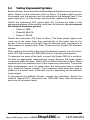
4.2 Equipment Troubleshooting..................................................... 11
4.3 Testing Various Cable Configurations......................................12
4.3.1 Metal Conduits.............................................................12
4.3.2 Grounded Neutral........................................................14
4.3.3 Neutral Grounded Through an Impedance..................15
4.3.4 Ungrounded System....................................................15
4.4 Commonly Asked Questions....................................................15
5. ARTIFICIAL NEUTRAL..................................................................... 17
Warning............................................................................................17
5.1 Description...............................................................................17
Shop for AEMC products online at:
www.ShopAEMC.ca
1.877.766.5412
5.2 Specifications...........................................................................19
5.2.1 Electrical......................................................................19
5.2.2 Mechanical...................................................................19
5.2.3 Safety...........................................................................19
5.3 Principle of Operation..............................................................20
5.4 Testing Ungrounded Systems..................................................21
6. MAINTENANCE.............................................................................. 22
6.1 Cleaning...................................................................................22
Repair and Calibration............................................................................23
Technical and Sales Assistance.............................................................23
Limited Warranty....................................................................................24
Warranty Repairs....................................................................................24
Shop for AEMC products online at:
www.ShopAEMC.ca
1.877.766.5412
CHAPTER 1
INTRODUCTION
Warning
These safety warnings are provided to ensure the safety of personnel and proper operation of the instrument.
•Never use this clamp on conductors with a voltage potential above
600Vrms.
•Never clamp around a conductor unless the clamp is terminated to
a measuring instrument with proper input impedance.
•Keep the jaw mating surfaces clean. If necessary, use a slightly
oiled cloth to remove oxidation.
•Ensure that the cables or bus bar are properly centered within the
clamp jaws.
•Stay away from other conductors which may create interference.
•Avoid leaving the clamp in damp places or exposing it to running
water.
•Due to shock or fire hazards, electrical connections of the instrument
should be performed only by qualified personnel and in accordance
with local, state, and federal electrical requirements.
1.1
International Electrical Symbols
This symbol signifies that the instrument is protected by double or
reinforced insulation. Use only specified replacement parts when
servicing the instrument.
This symbol on the instrument indicates a WARNING and that
the operator must refer to the user manual for instructions before
operating the instrument. In this manual, the symbol preceding
instructions indicates that if the instructions are not followed, bodily
injury, installation/sample and product damage may result.
Risk of electric shock. The voltage at the parts marked with this
symbol may be dangerous.
Ground Fault/Leakage Detector Model 2620
Shop for AEMC products online at:
www.ShopAEMC.ca
3
1.877.766.5412
1.2
Definition of Measurement Categories
Cat. I: For measurements on circuits not directly connected to the AC
supply wall outlet such as protected secondaries, signal level,
and limited energy circuits.
Cat. II: For measurements performed on circuits directly connected to
the electrical distribution system. Examples are measurements
on household appliances or portable tools.
Cat. III: For measurements performed in the building installation at
the distribution level such as on hardwired equipment in fixed
installation and circuit breakers.
Cat. IV: For measurements performed at the primary electrical supply
(<1000V) such as on primary overcurrent protection devices,
ripple control units, or meters.
1.3
Receiving Your Shipment
Upon receiving your shipment, make sure that the contents are consistent
with the packing list. Notify your distributor of any missing items. If the equipment appears to be damaged, file a claim immediately with the carrier and
notify your distributor at once, giving a detailed description of any damage.
Save the damaged packing container to substantiate your claim.
1.4
Ordering Information
Ground Fault/Leakage Detector Model 2620................... Cat. #2125.52
Includes user manual and warranty card.
1.4.1 Accessories and Replacement Parts
Artificial Neutral Model AN-1................................................ Cat. #1971.01
Includes instrument with soft carrying case; eight 1.5 V “AA” batteries; four 5 ft (1.5 m) colorcoded leads (green, red, black, blue); four color-coded alligator clips (green, red, black, blue);
and user manual.
Lead – Replacement............................................................ Cat. #2950.29
Set of {4} Color-coded 5 ft Safety Leads (4mm straight banana plugs on both ends), {4}
Color-coded safety alligator clips for use with the Artificial Neutral Model AN-1.
Adapter – 4mm Non-insulated for Safety Leads ................. Cat. #1017.45
(Converts male safety plugs to non-shielded male plugs)
Bag – Large Classic Tool Bag.............................................. Cat. #2133.71
Bag – Small Classic Tool Bag ............................................. Cat. #2133.72
4
Shop for AEMC products online at:
Ground Fault/Leakage Detector Model 2620
www.ShopAEMC.ca
1.877.766.5412
CHAPTER 2
PRODUCT FEATURES
2.1
Description
The Model 2620 measures leakage current shunted to ground caused by
insulation breakdown or leaks. It enables the operator to locate failures
when or before they occur, without shutting down equipment or spending
hours trouble-shooting.
It is designed specifically for locating low current faults on high current
loads. The detector is a sensitive AC current transformer capable of measuring differential or leakage current from 500µA, and may be used to
measure current up to 400A continuous duty.
The Model 2620 provides, on two ranges, 1mV/mAAC or 1mV/AAC. The
output leads are terminated with standard 4mm banana plugs capable of
interfacing with any standard multimeter.
Use of a digital multimeter with analog bar graph is recommended:
Digital to provide the proper voltage input impedance, and an analog bar
graph to track trends.
When the 2620 is used as a current leakage detector, it makes no difference
if the system is single-phase or poly-phase, or if the currents are in-phase
or out of phase, balanced or unbalanced.
The net magnetic field at any instant in time will be zero if all the conductors
surrounded by the current leakage detector are supplying all the current
delivered to and received from the load.
If any current is diverted through any alternate path to ground, such as
an insulation breakdown, the net loss will be detected producing a output
proportional to the amplitude of the fault current.
The Model 2620 may also be used simply as a highly accurate clamp-on
current probe. With its 4" jaw opening and range of 500µA to 400A, the 2620
provides a versatile way to analyze unbalanced current measurements,
leakage values on grounding conductors and ground loop currents.
Ground Fault/Leakage Detector Model 2620
Shop for AEMC products online at:
www.ShopAEMC.ca
5
1.877.766.5412
2.2
Connections
The Model 2620 is compatible with most DMMs, voltmeters, or other
voltage measuring instruments with the following features:
• Range and resolution capable of displaying 1mVAC of input.
• Voltmeter accuracy of 0.75% or better to take full advantage of the
accuracy of the probe.
• Minimum input impedance of 1MΩ.
Connect the probe to the multimeter or other instrument.
Select the appropriate AC voltage range on your multimeter.
The Model 2620 has two selectable output ranges. The 4A range will produce a mV/mA with an output of 4VAC at 4A. The 400A range produces
1mV/A with 400mVAC at 400A.
Warning: User Safety
Always use a DMM, voltmeter or other displaying device, appropriately
rated for the working voltage and for safety.
6
Shop for AEMC products online at:
Ground Fault/Leakage Detector Model 2620
www.ShopAEMC.ca
1.877.766.5412
CHAPTER 3
SPECIFICATIONS
3.1
Reference Conditions
Ambient temperature:
Relative humidity:
Position of the conductor:
Current frequency and form:
Superimposed DC current:
Continuous magnetic field:
Alternating magnetic field:
Proximity of external conductors:
Measuring device’s impedance:
3.2
23°C ± 3K
20 to 75% RH
Centered in the jaws
Sinusoidal 50/60Hz ± 0.2Hz, distortion <1%
No DC current
Earth field < 40 A/m
No external alternating magnetic field
None
≥ 10MΩ / 100pF
Electrical
4A Range
Nominal Current: 4AAC
Measurement Range: 0.5mA to 4AAC
Output Signal: 1mVAC/mAAC
4A Range
Accuracy
Phase Shift
0.5 to 10mA
3% of R ± 1mV
–
10 to 100mA
0.5% of R ± 0.5mV
< 15°
100mA to 4A
0.5% of R ± 0.5mV
< 10°
400A Range
Nominal Current: 400AAC
Measurement Range: 0.5A to 400AAC
Output Signal: 1mVAC/AAC
400A Range
Accuracy
Phase Shift
0.5 to 10A
10 to 100A
0.5% of R ± 0.5mV 0.35% of R ± 0.5mV
–
< 1°
Ground Fault/Leakage Detector Model 2620
Shop for AEMC products online at:
www.ShopAEMC.ca
100 to 400A
0.35% of R ± 1mV
< 0.6°
7
1.877.766.5412
Overloads
•
•
•
•
Ip limit current: permanent 400 AC RMS
Peak current: < 1000A
Permissible transient di/dt: ≤30A/μs
Conductor temperature: ≤ 70°C with a maximum peak of 90°C
Load Impedance (DMM): 1MΩ min
Frequency: 48 to 1000Hz
Errors caused by external influences:
Ambient temperature
Position of the gripped conductor
(max with not centred conductor)
Residual differential
(max with not centred conductor)
External fields, 1V/A (1)
External fields, 1mV/mA (1)
Coupled DC current, 1V/A
< 0.1% per 10K
0.1% typic of VOUT (non-differential
current); 0.2% max
0.1% typic of IP (differential current);
0.2% max
< 60mV of Vs
< 100μV of Vs
< 1mV for continuous 1A
(2)
Coupled DC current, 1mVm/A (2)
< 0.1mV for continuous 1A
Frequency, 1V/A
< 1.5% from 30Hz to 1KHz
(3)
Frequency, 1mV/mA (3)
< 0.5% from 30Hz to 1KHz
(1): 400 A/m 50Hz field perpendicular to the clamp opening
(2): DC current coupled onto an AC current
(3): Limited to 1KHz for 100A
3.3
Mechanical
Dimensions: 11.2 x 6.9 x 1.8" (285 x 175 x 45mm)
Weight: 2.9 lbs (1300g) approx
Jaw opening: 4.4" (112mm)
Maximum Jaw Gap: 9.8" (250mm)
Maximum Clamping Capacity: Max 4.5" (115mm) Ø cable
8
Shop for AEMC products online at:
Ground Fault/Leakage Detector Model 2620
www.ShopAEMC.ca
1.877.766.5412
3.4
Environmental
Operating Temperature:
-14° to 131°F (-10° to 55°C); 0 to 85% RH (non-condensing)
Storage Temperature:
-40° to 158°F (-40° to 70°C); 0 to 85% RH (non-condensing)
Operating Altitude: ≤2000m on uninsulated conductors
Transport Altitude: ≤12000m
3.5
Safety
Electrical Safety
EN 61010, 600V Cat. III
Pollution Degree: 2
Electromagnetc Compatibility
Industrial Environment: Criterion B
Emissivity (EN 61326-1)
Susceptibility (EN 61326-1)
Self-extinguishing Capability
Jaws and Casing: VO (UL 94)
Ground Fault/Leakage Detector Model 2620
Shop for AEMC products online at:
www.ShopAEMC.ca
9
1.877.766.5412
CHAPTER 4
OPERATION
4.1
Principle of Operation
4.1.1 Measuring Current Leakage
When a generator supplies an AC load through a pair of wires in an insulated
cable, the current going out on one wire is equal to the current returning;
their vector sum equals zero. A ground fault changes this equality, and
the leakage current detector picks it up, measures it, and provides an AC
voltage output proportional to the severity of fault causing the unbalance.
The ground conductor must not pass through the detector.
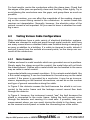
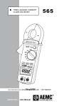
4.1.2 Interpreting the Measurement
Figure 1 is a schematic of a single-phase installation of a motor and an
oven, both grounded. The numbers indicate the amplitudes of the currents
in different conductors. This installation has no faults. If you clamp the
detector around the cables at points A,B,C or D, it will output zero.
A
115V/230V
B
15A
15A
10A
10A
C
D
5A
OVEN
ZERO
AMPERE
5A
5A
10A
MOTOR
GND
10A
10A
ZERO
AMPERE
GND
Figure 1
10
Shop for AEMC products online at:
Ground Fault/Leakage Detector Model 2620
www.ShopAEMC.ca
1.877.766.5412
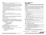
In Figure 2, there is a fault in the installation. At point A, the Model 2620
detects 1A (the difference between 16A and 15A), indicating a fault
downstream. At point C, it detects zero; therefore, the fault is not in the
oven. At points B and D, the detector picks up 1A, showing that the fault
is in the motor. If it gets worse, the leakage current will increase and the
circuit breaker will trip. This motor should be disconnected immediately
and repaired.
A
115V/230V
B
15A
15A
11A
10A
C
D
5A
OVEN
1A
5A
5A
10A
MOTOR
11A
1A
10A
1A
GND
RESIDUAL CURRENT: 1A
GND
Figure 2
In a three-phase installation the principle is the same. But here it is
necessary to pass all active conductors through the detector, including the
neutral if one is used. If this is done properly, the detector output will be
zero if there is no current leaking to ground. If it detects something other
than zero, there is a ground fault that should be repaired.
4.2
Equipment Troubleshooting
To locate a fault quickly, begin your troubleshooting at the incoming lowvoltage distribution header. Successively check each feeder. If the Model
2620 detects a ground fault, follow the feeder downstream, branch by
branch, to the equipment with the problem.
It is useful to take measurements periodically to create a history of the
quality of the insulation. This is good preventive maintenance which could
prove valuable later. If you detect a fault current that is very low initially
but increases from day to day, this means that electrical failure is imminent and should be taken care of during the next planned maintenance
shutdown.
Ground Fault/Leakage Detector Model 2620
Shop for AEMC products online at:
www.ShopAEMC.ca
11
1.877.766.5412
For best results, center the conductors within the clamp jaws. Check that
the edges of the jaws are perfectly clean and that they close tightly. Try to
avoid placing the conductors near the gaps, and group them as much as
possible.
If you are careless, you can affect the magnitude of the reading, depending on the current being carried in the conductors. In certain cases this
requires an interpretation. Normally, however, the absolute value of the
ground current is not important. All you need to know is whether the reading is zero.
4.3
Testing Various Cable Configurations
Older installations have a wide variety of electrical distribution systems.
Cables are clamped to walls and pass through metal conduits, and there
are many cases where a shielded cable was installed during revamping of
an area or addition to a building. If a cable is clamped to walls, detach it
and pull it away from the surface at several points, so the clamp can surround all the conductors.
4.3.1 Metal Conduits
Cables enclosed in metal conduits which are grounded are not a problem.
Simply apply the clamp around the conduit; the metal tube will not block
the measurement. Cables with a metal shield can be handled in the same
way as cable in metal conduit.
A grounded shield may present a problem. If it is a simple metal shield, like
a thin metal wrapping, it can be considered in the same way as the metal
conduit. If the armor is grounded by a conductor, it may be an inconvenience, depending on the terminal connections, as well as on the number
and type of ground connections along the cable.
In Figure 3 the detector senses the fault because the shield is not connected to the motor frame and the leakage current cannot flow back
through the detector.
In Figure 4, however, the instrument cannot “see” the fault because the
shield is connected to the motor frame, letting the fault current return
through the detector and causing it to read zero. If possible, take your
measurement where you can avoid closing the shield in the clamp, such
as the nearest control panel or inside the connecting box of the motor.
12
Shop for AEMC products online at:
Ground Fault/Leakage Detector Model 2620
www.ShopAEMC.ca
1.877.766.5412
Figure 3
Figure 4
One way to circumvent this shielded cable problem is shown in Figures
5 and 6. Here the shield is looped through the detector twice, so that the
reading will be that of the fault current.
Figure 5
Figure 6
Ground Fault/Leakage Detector Model 2620
Shop for AEMC products online at:
www.ShopAEMC.ca
13
1.877.766.5412
4.3.2 Grounded Neutral
It is easy to take measurements on this type of network, where major
faults trip the circuit breaker. Here, the detector can sense minor faults,
so repairs can be made before the problem gets worse. The inspection
method is the same as for a single-phase installation. Remember that on
a three-phase network, the currents add according to the vector sum law.
The Model 2620 measures the vector sum of the enclosed currents. If you
have, for example, a 400mA fault and a 250mA fault on the same phase,
the Model 2620 will detect 650mA. But if the two faults are on different
phases, they add vectorially and may even sum up to zero.
Figure 7 shows an example in which there are two separate faults: 400mA
on a machine in one shop, 250mA on a machine in another shop. The
vector sum is not 650mA, but 350mA. If you switch off the machine with the
250mA fault, the reading increases, indicating faults on different phases.
Shop 1
Fault on Phase 1
400mA
Shop 2
Fault on Phase 2
250mA
Figure 7
14
Shop for AEMC products online at:
Ground Fault/Leakage Detector Model 2620
www.ShopAEMC.ca
1.877.766.5412
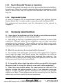
4.3.3 Neutral Grounded Through an Impedance
Follow the procedure the same way as for a grounded neutral installation,
but with care. When the neutral is grounded through an impedance, a fault (even a serious one) may not trip the circuit breaker, and the circuit will
stay live.
4.3.4 Ungrounded System
In order to measure on an ungrounded system, the optional Artificial
Neutral Model AN-1 must be used in conjunction with the Model 2620.
For measurement procedures, see the information in this manual in
Chapter 5.
4.4
Commonly Asked Questions
Q. I have found an indication of 40 to 50mA on one of the main feeders with 300A on the line. Is this value a fault?
A. With 300A on the line, it is possible to find an undesired current of that
magnitude. Different cables in the installation may not have equivalent
capacitance and resistance. These cables provide for high current and,
of course, we apply a high current. Therefore, we may have a capacitive
influence which corresponds to 45mA.
Q. Must the conductors be centered within the jaws?
A. You should avoid placing the conductors close against the magnetic
circuit near the gaps, and should group the conductors as much as
possible. Best results are obtained while centering the conductor. You
must also ensure that the jaw mating surface are perfectly clean and that
nothing prevents them from closing tightly.
Q. Is it possible when checking cables which run parallel, yet supply
the same load, to clamp the detector over each cable separately?
A. When there are parallel cables, the measurement is valid only if the
detector includes the cables together. In fact, if you take each one separately, it is highly probable that the distribution of current in the parallel
cables is not even. These differences can be caused by the fact that the
cables may not have exactly the same impedance.
Ground Fault/Leakage Detector Model 2620
Shop for AEMC products online at:
www.ShopAEMC.ca
15
1.877.766.5412
Q. I have detected faults of 400mA and 250mA on branch circuits
being supplied by the feeder. But clamping onto the incoming feeder
resulted in an indication of 350mA. Can you explain why 400mA +
250mA = 350mA?
A. The detector measures residual current; in other words, the vectorial
sum of the currents. If you have a 400mA fault and a 250mA fault on the
same phase, you have every chance of finding 650mA. But, if you have
two faults on different phases, they add as vectors actually, in a very theoretical case we could even find zero.
Q. The Model 2620 detects faults caused by insulation failures. How
does detecting faults with the detector differ from information resulting from megohmmeter insulation tests?
A. The Model 2620 will detect electrical faults while the equipment is still
in operation. This offers two distinct advantages. First, it is not necessary
to shut the equipment down, eliminating costly down time; and second,
you may detect faults that would not be evident under non-energized
conditions.
Q. Would it be possible to clamp the Model 2620 directly around the
grounding detector?
A. Yes, in some instances it may be possible to detect fault current on a
specific motor if there is a dedicated grounding path. However, if several
devices are sharing a common ground, it should be noted that the fault
may be occurring on any one (or multiple) of the devices.
16
Shop for AEMC products online at:
Ground Fault/Leakage Detector Model 2620
www.ShopAEMC.ca
1.877.766.5412
CHAPTER 5
ARTIFICIAL NEUTRAL
Warning
• The measurement of leakage current is done specifically with a clamp
designed for this purpose.
• The Artificial Neutral must be connected to a known low resistance
ground.
• If fault finding exceeds 15 minutes, remove the Artificial Neutral from
its carrying case.
• The Artificial Neutral must always be in the OFF position when con
necting the leads.
• Always make connections from the instrument to the circuit under
test.
• Always inspect the instrument and accessory leads for serviceability
prior to use. Replace defective parts immediately.
• Never use the instrument on electrical conductors rated above 600V.
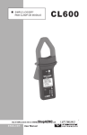
5.1
Description
The Artificial Neutral is an accessory for the AEMC Model 2620 Ground
Fault /Leakage Detector. It generates a grounded artificial neutral to allow
the measurement of fault currents on ungrounded 3 phase systems.
In an ungrounded system, the impedance between the transformer, neu
tral, and ground is infinity. Therefore, independent of the load current, no
ground fault current should flow. The Artificial Neutral creates an intermittent
return path for the ground fault current enabling the troubleshooter to
distinguish it from load current.
The Artificial Neutral is grounded intermittently through a relay driven by
an internal clock. This periodic grounding technique performs three functions:
• Limits the possibility of insulation faults within the case.
• Allows better discrimination of actual fault current.
• Limits instrument overheating
Ground Fault/Leakage Detector Model 2620
Shop for AEMC products online at:
www.ShopAEMC.ca
17
1.877.766.5412
Relay closure time is selected externally (Fast or Slow) so that the ground
fault clamp can be used on either an analog or digital display. When using
on digital multimeter, place the switch in the slow position; when using an
analog multimeter, set the switch to the fast position.
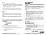
An internal buzzer, also driven by the relay, is activated each time the
neutral connection is grounded. Three lights, one for each phase, show
the presence of each of the three phases in the Artificial Neutral prior to
measurement. A fourth green light indicates the instrument is operating.
Safetyalligatorclips
Male-malesafetyleads,
4mmØ,length5ft(1.5m)doubleinsulation
ONlight
(green)
Carrying
Strap
A
V1
ON
B
V2
C
V3
600V max
ON
Slow
OFF
ON
Fast
WARNING
Connect and disconnect
only in the OFF position
SPECIFICATIONS
Working Voltage: 100 to 600V
Frequency: 45 to 65Hz
Batteries: 8 x 1.5V AA (LR6)
EN 61010, 600V, Cat. III, Pol. 2
ARTIFICIAL NEUTRAL
MODEL AN-1
3positionswitch:• ON,Slowtest
• OFF
• ON,Fasttest
Ventilationholes
Redlight,showing
voltagepresentand
phasefault
[Carrying case not shown]
Figure 8
18
Shop for AEMC products online at:
Ground Fault/Leakage Detector Model 2620
www.ShopAEMC.ca
1.877.766.5412
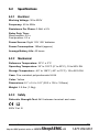
5.2
Specifications
5.2.1 Electrical
Working Voltage: 30 to 600V
Frequency: 45 to 65Hz
Resistance Per Phase: 3.9kΩ ± 5%
Relay Duty Time:
Slow position: 0.5 s
Fast position: 2.3 s
Power Source: Eight 1.5V “AA” batteries
Power Consumption: 180mA (approx)
Average Battery Life: 40 hours
5.2.2 Mechanical
Reference Temperature: 23°C ± 3°C
Operating Temperature: 32° to 122°F (0° to 50°C); 10 to 90% RH
Storage Temperature: -40° to 158°F (-40° to 70°C); 10 to 90% RH
Case: Fire resistant polycarbonate UL94
Color: Yellow
Dimensions: 8.7 x 5.4 x 5.9" (220 x 136 x 150mm)
Weight: 2.9 lbs (1.3kg)
5.2.3 Safety
Dielectric Strength Test: 6kV between terminal and case
600V Cat. III
Ground Fault/Leakage Detector Model 2620
Shop for AEMC products online at:
www.ShopAEMC.ca
19
1.877.766.5412
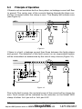
5.3
Principle of Operation
If there is not an insulation fault on the system, no leakage current will flow
to ground. The vector sum of the currents flowing through the three conductors enclosed within the clamp is zero. The display will indicate zero
(see Figure 9).
A
B
C
N
M
AN1
Figure 9
If there is a fault, a leakage current then flows between the faulty phase
and ground. The detection of this fault current on an ungrounded system
will be intermittent as determined by the rate of relay closure (Figure 10).
Figure 10
Due to the fault current, the vectorial sums of the current will no longer be
zero. Fault current will be indicated by the selection on the Model 2620
clamp of either 1mV per mA or 1mV per A AC.
20
Shop for AEMC products online at:
Ground Fault/Leakage Detector Model 2620
www.ShopAEMC.ca
1.877.766.5412
5.4
Testing Ungrounded Systems
Before starting, ensure that the Artificial Neutral batteries are in good condition. Switch on the instrument (Fast or Slow). The green light must be
illuminated, and the buzzer must be activated at the selected rate. If the
green light is out, or if the buzzer sounds weak, replace the batteries.
Switch the instrument OFF (green light off). Connect the leads to the
appropriate phases of the system under test. At this point, do not connect
the Artificial Neutral to ground.
• Phase A: RED
• Phase B: BLACK
• Phase C: BLUE
Switch the instrument ON (Fast or Slow). The three phase lights must
come on at the same time, then periodically, at the same rate as the
buzzer. If one or more do not light, stop the test and verify connections or
the existence of a phase fault. Note: There must be at least 30V between
phases.
After verifying that all the lights have illuminated properly, turn the instrument OFF and connect the GROUND lead to a known good ground.
To measure the value of the fault, connect the Model 2620 to a multime
ter with an appropriate measurement range. Enclose the three phase
conductors within the jaws. Switch ON the Artificial Neutral (Fast or Slow)
depending on the response time of the measuring instrument. The actual
fault measurement must be made when the instrument relay is closed
(e.g., when the buzzer sounds). The measured value when the relay is
closed is the actual value of the fault current, depending on the selected
output signal.
To disconnect the Artificial Neutral, reverse the procedure. Switch the
Artificial Neutral OFF, disconnect the GROUND lead, then disconnect
each one of the phase leads.
Ground Fault/Leakage Detector Model 2620
Shop for AEMC products online at:
www.ShopAEMC.ca
21
1.877.766.5412
CHAPTER 6
MAINTENANCE
WARNING:
• For maintenance use only specified factory replacement parts.
• To avoid electrical shock, do not attempt to perform any servicing
unless you are qualified to do so.
• To avoid electrical shock and/or damage to the instrument, do not
get water or other foreign agents into the case. Turn the instrument
OFF and disconnect the unit from all the circuits before opening
the case.
6.1
Cleaning
• Wipe the case and jaw covers with a lightly moistened cloth and
mild detergent.
• Do not use any abrasives or solvents.
• If rusted, the jaw mating surfaces of the Model 2620 may be lightly
sanded with very fine sandpaper and then very lightly oiled. Wipe
off excess oil and do not let it drip into the case.
22
Shop for AEMC products online at:
Ground Fault/Leakage Detector Model 2620
www.ShopAEMC.ca
1.877.766.5412
Repair and Calibration
To ensure that your instrument meets factory specifications, we recommend
that it be scheduled back to our factory Service Center at one-year intervals
for recalibration, or as required by other standards or internal procedures.
For instrument repair and calibration:
You must contact our Service Center for a Customer Service Authorization
Number (CSA#). This will ensure that when your instrument arrives, it will be
tracked and processed promptly. Please write the CSA# on the outside of the
shipping container. If the instrument is returned for calibration, we need to
know if you want a standard calibration, or a calibration traceable to N.I.S.T.
(Includes calibration certificate plus recorded calibration data).
Ship To:
Chauvin Arnoux®, Inc. d.b.a. AEMC® Instruments
15 Faraday Drive
Dover, NH 03820 USA
Phone:(800) 945-2362 (Ext. 360)
(603) 749-6434 (Ext. 360)
Fax: (603) 742-2346 or (603) 749-6309
E-mail:[email protected]
(Or contact your authorized distributor)
Costs for repair, standard calibration, and calibration traceable to N.I.S.T. are
available.
NOTE: You must obtain a CSA# before returning any instrument.
Technical and Sales Assistance
If you are experiencing any technical problems, or require any assistance with
the proper operation or application of your instrument, please call, mail, fax or
e-mail our technical support team:
Chauvin Arnoux®, Inc. d.b.a. AEMC® Instruments
200 Foxborough Boulevard
Foxborough, MA 02035 USA
Phone:(800) 343-1391
(508) 698-2115
Fax: (508) 698-2118
E-mail:[email protected]
www.aemc.com
NOTE: Do not ship Instruments to our Foxborough, MA address.
Ground Fault/Leakage Detector Model 2620
Shop for AEMC products online at:
www.ShopAEMC.ca
23
1.877.766.5412
Limited Warranty
The Model 2620 is warranted to the owner for a period of one year from
the date of original purchase against defects in manufacture. This limited warranty is given by AEMC® Instruments, not by the distributor from
whom it was purchased. This warranty is void if the unit has been tampered with, abused or if the defect is related to service not performed by
AEMC® Instruments.
For full and detailed warranty coverage, please read the Warranty
Coverage Information, which is attached to the Warranty Registration
Card (if enclosed) or is available at www.aemc.com. Please keep the
Warranty Coverage Information with your records.
What AEMC® Instruments will do:
If a malfunction occurs within the one-year period, you may return the instrument
to us for repair, provided we have your warranty registration information on file
or a proof of purchase. AEMC® Instruments will, at its option, repair or replace
the faulty material.
REGISTER ONLINE AT:
www.aemc.com
Warranty Repairs
What you must do to return an Instrument for Warranty Repair:
First, request a Customer Service Authorization Number (CSA#) by phone
or by fax from our Service Department (see address below), then return the
instrument along with the signed CSA Form. Please write the CSA# on the
outside of the shipping container. Return the instrument, postage or shipment
pre-paid to:
Ship To:
Chauvin Arnoux®, Inc. d.b.a. AEMC® Instruments
15 Faraday Drive • Dover, NH 03820 USA
Phone:(800) 945-2362 (Ext. 360)
(603) 749-6434 (Ext. 360)
Fax: (603) 742-2346 or (603) 749-6309
E-mail:[email protected]
Caution: To protect yourself against in-transit loss, we recommend you insure
your returned material.
NOTE: You must obtain a CSA# before returning any instrument.
24
Shop for AEMC products online at:
Ground Fault/Leakage Detector Model 2620
www.ShopAEMC.ca
1.877.766.5412
Shop for AEMC products online at:
www.ShopAEMC.ca
1.877.766.5412
05/09
99-MAN 100292 v4
Chauvin Arnoux®, Inc. d.b.a. AEMC® Instruments
15 Faraday Drive • Dover, NH 03820 USA • Phone: (603) 749-6434 • Fax: (603) 742-2346
www.aemc.com
Shop for AEMC products online at:
www.ShopAEMC.ca
1.877.766.5412