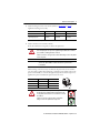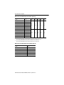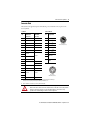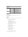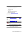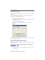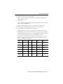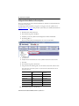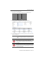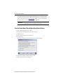
1
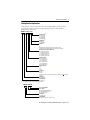
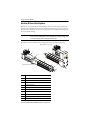
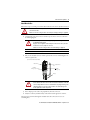
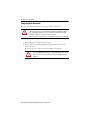
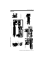
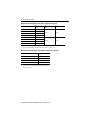
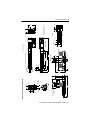
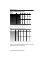
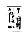
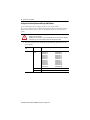
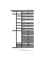
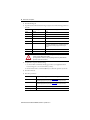
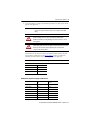
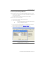
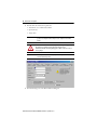
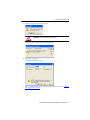
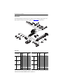
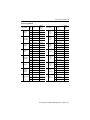
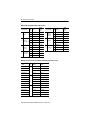
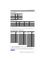
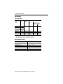
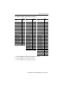
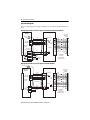
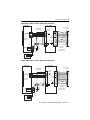
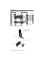
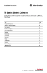
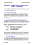
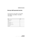
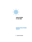
Installation Instructions MP-Series Electric Cylinders Catalog Numbers MPAR-x1xxxB, MPAR-x1xxxE, MPAR-x2xxxC, MPAR-x2xxxF, MPAR-x3xxxE, MPAR-x3xxxH Topic Page Important User Information 2 Catalog Number Explanation 3 About the MP-Series Electric Cylinders 4 Before You Begin 5 Install the Electric Cylinder 8 Mount the Electric Cylinder 10 Change Connector Orientation 12 Dimensions 13 Connector Data 19 Commissioning 20 Maintenance 35 Troubleshooting 36 Accessories 38 Specifications 42 Additional Resources 47 2 MP-Series Electric Cylinders Important User Information Solid-state equipment has operational characteristics differing from those of electromechanical equipment. Safety Guidelines for the Application, Installation and Maintenance of Solid State Controls (Publication SGI-1.1 available from your local Rockwell Automation® sales office or online at http://www.rockwellautomation.com/literature/) describes some important differences between solid-state equipment and hard-wired electromechanical devices. Because of this difference, and also because of the wide variety of uses for solid-state equipment, all persons responsible for applying this equipment must satisfy themselves that each intended application of this equipment is acceptable. In no event will Rockwell Automation, Inc. be responsible or liable for indirect or consequential damages resulting from the use or application of this equipment. The examples and diagrams in this manual are included solely for illustrative purposes. Because of the many variables and requirements associated with any particular installation, Rockwell Automation, Inc. cannot assume responsibility or liability for actual use based on the examples and diagrams. No patent liability is assumed by Rockwell Automation, Inc. with respect to use of information, circuits, equipment, or software described in this manual. Reproduction of the contents of this manual, in whole or in part, without written permission of Rockwell Automation, Inc., is prohibited. Throughout this manual, when necessary, we use notes to make you aware of safety considerations. WARNING: Identifies information about practices or circumstances that can cause an explosion in a hazardous environment, which may lead to personal injury or death, property damage, or economic loss. ATTENTION: Identifies information about practices or circumstances that can lead to personal injury or death, property damage, or economic loss. Attentions help you identify a hazard, avoid a hazard and recognize the consequences. SHOCK HAZARD: Labels may be on or inside the equipment, for example, drive or motor, to alert people that dangerous voltage may be present. BURN HAZARD: Labels may be on or inside the equipment, for example, drive or motor, to alert people that surfaces may reach dangerous temperatures. IMPORTANT Identifies information that is critical for successful application and understanding of the product. Rockwell Automation Publication MPAR-IN001D-EN-P - September 2012 MP-Series Electric Cylinders 3 Catalog Number Explanation Catalog numbers consist of various characters, each of which identifies a specific version or option for that component. Use the catalog numbering chart below to understand the configuration of your actuator. MP AR - xx xxx x - x x x (1) Motor Mounting (1) A = Axial (in-line) B = Top (parallel) D = Left (parallel) E = Right (parallel) Holding Brake (1) 2 = No Brake 4 = 24V DC Brake Feedback (1) A= B= M = Multi-turn, absolute high-resolution encoder, frame size 63 only V = Multi-turn, absolute high-resolution encoder, frame size 32 and 40 only Mechanical Drive/Screw Lead, Motor Type B = 3.0 mm/rev (0.118 in./rev) C = 5.0 mm/rev (0.197 in./rev) E = 10.0 mm/rev (0.394 in./rev) F = 12.7 mm/rev (0.50 in./rev) H = 20.0 mm/rev (0.787 in./rev) Rod Stroke Length 100 = 100 mm (3.94 in.) 200 = 200 mm (7.87 in.) 300 = 300 mm (11.81 in.) 400 = 400 mm (15.75 in.) 600 = 600 mm (23.62 in.) 800 = 800 mm (27.56 in.) Actuator Frame Size 1 = 32 2 = 40 3 = 63 Voltage Class A = 200V B = 400V X = Actuator cylinder replacement part (refer to Actuator Cylinders on page 41 for ordering examples) Actuator Type AR = Actuator Rod Bulletin Number MP = MP-Series® This field does not apply to actuator cylinder replacement parts. MP AR - xx xxxxxx Accessory Item Number Accessory Type NA = Axial (in-line) Mounting Accessory NP = Parallel Mounting Accessory NE = Rod-end Accessory Actuator Type AR = Actuator Rod Bulletin Number MP = MP-Series or TL-Series ® Actuator Accessory Rockwell Automation Publication MPAR-IN001D-EN-P - September 2012 4 MP-Series Electric Cylinders About the MP-Series Electric Cylinders MP-Series electric cylinders feature multi-turn high resolution encoders and are available with 24V DC brakes. The MP-Series motor rotates a ballscrew drive that converts rotary motion into linear movement. This linear movement results in the piston rod extending and retracting from the electric cylinder housing. The MP-A/Bxxxxx-x2x electric cylinders are non-braking. When there is no input torque, the piston rod can be moved freely. You can achieve self-locking of your motion system by using motors with an integrated brake or with high self-braking torque. IMPORTANT The MP-Series electric cylinders have been designed for exact positioning at high speeds. MPAR-A1100E-V2B MP-Series Electric Cylinder 1 2 3 4 (x4) Hot surface. Do not touch. CAUTION 5 6 MPAR-A1100E-V2A MP-Series Electric Cylinder 7 (x4) 8 9 Item Description 1 Power connector 2 Feedback connector 3 MP-Series motor 4 Motor mounting bolts 5 Actuator cylinder 6 Breather port 7 Hollow bolts with internal treads for fastening 8 Piston rod 9 Wrench flats for counteracting torque on piston rod 10 Accessories mounting holes Rockwell Automation Publication MPAR-IN001D-EN-P - September 2012 10 (x4) MP-Series Electric Cylinders 5 Before You Begin Remove all packing material, wedges, and braces from within and around the item. After unpacking, verify the nameplate catalog number against the purchase order. 1. Remove packaging polyethylene foil and cardboard. The packing materials are recyclable, except for oiled paper, which is waste. 2. Remove the electric cylinder carefully from its shipping container. Consider the weight of the electric cylinder. Depending on the design, the electric cylinder can weigh up to 20.6 kg (45.4 lb). 3. Visually inspect the electric cylinder for damage. 4. Examine the electric cylinder frame, piston shaft, and hollow bolts for defects. 5. Notify the carrier of shipping damage immediately. ATTENTION: Do not attempt to open and modify the electric cylinder beyond changing motor connector orientation as described on page 12. Only a qualified Allen-Bradley® employee can service the internal working of the electric cylinder or motor. Failure to observe these safety precautions could result in personal injury or damage to equipment. Planning Your Installation Refer to the Kinetix® Motion Control Selection Guide, publication GMC-SG001, for the specifications and additional products referenced in this section: • This product can be operated in compliance with the relevant safety regulations only if the maximum loading limits are observed. ATTENTION: The electric-cylinder is not intended to be used in applications where side-loading occurs. Loads must be guided and supported. Aligned load with the line-of-motion of the piston rod. Side loading will reduce the lifetime of the electric-cylinder. • If you are mounting your electric cylinder in a vertical or sloping position, include safety measures that will control the workload should the spindle nut fail. ATTENTION: Uncontrolled moving masses can cause injury or damage to property. If there is a spindle nut fracture inside the actuator cylinder due to wear, the working mass will drop down. Check whether additional external safety measures are required to prevent damage in the event of a spindle nut fracture. • Corrosive environments reduce the service life of electric cylinders. • Depending on the workload, the piston rod will bend. Refer to the piston-rod deflection specifications for limitations. Rockwell Automation Publication MPAR-IN001D-EN-P - September 2012 6 MP-Series Electric Cylinders • Motor feedback, auxiliary feedback, and I/O connector kits are not included, but can be purchased separately. • Factory manufactured feedback and power cables are available in standard cable lengths. They provide environmental sealing and shield termination. Contact your Allen-Bradley sales office or refer to the selection guide for cables. Electric Cylinders with Brake Option The brake option on this servo motor is a spring-set holding brake that releases when voltage is applied to the brake coil. A separate power source is required to disengage the brake. This power source can be applied by a servo motor controller or manual operator control. If system main power fails, holding brakes can withstand occasional use as stopping brakes. However, this creates rotational mechanical backlash that is potentially damaging to the system, increases brake wear, and reduces brake life. An unpowered electric cylinder will require a brake to maintain its position if the force on the actuator exceeds the Back Drive Force listed in Kinetix Linear Motion Specifications Technical Data, publication GMC-TD002. A brake can be use with the actuator to keep it from backdriving, typically in vertical applications. A brake may be used for safety reasons or for energy savings allowing the actuator to hold position when unpowered. IMPORTANT Holding brakes are not designed to stop rotation of the motor shaft, nor are they intended to be used as a safety device. They are designed to hold a motor shaft at 0 rpm for up to the rated brake holding torque. The recommended method of preventing motor shaft rotation is a four step process: first, command the servo drive to 0 rpm; second, verify the motor is at 0 rpm; third, engage the brake; and fourth, disable the drive. Disabling the drive removes the potential for brake wear caused by a badly-tuned servo system oscillating the shaft. Rockwell Automation Publication MPAR-IN001D-EN-P - September 2012 MP-Series Electric Cylinders 7 Preventing Electrical Noise Electromagnetic interference (EMI), commonly called electrical noise, can reduce motor performance. Effective techniques to counter EMI include filtering the AC power, using shielded cables, separating signal cables from power wiring, and practicing good grounding techniques. Follow these guidelines to avoid the effects of EMI: • Isolate the power transformers or install line filters on all AC input power lines. • Physically separate signal cables from motor cabling and power wiring. Do not route signal cables with motor and power wires, or over the vent openings of servo drives. • Ground all equipment by using a single-point parallel ground system that employs ground bus bars or large straps. If necessary, use additional electrical-noise reduction techniques to reduce EMI in noisy environments. Refer to System Design for Control of Electrical Noise Reference Manual, publication GMC-RM001, for additional information on reducing the effects of EMI. Build and Route Cables Knowledgeable cable routing and careful cable construction improves system electromagnetic compatibility (EMC). Follow these steps to build and install cables. 1. Keep wire lengths as short as physically possible. 2. Route signal cables (encoder, serial, analog) away from motor and power wiring. 3. Separate cables by 0.3 m (1 ft) minimum for every 9 m (30 ft) of parallel run. 4. Ground both ends of the encoder cable shield and twist the signal wire pairs to prevent electromagnetic interference (EMI) from other equipment. ATTENTION: High voltage can be present on the shield of a power cable if the shield is not grounded. Make sure there is a connection to ground for any power cable shield. Failure to observe these safety precautions could result in personal injury or damage to equipment. Rockwell Automation Publication MPAR-IN001D-EN-P - September 2012 8 MP-Series Electric Cylinders Install the Electric Cylinder The installation must comply with all local regulations and use of equipment and installation practices that promote electromagnetic compatibility and safety. ATTENTION: Unmounted electric cylinders, disconnected mechanical couplings, and disconnected cables are dangerous if power is applied. Disassembled equipment should be appropriately identified (tagged-out) and access to electrical power restricted (locked-out). Failure to observe these safety precautions could result in personal injury. ATTENTION: Make sure that cables are installed and restrained to prevent uneven tension or flexion at the cable connectors. Excessive and uneven lateral force at the cable connectors may result in the connector’s environmental seal opening and closing as the cable flexes. Failure to observe these safety precautions could result in damage to the electric cylinder motor and its components. ATTENTION: Damage may occur to the electric cylinder bearings and the feedback device if a sharp impact to the piston rod is applied during installation. Do not strike the piston rod with tools during installation or removal. Do not attempt to rotate the piston rod during installation. Rotating the piston rod will break the mechanism that allows the electric cylinder to extend and retract. Failure to observe these safety precautions could result in damage to the electric cylinder and its components. Follow these steps to install the electric cylinder. 1. Provide sufficient clearances in the area of the electric cylinder for it to stay within its specified operating temperature range. Refer to Specifications on page 42 for the operating temperature range. Do not enclose the electric cylinder unless forced air is blown across the electric cylinder for cooling. Keep other heat producing devices away from the electric cylinder. IMPORTANT Position the electric cylinder so that all of the operating parts are accessible and the breather port is not covered. 2. Make sure the mounting surface supports the electric cylinder evenly so that it is free of mechanical stress and distortion. The evenness of support surface should be 0.2 mm (0.008 in.). ATTENTION: Do not modify the settings of the screws and the threaded pins. The electric cylinder must not be fastened by the front cover alone when used with high loads. Heavy tensile strain may cause the screws in the cover to pull out. Rockwell Automation Publication MPAR-IN001D-EN-P - September 2012 MP-Series Electric Cylinders 9 3. Attach mounting accessories to the electric cylinder; see Accessories on page 38. Tighten the fastening screws evenly. Attribute Frame 32 Frame 40 Frame 63 Internal thread of cover screws M6 M6 M8 Tightening torque, max (1) 5 N•m (3.69 lb•ft) 5 N•m (3.69 lb•ft) 9 N•m (5.90 lb•ft) (1) Unless otherwise noted, the torque value has a ±20% tolerance. 4. Attach rod-end accessories and the workload. Be sure the workload center of gravity is centric to the piston rod. ATTENTION: Damage may occur to the electric cylinder bearings and the feedback device if sharp impact to the piston rod is applied during installation. Do not strike the piston rod with tools during installation or removal. Failure to observe these safety precautions could result in damage to the electric cylinder and its components. IMPORTANT Do not twist or rotate the piston rod. If the piston rod is rotated, the absolute position of the electric cylinder will be lost and the absolute home position must be re-established. When fastening a rod-end accessory or workload to the piston rod, use two wrenches. Use one wrench to tighten the mounting nut or rod-end accessory and the other, on the piston-rod wrench flats, to counteract the applied torque. Be sure that the torque is not applied to the piston rod and that the piston rod does not rotate. Frame Size Piston Rod Thread Wrench Flats Width 32 M10 x 1.25 10 mm 40 M12 x 1.25 13 mm 63 M16 x 1.5 17 mm Wrench Flat ATTENTION: Do not rotate the piston rod during installation. Rotating the piston rod will break the mechanism that lets the electric cylinder extend and retract. Use two wrenches to install the workload. Failure to observe these safety precautions could result in damage to the electric cylinder and its components Rockwell Automation Publication MPAR-IN001D-EN-P - September 2012 10 MP-Series Electric Cylinders If you are using a coupling piece attachment, catalog number MPAR-NE3612x, or trunnion mounting kit, catalog number MPAR-NA1635xx, see Accessories on page 38 for torque values. If you are using a rod guide accessory, catalog number MPAR-NE34xxx or MPAR-NE150xxx, adjust the guides of the workload and the electric cylinder so that they are exactly parallel. This avoids excessive wear on the guide. Mount the Electric Cylinder 1. Use stainless steel fasteners to mount your electric cylinder to your application. 2. Attach power and feedback cables after the electric cylinder is mounted, and use a drip loop in the cable to keep liquids away from the connectors. BURN HAZARD: Outer surfaces of the motor can reach high temperatures, 65 °C (149 °F), during electric cylinder operation. Take precautions to prevent accidental contact with hot surfaces. Failure to observe these safety precautions can result in personal injury. ATTENTION: Consider electric-cylinder surface temperature when selecting motor-mating connections and cables. Failure to observe these safety precautions can result in personal injury or damage to equipment. ATTENTION: Keyed connectors must be properly aligned and hand-tightened the recommended number of turns. Improper connector alignment is indicated by the need for excessive force, such as the need for the use of tools, to fully seat connectors. Failure to observe these safety precautions could result in damage to the motor and cable, and their components. Rockwell Automation Publication MPAR-IN001D-EN-P - September 2012 MP-Series Electric Cylinders 11 Attach Motor Cables Follow these steps to attach the power and feedback cables after the electric-cylinder is mounted. ATTENTION: Consider electric-cylinder surface temperature when selecting motor-mating connections and cables. Failure to observe these safety precautions can result in personal injury or damage to equipment. 1. Carefully align each cable connector with the respective motor connector as shown in the following diagram. ATTENTION: Keyed connectors must be properly aligned and hand-tightened the recommended number of turns. Improper connector alignment is indicated by the need for excessive force, such as the need for the use of tools, to fully seat connectors. Failure to observe these safety precautions can result in damage to equipment. IMPORTANT Remove the O-ring from the motor connector. 2. Fully seat the feedback connector and the power/brake connector and hand tighten the collar one-quarter turn. Top of connector is relative to motor orientation. Power Connector Flat Surface with Logo on Top Feedback Connector Flat Surface with Logo on Top Drip Loop ATTENTION: Make sure that cables are installed and restrained to prevent uneven tension or flexion at the cable connectors. Excessive and uneven lateral force at the cable connectors may result in the connector’s environmental seal opening and closing as the cable flexes. Failure to observe these safety precautions can result in damage to the electric-cylinder motor and its components. 3. Form a drip loop in the cable to keep liquids away from the connectors. 4. Verify the continuity and functionality of the thermal switch signals, TS+ and TS-. These signals are transmitted through the feedback cable that connects the motor to its controlling drive. Rockwell Automation Publication MPAR-IN001D-EN-P - September 2012 12 MP-Series Electric Cylinders Change Connector Orientation You can rotate the circular DIN-connector housings up to 180° in either direction. ATTENTION: You can rotate the connectors into a fixed position during installation of the electric cylinder and keep them in that position without further adjustment. Strictly limit the applied forces and the number of times the connector is rotated to be sure that connectors meet the requirements of IP66 for the motor portion of the electric cylinder. Failure to observe these safety precautions can result in damage to the motor and its components Follow these steps to rotate the DIN connectors. 1. Mount and fully seat a mating cable on the connector. 2. Grasp the connector and cable plug by their housings and slowly rotate them to the outside of the motor. If necessary, repeat this step for each connector (feedback or power/brake). ATTENTION: Apply force only to the connectors; do not apply force to the cable. Do not use tools, for example, pliers and vise-grips, to assist with the rotation of the connector. Failure to observe these safety precautions can result in personal injury or damage to equipment. Rockwell Automation Publication MPAR-IN001D-EN-P - September 2012 Bulletin MPAR-x1xxxx-xxB/D/E (parallel configuration) Flat for wrench. Feedback Connector 6.0 (0.24) (x4) 45.5 (1.79) 32.5 (1.28) L71 45.5 (1.79) LB Power/Brake Connector M6 (x4) 32.5 (1.28) 56.0 (2.20) 18 (0.71) 27.5 (1.08) 122+ (4.80) + 32.5 (1.28) 60 (2.36) L7 32.5 (1.28) LB Ø30.0 (1.18) d11 M10x1.25 12.0 (0.47) Ø16.0 (0.63) h9 + = Plus Stroke Length LE Dimensions are in mm (in.). MPAR-x1xxxx-xxD 26 (1.02) 66.5 (2.62) MPAR-x1xxxx-xxB 148 ±1.0 + (5.83 ± 0.04)+ 24 (0.94) 10.0 (0.39) 26 (1.02) Bulletin MPAR-x1xxxx-xxA (in-line configuration) MPAR-x1xxxx-xxE See Detail A 92.5 ± 1 (3.64 ± 0.04) 157 (6.18) 22 (0.87) MP-Series Electric Cylinders (frame 32) 94 66.5 (3.70) (2.62) 10 Detail A 16.0 (0.63) Dimensions ZJ, L7, and L71 are with piston rod fully retracted. 55.0 (2.16) MP-Series Electric Cylinders 13 Dimensions Rockwell Automation Publication MPAR-IN001D-EN-P - September 2012 14 MP-Series Electric Cylinders MP-Series Electric Cylinder Dimensions (in-line configuration, frame 32) Electric Cylinder Cat. No. L7(1) mm (in.) MPAR-x1100B-V2A 445.7 (17.55) MPAR-x1200B-V2A 545.7 (21.48) MPAR-x1300B-V2A 645.7 (25.42) MPAR-x1400B-V2A 745.7 (29.36) MPAR-x1100E-V2A 470.7 (18.53) MPAR-x1200E-V2A 570.7 (22.47) MPAR-x1300E-V2A 670.7 (26.41) MPAR-x1400E-V2A 770.7 (30.34) LB (1) mm (in.) LE (2) mm (in.) 126.5 (4.98) 52.4 (2.06) 151.5 (5.96) 77.2 (3.04) (1) If you are ordering an MPAR-x1xxxx-V4x actuator with brake, add 36.1 mm (1.42 in.) to dimensions L7 and LB. (2) If you are ordering an MPAR-x1xxxx-V4x actuator with brake, add 33.4 mm (1.31 in.) to dimension LE. MP-Series Electric Cylinder Dimensions (parallel configuration, frame 32)(1) Electric Cylinder Cat. No. L71 mm (in.) MPAR-x1100B-V2B/D/E 326.0 (12.8) MPAR-x1200B-V2B/D/E 426.0 (16.8) MPAR-x1300B-V2B/D/E 526.0 (20.7) MPAR-x1400B-V2B/D/E 626.0 (24.6) (1) For complete dimensions of the parallel configuration electric cylinders, use the in-line dimensions for an electric cylinder with the same rod-stroke length and the dimensions from this table. Rockwell Automation Publication MPAR-IN001D-EN-P - September 2012 Bulletin MPAR-x2xxxx-xxB/D/E (parallel configuration) L71 54 (2.12) Flat for wrench. Feedback Connector 6.0 (0.24) (x4) 54 (2.12) 38 (1.50) LB Power/Brake Connector M6 (x4) 38 (1.50) MP-Series Electric Cylinders (frame 40) LC 24 (0.94) HC 21.5 (0.85) C GC 146.5+ (5.77) + L7 38 (1.50) PW 38 (1.50) AD MPAR-x2xxxx-xxD 30 (1.18) MPAR-x2xxxx-xxB 176.5 ± 1.0 + (6.95 ± 0.04) + 28.5 (1.12) 10.5 (0.413) 30 (1.18) MPAR-x2xxxx-xxE See Detail A Bulletin MPAR-x2xxxx-xxA (in-line configuration) LB Ø35.0 (1.38) d11 M12x1.25 16.0 (0.63) Ø20.0 (0.79) h9 + = Plus Stroke Length LE Dimensions are in mm (in.). AD 13 Detail A HD 16.0 (0.63) Dimensions ZJ, L7, and L71 are with piston rod fully retracted. P MP-Series Electric Cylinders 15 Rockwell Automation Publication MPAR-IN001D-EN-P - September 2012 16 MP-Series Electric Cylinders MP-Series Electric Cylinder Dimensions (in-line, frame 40) Electric Cylinder Cat. No. L7 (1) mm (in.) MPAR-x2100C-V2A 501.2 (19.73) MPAR-x2200C-V2A 601.2 (23.67) MPAR-x2300C-V2A 701.2 (27.61) MPAR-x2400C-V2A 801.2 (31.54) MPAR-x2600C-V2A 1001.2 (39.42) MPAR-x2100F-V2A 492.1 (19.37) MPAR-x2200F-V2A 592.1 (23.31) MPAR-x2300F-V2A 692.1 (27.25) MPAR-x2400F-V2A 792.1 (31.19) MPAR-x2600F-V2A 992.1 (39.06) LB (1) mm (in.) LE (2) mm (in.) 151.5 (5.96) 77.2 (3.04) 55.0 (2.17) 66.5 (2.62) 94.0 (3.70) 140.1 (5.52) 65.1 (2.56) 70.0 (2.76) 74.0 (2.91) 109.0 (4.29) P mm (in.) AD mm (in.) (1) If you are ordering an MPAR-x2xxxC-V4x actuator with brake, add 36.1 mm (1.42 in.) to dimensions L7 and LB. (2) If you are ordering an MPAR-x2xxxC-V4x actuator with brake, add 33.4 mm (1.31 in.) to dimension LE. HD mm (in.) If you are ordering an MPAR-x2xxxF-V4x actuator with brake, add 39.0 mm (1.54 in.) to dimensions L7 and LB. If you are ordering an MPAR-x2xxxF-V4x actuator with brake, add 24.7 mm (0.97 in.) to dimension LE. MP-Series Electric Cylinder Dimensions (parallel, frame 40)(1) Electric Cylinder Cat. No. L71 mm (in.) MPAR-x2100C-V2B/D/E 356.5 (14.03) MPAR-x2200C-V2B/D/E 456.5 (17.97) MPAR-x2300C-V2B/D/E 556.5 (21.91)) MPAR-x2400C-V2B/D/E 656.5 (25.84) MPAR-x2600C-V2B/D/E 856.5 (33.72) MPAR-x2100F-V2B/D/E 369.5 (14.55) MPAR-x2200F-V2B/D/E 469.5 (18.48) MPAR-x2300F-V2B/D/E 569.5 (22.42) MPAR-x2400F-V2B/D/E 669.5 (26.36) MPAR-x2600F-V2B/D/E 869.5 (34.23) LC mm (in.) HC mm (in.) C (2) mm (in.) CG mm (in.) PW mm (in.) 56.0 (2.20) 157.0 (6.18) 91.5 (3.60) 27.0 (1.06) 60.0 (2.36) 69.0 (2.72) 188.5 (7.42) 102.5 (4.035) 38.0 (1.50) 86.0 (3.38) (1) For complete dimensions of the parallel configuration electric cylinders, use the in-line dimensions for an electric cylinder with the same rod-stroke length and the dimensions from this table. (2) The tolerance for this dimension is ±1.0 mm (0.04 in.). Actuators are designed to metric dimensions. Inch dimensions are approximate conversions from millimeters. Dimensions without tolerances are for reference. Rockwell Automation Publication MPAR-IN001D-EN-P - September 2012 Bulletin MPAR-x3xxxx-xxB/D/E (parallel configuration) L71 75.5 (2.97) Flat for wrench. Feedback Connector 6.0 (0.24) (x4) 75.5 (2.97) 56.5 (2.22) LB Power/Brake Connector M6 (x4) 56.5 (2.22) 82 (3.23) MP-Series Electric Cylinders (frame 63) 45 (1.77) 177+ (6.97) + 56.5 (22.2) 110 (4.33) AD L7 MPAR-x3xxxx-xxD 36 (1.42) 56.5 (22.2) MPAR-x3xxxx-xxB 214 ± 1.0 + (8.42 ± 0.04) + 34 (1.34) 15 (0.59) 37 (1.46) MPAR-x3xxxx-xxE 120 ±1.0 (4.72 ± 0.04) 255 (10.04) 32 (1.26) 28.5 (1.12) See Detail A Bulletin MPAR-x3xxxx-xxA (in-line configuration) LE LB Ø45.0 (1.77) d11 20.0 (0.79) Ø28.0 (1.10 h9 + = Plus Stroke Length Dimensions are in mm (in.). M16x1.5 AD 17 Detail A Dimensions ZJ, L7, and L71 are with piston rod fully retracted. P 17.0 (0.67) HD MP-Series Electric Cylinders 17 Rockwell Automation Publication MPAR-IN001D-EN-P - September 2012 18 MP-Series Electric Cylinders MP-Series Electric Cylinder Dimensions (in-line, frame 63) Electric Cylinder Cat. No. L7 (1) mm (in.) MPAR-x3100E-M2A 603.8 (23.77) MPAR-x3200E-M2A 703.8 (27.71) MPAR-x3300E-M2A 803.8 (31.65) MPAR-x3400E-M2A 903.8 (35.58) MPAR-x3600E-M2A 1103.8 (43.46) MPAR-x3800E-M2A 1303.8 (51.33) MPAR-x3100H-M2A 574.8 (22.63) MPAR-x3200H-M2A 674.8 (26.57) MPAR-x3300H-M2A 774.8 (30.50) MPAR-x3400H-M2A 874.8 (34.44) MPAR-x3600H-M2A 1074.8 (42.31) MPAR-x3800H-M2A 1274.8 (50.19) LB (1) mm (in.) LE (2) mm (in.) P mm (in.) AD mm (in.) HD mm (in.) 178.8 (7.04) 121.5 (4.78) 89.4 (3.52) 80.9 (3.19) 125.7 (4.95) 149.8 (5.90) 92.5 (3.64) 98.3 (3.87) 83.9 (3.30) 132.8 (5.23) (1) If you are ordering an MPAR-x3xxxE-M4x actuator with brake, add 34.5 mm (1.36 in.) to dimensions L7 and LB. (2) If you are ordering an MPAR-x3xxxE-M4x actuator with brake, add 34.5 mm (1.36 in.) to dimension LE. If you are ordering an MPAR-x3xxxH-M4x actuator with brake, add 48.5 mm (1.91 in.) to dimensions L7 and LB. If you are ordering an MPAR-x3xxxH-M4x actuator with brake, add 48.5 mm (1.91 in.) to dimension LE. MP-Series Electric Cylinder Dimensions (parallel, frame 63) Electric Cylinder Cat. No. L71 mm (in.) MPAR-x3100x-M2B/D/E 428.0 (16.85) MPAR-x3200x-M2B/D/E 528.0 (20.79) MPAR-x3300x-M2B/D/E 628.0 (24.72) MPAR-x3400x-M2B/D/E 728.0 (28.66) MPAR-x3600x-M2B/D/E 928.0 (36.53) MPAR-x3800x-M2B/D/E 1128.0 (44.41) Rockwell Automation Publication MPAR-IN001D-EN-P - September 2012 MP-Series Electric Cylinders 19 Connector Data This table lists the signal descriptions for feedback, power, and brake connector pins on the electric cylinder. Feedback Power and Brake Pin Signal Name MPAR-Axxxxx (200V class) Signal Name MPAR-Bxxxxx (400V class) Pin Signal Name 1 Sin+ Sin+ A Phase U (1) (1) 2 Sin- Sin- B Phase V 3 Cos+ Cos+ C Phase W (1) 4 Cos- Cos- D Ground (1) 5 Data+ Data+ E Reserved (1) 6 Data- Data- F MBRK+ (1) (2) G MBRK- (1) (2) 7 B A L C G F H D E Intercontec P/N BEDC0091NN00000217000 Reserved 8 H Reserved Reserved 9 +5V DC 10 Common 11 Reserved 12 L Case +9V DC Cable shield and GND Common 13 TS+ TS+ 14 TS- TS- 11 12 1 10 16 13 2 9 15 16 Reserved 3 17 8 15 6 14 4 7 5 Reserved Intercontec P/N AEDC113NN00000222000 17 Case Shield Shield (1) Power pins A, B, C, and D may be labeled as U, V, W, and GND respectively. Brake pins F and G may be labeled as + and - respectively. Reserved pins E and H may be numbered 1 or 2. (2) Brake+ and Brake- are available only on electric cylinders with a brake. ATTENTION: Be sure that cables are installed and restrained to prevent uneven tension or flexion at the cable connectors. Excessive and uneven force at the cable connector may result in damage to the housing and contacts as the cable flexes. Failure to observe these safety precautions can result in damage to the motor and its components. Rockwell Automation Publication MPAR-IN001D-EN-P - September 2012 20 MP-Series Electric Cylinders Mating Cables Connector Cable Type Cable Cat. No. Feedback Premolded 2090-CFBM7DD-CEAAxx (standard) or 2090-CFBM7DD-CEAFxx (continuous-flex) Flying lead 2090-CFBM7DF-CEAAxx (standard) or 2090-CFBM7DF-CEAFxx (continuous-flex) With brake wires 2090-CPBM7DF-xxAAxx (standard) or 2090-CPBM7DF-xxAFxx (continuous-flex) Without brake wires 2090-CPWM7DF-xxAAxx (standard) or 2090-CPWM7DF-xxAFxx (continuous-flex) Power Commissioning This section provides guidelines for using RSLogix™ 5000 software to configure your electric-cylinder servo drive system. Required Files Firmware revisions and software versions required to support the electric cylinders include the following: • Kinetix 2000 or Kinetix 6000 multi-axis drives – RSLogix 5000 software, version 16.00 or later – Firmware revision 1.96 or later – For RSLogix 5000 software, version 16.xx, use Motion Database file, version 4_23_0 or later – For RSLogix 5000 software, version 17.xx or later, use Motion Database file, version 5_15_0 or later • Kinetix 6200 multi-axis drives – Firmware revision 1.30 or later – For RSLogix 5000 software, version 17.xx, use MPAR_5_19_11.cmf or later • Kinetix 6500 multi-axis drives – Firmware revision 1.11 or later – For RSLogix 5000 software, version 18.xx, use MPAR_5_19_11.cmf or later • Kinetix 300 single-axis drives – For RSLogix 5000 software, version 17.xx or later Rockwell Automation Publication MPAR-IN001D-EN-P - September 2012 MP-Series Electric Cylinders 21 – use Kinetix 300 drive MotionView OnBoard web interface • Kinetix 350 single-axis Ethernet drives – RSLogix 5000 software, version 20.xx or later – Firmware revision 1.30 or later • Ultra™ 3000 drives – Firmware revision 1.52 or later – Motion Database (.mdb) file, dated April 2010 or later • Motion Analyzer software, version 4.7 or later Download these files from http://www.rockwellautomation.com/support. Contact Rockwell Automation Technical Support at (440) 646-5800 for assistance. Configure Your Electric Cylinder Configure the electric-cylinder by using the basic parameter settings described in this section. Use the procedure appropriate for your motion axis. Drive Refer to: Kinetix 350 Kinetix 2000 Kinetix 6000 Kinetix 6200 Kinetix 6500 Configure Your Electric Cylinder with RSLogix 5000 Software immediately below, and Tune Your Electric Cylinder with RSLogix 5000 Software on page 27. Ultra3000 Configure Your Electric Cylinders with Ultraware Software on page 30. Kinetix 300 Configure the Kinetix 300 Drive for Electric Cylinders on page 32 ATTENTION: Moving parts can cause injuries. Before running the electric cylinder, make sure all components are secure and safeguards are in place to prevent access to the path of moving machinery. Safeguards should prevent access to the electric cylinder until all motion has stopped. Check that the electric cylinder is clear of foreign matter and tools. Objects hit by the moving piston rod can become projectiles that can cause personal injury or damage to the equipment. IMPORTANT It is your responsibility to verify that the servo control system safely controls the electric cylinder with regard to maximum force, acceleration, and speed. Rockwell Automation Publication MPAR-IN001D-EN-P - September 2012 22 MP-Series Electric Cylinders Configure Your Electric Cylinder with RSLogix 5000 Software Use the following procedure to configure the drive for your electric-cylinder. The procedure assumes the electric-cylinder and the Kinetix 350, Kinetix 2000, Kinetix 6000, Kinetix 6200, or Kinetix 6500 servo drive are installed and wired as one axis of the motion system. ATTENTION: Incorrect parameter settings may result in uncontrolled motion with the potential for damage to the electric cylinder. Initiating a motion command on an electric cylinder with an incorrect Position mode setting may result in damage to the electric cylinder and the machine in which it is installed. 1. Enter these parameters in the Axis Properties tabs of RSLogix 5000 software for the electric cylinder. Axis Properties Tab Parameter Entry/Selection Drive/Motor Motor Catalog Number Select one from the list MPAR-A1xxxB-V2x MPAR-A1xxxB-V4x MPAR-A1xxxE-V2x MPAR-A1xxxE-V4x MPAR-A2xxxC-V2x MPAR-A2xxxC-V4x MPAR-A2xxxF-V2x MPAR-A2xxxF-V4x MPAR-A3xxxE-M2x MPAR-A3xxxE-M4x MPAR-A3xxxH-M2x MPAR-A3xxxH-M4x Drive Resolution 200,000 Drive Counts per Motor Rev Rockwell Automation Publication MPAR-IN001D-EN-P - September 2012 MPAR-B1xxxB-V2x MPAR-B1xxxB-V4x MPAR-B1xxxE-V2x MPAR-B1xxxE-V4x MPAR-B2xxxC-V2x MPAR-B2xxxC-V4x MPAR-B2xxxF-V2x MPAR-B2xxxF-V4x MPAR-B3xxxE-M2x MPAR-B3xxxE-M4x MPAR-B3xxxH-M2x MPAR-B3xxxH-M4x MP-Series Electric Cylinders 23 Axis Properties Tab Parameter Entry/Selection (with applicable distance unit settings) Conversion Positioning Mode Linear Setting the Positioning Mode to Rotary can cause damage to the electric cylinder or the machine due to incorrect positioning Conversion Constant 66666.667 drive cnts/1.0 mm for Metric English 1693333.3 drive cnts/1.0 in. for MPAR-x1xxxB-V2x MPAR-xI1xxxB-V4x Conversion Constant 20000 drive cnts/1.0 mm for 508000 drive cnts/1.0 in. for MPAR-x1xxxE-V2x MPAR-x1xxxE-V4x MPAR-x3xxxE-M2x MPAR-x3xxxE-M4x Conversion Constant 40000 drive cnts/1.0 mm for 1016000 drive cnts/1.0 in. for MPAR-x2xxxC-V2x MPAR-x2xxxC-V4x Conversion Constant 15748.0315 drive cnts/1.0 mm for 400000 drive cnts/1.0 in. for MPAR-x2xxxF-V2x MPAR-x2xxxF-V4x Conversion Constant 10000 drive cnts/1.0 mm for 254000 drive cnts/1.0 in. for MPAR-x3xxxH-M2x MPAR-x3xxxH-M4x Dynamics Maximum Speed(1) 150 mm/s (default 157.5 mm/s) 5.91 in/s (default 6.20 in/s) MPAR-x1xxxB-xxx 500 mm/s (default 525 mm/s) 19.68 in/s (default 20.67 in/s) MPAR-x1xxxE-xxx 250 mm/s (default 262.5 mm/s) 9.82 in/s (default 10.33 in/s) MPAR-x2xxxC-xxx 640 mm/s (default 672 mm/s) 24.61 in/s (default 25.84 in/s) MPAR-x2xxxF-xxx 500 mm/s (default 525 mm/s) 19.68 in/s (default 20.67 in/s) MPAR-x3xxxE-xxx 1000 mm/s (default 1050 mm/s) 41.34 in/s (default 43.41 in/s) MPARx3xxxH-xxx Maximum Acceleration (2) 6000 mm/s/s 236.22 in/s/s Maximum Deceleration (2) 6000 mm/s/s 236.22 in/s/s Maximum Acceleration Jerk Use default values, or adjusted for your application Maximum Deceleration Jerk Use default values, or adjusted for your application (1) The default value is 5% more than your actuator-rated maximum speed. Do not command maximum speed in your application in excess of the rated speed. (2) Accelerations in excess of these values may lead to reduction of the life of your actuator. Rockwell Automation Publication MPAR-IN001D-EN-P - September 2012 24 MP-Series Electric Cylinders 2. Click the Homing tab. 3. Set parameters for either absolute homing or torque level-to-marker homing as shown on this table. Parameter Absolute Homing Value Torque Level-to-marker Homing Value Mode Absolute Active Position 0, typical 0, typical Offset N/A 0 mm Sequence Immediate Torque level-to-marker Direction N/A Reverse bidirectional Torque Level N/A 30%, min Greater if the system friction, force, or weight exceeds 30% of the Continuous Force Rating at any point in the range of motion Speed N/A 10 mm/s (1.97 in/s) Return Speed N/A 10 mm/s (0.39 in/s) ATTENTION: Avoid excessive force while homing the electric cylinder. Do not exceed 10 mm/s (0.4 in/s) during a home routine. Speeds greater than 10 mm/s (0.4 in/s) may damage the electric cylinder when the piston rod reaches the end of travel. 4. Complete these steps for absolute homing. a. Use motion direct commands to slowly jog your axis to your application's home location, being sure to not exceed 10 mm/s (0.4 in/s). b. Issue the Motion Direct Command (MAH) to set the home position on your axis. 5. Click the Limits tab. 6. Enter these parameters. Parameter Entry/Selection (with applicable distance unit settings) Hard Travel Limits Check if hardware limits are in use. Use the Motion Analyzer software to determine the maximum stopping distance in your application to set negative and positive limits. Soft Travel Limits Check if software limits are in use. Use the Motion Analyzer software to determine the maximum stopping distance in your application to set negative and positive limits. Maximum Positive Enter value that is within the piston-rod mechanical travel. Maximum Negative Enter value that is within the piston-rod mechanical travel. Rockwell Automation Publication MPAR-IN001D-EN-P - September 2012 MP-Series Electric Cylinders 25 7. Set overtravel limits according to the maximum speed of the servo drive system and the payload of the application. IMPORTANT Set travel limits and direction of tuning moves in reference to piston-rod starting position. Leave adequate travel for the piston rod to complete its moves while tuning. ATTENTION: Software overtravel must be set prior to initiating the tuning process. Check the starting position of the piston rod and allow for adequate travel. Insufficient travel while auto tuning will trigger the software overtravel or cause an end-stop impact. ATTENTION: Care should be taken to not exceed the physical travel limits of the electric cylinder. Doing so will cause the electric cylinder to reach the mechanical end of stroke. An impact at the end of stroke can physically damage the screw and internal components of the electric cylinder. You can determine the deceleration distance before the piston rod contacts the end of travel based on the deceleration rate of the load, and the available peak force from the motor/ballscrew combination. Use the Motion Analyzer software to calculate the minimum deceleration distance at the maximum speed of your application. IMPORTANT Do not exceed the maximum energy specified for end-of-travel impacts. Cat. No. Impact Energy, max MPAR-x1xxxx-xxx 0.0001 J MPAR-x2xxxx-xxx 0.0002 J MPAR-x3xxxx-xxx 0.0004 J Maximum Velocity for End-stop Impact with No Load Cat. No. Extended Mass g (oz) Impact Velocity, max mm/s (in/s) MPAR-x1100B-xxx 239 (8.4) 28.9 (1.14) MPAR-x1200B-xxx 308 (10.8) 25.5 (1.00) MPAR-x1300B-xxx 377 (13.9) 23.0 (0.91) MPAR-x1400B-xxx 446 (15.7) 21.2 (0.83) MPAR-x1100E-xxx 269 (9.5) 27.3 (1.07) MPAR-x1200E-xxx 338 (11.9) 24.3 (0.96) MPAR-x1300E-xxx 407 (14.36) 22.2 (0.87) Rockwell Automation Publication MPAR-IN001D-EN-P - September 2012 26 MP-Series Electric Cylinders Maximum Velocity for End-stop Impact with No Load (continued) Cat. No. Extended Mass g (oz) Impact Velocity, max mm/s (in/s) MPAR-x1400E-xxx 476 (16.8) 20.5 (0.81) MPAR-x2100C-xxx 399 (14.1) 31.7 (1.25) MPAR-x2200C-xxx 488 (17.2) 28.6 (1.12) MPAR-x2300C-xxx 577 (20.4) 26.3 (1.03) MPAR-x2400C-xxx 666 (23.5) 24.5 (0.96) MPAR-x2600C-xxx 844 (29.8) 21.8 (0.86) MPAR-x2100F-xxx 469 (16.5) 29.2 (1.15) MPAR-x2200F-xxx 558 (19.7) 26.8 (1.05) MPAR-x2300F-xxx 647 (22.82) 24.9 (0.98) MPAR-x2400F-xxx 736 (26.0) 23.3 (0.92) MPAR-x2600F-xxx 914 (32.2) 20.9 (0.82) MPAR-x3100E-xxx 938 (33.1) 29.2 (1.15) MPAR-x3200E-xxx 1066 (37.6) 27.4 (1.08) MPAR-x3300E-xxx 1194 (42.1) 25.9 (1.02) MPAR-x3400E-xxx 1322 (46.6) 24.6 (0.97) MPAR-x3600E-xxx 1578 (55.7) 22.5 (0.86) MPAR-x3800E-xxx 1834 (64.7) 20.9 (0.82) MPAR-x3100H-xxx 938 (33.1) 29.2 (1.149) MPAR-x3200H-xxx 1066 (37.6) 27.4 (1.08) MPAR-x3300H-xxx 1194 (42.1) 25.9 (1.02) MPAR-x3400H-xxx 1322 (46.6) 24.6 (0.97) MPAR-x3600H-xxx 1578 (55.7) 22.5 (0.88) MPAR-x3800H-xxx 1834 (64.7) 20.9 (0.82) IMPORTANT Absolute position is maintained while the motor feedback cable is connected to the drive. If the cable is disconnected or if a motor fault is reported by the drive, the absolute home position must be re-established. Rockwell Automation Publication MPAR-IN001D-EN-P - September 2012 MP-Series Electric Cylinders 27 Tune Your Electric Cylinder with RSLogix 5000 Software This section shows the steps to tune electric cylinders with RSLogix 5000 software, version 16: • Tuning your electric cylinder requires you to calculate and configure the loop gain based on the actual measured inertia. • By setting travel limits, your application minimum deceleration is defined. Follow these steps to tune your electric cylinder. 1. In the Axis Properties dialog box, click the Fault Actions tab. 2. Click Set Custom Stop Action. TIP These parameter settings work best if the electric cylinder is installed in a horizontal (table top) or a wall mount (vertical) orientation. 3. In the Custom Stop Action Attributes dialog box, set the Brake Engage and the Brake Release delay times to the values listed in Specifications on page 42. 4. Reduce the default Stopping Time Limit from 10 seconds to 0.5 seconds. IMPORTANT To prevent the rod from moving or falling when installed in a vertical orientation, the Stopping Time Limit must be set to 0.99 seconds or less. Rockwell Automation Publication MPAR-IN001D-EN-P - September 2012 28 MP-Series Electric Cylinders 5. Click the Tune tab and enter these parameters: • Travel Limit - Set to within software limits • Speed (velocity) • Torque/Force IMPORTANT Set travel limits and direction of tuning moves in reference to the piston-rod starting position. Leave adequate travel for the piston rod to complete its moves while tuning. ATTENTION: Software overtravel must be set prior to initiating the tuning process. Check the piston-rod starting position and allow for adequate travel. Insufficient travel while auto tuning will trigger the software overtravel or cause an end-stop impact. IMPORTANT Check Torque Offset, as shown below, only if the electric cylinder is installed in a non-horizontal mount position. 6. Click Start Tuning to access the Motion Initiation dialog box. Rockwell Automation Publication MPAR-IN001D-EN-P - September 2012 MP-Series Electric Cylinders 29 7. Click Yes to begin tuning the electric cylinder. ATTENTION: Motion occurs immediately after clicking Yes. Tuning is complete when the Tune Servo dialog box opens. 8. Click OK to exit Tuning. The Tune Results dialog box opens. 9. If you are satisfied with the tuning results, click OK; otherwise, continue with Calculate and Configure the Loop Gain. Rockwell Automation Publication MPAR-IN001D-EN-P - September 2012 30 MP-Series Electric Cylinders Calculate and Configure the Loop Gain Calculate a position loop bandwidth based on the actual measured inertia values from the Tune Results dialog box. In this example, the Tune Results dialog box shows a default Position Loop Bandwidth of 45.14153 Hz and a Load Inertia Ratio of 6.8707952. 1. Calculate the Corrected Position Bandwidth. Corrected Position Loop Bandwidth = (Initial Position Loop Bandwidth Result/(Initial Load Inertia Ratio Result +1) For example, 5.73532 = 45.14153/7.8707952. 2. Enter the Corrected Position Bandwidth value 5.73532 as the Position Loop Bandwidth. 3. Click OK. 4. Answer the remaining dialog boxes to apply the values. The proper Position Bandwidth results in a stable starting point from which you can adjust the gains to fit your application requirements. Configure Your Electric Cylinders with Ultraware Software These steps assume that an electric cylinder and an Ultra3000 drive are installed and wired as one axis of a motion system. For help using Ultraware software as it applies to setting up your electric cylinder, refer to Additional Resources on page 47. This procedure assumes that you are familiar with Ultraware software. 1. Connect a serial cable, catalog number 2090-DAPC-D09xx, to the CN3 connector on your Ultra3000 drive. Rockwell Automation Publication MPAR-IN001D-EN-P - September 2012 MP-Series Electric Cylinders 31 2. Apply AC input power to the Ultra3000 drive. When communication with the Ultra3000 drive is established, the Ultra3000 Motor Database dialog box opens. 3. Click Cancel. Ultraware software begins scanning for online drives. When a drive is found, an Online Drive icon opens in the Workspace. 4. Double-click the Online Drive icon to view the main Drive Set-up dialog box. 5. Verify that the data in the Model Field is correct for your electric cylinder. 6. From the Displayed Units pull-down menu, choose User. This programs Ultraware software to make distance moves in User Units (mm or in.). 7. Expand the Motor Encoder Units menu and enter the appropriate values from the table. The drive default User Units are in motor revolutions. The table converts the displayed User Units into units used for linear motion, either millimeters or inches. Accelerations in excess of 6000 mm/s/s (236.2 in/s/s) may shorten the life of your actuator. Use the values in this table to limit the acceleration and deceleration of your actuators to 6000 mm/s/s (236.2 in/s/s). Cat. No. Screw mm/rev (in./rev) Encoder periods/rev Velocity Scale mm/s (in/s) Position Scale mm (in.) Acceleration Scale mm/s/s (in/s/s) MPAR-x1xxxB 3.0 (0.12) 128 43690.67 (1109742.93) 43960.67 (1116601.02) 43960.67 (1116601.02) MPAR-x1xxxxE 10.0 (0.39) 128 13107.20 (332922.88) 13107.20 (332922.88) 13107.20 (332922.88) MPAR-x2xxxC 5.0 (0.20) 128 26214.40 (665845.76) 26214.40 (665845.76) 26214.40 (665845.76) MPAR-x2xxxF 12.7 (0.50) 128 10320.63 (262144.00) 10320.63 (262144.00) 10320.63 (262144.00) MPAR-x3xxxE 10.0 (0.39) 1024 104857.60 (2663383.04) 104857.60 (2663383.04) 104857.60 (2663383.04) MPAR-x3xxxH 20.0 (0.79) 1024 52428.80 (1331691.52) 52428.80 (1331691.52) 52428.80 (1331691.52) Rockwell Automation Publication MPAR-IN001D-EN-P - September 2012 32 MP-Series Electric Cylinders Configure the Kinetix 300 Drive for Electric Cylinders These steps assume that an electric cylinder and the Kinetix 300 drive are installed and wired as one axis of a motion system. For help using the Kinetix 300 drive as it applies to setting up your electric cylinder, refer to Additional Resources on page 47. This procedure assumes that you are familiar with the Kinetix 300 drive. 1. Run MotionView Onboard software. 2. From the Drive Organizer, click Motor. 3. Verify that your electric cylinder model is displayed in the Motor Model field. 4. Click Change Motor. The motor model will automatically update to the correct model number. 5. Click Yes twice. 6. Verify the motor model matches the electric cylinder model connected to the drive 7. Click OK. 8. From the Drive Organizer, click General. 9. Using values from the following table, enter Accel Limit, Decel Limit, and User Units. User Units can be entered in rev/mm or rev/in. Your choice determines the unit of measure for the axis. Cat. No. Accel/Decel Limits rpm/s User Units rev/mm (rev/in.) MPAR-x1xxxB-Vxx 120000 0.33333 (8.46667) MPAR-x1xxxE-Vxx 36000 0.10000 (2.54000) MPAR-x2xxxC-Vxx 72000 0.20000 (5.08000) MPAR-x2xxxF-Vxx 28346 0.07874 (2.00000) MPAR-x3xxxE-Mxx 36000 0.10000 (2.54000) MPAR-x3xxxH-Mxx 18000 0.05000 (1.27000) 10. From the Drive Organizer, click Homing. Rockwell Automation Publication MPAR-IN001D-EN-P - September 2012 MP-Series Electric Cylinders 33 11. Enter values from the following table. These values are recommended; your application may require different values. Parameter Metric English Home Accel/Decel 10.0000 mm/s2 0.3937 in/s2 Home Offset 0.0000 mm 0.0000 in. Home Velocity Fast 10.0000 mm/s 0.3937 in/s Home Velocity Slow 10.0000 mm/s 0.3937 in/s Home Switch Input B1 12. Select recommend homing method ID = 33, Home to marker, Reverse. 13. Set overtravel limits according to the maximum speed of the servo drive system and the payload of the application. IMPORTANT Set travel limits and direction of tuning moves in reference to piston rod starting position. Leave adequate travel for the piston rod to complete its moves while tuning. ATTENTION: Software overtravel must be set prior to initiating the tuning process. Check the starting position of the piston rod and allow for adequate travel. Insufficient travel while auto tuning will cause the software overtravel to trigger an end-stop impact. ATTENTION: Care should be taken to not exceed the physical travel limits of the electric cylinder. Doing so will cause the electric cylinder to reach the mechanical end-of-stroke. Impacting the mechanical end-of-stroke can physically damage the screw and internal components of the electric cylinder. Rockwell Automation Publication MPAR-IN001D-EN-P - September 2012 34 MP-Series Electric Cylinders You can determine the deceleration distance before the piston rod contacts the end of travel based on the deceleration rate of the load, and the peak force available from the motor/screw combination. Use Motion Analyzer software to calculate the minimum deceleration distance at the maximum speed of your application. IMPORTANT A positive-direction move command denotes a rod extend operation, a negative-direction move command denotes a retract operation. Tune Your Product Name/Title with MotionView OnBoard Software 1. From the Drive Organizer, select General. 2. From the Drive Mode pull-down menu, choose Autotune. 3. Enable the motor. 4. From the Drive Organizer, select Dynamics. 5. Click Autotune. The Autotune dialog box opens with the default set to Velocity Tuning. 6. Check Velocity Tuning or Position Tuning or both. 7. Follow the instructions in the dialog box. Rockwell Automation Publication MPAR-IN001D-EN-P - September 2012 MP-Series Electric Cylinders 35 Maintenance Follow these steps to maintain your electric cylinder. 1. Remove power to the electric cylinder and lock-out tag-out the power source. 2. Check the axial play of the piston rod for wear of the spindle nut. Wear on the electric cylinder leads to increased noise. ATTENTION: If a worn spindle nut breaks on a vertically- or diagonally-mounted electric cylinder, the workload will fall. Uncontrolled moving mass can cause personal injury or damage to equipment. 3. Clean the electric cylinder with a soft cloth, if necessary, by using any non-abrasive cleaning solution. 4. Lightly dampen a soft cloth with isopropyl alcohol and wipe the piston rod and seal. 5. Lubricate the piston rod with a fine layer of LUB-KC1 grease from Klueber at http://www.klueber.com/. Storage Store your electric cylinder for a minimal amount of time in a clean and dry location within Specifications on page 42. Rockwell Automation Publication MPAR-IN001D-EN-P - September 2012 36 MP-Series Electric Cylinders Troubleshooting This table describes some possible anomalies and steps you can take to correct them. Troubleshooting Description Possible Cause Axial play too large. Wear. Corrective Action Replace actuator cylinder. Send to Rockwell Automation for repair. Check the electric cylinder is free of stress and evenly supported 0.2 mm (0.008 in.). Distortions. Lubricate piston rod. See Maintenance on page 35. Modify positioning speed. Squeaking noises or vibrations. Needs tuning. Modify control parameters. Running noises of the spindle support (with strokes 300 mm (11.81 in.) and high positioning speeds). Normal, no impairment of function. Jamming in mechanical end position, after traveling at excessive speed or into end position. Loosen jamming manually. 1. Switch off power supply. 2. Remove motor and coupling housing. 3. Turn drive shaft. Reduce speed for reference travel. Provide software end positions, at least 0.25 mm (0.01 in.) from the mechanical end positions (stops). Reduce load mass. Piston rod does not move. Load is too large. Reduce positioning speed. Return for repairs. Reduce load mass. Ambient temperature too low (increased breakaway torque in initial run due to increasing viscosity of the lubricants in the spindle system). Reduce positioning speed. If necessary, allow higher current with servo motors (see operating instructions for the motor). Increase ambient temperature. No response from electric cylinder. Controller/drive not enable. Enable controller/drive. Controller/drive faulted. Reset the controller/drive. Improper/failed wiring. Check the wiring. Rockwell Automation Publication MPAR-IN001D-EN-P - September 2012 MP-Series Electric Cylinders 37 Troubleshooting (continued) Description Possible Cause Corrective Action Electric cylinder is enabled but not operating or is operating erratically. Feedback cable may be damaged. Test the feedback cable. Feedback wiring may be incorrect. Verify correct feedback wiring. Motor phases are wired incorrectly or in incorrect order. Verify correct motor power wiring. Amplifier may be improperly tuned. Check gain settings. Amplifier may be set up improperly for electric cylinder used. Check amplifier setting for number of poles, voltage, current, resistance, inductance, inertia, and other motor settings. Force is too large for the capacity of the electric cylinder or too much friction is present. Verify force requirements. Misalignment of piston rod to load. Verify load alignment. Amplifier has too low of a current capacity or is limited to too low of a current capacity. Verify correct amplifier and settings. Loose mounting. Check actuator mounting. Amplifier is improperly tunedwrong gain setting. Tune amplifier. Duty cycle is higher than actuator rating. Verify load forces and electric cylinder rating. Actuator is being operated outside of continuous rating. Adjust operation to be within continuous operation rating. Amplifier is poorly tuned, causing excessive current to be applied to motor. Check gain settings. Electric cylinder is operating but is not up to rated speeds/forces. Actuator cannot move load. Electric cylinder moves or vibrates when piston rod is in motion. Actuator is overheating. Rockwell Automation Publication MPAR-IN001D-EN-P - September 2012 38 MP-Series Electric Cylinders Accessories The following diagram and tables show the available accessories and their weights. Refer to the Kinetix Motion Control Selection Guide, publication GMC-SG001, for dimensions. 1 2 4 7 3 6 5 9 8 11 10 13 12 11 17 4 14 19 16 18 20 21 9 15 1 22 2 3 4 1 2 3 Foot mount attachment Flange mounting Trunnion flange Cat. No. Weight, approx. g (oz) 32 MPAR-NP174369 140 (4.94) 40 MPAR-NP174370 280 (9.87) 63 MPAR-NP174372 550 (19.40) 32 MPAR-NA174376 240 (8.46) 40 MPAR-NA174377 280 (9.88) 63 MPAR-NA174379 690 (24.34) 32 MPAR-NA174411 130 (4.58) 40 MPAR-NA174412 240 (8.46) 63 MPAR-NA174414 600 (21.16) Accessory Item 1 2 3 Foot mount attachment (corrosion resistant) Flange mounting (corrosion resistant) Trunnion flange (corrosion resistant) Rockwell Automation Publication MPAR-IN001D-EN-P - September 2012 Frame Accessory Item Frame Accessories Cat. No. Weight, approx. g (oz) 32 MPAR-NP176937 140 (4.94) 40 MPAR-NP176938 280 (9.87) 63 MPAR-NP176940 550 (19.40) 32 MPAR-NA161846 240 (8.46) 40 MPAR-NA161847 300 (10.58) 63 MPAR-NA161849 710 (25.04) 32 MPAR-NA161852 150 (5.29) 40 MPAR-NA161853 260 (9.17) 63 MPAR-NA161855 640 (22.57) MP-Series Electric Cylinders 39 4 5 7 9 11 12 13 15 Trunnion support Swivel flange (pin, narrow) Clevis foot (weld-on) Clevis foot (pin) Swivel flange (pin, wide) Clevis foot Clevis foot (spherical bearing) Foot mounting kit Cat. No. Weight, approx. g (oz) 32 MPAR-NA32959 130 (4.58) 40 MPAR-NA32960 400 (14.11) 63 MPAR-NA32961 480 (16.93) 32 MPAR-NP174383 90 (3.17) 40 MPAR-NP174384 120 (4.23) 63 MPAR-NP174386 320 (11.29) 32 MPAR-NP31747 105 (3.70) Accessory Item 4 6 8 Trunnion support (corrosion resistant) Clevis foot (spherical bearing) Swivel flange (spherical bearing) Frame Accessory Item Frame Accessories (continued) Cat. No. Weight, approx. g (oz) 32 MPAR-NA161874 200 (7.05) 40 MPAR-NA161875 330 (11.64) 63 MPAR-NA161876 440 (11.64) 32 MPAR-NP31740 185 (6.53) 40 MPAR-NP31741 295 (10.40) 63 MPAR-NP31743 655 (23.10) 32 MPAR-NP174397 85 (3.00) 40 MPAR-NP174398 125 (4.41) 63 MPAR-NP174400 280 (9.88) 32 MPAR-NP174404 75 (2.64) 40 MPAR-NP174405 100 (3.53) 40 MPAR-NP31748 160 (5.64) 63 MPAR-NP31747 365 (12.87) 32 MPAR-NA31761 220 (7.76) 40 MPAR-NA31762 300 (10.58) 63 MPAR-NA31764 580 (20.46) 63 MPAR-NP174407 250 (8.82) 32 MPAR-NP174390 100 (3.53) 32 MPAR-NP176944 100 (3.53) 40 MPAR-NP174391 150 (5.29) 40 MPAR-NP176945 150 (5.29) 63 MPAR-NP174393 370 (13.05) 63 MPAR-NP176947 370 (13.05) 10 11 Swivel flange Swivel flange (corrosion resistant) 32 MPAR-NP33890 170 (6.00) 40 MPAR-NP33891 240 (8.46) 63 MPAR-NP33893 520 (18.34) 63 MPAR-NP161843 450 (15.87) 32 MPAR-NP5561 160 (5.64) 32 MPAR-NA163525 210 (7.41) 40 MPAR-NP5562 270 (9.52) 40 MPAR-NA163526 390 (13.76) 63 MPAR-NP5564 605 (21.34) 63 MPAR-NA163528 890 (31.39) 32 MPAR-NA174991 240 (8.46) 32 MPAR-NA31768 290 (10.23) 40 MPAR-NA174992 310 (10.93) 40 MPAR-NA31769 360 (12.70) 63 MPAR-NA174993 510 (17.99) 63 MPAR-NA31771 880 (31.0) 12 14 16 Clevis foot (corrosion resistant) Trunnion mounting kit Clevis foot (right angle) 32 MPAR-NP161840 120 (4.23) 40 MPAR-NP161841 210 (7.41) Rockwell Automation Publication MPAR-IN001D-EN-P - September 2012 40 MP-Series Electric Cylinders 17 18 19 21 Rod eye Rod clevis (threaded rod) Rod clevis (corrosion resistant) Self-aligning rod coupler Cat. No. Weight, approx. g (oz) 32 MPAR-NE9261 70 (2.47) 40 MPAR-NE9262 110 (3.53) 63 MPAR-NE9263 210 (7.41) 32 MPAR-NE32954 140 (4.94) 40 MPAR-NE10767 210 (7.41) Accessory Item 17 19 Rod eye (corrosion resistant) Rod clevis Frame Accessory Item Frame MP-Series Electric Cylinders Rod-end Accessories Cat. No. Weight, approx. g (oz) 32 MPAR-NE195582 70 (2.47) 40 MPAR-NE195583 110 (3.53) 63 MPAR-NE195584 210 (7.41) 32 MPAR-NE6144 110 (3.88) 40 MPAR-NE6145 170 (6.00) 63 MPAR-NE10768 500 (17.64) 63 MPAR-NE6146 390 (13.76) 32 MPAR-NE13569 110 (3.88) 32 MPAR-NE36125 110 (3.88) 40 MPAR-NE13570 180 (6.35) 40 MPAR-NE36126 180 (6.35) 63 MPAR-NE13571 400 (14.11) 63 MPAR-NE36127 250 (8.82) 32 MPAR-NE6140 210 (7.41) 40 MPAR-NE6141 220 (7.76) 63 MPAR-NE6142 650 (22.93) 20 Coupling piece Frame MP-Series and TL-Series Electric Cylinders Rod Guide (item 22) Accessories Stroke Length mm (in.) Weight, approx. kg (lb) 32 100 (3.9) 1.7 (3.75) MPAR-NE34496 200 (7.9) 1.9 (4.19) MPAR-NE34497 320 (12.6) 2.1 (4.63) Rod Guide Cat. No. MPAR-NE34494 MPAR-NE150290 400 (15.7) 2.3 (5.07) 100 (3.9) 2.7 (5.95) MPAR-NE34502 200 (7.9) 3.0 (6.61) MPAR-NE34504 320 (12.6) 3.4 (7.50) MPAR-NE34500 40 MPAR-NE150291 400 (15.7) 3.7 (8.16) MPAR-NE34505 500 (19.7) 4.0 (8.82) MPAR-NE34514 100 (3.9) 5.9 (13.01) MPAR-NE34516 63 200 (7.9) 6.4 (14.11) MPAR-NE34518 320 (12.6) 7.0 (15.43) MPAR-NE34519 400 (15.7) 7.4 (16.31) MPAR-NE34520 500 (19.7) 7.9 (17.42) Rockwell Automation Publication MPAR-IN001D-EN-P - September 2012 MP-Series Electric Cylinders 41 Trunnion Mounting Kit Cat. No. MPAR-NA163525 Frame Size N•m (lb•ft) Torque 32 4…5 (2.9…3.7) MPAR-NA163526 40 8…9 (5.9…6.6) MPAR-NA163528 63 18…20 (13.3…14.5) Coupling Piece Attachment Cat. No. Frame Size Max Torque (1) N•m (lb•ft) Max Torque (2) N•m (lb•ft) Max Torque (3) N•m (lb•ft) MPAR-NE36125 32 5.9 (4.35) 34 (25.1) 12 (8.8) MPAR-NE36126 40 5.9 (4.35) 61 (45.0) 22 (16.2) MPAR-NE36127 63 9.9 (7.3) 148 (109.2) 57 (42.0) (1) Torque applies to mounting screws with standard threads and strength class 8.8. Apply torque evenly to mounting screws. (2) Torque applies to lock nut on piston rod. (3) Torque that the coupling can transmit with coefficient of friction μ = 0.1 and 10 x safety margin at maximum permissible tightening torque. Actuator Cylinders (weight of replacement cylinder) Actuator Cylinder (1) Cat. No. Weight, approx. kg (lb) Actuator Cylinder(1) Cat. No. Weight, approx. kg (lb) Actuator Cylinder(1) Cat. No. Weight, approx. kg (lb) MPAR-X1100B 1.1 (2.43) MPAR-X2100C 1.7 (3.75) MPAR-X3100E 3.8 (8.38) MPAR-X1200B 1.4 (3.09) MPAR-X2200C 2.2 (4.85) MPAR-X3200E 4.6 (10.14) MPAR-X1300B 1.7 (3.75) MPAR-X2300C 2.6 (5.73) MPAR-X3300E 5.4 (11.90) MPAR-X1400B 2.1 (4.63) MPAR-X2400C 3.1 (6.83) MPAR-X3400E 6.3 (13.89) MPAR-X1100E 1.1 (4.63) MPAR-X2600C 4.0 (8.82) MPAR-X3600E 7.9 (17.46) MPAR-X1200E 1.4 (3.09) MPAR-X2100F 1.8 (3.97) MPAR-X3800E 9.5 (20.94) MPAR-X1300E 1.8 (3.97) MPAR-X2200F 2.3 (5.07) MPAR-X3100H 3.8 (8.38) MPAR-X1400E 2.1 (4.63) MPAR-X2300F 2.8 (6.17) MPAR-X3200H 4.6 (10.14) MPAR-X2400F 3.2 (7.05) MPAR-X3300H 5.4 (11.90) MPAR-X2600F 4.2 (9.26) MPAR-X3400H 6.3 (13.89) MPAR-X3600H 7.9 (17.42) MPAR-X3800H 9.5 (20.94) (1) Replacement actuator cylinder example, if ordering a replacement cylinder for electric cylinder catalog number MPAR-A2100C-V2A the replacement actuator cylinder is catalog number MPAR-X2100C. See the MP-Series and TL-Series Replacement Parts Installation Instructions, publication MPAR-IN002, for procedures to replace electric cylinder parts and to obtain other replacement part catalog numbers. Rockwell Automation Publication MPAR-IN001D-EN-P - September 2012 42 MP-Series Electric Cylinders Specifications Brake Specifications Electric Cylinder Cat. No. Holding Force Coil Current at 24V DC N (lb) A Release (1) ms 23 Engage (using external arc-suppression device) MOV (2) ms Diode (3) ms 9 18 MPAR-A/B1xxxB 300 (67) MPAR-A/B1xxxE 350 (79) MPAR-A/B2xxxC 525 (118) MPAR-A/B2xxxF 800 (180) 0.46…0.56 58 20 42 MPAR-A/B3xxxE 2364 (531) 0.45…0.55 50 20 110 MPAR-A/B3xxxH 1625 (365) 0.576…0.704 110 25 160 (1) 0.43…0.53 Brake Response Time Brake release time delay with voltage applied. (2) Brake engage time delay with voltage removed and MOV used for arc suppression. (3) Brake engage time delay with voltage removed and diode used for arc suppression. Environmental Specifications Attribute Value Temperature, ambient 0…40 °C (32…104 °F) Temperature, atorage -25…60 °C (-13…140 °F) Relative humidity (noncondensing) 5…95% Shock 20 g peak, 6 ms duration Vibration 2.5 g peak @ 30…2000 Hz Rockwell Automation Publication MPAR-IN001D-EN-P - September 2012 MP-Series Electric Cylinders 43 Electric Cylinders (weight of cylinder with non-brake motor) Electric Cylinder Cat. No. Weight, approx. (1) kg (lb) Electric Cylinder Cat. No. Weight, approx. kg (lb) MPAR-x1100B-V2A 2.6 (5.73) MPAR-x2100C-V2A 3.7 (8.16) (1) (1) Electric Cylinder Cat. No. Weight, approx. kg (lb) MPAR-x3100E-M2A 9.5 (20.94) (3) MPAR-x3100E-M2B/D/E 13.6 (29.98) (3) MPAR-x1100B-V2B/D/E 3.5 (7.72) MPAR-x2100C-V2B/D/E 4.4 (9.70) MPAR-x1200B-V2A 2.9 (6.39) MPAR-x2200C-V2A 4.1 (9.04) (1) MPAR-x3200E-M2A 10.3 (22.71) (3) MPAR-x2200C-V2B/D/E 4.9 (10.80) (1) MPAR-x1200B-V2B/D/E MPAR-x1300B-V2A 3.8 (8.377) 3.2 (7.05) MPAR-x2300C-V2A MPAR-x3200E-M2B/D/E 14.4 (31.75) (3) 4.6 (10.14) (1) MPAR-x3300E-M2A 11.1 (24.47) (3) (1) MPAR-x3300E-M2B/D/E 15.2 (33.51) (3) MPAR-x1300B-V2B/D/E 4.1 (9.04) MPAR-x2300C-V2B/D/E 5.3 (11.68) MPAR-x1400B-V2A 3.5 (7.72) MPAR-x2400C-V2A 5.0 (11.02) (1) MPAR-x3400E-M2A 11.9 (26.23) (3) MPAR-x2400C-V2B/D/E 5.8 (12.79) (1) MPAR-x1400B-V2B/D/E MPAR-x1100E-V2A 4.5 (9.92) 3.0 (6.61) MPAR-x2600C-V2A MPAR-x3400E-M2B/D/E 16.1 (35.49) (3) 6.0 (11.02) (1) MPAR-x3600E-M2A 13.5 (29.76) (3) (1) MPAR-x3600E-M2B/D/E 17.7 (39.02) (3) MPAR-x1100E-V2B/D/E 3.8 (8.377) MPAR-x2600C-V2B/D/E 6.7 (14.77) MPAR-x1200E-V2A 3.3 (7.27) MPAR-x2100F-V2A 4.2 (9.26) (2) MPAR-x1200E-V2B/D/E MPAR-x1300E-V2A 4.1 (9.04) 3.6 (7.94) MPAR-x3800E-M2A 15.2 (33.51) (3) 6.5 (14.33) (2) MPAR-x3800E-M2B/D/E 19.3 (42.55) (3) MPAR-x2200F-V2A 4.7 (10.36) (2) MPAR-x3100H-M2A 9.3 (20.50) (4) MPAR-x3100H-M2B/D/E 13.2 (29.10) (4) MPAR-x3200H-M2A 10.1 (22.27) (4) MPAR-x3200H-M2B/D/E 14.0 (30.86) (4) MPAR-x3300H-M2A 10.9 (24.03) (4) MPAR-x3300H-M2B/D/E 14.8 (32.63) (4) MPAR-x2100F-V2B/D/E MPAR-x1300E-V2B/D/E 4.5 (9.92) MPAR-x2200F-V2B/D/E 7.0 (15.43) (2) MPAR-x1400E-V2A 4.0 (8.82) MPAR-x2300F-V2A 5.2 (11.46) (2) MPAR-x1400E-V2B/D/E 4.8 (10.58) (2) MPAR-x2300F-V2B/D/E 7.5 (16.53) MPAR-x2400F-V2A 5.6 (12.34) (2) (2) MPAR-x2400F-V2B/D/E 7.9 (17.42) MPAR-x2600F-V2A 6.6 (14.55) (2) MPAR-x3400H-M2A 11.7 (25.79) (4) MPAR-x2600F-V2B/D/E 8.9 (19.62) (2) MPAR-x3400H-M2B/D/E 15.7 (34.61) (4) MPAR-x3600H-M2A 13.4 (29.54) (4) MPAR-x3600H-M2B/D/E 17.3 (38.14) (4) MPAR-x3800H-M2A 15.0 (33.07) (4) MPAR-x3800H-M2B/D/E 18.9 (41.67) (4) (1) If you are ordering an MPAR-x1xxxx-V4x or MPAR-x2xxxC-V4x electric cylinder with brake, add 0.2 kg (0.4 lb). (2) If you are ordering an MPAR-x2xxxF-V4x electric cylinder with brake, add 0.4 kg (0.9 lb). (3) If you are ordering an MPAR-x3xxxE-V4x electric cylinder with brake, add 1.0 kg (2.2 lb). (4) If you are ordering an MPAR-x3xxxH-M4x electric cylinder with brake, add 1.7 kg (3.7 lb). Rockwell Automation Publication MPAR-IN001D-EN-P - September 2012 44 MP-Series Electric Cylinders Interconnect Diagrams These are example diagrams for wiring your MP-Series electric cylinder and Allen-Bradley servo drives. Wiring Example of MP-Series Electric Cylinder to Kinetix 6200 and Kinetix 6500 Drive Bulletin 2094 IAM (inverter) or AM Module MP-Series Electric Cylinder Motor Feedback (MF) Connector (IAM/AM) Cable Shield Clamp 0 1 2 3 W Motor Power 4 (MP) Connector V 5 U 6 7 Motor Feedback 8 (MF) Connector 9 10 Motor/Resistive 11 Brake (BC) Connector 12 13 MBRK 14 15 MBRK + Shield 4 3 2 1 Green/Yellow Blue Black Brown DBRK DBRK + W V U GND Motor Feedback Thermostat Black White 6 5 G BR- F BR+ 2 BR- 1 BR+ 1 2 Black WHT/Black 3 4 Red WHT/Red 5 6 9 10 11 13 Green WHT/Green Gray WHT/Gray 14 BLUE Orange WHT/Orange 1 2 SIN+ SINCOS+ COS- 3 4 DATA+ DATA+5VDC ECOM +9VDC TS+ 5 10 14 6 7 11 TSCOM 12 Brake User Supplied 24V DC 3 PWR C B A Three-phase Motor Power 2090-XXNPMF-xx Sxx Motor Power Cable 4 COM D 2090-XXNFMF-Sxx Feedback Cable Use 2090-K6CK-D15M low-profile connector kit. Resistive Brake Connections Wiring Example of MP-Series Electric Cylinder to Kinetix 2000 Drive Cable Shield Clamp Kit Kinetix 2000 IAM (inverter) or AM Module 0 1 2 3 4 5 6 7 8 9 10 11 12 13 14 15 MP-Series Electric Cylinder Shield Motor Power (MP) Connector W V U 4 3 2 1 Motor Feedback (MF) Connector Green/Yellow Blue Black Brown D C B A Three-phase Motor Power W V U GND Motor Feedback 2090-XXNPMF-xx Sxx Motor Power Cable Thermostat MBRK + Motor Brake (BC) Connector MBRK PWR COM 2 3 1 4 Black White User Supplied 24V DC G BR- F BR+ Brake 1 2 3 4 5 6 9 10 11 13 Orange WHT/Orange 14 Blue 12 Black WHT/Black Red WHT/Red Green WHT/Green Gray WHT/Gray Motor Feedback (MF) Connector (IAM/AM) 1 SIN+ 2 SINCOS+ 3 COS4 DATA+ 5 DATA10 +5V DC 14 ECOM 6 +9V DC 7 TS+ 11 TSCOM 2090-XXNFMF-Sxx Feedback Cable Use 2090-K2CK-D15M low-profile connector kit. Rockwell Automation Publication MPAR-IN001D-EN-P - September 2012 MP-Series Electric Cylinders 45 Wiring Example of MP-Series Electric Cylinder to Kinetix 300 Drive Kinetix 300 Drive 0 1 2 3 4 5 6 7 8 9 10 11 12 13 14 15 Motor Power (MP) Connector MP-Series Electric Cylinder 2090-XXNPMF-xxSxx Motor Power Cable Shield Green/Yellow Blue Black Brown W V U Motor Feedback (MF) Connector Three-phase Motor Power D C B A W V U GND Motor Feedback Motor Feedback (MF) Connector Thermostat Black White I/O (IOD) Connector OUT4-E OUT4-C CR1 G F BR- Black WHT/Black 1 2 3 4 5 6 9 10 11 13 RED WHT/Red Green WHT/Green Gray WHT/Gray Orange WHT/Orange Blue 14 12 BR+ Brake SIN+ SINCOS+ COSDATA+ DATA+5VDC ECOM +9VDC TS+ 1 2 3 4 5 10 14 6 7 11 TSCOM 2090-XXNFMF-Sxx Feedback Cable Cable Shield Clamp Use 2090-K2CK-D15M low-profile connector kit. 24V DC 24V DC COM User Supplied 24V DC Wiring Example of MP-Series Electric Cylinder to Kinetix 350 Drive Kinetix 300 Drive 0 1 2 Motor Power 3 (MP) Connector 4 5 6 7 8 Motor Feedback 9 (MF) Connector 10 11 12 13 14 15 MP-Series Electric Cylinder 2090-XXNPMF-xxSxx Motor Power Cable Shield Green/Yellow Blue Black Brown W V U Motor Feedback (MF) Connector Three-phase Motor Power D C B A W V U GND Motor Feedback Thermostat Black G BR- White F BR+ Brake Cable Shield Clamp I/O (IOD) MTR_BRAKE - 44 Connector MTR_BRAKE + 43 1 2 3 4 5 6 9 10 11 13 BLACK WHT/BLACK RED WHT/RED GREEN WHT/GREEN GRAY WHT/GRAY ORANGE WHT/ORANGE SIN+ SINCOS+ COSDATA+ DATA+5VDC ECOM +9VDC TS+ 14 12 BLUE TSCOM 1 2 3 4 5 10 14 6 7 11 2090-XXNFMF-Sxx Feedback Cable Use 2090-K2CK-D15M low-profile connector kit. CR1 24V DC 24V DC COM User Supplied 24V DC Rockwell Automation Publication MPAR-IN001D-EN-P - September 2012 46 MP-Series Electric Cylinders Wiring Example of MP-Series Electric Cylinder to Ultra3000 Drive Ultra3000 Drive 0 1 2 3 4 5 6 7 8 9 10 11 12 13 14 15 MP-Series Electric Cylinder 2090-XXNPMF-xxSxx Motor Power Cable Cable Shield Clamp Motor Power (TB1) Connector Motor Feedback (CN2) Connector Shield Green/Yellow Blue Black Brown W V U D C B A W GND V Three-phase Motor Power U Motor Feedback (CN2) Connector Motor Feedback Thermostat Control Interface (CN1) Connector BRK BRK+ 43 Black White 44 G BR- F BR+ Brake COM +24V User Supplied 24V DC Black WHT/Black 1 2 3 4 5 6 9 10 11 13 Red WHT/Red Green WHT/Green Gray WHT/Gray Orange WHT/Orange 14 Blue SIN+ SINCOS+ COSDATA+ DATA+5V DC ECOM +9V DC TS+ TSCOM 12 2090-XXNFMF-Sxx Feedback Cable Use 2090-UXBB-DM15 low-profile connector kit. Ground Techniques for Feedback Cable Shield Use 2090-K6CK-D15M connector kit for Kinetix 6200 and Kinetix 6500 drives and 2090-K2CK-D15M connector kit for Kinetix 2000 and Kinetix 300 drives. Clamp Expose shield secured under clamp. Clamp Screw (2) Turn clamp over to hold small cable secure. Use 2090-UXBB-DM15 connector kit for Ultra3000 drives. Exposed shield secured under clamp. Cable Tie Rockwell Automation Publication MPAR-IN001D-EN-P - September 2012 1 2 3 4 5 10 14 6 7 11 MP-Series Electric Cylinders 47 Additional Resources These documents contain additional information concerning related Rockwell Automation products. Resource Description MP-Series and TL-Series Electric Cylinder Replacement Parts Installation Instructions, publication MPAR-IN002 Information on replacing actuator cylinders, motors, couplings, and belts. MP-Series Brushless Servo Motor Installation Instructions, publication MP-IN001 Information on installing 100…165 mm frame size MP-Series low-inertia motors. MP-Series Brushless Servo Motor Installation Instructions, publication MP-IN006 Information on installing, small frame (<75 mm) MP-Series low-inertia motors. Kinetix 2000 Multi-axis Servo Drive User Manual, publication 2093-UM001 Information on installing, configuring, startup, and troubleshooting a servo drive system with an electric cylinder and a Kinetix 2000 drive. Ultra3000 Digital Servo Drives Installation Manual, publication 2098-IN003 How to install, set up, and troubleshoot an Ultra3000 drive. Ultra3000 Digital Servo Drives Integration Manual, publication 2098-IN005 Kinetix 6000 Multi-axis Servo Drives User Manual, publication 2094-UM001 Information on installing, configuring, startup, and troubleshooting a servo drive system with an electric cylinder and a Kinetix 6000 drive. Kinetix 300 EtherNet/IP Indexing Servo Drives User Manual, publication 2097-UM001 Information on installing, configuring, startup, and troubleshooting a servo drive system with an electric cylinder and a Kinetix 300 drive. Kinetix 6200 and Kinetix 6500 Modular Multi-axis Servo Drive User Manual, publication 2094-UM002 Information on installing, configuring, startup, and troubleshooting a servo drive system with an electric cylinders and a Kinetix 6200 or Kinetix 6500 drive. Motion Analyzer Software, download at http://www.rockwellautomation.com/en/e-tools Drive and motor sizing with application analysis software. SERCOS and Analog Motion Configuration and Startup User Manual, publication MOTION-UM001 Information on configuring and troubleshooting your ControlLogix® and CompactLogix™ SERCOS interface modules, and using the home to torque-level sequence. System Design for Control of Electrical Noise Reference Manual, publication GMC-RM001 Information, examples, and techniques designed to minimize system failures caused by electrical noise. Kinetix Motion Control Selection Guide, publication GMC-SG001 Specifications, motor/servo-drive system combinations, and accessories for Kinetix motion control products. You can view or download publications at http://www.rockwellautomation.com/literature. To order paper copies of technical documentation, contact your local Rockwell Automation distributor or sales representative. Rockwell Automation Publication MPAR-IN001D-EN-P - September 2012 Rockwell Automation Support Rockwell Automation provides technical information on the Web to assist you in using its products. At http://www.rockwellautomation.com/support, you can find technical manuals, technical and application notes, sample code and links to software service packs, and a MySupport feature that you can customize to make the best use of these tools. You can also visit our Knowledgebase at http://www.rockwellautomation.com/knowledgebase for FAQs, technical information, support chat and forums, software updates, and to sign up for product notification updates. For an additional level of technical phone support for installation, configuration and troubleshooting, we offer TechConnectsm support programs. For more information, contact your local distributor or Rockwell Automation representative, or visit http://www.rockwellautomation.com/support/. Installation Assistance If you experience a problem within the first 24 hours of installation, please review the information that's contained in this manual. You can also contact a special Customer Support number for initial help in getting your product up and running. United States or Canada 1.440.646.3434 Outside United States or Canada Use the Worldwide Locator at http://www.rockwellautomation.com/support/americas/phone_en.html, or contact your local Rockwell Automation representative. New Product Satisfaction Return Rockwell Automation tests all of its products to ensure that they are fully operational when shipped from the manufacturing facility. However, if your product is not functioning and needs to be returned, follow these procedures. United States Contact your distributor. You must provide a Customer Support case number (call the phone number above to obtain one) to your distributor to complete the return process. Outside United States Please contact your local Rockwell Automation representative for the return procedure. Documentation Feedback Your comments will help us serve your documentation needs better. If you have any suggestions on how to improve this document, complete this form, publication RA-DU002, available at http://www.rockwellautomation.com/literature/. Allen-Bradley, ControlLogix, CompactLogix, Kinetix, MP-Series, Rockwell Software, Rockwell Automation, RSLogix 5000, TL-Series, and Ultra3000 are trademarks of Rockwell Automation, Inc. Rockwell Otomasyon Ticaret A.Ş., Kar Plaza İş Merkezi E Blok Kat:6 34752 İçerenköy, İstanbul, Tel: +90 (216) 5698400 Rockwell Automation Publication MPAR-IN001D-EN-P - September 2012 Supersedes Publication MPAR-IN001C-EN-P - December 2010 814065 Copyright © 2012 Rockwell Automation, Inc. All rights reserved. Printed in the U.S.A.