1
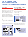
ZRU INSTALLATION GUIDE
UNDER FLOOR HEATING TO SINGLE AREAS
(UNDER 30m2) OR CONSERVATORIES
UTILISING THE POLYPIPE ZONAL REGULATION UNIT* (ZRU) PB970028
Introduction
The Polypipe Zonal Regulation Unit (ZRU) allows single rooms
and extensions up to 30m² to be connected to an existing heating
system without time consuming and expensive hydraulic and
electrical alterations. When connected to an existing radiator
heating system the ZRU converts the water flow and temperature
to that suitable for underfloor heating.
• The ZRU boosts flow, ensuring that the underfloor system
is not reliant on existing pump pressure
• Water is thermostatically blended to provide the ideal safe
flow temperature control
• Sensors within the unit ensure operation only occurs when
heat is available from the existing heating system
• Room thermostat regulates air temperature in the space
being heated
• Although designed to be surface mounted in the heated area,
the ZRU can be positioned elsewhere within the property
• The ZRU can be used in both domestic and commercial buildings
• As the ZRU thermostatically controls water temperature the
unit can also be used where low surface temperature heating
by radiators is required
Connections to the existing
wet heating system
The pipe work connections to the ZRU are for 15mm diameter
pipe and the ZRU should not be connected to the system from
any pipe smaller than 15mm.
A small number of boilers can be affected hydraulically
by the use of a second pump in the system.
NOTE: Check with the boiler manufacturer to ensure
compatibility with the ZRU.
The preferred connection to the ZRU is to the main flow and
return pipe work of a 2 pipe system, i.e. typically from 22mm
distribution pipe work. However it can also be connected to
the nearest existing radiator.
Pipe connection to operate underfloor heating
at the same time as the boiler
Connection
from main
distribution
pipe work
Pipe Connections at ZRU
Provision for two heating circuits is provided on the ZRU. If only
one circuit is required, blank off the unused ports with spigot
blanking plugs.
Elbows should be used underneath the ZRU to exit pipe from
the floor and a small section of floor plate should be cut away
to allow the pipes to exit the floor at the correct position.
These elbows should be covered with Polystyrene prior to, and during
screeding to allow for future excavation if required. Alternatively they
can be enclosed within a Polyplumb Junction Box.
Zonal Regulation Unit (ZRU)
Thermostatic
Blending
Valve
Pump
For 3rd
circuit if
required
Connection
from nearest
radiator
The diagram above shows the ZRU connected to operate with the
boiler on / off firing. Due to the quick response of low mass systems
(Overlay™, Overlay™ Lite, MHP, etc) this is likely to be suitable.
Using this method for solid floor installations may require the
timings of the existing heating to be altered to allow the
underfloor heating system to reach comfort temperature.
If the room is to be controlled independently of the existing
central heating system, a zone valve needs to be installed
between the boiler and the ZRU.
Pipe connection to operate ZRU / underfloor
heating independently
Programmable room thermostat
Zone
valve
to
underfloor
heating
Zone valve
to radiator, etc
Heating Heating
Return Flow
Pipe Thermostat
*Patent pending
UFH
Returns
Underfloor
Heating Flows
(fig. 1)
Connection
from main
distribution
pipe work
Operational Sequence
Installation of ZRU
1.Heating water from the existing system is pumped through the
heating flow by the existing heating pump and returns through
the heating return forming a simple loop.
2.The pipe thermostat senses that heating water is available
i.e. when the main heating system is on and sends a live signal
to the pump.
NOTE: The water temperature must be 45°C to operate the unit.
3.If the room thermostat (if fitted) is also calling for heat the
pump operates.
4.A mixture of heating flow and underfloor heating return water
is drawn through the thermostatic blending valve at the correct
temperature and pumped into the underfloor heating.
5.As the room reaches temperature, the room thermostat
will break the live signal to the pump and stop the pump
from operating.
6.As the boiler shuts down and the main heating flow cools,
the pipe stat will break the live signal to the pump and stop
the pump from operating.
The ZRU can be positioned either in the room where the underfloor
heating is installed or in an adjacent area, 100mm from the
finished floor level to allow for pipe connections. Tape fixing
template to wall showing fixing positions. Drill wall and fix plugs.
Zonal Regulation Unit (ZRU)
Thermostatic
Blending
Valve
Pump
For 3rd
circuit if
required
Fitting the ZRU
Step 1: Screw unit to wall.
Connecting the ZRU
Step 2: Connect heating pipe work via an isolation valve.
Step 3:Connect underfloor heating circuit(s) using an isolation
valve. Use tees and spigot elbows to form connections
for 3rd circuit systems.
Step 4:Connect mains wiring (as diagram below) via a fused spur.
Filling (All Systems)
The pipe system should be filled, usually by means of a hosepipe,
prior to screeding or floor covering if the ZRU is to be installed at
a later time than the underfloor circuit, e.g. to allow for plastering,
etc. Pipework should be temporarily capped and remain full of
water preferably at pressure. Special precautions are necessary
if the pressure testing is to take place in sub-zero temperatures.
Wiring Details
Heating Heating
Return Flow
UFH
Returns
Underfloor
Heating Flows
Pipe Thermostat
(fig. 1)
Performance & safety data info
This appliance can be used by children aged from 8 years and
above and persons with reduced physical, sensory or mental
capabilities or lack of experience and knowledge if they have been
given supervision or instruction concerning use of the appliance
in a safe way and understand the hazards involved. Children shall
not play with the appliance. Cleaning and user maintenance shall
not be made by children without supervision.
All electrical installations must be in accordance wit the latest
version of the relevant legal requirements.
The ZRU must be installed with means for disconnection from the
supply mains having a contact separation in all poles that provides
full disconnection under overvoltage category III. The means
for disconnection must be incorporated in the fixed wiring in
accordance with the wiring rules.
If in any doubt, contact a qualified electrician. The wiring diagram
is as shown.
NOTE: The water temperature must be 45°C to operate the unit.
Room Thermostat (example) Not supplied.
1.Maximum ambient air temperature is 60°C at 95°C
fluid temperature.
2.Pressure rating is PN6.
SL
L
N
E
L
N
E
Remove link if
using room stat.
Mains
(fused spur)
3 amp
ZRUINST
BOILER FLOW
MIXING
VALVE
VENT
80mm MINIMUM WALL CLEARANCE
FOR MIXING VALVE ADJUSTMENT
BOILER RETURN
WIRING
MODULE
HEATING LOOP(S) RETURN
PUMP
SCREW FIXING POSITIONS
HEATING LOOP(S) FLOW