1
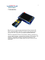
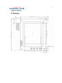
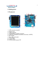
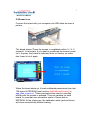
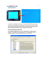
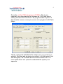
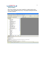
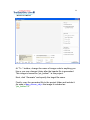
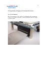
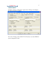
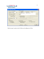
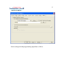
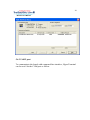
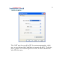
Blue Screen
User Manual
v1.00
2
Blue Screen Manual
1. Introduction
Blue Screen is a touch screen development board comes with
NXP’s powerful ARM7 LPC2378, resistive-type-2.8-inch touch
screen TFT LCD, micro-SD card socket and 8kB EEPROM.
With full of peripheral drivers and advance software modules e.g.
screen object manager, command line interface, SPI interface, I2C
interface. The board is suited for all levels of developer. Any
technical problem about coding, please feel free to post it in our
webboard.
3
Blue Screen Manual
2. Features
Hardware
- 240x320 pixels TFT LCD with touch screen
- NXP’s ARM7 LPC2378
- Micro-SD card socket (connected via SPI interface) support up
to 2GB capacity (High capacity: ‘HC’ type not supported)
- On board 8kB EEPROM (the last 128 bytes are reserved for
screen calibrated parameters)
- 1 port ThaiEasyElec’s module connector consisting of SPI and
UART signals from MCU
- UART connector for command line interface and in-system
programming (TTL 3.3v with 5v tolerant)
- 16 ports GPIO
- Mini-B USB connector (the board is powered from USB
connector)
Software
Demonstrating application
- MP3 player with graphic user interface (ThaiEasyElec’s
VS1011 Module required)
Command line interface software module
- Show image from SD card
- SD card commands e.g. change directory, list, open read, open
write
- Audio related commands e.g. play, pause, increase, decrease
volume
Screen object software module
- Design your screen with object oriented method, the running
background software will manage which object should be operated
Low level drivers
-
LCD driver
Touch screen controller (AD7843) driver
Serial port
SPI interface
I2C interface
4
Blue Screen Manual
3. Requirement
- USB cable (type A to mini-B) for supplying the board
- ThaiEasyElec’s VS1011 module (optional) for MP3 player
application (free earphone)
- ThaiEasyElec’s USB to serial and cable (optional) for command
line interface
- Stylus (optional)
- Micro-SD card (optional)
- Programmer/Debugger (optional) ULink and mini N-Link are
supported
VS1011E Module
Mini SD Card
USB mini B to Serial
Stylus
mini N-link ARM USB JTAG
5
Blue Screen Manual
4. Drawing
6
Blue Screen Manual
5. Getting start
5.1 Peripherals
1. USB connector (mini-B)
2. Reset button
3. JTAG connector
4. ThaiEasyElec’s module connector
5. Console (command line interface connector, UART0)
6. ISP Jumper
7. Micro-SD card socket
8. 16-bit GPIO
9. 4 green LEDs
10. 2.8-inch touch screen LCD
7
Blue Screen Manual
5.2 Power it on
Connect the board with your computer via USB cable as seen in
picture.
The board shows “Press the screen to recalibrate within 3 (..2..1)
seconds”. In this state, if you want to recalibrate the screen, press
on it. Anyway, the board is calibrated from our factory so users
don’t need to do it again.
When the board starts up, it loads calibrated parameters from last
128 bytes of EEPROM (see function AppCalibrateScreen() in
app_blue_screen.c). These parameters are used to calculate
which point the screen is pressed. They are variable on each
board. In case that user overwrites some of these data in
EEPROM. At the starting up, the calibration state (picture below)
will show automatically without waiting.
8
Blue Screen Manual
In order to recalibrate the screen, there would be 25 points on the
screen to be pressed. For each point, user needs to touch it twice.
For accuracy, please touch it slowly and a stylus should be used.
When finishing, the MP3 Player screen will be shown.
5.3 Creating project with Keil
The board is supplied with codes. Users have to make project
yourself. This guide is an example for Keil. Firstly, you have to
create a project. And select the device as “LPC2378”
9
Blue Screen Manual
Secondly, set the XTAL frequency as 20 MHz. This is very
important; one downloading the firmware via JTAG with wrong
setting will cause the board not to be programmable anymore. If
this situation occurs, one way to recover is to program it with Flash
Magic.
Thirdly, replace the LPC2300.s file with the one you got from our
website. And then add all other source files (.c) in the project. And
also add group “efs” and add all source files in folder “efs”. For
more detail about “efs” (stand for embedded file system) see
appendix.
10
Blue Screen Manual
After these settings, the project should be compiled without any
errors (some warnings may occur). The project workspace should
be seen as below.
11
Blue Screen Manual
5.4 Source files description
Header files (only important files are shown)
1. hw_blue_screen.h : define hardware, for example : TC_CS is at
port 2.2
#define TC_CS_DPRT
#define TC_CS_PRTS
#define TC_CS_PRTC
#define TC_CS_PIN
FIO2DIR
FIO2SET
FIO2CLR
2
DPRT : direction port
PRTS : port set
PRTC : port clear
PIN : pin number in the port
These may look awkward, but it’s very easy to change some
pins.
2. app_config.h : this file is used to configure many parameters
various on each project. Header file including are in this file.
And this file is included in most of source file. So which
declaration shared on more than one source file should be
declared on this file. This file also has function declarations
from app_blue_screen_demo.c
3. All other header files are subjected to declare functions only.
Source files (only important files are shown)
1. main.c : background functions are here including timer interrupt
service routine (T0_IRQHandler()), i/o initialization (io_init()). In
case that user need to use more peripherals, PINSEL may be
set in io_init(). Notice that AppInit() and AppRun() are called
from main(), user application may be modified (or recreate)
using these functions.
12
Blue Screen Manual
2. app_blue_screen.c : most of application are here except the
graphic user interface which is in app_screen_obj.c
3. screen_obj.c : this is the code running in the background of
screen object management. From the AppScanPen() in
app_blue_screen.c, the screen position and the pen status are
send to ScrObjDo(). This point is called “global position”
because it refers the hold screen. In ScrObjDo(), each object
are determined whether the screen position is in its area
considering from its origin and its size. Then “.do()” of targeted
object will be processed with “local position” got from minus of
global position and the object’s origin.
4. app_screen_obj.c : in this file, each object’s parameter are
defined here including origin, horizontal and vertical size, do()
and draw() function and etc. A part of code from this file is
shown below.
#define SO_VOLUME
0 // (1)
so_obj[SO_VOLUME].hsize = 16; // (2)
so_obj[SO_VOLUME].vsize = 108; // (3)
so_obj[SO_VOLUME].horigin = 284; // (4)
so_obj[SO_VOLUME].vorigin = 20; // (5)
so_obj[SO_VOLUME].stat = SO_ST_ON; // (6)
so_obj[SO_VOLUME].val = 60; // (7)
so_obj[SO_VOLUME].draw = volume_draw; // (8)
so_obj[SO_VOLUME].do_ = volume_do; // (9)
so_obj[SO_VOLUME].task100ms = volume_task100ms;//
(10)
so_obj[SO_VOLUME].is_white = volume_is_white; // (11)
Line (1) is to dedicate that, for this screen (MP3 player screen).
The volume bar is the number 1 object.
Line (2) and (3) define width and height of the object
respectively.
13
Blue Screen Manual
Line (4) and (5) define horizontal and vertical origin of the
object.
Line (6) enables this object.
Line (7) sets default value of the object (value may be variable
for each type of object).
Line (8) – (11) set the addresses of these function to there
corresponding function.
Note that “so_obj” is structure type variable. User may change
its parameter when need. So in case that user designs more
than one screen in an application. The array “so_obj” can be
redefined again and again for each screen.
For more detail about “so_obj” please see in screen_obj.h.
5.5 Image generating
In the MP3 player application, most of images seen on the screen
are generated from JPEG files or Bitmap files with the software
called “bmp2h_conv”. The last version is 5.1 allows bigger size of
image. This part of manual shows step by step how to implement
these pictures into your project.
Firstly, create your image using Paint or whatever you like.
Secondly, run bmp2h_conv and load your image. The default
configurations of this version are supported for this type of LCD.
There is nothing to be worried about these options.
14
Blue Screen Manual
At “To :” textbox, change the name of image code to anything you
like or you may change it later after the header file is generated.
This image is named as “pic_button1” in this project.
Next, click “Generate” and specify the target file name.
Finally, copy the generated file to the project folder and include it.
As seen in app_screen_obj.c this image is included as
“pic_button1.h”.
15
Blue Screen Manual
In order to display this image on the screen, see function
bt1_draw() in app_screen_obj.c. First the area is filled with a
rectangular. Then it’s overfilled with pic_button1 image with the
offset pointer at
so_obj[SO_BT1].val*(so_obj[SO_BT1].hsize*so_obj[SO_BT1].vsiz
e)
with value of “val” at 0-3, four styles button can be displayed
occasionally.
Notice about “TS_MODE_NORMAL” in function bt1_draw(). This is
mode of displaying something on the screen. See appendix for
more detail.
16
Blue Screen Manual
5.6 Programming, Debugging and Command line interface
5.6.1 JTAG Interface
Blue Screen supports JTAG interface for debugging and programming.
Connect JTAG cable so the pin#1 is on the same side with reset switch,
see picture below.
17
Blue Screen Manual
For Keil’s software, on the target’s option select ‘Debug’ and configure
the flash programmer as follow.
Also select ‘Settings’ and set MAX JTAG Clock not over than 200kHz if
you are using mini N-Link.
18
Blue Screen Manual
Back to target’s option select Utilities and configure as follow.
19
Blue Screen Manual
Select setting and add programming algorithm as follow.
20
Blue Screen Manual
5.6.2 UART port
To communicate the board with command line interface, HyperTerminal
can be used. Set the COM port as follow.
21
Blue Screen Manual
This UART port also served for ISP (In-system programming), which
user can use software like Flash Magic to program the MCU. To do this,
place a jumper on J1 and then press reset. Now the MCU should starts
with ISP boot loader.
22
Blue Screen Manual
Appendix
1. TS_MODE (refers to tslcd_elt240320tp.h)
TS_MODE is display mode used in functions start with TSLCD.
Now there are 3 modes available, TS_MODE_NORMAL,
TS_MODE_INVERSE and TS_MODE_FULL.
- TS_MODE_NORMAL : To displaying a circle or some images
having white background, user may want this white background to
be transparent. Using this mode, all pixel having value 0xFFFF will
considered as ‘background’ and it will be display as read-back
color. The example of this mode displaying is the volume bar.
There you can see blue background instead of white.
- TS_MODE_INVERSE : As it’s name “inverse”. The circle or
rectangular drawn will have inverse color to the old color. Color
parameter sent to the function will be ignored.
- TS_MODE_FULL : In case of showing a text message again and
again in the same area. You need the use this mode as the blank
space will be filled with background color. Anyway, displaying an
image (TSLCDShowPic2()) with this mode all color from original
image code will be display including white color.
Note that a rectangular doesn’t have blank space; in this case
TS_MODE_NORMAL and TS_MODE_FULL have same effect.
2. Pen status (refers to app_config.h)
Pen status or in code “pstatus” means the current state of pen.
This is useful parameter sent to ScrObjDo(). There are 4 available
statuses:
23
Blue Screen Manual
- PST_NOTFOUND : means that the screen is not pressed.
- PST_DOWN : occurs once the screen is pressed.
- PST_HOLD : occurs continuously while the screen is pressed.
- PST_UP : occurs once the screen is released.
3. Embedded file system library (EFSL)
Embedded file system library using in this application is free library
downloadable from http://sourceforge.net/projects/efsl/ . It’s limited
to SPI only (LPC23xx’s MCI is not supported). It’s very easy to port
it to your existing hardware. AVR, NXP’s ARM7, and some other
platform have already had example.
In this application lpc200_spi.c is modified from original code. It is
the bridge between our SPI library and EFSL. Other files is also
modified (some lines are commented) to decrease warnings and
errors.