1
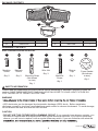
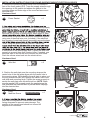
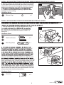
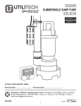
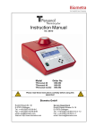
ITEM #0611551, #0611550
Utilitech & UT Design® are registered trademarks
of LF, LLC. All Rights Reserved.
LED MOTION ACTIVATED
FLOOD LIGHT
MODEL #SE1036-BP2-02LF0-U,
SE1036-WH3-02LF0-U
Français p. 10
Español p. 19
ATTACH YOUR RECEIPT HERE
Serial Number
Purchase Date
Questions, problems, missing parts? Before returning to your retailer, call our customer
service department at 1-866-994-4148, 8 a.m. - 6 p.m., EST, Monday - Thursday,
8 a.m. - 5 p.m., EST, Friday.
AB14519
1
Lowes.com
PACKAGE CONTENTS
D
A
B
PARTS
A
B
DESCRIPTION
LED Head
Sensor Arm
C
QUANTITY
2
1
PARTS
C
D
DESCRIPTION
Sensor Head
Wall Plate
QUANTITY
1
1
HARDWARE CONTENTS
Note: Hardware shown actual size.
BB
Machine
Screw
Machine
Screw
Qty. 2
Qty. 2
CC
DD
EE
FF
GG
GND
FRONT
AA
Wire Nut
Mounting Strap
(Not shown
to size)
Qty. 3
Long
Machine
Screw
Silcone
Cap
Qty. 1
Foam Gasket
(Not shown
to size)
Qty. 1
Qty. 1
Qty. 1
SAFETY INFORMATION
Please read and understand this entire manual before attempting to assemble, operate or install the
product. SAVE THESE INSTRUCTIONS IN A LOCATION CLOSE TO YOUR LIGHT FIXTURE SO
YOU CAN REFER TO THEM AT A LATER TIME.
WARNING
the new one.
• LED electronics can be damaged by electrostatic discharge (ESD) shock. Before installation,
discharge yourself by touching a grounded bare metal surface to remove this hazard. To avoid damage,
do not remove the clear lens over the LED module.
CAUTION
• DO NOT USE THIS FIXTURE WITH A DIMMING CIRCUIT. If you currently have dimmer controls, you
will need to remove them and replace them with regular electrical switches. If you have a three-way
dimmer, you will have to replace it with a regular three-way switch. If you are unfamiliar with electrical
2
Lowes.com
SAFETY INFORMATION
IMPORTANT SAFETY INSTRUCTIONS
1. Turn power OFF before installing or servicing.
3.
4.
5.
6.
7.
Do NOT remove the protective LED lens.
Do NOT look directly at lighted LEDs for any length of time.
Do NOT leave bare wires exposed outside the wall canopy enclosure.
Electrical requirements: 120 V AC, 60 Hz., 0.31A. Minimum 90° supply conductors.
Suitable for wall or eave mounting onto recessed or round surface mounted electrical boxes rated for
wet locations. Not suitable for ground mount electrical boxes.
8. Do NOT allow the sensor head to touch the LED head housing. Maintain at least 1 in. spacing
between the LED heads and the sensor head.
9. For proper operation and protection against water damage, the motion sensor adjustment controls
MUST be facing downward.
10. Do NOT mount below 5 ft.
11. Do not mount near other light sources that can compromise the dusk to dawn sensor.
12. This device complies with Part 15 of the FCC rules. Operation is subject to the following two
conditions: (1) This device may not cause harmful interference, and (2) this device must accept any
interference received, including interference that may cause undesired operation.
PREPARATION
Before beginning installation of product, make sure all parts are present. Compare parts with package
contents list and hardware contents list. If any part is missing or damaged, do not attempt to install the
product.
Estimated Assembly Time: 45 minutes.
Tools Required for Assembly (not included): Phillips screwdriver and silicone adhesive caulking.
pools or bodies of water, or trees/bushes that move in the wind. All of these may trigger the motion
sensor security light and may be disruptive to the intended operation of the light. Do NOT install near
other sources of light. The other light sources can fool the dusk to dawn sensor into thinking it is daylight.
INSTALLATION INSTRUCTIONS FOR ROUND SURFACE MOUNT ELECTRICAL BOXES
electrical box that has more than two wire leads, mark the wires to keep track of the correct ones to use.
1. Pull the supply wires out of the electrical box. Using
box, secure the mounting strap (CC) to the electrical
box, making sure that the side marked “FRONT” is
facing out.
Hardware Used
AA
BB
CC
1
GN
D
FR
Mounting Strap
GND
FRONT
ON
T
x2
Machine Screws
CC
x1
3
Lowes.com
AA
INSTALLATION INSTRUCTIONS FOR ROUND SURFACE MOUNT ELECTRICAL BOXES
2. Remove the protective paper barrier from the adhesive
face of the foam gasket (GG). Trace the supply wires through
the openings in the gasket and adhere the gasket to the
mounting strap and outer edge of the round surface mount
electrical box.
Hardware Used
GG
Foam Gasket
2
GN
D
GG
FR
ON
T
x1
properly grounded. If unfamiliar with the methods of properly
3
DD
electrical box is made of plastic and/or has a green or bare
GN
D
the electrical box ground wire should be connected together
using one of the small wire nuts (included). If the electrical
box is made of metal and already grounded, secure the bare
FR
O
NT
GN
D
FR
“GND” using the green grounding screw. Connect the
DD
ON
T
is connected to the white supply lead. Tighten the wire nuts
properly to prevent them from coming loose. If needed, use
electrical tape to secure the wire nuts onto the wire leads.
Push the excess wires back into the electrical box.
Hardware Used
DD
Wire Nut
x3
4
4. Position the wall plate over the mounting strap so the
center hole of the wall plate aligns with the center hole in
the mounting strap. While holding the wall plate in place, put
the long machine screw (EE) through the center hole of the
wall plate and mounting strap. Tighten the screw properly to
secure the wall plate onto the electrical box. NOTE: Make
sure the gasket (GG) properly seals the gap between the
wall plate and the electrical box to prevent water seepage
into the electrical box.
Hardware Used
EE
Long
Machine Screw
x1
EE
5
45°
head with the adjustment controls and drain holes
facing downward to prevent water damage. The
position of the sensor head should not exceed 45
degrees from horizontal.
45°
45°
4
Lowes.com
45°
INSTALLATION INSTRUCTIONS FOR ROUND SURFACE MOUNT ELECTRICAL BOXES
6. Restore power to the electrical box at the circuit breaker
or fuse panel. Make sure the wall switch that controls the
electrical box for your security light is returned to the “ON”
position and check that your light is functioning properly.
6
1
(FF) into the mounting screw opening to prevent water
seepage into the housing.
Hardware Used
FF
x1
Silicone Cap
INSTALLATION INSTRUCTIONS FOR RECESSED ELECTRICAL BOXES
electrical box that has more than two wire leads, mark the wires to keep track of the correct ones to use.
1. Pull the supply wires out of the electrical box. Using
box, secure the mounting strap (CC) to the electrical
box, making sure that the side marked “FRONT” is
facing out.
Hardware Used
AA
BB
CC
1
CC
x2
Machine Screws
AA
Mounting Strap
GND
FRONT
x1
be properly grounded. If unfamiliar with the methods of
electrician. A green copper ground wire is pre-attached
2
DD
GND
NT
FRO
or has a green or bare copper grounding wire inside, the
should be connected together using one of the small
wire nuts (included). If the electrical box is made of metal
ground wire to the mounting strap marked “GND” using the
green grounding screw. Connect the supply leads from the
GND
FRO
NT
DD
to the white supply lead. Tighten the wire nuts properly to
prevent them from coming loose. If needed, use electrical
tape to secure the wire nuts onto the wire leads. Push the
excess wires back into the electrical box.
Hardware Used
DD
Wire Nut
x3
5
Lowes.com
INSTALLATION INSTRUCTIONS FOR RECESSED ELECTRICAL BOXES
3. Position the wall plate over the mounting strap so
the center hole of the wall plate aligns with the center
hole in the mounting strap. While holding the wall plate
place the long machine screw (EE) through the center
hole of the wall plate and mounting strap. Tighten
the screw properly to secure the wall plate onto the
mounting surface.
Hardware Used
EE
Long
Machine Screw
3
EE
x1
4
head with the adjustment controls and drain holes
facing downward to prevent water damage. The
position of the sensor head should not exceed 45
degrees from horizontal.
45°
45°
45°
5. Restore power to the electrical box at the circuit
breaker or fuse panel. Make sure the wall switch that
controls the electrical box for your security light is
returned to the “ON” position and check that your light
is functioning properly.
5
If the light is functioning properly, use silicone adhesive
caulking (not included) to caulk the gap between the
wall plate and the mounting surface to prevent water
seepage into the electrical enclosure.
6. Fit the silicone cap (FF) into the mounting screw
opening to prevent water seepage into the housing.
6
1
Hardware Used
FF
Silicone Cap
x1
6
Lowes.com
45°
OPERATING INSTRUCTIONS
to-dawn sensor. The dusk-to-dawn
sensor disables the motion detector during daylight hours and only allows the motion sensor to activate
the light after dark. The security light will not activate during daylight hours regardless of whether it sees
motion or not.
1. The slide switch on the bottom surface of the motion
sensor has four settings:
TEST-1-5-10
In the “TEST” position, the motion sensor will turn
the lights on for 40 seconds after power is applied to
The lights will come on for 40 seconds regardless
of whether there is motion or not, and regardless of
whether it is day or night. Leave the slide switch in the
“TEST” setting and adjust the sensitivity by crossing in
the path of the sensor. The light will come on only if it
senses movement. Once movement stops, it will turn
off in 5 seconds.
2. There is also a rotary knob on the bottom of the
motion sensor labeled:
SENSITIVITY
Rotating this knob clockwise raises the sensitivity of
the motion sensor for up to 60 ft. of distance.
Rotating the knob counterclockwise lowers the
sensitivity down to as close as 5 ft. It may be
necessary to adjust the “SENSITIVITY” knob several
particular installation. NOTE: The higher sensitivity
level for longer distances (up to 60 ft.) increases the
likelihood of false triggering. For maximum range
(with power) for at least 48 hours.
3. The 180° coverage of the motion sensor is
measured side to side. Therefore, the sensor will better
rather than motion coming straight at the sensor
(in-and-out). Adjust the motion sensor head so that it
sees motion moving across the coverage area. Make
sure the sensor head is positioned with the front lens
facing slightly downward (5°-15 angle) to prevent
water accumulation on the sensor head. Do not aim
the motion sensor at a body of water, bushes or plants
cars, etc., as this will trigger the motion sensor. NOTE:
If the sensor arm becomes loose, it will not hold the
sensor head at the proper angle. Readjust the sensor
head and tighten the joint screw on the sensor arm.
4. Each light head can be adjusted at the sensor arm
7
OPERATING INSTRUCTIONS
5
operation and sensitivity, move the switch to the “1,
5, or 10” position. Each of these positions allows the
these settings indicates the time frame that the light
will remain on after detecting motion. If set for the “1”
setting, the lights will come on for 1 minute after
detecting motion, and then will go off and return to the
AUTO motion sensor mode. When set for “5”, the lights
will remain on for 5 minutes after detecting motion. If
set for “10”, the lights will remain on for 10 minutes
after detecting motion. If motion is continuously
detected during the lights’ “ON” cycle, the lights will
remain on until the motion ceases.
6. To be able to manually turn on the security light from inside your home, toggle the wall light switch OFF
and ON within 2 seconds. The security light will turn on and stay on for approximately 8 hours, or until the
dusk-to-dawn sensor detects light in the morning. Once the dusk-to-dawn sensor detects light, the manual
“ON” mode will automatically go back to its original settings of the AUTO motion sensor mode. At any point
while in manual “ON” mode, return to the AUTO motion sensor mode by toggling the wall light switch OFF
and ON again within 2 seconds.
SECURITY LIGHT OPERATION
MODE
SLIDE SWITCH
WALL SWITCH
SENSITIVITY A
Test Mode
Test
Turn on
Any setting
AUTO Motion Sensor
Mode
1, 5, or 10 Minutes
ON
Any setting
Manual “ON” Mode
1, 5, or 10 Minutes
Any setting
Return to AUTO Motion
Sensor Mode
1, 5, or 10 Minutes
Toggle OFF and ON
within 2 seconds
Toggle OFF and ON
within 2 seconds
Any setting
CARE AND MAINTENANCE
NOT
use solvents or cleaners containing abrasive agents. When clean
TROUBLESHOOTING
• Extreme hot or cold weather could affect the performance of the built-in sensors that detect body heat.
Certain winter clothing can shield a person’s body heat from the sensor during extreme cold weather.
During extreme hot weather, the sensor may not be able to distinguish the difference between normal body
temperatures and the surrounding high temperatures. The sensor will begin working normally once weather
conditions return to normal.
PROBLEM
POSSIBLE CAUSE
CORRECTIVE ACTION
Light does not come on
at night when motion
is detected.
1. No power is being
1. Check that circuit breaker and/or wall
switch power is on.
2. Another light source is
causing the security light
to think it is daylight.
2. Turn off surrounding lights and/or re-aim
the sensor head.
came loose.
A
reconnect any loose wiring.
8
2814INSSE1036
Lowes.com