1
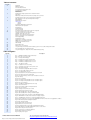
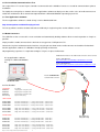
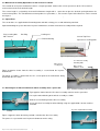
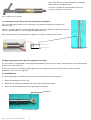
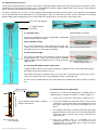
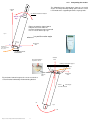
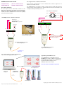
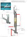
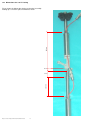
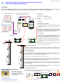
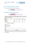
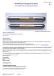
Geotechnical Instrumentation
In-Place-Inclinometer Installation Manual
SDI-12/RS485 Digital Network Device
Vertical I-P-I Chain Operations Only
Last updated Nov 2013
Keynes Controls In-place-inclinometer Installation Guide
1
Table of contents
Page No
3
Introduction
Warranty Provisions
Successful Measurements
4
Pre-installation Communications Test
Free Applications Software
Media Converters
Part Numbers
5
Mechanical Assembly Operations for the Vertical I-P-I Chain
Spacer Bars
Attaching the In-Place-Inclinometer wheel assembly onto a spacer bar
6
Fastening the spacer bar to the top of the In-place-inclinometer
Minor adjustments to the spacer bar alignment and length
Rod End Baring
7
Digital Network Connection
Network Types
SDI-12
RS-485
Securing the digital network signal cable
Network Connection Operations
8
Axis alignment
Top Mounting Cap
Sensor Connection
9
Securing the In-place-inclinometer chain to the casing tube
10
Sensor Connection Pin-outs - glass seals
Lumberg Connector Pin-outs - Extension cable
Standard signal cable colour codes
Advice for successful measurement operations
Advice for selecting the sensor chain location
Power Supply Rating
11
Interpreting the results
12
Single Sensors or Interfaces Connection
Multiple Sensors or Interface Connection
Typical Q-Log Panel Meter Screen
13
Cable Routing
14
Physical Dimensions
15
Dimensions for 3 m I-P-I string
16
Long Term In-place-inclinometer chain monitoring systems for n-accessible underground locations.
17
Sensor Installation into a flooded I-P-I Casing
18
Long Term Deployment - damp environment - additional waterproofing
Table of Figures
Page NO
Description
3
Fig 1
- KEYNES CONTROLS In-place-inclinometer
4
Fig 2 - Basic I-P-I test system setup
5
Fig 3 - I-P-I Spacer Bar with plug
5
Fig 4 - I-P-I Spacer bar top piece mount position
5
Fig 5 - I-P-I Wheel assembly mounted on a sensor
5
Fig 6 - I-P-I Wheel assembly mounted on a sensor
5
Fig 7 - I-P-I wheel assembly
6
Fig 8 - Complete I-P-I sensor assembly
6
Fig 9 - Securing the spacer bar to the top of the sensor
6
Fig 10 - Spacer bar locking nut
7
Fig 11 - I-P-I Chain Assembly with network connection
7
Fig 12
7
Fig 13 - Un-sealed network connector
I-P-I Sensor with network connectors
7
Fig 14 - Sealed network connector making a waterproof connection
7
Fig 15 - Connection of the I-P-I to a data logger
8
Fig 16 - I-P-I chain showing a common sensor orientation for all sensors.
8
Fig 17 I-P-I Casing
8
Fig 18 - Sensor orientation
8
Fig 19 - I-P-I casing showing the different sensor orientation options
9
Fig 19 - I-P-I casing showing the different sensor orientation options
9
Fig 20 - Top cap securing bolt
9
Fig 21 - I-P-I Wheel assembly alignment to the casing
9
Fig 22 - Measurement Points
10
Fig 23 - Top mounting cap with securing bolt attached
10
Fig 24 - Sensor Connections
10
Fig 25 Lumberg Connector Pin-outs - Female
10
Fig 26 Lumberg Connector Pin-outs - Male
11
Fig 27 - Understanding Axis for I-P-I chain deployment
11
Fig 28 - Understanding Axis for Ceiling / Horizontal Support
12
Fig 29 - In-place-Inclinometer connection to an RS-485 Digital Network
12
Fig 30 - USB-RS485-Pro media converter installed on a laptop computer.
12
Fig 31 - USB-RS485-Pro connection to a single I-P-I RS485 model sensor
12
Fig 32 - In-place-inclinometer test system using USB-RS485-Pro media converter and Q-Log applications software
13
Fig 33 - Cable Routing Guide & Safety bar installation
14
Fig 33 - Rod end baring spacing
14
Fig 34 - Standard I-P-I sensor dimensions
15
Fig 35 - Dimensions for a 3 m I-P-I string
16
Fig 36 - PC Data Acquisition system using isolated RS-485 I-P-I Chain
17
Fig 37 - Water filled I-P-I chain with individually wired sensors to the surface.
18
Fig 38 Dow Coning DC4 Silcone Grease,
18
Fig 39 I-P-I Connector on submerged water test
18
Fig 40 - Mated Lumberg I-P-I Connector
18
Fig 41 - Injecting silicon grease
In-Place-Inclinometer User Manual
Keynes Controls In-place-inclinometer Installation Guide
The user manual can be downloaded at
http://www.aquabat.net/downloads/UserManual-IPIv4.pdf
2
1.0 Introduction
The following manual details the instruction to follow to assemble the Keynes Controls In-place-inclinometers to form a vertical
measurement chain.
This manual is meant as a guide only and some prior knowledge on the use of In-place-inclinometers is expected.
Where possible Keynes Controls have endeavoured to make sure the parts only fit together in a single way in order to avoid in
confusion in any measurement operation.
All of the inclinometers described in this manual use a digital network for data communications. All of the sensors are intelligent
and undertake any measurement operation internally within the device,
Full User manual for the programming of this device is available for free download from the Keynes Controls Web site and can
be found at http://www.aquabat.net.
1.1 Recommended Calibration Period
For best results Keynes Controls recommends that the sensors are re-calibrated on an annual basis.
1.2 Mounting Bolts
All metal parts making up the In-place-inclinometer are constructed from stainless steel. The mounting bolts are M6 and also of
stainless steel.
1.3 Successful Measurements
For a successful measurement system to be created the in-place-inclinometers should not be subject to mechanical shock
during installation. They shall be located away from any sources of local vibration and use the correctly rated power supply.
Sensor Top
Fit wheel
assembly
here
Secure spacer
bar here
Fig 1 - KEYNES CONTROLS In-place-inclinometer
Sensor Bottom
2.0 WARRANTY PROVISIONS
Keynes Controls Ltd . warrants the I-P-I range of tilt sensors for one year from date of purchase by the end user against defects in materials and workmanship
under normal operating conditions.
To exercise this warranty contact Technical Support at the phone or e-mail address listed below
for a return material authorization (RMA) and instructions. Complete warranty provisions are posted on our website at http://www.aquabat.net
The information in this document is subject to change without notice. Keynes Controls Ltd. has made a reasonable effort to be sure that the information contained
herein is current and accurate as of the date of publication.
Keynes Controls Ltd. makes no warranty of any kind with regard to this material, including, but not limited to, its fitness for a particular application. Keynes Controls
Ltd will not be liable for errors contained herein or for incidental or consequential damages in connection with the furnishing, performance, or use of this material.
In no event shall Keynes Controls Ltd . be liable for any claim for direct, incidental, or consequential damages arising out of, or in connection with, the sale,
manufacture, delivery, or use of any product.
HOW TO CONTACT US
Important Note
Technical Support
Keynes Controls Ltd
Riseley Business Park
Riseley
Berkshire, RG7 1NW
This product contains sensitive electronics and can be
damaged by physical shock.
Under no circumstances allow the In-place-Inclinometer
to be dropped.
Tel: (0044) 118 327 6067
E-mail: [email protected]
2.1 FIRMWARE & SOFTWARE UPGRADES
The In-place-inclinometer is firmware up-grade able. Contact Keynes Controls Ltd. for details.
If you suspect that your In-place-inclinometer is malfunctioning or requires re-calibration and repair is required then contact us.
you can help assure efficient servicing by following these guidelines:
Keynes Controls In-place-inclinometer Installation Guide
3
3.0 Pre-installation Communications Test
On receipt of the I-P-I sensors Keynes Controls recommends that the individual sensors are tested for communications prior to
installation.
To simplify the testing Keynes Controls offer free applications software to display test data, and a series of media converters to
enable the inclinometers to be attached and operated from a Microsoft Windows Operating System PC.
3.1 Free Applications Software
The free applications software is called Q-Log. It can be downloaded from
http://www.aquabat.net/QLOGFree/qlogv2.html
The Q-Log software enables the data to be observed directly in engineering units and to calibrate sensors.
3.2 Media Converters
The USB-Pro version sensors offer sensor excitation and automatically loading software drivers to make operation as simple as
possible.
Simply install the media converter for the desired sensor type into a USB port on a PC.
Connect the In-place-inclinometer to the interface using the pin-out shown on the media converter and read the tilt data back
into the applications software in a Windows friendly operating environment,
No programming experience is required to configure a Keynes In-place-inclinometer.
Additional information for the USB media converters can be found at
Q-Log applications software
running on a Microsoft Windows
PC
Model: USB-SDI12-Pro
http://www.aquabat.net/USBSDpro/USBSDI12proConV1.html
Model: USB-RS485-Pro
http://www.aquabat.net/downloads/Installation-USB485-Pro-V1.pdf
Part No: USB-SDI12-Pro
Isolated media converter
PC Data Recorder
4.0 Part Numbers
Part Number
Description
IPI-bar-1m
1m gauge bar for any IPI sensor
IPI-bar-2m
2m gauge bar for any IPI model
IPI-bar-3m
3m gauge bar for any IPI model
IPI-case-cap
Cap for I-P-I housing
SDI-12 network
IPI-D-15-SDI12
Dual Axis I-P-I Solid state - +/- 15 deg - SDI-12 Comms - sealed to 100 m
IPI-D-75-SDI12
Dual Axis I-P-I Solid state - +/- 7.5 deg - SDI-12 Comms - sealed to 100 m
IPI-D-25-SDI12
Dual Axis I-P-I Solid state - +/- 2.5 deg - SDI-12 Comms - sealed to 100 m
IPI-S-15-SDI12
Single Axis I-P-I Solid state - +/- 15 deg - SDI-12 Comms - sealed 100 m
IPI-S-75-SDI12
Single Axis I-P-I Solid state - +/- 7.5 deg - SDI-12 Comms - sealed 100 m
IPI-S-25-SDI12
Single Axis I-P-I Solid state - +/- 2.5 deg - SDI-12 Comms - sealed 100 m
RS-485 network
IPI-D-15-485
Dual Axis I-P-I Solid state - +/- 15 deg - RS-485 Comms - sealed 100 m
IPI-D-75-485
Dual Axis I-P-I Solid state - +/- 7.5 deg - RS-485 Comms - sealed 100 m
IPI-D-25-485
Dual Axis I-P-I Solid state - +/- 2.5 deg - RS-485 Comms - sealed 100 m
IPI-S-15-485
Single Axis I-P-I Solid state - +/- 15 deg - RS-485 Comms - sealed 100 m
IPI-S-75-485
Single Axis I-P-I Solid state - +/- 7.5 deg - RS-485 Comms - sealed 100 m
IPI-S-25-485
Single Axis I-P-I Solid state - +/- 2.5 deg - RS-485 Comms - sealed 100 m
Keynes Controls In-place-inclinometer Installation Guide
4
Fig 2 - Basic I-P-I
test system setup
5.0 Mechanical Assembly Operations for the Vertical I-P-I Chain
The creation of an In-place-inclinometer chain is a simple operation. Connect the sensor spacer bars to the I-P-I to make a
measurement chain of the desired length.
The sensor length is assigned by the overall inclinometer length with a spacer bar to give the desired spacing between the
measurement points. The standard measurement points are spaced 0.5, 1, 2 or 3 metres apart. Other distances can be created
on request.
5.1 Spacer Bars
The sensor bars are supplied with all mounting bolts and with a factory pre-set rod end baring attached.
Apart from bolting the spacer bar to the In-place-inclinometer, no other mechanical assembly will be required.
Plug securing bolt
M6 x 25 mm
Locking nut
Bar Plug
Sensor Top Piece
Rod end baring
Spacer bar securing point
Fig 4 - I-P-I Spacer bar top piece mount position
Fig 3 - I-P-I Spacer Bar with plug
M6 x 25 mm
securing bolt
I-P-I wheel assembly
mounting bolts
M6 x 18 mm
Stainless steal
Figure 6 opposite shows how the wheel assembly is secured onto the In-placeinclinometer.
The wheel assembly is attached to the I-P-I sensor prior to the inclinometer being
attached to the I-P-I chain.
5.2 Attaching the In-Place-Inclinometer wheel assembly onto a spacer bar
Fig 6 - I-P-I Wheel assembly mounted on a sensor
Fig 5 opposite shows how the I-P-I wheel assembly connects to the spacer bar.
Line up the rod end baring to the wheel assembly as shown.
Slide the red end baring into the wheel assembly
Secure the wheel assembly to rod end baring using the supplied M6 x 25 mm stainless
steel bolt.
Fig 7 I-P-I Completed wheel assembly
Fig 5 - Fastening the spacer rod to the wheel
assembly
Figure 7 opposite shows the baring end rod secured to the wheel assembly.
The process is repeated for each In-place-inclinometer on the string.
Keynes Controls In-place-inclinometer Installation Guide
5
Fig 8 shows how the In-place-inclinometer should look
with the wheel assembly attached.
The wheel assembly fits on to all models of the I-P-I
sensor in exactly the same manner.
Fig 8 - Complete I-P-I sensor assembly
5.3 Fastening the spacer bar to the top of the In-place-inclinometer
The spacer bar only fits onto the I-P-I sensor top in one position and aligns the bar to the next
adjacent sensor.
Slide the spacer bar onto the sensor top mounting piece and secure into place with the M6 x FF mm
stainless steal bolt. Make sure the securing nut is tightly fastened.
All the spacer bars are secured into place regardless of length in exactly the same manor.
Fig 9 - Securing the spacer bar
to the top of the sensor
Spacer bar
5.4 Minor adjustments to the spacer bar alignment and length.
The spacer bars are supplied with a factor aligned rod end baring. Once the spacer bar is attached to the sensor it will correctly
align the axis of measurement.
In some cases it may be desirable to minor adjustments in the alignment if the bar to correct for any local mechanical
irregularities in the sensor casing tubes.
5.5 Rod End Baring
The rock end baring is screwed into the bar plug and secured into place with a locking nut.
1. Slacken the locking nut (See Fig 10)
2. Adjust the rod end baring orientation and length to the new desired position.
3. Secure the rod end baring into place by tightening the locking nut.
Locking nut
Fig 10 - Spacer bar locking nut
Keynes Controls In-place-inclinometer Installation Guide
6
6.0 Digital Network Connection
The In-place-inclinometer when used on an I-P-I chain is supplied with two network connectors attached at each end of the sensor.
In order for the sensors to operate they are daisy chained together to form a digital network. Each sensor connects to the adjacent
device along the network once the connectors are secured.
The Keynes Controls I-P-I sensors use screw locking IP-68 rated plug and sockets to connect the sensors together. The watertight
seal is only formed once the connectors are screwed together. Care has to be taken to make sure the connectors are screwed
together tightly prior to deployment on the chain in order to stop the ingress of water to the signal cable cores.
I-P-I Chain Top Support
I-P-I digital network
connectors
Fig 12
I-P-I Sensor with network connectors
Digital Network Connection
6.1 Network Types
The Keynes Controls I-P-I sensors support SDI-12 or RS-485
digital network communications.
SDI-12 Network Length
Any In-place-inclinometer chain deployed using the I-P-I
sensors must not exceed a maximum length of 100 m from
the bottom of the I-P-I chain to the data logger.
Fig 13 - Un-sealed network connector
RS-485 Network Length
Any In-place-inclinometer chain deployed using the RS-485
network option I-P-I sensors must not exceed a maximum
length of 1000 m from the bottom of the I-P-I chain to the data
logger or PC.
Fig 14 - Sealed network connector
making a waterproof connection
6.2 Securing the digital network signal cable
A digital network connects the In-place-inclinometers together on the sensor string and onto the
data logger of personal computer system.
The network connectors for adjacent pairs of sensors form a matching male / female pair. Fig 14
shows the network connectors secured together to form a watertight seal.
As each sensor is attached to the I-P-I string connect the network connectors are to be secured in
turn.
Fig 11 I-P-I Chain Assembly
6.3 Network Connection Operations
SDI-12 network
All of the I-P-I sensors to be deployed on a network chain are
supplied with 2 x network connectors as shown in Figure 12.
I-P-I chain
Network Length (m)
AquaLOG - Data Logger
1. Secure each sensor to the I-P-I chain as shown in Fig 11.
Fig 15 opposite shoes how the network
length is determined.
2. Fasten the network connector from the first sensor on the
chain to the next one in-line taking care to tighten the screw
lock on the connectors to create the watertight seal. See
Fig 14
3. The network connectors are factory wired and simply plug
together from one sensor to the next. The male plug at one
end of the sensor connects to the female socket on the
adjacent device.
4. Once the network chain is assembled test the
communications to the sensors. It is easier to test the
communications for installation into a casing and make
corrections as necessary.
Fig 15 - Connection of the
I-P-I to a datalogger
Keynes Controls In-place-inclinometer Installation Guide
7
7.0 Axis alignment
In order to undertake a successful measurements all of the in-place-inclinometers have to be aligned in the same axis.
The image below demonstrates how the sensors are deployed to ensure the measurement axis are all in the correct orientation.
All of the sensors have to aligned on the same axis for the results to be correct.
To be secured to a fixed point
Important Note - All sensors have to be deployed in the same
axis in order for the measurements be be correctly understood.
Figure 18 shows the label attached
to the sensor that shows the
orientation of the critical axis.
Sensor Orientation Label
Fig 18 - Sensor orientation
-Y
+X
-X
+Y
Measurement Axis
7.1 Axis of movement
Spacer Bars
Fig 17 I-P-I Casing
Rectangular Casing
The orientation of the X-Y axis of movement for the sensor is purely defined by the
way the device is fitted into the casing.
Fig 19 shows the label fitted to the sensor case and shows the orientation of the axis
inside the sensor.
When reading data from the sensor it is the orientation shown on the label that defines
axis operation.
Important Note: Take care to record the orientation of the sensors
once they are mounted inside the casing. This information
will be required to understand the movement of the sensors.
Y-axis
X-axis
Digital network
Y-axis
X-axis
Fig 16 - I-P-I chain showing a
common sensor orientation
for all sensors.
Fig 19 - I-P-I casing showing the different sensor orientation options
Keynes Controls In-place-inclinometer Installation Guide
8
7.1 Securing the In-place-inclinometer chain to the casing tube
Figure 20 - Top cap securing bolt
The I-P-I chain is secured to the casing using the Top Mounting Cap as shown in figure
20. The I-P-I chain is suspended into place once the cap is placed on top of the casing.
The weight of the I-P-I chain helps to secure the sensor into place,
1. Slide the mounting cap over the spacer bar until it is passed the the hole for the
securing bolts.
Securing Bolt
2. Fix into place the securing bolt and tighten.
The securing bolts are M6 x 25 mm.
3. Lower the top mounting cap into place on to of the casing tube.
I-P-I casing
Survey Point
Fixed Datum Position
ID=0
-Y
Measurement Point
+X
-X
Casing tube showing wheel
groves for sensor alignment
+Y
Fig 21 I-P-I Wheel assembly alignment
to the casing
ID=1
-Y
Measurement Point
+X
-X
+Y
7.2 Lowering the I-P-I chain into the casing
ID=2
Once the I-P-I chain is assembled and tested it can be
lowed into the I-P-I casing.
-Y
Measurement Point
+X
-X
+Y
Make sure all the sensors are aligned in the same way
prior to installing into the tube.
Line up the wheel assembly with the groves in the
casing.
and slowly lower the sensor chain into the casing.
Bottom Cap
Fig 22 - Measurement Points
Keynes Controls In-place-inclinometer Installation Guide
9
Take care when fitting the sensors into the casing that
the chain is not dropped. Should the sensor I-P-I chain
be dropped to the bottom of the casing then damage due
to mechanical shock.
The Top Mounting Cap secures the I-P-I spacer bar for the top sensor to the top of the I-P-I casing.
Top Mounting Cap
Figure 23 opposite shows the spacer bar attached to the top cap and secured into place by an M6 x 25 mm stainless
steel bolt.
Connections to glass seal - internal to the sensor
RS-485 Sensor
SDI-12 Sensor
Earth
6
1 Gnd / 0V
N/A
5
2 +12V DC
4
3 N/A
Earth
6
1 Gnd \ 0V
N/A
5
2
4
3 RS-485 -
RS-485 +
+12V
Fig 23
8.0 Sensor Connection
Figure 24 below shows the pin-outs for the connector attached to the sensor.
The view is looking into the connector.
To sensor
To datalogger
or PC
Fig 24
8.1 Lumberg Connector Pin-Outs
Lumberg connectors are commonly by Keynes controls to create
the digital network between the sensors.
View looking into cable gland port
Male Connector
The Pin-out shown on Figures 25 & 26 are for the Lumberg
connectors only.
Female Connector
1 = Gnd
1 = Gnd
2 = +12V DC
+12V DC
2 = +12V DC
Signal Cable
3 = RS485-
3 = RS485-
RS-485 +
OV
+ RS485 (white)
RS-485 +
- RS485
View looking into connector - Fig 26
View looking into connector - Fig 25
Standard cable colour code
9.0 Advice for successful measurement operations
Once the I-P-I chain is deployed and before data acquisition operations are undertaken take care to:
1. Allow the sensors to settle to the standard operating temperature.
2. Wait for the sensor string to stop moving and to settle after lowering into the casing. Even small movements will be detected
by the sensors.
3. Take an initial measurement from each sensor and use this point as the starting position for any future measurements.
All future measurements should be referenced from the starting datumn position.
9.1 Advice for selecting the sensor chain location
The main criteria for locating the I-P-I sensor, be that a sensor chain, or stand-alone sensors mounted on fixed brackets is that
they are placed into a position away from sources of local vibration and have a fixed anchor position. Any local vibration will be
detected by the sensors and can cause errors in any measurements.
9.2 Power Supply Rating
For reliable long term operation Keynes Controls recommends that a power supply should have a minimum of 3 x over capacity
for the number of sensors in operation.
1 x I-P-I sensor in scan mode = 12 mA
Therefore use 40 mA 12V DC Supply
so
6 x I-P-I sensors on a chain
= (6 x 12) x 3 = 300 mA 12V DC supply
Keynes Controls In-place-inclinometer Installation Guide
10
11.0
Interpreting the results
The following images demonstrate how the sensor tilt
angles are interpreted depending upon how the sensor
is mounted to the supporting brackets of gauge rods.
Vertical
Axis
+Ve displacement from bottom
Sensor
Top
+
Figure 27 opposite shows how to
interpret the results from the
In-place-inclinometer when mounted
in a I-P-I chain from a top cap.
Fig 27
where
is a positive value angle
Angle of
movement
Horizontal
Axis
-x
Signal wire
out of the back of
the sensor
+x
-Ve displacement
from bottom
View looking at the
top of the sensor
Vertical
Axis
Ceiling / Horizontal support
Signal
wire
Label
appears
here
Horizontal
Axis
Fig 28 shows how to interpret the sensor results for a
sensor fixed to horizontally fixed mounting bracket
where
is the angle
from the vertical
+X
Fig 28
-x
Keynes Controls In-place-inclinometer Installation Guide
11
USB Media Converter Part No
10.0 Single Sensors or Interfaces Connection
USB-SDI12-Pro
USB-RS485-Pro
Keynes Controls recommends the use of the circuit below to connect a single sensor or
interface to the media converter.
- SDI-12 network interface
- RS485 network interface
Device Driver Installation
All of the Keynes Controls USB media converters use the
Microsoft accredited device driver which loads automatically into
a Windows 7, 8 operating system PC so long as a suitable
Internet connection is available. Some versions of the operating
system have this driver built in.
The USB-RS485-Pro can support a number of devices that are directly powered by the
interface but the network operations can fail should the device become overloaded. A self
resetting fuse will prevent damage to the unit.
View looking into cable gland port
RS-485 Sensor
Earth
6
1 Gnd \ 0V
N/A
5
2
+12V
4
3
RS-485 -
RS-485 +
10.1 Multiple Sensors - Interface Connection
External Devices
Gnd
Gnd
Gnd
Internal Power
Gnd
RS485 - (B)
+9..16V DC V-OUT
RS485 - (B)
Gnd
1
Internal Power
2
+9..16V DC V-OUT
3
Gnd
4
+9..16V DC V-OUT
Pin No
RS485 + (A)
External 12V DC
Power Supply
+9..16V DC V-OUT
RS485 + (A)
Used for multiple sensors
when power required is greater than
12V DC @ 75 mA
Fig 28 - USB-RS485-Pro media converter
installed on a laptop computer.
Important Note
Refer to the Pin-out for the Lumber
connectors when connecting to the I-P-I
digital network. See Page 120
Fig 29 - In-place-Inclinometer connection to
the RS-485 Digital Network
Fig 30 - USB-RS485-Pro connection to a
single I-P-I RS485 model sensor
To USB Port on a
laptop or PC.
Fig 31 - In-place-inclinometer test system using USB-RS485-Pro
media converter and Q-Log applications software
Typical Q-Log Panel Meter Screen
The USB-RS485-Pro is integrated into the free
Q-LOG Data Acquisition & Display package that is
provided by Keynes Controls. for use with with the
In-place-inclinometer intelligent sensors.
Additional details can be found at:
http://www.aquabat.net/QLOGFree/qlogv2.html
Q-Log Application
SDI-12 digital network
Laptop / PC
Computer
USB-SDI12-Pro
Media Converter
USB
Data Link
I-P-I Tilt Sensor
Copyright
Keynes Controls In-place-inclinometer Installation Guide
12
Keynes Controls Ltd 2012-2013. All rights reserved.
11.0 Cable Routing
Direction of motion
as the I-P-I chain is
lowered into the casing.
Safety Rope
Fit a safety rope to the I-P-I chain and lower the
sensors slowly into place.
View looking into the
Top of the I-P-I casing
Safety bar
Network Cable
Fitting the I-P-I sensors together
Important Note
Lower the I-P-I sensor into the casing one unit at a time.
Do not drop the I-P-I chain into the casing when
deploying the sensors.
Make sure the safety bar is in place as each individual
I-P-I assembly is lowered into the casing.
Any mechanical shock can damage the sensors.
Fit a safety rope to the I-P-I chain to prevent the
chain from dropping to the bottom of the casing
during installation.
I-P-I
Sensor
Lower the I-P-I chain slowly into the casing.
At any time that the deployment has to stop, slide the safety
bar into the hole into the I-P-I sensor plug.
Rest the entire mechanical assembly onto the top plug. This
action will prevent the I-P-I chain from sliding into the casing.
Futher information
Once the I-P-I chain has been lowered into place
carefully test each sensor is operating using a data logger
or PC. The tests can be made using the Q-Log applications
software.
Fig 33 - Cable Routing Guide & Safety bar installation
Keynes Controls In-place-inclinometer Installation Guide
13
12.0 Physical Dimensions
Rod end baring gap to the wheel assembly is set to 23 mm
Measure the distance using a ruler and lock the distance with the nut.
Rod end baring
Sensor
Tube
32 mm
Fig 33 - Rod end baring spacing
Top Plug
diameter = 17 mm
23 mm
Spacing
To fit M6 Bolt
Sensor Tube Length = 165 mm
100 mm
Standard wheel
assembly
100 mm
The wheel assembly
can be customised on
demand.
Fig 34 - Standard I-P-I sensor dimensions
To fit 60 mm
I-P-I casing
Keynes Controls In-place-inclinometer Installation Guide
14
12.1 Dimensions for 3 m I-P-I string
290 mm
Fig 33 shows the dimensions for the mechanical assembly
making up a 3 meter In-place-inclinometer chain.
23 mm
2636 mm
51 mm
Keynes Controls In-place-inclinometer Installation Guide
15
Geotechnical Instrumentation
Long Term In-place-inclinometer chain monitoring systems for
in-accessible underground locations.
Introduction
For long term continual monitoring of an I-P-I chain when it is to be deployed into a location which is difficult to access or impossible
after sensor installation then Keynes Controls recommends that RS-485 network sensors for reliable operation.
Fig 36 - PC Data Acquisition system
using isolated RS-485 I-P-I Chain
PC Data Acquisition System
Part Numbers
IPI-485-ISOL Isolator block /
Signal conditioning
4
3
2
1
NP-HUB-6
Expansion
HUB
Gnd
1
+8 -15 V DC Supply
2
Gnd
3
RS485 - (B)
RS485 + (A)
4
+12 V DC V-OUT
Pin No
6 Port expansion block
I-P-I Casing
Ideal Deployment Conditions
Sensor External
Power Supply
12V DC
Under ideal conditions the I-P-I casing should be dry installed
as a dry chamber with each section sealed against the ingress
of moisture.
The longest possible and reliable operation of the I-P-I sensor
chain will occur be when the sensors are kept dry. Anything
that can be done to maintain this feature of the I-P-I string is
advantageous for a successful measurement system.
Part No:
USB-RS485-Pro
Q-LOG Window
Case Flooding
In areas where there is high levels of ground water in the soil
then the casing can be effected by buoyancy and this will cause
the casing to rise from its initial position. To prevent movement
the casing can be flooded to force it to seat into position.
USB-RS485-Pro
Interface
1
1
RS-485
SLAVE
3
Port-4
2
RS-485
MASTER
4
Port-2
RS-485
SLAVE
3
Port-4
2
RS-485
MASTER
Port-2
4
SDI-12
SLAVE
Port-3
SDI-12
MASTER
Pat No: NP_Isolator
Port-1
SDI-12
SLAVE
SDI-12
MASTER
Port-1
Individual sensor
cables passing out
of the top of the
I-P-I casing
Port-3
Top-Cap
If at all possible secure the casing top to a point that cannot
move as this position is the datumn point for the start of any
measurements.
Remove the water from the casing by pumping out before
deploying the I-P-I string and cables.
Pat No: NP_Isolator
Network Signal Consideration
The Keynes Controls I-P-I network isolator block adds signal conditioning to the RS-485 network
signals to allow for any electrical; leakage of the network signals that can occur should moisture
ingress into a connector.
Sensor Wiring Installation
The number of sensors and strings to be protected is up to the User.
Submerged I-P-I Ch-ain
Submerged I-PI Chain
Run a separate signal cable from each individual along the I-P-I string and pass the cable out of
the casing via the slots in the I-P-I top plug. Secure the sensor signal to the instrument box. Fig
36 above demonstrates a basic isolated network configuration.
Each I-P-I network string should be isolated from any other on the network. This prevents failure
of any sensor or network error from pulling down the complete network. Single or small groups of
sensors may fail to respond until maintenance rectifies any error.
The main advantage of using the NP_Isolator-Pro units in a system is that measurements will be
made and data will be reported with a Keynes Controls system long after a system with no protection
has completely failed.
Fitting the sensor cable directly onto the expansion block remove a possible source of water ingress
into the sensor system and pro-longs the life of the instruments.
Long term Measurement Cycle
SDI-12 / RS485 Intelligent Network Isolator
& Protocol Converter
For long term and reliable measurements, the sensors should only be powered for the duration of
the measurement operation and then switched off.
Network
short circuit
Isolated Network Communication
Isolated Network
In-built network power supply monitor
Isolated RS-485 / RS-485 Operations
RS-485
SLAVE
3
Port-4
2
I-P-I
RS-485
Sensor
Network Failure
I-P-I
RS-485
Sensor
Intelligent
RS-485
Sensor
4
Sensor 2
Sensor 0
Sensor 3
SDI-12
SLAVE
Port-3
SDI-12
MASTER
+ 485
Port-1
- 485
Part No: NP_Isolator-Pro
RS-485
MASTER
I-P-I
RS-485
Sensor
Port-2
I-P-I
RS-485
Sensor
1
Protection from hazardous ground loops
and voltage spikes.
Part No: NP_Isolator-Pro
Fig 9
Sensor 1
Power supply
short circuit
12 V
0V
Download further details at:
Measurements from sensors 1 & 2 will be unaffected
by the network failure
http://www.aquabat.net/downloads/NP_isolatorv1.pdf
Keynes Controls In-place-inclinometer Installation Guide
16
Last updated Aug 2015
Sensor Installation into a flooded I-P-I Casing
In applications where the I-P-I string has to deployed into a casing which is flooded then the
following operations should be followed in order to create a successful measuring system.
Individual
sensor signal
cables
1. Each sensor is individually connected to the expansion box mounted upon the surface
away from any water of the I-P-I Chain.
Fasten the I-P-I signal cable to the I-P-I string stainless steel spacer rods using cable plastic
cable ties. Take care when installing the I-P-I sensors to secure the sensor cables correctly
as each new sensor is installed.
I-P-I
Casing
View looking into
the top of the I-P-I casing
ID=0
I-P-I Top Cap
2. Connect each individual sensor to the
expansion block as shown opposite.
3. Connect the NP_Isolator-Pro interface
to one of the ports of the expansion hub
as shown opposite.
ID=1
ID=0
Make sure the RS-485+ and RS-485
network signals are connected correctly.
Pin No
2
1
Gnd
RS485 - (B)
RS485 + (A)
3
+12 V DC V-OUT
4
The NP_Isolator-Pro interface provides
signal condition for the network signals to
ensure long term unattended operations.
4
3
2
1
4
3
2
1
Fig 10
ID=2
SL AV E
SD I -1 2
4
R S- 485
3
SL AV E
2
P o rt -2
4
R S- 485
MAS TE R
P o rt -4
1
R S- 485
MAS TE R
3
R S- 485
SL AV E
2
4
P o rt -2
3
P o rt -4
1
2
R S- 485
MAS TE R
R S- 485
SL AV E
P o rt -2
USB-RS485-pro
media converter
P o rt -4
1
RS-485 Network
SD I -1 2
MAS TE R
P o rt -1
P o rt -3
SD I -1 2
SL AV E
SD I -1 2
MAS TE R
P o rt -1
Isolator
P o rt -3
SD I -1 2
SL AV E
SD I -1 2
MAS TE R
P o rt -1
P o rt -3
ID=1
Isolator
Isolator
Sensor 6
Sensor 3
Sensor 0
Sensor 4
Sensor 1
The image
opposite
Sensor 8
Sensor 5
RS485 - (B)
I-P-I String 3
I-P-I String 2
I-P-I String 1
Sensor 7
RS485 + (A)
Flooded
I-P-I Casing
PC running Q-Log data acquisition
and display software
Expansion
Block
Sensor 2
SDI-12
SLAVE
4
Port-3
3
RS-485
SLAVE
2
RS-485
MASTER
Port-2
Port-4
1
SDI-12
MASTER
Port-1
USB-RS485-Pro
Interface
NP_Isolator-Pro
Excite sensor power
for measurement operations
PC Data
Acquisition System
ID=2
5. Connect the NP_Isolator-Pro interface to the data acquisition
PC or data controller using a USB-network-Pro isolated media
converter.
6.
The Isolator module is a network powered device. The sensor
measurement commands and measurements returned from the
sensors can be observed on the display unit.
7.
After completing a measurement switch off the sensors by
removing the digital trigger.
IMPORTANT NOTE
Q-Log Software
Fig 37 - Water filled I-P-I chain with
individually wired sensors to the surface.
Keynes Controls In-place-inclinometer Installation Guide
17
The NP_Isolator-Pro module uses DC-DC converters to provide
excitation, and is powered itself by the network supply.
An failure to the systems power supply wont damage the
sensors due to the isolation properties of the DC-DC converter.
Long Term Deployment - damp environment - additional waterproofing
Recommended Waterproof Grease for I-P-I Lumberg Connectors
Use the following silicone grease to waterproof the Lumberg connectors before installation of the I-P-I chain
The Lumberg connectors are a lower cost alternative to the Seacon micro-wet-con connectors that used for underwater applications.
When being used for long-term stand alone applications Keynes Controls recommends inserting a small amount of silicon grease be
inserted into the female receptor part of the connector.
O-ring Seal
Part No.
Lubricant Type:
Dispensing Method:
Chemical Colour:
SVHC:
Colour:
Dielectric Strength:
Lubricant Applications:
Operating Temperature Max:
Operating Temperature Min:
Dow Coning COMPOUND, SILICONE, DC4
Grease
Tube
White
No SVHC (16-Dec-2013)
Transparent White
To make a immersion seal the O-ring has to be
fitted inside the female half of the Lumberg
16kV/mm
connector. Fig 39.
Automotive, Electrical, Mechanical
200°C
-50°C
Fig 38 - Dow Coning DC4
Sealing the Lumberg Connector Prior to Installation
Female Connector
Make sure the connectors are dry before inserting the silicone grease.
Prior to mating the Lumberg connector together inject silicon grease into the receptor of the female side of the connector
as shown below. Make sure the grease gets into each pin.
Male Connector
Inject silicon
grease
O-ring Seal
Repeat the grease insertion for each pin
Silcone
Grease
Force some excess grease into the pins by applying pressure using a thumb.
Wipe off any excessive grease but allow a small amount on the front of the connector to remain.
View looking into
connector - Fig 25
Securing the connector
Mate the connectors together and secure by tightening together
Fig 41 - Injecting silicon grease
Wipe any excessive grease into the join around the connectors.
Connector Shell
Make sure the connector shell is securely fastened to the connector..
If the shell is loose for any reason secure into place using a suitable spanner and the Lumberg locking tool.
Fig 40 - Mated Lumberg I-P-I Connector
Figure 40 shows the I-P-I mated together ready for use.
Waterproof Connectors
For applications where the I-P-I sensors are deployed under water then Keynes Controls use the Seacon range of wet
mateable connectors.
These connectors provide waterproof network connections between the sensors on a string and can be safely mated in the dry
or underwater.
The connectors offer excellent long term operation and are rated well above the standard 80 m depth detailed for
the sensor systems.
Testing the connector prior to long term installation
Once the Seacon I-P-I connector is mated together Keynes Controls recommends
that each sealed connector is tested under water to confirm the seal has been
completed properly prior to long term installation.
Allow 10 - 20 cm above the connector for a submerged test
Soak for approximately 1 hour before final installation.
Scan the network using Q-Log and suitable interface to identify and gather data.
After 1 hour submergence test then I-P-I can be deployed.
Fig 39-
Keynes Controls In-place-inclinometer Installation Guide
18
I-P-I Connector on submerged water test