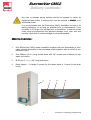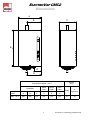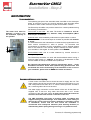
1
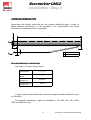
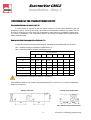
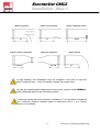
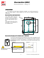
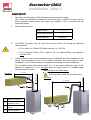
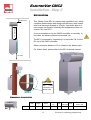
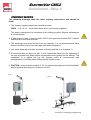
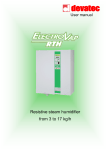
Technical manual Electrode steam humidifier for applications requiring from 1 to 4 kg/h 1 Pictures for illustating purposes only 2 Pictures for illustating purposes only ELECTROVAP CMC2 Contents Safety information Product accreditation RoHS declaration Delivery contents Dimensions & weight Humidifier component parts 4-5 6 7 8 9 10 Installation Step 1 - Unit wall installation Step 2 - Water connection Step 3 - Steam distribution pipes Step 4 - Condensate draining Step 5 - Electrical connection Step 6 - Control signal wiriing 11-12 13 14 to 20 21 22 to 27 28 Cylinder maintenance Cylinder maintenance guide Check list 29 30 Maintenance Cylinder cleaning Valve maintenance 31 32-33 3 Pictures for illustating purposes only ELECTROVAP CMC2 Safety information IMPORTANT Please read, heed and follow the enclosed safety information and the warning labels inside the humidifier before installation or maintenance. Warnings & safety symbols Warning : This symbol is used to designate a danger of injury or potential damage to the system. Caution : High voltages are present inside the humidifier. All works concerned with the electrical installation must be carried out by skilled and qualified personnel. Caution : Danger of scalding ! The ElectroVap CMC2 generates steam during operation and therefore surfaces and pipe-work become very hot. Ensure that equipment not sustaining high temperatures be kept away. Warning : the end user should ensure that the equipment be disposed of according to the local prevailing regulations. Delivery and storage Any loss or damage during delivery should be reported to carrier by registered letter within 3 working days and be advised to devatec or to authorized dealer. It is recommended that the ElectroVap CMC2 humidifier be kept in its transit packaging for as long as possible prior to maintenance. If the humidifier is to be put into storage prior to installation, it must be stored under cover and protected from physical damage, dust, frost, rain and humidity. More than 6 months storage is not recommended. 4 Pictures for illustating purposes only ELECTROVAP CMC2 Safety information GENERAL This manual contains all details necessary for the planning and installation of the ElectroVap CMC2 humidifier. In addition commissioning and maintenance details are included. The manual is intended for use by engineers and properly trained technical personnel. Maintenance, servicing or repair work must only be carried out by suitable skilled and qualified personnel, the customer must be responsible for ensuring their suitability. Any risks or hazards, especially when working from ladders or towers should be identified by a skilled and Health and Safety representative and effective control measure put in place. No liability will attach to the Distributor if any damage, injury or accident is attributable to inattentive, inappropriate, negligent or incorrect operation of the machinery whether or not caused deliberately. Always isolate all electrical and water supplies before commencing any maintenance. Every effort has been made to ensure details contained in this manual are correct, however, in view of the wide range of conditions experienced in air handling systems, the information provided should only be used as a guide. Please contact your Agent if any doubt. Correct use ElectroVap CMC2 humidifiers are ONLY intended for use with air handling systems or direct air humidification. ANY OTHER APPLICATION IS NOT CONSIDERED USE FOR THE INTENDED PURPOSE. THE MANUFACTURER CANNOT BE MADE LIABLE FOR ANY DAMAGE RESULTING FROM INCORRECT USE. Water ElectroVap CMC humidifiers are designed to be used with mains, demineralized R/O (minimum 30 µ) or softened water. On no account attempt to introduce any other fluid or chemical into the system. Water supply should not exceed 6.0 bar (87 psi) and installation should comply with local regulations. In case the water pressure exceeds 6.0 bar, a water regulator valve must be installed. Electricity All work concerned with electrical installation MUST only be performed by skilled and qualified technical personnel (eg electrician or technicians with appropriate training). The customer MUST be responsible for ensuring their suitability. It is the duty of the installer to ensure that suitable sized cables and MCB protection is provided. Please observe the local regulations concerning the provision of electrical installations. Warranty A two year warranty term—cost and labor—is applicable to the parts of the ElectroVap CMC2 to the exception of the consumable parts (valves, cylinders or parts of cylinders) provided our recommendations of use & maintenance have been adhered to. Failure to specify and fit original parts and accessories will invalidate our warranty. NOTE The manufacturer’s policy is one of continuous research and development. He therefore reserves the right to amend without notice the specifications given in this document. The photographs are for illustrating purposes only. 5 Pictures for illustating purposes only ELECTROVAP CMC2 Product accreditation APPLIED DIRECTIVES Electromagnetic Compatibility Directive : Low Voltage Directive : Machinery Directive : 89/336/EEC, 2004/108/EC 73/23/EEC, 2006/95/EC 98/37/EC Amending Directive 89/392/EEC Standard(s) to which Conformity is declared : EN 61000-6-3 : Electromagnetic compatibility generic requirements (residential, commercial and light industries) EN 55022 class B conducted and radiated emission limits) EN 61000-6-2 : Electromagnetic compatibility (EMC) – Generic standards –Immunity for industrial environments; EN 61000-4-3 : Radiated, radio frequency, electromagnetic field immunity test. EN 61000-4-6 : Immunity to conducted disturbances induced by radio frequency fields EN 61000-4-4 : Electrical fast transient/burnt immunity test EN 61000-4-5 : Surge immunity test EN 61000-4-2 : Electrostatic discharge immunity test EN 60204-1 : Safety of machinery – Electrical Equipment of machines – Part 1 : General requirements EN 292 Parts 1 & 2 : Safety of machinery basic principle mechanical design. Manufacturer’s Name and Address DEVATEC SAS Rue Saint Eloi 76550 Ambrumesnil - FRANCE Authorised Representative Type of equipment ELECTROVAP CMC Model Name (s) & Series: ELMC / CMC2 Year of Manufacture 2007 We the undersigned, hereby declare that the equipment specified above conforms to the above Directive(s) and Standard(s). Mr FRAMBOT Jean-François Managing Director Date : 02.07.2008 6 Pictures for illustating purposes only ELECTROVAP MC2 RoHS declaration devatec sas Rue Feu St Eloi 76550 Ambrumesnil France Confirms that the ElectroVap CMC steam humidifier is manufactured in compliance with the European regulations 2002/95/EU (RoHS). This guideline regulates after July 1st 2006 the use of mercury, cadmium, lead (soldering processes), chrome VI as well as PBB and PBDE. ELMC steam humidifiers manufactured previously to this date may contain above materials. Name : MINFRAY Jean-Marie Position : R&D Engineer Date : 05.06.2008 Signature: 7 Pictures for illustating purposes only ELECTROVAP CMC2 Delivery contents Any loss or damage during delivery should be reported to carrier by registered letter within 3 working days and be advised to devatec or to authorized dealer. It is recommended that the ElectroVap CMC2 humidifier be kept in its transit packaging for as long as possible prior to maintenance. If the humidifier is to be put into storage prior to installation, it must be stored under cover and protected from physical damage, dust, frost, rain and humidity. More than 6 months storage is not recommended. What is in the box : 1. One ElectroVap CMC2 steam humidifier supplied with one disposable or cleanable cylinder according to the purchased model together with an on/off or proportional control. 2. One 500mm (20 in.) long flexible hose with 3/4” thread (with washers) for tap water connection. 3. Ø 25 mm (1’’) 1 m. (39’’) long drain hose : 4. Hose clamps : 3 clamps (2 pieces for the steam hose & 1 piece for the drain hose) 1 8 3 2 4 Pictures for illustating purposes only ELECTROVAP CMC2 Dimensions A1 E1 C1 1 B D 1 G 1 Weight ( Kg ) Overall dimensions ( mm ) Humidifier Model CMC 1 to 4 Water inlet Steam outlet Drain outlet A B C D E G 550 490 272 215 140 140 9 Empty In operation 25 35 Pictures for illustating purposes only ELECTROVAP CMC2 Humidifier component parts 1 14 2 13 3 12 4 5 11 6 10 7 8 9 1 Steam hose 2 Power electrode wire 3 Steam production cylinder 4 Stainless steel electrode plate 5 Cylinder strainer 6 Drain valve 7 Drain cup 8 Water inlet valve 9 Stand-by light 10 On / Off rock switch 11 Power contactor 12 Remote information board (option) 13 Main circuit board 14 Filling cup 10 Pictures for illustating purposes only ELECTROVAP CMC2 Installation - Step 1 Unit wall installation TAKE CARE : The humidifier should be installed in a room the temperature of which must be between 5°C and 40°C that the humidity level should not exceed 80 %. The rear part of the CMC2 becomes hot during operation (about 60°C). Make sure that the surface on which the humidifier is installed can sustain hot temperatures. The devatec steam humidifiers are designed to be installed on wall. Make sure that the surface the humidifer is hanged on is strong enough. Install the humidifier at the shortest distance of the steam pipe (s.a. page 19) whenever possible for best performance. 500 mmmini Arrange position of the humidifier on wall to provide free access for easy maintenance (see after installation drawings here under). 600 mm 1250 mm 1000 mmmini 600 mmmini 11 Pictures for illustating purposes only ELECTROVAP CMC2 Installation - Step 1 Installation on wall Nota : Use installation equipment and material appropriate to the surface on which the unit should be hanged . The dimensions mentioned underneath are for cabinets without doors. Method: Mark and drill the mounting holes for 6 mm screws (s.a. the drilling distance table) : CMC2 1-2-3-4 : 4 mounting screws Insert pegs in holes and the upper screws. Allow about 10 mm for hanging the cabinet. Hang the cabinet and level it vertically and horizontally. Screw up the upper screws and then screw up the lower screws. A 1 A 21 1 C1 B 391 DE TAILofA Detail D hanging hole 2x O G 252,5 6 1 R6 20 10 R4 E 1F Dimensions in mm Model A B C D E F G CMC2 1 to 4 17 60 257 390 40 17 257 12 Pictures for illustating purposes only ELECTROVAP CMC2 Installation - Step 2 WATER CONNECTION Recommendations : The operating principle of the electrode steam humidifier is the electrolyse where an electrical current runs through stainless steel electrode plates immersed in water made conductive by the mineral salts it contains. The water level must be between « a » and « b » for the maximum capacity of the cylinder. b a The ElectroVap humidifier can produce steam from 3 water qualities having the following characteristics : Town water or raw water : the water TH should be between 0 and 40° French grade for a conductivity between 1000µ and 350µS/cm (Micro Siemens per centimetre). Softened water: water treated by sodium/calcium permutation on resins. The titration value TH should be kept as constant as possible and between 0° and 2°. It is essential that the salt maintenance of softeners be programmed for the water volume consummed in order to prevent an excessive salt concentration to humidifer once the regeneration cycle is finished (please refer to the softener’s user manual). Duplex softeners are best suited to your humidifier in this regard. In doubt, please consult devatec. Demineralised water: this is a water treatment by reverse osmosis or running through resins. The ElectroVap humidifier can work with demineralised waters having a minimum water quality of 30µS/cm. A tea spoon of bicarbonate of soda must be added on start-up to initiate steam production. No chemical agent whatsoever (chlorine, disinfectant, ozone… ) must be added to the water. Some water qualities may generate foam that can disturb the correct functionning of the humidifier. If this occurs to your humidifier, please refer to devatec for further assistance. Recommendations on water tapping : A fresh mains cold water service should be used to supply the unit. The water pressure should not exceed 6 bar and should not be inferior to 1 bar with a temperature less than 40°C. In case the water pressure exceeds 6 bar, a water regulator valve must be used. The water supply connection is on the bottom of the unit. All the CMC are supplied with a 500 mm long water inlet hose with a 3/4” female connection to the cold water supply. A check valve should be located on the mains and cold water service connection to the unit. The CMC humidifier uses water to produce steam so leakage may happen causing potential damage. If an installation in false ceiling or above prime rooms such as museum, exhibition or laboratory rooms is considered, ensure that the floor below the humidifier is constructed from waterproof materials (with draining facilities) to withstand any water spilling during servicing or if a problem occurs. 13 Pictures for illustating purposes only ELECTROVAP CMC2 Installation - Step 3 STEAM DISTRIBUTION PIPE O25 OU 40 Steam from the cylinder enters the duct via a steam distribution pipe. In order to obtain optimum performance of the humidifier, it is recommended that these instructions be adhered to as far as possible. L 590 1 50 8 2 2 2 1 Steam inlet 2 Condensate drain Steam distribution pipe selection table Steam pipe for the CMC2 steam humidifier : CMC2 Model Number of steam pipe(s) 1-2-3-4 1 Steam inlet diameter (1) Ø 25mm Condensate drain diameter (2) Ø 8mm To get the best steam distribution, select the longest possible distribution pipe to fit the duct. The standard distribution pipes are available in 110, 290, 590, 790, 1000, 1250 and 1500 mm long. 14 Pictures for illustating purposes only ELECTROVAP CMC2 Installation - Step 3 POSITIONING OF THE STEAM DISTRIBUTI0N PIPE Evaporation distance or vapor trail « D » A certain length is required so that the steam coming out of the steam distribution pipe be absorbed by the air. All along this length, descrided as the evaporation distance, the steam can still be seen in the airflow as a mist which can condensate in water against any obstacle if placed within. To prevent condensation, this evaporation distance should be calculated before positioning the steam distribution pipe. How to calculate the evaporation distance « D » In order to determine the evaporation distance, the attached calculation table can be used : HR1 = relative humidity of air before humidification in %. HR2 = relative humidity of air after humidification in %. % RH1 inlet air 5 % HR2 outlet air 10 20 30 40 50 60 70 Minimum humidification distance « D » in m. 40 0.9 0.8 0.7 0.5 - - - - 50 1.1 1 0.9 0.8 0.5 - - - 60 1.4 1.3 1.2 1 0.8 0.5 - - 70 1.8 1.7 1.5 1.4 1.2 1 0.7 - 80 2.3 2.2 2.1 1.9 1.7 1.5 1.2 0.8 90 3.5 3.4 3.2 2.9 2.7 2.4 2.1 1.7 D mini = minimum humidification distance in meters (m). This calculation table is to be used for temperatures between 10 and 25 °C. For lower temperatures, please consult factory. Before / after fan D before / after heater/filter 1.5 x D D 5cm 2,5 x D before thin particule filter 15 Pictures for illustating purposes only ELECTROVAP CMC2 Installation - Step 3 Before a junction D Before / after a constriction before an air opening before a humidity sensor D 5xD before an expansion 0,5 x D 0,5 x D before a bend D A high humidity limit humidistat must be installed in the duct to stop the humidifier in case the leve level of humidity exceeds the preset value. In case the recommended distances cannot be met, please contact devatec or their authorized agent for an alternative solution. If accurate values cannot be reached, a distance of 2 m. should be considered as a minimum distance between pipes & obstruction and 3 / 4 m. before sensor or humidistat. 16 Pictures for illustating purposes only ELECTROVAP CMC2 Installation - Step 3 STEAM DISTRIBUTION PIPE POSITIONING Please meet the following dimensions and spaces according to your configuration. For further information, please contact devatec or their authorized agent. H1 = 110mm = Minimum height between the duct floor and the axle of the steam pipe. H2 = 140mm = Minimum distance between two pipes. H3 = 160mm = Minimum height between the duct top and the axle of the steam pipe. The H3 distance can be 80 mm at the shortest in case the steam pipe is installed at an angle of 30°. 45 ° H > 270 mm The arrow shows the direction of the air flow. ° 1 30 ° à 30 H3 1 H3 8,51 H1 In duct with limited height, the distribution pipe (s) can be tilted by 30° to get the 80 mm minimum height. 15° 590 d 47,2 d/2 In vertical ducts where the air flow is upward or downward, the steam distribution pipe(s) must be tilted by 15° sideways. 17 d = Duct diameter Pictures for illustating purposes only ELECTROVAP CMC2 Installation - Step 3 INSTALLATION For ensuring the best steam distribution possible, we would recommend to install the steam pipes in either diameter as per the two methods described underneath. How to install on a duct (particular) O 84 5 8 8 90 140 36 4X 124 Your steam pipes must be screwed onto the ventilation duct by the fixing plate with a set of 4 bolts and nuts of Ø 5 mm. The length of the bolts will be according to the thickness of the ventilation duct. 100 O 5 How to attach the pipe end ( inside the duct ) - Particular The end of the steam pipe should be attached to the duct with a threaded rod of Ø 5 mm going from the dedicated hole of the fixing plate to the outside of the duct and attached by a couple of nuts (method 1). A rail attached to the inner side of the duct can also be used - a 5mm bolt and nut are used to settle the pipe on the rail (method 2). Method 1 Method 2 Rail The steam pipe must be at level with the duct. Threaded rod 18 Pictures for illustating purposes only ELECTROVAP CMC2 Installation - Step 3 STEAM OUTPUT 1. We would recommend to use the steam hose from devatec supply . NB : when the humidifier is started up for the first time, a smell of burning may be smelt especially when brand new hoses are installed. This is normal and will eventually dispel. 2. Steam hose selection : Model CMC2 1-2-3-4 Nb of steam outlets 1 Steam outlet Ø 3. Ø 25mm The ELMC humidifier can be used with pressure ducts (P) having the following characteristics : If P is inferior to 150mm CE (Water column) i.e. 1470 Pa. If P is between 150mm CE et 300mm CE, our optional filling cup plateform must be used. 4. Please adhere to the recommendations given underneath for the installation of the steam hose according to one of the shown examples, the most suited to your installation. A set of hose clamps are supplied for ensuring a correct installation. The humidifier should be located within 3 m. of the steam distribution pipe. If the distance is superior to 3 m., insulated steel or copper pipe of a slightly larger diameter must be used. Radius of bend for steam hose : 3 m maxi 2 1 Steam hose Ø25mm 2 Obstacle between steam humidifier & pipe 3 Condensate hose Ø8mm to drain 4 Drain tee Ø25mm - Ø 25 mm hose = 250 mm minimal radius Exemple b 3 m maxi 1 1 2 19 3 4 Pictures for illustating purposes only 500 mm mini i min ° 0 1 500 mm mini Exemple a ELECTROVAP CMC2 Installation - Step 3 Wall installation 0,50m mini 3 mètres maxi This Blower Pack BP1 is a steam room ventilation unit which combines performance with design and efficiency with limited size for a maximum flowrate of 15 kg/h. It performs best in a room where the Relative Humidity and temperature does not exceed 75% and 60°C. It can be installed on top the CMC2 humidifier or remotely. In this case, the distance should not exceed 3 m. The BP1 is powered by connecting it to terminals 3 & 4 of the Din rail of the CMC humidifier. Allow a minimum distance of 3 m. ahead of the blower pack. For further detail, please refer to the BP1 technical manual. 1m mini A TAKE CARE : Attach hose on wall before connecting it to Blower Pack DETAILA Dimensions & characteristics BP1 Width Heigth Depth Weight Kg dB Output max Kg/h m3/h Ø steam connecting hose in mm 260mm 170mm 285mm 2 40 15 160 Ø 25 BP1 20 Pictures for illustating purposes only ELECTROVAP CMC2 Installation - Step 4 CONDENSATE DRAINING The following drawings show the water draining connections that should be made. 1. The devatec supplied steam hose should be used : CMC2 1 - 2 - 3 - 4 : 1m Ø 25mm hose with 1 hose clamp (supplied). This hose is designed to be connected to the draining system. Regular replacement is recommended. 2. If rigid piping is used, it must be heat (100°C) and pressure resistant PVC material and have a 60 mm wide diameter. 3. The discharge hose must be free from any obstacle. It is recommended that each steam humidifier has its own drain pipe and tank arrangement. 4. Use water tanks with a lid that has water collecting facilities (s.a. drawings 1). 5. A funnel can also be used (s.a. pict. 2), but it should be offset from the underside of the unit to prevent any steam and/or condensation from getting into the cabinet. The installation of a siphon (as per the draining hose) is recommended and arrangements for holding water spilling should also be made. 6. CAUTION : keep a minimum pitch of 10° for both the draining hose of the humidifier and for general drain pipe (s.a. pictures 1 and 2). Pict. 1 ° 10 10° Pict. 2 10 ° O 60mm mini O60mm mini 21 Pictures for illustating purposes only ELECTROVAP CMC2 Installation - Step 5 RECOMMENDATION : All works concerned with the electrical installation must be carried out by skilled and qualified personnel (eg electrician with appropriate training). The customer is responsible for ensuring their suitability. Please observe local regulations concerning the provision of electrical installations. Check all electrical terminal screws at commissioning, after 50 hours operation and at every service thereafter. Take care : the CMC2 electronic components are very sensitive to electrostatic shocks. Appropriate steps must be taken before any operation. 22 Pictures for illustating purposes only ELECTROVAP CMC2 Installation - Step 5 Electrical table Steam humidifier CMC2 in 2 X 220V - 50/60 Hz In Model Production(KG/St) 1 Imaxi Pmaxi Steam Steam cylinder (A) (A) ( KW ) outlet 1,00 3,3 3,3 0,75 Small Ø 25 mm 2 2,00 6,5 6,5 1,50 Small Ø 25 mm 3 3,00 9,8 9,8 2,30 Small Ø 25 mm 4 4,00 13,11 13,11 3,00 Small Ø 25 mm ALL WORKS CONCERNED WITH ELECTRICAL INSTALLATION MUST BE CARRIED OUT BY A SKILLED AND QUALIFIED PERSONNEL 23 Pictures for illustating purposes only ELECTROVAP CMC2 Installation - Step 5 ELECTRICAL CONNECTIONS All works concerned with electrical installation must be carried out by a skilled and qualified personnel. Make sure that all incoming power supplies are isolated before installation and maintenance of the ElectroVap CMC2 humidifier. 1 3 2 A) 1 - Power supply isolator and MCB 2 - Power supply cable 3– Electrical compartment WARNING : Failure to fit an electrical power isolator and MCB as part of the electrical installation significantly increases the risk of electric shock, which can be fatal. U= 2 x 220-230V CMC2 Q2: 2 poles L1 U(V) 50-60Hz L2 220-230V 50-60Hz N L3 L Q1: 2 poles 2A PE Q1 & Q2: Electrical insulation and circuit breaker Nota: please refer pages 20 & 28 for connecting either a Blower Pack BP1 or a humidistat (options). Failure to observe manufacturer’s installation recommendations will invalidate the manufacturer’s warranty. ALL WORKS CONCERNED WITH ELECTRICAL INSTALLATION MUST BE CARRIED OUT BY A SKILLED AND QUALIFIED PERSONNEL 24 Pictures for illustating purposes only ELECTROVAP CMC2 Installation - Step 5 Wiring scheme : CMC 1 & 2 (2x230V) ELECTRICAL CONNECTION / RACCORDEMENT ELECTR. White (Blanc) CMC Black (Noir) Brown (Marron) 5 4 3 4 2 1 2 0 3 2 X9 1 0 X8 L1 230Vac Enh 5 4 X10 L2 L Ep1 25 24 25 24 Ep2 N Brown (Marron) X6 G 18 X5 19 20 CYLINDER (Chaudiére) 1 % H2O X14 A1 2 DEVATEC Réf:500102 3 29 4 3 28 27 1 White (Blanc) 11 12 11 F1: 2A 26 31 30 10 Connector / Connecteur X05 (19 - 20) 19 20 11 A2 1 L1 3 L2 2 T1 4 T2 Rail DIN L=50mm 5 L3 13 no K1 6 T3 14 no X2 A2 X18 ELECTRICAL CONNECTION / RACCORDEMENT ELECTR. 31 CMC Outlet valve (Vanne de sortie d'eau) F4: 100mA Inlet valve (Vanne d'entrée d'eau) 30 6 7 8 15 9 10 X1 X12 6 8 8 9 10 L1 230Vac 29 L2 L Plug / Prise / 230Vac THR Drain pushbutton (Bouton vidange manuel) L1 28 L2 N 27 G 1 L 26 33 G Power light (Lampe sous tension) 4 1 32 2 devatec WIRING DIAGRAM / Schéma de câblage des CMC1 et CMC2 avec THR DEVATEC Rue Feu St Eloi Tension - Entre L et N = 208V à 240V Made by: JMM VERSION: 04 76.550 Ambrumesnil - France File: CBL_CMC 1_2_THR CE Date Création: 06-03-07 Modifie le: 21/02/14 Mark Intensity 0 6 N SHUNT 1 & 2 3 32 9 Switch On Off (Bouton Marche Arrêt) 2 Brown (Marron) 33 3 16 24 25 Door / porte Divider / Entretoise Cabinet bottom / Fond appareil 5 16 4 Diam cable: 4 mm² 15 Diam cable: 0.75 mm² Fuse function F1 2A Protection of the power contactor coil F2 2A Protection of the inlet valve coil F3 2A Protection of the drain valve coil F4 100mA Protection of the electronic boards ALL WORKS CONCERNED WITH ELECTRICAL INSTALLATION MUST BE CARRIED OUT BY A SKILLED AND QUALIFIED PERSONNEL. 25 Pictures for illustating purposes only ELECTROVAP CMC2 Installation - Step 5 Wiring scheme : CMC 3 & 4 (2x230V) ELECTRICAL CONNECTION / RACCORDEMENT ELECTR. White (Blanc) CMC Black (Noir) Brown (Marron) 5 4 3 4 2 1 2 0 3 2 X9 1 0 X8 L1 230Vac Enh 5 4 X10 L2 L Ep1 Ep2 X6 N 25 24 25 24 Brown (Marron) G 18 X5 19 20 CYLINDER (Chaudiére) 1 % HO X14 31 30 10 Connector / Connecteur X05 (19 - 20) 19 20 A1 11 A2 2 2 DEVATEC Réf:5001002 3 29 4 3 28 27 1 White (Blanc) 11 12 11 F1: 2A 26 1 L1 3 L2 2 T1 4 T2 Rail DIN L=50mm 5 L3 13 no K1 6 T3 14 no X2 A2 X18 ELECTRICAL CONNECTION / RACCORDEMENT ELECTR. 31 CMC Outlet valve (Vanne de sortie d'eau) F4: 100mA Inlet valve (Vanne d'entrée d'eau) 30 6 7 8 15 9 10 X1 X12 6 8 8 9 10 L1 230Vac 29 L2 Plug / Prise / 230Vac Drain pushbutton (Bouton vidange manuel) L THR L1 28 L2 N 27 1 L 26 N 33 G Power light (Lampe sous tension) 3 4 1 32 2 devatec WIRING DIAGRAM / Schéma de câblage des CMC3 et CMC4 avec THR DEVATEC Rue Feu St Eloi Tension - Entre L et N = 208V à 240V Made by: JMM VERSION: 04 76.550 Ambrumesnil - France File: CBL_CMC 3_4_THR CE Date Création: 06-03-07 Modifie le: 21/02/14 Mark Intensity 0 6 SHUNT 1 & 2 2 32 9 Switch On Off (Bouton Marche Arrêt) G Brown (Marron) 33 3 16 24 25 Door / porte Divider / Entretoise Cabinet bottom / Fond appareil 5 16 4 Diam cable: 4 mm² 15 Diam cable: 0.75 mm² Fuse function F1 2A Protection of the power contactor coil F2 2A Protection of the inlet valve coil F3 2A Protection of the drain valve coil F4 100mA Protection of the electronic boards ALL WORKS CONCERNED WITH ELECTRICAL INSTALLATION MUST BE CARRIED OUT BY A SKILLED AND QUALIFIED PERSONNEL. 26 Pictures for illustating purposes only ELECTROVAP MC2 Installation - Step 5 The wiring of the optional equipment described under must be made with 0.75 mm2 flexible cable. REMOTE INFORMATION BOARD (OPTION) Contact can be modified in NO or NF by wiring as per the following schemes (ex: wiring on 30 & 31 = NO contact). NO NF 30 31 32 NO 33 34 35 NF NO NF 36 37 38 X22 connector (36-37-38): Remote steam production dry contact. X21 connector (33-34-35): Non-operational dry contact X20 connector (30-31-32): Remote cylinder maintenance dry contact ALL WORKS CONCERNED WITH ELECTRICAL INSTALLATION MUST BE CARRIED OUT BY A SKILLED AND QUALIFIED PERSONNEL 27 Pictures for illustating purposes only ELECTROVAP MC2 Installation - Step 5 The wiring of the optional equipment described under must be made with 0.75 mm2 flexible cable. Outside connections ON / OFF Electrical compartment % H2O 1 2 Connection with ON/OFF control humidistat, high level safety humidistat or to a ventilation system S1 Dip Switch : Allows to select the kind of regulation (see attached scheme for configu- PROPORTIONAL CONTROL Hygrometer + - 1-2 connection control humidistat high level safety humidistat, or (and) ventilation enslavement 1 % H2O 2 X5 connector : 18-19-20 X5 S1 on 1 2 3 4 0 _ 10 V 2 _ 10 V CMC S1 on 19 19 20 20 S1 on S1 on 1 2 3 4 1 2 3 4 1 2 3 4 4 _ 20 mA 0 _ 20 V 4 _ 20 V 1_5V 28 Pictures for illustating purposes only ALL WORKS CONCERNED WITH ELECTRICAL INSTALLATION MUST BE CARRIED OUT BY A SKILLED AND QUALIFIED PERSONNEL ELECTROVAP CMC2 Cylinder maintenance guide for tap or hard waters Estimated cylinder maintenance curve X= Humidifier steam demand 300 H 800 H 1000 H 2000 H 4000 H Working hours Example given: it is recommended to maintain (if cleanable type) or change (if disposable type) the steam cylinder every 800 to 900 hours of operation for a humidifier running at full capacity and using a water of TH20. The water tightness is indicated in French grade, the said value is the water hydrotimetric content (TH). The water quality is to be mentioned on your request so that to fit the most appropriate steam cylinder for the best working of the humidifier. Length of the genuine stainless steel electrode plates Model CMC2 1 - 2 - 3 - 4 Length (mm) 160 During cylinder maintenance (page n°31), it is recommended to measure the length of the electrode plates. The latter should be replaced when the lenght is shorter than 1/3 or 1/2 of the original lenght (s.a. above table). 29 Pictures for illustating purposes only ELECTROVAP CMC2 Maintenance - Check points ROUTINE SERVICE After the humidifier has run for about one hour time, check for any water leakage at the cylinder gasket and at the drain valve. The cylinder should be inspected after about 50 hours of run. Make sure there is no arcing nor sparkling between the electrodes when the unit is in operation. As well, when switched off, all the contactor screws and the steam, drain and internal hose clamps should be retightened. A complete inspection of all the humidifer hoses should be made after one year of operation. Any faulty or damaged hose must be replaced to prevent leakage. WARNINGS When the humidifier is used for a long time or operates with a very conductive water, solid deposits built-up on the electrode plates which can make the water even more conductive. If electrical arcs can be seen inside the steam cylinder, the humidifier doesn’t operate properly. Switch off the humidifier immediately. This arcing involves : Excessive heat on the plastic shells that can eventually make the material melt and make a hole from where scalding water can escape. Circuit breaking caused by excessive intensity. Faster corrosion of the electrode plates. Burning of the electrode power cables. Points to check in case of arcing If the humidifier works with softened water, ensure that the softener does not supply salt water to the humidifier. Ensure that the drain valve works properly and clean it up (see after page n° 32 ). Ensure that the F3 drain valve fuse is still in order (ref : 500102/10). CAUTION Always isolate all electrical and water supplies to the humidifier before commencing any maintenance and refer to the instructions given in this manual. The CMC humidifier includes live electrical components and the steam cylinder contains boiling water. All maintenance must only be carried out by skilled and qualified personnel. 30 Pictures for illustating purposes only ELECTROVAP CMC2 Maintenance - Cleaning of steam cylinder The CMC2 humidifiers are currently fitted with disposable cylinder. The latter can however be easily substitued for cleanable type at customer’s choice. REPLACING THE STEAM CYLINDER 2. Drain the steam cylinder fully using the manual drain key. When the cylinder is drained fully. Isolate the power both at the general switchboard and at the humidifier (rocker power switch). The steam cylinder may be very hot. Allow it/ to cool down before removing. 3. 4. Remove the front panel from the humidifer to access the cylinder compartment. Remove power and high water level electrode cables from top of the cylinder (picture 1). Disconnect the steam hose(s) from the top of the cylinder (pict. 2). Lift the cylinder upwards until it is clear off the drain valve. Ensure that the gasket remains in the drain valve (picture 3). Release the top of the cylinder from the retaining clip and pull out the cylinder (picture 4). The disposable cylinder will be merely replaced by a new one either disposable or cleanable. Retighten gently the steam hose on the cylinder outlet when the cylinder has cooled down only to prevent deformation. 5. CLEANING THE CLEANABLE STEAM CYLINDER This method is intended for use with the cleanable cylinder only. Mark the edge of the cylinder halves so that they can be matched up when reassembled (picture 5). Remove the maintaining nuts and bolts, split the cylinder halves and remove the gasket and the strainer that must be cleaned (pict 6). Scrap mineral deposits off the electrode plates and the shells (a weak descaling solution can also be used) (pictures 7, 8 & 9). Rince the electrodes, the cylinder shells and the divider. It is important that the strainer at the cylinder bottom be also cleaned. Take care : never chock the shell rims to get rid of the deposits 6. 7. Relocate the strainer into the cylinder bottom. Replace the cylinder gasket, and fit it inside the groove of the lower shell and attach the upper shell with the electrodes . When re-assembling, take care to align both shells. Refit the bolts and nuts. Retigthen them gently (when the cylinder is still cold). Rinse the drain valve ‘o’ ring and grease it or replace it if needed. 8. Important At this stage, the drain valve must be maintained. NB : Refit the cylinder to the humidifier once the drain valve is maintained. 31 9. Pictures for illustating purposes only ELECTROVAP MC2 Maintenance - Valves DRAIN VALVE MAINTENANCE The drain valve should be maintained whenever the steam cylinder is maintained or changed. Once the steam cylinder has been pulled out (please refer to the « cleaning of the steam cylinder » page ), disconnect the drain valve supply wires. Unscrew the solenoid retaining nut and remove the washer. Put them on the cylinder compartment tray. Remove the coil from the valve stem. Unscrew and remove the valve stem and the filling hose from the valve body. Important : Apply some soap on the O-ring and the cylinder draining outlet Remove the « O » ring and the drain valve collar. Remove any pieces of calcius, rinse the steam and the body with fresh water. Assemble in reverse order. It is now time to locate the new or cleaned steam cylinder in its compartment in proceeding this way : set the maintaining clip on the steam cylinder outlet, engage the drain outlet into the drain valve and push the cylinder downward. Reconnect the power cables. Make sure that the power cable with the brown identification mark be connected to the cylinder connection identified with a brown spot. If the brown spot is missing, the cylinder electrode connection can be identified as the one closest to the high water level probe. Locate the steam hose and fasten the clamp. Ensure that all the clamps are properly tightened whenever the humidifier is maintained. 32 Pictures for illustating purposes only ELECTROVAP CMC2 Maintenance - Valves INLET VALVE MAINTENANCE The inlet valve should be maintained every 6 months as a minimum and after 50 hours operation. 1 Isolate the water supply and remove the water supply hose from the valve. Disconnect the electrical wires from the coil. Untighten the collar clamp and remove the water feed hose. Unscrew the black nut 1 and lay it on the cylinder compartment tray. Take the valve out and remove the basket filter from the base of the valve with a pair of long nose pliers. Pull the coil out with a flat screw driver. Wash the basket filter under clean water to remove any dirt and debris. Replace whole valve if cleaning is not practical or replace coil if necessary. Assemble in reverse order taking care to replace collar clamp if necessary. Ensure that everything is correctly assembled and switch the humidifier on. Ensure that all the clamps are properly tightened whenever the humidifier is maintained. 33 Pictures for illustating purposes only 34 Pictures for illustating purposes only 35 Pictures for illustating purposes only LR 94104-2 87 Rue Feu St Eloi 76550 Ambrumesnil - France Export division: tel. +33 (0)2 35 83 06 44 or +33 (0)2 35 83 03 86 fax. +33 (0)2 35 85 36 72 Email: [email protected] - www.devatec.com devatec reserves the right to change specifications or design of the equipment described in this brochure without prior notice. 36 Pictures for illustating purposes only CMC2 CMS - 21-02-14 edition