1
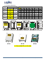
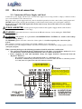
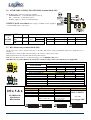
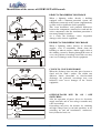
DRM 3~
l
a
b
o
l
G
3
ty
n
a
r
War
Vac stepless controllers
for
YEAR
FAN speed Control Solutions
Three-phase asynchronous Motors of
Axial & Centrifugal Fans
DRM300 series Code Selection
The following table shows how order codes are created and which versions are available for each Characteristic or Function
ZN DRM
α
ββ
χχ
δ
ε
φ
γ
η
ϕ
α
Number of Phases
Nominal current
(RMS at50°c)
Voltage supply
Frequency
Operating
characteristics
Control inputs
configuration
Protection CASE
Options
Revision index
ββ
χχ
δ
ε
φ
γ
3
08
12
18
20
28
40
23
48
0
0
3
Three-phase Power Supply R-S-T + PE
C
Control Signals Standard Configuration:
0-10Vdc & 4-20mA & PWM (3-30V not polarized)
S
G
P
0
4
8
0
For external installation, Protection degree IP 55 / 120°C
η
ϕ
8 Ampere
12 Ampere
18 Ampere
20 Ampere
28 Ampere
400Vac (MIN limit: 380Vac / MAX limit: 440Vac @ +/-10%)
230Vac +/-10%
480Vac (MIN limit: 460Vac / MAX limit: 500Vac @ +/-10%)
50Hz /60Hz with automatic selection of the power supply frequency
Controlled Power Unit
“Step-Starter” Version, for textile ducts (on request)
For internal installation, Protection degree IP20
For internal installation, Protection degree IP00
Standard connection three-phase + Ground
Connection to N° 4 motors (12A/18A/20A models) three-phase + Ground
Connection to N° 8 motors (20A / 28A model) three-phase + Ground
Last SELPRO revision:
the most recent revision of the product will be delivered
The given current values (RMS) are at full load at an environmental temperature of 50°C
IP 55
User Manual DRM300 / rev. 4.1 30.11.09
IP 20
1
IP 00
www.selproweb.com
! WARNING !
Safety warnings
•
•
•
•
•
•
•
•
•
•
•
•
•
•
•
•
•
•
•
•
•
•
•
•
Follow the instructions in this manual exactly and observe all safety measures in force. Always keep the present documentation close to the control
device.
The purchaser must previously ascertain the suitability of the product for the use it is intended for and assume all consequent risks and responsibility.
This product has been designed to be used only as an operational control device. In the event delicate or great value products should be held within
specific working limits, it is recommended to install a separated control device, equipped with alarm contacts.
The commissioning, start-up and operation of the present device must be performed by qualified technicians with knowledge of the technical regulations
in force, in compliance with all the safety standards and able to understand the indications of danger.
The regulator must be installed by qualified personnel who will connect the electric supply, attach the cables in their permanent positions and
commission the plant. Incorrect installation of the DRV300 voltage regulator or the fan connected to it may cause damage to objects or people.
Before supplying power to the unit, make sure that the regulator is correctly connected to the power supply and to earth.
The information provided in the present manual consent to install and control correctly the fan speed regulator DRM300.
Do NOT tamper with or disassemble the regulator internal components; doing so will INVALIDATE THE GUARANTEE and may cause
unnecessary damage.
The regulator does not contain components that can be repaired by the user.
The regulator must be suitably and effectively earthed by the installer according to the standards in force; Earth is essential for the EMC filter to operate
correctly.
The user must be protected from the electric supply and the motor must be protected from possible overloads in compliance with the standards in force.
DO NOT supply the regulator without the external protection cover.
DO NOT touch any electrical parts of the circuit when the power supply is connected under any circumstances.
Before supplying power to the unit, make sure that the regulator is correctly connected to the power supply and to earth;
If the mains supply is "disturbed", which may be due to other electrical power components causing irregularities in the supply (power contactors), it is
recommended that supplementary three phase ‘SURGE ARRESTER’ filters are installed directly on the regulator supply.
Avoid repeatedly connecting and disconnecting the power supply to the regulator; a constant supply keeps the regulator at working temperature and
eliminates problems caused by condensate inside the protection case.
Alternatively, use the remote terminal board contact ‘M3’ S2 = ON/OFF.
The S2 = ON/OFF contact on the terminal card M3 does not cut the mains supply and therefore cannot be used as a safety switch.
Install the regulator out of direct sunlight, in order to protect the case from overheating.
The appliance can operate at environmental temperatures up to 50°C. Do not install it where this temperature may exceed, otherwise the integrity of the
regulator will be compromised, since the controller may make the user appliance operate at full load (100%) with all consequent effects.
The equipment must be placed vertically, in order to encourage heat dissipation and to ensure sufficient air circulation in a free space measuring at least
150 mm above and below the regulator. If several regulators are to be grouped together on a single electric board, please provide forced air circulation
with a fan or with a sufficiently powerful cooling unit.
Use the holes on the lower and power terminal board sides of the appliance, for entrance of the connection cables. This will prevent water, dust etc. from
getting in and will ensure the IP55 protection level is maintained using adequately sized cables and sheaths of suitable quality.
Reassemble and check the cover of the external protection panel is properly closed.
DO NOT alter or damage the identification stickers on the equipment.
i Terms of use
The DRM 300 series devices are designed to vary the three-phase AC voltage thanks to the phase cutting principle, in order to regulate the rotational speed of
three-phase asynchronous high-slip motors, to be used with axial and centrifugal fans in Air-Conditioning, Refrigeration, Ventilation and Air Treatment
Systems.
Any different use of the equipment is strictly FORBIDDEN.
i Manufacturer Declaration
This series is manufactured for the employment into the industrial environments and responds the following communitarian directives:
• Machine Directive 2006/42/EC and following amendments
• Low Voltage Directive (LVD) 2006/95/EC
• EMC Directive 2004/108/EC
(*) ELECTRONIC FANS REGULATION - FULL ENVIRONMENTAL RESPECT
Thanks to the electronic solutions used, the device responds totally to the emission limits required from the European Directives for Residential, Commercial
and Light Industrial environments (EMC and PDS applications), and can therefore be installed without particular precautions ( ex.: shielded cables).
The equipment does NOT contain filters for the suppression of harmonic distortions.
It is not allowed to commission our equipment when installed in machines that do not
comply with the legislation in force.
User Manual DRM300 / rev. 4.1 30.11.09
2
www.selproweb.com
Contents
1.0
2.0
3.0
4.0
5.0
6.0
PRESENTATION ………................................................................................................................................................................................................ 4
1.1
Introduction ……… ....................................................................................................................................................................................... 4
1.2
Operating MODES ......................................................................................................................................................................................... 5
1.3
General functions DRM 300 series ................................................................................................................................................................ 6
1.4
EC Directives & Technical standard ............................................................................................................................................................. 7
1.5
DRM300: Technical characteristics .............................................................................................................................................................. 8
1.6
Mechanical Dimensions ................................................................................................................................................................................ 10
1.7
Electric Motors ............................................................................................................................................................................................ 11
1.8
MagnetotHermAL Protection ...................................................................................................................................................................... 11
ELECTRICAL CONNECTIONS ................................................................................................................................................................................ 12
2.1
Connection of power supply and load ......................................................................................................................................................... 12
2.2
Available options for Multi-FANs connections........................................................................................................................................... 13
2.3
Control signals & auxiliary contacts connections....................................................................................................................................... 14
2.4
DIP-Switch (DSw1- DSw8)........................................................................................................................................................................... 14
2.5
Remote controls signals 0-10Vdc / 4-20mA / PWM (M3) .......................................................................................................................... 15
2.6
Auxiliary Contacts & Signals (M3) ............................................................................................................................................................. 16
2.7
RL1 Alarm relay terminal block (M4) ........................................................................................................................................................ 16
ALARM ………………. ................................................................................................................................................................................................. 17
3.1
Alarm LED DL3 ........................................................................................................................................................................................... 17
FUNCTION DIAGRAM ................................................................................................................................................................................................ 18
4.1
SLAVE power unit - Function diagrams .................................................................................................................................................... 18
ACCESSORIES……… .................................................................................................................................................................................................. 19
5.1
Manual remote control units........................................................................................................................................................................ 19
5.2
pressure transducer for 4-20 mA & 0-5 Vdc............................................................................................................................................... 20
5.3
temperature probe NTC (10 kohm@25°c).................................................................................................................................................. 20
6.3.1
NTC housing .................................................................................................................................................................................. 20
5.4
RGF-MEI-4 / Universale input Expansion Module................................................................................................................................... 20
5.5
Noise (extra-db) suppression FILTER for phase-cutting regulators ........................................................................................................ 21
5.6
Filter for suppression of Harmonic Distortions (IEC 61000-3-2 & 61000-3-12) ...................................................................................... 22
DRM300 - Electrical Tests ............................................................................................................................................................................................. 23
Description of symbols used in the present manual
! Attention !
i
EMC
LVD
Information
Compliance with: CE mark –Electromagnetic Emissions – Low Voltage Directives
PRODUCT end of life – WEEE directive EU 2002/96/EC
User Manual DRM300 / rev. 4.1 30.11.09
3
www.selproweb.com
1.0 Presentation
1.1 Introduction
Fans represent the essential part of Air Handling equipments and systems, and the development of machinery for the variation of speed – and,
consequently, of air flow rate– in the different types of systems has emphasized their importance.
The variation of volumetric flow rate in a system may be required according to several needs:
- NOISE –operation proportional to appropriate speed values according to environmental conditions
- CONVENIENCE – the energy consumption is always in line with the actual ventilation needs
- FUNCTIONALITY – elimination of heavy and bulky electromechanical components and easier electrical assembly
- CONFORMITY – in full respect for European directives about electrical power drive systems
- MECHANICAL WEAR – mechanical stress in structures, due to an ON/OFF operation
- ELECTRICAL WEAR – stress of the electromechanical components and of the connected devices.
In order to fulfill such requirements, it is necessary to use regulation equipment able to adjust the rotational speed of fans, so as to make the
system more suitable for the variations of contextual operating conditions.
There are several types of equipment that allow to control and regulate fans driven by asynchronous motors.
Since a long time the following solutions have been used:
1. ELECTROMECHANICAL equipment for the ON-OFF activation of fans
2. ELECTROMECHANICAL equipment for the ON/OFF + STAR-DELTA activation of fans motors (MIXED mode)
Later, also the following modes have been discovered and used:
3. ELECTRONIC equipment with STEP VOLTAGE control (AUTOTRANSFORMER)
4. ELECTRONIC equipment with FREQUENCY variation (inverter or electronic motor)
5. ELECTRONIC equipment with AC voltage PHASE CUTTING
The activation of an ON-OFF group of fans allows the modulation of the Air System, but the result is very unstable and it never meets the
real requirements of the system.
Only thanks to the electronic equipment it has been possible to obtain a steady balanced Air System. Electronic solutions also bring many
advantages:
Reduction of the operating noise: the dBs are proportional to the fan speed, with a consequent general noise decrease (dB) in the
Air System and the possibility to set a NIGHT operation mode that allows a further reduction of power consumption and meets the
requirements of low noise (dB).
ENERGY saving: thanks to the gradual absorption of power from the mains, it eliminates current peaks due to a frequent ON-OFF
of the group of fans.
Longer electrical and mechanical life of the equipment, which is preserved from thermal and electrical stresses typical of an ONOFF regulation.
Elimination of “fluid hammers”, caused by pressure surge due to the ON-OFF modulation of the heat exchanger.
Constant operating parameters (temperature, pressure, air flow rate, etc…) for the whole Air System, with a sensible increase of
mechanical and electrical lifetime of the components of the system.
Furthermore, the proportional regulation allows to:
Utilize equally the whole surface of the constantly operating heat exchanger;
Manage the heat exchanger’s power in a more rational and balanced way, by operating gradually at low speeds and consequently
optimizing the exchange power through a better use of fins;
Regulate the operating efficiency of the heat exchanger according to the actual cooling needs;
Reduce the total amount of coolant;
Reduce dirt and dust accumulation on the heat exchanger fins;
Make the mechanical structure of the heat exchanger easier, by eliminating the internal partition walls.
Among the different type of equipment that allow to perform a proportional regulation of the rotational speed of fans driven by synchronous
and asynchronous motors, there are also the FAN SPEED CONTROLLERS with AC voltage PHASE CUTTING.
With these controllers, the active voltage given to the motor varies proportionally from a minimum up to a maximum value, which
corresponds to the AC voltage supply; the required frequency is the mains frequency: 50 or 60 Hz.
This kind of regulation requires the use of motors suitable for phase-cutting control (class F or H and defluxed), since they must be able to
stand an increase of the internal temperature at low operating voltages, which may causes a severe deterioration of the motor windings and
even short circuit in NOT suitable motors.
In general, it is suggested to use: motors with resistive, high slipping rotor in silumin, defluxed, tropicalized, CLASS H motors, since
they give better performances in speed variation, are quieter and need lower inrush currents.
When choosing the motor, it is always recommended to contact your equipment supplier and order a motor suitable for voltage variation
(ADJUSTABLE) and perform practical tests of the motors or prototype machines, in order to verify their proper operation.
! WARNING !
Before installing the DRM300 regulator, you are invited to read this manual, which describes the necessary
procedures for correct installation and commissioning of the controller DRM300
User Manual DRM300 / rev. 4.1 30.11.09
4
www.selproweb.com
The digital DRM300 series, dedicated to applications for Air-cooled Heat Exchangers, consist of:
•
•
•
Configurable controller in n° 03 numbers of available SLAVE modes, simply by selecting with DIP-Switch and connecting to the
controls signals terminal block
Two (2) inputs, for the connection and the management of one or two signals through mA – Vdc signals
i
The following regulation functions are also available:
DIRECT-REVERSE operating mode
Start-Stop: contact for remote OFF or Heat-Pump mode, active by closing the contact
T.K.: NO/NC contact for the connection of the thermal motor protection
RL1: GENERAL alarm relay, with programmable Dip-Switch activation modes
•
Analog output 0-10Vdc, used in order to control:
i
-
Up to ten Slave DRIVER POWER UNITS (rS), with control signal 0-10Vdc
Once the desired regulation mode have been selected, the controller is ready to operate and control the fan speed, so as to maintain
the system constantly stable within the preset operating range.
1.2 Operating modes
Phase cutting regulation, totally controlled over the three phases, in order to vary the active voltage applied to the load, no neutral
connection required.
It is possible to use the device in one of the following SLAVE modes:
•
SLAVE POWER UNIT: the VAC output varies according to the Vdc-mA signal received at the input IN1 & IN2, or to the PWM
input, and increases/decreases as the control signal increases.
The number of regulation signals/sensors/transducers can be increased by connecting the control unit to the Universal Input Expansion
Module RGFMEI-4, which allows to connect up to 4 mA – Vdc – NTC sensors/signals to each controller input; it is always possible to
select the signal with Highest/Lowest value as a reference point for the regulation; the controller allows the cascade connection of up to 6
RGFMEI-4 units.
Expansion Modules MEI-4 have been designed to be connected to diverse regulation and control devices, such as inverters or PLC, which
accept a 0-10Vdc or 0-20mA control signal.
WARNING !
Before installing the DRM300 regulator, you are invited to read this manual, which describes the necessary
procedures for correct installation and commissioning of the controller DRM300
User Manual DRM300 / rev. 4.1 30.11.09
5
www.selproweb.com
1.3 General functions - DRM 300 series
The DRM300 series, designed & created by the SELPRO Research & Development Department, has been specifically developed to offer a
digital UNIVERSAL controller for the regulation of three-phase asynchronous motors, with dedicated software for applications on Aircooled Heat Exchangers used in Air Conditioning and Refrigeration Systems.
Such kind of digital regulation optimizes the application-specific performance of ventilation control; it is based on a simple and yet
innovative technology, one hundred percent ITALIAN as it has been conceived and developed in SELPRO labs, and it fully satisfies the
following requirements:
i
SIMPLICITY
USER FRIENDLY
FUNCTIONALITY
COMPLETENESS
PLUG & PLAY
ALL in ONE
SAFETY
CONFORMITY
ALL ROUND PROTECTION
COMPLIANCE
- NO need of special cables for the installation
- NO need of trained operators for the startup procedure
- all regulation parameters are already default preset
- all regulation modes with mA–Vdc–PWM signals are already default
preset,
- the software supervises the operation of regulator and connected fans,
- the system “Controller + Fan/s” is guaranteed for all PDS applications
As a consequence, the digital DRM300 controller is:
-SIMPLE, what concerns electrical connections and programming,
-FLEXIBLE and ready to be used, as it is already preprogrammed for all SLAVE applications,
-COMPLIANT, in conformity to the strictest standards concerning power drive systems, with special attention to the EMC Directive
(Electromagnetic Compatibility): since it refers to NON tangible protection requirements, the relative Standards are only partially followed
by many manufacturers of electronic power devices, and they are ignored especially by final users, which are the contact persons responsible
for the EC certification and compliance of the System “Controller + Fan/s”.
Like all SELPRO products, the DRM300 series has been built to the very highest quality standards using electronic components of the utmost
reliability, which have undergone functional tests that guarantee the use of the product for at least 60,000 hours of continuous operation
without problem.
Thanks to the specialized software for applications on fan motors, it is possible to avoid typical problems with the modulation of oscillation,
to reduce the mains current distortion and to limit the magnetic noise of the regulated motor by means of the Soft-Power technology, which
manages power regulated in 0-cross mode.
The extended range microprocessor, which performs every control function, is also responsible for monitoring the safety conditions of the
regulator by checking its proper operation, the lack of one phase toward the power supply, the connection of sensors and all other possible
electrical situations that could damage the connected air-cooled system or the controller, and by simultaneously informing the operator about
the regulation status and operating conditions through the LEDs.
The controllers are preprogrammed for operation with SLAVE (3 modes) configurations.
The controller in SLAVE mode operates as a power unit, driven by a remote controller, through a mA or Vdc or PWM control signals.
The DRM300 series offers 5 standard rated current values:
i
8 A / 12 A / 18 A / 20 A / 28 A, with standard power supply 400Vac +20/-10% 50/60Hz (the controller recognizes and manages
automatically the frequency variation); further voltage (230 Vac / 500 Vac) and current values are available on request.
Electronic regulations of motors, phase cutting regulation of AC voltage, SCR and TRIAC power drive systems: they all have collateral
effects, which require the use of additional technical protection measures especially with applications in residential environments or
technological plants; the acoustic noise - generated by the fan because of the magnetization of the motor itself – arises discontinuously within
the main speed ranges of the fan speed regulation, and can be only partially reduced by means of expensive and bulky acoustic screens
installed around the machinery.
The DRM300 controller helps solving issues brought about by the acoustic noise thanks to its dedicated software, which allows with the
action of the NTF300 filters – specifically designed for the Extra-dB-Noise applications – it is possible to suppress up to the 80% of noise
emissions, generated by the fan motors.
The fans can therefore operate at the different required speeds without causing the typical noise arising from a phase cutting regulation; the
physical geometry and heat exchange capacity of the finned coil are enhanced by the “clean” regulation obtained, which at the same time
consents to save energy.
Unlike INVERTERS, thanks to the application of NTF300 filters on our devices it is also possible to dramatically lower and almost eliminate
harmonic distortions generated by electronic control.
The regulator does NOT have any internal filter for the suppression of harmonic distortions (EN-61000-3-2 & 3-12).
User Manual DRM300 / rev. 4.1 30.11.09
6
www.selproweb.com
1.4 EC Directives & Technical Standards
Like all of our products, the DRM300 series has obtained the CE mark in compliance with the EMC (Electromagnetic
Compatibility) directive 2004/108/EC.
The essential requirements of the directive are satisfied by the conformity to the “generic standards” for industrial
environments.
i
Directive
2006/42/EC
2006/95/EC
Standard code
EN 60204-1
EN 60204-1
EN 50178
2004/108/EC
EN 61800-3
Description
Safety of machinery. Electrical equipment of machines.
Safety of machinery. Electrical equipment of machines.
Electronic equipment for use in power installations.
Adjustable speed electrical power drive systems. Part 3: EMC
product standard including specific test methods.
All products have been tested in accordance with the procedures and test conditions laid down in the standards specified in the
product technical file.
Since these products are destined to be used not only as “stand alone” systems, but also as components of other machines or
plants, all compatibility tests to the standards have been performed under typical conditions of use.
In particular, the tests have been performed in a system consisting of a voltage controller DRM300, a control cable and relative
commands, a supply cable, a motor cable and a group of fans with an equivalent power to the value of the nominal current of
the controller.
With reference to EMC Compatibility, according to the Marking
EMC
LVD
with
CDM System
with
PDS System
All SELPRO controllers are suitable for the installation in PDS systems (Power Drive System = Controller
with connected fan/s), which guarantee the EMC compliance of the System “Controller + Fan/s”.
The final specifications of the system or plant, in compliance with the EMC directive, are in any case the
responsibility of the installer, who must put the system into operation carefully, according to the rules in
force and following the information provided by the present manual.
i
PRODUCT end of life EU 2002/96/EC
The device must be disposed of separately, according to the local authority advice.
User Manual DRM300 / rev. 4.1 30.11.09
7
www.selproweb.com
1.5 DRM300: Technical Characteristics
Power supply
Operating
principle
Current
420VAC +/- 10 % Three-phase - ( on request 230VAC / 500 VAC)
Voltage
50 / 60 Hz automatic selection
Frequency
For Installation Category II ( 4 KV )
Overvoltage Protection
Electronic three-phase voltage regulators for the phase-cutting regulation (through SCR, total control on the
three phases) of the active voltage applied to the load; compensation for inductive loads and motors.
Rated
Overload
Control circuits
Power
Operating
characteristics
Thermally dissipated
SLAVE CONTROLLERS
rS
Analog control signals
INPUT
Signals &
Contacts
INPUT
Signals &
Contacts
The output voltage varies according to the value of the remote control signal
DIRECT: the output increases as the input increases,
REVERSE: the output decreases as the input increases.
Default: the VAC output increases as the controlled variable increases
The controller can be preset through the keypad on board. Any combination of the
following operating modes is available:
0 – 10 Vdc (*)
4 – 20 mA
Code
Code
Ri = 10 kOhm
Ri = 100 Ohm
rS-010
rS-420
(*) DEFAULT CONFIGURATION
Logic control signal
PWM digital signal, from 3V to 30V, insulated and not polarized.
PWM
3 to 30 V
Code
rS PWM
Start-Stop / Heat-Pump
Programmable free potential “On/Off” contact: with Sw4 (for NO or NC)
T.K. motor
Free potential “On/Off” contact (NC)
Analog control signal
Slave Unit control signal : 0-10 Vdc - max 30mA
Auxiliary Supply
+20V +/- 20% , max 40mA not stabilized, protected from short-circuit
+5V
max 20mA stabilized and protected from short-circuit
Potentiometer supply
+10V / 5mA stabilized & protected, for external manual command
RL1 Relay
Contact COM , NC, NA for Alarm relay RL1
Dip Swicht
Available
functions
selections
08 A up to 50°C environment; if over, decrease 0,6 A/°C
DRM 308
12 A up to 50°C environment; if over, decrease 0,6 A/°C
DRM 312
18 A up to 50°C environment; if over, decrease 0,6 A/°C
DRM 318
20 A up to 50°C environment; if over, decrease 1,0 A/°C
DRM 320
28 A up to 50°C environment; if over, decrease 1,0 A/°C
DRM 328
150% of the rated current (max. 10” every 3’)
Control circuits
5VA
DRM 308
32 W @ 8A
DRM 320
80 W @ 20A
DRM 312
48 W @ 12A
DRM 328
112 W @ 28A
DRM 318
72 W @ 18A
DSw
12345678
User Manual DRM300 / rev. 4.1 30.11.09
DSw
DSw
DSw
DSw
DSw
DSw
DSw
DSw
1
2
3
4
5
6
7
8
Select the regulation 0-10Vdc or 4-20mA for IN1 & IN2
Select the regulation mode: Direct / Reverse
Select the regulation: Linear / Quadratic
Select the NO/NC function mode of the Start-Stop
Select the RL1 alarm mode
Select the RL1 alarm mode
To active the CosPhi adjust
Available for CUSTOMER custom, on request
8
www.selproweb.com
Visualisation
Leds
Predispositions
PWR
DL1
Green
CPU RUN
DL2
Green
Alarm FAIL
DL3
Red
PWR OUT
%PWM IN
RL1
DL4
DL5
DL6
Green
Green
Green
Starter
Cut-Off
Input command
Alarms
Power supply
Working controller
Overvoltage protection
Inputs
Controller
Mains monitoring
Protections
Mains filter EMC (**)
Case
Insulation
Work
environment
Installation
Electrical
Connections
Compliance
Power supply ON
•
Regulation O.K. : blinking DC 50%, freq ½ Hz
•
Regulation CosPhi ON : blinking DC 50%, freq 2 Hz
1 blink
Over max °C control card (85°C)
2 blinks
3 blinks
VAC power supply phase loss
Thermal protection open
Over range signal :
4 blinks
•
Slave 4-20mA : < 2mA ; > 24mA
•
Slave 0-10Vdc : > 11,0Vdc
DRM run: VAC output on work
PWM % on input (M3: 8/9)
RL1 relay (NO = relay ON)
5”
The regulation is setted at the 25% of the VAC power supply
Verify the input signal range :
- 0-10 Vdc > max value under 11Vdc
- 4-20 mAdc > min value 2mA and max value 24mA
Phase loss – Power supply under range (less 20% Vac supply)
Verify the phase-loss, the low VAC limit (max -20%); Alarm ON with Led DL4
(red) & relay RL1 (OFF)
Verify the working °C with internal probe (max 85°C)
Complying with EN 61000-4-5: Overvoltage Category II (4 KV)
With PTC for short-circuits
Internal thermal protection
It checks the simultaneous presence of all the three mains phases; in case of
lack of one phase, or insufficient power supply, the device is stopped and
the situation is displayed by:
Led FAIL=ON and ALARM=OFF + relay RL1=OFF
Suitable for the installation in PDS systems (Power Drive System =
Controller with connected fan/s), for Residential, Commercial and Light
Industry environment
(** ATTENTION! : In presence of a protection with DIFFERENTIAL
system, use switches with leakage current to ground ≥ 60 mA )
Available case
IP55
IP 20
IP 00
Materials
GW-Plast 120°C (max. temperature 120°C) and aluminium
Locking screws
TPN series with max. tightness 2,5 Nm. (according to CEI 23-58)
Protection degree
IP 55
Environmental pollution
High pollution
Fire resistance
D Category
Case
Class I (use of protective earthing conductor)
Control circuits
4000Vac between control input and mains voltage components
Working temperature
-20 T 50 (from –20°C to + 50°C) for temperatures < -10°C , use S2
Storage temperature
-30 T 85 (from –30°C to + 85°C)
Humidity
RH < 85% non condensing
Vibrations
Lower than 1G (9.8 m/s2)
Wall mounting ONLY in vertical position, with N° 4 holes ∅ 6 mm.
Flexible cable, rated cross section 1,5 mmq / 22-14 AWG Cu
Signal connections
Power connections
2006/42CE
User Manual DRM300 / rev. 4.1 30.11.09
DRM 308
DRM 312
DRM 318
DRM 320
DRM 328
2006/95CE
9
Flexible cable, rated cross section min. 2,5 mmq.
Flexible cable, rated cross section min. 4.0 mmq.
Flexible cable, rated cross section min. 6.0 mmq.
2004/108CE
www.selproweb.com
1.6 Mechanical Dimensions
Model
Nominal Current RMS
Ampere
kVA
DRM308
8
5,5
DRM312
12
8,0
DRM318
18
12,0
DRM320
20
13,5
DRM328
28
18,6
IP 55
DIMENSIONS (mm)
IP *
00
55
00
20
55
A
225
253
295
295
285
B
234
234
201
201
201
C
80
116
100
100
130
E
210
210
153
162
153
F
200
200
255
260
255
WEIGHT
2,5
2,5
3,2
3,2
3,8
Ø FIXING
6,0 mm.
6,0 mm.
6,0 mm.
6,0 mm.
6,0 mm.
55
285
201
162
173
255
4,5
6,0 mm.
00
20
55
00
55
295
295
350
350
350
192
192
235
203
235
130
130
181
141
204
162
162
185
173
173
260
260
320
320
320
4,3
4,5
6,5
7,3
7,5
6,0 mm.
6,0 mm.
6,0 mm.
6,0 mm.
6,0 mm.
IP 20
IP 00
(*) : For available IP, see at the table
User Manual DRM300 / rev. 4.1 30.11.09
10
www.selproweb.com
1.7
Electric motors
The regulator DRM300 allows the connection of three-phase asynchronous motors, in applications whose motor torque-speed
characteristic IS quadratic. Thus it is especially suitable with axial fans, while centrifugal fans can be connected only if
purposely specialized for the phase-cutting regulation.
The correct electrical connection and the supply voltage are reported on the motor data plate; the direction of rotation of the
motor can be changed by swapping two of the three supply cables.
It is important to keep the power supply cable as short as possible, so as to minimize interferences and leakage (10 / 15 mt);
otherwise it is recommended to install an auxiliary three-phase filter on the controller’s output.
The figure below shows the DELTA (High speed) & STAR (Low speed) connections respectively.
DELTA for High speed connection
STAR for Low speed connection
For the connection of the cables, for supply & load, watch at the table :
Cable size
1,5 mmq
2,5 mmq
4,0 mmq
6,0 mmq
10,0 mmq
Max. Ampere (In *)
6 A / 10 A
10 A / 16 A
16 A
25 A
32 A
(*) If the total ampere are equal to the nominal current, use the
upper size cable; For the right connection, see the figure
OK
NO
NO
The DRM300 regulator can control several motors connected in parallel, assuming that the absorption of their total current
does not exceed the rated current indicated on the DRM300 data plate.
The speeds of the motors vary at the same time; variances in behaviour during start up and at low speeds are due to slight
differences between the motors, even if they are of the same type;
However, if the required motor speeds have to be different, motors with different rated speeds must be used. Bear in mind that
motors with very different characteristics create heterogeneous electrical situations, which may show problems on start up and
at low speeds because of different resistances of the stators which require different voltages on start up and at low speeds.
2.2.1 Magnetothermal protection
The DRM300 devices must be protected by a magnetothermal switch fitted upstream of the cutting regulators.
Installation of magnetothermal protections is the responsibility of the installer.
It is advisable to fit an automatic magneto-thermal protection with a 'C' intervention curve having the following
capacity:
Model
Magnetothermal
DRM 308
DRM 312
DRM 318
DRM 320
DRM 328
16 A
20 A
32 A
32 A
40 A
Specialized Protection FUSE for SCR (*)
Size
Vac Amp
Reference
10 x 38
690 V
14 x 51
12
16
25
25
32
FR10GB69V16
FR10GB69V16
FR10GB69V25
FR14GC69V25
FR14GC69V32
i To prevent the short circuits to the controllers SCR, it’s very important the application of the referenced fuses into the
table.
(*) to protect SCR-Power-Semiconductor of the DRM controller, use Ferraz-Shawmut specialized fuse for
electronic power applications.
User Manual DRM300 / rev. 4.1 30.11.09
11
www.selproweb.com
2.0
Electrical connection
2.1 Connection of Power Supply and Load
Connect the power supply and the load as shown in the figure below, being careful to employ conductors with a
cross section suitable to the connected load.
The power cables (power supply and load), must be installed separately from the control cables (analog inputs and
ON-OFF input/outputs), keeping the maximum possible distance between the power and signal conductors.
Do not place power cables with signal cables in the same raceway. In case the cables cross one another,
ensure it is at 90°.
SURGE ARRESTER: electric protection placed between the regulator supply and the earth, meant to
protect the device from transient overvoltage.
WARNING: disconnect the faston contact from the PE earth reference, before making the “ELECTRIC
STRENGTH TEST”.
WARNING:
In presence of a protection with DIFFERENTIAL SYSTEM, use switches with leakage
current to earth ≥ 60 mA )
The DRM300 regulators allow the connection of three-phase loads without requiring the connection of the
neutral.
This simplifies installation and facilitates the STAR or DELTA load configuration.
It is advisable to provide a Bypass Switch to allow the load activation, even when the cutting regulator is faulty
(emergency by-pass).
When connecting the Bypass, the following precautions should be taken into consideration:
The connection through the Bypass Switch must keep the phase correspondence unaltered so as to
avoid destructive short-circuits and maintain the sense of rotation of the motor.
Before supplying the load with maximum voltage, the supply should be disconnected from the
Regulator. Therefore:
o
o
It is advisable to use a three-position manual switch as a commutation device
If automatic commutation is performed by means of contactors, make sure there is some delay (at least
2 seconds) between regulator disconnection and load activation
SURGE ARRESTER
complying EN 61000-4-5
U V W PE R S T
PE faston
Scollegare per il test di rigidità elettrica
Disconnect before electric strenght tes t
Débrancher po ur le test de rigi dité électrique
Für elektrische Festigkeit trennen
L 1 L2 L 3
Magn etotermico : tip o C
Magn etoth erm al : type C
Magn éto-t hermique : modèle C
Magn etoth erm ischen : m odell C
BY-PASS
PE ALIMENTAZIONE
L1 POWER SUPPLY
ALIMENTATION
L2
EINSPEISUNG
L3
VENTILATORI
FANS
VENTILATEURES
VENTILATOREN
User Manual DRM300 / rev. 4.1 30.11.09
12
www.selproweb.com
2.2
Available options for multi-fans connections
On request, it’s possible order the DRM300 regulators with the terminals for the connection of more than
one fan; the figures represent the available options:
U V W PE R S T
L1 L2 L3
T1 T2 T3
1
U V WPE
T1 T2 T3
4
USCITE
OUTPUT
SORTIE
AUSGANG
2
U
V
W
T1
T2
T3
20A
28A
PE R S T
L1 L2 L3
U
V W
T1
T2
PE
1,5 mm
from 20A to 28A, with double exit (standard) or eight(8) exits (connection cables MAX 1,5 mq.)
MAX
-
USCITA
OUTPUT
SOR TIE
AUSGANG
8A
12A
18A
20A
MAX
from 8A to 20A, single exit (standard) or four (4) exit (connection cables MAX 1,5 mq.)
1,5 mm
-
T3
8
USCITE
OUTPUT
SORTIE
AUSGAN G
USCITE
OUTPUT
SORTIE
AUSGANG
ATTENTION !
The fan motor can be connected: star and delta, without neutral connection.
the direction of rotation of the motor can be changed by swapping two of the three supply cables.
The DRM300 regulator can control several motors connected in parallel, assuming that the absorption of their total current
does not exceed the rated current indicated on the DRM300 data plate.
The speeds of the motors vary at the same time; variances in behavior during start up and at low speeds are due to slight
differences between the motors, even if they are of the same type;
User Manual DRM300 / rev. 4.1 30.11.09
13
www.selproweb.com
2.3
DIP-Switch (DSw1 … DSw8)
On the upper side of the card, the is a eight position DIP-Switch (DSw1 a DSw8), to change the regulations functions.
Dip Swicht (DSw)
1
2
3 (*)
4
On
Off
On
Off
On
Off
On
Off
Description
Selection for 4-20 mA control signal on inputs IN1 & IN 2
Selection for 0-10Vdc control signal on inputs IN1 & IN 2
Reverse mode : the VAC output increases as the input command increases
Direct mode : the VAC output decreases as the input command increases
Quadratic function mode
Linear function mode
Start/Stop :for NC external contact (ON = run ; OFF = Stop)
Start/Stop: for NO external contact (OFF = run ; ON = Stop)
Available Alarm relay setting functions: see the table and watch on the display
DSw selection
DSw 5
5
&
6
With ALL O.K. >>> RL1 = ON >>> led DL6 = ON
OFF
DSw 6
OFF
RL1 = OFF
ON
OFF
RL1 = OFF
OFF
ON
RL1 = OFF
ON
ON
RL1 = OFF
With ONE or more activated Allarms
With ONE or more activated Allarms
With remote contact STOP = ON (S2 Stop/Start)
With ONE or more activated Allarms
With remote contact STOP = ON (S2 Stop/Start)
With VAC output = 0% (Fans OFF)
With Power Supply OFF
.
7
8
i
On
Off
On
Off
Activation of the Cos-Phi setting modification (only factory procedure)
Normal function (factory Cos-Phi)
Available custom function on request
OFF
N.B. After the Dip-Swicht (DSw) selection, press RESET : SB1; the
controller restart with the new selected function
With DSw 5&6 = ON/ON, the alarm relay change to COM-NC
position only with the OFF of the Power Supply
(1)
(2)
12345678
12345678
(3)
DSw
2.4 CONTROL SIGNALS & AUXILIARY CONTACTS Connection
The figure below shows the label placed inside the regulator, which reproduces the electrical connections of control
sensors/signals and of the available auxiliary contacts.
M3
PWM digital signal, from 3V to 30V, insulated and not polarized
PWM
START/STOP
OUT 0-10V
7
VR(10V)
5
+V(20V)
4
Gnd
3
(IN1) mA/Vdc
(IN2) mA/Vdc
2
6
T.K.
GND
8
Connection of the thermal contact (NC)
Ground Referenced
NO/NC contact (Sw4 selection) for regulation Stop/Start
0-10Vdc (20mA) output, for SLAVE extra power unit
Supply +10,0V/+5,0V (automatic commutation), 20mA, stabilized and protected
+20V +/- 20% , max 40mA not stabilized, protected from short-circuit
Ground Referenced
Input 1 for 4-20mA, 0-10V
Input 2 for 4-20mA, 0-10V
PWM
9
PWM
PWM
T.K.
Gnd
Start/Stop
OUT 0-10V
Vr (5/10V)
+V (20V)
Gnd
IN 1 (*)
IN 2 (*)
11 10
11
10
9
8
7
6
5
4
3
2
1
1
(*) with two (2) signals working, the regulator selects automatically the signal with the higher value
User Manual DRM300 / rev. 4.1 30.11.09
14
www.selproweb.com
2.5
Remote controls signals 0-10 Vdc / 4-20 mA / PWM
Below are represented the connections for the remote control regulations : 0-10Vdc, 4-20 mA e PWM, coming from remote
control unit, for Automatic regulation or Manual regulation (with Potentiometer);
with DSw2=ON, the controller work on Reverse mode: 10-0Vdc or 20-4mA (for rS selection)
CODE
rS-010
RANGE
0-10Vdc
CODE
rS-420
RANGE
4-20mA
12345678
12345678
12345678
12345678
Comando
0-10Vdc
Comando
10-0Vdc
Comando
4-20 mA
Comando
20-4 mA
ATTENTION :
The controller is configured to receive N° 2 remote control signal: 0-10Vdc or 4-20mA, and N° 1 PWM signal
the regulator selects automatically the signal with the higher value
with rS010 (Vdc) rS420 (mA), it’s possible to connect directly the command for remote manual regulation; on
terminal M3 are available the stabilized supply Voltage
for REVERSE mode (input: 10-0V or 20-4mA): shift DSw/2 to ON position and set “So” at 95% of the selected scale
(max 9,5 Vdc or 19 mA), because it’s the Cut-Off value = Vac for FANs OFF;
-
CODE RANGE
rS-PWM 0-100%
min 3V
max 30V
DIRECT mode
REVERSE mode
% Vac_in
Code
in
% Vac_in
100%
100%
hi
hi
Jh
Jh
Jl
Jl
hi
Lo
Jh
Jl
So (*)
io
(*)
io
Lo
0%
0Vdc
4mA
0%
IN
10Vdc
20mA
100%
DIP-Switch
12345678
DIRECT Mode
User Manual DRM300 / rev. 4.1 30.11.09
For REVERSE mode set the So value, at
MAX scale
io
Lo
So
Description
IN1 o IN2 input value
MAX-RPM limit, (% VAC)
MIN-RPM limit, (% VAC)
Upper jump point (% VAC)
Lower jump point (% VAC)
Cut-Off / Bypass MIN-RPM limit
Hysteresis on So
0%
So
0Vdc
4mA
0%
IN
10Vdc
20mA
100 %
Es.: with rS010for 0-10 Vdc
So=0 Vdc for DIRECT mode
So=9,5 Vdc for REVERSE mode
DIP-Switch
12345678
REVERSE Mode
15
www.selproweb.com
2.6 AUXILIARY CONTACTS & SIGNALS terminal block (M3)
On the M3 signals connections, there are available:
- START/STOP (S2) : contact NO/NC (Dsw4 selection);
- T.K. : contact NC, for thermal protection
- 0-10Vdc output, for extra power (SLAVE units)
Auxiliary
Contact
OUTPUT (0-10V max 20mA): this output is available for the regulation
of other SLAVE unit for extra power;
SIGNAL
&
ON-OFF
contacts
NC
NO
OUT
Start/Stop
(S2)
8–6
0-10Vdc output signal for SLAVE unit
8–7
Remote
contact
TK
8–9
Thermal contact
DSw4=OFF
DSw4=ON
NC
Auxiliary
OUTPUT
S2=OFF
S2=ON
O.K. for working
O.K. for working
S2=ON
S2=OFF
Stop
Stop
TK=ON
O.K. for working
TK=OFF
Thermal Alarm
2.7 RL1 Alarm relay terminal block (M4)
On the upper side of the controller card, there is the RL1 Alarm relay, with programmable function for different level of
warning.
With the factory selection, RL1 switch from NC position (1&2) to NO position (1&3).
Different alarm levels are selectable with the DSw 4&5 selection.
N.B. Aftyer the DSw selection, to confirm the change, press the RESET : SB1 button.
With DSw 5&6 on position ON/ON, the alarm relay switch from NC position only with the Power Supply OFF.
Available Alarm relay setting functions: see the table and watch on the display
DSw selection
DIP-Switch positions
ALL-2
ALL-3
ON
OFF
OFF
ON
ALL-1
OFF
OFF
DSw 5
DSw 6
with RL1 = ON >>>
Writed on the DISPLAY
With
With
With
With
With
With
> STOP
> STAND-BY
> ALARM
> PWR-OUT
> HP OUT (in %VAC)
> SET cos-phi
COM-NC
ALL-4
ON
ON
led DL6 = ON
ALLARME RL1 (ON = NA=O.K.)
COM-NC
COM-NC
COM-NC
COM-NC
COM-NC
always COM-NO
always COM-NO
always COM-NO
.
ALL-1 (COM-NC)
DSw 5 & 6
ALARM mode
Selection for
RL1 function
Power Supply OFF
Power S. under range
Controller K.O.
Phase loss
12345678
User Manual DRM300 / rev. 4.1 30.11.09
ALARM selection table for relay RL1 function
ALL-2 (COM-NC)
ALL-3 (COM-NC)
ALL-4 (COM-NC)
Power Supply OFF
Power S. under range
Controller K.O.
Phase loss
Remote STOP active
H.P. on work = 0%
Power Supply OFF
Power S. under range
Controller K.O.
Phase loss
Remote STOP active
H.P. on work = 0%
Vac output = 0%
12345678
12345678
16
RL1= COM-NC
only with
Power Supply=OFF
12345678
www.selproweb.com
3.0 Alarm
3.1 Alarm Led DL3
The alarms are displayed also by DL3 Alarm LED, according to the priority indicated in the table above; the presence of an alarm with
higher priority prevents from displaying alarms with lower priority.
1 blink
2 blinks
3 blinks
4 blinks
Over-°C Control card (>85°C)
Phase loss on power supply
T.K. contact OPEN
Input signal (IN) over range
DL3
FAIL - KO
In this cases, LED blinking intermittently and RL1
Without alarm conditions, LED DL3 “FAIL” is OFF
DL6
RL1
D L6
green
48 Vac
5 Amp
1-3=OFF / 2-3=ON
Value of the lower limit for every configuration
rS-420
rS-010
Indicates the state of the ALARM relay
DL6=ON
DL6=OFF
1-3=ON / 2-3=OFF
Value of the higher limit for every configuration
rS-420
rS-010
2,0 mA
-- Vdc
24,0
11,0
mA
Vdc
i
The alarms are not memorized; if the alarm disappear, the controller come back to the normal operation of regulation
User Manual DRM300 / rev. 4.1 30.11.09
17
www.selproweb.com
4.0 Function diagrams
4.1
SLAVE Power Unit - Function Diagrams
Control Proportional
Characteristic Direct (DSw2=OFF)
Remote input mA-Vdc-PWM
Analog Output 0-10Vdc
Ouput 0-10V
Vac
100 %
10.0 V
hi
9.0 V
Jh
5.0 V
JL
io
Lo
1.0 V
0.0 V
4 mA
So
0 Vdc
0%PWM
19,2 mA
9,6 Vdc
95%
in
Signal value at the selected input (Vdc-mA-PWM)
Jh
JL
So
io
hi
Lo
Upper limit of the AC voltage “jump-zone”
Lower limit of the AC voltage “jump-zone”
Input signal value forcing the output down to 0%
Hysteresis of the input signal value So
20 mA
10 Vdc
100%PWM
in
mA , Vdc, %PWM
Factory predisposition
Maximum RPM % limit
Minimum RPM % limit
User Manual DRM300 / rev. 4.1 30.11.09
18
www.selproweb.com
5.0 Accessories
5.1 – Manual Remote Control Units
♦ Series of potentiometers for manual remote control
-
Potentiometer for external remote control
Manual speed setting with 0-10 Vdc
Available 1 & 10 turn versions, with standard knob ∅ 22 and silk screen label
Available 10 turn version, with knob ∅ 30 with 100 Set-points
Mounting in switch cabinet doors, shaft length 15 mm, ∅ 6.3 mm
Complete with front plate 50 x 50 mm
Linear potentiometer for 0-10 Vdc remote manual control
1 turn – 10kohm – 1 W – in Cermet
Front plate with silk screen label 50 x 50 mm and knob diameter ∅ 22
ZC RGF PB1034 00000
Linear potentiometer for 0-10 Vdc remote manual
control
10 turns – 10kohm – 3 W – wire
ZC RGF PB1050 10000
with ∅ 22 knob
Front plate with silk screen label 50 x 50 mm
ZC RGF PB1050 20000
with 100-points, ∅ 30 knob
AC voltage converter for manual control:
Input 24Vdc >>> Output 0-10Vdc
with adjustable MAX Vdc-Out LIMIT, for the
regulation of:
ZC RGF PB1035 10000
with ∅ 22 knob
-
Fan motors
Geared motors for shutters
Geared motors for motorized valves
Front plate with silk screen label 50 x 50 mm
ZC RGF PB1035 20000
with 100-points, ∅ 30 knob
AC voltage converter for manual control:
Input 24Vdc >>> Output 4-20mA
ZC RGF PB1040 10000
with ∅ 22 knob
for the regulation of:
- Fan motors
- Geared motors for shutters
- Geared motors for motorized valves
User Manual DRM300 / rev. 4.1 30.11.09
Front plate with silk screen label 50 x 50 mm
19
ZC RGF PB1040 20000
with 100-points, ∅ 30 knob
www.selproweb.com
5.2 SPR-Pressure Transducer for 4-20 mA & 0-5 V
Description
Control signal
Power supply
Range (bar)
Linearity
Temperature
Electrical connection
Connection
Mechanical connection
Protection
Trasducer
4 … 20 mA
0,5 … 4,5 V
7 … 30 V
5 V +/- 0,25V
0 … 15/25/30/45
0 … 30/45
< 0,5 % FS max
-25° … 80°C
2 wires
3 wires
Male or Female
7/ 16" - 20 UNF
IP 65
5.3 STE-Temperature probe NTC (10 kohm@25°C)
Sensor
Connection
Terminal
Work range (°C)
5.3.1
Housing
Screw
Component
NTC probe with resinated terminal
Silicon (light blue) 3.0 mt cable
INOX AISI 304 6 x 40 mm.
–50 T 110
STP housing for NTC
Protection box for NTC probe
1 / 4” GAS
INOX AISI 304 da 8,5 x 75 mm.
5.4 RGF-MEI(4) / UNIVERSAL input Expansion Module
Electronic “All-Round” unit for the connection of 4 additional
control and regulation inputs, for all applications with:
Control inputs: 4-20mA, NTC(10k), 0-5Vdc, 0-10Vdc, 0-20mA
Regulation output: 0-10 Vdc / 0-20 mA
Selectable MASTER-SLAVE function for:
-
NTC Temperature, Pressure, Remote signals, etc.
Automatic selection between the MAX/MIN values
OUTPUT connection to other MEI units (max 3)
LEDs for the visualization of active inputs
Power supply protection with fuse
Power supply “surge” protection
INPUT total protection against short-circuit
Protection filters against input signal surge
User Manual DRM300 / rev. 4.1 30.11.09
20
www.selproweb.com
5.5 Noise (Extra-dB) Suppression Filter for Phase-Cutting Regulators
By applying the NTF filter between the regulator and the fan motor, it
is possible to reduce the extra-dB noise generated by the electronic
regulation.
The NTF noise filter can be used only with fans controlled by SCR
(phase-cutting) AC voltage controllers.
The noise filter consists of a choke and condensers (one for
each phase) for reactive-current compensation.
The choke is directly connected to the controller output.
The filter MUST NOT be OPERATED nor SUPPLIED in absence of
a connected fan.
- Protection with: IP 55 Box
- Power Supply:
3∼
∼ 230/420/500Vac +/-10% – 50/60 Hz (standard)
The size of the condensers combined with the filter (MAX 2
condensers per filter) depends on the power (Ampere) of the
connected fans.
The following tables show the typical noise transfer functions (extra dB value) for the RGF300 (Three-phase cutting
regulator) with and without NTF filter.
The values refer to the regulation with NTF noise filter (in red) and without NTF noise filter (in blue).
FE080-SDA.6N.2NV 6/6 P
FE080-NDA.6K.2NV 12/12 P
RGF300 Regulation noise verification,
for FE080 6/6 P,
with & without NTF filter
RGF300 Regulation noise verification,
for FE080 12/12 P,
with & without NTF filter
90,00
80,00
80,00
70,00
70,00
60,00
60,00
50,00
dB r gf 300
50,00
dB r gf 300
40,00
dB wi th NTF300
dB wi th NTF300
40,00
30,00
30,00
20,00
20,00
10,00
10,00
0,00
0,00
1
2
3
4
5
6
7
1
8
2
3
4
5
6
7
8
P unt i di l avor o
P unt i di l av or o
Connect only 1 or 2 (MAX!) fans to the NTF filter;
The given µF value refers to the 3 condensers connected to the three phase lines (1 for each phase)
! WARNING !
Do NOT use the NTF filter in absence of a connected fan: by
doing so, the SCRs thyristor of the DRM300 regulator will be
damaged
MAX connection
VENTILATORE/I
FAN/S
VENTILATEUR/S
VENTILATOR/EN
NTF
WARNING
PHASE-CUTTING
NOISE SUPPRESSOR
CU
CV
CW
U3
V3
W3
U2
V2
W2
U1
V1
W1
N° 2
C1
C2
C3
N° 2
VENTILATORE/I
FAN/S
VENTILATEUR/S
VENTILATOR/EN
CU
CV
CW
U3
V3
W3
U2
V2
W2
U1
V1
W1
MAX connection
WARNING
CU
CV
CW
U3
V3
W3
U2
V2
W2
U1
V1
W1
C1
C2
C1
C2
C3
C3
FAN 2
MAX connection
VENTILATORE/I
FAN/S
VENTILATEUR/S
VENTILATOR/EN
PHASE
CONTROLLER
WARNING
CU
CV
CW
U3
V3
W3
U2
V2
W2
U1
V1
W1
N° 2
FAN 1
C1
C2
C3
User Manual DRM300 / rev. 4.1 30.11.09
21
www.selproweb.com
5.6 HWF300 - Filter for the suppression of Harmonic Distortions (IEC 61000-3-2 & 61000-3-12)
By applying the HWF300 filter between the regulator and the supply
line, the harmonic distortions generated by the electronic regulation
with SCR can be reduced by 98%.
The filter is directly connected to the Vac input of the controller and
must be properly installed in order to ensure the declared performance.
-
Protection degree:
IP 20 standard
IP 55 (on request)
-
Power supply:
3∼
∼ 400Vac +/-10% – 50 Hz
3∼
∼ 460Vac +/-10% – 60 Hz
The size of the filter combined with the controller depends on the
power (Ampere) of the connected fans
The following tables show the transfer functions relating to the electric noises generated by the AC voltage regulation
of the fan motor, with and without HWF300 filter.
On working the regulator DRM300 can create a max. of 30% of the noises produced by the inverter; the report is 1 to 3.
Moreover the VAC controller don’t produce noises at 0% & 100% of the VAC output.
The indicated working point refers to the peak noise level caused by the phase-cutting regulators.
It’s also available the ACTIVE-filter for all the applications until 90A.
SCR regulator without HWF filter - Vout 250Vac
SCR regulator with HWF filter - Vout 250Vac
User Manual DRM300 / rev. 4.1 30.11.09
22
www.selproweb.com
6.0
DRM 300 - Electrical TESTS
Electrical connection for the following tests:
A) Voltage check (electric strength test), according to CEI EN 60204-1
The electrical equipment must support a test voltage applied for at least 1’’ (seconds) to all circuit conductors,
except for equipotential protection circuits and PELV (Protective Extra-Low Voltage) circuits.
The test voltage must:
1. be the double of the rated supply voltage of the equipment, or be at least of 1000 Vdc (it is recommended to
choose the higher value between the two options);
2. have a frequency of 50Hz, and
3. be equipped with a transformer with minimum rated current of 500VA
The components which cannot support these voltages must be disconnected during the test.
The test voltage must be applied between the points 1 and 2 as shown in figure.
B) Insulation resistance test, according to CEI EN 60204-1
The insulation resistance, measured at 500 Vdc between the power and the equipotential bonding conductors, must
NOT be lower than 1 Mohm.
The test must be performed between the points 1 and 2 as shown in figure.
User Manual DRM300 / rev. 4.1 30.11.09
23
www.selproweb.com
Identification of the sources of OVERVOLTAGE hazards
DIRECT ATMOSPHERIC DISCHARGE
When a lightning strikes directly a building
equipped with a common protection system, the
components connected to the system (supplementary
system) reach a significant electric potential.
This event determines such potential differences
between the components connected to earth and the
active components, that the insulation protection is
not strong enough to stand it.
As a result, the discharge causes irreparable
damages to the electric equipment.
INDIRECT ATMOSPHERIC DISCHARGE
When a lightning strikes directly an electricity
supplier, even if remarkably distant from the
building, or when it reaches a mains supply cable or
the earthing system by flowing through the roots of
a tree, the generate overvoltage also in this case may
cause severe damages to the electric equipment.
CLOUD TO CLOUD DISCHARGE
cavi
trasmissione
dati
When the discharge does not take place between a
cloud and the earth’s surface, but within two
different clouds (intercloud or cloud-to-cloud
discharge), the generated overvoltage may even
indirectly cause severe damages to the electric
equipment.
cavi rete
x
M
User Manual DRM300 / rev. 4.1 30.11.09
OVERVOLTAGES DUE TO ON / OFF
SWITCHING
Also the operation of power drives in electricity
supply networks and in low voltage networks may
cause overvoltage.
Overvoltage may arise, for instance, by switching
off high voltage lines by no-load operation, or by
switching on and off transformers, condensers,
heavy inductive loads, etc.
24
www.selproweb.com
Connecting Conductors and their Cross Section
For the connection of an overvoltage protector to the mains network (L1, L2, L3, N), the cross section of
the conductor must be of the same size as the cross section of the existing conductor.
Otherwise, in case the cable has a smaller rated section, it is necessary to provide a surge protection by
means of a 100A fuse, gL type.
For the connection of the overvoltage protector to the ground, the rated cross section of the conductor
must measure the 50% of the main equipotential bonding conductor cross section; in any case it doesn’t
have to be smaller than 6 mm, nor larger than 25 mm.
The connector between overvoltage protector and earth must be installed so as to be as shorter as possible.
The figure below shows the circuit diagram of a three phase surge filter, for the connection of a controller
DRM300 to the supply line.
The filter has a small window, situated on the interchangeable cartridge, which shows the status of the
overvoltage protector (OK = green - KO = red).
User Manual DRM300 / rev. 4.1 30.11.09
25
www.selproweb.com
TECHNICAL ASSISTANCE FORM
1.
2.
•
•
All DRM300 equipments are guaranteed for 36 months from the date of testing.
The guarantee will be rendered invalid under these circumstances:
evidence of tampering with the mechanical or electrical parts
• improper use
incorrect installation
• external electrical causes
Please keep this sheet close to the 'DRM300' regulator. To improve the assistance service and quick fault
diagnosis, please fill this sheet in and send it to the Assistance centre together with the regulator in the event
of a breakdown.
Customer:
Regulator model:
N° of serial no:
Date of installation:
Date of breakdown:
Description of the anomaly
Noisy motor
Unbalanced phases
Blocked motor
Burnt motor
Protection interrupt
Differential interrupt
phase R
Burnt fuse
phase S
phase T
Description:
Control and contacts check card
Soft-Start
Prop.Band
Set-point
dE
Pb
SP
INPUT NTC
Lim.Max. Out.
Lim.Min. Out.
Cut-off
INPUT 4/20 mA
INPUT 0/5 Vdc
INPUT 0/10 Vdc
Contact DIR/REV
S1
Contact Stop
S2
Contact SP1/SP2
S3
Thermal contact
TK
Transducer Supply 24 Vdc / 40mA
Potentiometer Supply 10Vdc / 5mA
RL1
1/3
2/3
Hi
Lo
So
Input IN1
Input IN2
Charatteristics of the connected load
Manufacturer:
Electrical data
Type
VAC
Amp
Start Amp
Motor data
Electrical connection
Traction
Mechanics
Operator name:
star
direct
helical
User Manual DRM300 / rev. 4.1 30.11.09
fans
electric resistors
Code
Anomaly electrical data
delta
phase R S
belt driven
phase S T
centrifugal
phase T R
Company stamp:
26
V
V
V
Amp
Amp
Amp
www.selproweb.com
SELPRO - Via Padre Giovanni Piamarta, 5/11- 25021 Bagnolo Mella - Brescia Italia
tel: +39(0)306821611 r.a. fax: +39(0)30622274 www.selproweb.com – [email protected]
Selpro reserve the right to modify the features of its products without prior notice.
User Manual DRM300 / rev. 4.1 30.11.09
27
www.selproweb.com