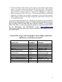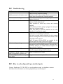
1
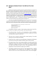
OPERATION MANUAL
For
Rotary Culture MW™-(RCMW™)
Continuous Flow Perfusion System
8044 El Rio
Houston, TX 77054
(T) 713-741-2582 (F) 713-741-2588
[email protected]
www.synthecon.com
V.5.2
8-13-08
Table of Contents
1.0
General introduction to the Rotary Culture Max™
2.0
Read before using--Limited Warranty
3.0
Getting Started-- Unpacking and Inspection
4.0
RCMW™ preparation required before culture initiation
4.1
System disassembly for washing & sterilization
4.2
Washing the RCMW™ Components after disassembly
4.3
Re-assembly after sterilization
5.0
Troubleshooting
6.0
How to order disposable pre-sterilized parts
7.0
Example Cell Culture Protocols for first time users
2
1.0 GENERAL INTRODUCTION TO THE ROTARY CULTURE
MAX™
Synthecon, Incorporated is the industry leader in the design and utilization of unique Rotary
Cell Culture Systems™ widely applicable in industrial, academic, and aerospace environments. A
great variety of cell types from different species have been successfully grown in these systems to date
including: osteoblasts, chrondrocytes, skeletal muscle, human and murine tumors, primary human
hepatocytes, a variety of human explant tissues, and fragile cell cultures unable to be cultivated in any
other system (see bibliography at the end of the manual and www.synthecon.com for a continuously
updated list). Cells have been successfully grown both in the absence of solid supports or using any of
a variety of support structures; i.e., microcarrier beads, collagen macro beads, alginate beads, and
various scaffolding materials. Cells subcultured in the unique bioreactor environment have been
shown to exhibit unique properties; i.e., enhanced gene expression, enhanced production of bioproducts, spontaneous formation of three-dimensional tissue assemblies, etc.
The advanced design ROTARY CULTURE MAX™ (RCMW™) represents the next generation
of Continuous Perfusion Bioreactors exclusively manufactured by Synthecon, Inc. The RCMW™
rotates the cell culture chamber horizontally to maintain the seeded cells suspended in the culture
medium and provides an exceptional cell culture environment that enhances cell growth through the
absence of air bubbles in the zero head space cell culture vessel,
minimal shear forces,
high mass transfer of nutrients,
effective waste removal, and
efficient oxygenation.
The RCMW™ incorporates a number of design changes providing increased applicability,
durability, and ease of use compared to earlier prototypes. These innovations include:
1. An advanced design cell culture vessel incorporating a dialysis membranecovered perfusion core which provides nutrient and gas exchange with cultured
cells without direct exposure to media flow.
2. The new in-line oxygenator system provides external gassing of the media
insuring a low stress culture environment
3. A new direct drive rotation system provides ease of operation and eliminates
the older belt driven pulley and gear assembly found in earlier systems.
4. For increased ease of use, access and serviceability, the culture vessel is now
rotated in a cradle roller assembly. The culture vessel is perfused through
rotating fluid couplings located at the vessel endcaps. For removal, simply lift
the culture vessel from the cradle for service, thus eliminating the need for
manipulation of metal shafts and complex gear assemblies.
5. The media circulation loop now has two 3-way stopcock valves to simplify
media management in the circulation loop. The RCMW™ is now equipped
with one media reservoir bottle located on the rear face of the vertical support.
3
The RCMW™ allows the growth and maintenance of a variety of cell and
tissue types in monocultures, co-cultured three-dimensional tissue-like cell aggregates
and explants. The RCMW™ accomplishes this by continuously perfusing fresh
nutrients and gas, and effectively removing of waste products while maintaining a
low shear suspension environment. The large 500 ml media reservoir along with the
culture chamber volume, insure an extended culture. The media reservoir being
outside the culture chamber, essentially, eliminates the need to remove the growth
chamber from the incubator to replenish the medium. The key advantages of a
perfused cell culture system include:
1. Ability for long-term un-interrupted cell culture
2. Clear unobstructed viewing of culture chamber environment.
3. Closed loop circulation of fluid, which reduces risk of contamination.
The RCMW™ is composed of the following components shown in Figure 1.
A.
Oxygenator assembly- externally facilitates oxygenation/CO2 exchange for
cell and tissue cultures in the vessel. The assembly is mounted on the face of
4
the vertical plate. The unit contains 46 square inches of surface area within
thin wall silicone tubing. The fluid volume is about 10 cc. The oxygenator is
easily removed for cleaning/sterilization. DO NOT REMOVE THE
TUBING FROM THE HOUSING. It is mounted on the upper left side of the
vertical plate of the support assembly.
.
B.
Peristaltic pump- clockwise rotation provides the force to pump culture
medium through the culture vessel. It is mounted on the far upper right side
of the vertical plate of the support assembly. Lift the tan colored faceplate
upward to gain access for insertion of the media circulation tubing. Power is
provided to the peristaltic pump via a multi-colored ribbon cable, which is
connected at the power supply and then at the pump. To insure proper
pumping, the tubing must be aligned in the center of the rotating rollers, and
locked into the v-notches on the inlet and outlet sides of the pump. The pump
flow rate is adjusted using the panel control knobs on the right front of the
power supply. One rpm on the peristaltic pump is approximately equivalent
to a flow rate through the circulation tubing of 0.5 ml/minute. Rate of flow is
governed by the pore size of the flat filter located on the culture vesselÕs
leeward endcap. Smaller pore sizes (3-10 micron) require reduced flow rates
to avoid damage from over-pressurization of the membrane. Higher flow rates
can be achieved with larger membrane pore sizes (100 micron). Larger pore
sizes must be specified when ordering flat filters.
C.
Culture media reservoir- a 500 ml Pyrex glass bottle with orange cap
containing a long stainless steel media supply tube that extends to the bottom
of the bottle, a short steel media return tube, and a Whatman micro filter to
vent the bottle. It is located in the middle of the rear face of the vertical plate
of the support assembly.
D.
Direct motor drive- used to rotate the culture vessel horizontally at speeds
from 2-42 rpm. It is equipped with one extended service life stepper motor
(no brushes or gear head). The rotational speed switch, located on the left
face of the power supply, has three settings: “Low”- adjustable range of 6-27
rpm; “Off” or “High” -adjustable range of 10-52 rpm.
E.
Perfusion Core- the plastic cylindrical core fits in the center of the culture
vessel. It is to be covered with a dialysis membrane. Media flows through
openings at either end of the core underneath the membrane. Media
exchange with the cell compartment occurs through the pores of the dialysis
membrane.
F.
Culture vessel- culture vessels can range in volume from 25 ml to 1L. The
standard size vessel is 125 ml. The vessel is composed of two white
polyacetyl endcaps. Affixed to the endcaps are white delrin luer fittings for
attaching rotating fluid couplings. Assembled, the vessel is comprised of two
white endcaps, a perfusion core, and a clear vessel wall. The vessel wall
5
contains two sampling/injection Luer lock ports with rubber septums and
drain/fill port with a Delrin plastic plug insert.
G.
Rotator Base/Assembly Support- serves to support and rotate the culture
vessel. It is constructed of two rectangular white Delrin/Acetyl plastic plates
(one horizontal and one vertical) creating an envelope 12" wide X 10" long X
10.5" high. Components are mounted on each of the plates. Located on the
vertical plate are the oxygenator assembly, peristaltic pump, and media bottle.
The roller cradle assembly is attached to the horizontal base plate. It consists
of two white Delrin uprights creating a roller cradle in which the vessel is
aligned, supported and rotated.
H.
Upright roller cradle supports- vertical white Delrin plastic plates equipped
with white Delrin direct-drive disk and roller support disk to maintain the
culture vessel in proper alignment in the roller cradle assembly.
I.
Silicone tubing standoff clips- be sure tygon tubing is inserted through the clip
and does not put strain on the rotating coupler. The rotating coupler must
remain parallel with the central axis throughout system rotation
J.
Power supply- the blue control box that houses the electronic motor speed
controls. The front panel knobs are used to adjust vessel rotation speed, as
well as, to control the peristaltic pump. A digital tachometer displays
rotation speed and rate of pump flow. A flat, multicolored, ribbon cable
connects the rotator base to the power supply control box. The rotational
speed of the vessel may be set on “Hi”, “Low”, or “Off”. THE CONTROL
BOX SHOULD NEVER BE PLACED INSIDE AN INCUBATOR.
K.
Connecting tubing- reusable, autoclavable Dow-Corning silicone rubber
tubing used to complete the perfusion loop (3/32" inner diameter)
External perfusion loop- consists of media supply/waste bottle, oxygenator assembly,
peristaltic pump, media and rotating fluid couplings with three-way valves,
connected with reusable, autoclavable, silicon rubber tubing.
6
2.0 READ BEFORE USING-LIMITED WARRANTY
þ Please read, complete and return the Limited Warranty Sheet found on the last
page immediately upon receipt of your new RCMW™. The Warranty will NOT
BE VALID unless it is signed and returned to Synthecon, Inc.
þ The RCMW™ is currently intended for RESEARCH USE ONLY (see warranty).
þ Caution: performing any of the following can invalidate the warranty.
ý Soaking any part of the vessel in bleach, acidic, or basic cleaning
solutions can result in absorption of toxic chemicals into the rubber
fittings and inhibit cell growth.
ý Abrasive cleaners or strong organic cleaning compounds such as
acetone will destroy the plastic.
ý Corrosive chemicals such as chromates will damage the metal
parts.
ý Do not autoclave the rotator base/upright assembly (see Figure 1).
Table 1 lists those components that can be autoclaved.
ý Sterilizing the autoclavable components (Table 1) for more than
the recommended temperature and time (120oC for 20 minutes).
ý Storage of the rotator base/upright assembly in an incubator while
NOT in use will corrode the motors eventually resulting in loss of
function. Synthecon reserves the right to make discretionary
determination of the cause of damage to returned rotators and deem
whether the repair is covered under the limited warranty.
ý Placing the power supply/control box inside an incubator will
result in loss of function.
7
Table 1 Methods for sterilizing RCMW™ components
Autoclavable components
120oC, 20 min
Culture vessel
(Drlrin core, Delrin drain/fill port, O-rings, two end
caps, clear vessel wall)
Silicone rubber tubing
0.2 micron vent filters
medium bottle & cap
oxygenator
male and female type tubing connectors
Do not autoclave
Wipe/rinse with ETOH only
White Delrin cradle support assembly
peristaltic pump
power supply outer cover
Ribbon cable
Disposable Components
(discard after each use)
Plastic three way stopcock with luer fittings
Rotating fluid couplings
Syringes
Rubber Septums
8
3.0 Getting Started- Unpacking and Inspection
The RCMW™ is carefully packaged for shipment to ensure the arrival of an
intact, functional unit. Unfortunately, on rare occasions, some damage may incur
during handling by the freight carrier.
l
Upon receipt, visually inspect each system component closely after unpacking for
visible or concealed damage.
l
IF DAMAGE IS EVIDENT OR SUSPECTED, DO NOT ASSEMBLE OR
OPERATE THE UNIT. Please call Synthecon, Inc. at (800) 853-0740 if you are
in the USA. For assistance outside the USA, please call your closest distributor
listed at the end of the manual.
4.0 RCMW™ preparation required before culture initiation
Before initiating the growth of cultures, the RCMW™ must be properly prepared.
Disassembly and discard of disposable components
Cleansing/washing of autoclavable components
Rinsing/soaking
Autoclaving appropriate components
Unit re-assembly
CAUTION: ALL RCMW™ COMPONENTS ARE NOT STERILE UPON
ARRIVAL EXCEPT THOSE IN STERIL PACKAGES
INCLUDING:
Three way stopcock/rotating fluid couplings
Cannulas and Septums
One way valves
The RCMW™ is shipped completely assembled with these non-sterile
disposable components attached for instructional use ONLY and must be
cleaned and sterilized, or discarded and replaced with pre-sterilized
components before use.
9
4.1 System disassembly sequence for washing &
sterilization
Please refer to Figure 1 for proper identification of parts to facilitate disassembly.
Remove the following items to wash and autoclave or for replacement with presterilized components before initializing a sterile cell culture in the RCMW
Upon receipt of the RCMW™ unit and prior to actual operation1. Disconnect disposable rotating coupling from each end of the culture vessel and
discard.
2. Carefully remove the culture vessel. Remove each of the white Delrin end caps
while holding the vessel (a plastic screw is included to assist with removing the
end caps. You will see screw holes in the Delrin end cap. Put the screw in one of
the holes and screw in until the end separated from the vessel wall. Remove
screw and reinsert into another hole to further separate the vessel from the end
cap. A slight unscrewing twist of the end cap will make it easier to remove).
Unscrew the white Delrin drain/fill port. Place all parts in a secure area where
they cannot be knocked onto the floor and become damaged.
3. Remove tubing from the support clips located on the outer face of the upright
support plates of the roller cradle.
4. Disconnect and remove the silicon rubber tubing forming the perfusion loop.
Note how the tubing is connected to facilitate re-connection after washing and
sterilization. Disconnect the tubing from the peristaltic pump. NOTE: leave the
tubing connected to the orange cap of the media bottle to facilitate re-assembly.
5. Remove the oxygenator assembly by gently removing the bolt on the bottom of
the white bracket. Support the assembly by using your fingers while removing the
oxygenator to prevent it from falling. DO NOT REMOVE TUBING FROM
OXYGENATOR HOUSING!
6. Remove the media bottle from the holder in the rear of the vertical plate of the
support assembly.
4.2
Washing the RCMW™ Components after disassembly
1. Use a mild liquid soap— a laboratory soap such as Liquinox or equivalent.
2. Soak all components (disassembled culture vessel,oxygenator, media bottle,
connecting tubing) in the soap dissolved in warm water for about 10 minutes.
3. The RCMWª may be washed with a soft brush. Avoid sharp instruments as any
damage to the vessel wall can cause progressive cracking after multiple
autoclavings.
10
The oxygenator requires an injection of soapy water using a 20-60 cc size
syringe and then allowed to soak.
4. After cleansing, thoroughly rinse the components by first carefully transferring
them to a scrupulously clean bucket containing fresh tap or deionized water. (Do
not use a bucket or container that has been used with toxic chemicals or
detergents). Rinse each component under gently running water until all traces of
soap are completely removed.
5. The oxygenator will need to be rinsed by injecting water through the tubing or
syringe port using a 20-60 cc size syringe several times. REMEMBER: DO
NOT REMOVE THE TUBING FROM THE OXYGENATOR HOUSING.
6. Either of two rinsing protocols can be used.
Rinsing the components is a critical step since residual soap can be harmful to
cell cultures. First, hand rinse all components in high purity, cell culture grade
water (i.e., Millipore Milli Q water or the equivalent). Next, either
1. Completely immerse and soak all components in high purity water
overnight or
2. Alternatively, rinse components in continuously running
high purity (Milli Q or equivalent not deionized)water for 45-60
minutes.
(Do not forget to use a syringe to rinse the oxygenator) least 6
times with high purity water).
7. The perfusion core with the membrane attached must be autoclaved separately
from the other components. A piece of dialysis membrane is cut to a length
slightly larger than the distance between the two inner grooves of the perfusion
core. The membrane is hydrated in deionized water for approximately 10
minutes. The membrane is opened by gently rubbing between the thumb and
forefinger. After opening, the membrane is gently pulled over the perfusion core
(This process can be assisted with a blunt forceps being careful to pull to
membrane at the end. If the membrane is punctured, it must be replaced). The
dialysis membrane is held in place with o-rings, which are installed with the
conical plastic o-ring tool. The o-ring is slipped over the narrow end of the tool
and stretched by pushing toward the large end. The tool is then placed over the
end of the perfusion core and the o-ring rolled on to the core and into the groove
to secure the membrane. After placing o-rings at both ends, any excess
membrane can be trimmed. After the membrane is mounted on the core it can be
sterilized by one of several methods depending on the composition of the
membrane. Regenerated cellulose membranes may be autoclaved at 121O C for
15 min. if completely immersed in deionized water. Cellulose ester membranes
may be sterilized in 70% ETOH, preferably overnight. After exposure to ETOH,
11
the membranes should be rinsed with sterile water or media. PVDF membranes
can be autoclaved dry at 121O C.
The Perfusion core with the mesh membrane can be autoclaved with other
components as stated in 9
8. Prepare components for autoclaving by wrapping (i.e., autoclave bags or
aluminum foil) and secure with autoclave tape. The culture vessel should be
autoclaved disassembled.
REFER TO THE LIST IN TABLE 1 FOR THE COMPONENTS THAT CAN
BE AUTOCLAVED.
9. Autoclave components at 120oC for 20 minutes. A second cycle of autoclaving at
120oC for 20 minutes can be performed if desired but should be unnecessary.
CAUTION: Higher temperatures and longer autoclave times must be avoided as
these can damage components and void the warranty.
10. For ETO (Gas) Sterilization, wash the RCMW™ components as described above.
Open all ports and wrap the system in a gas permeable material. After gas
sterilization, it is not necessary to perform an “air soak”. In the hood, fill the
system and culture vessel with sterilized high purity water that has been made
slightly acidic with a few drops of concentrated hydrochloric acid (HCL).
Connect the waste line to the culture vessel and circulate the acidic water for at
least 8 hours (overnight). ETO is more soluble in acid water and will be
completely removed using this method.
Since gas sterilization is performed at lower temperatures, this will likely extend
the life of the culture vessel. However, ETO is toxic to cell cultures and residual
ETO will be present in the system. It is, therefore, necessary to rinse carefully
and completely as described above in step 6.
12
4.3 Re-assembly after sterilization
Refer to Figure 1 for guidance in re-assembly.
1. Allow the sterilized components to cool to room temperature before attempting
re-assembly. Failure to do so will result in misalignment of components due to
thermal expansion.
Take all sterilized components to a sterile work area; i.e., a laminar flow
biological safety cabinet (sterile tissue culture hood).
Carefully unwrap the culture vessel wall and endcaps. Install one endcap in the
wall. Pick up the perfusion core with a sterile forceps and place it in the
counterbore in the inner face of the endcap. Take the other endcap and place it
onto the perfusion core. Press the endcaps together until they are flush with the
clear vessel wall. Try to avoid touching the fill port or sampling ports. If these
areas are accidentally touched, wipe them immediately with a sterile alcohol
swab. Press the plug into the fill port and affix rubber septums to the luer
sampling ports. Attach a disposable, pre-sterilized rotating coupling and threeway valve to both ends of the culture vessel. Place the culture vessel in the roller
cradle of support assembly/rotator base (in the hood).
To complete assembly of the culture vessel prior to filling with media, attach the
autoclaved oxygenator assembly and tubing as shown in figure 1
2. Filling the Culture vessel with media. Fill the media bottle with the desired
volume of media. Remove the fill port plug on the vessel wall and place it on a
alcohol swab. Fill the cell chamber of the vessel with media and cells until it
reaches the fill port. Microcarriers or other scaffolding material can also be added
at this time. Replace the fill port plug being careful not to contaminate the plug.
3. Open the cover of the peristaltic pump so that the tubing is not pinched. Place a
20-60 ml sterile syringe on one of the luer ports on the rotating coupling and turn
the valve to open that port. Using the syringe, prime the tubing by drawing
media from the bottle until it reaches the syringe. Rotate the valve so that the
media flow is directed into the vessel through the perfusion core. Close the cover
of the peristaltic pump. Place a 5 or 10 ml syringe with a plastic canula on the
sampling port (wiping the septum with a sterile alcohol swab whenever it is to be
punctured is recommended). Maneuver the bubble in the cell chamber beneath
the sampling port and draw the bubble out. Media will be pulled through the
membrane to replace the volume of the bubble. During the culture, if bubbles
appear in the vessel, they can be removed by this procedure. The tubing directly
attached to the rotating coupling should be inserted into the support clips to
prevent the rotating coupling from wobbling, which will cause excessive wear and
result in failure of the coupling. The system is now ready to be placed in an
incubator and connected to the power supply.
13
4. Connect the ribbon cables from the power supply to the peristaltic pump and the
rotator. The cables can be run between the door and the gasket. The rotational
speed is usually set to 10-12 rpm initially. If visible aggregates are formed, the
speed should be adjusted upward to maintain the aggregates in suspension
without touching the wall of the vessel. The pump speed should be determined
empirically according to the metabolic requirements of the cells being cultured.
Media changes can be done by simply changing the media bottle in the flow loop
to one with fresh media.
No special medium formulations are required for the growth of cells in the RCCS.
Each cell type and application is unique. Cell culture medium formulations that you
have previously used successfully with other cultivation methods (i.e., petri dishes,
flasks, roller bottles, etc.) have generally been found to be appropriate for the RCCS.
See the Bibliography and SYNTHECON website www.synthecon.com
(bibliography periodically updated) for medium formulations successfully used in the
past with the RCCS.
Selected list of type and cell numbers successfully cultured in
the Rotary Cell Culture System™
Type of cells
Chondrocytes
Human intestine mesenchymal
Thyroid
Rat PC12
LNCaP human prostate
LN1 mixed mullerian human
ovarian cancer
Human cervical primary tumor
16 different tumor cell lines
MIP 101 human colon cancer
HepG2 human hepatoblastoma
HT-29 colon adenocarcinoma
cells/ml
inoculated
5
Reference
5-6 X 10
2 X 10⁵
4 X 10⁵
5.5 X 10⁵
2 X 10⁵
Baker & Goodwin, 1997
Goodwin et al., 1993
Martin et al., 2000
Lelkes et al., 1998
Zhau et al., 1997
2 X 10⁵
2 X 10⁵
5-20 X 105
3 X 10⁵
1 X 10⁶
2 X 10⁵
Goodwin et al., 1992
Chopra et al., 1997
Ingram et al., 1997
Francis et al., 1997
Khaoustov et al., 1999
Goodwin et al., 1992
14
5.0 Troubleshooting
Problem
Possible cause/solution
Check for loose connection tubing
Incubator could be dry causing excessive evaporation
Ensure that the media bottle contains medium
Culture medium leaking
Check valves, couplings, and tubing for tightness of fit
Replace if defective
Medium fails to recirculate
Check for proper positioning of steel tube below the
fluid level in the media bottle
Check position of three way valves and rotating
coupling
Make certain peristaltic pump is plugged in and speed
control set on power supply
Insure that tubing is correctly installed in the roller
assembly of the peristaltic pump
Vessel rotation is inconsistent
Check that vessel is properly situated in the roller
cradle and is not bound up or jammed.
The vessel can only achieve rotation if it is in contact
with the rotating disk drive located on the inside of the
left upright cradle support.
Check to insure that the RPM are optimal for the
selected high/low range of the power supply
Perfusion tubing twisting
Check that rotating coupling was installed and aligned
appropriately with the tubing support clips and that it
is turning without an orbital rotation. Replace and
align correctly if defective
Culture vessel will not fill
Check position of three-way stopcock valves
Look for crimp in tubing at inflow endcap
Oxygenator tubing removed from Return to Synthecon for repair
inside of oxygenator cylinder core
Media leaking from filter on top of Empty waste bottle and replace filter unit
waste bottle
Bubbles present in cell culture vessel
6.0 How to order disposable pre-sterilized parts
Contact Synthecon (713-741-2582 or [email protected]) or telephone contract
distributors for information on ordering disposable pre-sterilized parts.
15
7.0 Example Cell Culture Protocols for first time users
It is often instructional for first time users of the system to become acquainted with
the RCCS by first using the system with an established protocol before proceeding to
actual experiments.
If microcarrier beads or scaffolding will be used, they should be prepared first for
inoculation into the vessel according to the manufacturer’s instructions. An example
protocol for microcarrier beads is provided below.
Pharmacia Cytodex 3 Microcarrier Beads
The properties of these beads are as follows: a density of 1.04 g/ml, 175 µm size, a
swelling factor of 15 ml/g dry weight, and 3 X 10⁶ microcarriers/g dry weight.
Cytodex 3 consists of a layer of denatured collagen coupled to dextran beads. It is
the microcarrier of choice for cells known to be difficult to grow in culture, for
differentiated cell culture systems and cells with an epithelial-like morphology. It is
commonly used as a general purpose microcarrier.
1. Weigh 1 gram of the dry microcarrier beads on a suitable balance and place into a
100 ml clean glass bottle. (Bottle should be pretreated with a siliconizing agent
according to the manufacturer’s instructions or excessive loss of beads will occur
due to adherence to the glass).
2. Add 50-100 ml of 1X Ca2+ and Mg2+ free phosphate buffered saline (PBS) to
the bottle and incubate at room temperature for at least 3 hours to allow the
beads to swell.
3. Remove supernatant by aspirating with a Pasteur pipette and vacuum source.
4. Wash microcarriers once with gentle agitation for a few minutes with PBS w/o
Ca2+ and Mg2+. Use 30-50 ml/g Cytodex of PBS.
5. Discard PBS and replace with fresh PBS w/o Ca2+ and Mg2+ adding 30-50
ml/g Cytodex of PBS.
6. Sterilize by autoclaving at 115oC, 15 min, 15 psi. Make certain that the cap of
the bottle is loose before sterilization. CAUTION: If microcarriers are
autoclaved at higher temperatures and/or longer time intervals, beads may turn
brown and performance affected.
7. Prior to use, sterilized microcarriers are allowed to settle, the supernatant
removed by aspiration as above and microcarriers rinsed in warm 37oC culture
medium (serum is not required in culture medium).
16
8. Microcarriers are now ready to use for culturing and are extremely stable.
Cytodex that has been hydrated and sterilized as above can be stored sterile in
PBS for at least two years at 4oC.
Practice Protocol for Cell Culture using Cytodex 3 microcarrier
beads
Perform procedures in a biological safety cabinet (sterile tissue culture hood).
1. A commonly available cell line to use for practice is baby hamster kidney (BHK21). These can be obtained from the American Type Culture Collection
(Rockville, MD) or colleagues. Alternatively, the same protocol can be used with
MCF-7, a breast cancer cell line, also available from ATCC.
2. Before beginning, obtain a sterilized Synthecon cell culture vessel and rinse with
culture medium or phosphate buffered saline as described in Section 4.2.6.
3. Remove BHK-21 cells from culture flasks or dishes: Remove culture medium,
add 0.25% trypsin/0.075% EDTA, incubate for 3-5 minutes. Check at minimum
time to determine if cells are detaching from flask/dish by observation with an
inverted microscope. Be careful not to over expose cells to trypsin/EDTA as this
can result in loss of cell viability.
4. After determining that the cells are detaching from the culture flask/dish by
observation in an inverted microscope, add sterile, pre-warmed DMEM culture
medium (containing 10% fetal bovine serum and penicillin/streptomycin or other
antibiotic).
5. Remove the cells from the culture flask/dish by vigorously pipetting the medium
(with the assistance of a Pipet Aid device) across the entire cell growth surface at
least 5 times. This ensures that all cells are removed and facilitates creation of a
single cell suspension. Inadequate pipetting of the cell suspension will result in a
clumpy cell suspension which will not produce optimum results.
6. Place cell suspension in a sterile tube. Determine cell number using either a
Coulter counter or hemocytometer.
7. Inoculate cells at a final concentration of 2-4 X 10⁵/ml and microcarriers at 5
mg/ml (4,000 beads/mg) according to instructions in Section 5.
8. Place inoculated vessel carefully onto the rotator base. Place rotator base into the
culture incubator. Make certain that the ribbon cables are connected between the
rotator base and power supply and that the power supply is plugged in. Begin the
vessel rotation at a speed of 10-12 rpm.
17
9. The day after culture initiation, take a sample. If available, use a Beckman
glucose analyzer and blood gas analyzer to assess glucose use, dO2, dCO2, and
pH. Part of the sample should be placed in a small petri dish or on
hemocytometer for observation. Cells should be visibly attached to the beads and
some beads may be aggregated together in groups of two or three.
10. Day 3- Change medium according to procedures in Section 6 above and take
another cell sample. Cell viability can be checked using trypan blue dye
exclusion assay (Goodwin et al., 1992).
11. Day 4- A mixture of bead aggregates ranging from 2-16 should be seen.
Practice Protocol for Cell Culture without solid support
1. Before beginning, obtain a sterilized Synthecon cell culture vessel rinse with
culture medium or phosphate buffered saline as described in Section 4.2.6
2. Remove cells from culture flask/dish as described in the protocol for microcarrier
beads above.
3. Determine the number of cells/ml using a Coulter counter or hemocytometer.
Inoculate 8-1.0 X 10⁶ cells/ml into the vessel.
4. Place inoculated vessel carefully onto the rotator base. Place rotator base into the
culture incubator. Make certain that the ribbon cable is connected between the
rotator base and power supply and that the power supply is plugged in. Begin the
vessel rotation at a speed of 10-12 rpm.
5. The day after culture initiation, take a sample according to the procedures
described in Section 7 above. If available, use a Beckman glucose analyzer and
blood gas analyzer to assess glucose use, dO2, dCO2, and pH. Part of the sample
should be placed in a small petri dish or on hemocytometer for observation. Cells
should have aggregated and formed loose aggregates.
6. Change medium on days 2 and 4. Loose aggregates will be observed to condense
and may form rounded structures.
18
Equipment Usage Rights
SYNTHECONTM Inc. grants the purchaser a non-exclusive right to use the Rotary Cell Culture
System equipment solely for the purpose of conducting research and specifically excluding use of
this equipment for any purpose other than research. Synthecon technology is not intended for use
on/in humans. Any desire by end user to manufacture commercial products in Synthecon, Inc.
technology will require the end user to obtain a User’s License from the National Aeronautics and
Space Administration and/or Synthecon, Inc. Its use must comply with all laws, ordinances, and
regulations relating to the possession, use, or maintenance of the equipment, including
registration and/or licensing requirements, if any.
Patents in Force
The Rotary Cell Culture System™ is protected by patents exclusively licensed from the National
Aeronautics and Space Administration (NASA) and patents owned by Synthecon Inc., with others
pending. The patents Synthecon Incorporated operates under are listed below:
•
•
•
•
•
•
•
•
•
•
•
Patent number 5,437,998 “GAS PERMEABLE BIOREACTOR AND METHOD
OF USE” Patent issued August 1, 1995
Patent number 5,665,594 “GAS PERMEABLE BIOREACTOR AND METHOD
OF USE” Patent issued September 9, 1997
Patent number 5,702,941 “GAS PERMEABLE BIOREACTOR AND METHOD
OF USE” Patent issued December 30, 1997
Patent number 5,763,279 “GAS PERMEABLE BIOREACTOR AND METHOD
OF USE” Patent issued June 9, 1998
Patent number 4,988,623 “ROTATING BIO-REACTOR CELL CULTURE
APPARATUS” Patent issued January 29, 1991
Patent number 5,026,650 “HORIZONTALLY ROTATED CELL CULTURE
SYSTEM WITH A COAXIAL TUBULAR OXYGENATOR” Patent issued June
25, 1991
Patent number 5,153,131 “HIGH ASPECT RATIO VESSEL AND METHOD OF
USE” Patent issued October 6, 1992
Patent number 5,155,035 “METHOD FOR CULTURING MAMMALIAN
CELLS IN A PERFUSED BIOREACTOR” Patent issued October 13, 1992
Patent number 5,153,133 “METHOD FOR CULTURING MAMMALIAN
CELLS IN A HORIZONTALLY ROTATED BIOREACTOR” Patent issued
October 6, 1992
Patent number 5,998,202 “MULTIPLE CHAMBER DIFFUSION VESSEL”
Patent issued December 7, 1999
Patent number 5,989,913 “CULTURE VESSEL FOR GROWING OR
CULTURING CELLS, CELLULAR AGGREGATES, TISSUES AND
ORGANOIDS AND METHODS FOR USING THE SAME” Patent issued
November 23, 1999
Alterations
Alteration of the equipment voids the warranty on this equipment. In no case shall
TM
SYNTHECON , Inc. be responsible for any modifications or alterations to this equipment
TM
performed by anyone other than SYNTHECON , Inc.
19
IMPORTANT NOTICE
Limited Warranty: Limited Liability
TM
SYNTHECON Inc. warrants that, for one year, under normal operating conditions and use, this
TM
equipment will be free from defects of materials and workmanship. SYNTHECON Inc. will
TM
repair or replace defective parts at our option. Contact SYNTHECON Inc. immediately upon
TM
discovery of a defect. SYNTHECON will provide you with a return authorization number and
shipping instructions.
Components
Oxygenator Membrane
The oxygenator membrane is a very delicate component consisting of silicone rubber, .005 inches
thick, covering a polyester cloth backing. Care and attention should be given to the membrane
during cleaning, sterilization, and removal of cultured material. Synthecon reserves the right to
make discretionary determination as to the cause of damage with returned oxygenators, and deem
whether the repair is covered under the Synthecon Limited Warranty. See Operators Manual for
appropriate procedures.
Rotator Base
Storage of the Rotator Base in an incubator while not in use will result in damage to the rotator
components. Synthecon reserves the right to make a discretionary determination as to the cause
of damage with returned rotators, and deem whether the repair is covered under the Synthecon
Limited Warranty.
The equipment must be used and operated in a careful and proper manner. In no event shall
TM
SYNTHECON Inc. or its suppliers be liable for any indirect, special, or consequential damages,
including but not limited to, loss of cells, medium, data, labor or equipment incurred by the
purchaser or any third party arising from the use of, or inability to use this equipment.
Service
TM
For service during and after the expiration of the warranty, contact SYNTHECON , Inc. at (713)
741-2582 during 9 a.m. to 5 p.m., US Central Time Zone. Equipment being returned for service
should be shipped to: Synthecon,- Customer Service Dept, 8044 El Rio, Houston, TX. 77054.
Please include a short description of the problem, service required or reason for the return. Please
pack equipment being returned in sturdy containers with adequate packing materials. Synthecon
will not be liable for damage sustained during shipment.
TM
SYNTHECON , Inc. also provides biology and engineering contract support services. Special
custom designed equipment can be built to meet the customer’s needs. Customers can provide
TM
cell samples of their cell and tissue lines, and SYNTHECON Inc. will conduct growth and
feasibility studies of the customer’s cells on a contract fee basis. Sub-licenses are available which
would include design, scale-up, and manufacture of production equipment.
20
Copying and Sale
Duplication, modification or sale of copies of this equipment is prohibited. This equipment is
TM
patented by the U.S. Government. SYNTHECON Inc. holds the exclusive licenses to these
patents.
Acceptance of Equipment
The purchaser shall inspect the equipment delivered and immediately notify the seller of any
discrepancies with the equipment. If the purchaser fails to provide notice in writing within 14
days after the delivery of the equipment, the purchaser will be presumed to have accepted the
equipment. The acceptance and use of this equipment constitutes an agreement upon the
purchaser’s part to the usable condition of the equipment.
Refurbished Products
Refurbished products carry a separate warranty; this warranty does not apply. For details of the
refurbished product warranty, please refer to the refurbished product warranty information
packaged with each refurbished product.
WARRANTY WILL NOT BE VALID IF IT IS NOT SIGNED AND RETURNED.
Warranty valid to original purchasers only. Please sign and return by mail immediately to: For
international locations see the last page of this manual
Synthecon, Inc.
Customer Service Department
8044 El Rio
Houston, TX 77054
Purchaser:
Institution/Organization:
Purchase Date:
Invoice/PO#:
Model #:
Serial Number(s)
PLEASE NOTE THAT THIS AND THE NEXT PAGE ARE FOR YOUR
RECORDS. PLEASE USE THE YELLOW PAGE THAT ACCOMPANIES THIS
MANUAL FOR WARRANTY REGISTRATION!
21
IMPORTANT NOTICE
PLEASE READ AND COMPLETE THE SYNTHECON LIMITED
WARRANTY ON THE LAST PAGE
RETURN THE YELLOW COPY IMMEDIATELY
WARRANTY WILL NOT BE VALID IF NOT COMPLETED AND RETURNED
WARRANTY VALID TO ORIGINAL PURCHASERS ONLY
IMPORTANT NOTICE
PLEASE READ AND COMPLETE THE SYNTHECON LIMITED
WARRANTY ON THE LAST PAGE
RETURN THE YELLOW COPY IMMEDIATELY
WARRANTY WILL NOT BE VALID IF NOT COMPLETED AND RETURNED
WARRANTY VALID TO ORIGINAL PURCHASERS ONLY
IMPORTANT NOTICE
PLEASE READ AND COMPLETE THE SYNTHECON LIMITED
WARRANTY ON THE LAST PAGE
RETURN THE YELLOW COPY IMMEDIATELY
WARRANTY WILL NOT BE VALID IF NOT COMPLETED AND RETURNED
WARRANTY VALID TO ORIGINAL PURCHASERS ONLY
22
10 International Locations
USA
SYNTHECON, INC.
8044 El Rio
Houston, TX 77054
Tel.: (713) 741-2582
Fax: (713) 741-2588
[email protected]
Europe
Cellon
29 Am Bechler
L-7213 Bereldange
Luxembourg
Tel.: (352) 26 33 73 - 1
Fax: (352) 311 052
www.cellon.lu
e-mail: [email protected]
China
EQUL CORP.
Rm.1205, #10 Bldg., 168 HongQiao
Rd.,
Xuhui District, Shanghai 200030,
P.R.China
Tel: 86-21-51096009
Fax: 86-21-23010002
mailto:[email protected]
http://www.equl.com
Taiwan
Tseng Hsiang Life Science LTD.
No 99-15
Sec. 2, Nan-Kang Rd
Taipei, Taiwan R.O.C
Tel: 02-785-1156
Fax: 02-788-5896
[email protected]
Japan
Tomy Digital Biology Co., Ltd.
“EDGE” Building
2-9-1 Ikenohata Taito-ku Tokyo 1100008
Tel: 81-3-5834-0810
Fax: 81-3-5834-1888";
E-mail: [email protected]
Website: www.digital-biology.co.jp
Egypt
Noor Scientific & Trade
10 El-Salam St, Komish El-Nile
Aghakhan, Shoubra, Cairo-11241
Egypt
Tel: 202 4329148
Fax: 202 2034350
[email protected]
Korea, Singapore, and Malaysia
DayMoon Industries
P.O. Box 4585
Cerritos, CA 90703-4585
Tel: 714-542-5156
Fax:714-542-6131
[email protected]
India
Medi Analytika India Pvt. Ltd
Adyar Bridge road
Adyar, Madras - 600 020
India
Tel: 0091-44-446 0988/490
8734/490 8572
Fax: 0091-44-446 3931/490 8572
[email protected]