1
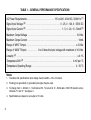
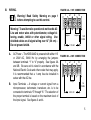
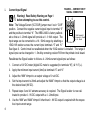
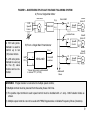
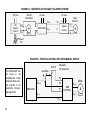
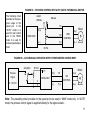
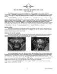
INSTALLATION AND OPERATING INSTRUCTIONS
MODEL KBSI-240D
Signal Isolator KB Part No. 9431
KBSI-240D
P1
J1
VOLT
CUR
MIN
MAX
1
2
!
3
4
5
6
7
8
9
10
See Safety Warning on Page 1
The information contained in this manual is intended to be accurate. However, the Manufacturer retains the right to make
changes in design which may not be included herein.
™
A COMPLETE LINE OF MOTOR DRIVES
© 2000 KB Electronics, Inc.
TABLE OF CONTENTS
Section
Page
i.
Safety Warning . . . . . . . . . . . . . . . . . . . . . . . . . . . . . . . . . . . . . . . . . . . . . . . . . . . . . . . . . . . . . . . 1
I.
Introduction . . . . . . . . . . . . . . . . . . . . . . . . . . . . . . . . . . . . . . . . . . . . . . . . . . . . . . . . . . . . . . . . . 2
II.
Mounting . . . . . . . . . . . . . . . . . . . . . . . . . . . . . . . . . . . . . . . . . . . . . . . . . . . . . . . . . . . . . . . . . . . 2
III. Wiring . . . . . . . . . . . . . . . . . . . . . . . . . . . . . . . . . . . . . . . . . . . . . . . . . . . . . . . . . . . . . . . . . . . . . 5
IV. Output Signal . . . . . . . . . . . . . . . . . . . . . . . . . . . . . . . . . . . . . . . . . . . . . . . . . . . . . . . . . . . . . . . . 9
V.
Limited Warranty . . . . . . . . . . . . . . . . . . . . . . . . . . . . . . . . . . . . . . . . . . . . . . . . . . . . . . . . . . . . 14
Tables
1.
General Performance Specifications . . . . . . . . . . . . . . . . . . . . . . . . . . . . . . . . . . . . . . . . . . . . . . . 4
2.
Voltage Input Signal . . . . . . . . . . . . . . . . . . . . . . . . . . . . . . . . . . . . . . . . . . . . . . . . . . . . . . . . . . . 7
Figures
1.
Control Layout & Mechanical Specifications . . . . . . . . . . . . . . . . . . . . . . . . . . . . . . . . . . . . . . . . . 3
2A. 115V Connection . . . . . . . . . . . . . . . . . . . . . . . . . . . . . . . . . . . . . . . . . . . . . . . . . . . . . . . . . . . . . 5
2B. 230V Connection . . . . . . . . . . . . . . . . . . . . . . . . . . . . . . . . . . . . . . . . . . . . . . . . . . . . . . . . . . . . . 5
3.
Current Input Signal Connection . . . . . . . . . . . . . . . . . . . . . . . . . . . . . . . . . . . . . . . . . . . . . . . . . . 6
4.
Voltage Input Signal Connections . . . . . . . . . . . . . . . . . . . . . . . . . . . . . . . . . . . . . . . . . . . . . . . . . 7
5A. Master/Multiple Slave Voltage Following System (Single Main Motor) . . . . . . . . . . . . . . . . . . . . . . 9
5B. Master/Multiple Slave Voltage Following System (Single Main Potentiometer) . . . . . . . . . . . . . . . . 9
6A Master/Slave Voltage Following System . . . . . . . . . . . . . . . . . . . . . . . . . . . . . . . . . . . . . . . . . . . 10
6B. Process Control with Auto/Manual Switch . . . . . . . . . . . . . . . . . . . . . . . . . . . . . . . . . . . . . . . . . . 10
6C. Process Control with Auto (Ratio Pot)/Manual Switch . . . . . . . . . . . . . . . . . . . . . . . . . . . . . . . . . 11
6D. Auto/Manual Operation with Potentiometer on KBSI Input . . . . . . . . . . . . . . . . . . . . . . . . . . . . . . .11
ii
i.
!
SAFETY WARNING! Please read carefully:
Be sure to follow all instructions carefully. Fire and/or electrocution can result due to improper
use of this product.
This product should be installed and serviced by a qualified technician, electrician, or electrical
maintenance person familiar with its operation and the hazard involved. Proper installation,
which includes wiring, mounting in proper enclosure, fusing or other over current protection and
grounding, can reduce the chance of electric shocks, fires, or explosion in this product or products used with this product, such as electric motors, switches, coils, solenoids, and relays. Eye
protection must be worn and insulated adjustment tools must be used when working with control under power. This product is constructed of materials (plastics, metals, carbon, silicon, etc.)
Which may be a potential hazard. Proper shielding, grounding, and filtering of this product can
reduce the emission of radio frequency interference (RFI) which may adversely affect sensitive
electronic equipment. If information is required on this product, contact our factory. It is the
responsibility of the equipment manufacturer and individual installer to supply this safety warning to the ultimate user of this product. (SW effective 11/92)
This product complies with all CE directives pertinent at the time of manufacture. Contact
factory for detailed installation instructions and Declaration of Conformity.
1
I.
INTRODUCTION
The KBSI-240D Signal Isolator is used to isolate, amplify and condition DC voltage and current
signals from any source (motors, tachs and transducers) which will drive most variable speed
motor controls with a voltage following input. The maximum output voltage of the isolator is 10
volts, which is a linear function of the input signal.
The KBSI-240D is versatile since it can accommodate a wide range of input voltages (0 - 25*,
0 - 120 and 0 - 550V DC) and, in addition, a wide range of input current signals (4 - 20 mA, 10
- 50 mA and 1 - 5 mA). The Voltage/Current (“VLT/CUR”) jumper is used to change the
KBSI-240D from a voltage to current input.
A built-in power supply enables the KBSI-240D to be controlled with a 5KΩ remote potentiometer (connect potentiometer to terminals “P1,” “5” and “6” – see page 9). The potentiometer can also be wired for Auto/Manual Operation.
*The input range of 0 - 25V is the maximum voltage that can be applied to terminals “5” and
“6”. The minimum input voltage is 0 - 5 volts, which can achieve an output voltage of 0 - 10
volts. The unit is factory calibrated so that a 0 - 10V DC input yields a 0 - 10V DC output.
II.
2
MOUNTING
Mount the Signal Isolator using (4) 6-32 screws (not included). Use the Control Layout and
Mechanical Specifications drawing on page 3 to locate the mounting holes. The unit is
designed to be mounted in any position providing its components do not come in contact with
grounded or live wiring.
FIGURE 1 – CONTROL LAYOUT & MECHANICAL SPECIFICATIONS (INCHES / [mm])
(Illustrates Factory Setting of Jumpers and Approximate Trimpot Settings)
4.843
[123.00]
0.276
[7.00]
0.276
[7.00]
4.291
[109.00]
KBSI-240D
P1
J1
VOLT
CUR
MIN
MAX
1
2
3
4
5
6
7
8
9
2.244
[57.0]
2.795
[71.0]
10
(4) mounting holes for #6 screws
3
TABLE 1 – GENERAL PERFORMANCE SPECIFICATIONS
AC Power Requirements . . . . . . . . . . . . . . . . . . . . . . . . . 115 or 208 - 230V AC, 50/60 Hz (1)
Signal Input Voltage (2) . . . . . . . . . . . . . . . . . . . . . . . . . . . . . . . 0 - 25, 0 - 120, 0 - 550V DC
Signal Input Current (2) . . . . . . . . . . . . . . . . . . . . . . . . . . . . . . . . . 1 - 5, 4 - 20, 10 - 50mA (3)
Maximum Output Voltage . . . . . . . . . . . . . . . . . . . . . . . . . . . . . . . . . . . . . . . . . . . . . 10 Volts
Maximum Output Current . . . . . . . . . . . . . . . . . . . . . . . . . . . . . . . . . . . . . . . . . . . . . . . 10mA
Range of “MIN” Trimpot . . . . . . . . . . . . . . . . . . . . . . . . . . . . . . . . . . . . . . . . . . . . . . ± 3 Volts
Range of “MAX” Trimpot . . . . . . . . . . 0 to 2 times the input voltage with maximum of 10 Volts
Linearity (4) . . . . . . . . . . . . . . . . . . . . . . . . . . . . . . . . . . . . . . . . . . . . . . . . . . . . . . . . ± 0.1%
Temperature Drift (4) . . . . . . . . . . . . . . . . . . . . . . . . . . . . . . . . . . . . . . . . . . . . . 4 mV per ºC
Temperature Operating Range . . . . . . . . . . . . . . . . . . . . . . . . . . . . . . . . . . . . . . . . 0 - 50 ºC
Notes:
1. To achieve full specifications input voltage must be within ± 10% of nominal.
2. Floating (non-grounded) or grounded input signal may be used.
3. To change from 4 - 20mA to 1 - 5mA remove R3. To convert to 10 - 50mA add a 150Ω 1W resistor across
terminals “5” and “6.” See figure 3.
4. Specifications are based on an output of 10 volts.
4
III.
FIGURE 2A – 115V CONNECTION
WIRING.
!
Warning! Read Safety Warning on page 1
before attempting to use this control.
Warning! To avoid erratic operation do not bundle AC
Line and motor wires with potentiometer, voltage following, enable, inhibit or other signal wiring. Use
shielded cables on all signal wiring over 12” (30 cm) –
Do not ground shield.
A.
B.
AC Power – The KBSI-240D is powered with either 115
or 230V AC, 50/60 Hz by arranging the jumpers
between terminals “1” to “4” properly. See figures 2A
and 2B. Be sure unit is wired in accordance with the
National Electric Code and other codes that may apply.
It is recommended that a 1 amp fuse be installed in
series with the AC line.
Input Terminals – A voltage or current signal from a
microprocessor, tachometer, transducer, etc. is to be
connected to terminals “5” through “8.” The selection of
the proper terminal is based on the maximum level of
the input signal. See figures 3 and 4.
1
2
3
Jumper
4
Jumper
1A
FUSE
115V AC
FIGURE 2B – 230V CONNECTION
1
2
3
Jumper
4
1A
FUSE
230V AC
5
i.
Current Input Signal
!
Warning! Read Safety Warning on Page 1
before attempting to use this control.
FIGURE 3 – CURRENT INPUT
SIGNAL CONNECTION
5
6
Note: The Voltage/Current (VLT/CUR) jumper must be in “CUR”
position. Connect the negative current signal input to terminal “5”
and the positive to terminal “6.” The KBSI-240D is factory calibrat150Ω Resistor
Converts 4 - 20mA
ed so that a 4 - 20mA signal will provide a 0 - 9 Volt output. The
to 10 - 50mA
–
+
input range can be converted to a 10 - 50mA range by attaching a
4 - 20mA
150Ω 1W resistor across the current input terminals “5” and “6.”
See figure 3. Control must be recalibrated when the 150Ω resistor is installed. The range of
signal input can be changed to 1 - 5mA by removing resistor R3 from the printed circuit board.
Recalibrate the Signal Isolator to follow a 4 - 20mA current signal input as follows:
6
1.
Connect a 10V DC meter (digital DC meter is suggested) to terminals “9”(-) & “10” (+).
2.
Apply the minimum input current (4mA) at terminals “5” and “6.”
3.
Adjust the “MIN” trimpot to an output voltage of 0 volt DC.
4.
Set the input current to 20mA and adjust the “MAX” trimpot so that the output voltage is at
the desired level (9V DC).
5.
Repeat steps 3 and 4 if extreme accuracy is required. The Signal Isolator is now calibrated to provide 0 - 9V DC output with a 4 - 20mA input.
6.
Use the “MIN” and “MAX” trimpot if other than 0 - 9V DC output is required with the respective input current range.
ii.
Voltage Input Signal
Warning! Read Safety Warning on Page 1
before attempting to use this control.
!
Note: The Voltage/Current (VLT/CUR) jumper must be in the VLT position (factory setting).
The KBSI-240D is designed to accept a wide range of input voltage signals as follows:
TABLE 2 – VOLTAGE INPUT SIGNAL
Input Terminals
Minimum Input
Voltage Range
Maximum Input
Voltage Range
5, 6
0-5
0 - 25
5, 7
0 - 25
0 - 120
5, 8
0 - 120
0 - 550
Connect input voltage signal to proper input terminals as
indicated in figure 4.
FIGURE 4 – VOLTAGE INPUT
SIGNAL CONNECTIONS
5
7
6
8
+
0 - 25V
–
0 - 120V
+
1.
Connect a 10V DC meter (digital meter is suggested)
to terminals “9” (-) and “10” (+).
2.
Apply the maximum input voltage that would be supplied from tach, transducer, etc.
3.
0 - 550V
+
Adjust the “MAX” trimpot to the desired output voltage.
Example: A slave motor is to follow the output of a main motor with an armature voltage
range of 0 - 90V.
7
a) Connect the armature of the main motor to the SI input terminals “5” (-) and “7” (+).
b) Set the armature voltage of the main motor to zero (0). Adjust the “MIN” trimpot so that
the output at terminals “9” and “10” reads zero (0) volts.
c) Reset the armature voltage of the main motor to 90V. Adjust the “MAX” trimpot so that
the output voltage is 9V DC.
Notes:
1. When setting the output voltage using the “MIN” and “MAX” trimpots the voltage or speed
of the driven motor can be read directly instead of using the output of the KBSI.
2. When readjusting the “MIN” and “MAX” trimpots, always set the minimum voltage first and
then the maximum voltage.
3. Trimpots allow approximately 20 turns for the full range of adjustment. If during the adjustment procedure the output stops changing, try reversing the direction of rotation of trimpot.
IV.
OUTPUT SIGNAL
The output signal from the SI is obtained from terminals “9” (-) and “10” (+). Connect the output directly to the signal following input terminal of the speed control. For multiple slave motors,
several controls can be driven from a single KBSI-240D. Be sure the AC line connections to
the slave control are to the same phase (eg, L1 to L1 and L2 to L2 of all controls.)
The output from the KBSI-240D can be scaled to control the speed control over any desired
speed range. Adjust the “MIN” trimpot to provide the desired minimum speed and the “MAX”
trimpot to provide the desired maximum speed.
8
FIGURE 5 – MASTER/MULTIPLE SLAVE VOLTAGE FOLLOWING SYSTEM
A) From a Single Main Motor
Main Motor
DC
Speed
Control
10(+)
A(+)
7
A(–)
5
Slave
Motor #1
Ratio 5KΩ
P2
KBSI-240D
9(–)
F(–)
Isolation Diode
P2
A 10K ratio potentiometer is used to
control up to ten
(10) slave motors.
If a 5K ratio potentiometer is used, up
to five (5) slave
motors can be controlled.
B) From a Single Main Potentiometer
P1*
5K
Pot
6
Speed
Control
KBSI-240D
Speed
Control
A(+)
A(–)
A(+)
F(–)
A(–)
P2
A(+)
10 (+)
Slave
Motor #2
Slave
Motor #3
Connect
as above
Speed
Control
F(–)
5
A(–)
9 (–)
*Connect high side of potentiometer
to terminal "P1" (1/4" QD)
Additional
Slaves
WARNING! If Signal Isolator is connected to multiple speed controls;
1) Multiple controls must be powered from the same phase of AC line.
2) The positive input terminal to each speed control must be installed with a 1 amp - 600V isolation diode as
shown.
3) Multiple speed controls can not be used with PWM, Regenerative or Variable Frequency Drives (Inverters).
9
FIGURE 6A – MASTER/SLAVE VOLTAGE FOLLOWING SYSTEM
90V DC
Main Motor
AC Line
DC
Speed
Control
AC Line
AC Line
10(+)
P2
9(–)
F-
L1
7
A(+)
KBSI-240D
5
A(–)
Slave
Motor #1
L2
Speed
Control
A(+)
A(–)
Speed
Pot
FIGURE 6B – PROCESS CONTROL WITH AUTO/MANUAL SWITCH
5K Pot
The KBSI-240D can
be wired in an
Auto/Manual mode
which will allow manual override of an
automatic process.
See figure 6B.
Auto/Man
Manual
5K Speed Pot
P3
10(+)
KBSI-240D
P2
P1
A(–)
9(–)
F(–)
10
A(+)
KB
CONTROL
Motor
FIGURE 6C – PROCESS CONTROL WITH AUTO (RATIO POT)/MANUAL SWITCH
The following circuit
provides for dual purpose usage of the
speed pot. In the
“AUTO” mode it is
used for ratio control
and in the “MAN”
mode it is used for
manual speed adjustment.
Auto
W/Ratio
Manual
P3
10(+)
A(+)
P2
KBSI-240D
A(–)
F(–)
9(–)
Motor
KB
CONTROL
5K Pot
FIGURE 6D – AUTO/MANUAL OPERATION WITH POTENTIOMETER ON KBSI INPUT
Auto/Man
5K Pot
P1
Process
Signal
0 - 10V DC
10(+)
P2
KBSI-240D
6
5
A(+)
Motor
KB
CONTROL
9(–)
F(–)
A(–)
Note: The preceding circuit provides for the speed pot to be used in “MAN” mode only. In “AUT0”
mode, the process control signal is supplied directly to the signal isolator.
11
– NOTES –
12
– NOTES –
13
V. LIMITED WARRANTY
For a period of 18 months from the date of original purchase, KB Electronics, Inc. will repair or
replace, without charge, devices which our examination proves to be defective in material or
workmanship. This warranty is valid if the unit has not been tampered with by unauthorized persons, misused, abused, or improperly installed and has been used in accordance with the
instructions and/or ratings supplied. The foregoing is in lieu of any other warranty or guarantee,
expressed or implied. KB Electronics, Inc. is not responsible for any expense, including installation and removal, inconvenience, or consequential damage, including injury to any person,
caused by items of our manufacture or sale. Some states do not allow certain exclusions or limitations found in this warranty and therefore they may not apply to you. In any event, the total
liability of KB Electronics, Inc., under any circumstance, shall not exceed the full purchase price
of this product.
(Rev 2/2000)
KB Electronics, Inc.
12095 NW 39th Street, Coral Springs, FL 33065-2516 • (954) 346-4900 • Fax (954) 346-3377
Outside Florida Call TOLL FREE (800) 221-6570 • E-mail – [email protected]
www.kbelectronics.com
(A40255) – Rev. B – 5/2000