1
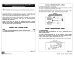
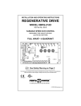
INSTALLATION AND OPERATION MANUAL
MODEL KBPW-240D
KB Part No. 8401 (Black Case) • Part No. 8402 (White Case)
NEMA 4X, IP-65
PWM DC Motor Speed Control For PM and Shunt Wound Motors
Rated 7.5 Amps DC, 11.5 Amps AC @ 115/230 VAC
ON
STOP
OL
PENTA-DRIVE™
PWM DC MOTOR SPEED CONTROL
50
40
60
70
30
20
80
10
90
0
100
%
FWD
BRK
REV
NEMA-4X / IP-65
START
RUN
STOP
JOG
™
!
See Safety Warning on Page 2
The information contained in this manual is intended to be accurate. However, the manufacturer retains the
right to make changes in design which may not be included herein.
TM
A COMPLETE LINE OF MOTOR DRIVES
© 2002 KB Electronics, Inc.
See back cover
TABLE OF CONTENTS
Section
Page
i.
Safety Warning . . . . . . . . . . . . . . . . . . . . . . . . . . . . . . . . . . . . . . . . . . . . . . . . . . . . . . . . . . 1
I.
Introduction . . . . . . . . . . . . . . . . . . . . . . . . . . . . . . . . . . . . . . . . . . . . . . . . . . . . . . . . . . . . . 1
II.
Simplified Operating Instructions . . . . . . . . . . . . . . . . . . . . . . . . . . . . . . . . . . . . . . . . . . . . . 2
III.
Wiring Instructions . . . . . . . . . . . . . . . . . . . . . . . . . . . . . . . . . . . . . . . . . . . . . . . . . . . . . . . . 6
IV.
Setting Selectable Jumpers . . . . . . . . . . . . . . . . . . . . . . . . . . . . . . . . . . . . . . . . . . . . . . . . . 9
V.
Mounting Instructions . . . . . . . . . . . . . . . . . . . . . . . . . . . . . . . . . . . . . . . . . . . . . . . . . . . . 12
VI. Operation . . . . . . . . . . . . . . . . . . . . . . . . . . . . . . . . . . . . . . . . . . . . . . . . . . . . . . . . . . . . . 12
VII. AC Line Fusing . . . . . . . . . . . . . . . . . . . . . . . . . . . . . . . . . . . . . . . . . . . . . . . . . . . . . . . . . 13
VIII. Trimpot Adjustments . . . . . . . . . . . . . . . . . . . . . . . . . . . . . . . . . . . . . . . . . . . . . . . . . . . . . 13
IX. Diagnostic LEDs . . . . . . . . . . . . . . . . . . . . . . . . . . . . . . . . . . . . . . . . . . . . . . . . . . . . . . . . 14
X.
Optional Accessories . . . . . . . . . . . . . . . . . . . . . . . . . . . . . . . . . . . . . . . . . . . . . . . . . . . . . .15
XI. Limited Warranty . . . . . . . . . . . . . . . . . . . . . . . . . . . . . . . . . . . . . . . . . . . . . . . . . . . . . . . . 16
Tables
1.
Electrical Ratings . . . . . . . . . . . . . . . . . . . . . . . . . . . . . . . . . . . . . . . . . . . . . . . . . . . . . . . . 3
2.
General Performance Specifications . . . . . . . . . . . . . . . . . . . . . . . . . . . . . . . . . . . . . . . . . . 3
3.
Terminal Block Wiring Information . . . . . . . . . . . . . . . . . . . . . . . . . . . . . . . . . . . . . . . . . . . . 6
4.
Field Connection (Shunt Wound Motors Only) . . . . . . . . . . . . . . . . . . . . . . . . . . . . . . . . . . . 7
5.
Setting Motor Current (SCR & PWM Motor Horsepower Ratings) . . . . . . . . . . . . . . . . . . . 10
Figures
1.
Control Layout . . . . . . . . . . . . . . . . . . . . . . . . . . . . . . . . . . . . . . . . . . . . . . . . . . . . . . . . . . . 4
2.
Mechanical Specifications . . . . . . . . . . . . . . . . . . . . . . . . . . . . . . . . . . . . . . . . . . . . . . . . . . .5
3.
Power Connection . . . . . . . . . . . . . . . . . . . . . . . . . . . . . . . . . . . . . . . . . . . . . . . . . . . . . . . . 6
4.
Full Voltage Field . . . . . . . . . . . . . . . . . . . . . . . . . . . . . . . . . . . . . . . . . . . . . . . . . . . . . . . . 7
5.
Half Voltage Field . . . . . . . . . . . . . . . . . . . . . . . . . . . . . . . . . . . . . . . . . . . . . . . . . . . . . . . . 7
6.
Remote Potentiometer . . . . . . . . . . . . . . . . . . . . . . . . . . . . . . . . . . . . . . . . . . . . . . . . . . . . 7
7A. Remote 3-Wire Start/Stop Switch with Normally Open Start Contact
and Normally Open Stop Contact . . . . . . . . . . . . . . . . . . . . . . . . . . . . . . . . . . . . . . . . . 8
7B. Remote 3-Wire Start/Stop Switch with Normally Open Start Contact
and Normally Closed Stop Contact . . . . . . . . . . . . . . . . . . . . . . . . . . . . . . . . . . . . . . . . 8
7C. Remote 2-wire Start/Stop Switch with Normally Open Start/Stop Contact . . . . . . . . . . . . . . 8
8.
Start/Stop Function Eliminated (Jumper Installed) . . . . . . . . . . . . . . . . . . . . . . . . . . . . . . . . 8
9.
Voltage Following . . . . . . . . . . . . . . . . . . . . . . . . . . . . . . . . . . . . . . . . . . . . . . . . . . . . . . . . 8
10. Inhibit Circuit . . . . . . . . . . . . . . . . . . . . . . . . . . . . . . . . . . . . . . . . . . . . . . . . . . . . . . . . . . . . 9
11. Enable Connection . . . . . . . . . . . . . . . . . . . . . . . . . . . . . . . . . . . . . . . . . . . . . . . . . . . . . . . 9
12. Enable Circuit Using Potentiometer . . . . . . . . . . . . . . . . . . . . . . . . . . . . . . . . . . . . . . . . . . . 9
13. DC Tach-Generator . . . . . . . . . . . . . . . . . . . . . . . . . . . . . . . . . . . . . . . . . . . . . . . . . . . . . . . 9
14. Motor Voltage Selection (J1) . . . . . . . . . . . . . . . . . . . . . . . . . . . . . . . . . . . . . . . . . . . . . . . 10
15. Motor Current Selection (J2) . . . . . . . . . . . . . . . . . . . . . . . . . . . . . . . . . . . . . . . . . . . . . . . 10
16. Removing Resistor R35 (for low current selection) . . . . . . . . . . . . . . . . . . . . . . . . . . . . . . 10
17. Current Limit Mode Selection (J3) . . . . . . . . . . . . . . . . . . . . . . . . . . . . . . . . . . . . . . . . . . . 11
18. DC Tach-Generator Voltage Selection (J4) . . . . . . . . . . . . . . . . . . . . . . . . . . . . . . . . . . . . 11
19. DC Tach-Generator with Addition of RT . . . . . . . . . . . . . . . . . . . . . . . . . . . . . . . . . . . . . . . 12
ii
20. Run Relay Output Mode Selection (J5) . . . . . . . . . . . . . . . . . . . . . . . . . . . . . . . . . . . . . . . 12
21. Stop Switch Type Selection (J6) . . . . . . . . . . . . . . . . . . . . . . . . . . . . . . . . . . . . . . . . . . . . 12
22. Enable Selection . . . . . . . . . . . . . . . . . . . . . . . . . . . . . . . . . . . . . . . . . . . . . . . . . . . . . . . . 12
23. ACCEL Trimpot Range . . . . . . . . . . . . . . . . . . . . . . . . . . . . . . . . . . . . . . . . . . . . . . . . . . . 13
24. DECEL Trimpot Range . . . . . . . . . . . . . . . . . . . . . . . . . . . . . . . . . . . . . . . . . . . . . . . . . . . 13
25. MAX Trimpot Range . . . . . . . . . . . . . . . . . . . . . . . . . . . . . . . . . . . . . . . . . . . . . . . . . . . . . 13
26. MIN Trimpot Range . . . . . . . . . . . . . . . . . . . . . . . . . . . . . . . . . . . . . . . . . . . . . . . . . . . . . . 13
27. JOG Trimpot Range . . . . . . . . . . . . . . . . . . . . . . . . . . . . . . . . . . . . . . . . . . . . . . . . . . . . . 14
28. CL Trimpot Range . . . . . . . . . . . . . . . . . . . . . . . . . . . . . . . . . . . . . . . . . . . . . . . . . . . . . . . 14
29. TCL Trimpot Range . . . . . . . . . . . . . . . . . . . . . . . . . . . . . . . . . . . . . . . . . . . . . . . . . . . . . . 14
30. IR Trimpot Range . . . . . . . . . . . . . . . . . . . . . . . . . . . . . . . . . . . . . . . . . . . . . . . . . . . . . . . 14
iii
Electrical Hazard Warning Symbol: Failure to observe this warning could result in
electrical shock or electrocution.
!
Operational Hazard Warning Symbol: Failure to observe this warning could result in
serious injury or death.
i.
!
SAFETY WARNING! Please read carefully
This product should be installed and serviced by a qualified technician, electrician, or electrical
maintenance person familiar with its operation and the hazards involved. Proper installation, which
includes wiring, mounting in proper enclosure, fusing or other overcurrent protection, and grounding
can reduce the chance of electrical shocks, fires, or explosion in this product or products used with this
product, such as electric motors, switches, coils, solenoids, and/or relays. Eye protection must be worn
and insulated adjustment tools must be used when working with control under power. This product is
constructed of materials (plastics, metals, carbon, silicon, etc.) which may be a potential hazard.
Proper shielding, grounding, and filtering of this product can reduce the emission of radio frequency
interference (RFI) which may adversely affect sensitive electronic equipment. If further information is
required on this product, contact the factory. It is the responsibility of the equipment manufacturer and
individual installer to supply this Safety Warning to the ultimate end user of this product. (SW effective
11/1992.)
This control contains electronic Start/Stop circuits that can be used to start and stop the control.
However these circuits are never to be used as safety disconnects since they are not fail-safe. Use
only the AC line for this purpose.
Be sure to follow all instructions carefully. Fire and/or electrocution can result due to improper use
of this product.
PWM Safety Warning! This control contains a safety circuit which is designed to prevent
full speed runaway in the event the main power transistor fails. However, this safety circuit is not infallible and may itself fail to operate and therefore allow a full speed runaway condition to exist. The installer of this product should take proper precautions to include other
means to protect the operator or the machine involved (such as mechanical disconnects, warning notices, etc.).
!
This product complies with all CE directives pertinent at the time of manufacture. Contact the
Sales Department for detailed installation and Declaration of Conformity. Installation of a CE
approved RFI filter (KBRF-200A [P/N 9945C] or equivalent) is required. Additional shielded motor cable
and/or AC line cables may be required along with a signal isolator (KBSI-240D [P/N 9431] or equivalent).
I.
INTRODUCTION
Thank you for purchasing the KBPW-240D. KB Electronics, Inc. is committed to providing total
customer satisfaction by producing quality products that are easy to install and operate. The
KBPW-240D is manufactured with surface mount components incorporating advanced circuitry and technology.
The KBPW-240D is a Pulse Width Modulated (PWM) control in a NEMA-4X / IP-65 watertight
and washdown enclosure designed to operate PWM and SCR rated Permanent Magnet and
Shunt Wound motors ranging from 0.2 Amps DC to 7.5 Amps DC. It operates at a switching
frequency greater than 16kHz to provide high motor efficiency and quiet operation. Special circuitry automatically accepts AC line input voltages of 115 Volts AC to 208/230 Volts AC
(±10%, 50/60Hz) without having to make a jumper selection.
Standard panel mounted features include diagnostic LEDs (power on, stop, and overload),
Start/Stop switch, and speed potentiometer. Other features include barrier terminal blocks
(facilitate wiring of AC line, motor armature, motor field, tach-generator and run relay connections), adjustable trimpots (acceleration, deceleration, maximum speed, minimum speed, jog
speed [used with optional Run/Jog switch], current limit, timed current limit and IR Comp.)
1
Optional accessories include On/Off AC Line Switch, FWD-BRK-REV Switch, Run-Stop-Jog
Switch, Signal Isolator, and Anti-Plug Reversing Module. Quick-connect terminals are provided for easy installation of all optional accessories. The control is available in black finish (P/N
8401) and FDA approved white finish (P/N 8402).
STANDARD FEATURES
•
Short Circuit Protection – Protects control from a short circuit at motor connections.
•
Electronic Motor Burnout Protection – Timed Current Limit shuts down the control if a prolonged overload condition exists.
•
Active Bridge – Limits the AC line inrush current when power is turned on and also prevents
high speed runaway if the power transistor shorts.
•
Heat Spreader – Allows power transistor to operate safely during momentary overload conditions.
•
Auto AC Line Select – Control automatically adjusts for 115 or 208/230 Volt AC line input.
•
Start/Stop Switch – Provides electronic start and stop functions.
•
Diagnostic LEDs – For power on (ON), stop (STOP) and motor overload (OL).
•
Trimpots – Provide adjustment for acceleration (ACCEL), deceleration (DECEL), maximum
speed (MAX), minimum speed (MIN), jog speed (JOG), current limit (CL), timed current limit
(TCL), and IR compensation (IR).
•
Selectable Jumpers – Provide settings for armature voltage or tach-generator feedback (J1),
motor current (J2), timed or non-timed current limit (J3), tach-generator voltage (J4), and run
relay output (J5).
•
Barrier Terminal Blocks – Facilitate wiring of AC line, motor armature and field, tach-generato, run relay output, and thermal or enable switch.
•
Quick-Connect Terminals – Facilitate connecting Start/Stop switch, Run-Stop-Jog switch,
FWD-BRK-REV switch, and Inhibit switch.
II.
SIMPLIFIED OPERATING INSTRUCTIONS
IMPORTANT – You must read these simplified operating instructions before proceeding.
These instructions are to be used as a reference only and are not intended to replace the
detailed instructions provided herein. You must read the Safety Warning, on page 1, before
proceeding.
A. Power Connection – Connect the AC line to L1 and L2 terminals of TB1 and the ground
wire (Earth) to the green ground screw as shown in Figure 3, on page 6, and as described
in Section IIIA, on page 6, and Section IIIB, on page 6.
B. Permanent Magnet (PM) Motor Connection (Two-Wire Type) – Connect the motor armature to A1 (+) and A2 (-) terminals of TB1 as shown in Figure 3, on page 6, and as described
in Section IIIC, on page 6. Be sure that jumper J3 is set to the corresponding motor voltage
position as described in Section IVA, on page 10. Do not use F1 and F2 terminals of TB2
for any purpose other than to power the field of a shunt wound motor. Do not use F1
and F2 terminals for PM motors.
Note: Motor performance and efficiency, including brush life, may be adversely affected
when operating the control in stepdown mode (208/230 Volt AC line with 90/130 Volt DC
motors).
C. Shunt Wound Motors (Four-Wire Type) – Connect the motor armature as described in
Section IIIC, on page 6. Connect full voltage field wires (90 Volt DC motors with 100 Volt
DC field and 180 Volt DC motors with 200 Volt DC field) to F1 (+) and F2 (-) terminals of TB2
as described in Section IIID, on page 7. Connect half voltage field wires (90 Volt DC motors
with 50 Volt DC field and 180 Volt DC motors with 100 Volt DC field) to F1 (+) terminal of
TB2 and L1 (-) terminal of TB1 as described in Section IIIE, on page 7.
Note: Do not connect motor armature leads to F1 and F2 terminals.
2
D. Motor Current – Jumper J2 is factory set for 7.5 Amp motors. For lower current motors, set
jumper J2 to the corresponding motor current as described in Section IVB, on page 10.
Note: The factory setting for Current Limit is 150% of the nominal current setting (example:
if jumper J2 is set to “5A” position, the CL trimpot is calibrated for 7.5 Amps).
E. Trimpot Settings – All trimpots have been factory set as shown in Figure 1, on page 4.
Trimpots may be readjusted as described in Section VIII, on page 13.
F. Diagnostic LEDs – After power has been applied, observe the LEDs to verify proper control function as described in Section IX, on page 14.
G. Start/Stop Switch – The control is supplied with a prewired Start/Stop switch as described
in Section IIIG, on page 7. This switch must be used to start the control each time the AC
power is lost or the control shuts down due to TCL. To override this function, see Section
IIIG, on page 7.
TABLE 1 – ELECTRICAL RATINGS
AC Line Voltage
(±10%, 50/60 Hz)
(Volts AC)
Motor Voltage
(Volts DC)
Maximum AC
Line Current
(Amps RMS)
Maximum
Load Current
(Amps DC)
115
0 – 90, 130
11.5
208 – 230
0 – 180, 260
11.5
Maximum Horsepower
HP, (kW)
Field Voltage
(Volts DC)
SCR Rated
Motors
PWM Rated
Motors
7.5
3/4, (0.5)
1, (0.75)
100
7.5
11⁄2, (1)
2, (1.5)
200
TABLE 2 – GENERAL PERFORMANCE SPECIFICATIONS
Parameter
Operating Frequency (kHz)
Factory Setting
>16
–
0 – 50
–
Current Range (High Scale) (Amps DC)
1.7, 2.5, 3.5, 5.0, 7.5
7.5
Current Range (Low Scale) (Amps DC) 1
0.2, 0.3, 0.4, 0.5, 0.8
–
Operating Temperature Range at Full Rating (ºC)
ACCEL and DECEL Range (Seconds)
Jog Speed (% Base Speed)
0.5 – 10
1
0 – 50
15
MIN Speed Range (% Base Speed [90VDC & 180VDC Motors])
0 – 30
0
MAX Speed Range (% Base Speed [90VDC & 180VDC Motors])
50 – 140
100
IR Comp Range at 90 Volts DC Output (∆Volts DC at Full Load)
0 – 15
4
IR Comp Range at 180 Volts DC Output (∆Volts DC at Full Load)
0 – 30
8
CL Range (% Range Setting)
0 – 200
150
0.5 – 10
5
Timed Current Limit (TCL) Range (Seconds)
AC Line Input Voltage (Volts AC, ±10%, 50/60 Hz)
AC Line Regulation (% Base Speed)
Armature Voltage Range at 115 Volts AC Line Input (Volts DC)
Armature Voltage Range at 208/230 Volts AC Line Input (Volts DC)
1.
2.
Specification
115 – 208/230
–
0.5
–
0 – 130
90
0 – 130 2, 0 – 260
90
Armature Feedback Load Regulation (% Base Speed)
1
–
Tach-Generator Feedback Load Regulation (% Set Speed)
1
–
Field Voltage at 115 Volts AC Line Input (Volts DC)
100/50
–
Field Voltage at 208/230 Volts AC Line Input (Volts DC)
200/100
–
Speed Range (Ratio)
50:1
–
Voltage Following Linearity (% Base Speed)
±0.5
–
For low current operation, remove resistor R35 as described in section IVB, on page 10
Step-down operation.
3
FIGURE 1 – CONTROL LAYOUT
(Illustrates Factory Setting of Jumpers and Approximate Trimpot Settings)
To LED Board
ACCEL DECEL MAX
START/STOP SWITCH
MIN
JOG
CL
TCL
IR
KBPW-240D
RED
CON1
BLACK
INH2 INH1
INH2
WHITE
COM
NC
RELAY
JOG
J5
NC NO
TT+
EN2
EN1
J4
J1
T
180V
J2
90V
TACH
K1
EN
J7 ENABLE
P2
P2
P1
TB3
K2
RELAY
P3
P1
MAIN SPEED POTENTIOMETER
NO
STOP
ORANGE
WHITE
STOP
COM START
START J6
P3 JOG STOP
VIOLET
J3
TCL NTCL
INH1
7V 50V
BLU BLU WHT WHT
ORN RED WHT BLK
J7A
J7B
L1A L1B L2A L2B
A1B A1A A2B A2A
CON2
TB1
TB2
F1
ACCEL DECEL MAX
F2
A1
MIN
A2
JOG
L1
L2
CL
TCL
Enlarged view of trimpots
4
IR
H L
AMP
7.5 0.8
5.0 0.5
3.5 0.4
2.5 0.3
1.7 0.2
8.88
225
0.36
9
STOP
OL
FWD
60
0
RUN
JOG
START
STOP
NEMA-4X / IP-65
REV
™
100
10
BRK
80
90
20
%
70
50
30
40
PWM DC MOTOR SPEED CONTROL
PENTA-DRIVE™
ON
9.49
241
5.00
127
CONTROL SHOWN WITH OPTIONAL FWD-BRK-REV AND RUN-STOP-JOG SWITCHES
8.23
209
5.89
150
5.47
139
FIGURE 2 – MECHANICAL SPECIFICATIONS (INCHES / mm)
5
III.
FIGURE 3 – POWER CONNECTION
WIRING INSTRUCTIONS
WARNING! Read Safety
Warning, on page 1, before
using this control. Disconnect the AC
line before wiring.
!
TB1
TB2
F1 F2
A1
A2
L1
L2
Note: To avoid erratic operation, do not
bundle AC line and motor wires with wires
+
from signal following, start/stop switch,
inhibit, or any other signal wires. Use
M
shielded cables on all signal wiring over
12” (30cm). Shield should be Earth
GROUND
AC LINE
MOTOR
grounded on the control side only. Wire
(EARTH)
the control in accordance with the
National Electrical Code requirements
and other codes that may apply to your area. See Figure 3, Table 3 and Table 4, on page 7.
TABLE 3 – TERMINAL BLOCK WIRING INFORMATION
Supply Wire Gauge
(AWG - Cu)
Terminal
Block
Designation
Connections
Minimum
Maximum
Maximum
Tightening Torque
(in-lbs)
TB1
AC Line Input
L1 & L2
22
12
12
TB1
Motor Armature
A1 & A2
22
12
12
TB2
Motor Field (Shunt Wound Motors Only)
F1 & F2
24
14
3.5
TB3
Tach-Generator
T+ & T-
24
14
3.5
TB4
Run Relay
K1 & K2
24
14
3.5
Be sure to properly fuse each conductor that is not at ground potential. Do not fuse neutral
or grounded conductors. See Section VII, on page 13. A separate AC line switch or contactor must be wired as a disconnect so that each ungrounded conductor is opened. An accessory On/Off AC Line Switch (P/N 9341) may be used in lieu of, or in addition to, the Start/Stop
switch. The switch can be wired for single pole or double pole operation, as required.
To maintain the watertight integrity of the control, be sure to use suitable watertight connectors
and wiring which are appropriate for the application. Two 7/8” (22.2mm) knockout holes are
provided for standard 1/2” knockout connectors (not supplied) for wiring. A watertight plug is
provided if only one knockout is required.
Warning! Do not wire switches or relays in series with the armature. Armature switching
can cause catastrophic failure of motor and/or control. To avoid erratic operation, do not
bundle AC line and motor wires with potentiometer wires, voltage following wires, Start/Stop
switch wires, inhibit wires, or any other signal wires. Use shielded cables on all signal wiring
over 12” (30cm) long. Shield should be Earth grounded on the control side only. Warning! Do
not use CON2 for any purpose other than to power the optional Anti-Plug Reversing
Module APRM-PC (P/N 9378A).
!
A. AC Line Connection – Wire AC line input to L1 and L2 terminals of TB1 as shown in
Figure 3.
B. Ground Connection – Earth ground the control chassis using the green ground screw that
is provided on the inside of the control to the right side of TB1 as shown in Figure 3.
C. Permanent Magnet (PM) Motor Connection – Wire the motor armature leads to A1 (+) and
A2 (-) terminals of TB1 as shown in Figure 3. Be sure jumper J1 is set to the appropriate
motor voltage and that J3 is set to the appropriate motor current. For step-down operation
(230 Volt AC line input with 90 Volt DC SCR rated motor or 130 Volt DC PWM rated motor)
set jumper J1 to “90V” position. However, in step-down operation the motor may have
reduced brush life - consult motor manufacturer.
6
Note: Do not connect motor armature
leads to F1 and F2 terminals. Do not
use F1 and F2 terminals for PM motors.
D. Full Voltage Field Connection (Shunt
Wound Motors Only) – Wire the motor
field leads to F1 (+) and F2 (-) terminals
of TB2 as shown in Figure 4 & Table 4.
Note: Do not connect motor armature
leads to F1 and F2 terminals.
FIGURE 4 – FULL VOLTAGE FIELD
TB1
TB2
F1
Note: Do not connect motor armature
leads to F1 and F2 terminals.
Warning! Do not use F1 and F2 terminals of TB2 for any purpose other
than to power the field of a shunt
wound motor.
A2
L1
L2
+
FIELD
M
-
Warning! Do not use F1 and F2 terminals of TB2 for any purpose other
than to power the field of a shunt
wound motor.
E. Half Voltage Field Connection (Shunt
Wound Motors Only) – Wire the motor
field leads to F1 (+) and L1 (-) terminals
of TB2, as shown in Figure 5 & Table 4.
A1
F2
+
GROUND
AC LINE
MOTOR
(EARTH)
FIGURE 5 – HALF VOLTAGE FIELD
TB1
TB2
F1
F2
A1
A2
L1
L2
+
+
FIELD
M
-
MOTOR
GROUND
AC LINE
(EARTH)
TABLE 4 – FIELD CONNECTION (Shunt Wound Motors Only)
AC Line Voltage
(Volts AC)
Armature Voltage
(Volts DC)
Field Voltage
(Volts DC)
Field Connections
115
90 – 130
100
F1 & F2
115
90 – 130
50
F1 & L1
230
180 – 260
200
F1 & F2
230
180 – 260
100
F1 & L1
230
90 – 130
100
F1 & L1
FIGURE 6 – REMOTE POTENTIOMETER
F. Remote Main Speed Potentiometer
Connection – The control is supplied with a
High Side
prewired main speed potentiometer mounted
P3
Wiper
on the front cover. To operate the control
P2
from a remote potentiometer (5kΩ), remove
Low Side
P1
MAIN SPEED
the white, orange, and violet potentiometer
POTENTIOMETER
(FRONT VIEW)
leads from P1, P2, and P3 terminals, respectively. The leads may be taped and left inside
the control. The potentiometer assembly may be removed if a watertight seal is used to
cover the hole in the front cover. Connect the remote main speed potentiometer wires to
terminals P1 (low side), P2 (wiper), and P3 (high side) as shown in Figure 6.
G. Remote Start/Stop Switch Connections – The control is supplied with a prewired
Start/Stop switch mounted on the front cover. To operate the control from a remote
Start/Stop switch (type: (ON)-OFF-ON, SPDT), remove the white, black, and red wires
from START, COM, and STOP terminals, respectively. The leads may be taped and left in
the control. The switch itself may be removed if a watertight seal is used to cover the hole
7
STOP
FIGURE 7A – REMOTE 3-WIRE START/STOP SWITCH
in the front cover. Connect the
WITH NORMALLY OPEN START CONTACT
remote Start/Stop switch wires to
AND NORMALLY OPEN STOP CONTACT
START (momentary), COM
(common), and STOP (constant)
Start
terminals as shown in Figure 7A.
J6
MOMENTARY
START
NO
CONTACT
After applying power, momentariCOM
ly set the Start/Stop switch to
NC
MAINTAINED
“START” position. The motor will
STOP
CONTACT
Stop
operate at the set speed of the
main speed potentiometer. To stop the motor,
FIGURE 7B – REMOTE 3-WIRE START/STOP SWITCH WITH
set the Start/Stop switch
NORMALLY OPEN START CONTACT
to “STOP” position.
AND NORMALLY CLOSED STOP CONTACT
Start
COM
MOMENTARY
NORMALLY CLOSED
CONTACT
For remote 2-wire
Start/Stop Switch with
normally open start/stop contact,
see Figure 7C.
Note: For automatic start when
power is applied, the Start/Stop
function can be bypassed. This
can be accomplished by installing
a jumper (provided with control)
between the START and COM terminals. Jumper J6 must be in the
“NO” position. See Figure 8.
STOP
NO
NC
Stop
FIGURE 7C – REMOTE 2-WIRE START/STOP SWITCH
WITH NORMALLY OPEN START/STOP CONTACT
J6
START
COM
STOP
NO
NC
MAINTAINED
NORMALLY CLOSED CONTACT
(CLOSE TO RUN, OPEN TO STOP)
CAUTION! Eliminating the Start/Stop function using
a jumper will cause the motor to run at the main
speed potentiometer setting when the AC line is applied.
!
J6
START
STOP
MOMENTARY
NORMALLY OPEN
CONTACT
STOP
For remote 3-wire
Start/Stop Switch with
normally open start contact and normally closed
stop contact, see
Figure 7B.
FIGURE 8 –START/STOP
FUNCTION ELIMINATED
(JUMPER INSTALLED)
STOP
H. Run Relay Connection – Normally open (NO) or normalJ6
ly closed (NC) relay output contacts are provided at TB4,
START
NO
which will change state when the Start/Stop switch is set
COM
to “START” position or if the control shuts down and goes
NC
STOP
into STOP mode from TCL. The run relay is used to indicate the state of the control (run or stop). Normally open
or normally closed run relay contact outputs can be selected depending on the position of jumper J5. If norFIGURE 9 – VOLTAGE FOLLOWING
mally open is selected (J5 in “NO” position), the
run relay output contacts will close when the
0 - 10V DC
Start/Stop switch is set to “START” position. If norP3
(ISOLATED)
mally closed is selected (J5 set to “NC” position),
+
P2
the run relay output contacts will open when the
P1
Start/Stop switch is set to “START” position. When
the control shuts down and goes into STOP mode
from TCL, or the Start/Stop switch is set to “STOP”
position, the Run Relay output contacts will return to their normal position.
Note: If relay output contacts are not required for your application, J5 may be in any position.
I. Voltage Following Connection – An isolated 0 - 10 Volt DC analog signal can also be used
to control motor speed. See Figure 9.
8
Note: If an isolated signal voltage is not available, an
optional signal isolator can be installed (KBSI-240D,
P/N 9431). Connect the isolated signal voltage to P2
(+) and P1 (-) terminals. Adjustment of the MIN trimpot may be necessary to achieve a 0 Volt DC output.
FIGURE 10 – INHIBIT CIRCUIT
INHIBIT
(CLOSE TO STOP)
(OPEN TO RUN)
INH1
RELAY
INH2
J. Inhibit Connection – The control is supplied with
inhibit terminals (INH1 and INH2) to connect an Inhibit switch. See Figure 10.
These terminals are used to electronicalFIGURE 11 – ENABLE CONNECTION
ly stop the control. When the Inhibit
switch is closed, the control will coast to
TB3
stop. When the Inhibit switch is
K2
opened, the control will accelerate to the
main speed potentiometer setting.
K1
K. Enable Connection – The Enable is
used to electronically start and stop the
control. When the Enable contact is
closed, the control will accelerate to the
Main Speed Potentiometer setting.
When the Enable contact is opened, the
control will coast to stop. Wire the
Enable contacts to Terminals EN1 and
EN2 of Terminal Block TB3 as shown in
Figure 11. The contacts must be isolated
and Jumper J7 must be removed.
Note: The control can also be started and
stopped with an Enable contact in the
Main Speed Potentiometer circuit. The
Enable function is established by wiring a
switch in series with the violet Main Speed
Potentiometer lead which connects to the
P3 terminal. See Figure 12.
Warning! Do not use Enable as a
safety disconnect. Use only the
AC line for this purpose. The Enable
Circuit is not isolated and is not to be
Earth grounded.
TACH
TT+
EN2
EN1
ENABLE
(CLOSE TO RUN)
(OPEN TO STOP)
EN ENABLE
J7
Warning! Do not use Inhibit as a
safety disconnect. Use only the
AC line for this purpose.
!
Note: Jumper J7 must be
removed for Enable to operate.
FIGURE 12 – ENABLE CIRCUIT
USING POTENTIOMETER
ENABLE
(CLOSE TO RUN)
(OPEN TO STOP)
Violet
P3
Orange
P2
White
P1
Main Speed
Potentiometer
FIGURE 13 – DC TACH-GENERATOR
T+
EN2
EN1
TACH
K1
T-
DC TACH-GENERATOR
G
EN ENABLE
J7
L. DC Tach-Generator Connection – Wire
the tach-generator to T+ (+) and T- (-) terminals of TB4 as shown in Figure 13.
Jumper J1 must be in “T” position. Jumper
J4 must be in “7V” position for 7 Volt per
1000 RPM tach-generators or “50V” position for 50 Volt per 1000 RPM tach-generators. See section IVD on page 11.
TB3
K2
RELAY
!
Note: When using a tach-generator, the IR
trimpot should be set fully counterclockwise.
IV.
SETTING SELECTABLE JUMPERS
The KBPW-240D has customer selectable jumpers which must be set before the control can
be used. See Figure 1, on page 4 for location of jumpers.
9
FIGURE 14 – MOTOR VOLTAGE SELECTION
A. Motor Voltage Selection (J1) – Jumper
J1 is factory set to “90V” position for 90
Volt SCR rated motors (or 130 Volt PWM
rated motors). For 180 Volt SCR rated
motors (or 220 Volt PWM rated motors),
set jumper J1 to “180V” position. See
Figure 14.
Note: If jumper J1 is set to “T”
position, a tach-generator must
be wired to TB3. If a tach-generator is not used, jumper J1 must
be in either “90V” or “180V” position. If jumper J1 is in “T” position
and a tach-generator is not used,
the motor will accelerate to full
speed and the main speed potentiometer will not control speed.
B. Motor Current Selection (J2) –
Jumper J2 is factory set to “7.5A”
position for 7.5 Amp motors.
J1
180V
T
180V
T
90V
90V
FIGURE 15 – MOTOR CURRENT SELECTION
J2 Set for 7.5 Amp Motor
(Factory Setting)
High Scale
Current Range
(Amps DC)
Low Scale
Current Range*
(Amps DC)
7.5
0.8
5.0
0.5
3.5
0.4
2.5
0.3
1.7
0.2
*Note: For low (L) motor current range settings (0.8A, 0.5A, 0.4A,
0.3A and 0.2A), it is necessary to remove resistor R35 by cutting it
out of the circuit as shown in figure 16 on page 10.
FIGURE 16 – REMOVING RESISTOR R35
TO REMOVE RESISTOR R35
CUT THE LEADS HERE
R35
D6
ORG RED WHT BLK L1A L1B
A1B
D20
CON2
J7B
J7A
BLU BLU WHT WHT
L2A
L2B
Q4
J6B
Note: For low (L) motor
current settings (0.8A, 0.5A,
0.4A, 0.3A, and 0.2A), it is
necessary to remove resistor R35. Cut the leads at
the locations shown in
Figure 16.
J1 Set for 180 Volt Motors
J1
J6A
For motors of lower amperage, set Jumper J2 to the
corresponding position for
the motor being used. See
Figure 15 and Table 5.
J1 Set for 90 Volt Motors
(Factory Setting)
A1A
A2B
A2A
Q5
TB1
TB2
F1 F2
A1
A2
L1
L2
WARNING!
Disconnect AC line
before cutting out resistor R35. Use an insulated cutter and wear safety glasses.
!
TABLE 5 – SETTING MOTOR CURRENT (SCR & PWM Motor Horsepower Ratings)
J2 Setting
(Amps DC)
SCR Rated Motor Horsepower
HP, (kW)
PWM Rated Motor Horsepower
HP, (kW)
90 Volts DC Motors
180 Volts DC Motors
130 Volts DC Motors
220Volts DC Motors
7.5
3/4, (0.5)
11⁄2, (1)
1, (0.75)
2, (1.5)
5.0
1/2, (0.37)
1, (0.75)
3/4, (0.5)
11⁄2, (1)
3.5
1/3, (0.25)
3/4, (0.5)
1/2, (0.37)
1, (0.75)
2.5
1/4, (0.18)
1/2, (0.37)
1/3, (0.25)
3/4, (0.5)
1.7
1/6, (0.1)
1/3, (0.25)
1/4, (0.18)
1/2, (0.37)
1/4, (0.18)
0.8*
1/12, (0.06)
1/6, (0.1)
1/8, (0.09)
0.5*
1/20, (0.04)
1/10, (0.08)
1/15, (0.05)
1/6, (0.1)
0.4*
1/25, (0.03)
1/12, (0.06)
1/20, (0.04)
1/8, (0.09)
0.3*
1/30, (0.02)
1/15, (0.05)
1/25, (0.03)
1/10, (0.08)
0.2*
1/50, (0.01)
1/25, (0.03)
1/30, (0.02)
1/20, (0.04)
*Note: For low (L) motor current range settings (0.8A, 0.5A, 0.4A, 0.3A and 0.2A), it is necessary to remove resistor R35 as
shown in figure 16.
10
C. Timed and Non-Timed Current Limit
Selection (J3) – Jumper J3 is factory set
to “TCL” position for timed current limiting
operation. See Figure 17. For non-timed
current limiting operation, set jumper J3
to “NTCL” position.
FIGURE 17 – CURRENT LIMIT
MODE SELECTION
J3 Set for TCL Mode
(Timed Current Limit)
(Factory Setting)
J3 Set for NTCL Mode
(Non-Timed Current Limit)
J3
J3
TCL (Timed Current Limit) – When
Jumper J3 is in the “TCL” position, the
control will go into “STOP” after it is in
overload for a predetermined amount of
time (set by the TCL trimpot).
TCL NTCL
TCL NTCL
Resetting the Control After TCL – To reset the control after it has gone into TCL, momentarily set the Start/Stop switch to “START” position or disconnect and reconnect the AC line.
If an On/Off AC Line Switch is installed, set it to “OFF” position and then back to “ON” position. If the Start switch is jumpered (START and COM terminals connected), the control
must be restarted by disconnecting and reconnecting the AC line.
NTCL (Non-Timed Current Limit) – When jumper J3 is set to “NTCL” position, the control
will not go into “STOP” after it is in overload.
Note: TCL trimpot will have no affect when jumper J3 is in “NTCL” position.
D. DC Tach-Generator Voltage Selection (J1 and J4) – For a tach-generator wired to TB3,
set jumper J1 to “T” position. See Figure 18. Jumper J4 is factory set to “7V” position for 7
Volt per 1000 RPM tach-generators wired to TB3. For a 50 Volt per 1000 RPM tach-generator, set jumper J4 to “50V” position.
FIGURE 18 – DC TACH-GENERATOR VOLTAGE SELECTION
Jumper J1 Settings
J1 Set for 90 Volt Motors
(Factory Setting)
J1 Set for
Tach-Generator Input
J1
J1
180V
T
90V
Jumper J4 Settings
J4 Set for 7V per 1000RPM
Tach-Generator Input
(Factory Setting)
J4 Set for 50V per 1000RPM
Tach-Generator Input
J4
J4
7V 50V
7V 50V
180V
T
90V
Note: When using a tach-generator, the IR trimpot should be set fully counterclockwise.
Note: The tach-generator input is designed for 7 Volt or 50 Volt per 1000 RPM tach-generators used with 1800 RPM motors. For tach-generators other than 7 Volt or 50 Volt per
1000 RPM or for motors other than 1800 RPM, an external 1/2 watt resistor (RT) must be
used. Install RT in series with the tach-generator as shown in Figure 19, on page 12.
Jumper J4 must be set to “7V” position.
The value of RT in Ω can be calculated using the following formula:
RT = (1.46 x VT x S) - 19,000
Where VT is the tach-generator voltage (in Volts per 1000 RPM) and S is the base speed of
the motor (in RPM).
Suppose you have a 20 Volt per 1000 RPM tach-generator with a 3600 RPM motor:
RT = (1.46 X 20 X 3600) - 19000 = 86120Ω.
Example:
Choose the closest 1/2W resistor value, which is 82000Ω (82kΩ) or 91000Ω (91kΩ).
Readjustment of the MAX trimpot may be necessary to achieve the desired maximum
output voltage.
11
FIGURE 19 – DC TACH-GENERATOR
WITH ADDITION OF RT
F. Stop Switch Type Selection (J6) –
Jumper J6 is factory set to the “NO” position
for a normally open stop switch, as used on
the front cover. If a remote normally closed
stop switch is used, set Jumper J6 to the
“NC” position. If a remote normally open
stop switch is used, set Jumper J6 to the
“NO” position. See Figure 21.
K1
T+
EN2
EN1
J5 Set for Normally Closed
(NC) Output Contacts
J5
J5
NC NO
NC NO
FIGURE 21 – STOP SWITCH
TYPE SELECTION
J6 Set for
Normally Open Stop Switch
(Factory Setting)
J6
STOP
NO
NC
NO
NC
FIGURE 22 – STOP SWITCH
TYPE SELECTION
J7 Installed to
Enable the Control
(Factory Setting)
J7 Removed to
Connect Enable Contacts
EN
J7
The KBPW-240D is designed with a hinged
case so that when the front cover is open,
all wiring stays intact. To open the cover, the four
screws must be loosened so they are no longer
engaged in the case bottom. After mounting and
wiring, close the cover and make sure that wires will
not get caught or crimped as the cover is closed.
Tighten all four cover screws so that the gasket is
slightly compressed. Do not over tighten.
J6 Set for
Normally Closed Stop Switch
J6
EN
J7
It is recommended that the control be mounted vertically on a flat surface with adequate
ventilation. Leave enough room below the
control to allow for AC line, motor connections, and any other wiring. Although the
control is designed for outdoor and washdown use, care should be taken to avoid
extreme hazardous locations where physical damage can occur. If the control is
mounted in a closed, unventilated location,
allow enough room for proper heat dissipation. If operating the control at full rating, a
minimum enclosure size of 12”W x 24”H x
12”D is required. See Figure 2, on page 5.
RT
J5 Set for Normally Open
(NO) Output Contacts
(Factory Setting)
STOP
!
G
FIGURE 20 – RUN RELAY OUTPUT
MODE SELECTION
MOUNTING INSTRUCTIONS
Warning! The KBPW-240D is not
designed to be used in an explosion-proof application.
DC TACH-GENERATOR
TACH
T-
G. Enable Selection (J7) – Jumper J7 is factory installed to enable the control. If connecting Enable contacts to Terminals EN1
and EN2 of Terminal Block TB3, remove
Jumper J7. See Figure 22.
V.
RELAY
TB3
K2
EN ENABLE
J7
E. Run Relay Output Mode Selection (J5)
– Jumper J5 is factory set to “NO” position
for normally open relay output at TB4. For
normally closed relay output, set jumper
J5 to “NC” position. See Figure 20.
VI. OPERATION
Caution! It is recommended that the bus capacitors
be reconditioned if this product has been in storage for over one year. To recondition the capacitors, apply the AC line, with the drive in Stop Mode, for a minimum of one hour.
After the control has been properly set up (jumpers set to desired positions and wiring completed), the startup procedure can begin. If AC power has been properly brought to the control, the ON and STOP LEDs will be illuminated. Before starting, be sure the main speed
12
potentiometer is fully counterclockwise. To start the control, momentarily set the Start/Stop
switch to “START” position and release it. The STOP LED should no longer illuminate. The
motor should begin to rotate, as the main speed potentiometer is rotated clockwise.
Note: If the motor rotates in the incorrect direction, it will be necessary to disconnect the AC
line, reverse the motor leads, and repeat the startup procedure.
VII. AC LINE FUSING
This control does not contain AC line fuses. Most electrical codes require that each ungrounded conductor contain circuit protection. Installation of a 20 Amp fuse or circuit breaker in series
with each ungrounded conductor is recommended. Check all electrical codes that apply to the
application.
VIII. TRIMPOT ADJUSTMENTS
The KBPW-240D contains trimpots, which are factory set for most
applications. The trimpots are shown in the approximate calibrated positions. Some applications may require readjustment of the
trimpots in order to tailor the control for a specific requirement.
Readjust trimpots as described below.
Warning! If possible, do not adjust trimpots with
main power applied. If adjustments are made with
main power applied, an insulated adjustment tool must be
used and safety glasses must be worn. High voltage exists in
this control. Fire and/or electrocution can result if caution is
not exercised. Safety Warning, on page 1, must be read and
understood before proceeding.
!
A. Acceleration (ACCEL) – Sets the amount of time for the
motor to accelerate from minimum speed to maximum speed.
The ACCEL trimpot is factory set for one (1) second, as
shown in Figure 23. For more rapid acceleration time, rotate
the trimpot counterclockwise. For longer acceleration time,
rotate the trimpot clockwise.
Note: Rapid acceleration settings may cause the current limit
circuit to activate, which will extend the acceleration time.
B. Deceleration (DECEL) – Sets the amount of time for the
motor to decelerate from maximum speed to minimum speed.
The DECEL trimpot is factory set for one (1) second, as
shown in Figure 24. For more rapid deceleration time, rotate
the trimpot counterclockwise. For longer deceleration time,
rotate the trimpot clockwise.
FIGURE 23 – ACCEL
TRIMPOT RANGE
5
1
0.5
FIGURE 24 – DECEL
TRIMPOT RANGE
5
1
0.5
D. Minimum Speed (MIN) – Sets minimum speed of the motor.
The MIN trimpot is factory set for 0% speed, as shown in
Figure 26. For a higher minimum speed setting, rotate the
trimpot clockwise
10
Seconds
FIGURE 25 – MAX
TRIMPOT RANGE
95
100
50
140
% Base Speed
Note: Deceleration time will not be shorter than the maximum
coast time of the motor under actual load.
C. Maximum Speed (MAX) – Sets maximum speed of the
motor. The MAX trimpot is factory set for 100% of base motor
speed, as shown in Figure 25. For a higher maximum speed
setting, rotate the trimpot clockwise. For a lower maximum
speed setting, rotate the trimpot counterclockwise.
10
Seconds
FIGURE 26 – MIN
TRIMPOT RANGE
15
0
30
% Base Speed
13
E. Jog Speed (JOG) – Sets “jog” speed of the motor. The JOG
trimpot is factory set for 15% of motor base speed, as shown
in Figure 27 . For a higher jog setting, rotate the trimpot
clockwise. For a lower jog setting, rotate the trimpot counterclockwise.
Note: The Jog feature requires installation of the Run-Stop-Jog
Switch assembly (P/N 9340).
F. Current Limit (CL) – Sets current limit (overload), which limits
the maximum current to the motor. The current limit set point is
established by the setting of jumper J2 and the setting of the CL
trimpot. The CL trimpot is factory set for 150% of J2 range setting, as shown in Figure 28. For a higher current limit setting,
rotate the trimpot clockwise. For a lower current limit setting,
rotate the trimpot counterclockwise. Two modes of current limiting operation are provided: Non-Timed Current Limit (NTCL)
and Timed Current Limit (TCL). See Section IVC, on page 11.
CAUTION! Adjusting the CL above 150% of motor rating can
cause overheating and demagnetization of some PM motors.
Consult the motor manufacturer. Do not leave the motor in a
locked condition for more than a few seconds since armature
damage may occur.
G. Timed Current Limit (TCL) – Sets the time for the control to
shut down after being in current limit (provides electronic motor
overload protection). The TCL trimpot is factory set for 5 seconds, as shown in Figue 29. For increased TCL time, rotate the
trimpot clockwise. For decreased TCL time, rotate the trimpot
counterclockwise. If the control remains in CL for a predetermined amount of time (set by the TCL trimpot and if jumper J3
is in the “TCL” position), the control will shut down. To reset the
control after it has shut down, momentarily set the start/stop
switch to the “START” position or disconnect and then reconnect the AC line.
!
Warning! When the control shuts down in TCL, the
AC line voltage is still present in the control.
H. Non-Timed Current Limit (NTCL) – When jumper J3 is set to
“NTCL” position and an overload condition exists, the control
will remain in current limit and will not shut down.
FIGURE 27 – JOG
TRIMPOT RANGE
25
15
0
50
% Base Speed
FIGURE 28 – CL
TRIMPOT RANGE
100
150
0
200
% Range Setting
FIGURE 29 – TCL
TRIMPOT RANGE
5
0.5
10
Seconds
FIGURE 30 – IR
TRIMPOT RANGE
7.5, 15
4, 8
I. IR Compensation (IR) – Sets the amount of compensating
0
15, 30
voltage required to keep the motor speed constant under
Volts
changing loads. The IR trimpot is factory set for 4 Volts (for
90 Volt DC output) and 8 Volts (for 180 Volt DC output), as
shwon in Figue 30. For higher compensating voltage, rotate the trimpot clockwise. For
lower compensating voltage, rotate the trimpot counterclockwise.
Note: If the IR compensation is set too high, unstable (oscillatory) operation will result. If
the control is used with a tach-generator, the IR trimpot should be set fully counterclockwise.
IX. DIAGNOSTIC LEDs
The KBPW-240D is designed with LEDs mounted on the front cover to display the control’s
operational status.
A. Power On (ON) – The ON LED will illuminate green when the AC line is applied to the
control.
Note: When removing power to the control, the POWER LED will remain illuminated for a
few seconds until the DC bus voltage discharges.
14
B. Stop (STOP) – The STOP LED will illuminate yellow when the Start/Stop switch is set to
“STOP” position. When AC line is applied, this LED will also be illuminated until the
Start/Stop switch is set to “START” position.
C. Overload (OL) – The OL LED will illuminate red when the control goes into current limit, indicating that the current limit set point has been reached (set by the CL trimpot and the position of jumper J2). This LED will remain illuminated if the control times out in TCL (jumper
J3 set to “TCL” position). The control can be reset by either setting the start/stop switch to
“START” position or by disconnecting and reconnecting the AC line. If the overload condition still exists when the control is restarted or AC line reapplied, the OL LED will illuminate
again. If the OL LED remains illuminated during control operation, a fault condition may
exist. Possible causes for this condition are as follows:
• Motor is overloaded. Check motor current. If the motor is a shunt wound type, the field
may be open or not receiving proper voltage.
• Motor may be defective. Check motor for shorts or grounds.
• CL may be set too low. Check position of CL trimpot and setting of jumper J2.
Note: In some applications, especially those requiring the motor to cycle on and off,
or from one speed to another, or from stop to high speeds, the OL LED may blink,
indicating a transient overload. This may be a normal condition for the application.
X.
OPTIONAL ACCESSORIES
Complete instructions and connection diagrams are supplied with all accessories to facilitate
installation.
A. On/Off AC Line Switch (P/N 9341) – Disconnects the AC line. Mounts on the enclosure
cover and is supplied with a switch seal to maintain watertight integrity.
B. FWD-BRK-REV Switch (P/N 9339) – Provides motor reversing and dynamic braking. This
switch is equipped with a center off hesitation mechanism, which assures that the motor is
fully stopped before it can be reversed. Mounts on the enclosure cover and is supplied with
a switch seal to maintain watertight integrity.
C. Run-Stop-Jog Switch (P/N 9340) – Selects speed setting from either main potentiometer
or JOG trimpot. Mounts on the enclosure cover and is supplied with a switch seal to maintain watertight integrity.
D. Signal Isolator KBSI-240D (P/N 9431) – Provides isolation from non-isolated signal
sources. Mounts on the inside of the enclosure cover.
E. Auto/Manual Switch (P/N 9377) – When used with the KBSI-240D (P/N 9431), it selects
either an isolated signal from the KBSI-240D or from the main speed potentiometer. Mounts
on the enclosure cover and is supplied with a switch seal to maintain watertight integrity.
F. Anti-Plug Reversing Module APRM-PC (P/N 9378A) – Provides electronic braking and
reversing. Mounts on the inside of the enclosure cover.
Note: For use with this control, the APRM-PC must be Revision A or newer.
G. RFI Filters and Chokes – RFI Filters and Chokes are available to provide suppression for
conducted radio frequency interference (RFI). They comply with the CE Directive
89/336/EEC relating to the EMC Class A Industrial Standard and Class B Residential
Standard. See RFI Filters and Chokes Selection Guide (Publication No. D-321).
15
– NOTES –
16
XI. LIMITED WARRANTY
For a period of 18 months from the date of original purchase, KB Electronics, Inc. will repair or
replace, without charge, devices which our examination proves to be defective in material or
workmanship. This warranty is valid if the unit has not been tampered with by unauthorized persons, misused, abused, or improperly installed and has been used in accordance with the
instructions and/or ratings supplied. The foregoing is in lieu of any other warranty or guarantee,
expressed or implied. KB Electronics, Inc. is not responsible for any expense, including installation and removal, inconvenience, or consequential damage, including injury to any person,
caused by items of our manufacture or sale. Some states do not allow certain exclusions or limitations found in this warranty and therefore they may not apply to you. In any event, the total
liability of KB Electronics, Inc., under any circumstance, shall not exceed the full purchase price
of this product. (rev 2/2000)
Copyright © 2002 by KB Electronics, Inc.
All rights reserved. In accordance with the United States Copyright Act of 1976, no part of this
publication may be reproduced in any form or by any means without permission in writing from
KB Electronics, Inc. (8/22/02)
KB Electronics, Inc.
12095 NW 39th Street, Coral Springs, FL 33065-2516 • (954) 346-4900 • Fax (954) 346-3377
Outside Florida Call TOLL FREE (800) 221-6570 • E-mail – [email protected]
www.kbelectronics.com
(A40360) – Rev. B – 8/2002