1
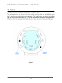
THE OBSERVATORIES OF THE CARNEGIE INSTITUTION OF WASHINGTON LAS CAMPANAS OBSERVATORY Colina El Pino s/n Casilla 601 La Serena, Chile Phone: 56-51-207301 • Fax: 56-51-207308 DOME CONTROL SYSTEM SOFTWARE User Manual Document Code 01- 00-K5 Type User Manual Author Silvia Baeza / Jose M. Soto Date February 15, 2008 Revision Jose M. Soto Revisions Table Date Description February 15, 2008 Document Update July 7, 2005 Document Update November 24, 2004 Added new commands, added new communication features April 25, 2003 Document update Original draft by Steve Shectman ii Table of Contents 1 OVERVIEW OF THE DOME CONTROL SYSTEM..................................................................................1 1.1 General Configuration.......................................................................................................................1 1.2 Devices..............................................................................................................................................2 1.3 Positions............................................................................................................................................3 2 DOME CONTROL SYSTEM INTERFACE...............................................................................................4 2.1 Input Interface / Log Display..............................................................................................................4 2.2 Dome Rotation Display......................................................................................................................5 2.3 Louver Control Display......................................................................................................................6 2.4 Miscellaneous Functions Display.....................................................................................................7 3 COMMANDS SUMMARY........................................................................................................................8 3.1 Dome Command Syntax...................................................................................................................8 3.2 Dome Commands.............................................................................................................................9 3.3 Louver Commands............................................................................................................................9 3.4 Message Commands......................................................................................................................10 3.5 Display Commands.........................................................................................................................10 3.6 Engineering Commands..................................................................................................................11 3.7 Other Commands............................................................................................................................11 4 DOME CONFIGURATION.....................................................................................................................12 4.1 DMCTL.INI File at Magellan I (Baade)............................................................................................12 4.2 DMCTL.INI FiIe at Magellan II (Clay)..............................................................................................13 4.3 DMCTL.INI Description...................................................................................................................13 5 CONTROL SYSTEM SERIAL COMMUNICATION STANDARDS........................................................15 5.1 Command Description.....................................................................................................................16 5.1.1 2: Query Next EDS Message...................................................................................................16 5.1.2 3: Repeat Last EDS Message.................................................................................................17 5.1.3 4: Set UT..................................................................................................................................18 5.1.4 9: Free-form Command...........................................................................................................18 5.2 TCS and Dome control software Communication Links..................................................................19 5.2.1 8: Telescope Elevation Information.........................................................................................19 5.2.2 5: Dome Position ....................................................................................................................19 5.2.3 1: Louver commands...............................................................................................................20 5.3 Communication Protocol between PLC and Dome Control Software.............................................21 6 LOG MESSAGE SYSTEM.....................................................................................................................23 6.1 EDS Log Messages.........................................................................................................................23 6.2 Error Messages...............................................................................................................................26 6.3 Success...........................................................................................................................................28 7 DOME CONTROL SYSTEM DIFFERENCES BETWEEN MAGELLAN I AND II..................................29 8 TROUBLESHOOTING...........................................................................................................................30 APPENDIX A............................................................................................................................................31 APPENDIX B............................................................................................................................................36 APPENDIX C............................................................................................................................................41 iii D O M E C O N T R O L S Y S T E M S O F T W A R E U S E R 1 Overview of the Dome Control System M A N U A L Overview 1 1.1 General Configuration The Dome System is composed of several mechanical and electrical devices attached to the telescope protecting enclosure. This structure is divided in two: the fixed part, which remains static respect to the telescope; and the rotating portion, which turns according to the telescope azimuth positioning requirements. The moving dome is driven by four AC motors controlled by high power electronic controllers, located at the telescope equipment room. A barcode reader senses the dome position, reading a tape installed along the entire dome periphery. There are 20 louvers on the rotating part of the dome, numbered in pairs from 0 to 9, their function is to allow the air circulate freely across the enclosure, keeping a thermal equilibrium between the telescope structure and the ambient. Also, to let the light in, the dome has huge shutter sliding doors and to avoid wind disturbances or moon interference, the wind screen and moon screen could be extended. Finally, attached to the dome is the crane used for instrument changes or any heavy items lifting. To control all these devices located at the rotating dome, a PLC is used along with a couple of power line modems that pass the communication signal down to the control computer through the dome slip rings. In the fixed part, the Dome System groups 8 louvers, numbered individually from 0 to 7, the floor lift which is an elevator to carry things to/from the telescope level, and the hatch which is a cover on the telescope floor that gives access to a lower level. A PLC monitors and controls here too, but the serial communications reach directly the Dome computer. Controlling all of this hardware is the function of the software explained in this manual. Some of the tasks the software is required to perform, are: • Accept high level commands (both locally at the keyboard and remotely from higher level computer systems) to rotate the dome according with telescope azimuth position, and convert them to low level commands for the various motor drives. • Report the dome position together with the motor drives ratings (both on the local display and to higher level computer systems). 1 D O M E C O N T R O L S Y S T E M S O F T W A R E U S E R M A N U A L • Monitor and command louvers opening. • Extend or retract the wind/moon screen and report their status. • Report floor lift, crane, hatch status. • Operate dome high lights. 1.2 Devices There are a number of devices attached to the Dome Control Computer, which executes the DMCTL.EXP program: • Upper Dome Programmable Logic Controller (UPLC): The UPLC is installed in the upper part of the dome, and its main function is to control the opening of 10 pairs of rotating louvers, sensing each motion status and position. It also controls the shutter doors, the wind/moon screen, the high lights and senses the status of the crane. The UPLC serial communication link is routed using an upper Power Line Modem (PLM) through the dome sliding contacts to a lower PLM which is directly attached to COM1 (3F8H) at the Dome computer. • Lower Dome Programmable Logic Controller (LPLC): The LPLC is located in the fixed part of the dome and controls the opening of 8 louvers, sensing their motion status and position. It also senses the floor hatch and lift status. The LPLC serial communication link is directly attached to COM2 (2F8H) at the Dome computer. • Baldor Motor Drives: These are four electronic controllers, each for an AC dome motor, and collectively, they take care of the dome motion. These motor controllers talk serially through four different RS-485 lines attached to a single serial card inside the Dome computer. • Host Computer: The Dome computer takes commands on where to position the dome, and reports on the dome’ s current location. The dome computer is attached via a RS-232 connection on COM3 (3E8) to the higher level host computer (TCS, the Telescope Control System). The Dome computer prompt character, address character, and response character on this communications line is set internally in the code. • Bar-Code reader. The dome position encoder is an optical bar-coded reader. It is wired directly to the COM4 (2E8) in the Dome computer. 2 D O M E C O N T R O L S Y S T E M S O F T W A R E U S E R M A N U A L 1.3 Positions The dome structure showing louver positions is shown in Fig. 1. The rotating louvers are drawn in the inner circle; note that they are controlled in pairs, that’ s why they are numbered in the same way. The fixed louvers are part of the building and are drawn in the outer part of Fig. 1. The box at the bottom represents the control room. All louvers have four opening states: fully closed, ¼ open, ½ open, ¾ open and fully open. Figure 1 3 D O M E C O N T R O L S Y S T E M S O F T W A R E U S E R M A N U A L Interface 2 2 Dome Control System Interface To start the DOME program, push the reset button (the black rocker switch just below the red power switch) on the computer. The program will load automatically from the flash disk. Resetting the computer assures that the system will start each time in the proper state. When the program is loaded, you should see the usual video display of the dome control program. The different portions of the control screen are described below. 2.1 Input Interface / Log Display Once the program has been started, you can type commands, which appear at the "*" prompt in the input panel. At the top of the input panel, the average and maximum cycle times for the program status loop are displayed in milliseconds. Status messages are displayed in the system message box. The UT at which the message occurred is followed by a three-digit message identification code. A red LED indicates that the message describes an error. A green LED indicates that the message describes a normal condition. Most of the errors are caused by serial communications errors, or by some piece of remote equipment being turned off. A certain number of errors may occur when the program is loaded, before the serial communications are properly initialized. A few errors will occur during normal operation. The messages are numbered from 0 to 999. When the message buffer is full, new messages are written over the old ones starting from the beginning (so message 1000 is written to location 0 and so on). The most recent message is displayed in white. You can scroll back and forth through the message buffer using the appropriate keys. To return to the page with the most recent message, be sure to type <End>, or else new messages will not be displayed on the screen (although new messages will always be written to the message buffer). The elapsed time, in days, that the program has been running is shown in the "et" entry, and the current UT is shown as well. The UT is set by the CMOS clock in the CPU when the program starts, but is updated by the TCS computer as soon as communication is established, and afterwards once per hour. 4 D O M E C O N T R O L S Y S T E M S O F T W A R E U S E R M A N U A L 2.2 Dome Rotation Display The top panel on the screen is the dome rotation display. The dome encoder is a bar-code reader. The bar-code reader is turned off when the keyswitch on the dome drive and stow pin control box (in the dome) is set to the "off" position. Because the lifetime of the bar-code reader is only about 10,000 hours, please be sure to turn the keyswitch "off" when the telescope is not in use. Turn the keyswitch to "remote" in order to enable computer control of the dome rotation. If the bar-code reader is not working, or is turned off, a red LED will be displayed next to the azimuth reading. If the bar-code reader is working properly, and a code is being detected, the LED will be green. If the bar-code reader is between two codes (this happens about 25% of the time) the LED will be black. The dome azimuth is 0° when the dome is pointed north, and 90° when the dome is pointed east. The left-hand graph shows the dome rotation velocity. The dome accelerates to full speed in 10 seconds, and decelerates from full speed in 10 seconds (full speed is currently set to 1.78° /s). For short moves the dome will never reach full speed and the velocity profile will be a triangle. For a long move the dome will move at full speed for some of the time, and the velocity profile will be a trapezoid. Numerical values for the velocity and for the scale of the display are shown to the left of the graph, in white. There are 4 dome-drive motors. The right-hand graph shows the current in each of the motors. If the motors are turned off, the values will be zero. When the motors are turned on, the baseline current will be 3 amps, and will increase above 3 amps when torque is required to turn the dome. The current in each of the motors should be similar. If each motor is working, 4 green LED's will be displayed to the left of the graph. A fault condition in one of the motors will cause the corresponding LED to turn red. If one of the motors is not working and has been disconnected from its drive wheel, then status checking for that motor can be disabled by typing the command "BALD n 0" (for motor n; the motors are made by Baldor). When status checking for a motor has been disabled, the corresponding LED will turn black. In order to move the dome to a particular azimuth, type the command "DOME n" where n is the desired azimuth angle. If the program has just been started, but the bar-code reader is between codes, the dome will make a small jog in order to scan a nearby bar-code and find out where it is. Then the dome will take off for the desired azimuth. The dome is commanded to move for a certain length of time, and the bar-code reader is only checked when the dome has come to a stop. There is some variation in how far the dome will actually go during a given move, and if the dome is not close enough, one or two additional moves will occur to correct the final azimuth. The dome rotation motion can be stopped in the middle of a move by typing <Esc>. If a serious problem occurs with the dome rotation control logic, it is possible for the dome to stop responding to commands, or even to be stuck in an indefinitely long move. If this happens, DO NOT switch the keyswitch to off, because the dome will come to a screeching halt. Instead, cycle the power to the lower PLC. This will cause the dome to come to a controlled stop, and will also reset the dome control logic. 5 D O M E C O N T R O L S Y S T E M S O F T W A R E U S E R M A N U A L 2.3 Louver Control Display The largest panel on the screen is the louver control display. The louvers are actually controlled by two PLC's (programmable logic controllers). The upper PLC (UPLC) controls all functions on the rotating part of the dome. The lower PLC (LPLC) controls the louvers on the fixed part of the dome, as well as the dome rotation drives. If the PLC’ s are functioning properly, then the corresponding LED on the display will be green. If there is a problem with a PLC, then the corresponding LED will be red. Data is alternately read from and written to each PLC. When a read or write cycle has been completed successfully, the corresponding "R" or "W" flag turns green. There are 20 louvers on the rotating part of the dome, numbered in pairs from 0 to 9. There are 8 louvers on the fixed part of the dome, numbered individually from 0 to 7. The TCS display includes a graphical representation of the louver system which can be used to identify the actual location of each louver. Each pair of louvers on the rotating part of the dome, or individual louver on the fixed part of the dome, can be commanded to open from 0/4 to 4/4 of the full-open position. When the program is first started, there are no command values, and "-/4" is displayed instead. In this case, the louvers will be left in their current positions. The position of each louver is sensed by a potentiometer. The output of the potentiometer, scaled to fit in the range from 0 to 999, is displayed for each louver in the "Val" column. The requested potentiometer reading for each louver is displayed in the "Req" column. The gain and zero point for each potentiometer have been adjusted so that openings 0/4, 1/4, 2/4, 3/4, and 4/4 correspond to values of 100, 200, 300, 400, and 500, respectively. If a louver has been switched to remote mode and is operating properly, a green LED will appear in the "E" column. If an error occurs, the LED will turn red. If the louver is not in remote mode, the LED will be black. Once an error occurs, the louver will not operate until it is reset, by turning the keyswitch on the appropriate louver control box in the dome from "remote" to "off", and then back to "remote." When the motor for a particular louver is energized, the corresponding symbol in the "M" column will change to an up or down arrow, displayed in green. When the open or closed limit switch for a particular louver has been encountered, the corresponding symbol in the "L" column will change to an up or down arrow, displayed in green. If there is an error reading the limit switches, the symbol will turn red. Note that if power to even one of the louver control boxes has been turned off, the PLC will be unable to read the status of any of the louvers, and all of the limit symbols will turn red. The closed limit switch for each louver has been adjusted so that it is encountered at about the value 105, and the open limit switch for each louver has been adjusted so that it is encountered near the value 495. Normally, when a louver is commanded to go to an opening of 0/4 or 4/4, the louver should stop near the value 105 or 495, and the corresponding limit switch symbol should turn green. If the louver travels all the way to 100 or 500, and the display indicates that no limit switch has been encountered, then the corresponding limit switch is probably broken. 6 D O M E C O N T R O L S Y S T E M S O F T W A R E U S E R M A N U A L 2.4 Miscellaneous Functions Display Next to the louver control display is the miscellaneous functions display. If the shutter door control box has been switched to remote mode, the "L" and "R" LED's will turn green. There are two open and two closed limit switches for each shutter door. If both limit switches in a pair are engaged, the corresponding "OPN" or "CLS" indicator will turn green. If only one switch is engaged, the indicator will turn red. In this case one of the limit switches in the pair is broken and should be repaired immediately. The shutter doors normally take about 100 seconds to open or close. The program allows 120 seconds to elapse before a limit switch is encountered. If more than 120 seconds is required, the shutter doors will stop and an error message will be displayed. The shutter doors can be stopped at an intermediate position by typing <Esc>. Commands to the moonscreen or windscreen are entered as a percent of full extension, from 0 (completely retracted) to 99 (completely extended). When the program is first started, there are no command values, and "--" is displayed instead. In this case, the moonscreen or windscreen will be left in its current position. The moonscreen and windscreen encoder values, scaled to fit in the range from 0 to 999, are displayed in the "Val" column. If there is an encoder error, this value will be displayed in red. The requested value for each encoder is displayed in the "Req" column. If the moonscreen and windscreen control box has been switched to remote mode, the LED's in the "E" column will turn green. If a control error occurs, the corresponding LED will turn red. If the moonscreen motor or the windscreen motor is energized, the corresponding arrow in the "M" column will be displayed in green. If the either the moonscreen or the windscreen has reached an open or closed limit, the corresponding arrow in the "L" column will be displayed in green. The moonscreen and windscreen closed limits should normally be encountered at about the value 1/99, and the open limits at about the value 98/99. If a command of 0 or 99 is entered, motion should stop just short of the requested encoder reading, and the corresponding limit switch indicator should turn green. If the motion continues all the way to the requested value, and there is no indication that a limit switch has been encountered, then the corresponding limit switch is broken and should be repaired immediately. 7 D O M E C O N T R O L S Y S T E M S O F T W A R E U S E R M A N U A L Commands 3 3 Commands Summary 3.1 Dome Command Syntax All DOME commands begin with a command code of up to four letters, followed by up to two numeric arguments. The numeric arguments (if there are more than one) are separated by spaces; spaces are permitted but not required between the command and the first numeric argument. Letters may be upper or lower case. The numeric arguments may include a decimal point. For example, the commands dome47.2 DOME 47.20 will both rotate the dome to position angle 47.2 degrees. The backspace key moves the cursor back one character at time. All commands are terminated by a <cr>. During normal operation, the host computer communicates with the Dome computer via COM 3: (the serial port). The host computer will typically use the EDS (Engineering Data Stream) log entries to check for errors and get the system’ s current status. It will then use the move commands to update the dome position. The ESC key can be used to attempt to stop the most important moving parts in case any problem arises, so normal operation could be resumed then. The Dome computer adheres to the serial communication protocol defined in D.M. Carr’ s “ Proposed RS-485 Control System Communications Protocol” , DOC#96CY0007. The Dome computer uses a prompt character of ‘ : ’ , an address of ‘ K ’ , and a response character of ‘ ~ ’ . These are defined within the code Refer to the Chapter 6 “ Control System Serial Communication Standards” for a description of Engineering Data Stream (EDS) communications. 8 D O M E C O N T R O L S Y S T E M S O F T W A R E U S E R M A N U A L 3.2 Dome Commands Command Description DOME n Rotate the dome to azimuth angle n (n = 0.0,… ,359.9). OPN Open the shutter doors. CLS Close the shutter doors. MOON n Move the moonscreen to position n (n = 0,… ,99). WIND n Move the windscreen to position n (n = 0,… ,99). <Esc> Stop dome rotation or shutter door motion HL Turn dome highlights on / off (toggle). MR Put moonscreen and windscreen motion in remote mode. Further movements are automatic according to telescope elevation. ML Put moonscreen and windscreen motion in local mode. Further movements for both are manual. Default mode. 3.3 Louver Commands Command Description FL n m Set fixed louver n (n = 0,… ,7) to opening m (m = 0,… ,4). RL n m Set rotating louver pair n (n = 0,… ,9) to opening m (m = 0,… ,4). AFL n Set all fixed louvers to opening n (n = 0,… ,4). ARL n Set all rotating louvers to opening n (n = 0,… ,4). HFL n Disable (hold) / enable commands for fixed louver n (toggle) (n = 0,… ,7) HRL n Disable (hold) / enable commands for rotating louver pair n (toggle) (n = 0,… ,9). 9 D O M E C O N T R O L S Y S T E M S O F T W A R E U S E R M A N U A L 3.4 Message Commands Command Description <> Scroll system message display back one line. <Pg Up> Scroll system message display back one page. <> Scroll system message display forward one line. <Pg Dn> Scroll system message display forward one page. <Home> Set system message display to show the first message. <End> Set system message display to show the current message. 3.5 Display Commands Command Description DSC n Set scale for the delta-position display to n deg (n = 1.0,… ,10.0). VSC n Set scale for the rotation velocity display to n°/s (n = 0.1,… ,3.0). ASC n Set scale for the motor current display to n amps (n = 1.0,… ,30.0). 10 D O M E C O N T R O L S Y S T E M S O F T W A R E U S E R M A N U A L 3.6 Engineering Commands Command Description BALD n m Set status checking of Baldor amplifier n (n = 1,… ,4) to level m (m = 0, 1). DR n Rotate dome right n deg (n = 0.1,… ,180.0). DL n Rotate dome left n deg (n = 0.1,… ,180.0). DXR n Rotate (index) dome right to azimuth angle n deg (n = 0.0,… ,359.9). DXL n Rotate (index) dome left to azimuth angle n deg (n = 0.0,… ,359.9). 3.7 Other Commands Command EXIT Description Exit from the program. 11 D O M E C O N T R O L S Y S T E M S O F T W A R E U S E R M A N U A L Configuration 4 4 Dome Configuration DMCTL.INI is the configuration file for the Dome program. It includes all of the parameters that might need to be modified. It can be edited in a simple text editor outside of the program DMCTL.INI follows a simple format: Any line beginning with a semicolon is ignored (it’ s a comment). All other lines are significant. On each of these lines there is a number, a semicolon and a comment. The number is the data relevant to the program. Everything after the semicolon is ignored. There are two types of data: integers and floating point numbers. Following there is a detailed description of the file. Note that it should be mostly selfdocumented. 4.1 DMCTL.INI File at Magellan I (Baade) 1 ;(1) Telescope Baade i*4 531 ;(2) CPU clock rate (ppm), +=fast i*4 245 ;(3) Windscreen retract limit i*4 500 ;(4) Windscreen extend limit i*4 100 ;(5) Moonscreen retract limit i*4 789 ;(6) Moonscreen extend limit i*4 0.12389 ;(7) Barcode reader scale -500.0 ;(8) Barcode reader zero point r*4 r*4 0.0 ;(9) Barcode reader offset (deg) r*4 ; ;This is the Magellan dome control INI file. The lines ;are numbered from (1) to (9). All lines MUST be ;present. The ini value is the first entry on each ;line, followed by the line number and the description. ;Use a text editor to change ONLY the ini values. Be ;sure to maintain the appropriate data type for each ;entry. ; 12 D O M E C O N T R O L S Y S T E M S O F T W A R E U S E R M A N U A L 4.2 DMCTL.INI FiIe at Magellan II (Clay) 2 ;(1) Telescope Clay i*4 531 ;(2) CPU clock rate (ppm), +=fast i*4 291 ;(3) Windscreen retract limit i*4 960 ;(4) Windscreen extend limit i*4 100 ;(5) Moonscreen retract limit i*4 789 ;(6) Moonscreen extend limit i*4 0.08808 ;(7) Barcode reader scale r*4 0.0 ;(8) Barcode reader zero point r*4 -20.0 ;(9) Barcode reader offset (deg) r*4 ; ;This is the Magellan dome control INI file. The lines ;are numbered from (1) to (9). All lines MUST be ;present. The ini value is the first entry on each ;line, followed by the line number and the description. ;Use a text editor to change ONLY the ini values. Be ;sure to maintain the appropriate data type for each ;entry. ; 4.3 DMCTL.INI Description (1) Telescope: Telescope number this file belongs to: Magellan 1 (Baade telescope) or Magellan 2 (Clay telescope) (2) CPU clock rate (ppm): speeds up or slows down the system clock by the given number of parts per million per second. (3) Windscreen retract limit: Windscreen software lower limit. (4) Windscreen extend limit: Windscreen software upper limit. (5) Moonscreen retract limit: software lower limit. (6) Moonscreen extend limit: software upper limit. (7) Barcode reader scale 13 D O M E C O N T R O L S Y S T E M S O F T W A R E U S E R M A N U A L (8) Barcode reader zero point (9) Barcode reader offset (deg) These last three values (7, 8, 9), are used to obtain final azimuth dome position. With the barcode value as an input, the formula to convert in degrees is: Azimuth value = Barcode scale * (barcode value + zero point) + offset 14 D O M E C O N T R O L S Y S T E M S O F T W A R E U S E R M A N U A L Serial Standard 5 5 Control System Serial Communication Standards There is always a host (upstream) computer, and a guest (downstream) computer. The host computer is frequently the TCS, with the guest Dome computer. The host system sends a command, and the guest responds immediately to that command. Guest computers never broadcast without being queried, which allows multiple guests to be chained on the same serial line. Full command format: :Knddddddddddccr The “ :” is the prompt character to initiate communication. K is the guest Dome computer’ s unit address. n is a command number, d’ s are data specific to the command (variable length), cc is a checksum, and r is a carriage return (ASCII 13). Full response format: ~Kndddddddccr The “ ~” is the response character for guest computer responses. K is the guest computer’ s unit address. n is the command number this is in response to, d’ s are data specific to the response (variable length), cc is a checksum, and r is a carriage return (ASCII 13). For very short commands and responses the checksum may be omitted (this is noted in the command description). For all commands and responses that include a checksum, the checksum is composed of two hexadecimal digits (from 0-F). The checksum is calculated by starting with zero and XORing it with all characters in the message from the unit letter to the last data character before the checksum (the underlined part of the command and response above). 15 D O M E C O N T R O L S Y S T E M S O F T W A R E U S E R M A N U A L Commands that are received but misunderstood (checksum wrong, unknown command, etc) are replied to like this: ~K?r Most guest computers maintain a running system log that contains important messages and all system status information. Each, also maintains a pointer into that log that keeps track of the oldest message that hasn’ t been sent to the host computer. The “ 2” and “ 3” commands let the host computer command the guest computer to transmit one of its log entries or re-transmit the last entry. This is referred to as the “ Engineering Data Stream” , or EDS. Command Summary: 2: Query Next EDS Message 3: Repeat Last EDS Message 4: Set UT 9: Free-form Command 5.1 Command Description 5.1.1 2: Query Next EDS Message Commands the guest computer to send its oldest un-sent EDS log entry, and advance its internal pointer to the next EDS log entry. Command Format: :K2r (note that this command has no checksum) Response Format: ~K2qqnnttttttttfffdddddddccr K Guest Dome computer address (usually an upper-case letter) qq Two-digit number of EDS messages left in the guest queue nn Two-digit number of characters in the message (in the underlined section). 00 if no message available. tttttttt Eight-digit message time stamp (no punctuation), with two-digit hour, twodigit minute, two-digit second, and two-digit hundredths of a second. fff Three-digit message number. Message numbers from 0-799 denote errors, 16 D O M E C O N T R O L S Y S T E M S O F T W A R E U S E R M A N U A L 800-899 are numberical data formats, and 900-999 are successes. ddddddd Variable length message data section. For error and success messages, typically a simple text message. For numeric data formats, a combination of ASCII, decimal, and hexadecimal characters/digits, with the format being determined by the particular message number. cc Checksum, described above. r ASCII charater 13, a carriage return. 5.1.2 3: Repeat Last EDS Message Commands the guest Dome computer to re-send the last message it sent (implying that the host computer had a serial communication error during the last response). The guest’ s internal pointer should remain unchanged. Command Format: :K3r (note that this command has no checksum) Response Format: ~K3qqnnttttttttfffdddddddccr K Dome computer address (usually an upper-case letter) qq Two-digit number of EDS messages left in the guest queue nn Two-digit number of characters in the message (in the underlined section). 00 if no message available (there is no time stamp, message number, or data in this case). tttttttt Eight-digit message time stamp (no punctuation), with two-digit hour, twodigit minute, two-digit second, and two-digit hundredths of a second. fff Three-digit message number. Message numbers from 0-799 denote errors, 800-899 are numberical data formats, and 900-999 are successes. ddddddd Variable length message data section. For error and success messages, typically a simple text message. For numeric data formats, a combination of ASCII, decimal, and hexadecimal characters/digits, with the format being determined by the particular message number. cc Checksum, described above. r ASCII charater 13, a carriage return. 17 D O M E C O N T R O L 5.1.3 4: Set UT S Y S T E M S O F T W A R E U S E R M A N U A L Commands the guest Dome computer to set its clock to the Universal Time given in this command. The control computers keep their clocks synchronized with GPS-provided universal time in this way. Command Format: :K4ttttttttccr Response Format: ~K4er (note that this response has no checksum) K Guest computer address (usually an upper-case letter) tttttttt Eight-digit universal time (no punctuation), with two-digit hour, two-digit minute, two-digit second, and two-digit hundredths of a second. cc Checksum, described above. r ASCII charater 13, a carriage return. e Error flag: 0 if an error occurred, 1 if OK. 5.1.4 9: Free-form Command Sends the guest Dome computer a free-form command, typically similar to the commands entered via the guest computer’ s keyboard. This is used to command moves, homes, etc. Command Format: :K9nndddddddccr Response Format: ~K9ennmmmmccr K Dome computer address (usually an upper-case letter) nn Two-digit number of characters in the message (in the underlined section). 00 if no message available. ddddddd Variable length free-form command section. This section will contain a command parseable by the guest computer, such as “ MOVE 1000” cc Checksum, described above. r ASCII character 13, a carriage return. e Error flag: 0 if OK, 1 or higher if an error occurred. 18 D O M E C O N T R O L mmmm S Y S T E M S O F T W A R E U S E R M A N U A L Variable length diagnostic message (such as “ Move ignored, brake on” ). This should be printed out by the host computer in the command input box if the command was given by the user, or in the system log if the command was given by an automated routine in the host program. nn=00 in the response if there is no diagnostic message. 5.2 TCS and Dome control software Communication Links 5.2.1 8: Telescope Elevation Information TCS control software sends telescope elevation information every 30 seconds. This information is used to move windscreen and moonscreen. Command Format: :K8nnnnnnccr Response Format: ~K8fr K Dome computer address (usually an upper-case letter) 8 This number indicates to dome control software that information sent is about telescope elevation information. nnnnnn This is the elevation value. f Is the reply flag sent to TCS control software. If f =1 then the elevation value was read by dome software without problems. If f = 0 the elevation information was not received in perfect condition (checksum is bad, command sent by Tcs is corrupted, etc). cc Checksum, described above. r ASCII charater 13, a carriage return. 5.2.2 5: Dome Position TCS control software sends new dome position. Command Format: :K5ppppeeeftccr Response Format: ~K5mr 19 D O M E C O N T R O L S Y S T E M S O F T W A R E U S E R M A N U A L K Dome computer address (usually an upper-case letter) 5 This number indicates to dome control software that information sent is about new position that dome control software should execute. pppp This is the elevation value. eee Position error. f Flag: 1, 2, 3, or 5, 6, 7. t number of position iterations m Is the reply flag sent to TCS control software. If f =1 then the dome position command was accepted. If f = 0 the information was not received in perfect condition (checksum is bad, command sent by TCS is corrupted, etc). If f = 2, command is ignored (another motion was executed). cc Checksum, described above. r ASCII charater 13, a carriage return. 5.2.3 1: Louver commands TCS control software sends a complete command sequence for 18 louvers, positions from 1 to 10 for rotating louvers, and positions from 11 to 18 for fixed louvers. If there is no new louver motion, the TCS control software doesn’ t send any louver command sequence. Command Format: :K1aaaaaaaaaaaaaaaaaaccr Response Format: ~K1mr K Dome computer address (usually an upper-case letter) 1 This number indicates to dome control software that information sent is about telescope louvers. aaaaaaaaaaaaaaaaaa All louvers commands f Reply flag sent to TCS control software. If f =1 then the louver command was read by dome software without problems. If f = 0, information was not received in perfect condition (checksum is bad, command sent by TCS is corrupted, etc). 20 D O M E C O N T R O L S Y S T E M S O F T W A R E U S E R M A N U A L cc Checksum, described above. r ASCII charater 13, a carriage return. 5.3 Communication Protocol between PLC and Dome Control Software The communication protocol used between the PLC and Dome control software is called DirectNet. The Dome control Software is considered the master and the PLC is the slave. The Master station sends read or write request to the slave device(in this case to the Upper PLC or Lower PLC). All DirectNet read and write protocol uses the following protocol components: • Enquiry (ENQ): initiates a request (from the master) with the slave stations • Header (HDR): defines operation as a read or write, the slave station address, and the type and amount of data to be transferred. • Data (DATA): the actual data that is being transferred. • Acknowledge (ACK): verifies communication is working correctly. • End of Transmission (EOT): Indicates the communication is finished. The Read request protocol is the following; 21 D O M E C O N T R O L S Y S T E M S O F T W A R E U S E R M A N U A L The write request protocol is the following: All information about DirectNET protocol can be found on DL405 user manual, 3 rd Edition. 22 D O M E C O N T R O L S Y S T E M S O F T W A R E U S E R M A N U A L Log Message System 6 6 Log Message System 6.1 EDS Log Messages 803: Left rotating louvers Status, PLC scaled from 000 in the closed direction to 999 in the open direction. There are 10 rotating louvers, numbered from 0 to 9. Format: 803aaabcccdeeefggghiiijlllmooopqqqnssstrrry aaa: Left rotating louver value b: left rotating louver status (louver 0) ccc: Left rotating louver value d: left rotating louver status (louver 1) eee: Left rotating louver value f: left rotating louver status (louver 2) ggg: Left rotating louver value h: left rotating louver status (louver 3) iii: Left rotating louver value j: left rotating louver status (louver 4) lll: Left rotating louver value m: left rotating louver status (louver 5) ooo: Left rotating louver value p: left rotating louver status (louver 6) qqq: Left rotating louver value n: left rotating louver status (louver 7) sss: Left rotating louver value t: left rotating louver status (louver 8) rrr: Left rotating louver value 23 D O M E C O N T R O L S Y S T E M S O F T W A R E U S E R M A N U A L y: left rotating louver status (louver 9) 804: Right rotating louvers Status, PLC scaled from 000 in the closed direction to 999 in the open direction. There are 10 right rotating louvers. Format: 804aaabcccdeeefggghiiijlllmooopqqqnssstrrry aaa: Right rotating louver value b: Right rotating louver status (louver 0) ccc: Right rotating louver value d: Right rotating louver status (louver 1) eee: Right rotating louver value f: Right rotating louver status (louver 2) ggg: Right rotating louver value h: Right rotating louver status (louver 3) iii: Right rotating louver value j: Right rotating louver status (louver 4) lll: Right rotating louver value m: Right rotating louver status (louver 5) ooo: Right rotating louver value p: Right rotating louver status (louver 6) qqq: Right rotating louver value n: Right rotating louver status (louver 7) sss: Right rotating louver value t : Right rotating louver status (louver 8) rrr: Right rotating louver value y: Right rotating louver status (louver 9) 805: Other PLC data Format: 805aaabbdddeellrrssny aaa: Moonscreen encoder value bb: Moonscreen status ddd: Windscreen encoder value 24 D O M E C O N T R O L S Y S T E M S O F T W A R E U S E R M A N U A L ee: Windscreen status (encoder error and limit status) ll: Left shutter door status rr: Right shutter door status ss: Status for shutter doors latch n: Status for the crane y: emergency stop status 806: Fixed louvers Status, PLC scaled from 000 in the closed direction to 799 in the open direction. They are numbered from 0 to 7. Format: 806aaabcccdeeefggghiiijlllmooopqqqn aaa: Fixed louver value, b: Fixed louver status (louver 0) ccc: Fixed louver value d: Fixed louver status (louver 1) eee: Fixed louver value f: Fixed louver status (louver 2) ggg: Fixed louver value h: Fixed louver status (louver 3) iii: Fixed louver value j: Fixed louver status (louver 4) lll: Fixed louver value m: Fixed louver status (louver 5) ooo: Fixed louver value p: Fixed louver status (louver 6) qqq: Fixed louver value n: Fixed louver status (louver 7) 807: Other Lower PLC data. Format: 807xy x : Lift status y: Hatch status 25 D O M E C O N T R O L S Y S T E M S O F T W A R E U S E R M A N U A L 808: Baldors and Barcode Reader information Format: 808aaaab±xxxyyszyyszyyszyysz aaaa: Barcode reader value (azval) b: Barcode reader error count (azbits) ± : Vel. Direction xxx: vel value There are four Baldor motor controllers that control dome motion. The following data is for each Baldor Motor Drive. yy: amplifier data (amps) s: fault code response (fcode) z: RPM Reading (bbits) 6.2 Error Messages 000: DOS date error, code = X 001: UPLC Initiate data error 002: UPLC Initiate com error X 003: UPLC Read Block data error 004: UPLC Read Block com error X 005: UPLC Read Ack data error 006: UPLC Read Ack com error X 007: UPLC Write Header data error 008: UPLC Write Header com error X 009: UPLC Write Block data error 010: UPLC Write Block com error X 011: UPLC EOT com error X 012: UPLC communication suspended 015: Barcode reader data error 1 016: Barcode reader data error 2 017: Barcode reader length error 018: Barcode reader com error 019: Barcode error messages suspended 021: Baldor unit X address data error 022: Baldor unit X address com error 023: Baldor unit X current data error 26 D O M E C O N T R O L S Y S T E M S O F T W A R E U S E R 024: Baldor unit X current com error 025: Baldor X err messages suspended 026: Baldor unit X current decode err 027: Baldor unit X RPM decode error 028: Baldor unit X RPM data error 029: Baldor unit X RPM com error Y 031: TCS com error X 032: Louver command data error 033: TCS error messages suspended 034: UT set data error 035: Unrecognized TCS command 036: Baldor X disabled by operator 037: Baldor X fault code data error 038: Baldor X fault code com error 039: Baldor unit X fault code YYY 041: LPLC Initiate data error 042: LPLC Initiate com error 043: LPLC Read Block data error 044: LPLC Read Block com error 045: LPLC Read Ack data error 046: LPLC Read Ack com error 047: LPLC Write Header data error 048: LPLC Write Header com error 049: LPLC Write Block data error 050: LPLC Write Block com error 051: LPLC EOT com error 052: LPLC communication suspended 055: Rotation motion detect timeout 056: Rotation motion assert timeout 057: Rotation motion assert error 060: Dome position data error 061: Moonscr/Windscr data error 064: Open left shutter door timeout 065: Close left shutter door timeout 066: Open right shutter door timeout 067: Close right shutter door timeout 27 M A N U A L D O M E C O N T R O L S Y S T E M S O F T W A R E U S E R 6.3 Success 992; Baldor Y enabled by operator 993; Barcode error messages resumed 994; UT set by TCS to HH MM SS.FF 995; LPLC communication resumed 996; TCS error messages resumed 997; Baldor X error messages resumed 998; UT clock initialized by CPU 999; UPLC communication resumed 28 M A N U A L D O M E C O N T R O L S Y S T E M S O F T W A R E U S E R M A N U A L System Details 7 7 Dome Control System differences between Magellan I and II 29 D O M E C O N T R O L S Y S T E M S O F T W A R E U S E R M A N U A L Troubleshooting 8 8 Troubleshooting 30 D O M E C O N T R O L S Y S T E M S O F T W A R E U S E R M A N U A L Appendix A Appendix A DMCOM.SRT bcrcom barcode dmbcr bcrcom indexr dmixr bcrcom puteds dmeds bl2com bldtalk dmbld bl2com lplc dmlp1 bl3com bldtalk dmbld bl3com puteds dmeds bldcom bldtalk dmbld bldcom dmset dmset bldcom main dmctl bldcom puteds dmeds clkcom clock2 dmck2 clkcom dmset dmset clkcom lplc dmlp1 clkcom puteds dmeds 31 D O M E C O N T R O L S Y S T E M S O F T W A R E U S E R clkcom putmsg dmmsg clkcom serchk1 dmck3 clkcom serchk2 dmck3 clkcom serchk3 dmck3 clkcom serchk4 dmck3 clkcom serchk5 dmck3 clkcom uplc dmup1 clkcom utclk dmutc clkctl dmset dmset clkctl tcs dmtcs clkctl utclk dmutc clklog clkerr dmck2 clklog dspmsg dmmsg clkvar clock2 dmck2 clkvar utclk dmutc colors dmset dmset colors rbox dmbx1 dm1com dmset dmset dm1com indexr dmixr dm1com lplc dmlp1 dm1com main dmctl dm1com puteds dmeds dm1com tcs dmtcs dm1com uplc dmup1 32 M A N U A L D O M E C O N T R O L S Y S T E M S O F T W A R E U S E R dm2com puteds dmeds dm2com uplc dmup1 dm3com puteds dmeds dm3com uplc dmup1 dm4com lplc dmlp1 dm4com puteds dmeds dm5com puteds dmeds dm5com uplc dmup1 edscom puteds dmeds edscom tcs dmtcs esccom main dmctl esccom uplc dmup1 fontcom dmset dmset fontcom lbox dmbx2 fontcom mbox dmbx3 fontcom obox dmbx2 fontcom pbox dmbx3 fontcom rbox dmbx1 fontptr cptr dmutl fontptr dmset dmset fontptr lbox dmbx2 fontptr mbox dmbx3 fontptr obox dmbx2 fontptr pbox dmbx3 33 M A N U A L D O M E C O N T R O L S Y S T E M S O F T W A R E U S E R fontptr rbox dmbx1 frmcom coolfr dmfrm frmcom dmset dmset frmcom subfrm dmfrm handcom hand dmvec handcom handchk dmvec ixrcom indexr dmixr ixrcom main dmctl ixrcom tcs dmtcs lplcom lplc dmlp1 lplcom lpltalk dmlp2 msgcom dspmsg dmmsg msgcom putmsg dmmsg msgctl dspmsg dmmsg msgctl main dmctl sclcom dmset dmset sclcom main dmctl sclcom rbox dmbx1 scpcom opqchr1 dmvid scpcom opqchr2 dmvid scpcom opqvev dmvec scpcom opqwrt dmfrm scpcom ovlvec dmvec scpcom scpdat dmvid 34 M A N U A L D O M E C O N T R O L S Y S T E M S O F T W A R E U S E R sr1com serchk1 dmck3 sr1com upltalk dmup2 sr2com bldtalk dmbld sr2com serchk2 dmck3 sr3com serchk3 dmck3 sr3com tcs dmtcs sr4com lpltalk dmlp2 sr4com serchk4 dmck3 sr5com barcode dmbcr sr5com serchk5 dmck3 timcom bldtalk dmbld timcom clock2 dmck2 timcom main dmctl timcom utclk dmutc uplcom uplc dmup1 uplcom upltalk dmup2 35 M A N U A L D O M E C O N T R O L S Y S T E M S O F T W A R E U S E R M A N U A L Appendix B Appendix B DMCOM.TXT msgctl main dmctl timcom main dmctl sclcom main dmctl dm1com main dmctl bldcom main dmctl ixrcom main dmctl esccom main dmctl clkcom dmset dmset clkctl dmset dmset sclcom dmset dmset dm1com dmset dmset bldcom dmset dmset colors dmset dmset fontptr dmset dmset fontcom dmset dmset 36 D O M E C O N T R O L S Y S T E M S O F T W A R E U S E R frmcom dmset dmset clkcom utclk dmutc clkvar utclk dmutc clkctl utclk dmutc timcom utclk dmutc clkcom clock2 dmck2 clkvar clock2 dmck2 timcom clock2 dmck2 clklog clkerr dmck2 clkcom serchk1 dmck3 sr1com serchk1 dmck3 clkcom serchk4 dmck3 sr4com serchk4 dmck3 clkcom serchk2 dmck3 sr2com serchk2 dmck3 clkcom serchk3 dmck3 sr3com serchk3 dmck3 clkcom serchk5 dmck3 sr5com serchk5 dmck3 msgcom dspmsg dmmsg msgctl dspmsg dmmsg clklog dspmsg dmmsg msgcom putmsg dmmsg clkcom putmsg dmmsg 37 M A N U A L D O M E C O N T R O L S Y S T E M S O F T W A R E U S E R fontptr cptr dmutl uplcom uplc dmup1 dm1com uplc dmup1 dm2com uplc dmup1 dm3com uplc dmup1 dm5com uplc dmup1 clkcom uplc dmup1 esccom uplc dmup1 sr1com upltalk dmup2 uplcom upltalk dmup2 lplcom lplc dmlp1 dm1com lplc dmlp1 dm4com lplc dmlp1 bl2com lplc dmlp1 clkcom lplc dmlp1 sr4com lpltalk dmlp2 lplcom lpltalk dmlp2 dm1com indexr dmixr ixrcom indexr dmixr bcrcom indexr dmixr sr2com bldtalk dmbld bldcom bldtalk dmbld bl2com bldtalk dmbld bl3com bldtalk dmbld 38 M A N U A L D O M E C O N T R O L S Y S T E M S O F T W A R E U S E R timcom bldtalk dmbld sr5com barcode dmbcr bcrcom barcode dmbcr sr3com tcs dmtcs dm1com tcs dmtcs edscom tcs dmtcs clkctl tcs dmtcs ixrcom tcs dmtcs edscom puteds dmeds clkcom puteds dmeds dm1com puteds dmeds dm2com puteds dmeds dm3com puteds dmeds dm4com puteds dmeds dm5com puteds dmeds bldcom puteds dmeds bl3com puteds dmeds bcrcom puteds dmeds sclcom rbox dmbx1 colors rbox dmbx1 fontptr rbox dmbx1 fontcom rbox dmbx1 fontptr lbox dmbx2 fontcom lbox dmbx2 39 M A N U A L D O M E C O N T R O L S Y S T E M S O F T W A R E U S E R fontptr obox dmbx2 fontcom obox dmbx2 fontptr pbox dmbx3 fontcom pbox dmbx3 fontptr mbox dmbx3 fontcom mbox dmbx3 scpcom scpdat dmvid scpcom opqchr1 dmvid scpcom opqchr2 dmvid handcom handchk dmvec handcom hand dmvec scpcom ovlvec dmvec scpcom opqvev dmvec frmcom coolfr dmfrm frmcom subfrm dmfrm scpcom opqwrt dmfrm 40 M A N U A L D O M E C O N T R O L S Y S T E M S O F T W A R E U S E R M A N U A L Appendix C C Appendix C DMERR.TXT This is a numerical index of all error messages from the Magellan dome control program. message routine module 000: DOS date error, code = X dmset dmset 001: UPLC Initiate data error upltalk dmup2 002: UPLC Initiate com error upltalk dmup2 003: UPLC Read Block data error upltalk dmup2 004: UPLC Read Block com error upltalk dmup2 005: UPLC Read Ack data error upltalk dmup2 006: UPLC Read Ack com error upltalk dmup2 007: UPLC Write Header data error upltalk dmup2 008: UPLC Write Header com error upltalk dmup2 009: UPLC Write Block data error upltalk dmup2 41 D O M E C O N T R O L S Y S T E M S O F T W A R E U S E R M A N U A L 010: UPLC Write Block com error upltalk dmup2 011: UPLC EOT com error upltalk dmup2 012: UPLC communication suspended upltalk dmup2 015: Barcode reader data error 1 barcode dmbcr 016: Barcode reader data error 2 barcode dmbcr 017: Barcode reader length error barcode dmbcr 018: Barcode reader com error barcode dmbcr 019: Barcode error messages suspended barcode dmbcr 021: Baldor unit X address data error bldtalk dmbld 022: Baldor unit X address com error bldtalk dmbld 023: Baldor unit X current data error bldtalk dmbld 024: Baldor unit X current com error bldtalk dmbld 025: Baldor X err messages suspended bldtalk dmbld 026: Baldor unit X current decode err bldtalk dmbld 027: Baldor unit X RPM decode error bldtalk dmbld 028: Baldor unit X RPM data error bldtalk dmbld 029: Baldor unit X RPM com error bldtalk dmbld 031: TCS com error X tcs dmtcs 032: Louver command data error tcs dmtcs 033: TCS error messages suspended tcs dmtcs 034: UT set data error tcs dmtcs 035: Unrecognized TCS command tcs dmtcs 036: Baldor X disabled by operator main dmctl 037: Baldor X fault code data error bldtalk dmbld 42 D O M E C O N T R O L S Y S T E M S O F T W A R E U S E R M A N U A L 038: Baldor X fault code com error bldtalk dmbld 039: Baldor unit X fault code YYY bldtalk dmbld 041: LPLC Initiate data error lpltalk dmlp2 042: LPLC Initiate com error lpltalk dmlp2 043: LPLC Read Block data error lpltalk dmlp2 044: LPLC Read Block com error lpltalk dmlp2 045: LPLC Read Ack data error lpltalk dmlp2 046: LPLC Read Ack com error lpltalk dmlp2 047: LPLC Write Header data error lpltalk dmlp2 048: LPLC Write Header com error lpltalk dmlp2 049: LPLC Write Block data error lpltalk dmlp2 050: LPLC Write Block com error lpltalk dmlp2 051: LPLC EOT com error lpltalk dmlp2 052: LPLC communication suspended lpltalk dmlp2 055: Rotation motion detect timeout lplc dmlp1 056: Rotation motion assert timeout lplc dmlp1 057: Rotation motion assert error lplc dmlp1 060: Dome position data error tcs dmtcs 061: Moonscr/Windscr data error tcs dmtcs 064: Open left shutter door timeout uplc dmup1 065: Close left shutter door timeout uplc dmup1 066: Open right shutter door timeout uplc dmup1 067: Close right shutter door timeout uplc dmup1 43 D O M E C O N T R O L S Y S T E M S O F T W A R E U S E R M A N U A L 992; Baldor Y enabled by operator main dmctl 993; Barcode error messages resumed barcode dmbcr 994; UT set by TCS to HH MM SS.FF tcs dmtcs 995; LPLC communication resumed lpltalk dmlp2 996; TCS error messages resumed tcs dmtcs 997; Baldor X error messages resumed bldtalk dmbld 998; UT clock initialized by CPU dmset dmset 999; UPLC communication resumed upltalk dmup2 44