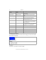
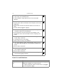
1
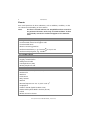
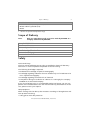
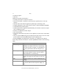
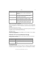
Pump P 2.1S/P 4.1S User Manual V6870 HPLC Note: The contents of this user manual apply for all BlueShadow products. Please submit a request on any article numbers for BlueShadow. Table of Contents 3 Table of Contents Note: For your own safety, read the manual and always observe the warnings and safety information on the device and in the manual! Intended Use . . . . . . . . . . . . . . . . . . . . . . . . . . . . . . . . . . . . . . . . . . . . . . . . . Device Overview . . . . . . . . . . . . . . . . . . . . . . . . . . . . . . . . . . . . . . . . . . . . Features . . . . . . . . . . . . . . . . . . . . . . . . . . . . . . . . . . . . . . . . . . . . . . . . . . Pump Heads . . . . . . . . . . . . . . . . . . . . . . . . . . . . . . . . . . . . . . . . . . . . . . . Eluents . . . . . . . . . . . . . . . . . . . . . . . . . . . . . . . . . . . . . . . . . . . . . . . . . . . 5 5 6 7 8 Scope of Delivery . . . . . . . . . . . . . . . . . . . . . . . . . . . . . . . . . . . . . . . . . . . . . 9 Safety. . . . . . . . . . . . . . . . . . . . . . . . . . . . . . . . . . . . . . . . . . . . . . . . . . . . . . . 9 Definition of Personal and Material Damage . . . . . . . . . . . . . . . . . . . . . . 11 Decontamination . . . . . . . . . . . . . . . . . . . . . . . . . . . . . . . . . . . . . . . . . . 11 Symbols and Signs . . . . . . . . . . . . . . . . . . . . . . . . . . . . . . . . . . . . . . . . . . . 12 Unpacking and Setup . . . . . . . . . . . . . . . . . . . . . . . . . . . . . . . . . . . . . . . . . Contacting the Technical Support . . . . . . . . . . . . . . . . . . . . . . . . . . . . . . Location Requirements . . . . . . . . . . . . . . . . . . . . . . . . . . . . . . . . . . . . . . Requirements . . . . . . . . . . . . . . . . . . . . . . . . . . . . . . . . . . . . . . . . . . . Power supply . . . . . . . . . . . . . . . . . . . . . . . . . . . . . . . . . . . . . . . . . . . Unpacking . . . . . . . . . . . . . . . . . . . . . . . . . . . . . . . . . . . . . . . . . . . . . . . Connecting the Eluent Line to the Pump Head . . . . . . . . . . . . . . . . . . . . Control . . . . . . . . . . . . . . . . . . . . . . . . . . . . . . . . . . . . . . . . . . . . . . . . . . Pin Header for Remote Control . . . . . . . . . . . . . . . . . . . . . . . . . . . . . Controlling with a Computer in a Local Area Network (LAN) . . . . . . . Configuring the LAN Settings . . . . . . . . . . . . . . . . . . . . . . . . . . . . . . Connecting the Cables . . . . . . . . . . . . . . . . . . . . . . . . . . . . . . . . . . . . Configuring the Router . . . . . . . . . . . . . . . . . . . . . . . . . . . . . . . . . . . Integrating the LAN into a Company Network . . . . . . . . . . . . . . . . . . Controlling Several Systems Separately in a LAN . . . . . . . . . . . . . . . . Ground . . . . . . . . . . . . . . . . . . . . . . . . . . . . . . . . . . . . . . . . . . . . . . . . . . 13 13 13 13 14 14 15 16 16 18 18 19 20 20 21 21 Operation . . . . . . . . . . . . . . . . . . . . . . . . . . . . . . . . . . . . . . . . . . . . . . . . . . Switching on the Pump . . . . . . . . . . . . . . . . . . . . . . . . . . . . . . . . . . . . . Selecting the Pump Head . . . . . . . . . . . . . . . . . . . . . . . . . . . . . . . . . . . . Flushing the Pump . . . . . . . . . . . . . . . . . . . . . . . . . . . . . . . . . . . . . . . . . Control . . . . . . . . . . . . . . . . . . . . . . . . . . . . . . . . . . . . . . . . . . . . . . . . . . Keypad . . . . . . . . . . . . . . . . . . . . . . . . . . . . . . . . . . . . . . . . . . . . . . . Software . . . . . . . . . . . . . . . . . . . . . . . . . . . . . . . . . . . . . . . . . . . . . . 22 22 22 22 23 24 27 P 2.1S/P 4.1S User Manual V6870, Version 2.0 4 Table of Contents Switching Off the Pump . . . . . . . . . . . . . . . . . . . . . . . . . . . . . . . . . . . . . 32 Functionality Tests . . . . . . . . . . . . . . . . . . . . . . . . . . . . . . . . . . . . . . . . . . . 32 Troubleshooting . . . . . . . . . . . . . . . . . . . . . . . . . . . . . . . . . . . . . . . . . . . . . 33 LAN . . . . . . . . . . . . . . . . . . . . . . . . . . . . . . . . . . . . . . . . . . . . . . . . . . . . 33 Error List and Solutions . . . . . . . . . . . . . . . . . . . . . . . . . . . . . . . . . . . . . . 34 Maintenance and Care . . . . . . . . . . . . . . . . . . . . . . . . . . . . . . . . . . . . . . . . Contacting the Technical Support . . . . . . . . . . . . . . . . . . . . . . . . . . . . . . Maintenance Contract . . . . . . . . . . . . . . . . . . . . . . . . . . . . . . . . . . . . . . Pump Head . . . . . . . . . . . . . . . . . . . . . . . . . . . . . . . . . . . . . . . . . . . . . . . Removing the Pump Head . . . . . . . . . . . . . . . . . . . . . . . . . . . . . . . . . Installing the Pump Head . . . . . . . . . . . . . . . . . . . . . . . . . . . . . . . . . . Check Valves . . . . . . . . . . . . . . . . . . . . . . . . . . . . . . . . . . . . . . . . . . . . . . Removing the Check Valves . . . . . . . . . . . . . . . . . . . . . . . . . . . . . . . . Cleaning the Check Valves . . . . . . . . . . . . . . . . . . . . . . . . . . . . . . . . . Installing the Check Valves . . . . . . . . . . . . . . . . . . . . . . . . . . . . . . . . . 36 36 37 37 37 38 38 39 39 40 Technical Data. . . . . . . . . . . . . . . . . . . . . . . . . . . . . . . . . . . . . . . . . . . . . . . 41 Accessories and Spare Parts . . . . . . . . . . . . . . . . . . . . . . . . . . . . . . . . . . . . Device and Accessories . . . . . . . . . . . . . . . . . . . . . . . . . . . . . . . . . . . . . . Device Variations . . . . . . . . . . . . . . . . . . . . . . . . . . . . . . . . . . . . . . . . . . Available Pump Heads . . . . . . . . . . . . . . . . . . . . . . . . . . . . . . . . . . . . . . . 42 42 43 43 Disposal . . . . . . . . . . . . . . . . . . . . . . . . . . . . . . . . . . . . . . . . . . . . . . . . . . . . 43 Legal Information . . . . . . . . . . . . . . . . . . . . . . . . . . . . . . . . . . . . . . . . . . . . 44 Warranty Conditions . . . . . . . . . . . . . . . . . . . . . . . . . . . . . . . . . . . . . . . . 44 Transport Damage . . . . . . . . . . . . . . . . . . . . . . . . . . . . . . . . . . . . . . . . . 45 Abbreviations and Terminology . . . . . . . . . . . . . . . . . . . . . . . . . . . . . . . . . 45 Index . . . . . . . . . . . . . . . . . . . . . . . . . . . . . . . . . . . . . . . . . . . . . . . . . . . . . . 46 Declaration of Conformity . . . . . . . . . . . . . . . . . . . . . . . . . . . . . . . . . . . . . 48 P 2.1S/P 4.1S User Manual V6870, Version 2.0 Intended Use 5 Intended Use Note: Only use the device for applications that fall within the range of the intended use. Otherwise, the protective and safety equipment of the device could fail. Device Overview The HPLC pumps P 4.1S/ P 2.1S with pump heads can be used as feed pumps or dosing pumps in analytical or preparative applications. Pumps transport solvents or dissolved samples through the HPLC system. 2 1 3 Fig. 1 P 2.1S with 10 ml pump head Legend 1 Display 4 Fig. 2 P 4.1S with 10 ml pump head 3 Pump head 4 Pressure sensor 2 Keypad 3 2 4 1 5 6 7 8 Fig. 3 Pump, rear view P 2.1S/P 4.1S User Manual V6870, Version 2.0 6 Intended Use Legend 1 2 3 4 Opening of the fan CE mark Serial number 5 6 7 8 LAN port Pin header for remote control Power connection - bushing Hole for the ground connection RS-232 port External devices like computers, fraction collectors, etc. can be connected in 3 different ways: Connected to LAN within a network Connected to RS232, alternately to LAN connection Control with pin header Location In laboratories the device can be used in the following areas: Biochemistry analyses Food analyses Pharmaceutical analyses Environmental analyses Chemical analyses Dosing applications Features Analytical pump head with a flow rate range from 0.001 – 9.999 ml/min and a pressure of up to 400 bar Semi-preparative pump head with a flow rate range from 0.01 – 50 ml/min and a pressure of up to 150 bar Dual-piston technology for constant flow rates Setting a limit for minimum and maximum pressure to protect the columns and to avoid a dry run of the pump (only P 4.1S) Emergency stop, independent from control with chromatography software The pump can be controlled with the keypad in standalone mode or with the chromatography software. The pump heads can be easily removed and replaced via four front-accessible screws by the user. Unlike the pump P 2.1S, pump P 4.1S is equipped with a pressure sensor. Features Liquid transport with stable flow rate and high flow accuracy Long service life P 2.1S/P 4.1S User Manual V6870, Version 2.0 Intended Use 7 Pump heads completely made of stainless steel or with Hastelloy-C or ceramic inlays Piston backflushing High physical and chemical stability Flexible control with LAN connection, RS-232 interface, and analog control signals Control with chromatography software Options A pump in combination with another pump can be used to set up a binary high pressure gradient system. Pump Heads Pump heads for use in analytical applications: Stainless steel with stainless steel inlays for standard applications Stainless steel with ceramics inlays for biocompatibility Stainless steel with Hastelloy-C inlays for aggressive media different pump head sizes: 10 ml or 50 ml The front of the pump head is labeled with the specifications for the maximum pumping capacity (10 ml or 50 ml). Pump heads with inlays carry additional material labels (SST for stainless steel, C for ceramics, HC for Hastelloy-C). 1 2 Fig. 4 Labeling on the pump heads Legend 1 flow rate performance 2 material P 2.1S/P 4.1S User Manual V6870, Version 2.0 8 Intended Use Eluents Even small quantities of other substances, such as additives, modifiers, or salts can influence the durability of the materials. Note: The list of selected solvents was compiled based on research in the pertinent literature and is only a recommendation. If there is any doubt, contact the Technical Support of the manufacturer. Not suitable eluents Halogenated hydrocarbons, e.g. Freon® Concentrated mineral and organic acids Concentrated bases Eluents containing particles Perfluorinated eluents, e. g. Fluorinert® FC-75, FC-40 Perfluorinated polyether, e.g. Fomblin® Less suitable eluents Dimethyl sulfoxide (DMSO) Slightly volatile eluents Methylene chloride Tetrahydrofuran (THF) Dilute phosphoric acid Suitable eluents Acetone at 4°-25° C (39.2°-77.0° F)1 Acetonitrile Benzene Chloroform Ethyl acetate Ethanol Hexane/heptane at 4°-25° C (39.2°-77.0° F)1 Isopropanol Carbon dioxide (liquid 99.999% CO2) MethanolPhosphate buffer solutions (0.5 M) Toluol Dilute ammonia solution P 2.1S/P 4.1S User Manual V6870, Version 2.0 Scope of Delivery 9 Suitable eluents Dilute acetic acid (10-50%), at 25° C/77.0° F Dilute sodium hydroxide (1M) Water 1. valid for the specified temperature range Scope of Delivery Note: Only use original parts and accessories made by KNAUER or a company authorized by KNAUER. Pump P 2.1S/P 4.1S User manual Power adapter 24 V Installation Qualification Document Accessories Kit Pump Accessories Kit AZURA Safety Professional Group The user manual addresses persons who are qualified as chemical laboratory technicians or have completed comparable vocational training. The following knowledge is required: Fundamental knowledge of liquid chromatography Knowledge regarding substances that are suitable only to a limited extent for use in liquid chromatography Knowledge regarding the health risks of chemicals Participation during an installation of a device or a training by the company KNAUER or an authorized company. If you do not belong to this or a comparable professional group, you may not perform the work described in this user manual under any circumstances. In this case, please contact your superior. Safety Equipment When working with the device, take measures according to lab regulations and wear protective clothing: Safety glasses with side protection P 2.1S/P 4.1S User Manual V6870, Version 2.0 10 Safety Protective gloves Lab coat What must be taken into account? All safety instructions in the user manual The environmental, installation, and connection specifications in the user manual National and international regulations pertaining to laboratory work Original spare parts, tools, and solvents made or recommended by KNAUER Good Laboratory Practice (GLP) Accident prevention regulations published by the accident insurance companies for laboratory work Filtration of substances under analysis Use of inline filters Once they have been used, never re-use capillaries in other areas of the HPLC system. Only use a given PEEK fitting for one specific port and never re-use it for other ports. Always install new PEEK fittings on each separate port. Follow KNAUER or manufacturer's instructions on caring for the columns More safety-relevant information is listed in alphabetical order in the following table: Topic Explanations flammability Organic solvents are highly flammable. Since capillaries can detach from their screw fittings and allow solvent to escape, it is prohibited to have any open flames near the analytical system. solvent tray Risk of electrical shock or short circuit if liquids get into the device's interior. For this reason, place all bottles in a solvent tray. solvent lines Install capillaries and tubing in such a way that liquids cannot get into the interior in case of a leak. leaks Regularly check if any system components are leaking. power cable Defective power cables are not to be used to connect the device and the power supply system. P 2.1S/P 4.1S User Manual V6870, Version 2.0 Safety Topic Explanations self-ignition point Only use eluents that have a self-ignition point higher than 150 °C under normal ambient conditions. power strip If several devices are connected to one power strip, always consider the maximum power consumption of each device. power supply Only connect devices to voltage sources, whose voltage equals the device's voltage. toxicity Organic eluents are toxic above a certain concentration. Ensure that work areas are always well-ventilated! Wear protective gloves and safety glasses when working on the device! 11 Where is use of the device prohibited? Never use the system in potentially explosive atmospheres without appropriate protective equipment. For further information, contact the Technical Support of KNAUER. Decommissioning the Device Securely At any time, take the device completely out of operation by either switching off the power switch or by pulling the power plug. Opening the Device The device may be opened by the KNAUER Technical Support or any company authorized by KNAUER only. Definition of Personal and Material Damage Possible dangers related to the device are divided into personal and material damage in this user manual. Category Explanations DANGER! Lethal or very serious injuries can occur. WARNING! Serious or moderate injuries can occur. CAUTION! Moderate injuries can occur. Device defects can occur. Decontamination Contamination of devices with toxic, infectious or radioactive substances poses a hazard for all persons during operation, repair, sale, and disposal of a device. P 2.1S/P 4.1S User Manual V6870, Version 2.0 12 Symbols and Signs DANGER! Health danger if getting in contact with toxic, infectious or radio-active substances. Before disposing of the device or sending it away for repair, you are required to decontaminate the device adequately. All contaminated devices must be properly decontaminated by a specialist company or the operating company before they can be recommissioned, repaired, sold, or disposed of. All materials or fluids used for decontamination must be collected separately and disposed of properly. Symbols and Signs The following symbols and signs can be found on the device, in the chromatography software or in the user manual: Symbol Meaning High-voltage hazard Electric shock hazard Electrostatic discharge hazard, damages to system, device, or components can occur. General warning sign, moderate injuries can occur and also damages to system, device, or components. UV-light hazard, eye injuries can occur. Leak hazard, damages to device can occur. P 2.1S/P 4.1S User Manual V6870, Version 2.0 Unpacking and Setup Symbol 13 Meaning Hazardous substances. A device or system marked with CE fulfills the product specific requirements of European directives. This is confirmed in a Declaration of Conformity. Testing seals in Canada and the USA at nationally recognized testing centers (NRTL). The certified device or system has successfully passed the quality and security tests. Unpacking and Setup Contacting the Technical Support You have various options to contact the technical support: Phone: +49 30 809727-111 Fax: +49 30 8015010 E-mail: [email protected] Location Requirements Requirements The location for the device must meet the following requirements: CAUTION Defect of the device due to overheating possible. - Set up the device in such a way that it is protected against exposure to direct sunlight. - Keep at least 15 cm clear at the rear and 5–10 cm at each side for air circulation. Weight 1.5 kg Dimensions 105 × 100 × 185 mm (Width × Height × Depth) Power supply 24 V DC P 2.1S/P 4.1S User Manual V6870, Version 2.0 14 Unpacking and Setup Air humidity < 90 % Temperature 4 – 40 °C (39.2 – 104 °F) Space requirements Side clearance to other devices: If there is a device on one side, minimum clearance of 5 cm. If there are devices on both sides, minimum clearance of 10 cm At least 30 cm gap to the fan on the rear of the device. Power supply The device is intended for use with AC power networks of 100 – 240 V. Power cable Only the supplied power cable is to be used to connect the device to the mains supply. Replace defective power cables only with accessories from KANUER. Only use power cables with a permission for use from your country. Power plug Make sure that the power plug on rear of the device is always accessible, so that the device can be disconnected from the power supply. Unpacking Store all packing material. Retain included packing list carefully for repeat orders. CAUTION Damage to the device by carrying or lifting it on protruding housing parts. Lift the device on the side of the housing only. 1. Setup the delivery so you are able to read the label. Using the utility knife, cut the adhesive tape. Open the delivery. 2. Remove the foam insert. Take out the accessories kit and the manual. 3. Open the accessories kit and take out all accessories. In case any parts are missing, contact the technical support. Grip the device at its side panels and lift it out of the packaging. 4. Remove the foam inserts from the device. Pull off the antistatic bag, if necessary. 5. Check for damages caused during transportation. In case you notice any damage, contact the technical support. P 2.1S/P 4.1S User Manual V6870, Version 2.0 Unpacking and Setup 15 6. Set-up the device in its location. 7. Check the scope of delivery 8. Remove the protective foil. Result The device is complete and ready for use. Next steps Connect the device to power supply to prepare the initial startup. Connecting the Eluent Line to the Pump Head Prerequisites The device has been switched off. The power plug has been pulled. Material Flangeless fitting CAUTION Damage to the pump head possible! Remove the cap fittings from the inlet and outlet of the pump head prior to use! Process Figure 1. Slide the flangeless fitting onto the tubing. 2. Insert the tubing into the free inlet 1 on the bottom of the pump head. 3. Tighten the fitting by hand. 1 Fig. 5 Solvent line on the pump head Next steps Integrate the pump into the HPLC flow system. P 2.1S/P 4.1S User Manual V6870, Version 2.0 16 Unpacking and Setup Control 2 1 3 4 5 6 7 9 8 Fig. 6 Pump, rear view Legend 1 2 3 4 CE mark Opening of the fan Serial number RS-232 port 5 6 7 8 9 LAN port Pin header for remote control Power connection - bushing Warning 1 Hole for the ground connection Pin Header for Remote Control Contact data Explanation GROUND Reference point of the voltage at the signal inputs. START IN TTL-compatible input min. 10 mA Low active After receiving a signal from an external device, the device starts. If controlled with software, an electronic trigger is send through the LAN. P 2.1S/P 4.1S User Manual V6870, Version 2.0 Unpacking and Setup Contact data Explanation ERROR IN/OUT TTL-compatible input min. 10 mA Low active 17 After receiving a signal (e. g. short-circuit to ground) from an external device, an error message appears and the device stops. ANALOG IN Flow rate is controlled through external control voltage (0 – 10 V). ANALOG OUT Analog output signal for reproducing the measured system pressure. Connecting the Pin Header To control one device through another, you use the multi-pin connector. To use remote control, you have to connect cables to the terminal strip (everything comes included with delivery). The single ports are used to exchange control signals. Prerequisites The device has been turned off. The power plug has been pulled. Tools Depressor tool CAUTION Short-circuit hazard. - Turn off the device before connecting it to the multi-pin connector. - Pull the power plug. CAUTION Electrostatic discharge can destroy the electronics. Wear a protective bracelet against electrostatic discharge and ground. P 2.1S/P 4.1S User Manual V6870, Version 2.0 18 Unpacking and Setup Process Figure 1. Place the terminal strip 3 on a suitable surface. 2. Push the depressor tool 1 into the opening on the upper side. 3. Continue pushing the depressor tool down and lead the cable 2 into the front end of the terminal strip. 1 2 4. Remove the depressor tool. 5. Check whether the cables are tightly attached. 6. Plug the terminal strip onto the Fig. 7 multi-pin connector. 3 terminal strip Next steps Finish the installation and perform the initial startup. Controlling with a Computer in a Local Area Network (LAN) This section describes how to set up an HPLC system in a local area network (LAN) and how a network administrator can integrate this LAN into your company network. The description applies to the operating system Windows® and all conventional routers. Note: To set up a LAN, we recommend to use a router. That means the following steps are required: Process 1. On the computer, go to the control panel and check the LAN properties. 2. Hook up the router to the devices and the computer. 3. On the computer, configure the router to set up the network. 4. Install the chromatography software from the data storage device. 5. Switch on the device and run the chromatography software. Configuring the LAN Settings The LAN uses only one server (which is normally the router) from that the devices automatically receive their IP address. P 2.1S/P 4.1S User Manual V6870, Version 2.0 Unpacking and Setup 19 Prerequisite In Windows®, power saving, hibernation, standby, and screen saver must be deactived. In case you use an USB-to-COM box, the option "Allow the computer to turn off ths device to save power" in the devicemanager must be deactivated for all USB hosts. Only for Windows 7: For the network adapter, the option "Allow the computer to turn off this device to save power" in the Device Manager must be deactivated. Procedure 1. In Windows 7 choose Start Control Panel Network and Sharing Center. 2. Double-click on LAN Connection. 3. Click on the button Properties. 4. Select Internet Protocol version 4 (TCP/IPv4). 5. Click on the button Properties. 6. Check the settings in the tab General. The correct settings for the DHCP client are: a) Obtain IP address automatically b) Obtain DNS server address automatically 7. Click on the button OK. Connecting the Cables A router has several LAN ports and one WAN port that can be used to integrate the LAN into a wide area network (WAN), e.g. a company network or the Internet. In contrast, the LAN ports serve to set up a network from devices and a computer. To avoid interference, we recommend operating the HPLC system separately from the company network. You will find patch cables for each device and the router in the accessories kit. To connect the router to a WAN, an additional patch cable is required, which is not supplied within the scope of delivery. 1 Modules 2 Router 3 LAN ports 4 WAN port 5 Workstation P 2.1S/P 4.1S User Manual V6870, Version 2.0 20 Unpacking and Setup 1 Fig. 8 2 3 4 5 Cabling system LAN Prerequisite The computer has been switched off. There is a patch cable for each device and the computer. Procedure 1. Use the patch cable to connect the router and the computer. Repeat this step to connect all devices. 2. Use the power supply to connect the router to the mains power system. Configuring the Router The router is preset at the factory. You will find a label at the bottom side of the router, on which IP address, user name, and password are printed. These information help to open the router configuration. Procedure 1. To open the router configuration, start your Internet browser and enter the IP address (not for all routers). 2. Enter user name and password. 3. Configure the router as DHCP server. 4. In the router configuration, check the IP address range and make changes if necessary. Result Once the router has assigned IP addresses to all devices, the chromatography software can be used to remotely control the system. Integrating the LAN into a Company Network A network administrator can integrate the LAN into your company network. In this case you use the WAN port of the router. P 2.1S/P 4.1S User Manual V6870, Version 2.0 Unpacking and Setup 21 Prerequisite There is a patch cable for the connection. Procedure 1. Check that the IP address range of the router and of the company network do not overlap. 2. In case of an overlap, change the IP address range of the router. 3. Use the patch cable to connect the router WAN port to the company network. 4. Restart all devices, including the computer. Controlling Several Systems Separately in a LAN Devices connected to a LAN communicate through ports, which are part of the IP address. If more than one HPLC system is connected to the same LAN and you plan on controlling them separately, you can use different ports to avoid interference. Therefore, the port number for each device must be changed and this same number must be entered into the device configuration of the chromatography software. We recommend to use the same port number for all devices in the same system. Note: The port is set to 10001 at the factory. You must use the same numbers in the device configuration of the chromatography software as in the device, otherwise the connection fails. Procedure 1. Find out port number and change it on the device. 2. Enter the port number in the chromatography software. Result The connection is established. Ground CAUTION! Electronic hazard when using an identically constructed power adapter from another manufacturer. Before establishing a power connection, call the Technical Support. The ground connection for the pump has a designated hole with a thread M3 on the back of the device. If the supplied power adapter is used, then the ground connection remains unused. P 2.1S/P 4.1S User Manual V6870, Version 2.0 22 Operation Please contact the technical support of KNAUER, if the pump along with other devices should be connected to the power supply with a 6-prong power adapter; a pump needs to be grounded exclusively. Operation Switching on the Pump CAUTION! Damage to the pump head in case it runs dry. Ensure that liquids runs through pump head and piston backflushing. Procedure 1. Connect the power adapter to the power supply. 2. Connect the pump with plug from the external power adapter. 3. Switch on the power adapter. 4. Wait until the pump has completed the self-test. Result After the device is switched on, the display shows Pump and the Firmware version. The device performs a self-test. After all tests have been successfully completed, the status of the pump with its current flow rate is displayed. The pump is ready for operation. Selecting the Pump Head Procedure Figure 1. Press both arrow keys simultaneously until the correct display appears. 2. Let go of the arrow keys. 3. Using the arrow keys, scroll until 10 ml/50 ml. HEAD: HEAD: 50ml 10ml Fig. 9 Pump head selection Result When setting is finished, the status display appears. Flushing the Pump The display shows vertical arrows while the pump is flushing. P 2.1S/P 4.1S User Manual V6870, Version 2.0 Operation 123 9.876 1 23 2 3 Legend 1 Flushing symbol 2 Pressure 3 Flow rate Prerequisites Pump with pressure sensor: Venting screw of the pressure sensor is open. Syringe is connected to venting capillary. Pump without pressure sensor: Blind fitting in the outlet to the pressure sensor is removed. Syringe is connected to the capillary on the pump-head outlet. Note: The flow rate can be changed while being purged. The change takes effect immediately. Process Figure 1. Prime liquid with the syringe. 2. Hold down start/stop key until flushing starts. Control The pump can be operated in two ways: Using the buttons at the device Using the software ClarityChrom® or ChromGate® Note: Operator errors and clogged capillaries can cause high pressure spikes. The status display shows the flow rate and also the pressure for pumps with pressure sensor. P 2.1S/P 4.1S User Manual V6870, Version 2.0 24 Operation 1 2 Fig. 10 Status display Legend 1 Pressure in 0,1 MPa 2 Flow rate in ml/min Keypad The keypad consists of 3 keys, which allow monitoring the device or changing the settings. Figure Function Press both keys simultaneously to scroll. Press any of the arrow keys to set values and to change settings. Fig. 11 Arrow keys Starting and stopping the pump. Flushing the pump. Fig. 12 Start/stop key Setting the Flow Rate In case of the pump without pressure sensor the actual required flow rate is dependent on the resulting counter pressure. The absolute deviation is dependent on the compressibility and the viscosity of the used solvent and on the pump. Therefore, it must be determined individually for each pump. The flow rate can be altered while the pump is in operation. Practical Tip! Process Hold down both arrow keys to expedite changing the values. Figure 1. Use the arrow keys to set a value for the flow rate. 2. Check if the right value appears on the display. Fig. 13 Display control Result The setting is completed and the pump runs at the set flow rate. P 2.1S/P 4.1S User Manual V6870, Version 2.0 Operation 25 Setting the Pressure Switch Off • Set maximum pressure to avoid damaging the pump or pump head. • Set minimum pressure to avoid running the pump dry. P P 123 9 1 2 Legend 1 Maximum value 2 Minimum value Note: If the minimum is set to 0, the minimum pump pressure is not monitored. Process Figure 1. Press both arrow keys simultaneously until the correct display appears. 2. Let go of the arrow keys. 3. When the cursor flashes, use the arrow keys again to set the value for the maximum pressure. 4. Hold down left arrow key. Press right arrow key once. 5. When the cursor flashes, use the arrow keys again to set the value for the minimum pressure. 6. Hold down left arrow key. Press right arrow key once to return to the start display. P 123 Fig. 14 Maximum pressure P 9 Fig. 15 Minimum pressure Result The setting is completed. If the maximum pressure is exceeded, the pump switches off. If the minimum pressure is undercut, the pump switches off after 30 s. The display shows an error message in both cases. Setting the Power Consumption The power consumption is dependent on the flow rate and the counter pressure. It increases with higher flow rates and stronger counter pressure. P 2.1S/P 4.1S User Manual V6870, Version 2.0 26 Operation • Exceeding or undercutting the values for the maximum or minimum power consumption leads to the pump being automatically shutdown. • Set the maximum power consumption for the pump without pressure sensor to limit the pump pressure. • Set the minimum power consumption so as to avoid a dry run of the pump at highly reduced maximum power consumption (e. g. if leaking). The pump is preset to a standard value for the maximum power consumption. KNAUER recommends that with smaller flow rates the standard value for the maximum power consumption should be insignificantly decreased. I I 050 000 1 2 Legend 1 Maximum value 2 Minimum value Note: If the minimum is set to 0, the minimum power consumption is not monitored. Process Figure 1. Press both arrow keys simultaneously until the correct display appears. 2. Let go of the arrow keys. 3. When the cursor flashes, use the arrow keys again to set the value for the maximum power consumpFig. 16 Minimum power consumption tion. 4. Hold down left arrow key. Press right arrow key once. I 050 I 000 5. When the cursor flashes, use the arrow keys again to set the value for the minimum power consumpFig. 17 Maximum power consumption tion. 6. Press start/stop key once to return to the start display. P 2.1S/P 4.1S User Manual V6870, Version 2.0 Operation 27 Result The setting is completed. If the value for maximum power consumption is exceeded, the pump switches off. Flushing the Pistons When you flush the pistons regularly, the service life of the seals and pistons increases. While flushing, contaminants are washed from the rear piston area. The following solvents are recommended for flushing the columns: Water Mixture of 80 % water and 20 % ethanol Isopropanol Process Figure 1. Connect the outlet to the waste 2 1 container with a hose 1. 2. Connect the inlet to the syringe with a hose 2. 3. Fill up flushing solution with the syringe through the pump head until there are no more air bubbles running through the waste bottle. Fig. 18 Flushing rear piston area 4. Afterwards, remove the hoses and connect inlet and outlet with a hose. Software To be able to control the pump using chromatography software, the computer must be connected to the device either with a RS232 cable or a LAN cable. Via Local Area Network (LAN) A device connected to a LAN is recognized by the software and automatically receives an IP address because it is set to Dynamic Host Configuration Protocol (DHCP) at the factory. Prerequisite Device has been connected to LAN. Status display is active. P 2.1S/P 4.1S User Manual V6870, Version 2.0 28 Operation Process Figure 1. Press both arrow keys simultaneously until the correct display appears. 2. Let go of the arrow keys. 3. Using the arrow keys, scroll until LAN. Fig. 19 Display control Results When setting is finished, the status display appears. Via RS-232 Port Prerequisite Interface RS-232 is connected. Status display is active. Process Figure 1. Press both arrow keys simultaneously until the correct display appears. 2. Let go of the arrow keys. 3. Using the arrow keys, scroll until RS-232 is displayed. Fig. 20 Display control Results When setting is finished, the status display appears. Changing to Analog Control Prerequisite Interfaces ANALOG IN and ANALOG OUT on the pin header are connected. Status display is active. Process Figure 1. Press both arrow keys simultaneously until the correct display appears. 2. Let go of the arrow keys. 3. Using the arrow keys, scroll until ANALOG is displayed. PC: ANALOG Fig. 21 Display control P 2.1S/P 4.1S User Manual V6870, Version 2.0 Operation 29 Results When setting is finished, the status display appears. Control commands The control commands listed below are considered for the communication with RS-232 and LAN. When entering a parameter, you must place a colon or space between command and parameter value, e. g. PMIN10:100. Consider the following specifications for data transfer with RS-232 interface: 9600 baud 8 bit 1 stop-bit no parity check Control command Range and specification Description ADJ10(?) RD/WR 100 – 2000 Adjust parameter for 10 ml pump head ADJ50(?) RD/WR 100 – 2000 Adjust parameter for 50 ml pump head CORR10(?) RD/WR 0 – 300 Correction parameter for 10 ml pump head CORR50(?) RD/WR 0 – 300 Correction parameter for 50 ml pump head FLOW(?) RD/WR 0 – 50000 Writing/reading the flow in μl/min PRESSURE? RD 0 – 400 Pressure readout in 0.1 MPa PMIN10(?) RD/WR 1 – 400 Minimum pressure for 10 ml pump head (in 0.1 MPa) PMIN50(?) RD/WR 150 Minimum pressure for 50 ml pump head (in 0.1 MPa) PMAX10(?) RD/WR 0 – 400 Maximum pressure for 10 ml pump head (in 0.1 MPa) PMAX50(?) RD/WR 0 – 150 Maximum pressure for 50 ml pump head (in 0.1 MPa) IMIN10(?) RD/WR 0 – 100 Minimum motor current for 10 ml pump head IMIN50(?) RD/WR 0 – 100 Minimum motor current for 50 ml pump head IMAX10(?) RD/WR 0 – 100 Maximum motor current for 10 ml pump head P 2.1S/P 4.1S User Manual V6870, Version 2.0 30 Operation Control command Range and specification Description IMAX50(?) RD/WR 0 – 100 Maximum motor current for 50 ml pump head HEADTYPE(?) RD/WR 10, 50 Writing/reading the pump-head type STARTLEVEL(?) RD/WR 0,1 Sets logical level of the START-IN input to start the flow delivery ERRIO(?) RD/WR 0,1 Writing/reading the ERROR input/ output, OUT (0) or IN (1) STARTMODE(?) RD/WR 0,1 0 = Pump pauses after switch on 1 = Pump starts with last used flow rate at switch on EXTCONTR WR 0,1 0 = Prevents external flow control 1 = Allows flow control through analog input (1 V = 1(5) ml/min) EXTFLOW? RD IMOTOR? RD 0 – 100 Motor current in relative units LOCAL WR Put the instrument in local mode REMOTE WR Put the instrument in remote mode ERRORS? RD Returns 5 last saved errors ON WR Start flow OFF WR Stop flow Controlling the Flow Rate To control the flow rate by an external control voltage, you need to select ANALOG control in the menu. 1 2 Fig. 22 Status display Legend 1 Pressure in 0,1 MPa 2 Flow rate in ml/min Prerequisite The pump is connected to the power supply. P 2.1S/P 4.1S User Manual V6870, Version 2.0 Operation 31 Procedure 1. Apply control voltage. 2. Press the Start/Stop button, so as to start the pump. The star symbol on the display of the pump indicates that the pump is working with an externally controlled flow rate. 3. To stop the pump, press the start/stop key again. Starting with a Short-Circut Connection for the short circuit (or TTL-low) for interrupting and continuing the operation of the pump. The operation of the pump is dependent on the STARTLEVEL setting: STARTLEVEL 1 (standard setting RS-232, LAN): The pump does not operate during the time of short-circuit. STARTLEVEL 0 (standard setting Analog): The pump operates during the time of short-circuit. 1 2 Fig. 23 Status display Legend 1 Pressure in 0,1 MPa 2 Flow rate in ml/min Enter STARTLEVEL:1 in the terminal program, to stop the pump during short-circuit. Prerequisite The pump is connected to the power supply. Note: During the interruption, the horizontal arrow remains in the display, because the pump is still in operation status. Procedure 1. Connect the pump to a suitable terminal program. 2. Connect the pump using a LAN or RS-232. 3. Enter STARTLEVEL:1. Starting Directly after Connecting to Power Supply By default the pump is stopped and started using the start/stop button. The STARTMODE setting allows you to start the device right after connecting it to power supply. P 2.1S/P 4.1S User Manual V6870, Version 2.0 32 Functionality Tests STARTMODE 0 (default setting RS-232, LAN): The pump does not start operating right after being connected to power supply. STARTMODE 1 (default setting Analog): The pump starts operating right after being connected to power supply. Enter in the terminal program using RS-232 STARTMODE:1, so that the pump is in operation directly after being connected to the power supply. Prerequisite The pump is connected to the power supply. Procedure 1. Connect the pump to a suitable terminal program. 2. Connect the pump using a LAN or RS-232. 3. Enter STARTMODE:1. Switching Off the Pump If you want to switch off the pump for a longer term, flush the pump head with isopropanol. Functionality Tests Installation Qualification (IQ) The customer may request the Installation Qualification, which is free of charge. In case of a request, the Technical Support of KNAUER or from a provider authorized by KNAUER performs this functionality test during the installation. The Installation Qualification is a standardized document that comes as part of the delivery and includes the following: confirmation of flawless condition at delivery check if the delivery is complete certification on the functionality of the device Operation Qualification (OQ) The Operation Qualification includes an extensive functionality test and must be purchased from the manufacturer. Contact the KNAUER Sales Department to request an offer. The Operation Qualification is a standardized KNAUER document and includes the following: definition of customer requirements and acceptance terms documentation on device specifications device functionality check at installation site P 2.1S/P 4.1S User Manual V6870, Version 2.0 Troubleshooting 33 Test Intervals To make sure that the device operates within the specified range, you should test the device using the Operation Qualification at following intervals: Average Useful Life OQ Test 1 to 5 days/week: Every 6 months More than 5 days/week or 24 hours/day: Every 3 months Operation with buffer solutions or other salt solutions: Every 3 months Execution The test can be carried out either by the Technical Support of KNAUER or from a provider authorized by KNAUER. Troubleshooting First measures for troubleshooting: Check all screw fittings Check whether air has gotten into the supply lines Check device for leaks Further measures: Check errors against error list Contact the technical support of KNAUER LAN Go through the following steps, in case no connection between the computer and the devices can be established. Check after each step if the problem is solved. If the problem cannot be located, call the Technical Support. 1. Check the status of the LAN connection in the Windows task bar: Connected Connection not established If no connection was established, test the following: Is the router switched on? Is the patch cable connected correctly to the router and the computer? P 2.1S/P 4.1S User Manual V6870, Version 2.0 34 Troubleshooting 2. Check the router settings: Is the router set to DCHP server? Is the IP address range sufficient for all the connected devices? 3. Check all connections: Are the patch cable connected to the LAN ports and not the WAN port? Are all cable connections between devices and router correct? Are the cables plugged in tightly? 4. If the router is integrated into a company network, pull out the patch cable from the WAN port. Can the devices communicate with the computer, even though the router is disconnected from the company network? 5. In case you own a Control Unit, check the settings in the menu Setup > Network. Is LAN-DHCP set for controlling? Did the device receive an IP address? 6. Turn off all devices, router, and computer. Firstly, turn on the router and secondly turn on the devices and the computer. Has this been successful? 7. Replace the patch cable to the device with that no connection could be established. Has this been successful? 8. Make sure that the IP port of the device matches the port in the chromatography software. Error List and Solutions Problem Solution Pump will not turn on Power cable needs to be connected to power supply and power adapter has to be turned on. • Inspect the power cable to ensure that it is plugged into the power supply. P 2.1S/P 4.1S User Manual V6870, Version 2.0 Troubleshooting Problem Solution When purging, the pump switches off The venting screw on the pressure sensor must be turned up. 35 • Check if the venting screw on the pressure sensor is turned open. Pump does not transport solvent Check the following options: • Purge the pump head so as to remove the air bubbles • Inspect the eluent inlet and filter of the HPLC column and change when blocked. • Replacing the pump head • Clean the check valves • Exchange the check valves • If the pump head seals are defective, solvent enters the piston backflushing; inform the technical support of KNAUER. Pressure or flow rate Check the following options: fluctuations • Purge the pump head so as to remove the air bubbles • Always tighten the inlet screw and outlet screw on the pump head with a torque wrench and 7.5 Nm. Clean the check valves • Exchange the check valves Pump head leaks Check the following options: • Inspect the inlet and outlet screw fittings of the pump head • Replacing the pump head • If the pump head seals are defective, solvent enters the piston backflushing; inform the technical support of KNAUER. P 2.1S/P 4.1S User Manual V6870, Version 2.0 36 Maintenance and Care Problem Solution Flow rate is not cor- Check the following options: rect • Inspect the inlet and outlet screw fittings of the pump head • Clean the check valves • Exchange the check valves • Replacing the pump head • Pump without pressure sensor: Pay attention to the influence of the pressure on the flow rate (will not be compensated). • Inform the Technical Support of KNAUER. Pump will not turn on Power cable needs to be connected to power supply and power adapter has to be turned on. • Inspect the power cable to ensure that it is plugged into the power supply. Maintenance and Care Proper maintenance of your HPLC device will ensure successful analyses and reproducible results. CAUTION! Intruding liquids can cause damage to the device. - Place solvent bottles next to the device or in a solvent tray. - Moisten the cleaning cloth only slightly. All smooth surfaces of the device can be cleaned with a mild, commercially available cleaning solution, or with isopropanol. Users may perform the following maintenance tasks themselves: Replacing the pump head Exchanging the check valves Contacting the Technical Support If you have any technical questions regarding the hardware or software of the manufacturer, please use one of the contact options below: European Technical Support Hotline: Languages: German and English Available by telephone: 8 am to 5 pm (CET) P 2.1S/P 4.1S User Manual V6870, Version 2.0 Maintenance and Care 37 Phone: +49 30 809727 111 Fax: +49 30 8015010 E-mail: [email protected] (manufacturer) Proper maintenance of your HPLC device will ensure successful analyses and reproducible results. Maintenance Contract The following maintenance work on the device may only be performed by KNAUER or a company authorized by KNAUER and is covered by a separate maintenance contract: • Opening the device or removing housing parts. Pump Head Removing the Pump Head Requirements The pump head has been flushed with suitable solvent. WARNING! Aggressive or toxic solvent residue can irritate the skin! Wear protective gloves. Flush the pump head before exchanging it. CAUTION! Piston rods can break. Before disassembling the pump head, remove the two piston rods and deposit in the correct orientation. When assembling the pump head, the piston rods must be inserted on the same side they have been removed from. P 2.1S/P 4.1S User Manual V6870, Version 2.0 38 Maintenance and Care Process Figure 1. Unscrew inlet fitting 2 and outlet fitting 1. 1 2. Unscrew the inlet fitting 5 to the eluent. 2 3. Unscrew the outlet fitting 4 to the pressure sensor. 4. Alternately unscrew the 4 fastening screws 3. 5. Hold the pump head and consecutively pull out all fastening screws. 3 4 5 Installing the Pump Head CAUTION! Damage to the pump head caused by overtightened capillary fittings! Note the torque of the fittings: - 5 Nm for stainless-steel fittings - 0.5 Nm for PEEK fittings Process Figure 1. Insert the fastening screws 3 and tighten alternately. 1 2. Tighten the outlet fitting 4 to the pressure sensor. 2 3. Tigthen the inlet fitting 5 to the eluent. 3 4. Tighten the inlet fitting 2 and the outlet fitting 1 of the piston. 4 5 Check Valves Dirty check valves do not open and close properly. They cause pressure fluctuations and irregular flow. Note: Insert the valves in the direction of flow! P 2.1S/P 4.1S User Manual V6870, Version 2.0 Maintenance and Care 39 Fig. 24 Check valve Removing the Check Valves The pump head is equipped with two check valves. Prerequisite The pump head has been purged. The capillary and tubing have been removed. The pump head has been removed. Tools Open-end wrench, size 13 Process Figure 1. Unscrew and remove the capillary connector 1. 1 2. Loosen the outlet fitting 2 with the open-end wrench. 3. Remove the first check valve. 2 4. Loosen the inlet fitting 3 with the open-end wrench. 5. Remove the second check valve. 3 Fig. 25 Check valve in pump head Next steps Clean the check valves. Cleaning the Check Valves 1. Fill a beaker with solvent. P 2.1S/P 4.1S User Manual V6870, Version 2.0 40 Maintenance and Care 2. Place the valve in the beaker. 3. Put the beaker in an ultrasonic bath for at least 10 minutes. Installing the Check Valves Insert the check valves in the direction of the flow. The notch of the check valve points downward. Insert the NP check valves in the direction of the flow. The arrow on the NP check valve points upward. Prerequisite The check valves have dried. CAUTION Damage to components caused by overtightened fittings! Note the torque of the fittings: - For stainless-steel fittings: 5 Nm - For PEEK fittings: maximum 1 Nm or finger-tight and an additional quarter of a turn with appropriate pliers. Process Figure 1. Insert the check valves 1 in such a way that the notch of the check valve 2 points downward. 1 2. Screw in inlet and outlet fittings and tighten them with a torque wrench and the respective torque. 2 Fig. 26 Check valve Next steps Re-install the pump head. P 2.1S/P 4.1S User Manual V6870, Version 2.0 Technical Data 41 Technical Data Solvent delivery Pump type Dual-piston pump with main and auxiliary piston Flow rate range 10 ml pump head: 0.001 - 10 ml/min 50 ml pump head: 0.01 - 50 ml/min Maximum pressure 10 ml pump head: 40 MPa to 10 ml/min Imax = 70 50 ml pump head: 15 MPa to 50 ml/min Imax = 80 Flow rate accuracy ± 1%, measured at 5 - 50% of flow range using ethanol/water 10:90 For pumps without a pressure sensor dependent on pressure Flow rate precision Relative standard deviation RSD: < 0.5 % (1 ml/min) Gradients Isocratic HPLC pump Expandable to a binary high pressure gradient system (controlled by software) System protection Pump with pressure sensor: Pmin and Pmax adjustable Imin and Imax adjustable Pump with pressure sensor: Imin and Imax adjustable P 2.1S/P 4.1S User Manual V6870, Version 2.0 42 Communication Accessories and Spare Parts Operation Analog inputs 0 – 10 V Supply frequency 50-60 Hz Active power consumption maximum 40 W Protection IP-20 Technical parame- Temperature range ters Humidity General LAN RS-232 Analog Buttons on the device 4 – 40 °C; 39.2 – 104 °F below 90 % non-condensing Power supply 100 – 240 V; 50 – 60 Hz Dimensions Pump without pressure sensor: 220 × 121 × 138.1 mm Pump with pressure sensor: 121 × 138.1 × 227.8 mm (width x height × depth) Weight Pump without pressure sensor: 2.3 kg Pump with pressure sensor: 2.4 kg Height above sea level maximum 2000 m Accessories and Spare Parts For repeat orders of spare parts use the enclosed packing list. Contact the Technical Support in case there are any questions on spare parts or accessories. Device and Accessories Name Order number Pump APG20 Accessories kit AZURA FZA01 Accessories kit P 2.1S/P 4.1S FPGA User manual V6870 P 2.1S/P 4.1S User Manual V6870, Version 2.0 Disposal 43 Device Variations Bezeichnung Bestellnummer Pump P 4.1S with 10 ml pump head (stainless steel) APG20EA Pump P 4.1S with 10 ml pump head (ceramic) APG20EB Pump P 4.1S with 50 ml pump head (stainless steel) APG20FA Pump P 4.1S with 50 ml pump head (ceramic) APG20FB Pump P 2.1S with 10 ml pump head (stainless steel) APG90EA Pump P 2.1S with 10 ml pump head (ceramic) APG90EB Pump P 2.1S with 10 ml pump head (Hastelloy-C) APG90EC Pump P 2.1S with 50 ml pump head (stainless steel) APG90FA Pump P 2.1S with 50 ml pump head (ceramic) APG90FB Available Pump Heads Name Order number 10 ml pump head with stainless-steel inlay AHB40 10 ml pump head with ceramic inlay AHB32 10 ml pump head with Hastelloy-C inlay AHB43 50 ml pump head with ceramic inlay AHC22 50 ml pump head with stainless-steel inlay AHC20 Disposal Hand in old devices or disassembled old components at a certified waste facility, where they will be disposed of properly. AVV Marking in Germany According to the German "Abfallverzeichnisverordnung" (AVV) (January, 2001), old devices manufactured by KNAUER are marked as waste electrical and electronic equipment: 160214. WEEE Registration KNAUER as a company is registered by the WEEE number DE 34642789 in the German "Elektroaltgeräteregister" (EAR). The number belongs to category 8 and 9, which, among others, comprise laboratory equipment. All distributors and importers are responsible for the disposal of old devices, as defined by the WEEE directive. End-users can send their old devices manufac- P 2.1S/P 4.1S User Manual V6870, Version 2.0 44 Legal Information tured by KNAUER back to the distributor, the importer, or the company free of charge, but would be charged for the disposal. Solvents and Other Operating Materials All solvents and other operating materials must be collected separately and disposed of properly. All wetted components of a device, e. g. flow cells of detectors or pump heads and pressure sensors for pumps, have to be flushed first with isopropanol and then with water before being maintained, disassembled or disposed. Legal Information Warranty Conditions The factory warranty for the device is valid for 12 months after the date of dispatch. All warranty claims shall expire in the event that any unauthorized changes are made to the device. During the warranty period, any components with material or design-related defects will be replaced or repaired by the manufacturer free of charge. This warranty excludes the following: accidental or willful damage damage or errors caused by third parties that are not contractually related to the manufacturer at the time the damage occurs wear parts, fuses, glass parts, columns, light sources, cuvettes and other optical components damage caused by negligence or improper operation of the device and damage caused by clogged capillary packaging and transport damage In the event of device malfunctions, directly contact the manufacturer. KNAUER Wissenschaftliche Geräte GmbH Hegauer Weg 38 14163 Berlin, Germany Phone: +49 30 809727-111 Telefax: +49 30 8015010 e-mail: [email protected] Internet: www.knauer.net P 2.1S/P 4.1S User Manual V6870, Version 2.0 Abbreviations and Terminology 45 Transport Damage The packaging of our devices provides the best possible protection against transport damage. Check the devices for signs of transport damage. In case you notice any damage, contact the Technical Support and the forwarder company within three workdays. Abbreviations and Terminology Here you can find information on the abbreviations and terminology used in this manual. Term Explanations GLP Good Laboratory Practice - quality assurance for laboratories HPG High Pressure Gradient. Operating mode of an HPLC system. The solvent is mixed on the high pressure side of the pump. HPLC High Performance Liquid Chromatography. Solvent Mobile phase (eluent) or carrier for liquid chromatography Remote External control with chromatography software or analog control signals P 2.1S/P 4.1S User Manual V6870, Version 2.0 46 Index Index leak 10 Line voltage 14 Location 13 A Accessories 9 Additives 8 AVV marking 43 M C Maintenance 36 Cap fitting 15 Care 36 Check valves Modifiers 8 maintenance contract 37 O Cleaning 39 Exchanging 38 Removing 39 Operation Arrow keys 24 Cleaning 36 Connectors on the Rear Side 16 Contact 36 Controlling the pump 22 D declaration of conformity 48 decontamination 11 Device safety 9 E Electrical connections 16 Eluent 8 Eluent line Connecting the pump head 15 Eluents 8 F OQ 32 P port (LAN) 21 power strip 11 supply 11 Power supply 14 power supply cable 10 professional group 9 Pump control 22 Pump head exchanging 37 Installing 38 removing 37 Pumpensteuerung 23 Features 6 Flushing the pump 22 R I Remote terminal strip 16 router (LAN) 20 Installation 13 Installation location, see location 13 IQ 32 L LAN port 21 problems 33 router 20 settings 18 setup 19 S Safety 9 safety equipment 9 Salts 8 see Power supply 14 Self test 22 Setting the Flow Rate 24 Setting the power consumption 25 Software 23 Local Area Network 27 solvent P 2.1S/P 4.1S User Manual V6870, Version 2.0 Index flammability 10 line 10 self-ignition point 11 toxicity 11 tray 10 Solvents 8 Spare Parts 9 Steuerung der Pumpe 23 Switch-on 22 T Technical Data 45 Technical data 41 Technical support 13, 36 test Installation Qualification 32 Operation Qualification 32 Torque 40 transport damage 45 W Warning instructions 9 warranty 44 P 2.1S/P 4.1S User Manual V6870, Version 2.0 47 Declaration of Conformity Producer KNAUER Wissenschaftliche Geräte GmbH Hegauer Weg 38 14163 Berlin, Deutschland Model/Type Pump Reference 1. P 2.1S Product No.: EPG90 2. P 4.1S Product No.: EPG20 The product complies with the following standards: Machinery Machinery Directive 2006/42/EC IEC 60799:1998 EMC EMC Directive 2004/108/EC IEC 61000-3-2:2009 IEC 61326-10.2006 Disposal RoHS Directive 2011/65/EU WEEE Directive 2012/19/EU Safety Low Voltage Directive 2006/95/EC IEC 61010-1:2001 The product was tested with a typical configuration. The mark of conformity has been applied to the rear panel. Date Berlin, 01.10.2014 Alexanda Knauer (CEO and owner) Revision 02 Part of V6870 © KNAUER Wissenschaftliche Geräte GmbH All rights reserved. Technical data are subject to change without notice. Please check our website for latest updates and changes. Translation of the original German edition of this manual, version 2.0 Last manual update: 2015-07-03 Printed in Germany on environmentally friendly paper from sustainable forests. ® AZURA are registered trademarks of: KNAUER Wissenschaftliche Geräte GmbH See up-to-date manuals online: www.knauer.net/downloads www.knauer.net HPLC · SMB · Osmometry KNAUER Wissenschaftliche Geräte GmbH Hegauer Weg 38 14163 Berlin, Germany Phone: Telefax: E-Mail: Internet: +49 30 809727-0 +49 30 8015010 [email protected] www.knauer.net © KNAUER 2015 V6870/0.01/10.12/Westkreuz