1
Freescale Semiconductor, Inc.
Freescale Semiconductor, Inc...
MCF5407SWRM/D
1/2003
REV 0
MCF5407 Low Data Rate Soft Modem
Software Developer’s
Reference Manual
For More Information On This Product,
Go to: www.freescale.com
Freescale Semiconductor, Inc.
HOW TO REACH US:
USA/EUROPE/LOCATIONS NOT LISTED:
Motorola Literature Distribution
P.O. Box 5405, Denver, Colorado 80217
1-303-675-2140 or 1-800-441-2447
JAPAN:
Freescale Semiconductor, Inc...
Motorola Japan Ltd.
SPS, Technical Information Center
3-20-1, Minami-Azabu Minato-ku
Tokyo 106-8573 Japan
81-3-3440-3569
Information in this document is provided solely to enable system and software implementers to use
ASIA/PACIFIC:
Motorola products. There are no express or implied copyright licenses granted hereunder to design
Motorola Semiconductors H.K. Ltd.
Silicon Harbour Centre, 2 Dai King Street
Tai Po Industrial Estate, Tai Po, N.T., Hong Kong
852-26668334
or fabricate any integrated circuits or integrated circuits based on the information in this document.
TECHNICAL INFORMATION CENTER:
use of any product or circuit, and specifically disclaims any and all liability, including without
1-800-521-6274
limitation consequential or incidental damages. “Typical” parameters which may be provided in
HOME PAGE:
http://motorola.com/semiconductors
Motorola reserves the right to make changes without further notice to any products herein.
Motorola makes no warranty, representation or guarantee regarding the suitability of its products
for any particular purpose, nor does Motorola assume any liability arising out of the application or
Motorola data sheets and/or specifications can and do vary in different applications and actual
performance may vary over time. All operating parameters, including “Typicals” must be validated
for each customer application by customer’s technical experts. Motorola does not convey any
license under its patent rights nor the rights of others. Motorola products are not designed,
intended, or authorized for use as components in systems intended for surgical implant into the
body, or other applications intended to support or sustain life, or for any other application in which
the failure of the Motorola product could create a situation where personal injury or death may
occur. Should Buyer purchase or use Motorola products for any such unintended or unauthorized
application, Buyer shall indemnify and hold Motorola and its officers, employees, subsidiaries,
affiliates, and distributors harmless against all claims, costs, damages, and expenses, and
reasonable attorney fees arising out of, directly or indirectly, any claim of personal injury or death
associated with such unintended or unauthorized use, even if such claim alleges that Motorola was
negligent regarding the design or manufacture of the part.
Motorola and the Stylized M Logo are registered in the U.S. Patent and Trademark Office.
digital dna is a trademark of Motorola, Inc. All other product or service names are the property
of their respective owners. Motorola, Inc. is an Equal Opportunity/Affirmative Action Employer.
© Motorola, Inc. 2003
For More Information On This Product,
Go to: www.freescale.com
Freescale Semiconductor, Inc.
Contents
Paragraph
Section
Number
Title
Page
Number
Freescale Semiconductor, Inc...
About This Book
Audience ............................................................................................................. xvii
Suggested Reading.............................................................................................. xvii
General Information.................................................................................... xvii
ColdFire Documentation ............................................................................ xvii
Acronyms and Abbreviations ............................................................................ xviii
Chapter 1
Introduction
1.1
1.2
1.3
Key Features ........................................................................................................ 1-1
Related Files ........................................................................................................ 1-2
Quick Start ........................................................................................................... 1-4
Chapter 2
General Architecture
2.1
2.2
2.3
2.4
2.4.1
2.4.2
2.5
2.6
2.6.1
2.6.2
The Basic Blocks of the Soft Modem .................................................................. 2-3
Sampling Frequency ............................................................................................ 2-5
Numeric Formats ................................................................................................. 2-5
Channel ................................................................................................................ 2-6
Transmitter....................................................................................................... 2-7
Receiver ......................................................................................................... 2-11
Global State Machine......................................................................................... 2-14
Interface ............................................................................................................. 2-24
Global Data Structures................................................................................... 2-24
Circular Buffer Inline Functions.................................................................... 2-24
Chapter 3
Module Descriptions
3.1
3.1.1
3.1.1.1
3.1.2
MOTOROLA
Data Pump............................................................................................................ 3-1
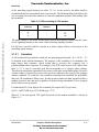
V.21 .................................................................................................................. 3-1
Establishment of connection........................................................................ 3-2
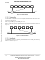
V.23 ................................................................................................................ 3-11
Contents
For More Information On This Product,
Go to: www.freescale.com
iii
Freescale Semiconductor, Inc.
Contents
Freescale Semiconductor, Inc...
Paragraph
Number
3.1.2.1
3.1.3
3.1.3.1
3.1.3.2
3.1.3.3
3.1.3.4
3.1.3.5
3.1.4
3.1.4.1
3.1.4.2
3.1.4.3
3.1.4.4
3.1.4.5
3.1.4.6
3.1.4.7
3.1.5
3.1.5.1
3.1.5.2
3.1.6
3.1.6.1
3.1.6.1.1
3.1.6.1.2
3.1.6.1.3
3.1.6.1.4
3.1.6.1.5
3.1.6.2
3.1.6.2.1
3.1.6.2.2
3.1.6.2.3
3.1.6.2.4
3.1.6.2.5
3.1.6.2.6
3.1.6.2.7
3.1.6.3
3.1.6.4
3.1.7
3.1.7.1
3.1.7.1.1
3.1.7.1.2
3.1.7.1.3
3.1.7.1.4
iv
Title
Page
Number
Establishment of connection...................................................................... 3-11
V.22 ................................................................................................................ 3-20
Scrambler................................................................................................... 3-21
Descrambler............................................................................................... 3-22
Handshake.................................................................................................. 3-22
Implementation .......................................................................................... 3-24
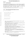
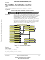
RX V.22 Handshake data handler structure ............................................... 3-24
V.22bis ........................................................................................................... 3-33
Scrambler................................................................................................... 3-34
Descrambler............................................................................................... 3-35
Handshake.................................................................................................. 3-35
Retrain sequence (2400 bit/s operation) .................................................... 3-38
Implementation .......................................................................................... 3-39
RX V.22bis handshake data handler structure ........................................... 3-39
TX V.22bis handshake data handler structure ........................................... 3-41
FSK ................................................................................................................ 3-52
FSK Transmitter ........................................................................................ 3-52
FSK Receiver............................................................................................. 3-53
DPSK ............................................................................................................. 3-64
DPSK transmitter....................................................................................... 3-64
Scrambler............................................................................................... 3-65
Encoder.................................................................................................. 3-65
Modulator .............................................................................................. 3-65
Bandpass filter ....................................................................................... 3-65
Guard tone generator ............................................................................. 3-66
DPSK receiver ........................................................................................... 3-66
Bandpass filters...................................................................................... 3-66
Automatic Gain Control (AGC) ............................................................ 3-67
Demodulator .......................................................................................... 3-67
Decision block and Decoder.................................................................. 3-67
Descrambler........................................................................................... 3-68
Clock Recovery ..................................................................................... 3-68
Carrier Recovery.................................................................................... 3-69
DPSK modulator control structure ............................................................ 3-70
DPSK demodulator control structure......................................................... 3-72
QAM .............................................................................................................. 3-80
QAM transmitter........................................................................................ 3-80
Scrambler............................................................................................... 3-81
Encoder.................................................................................................. 3-81
Modulator .............................................................................................. 3-81
Transmit filter ........................................................................................ 3-82
MCF5407 LDR Soft Modem Software Developer’s Reference Manual
For More Information On This Product,
Go to: www.freescale.com
MOTOROLA
Freescale Semiconductor, Inc.
Contents
Freescale Semiconductor, Inc...
Paragraph
Number
3.1.7.1.5
3.1.7.2
3.1.7.2.1
3.1.7.2.2
3.1.7.2.3
3.1.7.2.4
3.1.7.2.5
3.1.7.2.6
3.1.7.2.7
3.1.7.2.8
3.1.7.3
3.1.7.4
3.2
3.2.1
3.2.2
3.2.3
3.2.4
3.2.5
3.2.5.1
3.2.5.2
3.2.5.3
3.2.5.3.1
3.2.5.3.2
3.2.5.4
3.2.5.5
3.2.5.6
3.2.5.7
3.2.6
3.2.7
3.3
3.3.1
3.4
3.4.1
3.4.2
3.4.3
3.5
3.5.1
3.5.2
3.6
3.6.1
3.6.2
MOTOROLA
Title
Page
Number
Guard tone generator ............................................................................. 3-82
QAM receiver ............................................................................................ 3-82
Bandpass filters...................................................................................... 3-82
Automatic Gain Control (AGC) ............................................................ 3-83
Demodulator .......................................................................................... 3-83
Decision block and Decoder.................................................................. 3-83
Descrambler........................................................................................... 3-84
Adaptive Equalizer ................................................................................ 3-84
Clock Recovery ..................................................................................... 3-84
Carrier Recovery.................................................................................... 3-85
QAM modulator control structure ............................................................. 3-87
QAM demodulator control structure ......................................................... 3-89
V.42 Error Correction....................................................................................... 3-100
General structure of the V.42 module .......................................................... 3-102
Accessing the data buffers ........................................................................... 3-103
Timing control ............................................................................................. 3-105
Detection phase............................................................................................ 3-105
V.42 Receiver............................................................................................... 3-108
Bit-level input .......................................................................................... 3-108
FCS check................................................................................................ 3-110
Frame handler ...........................................................................................3-111
Information frame handling..................................................................3-111
Supervisor frame handling................................................................... 3-115
The V.42 Transmitter ............................................................................... 3-116
Frame capsulation and sending data ........................................................ 3-117
Sending Information frames .................................................................... 3-117
Sending Supervisor frames ...................................................................... 3-117
Support of the V.14 protocol........................................................................ 3-118
The V.42 module function description......................................................... 3-119
V.42bis Data Compression Protocol ................................................................ 3-128
Protocol Background Information ............................................................... 3-128
Implementation Overview ............................................................................... 3-130
Communication with V.42 ........................................................................... 3-131
Programming Interface ................................................................................ 3-133
Compression ratio ........................................................................................ 3-138
The V.14 Software Module .............................................................................. 3-138
V.14 Data Handler........................................................................................ 3-138
Rx V.14 Data Handler .................................................................................. 3-145
V.8 Software Module ....................................................................................... 3-152
V8 Data Handler .......................................................................................... 3-152
Rx V8 Data Handler .................................................................................... 3-158
Contents
For More Information On This Product,
Go to: www.freescale.com
v
Freescale Semiconductor, Inc.
Contents
Freescale Semiconductor, Inc...
Paragraph
Number
Title
Page
Number
3.6.3
3.6.4
3.7
3.7.1
3.7.2
3.7.3
3.7.3.1
3.7.3.2
3.7.4
3.7.5
3.7.6
3.7.7
3.8
3.8.1
3.8.2
3.8.3
The V.8 start-up procedure in calling mode................................................. 3-165
The V.8 start-up procedure in answering mode ........................................... 3-165
Support Modules.............................................................................................. 3-166
UART module.............................................................................................. 3-166
DAA Interface.............................................................................................. 3-183
Tone Generator and Detector ....................................................................... 3-199
Tone Generator ........................................................................................ 3-199
Tone Detector........................................................................................... 3-204
Ring Detector............................................................................................... 3-211
DTMF Dialer ............................................................................................... 3-213
Pulse Dialer.................................................................................................. 3-218
Text Response .............................................................................................. 3-221
Miscellaneous Functions.................................................................................. 3-229
AT command set support ............................................................................. 3-232
Command Parser.......................................................................................... 3-233
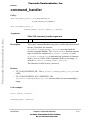
Command Handler....................................................................................... 3-241
vi
MCF5407 LDR Soft Modem Software Developer’s Reference Manual
For More Information On This Product,
Go to: www.freescale.com
MOTOROLA
Freescale Semiconductor, Inc.
Figures
Freescale Semiconductor, Inc...
Figure
Number
1-1
2-1
2-2
2-3
3-1
3-2
3-3
3-4
3-5
3-6
3-7
3-8
3-9
3-10
3-11
3-12
3-13
3-14
3-15
3-16
3-17
3-18
3-19
3-20
3-21
3-22
3-23
3-24
3-25
3-26
3-27
3-28
3-29
3-30
3-31
Title
Page
Number
Modem Daughter Card Installation. Jumper Settings................................................. 1-4
Basic Architecture of the Standalone Version of the LDR Soft Modem .................... 2-1
The Data Flow Diagram.............................................................................................. 2-3
Global State Machine................................................................................................ 2-21
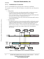
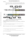
Timing diagram of the V.21 Handshake sequence...................................................... 3-2
Timing diagram of the V.23 Handshake sequence.................................................... 3-12
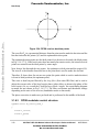
Signal Constellation for V.22 .................................................................................... 3-20
V.22 scrambler........................................................................................................... 3-22
V.22 descrambler....................................................................................................... 3-22
Handshake sequence ................................................................................................. 3-23
Handshake state diagram .......................................................................................... 3-30
V.22bis 16-point constellation diagram..................................................................... 3-34
V.22bis scrambler...................................................................................................... 3-35
V.22bis descrambler .................................................................................................. 3-35
V.22bis handshake sequence ..................................................................................... 3-36
V.22bis retrain sequence............................................................................................ 3-39
Handshake State Diagram ......................................................................................... 3-47
FSK Tx Data Pump ................................................................................................... 3-52
FSK Transmitter structure......................................................................................... 3-53
FSK Rx Data Pump................................................................................................... 3-53
FSK Demodulator structure ...................................................................................... 3-54
Simplified demodulation spectrum of a binary FSK signal ...................................... 3-55
DPSK transmitter block diagram .............................................................................. 3-65
DPSK modem receiver block diagram...................................................................... 3-66
Signal energies over a baud....................................................................................... 3-68
Clock Recovery block diagram................................................................................. 3-69
Carrier Recovery block diagram ............................................................................... 3-69
DPSK receiver decision points ................................................................................. 3-70
QAM transmitter block diagram ............................................................................... 3-81
QAM modem receiver block diagram ...................................................................... 3-82
Signal energies over a baud....................................................................................... 3-85
QAM Clock Recovery block diagram ...................................................................... 3-85
QAM Carrier Recovery block diagram..................................................................... 3-86
QAM receiver decision points .................................................................................. 3-87
External relationships of the V.42 module .............................................................. 3-100
MOTOROLA
Figures
For More Information On This Product,
Go to: www.freescale.com
vii
Freescale Semiconductor, Inc.
Figures
Freescale Semiconductor, Inc...
Figure
Number
3-32
3-33
3-34
3-35
3-36
3-37
3-38
3-39
3-40
3-41
3-42
3-43
3-44
3-45
3-46
3-47
3-48
3-49
3-50
viii
Title
Page
Number
General structure of the V.42 module ..................................................................... 3-103
State machine of the V.42 receiver.......................................................................... 3-106
State machine of the V.42 transmitter ..................................................................... 3-107
Structure of the V.42 receiver.................................................................................. 3-108
Structure of the V.42 transmitter ............................................................................. 3-116
V.42bis connection .................................................................................................. 3-128
Compression flow ................................................................................................... 3-132
Decompression flow ............................................................................................... 3-133
Tx V.14 Data Handler in the Tx channel................................................................. 3-138
Tx V.14 Data Handler ............................................................................................. 3-139
General data flow according the V.14 Recommendation........................................ 3-140
The Rx V.14 Data handler....................................................................................... 3-145
Tone generator......................................................................................................... 3-203
Tone detector........................................................................................................... 3-210
Stages of the Tone Detection................................................................................... 3-210
Ring Detector .......................................................................................................... 3-213
DTMF dialer ........................................................................................................... 3-217
Pulse dialer.............................................................................................................. 3-220
Command Handler .................................................................................................. 3-241
MCF5407 LDR Soft Modem Software Developer’s Reference Manual
For More Information On This Product,
Go to: www.freescale.com
MOTOROLA
Freescale Semiconductor, Inc.
Tables
Freescale Semiconductor, Inc...
Table
Number
i
1-1
2-1
2-2
2-3
2-4
2-5
2-6
2-7
2-8
2-9
2-10
2-11
2-12
2-13
2-14
2-15
2-16
2-17
2-18
2-19
2-20
2-21
2-22
2-23
2-24
2-25
2-26
2-27
2-28
2-29
2-30
2-31
2-32
3-1
Title
Page
Number
Acronyms and Abbreviated Terms............................................................................ xviii
Data Pump Protocols Supported by Soft Modem ....................................................... 1-1
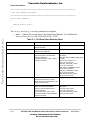
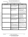
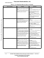
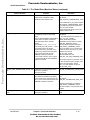
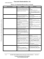
The Global State Machine States .............................................................................. 2-16
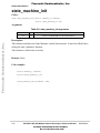
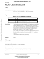
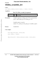
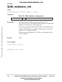
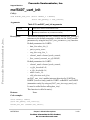
state_machine_init arguments................................................................................... 2-22
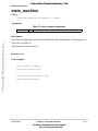
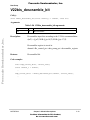
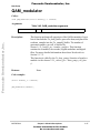
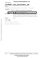
state_machine arguments .......................................................................................... 2-23
Global Data Structures ............................................................................................. 2-24
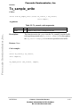
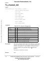
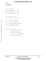
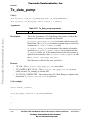
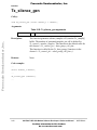
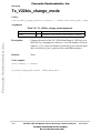
Tx_sample_write arguments ..................................................................................... 2-25
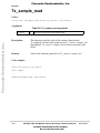
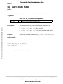
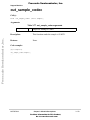
Tx_sample_read arguments ...................................................................................... 2-26
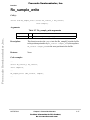
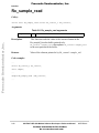
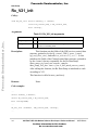
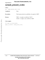
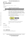
Rx_sample_write arguments..................................................................................... 2-27
Rx_sample_read arguments ...................................................................................... 2-28
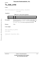
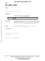
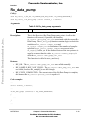
Tx_data_write arguments.......................................................................................... 2-29
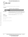
Tx_data_read arguments ........................................................................................... 2-30
Rx_data_write arguments.......................................................................................... 2-31
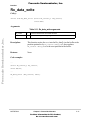
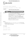
Rx_data_read arguments.......................................................................................... 2-32
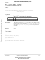
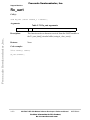
Tx_uart_data_write arguments................................................................................. 2-33
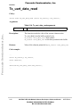
Tx_uart_data_read arguments ................................................................................... 2-34
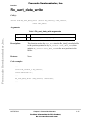
Rx_uart_data_read arguments................................................................................... 2-36
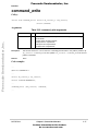
command_write arguments ....................................................................................... 2-37
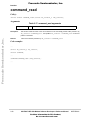
command_read arguments ........................................................................................ 2-38
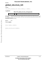
global_structure_init arguments................................................................................ 2-39
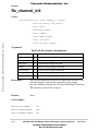
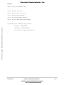
Tx_channel_init arguments....................................................................................... 2-40
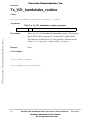
Rx_channel_init arguments....................................................................................... 2-42
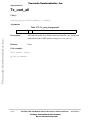
Tx_reset arguments ................................................................................................... 2-46
Rx_reset arguments................................................................................................... 2-47
Tx_data_pump arguments......................................................................................... 2-48
Rx_data_pump arguments......................................................................................... 2-49
Tx_data_handler arguments ...................................................................................... 2-50
Rx_data_handler arguments...................................................................................... 2-51
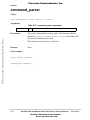
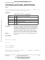
command_parser arguments...................................................................................... 2-52
command_handler arguments ................................................................................... 2-53
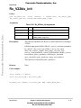
Tx_silence_gen arguments........................................................................................ 2-54
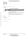
Rx_idle arguments .................................................................................................... 2-55
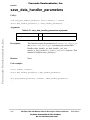
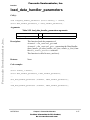
save_data_handler_parameters arguments................................................................ 2-56
load_data_handler_parameters arguments ................................................................ 2-57
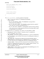
Tx_V21_init arguments .............................................................................................. 3-5
MOTOROLA
Tables
For More Information On This Product,
Go to: www.freescale.com
ix
Freescale Semiconductor, Inc.
Tables
Freescale Semiconductor, Inc...
Table
Number
3-2
3-3
3-4
3-5
3-6
3-7
3-8
3-9
3-10
3-11
3-12
3-13
3-14
3-15
3-16
3-17
3-18
3-19
3-20
3-21
3-22
3-23
3-24
3-25
3-26
3-27
3-28
3-29
3-30
3-31
3-32
3-33
3-34
3-35
3-36
3-37
3-38
3-39
3-40
3-41
3-42
x
Title
Page
Number
Rx_V21_init arguments .............................................................................................. 3-6
Tx_V21_handshake_init arguments............................................................................ 3-7
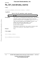
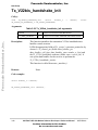
Tx_V21_handshake_routine arguments...................................................................... 3-8
Rx_V21_handshake_init arguments ........................................................................... 3-9
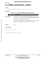
Rx_V21_handshake_routine arguments ................................................................... 3-10
Tx_V23_init arguments ............................................................................................ 3-14
Rx_V23_init arguments ............................................................................................ 3-15
Tx_V23_handshake_init arguments.......................................................................... 3-16
Tx_V23_handshake_routine arguments.................................................................... 3-17
Rx_V23_handshake_init arguments ......................................................................... 3-18
Rx_V23_handshake_routine arguments ................................................................... 3-19
Bits encoding in V.22 modem ................................................................................... 3-21
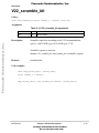
V22_scramble_bit arguments.................................................................................... 3-25
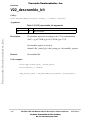
V22_descramble_bit arguments................................................................................ 3-26
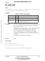
Tx_V22_init arguments ............................................................................................ 3-27
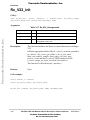
Rx_V22_init arguments ............................................................................................ 3-28
Rx_V22_handshake_init arguments ......................................................................... 3-29
Rx_V22_handshake_routine arguments ................................................................... 3-30
Tx_V22_handshake_init arguments.......................................................................... 3-31
Tx_V22_handshake_routine arguments.................................................................... 3-32
Bits encoding in V.22bis modem .............................................................................. 3-33
V22bis_scramble_bit arguments............................................................................... 3-42
V22bis_descramble_bit arguments ........................................................................... 3-43
Tx_V22bis_init arguments....................................................................................... 3-44
Rx_V22bis_init arguments....................................................................................... 3-45
Rx_V22bis_handshake_init arguments.................................................................... 3-46
Rx_V22bis_handshake_routine arguments............................................................... 3-47
Tx_V22bis_handshake_init arguments ..................................................................... 3-48
Tx_V22bis_handshake_routine arguments.............................................................. 3-49
Tx_V22bis_change_mode arguments ....................................................................... 3-50
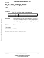
Rx_V22bis_change_mode arguments....................................................................... 3-51
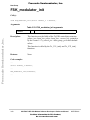
FSK_modulator_init arguments ................................................................................ 3-60
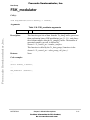
FSK_modulator arguments ....................................................................................... 3-61
FSK_demodulator_init arguments ........................................................................... 3-62
FSK_demodulator arguments.................................................................................... 3-63
DPSK_modulator_init arguments ............................................................................. 3-76
DPSK_modulator arguments .................................................................................... 3-77
DPSK_demodulator_init arguments ........................................................................ 3-78
DPSK_demodulator arguments................................................................................ 3-79
QAM_modulator_init arguments .............................................................................. 3-96
QAM_modulator arguments ..................................................................................... 3-97
MCF5407 LDR Soft Modem Software Developer’s Reference Manual
For More Information On This Product,
Go to: www.freescale.com
MOTOROLA
Freescale Semiconductor, Inc.
Tables
Freescale Semiconductor, Inc...
Table
Number
3-43
3-44
3-45
3-46
3-47
3-48
3-49
3-50
3-51
3-52
3-53
3-54
3-55
3-56
3-57
3-58
3-59
3-60
3-61
3-62
3-63
3-64
3-65
3-66
3-67
3-68
3-69
3-70
3-71
3-72
3-73
3-74
3-75
3-76
3-77
3-78
3-79
3-80
3-81
3-82
3-83
Title
Page
Number
QAM_demodulator_init arguments .......................................................................... 3-98
QAM_demodulator arguments.................................................................................. 3-99
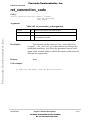
ret_connection_code arguments.............................................................................. 3-120
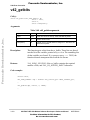
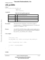
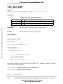
v42_getbits arguments ............................................................................................ 3-121
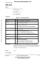
v42_init arguments.................................................................................................. 3-122
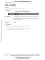
v42_putbits arguments ............................................................................................ 3-124
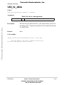
v42_rx_data arguments ........................................................................................... 3-125
v42_tx_data arguments ........................................................................................... 3-126
v42_viewbits arguments.......................................................................................... 3-127
V42bis Functions .................................................................................................... 3-133
v42bis_Init arguments............................................................................................. 3-134
v42bis_Encode arguments ...................................................................................... 3-135
v42bis_Encode arguments ..................................................................................... 3-136
v42bis_Flush arguments......................................................................................... 3-137
Compression ratio comparison................................................................................ 3-138
Tx_V14_DH_init arguments................................................................................... 3-141
Tx_V14_DH_routine arguments............................................................................. 3-142
v14_putbits arguments ............................................................................................ 3-143
Rx_V14_DH_init arguments .................................................................................. 3-147
Rx_V14_DH_routine arguments ............................................................................ 3-148
v14_getbits arguments ............................................................................................ 3-151
Tx_V8_DH_init arguments..................................................................................... 3-154
Tx_V8_DH_routine arguments............................................................................... 3-155
v8_put_bits arguments ............................................................................................ 3-157
Rx_V8_DH_init arguments .................................................................................... 3-161
Rx_V8_DH_routine arguments .............................................................................. 3-162
v8_get_bits arguments ............................................................................................ 3-164
mcf5407_uart_init arguments ................................................................................. 3-170
mcf5407_uart_parameters_set arguments............................................................... 3-171
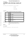
mcf5407_uart_interrupt_mask_set arguments ........................................................ 3-172
Rx_uart arguments .................................................................................................. 3-173
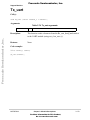
Tx_uart arguments .................................................................................................. 3-174
Tx_uart_all arguments ............................................................................................ 3-175
out_char_uart arguments......................................................................................... 3-177
out_sample_codec arguments ................................................................................. 3-180
flow_control arguments .......................................................................................... 3-182
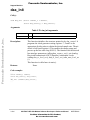
daa_init arguments .................................................................................................. 3-185
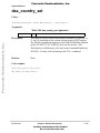
daa_country_set arguments..................................................................................... 3-186
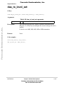
daa_rx_level_set arguments .................................................................................... 3-187
daa_tx_level_set arguments .................................................................................... 3-188
daa_aout_level_set arguments ................................................................................ 3-189
MOTOROLA
Tables
For More Information On This Product,
Go to: www.freescale.com
xi
Freescale Semiconductor, Inc.
Tables
Freescale Semiconductor, Inc...
Table
Number
3-84
3-85
3-86
3-87
3-88
3-89
3-90
3-91
3-92
3-93
3-94
3-95
3-96
3-97
3-98
3-99
3-100
3-101
3-102
3-103
3-104
3-105
3-106
3-107
3-108
3-109
3-110
3-111
3-112
3-113
3-114
3-115
3-116
3-117
3-118
3-119
3-120
3-121
3-122
3-123
3-124
xii
Title
Page
Number
daa_aout_mute arguments....................................................................................... 3-190
daa_ring_detect arguments...................................................................................... 3-191
daa_go_off_hook arguments ................................................................................... 3-192
daa_go_on_hook arguments.................................................................................... 3-193
daa_read_reg arguments.......................................................................................... 3-194
daa_write_reg arguments ........................................................................................ 3-195
Tx_daa arguments ................................................................................................... 3-196
Rx_daa arguments................................................................................................... 3-198
Tones that are supported by the Tone Generator..................................................... 3-199
Tx_tone_init arguments ......................................................................................... 3-202
Tx_tone arguments.................................................................................................. 3-203
Tones that are supported by Tone Detector............................................................. 3-204
Rx_tone_init arguments .......................................................................................... 3-209
Rx_tone arguments.................................................................................................. 3-210
Rx_ring_det_init arguments.................................................................................... 3-212
Rx_ring_detect arguments ...................................................................................... 3-213
Frequencies used by the DTMF generator .............................................................. 3-214
Tx_DTMF_init arguments ...................................................................................... 3-216
Tx_DTMF arguments.............................................................................................. 3-217
Tx_pulse_init arguments......................................................................................... 3-219
Tx_pulse arguments ................................................................................................ 3-220
Correspondence of dial digits to the number of Make/Break pulses ..................... 3-220
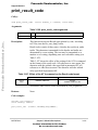
print_result_code arguments ................................................................................... 3-222
Effect of the AT V command on the Result code format........................................ 3-222
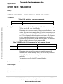
print_text_response arguments................................................................................ 3-223
Effect of AT Vn command on Text response format .............................................. 3-223
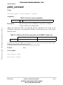
print_connect arguments ......................................................................................... 3-224
Effect of the AT Xn command on the CONNECT result code ............................... 3-224
text_to_dte arguments ............................................................................................. 3-225
text_to_dte_fixed arguments................................................................................... 3-226
char_to_dte arguments ............................................................................................ 3-227
uint8_to_str_decimal arguments ............................................................................. 3-228
uint8_to_str_hexadecimal arguments...................................................................... 3-229
dsp_cos arguments .................................................................................................. 3-230
dsp_convolution_frac arguments ............................................................................ 3-231
memcpy_mcf arguments ........................................................................................ 3-232
AT_parser_init arguments ....................................................................................... 3-235
AT_parser_init arguments ....................................................................................... 3-236
AT_parser_init arguments ....................................................................................... 3-238
AT_parser_init arguments ....................................................................................... 3-240
AT_handler_init arguments..................................................................................... 3-242
MCF5407 LDR Soft Modem Software Developer’s Reference Manual
For More Information On This Product,
Go to: www.freescale.com
MOTOROLA
Freescale Semiconductor, Inc.
Tables
Table
Number
AT_handler_routine arguments ............................................................................... 3-243
Freescale Semiconductor, Inc...
3-125
Title
Page
Number
MOTOROLA
Tables
For More Information On This Product,
Go to: www.freescale.com
xiii
Freescale Semiconductor, Inc.
Tables
Title
Page
Number
Freescale Semiconductor, Inc...
Table
Number
xiv
MCF5407 LDR Soft Modem Software Developer’s Reference Manual
For More Information On This Product,
Go to: www.freescale.com
MOTOROLA
Freescale Semiconductor, Inc.
About This Book
Freescale Semiconductor, Inc...
The primary objective of this user’s manual is to define the functionality of the MCF5407
processors for use by software developers.
The information in this book is subject to change without notice, as described in the
disclaimers on the title page of this book. As with any technical documentation, it is the
readers’ responsibility to be sure he is using the most recent version of the documentation.
To locate any published errata or updates for this document, refer to the world-wide web at
http://www.motorola.com/coldfire.
Audience
This manual is intended for system software developers who want to develop products with
the MCF5407. It is assumed that the reader understands operating systems, microprocessor
system design, basic principles of software and hardware, and basic details of the
ColdFire® architecture.
Suggested Reading
This section lists additional reading that provides background for the information in this
manual as well as general information about the ColdFire architecture.
General Information
The following documentation provides useful information about the ColdFire architecture
and computer architecture in general:
ColdFire Documentation
The ColdFire documentation is available from the sources listed on the back cover of this
manual. Document order numbers are included in parentheses for ease in ordering.
•
ColdFire Programmers Reference Manual, R1.0 (MCF5200PRM/AD)
•
ColdFire MCF5407 User’s Manual, 0.1 (MCF5407UM/AD)
•
Motorola M5407C3 User’s Manual, R1.1 (M5407C3UM/AD).
•
Silicon Laboratories Si3044 Data Sheet, R2.01 (Si3044-DS201)
MOTOROLA
About This Book
For More Information On This Product,
Go to: www.freescale.com
xv
Freescale Semiconductor, Inc.
Acronyms and Abbreviations
Acronyms and Abbreviations
Table i lists acronyms and abbreviations used in this document.
Table i. Acronyms and Abbreviated Terms
Term
AGC
Automatic Gain Control
AFE
Analogue Front End
ANS
Answer tone (see V.25)
BPF
Bandpass filter
DAA
Data Access Arrangement
Freescale Semiconductor, Inc...
DTMF
Dual Tone Multi Frequency Signaling
DCE
Data Circuit-terminating Equipment
DTE
Data Terminal Equipment
DPSK
Differential PSK
EC
Echo Canceling
FIR
Finite Impulse Response
FSK
Frequency Shift Keying
FDM
Frequency Division Multiplexing
GSTN
IIR
General Switched Telephone Network
Infinite Impulse Response
LDR
Low Data Rate
LPF
Low-pass filter
HSP
Host Signal Processing
PSK
Phase Shift Keying
PSTN
SM
QAM
QDPSK
UART
USART
xvi
Meaning
Public Switched Telephone Network
Soft Modem
Quadrature Amplitude Modulation
Quadrature DPSK
Universal asynchronous receiver / transmitter
Universal synchronous/asynchronous receiver transmitter
MCF5407 LDR Soft Modem Software Developer’s Reference Manual
For More Information On This Product,
Go to: www.freescale.com
MOTOROLA
Freescale Semiconductor, Inc.
Freescale Semiconductor, Inc...
Chapter 1
Introduction
This document describes the low data rate (LDR) Soft Modem (with data rates up to 2400
bits / second) for the MCF5407 ColdFire processor. The Soft Modem includes support for
the Data Pump in real-time software, as well as the AT command set and other protocols
(see below). The chosen development platform is the MCF5407C3 EVM, with an
additional Daughter card. The Daughter card is used to provide the Data Access
Arrangement (codec and phone line interface) such as Silicon Labs Si3044.
In this manual, you will find the information required to use and maintain the LDR Soft
Modem interfaces and algorithms.
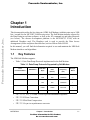
1.1
Key Features
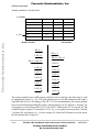
The LDR Soft Modem supports:
•
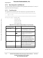
Table 1-1 lists Data Pump Protocols implemented in the Soft Modem.
Table 1-1. Data Pump Protocols Supported by Soft Modem
ITU-T
recommendation
Modulation
Data Rate
(bps)
Modulation
Rate
(bauds)
Carrier
Frequency
(Hz)
Bits per
Baud
V.22bis
QAM
2400
600
1200/2400
4
1200
600
1200/2400
2
1200
600
1200/2400
2
600
600
1200/2400
1
75/1200
75/1200
420/1700
1
75/600
75/600
420/1500
1
300
300
1080/1750
1
V.22
V.23
V.21
•
•
•
•
DPSK
FSK
FSK
ITU-T V.21, V.23, V.22 and V22bis Physical Handshake Sequences.
ITU-T V.42 Error Correction.
ITU-T V.42bis Data Compression.
ITU-T V.14 sync-to-asynchronous converter.
MOTOROLA
Chapter 1. Introduction
For More Information On This Product,
Go to: www.freescale.com
1-1
Freescale Semiconductor, Inc.
Related Files
•
•
•
•
•
1.2
AT-command set.
Tone generation and detection.
DTMF and Pulse dialing.
DAA interface (Si3044 Modem Daughter Card) via the on-chip USART module.
DTE interface via the on-chip UART module.
Related Files
The following files are relevant to the Soft Modem:
Freescale Semiconductor, Inc...
•
•
•
•
•
•
•
•
•
•
•
•
•
•
•
•
•
•
•
•
•
•
•
1-2
– entry point of the Soft Modem.
modem.h – high level functions and main data structure definitions.
modem.c – implementation of high level functions.
state_machine.h – definition of state machine data structure.
state_machine.c – implementation of main state machine.
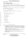
v21.h – definitions used by V.21 protocol.
v21.c – initialization of V.21 data pump protocol and realization of physical
handshake sequence for V.21.
v23.h – definitions used by V.23 protocol.
v23.c – initialization of V.23 data pump protocol and realization of physical
handshake sequence for V.23.
v22.h – definitions used by V.22 protocol.
v22.c – initialization of V.22 data pump protocol and realization of physical
handshake sequence for V.22.
v22bis.h – definitions used by V.22bis protocol.
v22bis.c – initialization of V.22bis data pump protocol and realization of physical
handshake sequence for V.22bis.
fsk.h – FSK data pump definitions.
fsk.c – realization of FSK data pump.
dpsk.h – DPSK data pump definitions.
dpsk.c – realization of 2,4-DPSK data pump.
qam.h – QAM data pump definitions.
qam.c – realization of 4,16-QAM data pump.
v14.h – definitions used by V.14 protocol.
v14.c – realization of V.14 data handler.
V42.h – definitions used by V.42 protocol.
V42.c – realization of V.42 protocol.
main.c
MCF5407 LDR Soft Modem Software Developer’s Reference Manual
For More Information On This Product,
Go to: www.freescale.com
MOTOROLA
Freescale Semiconductor, Inc.
Freescale Semiconductor, Inc...
Related Files
•
•
•
•
•
•
•
•
•
•
•
•
•
•
•
•
•
•
•
•
•
– definitions used by V.42bis protocol.
V42bis.c – realization of V.42bis protocol.
V8.h – definitions used by V.8 protocol.
V8.c – realization of V.8 protocol.
dtmf.h – DTMF dialer definitions.
dtmf.c – DTMF dialer realization.
pulse.h – pulse dialer definitions.
pulse.c – pulse dialer realization.
tone_gendet.h – definitions used by tone generator and detector.
tone_gendet.c – realization of tone generator and detector.
ring_det.h – definitions used by ring detector.
ring_det.c – realization of ring detector.
at_parser.h – definitions used by AT command parser.
at_parser.c – realization of AT command parser.
at_handler.h – definitions used by AT command handler.
at_handler.c – realization of AT command handler.
text_response.h – definitions used by text response routines according to V.25ter.
text_response.c – realization of text response routines according to V.25ter.
countries.h – definitions of country or area codes according to ITU-T T.35.
misc.h – definitions used by miscellaneous functions.
misc.c – realization of miscellaneous functions.
V42bis.h
The following files are HW and Compiler dependent parts of the Soft Modem:
•
•
•
•
•
•
•
•
•
•
•
– Soft Modem project file.
init.h – general data types and definitions. Init function prototypes.
si3044_daa.h – definitions used by the DAA (Si3044 Modem Daughter Card)
interface.
si3044_daa.c – realization of the DAA (Si3044 Modem Daughter Card) interface.
mcf5407_uart.h – definitions used by UART module routines.
mcf5407_uart.c – realization of UART module routines.
mcf5407_timer.h – definitions used by Timer module routines.
mcf5407_timer.c – realization of Timer module routines.
printf_uart.h – definitions used by printf_uart() routine.
printf_uart.c – realization of printf_uart() routine. Only for debug requirements.
mcf5407.h – MCF5407 definitions.
SoftMod.mcp
MOTOROLA
Chapter 1. Introduction
For More Information On This Product,
Go to: www.freescale.com
1-3
Freescale Semiconductor, Inc.
Quick Start
•
•
•
•
•
•
1.3
– lowest level routines for the MCF5407.
vector.s – MCF5407 vector table.
int_handlers.c – interrupt handlers.
sysinit.c – power-on reset configuration of the MCF5407.
ads_68K_mw.c – linker command file.
mwerks.h – defines constants used by the CodeWarrior Preprocessor.
mcf5407_lo.s
Quick Start
Carefully follow these steps to prepare the LDR Soft Modem for operation
Freescale Semiconductor, Inc...
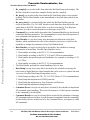
•
Properly install and set-up the Soft Modem daughter card:
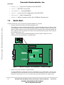
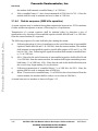
The daughter card can be installed on the M5407C3 evaluation board the wrong way. Please ensure
that the daughter card is correctly fitted before applying power. The Motorola logos on the two cards
must be read the opposite way up to each other for correct operation. When correctly installed, the
RJ11 connector will be towards the PCI socket of the main board and the speaker will be adjacent
to the DIMM memory card.
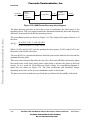
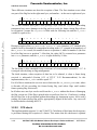
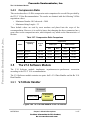
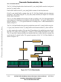
Figure 1-1 shows the correctly installed daughter card and its jumper settings for correct
communication with the M5407C3 evaluation board.
JP1
JP2 JP3
BDM
Si 3021
DO RU RW R 0 PRU )
027252/$
M5407C3 CF Modem Card
Si 3015
'LJLWDO'1$
RJ11
PCI
'LJLWDO'1$
From Motorola
027252/$
DIMM
Figure 1-1. Modem Daughter Card Installation. Jumper Settings.
•
Proper set-up of the M5407C3 evaluation board:
To setup the M5407C3 evaluation board, refer to the M5407C3 User’s Manual, R1.1. When you are
preparing the board for the first time, be sure to check that all jumpers are in the correct locations.
In practice, the locations of J21, J22, J23 and J24 are incorrect by default. The settings can be
1-4
MCF5407 LDR Soft Modem Software Developer’s Reference Manual
For More Information On This Product,
Go to: www.freescale.com
MOTOROLA
Freescale Semiconductor, Inc.
Quick Start
•
determined by allowing the board to boot up under dBUG control. Since dBUG drives the
configuration data on PP[0:3] the data will be seen on the LEDs (D1-D4). If the LED is on then the
corresponding jumper should be OFF, and if the LED is off then the jumper should be in position
2-3 (see M5407C3 User’s Manual, R1.1. Chapter 3.1.12 SDRAM DIMM ).
Use the RS-232 male/female DB-9 serial cable to connect the PC to the M5407C3.
•
Plug in the Modem daughter card to the telephone line through the RJ-11 socket (if you want to
make a connection to another modem).
•
Power-up the board.
•
Invoke the Hyper Terminal or similar terminal program on the PC to which the evaluation board is
connected and configure it to:
— Bits per second: 19200
Freescale Semiconductor, Inc...
— Data bits: 8
— Parity: none
— Stop bits: 1
— Flow control: Hardware (CTS/RTS)
•
Load ...\ SoftMod.mcp onto Metrowerks’ CodeWarrior and build the target.
•
Run project.
•
In your terminal program window you should see the Soft Modem welcome message:
=========================
LDR Soft Modem
=========================
The Soft Modem is now ready to accept your AT commands (see MCF5407 Low Data Rate Soft Modem.
AT Command reference. User Manual.)
MOTOROLA
Chapter 1. Introduction
For More Information On This Product,
Go to: www.freescale.com
1-5
Freescale Semiconductor, Inc.
Freescale Semiconductor, Inc...
Quick Start
1-6
MCF5407 LDR Soft Modem Software Developer’s Reference Manual
For More Information On This Product,
Go to: www.freescale.com
MOTOROLA
Freescale Semiconductor, Inc.
Freescale Semiconductor, Inc...
Chapter 2
General Architecture
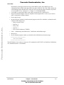
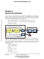
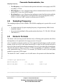
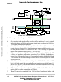
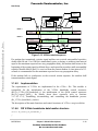
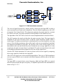
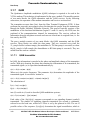
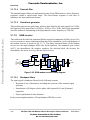
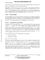
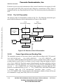
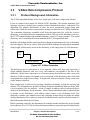
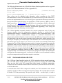
The Low Data Rate Soft Modem runs on the M5407C3 boards with an installed Modem
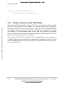
daughter card based on the Silicon Labs Si3044 DAA. The current version of the LDR Soft
Modem works as a stand-alone application without the need for an operating system (see
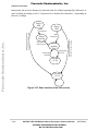
Fig 2). The two functions performed by the modem are:
•
•
Modem Data Pump functions – the modulation/demodulation functions.
Modem Control functions – error correction, hardware compression and AT
command interpretation.
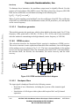
Soft Modem
Modem Daughter Card
board
Expansion
Connectors
Controller
Data pump
UART 1
RJ 11
Si3021
In Modem mode
Si3015
Pho
lin
RS -232
UART 0
Dev board M5407C3
Figure 2-1. Basic Architecture of the Standalone Version of the LDR Soft Modem
All Controller and Data Pump functionality is performed using the ColdFire MCF5407
microprocessor, with no additional DSP processor. In general the MCF5407 performs the
following functions:
•
•
•
•
•
•
Modulation/demodulation
Data encoding/decoding
Filtering
Automatic gain control
Tone dialing
Call progress monitoring
MOTOROLA
Chapter 2. General Architecture
For More Information On This Product,
Go to: www.freescale.com
2-1
Freescale Semiconductor, Inc.
•
•
•
•
•
•
AT command set interpretation
Scrambling / descrambling
Dialing
Synchronous/asynchronous conversion
Modem configuration control
Protocol initialization
Freescale Semiconductor, Inc...
The Modem Daughter Card is based on the Silicon Laboratories Si3044 Data Access
Arrangement (DAA) (combined Si3021 and Si3015 chipset shown in Fig. 2), this provides
a programmable line interface to meet global telephone line interface requirements (see
Si3044 Data Sheet, R2.01 (Si3044-DS201)).
Modem communication is a real-time process where data must be communicated in both
directions within a fixed period of time. If the modem does not meet real-time
requirements, then the modem might drop the connection. In the SM, data is sampled at
9.6KHz, so the SM must process data every 0.00010416 Seconds. The LDR Soft Modem
is capable of performing a full suite of modem functions in real-time on the MCF5407. Data
buffering is used to accommodate stress conditions. The modem accumulates a number of
samples in a buffer and processes those samples while gathering the next set of samples.
Code optimization is also important, as optimization has architectural dependencies. The
most critical parts of the source code have been rewritten in assembler, taking into account
the abilities of the MCF5407 (especially the MAC module). These assembly
implementations also include a C interface. To enable the optimized assembler source code,
it is required to define USE_OPTIMIZED_ASSEMBLER_CODE (By default this is
defined in “init.h”).
The most important benefit of using the SM is the ability to upgrade the modem purely via
software. Upgrades are typically provided to add new features, fix bugs or enhance modem
performance.
The features of the LDR Soft Modem architecture are:
•
•
•
•
•
2-2
Flexible addition of new Data Pump and Data Handler protocols with minimum
modification required to the current source code.
There is a potential for use in multi-channel systems.
The data interface between the Soft Modem modules uses a set of Circular Buffers.
It is better to implement circular buffers for the interface. This approach insulates
the modem blocks running at different synchronous and asynchronous rates.
There is a well-defined division of data processing between the Data Pump, the Data
Handler, and others modules of the Soft Modem.
Separate modules can work synchronously by detecting the level to which the
Circular Buffers are filled.
MCF5407 LDR Soft Modem Software Developer’s Reference Manual
For More Information On This Product,
Go to: www.freescale.com
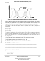
MOTOROLA
Freescale Semiconductor, Inc.
The Basic Blocks of the Soft Modem
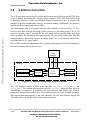
2.1
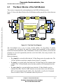
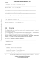
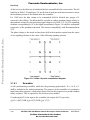
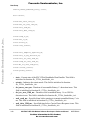
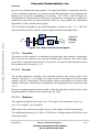
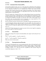
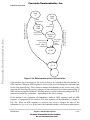
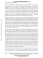
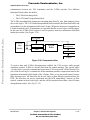
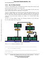
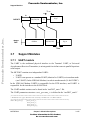
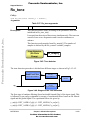
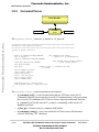
The Basic Blocks of the Soft Modem
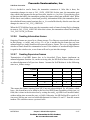
This section is important for understanding how the LDR Soft Modem works.
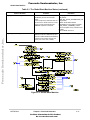
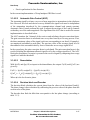
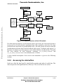
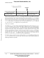
Figure 2-2 shows the Basic Blocks of the Soft Modem and the general flow of data between
them.
Rx_uart_data[]
Rx_data[]
Rx Data
Pump
Rx_sample[]
Text
Response
Tx UART0
Freescale Semiconductor, Inc...
Rx Data
Handler
Rx UART1
Control behavior of the Soft Modem
Tx UART
Interface
Rx DAA
Interface
Phone
Line
DAA
State Machine
RS-232
DAA
Control
Interface
Rx UART
Interface
Command
Handler
Rx UART0
Command
Parser
Tx_uart_data[]
Tx Data
Handler
Tx DAA
Interface
Si3044
Tx UART1
command[]
Tx_data[]
Tx Data
Pump
Tx_sample[]
S/W
Process
Cyclic buffer
H/W
Module
Figure 2-2. The Data Flow Diagram
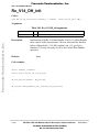
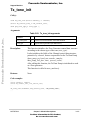
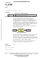
The Soft Modem uses a set of seven circular buffers, Tx_uart_data[], Tx_data[],
Tx_sample[], Rx_uart_data[], Rx_data[], Rx_sample[] and command[], as data interfaces
between the functional blocks of the Soft Modem. Circular in this instance, means that the
elements are accessed sequentially until the end of the buffer, then wrap around to the
beginning again.
Block descriptions:
•
•
•
Tx_sample[] is a circular buffer that the Tx Data Pump writes the samples into. The
Tx DAA Interface reads these samples directly from Tx_sample[].
Tx_data[] is a circular buffer from which the Tx Data Pump gets the transmit data
symbols. The Tx Data Handler writes the data symbols to be transmitted into this
buffer.
Tx_uart_data[] is a circular buffer from which the Tx Data Handler gets the
transmit data chars. The Rx UART Interface writes data chars received from the
DTE to be transmitted into this buffer. Also, this buffer is read by the Command
Parser in order to detect AT commands entered by the user.
MOTOROLA
Chapter 2. General Architecture
For More Information On This Product,
Go to: www.freescale.com
2-3
Freescale Semiconductor, Inc.
The Basic Blocks of the Soft Modem
•
•
•
Freescale Semiconductor, Inc...
•
•
•
•
•
•
•
2-4
Rx_sample[] is a circular buffer from which the Rx Data Pump reads samples. The
Rx DAA Interface writes these samples directly into Rx_sample[].
Rx_data[] is a circular buffer into which the Rx Data Pump places received data
symbols. The Rx Data Handler reads demodulated or detected data symbols from
this buffer.
Rx_uart_data[] is a circular buffer into which the Rx Data Handler puts the
received data chars. The Tx UART Interface reads data chars from this buffer and
sends them to the DTE. Also this buffer is used to write data by Text Response
functions, in order to send informative text messages to the DTE.
Command[] is a circular buffer from which the Command Handler gets the detected
commands and their parameters. The Command Parser writes detected sequences of
user commands with parameters into this buffer.
State Machine is a top-level entity that determines the behaviour of the Soft
Modem, which implements the role of the scheduler (supervisor). And it has the
capability to change the parameters of any Soft Modem block.
Data Handler is a top-level entity that is invoked by the scheduler to manage
transmission of actual data. Possible Data Handlers can be:
1. Data handler according to the ITU-T V.14 recommendation.
2. Data handler according to the ITU-T V.42 and V.42bis recommendation.
3. Data handler that performs physical handshake, for example, according to V.22
or V.22bis.
4. Data handler according to the ITU-T V.8 recommendation.
The Data Handler performs the actual handling of bits of data.
Data Pump is a top-level entity that is invoked by the scheduler to manage the
conversion of digital data into signal samples that can be sent over a phone line and
vice versa. Possible Data Pump arrangements can be:
1. Data Pump according to the ITU-T V.21/V.22/V.22bis or V.23 recommendations.
2. Data Pump that implements a DTMF generator.
3. Data Pump that implements a Tone Generator and Detector.
4. Data Pump that implements Ring detection.
Command Parser is a top-level entity that is invoked by the scheduler to implement
AT command syntax handling. This writes all sequences of valid system commands
to the command[] circular buffer.
Command Handler is a top-level entity that is invoked by the scheduler to interpret
AT commands and execute them. It reads formatted commands from the command[]
circular buffer, that are written into it by the Command Parser, in response to valid
AT commands.
MCF5407 LDR Soft Modem Software Developer’s Reference Manual
For More Information On This Product,
Go to: www.freescale.com
MOTOROLA
Freescale Semiconductor, Inc.
Sampling Frequency
•
•
•
Freescale Semiconductor, Inc...
2.2
Text Response is a set of functions that perform informative messaging to the DTE
according to V.25ter.
DTE Interface is a set of functions that perform communication between the DCE
and the DTE. It uses the UART0 module.
DAA Interface is a set of functions that implement control and interaction with the
Modem Daughter card based on an integrated direct access arrangement (DAA)
Si3044. It uses the UART1 module in modem mode (USART).
Sampling Frequency
The sampling frequency used is 9600Hz. The 9600Hz sampling rate is practical for several
reasons:
•
•
2.3
It is higher than the Nyquist sampling frequency of approximately 8KHz for the
telephone channel.
It is a convenient multiple of the popular modem baud rates (75, 300, 600, 1200 and
2400 baud etc.)
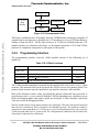
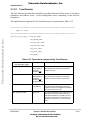
Numeric Formats
The Source code uses integer math functions only, no floating-point operation; this allows
the algorithms to be optimized to the target processor for speed.
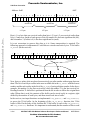
A lot of variables used in the modem are 16 bit signed fractional integers in Q14 and Q15
formats. In the case of Q14, this means that the msb is a sign bit, the bit before the msb is
to the left of the decimal point and the remaining 14 bits are to the right of the decimal point.
Therefore the numeric range is –32768 to +32767 corresponding to -2.000000 to 1.999939,
with a quantization step of 1/32768. For example, Q14 format is used by the data pump
modules to represent a PCM signal.
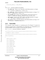
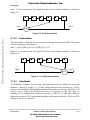
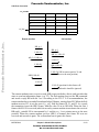
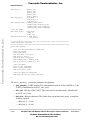
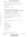
The header file “init.h” contains a set of useful macros for operation with fractional data:
...
//Samples type representation
#define COS_BITS
(14)
//Q14
#define COS_BASE
(1 << COS_BITS)
//One in Q14
...
/**********************************************************************
MOTOROLA
Chapter 2. General Architecture
For More Information On This Product,
Go to: www.freescale.com
2-5
Freescale Semiconductor, Inc.
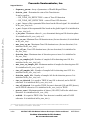
Channel
* Conversion from float to fractional type Q14
**********************************************************************/
#define CFF(x) (int16)((x)*COS_BASE)
/**********************************************************************
* Get fractional multiplication of Q14
**********************************************************************/
Freescale Semiconductor, Inc...
#define MULT_FRAC(x,y) (((x)*(y))>>COS_BITS)
/**********************************************************************
* Get fractional division of Q14
**********************************************************************/
#define DIV_FRAC(x,y) (((x)<<COS_BITS)/(y))
...
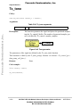
2.4
Channel
The Channel is the main control data structure, and is a mandatory parameter for most of
the Soft Modem functions.
It is actually a union of the control structures that contains pointers to the Transmitter,
Receiver, DTE and DAA control structures associated with this Channel.
In other words, the Channel is the root of the Soft Modem. Through the Channel data
structure, it is possible to get any current parameter of the Soft Modem.
The
channel_t
structure is defined in “modem.h” :
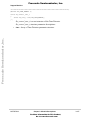
/**********************************************************************
* Channel Structure
***********************************************************************/
struct channel_t
{
struct Tx_control_t *Tx_control_ptr;
struct Rx_control_t *Rx_control_ptr;
struct state_machine_t * state_machine_ptr;
struct uart_params_t * uart_control;
2-6
MCF5407 LDR Soft Modem Software Developer’s Reference Manual
For More Information On This Product,
Go to: www.freescale.com
MOTOROLA
Freescale Semiconductor, Inc.
Channel
struct daa_control_t * daa_control;
};
The channel_t structure parameter descriptions:
•
Tx_control_ptr - Pointer to the Transmitter control data structure (see chapter
2.4.1. Transmitter). Initialized in Tx_channel_init().
Rx_control_ptr - Pointer to the Receiver control data structure (see chapter 2.4.2.
Receiver). Initialized in Rx_channel_init().
state_machine_ptr - Pointer to the State Machine control data structure (see
chapter 2.5. Global State Machine). Initialized in state_machine_init( ).
uart_control - Pointer to the UART module control data structure (see chapter
3.6.1. UART module). Initialized in mcf5407_uart_init ( ).
daa_control - Pointer to the DAA Interface control data structure (see chapter 3.6.2.
DAA Interface). ). Initialized in daa_init ( ).
•
•
Freescale Semiconductor, Inc...
•
•
2.4.1
Transmitter
The Transmitter control structure is a constituent part of the Channel. It contains the
parameters required for the Tx Data Handler, the Tx Data Pump, the Command Parser, the
Command Handler and the transmitter circular data buffer operation.
The
Tx_control_t
structure is defined in “modem.h” :
/**********************************************************************
* Transmitter control Structure
***********************************************************************/
struct Tx_control_t
{
enum Tx_state_t state;
int16 *sample_ptr;
int16 *sample_head;
int16 *sample_tail;
int16 *sample_end;
uint32 sample_length;
uint8 *data_ptr;
uint8 *data_head;
uint8 *data_tail;
uint8 *data_end;
MOTOROLA
Chapter 2. General Architecture
For More Information On This Product,
Go to: www.freescale.com
2-7
Freescale Semiconductor, Inc.
Channel
uint32 data_length;
uint8 *uart_data_ptr;
uint8 *uart_data_head;
uint8 *uart_data_tail;
uint8 *uart_data_end;
uint32 uart_data_length;
uint32 *command_ptr;
uint32 *command_head;
Freescale Semiconductor, Inc...
uint32 *command_tail;
uint32 *command_end;
uint32 command_length;
void * data_pump_ptr;
call_func_t data_pump_call_func;
uint32 number_samples;
uint8 n_bits;
uint8 n_bits_mask;
uint32 baud_rate;
uint32 process_count;
void * data_handler_ptr;
call_func_t data_handler_call_func;
enum Tx_DH_state_t data_handler_state;
uint32 number_n_bits;
void * command_parser_ptr;
call_func_t command_parser_call_func;
call_func_t command_handler_call_func;
};
The Tx_control_t structure parameter descriptions:
•
•
2-8
state - State identifier. It contains the current state of the transmitter. It is initialized
in Tx_channel_init() to TX_SILENCE_STATE.
sample_ptr - Pointer to the Tx_sample[] circular buffer. Users should not modify
this pointer. It is initialized in Tx_channel_init() to the start of Tx_sample[].
MCF5407 LDR Soft Modem Software Developer’s Reference Manual
For More Information On This Product,
Go to: www.freescale.com
MOTOROLA
Freescale Semiconductor, Inc.
Channel
•
•
•
Freescale Semiconductor, Inc...
•
•
•
•
•
•
•
•
•
•
sample_head - The Tx_sample[] circular buffer write pointer. The Data Pump
modules modify this pointer when writing their samples into Tx_sample[]. It is
initialized in Tx_channel_init() to the start of Tx_sample[].
sample_tail - The Tx_sample[] circular buffer read pointer. The Tx DAA Interface
modifies this pointer when reading samples from Tx_sample[]. The Data Pump
modules don’t modify this pointer. It is initialized in Tx_channel_init() to the start
of Tx_sample[].
sample_end - Pointer to the end of the Tx_sample[] circular buffer. Users should not
modify this pointer. It is initialized in Tx_channel_init() to the end of Tx_sample[].
sample_length - Length of the Tx_sample[] circular buffer. Initialized in
Tx_channel_init(). The user must ensure that the sample_length is large enough to
hold all of the samples generated per call as specified by the value of
number_samples.
data_ptr - Pointer to the Tx_data[] circular buffer. Users should not modify this
pointer. It is initialized in Tx_channel_init() to the start of Tx_data[].
data_head - The Tx_data[] circular buffer write pointer. The Data Handler modules
modify this pointer when writing symbols to Tx_data[]. It is initialized in
Tx_channel_init() to the start of Tx_data[].
data_tail - The Tx_data[] circular buffer read pointer. The Data Pump modules
modify this pointer when reading symbols from Tx_data[] for modulation. It is
initialized in Tx_channel_init() to the start of Tx_data[].
data_end - Pointer to the end of the Tx_data[] circular buffer. Users should not
modify this pointer. It is initialized in Tx_channel_init() to the end of Tx_data[].
data_length - Length of the Tx_data[] circular buffer. Initialized in
Tx_channel_init(). Users must ensure that the data_length is large enough to hold
all of the symbols that will be modulated by the current Data Pump.
uart_data_ptr - Pointer to the Tx_uart_data[] circular buffer. Users should not
modify this pointer. It is initialized in Tx_channel_init() to the start of
Tx_uart_data[].
uart_data_head - The Tx_uart_data[] circular buffer write pointer. The UART
interface modifies this pointer when writing characters into Tx_uart_data[]. It is
initialized in Tx_channel_init() to the start of Tx_uart_data[].
uart_data_tail - The Tx_uart_data[] circular buffer read pointer. The Data Handler
or Command Parser modifies this pointer when reading characters from
Tx_uart_data[] for further processing. It is initialized in Tx_channel_init() to the
start of Tx_uart_data[].
uart_data_end - Pointer to the end of the Tx_uart_data[] circular buffer. Users
should not modify this pointer. It is initialized in Tx_channel_init() to the end of
Tx_uart_data[].
MOTOROLA
Chapter 2. General Architecture
For More Information On This Product,
Go to: www.freescale.com
2-9
Freescale Semiconductor, Inc.
Channel
•
•
•
Freescale Semiconductor, Inc...
•
•
•
•
•
•
•
•
•
•
•
2-10
uart_data_length - Length of the Tx_uart_data[] circular buffer. Initialized in
Tx_channel_init().
command_ptr - Pointer to the command[] circular buffer. Users should not modify
this pointer. It is initialized in Tx_channel_init() to the start of command[].
command_head - The command[] circular buffer write pointer. The Command
Parser modifies this pointer when writing detected sequences of user commands
with parameters to the command[]. It is initialized in Tx_channel_init() to the start
of command[].
command_tail - The command[] circular buffer read pointer. The Command
Handler module modifies this pointer when reading commands and parameters from
command[] for further execution. It is initialized in Tx_channel_init() to the start of
command[].
command_end - Pointer to the end of the command[] circular buffer. Users should
not modify this pointer. It is initialized in Tx_channel_init() to the end of
command[].
command_length - Length of the command[] circular buffer. Initialized in
Tx_channel_init().
data_pump_ptr - Pointer to the current Tx Data Pump control structure. Every Tx
Data Pump module can have its own control data structure. It is initialized in
Tx_channel_init() to NULL.
data_pump_call_func - Pointer to the function call associated with the current Tx
Data Pump. The Tx_data_pump() function simply calls whatever function this
pointer is pointing to. It is initialized in Tx_channel_init() to Tx_silence_gen()
(Generates silence).
number_samples - Specifies the number of samples generated by Tx_sample[] per
call to the Tx_data_pump(). It is initialized in Tx_channel_init() to
DEFAULT_NUMBER_SAMPLES (defined in “modem.h”).
n_bits - Number of bits per symbol for the current modulator. It is initialized in
Tx_channel_init() to 1.
n_bits_mask - Bit mask corresponding to (1<< n_bits)-1. Can be used to mask for
valid bits when converting to symbols for Tx_data[]. It is initialized in
Tx_channel_init() to 1.
baud_rate - Modulator baud rate. It is initialized in Tx_channel_init() to 0.
process_count - Specifies the maximum number of modulator specific operations
for completion of the current state. For example, the DTMF generator uses it as a
number of modulated digits. It is initialized in Tx_channel_init() to -1.
data_handler_ptr - Pointer to the current Tx Data Handler control structure. Every
Tx Data Handler module can have its own control structure. It is initialized in
Tx_channel_init() to NULL.
MCF5407 LDR Soft Modem Software Developer’s Reference Manual
For More Information On This Product,
Go to: www.freescale.com
MOTOROLA
Freescale Semiconductor, Inc.
Channel
•
•
•
•
Freescale Semiconductor, Inc...
•
•
2.4.2
data_handler_call_func - Pointer to the function call associated with the current
Tx Data Handler. The Tx_data_handler() function simply calls whatever function
this pointer is pointing to. It is initialized in Tx_channel_init() to NULL.
data_handler_state - Current Tx Data Handler state identifier. It is initialized in
Tx_channel_init() to TX_DH_STATE_NORMAL.
number_n_bits - Number of elements that should be generated in Tx_data[] per call
to Tx_data_handler(). It is initialized in Tx_channel_init() to
DEFAULT_NUMBER_NBITS (defined in “modem.h”).
command_parser_ptr - Pointer to the current Command Parser control data
structure. It is initialized in Tx_channel_init() to NULL.
command_parser_call_func - Pointer to the function call associated with the
current Command Parser. The command_parser() function simply calls whatever
function this pointer is pointing to. It is initialized in Tx_channel_init() to NULL.
command_handler_call_func - Pointer to the function call associated with the
current Command Handler. The command_handler() function simply calls whatever
function this pointer is pointing to. It is initialized in Tx_channel_init() to NULL.
Receiver
The Receiver control structure is a constituent part of the Channel. It contains the
parameters required for the Rx Data Handler, the Rx Data Pump and the receiver circular
data buffer operation.
The Rx_control_t structure is defined in “modem.h”
/**********************************************************************
* Receiver control Structure
***********************************************************************/
struct Rx_control_t
{
enum Rx_state_t state;
int16 *sample_ptr;
int16 *sample_head;
int16 *sample_tail;
int16 *sample_end;
uint32 sample_length;
uint8 *data_ptr;
uint8 *data_head;
MOTOROLA
Chapter 2. General Architecture
For More Information On This Product,
Go to: www.freescale.com
2-11
Freescale Semiconductor, Inc.
Channel
uint8 *data_tail;
uint8 *data_end;
uint32 data_length;
uint8 *uart_data_ptr;
uint8 *uart_data_head;
uint8 *uart_data_tail;
uint8 *uart_data_end;
uint32 uart_data_length;
Freescale Semiconductor, Inc...
void * data_pump_ptr;
call_func_t data_pump_call_func;
uint32 number_samples;
uint8 n_bits;
uint8 n_bits_mask;
uint32 baud_rate;
uint32 process_count;
void * data_handler_ptr;
call_func_t data_handler_call_func;
enum Rx_DH_state_t data_handler_state;
uint32 number_n_bits;
uint32 connection_code;
};
The Tx_control_t structure parameter descriptions:
•
•
•
•
2-12
state - State identifier. It contains the current state of the receiver. It is initialized in
Rx_channel_init() to RX_IDLE_STATE.
sample_ptr - Pointer to the Rx_sample[] circular buffer. Users should not modify
this pointer. It is initialized in Rx_channel_init() to the start of Rx_sample[].
sample_head - The Rx_sample[] circular buffer write pointer. The Rx DAA
Interface modifies this pointer when writing the samples into Rx_sample[]. It is
initialized in Rx_channel_init() to the start of Rx_sample[].
sample_tail - The Rx_sample[] circular buffer read pointer. The Rx Data Pump
modules modify this pointer when reading samples from Rx_sample[]. It is
initialized in Rx_channel_init() to the start of Rx_sample[].
MCF5407 LDR Soft Modem Software Developer’s Reference Manual
For More Information On This Product,
Go to: www.freescale.com
MOTOROLA
Freescale Semiconductor, Inc.
Channel
•
•
•
•
Freescale Semiconductor, Inc...
•
•
•
•
•
•
•
•
•
•
sample_end - Pointer to the end of the Rx_sample[] circular buffer. Users should
not modify this pointer. It is initialized in Rx_channel_init() to the end of
Rx_sample[].
sample_length - Length of the Rx_sample[] circular buffer. Initialized in
Rx_channel_init().
data_ptr - Pointer to the Rx_data[] circular buffer. Users should not modify this
pointer. It is initialized in Rx_channel_init() to the start of Rx_data[].
data_head - The Rx_data[] circular buffer write pointer. The Data Pump modules
modify this pointer when writing symbols into Rx_data[]. It is initialized in
Rx_channel_init() to the start of Rx_data[].
data_tail - The Rx_data[] circular buffer read pointer. The Data Handler modules
modify this pointer when reading symbols from Rx_data[] for further processing. It
is initialized in Rx_channel_init() to the start of Rx_data[].
data_end - Pointer to the end of the Rx_data[] circular buffer. Users should not
modify this pointer. It is initialized in Rx_channel_init() to the end of Rx_data[].
data_length - Length of the Rx_data[] circular buffer. Initialized in
Rx_channel_init(). Users must ensure that the data_length is large enough to hold
all of the symbols that will be demodulated by the current Data Pump.
uart_data_ptr - Pointer to the Rx_uart_data[] circular buffer. Users should not
modify this pointer. It is initialized in Rx_channel_init() to the start of
Rx_uart_data[].
uart_data_head - The Rx_uart_data[] circular buffer write pointer. The Data
Handler modules modify this pointer when writing characters into Rx_uart_data[].
It is initialized in Rx_channel_init() to the start of Rx_uart_data[].
uart_data_tail - The Rx_uart_data[] circular buffer read pointer. The UART
Interface modifies this pointer when reading characters from Rx_uart_data[] for
sending to the DTE. It is initialized in Rx_channel_init() to the start of
Rx_uart_data[].
uart_data_end - Pointer to the end of the Rx_uart_data[] circular buffer. Users
should not modify this pointer. It is initialized in Rx_channel_init() to the end of
Rx_uart_data[].
uart_data_length - Length of the Rx_uart_data[] circular buffer. Initialized in
Rx_channel_init().
data_pump_ptr - Pointer to the current Rx Data Pump control structure. Every
Data Pump module can have its own control data structure. Initialized in
Rx_channel_init() to NULL.
data_pump_call_func - Pointer to the function call associated with the current Rx
Data Pump. The Rx_data_pump() function simply calls whatever function this
MOTOROLA
Chapter 2. General Architecture
For More Information On This Product,
Go to: www.freescale.com
2-13
Freescale Semiconductor, Inc.
Global State Machine
•
•
Freescale Semiconductor, Inc...
•
•
•
•
•
•
•
•
2.5
pointer is pointing to. It is initialized in Rx_channel_init() to Rx_idle() (Discards
samples from the Rx_sample[] ).
number_samples - Specifies the number of samples that should be in Rx_sample[]
before an Rx_data_pump() call. It is initialized in Rx_channel_init() to
DEFAULT_NUMBER_SAMPLES (defined in “modem.h”).
n_bits - Number of bits per symbol for the current demodulator. Initialized in
Rx_channel_init() to 1.
n_bits_mask - Bit mask corresponding to (1<< n_bits)-1. Can be used to mask for
valid bits when converting to symbols from Rx_data[]. Initialized in
Rx_channel_init() to 1.
baud_rate - Demodulator baud rate. It is initialized in Rx_channel_init() to 0.
process_count - Specifies the maximum number of demodulator specific operations
for completion of the current state. For example, Ring detector uses it as number of
Ring cadence to be detected. It is initialized in Rx_channel_init() to -1.
data_handler_ptr - Pointer to current Rx Data Handler control structure. Every Rx
Data Handler module can have its own control structure. It is initialized in
Rx_channel_init() to NULL.
data_handler_call_func - Pointer to the function call associated with the current
Rx Data Handler. The Rx_data_handler() function simply calls whatever function
this pointer is pointing to. It is initialized in Rx_channel_init() to NULL.
data_handler_state - Current Rx Data Handler state identifier. It is initialized in
Rx_channel_init() to RX_DH_STATE_NORMAL.
number_n_bits - Specifies the number of elements that should be in Rx_data[]
before a data_handler_call_func() call. It is initialized in Rx_channel_init() to
DEFAULT_NUMBER_NBITS (defined in “modem.h”).
connection_code - Contains two connection responses used for printing to the DTE
after the Handshake is complete. The Data Handler module modifies this value after
protocol handshake completion. It is initialized in Rx_channel_init() to 0.
Global State Machine
The Global State Machine determines the behavior of the Soft Modem. It implements the
role of the scheduler (supervisor). The State Machine is responsible for proper initialization
and calling of the Data Pump, the Data Handler, the Command Parser and Command
Handler and other blocks according to the Soft Modem settings.
The description of the Global State Machine states can be found in Table 2.5. The graphical
representation of it is represented in Fig 2.5.
The
2-14
state_machine_t structure is defined in “state_machine.h” :
MCF5407 LDR Soft Modem Software Developer’s Reference Manual
For More Information On This Product,
Go to: www.freescale.com
MOTOROLA
Freescale Semiconductor, Inc.
Global State Machine
/************************************************************************
* States of the Global State Machine
************************************************************************/
enum sm_state_t {SM_INITIALIZATION_STATE,
SM_RESET_COMMAND_STATE,
SM_COMMAND_STATE,
SM_INIT_ON_LINE_COMMAND_STATE,
SM_ON_LINE_COMMAND_STATE,
Freescale Semiconductor, Inc...
SM_INIT_ON_LINE_STATE,
SM_ON_LINE_STATE,
SM_INIT_PRE_DIAL_STATE,
SM_PRE_DIAL_PAUSE_STATE,
SM_DIALTONE_DET_STATE,
SM_INIT_DIALING_STATE,
SM_DIALING_STATE,
SM_PRE_PHISICAL_HANDSHAKING_STATE,
SM_PHISICAL_HANDSHAKING_STATE,
SM_PROTOCOL_HANDSHAKING_STATE,
SM_INIT_RETRAIN_STATE,
SM_RETRAIN_STATE,
SM_INIT_PRE_ANSWERTONE_PAUSE_STATE,
SM_PRE_ANSWERTONE_PAUSE_STATE,
SM_INIT_AFTER_ANSWERTONE_PAUSE_STATE,
SM_AFTER_ANSWERTONE_PAUSE_STATE,
SM_INIT_ANSWERTONE_GEN_STATE,
SM_ANSWERTONE_GEN_STATE,
SM_INIT_ANSWERTONE_DET_STATE,
SM_ANSWERTONE_DET_STATE,
SM_INIT_V8_HANDSHAKING_STATE,
SM_V8_HANDSHAKING_STATE,
SM_INIT_LOOPBACK_STATE};
MOTOROLA
Chapter 2. General Architecture
For More Information On This Product,
Go to: www.freescale.com
2-15
Freescale Semiconductor, Inc.
Global State Machine
/************************************************************************
* The State Machine Structure
*************************************************************************/
struct state_machine_t
{
enum sm_state_t state;
};
The state_machine_t structure parameter descriptions:
Freescale Semiconductor, Inc...
•
state - Contains the current state of the Global State Machine. It is initialized in
state_machine_init () to SM_INITIALIZATION_STATE.
Table 2-1. The Global State Machine States
Name of the State
Activities
Exit States
SM_INITIALIZATION_STATE
Initialises the Command Parser and the
Command Handler.
SM_RESET_COMMAND_STATE
Resets the Receiver and the Transmitter. SM_COMMAND_STATE
Initialises the Ring Detector.
SM_COMMAND_STATE
Calls the Command Parser, the
Command Handler and the Rx Data
Pump (Ring Detector).
If a Ring is detected, it sends a “RING”
response to the DTE.
SM_INIT_ON_LINE_COMMAND_STATE
Sends an “OK” response to the DTE.
SM_ON_LINE_COMMAND_STATE
Sets the mode of the Rx & Tx Data
Handler and the Command Parser to the
“Online command mode”.
SM_ON_LINE_COMMAND_STATE
Calls the Tx & Rx Data Pumps.
Calls the Tx & Rx Data Handlers.
Calls the Command Parser and the
Command Handler.
On the “break of line” event, it goes
on-hook and sends the “NO CARRIER”
response to the DTE.
2-16
SM_RESET_COMMAND_STATE
1)SM_COMMAND_STATE :
• By default.
2)SM_INIT_PRE_ANSWERTONE_PAUS
E_STATE:
• If S0 is less or equal to S1.
• On an AT A command.
3)SM_INIT_PRE_DIAL_STATE:
• On an AT D command.
4)SM_RESET_COMMAND_STATE:
• On an AT H command.
5)SM_INIT_LOOPBACK_STATE:
• On an AT &T command.
6)SM_INITIALIZATION_STATE:
• On an AT Z command.
1)SM_ON_LINE_COMMAND_STATE:
• By default.
2) SM_ON_LINE_STATE:
• On an AT O command.
3)SM_INITIALIZATION_STATE:
• On an AT Z command.
MCF5407 LDR Soft Modem Software Developer’s Reference Manual
For More Information On This Product,
Go to: www.freescale.com
MOTOROLA
Freescale Semiconductor, Inc.
Global State Machine
Table 2-1. The Global State Machine States (continued)
Freescale Semiconductor, Inc...
Name of the State
Activities
Exit States
SM_INIT_ON_LINE_STATE
Initialises the Rx & Tx Data Pumps, and
the Rx & Tx Data Handlers (Handshaker)
according to the chosen protocol and
speed (V.21, V.23, V.22, V.22bis)
1)SM_PRE_PHISICAL_HANDSHAKING_
STATE:
• If the Channel is in the calling mode.
2)SM_PHISICAL_HANDSHAKING_STAT
E:
• If the Channel is in the answering mode.
SM_ON_LINE_STATE
Calls the Tx & Rx Data Pumps.
Calls the Tx & Rx Data Handlers.
Calls the Command Parser for the
Escape Sequence detection.
On the “break of line” event, it goes
on-hook.
1)SM_ON_LINE_STATE:
• By default.
2)SM_INIT_RETRAIN_STATE:
• On Retrain sequence detection.
3)SM_RESET_COMMAND_STATE:
• On the Break of the line.
4)SM_INIT_ON_LINE_COMMAND_STAT
E:
• If the Escape sequence is detected and
the “Go to On-line command mode on
escape code” is set in the S18 register.
SM_INIT_PRE_DIAL_STATE
If AT X2 or X4 is set, it initialises the Tone
Detector as the Dial tone detector,
otherwise (No Dial tone detection or Blind
Dialing) it initialises the Tone Generator
as the Silence tone generator.
And it goes off-hook.
1)SM_PRE_DIAL_PAUSE_STATE:
• If AT X0 was set before.
• If AT X1 was set before.
• If AT X3 was set before.
2)SM_DIALTONE_DET_STATE:
• If AT X2 was set before.
• If AT X4 was set before.
SM_PRE_DIAL_PAUSE_STATE
Calls the Rx Data Pump (Idle mode) and
the Tx Data Pump (Silence Generator).
On receipt of any character from the DTE,
it goes on-hook and sends the “NO
CARRIER” response to the DTE.
1)SM_PRE_DIAL_PAUSE_STATE:
• By default.
2)SM_INIT_DIALING_STATE:
• On the completion of the Silence
Generation.
3)SM_RESET_COMMAND_STATE:
• On the reception of any character from
the DTE.
SM_DIALTONE_DET_STATE
Calls the Tx Data Pump (Silence
generator) and the Rx Data Pump (Dial
Tone Detector).
On the receipt of any character from the
DTE, it goes on-hook and sends the “NO
CARRIER” response to the DTE.
If the Dial Tone was not detected during a
fixed period of time, it goes on-hook and
sends the “NO DIAL TONE” response to
the DTE.
1)SM_DIALTONE_DET_STATE:
• By default.
2)SM_INIT_DIALING_STATE:
• If the Dial Tone is detected during a fixed
time.
3)SM_RESET_COMMAND_STATE:
• On the reception of any character from
the DTE.
• If the Dial Tone is not detected during a
fixed period of time.
SM_INIT_DIALING_STATE
Fills the Tx_data[] buffer with dial digits.
initializes the DTMF dialer or the Pulse
dialer (if Pulse dialing is enabled in the
S[13] register)
SM_DIALING_STATE
MOTOROLA
Chapter 2. General Architecture
For More Information On This Product,
Go to: www.freescale.com
2-17
Freescale Semiconductor, Inc.
Global State Machine
Table 2-1. The Global State Machine States (continued)
Name of the State
Activities
Freescale Semiconductor, Inc...
SM_DIALING_STATE
Calls the Tx Data Pump (The DTMF or
Pulse dialer) and the Rx Data Pump (Idle
mode).
On the receipt of any character from the
DTE, it goes on-hook and sends the “NO
CARRIER” response to the DTE.
Exit States
1)SM_DIALING_STATE :
• By default.
2)SM_INIT_ANSWERTONE_DET_STAT
E:
• If dialing is completed and “return to
command mode after dialing” (H[2]
register) is disabled.
3)SM_RESET_COMMAND_STATE:
• On the reception of any character from
the DTE.
• If dialing is completed and “return to
command mode after dialing” (H[2]
register) is enabled.
SM_PRE_PHISICAL_HANDSHAKING_STAT Calls the Rx Data Handler (Handshaker)
E
and the Rx Data Pump.
On the receipt of any character from the
DTE and on the “break of the line” event,
it goes on-hook and sends the “NO
CARRIER” response to the DTE.
1)SM_PRE_PHISICAL_HANDSHAKING_
STATE:
• By default.
2)SM_PHISICAL_HANDSHAKING_STAT
E:
• If the Rx Data Handler (Handshaker)
current state is complete.
3)SM_RESET_COMMAND_STATE:
• On the reception of any character from
the DTE.
• On the Break of line.
SM_PHISICAL_HANDSHAKING_STATE
Calls the Tx & Rx Data Handlers
(Handshaker) and the Tx & Rx Data
Pumps.
When the Rx Data Handler (Handshaker)
current state is complete, it initializes the
V.14 or V.42 Data Handler, and mutes the
speaker on the modem daughter card.
On receiving any character from the DTE
and on the “break of the line” event, it
goes on-hook and sends the “NO
CARRIER” response to the DTE.
1)SM_PHISICAL_HANDSHAKING_STAT
E:
• By default.
2)SM_PROTOCOL_HANDSHAKING_ST
ATE:
• When the Rx Data Handler
(Handshaker) current state is complete.
3)SM_INIT_RETRAIN_STATE:
• On the Retrain sequence detection.
4)SM_RESET_COMMAND_STATE:
• On the reception of any character from
the DTE.
• On the Break of the line.
SM_PROTOCOL_HANDSHAKING_STATE
Calls the Tx & Rx Data Handlers
(Handshaker) and the Tx & Rx Data
Pumps.
When the Rx Data Handler (Handshaker)
current state is complete, it sends the
“CONNECT XXX” response to the DTE.
On the receipt of any character from the
DTE or on the “break of the line” event, it
goes on-hook and sends the “NO
CARRIER” response to the DTE.
1)SM_PROTOCOL_HANDSHAKING_ST
ATE:
• By default.
2) SM_ON_LINE_STATE:
• When the Rx Data Handler
(Handshaker) current state is complete.
3)SM_INIT_RETRAIN_STATE:
• On the Retrain sequence detection.
4)SM_RESET_COMMAND_STATE:
• On the reception of any character from
the DTE.
• On the Break of the line.
2-18
MCF5407 LDR Soft Modem Software Developer’s Reference Manual
For More Information On This Product,
Go to: www.freescale.com
MOTOROLA
Freescale Semiconductor, Inc.
Global State Machine
Table 2-1. The Global State Machine States (continued)
Freescale Semiconductor, Inc...
Name of the State
Activities
Exit States
SM_INIT_RETRAIN_STATE
If the current Data Pump is in the 2400bps 1)SM_RETRAIN_STATE:
V.22bis mode, it initializes V.22bis
² By default.
Handshake in the Retrain mode.
2)SM_PHISICAL_HANDSHAKING_STAT
E:
² If the variable return_sm_state is equal to
SM_PHISICAL_HANDSHAKING_STATE .
3) The state is equal to the value of the
return_sm_state variable:
² If the current Data Pump is not in the
2400bps V.22bis mode.
SM_RETRAIN_STATE
Calls the Tx & Rx Data Handlers
(Handshaker) and the Tx & Rx Data
Pumps.
When the Rx Data Handler (Handshaker)
current state is complete, it loads the
saved parameters of the old Data
Handler.
If the variable return_sm_state is
equal to SM_ON_LINE_STATE, it calls
the Command Parser for Escape
Sequence detection, otherwise on the
receipt of any character from the DTE it
goes on-hook and sends the “NO
CARRIER” response to the DTE.
On the “break of the line” event, it goes
on-hook and sends the “NO CARRIER”
response to the DTE.
1)SM_RETRAIN_STATE:
• By default.
2) The state equals to the value of the
return_sm_state variable:
• When the Rx Data Handler
(Handshaker) current state is complete.
3)SM_INIT_RETRAIN_STATE:
• On the Retrain sequence detection.
4)SM_RESET_COMMAND_STATE:
• On the reception of any character from
the DTE and when the return_sm_state
variable is not equal to
SM_ON_LINE_STATE.
• On the Break of the line.
4)SM_INIT_ON_LINE_COMMAND_STAT
E:
• On Escape sequence is detected, “Go to
On-line command mode on escape code”
is set in the S18 register, and the
return_sm_state variable is equal to
SM_ON_LINE_STAT.
SM_INIT_PRE_ANSWERTONE_PAUSE_STA It initializes the Tone Generator as the
TE
Silence tone generator.
And it goes off-hook.
SM_PRE_ANSWERTONE_PAUSE_STAT
E
SM_PRE_ANSWERTONE_PAUSE_STATE
1)SM_PRE_ANSWERTONE_PAUSE_ST
ATE :
• By default.
2)SM_INIT_ANSWERTONE_GEN_STAT
E:
• If Silence Generation is completed.
3)SM_RESET_COMMAND_STATE:
• On the reception of any character from
the DTE.
Calls the Rx Data Pump (Idle mode) and
the Tx Data Pump (Silence Generator).
On the receipt of any character from the
DTE, it goes on-hook and sends the “NO
CARRIER” response to the DTE.
SM_INIT_AFTER_ANSWERTONE_PAUSE_S It initializes the Tone Generator as the
TATE
Silence tone generator.
MOTOROLA
SM_AFTER_ANSWERTONE_PAUSE_S
TATE
Chapter 2. General Architecture
For More Information On This Product,
Go to: www.freescale.com
2-19
Freescale Semiconductor, Inc.
Global State Machine
Table 2-1. The Global State Machine States (continued)
Freescale Semiconductor, Inc...
Name of the State
Activities
Exit States
SM_AFTER_ANSWERTONE_PAUSE_STATE Calls the Rx Data Pump (Idle mode) and
the Tx Data Pump (Silence Generator).
On the receipt of any character from the
DTE, it goes on-hook and sends the “NO
CARRIER” response to the DTE.
1)SM_AFTER_ANSWERTONE_PAUSE_
STATE:
• By default.
2)SM_INIT_ON_LINE_STATE:
• If the Silence Generation is completed.
3)SM_RESET_COMMAND_STATE:
• On the reception of any character from
the DTE.
SM_INIT_ANSWERTONE_GEN_STATE
If V.8 is disabled (S[19] register), it
initializes the Tone Generator as the
Answer (ANS) tone generator, otherwise
as the ANSam tone generator.
1)SM_ANSWERTONE_GEN_STATE:
• If V.8 is disabled.
2)SM_INIT_V8_HANDSHAKING_STATE:
• If V.8 is enabled.
SM_ANSWERTONE_GEN_STATE
Calls the Tx Data Pump (ANS or ANSam
generator).
If V.8 is enabled it calls the Rx Data
Handler (V.8) and the Rx Data Pump
(V.21), otherwise it calls only the Rx Data
Pump (Idle mode).
If V.8 is enabled, on the end of an Answer
tone generation, it initializes the V.21 Tx
Data Pump.
On the receipt of any character from the
DTE, it goes on-hook and sends the “NO
CARRIER” response to the DTE.
1) SM_ANSWERTONE_GEN_STATE:
• By default.
2) SM_V8_HANDSHAKING_STATE:
• At the end of Answer Tone generation if
V.8 is enabled.
3)SM_INIT_AFTER_ANSWERTONE_PA
USE_STATE:
• At the end of Answer Tone generation, if
V.8 is disabled..
4)SM_RESET_COMMAND_STATE:
• On the reception of any character from
the DTE.
SM_INIT_ANSWERTONE_DET_STATE
If AT X3 or X4 is set, it adds the Busy tone SM_ANSWERTONE_DET_STATE
detection to the Tone Detector.
It also adds the End of Answer (ANS)
Tone detection to the Tone Detector.
If V8 protocol is enabled (S[19] register),
it adds the ANSam tone detection to the
Tone Detector.
SM_ANSWERTONE_DET_STATE
Calls the Tx Data Pump (Silence
generator) and the Rx Data Pump (Tone
Detector).
On the receipt of any character from the
DTE, it goes on-hook and sends the “NO
CARRIER” response to the DTE.
If the Busy Tone was detected, it goes
on-hook and sends the “BUSY” response
to the DTE.
If no tones were detected during a fixed
period of time, it goes on-hook and sends
the “NO ANSWER” response to the DTE.
1)SM_ANSWERTONE_DET_STATE :
• By default.
2)SM_INIT_ON_LINE_STATE:
• When the End of Answer (ANS) Tone is
detected.
3)SM_INIT_V8_HANDSHAKING_STATE:
• When the ANSam Tone is detected.
3)SM_RESET_COMMAND_STATE:
• On the reception of any character from
the DTE.
• When no tones were detected during a
fixed period of time.
• When the Busy tone is detected.
SM_INIT_V8_HANDSHAKING_STATE
Initialises the V.8 Rx and Tx Data
Handlers.
Initialises the V.21 Rx Data Pump.
If the Channel is in calling mode (S[13]
register), it initializes the V.21 Tx Data
Pump.
1) SM_V8_HANDSHAKING_STATE :
• If the Channel is in calling mode.
2) SM_ANSWERTONE_GEN_STATE:
• If the Channel is in answering mode.
2-20
MCF5407 LDR Soft Modem Software Developer’s Reference Manual
For More Information On This Product,
Go to: www.freescale.com
MOTOROLA
Freescale Semiconductor, Inc.
Global State Machine
Table 2-1. The Global State Machine States (continued)
Freescale Semiconductor, Inc...
Name of the State
Activities
Exit States
SM_V8_HANDSHAKING_STATE
Calls the Tx & Rx Data Handlers (V.8
Handshaker) and the Tx & Rx Data
Pumps.
On the receipt of any character from the
DTE and on the “break of the line” event,
it goes on-hook and sends the “NO
CARRIER” response to the DTE.
1)SM_V8_HANDSHAKING_STATE:
• By default.
2)SM_INIT_AFTER_ANSWERTONE_PA
USE_STATE:
• When the Rx Data Handler
(Handshaker) current state is complete.
3)SM_RESET_COMMAND_STATE:
• On the reception of any character from
the DTE.
• On the Break of the line.
SM_INIT_LOOPBACK_STATE
Sets UART1 to local loop back mode.
SM_PHISICAL_HANDSHAKING_STATE
Initialises the Rx & Tx Data Pumps, and
the Rx & Tx Data Handlers (Handshaker)
according to the chosen protocol and
speed ( V.21, V.23, V.22, V.22bis).
%(*,1
60B,1,7,$/,=$7,21B67$7(
60B5(6(7B&200$1'B67$7(
5HVHW
60B&200$1'B67$7(
60B,1,7B35(B$16:(5721(B3$86(B67$7(
60B,1,7B35(B',$/B67$7(
60B35(B$16:(5721(B3$86(B67$7(
60B',$/721(B'(7B67$7(
60B35(B',$/B3$86(B67$7(
5HVHW
60B,1,7B$16:(5721(B*(1B67$7(
60B,1,7B',$/,1*B67$7(
5HVHW
60B$16:(5721(B*(1B67$7(
60B',$/,1*B67$7(
5HVHW
60B,1,7B$16:(5721(B'(7B67$7(
60B$16:(5721(B'(7B67$7(
60B,1,7B9B+$1'6+$.,1*B67$7(
60B9B+$1'6+$.,1*B67$7(
5HVHW
60B,1,7B$)7(5B$16:(5721(B3$86(B67$7(
60B$)7(5B$16:(5721(B3$86(B67$7(
60B,1,7B21B/,1(B67$7(
60B35(B3+,6,&$/B+$1'6+$.,1*B67$7(
5HWUDLQ
5HVHW
60B3+,6,&$/B+$1'6+$.,1*B67$7(
60B35272&2/B+$1'6+$.,1*B67$7(
60B,1,7B5(75$,1B67$7(
60B5(75$,1B67$7(
60B21B/,1(B67$7(
60B,1,7B21B/,1(B&200$1'B67$7(
5HWUDLQ
60B21B/,1(B&200$1'B67$7(
6WDWH
Figure 2-3. Global State Machine
MOTOROLA
Chapter 2. General Architecture
For More Information On This Product,
Go to: www.freescale.com
2-21
Freescale Semiconductor, Inc.
Global State Machine
state_machine_init
Call(s):
void state_machine_init(struct channel_t* channel,
struct state_machine_t* sm);
Arguments:
Freescale Semiconductor, Inc...
Table 2-2. state_machine_init arguments
channel
in
Pointer to the Channel control data structure
sm
in
Pointer to the State Machine control data structure
Description:
This function initializes the State Machine control data structure. It must be called before
calling the state_machine() function.
This function is called once in main().
Returns: None.
Code example:
...
struct channel_t channel;
struct state_machine_t sm;
...
state_machine_init(&channel, &sm);
...
2-22
MCF5407 LDR Soft Modem Software Developer’s Reference Manual
For More Information On This Product,
Go to: www.freescale.com
MOTOROLA
Freescale Semiconductor, Inc.
Global State Machine
state_machine
Call(s):
void state_machine(struct channel_t * channel);
Arguments:
Table 2-3. state_machine arguments
channel
in
Pointer to the Channel control data structure
Freescale Semiconductor, Inc...
Description:
This function implements the Global State Machine of the Soft Modem. The description of
each state is in Table 2.5.
This function is called in main().
Returns: None.
Code example:
...
struct channel_t channel;
struct state_machine_t sm;
...
state_machine_init(&channel, &sm);
state_machine(&channel);
...
MOTOROLA
Chapter 2. General Architecture
For More Information On This Product,
Go to: www.freescale.com
2-23
Freescale Semiconductor, Inc.
Interface
2.6
Interface
This section describes the common functions and some data structures used in the Soft
Modem.
2.6.1
Global Data Structures
This section describes the global data structures that are used in the Soft Modem. They are
declared in the “modem.c” file.
Table 2-4. Global Data Structures
Freescale Semiconductor, Inc...
struct channel_t* CURRENT_CHANNEL
Pointer to the Current Channel control structure used
by the interrupt routines. It is initialized by the
global_structure_init() function.
const uint8
Array of countries that are supported by the current
SUPPORT_COUNTRIES[NUMBER_SUPPORT_COUNTRIES] version of the Soft Modem.
uint8 S[S_NUMBER]
Array of "S Registers". It is initialized by the
global_structure_init() function. These registers are
accessed via AT commands for setting the modem
configuration parameters and establishing modem
default behavior.
The S registers are used to provide adjustability while
avoiding unnecessary coding changes.
const uint8 S_FACTORY_DEFAULT [S_NUMBER]
Factory-defined Configuration of the S-registers,
contains the default characters and values used by
the Soft Modem modules, these are “firmware”, and
can be modified at compile time.
uint8 H[H_NUMBER]
Array of "Hidden Registers". It is initialized by the
global_structure_init() function. This array of
registers is not accessed via AT commands directly
and is internally used by the Soft Modem modules.
const uint8 H_FACTORY_DEFAULT [H_NUMBER]
Factory-defined Configuration of H-registers,
contains the default values used by the Soft Modem
modules, these are “firmware”, and can be modified
at compile time.
2.6.2
Circular Buffer Inline Functions
These functions introduce convenient access to the elements of the Soft Modem circular
buffers: Tx_sample[], Rx_sample[], Tx_data[], Rx_data[], Tx_uart_data[], Rx_uart_data[]
and command[].
2-24
MCF5407 LDR Soft Modem Software Developer’s Reference Manual
For More Information On This Product,
Go to: www.freescale.com
MOTOROLA
Freescale Semiconductor, Inc.
Interface
Tx_sample_write
Call(s):
inline void Tx_sample_write (struct Tx_control_t *Tx_control,
int16 sample);
Arguments:
Freescale Semiconductor, Inc...
Table 2-5. Tx_sample_write arguments
Tx_control
in
Pointer to the Transmitter control data structure
sample
in
Sample for writing to the Tx_sample[] circular buffer
Description:
This function writes the sample into the Tx_sample[] circular buffer
to the position pointed to by Tx_control->sample_head, then updates
the Tx_control->sample_head to the next position in the buffer.
Returns: None.
Code example:
...
struct Tx_control_t Tx_control;
int16 sample=0;
...
Tx_sample_write (&Tx_control, sample);
...
MOTOROLA
Chapter 2. General Architecture
For More Information On This Product,
Go to: www.freescale.com
2-25
Freescale Semiconductor, Inc.
Interface
Tx_sample_read
Call(s):
inline int16 Tx_sample_read (struct Tx_control_t *Tx_control);
Arguments:
Table 2-6. Tx_sample_read arguments
Freescale Semiconductor, Inc...
Tx_control
in
Pointer to the Transmitter control data structure
Description:
This function reads the value of the current element in the
Tx_sample[] circular buffer pointed to by Tx_control->sample_tail,
then updates Tx_control->sample_tail to the next position in the
buffer.
Returns:
Value of the element pointed to by Tx_control->sample_tail.
Code example:
...
struct Tx_control_t Tx_control;
int16 sample;
...
sample=Tx_sample_read (&Tx_control);
...
2-26
MCF5407 LDR Soft Modem Software Developer’s Reference Manual
For More Information On This Product,
Go to: www.freescale.com
MOTOROLA
Freescale Semiconductor, Inc.
Interface
Rx_sample_write
Call(s):
inline void Rx_sample_write (struct Rx_control_t *Rx_control,
int16 sample);
Arguments:
Freescale Semiconductor, Inc...
Table 2-7. Rx_sample_write arguments
Rx_control
in
Pointer to the Receiver control data structure
sample
in
Sample for writing to the Rx_sample[] circular buffer
Description:
This function writes the sample into the Rx_sample[] circular buffer
to the position pointed to by Rx_control->sample_head, then updates
Rx_control->sample_head to the next position in the buffer.
Returns:
None.
Code example:
...
struct Rx_control_t Rx_control;
int16 sample=0;
...
Rx_sample_write (&Rx_control, sample);
...
MOTOROLA
Chapter 2. General Architecture
For More Information On This Product,
Go to: www.freescale.com
2-27
Freescale Semiconductor, Inc.
Interface
Rx_sample_read
Call(s):
inline int16 Rx_sample_read (struct Rx_control_t *Rx_control);
Arguments:
Table 2-8. Rx_sample_read arguments
Freescale Semiconductor, Inc...
Rx_control
in
Pointer to the Receiver control data structure
Description:
This function reads the value of the current element in the
Rx_sample[] circular buffer pointed to by
Rx_control->sample_tail, then updates Rx_control->sample_tail
to the next position in the buffer.
Returns:
Value of the element pointed to by Rx_control->sample_tail.
Code example:
...
struct Rx_control_t Rx_control;
int16 sample;
...
sample=Rx_sample_read (&Rx_control);
...
2-28
MCF5407 LDR Soft Modem Software Developer’s Reference Manual
For More Information On This Product,
Go to: www.freescale.com
MOTOROLA
Freescale Semiconductor, Inc.
Interface
Tx_data_write
Call(s):
inline void Tx_data_write (struct Tx_control_t *Tx_control,
uint8 data)
Arguments:
Freescale Semiconductor, Inc...
Table 2-9. Tx_data_write arguments
Tx_control
in
Pointer to the Transmitter control data structure
data
in
Symbol for writing to the Tx_data[] circular buffer
Description:
This function writes data into the Tx_data[] circular buffer to the
position pointed to by Tx_control->data_head, then updates
Tx_control->data_head to the next position in the buffer.
Returns:
None.
Code example:
...
struct Tx_control_t Tx_control;
uint8 data=0;
...
Tx_data_write (&Tx_control, data);
...
MOTOROLA
Chapter 2. General Architecture
For More Information On This Product,
Go to: www.freescale.com
2-29
Freescale Semiconductor, Inc.
Interface
Tx_data_read
Call(s):
inline uint8 Tx_data_read (struct Tx_control_t *Tx_control);
Arguments:
Table 2-10. Tx_data_read arguments
Freescale Semiconductor, Inc...
Tx_control
in
Pointer to the Transmitter control data structure
Description:
This function reads the value of the current element in the Tx_data[]
circular buffer pointed to by Tx_control->data_tail, then updates
Tx_control->data_tail to the next position in the buffer.
Returns:
Value of the element pointed to by Tx_control->data_tail
Code example:
...
struct Tx_control_t Tx_control;
uint8 data;
...
data=Tx_data_read (&Tx_control);
...
2-30
MCF5407 LDR Soft Modem Software Developer’s Reference Manual
For More Information On This Product,
Go to: www.freescale.com
MOTOROLA
Freescale Semiconductor, Inc.
Interface
Rx_data_write
Call(s):
inline void Rx_data_write (struct Rx_control_t *Rx_control,
uint8 data)
Arguments:
Freescale Semiconductor, Inc...
Table 2-11. Rx_data_write arguments
Rx_control
in
Pointer to the Receiver control data structure
data
in
Symbol for writing to the Rx_data[] circular buffer
Description:
This function writes the data into the Rx_data[] circular buffer to the
position pointed to by Rx_control->data_head, then updates
Rx_control->data_head to the next position in the buffer.
Returns:
None.
Code example:
...
struct Rx_control_t Rx_control;
uint8 data=0;
...
Rx_data_write (&Rx_control, data);
...
MOTOROLA
Chapter 2. General Architecture
For More Information On This Product,
Go to: www.freescale.com
2-31
Freescale Semiconductor, Inc.
Interface
Rx_data_read
Call(s):
inline uint8
Rx_data_read (struct Rx_control_t *Rx_control);
Arguments:
Table 2-12. Rx_data_read arguments
Freescale Semiconductor, Inc...
Rx_control
in
Pointer to the Receiver control data structure
Description:
This function reads the value of the current element in the Rx_data[]
circular buffer pointed to by Rx_control->data_tail, then updates
Rx_control->data_tail to the next position in the buffer.
Returns:
Value of the element pointed to by Rx_control->data_tail.
Code example:
...
struct Rx_control_t Rx_control;
uint8 data;
...
data=Rx_data_read (&Rx_control);
...
2-32
MCF5407 LDR Soft Modem Software Developer’s Reference Manual
For More Information On This Product,
Go to: www.freescale.com
MOTOROLA
Freescale Semiconductor, Inc.
Interface
Tx_uart_data_write
Call(s):
inline void Tx_uart_data_write (struct Tx_control_t *Tx_control,
uint8 uart_data);
Arguments:
Freescale Semiconductor, Inc...
Table 2-13. Tx_uart_data_write arguments
Tx_control
in
Pointer to the Transmitter control data structure
uart_data
in
Character for writing to the Tx_uart_data[] circular buffer
Description:
This function writes the uart_data into the Tx_uart_data[] circular
buffer into the position pointed to by Tx_control->uart_data_head,
then updates Tx_control->uart_data_head to the next position in
the buffer.
Returns:
None.
Code example:
...
struct Tx_control_t Tx_control;
uint8 character=’a’;
...
Tx_uart_data_write (&Tx_control, character);
...
MOTOROLA
Chapter 2. General Architecture
For More Information On This Product,
Go to: www.freescale.com
2-33
Freescale Semiconductor, Inc.
Interface
Tx_uart_data_read
Call(s):
inline uint8 Tx_uart_data_read (struct Tx_control_t *Tx_control);
Arguments:
Table 2-14. Tx_uart_data_read arguments
Freescale Semiconductor, Inc...
Tx_control
in
Pointer to the Transmitter control data structure
Description:
This function reads the value of the current element in the
Tx_uart_data[] circular buffer pointed to by
Tx_control->uart_data_tail, then updates
Tx_control->uart_data_tail to the next position in the buffer.
Returns:
Value of the element pointed to by Tx_control->uart_data_tail.
Code example:
...
struct Tx_control_t Tx_control;
uint8 character;
...
character=Tx_uart_data_read (&Tx_control);
...
2-34
MCF5407 LDR Soft Modem Software Developer’s Reference Manual
For More Information On This Product,
Go to: www.freescale.com
MOTOROLA
Freescale Semiconductor, Inc.
Interface
Rx_uart_data_write
Call(s):
inline void Rx_uart_data_write (struct Rx_control_t *Rx_control,
uint8 uart_data)
Arguments:
Freescale Semiconductor, Inc...
Table 1: Rx_uart_data_write arguments
Rx_control
in
Pointer to the Receiver control data structure
uart_data
in
Symbol for writing to the Rx_uart_data[] circular buffer
Description:
This function writes the uart_data into the Rx_data[] circular buffer
to the position pointed to by Rx_control->uart_data_head, then
updates Rx_control->uart_data_head to the next position in the
buffer.
Returns:
None.
Code example:
...
struct Rx_control_t Rx_control;
uint8 character=’a’;
...
Rx_uart_data_write (&Rx_control, character);
...
MOTOROLA
Chapter 2. General Architecture
For More Information On This Product,
Go to: www.freescale.com
2-35
Freescale Semiconductor, Inc.
Interface
Rx_uart_data_read
Call(s):
inline uint8 Rx_uart_data_read (struct Rx_control_t *Rx_control);
Arguments:
Table 2-15. Rx_uart_data_read arguments
Freescale Semiconductor, Inc...
Rx_control
in
Pointer to the Receiver control data structure
Description:
This function reads the value of the current element of the
Rx_uart_data[] circular buffer pointed to by
Rx_control->uart_data_tail, then updates
Rx_control->uart_data_tail to the next position in the buffer.
Returns:
Value of the element pointed to by Rx_control->uart_data_tail
Code example:
...
struct Rx_control_t Rx_control;
uint8 character;
...
character =Rx_uart_data_read (&Rx_control);
...
2-36
MCF5407 LDR Soft Modem Software Developer’s Reference Manual
For More Information On This Product,
Go to: www.freescale.com
MOTOROLA
Freescale Semiconductor, Inc.
Interface
command_write
Call(s):
inline void command_write (struct Tx_control_t *Tx_control,
uint32 command)
Arguments:
Freescale Semiconductor, Inc...
Table 2-16. command_write arguments
Tx_control
in
Pointer to the Transmitter control data structure
command
in
Command number and its three parameters for writing to the command[]
circular buffer.
4-th byte is the command number;
3-rd byte is the 1-st parameter;
2-nd byte is the 2-nd parameter;
1-st byte is the 3-rd parameter;
Description:
This function writes the command into the command[] circular buffer to the position pointed to by
Tx_control->command_head, then updates Tx_control->command_head to the next
position in the buffer.
Returns:
None.
Code example:
...
#define COMMANDAT 1
...
struct Tx_control_t Tx_control;
uint32 command=COMMANDAT;
...
command_write (&Tx_control, command);
...
MOTOROLA
Chapter 2. General Architecture
For More Information On This Product,
Go to: www.freescale.com
2-37
Freescale Semiconductor, Inc.
Interface
command_read
Call(s):
inline uint32 command_read (struct Tx_control_t *Tx_control);
Arguments:
Table 2-17. command_read arguments
Freescale Semiconductor, Inc...
Tx_control
in
Pointer to the Transmitter control data structure
Description:
This function reads the value of the current element in the command[] circular buffer pointed to by
Tx_control->command_tail, then updates Tx_control->command_tail to the next
position in the buffer.
Returns:
Value of the element pointed to by Tx_control->command_tail.
Code example:
...
struct Tx_control_t Tx_control;
uint32 command;
...
command=command_read (&Tx_control);
...
2-38
MCF5407 LDR Soft Modem Software Developer’s Reference Manual
For More Information On This Product,
Go to: www.freescale.com
MOTOROLA
Freescale Semiconductor, Inc.
Interface
global_structure_init
Call(s):
void global_structure_init (struct channel_t * channel);
Arguments:
Table 2-18. global_structure_init arguments
Freescale Semiconductor, Inc...
channel
in
Pointer to the Channel control data structure
Description:
This function initializes the S[] and H[] global data arrays (registers) to the default values, and assigns
the CURRENT_CHANNEL global pointer (pointer to the current Channel used by the Interrupt Service Routines ) to the
input argument channel.
This function is called once in main().
Returns:
None.
Code example:
...
struct channel_t channel;
...
global_structure_init(&channel);
...
MOTOROLA
Chapter 2. General Architecture
For More Information On This Product,
Go to: www.freescale.com
2-39
Freescale Semiconductor, Inc.
Interface
Tx_channel_init
Call(s):
void Tx_channel_init (struct channel_t * channel,
struct Tx_control_t *Tx_control,
uint8 * data,
uint32 data_length,
int16 * sample,
Freescale Semiconductor, Inc...
uint32 sample_length,
uint8 * uart_data,
uint32 uart_data_length,
uint32 * command,
uint32 command_length);
Arguments:
Table 2-19. Tx_channel_init arguments
channel
in
Pointer to the Channel control data structure
Tx_control
in
Pointer to the Transmitter control data structure
data
in
Pointer to the Tx_data[] circular buffer
data_length
in
Length of the Tx_data[] circular buffer
sample
in
Pointer to the Tx_sample[] circular buffer
sample_length
in
Length of the Tx_sample[] circular buffer
uart_data
in
Pointer to the Tx_uart_data[] circular buffer
uart_data_length
in
Length of the Tx_uart_data[] circular buffer
command
in
Pointer to the command[] circular buffer
command_length
in
Length of the command[] circular buffer
Description:
This function initializes all the fields of the Transmitter control data
structure, to the default values. This function should be called before
calling Tx_data_pump(), Tx_data_handler(), command_parser(),
command_handler() and Transmitter Protocols initialization
functions.
This function is called once in main().
Returns:
2-40
None.
MCF5407 LDR Soft Modem Software Developer’s Reference Manual
For More Information On This Product,
Go to: www.freescale.com
MOTOROLA
Freescale Semiconductor, Inc.
Interface
Code example:
...
#define DATA_LENGTH
(60)
#define SAMPLE_LENGTH
(400)
#define COMMAND_LENGTH
(40)
#define UART_DATA_LENGTH (300)
...
struct channel_t channel;
Freescale Semiconductor, Inc...
struct Tx_control_t Tx_control;
uint8
Tx_data[DATA_LENGTH];
int16
Tx_sample[SAMPLE_LENGTH];
uint8
Tx_uart_data[UART_DATA_LENGTH];
uint32 command[COMMAND_LENGTH];
...
Tx_channel_init (&channel, &Tx_control,
Tx_data, DATA_LENGTH,
Tx_sample, SAMPLE_LENGTH,
Tx_uart_data, UART_DATA_LENGTH,
command, COMMAND_LENGTH);
...
MOTOROLA
Chapter 2. General Architecture
For More Information On This Product,
Go to: www.freescale.com
2-41
Freescale Semiconductor, Inc.
Interface
Rx_channel_init
Call(s):
void Rx_channel_init (struct channel_t * channel,
struct Rx_control_t *Rx_control,
uint8 * data,
uint32 data_length,
int16 * sample,
Freescale Semiconductor, Inc...
uint32 sample_length,
uint8 * uart_data,
uint32 uart_data_length);
Arguments:
Table 2-20. Rx_channel_init arguments
channel
in
Pointer to the Channel control data structure
Rx_control
in
Pointer to the Receiver control data structure
data
in
Pointer to the Rx_data[] circular buffer
data_length
in
Length of the Rx_data[] circular buffer
sample
in
Pointer to the Rx_sample[] circular buffer
sample_length
in
Length of the Rx_sample[] circular buffer
uart_data
in
Pointer to the Rx_uart_data[] circular buffer
uart_data_length
in
Length of the Rx_uart_data[] circular buffer
Description:
This function initializes the Receiver control data structure. This
function should be called before calling Rx_data_pump(),
Rx_data_handler() and Receiver Protocol initialization functions.
This function is called once in main().
Returns:
None.
Code example:
...
#define DATA_LENGTH
(60)
#define SAMPLE_LENGTH
(400)
#define COMMAND_LENGTH
(40)
2-42
MCF5407 LDR Soft Modem Software Developer’s Reference Manual
For More Information On This Product,
Go to: www.freescale.com
MOTOROLA
Freescale Semiconductor, Inc.
Interface
#define UART_DATA_LENGTH (300)
...
struct channel_t channel;
struct Rx_control_t Rx_control;
uint8
Rx_data[DATA_LENGTH];
int16
Rx_sample[SAMPLE_LENGTH];
uint8
Rx_uart_data[UART_DATA_LENGTH];
...
Freescale Semiconductor, Inc...
Rx_channel_init (&channel, &Rx_control,
Rx_data, DATA_LENGTH,
Rx_sample, SAMPLE_LENGTH,
Rx_uart_data, UART_DATA_LENGTH);
...
MOTOROLA
Chapter 2. General Architecture
For More Information On This Product,
Go to: www.freescale.com
2-43
Freescale Semiconductor, Inc.
Interface
S_registers_init
Call(s):
void S_registers_init(void);
Arguments: None.
Description:
This function initializes the global S[] (registers) data array to the default values (profile) that are contained in the S_FACTORY_DEFAULT[] data array (Factory-defined Configuration of S registers). This function is called
by the global_structure_init() function and by the Command Handler on the ATZ or AT&F commands.
Returns:
None.
Freescale Semiconductor, Inc...
Code example:
...
S_registers_init();
...
2-44
MCF5407 LDR Soft Modem Software Developer’s Reference Manual
For More Information On This Product,
Go to: www.freescale.com
MOTOROLA
Freescale Semiconductor, Inc.
Interface
H_registers_init
Call(s):
void H_registers_init(void);
Arguments: None.
Description:
This function initializes the global H[] (hidden registers, that are not directly accessible to the user via
AT commands) data array to the default values (profile) that are contained in the H_FACTORY_DEFAULT[] data array
(Factory-defined Configuration of H registers). This function is called by the global_structure_init() function and the
Command Handler on ATZ or AT&F commands.
Freescale Semiconductor, Inc...
Returns:
None.
Code example:
...
H_registers_init();
...
MOTOROLA
Chapter 2. General Architecture
For More Information On This Product,
Go to: www.freescale.com
2-45
Freescale Semiconductor, Inc.
Interface
Tx_reset
Call(s):
void Tx_reset(struct channel_t * channel);
Arguments:
Table 2-21. Tx_reset arguments
channel
Freescale Semiconductor, Inc...
Description:
in
Pointer to the Channel control data structure
This function resets most of the used fields of the Transmitter control
data structure (sample_head, sample_tail, data_head, data_tail,
command_head, command_tail, data_pump_ptr,
data_pump_call_func, state, number_samples, baud_rate,
process_count, n_bits, n_bits_mask) pointed to by the
channel->Tx_control_ptr to the default values.
This function is called in state_machine().
Returns:
None.
Code example:
...
struct channel_t channel;
...
Tx_reset (&channel);
...
2-46
MCF5407 LDR Soft Modem Software Developer’s Reference Manual
For More Information On This Product,
Go to: www.freescale.com
MOTOROLA
Freescale Semiconductor, Inc.
Interface
Rx_reset
Call(s):
void Rx_reset(struct channel_t * channel);
Arguments:
Table 2-22. Rx_reset arguments
channel
Freescale Semiconductor, Inc...
Description:
in
Pointer to the Channel control data structure
This function resets most of the used fields in the Receiver control
data structure (sample_head, sample_tail, data_head, data_tail,
data_pump_ptr, data_pump_call_func, state, number_samples,
baud_rate, process_count, n_bits, n_bits_mask, connection_code)
pointed to by the channel->Rx_control_ptr to the default values.
This function is called in state_machine().
Returns:
None.
Code example:
...
struct channel_t channel;
...
Rx_reset (&channel);
...
MOTOROLA
Chapter 2. General Architecture
For More Information On This Product,
Go to: www.freescale.com
2-47
Freescale Semiconductor, Inc.
Interface
Tx_data_pump
Call(s):
enum Tx_result_t {TX_OK, TX_SAMPLE_BUF_FULL, TX_STATE_COMPLETED};
enum Tx_result_t Tx_data_pump (struct channel_t * channel);
Arguments:
Table 2-23. Tx_data_pump arguments
Freescale Semiconductor, Inc...
channel
Description:
in
Pointer to the Channel control data structure
This is the Transmitter (Tx) Data Pump entry point. A call to this
function will execute, if possible, the function
Tx_control->data_pump_call_func associated with the current Tx
Data Pump. The Tx_data_pump function contains logic to check the
condition of Tx_control->sample_head and
Tx_control->sample_tail to determine if the number of samples
specified by Tx_control->number_samples can be placed into the
Tx_sample[] buffer yet. If the distance between the two pointers is
equal to or less than the value Tx_control->number_samples, it calls
the Tx_control->data_pump_call_func.
This function is called in the state_machine().
Returns:
•
•
•
TX_OK - The Tx_control->data_pump_call_func was called.
TX_SAMPLE_BUF_FULL - The Tx_control->data_pump_call_func was not
called, because Tx_sample[] is already full.
TX_STATE_COMPLETED - The current state of Tx Data Pump is complete, this
means that Tx_control->process_count is equal to 0.
Code example:
...
struct channel_t channel;
...
if(Tx_data_pump (&channel)== TX_STATE_COMPLETED)
{
...
}
...
2-48
MCF5407 LDR Soft Modem Software Developer’s Reference Manual
For More Information On This Product,
Go to: www.freescale.com
MOTOROLA
Freescale Semiconductor, Inc.
Interface
Rx_data_pump
Call(s):
enum Rx_result_t {RX_OK, RX_SAMPLE_BUF_NOT_FILED, RX_STATE_COMPLETED};
enum Rx_result_t Rx_data_pump (struct channel_t * channel)
Arguments:
Table 2-24. Rx_data_pump arguments
channel
Freescale Semiconductor, Inc...
Description:
in
Pointer to the Channel control data structure
This is the Receiver (Rx) Data Pump entry point. A call to this
function will execute, if possible, the function
Rx_control->data_pump_call_func associated with the current Rx
Data Pump. The Rx_data_pump function contains logic to check the
condition of Rx_control->sample_head and
Rx_control->sample_tail to determine if the number of samples
specified by Rx_control->number_samples are present in the
Rx_sample[] buffer yet. If the distance between the two pointers is
equal to or more than the value Rx_control->number_samples, it
calls the Rx_control->data_pump_call_func.
This function is called in state_machine().
Returns:
•
•
•
RX_OK - The Rx_control->data_pump_call_func was called normally.
RX_SAMPLE_BUF_NOT_FILED - The Rx_control->data_pump_call_func was
not called, because Rx_sample[] is not full enough.
RX_STATE_COMPLETED - The current state of the Rx Data Pump is complete,
this means that Rx_control->process_count is equal to 0.
Code example:
...
struct channel_t channel;
...
if(Rx_data_pump (&channel)== RX_STATE_COMPLETED)
{
...
}
...
MOTOROLA
Chapter 2. General Architecture
For More Information On This Product,
Go to: www.freescale.com
2-49
Freescale Semiconductor, Inc.
Interface
Tx_data_handler
Call(s):
enum Tx_DH_result_t {TX_DH_OK, TX_DATA_BUF_FULL};
enum Tx_DH_result_t Tx_data_handler (struct channel_t * channel);
Arguments:
Freescale Semiconductor, Inc...
Table 2-25. Tx_data_handler arguments
channel
Description:
in
Pointer to the Channel control data structure
This is the Transmitter Data Handler entry point. A call to this
function will execute, if possible, the function
Tx_control->data_handler_call_func associated with the current
Tx Data Handler. The Tx_data_handler function contains logic to
check the condition of Tx_control->data_head and
Tx_control->data_tail to determine if the number of symbols
specified by Tx_control->number_n_bits can be placed into the
Tx_data[] buffer yet. If the distance between the two pointers is
equal to or less than the value Tx_control->number_n_bits, it calls
the Tx_control->data_handler_call_func.
This function is called in state_machine().
Returns:
•
•
TX_DH_OK - The Tx_control->data_handler_call_func was called.
TX_DATA_BUF_FULL - The Tx_control->data_handler_call_func was not
called, because Tx_data[] is already full.
Code example:
...
struct channel_t channel;
...
Tx_data_handler (&channel);
...
2-50
MCF5407 LDR Soft Modem Software Developer’s Reference Manual
For More Information On This Product,
Go to: www.freescale.com
MOTOROLA
Freescale Semiconductor, Inc.
Interface
Rx_data_handler
Call(s):
enum Rx_DH_result_t {RX_DH_OK, RX_DH_NO_DATA};
enum Rx_DH_result_t Rx_data_handler (struct channel_t * channel);
Arguments:
Freescale Semiconductor, Inc...
Table 2-26. Rx_data_handler arguments
channel
Description:
in
Pointer to the Channel control data structure
This is the Receiver Data Handler entry point. A call to this
function will execute, if possible, the function
Rx_control->data_handler_call_func associated with the current
Rx Data Handler. The Rx_data_handler function contains logic to
check the condition of Rx_control->data_head and
Rx_control->data_tail to determine if the number of symbols
specified by Rx_control->number_n_bits are present in the
Rx_data[] buffer yet. If the distance between the two pointers is
equal to or more than the value Rx_control->number_n_bits, it calls
the Rx_control->data_handler_call_func.
This function is called in state_machine().
Returns:
•
•
RX_DH_OK - The Rx_control->data_handler_call_func was called normally.
RX_DH_NO_DATA - The Rx_control->data_handler_call_func was not called,
because Rx_data[] is not full enough.
Code example:
...
struct channel_t channel;
...
Rx_data_handler (&channel);
...
MOTOROLA
Chapter 2. General Architecture
For More Information On This Product,
Go to: www.freescale.com
2-51
Freescale Semiconductor, Inc.
Interface
command_parser
Call(s):
void command_parser (struct channel_t * channel);
Arguments:
Table 2-27. command_parser arguments
channel
Freescale Semiconductor, Inc...
Description:
in
Pointer to the Channel control data structure
This is the Command Parser entry point. This function calls the
function Tx_control->command_parser_call_func associated with
the current Command Parser only.
This function is called in state_machine().
Returns:
None.
Code example:
...
struct channel_t channel;
...
command_parser(&channel);
...
2-52
MCF5407 LDR Soft Modem Software Developer’s Reference Manual
For More Information On This Product,
Go to: www.freescale.com
MOTOROLA
Freescale Semiconductor, Inc.
Interface
command_handler
Call(s):
enum com_handler_result_t {TX_COM_HANDLER_OK,
TX_COM_HANDLER_NO_COMMAND};
enum com_handler_result_t
command_handler (struct channel_t * channel);
Freescale Semiconductor, Inc...
Arguments:
Table 2-28. command_handler arguments
channel
Description:
in
Pointer to the Channel control data structure
This is the Command Handler entry point. A call to this function will
execute, if possible, the function
Tx_control->command_handler_call_func associated with the
current Command Handler. The command_handler function contains
logic to check the condition of Tx_control->command_head and
Tx_control->command_tail to determine the existence of elements
in the command[] buffer. If the command[] buffer is not empty , it
calls the Tx_control->command_handler_call_func.
This function is called in state_machine().
Returns:
•
•
TX_COM_HANDLER_OK - The Tx_control->command_handler_call_func was
called.
TX_COM_HANDLER_NO_COMMAND - The
Tx_control->command_handler_call_func was not called, because command[] is
empty.
Code example:
...
struct channel_t channel;
...
command_handler (&channel);
...
MOTOROLA
Chapter 2. General Architecture
For More Information On This Product,
Go to: www.freescale.com
2-53
Freescale Semiconductor, Inc.
Interface
Tx_silence_gen
Call(s):
void Tx_silence_gen (struct channel_t * channel);
Arguments:
Table 2-29. Tx_silence_gen arguments
Freescale Semiconductor, Inc...
channel
Description:
in
Pointer to the Channel control data structure
This function generates silence (samples of 0) into the Tx_sample[]
buffer. The number of generated samples, per call is defined by
Tx_control->number_samples. This function is the default value for
the channel->Tx_control_ptr-> data_pump_call_func.
This function is called by the Tx_data_pump() function via the
channel->Tx_control_ptr-> data_pump_call_func ().
Returns:
None.
Code example:
...
struct channel_t channel;
...
Tx_silence_gen (&channel);
...
2-54
MCF5407 LDR Soft Modem Software Developer’s Reference Manual
For More Information On This Product,
Go to: www.freescale.com
MOTOROLA
Freescale Semiconductor, Inc.
Interface
Rx_idle
Call(s):
void Rx_idle (struct channel_t * channel);
Arguments:
Table 2-30. Rx_idle arguments
Freescale Semiconductor, Inc...
channel
Description:
in
Pointer to the Channel control data structure
This function reads and discards samples from Rx_sample[]. The
number of samples is defined by
channel->Rx_control_ptr->number_samples. This function is the
default value for Rx_control->data_pump_call_func.
This function is called by the Rx_data_pump() function via the
channel->Rx_control_ptr-> data_pump_call_func ().
Returns:
None.
Code example:
...
struct channel_t channel;
...
Rx_idle (&channel);
...
MOTOROLA
Chapter 2. General Architecture
For More Information On This Product,
Go to: www.freescale.com
2-55
Freescale Semiconductor, Inc.
Interface
save_data_handler_parameters
Call(s):
void save_data_handler_parameters (struct channel_t * channel,
struct data_handler_parameters_t * data_handler_parameters);
Arguments:
Freescale Semiconductor, Inc...
Table 2-31. save_data_handler_parameters arguments
channel
in
Pointer to the Channel control data structure
data_handler_parameter
s
in
Pointer to the Data handler parameters structure
Description:
This function copies the parameters of channel->Tx_control_ptr
and channel->Rx_control_ptr, concerning the current Data
Handler (data_handler_ptr, data_handler_call_func,
number_n_bits), to the data_handler_parameters structure. This
function is called in state_machine().
Returns:
None.
Code example:
...
struct channel_t channel;
struct data_handler_parameters_t data_handler_parameters;
...
save_data_handler_parameters (&channel, &data_handler_parameters);
...
2-56
MCF5407 LDR Soft Modem Software Developer’s Reference Manual
For More Information On This Product,
Go to: www.freescale.com
MOTOROLA
Freescale Semiconductor, Inc.
Interface
load_data_handler_parameters
Call(s):
void load_data_handler_parameters (struct channel_t * channel,
struct data_handler_parameters_t * data_handler_parameters);
Arguments:
Freescale Semiconductor, Inc...
Table 2-32. load_data_handler_parameters arguments
channel
in
Pointer to the Channel control data structure
data_handler_parameters
in
Pointer to the Data handler parameters structure
Description:
This function loads the parameters of
channel->Tx_control_ptr and
channel->Rx_control_ptr, concerning the Data Handler
(data_handler_ptr, data_handler_call_func, number_n_bits), from
the data_handler_parameters structure.
This function is called in state_machine().
Returns:
None.
Code example:
...
struct channel_t channel;
struct data_handler_parameters_t data_handler_parameters;
...
save_data_handler_parameters (&channel, &data_handler_parameters);
...
load_data_handler_parameters (&channel, &data_handler_parameters);
...
MOTOROLA
Chapter 2. General Architecture
For More Information On This Product,
Go to: www.freescale.com
2-57
Freescale Semiconductor, Inc.
Freescale Semiconductor, Inc...
Interface
2-58
MCF5407 LDR Soft Modem Software Developer’s Reference Manual
For More Information On This Product,
Go to: www.freescale.com
MOTOROLA
Freescale Semiconductor, Inc.
Freescale Semiconductor, Inc...
Chapter 3
Module Descriptions
The following sections describe each module associated with the Soft Modem including
ITU-T V-series modems, asynchronous-synchronous converters, general telephony call
progress signal generators/detectors and other support modules.
3.1
Data Pump
The data pump is the heart of the modem, which converts data into a format suitable for
transmission over an analogue line. Likewise, it converts the analogue signal from the line
back into digital data.
Modulation protocols determine how the modem converts digital data into analog signals
that can be sent over a phone line. The protocol standards implemented in the LDR Soft
Modem are summarized in Table 1-1. The data rates of the LDR Soft Modem specified by
the standards vary from 300bps(V.21) to 2400bps(V.22bis).
3.1.1
V.21
The V.21 module implements the ITU V.21 recommendation for a speed of up to 300bps
for use in the GSTN. The V.21 implementation uses Frequency Shift Keying modulation
with the symbol (baud) rate equal to the bit rate.
It is a 2-channel modem:
•
•
For channel No.1, the mean frequency is 1080 Hz (low channel)
For channel No.2, the mean frequency is 1750 Hz (high channel)
The frequency deviation is ±100 Hz. In each channel, the higher characteristic frequency
corresponds to a binary 0. Channel No.1 is used for transmission of the caller’s data (i.e.
the person making the telephone call) towards the called station, while channel No.2 is used
for transmission in the other direction.
The V.21 module initializes the FSK Data Pump module, and also includes a Handshake
Data Handler for the process of negotiating a connection.
The V.21 Data Pump is implemented in the FSK module (see chapter 3.1.5).
MOTOROLA
Chapter 3. Module Descriptions
For More Information On This Product,
Go to: www.freescale.com
3-1
Freescale Semiconductor, Inc.
Data Pump
3.1.1.1
Establishment of connection
The V.21 recommendation does not describe how a connection is established.
The procedure used by the LDR Soft Modem is described below and illustrated in
Figure 3-1.
Freescale Semiconductor, Inc...
•
•
Calling modem:
— On connection to the line, the calling modem shall be conditioned to receive
signals in the high channel and transmit signals in the low channel.
— After 155±10 ms of binary 1’s have been detected, the modem shall remain silent
for a further 456±10 ms then it shall transmit binary 1’s.
— 755±10 ms (defined by 155ms+S[9]*100 ms) later, the modem shall be ready to
transmit and receive data.
Answering modem:
— On connection to the line, the answering modem shall be conditioned to transmit
signals in the high channel and receive signals in the low channel. Following
transmission of the answer sequence, the modem shall transmit binary 1’s.
— After 155±10 ms of binary 1’s have been detected, the modem shall be ready to
transmit and receive data, after waiting a further 600±10 ms (defined by
S[9]*100 ms).
Detect Ones
for 155ms
Silence
Connect to
line&dial
Connect to
line after
ring
validation
For 2150ms
Wait
for 456ms
Silence
2100Hz Answer
Tone
For 3300ms
For 75ms
Wait
for 755 ms
Binary 1’s
Ones
DATA
Binary 1’s
Ones
Detect Ones
for 155ms
DATA
Wait
for 600 ms
Figure 3-1. Timing diagram of the V.21 Handshake sequence
3-2
MCF5407 LDR Soft Modem Software Developer’s Reference Manual
For More Information On This Product,
Go to: www.freescale.com
MOTOROLA
Freescale Semiconductor, Inc.
Data Pump
The V.21 Handshake routines can be found in the “v21.c” file.
The Rx V.21 Handshake control data structure Rx_V21_DH_handshake_t is defined in the
“v21.h” file:
/************************************************************************
* States of Rx V21 Handshake Data Handler
*************************************************************************/
Freescale Semiconductor, Inc...
enum
Rx_V21_hadshake_state_t
{RX_V21_DH_DETECT_ONES,RX_V21_DH_WAIT_SEND,RX_V21_DH_WAIT_CARRIER};
/************************************************************************
*
Rx V.21 Handshake control data Structure
*************************************************************************/
struct Rx_V21_DH_handshake_t
{
enum Rx_V21_hadshake_state_t state;
uint32 det_ones_ms;
uint32 wait_send_ms;
uint32 wait_carrier_ms;
uint32 current_counter;
uint32 global_counter
};
The Rx_V21_DH_handshake_t structure parameter descriptions:
•
state - Current state of the Rx V21 Handshake Data Handler.
It can be equal to:
— RX_V21_DH_DETECT_ONES = The Handshaker is trying to detect
<det_ones_ms> ms of binary 1’s.
— RX_V21_DH_WAIT_SEND = The Handshaker remains silent for a
<wait_send_ms> ms, before transmitting binary 1’s.
— RX_V21_DH_WAIT_CARRIER = The Handshaker remains in this state during
<wait_carrier_ms> ms, on the completion of the state, the modem shall be ready
to transmit and receive actual data.
It is initialized in Rx_V21_handshake_init() to RX_V21_DH_DETECT_ONES.
MOTOROLA
Chapter 3. Module Descriptions
For More Information On This Product,
Go to: www.freescale.com
3-3
Freescale Semiconductor, Inc.
Data Pump
•
•
•
Freescale Semiconductor, Inc...
•
•
3-4
det_ones_ms - Duration of binary 1 detection, in ms. It is initialized in
Rx_V21_handshake_init() to 155 ms.
wait_send_ms - Time before starting to transmit binary 1’s, in ms. It is initialized in
Rx_V21_handshake_init() to 456 ms, if the receiver is in calling mode, otherwise it
is initialized to 0.
wait_carrier_ms - Time before the modem goes into the data mode (ready to
transmit and receive actual data) in ms. It is initialized in Rx_V21_handshake_init()
to 755 ms, if the receiver is in calling mode, otherwise it is initialized to 600 ms.
current_counter - Counter used in the current state for the calculation of binaries
conducive to completion of the current state (For example, number of detected
binary 1’s in the RX_V21_DH_DETECT_ONES state). It is initialized in
Rx_V21_handshake_init() to 0.
global_counter - Counter of bits received throughout the handshaking process. It is
initialized in Rx_V21_handshake_init() to 0.
MCF5407 LDR Soft Modem Software Developer’s Reference Manual
For More Information On This Product,
Go to: www.freescale.com
MOTOROLA
Freescale Semiconductor, Inc.
Data Pump
Tx_V21_init
Call(s):
void Tx_V21_init (struct channel_t * channel,
struct Tx_control_FSK_t *Tx_control_FSK,
bool calling);
Arguments:
Freescale Semiconductor, Inc...
Table 3-1. Tx_V21_init arguments
channel
in
Pointer to the Channel control data structure
Tx_control_FSK
in
Pointer to the FSK transmitter control data structure
calling
in
Contains TRUE if the transmitter is in calling mode, and FALSE if the
transmitter is in answering mode.
Description:
This function sets the fields of the FSK transmitter control data
structure, pointed to by Tx_control_FSK (f_space, f_mark,
amplitude), and calls FSK_modulator_init() . It also initializes the
fields of the Channel control data structure, pointed to by the
channel, that are responsible for the Tx Data Pump (data_pump_ptr,
baud_rate, number_samples, data_pump_call_func, state, n_bits,
n_bits_mask, process_count).
After calling this function, the Tx Data Pump is initialized to work
according to V.21.
This function is called in state_machine().
Returns:
None.
Code example:
...
struct channel_t channel;
struct Tx_control_FSK_t Tx_control_FSK;
bool calling=TRUE;
...
Tx_V21_init (&channel, &Tx_control_FSK, calling);
...
MOTOROLA
Chapter 3. Module Descriptions
For More Information On This Product,
Go to: www.freescale.com
3-5
Freescale Semiconductor, Inc.
Data Pump
Rx_V21_init
Call(s):
void Rx_V21_init (struct channel_t * channel,
struct Rx_control_FSK_t *Rx_control_FSK,
bool calling);
Arguments:
Freescale Semiconductor, Inc...
Table 3-2. Rx_V21_init arguments
channel
in
Pointer to the Channel control data structure
Rx_control_FSK
in
Pointer to the FSK receiver control data structure
calling
in
Contains TRUE if the receiver is in calling mode, and FALSE if the receiver is in answering mode.
Description:
This function sets the fields of the FSK receiver control data
structure, pointed to by the Rx_control_FSK (f_space, f_mark,
lpf_coef, filter_size,), and calls FSK_demodulator_init() . It also
initializes the fields of the Channel control data structure, pointed to
by the channel, that are responsible for the Rx Data Pump
(data_pump_ptr, baud_rate, number_samples,
data_pump_call_func, state, n_bits, n_bits_mask, process_count).
After calling this function, the Rx Data Pump is initialized to work
according to V.21.
This function is called in state_machine().
Returns:
None.
Code example:
...
struct channel_t channel;
struct Rx_control_FSK_t Rx_control_FSK;
bool calling=TRUE;
...
Rx_V21_init (&channel, &Rx_control_FSK, calling);
...
3-6
MCF5407 LDR Soft Modem Software Developer’s Reference Manual
For More Information On This Product,
Go to: www.freescale.com
MOTOROLA
Freescale Semiconductor, Inc.
Data Pump
Tx_V21_handshake_init
Call(s):
void Tx_V21_handshake_init (struct channel_t * channel);
Arguments:
Table 3-3. Tx_V21_handshake_init arguments
channel
Freescale Semiconductor, Inc...
Description:
in
Pointer to the Channel control data structure
This function initializes the fields of the Channel control data
structure, pointed to by the channel, that are responsible for the Tx
Data Handler (data_handler_ptr, data_handler_state,
data_handler_call_func, number_n_bits). After calling this
function, the Tx Data Handler is initialized to perform the Tx V.21
Handshake sequence.
This function is called in state_machine().
Returns:
None.
Code example:
...
struct channel_t channel;
...
Tx_V21_handshake_init (&channel);
...
MOTOROLA
Chapter 3. Module Descriptions
For More Information On This Product,
Go to: www.freescale.com
3-7
Freescale Semiconductor, Inc.
Data Pump
Tx_V21_handshake_routine
Call(s):
void Tx_V21_handshake_routine(struct channel_t * channel);
Arguments:
Table 3-4. Tx_V21_handshake_routine arguments
channel
Freescale Semiconductor, Inc...
Description:
in
Pointer to the Channel control data structure
This is the Tx V.21 Handshake Data Handler routine. This function
places 0xFF values (sequence of 1’s) into the Tx_data[] buffer.
This function is called by the Tx_data_handler() function via the
channel->Tx_control_ptr-> data_handler_call_func ().
Returns:
None.
Code example:
...
struct channel_t channel;
...
Tx_V21_handshake_routine(&channel);
...
3-8
MCF5407 LDR Soft Modem Software Developer’s Reference Manual
For More Information On This Product,
Go to: www.freescale.com
MOTOROLA
Freescale Semiconductor, Inc.
Data Pump
Rx_V21_handshake_init
Call(s):
void Rx_V21_handshake_init (struct channel_t * channel,
struct Rx_V21_DH_handshake_t *Rx_V21_handshake,
bool calling);
Arguments:
Freescale Semiconductor, Inc...
Table 3-5. Rx_V21_handshake_init arguments
channel
in
Pointer to the Channel control data structure
Rx_V21_handshake
in
Pointer to the Rx V.21 Handshake control data structure
calling
in
Contains TRUE if the receiver is in calling mode, and FALSE if the
receiver is in answering mode.
Description:
This function sets the fields of the Rx V.21 Handshake control data
structure, pointed to by Rx_V21_handshake (state, det_ones_ms,
wait_send_ms, wait_carrier_ms, current_counter, global_counter).
It also initializes the fields of the Channel control data structure,
pointed to by the channel, that are responsible for the Rx Data
Handler (data_handler_ptr, data_handler_call_func,
data_handler_state, number_n_bits). After calling this function, the
Rx Data Handler is initialized to perform the Rx V.21 Handshake
sequence.
This function is called in state_machine().
Returns:
None.
Code example:
...
struct channel_t channel;
struct Rx_V21_DH_handshake_t Rx_V21_handshake;
bool calling=TRUE;
...
Rx_V21_handshake_init (&channel, &Rx_V21_handshake, calling);
...
MOTOROLA
Chapter 3. Module Descriptions
For More Information On This Product,
Go to: www.freescale.com
3-9
Freescale Semiconductor, Inc.
Data Pump
Rx_V21_handshake_routine
Call(s):
void Rx_V21_handshake_routine(struct channel_t * channel);
Arguments:
Table 3-6. Rx_V21_handshake_routine arguments
Freescale Semiconductor, Inc...
channel
Description:
in
Pointer to the Channel control data structure
This is the Rx V.21 Handshake Data Handler routine. This function
reads data (symbols) from the Rx_data[] buffer. The function
performs and controls the V.21 Handshake sequence (see 3.1.1.2.).
After successful completion of the Handshake sequence, it sets
channel->Rx_control_ptr->data_handler_state to
RX_DH_STATE_COMPLETED, otherwise to
RX_DH_STATE_FAILED.
This function is called by the Rx_data_handler() function via the
channel->Rx_control_ptr-> data_handler_call_func ().
Returns:
None.
Code example:
...
struct channel_t channel;
...
Rx_V21_handshake_routine(&channel);
...
3-10
MCF5407 LDR Soft Modem Software Developer’s Reference Manual
For More Information On This Product,
Go to: www.freescale.com
MOTOROLA
Freescale Semiconductor, Inc.
Data Pump
3.1.2
V.23
The V.23 module implements the ITU V.23 recommendation for speeds of 600bps and
1200bps (it also supports a backward channel of 75bps) for use in the GSTN. The V.23
implementation uses Frequency Shift Keying modulation with the symbol (baud) rate equal
to the bit rate.
It is a 2-channel modem:
•
Freescale Semiconductor, Inc...
•
For channel No.1 (backward): The modulation rate is 75 bauds; the mean frequency
is 420 Hz; the frequency deviation is ±30 Hz
For channel No.2 (forward):
— Mode 1: The modulation rate is 600 bauds; the mean frequency is 1500 Hz; the
Frequency deviation is ±200 Hz
— Mode 2: The modulation rate is 1200 bauds; the mean frequency is 1700 Hz; the
frequency deviation is ±400 Hz
In each channel, the higher characteristic frequency corresponds to a binary 0. Channel
No.1 is used for transmitting the caller’s data (i.e. the person making the telephone call)
towards the called station, while channel No.2 is used for transmission in the other
direction.
Most hardware modems support Mode 2 only (1200bps) for channel No.2.
The V.23 module initializes the FSK Data Pump module, and also includes a Handshake
Data Handler for the process of negotiating a connection.
The V.23 Data Pump is implemented in the FSK module (see chapter 3.1.5).
3.1.2.1
Establishment of connection
The V.23 recommendation does not describe how a connection is established. The
procedure used by the LDR Soft Modem is described below and illustrated in Fig 3.1.2.2.
•
•
Calling modem:
— On connection to the line, the calling modem shall be conditioned to receive
signals in the high channel and transmit signals in the low channel.
— After 155±10 ms of binary 1’s have been detected, the modem shall remain silent
for a further 456±10 ms then it shall transmit binary 1’s.
— 755±10 ms (defined by 155ms+S[9]*100 ms) later, the modem shall be ready to
transmit and receive data.
Answering modem:
— On connection to the line, the answering modem shall be conditioned to transmit
signals in the high channel and receive signals in the low channel. Following
transmission of the answer sequence the modem shall transmit binary 1’s.
MOTOROLA
Chapter 3. Module Descriptions
For More Information On This Product,
Go to: www.freescale.com
3-11
Freescale Semiconductor, Inc.
Data Pump
— After 155±10 ms of binary 1’s have been detected, the modem shall be ready to
transmit and receive data after waiting a further 600±10 ms (defined by S[9]*100
ms).
Detect Ones
for 155ms
Silence
Freescale Semiconductor, Inc...
Connect to
line&dial
Connect to
line after
ring
validation
For 2150ms
Wait
for 456ms
Silence
Binary 1’s
Ones
2100Hz Answer
Tone
For 3300ms
For 75ms
Wait
for 755 ms
DATA
Binary 1’s
Ones
Detect Ones
for 155ms
DATA
Wait
for 600 ms
Figure 3-2. Timing diagram of the V.23 Handshake sequence
The V.23 Handshake routines can be found in the “v23.c” file.
The Rx V.23 Handshake control data structure Rx_V23_DH_handshake_t is defined in the
“v23.h” file:
/************************************************************************
* States of Rx V21 Handshake Data Handler
*************************************************************************/
enum
Rx_V23_hadshake_state_t
{RX_V23_DH_DETECT_ONES,RX_V23_DH_WAIT_SEND,RX_V23_DH_WAIT_CARRIER};
/************************************************************************
*
Rx V.23 Handshake control data Structure
*************************************************************************/
struct Rx_V23_DH_handshake_t
{
3-12
MCF5407 LDR Soft Modem Software Developer’s Reference Manual
For More Information On This Product,
Go to: www.freescale.com
MOTOROLA
Freescale Semiconductor, Inc.
Data Pump
enum Rx_V23_hadshake_state_t state;
uint32 det_ones_ms;
uint32 wait_send_ms;
uint32 wait_carrier_ms;
uint32 current_counter;
uint32 global_counter
Freescale Semiconductor, Inc...
};
The Rx_V23_DH_handshake_t structure parameter descriptions:
•
state - Current state of the Rx V23 Handshake Data Handler.
It can be equal to:
— RX_V23_DH_DETECT_ONES = The Handshaker is trying to detect
<det_ones_ms> ms of binary 1’s.
— RX_V23_DH_WAIT_SEND = The Handshaker remains silent for a period of
<wait_send_ms> ms, before transmitting binary 1’s.
— RX_V23_DH_WAIT_CARRIER = The Handshaker remains in this state during
<wait_carrier_ms> ms, on the completion of the state, the modem shall be ready
to transmit and receive actual data.
It is initialized in Rx_V23_handshake_init() to RX_V23_DH_DETECT_ONES.
•
•
•
•
•
det_ones_ms - Duration of binary 1’s detection, in ms. It is initialized in
Rx_V23_handshake_init() to 155 ms.
wait_send_ms - Time before starting to transmit binary 1’s, in ms. It is initialized in
Rx_V23_handshake_init() to 456 ms, if the receiver is in calling mode, otherwise it
is initialized to 0.
wait_carrier_ms - Time before the modem goes into the data mode (ready to
transmit and receive actual data) in ms. It is initialized in Rx_V23_handshake_init()
to 755 ms, if the receiver is in calling mode, otherwise it is initialized to 600 ms.
current_counter - Counter used in the current state for the calculation of binaries
conducive to completion of the current state (For example, number of binary 1’s in
the RX_V23_DH_DETECT_ONES state). It is initialized in
Rx_V23_handshake_init() to 0.
global_counter - Counter of bits received throughout the handshaking process. It is
initialized in Rx_V23_handshake_init() to 0.
MOTOROLA
Chapter 3. Module Descriptions
For More Information On This Product,
Go to: www.freescale.com
3-13
Freescale Semiconductor, Inc.
Data Pump
Tx_V23_init
Call(s):
void Tx_V23_init (struct channel_t * channel,
struct Tx_control_FSK_t *Tx_control_FSK,
bool calling,
enum v23_mode_t mode);
Arguments:
Freescale Semiconductor, Inc...
Table 3-7. Tx_V23_init arguments
channel
in
Pointer to the Channel control data structure
Tx_control_FSK
in
Pointer to the FSK transmitter control data structure
calling
in
Contains TRUE if the transmitter is in calling mode, and FALSE if the
transmitter is in answering mode.
mode
in
Defines mode for channel No.2. It can be equal to:
• V23_MODE_600 = Mode 1 (600 bauds).
• V23_MODE_1200 = Mode 2 (1200 bauds).
Description:
This function sets the fields of the FSK transmitter control data
structure, pointed by Tx_control_FSK (f_space, f_mark, amplitude),
and calls FSK_modulator_init() . It also initializes the fields of the
Channel control data structure, pointed to by the channel, that are
responsible for the Tx Data Pump (data_pump_ptr, baud_rate,
number_samples, data_pump_call_func, state, n_bits, n_bits_mask,
process_count).
After calling this function, the Tx Data Pump is initialized to work
according to V.23.
This function is called in state_machine().
Returns:
None.
Code example:
...
struct channel_t channel;
struct Tx_control_FSK_t Tx_control_FSK;
bool calling=TRUE;
...
Tx_V23_init (&channel, &Tx_control_FSK, calling, V23_MODE_600);
...
3-14
MCF5407 LDR Soft Modem Software Developer’s Reference Manual
For More Information On This Product,
Go to: www.freescale.com
MOTOROLA
Freescale Semiconductor, Inc.
Data Pump
Rx_V23_init
Call(s):
void Rx_V23_init (struct channel_t * channel,
struct Rx_control_FSK_t *Rx_control_FSK,
bool calling,
enum v23_mode_t mode);
Freescale Semiconductor, Inc...
Arguments:
Table 3-8. Rx_V23_init arguments
channel
in
Pointer to the Channel control data structure
Rx_control_FSK
in
Pointer to the FSK receiver control data structure
calling
in
Contains TRUE if the receiver is in calling mode, and FALSE if the receiver is in answering mode.
mode
in
Defines mode for the channel No.2. It can be equal to:
• V23_MODE_600 = Mode 1 (600 bauds).
• V23_MODE_1200 = Mode 2 (1200 bauds).
Description:
This function sets the fields of the FSK receiver control data
structure, pointed to by the Rx_control_FSK (f_space, f_mark,
lpf_coef, filter_size), and calls FSK_demodulator_init() . It also
initializes the fields of the Channel control data structure, pointed to
by the channel, that are responsible for the Rx Data Pump
(data_pump_ptr, baud_rate, number_samples,
data_pump_call_func, state, n_bits, n_bits_mask, process_count).
After calling this function, the Rx Data Pump is initialized to work
according to V.23.
This function is called in state_machine().
Returns:
None.
Code example:
...
struct channel_t channel;
struct Rx_control_FSK_t Rx_control_FSK;
bool calling=TRUE;
...
Rx_V23_init (&channel, &Rx_control_FSK, calling, V23_MODE_600);
...
MOTOROLA
Chapter 3. Module Descriptions
For More Information On This Product,
Go to: www.freescale.com
3-15
Freescale Semiconductor, Inc.
Data Pump
Tx_V23_handshake_init
Call(s):
void Tx_V23_handshake_init (struct channel_t * channel);
Arguments:
Table 3-9. Tx_V23_handshake_init arguments
Freescale Semiconductor, Inc...
channel
Description:
in
Pointer to the Channel control data structure
This function initializes the fields of the Channel control data
structure, pointed to by the channel, that are responsible for the Tx
Data Handler (data_handler_ptr, data_handler_state,
data_handler_call_func, number_n_bits). After calling this
function, the Tx Data Handler is initialized to perform the Tx V.23
Handshake sequence.
This function is called in state_machine().
Returns:
None.
Code example:
...
struct channel_t channel;
...
Tx_V23_handshake_init (&channel);
...
3-16
MCF5407 LDR Soft Modem Software Developer’s Reference Manual
For More Information On This Product,
Go to: www.freescale.com
MOTOROLA
Freescale Semiconductor, Inc.
Data Pump
Tx_V23_handshake_routine
Call(s):
void Tx_V23_handshake_routine(struct channel_t * channel);
Arguments:
Table 3-10. Tx_V23_handshake_routine arguments
channel
Freescale Semiconductor, Inc...
Description:
in
Pointer to the Channel control data structure
This is the Tx V.23 Handshake Data Handler routine. This function
places 0xFF values (sequence of 1’s) into the Tx_data[] buffer.
This function is called by the Tx_data_handler() function via the
channel->Tx_control_ptr-> data_handler_call_func ().
Returns:
None.
Code example:
...
struct channel_t channel;
...
Tx_V23_handshake_routine(&channel);
...
MOTOROLA
Chapter 3. Module Descriptions
For More Information On This Product,
Go to: www.freescale.com
3-17
Freescale Semiconductor, Inc.
Data Pump
Rx_V23_handshake_init
Call(s):
void Rx_V23_handshake_init (struct channel_t * channel,
struct Rx_V23_DH_handshake_t *Rx_V23_handshake,
bool calling);
Arguments:
Freescale Semiconductor, Inc...
Table 3-11. Rx_V23_handshake_init arguments
channel
in
Pointer to the Channel control data structure
Rx_V23_handshake
in
Pointer to the Rx V.23 Handshake control data structure
calling
in
Contains TRUE if the receiver is in calling mode, and FALSE if the
receiver is in answering mode.
Description:
This function sets the fields of the Rx V.23 Handshake control
data structure, pointed to by Rx_V23_handshake (state,
det_ones_ms, wait_send_ms, wait_carrier_ms, current_counter,
global_counter). It also initializes the fields of the Channel control
data structure, pointed to by the channel, that are responsible for the
Rx Data Handler (data_handler_ptr, data_handler_call_func,
data_handler_state, number_n_bits). After calling this function, the
Rx Data Handler is initialized to perform the Rx V.23 Handshake
sequence.
This function is called in state_machine().
Returns:
None.
Code example:
...
struct channel_t channel;
struct Rx_V23_DH_handshake_t Rx_V23_handshake;
bool calling=TRUE;
...
Rx_V23_handshake_init (&channel, &Rx_V23_handshake, calling);
...
3-18
MCF5407 LDR Soft Modem Software Developer’s Reference Manual
For More Information On This Product,
Go to: www.freescale.com
MOTOROLA
Freescale Semiconductor, Inc.
Data Pump
Rx_V23_handshake_routine
Call(s):
void Rx_V23_handshake_routine(struct channel_t * channel);
Arguments:
Table 3-12. Rx_V23_handshake_routine arguments
Freescale Semiconductor, Inc...
channel
Description:
in
Pointer to the Channel control data structure
This is the Rx V.23 Handshake Data Handler routine. This function
reads data (symbols) from the Rx_data[] buffer. The function
performs and controls the V.23 Handshake sequence (see 3.1.2.2.).
After successful completion of the Handshake sequence, it sets
channel->Rx_control_ptr->data_handler_state to
RX_DH_STATE_COMPLETED, otherwise to
RX_DH_STATE_FAILED.
This function is called by the Rx_data_handler() function via the
channel->Rx_control_ptr-> data_handler_call_func ().
Returns:
None.
Code example:
...
struct channel_t channel;
...
Rx_V23_handshake_routine(&channel);
...
MOTOROLA
Chapter 3. Module Descriptions
For More Information On This Product,
Go to: www.freescale.com
3-19
Freescale Semiconductor, Inc.
Data Pump
3.1.3
V.22
Freescale Semiconductor, Inc...
The V.22 modem is intended for use on connections on the General Switched Telephone
Network (GSTN), and on point-to-point circuits when suitably conditioned. This is a
full-duplex modem with the receiver and transmitter sharing the available bandwidth of the
communication channel. This modem can operate in either originate or answer mode. In the
originate mode, it initiates the communication process, transmits with a carrier frequency
of 1200 Hz, and receives at the frequency of 2400 Hz. At the other end of the
communications channel there is a remote modem in answer mode. This remote modem
receives at 1200 Hz and transmits at 2400 Hz.
The Differential Phase Shift Keying (DPSK) modulation technique is used for each channel
with synchronous line transmission at 600 baud (implemented in the dpsk.c file). The V.22,
with a 600-baud rate, accomplishes the transmission of 1200 bps by encoding two incoming
bits (a dibit) in a single baud or 600 bps by encoding one incoming bit in a single baud.
Since there are four possible values for every dibit (00, 01, 10, 11), the constellation
diagram for the V.22 contains four points. Figure 3.1.3.1 shows the constellation diagram
for the V.22. The four constellation points notated A, B, C, and D lie on a circle. Since there
is no amplitude information transmitted, the radius of this circle is normalized to unity.
A scrambler is included in the input to the transmitter and a descrambler at the output of the
receiver. A guard tone of 1800 ±20 Hz or 550 ±20 Hz may be used while transmitting only
in the high channel (transmitter of the answering modem). The guard tone indicates to an
automatic telephone system that the line is occupied by the modem. Fixed compromise
equalization (filtering the input/output signal with a fixed filter) shall be incorporated in the
modem. Such equalization shall be equally shared between the transmitter and the receiver.
Figure 3-3. Signal Constellation for V.22
For 1200 bits per second the data stream to be transmitted shall be divided into groups of 2
consecutive bits (dibits). Each dibit shall be encoded as a phase change relative to the phase
3-20
MCF5407 LDR Soft Modem Software Developer’s Reference Manual
For More Information On This Product,
Go to: www.freescale.com
MOTOROLA
Freescale Semiconductor, Inc.
Data Pump
of the preceding signal element (see table 3.1.3.1). At the receiver, the dibits shall be
decoded and the bits reassembled in the correct order. The left-hand digit of the dibit is the
one occurring first in the data stream as it enters the modulator portion of the modem after
the scrambler.
Freescale Semiconductor, Inc...
Table 3-13. Bits encoding in V.22 modem
Dibit values
(1200 bit/s)
Bit values
(600 bit/s)
Phase change
00
01
11
10
0
1
-
90
0
270
180
The phase change is the actual on-line phase shift in the transition region from the center
of one signaling element to the center of the following signaling element.
For 600 bits/s each bit shall be encoded as a phase change relative to the phase of the
preceding signal element.
3.1.3.1
Scrambler
A self-synchronizing scrambler, which has the generating polynomial 1 ⊕ x -14 ⊕ x –17,
is included in the modem transmitter. The purpose of the scrambler is to randomize the
input binary data sequence, which means that it converts this sequence into a
pseudo-random binary sequence. For example, if the DTE sends a series of 01 dibits, from
table 3.1.3.1 it can be seen that each dibit corresponds to a 0-degree phase change.
Therefore the total phase transmitted is the same (or the same constellation point). However
a phase change is required for correct clock recovery (otherwise the energy of the samples
remains constant). To avoid this, the scrambler is introduced to minimize the probability
that such ‘ill-conditioned’ dibits occur. In other words it makes the data stream look like a
random stream of ones and zeros regardless of the data being transmitted. This is required
for the clock recovery module.
Considering d(nT) is the input to the scrambler, the output ds(nT) is given by:
ds(nT) = d(nT) XOR ds((n-14)T) XOR ds((n-17)T)
Where T is the data period. The signal flowchart of the modem scrambler is shown in
Figure 3-4 .
MOTOROLA
Chapter 3. Module Descriptions
For More Information On This Product,
Go to: www.freescale.com
3-21
Freescale Semiconductor, Inc.
Data Pump
d-17
d-16
d-15
d-14
d-2
d-1
d(nT)
ds(nT)
XOR
Figure 3-4. V.22 scrambler
Freescale Semiconductor, Inc...
3.1.3.2
Descrambler
The descrambler is intended to recover the originally transmitted dibit. The output of the
descrambler is described by:
d(nT) = ds(nT) XOR ds((n-14)T) XOR ds((n-17)T)
Where T is the data period. The signal flowchart of the modem descrambler is shown in
Figure 3-5.
d-1
d-2
d-14
d-15
d-16
d-17
ds(nT)
d(nT)
XOR
Figure 3-5. V.22 descrambler
3.1.3.3
Handshake
The handshake sequence for achieving synchronization between calling and answering
modems is shown in Figure 3-6.
3-22
MCF5407 LDR Soft Modem Software Developer’s Reference Manual
For More Information On This Product,
Go to: www.freescale.com
MOTOROLA
Freescale Semiconductor, Inc.
Data Pump
Detect
Unscrambled Ones
for 155ms
Freescale Semiconductor, Inc...
Connect to
line&dial
Connect to
line after
ring
validation
Wait
for 456ms
Silence
Detect
Scrambled Ones
for 270ms
Wait
for 765 ms
Scrambled Ones
1’s
DATA
1800Hz or 550Hz Guard Tone
Silence
2100Hz Answer Tone
For 2150ms
For 3300ms
For 75ms
Unscrambled 1’s
Ones
Scrambled Ones
1’s
Detect
Scrambled Ones
for 270ms
DATA
Wait
for 765 ms
Figure 3-6. Handshake sequence
Handshake sequence for calling modem
a)
b)
c)
Once the calling modem has connected to the line, it shall be conditioned to receive
signals in the high channel.
The modem shall remain silent until unscrambled binary 1’s are detected for a period
of 155 ± 50 ms. After waiting for a further 456 ± 10 ms it shall transmit scrambled
binary 1’s in the low channel.
Upon detecting scrambled binary 1’s in the high channel for a period of 270 ± 40
ms, the modem shall wait a further 765 ± 10 ms, then it is ready to transmit and receive data.
Handshake sequence for answering modem
a)
b)
c)
Once the answering modem has connected to the line, immediately following the
V.25 answer sequence, the modem shall be conditioned to receive signals in the low
channel. It shall then transmit unscrambled binary 1’s.
Upon detecting scrambled binary 1’s in the low channel for a period of 270 ± 40 ms,
the modem shall transmit scrambled binary 1’s in the high channel, and wait for a
further 765 ± 10 ms. The modem is then ready to transmit and receive data.
After completion of the handshake sequence, any inadvertent loss and reappearance
of the received line signal should not cause another handshake sequence to be generated.
MOTOROLA
Chapter 3. Module Descriptions
For More Information On This Product,
Go to: www.freescale.com
3-23
Freescale Semiconductor, Inc.
Data Pump
3.1.3.4
Implementation
The requirements of V.22 are implemented in the v22.c file. This module is responsible for
the initialization of the V.22 handshake control structures (Rx(Tx)_V22_DH_handshake_t),
the initialization of the DPSK control structures (Rx(Tx)_control_DPSK_t, for details about
these structures refer to Sections 3.1.6.4/3.1.6.5), scrambling, descrambling, and
controlling the handshake process (Rx_V22_handshake_routine).
A description of the main functions and control structures of v22.c are given below.
3.1.3.5
RX V.22 Handshake data handler structure
Freescale Semiconductor, Inc...
struct Rx_V22_DH_handshake_t
{
enum Rx_V22_hadshake_state_t state;
uint32 det_unscr_ones_ms;
uint32 det_scr_ones_ms;
uint32 wait_send_ms;
uint32 wait_carrier_ms;
uint32 current_counter;
uint32 global_counter;
};
•
•
•
•
•
•
•
3-24
state - Current state of the Rx V22 Handshake Data Handler. The list of possible
states can be seen in Fig 3.1.3.12.
det_unscr_ones_ms - Duration of the unscrambled binary 1’s detection in ms. This
field is initialized in function Rx_V22_handshake_init.
det_scr_ones_ms - Duration of the scrambled binary 1’s detection in ms. This field
is initialized in function Rx_V22_handshake_init.
wait_send_ms – Specified time before starting to transmit scrambled binary 1’s in
ms. This field is initialized in function Rx_V22_handshake_init.
wait_carrier_ms – Specified time before Carrier Detect Response in ms. This field
is initialized in function Rx_V22_handshake_init.
current_counter – The counter that is used for counting the different data
sequences (e.g. for detecting consecutive 1’s). This field is initialized in function
Rx_V22_handshake_init to 0.
global_counter - Counter of the bits received throughout the handshake phase. This
field is initialized in function Rx_V22_handshake_init to 0.
MCF5407 LDR Soft Modem Software Developer’s Reference Manual
For More Information On This Product,
Go to: www.freescale.com
MOTOROLA
Freescale Semiconductor, Inc.
Data Pump
V22_scramble_bit
Call(s):
uint8 V22_scramble_bit(struct channel_t * channel, uint8 bit)
Arguments:
Freescale Semiconductor, Inc...
Table 3-14. V22_scramble_bit arguments
channel
in
Pointer to the channel control data structure
bit
in
Bit to scramble
Description:
Scrambles input bits according to the V.22 recommendation.
ds(nT) = d(nT) XOR ds((n-14)T) XOR ds((n-17)T).
Scrambler register is stored in
channel->Tx_control_ptr->data_pump_ptr->scrambler_register.
Returns:
Scrambled bit.
Code example:
uint8 temp_current_nbits, current_nbits;
struct channel_t * channel;
…
temp_current_nbits = V22_scramble_bit(channel, current_nbits);
…
MOTOROLA
Chapter 3. Module Descriptions
For More Information On This Product,
Go to: www.freescale.com
3-25
Freescale Semiconductor, Inc.
Data Pump
V22_descramble_bit
Call(s):
uint8 V22_descramble_bit(struct channel_t * channel, uint8 bit)
Arguments:
Freescale Semiconductor, Inc...
Table 3-15. V22_descramble_bit arguments
channel
in
Pointer to the channel control data structure
bit
in
Bit to descramble
Description:
Descrambles input bits according to the V.22 recommendation.
d(nT) = ds(nT) XOR ds((n-14)T) XOR ds((n-17)T).
Descrambler register is stored in
channel->Rx_control_ptr->data_pump_ptr->descrambler_register.
Returns:
Descrambled bit.
Code example:
uint8 temp_current_nbits, current_nbits;
struct channel_t * channel;
…
temp_current_nbits = V22_descramble_bit(channel, current_nbits);
…
3-26
MCF5407 LDR Soft Modem Software Developer’s Reference Manual
For More Information On This Product,
Go to: www.freescale.com
MOTOROLA
Freescale Semiconductor, Inc.
Data Pump
Tx_V22_init
Call(s):
void
Tx_V22_init
(struct
channel_t
*
channel,struct
*Tx_control_DPSK, bool calling,enum v22_mode_t mode)
Tx_control_DPSK_t
Arguments:
Freescale Semiconductor, Inc...
Table 3-16. Tx_V22_init arguments
channel
in
Pointer to the channel control data structure
Tx_control_DPSK
in
Pointer to the DPSK transmitter control data structure
calling
in
Indicates either modem in call or answer mode
mode
in
Specifies 600 bit/s (V22_MODE_600) or 1200 bit/s
(V22_MODE_1200) mode
Description:
This function initializes the Transmitter control Structures pointed to
by Tx_control_DPSK and channel according to V.22 and calls
DPSK_modulator_init().
It fills the appropriate fields of the Tx_control_t structure, pointed to
by channel->Tx_control_ptr (fields: n_bits, n_bits_mask,
baud_rate, number_samples, data_pump_call_func, state,
process_count) and the Tx_control_DPSK structure (fields:
f_carrier, f_guard, amplitude_carrier, amplitude_guard, omega_ptr,
scrambler).
This function is called from state_machine().
Returns:
None
Code example:
struct channel_t * channel;
struct Tx_control_DPSK_t *Tx_control_DPSK;
…
Tx_V22_init (channel, Tx_control_DPSK, TRUE, V22_MODE_1200);
…
MOTOROLA
Chapter 3. Module Descriptions
For More Information On This Product,
Go to: www.freescale.com
3-27
Freescale Semiconductor, Inc.
Data Pump
Rx_V22_init
Call(s):
void
Rx_V22_init
(struct
channel_t
*
channel,struct
*Rx_control_DPSK, bool calling,enum v22_mode_t mode)
Rx_control_DPSK_t
Arguments:
Freescale Semiconductor, Inc...
Table 3-17. Rx_V22_init arguments
channel
in
Pointer to the channel control data structure
Rx_control_DPSK
in
Pointer to the DPSK receiver control data structure
calling
in
Indicates either modem in call or answer mode
mode
in
Specifies 600 bit/s (V22_MODE_600)
(V22_MODE_1200) mode
Description:
or
1200
bit/s
This function initializes the Receiver control Structure according to
V.22.
It fills the appropriate fields of the Rx_control_t structure, pointed to
by channel->Rx_control_ptr (fields: n_bits, n_bits_mask,
baud_rate, number_samples, data_pump_call_func, state,
process_count) and the Rx_control_DPSK structure (fields:
f_carrier, omega_ptr, noise_threshold, descrambler).
This function is called from state_machine().
Returns:
None
Code example:
struct channel_t * channel;
struct Rx_control_DPSK_t *Rx_control_DPSK;
…
Rx_V22_init (channel, Rx_control_DPSK, TRUE, V22_MODE_1200);
…
3-28
MCF5407 LDR Soft Modem Software Developer’s Reference Manual
For More Information On This Product,
Go to: www.freescale.com
MOTOROLA
Freescale Semiconductor, Inc.
Data Pump
Rx_V22_handshake_init
Call(s):
void
Rx_V22_handshake_init
(struct
channel_t
Rx_V22_DH_handshake_t *Rx_V22_handshake, bool calling)
*
channel,
struct
Arguments:
Freescale Semiconductor, Inc...
Table 3-18. Rx_V22_handshake_init arguments
channel
in
Pointer to the channel control data structure
Rx_V22_handshak
e
in
Pointer to the RX handshake data handler structure
calling
in
Indicates either modem in call or answer mode
Description:
This function initializes the receiver V.22 handshake data handler
control structure. It fills the appropriate fields of Rx_control_t
structure, pointed to by channel->Rx_control_ptr (fields:
data_handler_call_func, data_handler_state, number_n_bits) and
the Rx_V22_handshake structure (fields: state, det_scr_ones_ms,
det_unscr_ones_ms, wait_send_ms, wait_carrier_ms,
current_counter, global_counter). It sets up the data handler for the
receiver to perform the Rx_V22_handshake_routine.
This function is called from state_machine().
Returns:
None
Code example:
struct channel_t * channel;
struct Rx_V22_DH_handshake_t Rx_V22_DH_handshake;
…
Rx_V22_handshake_init (channel, &Rx_V22_DH_handshake, TRUE);
…
MOTOROLA
Chapter 3. Module Descriptions
For More Information On This Product,
Go to: www.freescale.com
3-29
Freescale Semiconductor, Inc.
Data Pump
Rx_V22_handshake_routine
Call(s):
void Rx_V22_handshake_routine(struct channel_t * channel)
Arguments:
Table 3-19. Rx_V22_handshake_routine arguments
channel
Pointer to the channel control data structure
This is the RX V.22 Handshake Data Handler routine. This function
reads data (symbols) from the Rx_data[] buffer. It controls the
handshake process. The inner state diagram for this routine during
the handshake is shown in Figure 3-7. If handshake is completed
successfully Rx_control->data_handler_state is set to
RX_DH_STATE_COMPLETED, else to RX_DH_STATE_FAILED.
Freescale Semiconductor, Inc...
Description:
in
This function is called by the Rx_data_handler() function via the
channel->Rx_control_ptr-> data_handler_call_func ().
BEGIN
No
Originator ?
Yes
RX_V22_DH_DETECT_UNSCR_ONES_INIT
RX_V22_DH_DETECT_UNSCR_ONES
RX_V22_DH_WAIT_SEND
RX_V22_DH_DETECT_SCR_ONES_INIT
RX_V22_DH_DETECT_SCR_ONES
RX_V22_DH_WAIT_CARRIER
CONNECT
Figure 3-7. Handshake state diagram
Returns:
None
Code example:
struct channel_t * channel;
…
Rx_V22_handshake_routine (channel);
…
3-30
MCF5407 LDR Soft Modem Software Developer’s Reference Manual
For More Information On This Product,
Go to: www.freescale.com
MOTOROLA
Freescale Semiconductor, Inc.
Data Pump
Tx_V22_handshake_init
Call(s):
void Tx_V22_handshake_init (struct channel_t * channel)
Arguments:
Table 3-20. Tx_V22_handshake_init arguments
channel
Freescale Semiconductor, Inc...
Description:
in
Pointer to the channel control data structure
This function initializes the transmitter to the V.22 handshake data
handler control structure.
It fills the appropriate fields of Tx_control_t structure, pointed to by
channel->Tx_control_ptr (fields: data_handler_call_func,
data_handler_state, number_n_bits). It sets up the data handler for
the transmitter to perform the Tx_V22_handshake_routine.
This function is called from state_machine().
Returns:
None
Code example:
struct channel_t * channel;
…
Rx_V22_handshake_init (channel);
…
MOTOROLA
Chapter 3. Module Descriptions
For More Information On This Product,
Go to: www.freescale.com
3-31
Freescale Semiconductor, Inc.
Data Pump
Tx_V22_handshake_routine
Call(s):
void Tx_V22_handshake_routine(struct channel_t * channel)
Arguments:
Table 3-21. Tx_V22_handshake_routine arguments
channel
Freescale Semiconductor, Inc...
Description:
in
Pointer to the channel control data structure
This is the TX V.22 Handshake Data Handler routine. This function
places 0xFF values (sequence of 1’s) to the Tx_data[] buffer.
This function is called by the Tx_data_handler() function via the
channel->Tx_control_ptr-> data_handler_call_func ().
Returns:
None
Code example:
struct channel_t * channel;
…
Tx_V22_handshake_routine (channel);
…
3-32
MCF5407 LDR Soft Modem Software Developer’s Reference Manual
For More Information On This Product,
Go to: www.freescale.com
MOTOROLA
Freescale Semiconductor, Inc.
Data Pump
3.1.4
V.22bis
Freescale Semiconductor, Inc...
The V.22bis modem is intended for use on connections on the General Switched Telephone
Network (GSTN), and on point-to-point 2-wire leased telephone-type circuits. This is a
full-duplex modem with the receiver and transmitter sharing the available bandwidth of the
communication channel. This modem can operate in either originate or answer mode. In the
originate mode, it initiates the communication process, transmits with a carrier frequency
of 1200Hz, and receives at the frequency of 2400Hz. At the other end of the
communications channel there is a remote modem in answer mode. This remote modem
receives at 1200Hz and transmits at 2400Hz.
The Quadrature Amplitude modulation (QAM) technique is used for each channel with
synchronous line transmission at 600 baud (implemented in the qam.c file). The
constellation could be either 16 points, 4 bits/baud supporting an input bit rate of 2400 bit/s
(See Fig 3.1.4.1), or 4 point, 2 bit/baud supporting 1200 bit/s. It is compatible with a V.22
modem at the 1200 bit/s signalling rate and includes automatic bit rate recognition. A
scrambler is included in the input to the transmitter and a descrambler at the output of the
receiver. A guard tone of 1800 ±20 Hz or 550 ±20 Hz may be used while transmitting only
in the high channel (transmitter of the answering modem). Fixed compromise equalization
and adaptive equalization shall be incorporated in the modem.
For 2400 bits per second the data stream to be transmitted shall be divided into groups of
four consecutive bits (quadbits). The first two bits of a quadbit shall be encoded as a phase
quadrant change relative to the quadrant occupied by the preceding signal element. (See Fig
3.1.4.1 and Table 3.1.4.1).
The last two bits of each quadbit define one of four signalling elements associated with the
new quadrant (see Fig 3.1.4.1).
Example: The first dibit is encoded as a phase change according to table 3.1.4.1 (as in V.22).
The second dibit defines the signalling element (the point in a new quadrant). For example,
when receiving the current baud, the phase change is 90 degrees from the previous baud
(i.e. the current point {I, Q} is in the first quadrant and the previous one was in the fourth,
then, the first dibit is 00 (according toTable 3-22). If the I and Q values retrieved point to
the top-right point of the top-right quadrant (i.e I=3 and Q=3, see fig. 3.1.4.1) then the
second dibit is 11. Therefore the whole quad bit = 0011.
Table 3-22. Bits encoding in V.22bis modem
MOTOROLA
First two bits in quadbit (2400
bit/s) or dibit values (1200 bit/s)
Phase change
00
01
11
10
90
0
270
180
Chapter 3. Module Descriptions
For More Information On This Product,
Go to: www.freescale.com
3-33
Freescale Semiconductor, Inc.
Data Pump
At the receiver, the dibits are decoded and the bits reassembled in the correct order. The left
hand bits in Table 3-22 and Figure 3-8 are the first of each pair in the data stream as it enters
the modulator portion of the modem after the scrambler.
For 1200 bits/s the data stream to be transmitted shall be divided into groups of 2
consecutive bits (dibits). The dibits shall be encoded as a phase quadrant change relative to
the quadrant occupied by the preceding signal element (see Table 3.12.34). The signalling
elements corresponding to 01 in the signal constellation (Figure 3-8) shall be transmitted
irrespective of the quadrant concerned. This ensures compatibility with Recommendation
V.22.
Freescale Semiconductor, Inc...
The phase change is the actual on-line phase shift in the transition region from the center
of one signaling element to the center of the following signaling element.
Figure 3-8. V.22bis 16-point constellation diagram
3.1.4.1
Scrambler
A self-synchronizing scrambler, which has the generating polynomial 1 ⊕ x -14 ⊕ x-17
shall be included in the modem transmitter. The purpose of the scrambler is to randomize
input binary data sequence, which means that it converts this sequence in a pseudo-random
binary sequence. This is required for the clock recovery module.
Considering d(nT) is the input to the scrambler, the output ds(nT) is given by:
ds(nT) = d(nT) XOR ds((n-14)T) XOR ds((n-17)T)
3-34
MCF5407 LDR Soft Modem Software Developer’s Reference Manual
For More Information On This Product,
Go to: www.freescale.com
MOTOROLA
Freescale Semiconductor, Inc.
Data Pump
where T is the data period. The signal flowchart of the modem scrambler is shown in
Figure 3-9.
G
G
G
G
G
G
GQ7
GVQ7
;25
Freescale Semiconductor, Inc...
Figure 3-9. V.22bis scrambler
3.1.4.2
Descrambler
The descrambler is intended for recovering the originally transmitted quadbit. The output
of the descrambler is described by:
d(nT) = ds(nT) XOR ds((n-14)T) XOR ds((n-17)T)
Where T is the data period. The signal flowchart of the modem scrambler is shown in
Figure 3-10.
G
G
G
G
G
G
GVQ7
GQ7
;25
Figure 3-10. V.22bis descrambler
3.1.4.3
Handshake
The handshake sequence for achieving synchronization between calling and answering
modems is shown in Figure 3-11. If both calling and answering modems are V.22bis
modems, the handshake will normally condition both modems to operate at 2400 bit/s. If
however one or both of the modems has been set to operate at 1200 bit/s, then the
handshake will condition both modems to operate at 1200 bit/s. If either the calling or
answering modem is a V.22 modem the handshake will condition both the V.22bis and V.22
modem to operate at 1200 bit/s.
MOTOROLA
Chapter 3. Module Descriptions
For More Information On This Product,
Go to: www.freescale.com
3-35
Freescale Semiconductor, Inc.
Data Pump
Detect 32
consecutive
1’s
Detect end of S1
For 100ms
Wait for 456ms
For 200ms
Begin 16
way
decisions
in receiver
Detect
Unscrambled Ones
for 155ms
Connect
to
line&dial
For 150ms
For 450ms
Silence
Scrambled 1’s
Ones
at 1200 bit/s
S1
Scrambled 1’s
Ones
at 2400 bit/s
DATA
Enabling of
Adaptive
Equalizer
Freescale Semiconductor, Inc...
For 100ms
Connect
to line
after ring
validation
1800Hz or 550Hz Guard Tone
Silence
2100Hz Answer Tone
Unscrambled Ones
1’s
at 1200 bit/s
S1
Scrambled 1’s
Ones
at 1200 bit/s
Scrambled 1’s
Ones
at 2400 bit/s
DATA
Detect end
of S1
For 100ms
For 2150ms
For 3300ms
For 350ms
For 200ms
For 75ms
Begin 16 way decisions in receiver
Detect 32
consecutive
1’s
For 150ms
Figure 3-11. V.22bis handshake sequence
Handshake sequence for calling modem (2400 bit/s operation)
a)
b)
c)
d)
e)
f)
3-36
On connection to the line the calling modem shall be conditioned to receive signals
in the high channel at 1200 bit/s and transmit signals in the low channel at 1200 bit/s.
The modem shall initially remain silent.
After 155 ± 10ms of unscrambled binary 1’s have been detected, the modem shall
remain silent for a further 456 ± 10ms then transmit an unscrambled repetitive double dibit pattern of 00 and 11 at 1200 bit/s for 100 ± 3 ms. Following this signal the
modem shall transmit scrambled binary 1’s at 1200 bit/s.
If the modem detects scrambled binary 1’s in the high channel at 1200 bit/s for 270
± 40ms, the handshake shall continue according to the 1200 bit/s Handshake sequence for a calling modem. However, if unscrambled repetitive double dibit 00 and
11 at 1200 bit/s are detected in the high channel, then the end of receipt of this signal
should be detected.
600 ± 10ms after detection of the end of repetitive double dibit 00 and 11 at 1200
bit/s in the high channel, the modem shall begin transmitting scrambled binary 1’s
at 2400 bit/s, and 450 ± 10ms after detecting this double dibit signal the receiver may
begin making 16-way decisions.
Following transmission of scrambled binary 1’s at 2400 bit/s for 200 ± 10ms, the
modem shall be ready to transmit data at 2400 bit/s.
When 32 consecutive scrambled 1’s at 2400 bit/s have been detected in the high
MCF5407 LDR Soft Modem Software Developer’s Reference Manual
For More Information On This Product,
Go to: www.freescale.com
MOTOROLA
Freescale Semiconductor, Inc.
Data Pump
channel the modem shall be ready to receive data at 2400 bit/s.
Handshake sequence for answering modem (2400 bit/s operation)
a)
Freescale Semiconductor, Inc...
b)
c)
d)
e)
On connection to the line the answering modem shall be conditioned to transmit signals in the high channel at 1200 bit/s and receive signals in the low channel at 1200
bit/s. Following transmission of the answer sequence in accordance with Recommendation V.25, the modem shall transmit unscrambled binary 1 at 1200 bit/s.
If the modem detects scrambled binary 1’s in the low channel at 1200 bit/s for 270
± 40ms, the handshake shall continue according to the 1200 bit/s Handshake sequence for an answering modem. However, if unscrambled repetitive double dibit
00 and 11 at 1200 bit/s is detected in the low channel, at the end of receipt of this
signal the modem shall be detected and then transmit an unscrambled repetitive double dibit pattern of 00 and 11 at 1200 bit/s for 100 ± 3ms. Following these signals
the modem shall transmit scrambled binary 1’s at 1200 bit/s.
600 ± 10ms after the detection of the end of double dibit 00 and 11 at 1200 bit/s the
modem shall begin transmitting scrambled binary 1’s at 2400 bit/s. 450 ± 10ms after
detection the receiver may begin making 16-way decisions.
Following transmission of scrambled binary 1’s at 2400 bit/s for 200 ± 10ms, the
modem shall be ready to transmit data at 2400 bit/s.
When 32 consecutive scrambled binary 1’s at 2400 bit/s have been detected in the
low channel the modem shall be ready to receive data at 2400 bit/s.
Handshake sequence for calling modem (1200 bit/s operation)
The following handshake is identical to the Recommended V.22 handshake.
a)
b)
c)
d)
On connection to the line the calling modem shall be conditioned to receive signals
in the high channel at 1200 bit/s and transmit signals in the low channel at 1200 bit/s.
The modem shall initially remain silent.
After 155 ± 10ms of unscrambled binary 1’s have been detected, the modem shall
remain silent for a further 456 ± 10ms then transmit scrambled binary 1’s at 1200
bit/s.
On detection of scrambled binary 1’s in the high channel at 1200 bit/s for 270 ±
40ms the modem shall be ready to receive data at 1200 bit/s.
765 ± 10ms after that the modem shall be ready to transmit data at 1200 bit/s.
Handshake sequence for answering modem (1200 bit/s operation)
The following handshake is identical to the Recommended V.22 handshake.
a)
b)
On connection to the line the answering modem shall be conditioned to transmit signals in the high channel at 1200 bit/s and receive signals in the low channel at 1200
bit/s. Following transmission of the answer sequence in accordance with V.25 the
modem shall transmit unscrambled binary 1’s at 1200 bit/s.
On detection of scrambled binary 1’s in the low channel at 1200 bit/s for 270 ± 40ms
MOTOROLA
Chapter 3. Module Descriptions
For More Information On This Product,
Go to: www.freescale.com
3-37
Freescale Semiconductor, Inc.
Data Pump
c)
the modem shall transmit scrambled binary 1 at 1200 bit/s.
After scrambled binary 1’s have been transmitted at 1200 bit/s for 765 ± 10ms the
modem shall be ready to transmit and receive data at 1200 bit/s.
3.1.4.4
Retrain sequence (2400 bit/s operation)
A retrain sequence may be initiated during data transmission between two V.22bis modems
if either modem incorporates a means of detecting loss of equalization.
Freescale Semiconductor, Inc...
Transmission of a retrain sequence shall be initiated either by detection a loss of
equalization or by detection of unscrambled repetitive double dibit 00 and 11 at 1200 bit/s
from the remote modem (S1 sequence).
The following sequence of events shall take place during the retrain:
a)
b)
c)
d)
Following detection of a loss of equalization or the end of detection of unscrambled
repetitive double dibit 00 and 11 at 1200 bit/s from the remote modem. The modem
shall transmit an unscrambled repetitive double dibit pattern of 00 and 11 at 1200
bit/s for 100 ± 3ms. Following this signal the modem shall transmit scrambled binary 1’s at 1200 bit/s.
600 ± 10ms after the end of detection of unscrambled repetitive double dibit 00 and
11 at 1200 bit/s from the remote modem, the modem shall begin transmitting scrambled binary 1’s at 2400 bit/s. 450 ± 10ms after the end of this double dibit detection
the receiver may begin making 16-way decisions.
Following transmission of scrambled binary 1’s at 2400 bit/s for 200 ± 10ms, the
modem shall be ready to transmit data at 2400 bit/s.
When 32 consecutive scrambled binary 1’s at 2400 bit/s have been detected from the
remote modem, the modem shall be ready to receive data at 2400 bit/s.
A retrain between two modems is shown in Figure 3-12.
3-38
MCF5407 LDR Soft Modem Software Developer’s Reference Manual
For More Information On This Product,
Go to: www.freescale.com
MOTOROLA
Freescale Semiconductor, Inc.
Data Pump
Detect 32
consecutive
1’s
Detect end of S1
For 100ms
For 150ms
For 450ms
For 200ms
Begin 16
way
decisions
in receiver
Modem 1
DATA
Scrambled 1’s
Ones
at 1200 bit/s
S1
Scrambled 1’s
Ones
at 2400 bit/s
DATA
Freescale Semiconductor, Inc...
Modem 2
DATA
S1
Scrambled 1’s
Ones
at 1200 bit/s
Scrambled 1’s
Ones
at 2400 bit/s
DATA
Detect end
of S1
For 350ms
For 100ms
Begin 16 way decisions in receiver
For 200ms
Detect 32
consecutive
1’s
For 150ms
Figure 3-12. V.22bis retrain sequence
If a modem has transmitted a retrain signal and has not received unscrambled repetitive
double dibit 00 and 11 at 1200 bit/s immediately prior, or during, or within a time interval
equal to the maximum expected two-way propagation delay, the modem shall return to the
beginning of the retrain signal as defined above and repeat the procedure until unscrambled
repetitive double dibit 00 and 11 is received from the remote modem. A time interval of 1.2
seconds is recommended for the maximum expected two-way propagation delay.
If the modem fails to synchronize on the received retrain sequence, the modem shall
transmit another retrain signal.
3.1.4.5
Implementation
The requirements of V.22bis are implemented in the v22bis.c file. This module is
responsible for the initialization of the V.22bis handshake control structures
(Rx(Tx)_V22bis_DH_handshake_t), the initialization of the QAM control structures
(Rx(Tx)_control_QAM_t, for details about these structures refer to Sections
3.1.7.4/3.1.7.5), scrambling, descrambling, and controlling the handshake process
(Rx_V22bis_handshake_routine).
The description of the main functions and control structures of v22bis.c are given below.
3.1.4.6
RX V.22bis handshake data handler structure
struct Rx_V22bis_DH_handshake_t
{
MOTOROLA
Chapter 3. Module Descriptions
For More Information On This Product,
Go to: www.freescale.com
3-39
Freescale Semiconductor, Inc.
Data Pump
enum Rx_V22bis_hadshake_state_t state;
bool retrain;
uint32 det_unscr_ones_ms;
uint32 det_scr_ones_1200_ms;
uint32 wait_send_ms;
Freescale Semiconductor, Inc...
uint32 wait_data_1200_ms;
uint32 send_s1_ms;
uint32 det_s1_ms;
uint8 current_s1;
uint32 ones_counter;
uint32 wait_adaptive_equalizer_ms;
uint32 wait_16_way_decision_ms;
uint32 wait_scr_ones_2400_ms;
uint32 send_scr_ones_2400_ms;
uint8 det_scr_ones_2400_bits;
uint32 current_counter;
uint32 global_counter;
};
•
•
•
•
•
•
3-40
state - Current state of the RX V22bis Handshake Data Handler. This field is
initialized in function Rx_V22bis_handshake_init.
retrain – Indicates the retrain mode. This field is initialized in function
Rx_V22bis_handshake_init.
det_unscr_ones_ms - Duration of unscrambled binary 1’s detection in ms. This
field is initialized in function Rx_V22bis_handshake_init.
det_scr_ones_1200_ms - Duration of the scrambled binary 1’s on 1200 b/s
detection in ms. This field is initialized in function Rx_V22bis_handshake_init.
wait_send_ms – Specified time before starting to transmit scrambled binary 1’s in
ms. This field is initialized in function Rx_V22bis_handshake_init.
wait_data_1200_ms – Specified time before Carrier Detect Response in ms. This
field is initialized in function Rx_V22bis_handshake_init.
MCF5407 LDR Soft Modem Software Developer’s Reference Manual
For More Information On This Product,
Go to: www.freescale.com
MOTOROLA
Freescale Semiconductor, Inc.
Data Pump
•
•
•
•
Freescale Semiconductor, Inc...
•
•
•
•
•
•
send_s1_ms – Duration of the S1 sequence. This field is initialized in function
Rx_V22bis_handshake_init.
det_s1_ms – Detection time of the S1 sequence. This field is initialized in function
Rx_V22bis_handshake_init.
current_s1 – Contains one or zero. Is used for S1 detection. This field is initialized
in function Rx_V22bis_handshake_init to 0.
ones_counter - Counter used in the S1 detection state. This field is initialized in
function Rx_V22bis_handshake_init to 0.
wait_adaptive_equalizer_ms – Time period after which the Adaptive equalizer is
enabled. This field is initialized in function Rx_V22bis_handshake_init.
training_adaptive_equalizer_ms - Time period of the Adaptive equalizer training
in ms. This field is initialized in function Rx_V22bis_handshake_init.
wait_16_way_decision_ms, wait_scr_ones_2400_ms, send_scr_ones_2400_ms,
det_scr_ones_2400_bits – Time intervals during the handshake process according
to V.22bis recommendations. These fields are initialized in function
Rx_V22bis_handshake_init.
current_counter – The counter that is used for counting the different data
sequences (e.g. for detecting 32 consecutive 1’s). This field is initialized in function
Rx_V22bis_handshake_init to 0.
global_counter - Current counter of the bits received throughout the handshaking
phase. This field is initialized in function Rx_V22bis_handshake_init to 0.
mode - Specifies 1200 bit/s (V22BIS_MODE_1200) or 2400 bit/s
(V22BIS_MODE_2400) mode. This field is initialized in function
Rx_V22bis_handshake_init.
3.1.4.7
TX V.22bis handshake data handler structure
struct Tx_V22bis_DH_handshake_t
{
enum Tx_V22bis_hadshake_state_t state;
uint8 current_bit;
};
•
•
state - Current state of the Tx V22bis Handshake Data Handler. This field is
initialized in function Tx_V22bis_handshake_init.
current_bit – Contains the current quadbit (dibit) to be transmitted. This field is
initialized in function Tx_V22bis_handshake_init to 1.
MOTOROLA
Chapter 3. Module Descriptions
For More Information On This Product,
Go to: www.freescale.com
3-41
Freescale Semiconductor, Inc.
Data Pump
V22bis_scramble_bit
Call(s):
uint8 V22bis_scramble_bit(struct channel_t * channel, uint8 bit)
Arguments:
Freescale Semiconductor, Inc...
Table 3-23. V22bis_scramble_bit arguments
channel
in
Pointer to the channel control data structure
bit
in
Bit to scramble
Description:
Scrambles input bits according to the V.22bis recommendation.
ds(nT) = d(nT) XOR ds((n-14)T) XOR ds((n-17)T).
Scrambler register is stored in
channel->Tx_control_ptr->data_pump_ptr->scrambler_register.
Returns:
Scrambled bit.
Code example:
uint8 temp_current_nbits, current_nbits;
struct channel_t * channel;
…
temp_current_nbits = V22bis_scramble_bit(channel, current_nbits);
…
3-42
MCF5407 LDR Soft Modem Software Developer’s Reference Manual
For More Information On This Product,
Go to: www.freescale.com
MOTOROLA
Freescale Semiconductor, Inc.
Data Pump
V22bis_descramble_bit
Call(s):
uint8 V22bis_descramble_bit(struct channel_t * channel, uint8 bit)
Arguments:
Freescale Semiconductor, Inc...
Table 3-24. V22bis_descramble_bit arguments
channel
in
Pointer to the channel control data structure
bit
in
Bit to descramble
Description:
Descrambles input bits according to the V.22bis recommendation.
d(nT) = ds(nT) XOR ds((n-14)T) XOR ds((n-17)T).
Descrambler register is stored in
channel->Rx_control_ptr->data_pump_ptr->descrambler_register.
Returns:
Descrambled bit.
Code example:
uint8 temp_current_nbits, current_nbits;
struct channel_t * channel;
…
temp_current_nbits = V22bis_descramble_bit(channel, current_nbits);
…
MOTOROLA
Chapter 3. Module Descriptions
For More Information On This Product,
Go to: www.freescale.com
3-43
Freescale Semiconductor, Inc.
Data Pump
Tx_V22bis_init
Call(s):
void
Tx_V22_init
(struct
channel_t
*
channel,struct
*Tx_control_QAM, bool calling,enum v22bis_mode_t mode)
Tx_control_QAM_t
Arguments:
Freescale Semiconductor, Inc...
Table 3-25. Tx_V22bis_init arguments
channel
in
Pointer to the channel control data structure
Tx_control_QAM
in
Pointer to the QAM transmitter control data structure
calling
in
Indicates either modem in call or answer mode
mode
in
Specifies 1200 bit/s (V22BIS_MODE_1200) or 2400 bit/s
(V22BIS_MODE_2400) mode
Description:
This function initializes the Transmitter control Structures pointed to
by Tx_control_QAM and channel according to V.22bis and calls
QAM_modulator_init().
It fills the appropriate fields of the Tx_control_t structure, pointed to
by channel->Tx_control_ptr (fields: n_bits, n_bits_mask,
baud_rate, number_samples, data_pump_call_func, state,
process_count) and the Tx_control_QAM structure (fields: f_carrier,
f_guard, amplitude_carrier, amplitude_guard,
constellation_phase_quadrant, phase_quadrant_change,
scrambler).
This function is called from state_machine().
Returns:
None
Code example:
struct channel_t * channel;
struct Tx_control_QAM_t *Tx_control_QAM;
…
Tx_V22bis_init (channel, Tx_control_QAM, TRUE, V22bis_MODE_2400);
…
3-44
MCF5407 LDR Soft Modem Software Developer’s Reference Manual
For More Information On This Product,
Go to: www.freescale.com
MOTOROLA
Freescale Semiconductor, Inc.
Data Pump
Rx_V22bis_init
Call(s):
void Rx_V22bis_init (struct channel_t * channel,struct
*Rx_control_QAM, bool calling,enum v22bis_mode_t mode)
Rx_control_QAM_t
Arguments:
Freescale Semiconductor, Inc...
Table 3-26. Rx_V22bis_init arguments
channel
in
Pointer to the channel control data structure
Rx_control_QAM
in
Pointer to the QAM receiver control data structure
calling
in
Indicates either modem in call or answer mode
mode
in
Specifies 1200 bit/s (V22BIS_MODE_1200) or 2400 bit/s
(V22BIS_MODE_2400) mode
Description:
This function initializes the Receiver control Structure according to
V.22bis.
It fills the appropriate fields of the Rx_control_t structure, pointed to
by channel->Rx_control_ptr (fields: n_bits, n_bits_mask,
baud_rate, number_samples, data_pump_call_func, state,
process_count) and the Rx_control_QAM structure (fields: f_carrier,
constellation_phase_quadrant, constellation _threshold,
noise_threshold, phase_quadrant_change, descrambler).
This function is called from state_machine().
Returns:
None
Code example:
struct channel_t * channel;
struct Rx_control_QAM_t *Rx_control_QAM;
…
Rx_V22bis_init (channel, Rx_control_QAM, TRUE, V22bis_MODE_1200);
…
MOTOROLA
Chapter 3. Module Descriptions
For More Information On This Product,
Go to: www.freescale.com
3-45
Freescale Semiconductor, Inc.
Data Pump
Rx_V22bis_handshake_init
Call(s):
void
Rx_V22bis_handshake_init
(struct
channel_t
*
channel,
struct
Rx_V22bis_DH_handshake_t *Rx_V22bis_handshake, bool calling, bool retrain)
Arguments:
Freescale Semiconductor, Inc...
Table 3-27. Rx_V22bis_handshake_init arguments
channel
in
Pointer to the channel control data structure
Rx_V22bis_handshake
in
Pointer to RX handshake data handler structure
calling
in
Indicates either modem in call or answer mode
retrain
in
Indicates retrain mode
mode
in
Specifies 1200 bit/s (V22BIS_MODE_1200) or 2400 bit/s
(V22BIS_MODE_2400) mode
Description:
This function initializes the receiver V.22bis handshake data handler
control structure. It fills the appropriate fields of Rx_control_t
structure, pointed to by channel->Rx_control_ptr (fields:
data_handler_call_func, data_handler_state, number_n_bits) and
the Rx_V22bis_handshake structure (fields: retrain, state,
send_s1_ms, det_s1_ms, send_scr_ones_2400_ms,
det_scr_ones_2400_ms, wait_adaptive_equalizer_ms,
det_scr_ones_1200_ms, det_unscr_ones_ms, wait_send_ms,
wait_data_1200_ms, wait_16_way_decision_ms,
wait_scr_ones_2400_ms, current_s1, ones_counter,
current_counter, global_counter). It sets up the data handler for the
receiver to perform the Rx_V22bis_handshake_routine.
This function is called from state_machine().
Returns:
None
Code example:
struct channel_t * channel;
struct Rx_V22bis_DH_handshake_t Rx_V22_DH_hshake;
…
Rx_V22bis_handshake_init(channel,&Rx_V22bis_DH_hshake,TRUE,FALSE);
…
3-46
MCF5407 LDR Soft Modem Software Developer’s Reference Manual
For More Information On This Product,
Go to: www.freescale.com
MOTOROLA
Freescale Semiconductor, Inc.
Data Pump
Rx_V22bis_handshake_routine
Call(s):
void Rx_V22bis_handshake_routine(struct channel_t * channel)
Arguments:
Table 3-28. Rx_V22bis_handshake_routine arguments
channel
in
Freescale Semiconductor, Inc...
Description:
Pointer to the channel control data structure
This is the RX V.22bis Handshake Data Handler routine. This
function reads data (symbols) from the Rx_data[] buffer. It controls
the handshake process. The inner state diagram for this routine
during handshake is shown in Fig 3.1.4.14. If handshake is
completed successfully Rx_control->data_handler_state is set to
RX_DH_STATE_COMPLETED, else to RX_DH_STATE_FAILED.
This function is called by the Rx_data_handler() function via the
channel->Rx_control_ptr-> data_handler_call_func ().
RX_V22BIS_H ANDSHAK E_INIT
RX_V22_DH _DETECT_UNSCR_O NES
RX_V22BIS_DH _DETECT_S1_INIT
RX_V22BIS_DH _DETECT_S1
RX_V22_DH _W AIT_SEND
RX_V22BIS_DH_SEND_S1_INIT
RX_V22BIS_DH_DETECT_END_S 1
RX_V22BIS_DH _SEND_S1
RX_V22BIS_DH _WAIT_ADAPTIVE_EQUALIZER
RX_V22BIS_DH _W AIT_16_W AY_DECISION
RX_V22BIS_DH_WAIT_SCR_O NE S_2400
RX_V22BIS_DH _DETECT_SCR_O NES_2400
RX_V22BIS_DH _WAIT_DATA_2400
RX_V22BIS_DH _DETECT_SCR_O NES_1200
RX_V22BIS_DH _WAIT_DATA_1200
CO NNECT
Figure 3-13. Handshake State Diagram
Returns:
None
Code example:
struct channel_t * channel;
…
Rx_V22bis_handshake_routine (channel);
…
MOTOROLA
Chapter 3. Module Descriptions
For More Information On This Product,
Go to: www.freescale.com
3-47
Freescale Semiconductor, Inc.
Data Pump
Tx_V22bis_handshake_init
Call(s):
void
Tx_V22bis_handshake_init
(struct
channel_t
Tx_V22bis_DH_handshake_t *Tx_V22bis_handshake)
*
channel,
struct
Arguments:
Freescale Semiconductor, Inc...
Table 3-29. Tx_V22bis_handshake_init arguments
channel
in
Pointer to the channel control data structure
Tx_V22bis_handshake
in
Pointer to the TX V.22bis handshake data handler structure
Description:
This function initializes the transmitter V.22bis handshake data
handler control structure.
It fills the appropriate fields of Tx_control_t structure, pointed to by
channel->Tx_control_ptr (fields: data_handler_ptr,
data_handler_call_func, data_handler_state, number_n_bits) and
the Tx_V22bis_handshake structure (fields: state, current_bit). It
sets up the data handler for the receiver to perform the
Tx_V22bis_handshake_routine.
This function is called from state_machine().
Returns:
None
Code example:
struct channel_t * channel;
…
Rx_V22bis_handshake_init (channel);
…
3-48
MCF5407 LDR Soft Modem Software Developer’s Reference Manual
For More Information On This Product,
Go to: www.freescale.com
MOTOROLA
Freescale Semiconductor, Inc.
Data Pump
Tx_V22bis_handshake_routine
Call(s):
void Tx_V22bis_handshake_routine(struct channel_t * channel)
Arguments:
Table 3-30. Tx_V22bis_handshake_routine arguments
channel
Freescale Semiconductor, Inc...
Description:
in
Pointer to the channel control data structure
This is the TX V.22bis Handshake Data Handler routine. Writes
sequences of 1’s or S1 into the TX_data[] buffer depending on the
state of the TX handshake data handler.
This function is called by the Tx_data_handler() function via the
channel->Tx_control_ptr-> data_handler_call_func ().
Returns:
None
Code example:
struct channel_t * channel;
…
Tx_V22bis_handshake_routine (channel);
…
MOTOROLA
Chapter 3. Module Descriptions
For More Information On This Product,
Go to: www.freescale.com
3-49
Freescale Semiconductor, Inc.
Data Pump
Tx_V22bis_change_mode
Call(s):
void Tx_V22bis_change_mode(struct channel_t * channel,enum v22bis_mode_t mode)
Arguments:
Freescale Semiconductor, Inc...
Table 3-31. Tx_V22bis_change_mode arguments
channel
in
Pointer to the channel control data structure
mode
in
Specifies the mode to switch to (either 2400 b/s or 1200 b/s).
Description:
Changes the mode of the Tx V22bis Data Pump to 1200 bit/s or to
2400 bit/s by assigning new values to n_bits (the number of bits in
symbol), n_bits_mask (the mask for retrieving n_bits from the byte)
and constellation_phase_quadrant (the constellation points).
Returns:
None
Code example:
struct channel_t * channel;
…
Tx_V22bis_change_mode(channel, V22BIS_MODE_1200);
…
3-50
MCF5407 LDR Soft Modem Software Developer’s Reference Manual
For More Information On This Product,
Go to: www.freescale.com
MOTOROLA
Freescale Semiconductor, Inc.
Data Pump
Rx_V22bis_change_mode
Call(s):
void Rx_V22bis_change_mode(struct channel_t * channel,enum v22bis_mode_t mode)
Arguments:
Freescale Semiconductor, Inc...
Table 3-32. Rx_V22bis_change_mode arguments
channel
in
Pointer to the channel control data structure
mode
in
Specifies the mode to switch to (either 2400 b/s or 1200 b/s).
Description:
Changes the mode of the Rx V22bis Data Pump to 1200 bit/s or to
2400 bit/s by assigning new values to n_bits (the number of bits in
symbol), n_bits_mask (the mask for retrieving n_bits from the byte)
and constellation_phase_quadrant (the constellation points).
Returns:
None
Code example:
struct channel_t * channel;
…
Rx_V22bis_change_mode(channel, V22BIS_MODE_1200);
…
MOTOROLA
Chapter 3. Module Descriptions
For More Information On This Product,
Go to: www.freescale.com
3-51
Freescale Semiconductor, Inc.
Data Pump
3.1.5
FSK
The FSK (Frequency Shift Keying) module is used by the V.21 and V.23 modems. This
module consists of two blocks: a FSK transmitter and receiver. In the following
subsections, the operation of the FSK modem transmitter and receiver are described.
Freescale Semiconductor, Inc...
Binary FSK (usually referred to simply as FSK) is a modulation scheme used to send digital
information between digital equipment. The data is transmitted by shifting the frequency of
a continuous carrier in a binary manner to one or the other of two discrete frequencies. One
frequency is designated as the “mark” frequency and the other as the “space” frequency.
The mark and space correspond to binary 1 and 0 respectively.
3.1.5.1
FSK Transmitter
The transmitter takes data from the Tx_data[] buffer, performs FSK modulation taking into
account the bits for transmitting, and puts the resultant samples into the Tx_sample[] buffer
(see Figure 3-14).
Tx_data[]
FSK
Tx Data
Pump
Tx_sample[]
Figure 3-14. FSK Tx Data Pump
The FSK modulation is represented in the following manner:
S(n) = A * cos( (ωc ω)*n + φ)
Where
•
•
•
•
•
•
S(n) = Transmitted signal
A = Amplitude of transmitted signal
ωc = Carrier (mean) frequency
ω = Frequency deviation
n = Number of a sample
φ = Phase shift
For V.21:
•
•
ωc = 1080 Hz (channel No.1); 1750 Hz (channel No.2).
ω = 100Hz
For V.23:
•
3-52
ωc = 1500 Hz (channel 600 baud); 1700 Hz (channel 1200 baud); 420 Hz (channel
75 bauds)
MCF5407 LDR Soft Modem Software Developer’s Reference Manual
For More Information On This Product,
Go to: www.freescale.com
MOTOROLA
Freescale Semiconductor, Inc.
Data Pump
•
ω = 200 Hz (channel 600 baud); 600 Hz (channel 1200 baud); 30 Hz (channel 75
baud)
The higher characteristic frequency corresponds to the Space frequency (binary 0), the
second one corresponds to the Mark frequency (binary 1).
The structure of the FSK Transmitter (modulator) is shown in Figure 3-15.
Z (nT)
D( nT )
01010…
Encoder
S(nTs)=A * cos (Z * n)
Frequency
Modulator
Freescale Semiconductor, Inc...
Sample Rate = 9600
Ts=1/ Sample Rate
T=1/ Baud rate
Figure 3-15. FSK Transmitter structure
The encoder takes binaries for transmiting from the Tx_data[] buffer. Depending on the
binary the encoder changes the current phase step (shift) this means that it changes the
current frequency (Mark or Space) of the Frequency modulator. The Frequency modulator
generates the current frequency tone. Some of the generated harmonics fall into the
frequency region reserved for the receiver. To eliminate these harmonics, the modulator
output must be digitally filtered. For this purpose a 38-tap bandpass filter (BPF) is used.
The generated result samples are placed into the Tx_sample[] buffer.
The FSK Tx Data Pump is implemented in the FSK_modulator() routine.
3.1.5.2
FSK Receiver
The receiver takes samples from the Rx_sample[] buffer, demodulates them and puts the
resultant bits into the Rx_data[] circular buffer (see Figure 3-16).
Rx_data[]
FSK
Rx Data
Pump
Rx_sample[]
Figure 3-16. FSK Rx Data Pump
The structure of the FSK Receiver (demodulator) is shown in Figure 3-17.
MOTOROLA
Chapter 3. Module Descriptions
For More Information On This Product,
Go to: www.freescale.com
3-53
Freescale Semiconductor, Inc.
Data Pump
Clock
Recovery
MARK
BPF I
I1(nTs)
MARK
BPF Q
Q1(nTs)
SPACE
BPF I
I0(nTs)
SPACE
BPF Q
Q0(nTs)
Squarer
R1
Input
BPF
Squarer
Comparator
AGC
Decision
S(nTs)
D(nT)
Squarer
R0
Squarer
Sample Rate = 9600
Ts=1/ Sample Rate
Freescale Semiconductor, Inc...
T=1/ Baud rate
Figure 3-17. FSK Demodulator structure
The received signal from the Rx_sample[] buffer is filtered by the Input BPF in order to
reject unwanted out-of-band noise components. Then the filtered signal goes to the AGC
(Automatic Gain Control) block. This adaptively maintains the output signal at a constant
level that is necessary for proper operation of the algorithms of the modem receiver.
The algorithm of the AGC that is used in the current implementation is described below.
The AGC monitors the signal and calculates the gain correction factor. The input signal is
multiplied by this gain correction factor so that the signal maximum remains within a
certain range. The gain correction factor is calculated once every three bauds by a two-step
process. First, the three maximum values of the signal, each one corresponding to one baud,
are monitored and added to each other. The previous value of the average signal level is
then added to this sum and divided by four to obtain the new average signal level. At the
second step, the gain correction factor is calculated. The gain correction factor is the result
of dividing the maximum-allowed signal level by the average signal level.
Also the AGC block determines if a carrier is present in the received signal by comparing
the average signal level with the noise threshold.
After AGC the signal goes to the actual FSK demodulator. This type of FSK demodulator
uses two types of filters, one is centered at the Mark frequency and the other at the Space
frequency.
The Input BPF is centered about a mean frequency, Mark and Space BPFs are centered
about the desired mark and space frequency. A simplified spectrum for the demodulator is
shown in Fig 3.1.5.2.3.
3-54
MCF5407 LDR Soft Modem Software Developer’s Reference Manual
For More Information On This Product,
Go to: www.freescale.com
MOTOROLA
Freescale Semiconductor, Inc.
AMPLITUDE
Data Pump
Input Band
Pass Filter
Mark
Filter
Freescale Semiconductor, Inc...
FMARK
FSPACE
Space
Filter
FREQUENCY
Figure 3-18. Simplified demodulation spectrum of a binary FSK signal
Also the Mark and Space filters are designed to make the signal complex. The complex
signal has two components, a real (I channel) and an imaginary part (Q channel). The
outputs of these filters are exactly 90 degrees out of phase with respect to each other.
The outputs of the Mark and Space filters are squared, then I and Q energies are
summerised:
R1=(I1)2+(Q1)2
R0=(I0)2+(Q0)2
The powers of amplitudes of the two filter outputs (R1 and R0) are compared to determine
whether the signal instantaneously falls mostly in the vicinity of the Mark(R1>R0) or is
closer to the space (R0>R1). The resultant demodulated bits are then placed into the
Rx_data[] buffer.
The FSK Rx Data Pump is implemented in the FSK_demodulator() routine.
The FSK module routines can be found in the “fsk.c” file.
The FSK Tx and Rx control data structures are defined in “fsk.h".
The Tx FSK control data structure:
/**********************************************************************
* FSK Transmitter control data structure
***********************************************************************/
typedef struct Tx_control_FSK_t
{
uint32 f_space;
uint32 f_mark;
MOTOROLA
Chapter 3. Module Descriptions
For More Information On This Product,
Go to: www.freescale.com
3-55
Freescale Semiconductor, Inc.
Data Pump
uint16 phase;
uint16 phase_incr[2];
uint16 baud_frac;
uint16 baud_incr;
uint8
current_bit;
int16
amplitude;
Freescale Semiconductor, Inc...
};
The Tx_control_FSK_t structure parameter descriptions:
•
•
•
•
•
•
•
•
•
•
•
•
3-56
f_space - Space frequency, in Hz. It is used to represent binary 0. It is initialized in
Tx_V21_init() or Tx_V23_init().
f_mark - Mark frequency, in Hz. It is used to represent binary 1. It is initialized in
Tx_V21_init() or Tx_V23_init().
phase – Current phase of the frequency generator, in Q15 format. It is initialized in
FSK_modulator_init() to 0.
phase_incr - Frequency phase increment per sample, in Q15 format. phase_incr[0]
is used for Space frequency and phase_incr[1] is used for Mark frequency. It is
initialized in FSK_modulator_init().
baud_frac - Fractional part of the baud, in Q15 format. It is initialized in
FSK_modulator_init() to 0.
baud_incr - Increment to <baud_frac> per sample, in Q15 format. It is initialized in
FSK_modulator_init().
current_bit - Current bit of data for modulation. It is initialized in
FSK_modulator_init() to 0.
amplitude - Amplitude of the output signal, in Q14. It is initialized in Tx_V21_init
() or Tx_V23_init().
filter_size - The number of coefficients used by the BPF. This field is initialized in
FSK_modulator_init().
filter_coef - Coefficients of the BPF. This field is initialized in
QAM_modulator_init().
filter_buf - Cyclic buffer used by the filter algorithm of the BPF. This field is
initialized in FSK_modulator_init() to 0.
filter_buf_ptr - Pointer to the current element of the filter_buf[]. This field is
initialized in FSK_modulator_init().
MCF5407 LDR Soft Modem Software Developer’s Reference Manual
For More Information On This Product,
Go to: www.freescale.com
MOTOROLA
Freescale Semiconductor, Inc.
Data Pump
The Rx FSK control data structure:
/**********************************************************************
* FSK Receiver control data sructure
***********************************************************************/
typedef struct Rx_control_FSK_t
{
uint32 f_space;
uint32 f_mark;
Freescale Semiconductor, Inc...
int16 * lpf_coef;
uint32 filter_size;
int16
filter_space_i[FSK_FILTER_COEF_NUMBER];
int16
filter_space_q[FSK_FILTER_COEF_NUMBER];
int16
filter_mark_i[FSK_FILTER_COEF_NUMBER];
int16
filter_mark_q[FSK_FILTER_COEF_NUMBER];
int16
filter_buf[FSK_FILTER_BUF_SIZE];
uint32 filter_buf_ptr;
uint16 baud_incr;
uint16 baud_frac;
uint8
last_bit;
uint32 filter_bpf_size;
int16
filter_bpf_coef[FSK_BPF_COEF_NUMBER];
int16
filter_bpf_buf[FSK_BPF_BUF_SIZE];
uint32 filter_bpf_buf_ptr;
uint32 agc;
uint32 agc_average;
int16 agc_cnt;
int16 signal_max;
int16 signal_present;
};
The Rx_control_FSK_t structure Member Descriptions:
•
f_space - Space frequency, in Hz. It is used to represent binary 0. It is initialized in
Rx_V21_init() or Rx_V23_init().
MOTOROLA
Chapter 3. Module Descriptions
For More Information On This Product,
Go to: www.freescale.com
3-57
Freescale Semiconductor, Inc.
Data Pump
•
•
•
•
Freescale Semiconductor, Inc...
•
•
•
•
•
•
•
•
•
•
•
•
•
3-58
f_mark - Mark frequency, in Hz. It is used for to represent binary 1. It is initialized
in Rx_V21_init() or Rx_V23_init().
lpf_coef - Pointer to coefficients of the FIR LPF(low-pass filter). It is used for
calculation of coefficients for Space and Mark BPF filters. It is initialized in
Rx_V21_init() or Rx_V23_init().
filter_size - The number of coefficients used by the Space and Mark BPF filters. It
is initialized in Rx_V21_init() or Rx_V23_init().
filter_space_i - Array of I channel coefficients of the Space BPF filter. It is
initialized in FSK_demodulator_init().
filter_space_q - Array of Q channel coefficients of the Space BPF filter. It is
initialized in FSK_demodulator_init().
filter_mark_i - Array of I channel coefficients of the Mark BPF filter. It is
initialized in FSK_demodulator_init().
filter_mark_q - Array of Q channel coefficients of the Mark BPF filter. It is
initialized in FSK_demodulator_init().
filter_buf - Cyclic buffer used by the Mark and Space BPF filters. It contains the
samples passed through the input BPF and AGC blocks. It is initialized in
FSK_demodulator_init() to 0’s.
filter_buf_ptr - Relative pointer to the current element in filter_buf[]. It is
initialized in FSK_demodulator_init().
baud_incr - Increment to <baud_frac> per sample, in Q15 format. It is initialized in
FSK_demodulator_init().
baud_frac - Fractional part of the baud, in Q15 format. It is initialized in
FSK_demodulator_init() to 0.
last_bit - Last demodulated bit of data (0 or 1). It is initialized in
FSK_demodulator_init() to 0.
filter_bpf_size - The number of coefficients used by the Input BPF filter. It is
initialized in FSK_demodulator_init().
filter_bpf_coef - Array of coefficients of the Input BPF filter. It is initialized in
FSK_demodulator_init().
filter_bpf_buf - Cyclic buffer used by the Input BPF filter. It contains the samples
received from the Rx_sample[] buffer. It is initialized in FSK_demodulator_init() to
0’s.
filter_bpf_buf_ptr - Relative pointer to the current element in filter_bpf_buf[]. It is
initialized in FSK_demodulator_init().
agc - The AGC gain correction factor, in Q14 format. It is initialized in
FSK_demodulator_init() to 1 in Q14 format (COS_BASE).
MCF5407 LDR Soft Modem Software Developer’s Reference Manual
For More Information On This Product,
Go to: www.freescale.com
MOTOROLA
Freescale Semiconductor, Inc.
Data Pump
•
•
•
Freescale Semiconductor, Inc...
•
agc_average - The current average signal level in Q14 format. It is initialized in
FSK_demodulator_init() to 0.
agc_cnt - Counter of bauds left for calculation of the new gain correction factor. It
is initialized in FSK_demodulator_init() to 3.
signal_max - The maximum value of the input signal during a baud in Q14 format.
It is initialized in FSK_demodulator_init() to 0.
signal_present - Indicates the carrier signal presence. It is equal to TRUE if the
signal is present and to FALSE otherwise. It is initialized in
FSK_demodulator_init() to FALSE.
MOTOROLA
Chapter 3. Module Descriptions
For More Information On This Product,
Go to: www.freescale.com
3-59
Freescale Semiconductor, Inc.
Data Pump
FSK_modulator_init
Call(s):
void FSK_modulator_init(struct channel_t * channel);
Arguments:
Table 3-33. FSK_modulator_init arguments
Freescale Semiconductor, Inc...
channel
Description:
in
Pointer to the Channel control data structure
This function sets the fields of the Tx FSK control data structure
(phase_incr, baud_incr, phase, baud_frac, current_bit), pointed to
by the channel->Tx_control_ptr->data_pump_ptr to their default
values..
This function is called by the Tx_V21_init() and Tx_V23_init()
functions.
Returns:
None.
Code example:
...
struct channel_t channel;
...
FSK_modulator_init(&channel);
...
3-60
MCF5407 LDR Soft Modem Software Developer’s Reference Manual
For More Information On This Product,
Go to: www.freescale.com
MOTOROLA
Freescale Semiconductor, Inc.
Data Pump
FSK_modulator
Call(s):
void FSK_modulator(struct channel_t * channel);
Arguments:
Table 3-34. FSK_modulator arguments
Freescale Semiconductor, Inc...
channel
Description:
in
Pointer to the Channel control data structure
This function gets bits of data from the Tx_data[] buffer, processes
them performing binary FSK modulation (see 3.1.5.1.), and places
the resultant samples into the Tx_sample[] buffer. The number of
generated samples, per call, is defined by
channel->Tx_control_ptr->number_samples.
This function is called by the Tx_data_pump() function via the
channel->Tx_control_ptr-> data_pump_call_func ().
Returns:
None.
Code example:
...
struct channel_t channel;
...
FSK_modulator (&channel);
...
MOTOROLA
Chapter 3. Module Descriptions
For More Information On This Product,
Go to: www.freescale.com
3-61
Freescale Semiconductor, Inc.
Data Pump
FSK_demodulator_init
Call(s):
void FSK_demodulator_init(struct channel_t * channel);
Arguments:
Table 3-35. FSK_demodulator_init arguments
Freescale Semiconductor, Inc...
channel
Description:
in
Pointer to the Channel control data structure
This function sets the fields of the Rx FSK control data structure
(baud_incr, baud_frac, filter_buf, filter_buf_ptr, last_bit,
filter_space_i, filter_space_q, filter_mark_i, filter_mark_q,
filter_bpf_size, filter_bpf_buf, filter_bpf_buf_ptr, filter_bpf_coef,
agc, agc_average, agc_cnt, signal_max, signal_present), pointed to
by channel->Rx_control_ptr->data_pump_ptr to their default
values..
This function is called by the Rx_V21_init() and Rx_V23_init()
functions.
Returns:
None.
Code example:
...
struct channel_t channel;
...
FSK_demodulator_init(&channel);
...
3-62
MCF5407 LDR Soft Modem Software Developer’s Reference Manual
For More Information On This Product,
Go to: www.freescale.com
MOTOROLA
Freescale Semiconductor, Inc.
Data Pump
FSK_demodulator
Call(s):
void FSK_demodulator(struct channel_t * channel);
Arguments:
Table 3-36. FSK_demodulator arguments
Freescale Semiconductor, Inc...
channel
Description:
in
Pointer to the Channel control data structure
This function gets samples from the Rx_sample[] buffer, processes
them performing binary FSK demodulation (see 3.1.5.2.), and places
the resultant bits into the Rx_data[] buffer.
This function is called by the Rx_data_pump() function via the
channel->Rx_control_ptr-> data_pump_call_func ().
Returns:
None.
Code example:
...
struct channel_t channel;
...
FSK_demodulator (&channel);
...
MOTOROLA
Chapter 3. Module Descriptions
For More Information On This Product,
Go to: www.freescale.com
3-63
Freescale Semiconductor, Inc.
Data Pump
3.1.6
DPSK
Freescale Semiconductor, Inc...
The Differential Phase Shift Keying (DPSK) modulation technique is used in the V.22
modem. This technique is implemented in the module dpsk.c. This module consists of two
main blocks: the DPSK transmitter and DPSK receiver. In the following subsections, the
operation of the modem transmitter and receiver are described.
The transmitter accepts data (bits) from the Data Terminal Equipment (DTE). It then
performs the necessary processing in order to place this data into the proper form for
transmission through the Public Switched Telephone Network. This process basically
consists of the modulation of the baseband information (logical 1’s and 0’s sent by the DTE)
into the passband of the communications channel for transmission. The receiver collects the
information from the telephone network and converts it back into its original form, i.e. the
bits sent by the DTE.
The dpsk.c module consists of two main blocks: the DPSK transmitter and the DPSK
receiver. These blocks are called the data pump. They are executed every time the
Tx_sample buffer is almost empty (the modulator or TX data pump is executed) or when
Rx_sample is full enough (the demodulator or RX data pump is executed). They are called
from the modem.c module.
3.1.6.1
DPSK transmitter
In Differential Phase Shift Keying, the information is encoded as the phase change of the
transmitter carrier. With φ(n) denoting the phase that contains the information to be
transmitted, the transmitted signal s(n) is represented mathematically by:
s(n) = A cos(ωn + φ(n))(1)
Where ω is the carrier frequency. The parameter A determines the amplitude of the
transmitted signal. It can also be written as:
s(n) = A (cos(ωn) cos(φ(n)) - sin(ωn) sin(φ(n)))(2)
The substitution of
I(n) = A cos(φ(n))
Q(n) = -A sin(φ(n))
into (2) results in (3) used to describe DPSK modulation systems:
s(n) = I(n) cos(ωn) + Q(n) sin(ωn)(3)
Each value of the {I(n),Q(n)} sequence corresponds to one signaling element (symbol)
transmitted. The number of signaling elements transmitted per second is commonly
referred to as the baud rate, which for V.22 is set by the protocol to 600. The set of possible
values of the sequence {I(n),Q(n)} determines the signal constellation, which is given in
two-dimensional representation. The signal constellation, commonly referred to as the
3-64
MCF5407 LDR Soft Modem Software Developer’s Reference Manual
For More Information On This Product,
Go to: www.freescale.com
MOTOROLA
Freescale Semiconductor, Inc.
Data Pump
constellation diagram, is a geometric picture that emphasizes the fact that the two channels
are 90 degrees (Quadrature) out-of-phase. The V.22, with 600 baud rate, accomplishes the
transmission of 1200 bps by encoding two incoming bits (dibit) in a single baud. Since there
are four possible values for every dibit, the constellation diagram for V.22 contains four
points.
The overall block diagram for the DPSK transmitter is shown in Figure 3-19. The basic
structural blocks are the scrambler, encoder, digital modulator and digital filter.
Freescale Semiconductor, Inc...
01010…
S(nTs)
Ds(nT)
Encoder
D(nT)
Scrambler
Guard Tone
Generator
P(nT)
Modulator
BPF
+
Sample Rate = 9600
Baud rate= 600
Ts=1/ Sample Rate
T=1/ Baud rate
Figure 3-19. DPSK transmitter block diagram
3.1.6.1.1
Scrambler
The purpose of the scrambler is to randomize the input binary data sequence, which means
that it converts this sequence in a pseudo-random binary sequence with some defined
period. This is required for the clock recovery module. For more detailed information about
the scrambler refer to section 3.1.3.2.
3.1.6.1.2
Encoder
The encoder implements encoding of the incoming sequence ds(n) into the appropriate
phase changes i.e. its function is to map every two incoming bits of the incoming sequence
ds(n) to a total phase. The total phase is then transmitted. The mapping rule can be seen in
section 3.1.3.1.
In the current implementation of the encoder, it changes the carrier phase according to the
incoming dibit and is executed once per baud (i.e. with sample rate = 9600 the phase
changes once per 16 samples).
3.1.6.1.3
Modulator
The modulator modulates the cosine wave (which contains the phase change). The
modulating frequency for V.22 is 1200 Hz for a calling modem and 2400 Hz for an
answering modem.
3.1.6.1.4
Bandpass filter
After modulation, the signal cannot be directly transmitted through the telephone line. The
reason is that the instantaneous changes of I(nTb) and Q(nTb) generate higher-order
harmonics. Some of these harmonics fall into the frequency region reserved for the receiver.
MOTOROLA
Chapter 3. Module Descriptions
For More Information On This Product,
Go to: www.freescale.com
3-65
Freescale Semiconductor, Inc.
Data Pump
To eliminate these harmonics, the modulator output must be digitally filtered. For this
purpose a 38-tap bandpass filter (BPF) is used. This filter is based on a lowpass (LPF) FIR
filter and its coefficients are calculated according to the following rule:
hb(nTs) = 2 hl(nTs) cos (nωTs)
Where Ts is the sampling period and hl(nTs) are the coefficients of the LPF. The coefficients
of the BPF are calculated in the initialization routine (DPSK_modulator_init) and depend
on the carrier frequency.
Guard tone generator
This module generates the guard tone, which is then added to the main signal. For V.22 the
frequency of the guard tone is 1800 Hz ± 20 Hz or 550 ± 20 Hz, and is only transmitted
when the modem is transmitting in the high channel (carrier frequency is 2400 Hz).
3.1.6.2
DPSK receiver
This subsection describes the functional blocks required to implement a DPSK receiver.
The receiver structure is more sophisticated than that of the transmitter. An overall diagram
of the modem receiver is shown in Fig 3.1.6.3. The basic structural blocks of the modem
receiver are the input bandpass filters, the automatic gain control (AGC), the demodulator,
the decision block, the decoder, the descrambler, the carrier recovery, and the clock
recovery.
BPF Q
I(nTs)
Q(nTs)
X
X
Idec(nT)
Id(nTs)
Qd(nTs)
Qdec(nT)
Decoder
BPF I
Decision
S(nTs)
Ds(nT)
Descrambler
Clock
Recovery
AGC
Demodulator
Freescale Semiconductor, Inc...
3.1.6.1.5
D(nT)
…01010
Carrier
Recovery
Figure 3-20. DPSK modem receiver block diagram
3.1.6.2.1
Bandpass filters
The input signal is bandpass filtered for the following reasons:
•
•
3-66
Rejection of out-of-band noise, including the rejection of the transmit signal
spectrum
Introduction of a 90-degree relative phase shift required for I and Q channel
separation
MCF5407 LDR Soft Modem Software Developer’s Reference Manual
For More Information On This Product,
Go to: www.freescale.com
MOTOROLA
Freescale Semiconductor, Inc.
Data Pump
•
Fixed equalization for line distortion
In the current implementation a 38-tap bandpass FIR filter is used.
3.1.6.2.2
Automatic Gain Control (AGC)
Freescale Semiconductor, Inc...
The incoming signal level may vary over a large range due to attenuations in the telephone
line. However for clock and carrier recovery modules the signal level must be independent
of the attenuation introduced by the communications channel and remain constant.
Automatic Gain Control performs this task. It adjusts the envelope of the I and Q channels
so that they are of the same magnitude. The algorithm of the AGC that is used in the current
implementation is described below.
The AGC monitors the I channel of the receiver and calculates the gain correction factor.
The gain correction factor is calculated once every three baud by a two-step process. First,
the three maximum values of the signal, each one corresponding to one baud (16 samples),
are monitored and added to each other. The previous value of the average signal level is
then added to this sum and divided by four to obtain the new average signal level.
In the second step, the gain correction factor is calculated. The gain correction factor is the
result of dividing the maximum-allowed signal level by the average signal level. The AGC
block also determines if a carrier is present in the received signal by comparing the average
signal level with the threshold.
3.1.6.2.3
Demodulator
With Ip(nTs) and Qp(nTs) as inputs to the demodulator, the outputs I’(nTs) and Q’(nTs) are
given by:
I’(nTs) = Ip(nTs) cos(φ(nTs)) + Qp(nTs) sin (φ(nTs))
Q’(nTs) = - Ip(nTs) sin(φ(nTs)) + Qp(nTs) cos (φ(nTs))
Where φ is the local carrier phase.
3.1.6.2.4
Decision block and Decoder
The decision block calculates the current phase from the values of the baseband I and Q.
The phase change is then calculated by subtracting the previous value of the phase from the
current value of the phase.
The decoder then finds the dibit that corresponds to the last phase change (according to
table 3.1.3).
MOTOROLA
Chapter 3. Module Descriptions
For More Information On This Product,
Go to: www.freescale.com
3-67
Freescale Semiconductor, Inc.
Data Pump
3.1.6.2.5
Descrambler
The descrambler is intended to recover the originally transmitted dibit. For more detailed
information about the descrambler refer to section 3.1.3.3.
3.1.6.2.6
Clock Recovery
Freescale Semiconductor, Inc...
The purpose of Clock Recovery is to detect the middle of a baud. The decision block makes
decisions exactly in the middle of the baud. The energy of the incoming signal at this point
is maximal, so the probability of a mistake during decision making is minimal.
In the current implementation the early-late method of Clock Recovery is used. Figure 3-21
shows the energy values for each sample over the baud. It can be seen in this figure that if
the energy sample E7 is in the middle of the baud, it has the highest energy value and the
rest of the samples are located symmetrically around it, i.e. E1=E13, E2=E12, E3=E11 and
so on. In other words E1-E13 = 0, E3-E11 = 0.
If E7 is shifted left and is not on top of the energy ‘hill’, then E11 becomes greater than E3
or E3 – E11 < 0. If E7 is shifted right, E3 – E11 > 0. So the difference (E3-E11) may be
used as an error value. If this value is negative, it means that the middle of the local baud
occurred earlier than the middle of the incoming baud. Therefore, the local baud clock must
be delayed. If positive – the local baud clock must be advanced.
(QHUJ\
(
(
(
(
(
(
(
( (
(
(
(
(
(
(
(
7LPH
Figure 3-21. Signal energies over a baud
In the current implementation the energy of the third and eleventh samples are calculated.
The difference between these energies is then found. This difference is then lowpass filtered
by a first-order IIR filter. The output of the filter is used for local baud clock adjusting. The
block diagram of the clock recovery algorithm is shown in Figure 3-22.
3-68
MCF5407 LDR Soft Modem Software Developer’s Reference Manual
For More Information On This Product,
Go to: www.freescale.com
MOTOROLA
Freescale Semiconductor, Inc.
Data Pump
,
(UURU
VLJQDO
JHQHUDWRU
4
/RRSILOWHU
H
HBVLJ
%DXGFORFN
'HFLVLRQ
Figure 3-22. Clock Recovery block diagram
Freescale Semiconductor, Inc...
3.1.6.2.7
Carrier Recovery
Carrier Recovery is used for adjusting the phase of the local carrier to match the phase of
the incoming carrier. It is important to generate a local carrier that has the same phase and
frequency as the incoming carrier because it is used in the demodulator to demodulate the
incoming signal and retrieve the baseband information.
To implement Carrier Recovery a phase-locked loop is used (Figure 3-23).
,QFRPLQJ
FDUULHU
3KDVH
GHWHFWRU
HUURU
JHQHUDWRU
H
/RRSILOWHU
HBVLJ
&DUULHU
JHQHUDWRU
/RFDO
FDUULHU
Figure 3-23. Carrier Recovery block diagram
The phase detector generates an error that is used to synchronize the local carrier to the
incoming carrier. This error signal contains the information about the phase and frequency
difference between the local and the incoming carriers.
The constellation points that were chosen in the current implementation are shown in
Figure 3-24. The output of the phase detector is of the form:
E(nTb) = sgn(Q’(nTb)) I’(nTb) - sgn(I’(nTb)) Q’(nTb)
MOTOROLA
Chapter 3. Module Descriptions
For More Information On This Product,
Go to: www.freescale.com
3-69
Freescale Semiconductor, Inc.
Data Pump
Q
1
I
1
Freescale Semiconductor, Inc...
1
1
Figure 3-24. DPSK receiver decision points
The error E(nTb) is a geometrical distance from the point used to make the decision and the
line that intersects the points (0,0) and the optimum decision point.
The optimum decision points are the ideal points for a decision to be made (the black points
in Fig.3.1.6.3.7.2). If the local carrier does not match the remote carrier, the actual received
points are rotated from the ideal points by some angle.
Now, draw a line through the two points: the optimum or ideal point and the origin (0,0).
The error E is the distance from this line to the point that is used to make the decision.
Therefore, E shows how far out our new point (the point which is used to make decision)
is from its ideal position (the optimum point).
This error is then lowpass filtered by the loop filter (first-order IIR filter) and is used to
adjust the current value of the local carrier phase (either delay or advance the phase of the
local carrier). So, as a result the Clock Recovery block ‘rotates’ the constellation diagram
to match the one shown in Fig 3.1.6.3.7.2. The filter coefficients and thresholds change
depending on the state of the receiver (handshake mode or data mode).
The phase correction is made once per baud and is performed in the middle of the baud.
3.1.6.3
DPSK modulator control structure
typedef struct Tx_control_DPSK_t
{
uint32 f_carrier;
uint32 f_guard;
3-70
MCF5407 LDR Soft Modem Software Developer’s Reference Manual
For More Information On This Product,
Go to: www.freescale.com
MOTOROLA
Freescale Semiconductor, Inc.
Data Pump
uint16 carrier_phase;
uint16 guard_phase;
uint16 carrier_phase_incr;
uint16 guard_phase_incr;
uint16 baud_frac;
Freescale Semiconductor, Inc...
uint16 baud_incr;
uint16 * omega_ptr;
uint8
current_nbits;
int16
amplitude_carrier;
int16
amplitude_guard;
scrambler_call_func_t scrambler;
bool scrambler_enabled;
uint32 scrambler_register;
uint32 filter_size;
int16
filter_coef[DPSK_FIXED_EQ_COEF_NUMBER];
int16
filter_buf[DPSK_FILTER_BUF_SIZE];
uint32 filter_buf_ptr;
};
•
•
•
•
•
f_carrier - Carrier frequency in Hz. This field is initialized in function Tx_V22_init.
f_guard - Guard tone frequency in Hz. This field is initialized in function
Tx_V22_init.
carrier_phase - Current phase of the carrier frequency generator in Q15 format.
This field is initialized in function DPSK_modulator_init to 0.
guard_phase - Current phase of the guard tone generator in Q15 format. This field
is initialized in function DPSK_modulator_init to 0.
carrier_phase_incr - Carrier frequency phase increment per sample in Q15 format.
This field is initialized in function DPSK_modulator_init.
MOTOROLA
Chapter 3. Module Descriptions
For More Information On This Product,
Go to: www.freescale.com
3-71
Freescale Semiconductor, Inc.
Data Pump
•
•
•
•
Freescale Semiconductor, Inc...
•
•
•
•
•
•
•
•
•
•
guard_phase_incr - Guard tone frequency phase increment per sample in Q15
format. This field is initialized in function DPSK_modulator_init.
baud_frac - Fractional part of the baud in Q14 format. (i.e. 0.5 = the middle of the
baud). This field is initialized in function DPSK_modulator_init to 0.
baud_incr - Increment to <baud_frac> per sample in Q15 format. This field is
initialized in function DPSK_modulator_init.
omega_ptr - Pointer to Nbits-to-Phase Change Correspondence table. This field is
initialized in function Tx_V22_init.
current_nbits - N-bits of data for modulation. This field is initialized in function
DPSK_modulator_init to 0.
amplitude_carrier - Amplitude of the output signal. This field is initialized in
function Tx_V22_init.
amplitude_guard - Amplitude of the Guard tone signal. This field is initialized in
function Tx_V22_init.
scrambler - Pointer to the scrambler function. This field is initialized in function
Tx_V22_init.
scrambler_enabled – Indicates if the scrambler is enabled. This field is initialized
in function DPSK_modulator_init to TRUE.
scrambler_register - Shift Register used by the scrambler. This field is initialized
in function DPSK_modulator_init to 0.
filter_size - The number of coefficients used by the BPF. This field is initialized in
function DPSK_modulator_init.
filter_coef - Coefficients of the BPF. This field is initialized in function
DPSK_modulator_init.
filter_buf - Cyclic buffer used by the filter algorithm of the input BPFs. This field
is initialized in function DPSK_modulator_init to 0.
filter_buf_ptr - Pointer to the current element of the filter_buf[].This field is
initialized in function DPSK_modulator_init.
3.1.6.4
DPSK demodulator control structure
typedef struct Rx_control_DPSK_t
{
uint32 f_carrier
uint16 carrier_phase;
uint16 carrier_phase_incr;
uint16 baud_frac;
3-72
MCF5407 LDR Soft Modem Software Developer’s Reference Manual
For More Information On This Product,
Go to: www.freescale.com
MOTOROLA
Freescale Semiconductor, Inc.
Data Pump
uint16 baud_incr;
uint16 * omega_ptr;
uint16 total_phase;
Freescale Semiconductor, Inc...
uint32 filter_size;
int16
filter_mark_i[DPSK_FIXED_EQ_COEF_NUMBER];
int16
filter_mark_q[DPSK_FIXED_EQ_COEF_NUMBER];
int16
filter_buf[DPSK_FILTER_BUF_SIZE];
uint32 filter_buf_ptr;
uint16 arbitrary_phase;
bool decision_enabled;
scrambler_call_func_t descrambler;
bool descrambler_enabled;
uint32 descrambler_register;
int16 noise_threshold;
int16 agc;
uint32 agcave;
int16 avecnt;
int16 smax;
int16 carrier_locked;
int16 PLL1;
int16 CPLL1;
int32 cerror_sig;
MOTOROLA
Chapter 3. Module Descriptions
For More Information On This Product,
Go to: www.freescale.com
3-73
Freescale Semiconductor, Inc.
Data Pump
int32 clerror_sig;
int32 clerror2_sig;
uint32 baud_nrg3;
uint32 baud_nrg7;
int16 signal_present;
int16 clock_corrected;
};
Freescale Semiconductor, Inc...
•
•
•
•
•
•
•
•
•
•
•
•
•
•
•
3-74
f_carrier - Carrier frequency in Hz. This field is initialized in function Rx_V22_init.
carrier_phase - Current phase of the carrier frequency generator in Q15 format.
This field is initialized in function DPSK_demodulator_init to 0.
carrier_phase_incr - Carrier frequency phase increment per sample in Q15 format.
This field is initialized in function DPSK_demodulator_init.
baud_frac - Fractional part of the baud in Q15 format. (i.e. 0.5 = the middle of the
baud). This field is initialized in function DPSK_demodulator_init to 0.
baud_incr - Increment to <baud_frac> per sample in Q15 format. This field is
initialized in function DPSK_demodulator_init.
omega_ptr - Pointer to Nbits-to-Phase Change Correspondence table. This field is
initialized in function Rx_V22_init.
total_phase - The phase transmitted during the previous baud interval in Q15
format. This field is initialized in function DPSK_demodulator_init to 0.
filter_size - The number of coefficients used by the input BPF. This field is
initialized in function DPSK_demodulator_init.
filter_mark_I - Coefficients of the BPF for I channel in Q14 format. This field is
initialized in function DPSK_demodulator_init.
filter_mark_q - Coefficients of the BPF for Q channel in Q14 format. This field is
initialized in function DPSK_demodulator_init.
filter_buf - Cyclic buffer used by the filter algorithm of the input BPFs. This field
is initialized in function DPSK_demodulator_init to 0.
filter_buf_ptr - Pointer to the current element of the filter_buf[].This field is
initialized in function DPSK_demodulator_init.
decision_enabled - Indicates if the decision block is enabled. This field is initialized
in function DPSK_demodulator_init to TRUE.
descrambler - Pointer to the descrambler function. This field is initialized in
function Rx_V22_init.
descrambler_enabled - Indicates if the descrambler is enabled. This field is
initialized in function DPSK_demodulator_init to TRUE.
MCF5407 LDR Soft Modem Software Developer’s Reference Manual
For More Information On This Product,
Go to: www.freescale.com
MOTOROLA
Freescale Semiconductor, Inc.
Data Pump
•
•
•
•
Freescale Semiconductor, Inc...
•
•
•
•
•
•
•
•
•
•
•
•
descrambler_register - Shift Register used by the descrambler. This field is
initialized in function DPSK_demodulator_init to 0.
noise_threshold - Threshold for signal/noise detection in Q14 format. This field is
initialized in function Rx_V22_init.
agc - The AGC gain factor in Q11 format. This field is initialized in function
DPSK_demodulator_init to 1.
agcave - The current average signal level in Q14 format. This field is initialized in
function DPSK_demodulator_init to 0.0625.
avecnt - The counter of the baud in the AGC block. This field is initialized in
function DPSK_demodulator_init to 0.
smax - The maximum I value over the baud in Q14 format. This field is initialized
in function DPSK_demodulator_init to 0.
carrier_locked - Indicates that the carrier is locked and the receiver is in data mode.
This field is initialized in function DPSK_demodulator_init to FALSE.
PLL1 - Filter coefficient for the Carrier Recovery loop filter. This field is initialized
in function DPSK_demodulator_init.
CPLL1 - Filter coefficient for the Clock Recovery loop filter. This field is initialized
in function DPSK_demodulator_init.
cerror_sig – Filtered error signal for Carrier Recovery and the state of the loop filter.
This field is initialized in function DPSK_demodulator_init to 0.
clerror_sig – Filtered error signal for Clock Recovery and the state of the loop filter.
This field is initialized in function DPSK_demodulator_init to 0.
clerror2_sig - Indicates the false lock of baud clock for Clock Recovery. This field
is initialized in function DPSK_demodulator_init to 0.
baud_nrg3 - Energy value of the 3rd sample. This field is initialized in function
DPSK_demodulator_init to 0.
baud_nrg7 - Energy value of the 7th sample. This field is initialized in function
DPSK_demodulator_init to 0.
signal_present - Indicates the carrier frequency signal presence. This field is
initialized in function DPSK_demodulator_init to FALSE.
clock_corrected - Indicates that the Clock was corrected during the current baud.
This field is initialized in function DPSK_demodulator_init to FALSE.
MOTOROLA
Chapter 3. Module Descriptions
For More Information On This Product,
Go to: www.freescale.com
3-75
Freescale Semiconductor, Inc.
Data Pump
DPSK_modulator_init
Call(s):
void DPSK_modulator_init(struct channel_t * channel)
Arguments:
Table 3-37. DPSK_modulator_init arguments
channel
Freescale Semiconductor, Inc...
Description:
in
Pointer to the channel control data structure
Initialization of the DPSK transmitter control structure
(Tx_control_DPSK_t). The pointer to this structure is contained in
channel->Tx_control_ptr->data_pump_ptr.
Fills up the appropriate fields of this structure with default values
(carrier_phase, baud_frac, scrambler_register and so on (refer to
Section 3.1.6.4 for details)).
This function is called by the Tx_V22_init() functions of the v22.c
module.
Returns:
None
Code example:
struct channel_t * channel;
…
DPSK_modulator_init (channel);
…
3-76
MCF5407 LDR Soft Modem Software Developer’s Reference Manual
For More Information On This Product,
Go to: www.freescale.com
MOTOROLA
Freescale Semiconductor, Inc.
Data Pump
DPSK_modulator
Call(s):
void DPSK_modulator(struct channel_t * channel)
Arguments:
Table 3-38. DPSK_modulator arguments
channel
Freescale Semiconductor, Inc...
Description:
in
Pointer to the channel control data structure
This function performs all the operations of the DPSK transmitter. It
gets bits of data from the Tx_data[] buffer, processes them, and
places the resultant samples into the Tx_sample[] buffer. The
number of generated samples, per call, is defined by
channel->Tx_control_ptr->number_samples. This function
contains the scrambler, the encoder, digital modulator and digital
filter. For more detailed information about these blocks refer to
Section 3.1.6.2.
This function is called by the Tx_data_pump() function of the
modem.c module via the channel->Tx_control_ptr->
data_pump_call_func ().
Returns:
None
Code example:
struct channel_t * channel;
…
DPSK_modulator(channel);
…
MOTOROLA
Chapter 3. Module Descriptions
For More Information On This Product,
Go to: www.freescale.com
3-77
Freescale Semiconductor, Inc.
Data Pump
DPSK_demodulator_init
Call(s):
void DPSK_demodulator_init(struct channel_t * channel)
Arguments:
Table 3-39. DPSK_demodulator_init arguments
channel
Freescale Semiconductor, Inc...
Description:
in
Pointer to the channel control data structure
Initialization of the DPSK receiver control structure
(Rx_control_DPSK_t). The pointer to this structure is contained in
channel->Rx_control_ptr->data_pump_ptr.
Fills up the appropriate fields of this structure with default values
(carrier_phase, carrier_phase_incr, total_phase, baud_frac,
descrambler_register, filter_buf and so on (refer to Section 3.1.6.5
for more details)).
This function is called by the Rx_V22_init() functions of the v22.c
module.
Returns:
None
Code example:
struct channel_t * channel;
…
DPSK_demodulator_init (channel);
…
3-78
MCF5407 LDR Soft Modem Software Developer’s Reference Manual
For More Information On This Product,
Go to: www.freescale.com
MOTOROLA
Freescale Semiconductor, Inc.
Data Pump
DPSK_demodulator
Call(s):
void DPSK_demodulator(struct channel_t * channel)
Arguments:
Table 3-40. DPSK_demodulator arguments
channel
Freescale Semiconductor, Inc...
Description:
in
Pointer to the channel control data structure
This function performs all the operations of the DPSK receiver. It
gets samples from the Rx_sample[] buffer, processes them, and
places the resultant bits into the Rx_data[] buffer. It contains the
input bandpass filters, the automatic gain control (AGC), the
demodulator, the decision block, the decoder, the descrambler, the
carrier recovery, and the clock recovery. For more detailed
information about these blocks refer to Section 3.1.6.3.
This function is called by the Rx_data_pump() function via
channel->Rx_control_ptr-> data_pump_call_func ().
Returns:
None
Code example:
struct channel_t * channel;
…
DPSK_demodulator (channel);
…
MOTOROLA
Chapter 3. Module Descriptions
For More Information On This Product,
Go to: www.freescale.com
3-79
Freescale Semiconductor, Inc.
Data Pump
3.1.7
QAM
Freescale Semiconductor, Inc...
The Quadrature Amplitude modulation (QAM) technique is required to be used in the
V.22bis modem. This technique is implemented in the qam.c module. This module consists
of two main blocks: the QAM transmitter and the QAM receiver. In the following
subsections, the operation of the modem transmitter and receiver are described.
The transmitter accepts data (bits) from the Data Terminal Equipment (DTE). It then
performs the necessary processing to place this data into the proper form for transmission
through the Public Switched Telephone Network. This process basically consists of the
modulation of the baseband information (logical 1’s and 0’s sent by the DTE) into the
passband of the communications channel for transmission. The receiver collects the
information from the telephone network and converts it back into its original form, i.e. the
bits sent by the DTE.
The qam.c module consists of two main blocks: the QAM transmitter and the QAM
receiver. These blocks are called the data pump. They are executed every time the
Tx_sample buffer is almost empty (the modulator or TX data pump is executed) or when
the Rx_sample is full enough (the demodulator or RX data pump is executed). They are
called from the modem.c module.
3.1.7.1
QAM transmitter
In QAM, the information is encoded as the phase and amplitude change of the transmitter
carrier. With φ(n) denoting the phase that contains the information to be transmitted, the
transmitted signal s(n) is represented mathematically by
s(n) = A(n) cos(ωn + φ(n))
(4)
Where ω is the carrier frequency. The parameter A(n) determines the amplitude of the
transmitted signal. It can also be written as:
s(n) = A(n) (cos(ωn) cos(φ(n)) - sin(ωn) sin(φ(n)))
(5)
The substitution of
I(n) = A(n) cos(φ(n))
Q(n) = -A(n) sin(φ(n))
into (5) results in (6) used to describe QAM modulation systems:
s(n) = I(n) cos(ωn) + Q(n) sin(ωn)
(6)
Each value of the {I(n),Q(n)} sequence corresponds to one signaling element (symbol)
transmitted. The number of signaling elements transmitted per second is commonly
referred to as the baud rate, which for V.22bis is set by the protocol to 600. The set of
possible values of the sequence {I(n),Q(n)} determines the signal constellation, which is
3-80
MCF5407 LDR Soft Modem Software Developer’s Reference Manual
For More Information On This Product,
Go to: www.freescale.com
MOTOROLA
Freescale Semiconductor, Inc.
Data Pump
given in a two-dimensional representation. The signal constellation, commonly referred to
as the constellation diagram, is a geometric picture that emphasizes the fact that the two
channels are 90 degrees (Quadrature) out-of-phase. The V.22bis, with 600-baud rate,
accomplishes the transmission of 2400 bps by encoding four incoming bits (quadbit) in a
single baud. Since there are sixteen possible values for every quadbit, the constellation
diagram for V.22bis contains sixteen points.
The overall block diagram for the QAM transmitter is shown in Fig 3.1.7.2. The basic
structural blocks are the scrambler, encoder, digital modulator and digital filter.
Guard Tone
Generator
Ds(nT)
Encoder
01010…
Scrambler
Freescale Semiconductor, Inc...
Sample Rate = 9600
D(nT)
S(nTs)
I(nT)
Q(nT)
QAM
Modulator
BPF
+
Baud rate= 600
Ts=1/ Sample Rate
T=1/ Baud rate
Figure 3-25. QAM transmitter block diagram
3.1.7.1.1
Scrambler
The purpose of the scrambler is to randomize the input binary data sequence, which means
that it converts this sequence into a pseudo-random binary sequence with some defined
period. This is required for the clock recovery module. For more detailed information about
the scrambler refer to Section 3.1.4.2.
3.1.7.1.2
Encoder
The encoder implements encoding of the incoming sequence ds(n) into the values of the
sequence {I(n),Q(n)}, i.e. its function is to map every two incoming bits of the incoming
sequence ds(n) to a total phase. The total phase is then represented by the values of the
sequence {I(n),Q(n)}, and the latter is transmitted. The mapping rule can be seen in Section
3.1.4.1.
In the current implementation of the encoder, it finds the appropriate I and Q values for the
incoming quadbit (or dibit) and is executed once per baud.
3.1.7.1.3
Modulator
The modulator moduLates the cosine wave. The output of the modulator is given by:
s(n) = I(n) cos(φ(n)) + Q(n) sin(φ(n))
Where φ(n) is the current carrier phase and s(n) is the sample ready for transmission.
The modulating frequency for V.22bis is 1200 Hz for a calling modem and 2400 Hz for an
answering modem.
MOTOROLA
Chapter 3. Module Descriptions
For More Information On This Product,
Go to: www.freescale.com
3-81
Freescale Semiconductor, Inc.
Data Pump
3.1.7.1.4
Transmit filter
The transmit lowpass filters are implemented using 48-tap FIR structures, whose frequency
responses exhibit a raised-cosine shape. The raised-cosine response is used since it
minimizes the intersymbol interference.
3.1.7.1.5
Guard tone generator
3.1.7.2
QAM receiver
This subsection describes the functional blocks required to implement a QAM receiver. The
receiver structure is more sophisticated than that of the transmitter. An overall diagram of
the modem receiver is shown in Fig 3.1.7.3. The basic structural blocks of the modem
receiver are the input bandpass filters (the fixed equalizer), the automatic gain control
(AGC), the demodulator, the adaptive equalizer, the decision block, the decoder, the
descrambler, the carrier recovery, and the clock recovery.
BPF Q
Q(nTs)
X
X
Id(nTs)
Qd(nTs)
Idec(nT)
Ieq(nTs)
Qeq(nTs)
Qdec(nT)
Decoder
I(nTs)
Decision
BPF I
Adaptive
Equalizer
S(nTs)
Ds(nT)
Descrambler
Clock
Recovery
AGC
Demodulator
Freescale Semiconductor, Inc...
This module generates the guard tone, which is then added to the main signal. For V.22bis
the frequency of the guard tone is 1800 Hz ± 20 Hz or 550 ± 20 Hz, and is only transmitted
when the modem is transmitting in the high channel (carrier frequency is 2400 Hz).
D(nT)
…01010
Carrier
Recovery
Figure 3-26. QAM modem receiver block diagram
3.1.7.2.1
Bandpass filters
The input signal is bandpass filtered for the following reasons:
•
•
•
Rejection of out-of-band noise, including the rejection of the transmit signal
spectrum
Introduction of 90-degree relative phase shift required for I and Q channel
separation
Fixed equalization for line distortion
In the current implementation a 38-tap bandpass FIR filter is used.
3-82
MCF5407 LDR Soft Modem Software Developer’s Reference Manual
For More Information On This Product,
Go to: www.freescale.com
MOTOROLA
Freescale Semiconductor, Inc.
Data Pump
3.1.7.2.2
Automatic Gain Control (AGC)
Freescale Semiconductor, Inc...
The incoming signal level may vary over a wide range due to attenuation in the telephone
line. However for clock and carrier recovery modules the signal level must be independent
of the attenuation introduced by the communications channel and remain constant.
Automatic Gain Control performs this task. It adjusts the envelope of the I and Q channels
so that they are of the same magnitude. The algorithm of AGC that is used in the current
implementation is described below.
The AGC monitors the I channel of the receiver and calculates the gain correction factor.
The gain correction factor is calculated once every three baud in a two-step process. First,
the three maximum values of the signal, each one corresponding to one baud (16 samples),
are monitored and added to each other. The previous value of the average signal level is
then added to this sum and divided by four to obtain the new average signal level. The
average signal level is then filtered by a first-order IIR filter.
In the second step, the gain correction factor is calculated. The gain correction factor is the
result of dividing the maximum-allowed signal level (or the middle value of the signal level
window for 2400 bit/s) by the filtered average signal level. For a transmission speed of
2400 bit/s the AGC adjusts the signal to keep it in a certain window, because its amplitude
may vary.
Also the AGC block determines if a carrier is present in the received signal by comparing
the average signal level with the threshold.
3.1.7.2.3
Demodulator
With Ip(nTs) and Qp(nTs) as inputs to the demodulator, the outputs I’(nTs) and Q’(nTs) are
given by:
I’(nTs) = Ip(nTs) cos(φ(nTs)) + Qp(nTs) sin (φ(nTs))
Q’(nTs) = - Ip(nTs) sin(φ(nTs)) + Qp(nTs) cos (φ(nTs))
Where φ is the local carrier phase.
3.1.7.2.4
Decision block and Decoder
The decision block identifies the current quadrant from the values of the baseband I and Q
and compares it with the previous quadrant to obtain the phase change. Using this phase
change, the decoder retrieves the first two bits of the original quadbit (or whole dibit)
according to Table 3.1.4.1. The last two bits of quadbit are then retrieved using the
constellation diagram (see Fig 3.1.4.1).
MOTOROLA
Chapter 3. Module Descriptions
For More Information On This Product,
Go to: www.freescale.com
3-83
Freescale Semiconductor, Inc.
Data Pump
3.1.7.2.5
Descrambler
The descrambler is intended to recover the originally transmitted dibit. For more detailed
information about the descrambler refer to Section 3.1.4.3.
Freescale Semiconductor, Inc...
3.1.7.2.6
Adaptive Equalizer
The Adaptive Equalizer is an adaptive filter that compensates for intersymbol interference
(ISI) and telephone line distortion. Adaptive equalizers are based on either a statistical
approach, such as the least-mean square (LMS), or a deterministic approach, such as the
recursive least-squares (RLS) algorithm. The major advantage of the LMS algorithm that
is used in the current implementation is its computational simplicity.
An adaptive filter consists of two parts: an FIR filter and an adaptation algorithm that
adjusts the coefficients of the filter to improve its performance. In the current
implementation an LMS adaptation technique is used, so the equalizer’s coefficients are
updated using the following equation:
Ck+1 = Ck + ∆ εk Vk
Where Ck is the vector of equalizer coefficients on the k iteration, ∆ defines the
convergence speed of the equalizer, εk = Ik’ – Ik^ (the difference between the optimal and
the actual value of I or Q) is the error signal on the k iteration, Vk is the vector of
demodulated I or Q values (taken from the equalizer’s buffer). There are two separate
filters, one for the I-channel, and the other for the Q-channel. Therefore the coefficients of
these filters are updated separately as well.
3.1.7.2.7
Clock Recovery
The purpose of Clock Recovery is to detect the middle of the baud. The decision block
makes decisions exactly in the middle of the baud. The energy of the incoming signal at this
point is maximal, so the probability of a mistake ocurring during the decision process is
minimal.
In the current implementation the early-late method of Clock Recovery is used. Fig
3.1.7.3.7.1 shows the energy values for each sample over the baud. It can be seen in this
Figure that if the energy sample E7 is in the middle of the baud, it has the highest energy
value and the rest of the samples are located symmetrically around it, i.e. E1=E13, E2=E12,
E3=E11 and so on. In other words E1-E13 = 0, E3-E11 = 0.
If E7 is shifted left and is not on top of the energy ‘hill’, then E11 becomes greater than E3
or E3 – E11 < 0. If E7 is shifted right, E3 – E11 > 0. So the difference (E3-E11) may be
used as an error value. If this value is negative, it means that the middle of the local baud
3-84
MCF5407 LDR Soft Modem Software Developer’s Reference Manual
For More Information On This Product,
Go to: www.freescale.com
MOTOROLA
Freescale Semiconductor, Inc.
Data Pump
occurred earlier than the middle of the incoming baud. Therefore, the local baud clock must
be delayed. If positive – the local baud clock must be advanced.
(QHUJ\
(
(
(
(
(
( (
(
(
(
(
(
(
(
(
(
7LPH
Freescale Semiconductor, Inc...
Figure 3-27. Signal energies over a baud
For smooth clock adjustment an Interpolation filter is used (Int I and Int Q in Fig.3.1.7.3).
This has 16 filter coefficients from 64 filter banks. Each bank phase shifts the incoming
signal by a certain value.
In the current implementation the energy of the third and the eleventh samples is calculated.
The difference between these energies is then found. This difference is then lowpass filtered
by a first-order IIR filter. The output of the filter is used as the input to the accumulator. If
the value accumulated over a certain amount of time exceeds the threshold, the local baud
clock is adjusted by choosing a different filterbank in the interpolation filter. The block
diagram of the clock recovery algorithm is shown in Figure 3-28.
,
4
(UURU
VLJQDO
JHQHUDWRU
H
HBVLJ $FFXPXODWRU
/RRSILOWHU
'HFLVLRQ
%DXGFORFN
Figure 3-28. QAM Clock Recovery block diagram
3.1.7.2.8
Carrier Recovery
Carrier Recovery is used for adjusting the phase of the local carrier to match with the phase
of the incoming carrier. It is very important to generate a local carrier that has the same
phase and frequency as the incoming carrier because it is used in the demodulator to
demodulate the incoming signal and retrieve the baseband information.
For implementation of Carrier Recovery a phase-locked loop is used (see Figure 3-29).
MOTOROLA
Chapter 3. Module Descriptions
For More Information On This Product,
Go to: www.freescale.com
3-85
Freescale Semiconductor, Inc.
Data Pump
,QFRPLQJ
FDUULHU
3KDVH
GHWHFWRU
HUURU
JHQHUDWRU
H
/RRSILOWHU
HBVLJ
&DUULHU
JHQHUDWRU
/RFDO
FDUULHU
Figure 3-29. QAM Carrier Recovery block diagram
Freescale Semiconductor, Inc...
The phase detector generates an error that is used to synchronize the local carrier to the
incoming carrier. This error signal contains the information about the phase and frequency
difference between the local and the incoming carriers.
The constellation points are shown in Figure 3-30. The output of the phase detector is of
the form
Q^(nTb) I’(nTb) - I^(nTb) Q’(nTb)
E(nTb) =
Q^(nTb) Q’(nTb) + I^(nTb) I’(nTb)
Where (I^(nTb) and Q^(nTb)) are the optimum decision points, (I’(nTb) and Q’(nTb)) are
the points used to make a decision.
The error E(nTb) is a geometrical distance from the point used to make the decision and the
optimum decision point.
This error is then lowpass filtered by the loop filter (first-order IIR filter) and used to adjust
the current value of the local carrier phase (either delay or advance the phase of the local
carrier). So as a result the Clock Recovery block ‘rotates’ the constellation diagram to
match the one shown in Figure 3-30. The filter coefficients and thresholds change
depending on the state of the receiver (handshake mode or data mode).
The phase correction is made once per baud and is performed in the middle of the baud.
3-86
MCF5407 LDR Soft Modem Software Developer’s Reference Manual
For More Information On This Product,
Go to: www.freescale.com
MOTOROLA
Freescale Semiconductor, Inc.
Freescale Semiconductor, Inc...
Data Pump
Figure 3-30. QAM receiver decision points
3.1.7.3
QAM modulator control structure
typedef struct Tx_control_QAM_t
{
uint32 f_carrier;
uint32 f_guard;
uint16 carrier_phase;
uint16 guard_phase;
uint16 carrier_phase_incr;
uint16 guard_phase_incr;
uint16 baud_frac;
uint16 baud_incr;
int16
amplitude_carrier;
int16
amplitude_guard;
MOTOROLA
Chapter 3. Module Descriptions
For More Information On This Product,
Go to: www.freescale.com
3-87
Freescale Semiconductor, Inc.
Data Pump
scrambler_call_func_t scrambler;
bool scrambler_enabled;
uint32 scrambler_register;
int16 * constellation_phase_quadrant;
uint8 * phase_quadrant_change;
int16 current_I;
int16 current_Q;
Freescale Semiconductor, Inc...
uint8 current_quadrant;
uint32 filter_size;
int16
filter_coef[TX_QAM_FIXED_EQ_COEF_NUMBER];
int16
filter_buf[TX_QAM_FILTER_BUF_SIZE];
uint32 filter_buf_ptr;
};
•
•
•
•
•
•
•
•
•
3-88
f_carrier - Carrier frequency in Hz. This field is initialized in function
Tx_V22bis_init.
f_guard - Guard tone frequency in Hz. This field is initialized in function
Tx_V22bis_init.
carrier_phase - Current phase of the carrier frequency generator in Q15 format.
This field is initialized in function QAM_modulator_init to 0.
guard_phase - Current phase of the guard tone generator in Q15 format. This field
is initialized in function QAM_modulator_init to 0.
carrier_phase_incr - Carrier frequency phase increment per sample in Q15 format.
This field is initialized in function QAM_modulator_init.
guard_phase_incr - Guard tone frequency phase increment per sample in Q15
format. This field is initialized in function QAM_modulator_init.
baud_frac - Fractional part of the baud in Q14 format. (i.e. 0.5 = the middle of the
baud). This field is initialized in function QAM_modulator_init to 0.
baud_incr - Increment to <baud_frac> per sample in Q15 format. This field is
initialized in function QAM_modulator_init.
amplitude_carrier - Amplitude of the output signal. This field is initialized in
function Tx_V22bis_init.
MCF5407 LDR Soft Modem Software Developer’s Reference Manual
For More Information On This Product,
Go to: www.freescale.com
MOTOROLA
Freescale Semiconductor, Inc.
Data Pump
•
•
•
•
Freescale Semiconductor, Inc...
•
•
•
•
•
•
•
•
•
•
amplitude_guard - Amplitude of the Guard tone signal. This field is initialized in
function Tx_V22bis_init.
scrambler - Pointer to the scrambler function. This field is initialized in function
Tx_V22bis_init.
scrambler_enabled – Indicates if the scrambler is enabled. This field is initialized
in function QAM_modulator_init to TRUE.
scrambler_register - Shift Register used by the scrambler. This field is initialized
in function QAM_modulator_init to 0.
constellation_phase_quadrant - Pointer to the signal constellation of the first
quadrant. This field is initialized in function Tx_V22bis_init.
phase_quadrant_change - Quadrant change according to the first two bits of
quadbit. This field is initialized in function Tx_V22bis_init.
current_I - Current In-phase signal for modulation. This field is initialized in
function QAM_modulator_init to 0.
current_Q - Current Quadrature-phase signal for modulation. This field is
initialized in function QAM_modulator_init to 0.
current_quadrant - Current Phase Quadrant. This field is initialized in function
QAM_modulator_init to 0.
filter_size - The number of coefficients used by the BPF. This field is initialized in
function QAM_modulator_init.
filter_coef - Coefficients of the BPF. This field is initialized in function
QAM_modulator_init.
filter_buf_I - Cyclic buffer used by the filter algorithm of the I channel. This field
is initialized in function QAM_modulator_init to 0.
filter_buf_Q - Cyclic buffer used by the filter algorithm of the Q channel. This field
is initialized in function QAM_modulator_init to 0.
filter_buf_ptr - Pointer to the current element of the filter_buf[]. This field is
initialized in function QAM_modulator_init.
3.1.7.4
QAM demodulator control structure
typedef struct Rx_control_QAM_t
{
uint32 f_carrier
uint16 carrier_phase;
uint16 carrier_phase_incr;
uint16 baud_frac;
MOTOROLA
Chapter 3. Module Descriptions
For More Information On This Product,
Go to: www.freescale.com
3-89
Freescale Semiconductor, Inc.
Data Pump
uint16 baud_incr;
uint32 filter_size;
int16
filter_mark_i[RX_QAM_FIXED_EQ_COEF_NUMBER];
int16
filter_mark_q[RX_QAM_FIXED_EQ_COEF_NUMBER];
int16
filter_buf[RX_QAM_FILTER_BUF_SIZE];
Freescale Semiconductor, Inc...
uint32 filter_buf_ptr;
bool decision_enabled;
scrambler_call_func_t descrambler;
bool descrambler_enabled;
uint32 descrambler_register;
int16 * constellation_phase_quadrant;
uint8 * phase_quadrant_change;
uint8 last_quadrant;
int16 constellation_treshold;
int16 noise_threshold;
int16 agc;
uint32 agcave;
int16 avecnt;
int16 smax;
int16 CPLL1;
int16 CPLL2;
int16 BPLL1;
int16 BPLL2;
int16 BCNT;
int16 AGCPLL1;
3-90
MCF5407 LDR Soft Modem Software Developer’s Reference Manual
For More Information On This Product,
Go to: www.freescale.com
MOTOROLA
Freescale Semiconductor, Inc.
Data Pump
int16 AGCPLL2;
int32 cerror_sig;
int32 clerror_sig;
int32 clerror2_sig;
uint32 baud_nrg4;
uint32 baud_nrg8;
int16 signal_present;
int16 clock_corrected;
Freescale Semiconductor, Inc...
int32 agc_lp;
int16 phase_step;
int16 BINTG;
int16 AGC_GC;
int16 BAUD_TH;
int16 PHASE_TH;
int16 cl_cnt;
bool adaptive_equalizer_enabled;
int32 filter_adaptive_ffe_I_coef[ADAPTIVE_FILTER_FFE_COEF_NUMBER];
int16
filter_adaptive_ffe_I_buf[ADAPTIVE_FILTER_FFE_BUF_SIZE];
int32
filter_adaptive_ffe_Q_coef[ADAPTIVE_FILTER_FFE_COEF_NUMBER];
int16
filter_adaptive_ffe_Q_buf[ADAPTIVE_FILTER_FFE_BUF_SIZE];
uint32 filter_adaptive_ffe_buf_ptr;
bool retrain_enabled;
uint8 retrain_current_s1;
uint32 retrain_s1_counter;
};
•
f_carrier - Carrier frequency in Hz. This field is initialized in function
Rx_V22bis_init.
MOTOROLA
Chapter 3. Module Descriptions
For More Information On This Product,
Go to: www.freescale.com
3-91
Freescale Semiconductor, Inc.
Data Pump
•
•
•
•
Freescale Semiconductor, Inc...
•
•
•
•
•
•
•
•
•
•
•
•
•
•
•
3-92
carrier_phase - Current phase of the carrier frequency generator in Q15 format.
This field is initialized in function QAM_demodulator_init to 0.
carrier_phase_incr - Carrier frequency phase increment per sample in Q15 format.
This field is initialized in function QAM_demodulator_init.
baud_frac - Fractional part of the baud in Q15 format. (i.e. 0.5 = the middle of the
baud). This field is initialized in function QAM_demodulator_init to 0.
baud_incr - Increment to <baud_frac> per sample in Q15 format. This field is
initialized in function QAM_demodulator_init.
filter_size - The number of coefficients used by the input BPF. This field is
initialized in function QAM_demodulator_init.
filter_mark_I - Coefficients of BPF for the I channel in Q14 format. This field is
initialized in function QAM_demodulator_init.
filter_mark_q - Coefficients of BPF for the Q channel in Q14 format. This field is
initialized in function QAM_demodulator_init.
filter_buf - Cyclic buffer used by the filter algorithm of the input BPFs. This field
is initialized in function QAM_demodulator_init to 0.
filter_buf_ptr - Pointer to the current element of the filter_buf[].This field is
initialized in function QAM_demodulator_init.
decision_enabled - Indicates if the decision block is enabled. This field is initialized
in function QAM_demodulator_init to TRUE.
descrambler - Pointer to the descrambler function. This field is initialized in
function Rx_V22bis_init.
descrambler_enabled - Indicates if the descrambler is enabled. This field is
initialized in function QAM_demodulator_init to TRUE.
descrambler_register - Shift Register used by the descrambler. This field is
initialized in function QAM_demodulator_init to 0.
constellation_phase_quadrant - Pointer to the signal constellation of the first
quadrant. This field is initialized in function Rx_V22bis_init.
phase_quadrant_change - Quadrant change according to the first two bits of the
quadbit. This field is initialized in function Rx_V22bis_init.
last_quadrant – The last phase Quadrant. This field is initialized in function
QAM_demodulator_init to 0.
constellation_threshold - Threshold for constellation point detection. This field is
initialized in function Rx_V22bis_init.
noise_threshold - Threshold for signal/noise detection in Q14 format. This field is
initialized in function Rx_V22bis_init.
agc - The AGC gain factor in Q11 format. This field is initialized in function
QAM_demodulator_init to 1.
MCF5407 LDR Soft Modem Software Developer’s Reference Manual
For More Information On This Product,
Go to: www.freescale.com
MOTOROLA
Freescale Semiconductor, Inc.
Data Pump
•
•
•
•
Freescale Semiconductor, Inc...
•
•
•
•
•
•
•
•
•
•
•
•
•
•
•
agcave - The current average signal level obtained after AGC in Q14 format. This
field is initialized in function QAM_demodulator_init to 0.0625.
avecnt - The counter of the baud in the AGC block. This field is initialized in
function QAM_demodulator_init to 0.
smax - The maximum I value obtained after AGC over the baud in Q14 format. This
field is initialized in function QAM_demodulator_init to 0.
pre_agcave - The current average signal level in Q14 format. This field is initialized
in function QAM_demodulator_init to 0.0625.
pre_smax - The maximum I value over the baud in Q14 format. This field is
initialized in function QAM_demodulator_init to 0.
CPLL1, CPLL2 - Filter coefficients for the Carrier Recovery loop filter. This field
is initialized in function QAM_demodulator_init.
BPLL1, BPLL2 - Filter coefficients for the Clock Recovery loop filter. This field is
initialized in function QAM_demodulator_init.
BCNT – The correction of the Baud Clock is performed once per BCNT baud. This
field is initialized in function QAM_demodulator_init.
AGCPLL1, AGCPLL2 - Filter coefficients for the filter of the AGC block. This
field is initialized in function QAM_demodulator_init.
cerror_sig – Filtered error signal for Carrier Recovery and the state of the loop filter.
This field is initialized in function QAM_demodulator_init to 0.
clerror_sig – Filtered error signal for Clock Recovery and the state of the loop filter.
This field is initialized in function QAM_demodulator_init to 0.
clerror2_sig - Indicates false lock of the baud clock for Clock Recovery. This field
is initialized in function QAM_demodulator_init to 0.
baud_nrg4 - Energy value of the 4th sample. This field is initialized in function
QAM_demodulator_init to 0.
baud_nrg8 - Energy value of the 8th sample. This field is initialized in function
QAM_demodulator_init to 0.
signal_present - Indicates the carrier frequency signal presence. This field is
initialized in function QAM_demodulator_init to FALSE.
clock_corrected - Indicates that the Clock was corrected during the current baud.
This field is initialized in function QAM_demodulator_init to FALSE.
agc_lp – The state of the filter of the AGC block. This field is initialized in function
QAM_demodulator_init to 0.
last_cerror – Contains the previous phase error in the Carrier Recovery block. This
field is initialized in function QAM_demodulator_init.
phase_unwrap_enabled – Indicates whether phase unwrapping will be performed
or not. This field is initialized in function QAM_demodulator_init.
MOTOROLA
Chapter 3. Module Descriptions
For More Information On This Product,
Go to: www.freescale.com
3-93
Freescale Semiconductor, Inc.
Data Pump
•
•
•
•
Freescale Semiconductor, Inc...
•
•
•
•
•
•
•
•
•
•
•
•
•
3-94
phase_step – The step of phase correction in the Carrier Recovery block. This field
is initialized in function QAM_demodulator_init.
BINTG – Accumulates an error in Clock Recovery block. This field is initialized in
function QAM_demodulator_init to 0.
AGC_GC – AGC gain correction coefficient. This field is initialized in function
QAM_demodulator_init.
BAUD_TH – The threshold for the clock error in Clock Recovery block. This field
is initialized in function QAM_demodulator_init.
PHASE_TH – The threshold for the phase error in Carrier Recovery block. This
field is initialized in function QAM_demodulator_init.
cl_cnt - The counter of baud in the Clock Recovery block. This field is initialized
in function QAM_demodulator_init to 0.
training_mode – is TRUE if the modem is in training mode and FALSE if the
modem is in data mode. This field is used in the Clock Recovery block and is
Initialized in function QAM_demodulator_init to FALSE.
adaptive_equalizer_enabled – Indicates if the adaptive equalizer is enabled. This
field is initialized in function QAM_demodulator_init.
adaptive_equalizer_training - Indicates if the adaptive equalizer is in training
mode. This field is initialized in function QAM_demodulator_init.
filter_adaptive_ffe_I_coef, filter_adaptive_ffe_Q_coef – The coefficients of the
adaptive filter for the I and Q channels. This field is initialized in function
QAM_demodulator_init.
filter_adaptive_ffe_I_buf, filter_adaptive_ffe_Q_buf – Buffer of the adaptive
filter for the I and Q channels. This field is initialized in function
QAM_demodulator_init.
filter_adaptive_ffe_buf_ptr - Pointer to the current element of filter_buf[]. This
field is initialized in function QAM_demodulator_init to 0.
mu - Defines the speed of adaptation of the adaptive equalizer, in Q14 format. This
field is initialized in function QAM_demodulator_init.
int_filter_size - The number of coefficients used by the interpolation filter. This
field is initialized in function QAM_demodulator_init.
int_filter_coef - Coefficients of the interpolation filter in Q14 format. This field is
initialized in function QAM_demodulator_init.
int_filter_bufI - Cyclic buffer used by the interpolation filter algorithm for I
channel. This field is initialized in function QAM_demodulator_init to 0.
int_filter_bufQ - Cyclic buffer used by the interpolation filter algorithm for Q
channel. This field is initialized in function QAM_demodulator_init to 0.
MCF5407 LDR Soft Modem Software Developer’s Reference Manual
For More Information On This Product,
Go to: www.freescale.com
MOTOROLA
Freescale Semiconductor, Inc.
Data Pump
•
•
•
•
Freescale Semiconductor, Inc...
•
•
•
int_filter_buf_ptr - Pointer to the current element of the int_filter_bufI[].This field
is initialized in function QAM_demodulator_init.
int_filter_number – Specifies the number of active filterbanks of the interpolation
filter. This field is initialized in function QAM_demodulator_init to 32.
retrain_enabled – Specifies if auto retrain is enabled or disabled. This field is
initialized in function Rx_V22bis_init.
retrain_current_S1 – Contains one or zero. Used for S1 detection. This field is
initialized in function Rx_V22bis_handshake_init to 0.
retrain_s1_counter – Counter that is used in the S1 detection state during the
retrain. This field is initialized in function QAM_demodulator_init to 0.
retrain_noise – Accumulator of signal error, used for retrain initiation in Q14
format. This field is initialized in function QAM_demodulator_init to 0.
retrain_noise_cnt – Baud counter when retrain_noise is greater than
QAM_RETRAIN_NOISE_THRESHOLD. This field is initialized in function
QAM_demodulator_init to 0.
MOTOROLA
Chapter 3. Module Descriptions
For More Information On This Product,
Go to: www.freescale.com
3-95
Freescale Semiconductor, Inc.
Data Pump
QAM_modulator_init
Call(s):
void QAM_modulator_init(struct channel_t * channel)
Arguments:
Table 3-41. QAM_modulator_init arguments
channel
Freescale Semiconductor, Inc...
Description:
in
Pointer to the channel control data structure
Initialization of the QAM transmitter control structure
(Tx_control_QAM_t). The pointer to this structure is contained in
channel->Tx_control_ptr->data_pump_ptr.
Fills up the appropriate fields of this structure with default values
(carrier_phase, baud_frac, scrambler_register and so on (refer to
Section 3.1.7.4 for more details)).
This function is called by the Tx_V22bis_init() functions of the
v22bis.c module.
Returns:
None
Code example:
struct channel_t * channel;
…
QAM_modulator_init (channel);
…
3-96
MCF5407 LDR Soft Modem Software Developer’s Reference Manual
For More Information On This Product,
Go to: www.freescale.com
MOTOROLA
Freescale Semiconductor, Inc.
Data Pump
QAM_modulator
Call(s):
void QAM_modulator(struct channel_t * channel)
Arguments:
Table 3-42. QAM_modulator arguments
channel
Freescale Semiconductor, Inc...
Description:
in
Pointer to the channel control data structure
This function performs all operations of the QAM transmitter. It gets
bits of data from the Tx_data[] buffer, processes them, and places the
resultant samples into the Tx_sample[] buffer. The number of
generated samples, per call, is defined by
channel->Tx_control_ptr->number_samples. This function
contains the scrambler, the encoder, digital modulator and digital
filter. For more detailed information about these blocks refer to
Section 3.1.7.2.
This function is called by the Tx_data_pump() function of modem.c
module via the channel->Tx_control_ptr-> data_pump_call_func
().
Returns:
None
Code example:
struct channel_t * channel;
…
QAM_modulator(channel);
…
MOTOROLA
Chapter 3. Module Descriptions
For More Information On This Product,
Go to: www.freescale.com
3-97
Freescale Semiconductor, Inc.
Data Pump
QAM_demodulator_init
Call(s):
void QAM_demodulator_init(struct channel_t * channel)
Arguments:
Table 3-43. QAM_demodulator_init arguments
channel
Freescale Semiconductor, Inc...
Description:
in
Pointer to the channel control data structure
Initialization of the QAM receiver control structure
(Rx_control_QAM_t). The pointer to this structure is contained in
channel->Rx_control_ptr->data_pump_ptr.
Fills up the appropriate fields of this structure with default values
(carrier_phase, carrier_phase_incr, total_phase, baud_frac,
descrambler_register, filter_buf and so on (refer to Section 3.1.7.5
for more details)).
This function is called by the Rx_V22bis_init() functions of the
v22bis.c module.
Returns:
None
Code example:
struct channel_t * channel;
…
QAM_demodulator_init (channel);
…
3-98
MCF5407 LDR Soft Modem Software Developer’s Reference Manual
For More Information On This Product,
Go to: www.freescale.com
MOTOROLA
Freescale Semiconductor, Inc.
Data Pump
QAM_demodulator
Call(s):
void QAM_demodulator(struct channel_t * channel)
Arguments:
Table 3-44. QAM_demodulator arguments
channel
Freescale Semiconductor, Inc...
Description:
in
Pointer to the channel control data structure
This function performs all operations of the QAM receiver. It gets
samples from the Rx_sample[] buffer, processes them performing
QAM demodulation (see 3.1.7.), and places the resultant bits into the
Rx_data[] buffer. It contains the input bandpass filters, the automatic
gain control (AGC), the demodulator, the adaptive equalizer, the
decision block, the decoder, the descrambler, the carrier recovery,
and the clock recovery. For more detailed information about these
blocks refer to Section 3.1.7.3.
This function is called from the function Rx_data_pump of modem.c
module via the channel->Rx_control_ptr-> data_pump_call_func
().
Returns:
None
Code example:
struct channel_t * channel;
…
QAM_demodulator (channel);
…
MOTOROLA
Chapter 3. Module Descriptions
For More Information On This Product,
Go to: www.freescale.com
3-99
Freescale Semiconductor, Inc.
V.42 Error Correction
3.2
V.42 Error Correction
The relationship of the V.42 module with the other modules is shown in Fig.3.2.1. The
receiver takes data from the Rx_data[] buffer, processes it according to the V.42 (V.14)
protocol, and puts “useful” data into the Rx_uart_data[] buffer (from this buffer data goes
to the terminal). The transmitter takes data from the Tx_uart_data[] buffer (data from the
terminal comes to this buffer), wraps it according to the V.42 (V.14) protocol, and puts the
result data into the Tx_data[] buffer.
If the V.42bis module is enabled and used, it performs data compression (in the transmitter)
and data decompression (in the receiver).
Rx_uart_data[]
Tx_uart_data[]
V.42bis
Module
data handler
state
Channel
execute
Modem
State
Machine
init
Freescale Semiconductor, Inc...
The V.42 error correcting protocol is used to deliver data correctly between two DCEs. Data
is sent in frames. Each frame has a Frame Check Sequence (FCS) field. This field is used
to determine whether a frame was damaged during transmission or not. If a frame was
damaged, it will be automatically resent by the remote modem. Additionally, this protocol
implements flow control between two DCEs.
V.42
Module
Rx_data[]
Tx_data[]
Figure 3-31. External relationships of the V.42 module
The V.42 module consists of three main functions: v42_init(), v42_rx_data(), and
v42_tx_data(). The modem state machine calls the v42_init() function when physical
handshaking is completed. It initializes the data structure and obtains the required
parameters. Each channel needs to have its own data structure, in order to handle incoming
and outgoing data independently of the other channels. The v42_init() function assigns the
V.42 data structure to the Rx and Tx data control structures:
3-100
MCF5407 LDR Soft Modem Software Developer’s Reference Manual
For More Information On This Product,
Go to: www.freescale.com
MOTOROLA
Freescale Semiconductor, Inc.
V.42 Error Correction
void
v42_init (struct channel_t * channel,V42_DATA_STRUCT * data_ptr, …)
{
…
channel->Rx_control_ptr->data_handler_ptr = data_ptr;
channel->Tx_control_ptr->data_handler_ptr = data_ptr;
…
Freescale Semiconductor, Inc...
}
Since the V.42 receiver influences the V.42 transmitter, all receiver, transmitter and
common (shared) fields are grouped into one data structure, having type
V42_DATA_STRUCT, and the same instance of that structure is assigned to both the
receiver and the transmitter.
Additionally, the data handler function has to be assigned to both the Rx and Tx data control
structures:
void
v42_init (struct channel_t * channel, …)
{
…
channel->Rx_control_ptr->data_handler_call_func = v42_rx_data;
channel->Tx_control_ptr->data_handler_call_func = v42_tx_data;
…
}
Since incoming and outgoing data is handled in a different way by nature, different data
handlers are required for each direction of data transfer. But, for the same channel, they will
dial using the same V.42 data structure.
The v42_rx_data() function is called only if the amount of data in the Rx_data[] buffer
exceeds a preset threshold. The same takes place with the v42_tx_data() function. It is
called only if the amount of data in the Tx_data[] buffer is less than a preset threshold.
These thresholds are also set in the v42_init() function:
void
v42_init (struct channel_t * channel, …)
MOTOROLA
Chapter 3. Module Descriptions
For More Information On This Product,
Go to: www.freescale.com
3-101
Freescale Semiconductor, Inc.
V.42 Error Correction
{
…
channel->Tx_control_ptr->number_n_bits = 8;
channel->Rx_control_ptr->number_n_bits = 8;
…
}
Freescale Semiconductor, Inc...
3.2.1
General structure of the V.42 module
The structure of the V.42 module is shown in Fig.3.2.2. A received block of data is checked
for the FCS first, (except if it is not a flag or if it is data according to the V.14 protocol),
then it is passed to the receiver if the check sum is correct. The receiver handles that frame
in compliance with the state of the V.42 module. Additionally, it can change the state of the
V.42 module. If it is an information frame, the user data will be passed to the terminal
(Rx_uart_data[] buffer). The data can be decompressed in the V42bis decoder if the V.42bis
protocol was negotiated with the remote modem.
The transmitter takes data from the terminal (Tx_uart_data[] buffer), encodes it with the use
of V.42bis compression, forms an I frame, calculates the FCS and passes it to the Tx_data[]
buffer. Depending on the state of the V.42 module, the transmitter can also issue supervisor
and unnumbered frames.
3-102
MCF5407 LDR Soft Modem Software Developer’s Reference Manual
For More Information On This Product,
Go to: www.freescale.com
MOTOROLA
Freescale Semiconductor, Inc.
V.42 Error Correction
Rx_uart_data[]
V.42bis
decoder
Error
injector
Rx_data[]
Freescale Semiconductor, Inc...
V.42
control
and state
unit
Receiver
FCS
check
Bit-level
input
Transmitter
FCS
generator
Bit-level
output
Tx_data[]
V.42bis
encoder
Error
injector
Tx_uart_data[]
Figure 3-32. General structure of the V.42 module
For demo and test purposes, an error injector can be used. Once per each period of time it
inverts one bit of received and/or transmitted data. This simulates a noisy line. The time
period between injections is a pseudorandom value. The time periods are derived from the
pseudorandom generator based on the feedback shift register (“feedback shift register” is
the name of a register type that (register) can be shifted and has a feedback link). To enable
the error injector in each direction, constants V42_TX_ERROR_INJECTOR and
V42_RX_ERROR_INJECTOR have to be defined in the v.42.h file.
A more detailed description of the receiver and transmitter is given in the following
sections.
3.2.2
Accessing the data buffers
Each byte of the Rx_data[] and Tx_data[] buffers contains only nbits of useful data. This
data occupies the least significant bits of the byte. The rest of the bits are useless.
MOTOROLA
Chapter 3. Module Descriptions
For More Information On This Product,
Go to: www.freescale.com
3-103
Freescale Semiconductor, Inc.
V.42 Error Correction
Address: 0x00
7
6
5
4
x
x
x
x
0xFF
3
2
1
0
7
6
5
4
x
x
x
x
3
useful bits
1
0
7
6
5
4
x
x
x
x
3
useful bits
2
1
0
useful bits
i+2 byte
i+1 byte
Freescale Semiconductor, Inc...
2
i+3 byte
Byte i+1 is a byte that was received earlier than byte i+2, byte i+2 was received earlier than
byte i+3 and so on. Inside of each group of bits, bit number 0 is the least significant bit (lsb),
and bit number 3 (if nbits is 4) is the most significant bit (msb).
It is not convenient to process this data as it is. Some transposition is required. The
following approach is implemented. Useful bits are stored consecutively in a 32-bit buffer
rx_buffer (in the receiver):
7
6
5
4
3
2
1
0
7
6
5
4
3
2
1
0
7
6
5
4
3
2
1
0
x
x
x
x
0
0
0
1
x
x
x
x
0
1
1
0
x
x
x
x
1
0
1
0
…
…
12
31
11
10
9
8
7
6
5
4
3
2
1
0
1
0
1
0
0
1
1
0
0
0
0
1
Now, bytes or, rather, nbits are placed consecutively one after another without gaps between
them. The lsb of each byte resides in the next available bit in the rx_buffer with the lowest
number and the msb resides in the bit of the rx_buffer having a higher number. In the above
example, bit number 0 is the first received bit, while bit number 11 is the last received bit.
Reading from this 32-bit buffer is performed from the lsb in order to follow the original data
order. When data is read, the contents of the buffer can be stored easily in a register, right
shifted by the number of read bytes, and then stored back into a buffer.
In the receiver, two input functions are implemented: v42_getbits() and v42_viewbits()
to access the 32-bit buffer. At the beginning of the v42_rx_data() function, this 32-bit
buffer is filled. In the body of this function the 32-bit buffer is read via the v42_getbits()
and v42_viewbits() functions. It is important to understand, that the number of bits to read
3-104
MCF5407 LDR Soft Modem Software Developer’s Reference Manual
For More Information On This Product,
Go to: www.freescale.com
MOTOROLA
Freescale Semiconductor, Inc.
V.42 Error Correction
Freescale Semiconductor, Inc...
(n parameter of these functions) cannot be greater than the size of the buffer (in this case
32 bits) minus the value of nbits. If the v42_getbits() function is called with a
transparent parameter set to TRUE, discarding the transparent bits also needs to be
taken into account. So, the value passed to n parameter must be even less than 32 minus
nbits.
The transmitter works in the same way. At the beginning of transmission, nbit fixed blocks
of data are read from the 32 bit buffer, this data is then stored in the Tx_data[] buffer. The
v42_putbits() function is called in the body of the transmitter to place data into the 32-bit
tx_buffer buffer. It is important to understand that the number of bits to be written (n
parameter) should not be grater than the size of the buffer (32 bits) minus nbits and minus
the number of any inserted transparent bits (if the v42_putbits() function is called with the
transparent parameter set to TRUE).
3.2.3
Timing control
Four timers are implemented in the V.42 module: T400, T401, T403, and TI. A description
of the first three timers is given in Section 9 “System parameters” of the ITU-T V.42
Recommendation. TI is an interval timer. It is described in Appendix II “Data forwarding
conditions” (paragraph c) of the ITU-T V.42 Recommendation.
These timers are clocked by the v42_getbits() and v42_putbits() functions. When a
correspondent function is called, it adds the number of bits requested to read/send to the
counter of a timer. T400, T401, and T403 timers are clocked by both functions. This is done
in order to take into account different baud rates of the transmitter and receiver, which takes
place, for example, in the V.23 protocol. The thresholds of these three timers are oriented
on a fixed amount of sent/received bits, regardless of the data pump protocol used. This
means that, for example, the T400 timer overruns when its counter contains a value greater
than T400_THRESHOLD. This value corresponds to different values of absolute time, when
V.21 (300 bps) and V.22 (1200 bps) are used.
The Interval Timer (TI) calculates absolute time. It determines a period, during which
characters are accumulated to be sent in a single information frame. So, the threshold for
this timer is set up in v42_init() function and depends on the data pump protocol used.
3.2.4
Detection phase
The V.42 receiver is a state machine shown in Fig.3.2.3. It works, mainly, in two states: “get
data” according to the V.42 protocol, and “get data” according to the V.14 protocol.
The initial state is set up in the v42_init() function depending on the user’s settings.
If V.42 is desired and the detection phase is enabled, the receiver determines the role of the
modem via an originator variable. If it acts as the originator, the receiver detects an
(answerer detection pattern) ADP sequence. If this sequence is recognized within a T400
MOTOROLA
Chapter 3. Module Descriptions
For More Information On This Product,
Go to: www.freescale.com
3-105
Freescale Semiconductor, Inc.
V.42 Error Correction
time period, the receiver changes its state and waits for a frame opening flag. Otherwise, it
starts working according to the V.14 protocol or it breaks the connection – depending on
the user’s settings.
Detect
ODP
ODP
recognized
Freescale Semiconductor, Inc...
first protocol
flag received
ADP
recognized
Detect
opening
flag
opening flag
received
closing flag
detected
ADP was not recognized
within a T400 time period
ODP was not recognized
within a T400 time period
Detect
first flag
Detect
ADP
Get data
(V.42)
Get data
(V.14)
Figure 3-33. State machine of the V.42 receiver
3-106
MCF5407 LDR Soft Modem Software Developer’s Reference Manual
For More Information On This Product,
Go to: www.freescale.com
MOTOROLA
Freescale Semiconductor, Inc.
V.42 Error Correction
Send
“1”
Send
ADP
first protocol
flag received
transmission of
the current
portion of data is
completed
ADP
recognized
Decision
BOX
new portion
of data to
send is
prepared
ADP was not recognized
within a T400 time period
ODP was not recognized
within a T400 time period
Freescale Semiconductor, Inc...
ODP
recognized
Send
ODP
Send data
(V.42)
Send data
(V.14)
Figure 3-34. State machine of the V.42 transmitter
If the modem acts as an answerer, the receiver detects an (originator detection pattern) an
ODP sequence. When an ODP sequence is received, the receiver changes its state and waits
for the first protocol flag. This is done to change the transmitter to the correct state. After
receiving the first flag, the receiver changes its state and waits for a frame opening flag. If
ODP was not recognized within a T400 time period, it starts working according to the V.14
protocol or breaks the connection – depending on the user’s settings.
If the modem is the originator, the transmitter sends an ODP sequence until an ADP
sequence is recognized in the receiver. The state machine of the transmitter is shown in
Fig.3.2.4. When an ADP sequence is received, the receiver changes the state of the
transmitter to DECISION_BOX. In this state, the transmitter makes a decision on what data to
MOTOROLA
Chapter 3. Module Descriptions
For More Information On This Product,
Go to: www.freescale.com
3-107
Freescale Semiconductor, Inc.
V.42 Error Correction
send: flag, unnumbered frame, supervisor frame or information. Before sending the first
protocol frame (command XID), it issues 16 flags.
If the modem is in answering mode, the transmitter sends “1” until the receiver receives an
ODP sequence. When ODP is received, the receiver changes the state of the transmitter and
finally starts sending an ADP sequence. When the remote modem gets the ADP sequence,
it starts sending the first protocol frame flags. When a first flag is received, the receiver
moves the transmitter to a DECISION_BOX state.
Freescale Semiconductor, Inc...
3.2.5
V.42 Receiver
The structure of the V.42 receiver is shown in Figure 3-35. The following subsections give
detailed information about the implementation of each block.
Rx_data[]
Bit-level input &
FCS calculation
Rx_uart_data[]
Error
injector
Process A
V.42bis
decoder
Process B
Get data from
sequential I
frames
RX
I Frame storage
to Decision Box
FCS
check
Frame
handler
V.42 Control
and State
unit
to TX I Frame storage
Figure 3-35. Structure of the V.42 receiver
3.2.5.1
Bit-level input
The receiver works in two states when it gets data according to the V.42 protocol:
V42_GETTING_FLAG
and V42_GETTING_DATA.
In the V42_GETTING_FLAG state, it monitors the rx_buffer in order to recognize a frame
opening flag. (“01111110” is a frame opening and a frame closing flag. Each frame has to
3-108
MCF5407 LDR Soft Modem Software Developer’s Reference Manual
For More Information On This Product,
Go to: www.freescale.com
MOTOROLA
Freescale Semiconductor, Inc.
V.42 Error Correction
be preceded with a frame opening flag and a frame-closing flag must follow the frame. The
closing flag for one frame can serve as an opening flag for the next frame.)
Freescale Semiconductor, Inc...
Until any flag is recognized, the receiver extracts bit by bit from the rx_buffer using the
v42_getbits(dp, &value, 1, FALSE) function. If a flag is recognized but it is not a frame
opening flag (other flag follows this one), the receiver gets it using the v42_getbits(dp,
&value, 8, FALSE) function. The last parameter determines whether a read is performed
discarding transparent bits (TRUE) or not (FALSE). When a frame opening flag is received,
index and size variables are initialized to their default values. The receiver changes its state
to V42_GETTING_DATA.
When the receiver gets a frame, it places the contents of the value variable into the
rx_frame buffer. Filling of the rx_frame buffer with a frame, starts from the end of buffer,
that is the first byte of the frame will be place into the last byte of the buffer, the second byte
of the frame goes into the next to last position and so on. Before a byte is placed into the
rx_frame buffer, some analysis of the received data is required. Reading the data from the
rx_buffer is performed by discarding any “0” bits that directly follow five consecutive “1”
bits. If noise occurred on the line, some bits (bytes) can change their value. There is a
probability that some false transparent bits can occur (or some true transparent bits can be
inverted to “1”) in the bit stream. As a result, a frame has an incorrect length at the receiving
modem, after the transparent bits are discarded from the bit stream. So, on the receiving
side, the frame-closing flag can be misaligned from a byte boundary. In the same way, seven
consecutive “1” bits or greater may occur in the bit stream. Such situations have to be
eliminated and data already received should be ignored.
17 bits have to be examined at once. If there is a flag in the lsb, or the flag is placed as shown
in the diagram below and rx_count1 (current amount of last consecutive “1” bits) is equal
to five, it is assumed that the frame-closing flag has been received.
Bit number 0 contains a transparent bit (not a data bit), because the rx_count1 variable is
equal to five. According to the specification, the transmitter must insert a “0” bit after 5
consecutive “1” bits, regardless of the following bit, and the receiver must discard any “0”
bits that follow 5 consecutive “1” bits. So, before the previous reading, the 32-bit buffer
could contain the xxxxxxxx011111100111110yy value. During the previous reading, the
value 111110yy was taken from the buffer, the rx_count1 variable became equal to five, and
the buffer was right shifted by 8 bits. The transparent bit remained in the buffer. It will be
discarded when the next byte is taken from the 32-bit buffer, or when the closing flag
occurs.
16
15
14
13
12
11
10
9
8
7
6
5
4
3
2
1
0
x
x
x
x
x
x
x
x
0
1
1
1
1
1
1
0
0
So, receiving of this frame is now complete and the frame check sequence (already
calculated) can be examined. When a frame has been processed, the receiver returns to the
V42_GETTING_FLAG state.
MOTOROLA
Chapter 3. Module Descriptions
For More Information On This Product,
Go to: www.freescale.com
3-109
Freescale Semiconductor, Inc.
V.42 Error Correction
Three different situations can abort the reception of data. The first situation occurs when
one part of the flag lies in the right most byte, and another – in the next to right most byte:
16
15
14
13
12
11
10
9
8
7
6
5
4
3
2
1
0
x
x
x
x
x
0
1
1
1
1
1
1
0
x
x
x
x
Freescale Semiconductor, Inc...
The second situation takes place when getting a byte from the rx_buffer (discarding
transparent bits) causes damage to the flag and as a result, the frame-closing flag will not
be recognized. Assume the rx_buffer is filled with the following bits and the rx_count1
variable is equal to five:
16
15
14
13
12
11
10
9
8
7
6
5
4
3
2
1
0
0
1
1
1
1
1
1
0
1
1
0
1
1
1
1
1
0
During execution of the v42_getbits(dp, &value, 8, TRUE) function, a “0” situated in bit
number 0 will be discarded as a transparent bit along with a “0”, situated in bit number 6 of
the rx_buffer. As a result, bit number 8 moves to position 6, while bit number 9 (the first
bit of the flag) moves to position 7. After that, the value 0xFF is returned as a parameter
into &value parameter, and the rx_buffer is right shifted by 10 bits:
16
15
14
13
12
11
10
9
8
7
6
5
4
3
2
1
0
x
x
x
x
x
x
x
x
x
x
0
1
1
1
1
1
1
The bit stream is also examined for the occurrence of seven or more consecutive “1’s”. It
is merged with checking on flag misalignment.
The third situation, when reception of data has to be aborted, is when a frame being
received is unbounded (Section 8.5.5 of ITU-T V.42 Recommendation). In this
implementation, the rx_index variable equals “0”.
For all of these situations the receiver moves back into the V42_GETTING_FLAG state, where
it discards all bits preceding the frame-closing flag (and others flags until another
frame-opening flag is detected).
In all other cases one byte can be read from the rx_buffer without the threat of damaging
the flag, except one. If the flag is placed in the second byte (bits 8 to 15 inclusive), reading
the first byte has to be performed without discarding any transparent zeroes. After such a
reading, the frame-closing flag will be appropriately aligned in the buffer. Any error will
be disclosed after checking the FCS.
3.2.5.2
FCS check
This implementation supports 16- and 32-bit FCS. Calculation of the frame check sequence
is performed during the reception of a frame. This means that this checksum is updated
3-110
MCF5407 LDR Soft Modem Software Developer’s Reference Manual
For More Information On This Product,
Go to: www.freescale.com
MOTOROLA
Freescale Semiconductor, Inc.
V.42 Error Correction
upon receiving each byte from the bit stream. Such an approach reduces the peak load of
the processor and improves overall system performance.
Depending on which sequence is used (16- or 32-bit), the appropriate checksum is
calculated. In some cases, calculation of both checksums is required (Section 8.10.2 of
ITU-T V.42 Recommendation). When a whole frame is received, the calculated check
sum(s) is examined. The receiver only handles a frame if it has a valid FCS. Otherwise, the
frame is discarded and the receiver changes its state to V42_GETTING_FLAG.
Freescale Semiconductor, Inc...
3.2.5.3
Frame handler
The frame handler receives control, if the FCS check passed successfully. Depending on
the control field of the frame, it identifies the corresponding parser to handle the frame in
the appropriate way. If the received frame is not one of the frames listed in section 8.2.4.1
of the ITU-T V.42 Recommendation, then the FRMR frame will be issued.
3.2.5.3.1
Information frame handling
Incoming I frames are stored in the rx_iframe cyclic storage. This storage can accept
(k_RECEIVE + 1) frames. This number must be 2X. Two indexes are used within this
storage: rx_first and rx_last. rx_first contains an index of the first valid (field v is TRUE)
frame in storage that has not been copied to the Rx_uart_data[] buffer yet. rx_last contains
an index of the position where the next expected frame will be placed (its NS is equal to
VR). If the rx_first index is equal to the rx_last index, it means that there is no frame
available to place its data into the Rx_uart_data[] buffer. Storage is full when ((rx_first
+ 1) & k_RECEIVE) == rx_last.
Upon receiving an I frame, two conditions have to be analyzed:
1. Own-receiver is busy
2. Frame Reject condition
Own-receiver is busy condition.
The receiver accepts I frames only if it is not in a “busy” condition. Setting this flag is
performed in two stages. In the first stage, the V42_OWN_RECEIVER_IS_FULL flag is set up
along with V42_ACCEPT_I_FRAME if there is space in the rx_iframe storage for one additional
I frame (((rx_last + 2) & k_RECEIVE) == rx_first). So, while the RNR frame is being
sent to the remote modem, that modem has enough time to start sending the next I frame
following the last frame already sent. Since the V42_ACCEPT_I_FRAME flag is set, the receiver
accepts that frame and clears that flag. This is the second stage. This approach avoids
retransmission of the last frame when the receiver becomes empty.
MOTOROLA
Chapter 3. Module Descriptions
For More Information On This Product,
Go to: www.freescale.com
3-111
Freescale Semiconductor, Inc.
V.42 Error Correction
Freescale Semiconductor, Inc...
(rx_last + 2) & k_RECEIVE
become equal to rx_first.
Last I frame is
received
Receiver is not full, so all incoming
I frames can be accepted
Only one I frame can be received
All incoming frames will be ignored
! V42_OWN_RECEIVER_IS_FULL
! V42_ACCEPT_I_FRAME
V42_OWN_RECEIVER_IS_FULL
V42_ACCEPT_I_FRAME
V42_OWN_RECEIVER_IS_FULL
! V42_ACCEPT_I_FRAME
There is a case, when the V42_ACCEPT_I_FRAME flag will not be set up. If SREJ is used, then
the next to last frame (“last” means a last frame that can be stored into rx_iframe storage,
but not the last frame in the series) can be damaged. After that the last frame is received.
Later on, the next to last frame is received again after retransmission. In this case the
rx_last index points to the position next to the one pointed to by rx_first. Only the
V42_OWN_RECEIVER_IS_FULL flag has to be set up in this case.
Frame-reject condition.
Two fields in rx_iframe storage are dedicated to frame-reject control. If notify_rej
is set, the transmitter issues a reject frame (REJ or SREJ) for the corresponding frame.
notify_rej is set only if the sent_rej field is cleared. This is done to avoid multiple
rejection of the same I frame. The acceptance of I frames depends on the usage of the
selective reject function. If selective reject is not used, or the V42_ACCEPT_I_FRAME flag is
set, only that frame is stored in rx_iframe storage, which corresponds to a position
pointed to by rx_last. If a different frame is received, it is not accepted and the
notify_rej and sent_rej fields are processed appropriately.
If selective reject is used, the receiver checks if there is a corresponding position in the
rx_iframe buffer for the received I frame. With the selective reject function enabled, the
following situations are possible.
3-112
MCF5407 LDR Soft Modem Software Developer’s Reference Manual
For More Information On This Product,
Go to: www.freescale.com
MOTOROLA
Freescale Semiconductor, Inc.
V.42 Error Correction
rx_iframe
v
notify_rej
22
0
1
23
1
0
20
0
1
21
0
1
sent_rej
24
…
rx_last
Freescale Semiconductor, Inc...
Remote modem
Soft modem
RR, p=1
RR, p=1
I, NS=23
RR, f=1, NR=20
RR, f=1, NR=20
I, NS=23
I, NS=20
SREJ, NR=20
SREJ, NR=20
I, NS=20 (VR becomes equal to 21 and
rx_last moves to the next position)
I, NS=20
I, NS=20 (position for this frame will
not be found and it should be ignored)
The remote modem issues a receiver ready (RR) request with the p bit set, and just after that
starts to send an information frame (e.g. 23). The Soft modem receives the RR command
and sends a reply RR with bit f set. According to the ITU-T V.42 recommendation, the
remote modem has to resend all unacknowledged I frames, starting from I20. When the Soft
modem receives I23, it sets the notify_rej field for frames 20, 21, and 22. As a result
the transmitter issues the SREJ frame, with the value 20 in its NR field. When the first I
frame with NS=20 is received (which was sent by remote modem in reaction to the received
RR reply), variable VR is incremented by 1 and the rx_last pointer moves to the next
position. When the remote modem receives SREJ, it assumes that frame I20 was not
received and resends it again. The soft modem has to ignore this frame.
MOTOROLA
Chapter 3. Module Descriptions
For More Information On This Product,
Go to: www.freescale.com
3-113
Freescale Semiconductor, Inc.
V.42 Error Correction
Another situation is shown below.
rx_iframe
v
notify_rej
sent_rej
0
0
18
1
…
Freescale Semiconductor, Inc...
rx_last
14
0
15
0
Remote modem
Soft modem
RR, p=1
RR, p=1
I, NS=18
RR, f=1, NR=14
RR, f=1, NR=14
I, NS=18
I, NS=14
I, NS=14
I, NS=15
I, NS=15
I, NS=16
I, NS=16
I, NS=17
I, NS=17
I, NS=18
I, NS=18
The remote modem issues a RR request with the p bit set, and just after that starts to send
an information frame (e.g. 18). The Soft modem receives the RR command and sends a
reply RR with bit f set. According to the ITU-T V.42 recommendation, the remote modem
has to resend all unacknowledged I frames, starting from I14 to I18 inclusive. Assume, I18
was properly received along with I14, I15, I16 and I17. When frame I17 is received, the VR
variable becomes equal to 19 instead of 18. The rx_last pointer is increased by 2 instead
1, because I18 is already in rx_iframe storage. So, when the I18 frame is received again,
the Soft modem has to ignore it.
3-114
MCF5407 LDR Soft Modem Software Developer’s Reference Manual
For More Information On This Product,
Go to: www.freescale.com
MOTOROLA
Freescale Semiconductor, Inc.
V.42 Error Correction
As a result, only when the appropriate position is found, is data from the recently received
frame placed there. notify_rej and sent_rej fields of all previous not received
frames are processed appropriately.
Freescale Semiconductor, Inc...
Along with receiving frames, the receiver puts data from rx_iframe storage into the
Rx_uart_data[] buffer. This is shown as independent Process B on Fig.3.2.5. Also, the
receiver handles the situation there, when the rx_iframe buffer becomes empty.
The soft modem can issue an “early” REJ frame, if selective reject is not used. This is done
to improve protocol performance. If a frame was not received properly (it was not properly
bounded by two flags, or it was received with a CRC error), but its size is greater than
EARLY_REJ_CONDITION, then there is a relatively high probability that it was an
information frame. notify_rej and sent_rej fields are processed appropriately to
issue a REJ frame without waiting for the next I frame with an incorrect NS.
3.2.5.3.2
Supervisor frame handling
Frames RR, RNR, REJ, and SREJ are handled in a specified way described in the ITU-T
V.42 Recommendation. The two cases to be focused on here are the reception of a reply
frame with the f bit set and the reception of an SREJ frame.
As mentioned earlier, the transmitter has to resend all I frames that are still being
unacknowledged after receiving a reply frame with the f bit set. Assume an I frame has a
sequence number (NS) equal to k that is currently being transmitted to the remote modem.
If the receive sequence number (NR) of the received reply frame is less than k (by module
127), sending of this I frame should not be stopped if the selective reject function is used.
Moreover, the flag for retransmission of this frame should not be set. This increases
protocol performance. An example is described below.
Assume the transmitter is sending an I frame with NS equal to 18, when the receiver accepts
an RR frame with the f bit set, and the NR field equal to 17. After the transmitter resends
frame 17, it will start to resend frame 19, because frame 18 will have been received by the
remote modem before frame 17.
tx_iframe
tx_first
tx_last
ns
retry
V
16
0
0
17
1
1
18
0
1
19
1
1
20
1
1
21
0
0
The same has to be done if a valid SREJ frame is received.
MOTOROLA
Chapter 3. Module Descriptions
For More Information On This Product,
Go to: www.freescale.com
3-115
Freescale Semiconductor, Inc.
V.42 Error Correction
If selective reject is not used, transmission of the current I frame has to be stopped, if its NS
is not equal to the NR of the received reply. Otherwise, transmission of this I frame is
continued and the retry flag should not be set up. This increases protocol performance as
well.
3.2.5.4
The V.42 Transmitter
Freescale Semiconductor, Inc...
The structure of the V.42 transmitter is shown in Fig.3.2.6. The following subsections give
more detailed information about implementation of some of these blocks.
V.42 Control
and State
unit
from
RX I Frame storage
from
Frame handler
Decision
Box
TX
I Frame storage
Frame
constructor
Error
injector
Bit-level output &
FCS generation
Tx_uart_data[]
V.42bis
encoder
Process C
Tx_data[]
Figure 3-36. Structure of the V.42 transmitter
3.2.5.5
Frame Capsulation and Sending Data
The transmitter operates in four states when it sends data according to the V.42 protocol:
V42_DECISION_BOX,
V42_DATA_SENDING,
V42_FCS_SENDING,
and
V42_FLAG_SENDING. When the decision box receives control it has to make a decision
on what frame to send. If there is no frame to send, it sends a flag and changes its state to
V42_FLAG_SENDING. This block can be divided logically into three sub blocks: the first
block makes a decision when the V.42 protocol is in the protocol establishment phase
(state < V42_CONNECTED), the second block makes a decision when the V.42
protocol is in connected state (state == V42_CONNECTED), and a third block makes
a decision when the V.42 disconnection procedure starts (state
==
V42_DISCONNECTING). The decision box also determines whether a frame will be sent
as a command or a reply, and if the p/f bit is set or cleared.
3-116
MCF5407 LDR Soft Modem Software Developer’s Reference Manual
For More Information On This Product,
Go to: www.freescale.com
MOTOROLA
Freescale Semiconductor, Inc.
V.42 Error Correction
If it is decided to send a frame, the transmitter constructs it. After this is done, the
transmitter changes its state to V42_DATA_SENDING. In this state, the transmitter puts
data, which it has prepared in the previous state, into the tx_buffer. Upon placing a byte
of data into that buffer, the transmitter updates the frame control sum with this value. When
all the data is sent (address, control and, possibly, information fields), the transmitter places
the calculated frame control sum into the tx_frame buffer directly after the sent data, and
changes its state to V42_FCS_SENDING.
Freescale Semiconductor, Inc...
When the FCS field has been sent, the transmitter sends a frame closing flag by changing
its state to V42_FLAG_SENDING. After this is done, the transmitter returns back into the
V42_DECISION_BOX state.
3.2.5.6
Sending Information frames
Outgoing I frames are stored in tx_iframe storage. Two flags are associated with each row
in that storage: v (valid), and retry. If v is set, it means that the frame has not been
acknowledged yet, and it should not be removed from tx_iframe. The retry flag indicates
whether a frame should be retransmitted or not. If the number of unacknowledged frames
is equal to the window size, a new frame will not be put into this storage.
3.2.5.7
Sending Supervisor frames
Transmission of m-SREJ frames has to be described. These frames implement an
acknowledgement function. So, on the receiving side, the NR field of these frames is used
as acknowledgement of all previous frames. Assume the Soft Modem is in the following
state in rx_iframe storage:
rx_iframe
tx_last
v
notify_rej
sent_rej
16
0
0
1
17
0
0
1
18
1
0
0
19
0
0
0
20
1
1
1
This means that frames starting from NS 16 are not acknowledged. So, all frames, which
have v bit cleared have to be added to the list of m-SREJ frame regardless of their sent_rej
field (this is done in the decision box by setting the notify_rej field for all invalid frames,
without taking into account the sent_rej field). Otherwise, the NR field will be equal to 18
(incorrect) having not received acknowledgement for frames 16 and 17 from the remote
modem. This situation causes a protocol error.
MOTOROLA
Chapter 3. Module Descriptions
For More Information On This Product,
Go to: www.freescale.com
3-117
Freescale Semiconductor, Inc.
V.42 Error Correction
3.2.6
Support of the V.14 protocol
The V.42 module supports data transfer according to the V.14 protocol. This protocol is
used when the error-correcting protocol cannot be established. The V.14 protocol cannot
guarantee that data will be delivered to the remote modem correctly. Also, it cannot
guarantee that received data was not damaged because of noise on the line.
Freescale Semiconductor, Inc...
The V.42 module falls back to the V.14 protocol, when the V.42 error-correcting protocol
cannot be established between two modems, or when use of the V.42 protocol is denied by
the user. The transition to the V.14 protocol is shown in the Figures 3.2.3 and 3.2.4.
When the receiver receives data by the V.14 protocol, it operates in the V14_DATA_IN
state. The receiver moves to the V14_EMPTY_BUFFER sub-state, if the attempt to
establish the V.42 protocol fails. During the V.42 detection phase the modem could have
received data, in which it did not recognize the ADP/ODP patterns. In this sub-state it
outputs all that data to the Rx_uart_data[] buffer. After that, it changes its state to
V14_1_GETTING. In the V14_1_GETTING state, the receiver gets data bit by bit from
the rx_buffer until it identifies a “0” bit. This bit in the V.14 protocol acts as a start bit of a
byte. Eight data bits plus one “1” stop bit follows this start bit. So, the receiver changes its
state to V14_SYMBOL_GETTING in order to get nine bits (eight data bits plus one stop bit)
from the rx_buffer and places the data bits into the Rx_uart_data[] buffer. When it is
finished, the receiver returns back to the V14_1_GETTING state.
When the transmitter sends data according to the V.14 protocol, it operates in the
V14_DATA_OUT state. If there is no data to send (there is no data in the Tx_uart_data[]
buffer), it sends a series of “1” bits. Otherwise, it takes one byte from the Tx_uart_data[]
buffer, puts a start bit “0” at the beginning and a stop bit “1” at the end of the sequence, and
places the resultant ten bits into the tx_buffer.
3.2.7
The V.42 module function description
This chapter describes the functions implemented in the V.42 module.
Function arguments for each routine are described as in or inout. An in argument means that
the parameter value is an input only to the function. An inout argument means that a
parameter is an input to the function, but the same parameter is also an output from the
function. Inout parameters are typically input pointer variables in which the caller passes
the address of a pre-allocated data structure to a function. The function stores its result
within that data structure. The actual value of the inout pointer parameter is not changed.
3-118
MCF5407 LDR Soft Modem Software Developer’s Reference Manual
For More Information On This Product,
Go to: www.freescale.com
MOTOROLA
Freescale Semiconductor, Inc.
V.42 Error Correction
ret_connection_code
Call(s):
void ret_connection_code(struct channel_t * channel,
uint8 v42_established,
uint8 params)
Arguments:
Freescale Semiconductor, Inc...
Table 3-45. ret_connection_code arguments
channel
in
Pointer to the Channel control data structure.
v42_established
in
TRUE, if the V.42 protocol is established, FALSE otherwise.
params
in
Contains a mask of negotiated optional functions of the V.42 protocol
for established connection.
Description:
Returns:
This function sets the connection_code field of the
channel->Rx_control_ptr data structure according to the
established connection. As a result, the appropriate answer codes
appear in the terminal window, with the description of the protocols
used and the compression.
None.
Code example:
…
ret_connection_code(channel, TRUE, dp->optional_functions);
…
MOTOROLA
Chapter 3. Module Descriptions
For More Information On This Product,
Go to: www.freescale.com
3-119
Freescale Semiconductor, Inc.
V.42 Error Correction
v42_getbits
Call(s):
uint32 v42_getbits(V42_DATA_STRUCT * dp,
uint32 * value,
uint32 n,
uint32 transparency)
Arguments:
Freescale Semiconductor, Inc...
Table 3-46. v42_getbits arguments
dp
in
Pointer to the V42 data structure.
value
inout
Pointer to a section of memory, where read bits are placed.
n
in
Number of bits to read.
transparency
in
If TRUE, each “0” bit that follows 5 contiguous “1” bits will be discarded as transparent.
Description:
This function gets n bits from the rx_buffer. These bits are placed
into the lsb of the variable, pointed to by value. The remaining bits
of that variable are cleared. If transparency == TRUE, the
function discards transparent bits from the bit stream.
Returns:
V42_READ_SUCCESS, if the rx_buffer contains the required
number of bits, and V42_RX_BUFFER_EMPTY otherwise.
Code example:
…
uint32 value;
V42_DATA_STRUCT * dp = channel->Rx_control_ptr->data_handler_ptr;
…
v42_getbits(dp, &value, 8, TRUE);
…
3-120
MCF5407 LDR Soft Modem Software Developer’s Reference Manual
For More Information On This Product,
Go to: www.freescale.com
MOTOROLA
Freescale Semiconductor, Inc.
V.42 Error Correction
v42_init
Call(s):
void v42_init (struct channel_t * channel,
V42_DATA_STRUCT * data_ptr,
uint8 originator,
uint8 ec_mode,
uint8 dphase_enabled,
uint8 srej,
uint8 extended_fcs,
uint8 test_frames,
uint8 compression)
Arguments:
Freescale Semiconductor, Inc...
Table 3-47. v42_init arguments
channel
in
Pointer to the channel control data structure.
data_ptr
in
Pointer to initialise the V.42 data structure.
originator
in
TRUE, if the modem acts as the originator of the connection, FALSE,
if the modem acts as an answerer.
ec_mode
in
Error-correction mode:
0x00: no error correction (V.14);
0x01: ARQ (V.42) / no error correction (V.14) - autodetect;
0x02: ARQ (V.42) only - hang up if V.42 cannot be established.
dphase_enabled
in
Detection phase enabled (TRUE) / disabled (FALSE) - valid only if
ec_mode == 0x02.
srej
in
0x00: use of SREJ is denied by user;
0x01: use of single SREJ only is permitted by user;
0x02: use of multiple SREJ only is permitted by user;
0x03: use of both single and multiple SREJ permitted by user.
extended_fcs
in
TRUE, if the use of a 32-bit FCS is permitted by the user, FALSE otherwise.
test_frames
in
TRUE, if the use of TEST frames is permitted by the user, FALSE
otherwise.
compression
in
Request for data compression:
0x00: data compression disabled;
0x01: data compression is permitted for transmitting;
0x02: data compression is permitted for receiving;
0x03: data compression is permitted for both directions of transfer.
Description:
This function sets the fields of the current V.42 data structure,
pointed to by the data_ptr, to their default values. Additionally, it
assigns the V.42 transmit and V.42 receive data handler routines to
the channel control data structure.
Returns:
None.
Code example:
MOTOROLA
Chapter 3. Module Descriptions
For More Information On This Product,
Go to: www.freescale.com
3-121
Freescale Semiconductor, Inc.
V.42 Error Correction
static V42_DATA_STRUCT v42data;
…
v42_init(channel,
v42data,
((S[13] & S13_ORIGINATE_MODE) == S13_ORIGINATE_MODE),
(S[22] & S22_M1),
Freescale Semiconductor, Inc...
((S[22] & S22_ENABLE_DETECTION) == S22_ENABLE_DETECTION),
((S[22] & S22_SREJ) >> BIT_SREJ),
((S[22] & S22_FCS_32) == S22_FCS_32),
((S[22] & S22_TEST_FRAMES) == S22_TEST_FRAMES),
(S[23] & S23_COMPRESSION));
…
3-122
MCF5407 LDR Soft Modem Software Developer’s Reference Manual
For More Information On This Product,
Go to: www.freescale.com
MOTOROLA
Freescale Semiconductor, Inc.
V.42 Error Correction
v42_putbits
Call(s):
uint32 v42_putbits(V42_DATA_STRUCT * dp,
uint32 value,
uint32 n,
uint32 transparency)
Arguments:
Freescale Semiconductor, Inc...
Table 3-48. v42_putbits arguments
dp
in
Pointer to the V42 data structure.
value
in
Data to write into the tx_buffer.
n
in
Number of bits to write.
transparency
in
If TRUE, a “0” bit will be inserted after 5 contiguous “1” bits as a transparent bit.
Description:
This function writes n bits from value to the tx_buffer. If
transparency == TRUE, the function inserts a “0” bit after each
sequence of 5 contiguous “1” bits.
Returns:
V42_WRITE_SUCCESS, if the tx_buffer contains enough space to
place the required amount of bits (including insertion of transparent
bits), and V42_TX_BUFFER_FULL otherwise.
Code example:
…
uint32 status, value;
V42_DATA_STRUCT * dp = channel->Tx_control_ptr->data_handler_ptr;
…
status = v42_putbits(dp, value, 8, TRUE);
if (status == V42_WRITE_SUCCESS)
{
…
}
3.2.8.5.
MOTOROLA
Chapter 3. Module Descriptions
For More Information On This Product,
Go to: www.freescale.com
3-123
Freescale Semiconductor, Inc.
V.42 Error Correction
v42_rx_data
Call(s):
void v42_rx_data(struct channel_t * channel)
Arguments:
Table 3-49. v42_rx_data arguments
Freescale Semiconductor, Inc...
channel
in
Pointer to the channel control data structure.
Description:
This function gets data from the Rx_data[] buffer, processes it
according to the V.42 protocol, and places the user’s data into the
Rx_uart_data[] buffer.
Returns:
None.
Code example:
…
channel->Rx_control_ptr->data_handler_call_func = v42_rx_data;
…
struct Rx_control_t *Rx_control = channel->Rx_control_ptr;
Rx_control->data_handler_call_func (channel);
3-124
MCF5407 LDR Soft Modem Software Developer’s Reference Manual
For More Information On This Product,
Go to: www.freescale.com
MOTOROLA
Freescale Semiconductor, Inc.
V.42 Error Correction
v42_tx_data
Call(s):
void v42_tx_data(struct channel_t * channel)
Arguments:
Table 3-50. v42_tx_data arguments
Freescale Semiconductor, Inc...
channel
in
Pointer to the channel control data structure.
Description:
This function gets data from the Tx_uart_data[] buffer, processes it
according to the V.42 protocol, and places the resultant data into the
Tx_data[] buffer.
Returns:
None.
Code example:
…
channel->Tx_control_ptr->data_handler_call_func = v42_tx_data;
…
struct Tx_control_t *Tx_control = channel->Tx_control_ptr;
Tx_control->data_handler_call_func (channel);
MOTOROLA
Chapter 3. Module Descriptions
For More Information On This Product,
Go to: www.freescale.com
3-125
Freescale Semiconductor, Inc.
V.42 Error Correction
v42_viewbits
Call(s):
uint32 v42_viewbits(V42_DATA_STRUCT * dp,
uint32 * value,
uint32 n)
Arguments:
Freescale Semiconductor, Inc...
Table 3-51. v42_viewbits arguments
dp
in
Pointer to the V42 data structure.
value
inout
Pointer to the memory space where read bits are placed.
n
in
Number of bits to read.
Description:
This function reads n bits from the rx_buffer, but they remain in the
rx_buffer. Read bits are placed into the lsb of the variable, pointed to
by value. The rest of the bits of that variable are cleared.
Returns:
V42_READ_SUCCESS, if the rx_buffer contains the required
number of bits, and V42_RX_BUFFER_EMPTY otherwise.
Code example:
…
uint32 status, value;
V42_DATA_STRUCT * dp = channel->Rx_control_ptr->data_handler_ptr;
…
status = v42_viewbits(dp, &value, 17);
if (status == V42_READ_SUCCESS)
{
…
}
3-126
MCF5407 LDR Soft Modem Software Developer’s Reference Manual
For More Information On This Product,
Go to: www.freescale.com
MOTOROLA
Freescale Semiconductor, Inc.
V.42bis Data Compression Protocol
3.3
V.42bis Data Compression Protocol
3.3.1
Protocol Background Information
Freescale Semiconductor, Inc...
The V.42bis algorithm defines a loss-less, single-pass, real-time compression scheme.
It uses a variant of the Lempel-Ziv-Welch (LZW) algorithm. The encoder translates 8 bit
character sequences (strings) into a number of short transmission tokens - codewords. The
algorithm uses adaptive dictionaries to store the most encountered strings along with
codewords, which are used to represent those strings on either side of a V.42bis connection.
The transmitter dictionary assembles itself from the input data file, while the receiver
dictionary is assembled from the transmission tokens. The size of the dictionary can vary;
the CCITT standard defines the minimal dictionary size as 512 nodes (strings). The actual
dictionary size is established between modems at the V.42 negotiation time.
Both the soft modem and the remote modem exchange information on the size of dictionary
they can support. The lower value is then selected. Both modems also negotiate a maximum
string length, which can be stored in the dictionary, in the range from 6 to 250 characters.
DATA
DATA
FILE
FILE
Adaptive Dictionary
Adaptive Dictionary
Figure 3-37. V.42bis Connection
The dictionary can be represented as a tree network, where each root node represents a
single alphabet character, and vice versa, each character corresponds to the tree in the
dictionary. All the trees represent a set of known strings that break out with a root node
character. Each tree node corresponds to a set of strings of the dictionary, and a leaf node
corresponds to a single known string. To begin with, each tree consists of only a root node
with a unique codeword.
Data compression is achieved by growing a duplicate dictionary in both the encoder and
decoder. The dictionaries are grown in lockstep using the transmitted address tokens. With
a few exceptions (For the encoder – when it outputs an address token (codeword) that is
already in the dictionary, for the decoder – when it inputs an address token (codeword) that
is already in the dictionary), each address token creates a new dictionary node. The
dictionary contains a pre-loaded section, and a learning section where new nodes are added
during transmission. New nodes are created in both the encoder and decoder dictionaries so
that both remain identical at all times.
Before encoding a data file, the dictionaries in both the encoder and decoder are pre-loaded
from addresses 0 to 258. The first three dictionary addresses represent special control codes
MOTOROLA
Chapter 3. Module Descriptions
For More Information On This Product,
Go to: www.freescale.com
3-127
Freescale Semiconductor, Inc.
V.42bis Data Compression Protocol
Freescale Semiconductor, Inc...
(ETM, FLUSH, STEPUP - for compressed mode, ECM, EID, RESET – for transparent
mode), which enable the encoder to communicate with the decoder. Following data
transmissions grow a new dictionary. An original 9 bit transmission code supports a
dictionary with up to 512 nodes. When the dictionary exceeds 512 nodes, a 10 bit
transmission code is utilised. At 1K nodes this transmission code is increased to 11 bits and
so on. This is achieved by constantly clearing old dictionary nodes and recycling them
according to a “least recently used” scheme. The next 256 nodes are then pre-loaded with
an ASCII character code. A starting node is thus provided for each of the 256 ASCII
characters, i.e., a root for 256 separate trees. Since the dictionary entries are shifted up by
the three control codes, each ASCII code is stored in the address ASCII + 3. The actual
string learning dictionary starts at address 259 and usually goes to 2K nodes.
During the encoding process, a tree dictionary is grown from the input file data. Each string
of input characters, in effect, climbs the tree nodes to find matching strings already stored
in the dictionary. The string matching process comes to an end when a codeword cannot be
found in the dictionary. The codeword then identifies the “longest matching string” in the
dictionary as learned during previous transmissions. This string is transmitted as the output
codeword. This codeword, together with the last unmatched character, is stored in the next
empty dictionary entry to add a new branch to the tree dictionary. The unmatched character
is used as the first character of the next data string, continuing the string matching and
transmission process. With few exceptions, each transmission creates a new node in both
the encoder and decoder dictionary.
The decoder uses the input codeword code to retrieve a data string from its own duplicate
dictionary. This is done by following the codeword trail backwards through the tree
dictionary until a codeword smaller than 259 is detected. While jumping backwards from
node to node through the dictionary, an ASCII character is recovered in each step. The
character string is recovered in reverse order. The recovered string is the output data from
the decoder. The decoder saves the input codeword in a buffer and waits for the next input
codeword. The next input codeword is similarly converted back into an output data string.
The first character of that next string is combined with the previous codeword (which was
saved in the buffer) to create a new node in the receiver dictionary by storing the codeword
- character pair in a next empty dictionary location. The next empty dictionary nodes are
computed in the same way in both the encoder and decoder so that both the encoder
dictionary node and the decoder dictionary node are stored in an identical dictionary
codeword. Note that the encoder stores its new node one transmission earlier than the
receiver. This can cause a problem if the encoder uses the just-created node to encode the
next string. The receiver would then retrieve the wrong string because it does not yet have
the correct node. The solution is for the transmitter to avoid using a newly-created node
address to encode the string immediately following.
The ITU standard defines 2 modes of compression function: transparent and compressed.
In the compressed mode, as mentioned above, the transmission is based on codewords. In
the transparent mode, there is no codeword transmission and the characters entering the
3-128
MCF5407 LDR Soft Modem Software Developer’s Reference Manual
For More Information On This Product,
Go to: www.freescale.com
MOTOROLA
Freescale Semiconductor, Inc.
Implementation Overview
Freescale Semiconductor, Inc...
encoder are not translated, being sent as a normal character. The transparent mode is very
useful when a very mixed character stream is input to the encoder. There is a high
probability, that each of the incoming characters will not be "matched" (such a situation
often exists immediately after dictionary initialization). With every incoming "unmatched"
character, the encoder outputs a byte, however the minimal codeword size is equal to 9, so
in such a case the compression efficiency will be negative to a considerable percentage.
The V.42bis module contains a Data Compression Test that determines when data
compression will be effective. Basically the test performs a comparison of bits before and
after compression and calculates the efficiency of the mode used. The compression
efficiency request is used to switch from the transparent to the compressed mode and vice
versa, depending upon the characteristics of the transmitted data. According to the ITU
standard, switching to compression mode is necessary when previous data (which was
already transmitted and thus cannot be compressed) could have been compressed,
increasing overall efficiency. Conversely switching into the transparent mode is required
when the already compressed and transmitted data is being compressed with negative
efficiency. It has to be pointed out that this switching from transparent to compressed
modes is crucial to the efficient operation of the algorithm. The standard itself does not
define a compression efficiency estimation procedure for when the switch is possible or
required. Further details on this algorithm are included in section 3.3.2 of this document.
The Flush request is used to flush all outstanding data from the encoder. The standard does
not note when the Flush request should be issued, but the assumption is made that it should
be issued at least after a predefined timeout period (in the case of a user, working in the
terminal mode).
The re-initialization request can be issued by the V.42 function as a reaction to an external
event, or related to an inefficiency of compression with the current dictionary following an
initialization. For the transmitter this means that the string matching procedure must be
terminated. It is essential that the receiver’s decoder understands this command.
3.4
Implementation Overview
The module implements the V.42bis data compression protocol used in conjunction with
the error-correction protocol V.42, according to the CCITT Recommendation V.42bis. To
enable V.42bis operation in a software modem, both V.42 and V.42bis must be compiled
using the V42BIS definition directive. In this case, the V.42 error-correction module uses
V.42bis compression is an integral part.
This V.42bis implementation provides buffered byte-oriented compression and
decompression services, so it does not have to interface with the DTE buffers and can also
be used as a standalone compressor on any platform, or used along with different v.42
implementations.
MOTOROLA
Chapter 3. Module Descriptions
For More Information On This Product,
Go to: www.freescale.com
3-129
Freescale Semiconductor, Inc.
Implementation Overview
The following declaration in the v42bis.h file defines default negotiation values suggested
by the CCITT Recommendation V.42bis (Appendix II.1).
#define V42BIS_MAX_STRING
string length
32
#define V42BIS_CODEWORD_BITS
11
// Maximum dictionary
// Maximum bits per codeword
Freescale Semiconductor, Inc...
These values can be redefined with alternative values according to the CCITT
Recommendation V.42bis. The maximum bits per codeword can be up to the value of 216,
because the implementation uses a 16-bit data type to represent the dictionary codewords.
Because the nodes in the dictionary are organized as a TRIE structure: (Trie is a kind of
digital search tree. [Fredkin1960] introduced the trie terminology, which is abbreviated
from "Retrieval".), the system provides fast dictionary look-up for a matched string and the
current character, and effective dictionary modification (appending a new string and
removing a node in the dictionary recovery mode).
The V.42bis algorithm constantly monitors the current compression ratios. If the ratio
becomes negative, then the compression estimation function is switched off and
communication changes to standard eight bit character codes (transparent mode). If the
ratio becomes positive, communication changes to codeword transmission. The
compression estimation function is used to measure the difference between the amount of
bits transferred to an encoder output (ignoring control codewords), and the amount of bits
of all bytes accepted by an encoder input. The transmitter can be in the transparent mode
and transfer bytes to an output "as is", however the encoder can internally call the Data
Compression Test. If this function becomes positive, it means that transmission using the
transparent mode (the bits transferred is more than the bits accepted) is more effective,
otherwise it is more useful to work in the compression mode. If the compression estimation
function falls below a negative threshold then it a decision is made to switch over. Similarly,
if the compression estimation function exceeds a positive threshold while still in the
transparent mode - the transmitter is switched to the compression mode. The threshold for
switching into the transparent mode is selected to be higher, to avoid continual switching
away from compression mode for minor negative excursions.
3.4.1
Communication with V.42
The V.42 Error Control module invokes the V.42bis primitives during normal operations.
The V.42 XID frames handle V42bis negotiation parameters during call initialization.
There are two bits in the S23 register that either permit or disallow compression.
Compression can be enabled from the caller to the answerer, from the answerer to the caller,
or in both directions.
To transmit data with V.42bis compression enabled, the V.42 transmitter under normal
conditions invokes V.42bis to encode data from the terminal. The encoded data is used for
all further V.42 data processing. The special cyclic buffer – encode buffer, is used to
3-130
MCF5407 LDR Soft Modem Software Developer’s Reference Manual
For More Information On This Product,
Go to: www.freescale.com
MOTOROLA
Freescale Semiconductor, Inc.
Implementation Overview
communicate between the V.42 transmitter and the V.42bis encoder. Two different
functional blocks share this buffer:
•
•
The V.42bis Encoding block
The V.42 Frame Encapsulation block
Freescale Semiconductor, Inc...
The V.42bis encoding block compresses incoming data (from Tx_uart_data) and puts it into
the encode buffer. The V.42 Frame Encapsulation block reads the data from that buffer and
encapsulates it in the information field of an I-Frame. When the decision to encapsulate an
I-Frame is made by the V.42 transmitter, it is possible that the encode buffer could be empty.
In this case the V.42bis Flush request is used to produce non-zero information field data
inside the encoder. (See Figure 3-38 ).
Tx_uart_data
V.42 TX
Data
Handler
Encoding
Encode
Buffer
I-Frame
Encapsulation
Flush
Frame Storage
Tx_data
Figure 3-38. Compression flow
To receive data with V.42bis decompression enabled, the V.42 receiver under normal
conditions invokes V.42bis to decode data from the remote modem. The special buffer
–decode buffer, is used to communicate between the V.42 receiver and V.42bis decoder. The
size of the decode buffer is estimated to fit the maximum possible compression ratio for the
maximum information field length of the I-Frame. Thus, every processed frame becomes
fully decompressed. All data from the decode buffer is then directly transferred into the
DTE. The data that can not be transferred into the DTE immediately, because of flow
control, remains in the decode buffer and the will be transferred next time, when I-Frame
decapsulation restarts. (See Fig 3.3.3.2)
MOTOROLA
Chapter 3. Module Descriptions
For More Information On This Product,
Go to: www.freescale.com
3-131
Freescale Semiconductor, Inc.
Implementation Overview
Rx_data
V.42 RX
Data
Handler
Frame Storage
Decode Buffer
I-Frame
De-
Decoding
Rx_uart_data
Freescale Semiconductor, Inc...
Figure 3-39. Decompression flow
This logic is enabled in the V.42 module when the V42BIS define statement is compiled. If
compression in one direction is disabled, the V.42 module uses its own DTE data delivery
scheme to/from the DCE. All the data structures of V.42bis are defined inside the V.42
module and have no relations with others, so the integral operation of V.42 and V.42bis
protocols is completely transparent to other parts of the system.
3.4.2
Programming Interface
The programming interface with the v.42bis module consists of the following set of
primitives:
Table 3-52. V42bis Functions
Function
Description
Reference
v42bis_Init
Initialize v.42bis data compression
3.3.4.1
v42bis_Encode
Encode an input character
3.3.4.2
v42bis_Decode
Decode an buffer of characters
3.3.4.3
v42bis_Flush
Flush outstanding data from the encoder
3.3.4.4
The V.42bis module maintains its internal encoder and decoder states in the v42bis_t data
structure. The structure itself can be located in the V.42bis service user memory block. The
pointer to this structure must be specified to any interface function of this module.
Most of the functions return a value, specifying the amount of data that was processed. A
special return value C_ERROR is used to indicate a V.42bis algorithm error, which may occur
in the development phase only and is useful for developer. V.42bis shouldn’t return this
value on a tested & debugged product.
Note the routines do not verify input parameters for consistency. Thus the code speed is increased
and code size is minimized. This is economical for embedded systems. The parameter validity is
assumed to be the responsibility of a V.42bis service user. Invalid parameters may cause incorrect
V.42bis function behavior or a system crash. The valid parameter conditions can be found in the
‘Description’ subsection for each routine.
3-132
MCF5407 LDR Soft Modem Software Developer’s Reference Manual
For More Information On This Product,
Go to: www.freescale.com
MOTOROLA
Freescale Semiconductor, Inc.
Implementation Overview
v42bis_Init
Call(s):
void v42bis_Init (v42bis_t *dp, uint16 p1, uint8 p2)
Arguments:
Freescale Semiconductor, Inc...
Table 3-53. v42bis_Init arguments
dp
in
pointer to the V.42bis control data structure
p1
in
Maximum number of codewords
p2
in
Maximum V.42bis string length
Description:
Initializes the data compression function according to the CCITT
Recommendation V.42bis section 7.2. The function initializes the
V.42bis data structure according to the negotiated parameters. The
routine shall be invoked immediately after XID negotiation by the
V.42 protocol
The correct v.42bis function behavior is expected to adhere to the
following conditions:
•
512 <= p1 <= 65535
•
6 <= p2 <= 250
according to the CCITT Recommendation V.42bis.
Returns:
None.
Code example:
v42bis_t v42bis;
uint16
uint8
...
max_str_length);
code_words_num;
max_str_length;
v42bis_Init(&v42bis, code_words_num,
...
MOTOROLA
Chapter 3. Module Descriptions
For More Information On This Product,
Go to: www.freescale.com
3-133
Freescale Semiconductor, Inc.
Implementation Overview
v42bis_Encode
Call(s):
int v42bis_Encode(v42bis_t *dp,
uint8 ch,
uint8 *obuf)
Arguments:
Freescale Semiconductor, Inc...
Table 3-54. v42bis_Encode arguments
dp
in
Pointer to the v42bis data structure
ch
in
Character to encode
obuf
in
Output buffer for compressed data.
Description:
Returns:
Performs input character encoding according to the CCITT
Recommendation V.42bis section 7.1. The function encodes a single
character ch into a sequence of X bits, where 0 <= X <= 48 (with
a 2048 codeword dictionary), and puts bytes of that sequence into the
output buffer obuf. Bits that do not align to bytes will be taken into
account during further v42bis_Flush or v42bis_Encode routine calls.
Note that the user must specify an output buffer large enough
otherwise the function can put data into an invalid memory location
without reporting any error. The size of this buffer should be at least
6 bytes out of 2048 codewords. All bytes in the buffer should be
initialised to zero before calling this function.
The number of bytes put into the output buffer (can be zero), or
if an internal error has occurred (dictionary was
overwritten with invalid data)
C_ERROR
Code example
void Tx_data(...,v42bis_t *v42bis, uint8 *input_data, uint8 len)
{
uint8
comp_buf[256*6];
uint8
nBytes;
uint8
*out = comp_buf;
...
memset(comp_buf,0,sizeof(comp_buf));
/*Perform compression from input_data buffer char by char*/
for (i=0; i<len; i++)
nBytes = v42bis_Encode(v42bis, input_data[i], out);
out += nBytes;
...
}
}
3-134
MCF5407 LDR Soft Modem Software Developer’s Reference Manual
For More Information On This Product,
Go to: www.freescale.com
MOTOROLA
Freescale Semiconductor, Inc.
Implementation Overview
v42bis_Decode
Call(s):
int v42bis_Decode (v42bis_t
*dp,
uint8 *ibuf, uint32
ilen,
uint8 *obuf, uint32 *olen)
Arguments:
Freescale Semiconductor, Inc...
Table 3-55. v42bis_Encode arguments
dp
in
pointer to the v42bis data structure
ibuf
in
pointer to the input buffer
ilen
in
number of bytes in the input buffer
obuf
in
pointer to the buffer to output decompressed data.
olen
out
returns the actual byte count that was decoded and put into the output
buffer obuf
Description:
This function performs input buffer decoding according to the
CCITT Recommendation V.42bis section 8. It decodes ilen bytes
from the input buffer ibuf and puts decompressed olen bytes into
the output buffer obuf . The size of the output buffer obuf must not
be less than the established maximum string length (value of
parameter p2 of v42bis_Init) for each character in the input buffer,
i.e
olen ≤ ilen * (maximum v.42bis string length)
Returns:
• 0 – if all bytes from input the buffer were processed
• C_ERROR – if an invalid codeword in the input buffer was
reached
• otherwise – not all bytes from the input buffer were processed
Code example:
...
res = v42bis_Decode( &v42bis,
/* v42bis data block
*/
comp_buf,
/* input frame buffer
comp_buf_len,
/* input buffer length */
decomp_buf,
/* output buffer
&decomp_len);
/* output buffer length */
if (res == C_ERROR)
{
/* >> Disconnect code here << */
...
}
...
MOTOROLA
Chapter 3. Module Descriptions
For More Information On This Product,
Go to: www.freescale.com
*/
*/
3-135
Freescale Semiconductor, Inc.
Implementation Overview
v42bis_Flush
Call(s):
int v42bis_Flush (v42bis_t *dp,
uint8
*obuf)
Arguments:
Freescale Semiconductor, Inc...
Table 3-56. v42bis_Flush arguments
dp
in
pointer to the v42bis data structure
obuf
in
pointer to the output buffer to flush remain data
Description:
This function performs a FLUSH request according to the CCITT
Recommendation V.42bis section 7.9. It flushes the outstanding bits
from the encoder and returns the result as a byte aligned output,
ready for transmission. Note that the user must specify an output
buffer large enough otherwise the function can put data into an
invalid memory location without reporting any error. The size of this
buffer should be at least 4 bytes on 2048 codewords dictionary. All
bytes in the buffer should be set to zero.
Returns:
The number of bytes that were put into the output buffer (can be
zero).
Code example:
void Tx_data(...,v42bis_t* v42bis, uint8 *input_data, uint8 len)
{
uint8
uint8
flush_buf[6];
nBytes;
uint16
encoded_bytes = 0;
uint8
needed_to_send_something = 1;
...
/* >> Encoding goes here << */
encoded_bytes += v42bis_Encode(...);
...
if ((encoded_bytes == 0) && (needed_to_send_something))
{
int nBytes;
memset(flush_buf, 0, sizeof(flush_buf));
nBytes = v42bis_Flush(v42bis, flush_buf);
}
...
}
3-136
MCF5407 LDR Soft Modem Software Developer’s Reference Manual
For More Information On This Product,
Go to: www.freescale.com
MOTOROLA
Freescale Semiconductor, Inc.
The V.14 Software Module
3.4.3
Compression Ratio
This section describes a V.42bis compression ratio comparison for several files provided by
the ITU-T V.56ter Recommendation. The results are obtained with the following V.42bis
negotiation values:
•
•
Maximum Number Of Codewords = 2048
Maximum String Length = 32
Freescale Semiconductor, Inc...
These default values are used by most modems and placed into the scope of the
recommendation. However, it is useful to know, that changing the above parameters has a
great effect on the compression ratio, which depends very much on the characteristics of
the data.
Table 3-57. Compression Ratio Comparison
V.56ter
3.5
Compressed
Compression
capability
Original
Size
V.56ter spec.
V.42bis module
Size
Ratio
Size
Ratio
1x30.TST
Excellent
982 040
156 546
84.05%
154 897
84.22%
2x10.TST
Good
327 680
135 950
58.51%
135 844
58.54%
3x06.TST
Poor
196 608
142 125
27.71%
141 827
27.86%
4x04.TST
Catastrophic
131 072
131 268
-0.15%
131 072
0%
The V.14 Software Module
The V.14 Software module implements asynchronous-to-synchronous conversion
according to the ITU-T V.14 recommendation.
The V.14 Software module contains two parts: theTx V.14 Data Handler and the Rx V.14
Data Handler.
3.5.1
V.14 Data Handler
Tx channel
Tx_uart_data[]
V.14 Tx Data
Handler
Tx_data[]
Figure 3-40. Tx V.14 Data Handler in the Tx channel
MOTOROLA
Chapter 3. Module Descriptions
For More Information On This Product,
Go to: www.freescale.com
3-137
Freescale Semiconductor, Inc.
The V.14 Software Module
The Tx V.14 Data Handler takes data from the Tx_uart_data[] buffer encodes it and puts it
into the Tx_data[] buffer.
Each buffer element in the Tx_uart_data[] buffer contains 8 data bits(character).
If the Tx_uart_data[] buffer contains data, the Tx V.14 Data Handler takes the character
from the Tx_uart_data[] using the Tx_uart_data_read() function (see chapter 2.6.2 Circular
Buffer Inline functions).
Freescale Semiconductor, Inc...
The Tx V.14 Data Handler then encodes the data according to the V.14 Recommendation
(each character (8 data bits) is preceded by a Start bit (Start bit = “0”) and is followed by a
Stop bit (Stop bit = “1”)). The general data flow according to the V.14 Recommendation is
shown in Fig.3.4.3.
The Tx V.14 Data Handler then puts the encoded data into the Tx_data[] buffer using the
v14_put_bits() function. In the Tx_data[] buffer each element contains tx_nbits used bits.
tx_nbits contains the number of bits per baud. Depending on the modulation protocol used,
the value of tx_nbits can be changed. Tx_control->n_bits contains the number of tx_nbits.
The v14_put_bits() function divides the encoded data by tx_nbits data bits and puts the
result into the Tx_data[] buffer. The general operation of the Tx V.14 Data Handler is
shown in Figure 3-41 .
Tx_v14_DH_routine
S
T
O
P
Tx_uart_data_read
b
i
t
7
b
i
t
6
b
i
t
5
b
i
t
4
b
i
t
3
b
i
t
2
b
i
t
1
b
i
t
0
S
T
A
R
T
v14_put_bits
tx_nbits
b
i
t
7
Element 1
Tx_uart_data[]
b
i
t
6
b
i
t
5
b
i
t
b
i
t
3
b
i
t
2
4
Element 0
b
i
t
1
b
i
t
0
b
i
t
1
b
i
t
0
tx_nbits
S
T
A
R
T
Element 0
b
i
t
4
b
i
t
3
b
i
t
2
…
Element 1
Tx_data[]
Figure 3-41. Tx V.14 Data Handler
3-138
MCF5407 LDR Soft Modem Software Developer’s Reference Manual
For More Information On This Product,
Go to: www.freescale.com
MOTOROLA
Freescale Semiconductor, Inc.
The V.14 Software Module
If the Tx_uart_data buffer doesn’t contain any data, the Tx V.14 Data Handler puts all “1”’s
into the Tx_data[] buffer using the v14_put_bits() function, according to the ITU V.14
Recommendation.
Transmitter
Freescale Semiconductor, Inc...
S
T
O
P
1
0
Receiver
0
1
1
Character
0
1
1
S
T
A
R
T
1
1
1
1
1
S
T
O
P
1
0
0
Marking State
No Data Sent
1
1
0
1
1
S
T
A
R
T
Character
Figure 3-42. General Data Flow According to the V.14 Recommendation
The Tx V.14 Data Handler contains the following functions: Tx_V14_DH_init(),
Tx_V14_DH_routine() and v14_put_bits().
MOTOROLA
Chapter 3. Module Descriptions
For More Information On This Product,
Go to: www.freescale.com
3-139
Freescale Semiconductor, Inc.
The V.14 Software Module
Tx_V14_DH_init
Call(s):
void Tx_V14_DH_init(struct channel_t * channel);
Arguments:
Table 3-58. Tx_V14_DH_init arguments
Freescale Semiconductor, Inc...
channel
in
Pointer to the Channel control data structure
Description:
Initialisation of the Tx V14 Data Handler. The Tx V14 Data Handler
takes control of the data structure. The user must call this function
before calling the Tx_V14_DH_routine() and v14_put_bits()
functions. It is only necessary to call it once before Data Handler
operation.
Returns:
None.
Code example:
...
struct channel_t channel;
...
Tx_V14_DH_init(channel);
...
Tx_control->data_handler_call_func=Tx_V14_DH_routine;
...
3-140
MCF5407 LDR Soft Modem Software Developer’s Reference Manual
For More Information On This Product,
Go to: www.freescale.com
MOTOROLA
Freescale Semiconductor, Inc.
The V.14 Software Module
Tx_V14_DH_routine
Call(s):
void Tx_V14_DH_routine(struct channel_t * channel);
Arguments:
Table 3-59. Tx_V14_DH_routine arguments
channel
Freescale Semiconductor, Inc...
Description:
Returns:
in
Pointer to the Channel control data structure
This function gets the data from the Tx_uart_data[] buffer using the
Tx_uart_data_read() function, encodes it and puts the encoded data
into the Tx_data[] buffer using the v14_put_bits() function.
None.
Code example:
...
struct channel_t channel;
...
Tx_control->data_handler_call_func (channel);
...
Code explanation:
switch(Tx_control->data_handler_state)
{
default:
case TX_DH_STATE_NORMAL:
Tx_control->data_handler_state contains the current state of the tx data handler.
If it is set to TX_DH_STATE_NORMAL, the tx data handler can transmit the data.
if (Tx_control->uart_data_tail != Tx_control->uart_data_head)
{
value = 0x200 | ((Tx_uart_data_read(Tx_control)) << 1);
v14_put_bits(channel, value, 10);
}
If the Tx_uart_data[] buffer contains data, take the data character(8 bits) from the
Tx_uart_data[] buffer, add start and stop bits, and store the result in the variable value,
then call the v14_put_bits() function to put 10 data bits from value into the Tx_data[]
buffer.
else
v14_put_bits(channel, 0xFF, 8);
If the Tx_uart_data[] buffer doesn’t contain data, put 8 “1”s into the Tx_data[] buffer.
MOTOROLA
Chapter 3. Module Descriptions
For More Information On This Product,
Go to: www.freescale.com
3-141
Freescale Semiconductor, Inc.
The V.14 Software Module
v14_put_bits
Call(s):
uint32 v14_put_bits(struct channel_t * channel, uint32 value, uint8 n);
Arguments:
Freescale Semiconductor, Inc...
Table 3-60. v14_putbits arguments
channel
in
Pointer to the Channel control data structure
value
in
Contains the data bits being put into the Tx_data[] buffer
n
in
Contains the number of data bits being put into the Tx_data[] buffer
Description:
This function puts data into the Tx_data[] buffer.
Returns:
Code example:
None.
...
struct channel_t channel;
...
value = 0x200 | ((Tx_uart_data_read(Tx_control)) << 1);
...
v14_put_bits(channel, value, 10);
...
Code explanation:
tx_nbits = Tx_control->n_bits;
Gets the value of n_bits (number of bits per baud – specified during data pump protocol initialization) from the Tx_control structure.
number_n_bits = n/tx_nbits+((n%tx_nbits)!=0);
Calculates, how many elements in the Tx_data[] buffer are required for n current data bits
according to the current value of tx_nbits. As you can see on the Fig.1-2, each element in
the Tx_data[] buffer contains tx_nbits data bits only (in Fig.1-2 tx_nbits=3). The other bits
in the Tx_data[] buffer element are not used. In this case, the n=10 bits must be split into
portions, each 3 bits long so that each portion can be placed in a separate Tx_data[] buffer
element.
Example #1: n=10, tx_nbits=3. There are 3 portions of 3 bits and one portion of 1 bit.
Portions of 3 bits must be put in elements #0-2 of the Tx_data[] buffer, the last portion of
one bit must be filled up with “1”s ( see if (n<tx_nbits && n!=0) in the v14_put_bits()
function) and must be put into element #3 of the Tx_data[] buffer. Filling up with “1”s is
required to eliminate misunderstanding 0’s as the beginning of the character.
3-142
MCF5407 LDR Soft Modem Software Developer’s Reference Manual
For More Information On This Product,
Go to: www.freescale.com
MOTOROLA
Freescale Semiconductor, Inc.
The V.14 Software Module
Example #2: n=10, tx_nbits=2. There are 5 portions of 2 bits. It isn’t required to fill any
portions with “1”s.
The data pump takes only tx_nbits bits from each Tx_data[] buffer element.
Example:
data = value;
data <<= 32 - tx_nbits;
Freescale Semiconductor, Inc...
data >>= 32 - tx_nbits;
The variable data gets data bits from the variable value, and stores only tx_nbits data bits to be put into the
Tx_data[] buffer.
Tx_data_write(Tx_control,data);
Inline function. Further description can be found in chapter 2.6.2 Circular Buffer Inline functions.
n -= tx_nbits;
After sending tx_nbits data bits, n must be decremented by tx_nbits.
value = value >> tx_nbits;
tx_nbits data bits are subtracted from the variable value.
if (n<tx_nbits && n!=0)
{
for(j=0; j<tx_nbits-n; j++)
{
value = value | (1<<(n+j));
}
}
If the remaining data bits are greater than 0 and less then
filled up with “1”s, to contain tx_nbits data bits.
MOTOROLA
tx_nbits,
Chapter 3. Module Descriptions
For More Information On This Product,
Go to: www.freescale.com
the element must be
3-143
Freescale Semiconductor, Inc.
The V.14 Software Module
3.5.2
Rx V.14 Data Handler
The Rx V.14 Data Handler takes encoded data from the Rx_data[] buffer, decodes it and
puts the decoded data into the Rx_uart_data[] buffer.
The Rx_data[] buffer contains rx_nbits data bits in each element. The Rx_uart_data[]
buffer contains a data character (8 data bits) in each element.
Freescale Semiconductor, Inc...
The Rx V.14 Data Handler gets the data from the Rx_data[] buffer and stores it in the
internal rx_buffer[] using the v14_get_bits() function, decodes the data using the
Rx_V14_DH_routine() function and puts the encoded data into the Rx_uart_data[] buffer
using the Rx_uart_data_write() function (see chapter 2.6.2 Circular Buffer Inline
functions).
The Rx V.14 Data Handler contains the following functions: R_V14_DH_init(),
Rx_V14_DH_routine() and v14_get_bits().
b
i
t
7
b
i
t
6
b
i
t
5
b
i
t
4
b
i
t
3
b
i
t
2
b
i
t
1
Rx_v14_DH_routine
b
i
t
0
S
T
O
P
b
i
t
7
b
i
t
6
b
i
t
5
Rx_uart_data_write
b
i
t
4
b
i
t
3
b
i
t
2
b
i
t
1
b
i
t
0
S
T
A
R
T
v14_get_bits
rx_nbits
b
i
t
7
…
Element 1
Rx_uart_data[]
b
i
t
6
b
i
t
5
b
i
t
b
i
t
3
b
i
t
2
4
Element 0
b
i
t
1
b
i
t
0
b
i
t
1
b
i
t
0
rx_nbits
S
T
A
R
T
Element 0
b
i
t
4
b
i
t
3
b
i
t
2
…
Element 1
Rx_data[]
Figure 3-43. The Rx V.14 Data handler
The Rx_V14_DH_t structure is defined in “v14.h”
/************************************************************************
*
Rx V.14 Data Handler Structure
*************************************************************************/
struct Rx_V14_DH_t
3-144
MCF5407 LDR Soft Modem Software Developer’s Reference Manual
For More Information On This Product,
Go to: www.freescale.com
MOTOROLA
Freescale Semiconductor, Inc.
The V.14 Software Module
{
uint32 rx_buffer;
uint32 rx_num_bits;
enum V14_state_t rx_substate;
uint16 rx_null_count;
};
The Rx_V14_DH_t structure parameter descriptions are as follows:
Freescale Semiconductor, Inc...
•
•
•
•
rx_buffer – Internal buffer for the Rx Data Handler into which the Rx Data Handler
accumulates bits from the Rx_data[] buffer and from which the Rx Data Handler
takes data and puts it into the Rx_uart_data[] buffer. It is initialised in
Rx_V14_DH_init () to 0.
rx_num_bits – number of data bits in the rx_buffer[]. It is initialised in
Rx_V14_DH_init() to 0.
rx_substate - State identifier. It contains the current state of the Rx Data Handler. It
is initialised in Rx_V14_DH_init() to V14_DH_1_GETTING.
rx_null_count – Specifies the number of received zeros to determine when there is
no carrier. It is initialised in Rx_V14_DH_init() to 0.
MOTOROLA
Chapter 3. Module Descriptions
For More Information On This Product,
Go to: www.freescale.com
3-145
Freescale Semiconductor, Inc.
The V.14 Software Module
Rx_V14_DH_init
Call(s):
void Rx_V14_DH_init(struct channel_t * channel, struct Rx_V14_DH_t *dp);
Arguments:
Freescale Semiconductor, Inc...
Table 3-61. Rx_V14_DH_init arguments
channel
in
Pointer to the Channel control data structure
dp
in
Pointer to the Rx V14 Data Handler data structure
Description:
Initialisation of the Rx V14 Data Handler. The Rx V14 Data Handler
takes control of the data structure. The user must call this function
before calling the Rx_V14_DH_routine() and v14_get_bits()
functions. It is only necessary to call it once before Data Handler
operation.
Returns:
None.
Code example:
...
struct channel_t channel;
static struct Rx_V14_DH_t Rx_V14_DH;
...
Rx_V14_DH_init(channel ,&Rx_V14_DH);
...
Rx_control->data_handler_call_func=Rx_V14_DH_routine;
...
3-146
MCF5407 LDR Soft Modem Software Developer’s Reference Manual
For More Information On This Product,
Go to: www.freescale.com
MOTOROLA
Freescale Semiconductor, Inc.
The V.14 Software Module
Rx_V14_DH_routine
Call(s):
void Rx_V14_DH_routine(struct channel_t * channel);
Arguments:
Table 3-62. Rx_V14_DH_routine arguments
channel
Freescale Semiconductor, Inc...
Description:
in
Pointer to the Channel control data structure
This function gets the data from the Rx_data[] buffer using the
v14_get_bits() function, decodes it and puts the encoded data into
the Rx_uart_data[] buffer using the Rx_uart_data_write() function.
Returns:
None.
Code example:
...
struct channel_t channel;
...
Rx_control->data_handler_call_func (channel);
...
Code explanation:
case V14_DH_1_GETTING:
value = v14_get_bits(channel, dp, 1);
if (value)
dp->rx_null_count = 0;
else
{
dp->rx_null_count ++;
dp->rx_substate = V14_DH_SYMBOL_GETTING;
}
break;
MOTOROLA
Chapter 3. Module Descriptions
For More Information On This Product,
Go to: www.freescale.com
3-147
Freescale Semiconductor, Inc.
The V.14 Software Module
contains V14_DH_1_GETTING. The Rx_V14_DH_routine() function gets 1
data bit from the internal rx_buffer using the v14_get_bits() function until a zero occurs in
the data.
dp->rx_substate
then switches into V14_DH_SYMBOL_GETTING.
specifies the number of received zeros to determine the carrier loss.
dp->rx_substate
dp->rx_null_count
Freescale Semiconductor, Inc...
case V14_DH_SYMBOL_GETTING:
if
(dp->rx_null_count
((CARRIER_DETECT_TIME*Rx_control->baud_rate*Rx_control->n_bits)/1000))
>
{
Rx_control->data_handler_state = RX_DH_STATE_FAILED;
return;
}
else
{
value = v14_get_bits(channel, dp, 9);
if (value == 0)
dp->rx_null_count += 9;
else
dp->rx_null_count = 0;
if (value & 0x100)
{
if (Rx_control->data_handler_state != RX_DH_STATE_ONLINE_COMMAND)
{
Rx_uart_data_write(Rx_control,(uint8) value);
}
}
dp->rx_substate = V14_DH_1_GETTING;
}
break;
3-148
MCF5407 LDR Soft Modem Software Developer’s Reference Manual
For More Information On This Product,
Go to: www.freescale.com
MOTOROLA
Freescale Semiconductor, Inc.
The V.14 Software Module
Freescale Semiconductor, Inc...
In substate V14_DH_SYMBOL_GETTING the Rx_V14_DH_routine() function determines the
loss of the carrier. If there is no loss of carrier, it gets 9 data bits from the internal buffer
dp->rx_buffer[] using the v14_get_bits() function, and if the data packet isn’t broken (Stop
bit = 1) and the Data Handler state isn’t in the Online command state, puts the data character
(8 data bits) into the Rx_uart_data[] buffer using the Rx_uart_data_write() function (see
chapter 2.6.2 Circular Buffer Inline functions). If there is a loss of carrier the Data Handler
goes to RX_DH_STATE_FAILED.
MOTOROLA
Chapter 3. Module Descriptions
For More Information On This Product,
Go to: www.freescale.com
3-149
Freescale Semiconductor, Inc.
The V.14 Software Module
v14_get_bits
Call(s):
uint32 v14_get_bits(struct channel_t * channel, struct Rx_V14_DH_t * dp,
uint32 n);
Arguments:
Freescale Semiconductor, Inc...
Table 3-63. v14_getbits arguments
channel
in
Pointer to the Channel control data structure
dp
in
Pointer to the Rx V14 Data Handler data structure
n
in
Contains the number of data bits required from the Rx_data[] buffer
Description:
This function gets data from the Rx_data[] buffer.
Returns:
Data obtained from the Rx_data[] buffer.
Code example:
...
struct channel_t channel;
struct Rx_V14_DH_t *dp;
uint32 value;
...
value = v14_get_bits(channel, dp, 1);
...
Code explanation:
while (dp->rx_num_bits < n)
{
data = Rx_data_read(Rx_control);
data <<= dp->rx_num_bits;
dp->rx_buffer |= data;
dp->rx_num_bits += rx_nbits;
}
Get data bits from Rx_data[] buffer, until the variable data contains n data bits, required
by the v14_get_bits() function.
dp->rx_num_bits
dp->rx_buffer
– number of data bits in the variable data.
– internal buffer for data bits.
ret_val = dp->rx_buffer;
3-150
MCF5407 LDR Soft Modem Software Developer’s Reference Manual
For More Information On This Product,
Go to: www.freescale.com
MOTOROLA
Freescale Semiconductor, Inc.
V.8 Software Module
ret_val <<= 32 - n;
ret_val >>= 32 - n;
dp->rx_buffer >>= n;
dp->rx_num_bits -= n;
Freescale Semiconductor, Inc...
return ret_val;
When dp->rx_buffer contains the required number of data bits, the data is stored in the
variable ret_val and returned to Rx_V14_DH_routine() function.
3.6
V.8 Software Module
The V.8 Software Module determines automatically, prior to the initiation of modem
handshake, the best available operational mode between two DCEs connected via the
PSTN. It provides a timely indication to the Circuit Multiplication Equipment on the
V-series modulation to be employed in a new session of data transmission. It also provides
a means to enable a PSTN call to be passed on automatically to an appropriate DCE.
3.6.1
V8 Data Handler
The Tx V8 Data Handler is used for transmission of CM, JM or CJ messages to the Remote
Modem.
The Tx V8 Data Handler composes CM, JM or CJ sequences and puts them into the
Tx_data[] buffer.
The Tx V8 Data Handler contains the following functions: Tx_V8_DH_init(),
Tx_V8_DH_routine() and v8_put_bits().
The Tx_V8_DH_t structure, as defined in “v8.h”.
/************************************************************************
*
Tx V.8 Data Handler Structure
*************************************************************************/
struct Tx_V8_DH_t
{
enum v8_state_type v8_state;
enum v8_sub_state_type v8_sub_state;
uint8 JM_success;
uint8 CJ_counter;
};
MOTOROLA
Chapter 3. Module Descriptions
For More Information On This Product,
Go to: www.freescale.com
3-151
Freescale Semiconductor, Inc.
V.8 Software Module
The Tx_V8_DH_t structure parameter descriptions:
•
•
•
Freescale Semiconductor, Inc...
•
v8_state – State identifier. It contains the current state of the Tx V8 Data Handler.
It is initialized in Tx_V8_DH_init () to V8_DCE_CM.
v8_sub_state – State identifier. It contains the current sub state of the Tx V8 Data
Handler. It is initialized in Tx_V8_DH_init() to V8_TEN_ONES.
JM_success – This variable allows the Tx_V8_DH_routine() function to write data
into the Tx_data[] buffer and to send it to the other modem. It is initialized in
Tx_V8_DH_init () to 1 if the Soft Modem is in Calling Mode, and to 0 if the Modem
is in Answering Mode.
CJ_counter – Counter of the CJ messages sent. It is initialised in Tx_V8_DH_init
() to 0.
3-152
MCF5407 LDR Soft Modem Software Developer’s Reference Manual
For More Information On This Product,
Go to: www.freescale.com
MOTOROLA
Freescale Semiconductor, Inc.
V.8 Software Module
Tx_V8_DH_init
Call(s):
void Tx_V8_DH_init(struct channel_t * channel, struct Tx_V8_DH_t *tx_s, bool calling);
Arguments:
Freescale Semiconductor, Inc...
Table 3-64. Tx_V8_DH_init arguments
channel
in
Pointer to the Channel control data structure
tx_s
in
Pointer to the Tx V8 Data Handler data structure
calling
in
Boolean variable. Contains TRUE if the Soft Modem is in Calling
Mode, and FALSE if the Soft Modem is in Answering Mode.
Description:
Initialisation of the Tx V8 Data Handler. The Tx V8 Data Handler
takes control of the data structure. The user must call this function
before calling the Tx_V8_DH_routine() and v8_put_bits()
functions. It is only necessary to call it once before Data Handler
operation.
Returns:
None.
Code example:
...
struct channel_t channel;
static struct Tx_V8_DH_t Tx_V8_DH;
...
bool calling;
...
calling = TRUE;
...
Tx_V8_DH_init(channel ,&Tx_V8_DH, calling);
...
Tx_control->data_handler_call_func=Tx_V8_DH_routine;
...
MOTOROLA
Chapter 3. Module Descriptions
For More Information On This Product,
Go to: www.freescale.com
3-153
Freescale Semiconductor, Inc.
V.8 Software Module
Tx_V8_DH_routine
Call(s):
void Tx_V8_DH_routine(struct channel_t * channel);
Arguments:
Table 3-65. Tx_V8_DH_routine arguments
channel
Freescale Semiconductor, Inc...
Description:
in
Pointer to the Channel control data structure
This function composes CM, JM or CJ messages and puts them into
the Tx_data[] buffer using the v8_put_bits() function.
Returns:
None.
Code example:
...
struct channel_t channel;
...
Tx_control->data_handler_call_func (channel);
...
Code explanation:
if (tx_s->JM_success)
Allows the Tx_V8_DH_routine to send data. JM_success allows data to be sent if the Soft
Modem is in Calling Mode and in Answering Mode, if the JM message should be sent.
The state identifier v8_state can be in one of the following states:
case V8_DCE_CM:
The V8 Data Handler will send the CM message in Calling Mode or the JM message in
Answering Mode.
State identifier v8_sub_state:
case V8_TEN_ONES:
3-154
MCF5407 LDR Soft Modem Software Developer’s Reference Manual
For More Information On This Product,
Go to: www.freescale.com
MOTOROLA
Freescale Semiconductor, Inc.
V.8 Software Module
The V8 Data Handler sends ten binary Ones and goes to the V8_SYNC state.
case V8_SYNC:
The V8 Data Handler sends the sync message and goes to the V8_CALL_FUNCTION state.
Freescale Semiconductor, Inc...
case V8_CALL_FUNCTION:
The V8 Data Handler sends the “call function” message and goes to the V8_MODN0 state.
case V8_MODN0:
case V8_MODN1:
case V8_MODN2:
case V8_ACCESS0:
The V8 Data Handler sends “modn0”, “modn1”, “modn2” and “access0” messages.
The Boolean variables in
V8_MODN0, V8_MODN1, V8_MODN2
and V8_ACCESS0
are used to allow these messages to be sent (they are always sent in the CM message
(Calling Mode)) and they are sent in the JM message, if these messages occurred in the
received CM message (Answering Mode), according to the ITU-T V.8 Recommendation).
case V8_DCE_CJ:
In this case the V8 Data Handler will send the CJ message.
MOTOROLA
Chapter 3. Module Descriptions
For More Information On This Product,
Go to: www.freescale.com
3-155
Freescale Semiconductor, Inc.
V.8 Software Module
v8_put_bits
Call(s):
uint16 v8_put_bits(struct channel_t * channel, uint16 current_data);
Arguments:
Table 3-66. v8_put_bits arguments
channel
in
Pointer to the Channel control data structure
current_data
in
Contains data being put into the Tx_data[] buffer
Freescale Semiconductor, Inc...
Description:
This function puts the data into the Tx_data[] buffer.
Returns:
None.
Code example:
...
struct channel_t channel;
...
#define TEN_ONES 1023
...
v8_put_bits(channel, TEN_ONES);
...
3-156
//1111111111
MCF5407 LDR Soft Modem Software Developer’s Reference Manual
For More Information On This Product,
Go to: www.freescale.com
MOTOROLA
Freescale Semiconductor, Inc.
V.8 Software Module
3.6.2
Rx V8 Data Handler
The Rx V8 Data Handler is used to receive CM, JM or CJ messages.
The Rx V8 Data Handler takes data from the Rx_data[] buffer using the v8_get_bits()
function, analyses received messages and transitions the Tx and Rx V8 Data Handlers into
suitable states.
The Rx V8 Data Handler contains the following functions: Rx_V8_DH_init(),
Rx_V8_DH_routine() and v8_get_bits().
Freescale Semiconductor, Inc...
The Rx_V8_DH_t structure, as defined in “v8.h”.
/************************************************************************
*
Rx V.8 Data Handler Structure
*************************************************************************/
struct Rx_V8_DH_t
{
enum v8_calling_state_type v8_calling_state;
enum v8_state_type v8_state;
enum v8_sub_state_type v8_sub_state;
uint8
uint8
uint8
uint8
uint8
uint8
bool
bool
bool
bool
bool
CM_OK_counter;
ones_counter;
CJ_counter;
mod_octet_numb;
null_count;
zeros_CJ;
modn0_oct;
modn1_oct;
modn2_oct;
prot0_oct;
access0_oct;
bool V21_available;
bool V23_available;
bool V22_V22bis_available;
};
The Rx_V8_DH_t structure parameter descriptions:
•
•
•
•
v8_calling_state – State identifier. It contains the current mode of the Soft Modem.
It is initialized in Rx_V8_DH_init () to CALLING_TRUE if the Soft Modem is in
Calling Mode, and to CALLING_FALSE if the Soft Modem is in Answering Mode.
v8_state - State identifier. It contains the current state of the Rx V8 Data Handler. It
is initialized in Rx_V8_DH_init () to V8_DCE_CM.
v8_sub_state – State identifier. It contains the current sub state of the Rx V8 Data
Handler. It is initialised in Rx_V8_DH_init() to V8_TEN_ONES.
CM_OK_counter – Counter of the received CM messages. It is initialised in
Rx_V8_DH_init() to 0.
MOTOROLA
Chapter 3. Module Descriptions
For More Information On This Product,
Go to: www.freescale.com
3-157
Freescale Semiconductor, Inc.
V.8 Software Module
•
•
•
•
Freescale Semiconductor, Inc...
•
•
•
•
•
•
•
•
3-158
ones_counter – Counter of the 1’s preceding each information sequence. It is
initialised in Rx_V8_DH_init() to 0.
CJ_counter – Counter of the received CJ messages. It is initialised in
Rx_V8_DH_init() to 0.
mod_octet_numb – Contains 0 if the number of received modulation octets is
“modn1”, and 1 if the number of received modulation octets is “modn2”. It is
initialised in Rx_V8_DH_init() to 0.
null_count – Specifies the number of received 0’s to determine the carrier loss. It is
initialised in Rx_V8_DH_init() to 0.
zeros_CJ – Counter of the 0’s in the Synchronization sequence (it contains 9 0’s and
one 1). It is initialized in Rx_V8_DH_init() to 0.
modn0_oct – Boolean variable. The JM message will include the same octets as in
the CM message. modn0_oct is TRUE if the received CM message contains the
“modn0” octet. It is initialised in Rx_V8_DH_init() to TRUE if the Soft Modem is
in Calling Mode, and to FALSE if the Soft Modem is in Answering Mode.
modn1_oct – Boolean variable. The JM message will include the same octets as in
the CM message. modn1_oct is TRUE if the received CM message contains the
“modn1” octet. It is initialised in Rx_V8_DH_init() to TRUE if the Soft Modem is
in Calling Mode, and to FALSE if the Soft Modem is in Answering Mode.
modn2_oct – Boolean variable. The JM message will include the same octets as in
the CM message. modn2_oct is TRUE if the received CM message contains the
“modn2” octet. It is initialised in Rx_V8_DH_init() to TRUE if the Soft Modem is
in Calling Mode, and to FALSE if the Soft Modem is in Answering Mode.
prot0_oct – Boolean variable. The JM message will include the same octets as in
the CM message. prot0_oct is TRUE if the received CM message contains the
“prot0” octet. It is initialised in Rx_V8_DH_init() to TRUE if the Soft Modem is in
Calling Mode, and to FALSE if the Soft Modem is in Answering Mode.
access0_oct – Boolean variable. The JM message will include the same octets as in
the CM message. access0_oct is TRUE if the received CM message contains the
“access0” octet. It is initialised in Rx_V8_DH_init() to TRUE if the Soft Modem is
in Calling Mode, and to FALSE if the Soft Modem is in Answering Mode.
V21_available – Boolean variable. V21_available is TRUE if the Soft Modem is in
Calling Mode, or if the Soft Modem is in Answering Mode and the Remote Modem
supports V.21 Modulation protocol. It is initialised in Rx_V8_DH_init() to TRUE if
the Soft Modem is in Calling Mode, and to FALSE if the Soft Modem is in
Answering Mode.
V23_available – Boolean variable. V23_available is TRUE if the Soft Modem is in
Calling Mode, or if the Soft Modem is in Answering Mode and the Remote Modem
supports V.23 Modulation protocol. It is initialised in Rx_V8_DH_init() to TRUE if
MCF5407 LDR Soft Modem Software Developer’s Reference Manual
For More Information On This Product,
Go to: www.freescale.com
MOTOROLA
Freescale Semiconductor, Inc.
V.8 Software Module
Freescale Semiconductor, Inc...
•
the Soft Modem is in Calling Mode, and to FALSE if the Soft Modem is in
Answering Mode.
V22_V22bis_available – Boolean variable. V22_V22bis_available is TRUE if the
Soft Modem is in Calling Mode, or if the Soft Modem is in Answering Mode and
the Remote Modem supports V.22 or V.22bis Modulation protocols. It is initialised
in Rx_V8_DH_init() to TRUE if the Soft Modem is in Calling Mode, and to FALSE
if the Soft Modem is in Answering Mode.
MOTOROLA
Chapter 3. Module Descriptions
For More Information On This Product,
Go to: www.freescale.com
3-159
Freescale Semiconductor, Inc.
V.8 Software Module
Rx_V8_DH_init
Call(s):
void Rx_V8_DH_init(struct channel_t * channel, struct Rx_V8_DH_t *rx_s, bool calling);
Arguments:
Freescale Semiconductor, Inc...
Table 3-67. Rx_V8_DH_init arguments
channel
in
Pointer to the Channel control data structure
rx_s
in
Pointer to the Rx V8 Data Handler data structure
calling
in
Boolean variable. Contains TRUE, if the Soft Modem is in Calling
Mode, and FALSE, if the Soft Modem is in Answering Mode.
Description:
Initialisation of the Rx V8 Data Handler. The Rx V8 Data Handler
takes control of the data structure. The user must call this function
before calling the Rx_V8_DH_routine() and v8_get_bits()
functions. It is only necessary to call it once before Data Handler
operation.
Returns:
None.
Code example:
...
struct channel_t channel;
static struct Rx_V8_DH_t Rx_V8_DH;
...
bool calling;
...
calling = TRUE;
...
Rx_V8_DH_init(channel ,&Rx_V8_DH, calling);
...
Rx_control->data_handler_call_func=x_V8_DH_routine;
...
3-160
MCF5407 LDR Soft Modem Software Developer’s Reference Manual
For More Information On This Product,
Go to: www.freescale.com
MOTOROLA
Freescale Semiconductor, Inc.
V.8 Software Module
Rx_V8_DH_routine
Call(s):
void Rx_V8_DH_routine(struct channel_t * channel);
Arguments:
Table 3-68. Rx_V8_DH_routine arguments
Freescale Semiconductor, Inc...
channel
in
Pointer to the Channel control data structure
Description:
This function gets data from the Rx_data[] buffer using the
v8_get_bits() function, analyzes CM, JM or CJ messages and
transitions the Tx and Rx V8 Data Handlers into suitable states.
Returns:
None.
Code example:
...
struct channel_t channel;
...
Rx_control->data_handler_call_func (channel);
...
Code explanation:
The state identifier v8_state can be in the following state:
case V8_DCE_CM:
In this case the V8 Data Handler will receive the CM message in Answering Mode or JM
message in Calling Mode.
The state identifier v8_sub_state can be in one of the following states:
case V8_TEN_ONES:
In this case the V8 Data Handler receives ten binary 1’s and goes to the V8_PRE_SYNC
state.
case V8_PRE_SYNC:
In this case the V8 Data Handler determines the beginning of the sync message and
goes to the V8_SYNC state.
case V8_SYNC:
In this case the V8 Data Handler interprets the sync message and goes to the
V8_CALL_FUNCTION state. If the sync message wasn’t received the V8 Data Handler
will go back to the V8_TEN_ONES state.
MOTOROLA
Chapter 3. Module Descriptions
For More Information On This Product,
Go to: www.freescale.com
3-161
Freescale Semiconductor, Inc.
V.8 Software Module
case V8_CALL_FUNCTION:
case V8_MODN1:
In these cases the V8 Data Handler interprets the “call function”, “modn0”,
“modn1” and “modn2” messages, stores the TRUE value into the corresponding
Boolean variables if the corresponding message was interpreted, and stores the
TRUE value into the corresponding Boolean variables if the corresponding
modulation protocol is supported by the remote modem.
Freescale Semiconductor, Inc...
After receiving two interpreted CM (Answering Mode) or JM (Calling Mode) messages the
V8 Data Handler stores the available modulation protocols in hidden registers, and allows
the CJ message to be sent (Calling Mode) or allows the JM message to be sent and goes to
the V8_DCE_CJ state (Answering Mode).
case V8_DCE_CJ:
In this case the V8 Data Handler will receive the CJ message, detect the loss of carrier (loss
of connection) and direct the Soft Modem to establish a connection according the chosen
modulation protocol or to break the connection if the modulation protocol wasn’t chosen.
3-162
MCF5407 LDR Soft Modem Software Developer’s Reference Manual
For More Information On This Product,
Go to: www.freescale.com
MOTOROLA
Freescale Semiconductor, Inc.
V.8 Software Module
v8_get_bits
Call(s):
uint16 v8_get_bits(struct channel_t * channel);
Arguments:
Table 3-69. v8_get_bits arguments
Freescale Semiconductor, Inc...
channel
in
Pointer to the Channel control data structure
Description:
This function gets data from the Rx_data[] buffer.
Returns:
Data obtained from Rx_data[] buffer.
Code example:
...
struct channel_t channel;
...
uint16 current_data=0;
...
current_data=v8_get_bits(channel);
...
MOTOROLA
Chapter 3. Module Descriptions
For More Information On This Product,
Go to: www.freescale.com
3-163
Freescale Semiconductor, Inc.
V.8 Software Module
3.6.3
The V.8 start-up procedure in calling mode
The Soft Modem seeks to detect ANS or ANSam.
If ANSam is detected, the Soft Modem transmits no signal for a period of at least 1s prior
to transmitting the CM message.
If ANS is detected, the Soft Modem will go into the physical handshake according to the
preselected V-series modulation mode.
Freescale Semiconductor, Inc...
After no signal transmission the Soft Modem initiates transmission of the CM message
using the Tx_V8_DH_routine() function and conditions its receiver to detect the JM
message using the Rx_V8_DH_routine() function.
After a minimum of 2 identical JM sequences have been received the Soft Modem transmits
the CJ message using the Tx_V8_DH_routine() function. Following CJ, the Soft Modem
transmits no signal for a period of 75 ms then proceeds in accordance with the selected
V-series modulation mode.
3.6.4
The V.8 start-up procedure in answering mode
For a period of at least 0.2 s after connection to the line, the Soft Modem transmits no
signal.
If the V.8 software module is enabled, the Soft Modem transmits ANSam and detects CM
messages using the Rx_V8_DH_routine() function.
Upon receiving a minimum of 2 identical CM sequences, the Soft Modem transmits the JM
messages.
JM transmission continues until three CJ messages have been received using the
Rx_V8_DH_routine() function.
Upon receiving three CJ messages, the Soft Modem will proceed with the physical
handshake according to the selected V-series modulation mode.
3-164
MCF5407 LDR Soft Modem Software Developer’s Reference Manual
For More Information On This Product,
Go to: www.freescale.com
MOTOROLA
Freescale Semiconductor, Inc.
Support Modules
75 ms
1s
Freescale Semiconductor, Inc...
Call DCE
Answer
DCE
CM,CM,CM,…
ANSam
Sig C
CJ
JM, JM, JM,…
Sig A
75 ms
3.7
Support Modules
3.7.1
UART module
The UART is the traditional physical interface to the Terminal. UART, or Universal
Asynchronous Receiver/Transmitter, is an integrated circuit that converts parallel input into
serial output.
The MCF5407 contains two independent UARTs:
•
•
UART0
UART1 can operate as a standard UART (identical to UART0) or in modem mode
(as a USART). In the LDR Soft Modem, it works in modem mode (16-bit CODEC).
In the LDR Soft Modem UART0 is responsible for the DTE interface, and UART1 is
responsible for the interface to the Si3044 DAA.
The UART module routines can be found in the “mcf5407_uart.c” file.
The UART parameters structure uart_params_t is defined in the “mcf5407_uart.h"
/************************************************************************
* Enumeration type definitions used by Parameters of UART module
*************************************************************************/
enum data_bits_t
{data_bits_5,
data_bits_6,
data_bits_7,
data_bits_8};
MOTOROLA
Chapter 3. Module Descriptions
For More Information On This Product,
Go to: www.freescale.com
3-165
Freescale Semiconductor, Inc.
Support Modules
Freescale Semiconductor, Inc...
enum parity_t
{parity_none,
parity_even,
parity_odd,
parity_mark,
parity_space};
enum stop_bits_t
{stop_bits_1,
stop_bits_1_5,
stop_bits_2};
enum channel_mode_t {channel_mode_normal,
channel_mode_automatic_echo,
channel_mode_local_loopback,
channel_mode_remote_loopback};
//Only for UART1
enum uart1_mode_t
{uart_mode,
codec_8,
codec_16};
enum shift_direction_t {msb_first,
lsb_first};
/************************************************************************
* UART Parameters Structure
*************************************************************************/
struct uart_params_t
{
//Only for UART0 and UART1 in UART mode
uint8 uart_number;
uint32 bits_rate;
enum data_bits_t data_bits;
enum parity_t parity;
enum stop_bits_t stop_bits;
enum channel_mode_t channel_mode;
bool flow_control_transmit_on_off;
//Only for UART1
uint8 rx_fifo_threshold;
uint8 tx_fifo_threshold;
enum uart1_mode_t mode;
//Only for UART1 in modem mode
enum shift_direction_t shift_direction;
};
The uart_params_t structure parameter descriptions:
•
•
•
3-166
uart_number - UART number. The value must be equal to 0 (for UART0) or 1 (for
UART1). Initialized in mcf5407_uart_init().
bits_rate - Bit rate of the UART. This is not used in modem mode. Initialized in
mcf5407_uart_init().
data_bits - Bits per character. This value does not include start, parity, or stop bits.
It can be equal to:
— data_bits_5 = 5 bits
— data_bits_6 = 6 bits
MCF5407 LDR Soft Modem Software Developer’s Reference Manual
For More Information On This Product,
Go to: www.freescale.com
MOTOROLA
Freescale Semiconductor, Inc.
Support Modules
— data_bits_7 = 7 bits
— data_bits_8 = 8 bits
This is not used in modem mode. Initialized in mcf5407_uart_init().
Freescale Semiconductor, Inc...
•
parity - Parity type. It can be equal to:
— parity_none = No parity
— parity_even = Even parity
— parity_odd = Odd parity
— parity_mark = High parity
— parity_space = Low parity
This is not used in modem mode. Initialized in mcf5407_uart_init().
stop_bits - Stop-bit length. Selects the length of the stop bit appended to the transmitted
character. It can be equal to:
— stop_bits_1 = 1 bit
— stop_bits_1_5 = 1.5 bit
— stop_bits_2 = 2 bit
This is not used in modem mode. Initialized in mcf5407_uart_init().
•
channel_mode - Channel mode. It can be equal to:
— channel_mode_normal = Normal
— channel_mode_automatic_echo = Automatic echo
— channel_mode_local_loopback = Local loop-back
— channel_mode_remote_loopback = Remote loop-back
This is used in both UART and modem modes. Initialized in mcf5407_uart_init().
•
flow_control_transmit_on_off - The on/off flag for transmission. This is used to
control flow between the DTE and DCE in the flow_control() function. It can be
equal to:
— True = Data transmission from DTE to DCE is enabled
— False = Data transmission from DTE to DCE is disabled
This is not used in modem mode. Initialized in mcf5407_uart_init().
•
rx_fifo_threshold - The Rx FIFO threshold. The threshold is one less than the value
at which the Rx FIFO is considered to be full for the purpose of alerting the CPU
that the Rx FIFO needs to be read. The value should be no more than 0x1F. It
supports UART1 only and is used in both UART and modem modes. Initialized in
mcf5407_uart_init().
MOTOROLA
Chapter 3. Module Descriptions
For More Information On This Product,
Go to: www.freescale.com
3-167
Freescale Semiconductor, Inc.
Support Modules
•
•
tx_fifo_threshold - Tx FIFO threshold. This threshold is the value at which the Tx
FIFO is considered to be empty for the purpose of alerting the CPU that the Tx FIFO
requires more data/samples. The value should be no more than 0x1F. It supports
UART1 only and is used in both UART and modem modes. Initialized in
mcf5407_uart_init().
mode - UART1 mode. It can be equal to:
— uart_mode = UART mode
— codec_8 = 8-bit CODEC interface mode
— codec_16 = 16-bit CODEC interface mode
Freescale Semiconductor, Inc...
This supports UART1 only. Initialized in mcf5407_uart_init().
•
shift_direction - Shift direction. It can be equal to:
— msb_first = Samples/time slots are transferred msb first
— lsb_first = Samples/time slots are transferred lsb first
This supports UART1 only. Initialized in mcf5407_uart_init().
3-168
MCF5407 LDR Soft Modem Software Developer’s Reference Manual
For More Information On This Product,
Go to: www.freescale.com
MOTOROLA
Freescale Semiconductor, Inc.
Support Modules
mcf5407_uart_init
Call(s):
void mcf5407_uart_init (struct channel_t * channel,
struct uart_params_t * uart_control);
Arguments:
Freescale Semiconductor, Inc...
Table 3-70. mcf5407_uart_init arguments
channel
in
Pointer to the Channel control data structure
uart_control
in
Array of the UART parameter structure. This array should only contain two
elements (The MCF5407 only contains two UARTs).
Description:
This function initialises the uart_control[0] and the uart_control[1]
structures to the default parameters, it then sets the UART module
parameters by using the mcf5407_uart_parameters_set() function.
Default parameters for UART0:
– data_bits=data_bits_8;
– parity=parity_none;
– stop_bits=stop_bits_1;
– channel_mode=channel_mode_normal;
– flow_control_transmit_on_off=FALSE;
Default parameters for UART1:
– channel_mode=channel_mode_normal;
– rx_fifo_threshold=16;
– tx_fifo_threshold=16;
– mode=codec_16;
– shift_direction=msb_first;
mcf5407_uart_init() enables interrupt detection for UART0 on
RxRDY (receiver ready), and for UART1 on RxRDY and TxRDY
(transmitter ready) by using mcf5407_uart_interrupt_mask_set().
It must be called before calling daa_init().
This function is called in main().
Returns:
None.
Code example:
...
struct channel_t channel;
struct uart_params_t uart_control[2];
...
mcf5407_uart_init (&channel,uart_control);
...
MOTOROLA
Chapter 3. Module Descriptions
For More Information On This Product,
Go to: www.freescale.com
3-169
Freescale Semiconductor, Inc.
Support Modules
mcf5407_uart_parameters_set
Call(s):
void mcf5407_uart_parameters_set(struct uart_params_t * uart_params);
Arguments:
Table 3-71. mcf5407_uart_parameters_set arguments
uart_params
Description:
in
Pointer to the UART parameters structure.
This function sets the parameters of the UART module according to
the values contained in the structure pointed to by uart_params.
Freescale Semiconductor, Inc...
This function is called in mcf5407_uart_init() and state_machine().
Returns:
None.
Code example:
...
struct uart_params_t uart_control;
...
mcf5407_uart_parameters_set(&uart_control);
...
3-170
MCF5407 LDR Soft Modem Software Developer’s Reference Manual
For More Information On This Product,
Go to: www.freescale.com
MOTOROLA
Freescale Semiconductor, Inc.
Support Modules
mcf5407_uart_interrupt_mask_set
Call(s):
void mcf5407_uart_interrupt_mask_set (uint8 uart_number,
bool cos,
bool db,
bool rx_rdy,
bool tx_rdy);
Freescale Semiconductor, Inc...
Arguments:
Table 3-72. mcf5407_uart_interrupt_mask_set arguments
uart_number
in
UART number. This value must be equal to 0 (for UART0) or 1 (for
UART1).
cos
in
Interrupt on change-of-state. Not used by UART1 in modem mode:
FALSE = disabled
TRUE = enabled
db
in
Interrupt on detection of a break. Not used by UART1 in modem mode:
FALSE = disabled
TRUE = enabled
rx_rdy
in
Interrupt on receiver ready:
FALSE = disabled
TRUE = enabled
tx_rdy
in
Interrupt on transmitter ready:
FALSE = disabled
TRUE = enabled
Description:
This function sets the fields of the UART Interrupt Mask Registers
(UIMR) according to the input parameters.
This function is called in mcf5407_uart_init().
Returns:
None.
Code example:
...
mcf5407_uart_interrupt_mask_set(1, FALSE, FALSE, TRUE, TRUE);
...
MOTOROLA
Chapter 3. Module Descriptions
For More Information On This Product,
Go to: www.freescale.com
3-171
Freescale Semiconductor, Inc.
Support Modules
Rx_uart
Call(s):
void Rx_uart (struct channel_t * channel);
Arguments:
Table 3-73. Rx_uart arguments
Freescale Semiconductor, Inc...
channel
in
Pointer to the Channel control data structure
Description:
This function writes a character received from the UART module to
the Tx_uart_data[] circular buffer (using in_char_uart()).
Returns:
None.
Code example:
...
struct channel_t channel;
...
Rx_uart(&channel);
...
3-172
MCF5407 LDR Soft Modem Software Developer’s Reference Manual
For More Information On This Product,
Go to: www.freescale.com
MOTOROLA
Freescale Semiconductor, Inc.
Support Modules
Tx_uart
Call(s):
void Tx_uart (struct channel_t * channel);
Arguments:
Table 3-74. Tx_uart arguments
Freescale Semiconductor, Inc...
channel
in
Pointer to the Channel control data structure
Description:
This function reads a character from the Rx_uart_data[] and sends it
to the UART module (using out_char_uart ()).
Returns:
None.
Code example:
...
struct channel_t channel;
...
Tx_uart(&channel);
...
MOTOROLA
Chapter 3. Module Descriptions
For More Information On This Product,
Go to: www.freescale.com
3-173
Freescale Semiconductor, Inc.
Support Modules
Tx_uart_all
Call(s):
void Tx_uart_all (struct channel_t * channel);
Arguments:
Table 3-75. Tx_uart_all arguments
Freescale Semiconductor, Inc...
channel
in
Pointer to the Channel control data structure
Description:
This function reads all available characters from Rx_uart_data[] and
sends them to the UART module (using out_char_uart ()).
Returns:
None.
Code example:
...
struct channel_t channel;
...
Tx_uart_all(&channel);
...
3-174
MCF5407 LDR Soft Modem Software Developer’s Reference Manual
For More Information On This Product,
Go to: www.freescale.com
MOTOROLA
Freescale Semiconductor, Inc.
Support Modules
in_char_uart
Call(s):
Freescale Semiconductor, Inc...
uint8 in_char_uart (void);
Arguments:
None.
Description:
This function gets a character from UART0.
Returns:
The character obtained from UART0.
Code example:
...
uint8 character;
...
character=in_char_uart();
...
MOTOROLA
Chapter 3. Module Descriptions
For More Information On This Product,
Go to: www.freescale.com
3-175
Freescale Semiconductor, Inc.
Support Modules
out_char_uart
Call(s):
void
out_char_uart (uint8 ch);
Arguments:
Table 3-76. out_char_uart arguments
Freescale Semiconductor, Inc...
ch
in
Character for sending to UART0
Description:
This function sends the character (ch) to the UART0.
Returns:
None.
Code example:
...
uint8 character=’a’;
...
out_char_uart(character);
...
3-176
MCF5407 LDR Soft Modem Software Developer’s Reference Manual
For More Information On This Product,
Go to: www.freescale.com
MOTOROLA
Freescale Semiconductor, Inc.
Support Modules
char_present_uart
Call(s):
Freescale Semiconductor, Inc...
bool char_present_uart(void);
Arguments:
None.
Description:
This function checks the availability of a character in UART0.
Returns:
TRUE = A character is available in UART0
FALSE = A character is not available in UART0
Code example:
...
bool character_is_available=FALSE;
...
character_is_available=char_present_uart();
...
MOTOROLA
Chapter 3. Module Descriptions
For More Information On This Product,
Go to: www.freescale.com
3-177
Freescale Semiconductor, Inc.
Support Modules
in_sample_codec
Call(s):
Freescale Semiconductor, Inc...
int16 in_sample_codec (void);
Arguments:
None.
Description:
This function gets a sample from UART1.
Returns:
The sample obtained from UART1.
Code example:
...
int16 sample;
...
sample=in_sample_codec();
...
3-178
MCF5407 LDR Soft Modem Software Developer’s Reference Manual
For More Information On This Product,
Go to: www.freescale.com
MOTOROLA
Freescale Semiconductor, Inc.
Support Modules
out_sample_codec
Call(s):
void
out_sample_codec (int16 sample);
Arguments:
Table 3-77. out_sample_codec arguments
Freescale Semiconductor, Inc...
sample
in
Sample for sending to UART1
Description:
This function sends the sample to UART1.
Returns:
None.
Code example:
...
1nt16 sample=0;
...
out_sample_codec(sample);
...
MOTOROLA
Chapter 3. Module Descriptions
For More Information On This Product,
Go to: www.freescale.com
3-179
Freescale Semiconductor, Inc.
Support Modules
sample_present_codec
Call(s):
Freescale Semiconductor, Inc...
bool
sample_present_codec (void);
Arguments:
None.
Description:
This function checks the availability of a sample in UART1.
Returns:
TRUE = A sample is available in UART1
FALSE = A sample is not available in UART1
Code example:
...
bool sample_is_available=FALSE;
...
sample_is_available = sample_present_codec();
...
3-180
MCF5407 LDR Soft Modem Software Developer’s Reference Manual
For More Information On This Product,
Go to: www.freescale.com
MOTOROLA
Freescale Semiconductor, Inc.
Support Modules
flow_control
Call(s):
void flow_control (struct channel_t * channel);
Arguments:
Table 3-78. flow_control arguments
channel
Freescale Semiconductor, Inc...
Description:
in
Pointer to the Channel control data structure
This function performs Data Flow Control according to the S[18]
register settings.
The Soft Modem implements flow control by detecting that
Tx_uart_data[] is full enough (defined by the
UART_DATA_FLOW_STOP value, in “modem.h”) and then negates
the Request to Send (RTS) signal in the case of Hardware flow
control or sends a special character XOFF into the data stream in the
case of Software flow control, to stop the flow of data.
When the buffer Tx_uart_data[] is empty enough again (defined by
the UART_DATA_FLOW_START value , in “modem.h”), it asserts
the RTS signal in the case of Hardware flow control or sends the
special character XON into the data stream in the case of Software
flow control to restart the flow of data.
The problem with software flow control is that the characters used to
stop and start the flow of data can occur naturally in the data flow,
enabling software flow control instructions. Using software flow
control may prove satisfactory if you are transferring text files only.
Hardware flow control is much faster and much more reliable than
software flow control, so it is highly recommended to use this.
This function is called in state_machine().
Returns:
None.
Code example:
...
struct channel_t channel;
...
flow_control(&channel);
...
MOTOROLA
Chapter 3. Module Descriptions
For More Information On This Product,
Go to: www.freescale.com
3-181
Freescale Semiconductor, Inc.
Support Modules
3.7.2
DAA Interface
The DAA interface is a set of functions that implement control and interact with the modem
daughter card based on the integrated direct access arrangement (DAA) Si3044. The data
communication, between the M5407C3 and the modem daughter card, is performed via the
UART1 module in modem mode (USART).
The DAA’s behavior is modified by programming new coefficients into the memory
register of the data codec and the line chip, thus it can adhere to country-specific global
telephone line standards without hardware changes.
Freescale Semiconductor, Inc...
For detailed information about the Si3044 refer to the Si3044 Data Sheet, R2.01
(Si3044-DS201).
The DAA module routines can be found in the “si3044_daa.c” file.
The DAA control data structure daa_control_t is defined in “si3044_daa.h".
/**********************************************************************
* States of DAA Rx&Tx Interface
***********************************************************************/
enum tx_daa_state_t {TX_DAA_NORMAL,
TX_DAA_PRE_READ_REG,
TX_DAA_PRE_WRITE_REG,
TX_DAA_READ_REG,
TX_DAA_WRITE_REG};
enum rx_daa_state_t {RX_DAA_NORMAL,
RX_DAA_READ_REG,
RX_DAA_WRITE_REG};
/**********************************************************************
* DAA Interface control Structure
***********************************************************************/
struct daa_control_t
{
volatile enum tx_daa_state_t tx_state;
volatile enum rx_daa_state_t rx_state;
uint8 reg_number;
volatile uint8 value;
volatile bool value_is_true;
uint8 delay;
volatile uint32 sample_counter;
};
The daa_control_t structure parameter descriptions:
•
3-182
tx_state - Inner State of the Tx DAA. It can be equal to:
— TX_DAA_NORMAL = Normal mode
— TX_DAA_PRE_READ_REG = The mode before a Read register cycle
— TX_DAA_PRE_WRITE_REG = The mode before a Write register cycle
— TX_DAA_READ_REG = Read register cycle
MCF5407 LDR Soft Modem Software Developer’s Reference Manual
For More Information On This Product,
Go to: www.freescale.com
MOTOROLA
Freescale Semiconductor, Inc.
Support Modules
— TX_DAA_WRITE_REG = Write register cycle
It is initialized in daa_init() to TX_DAA_NORMAL.
•
rx_state - Inner State of the Rx DAA. It can be equal to:
— RX_DAA_NORMAL = Normal mode
— RX_DAA_READ_REG = Read register cycle
— RX_DAA_WRITE_REG = Write register cycle
It is initialized in daa_init() to RX_DAA_NORMAL.
Freescale Semiconductor, Inc...
•
•
•
•
•
reg_number - Register number. This can be a value from 1 to 19 (the Si3044 has 19
control registers). It is initialized in daa_init() to 0.
value - Register value. It is initialized in daa_init() to 0.
value_is_true - Flag that the value is TRUE. It is initialized in daa_init() to FALSE.
delay - Delay between sending a command and receiving a response. It is initialized
in daa_init() to 0.
sample_counter - Counter of received samples. It is initialized in daa_init() to 0.
MOTOROLA
Chapter 3. Module Descriptions
For More Information On This Product,
Go to: www.freescale.com
3-183
Freescale Semiconductor, Inc.
Support Modules
daa_init
Call(s):
void daa_init (struct channel_t * channel,
struct daa_control_t * daa_control);
Arguments:
Freescale Semiconductor, Inc...
Table 3-79. daa_init arguments
channel
In
Pointer to the Channel control data structure
daa_control
In
Pointer to the DAA Interface control structure
Description:
This function initialises the structure pointed to by daa_control. It
programs the clock generator setting registers 7, 8 and 9 to the
appropriate divider ratios to obtain the desired sample rate. Then it
writes a 0x80 into Register 6. This enables the charge pump and
powers up the line-side chip (Si3015). The function sets the desired
line interface parameters (calling daa_country_set()), sets Analog
Receive&Transmit and AOUT (Speaker) Attenuation Levels
(calling daa_rx_level_set (), daa_tx_level_set (), daa_aout_level_set
()).
This function is called once in main().
Returns:
None.
Code example:
...
struct channel_t channel;
struct daa_control_t daa_control;
...
daa_init (&channel,&daa_control);
...
3-184
MCF5407 LDR Soft Modem Software Developer’s Reference Manual
For More Information On This Product,
Go to: www.freescale.com
MOTOROLA
Freescale Semiconductor, Inc.
Support Modules
daa_country_set
Call(s):
void daa_country_set (struct daa_control_t * daa_control);
Arguments:
Table 3-80. daa_country_set arguments
daa_control
Freescale Semiconductor, Inc...
Description:
in
Pointer to the DAA Interface control structure
This function sets the desired line interface parameters (registers 16,
17 and 18) according to the current chosen country (H[0] register).
The full list of supported countries by the LDR Soft Modem is placed
in the SUPPORT_COUNTRIES[] array (in the modem.c file)
This function is called in daa_init() and in the Command Handler by
AT+GCI=<Country code according to the T.35> command.
Returns:
None.
Code example:
...
struct daa_control_t daa_control;
...
daa_country_set(&daa_control);
...
MOTOROLA
Chapter 3. Module Descriptions
For More Information On This Product,
Go to: www.freescale.com
3-185
Freescale Semiconductor, Inc.
Support Modules
daa_rx_level_set
Call(s):
void daa_rx_level_set (struct daa_control_t * daa_control);
Arguments:
Table 3-81. daa_rx_level_set arguments
Freescale Semiconductor, Inc...
daa_control
Description:
in
Pointer to the DAA Interface control structure
This function sets the DAA Analog Receive Gain level (Register 15,
ARX[2:0]) according to the current setting in the S[16] register.
It can be set to 0dB, 3dB, 6dB, 9dB or12dB gain.
Returns:
None.
Code example:
...
struct daa_control_t daa_control;
...
daa_rx_level_set (&daa_control);
...
3-186
MCF5407 LDR Soft Modem Software Developer’s Reference Manual
For More Information On This Product,
Go to: www.freescale.com
MOTOROLA
Freescale Semiconductor, Inc.
Support Modules
daa_tx_level_set
Call(s):
void daa_tx_level_set (struct daa_control_t * daa_control);
Arguments:
Table 3-82. daa_tx_level_set arguments
daa_control
Freescale Semiconductor, Inc...
Description:
in
Pointer to the DAA Interface control structure
This function sets the DAA Analog Transmit Attenuation level
(Register 15, ATX[2:0]) according to the current setting in the S[17]
register.
It can be set to 0dB, 3dB, 6dB, 9dB or12dB attenuation.
Returns:
None.
Code example:
...
struct daa_control_t daa_control;
...
daa_tx_level_set (&daa_control);
...
MOTOROLA
Chapter 3. Module Descriptions
For More Information On This Product,
Go to: www.freescale.com
3-187
Freescale Semiconductor, Inc.
Support Modules
daa_aout_level_set
Call(s):
void daa_aout_level_set (struct daa_control_t * daa_control);
Arguments:
Table 3-83. daa_aout_level_set arguments
Freescale Semiconductor, Inc...
daa_control
in
Pointer to the DAA Interface control structure
Description:
This function sets the DAA Transmit&Receive Attenuation level for
the call progress AOUT pin (Register 6 ATM[1:0], ARM[1:0])
according to the current setting in the H[1] register.
Returns:
None.
Code example:
...
struct daa_control_t daa_control;
...
daa_aout_level_set (&daa_control);
...
3-188
MCF5407 LDR Soft Modem Software Developer’s Reference Manual
For More Information On This Product,
Go to: www.freescale.com
MOTOROLA
Freescale Semiconductor, Inc.
Support Modules
daa_aout_mute
Call(s):
void daa_aout_mute (struct daa_control_t * daa_control);
Arguments:
Table 3-84. daa_aout_mute arguments
Freescale Semiconductor, Inc...
daa_control
in
Pointer to the DAA Interface control structure
Description:
This function mutes the receive and transmit path for the call
progress AOUT pin (Register 6 ATM[1:0], ARM[1:0]).
Returns:
None.
Code example:
...
struct daa_control_t daa_control;
...
daa_aout_mute (&daa_control);
...
MOTOROLA
Chapter 3. Module Descriptions
For More Information On This Product,
Go to: www.freescale.com
3-189
Freescale Semiconductor, Inc.
Support Modules
daa_ring_detect
Call(s):
bool daa_ring_detect (struct daa_control_t * daa_control);
Arguments:
Table 3-85. daa_ring_detect arguments
Freescale Semiconductor, Inc...
daa_control
Description:
in
Pointer to the DAA Interface control structure
This function reads and returns a value of the Ring detect field
(RDT) from Register 5.
This function is called in state_machine().
Returns:
The value of field RDT of Register 5:
‘TRUE = Indicates a ring is occurring.
FALSE = Reset either 4.5-9 seconds after last positive ring is
detected or when the system executes an off-hook.
Code example:
...
struct daa_control_t daa_control;
bool ring=FALSE;
...
ring= daa_ring_detect (&daa_control);
...
3-190
MCF5407 LDR Soft Modem Software Developer’s Reference Manual
For More Information On This Product,
Go to: www.freescale.com
MOTOROLA
Freescale Semiconductor, Inc.
Support Modules
daa_go_off_hook
Call(s):
void daa_go_off_hook (struct daa_control_t * daa_control);
Arguments:
Table 3-86. daa_go_off_hook arguments
Freescale Semiconductor, Inc...
daa_control
Description:
in
Pointer to the DAA Interface control structure
This function causes the line-side chip to go off-hook. It generates an
off-hook command by applying a logic 0 to the OFHK pin (if
DAA_HW_HANG_UP is defined) or by setting the OH bit in
Register 5 (if DAA_HW_HANG_UP is not defined).
This function is called in state_machine(), Tx_pulse()and
AT_handler_routine().
Returns:
None.
Code example:
...
struct daa_control_t daa_control;
...
daa_go_off_hook (&daa_control);
...
MOTOROLA
Chapter 3. Module Descriptions
For More Information On This Product,
Go to: www.freescale.com
3-191
Freescale Semiconductor, Inc.
Support Modules
daa_go_on_hook
Call(s):
void daa_go_on_hook (struct daa_control_t * daa_control);
Arguments:
Table 3-87. daa_go_on_hook arguments
Freescale Semiconductor, Inc...
daa_control
Description:
in
Pointer to the DAA Interface control structure
This function causes the line-side chip to go on-hook It generates an
on-hook command by applying a logic 1 to the OFHK pin (if
DAA_HW_HANG_UP is defined) or by resetting the OH bit in
Register 5 (if DAA_HW_HANG_UP is not defined).
This function is called in state_machine(), Tx_pulse()and
AT_handler_routine().
Returns:
None.
Code example:
...
struct daa_control_t daa_control;
...
daa_go_on_hook (&daa_control);
...
3-192
MCF5407 LDR Soft Modem Software Developer’s Reference Manual
For More Information On This Product,
Go to: www.freescale.com
MOTOROLA
Freescale Semiconductor, Inc.
Support Modules
daa_read_reg
Call(s):
uint8 daa_read_reg
(struct daa_control_t * daa_control, uint8 reg_number);
Arguments:
Freescale Semiconductor, Inc...
Table 3-88. daa_read_reg arguments
daa_control
in
Pointer to the DAA Interface control structure
reg_number
in
Register number
Description:
This function reads the value of the DAA control register by number
reg_number.
It sets the register number
(daa_control->reg_number=reg_number), changes the state of the
Tx DAA to TX_DAA_PRE_READ_REG
(daa_control->tx_state=TX_DAA_PRE_READ_REG), and waits
till daa_control->value_is_true becomes TRUE. It then returns the
value of the register contained in daa_control->value.
Returns:
Value of the DAA control register by number reg_number.
Code example:
...
struct daa_control_t daa_control;
uint8 reg_value;
...
reg_value=daa_read_reg (&daa_control, 0x6);
...
MOTOROLA
Chapter 3. Module Descriptions
For More Information On This Product,
Go to: www.freescale.com
3-193
Freescale Semiconductor, Inc.
Support Modules
daa_write_reg
Call(s):
void daa_write_reg
(struct daa_control_t * daa_control, uint8 reg_number, uint8 value);
Arguments:
Freescale Semiconductor, Inc...
Table 3-89. daa_write_reg arguments
daa_control
in
Pointer to the DAA Interface control structure
reg_number
in
Register number
value
in
Register Value
Description:
This function writes the value to the DAA control register by
reg_number.
It sets the register number
(daa_control->reg_number=reg_number), sets the new register
value (daa_control->value=value), changes the state of the Tx DAA
to TX_DAA_PRE_WRITE_REG (daa_control->tx_state=
TX_DAA_PRE_WRITE_REG), and waits till
daa_control->value_is_true becomes TRUE.
Returns:
None.
Code example:
...
struct daa_control_t daa_control;
uint8 reg_value=0;
...
daa_write_reg (&daa_control, 0x6, reg_value);
...
3-194
MCF5407 LDR Soft Modem Software Developer’s Reference Manual
For More Information On This Product,
Go to: www.freescale.com
MOTOROLA
Freescale Semiconductor, Inc.
Support Modules
Tx_daa
Call(s):
void Tx_daa (struct channel_t * channel);
Arguments:
Table 3-90. Tx_daa arguments
channel
Description:
in
Pointer to the Channel control data structure
This function is responsible for transmitting data to the DAA.
Freescale Semiconductor, Inc...
States of operation:
– TX_DAA_NORMAL = If the Tx_sample[] circular buffer is not
empty, the function reads one sample from it and sets the least
significant bit to 0 (no secondary frame), otherwise it sets the
resultant sample equal to 0 (silence). Finally it sends the resultant
sample to the DAA by using out_sample_codec ().
– TX_DAA_PRE_READ_REG = If the Tx_sample[] circular buffer
is not empty, the function reads one sample from it and sets the
least significant bit to 1 (calls secondary frame), otherwise it sets
the resultant sample equal to 1 (generates silence and calls
secondary frame). Changes the Tx DAA state to
TX_DAA_READ_REG. Finally it sends the resultant sample to
the DAA by using out_sample_codec ().
– TX_DAA_PRE_WRITE_REG = If the Tx_sample[] circular
buffer is not empty, the function reads one sample from it and sets
the least significant bit to 1 (calls secondary frame), otherwise it
sets the resultant sample equal to 1 (generates silence and calls
secondary frame). Changes the Tx DAA state to
TX_DAA_WRITE_REG. Finally it sends the resultant sample to
the DAA by using out_sample_codec ().
– TX_DAA_READ_REG = Prepares a special frame for the Read
cycle. The format of the Read frame is
(0x2000|((0x1F&(channel->daa_control->reg_number))<<8)).
Changes the Tx DAA state to TX_DAA_NORMAL. Changes the
Rx DAA state to RX_DAA_READ_REG. Calculates the delay
between sending the frame and receiving a response. Finally it
sends the result frame to the DAA by using out_sample_codec ().
– TX_DAA_WRITE_REG = Prepares a special frame for the Write
cycle. The format of the Write frame is (((0x1F&(
channel->daa_control->reg_number))<<8)|(0xFF&(
MOTOROLA
Chapter 3. Module Descriptions
For More Information On This Product,
Go to: www.freescale.com
3-195
Freescale Semiconductor, Inc.
Support Modules
channel->daa_control->value))). Changes the Tx DAA state to
TX_DAA_NORMAL. Changes the Rx DAA state to
RX_DAA_WRITE_REG. Calculates the delay between sending
the frame and receiving a response. Finally it sends the resultant
frame to the DAA by using out_sample_codec ().
This function is called by the Interrupt Service Routine of UART1,
on a Transmitter ready event.
Freescale Semiconductor, Inc...
Returns:
None.
Code example:
...
struct channel_t channel;
...
Tx_daa(&channel);
...
3-196
MCF5407 LDR Soft Modem Software Developer’s Reference Manual
For More Information On This Product,
Go to: www.freescale.com
MOTOROLA
Freescale Semiconductor, Inc.
Support Modules
Rx_daa
Call(s):
void Rx_daa (struct channel_t * channel);
Arguments:
Table 3-91. Rx_daa arguments
Freescale Semiconductor, Inc...
channel
Description:
in
Pointer to the Channel control data structure
This function is responsible for receiving data from the DAA.
States of operation:
– RX_DAA_NORMAL = It reads the received sample from the
DAA by using in_sample_codec () and writes it into the
Rx_sample[] circular buffer.
– RX_DAA_READ_REG = If daa_control->delay is equal to 0, it
reads the received sample from the DAA by using
in_sample_codec () and writes it into daa_control->value, sets
daa_control->value_is_true=TRUE and changes the Rx DAA
state to RX_DAA_NORMAL, otherwise, it decrements
daa_control->delay and reads the received sample from the DAA
by using in_sample_codec () and writes it into the Rx_sample[]
circular buffer.
– RX_DAA_WRITE_REG = If daa_control->delay is equal to 0, it
reads the received sample from the DAA by using
in_sample_codec (), sets daa_control->value_is_true=TRUE and
changes the Rx DAA state to RX_DAA_NORMAL, otherwise, it
decrements daa_control->delay and reads the received sample
from the DAA by using in_sample_codec () and writes it into the
Rx_sample[] circular buffer.
This function is called by the Interrupt Service Routine of UART1,
on a Receiver ready event.
Returns:
None.
Code example:
...
struct channel_t channel;
...
Rx_daa(&channel);
...
MOTOROLA
Chapter 3. Module Descriptions
For More Information On This Product,
Go to: www.freescale.com
3-197
Freescale Semiconductor, Inc.
Support Modules
3.7.3
Tone Generator and Detector
The Tone Generator & Detector module provides generation and detection of a variety of
signals associated with call progress.
3.7.3.1
Tone Generator
The signals that are produced by the Tone Generator are represented in Table 3-92.
/************************************************************************
*
Types of tones
Freescale Semiconductor, Inc...
*************************************************************************/
enum gen_tone_type_t {GEN_ANS_TONE,
GEN_ANSAM_TONE,
GEN_ANS_REV_TONE,
GEN_CALLING_TONE,
GEN_SILENCE_TONE};
Table 3-92. Tones that are supported by the Tone Generator
Correspondence with
gen_tone_type_t type
Signal
Description
GEN_ANS_TONE
Answering tone
(ANS)
The tone transmitted from the answering end.
The answering tone is a continuous 2100±15
Hz tone with a duration of 3.3±0.7 s.
GEN_ANS_REV_TONE
Answer tone with
phase reversals
(ANS)
The tone transmitted from the answering end.
It consists of a sine wave signal at 2100±15 Hz
with phase reversals at an interval of
450±25ms.
GEN_ANSAM_TONE
Modified answer
tone (ANSam)
The tone transmitted from the answering end.
It consists of a sine wave signal at 2100±15 Hz
with phase reversals at an interval of
450±25ms, amplitude-modulated by a sine
wave at 15±0.1 Hz. The modulated envelope
ranges in amplitude between (0.8±0.01) and
(1.2±0.01) times its average amplitude.
GEN_CALLING_TONE
Calling tone
The tone transmitted from the calling end. The
calling tone consists of a series of interrupted
1300Hz±15 Hz signals. ON for a duration of not
less than 0.7s and OFF for a duration of not
less than 1.5s not more than 2.0s
GEN_SILENCE_TONE
Silence
The signal with a zero frequency.
The Tone Generator routines can be found in the “tone_gendet.c” file.
3-198
MCF5407 LDR Soft Modem Software Developer’s Reference Manual
For More Information On This Product,
Go to: www.freescale.com
MOTOROLA
Freescale Semiconductor, Inc.
Support Modules
The Tone Generator control structure Tx_control_tone_t is defined in the “tone_gendet.h”
file:
/************************************************************************
*
Tone generator Strucrure
*************************************************************************/
struct Tx_control_tone_t
{
uint32 tone_length_ms;
uint32 tone_pause_ms;
uint32 tone_rev_ms;
Freescale Semiconductor, Inc...
int16
uint32
uint32
uint32
amplitude;
tone_frequency;
omega;
phase;
uint32 tone_samples_left;
uint32 samples_left;
uint32 tone_samples_rev_left
uint32
int16
uint32
uint32
amplitude_frequency;
amplitude_ripple;
amplitude_omega;
amplitude_phase;
} ;
The Tx_control_tone_t structure parameter descriptions:
•
•
•
•
•
•
•
•
•
•
tone_length_ms - Tone duration (ON) in ms. It is initialized in Tx_tone_init().
tone_pause_ms - The duration of silence or a pause (OFF) after tone generation,
in ms. It is initialized in Tx_tone_init()
tone_rev_ms - Interval of phase reversals, in ms. It is initialized in Tx_tone_init()
amplitude - Amplitude of a generated tone, in Q14 format. It is initialized in
Tx_tone_init().
tone_frequency - Frequency representing the current tone, in Hz. It is initialized in
Tx_tone_init().
omega - Phase shift of the cosine wave, during transfer from one generated sample
to next, in Q15. It is calculated from tone_frequency and Sample Rate. It is
initialized in Tx_tone_init().
phase - Current phase, in Q15. It is initialized in Tx_tone_init() to 0.
tone_samples_left - Number of samples left to generate current tone only (ON). It
is initialized in Tx_tone_init() to 0.
samples_left - Number of samples left for generating current tone and pause
(ON+OFF). It is initialized in Tx_tone_init() to 0.
tone_samples_rev_left - Number of samples left to generate the current phase
reversed interval. It is initialized in Tx_tone_init() to 0.
MOTOROLA
Chapter 3. Module Descriptions
For More Information On This Product,
Go to: www.freescale.com
3-199
Freescale Semiconductor, Inc.
Support Modules
•
•
•
Freescale Semiconductor, Inc...
•
amplitude_frequency - Sine wave Frequency for the amplitude-modulated tone, in
Hz. It is initialized in Tx_tone_init().
amplitude_ripple - Sine wave Ripple Amplitude for the amplitude-modulated tone,
in Q14 format. It is initialized in Tx_tone_init().
amplitude_omega - Sine wave Phase Shift, during transferring from one generated
sample to next, for the amplitude-modulated tone, in Q15 format.
amplitude_phase - Sine wave Current Phase for amplitude-modulated tone, in Q15
format. It is initialized in Tx_tone_init() to 0.
3-200
MCF5407 LDR Soft Modem Software Developer’s Reference Manual
For More Information On This Product,
Go to: www.freescale.com
MOTOROLA
Freescale Semiconductor, Inc.
Support Modules
Tx_tone_init
Call(s):
void Tx_tone_init(struct channel_t * channel,
struct Tx_control_tone_t *Tx_control_tone,
enum gen_tone_type_t tone_type );
Arguments:
Freescale Semiconductor, Inc...
Table 3-93. Tx_tone_init arguments
channel
in
Pointer to the Channel control data structure
Tx_control_tone
in
Pointer to the Tone Generator control data structure
tone_type
in
Type of tone for generation (see table 3.6.3.1.)
Description:
This function initialises the Tone Generator control data structure
according to the chosen type of the tone (tone_type).
It also initializes the fields of the Channel control data structure,
pointed to by channel, that are responsible for the Tx Data Pump
(data_pump_ptr, baud_rate, number_samples,
data_pump_call_func, state, process_count).
After calling this function, the Tx Data Pump is initialized to work
as a Tone generator.
This function is called in state_machine().
Returns:
None.
Code example:
...
struct channel_t channel;
struct Tx_control_tone_t Tx_control_tone;
...
Tx_tone_init(&channel,&Tx_control_tone, GEN_ANSAM_TONE);
...
MOTOROLA
Chapter 3. Module Descriptions
For More Information On This Product,
Go to: www.freescale.com
3-201
Freescale Semiconductor, Inc.
Support Modules
Tx_tone
Call(s):
void Tx_tone(struct channel_t * channel);
Arguments:
Table 3-94. Tx_tone arguments
Freescale Semiconductor, Inc...
channel
Description:
in
Pointer to the Channel control data structure
This function generates the signal and places the produced samples
into the Tx_sample[] buffer. The number of generated samples, per
call, is defined by Tx_control->number_samples.
Tone generator
(Tx Data
Pump)
Tx_sample[]
Figure 3-44. Tone generator
The parameters of the signal are defined by the Tx_tone_init() function.
This function is called by the Tx_data_pump() function via channel->Tx_control_ptr->
data_pump_call_func ().
Returns:
None.
Code example:
...
struct channel_t channel;
...
Tx_tone(&channel);
...
3-202
MCF5407 LDR Soft Modem Software Developer’s Reference Manual
For More Information On This Product,
Go to: www.freescale.com
MOTOROLA
Freescale Semiconductor, Inc.
Support Modules
3.7.3.2
Tone Detector
The Tone Detector provides the possibility of parallel detection of three tones. It can detect
continuous and cadence tones. It also distinguishes tones, consisting of one and two
frequencies.
The signals that are supported by the Tone Detector are represented in Table 3-95.
/************************************************************************
*
Types of tones
Freescale Semiconductor, Inc...
*************************************************************************/
enum det_tone_type_t {DET_ANS_TONE,
DET_ANSAM_TONE,
DET_ANS_END_TONE,
DET_CALLING_TONE,
DET_DIAL_TONE,
DET_BUSY_TONE,
DET_NONE};
Table 3-95. Tones that are supported by Tone Detector
Correspondence with
gen_tone_type_t type
Signal
Description
DET_ANS_TONE
Answering tone
without (ANS) or
with phase
reversals (ANS)
The tone transmitted from the answering end.
The detected tone should be a continuous
2100±15 Hz tone.
DET_ANS_END_TONE
Answering tone
without (ANS) or
with phase
reversals (ANS)
and pause after it.
The tone transmitted from the answering end.
The detected tone should be a continuous
2100±15 Hz tone and with a pause after it.
DET_ANSAM_TONE
Modified answer
tone (ANSam)
The tone transmitted from the answering end.
The detected tone should be a continuous
2100±15 Hz tone and is amplitude-modulated
by a sine wave at 15±0.1 Hz.
DET_CALLING_TONE
Calling tone
The tone transmitted from the calling end. The
detected tone should consist of a series of
interrupted 1300Hz±15 Hz signals. ON for a
duration of not less than 0.7s and OFF for a
duration of not less than 1.5s not more than
2.0s
MOTOROLA
Chapter 3. Module Descriptions
For More Information On This Product,
Go to: www.freescale.com
3-203
Freescale Semiconductor, Inc.
Freescale Semiconductor, Inc...
Support Modules
DET_DIAL_TONE
Dial tone
The tone is used in the PSTN to indicate that
the telephone network switching equipment
has recognized that a telephone has gone
off-hook, and is prepared to receive a call. The
Tone Detector supports several types of Dial
tone (determined by S[24]):
• ex-USSR countries, Brazil:
Continuous 425 Hz tone.
• North American countries:
Continuous 350Hz + 440Hz tone
• United Kingdom:
Continuous 350Hz tone
DET_BUSY_TONE
Busy tone
The tone is used in the PSTN to indicate that
the called party is already taking another call.
The Tone Detector supports several types of
Busy tone (determined by S[24]):
• ex-USSR countries, Brazil:
Cadence 425 Hz tone, 0.25 sec. ON, 0.25
sec. OFF.
• North American countries:
Cadence 480Hz + 620Hz tone, 0.5 sec.
ON, 0.5 sec. OFF.
• United Kingdom:
Cadence 400Hz tone, 0.4 sec. ON, 0.4
sec. OFF.
DET_NONE
None
It means the tone detector is disabled
The Tone Detector routines can be found in the “tone_gendet.c” file.
The scope of the Tone Detector control structure is defined in the “tone_gendet.h” file:
/************************************************************************
*
Biquad Filter parameters Structure
*************************************************************************/
#define DET_FILTER_A_NUMBER (5)
#define DET_FILTER_X_NUMBER (2)
#define DET_FILTER_Y_NUMBER (2)
struct biquad_param_t
{
int16 a[DET_FILTER_A_NUMBER];
int16 x[DET_FILTER_X_NUMBER];
int16 y[DET_FILTER_Y_NUMBER];
};
The biquad filter is represented as:
Filter_output = a[0]*input_sample + a[1]*x[0] + a[2]*x[1] - a[3]*y[0] - a[4]*y[1];
The biquad_param_t structure parameter descriptions:
•
•
3-204
a - Array of biquad filter coefficients. It is initialized in Rx_tone_init () to values
from the filter_coef_group[][] depending on the type of tone.
x – Array of biquad filter inputs. It is initialized in Rx_tone_init () to 0’s.
MCF5407 LDR Soft Modem Software Developer’s Reference Manual
For More Information On This Product,
Go to: www.freescale.com
MOTOROLA
Freescale Semiconductor, Inc.
Support Modules
•
y – Array of biquad filter outputs. It is initialized in Rx_tone_init () to 0’s.
/************************************************************************
*
Double Biquad Filter parameters Structure
*************************************************************************/
struct double_biquad_param_t
{
bool enabled;
struct biquad_param_t filter_1_param;
struct biquad_param_t filter_2_param;
};
The double_biquad_param_t structure parameter descriptions:
Freescale Semiconductor, Inc...
•
•
•
enabled - It is equal to TRUE if the frequency detector is enabled, and to FALSE
otherwise. It is initialized in Rx_tone_init () depending on the type of tone.
filter_1_param - Parameters of the first Biquad Filter.
filter_2_param - Parameters of the second Biquad Filter.
/************************************************************************
*
States of Tone Detector
*************************************************************************/
enum detector_state_t {RX_TONE_ON_DETECTION, RX_TONE_OFF_DETECTION};
/************************************************************************
*
Tone detector parameters Structure
*************************************************************************/
#define DET_TONE_FREQUENCY_NUMBER (2)
struct Rx_tone_t
{
struct double_biquad_param_t frequency_param[DET_TONE_FREQUENCY_NUMBER];
enum detector_state_t detector_state;
int16 y_out;
int16 x_out;
int16 x_out_max;
uint32 tone_on_ms;
uint32 max_tone_on_ms;
uint32 tone_off_ms;
uint32 detection_time;
uint32 tone_on_samples_left;
uint32 max_tone_on_samples_left;
uint32 tone_off_samples_left;
uint32 detection_saples_left;
bool tone_on_detected;
bool tone_all_detected;
uint32 process_count;
bool enabled;
} ;
The Rx_tone_t structure parameter descriptions:
MOTOROLA
Chapter 3. Module Descriptions
For More Information On This Product,
Go to: www.freescale.com
3-205
Freescale Semiconductor, Inc.
Support Modules
•
•
•
•
Freescale Semiconductor, Inc...
•
•
•
•
•
•
•
•
•
•
•
•
•
frequency_param - Array of parameters of Double Biquad Filters
detector_state - Determine the state of the Tone detector
It can be equal to:
— RX_TONE_ON_DETECTION = state of Tone ON detection
— RX_TONE_OFF_DETECTION = state of Tone OFF detection
y_out - Output of the exponential filter based on the filtered signal. It is initialized
in Rx_tone_init() to 0.
x_out - Output of the exponential filter based on the global signal. It is initialized in
Rx_tone_init() to 0.
x_out_max - Maximum value of x_out, determined during an ON detection phase.
It is initialized in Rx_tone_init() to 0.
tone_on_ms - Minimum Tone ON duration in ms (for true detection). It is initialized
in Rx_tone_init().
max_tone_on_ms - Maximum Tone ON duration in ms (for true detection). It is
initialized in Rx_tone_init().
tone_off_ms - Tone OFF duration in ms (for true detection). It is initialized in
Rx_tone_init().
detection_time - Maximum time of detection process in ms. It is initialized in
Rx_tone_init().
tone_on_samples_left - Number of samples left for detecting tone ON. It is
initialized in Rx_tone_init() to 0.
max_tone_on_samples_left - Maximum number of samples for detecting tone ON.
It is initialized in Rx_tone_init() to 0.
tone_off_samples_left - Number of samples left for detecting tone OFF. It is
initialized in Rx_tone_init() to 0.
detection_saples_left - Number of samples left for the detection process. It is
initialized in Rx_tone_init() to 0.
tone_on_detected - It is equal to TRUE if tone ON is detected, and to FALSE
otherwise. It is initialized in Rx_tone_init() to 0.
tone_all_detected - It is equal to TRUE if a tone is detected (ON and OFF phases),
and to FALSE otherwise. It is initialized in Rx_tone_init() to TRUE.
process_count - Maximum number of phases (ON+OFF) left for the whole tone
detection. It is initialized in Rx_tone_init().
enabled - It is equal to TRUE if the Tone detector is enabled, and to FALSE
otherwise. It is initialized in Rx_tone_init ().
/************************************************************************
*
Tone detector Control Structure
3-206
MCF5407 LDR Soft Modem Software Developer’s Reference Manual
For More Information On This Product,
Go to: www.freescale.com
MOTOROLA
Freescale Semiconductor, Inc.
Support Modules
*************************************************************************/
#define DET_TONE_NUMBER (3)
struct Rx_control_tone_t
{
struct Rx_tone_t tone[DET_TONE_NUMBER];
} ;
Freescale Semiconductor, Inc...
•
Rx_control_tone_t is a root structure of the Tone Detector.
Rx_control_tone_t structure parameter descriptions:
tone - Array of Tone Detector parameter structure.
MOTOROLA
Chapter 3. Module Descriptions
For More Information On This Product,
Go to: www.freescale.com
3-207
Freescale Semiconductor, Inc.
Support Modules
Rx_tone_init
Call(s):
void Rx_tone_init(struct channel_t * channel,
struct Rx_control_tone_t *Rx_control_tone,
enum det_tone_type_t tone [DET_TONE_NUMBER]);
Arguments:
Freescale Semiconductor, Inc...
Table 3-96. Rx_tone_init arguments
channel
in
Pointer to the Channel control data structure
Rx_control_tone
in
Pointer to the Tone Detector control data structure
tone
in
Array of tone types (see table 3.6.3.4.)
Description:
This function initialises the Tone Detector control data structure
according to the chosen types of the tones (tone[]).
It also initializes the fields of the Channel control data structure,
pointed to by channel, that are responsible for the Rx Data Pump
(data_pump_ptr, baud_rate, number_samples,
data_pump_call_func, state, process_count).
After calling this function, the Rx Data Pump is initialized to operate
according to V.23.
This function is called in state_machine().
Returns:
None.
Code example:
...
struct channel_t channel;
struct Rx_control_tone_t Rx_control_tone;
enum det_tone_type_t tone [3];
...
tone[0]=DET_ANS_END_TONE;
tone[1]=DET_BUSY_TONE;
tone[2]=DET_ANSAM_TONE;
...
Rx_tone_init(&channel,&Rx_control_tone, tone);
...
3-208
MCF5407 LDR Soft Modem Software Developer’s Reference Manual
For More Information On This Product,
Go to: www.freescale.com
MOTOROLA
Freescale Semiconductor, Inc.
Support Modules
Rx_tone
Call(s):
void Rx_tone(struct channel_t * channel);
Arguments:
Table 3-97. Rx_tone arguments
channel
Freescale Semiconductor, Inc...
Description:
in
Pointer to the Channel control data structure
This function detects tones according to the parameters that were
initialized in Rx_tone_init().
It can perform detection of three tones simultaneously. The tone can
consist of one or two frequencies and it can be continuous or
cadence.
This function reads samples from Rx_sample[]. The number of
samples is defined by the Rx_control->number_samples.
Tone Detector
(Rx Data
Pump)
Rx_sample[]
Figure 3-45. Tone detector
The tone detection procedure is divided into different stages as shown in Fig 3.6.3.6.2.
Band Pass Filter
(Double biquad IIR filter)
y[n]
Energy estimation
on |y[n]|
(Exponential filter)
Decision
x[n]
Energy estimation
on |x[n]|
(Exponential filter)
Figure 3-46. Stages of the Tone Detection
The first stage is bandpass filtering (based on double biquad filter) of the input signal. This
is followed by an energy estimation by means of exponential filters based on the filtered
signal and the global signal. The exponential filters are given by:
y_out[n]= DET_ALPHA*|y[n]|+(1- DET_ALPHA)*x_out[n-1];
x_out[n]= DET_ALPHA*|y[n]|+(1- DET_ALPHA)*y_out[n-1];
MOTOROLA
Chapter 3. Module Descriptions
For More Information On This Product,
Go to: www.freescale.com
3-209
Freescale Semiconductor, Inc.
Support Modules
The last stage consists of the decision whether a tone has been detected or not.
If one of the tones is detected, or is not detected during the maximum time of the detection
process, the channel->Rx_control_ptr->process_count becomes equal to 0.
If the actual tone is detected or not is detected, is defined by
structure of Rx_tone_t type.
tone_all_detected
in the
This function is called by the Rx_data_pump() function via channel->Rx_control_ptr->
data_pump_call_func ().
Freescale Semiconductor, Inc...
Returns:
None.
Code example:
...
struct channel_t channel;
...
Rx_tone(&channel);
...
3.7.4
Ring Detector
The Ring detector module uses the serial communication interface of the DAA to receive
ring data. When a ring is detected, the samples in the Rx_sample[] buffer become equal to
+32767 while the ring signal is positive, then go back to –32768 when the ring is near zero
and negative. Thus a near square wave is presented in Rx_sample[] that swings from
–32768 to 32767 in cadence with the ring signal.
The Ring detector module routines can be found in the “ring_det.c” file.
The Ring detector control data structure Rx_ring_det_t is defined in “ring_det.h"
/************************************************************************
*
Ring detector control data structure
*************************************************************************/
struct Rx_ring_det_t
{
uint16 number_on;
uint16 number_off;
} ;
The Rx_ring_det_t structure parameter descriptions:
•
•
3-210
number_on – Current number of positive ringing signals. It is initialized in
Rx_ring_det_init() to 0.
number_off - Current number of negative ringing signals. It is initialized in
Rx_ring_det_init() to 0.
MCF5407 LDR Soft Modem Software Developer’s Reference Manual
For More Information On This Product,
Go to: www.freescale.com
MOTOROLA
Freescale Semiconductor, Inc.
Support Modules
Rx_ring_det_init
Call(s):
void Rx_ring_det_init(struct channel_t * channel,
struct Rx_ring_det_t* Rx_ring_det);
Arguments:
Freescale Semiconductor, Inc...
Table 3-98. Rx_ring_det_init arguments
channel
in
Pointer to the Channel control data structure
Rx_ring_det
in
Pointer to the Ring detector control data structure
Description:
This function initialises the Ring detector control data structure. It
also initializes the fields of the Channel control data structure,
pointed to by channel, that are responsible for the Rx Data Pump
(data_pump_ptr, baud_rate, number_samples,
data_pump_call_func, state, process_count).
After calling this function, the Rx Data Pump is initialized to work
according toV.23.
This function is called in state_machine().
Returns:
None.
Code example:
...
struct channel_t channel;
struct Rx_ring_det_t Rx_ring_det;
...
Rx_ring_det_init(&channel,&Rx_ring_det);
...
MOTOROLA
Chapter 3. Module Descriptions
For More Information On This Product,
Go to: www.freescale.com
3-211
Freescale Semiconductor, Inc.
Support Modules
Rx_ring_detect
Call(s):
void Rx_ring_detect(struct channel_t * channel);
Arguments:
Table 3-99. Rx_ring_detect arguments
channel
Freescale Semiconductor, Inc...
Description:
in
Pointer to the Channel control data structure
This function detects Ring signals. It uses the features of the DAA.
When a ring is detected, the samples in the Rx_sample[] buffer
become equal to +32767 while the ring signal is positive, then go
back to –32768 while the ring is near zero and negative. Thus a near
square wave is presented in Rx_sample[] that swings from –32768 to
32767 in cadence with the ring signal.
This function handles the received sample from the Rx_sample[]
buffer in order to detect a true Ring signal.
Ring Detector
(Rx Data
Pump)
Rx_sample[]
Figure 3-47. Ring Detector
This function is called by the Rx_data_pump() function via
channel->Rx_control_ptr-> data_pump_call_func ().
Returns:
None.
Code example:
...
struct channel_t channel;
...
Rx_ring_detect (&channel);
...
3.7.5
DTMF Dialer
The DTMF dialer implements the DTMF generator.
3-212
MCF5407 LDR Soft Modem Software Developer’s Reference Manual
For More Information On This Product,
Go to: www.freescale.com
MOTOROLA
Freescale Semiconductor, Inc.
Support Modules
Dual Tone Multi-Frequency or DTMF is a method for instructing a telephone switching
system of the telephone number to be dialed.
The DTMF system uses eight different frequency signals transmitted in pairs to represent
sixteen different numbers, symbols and letters. Table 3-100 shows how the frequencies are
organized.
Table 3-100. Frequencies used by the DTMF generator
Freescale Semiconductor, Inc...
Column Frequency Group
1209Hz
1336H
z
1477Hz
1633H
z
697Hz
1
2
3
A
770Hz
4
5
6
B
852Hz
7
8
9
C
941Hz
*
0
#
D
Row
Frequency
Group
The DTMF Dialer module routines can be found in the “dtmf.c” file.
The DTMF control data structure Tx_DTMF_control_t is defined in “dtmf.h"
/************************************************************************
*
DTMF generator control data structure
*************************************************************************/
typedef struct Tx_DTMF_control_t
{
uint32 digit_length_ms;
uint32 digit_pause_ms;
uint16
uint16
uint16
uint16
uint32
int16
omega_row;
omega_column;
phase_row;
phase_column;
samples_left;
amplitude;
} ;
The Tx_DTMF_control_t structure parameter descriptions:
•
•
digit_length_ms - Duration of digit, in ms. It is initialized in Tx_DTMF_init().
digit_pause_ms - Duration of the pause between digits, in ms. It is initialized in
Tx_DTMF_init().
MOTOROLA
Chapter 3. Module Descriptions
For More Information On This Product,
Go to: www.freescale.com
3-213
Freescale Semiconductor, Inc.
Support Modules
•
•
•
•
•
Freescale Semiconductor, Inc...
•
3-214
omega_row - Row frequency Phase Shift per sample, in Q15. It is initialized in
Tx_DTMF_init() to 0.
omega_column - Column frequency Phase Shift per sample, in Q15. It is initialized
in Tx_DTMF_init() to 0.
phase_row - Row frequency Phase, in Q15. It is initialized in Tx_DTMF_init() to 0.
phase_column - Column frequency Phase, in Q15. It is initialized in
Tx_DTMF_init() to 0.
samples_left - Number of samples left to generate the current digit or a pause. It is
initialized in Tx_DTMF_init() to 0.
amplitude - Amplitude of the generated signal, in Q14. It is initialized in
Tx_DTMF_init().
MCF5407 LDR Soft Modem Software Developer’s Reference Manual
For More Information On This Product,
Go to: www.freescale.com
MOTOROLA
Freescale Semiconductor, Inc.
Support Modules
Tx_DTMF_init
Call(s):
void Tx_DTMF_init(struct channel_t * channel,
struct Tx_DTMF_control_t * Tx_DTMF_control);
Arguments:
Freescale Semiconductor, Inc...
Table 3-101. Tx_DTMF_init arguments
channel
in
Pointer to the Channel control data structure
Tx_DTMF_control
in
Pointer to the DTMF generator control data structure
Description:
This function initialises the DTMF generator control data structure.
It also initializes the fields of the Channel control data structure,
pointed to by channel, that are responsible for the Tx Data Pump
(data_pump_ptr, baud_rate, number_samples,
data_pump_call_func, state).
After calling this function, the Tx Data Pump is initialized to work
as a DTMF generator.
This function is called in state_machine().
Returns:
None.
Code example:
...
struct channel_t channel;
struct Tx_DTMF_control_t Tx_DTMF_control;
...
Tx_DTMF_init (&channel, &Tx_DTMF_control);
...
MOTOROLA
Chapter 3. Module Descriptions
For More Information On This Product,
Go to: www.freescale.com
3-215
Freescale Semiconductor, Inc.
Support Modules
Tx_DTMF
Call(s):
void Tx_DTMF(struct channel_t * channel);
Arguments:
Table 3-102. Tx_DTMF arguments
channel
in
This function reads the digits (symbols) for DTMF dialing from the
Tx_data[] buffer, until the number of digits equals
channel->Tx_control_ptr->process_count, and finds the
corresponding digit (or symbol) to the row and column frequency
according to table 3.6.5. The generator of a DTMF signal
simultaneously sends one frequency from the high-group and one
frequency from the low group. For example, sending 1209Hz and
770Hz indicates that the ‘4’ digit is being sent.
Freescale Semiconductor, Inc...
Description:
Pointer to the Channel control data structure
If the symbol in Tx_data[] is the wrong digit or is equal to the ‘,’
symbol, it generates a pause.
Tx_data[]
DTMF dialer
(Tx Data
Pump)
Tx_sample[]
Figure 3-48. DTMF dialer
The pause between digits is defined by the S[11] register, and the
pause on comma ‘,’ symbol is defined the by S[8] register.
This function generates the signal and places the produced samples
into the Tx_sample[] buffer. The number of generated samples, per
call, is defined by Tx_control->number_samples.
This function is called by the Tx_data_pump() function via
channel->Tx_control_ptr-> data_pump_call_func ().
Returns:
None.
Code example:
...
struct channel_t channel;
...
Tx_DTMF (&channel);
...
3-216
MCF5407 LDR Soft Modem Software Developer’s Reference Manual
For More Information On This Product,
Go to: www.freescale.com
MOTOROLA
Freescale Semiconductor, Inc.
Support Modules
3.7.6
Pulse Dialer
Pulse dialing is one of the methods for instructing a telephone switching system of the
telephone number to be dialed. Old-style rotary dial phones use this method.
Pulse dialing is accomplished by going off- and on-hook to generate make and break pulses.
The nominal rate is 10 pulses per second. It can dial numbers from ‘0’ to ‘9’ only.
The Pulse Dialer module routines can be found in the “pulse.c” file.
The Pulse Dialer control data structure Tx_pulse_control_t is defined in “pulse.h"
/************************************************************************
Freescale Semiconductor, Inc...
*
Pulse dialer control data structure
*************************************************************************/
typedef struct Tx_pulse_control_t
{
uint32 make_ms;
uint32 break_ms;
uint32 interval_ms;
uint32 samples_left;
uint32 pulse_left;
bool next_break;
} ;
The Tx_pulse_control_t structure parameter descriptions:
•
•
•
•
•
•
make_ms - Duration of Make (off-hook), in ms. It is initialized in Tx_pulse_init().
break_ms - Duration of Break (on-hook), in ms. It is initialized in Tx_pulse_init().
interval_ms - Time interval between digits, in ms. It is initialized in
Tx_pulse_init().
samples_left - Number of samples left to generate the pause between digits or the
pause between Make and Break. It is initialized in Tx_pulse_init() to 0.
pulse_left - Number of pulses left to generate the current digit. It is initialized in
Tx_pulse_init() to 0.
next_break - It is equal to TRUE if the next action is Break and to FALSE
otherwise. It is initialized in Tx_pulse_init() to TRUE.
MOTOROLA
Chapter 3. Module Descriptions
For More Information On This Product,
Go to: www.freescale.com
3-217
Freescale Semiconductor, Inc.
Support Modules
Tx_pulse_init
Call(s):
void Tx_pulse_init(struct channel_t * channel,
struct Tx_pulse_control_t *Tx_pulse_control);
Arguments:
Freescale Semiconductor, Inc...
Table 3-103. Tx_pulse_init arguments
channel
in
Pointer to the Channel control data structure
Tx_pulse_control
in
Pointer to the Pulse dialer control data structure
Description:
This function initialises the Tx_pulse_control Pulse dialer control
data structure. It also initializes the fields of the Channel control data
structure, pointed to by channel, that are responsible for the Tx Data
Pump (data_pump_ptr, baud_rate, number_samples,
data_pump_call_func, state).
After calling this function, the Tx Data Pump is initialized to work
as a Pulse dialer.
This function is called in state_machine().
Returns:
None.
Code example:
...
struct channel_t channel;
struct Tx_pulse_control_t Tx_pulse_control;
...
Tx_pulse_init (&channel, &Tx_pulse_control);
...
3-218
MCF5407 LDR Soft Modem Software Developer’s Reference Manual
For More Information On This Product,
Go to: www.freescale.com
MOTOROLA
Freescale Semiconductor, Inc.
Support Modules
Tx_pulse
Call(s):
Tx_pulse(struct channel_t * channel);
Arguments:
Table 3-104. Tx_pulse arguments
channel
Freescale Semiconductor, Inc...
Description:
in
Pointer to the Channel control data structure
This function reads the digits for Pulse dialing from the Tx_data[]
buffer, until the number of digits equals to the
channel->Tx_control_ptr->process_count. It performs the off- and
on-hook signals to generate make and break pulses. The number of
make/break pulses directly depends on the digit, see Table 3-105.
Table 3-105. Correspondence of dial digits to the number of Make/Break pulses
Digit
Number of Make/Break
pulses
0
1
2
3
4
5
6
7
8
9
10
1
2
3
4
5
6
7
8
9
If the symbol in Tx_data[] is the wrong digit or is equal to the ‘,’
symbol, it generates a pause.
Tx_data[]
Pulse dialer
(Tx Data
Pump)
Tx_sample[]
Figure 3-49. Pulse dialer
The pause between digits is defined by the S[15] register, and the
pause on a comma ‘,’ symbol is defined by the S[8] register.
This function generates the signal and places the produced samples
into the Tx_sample[] buffer. The number of generated samples, per
call, is defined by Tx_control->number_samples.
MOTOROLA
Chapter 3. Module Descriptions
For More Information On This Product,
Go to: www.freescale.com
3-219
Freescale Semiconductor, Inc.
Support Modules
This function is called by the Tx_data_pump() function via
channel->Tx_control_ptr-> data_pump_call_func ().
Returns:
None.
Code example:
...
struct channel_t channel;
...
Tx_pulse (&channel);
Freescale Semiconductor, Inc...
...
3.7.7
Text Response
The text response module is a set of functions that are responsible for informative
messaging to the DTE.
3-220
MCF5407 LDR Soft Modem Software Developer’s Reference Manual
For More Information On This Product,
Go to: www.freescale.com
MOTOROLA
Freescale Semiconductor, Inc.
Support Modules
print_result_code
Call(s):
void print_result_code
(struct channel_t * channel, uint8 code);
Arguments:
Freescale Semiconductor, Inc...
Table 3-106. print_result_code arguments
channel
in
Pointer to the Channel control data structure
code
in
Numeric code of the Result code
Description:
This function writes the Result code defined by code, according
toV.25ter, into the Rx_uart_data[] buffer.
Result codes consist of three parts: a header, the result text, and a
trailer. The characters transmitted for the header and trailer are
determined by a user setting. The text may be transmitted as a
number or as a string, depending on a user-selectable setting (see
Table 3-107).
Table 3-107 shows the effect of the setting of the AT Vn command
on the format of the result code. All references to <cr> mean "the
character with the ordinal value specified in parameter S3"; all
references to <lf> likewise mean "the character with the ordinal
value specified in parameter S4".
Table 3-107. Effect of the AT V command on the Result code format
Result
codes
AT V0
AT V1
<numeric code><cr>
<cr><lf>
<verbose code><cr><lf>
All numeric and verbose codes are defined in “text_response.h”.
Returns:
None.
Code example:
...
#include "text_response.h"
struct channel_t channel;
...
print_result_code (&channel, RESPONSE_CODE_CONNECT);
...
MOTOROLA
Chapter 3. Module Descriptions
For More Information On This Product,
Go to: www.freescale.com
3-221
Freescale Semiconductor, Inc.
Support Modules
print_text_response
Call(s):
void print_text_response
(struct channel_t * channel, char * text);
Arguments:
Freescale Semiconductor, Inc...
Table 3-108. print_text_response arguments
channel
in
Pointer to the Channel control data structure
text
in
Text of the text response
Description:
This function writes the Text response defined by text, according to
V.25ter, into the Rx_uart_data[] buffer.
Information text responses consist of three parts: a header, text, and
a trailer. The characters transmitted for the header, text and trailer are
determined by a user setting. Table 3-109 shows the effect of setting
the AT Vn command to the Information text format. All references
to <cr> mean "the character with the ordinal value specified in
parameter S3"; all references to <lf> likewise mean "the character
with the ordinal value specified in parameter S4".
Table 3-109. Effect of AT Vn command on Text response format
Information
responses
AT V0
AT V1
<text><cr><lf>
<cr><lf>
<text><cr><lf>
Information text returned in response to manufacturer-specific
commands may contain multiple lines, and the text may therefore
include CR, LF, and other formatting characters to improve
readability.
This function is used by the AT Command handler.
Returns:
None.
Code example:
...
struct channel_t channel;
...
print_text_response (&channel, "LDR SoftModem");
...
3-222
MCF5407 LDR Soft Modem Software Developer’s Reference Manual
For More Information On This Product,
Go to: www.freescale.com
MOTOROLA
Freescale Semiconductor, Inc.
Support Modules
print_connect
Call(s):
void print_connect
(struct channel_t * channel);
Arguments:
Table 3-110. print_connect arguments
channel
Freescale Semiconductor, Inc...
Description:
in
Pointer to the Channel control data structure
This function writes the CONNECT result code, according to
V.25ter, to the Rx_uart_data[] buffer.
Table 3-111 shows the effect of setting the AT Xn command to the format of the
CONNECT result code. For printing the CONNECT result code the print_result_code()
function is used.
Table 3-111. Effect of the AT Xn command on the CONNECT result code
Result code
AT X0
AT X1; X2; X3; X4
CONNECT
CONNECT <text>
If the result code is equal to CONNECT <text>, the function prints the speed of the Tx and Rx Data Pumps, and the
parameters of the correction and compression protocols.
The Global State Machine calls this function upon entering the online data state.
Returns:
None.
Code example:
...
struct channel_t channel;
...
print_connect (&channel);
...
MOTOROLA
Chapter 3. Module Descriptions
For More Information On This Product,
Go to: www.freescale.com
3-223
Freescale Semiconductor, Inc.
Support Modules
text_to_dte
Call(s):
void text_to_dte (struct channel_t * channel, char *str);
Arguments:
Freescale Semiconductor, Inc...
Table 3-112. text_to_dte arguments
channel
in
Pointer to the Channel control data structure
str
in
Null-terminated string
Description:
This function writes the null-terminated string (str) into the Rx_uart_data[] buffer.
Returns:
None.
Code example:
...
struct channel_t channel;
...
text_to_dte (&channel, ”Text message”);
...
3-224
MCF5407 LDR Soft Modem Software Developer’s Reference Manual
For More Information On This Product,
Go to: www.freescale.com
MOTOROLA
Freescale Semiconductor, Inc.
Support Modules
text_to_dte_fixed
Call(s):
void text_to_dte_fixed (struct channel_t * channel,
char *str, uint32 length);
Arguments:
Freescale Semiconductor, Inc...
Table 3-113. text_to_dte_fixed arguments
channel
in
Pointer to the Channel control data structure
str
in
String
length
in
The length of the str string
Description:
This function writes the string (str) of the fixed length (length) into
the Rx_uart_data[] buffer.
Returns:
None.
Code example:
...
struct channel_t channel;
char tmp_str [2];
tmp_str[0]=’O’;
tmp_str[1]=’K’;
...
text_to_dte_fixed (&channel, tmp_str, 2);
...
MOTOROLA
Chapter 3. Module Descriptions
For More Information On This Product,
Go to: www.freescale.com
3-225
Freescale Semiconductor, Inc.
Support Modules
char_to_dte
Call(s):
void char_to_dte (struct channel_t * channel, char ch);
Arguments:
Freescale Semiconductor, Inc...
Table 3-114. char_to_dte arguments
channel
in
Pointer to the Channel control data structure
ch
in
Character
Description:
This function writes one character (ch) into the Rx_uart_data[]
buffer.
Returns:
None.
Code example:
...
struct channel_t channel;
...
char_to_dte (&channel,’a’);
...
3-226
MCF5407 LDR Soft Modem Software Developer’s Reference Manual
For More Information On This Product,
Go to: www.freescale.com
MOTOROLA
Freescale Semiconductor, Inc.
Support Modules
uint8_to_str_decimal
Call(s):
uint8 uint8_to_str_decimal (char *num_str, uint8 num);
Arguments:
Freescale Semiconductor, Inc...
Table 3-115. uint8_to_str_decimal arguments
num_str
in/out
Pointer to an output null-terminated string
num
in
Unsigned number
Description:
This function converts the unsigned number (num) into a
null-terminated string in the decimal form and places it into the
string pointed to by num_str. For example, if num=128, then
num_str=“128”.
Returns:
The number of characters in the (num_str) string for representing the
input number in the decimal form. For the example above it returns
3.
Code example:
...
char tmp_str [4];
uint8 digit_num;
...
digit_num=uint8_to_str_decimal (tmp_str, 100);
...
MOTOROLA
Chapter 3. Module Descriptions
For More Information On This Product,
Go to: www.freescale.com
3-227
Freescale Semiconductor, Inc.
Miscellaneous Functions
uint8_to_str_hexadecimal
Call(s):
uint8 uint8_to_str_hexadecimal (char *num_str, uint8 num);
Arguments:
Freescale Semiconductor, Inc...
Table 3-116. uint8_to_str_hexadecimal arguments
num_str
in/out
Pointer to an output null-terminated string
num
in
Unsigned number
Description:
This function converts the unsigned number (num) into a
null-terminated string in the hexadecimal form and places it into the
string pointed to by num_str. For example, if num=43, then
num_str=“2B”.
Returns:
The number of characters in the (num_str) string for representing the
input number in the hexadecimal form. For the example above it
returns 2.
Code example:
...
char tmp_str [3];
uint8 digit_num;
...
digit_num= uint8_to_str_hexadecimal (tmp_str, 100);
...
3.8
Miscellaneous Functions
The miscellaneous routines can be found in the “misc.c” file. These functions are widely
used in the LDR Soft Modem.
3-228
MCF5407 LDR Soft Modem Software Developer’s Reference Manual
For More Information On This Product,
Go to: www.freescale.com
MOTOROLA
Freescale Semiconductor, Inc.
Miscellaneous Functions
dsp_cos
Call(s):
int16 dsp_cos(uint16 phase);
Arguments:
Table 3-117. dsp_cos arguments
Freescale Semiconductor, Inc...
phase
Description:
Returns:
in
Phase in Q15 format (0 corresponds to 0 degrees; 32768 (1.0 in Q15) corresponds to 360 degrees)
This function calculates the cosine (2*pi*phase). The phase is
fractional in Q15 format.
Result of the cos(2*pi*phase) calculation.
Code example:
...
int 16 phase=(1<<15);
...
dsp_cos (phase);
...
MOTOROLA
Chapter 3. Module Descriptions
For More Information On This Product,
Go to: www.freescale.com
3-229
Freescale Semiconductor, Inc.
Miscellaneous Functions
dsp_convolution_frac
Call(s):
int16 dsp_convolution_frac (const int16 *tab1, const int16 *tab2, uint32 n);
Arguments:
Freescale Semiconductor, Inc...
Table 3-118. dsp_convolution_frac arguments
tab1
in
Pointer to the first vector of the fractional data elements
tab1
in
Pointer to the second vector of the fractional data elements
n
in
Number of elements in one vector
Description:
This function computes a convolution for a vector of fractional data
values:
n −1
result = ∑ tab1[k ] * tab2[k ]
k =0
The function is used for realization of the Finite Impulse Response (FIR) filters.
Returns:
Result of the
n −1
∑ tab1[k ] * tab2[k ]
calculation.
k =0
Code example:
...
#define TAB_SIZE (16)
int16 tab1[TAB_SIZE];
int16 tab2[TAB_SIZE];
int16 result_convolution;
...
result_convolution = dsp_convolution_frac(tab1, tab2, TAB_SIZE);
...
3-230
MCF5407 LDR Soft Modem Software Developer’s Reference Manual
For More Information On This Product,
Go to: www.freescale.com
MOTOROLA
Freescale Semiconductor, Inc.
Miscellaneous Functions
memcpy_mcf
Call(s):
void memcpy_mcf (void *dest, void *src, uint32 n);
Arguments:
Freescale Semiconductor, Inc...
Table 3-119. memcpy_mcf arguments
dest
in
Pointer to the destination
src
in
Pointer to the source
n
in
Number of bytes
Description:
This function copies n bytes pointed to by (src) to the
destination to pointed by (dest)
Returns:
None.
Code example:
...
#define TAB_SIZE (16)
int16
dest[TAB_SIZE];
int16
src[TAB_SIZE];
...
memcpy_mcf(dest, src, TAB_SIZE* sizeof(int16));
...
3.8.1
AT command set support
The LDR Soft Modem implements the AT command set. The AT command set is the user
interface, and in an embedded application, it is the basis of the API. The AT commands
allow the user to alter the operation of the Soft Modem in real-time. These commands are
sent to the system via the UART from an RS-232 connected terminal device.
Please refer to the “MCF5407 Low Data Rate Soft Modem. AT Command reference. User
Manual” for a detailed description of the AT commands and S registers that are supported
by the LDR Soft Modem.
In the LDR Soft Modem, an interpretation of the AT commands is performed by two
software blocks, the Command Parser and the Command Handler.
MOTOROLA
Chapter 3. Module Descriptions
For More Information On This Product,
Go to: www.freescale.com
3-231
Freescale Semiconductor, Inc.
Miscellaneous Functions
3.8.2
Command Parser
State Machine
Command
Parser
Freescale Semiconductor, Inc...
Tx_uart_data[]
Command[]
The at_parser_control_t structure, is defined in “at_parser.h”.
/***********************************************************************
*Definition of AT parser structure
***********************************************************************/
struct at_parser_control_t
{
uint32 at_command_buf[BUF_LENGTH];
int8 at_buf_ptr;
uint8 at_command_string[BUF_LENGTH];
//AT_command local buffer
//pointer to at_command_buf[]
//AT_command enter string //buffer
uint8 dial_digits[DIAL_LENGTH];
//Dial string buffer
int8 digits_number;
int8 dial;
//Used if sign ";" finishes the dial
// string
int16 backspace_counter;
uint32 sample_counter;
uint8 plus_counter;
uint8 * uart_data_ptr;
int16 string_counter;
uint32 command_code;
enum parser_state_t parser_state;
enum sm_parser_state_t sm_parser_state;
};
The at_parser_control_t structure parameter descriptions:
•
•
•
3-232
at_command_buf[] – Local circular buffer that the AT Parser writes all AT
Commands into after processing the received AT command string. After processing
the received AT commands, the AT Parser writes competent commands from the
at_command_buf[] buffer into the Tx_control->command[] buffer for the AT
Handler to process.
at_buf_ptr – Pointer to the at_command_buf[] buffer.
at_command_string[] – Array, into which the AT Parser stores all characters
received following “AT” characters.
MCF5407 LDR Soft Modem Software Developer’s Reference Manual
For More Information On This Product,
Go to: www.freescale.com
MOTOROLA
Freescale Semiconductor, Inc.
Miscellaneous Functions
•
•
•
Freescale Semiconductor, Inc...
•
•
•
•
•
•
•
•
dial_digits – Array, into which the AT Parser stores dial number characters.
digits_number – Number of characters in the dial_digits array.
dial – This variable contains “1”, if the “;” sign has occurred in the command string.
It is required for executing of the commands following the “;” sign in the next call
of the Command Parser only.
backspace_counter – Counter to the at_commands_string[] array.
sample_counter – Sample counter. This is used for calculating the time in two
cases: receiving the second character of the “Enter” symbol (“Enter” contains 2
characters – CR and LF (see at_parser.h defined values)); or receiving the escape
sequence (see LDR Soft Modem User Manual for escape sequence description).
plus_counter –Escape sequence symbol counter. The default value of the escape
sequence symbol is “+”.
uart_data_ptr – Special pointer to the Tx_uart_data[] buffer for monitoring the
escape sequence.
string_counter – Pointer to the at_command_string[] array, this shows which
element is required to begin the processing of the at_command_string[] array.
command_code – This variable contains the AT command and the parameters of
this command to be written into the at_command_buf[].
parser_state – State identifier. It contains the current substate of the AT Parser. It is
initialized in AT_parser_init() to ATP_WAIT_A.
sm_parser_state – State identifier. It contains the current state of the AT Parser. It
is initialized in AT_parser_init() to ATP_COMMAND_MODE.
MOTOROLA
Chapter 3. Module Descriptions
For More Information On This Product,
Go to: www.freescale.com
3-233
Freescale Semiconductor, Inc.
Miscellaneous Functions
AT_parser_init
Call(s):
void AT_parser_init (struct channel_t * channel, struct at_parser_control_t
*at_parser_control);
Arguments:
Freescale Semiconductor, Inc...
Table 3-120. AT_parser_init arguments
channel
in
Pointer to the Channel control data structure
at_parser_control
in
Pointer to the AT Parser data structure
Description:
Initialisation of the AT Command Parser. The function initialises the
channel->Tx_control_ptr->command_handler_call
_func to AT_parser_routine. It must be called before the
AT_parser_routine() function.
This function is called by the Global State Machine.
Returns:
None.
Code example:
...
struct at_parser_control_t *at_parser_control;
...
struct channel_t channel;
...
AT_parser_init (channel, &at_parser_control);
...
3-234
MCF5407 LDR Soft Modem Software Developer’s Reference Manual
For More Information On This Product,
Go to: www.freescale.com
MOTOROLA
Freescale Semiconductor, Inc.
Miscellaneous Functions
AT_parser_routine
Call(s):
void AT_parser_routine (struct channel_t * channel);
Arguments:
Table 3-121. AT_parser_init arguments
channel
Freescale Semiconductor, Inc...
Description:
in
Pointer to the Channel control data structure
This function implements the AT Command Parser.
It gets characters from the tx_uart_data[] buffer, interprets the AT
Commands and writes the interpreted AT Command into the
command[] buffer.
This function is called by the command_handler() routine.
Returns:
None.
Code example:
...
struct channel_t channel;
...
AT_parser_init (channel, &at_parser_control);
...
AT_parser_routine(&channel);
...
Code explanation:
The state identifier sm_parser_state can be in one of three modes:
ATP_COMMAND_MODE,
ATP_ONLINE_COMMAND_MODE, ATP_ONLINE_DATA_MODE.
In the case of ATP_COMMAND_MODE and ATP_ONLINE_COMMAND_MODE the AT Parser can process
the AT Commands received from the tx_uart_data[] buffer, and store them at first in the
local at_command_buf[] buffer. After processing all the AT Commands string they are then
stored in the command[] buffer.
In these cases the AT Parser operation depends on the parser_state state identifier:
MOTOROLA
Chapter 3. Module Descriptions
For More Information On This Product,
Go to: www.freescale.com
3-235
Freescale Semiconductor, Inc.
Miscellaneous Functions
case ATP_WAIT_A:
Monitors the tx_uart_data[] buffer to determine an “a” or “A” character. If this character
has occurred, the AT Parser goes to the ATP_WAIT_T state. If another character was occurred,
the AT Parser will ignore it.
case ATP_WAIT_T:
Freescale Semiconductor, Inc...
Monitors the tx_uart_data[] buffer to determine a “t”, “T” or “\”character. If a “t” or “T”
character has occurred, the AT Parser goes to the ATP_WRITE_BUFFER state. If “\” character
has occurred, the AT Parser goes to the ATP_BUFFER_HANDLING state to repeat the execution
of the previous AT Command string. If another character has occurred, the AT Parser goes
back to the ATP_WAIT_A state.
case ATP_WRITE_BUFFER:
In this case the AT Parser stores all the characters received from the tx_uart_data[] buffer
after receiving the “AT” characters until receiving the “Enter” symbol in the
at_command_string . If the “Enter” character has occurred, the AT Parser goes to the
ATP_CR_WAIT state.
The received AT command string can’t be more than 40 character (END_STRING=40).
The characters, following the 40th character in the string will be ignored and AT Parser will
go to the ATP_BUFFER_HANDLING state.
case ATP_CR_WAIT:
This case is used for processing the second “Enter” symbol (“Enter” symbol can contain
two characters – CR and LF (their values are specified in the modem.h file)). If the “Enter”
symbol contains two characters, the second character will be read from tx_uart data. The
AT Parser then goes to the ATP_BUFFER_HANDLING state.
case ATP_BUFER_HANDLING:
In this case the AT Parser at first determines the number of characters in the
at_command_string and ignores all space characters.
Then the AT Parser interprets commands and parameters in the at_command_string
according to the V.25ter ITU-T specification, stores the interpreted commands into the local
at_command_buf[] buffer, and if no error has occurred, places the contents of the
at_command_buf[] buffer into the command[] buffer for these commands to be handled by
the AT Command Handler.
In the case of ATP_ONLINE_DATA_MODE the AT Parser only monitors the tx_uart_data[] buffer
to determine the escape sequence.
3-236
MCF5407 LDR Soft Modem Software Developer’s Reference Manual
For More Information On This Product,
Go to: www.freescale.com
MOTOROLA
Freescale Semiconductor, Inc.
Miscellaneous Functions
command_parameter_identification
Call(s):
int16 command_parameter_identification(struct channel_t
current_k, int16 min, int16 max, uint32 command_code);
*
channel,
int16
Arguments:
Freescale Semiconductor, Inc...
Table 3-122. AT_parser_init arguments
channel
in
Pointer to the Channel control data structure
current_k
in
Pointer to the element in the at_command_string that must to be processed.
min
in
Minimal value of parameter
max
in
Maximal value of parameter
command_code
in
The variable contains the number and parameters of the current AT
command.
Description:
This function determines whether the parameter following the
command in at_command_string doesn’t exceed the bounds of
minimal and maximal parameter values. If the parameter doesn’t
exceed these bounds the function stores it in the variable
command_code together with the stored command, if not the
function writes in the variable command_code an “ERROR”.
Returns:
Pointer to the element in the at_command_string that must be
processed.
Code example:
...
struct channel_t channel;
...
int16 k=0;
...
#define E_RANGE_MIN 0
#define E_RANGE_MAX 1
...
k=command_parameter_identification(channel,
at_parser_control->command_code);
k,
E_RANGE_MIN,
E_RANGE_MAX,
...
MOTOROLA
Chapter 3. Module Descriptions
For More Information On This Product,
Go to: www.freescale.com
3-237
Freescale Semiconductor, Inc.
Freescale Semiconductor, Inc...
Miscellaneous Functions
3-238
MCF5407 LDR Soft Modem Software Developer’s Reference Manual
For More Information On This Product,
Go to: www.freescale.com
MOTOROLA
Freescale Semiconductor, Inc.
Miscellaneous Functions
command_buf_write
Call(s):
uint32 command_buf_write (struct channel_t * channel, uint32 command_code);
Arguments:
Freescale Semiconductor, Inc...
Table 3-123. AT_parser_init arguments
channel
in
Pointer to the Channel control data structure
command_code
in
The variable contains number and parameters of the current AT command.
Description:
This function stores the interpreted AT command and its parameters
in the local at_command_buf[] buffer. After processing all of the AT
Command string and if no error has occurred the contents of
at_command_buf[] buffer will be placed into the command[] buffer.
Returns:
Zero.
Code example:
...
struct channel_t channel;
...
uint32 command_code;
...
command_buf_write(channel, at_parser_control->command_code);
...
MOTOROLA
Chapter 3. Module Descriptions
For More Information On This Product,
Go to: www.freescale.com
3-239
Freescale Semiconductor, Inc.
Miscellaneous Functions
3.8.3
Command Handler
The Command Handler is a top-level entity that is invoked by the scheduler to interpret AT
commands and execute them. It reads formatted commands from the command[] circular
buffer, that are written into it by the Command Parser.
Freescale Semiconductor, Inc...
The Command Handler implements the AT commands and controls the state of the Soft
Modem. It also passes the command responses and status messages to the DTE. See section
3.7.2.
Text
Response
State Machine
Command
Handler
command[]
Figure 3-50. Command Handler
The Command Handler routines and definitions can be found in the “at_handler.h” and
“at_handler.c” files.
3-240
MCF5407 LDR Soft Modem Software Developer’s Reference Manual
For More Information On This Product,
Go to: www.freescale.com
MOTOROLA
Freescale Semiconductor, Inc.
Miscellaneous Functions
AT_handler_init
Call(s):
void AT_handler_init (struct channel_t * channel);
Arguments:
Table 3-124. AT_handler_init arguments
channel
Freescale Semiconductor, Inc...
Description:
in
Pointer to the Channel control data structure
This function initialises the
channel->Tx_control_ptr->command_handler_call
_func to the AT_handler_routine. It must be called before
the command_handler() function.
This function is called in state_machine().
Returns:
None.
Code example:
...
struct channel_t channel;
...
AT_handler_init (&channel);
...
MOTOROLA
Chapter 3. Module Descriptions
For More Information On This Product,
Go to: www.freescale.com
3-241
Freescale Semiconductor, Inc.
Miscellaneous Functions
AT_handler_routine
Call(s):
void AT_handler_routine(struct channel_t * channel);
Arguments:
Table 3-125. AT_handler_routine arguments
channel
in
Description:
Pointer to the Channel control data structure
This function implements the AT Command Handler.
Freescale Semiconductor, Inc...
It reads commands, interpreted by the AT Command Parser, from the
command[] buffer. The format of the command[] buffer element is:
•
4-th byte is the command number (Command numbers are
specified in the “at_parser.h” file.)
• 3-rd byte is the 1st parameter (optional)
• 2-nd byte is the 2nd parameter (optional)
• 1-st byte is the 3rd parameter (optional)
Using parameters is optional and depends on a concrete command.
Depending on the AT commands, the Command Handler can:
• Modify S registers
• Control minimum and maximum values of the S registers
• Change the Global State Machine’s current state
• Change the H registers
• Send informative messages to the DTE
• Send command response to the DTE
If the command number or any of the parameters is wrong the
Command Handler breaks commands handling, clears the
command[] buffer and sends an “ERROR” response to the DTE.
This function is called by the command_handler() function via
channel->Tx_control_ptr-> command_handler_call_func ().
For more information about AT Command Handler actions on AT
commands, please refer to the “MCF5407 Low Data Rate Soft
Modem. AT Command reference. User Manual”.
Returns:
3-242
None.
MCF5407 LDR Soft Modem Software Developer’s Reference Manual
For More Information On This Product,
Go to: www.freescale.com
MOTOROLA
Freescale Semiconductor, Inc.
Miscellaneous Functions
Code example:
...
struct channel_t channel;
...
AT_handler_init (&channel);
...
AT_handler_routine(&channel);
Freescale Semiconductor, Inc...
...
MOTOROLA
Chapter 3. Module Descriptions
For More Information On This Product,
Go to: www.freescale.com
3-243
Freescale Semiconductor, Inc.
Miscellaneous Functions
choose_data_pump_protocol
Call(s):
void choose_data_pump_protocol(void);
Arguments:
None.
Freescale Semiconductor, Inc...
Description:
This function controls the value of the H[3] register (Current Data
Pump Protocol). If the H[3] register is equal to H3_DP_NONE (Data
Pump protocol is not chosen), the function makes a decision about
the Data Pump protocol on the basis of the S[19] register (Data Pump
protocol defined by user), after that it changes the H[3] register to
correspond to that Data Pump protocol.
This function is called in state_machine().
Returns:
None.
Code example:
...
choose_data_pump_protocol();
...
3-244
MCF5407 LDR Soft Modem Software Developer’s Reference Manual
For More Information On This Product,
Go to: www.freescale.com
MOTOROLA
Freescale Semiconductor, Inc.
Freescale Semiconductor, Inc...
Alphabetical List of Functions
AT_handler_init 3-242
AT_handler_routine 3-243
AT_parser_init 3-235
AT_parser_routine 3-236
char_present_uart 3-178
char_to_dte 3-227
choose_data_pump_protocol 3-245
command_buf_write 3-240
command_handler 2-53
command_parameter_identification 3-238
command_parser 2-52
command_read 2-38
command_write 2-37
daa_aout_level_set 3-189
daa_aout_mute 3-190
daa_country_set 3-186
daa_go_off_hook 3-192
daa_go_on_hook 3-193
daa_init 3-185
daa_read_reg 3-194
daa_ring_detect 3-191
daa_rx_level_set 3-187
daa_tx_level_set 3-188
daa_write_reg 3-195
DPSK_demodulator 3-79
DPSK_demodulator_init 3-78
DPSK_modulator 3-77
DPSK_modulator_init 3-76
dsp_convolution_frac 3-231
dsp_cos 3-230
flow_control 3-182
FSK_demodulator 3-63
FSK_demodulator_init 3-62
FSK_modulator 3-61
FSK_modulator_init 3-60
global_structure_init 2-39
H_registers_init 2-45
in_char_uart 3-176
MOTOROLA
in_sample_codec 3-179
load_data_handler_parameters 2-57
mcf5407_uart_init 3-170
mcf5407_uart_interrupt_mask_set 3-172
mcf5407_uart_parameters_set 3-171
memcpy_mcf 3-232
out_char_uart 3-177
out_sample_codec 3-180
print_connect 3-224
print_result_code 3-222
print_text_response 3-223
QAM_demodulator 3-99
QAM_demodulator_init 3-98
QAM_modulator 3-97
QAM_modulator_init 3-96
ret_connection_code 3-120
Rx_channel_init 2-42
Rx_daa 3-198
Rx_data_handler 2-51
Rx_data_pump 2-49
Rx_data_read 2-32
Rx_data_write 2-31
Rx_idle 2-55
Rx_reset 2-47
Rx_ring_det_init 3-212
Rx_ring_detect 3-213
Rx_sample_read 2-28
Rx_sample_write 2-27
Rx_tone 3-210
Rx_tone_init 3-209
Rx_uart 3-173
Rx_uart_data_read 2-36
Rx_uart_data_write 2-35
Rx_V14_DH_init 3-147
Rx_V14_DH_routine 3-148
Rx_V21_handshake_init 3-9
Rx_V21_handshake_routine 3-10
Rx_V21_init 3-6
Alphabetical List of Functions
For More Information On This Product,
Go to: www.freescale.com
Functions-1
Freescale Semiconductor, Inc...
Freescale Semiconductor, Inc.
Rx_V22_handshake_init 3-29
Rx_V22_handshake_routine 3-30
Rx_V22_init 3-28
Rx_V22bis_change_mode 3-51
Rx_V22bis_handshake_init 3-46
Rx_V22bis_handshake_routine 3-47
Rx_V22bis_init 3-45
Rx_V23_handshake_init 3-18
Rx_V23_handshake_routine 3-19
Rx_V23_init 3-15
Rx_V8_DH_init 3-161
Rx_V8_DH_routine 3-162
S_registers_init 2-44
sample_present_codec 3-181
save_data_handler_parameters 2-56
state_machine 2-23
state_machine_init 2-22
text_to_dte 3-225
text_to_dte_fixed 3-226
Tx_channel_init 2-40
Tx_daa 3-196
Tx_data_handler 2-50
Tx_data_pump 2-48
Tx_data_read 2-30
Tx_data_write 2-29
Tx_DTMF 3-217
Tx_DTMF_init 3-216
Tx_pulse 3-220
Tx_pulse_init 3-219
Tx_reset 2-46
Tx_sample_read 2-26
Tx_sample_write 2-25
Tx_silence_gen 2-54
Tx_tone 3-203
Tx_tone_init 3-202
Tx_uart 3-174
Tx_uart_all 3-175
Tx_uart_data_read 2-34
Tx_uart_data_write 2-33
Tx_V14_DH_init 3-141
Tx_V14_DH_routine 3-142
Tx_V21_handshake_init 3-7
Tx_V21_handshake_routine 3-8
Tx_V21_init 3-5
Tx_V22_handshake_init 3-31
Tx_V22_handshake_routine 3-32
Functions-2
Tx_V22_init 3-27
Tx_V22bis_change_mode 3-50
Tx_V22bis_handshake_init 3-48
Tx_V22bis_handshake_routine 3-49
Tx_V22bis_init 3-44
Tx_V23_handshake_init 3-16
Tx_V23_handshake_routine 3-17
Tx_V23_init 3-14
Tx_V8_DH_init 3-154
Tx_V8_DH_routine 3-155
uint8_to_str_decimal 3-228
uint8_to_str_hexadecimal 3-229
v14_get_bits 3-151
v14_put_bits 3-143
V22_descramble_bit 3-26
V22_scramble_bit 3-25
V22bis_descramble_bit 3-43
V22bis_scramble_bit 3-42
v42_getbits 3-121
v42_init 3-122
v42_putbits 3-124
v42_rx_data 3-125
v42_tx_data 3-126
v42_viewbits 3-127
v42bis_Decode 3-136
v42bis_Encode 3-135
v42bis_Flush 3-137
v42bis_Init 3-134
v8_get_bits 3-164
v8_put_bits 3-157
MCF5407 LDR Soft Modem Software Developer’s Reference Manual
For More Information On This Product,
Go to: www.freescale.com
MOTOROLA