1
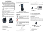
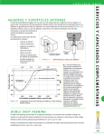
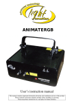
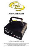
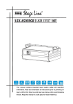
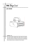
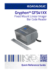
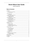
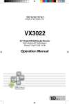
Viper-NET™ Cradle
www.mobile.datalogic.com
World wide Sales Network
available from: www.mobile.datalogic.com/contacts
Datalogic Mobile S.r.l.
Via S. Vitalino, 13
40012 Lippo di Calderara di Reno
Bologna - Italy
Telephone: (+39) 051-3147011
Fax: (+39) 051-3147561
User’s Manual
©2003-2007 Datalogic Mobile S.r.l.
822000351 (Rev. D)
06/07
Datalogic Mobile S.r.l.
Via S. Vitalino 13
40012 - Lippo di Calderara di Reno
Bologna - Italy
Viper-NET™ Cradle
Ed.:06/2007
ALL RIGHTS RESERVED
Datalogic reserves the right to make modifications and improvements without prior notification.
Datalogic shall not be liable for technical or editorial errors or omissions contained herein, nor for incidental or
consequential damages resulting from the use of this material.
Product names mentioned herein are for identification purposes only and may be trademarks and or
registered trademarks of their respective companies.
© - Datalogic S.p.A. 2003 - 2007
CONTENTS
Compliance................................................................................................. iv
WEEE Compliance .......................................................................................iv
1
1.1
GENERAL INFORMATION .......................................................................... 1
Viper-NET™ Cradle ...................................................................................... 1
2
2.1
2.1.1
2.1.2
2.2
2.2.1
2.2.2
INSTALLATION............................................................................................ 3
Mounting the Cradle...................................................................................... 3
Portable Desktop Use ................................................................................... 3
Fixed Desktop Use........................................................................................ 4
Installing Device Drivers on PC..................................................................... 5
RS232 Device Driver Installation .................................................................. 5
USB Device Driver Installation ...................................................................... 8
3
3.1
3.2
CONNECTIONS ........................................................................................... 9
RS232 Connection........................................................................................ 9
USB Connection ......................................................................................... 11
4
TECHNICAL FEATURES ........................................................................... 12
iii
COMPLIANCE
WEEE COMPLIANCE
Informazione degli utenti ai sensi della Direttiva Europea 2002/96/EC
L’apparecchiatura che riporta il simbolo del bidone barrato deve essere smaltita, alla fine della
sua vita utile, separatamente dai rifiuti urbani.
Smaltire l’apparecchiatura in conformità alla presente Direttiva consente di:
evitare possibili conseguenze negative per l’ambiente e per la salute umana che
potrebbero invece essere causati dall’errato smaltimento dello stesso;
recuperare materiali di cui è composto al fine di ottenere un importante risparmio di
energia e di risorse.
Per maggiori dettagli sulle modalità di smaltimento, contattare il Fornitore dal quale è stata
acquistata
l’apparecchiatura
o
consultare
la
sezione
dedicata
sul
sito
www.mobile.datalogic.com.
Information for the user in accordance with the European Commission Directive
2002/96/EC
At the end of its useful life, the product marked with the crossed out wheeled wastebin must be
disposed of separately from urban waste.
Disposing of the product according to this Directive:
avoids potentially negative consequences to the environment and human health
which otherwise could be caused by incorrect disposal
enables the recovery of materials to obtain a significant savings of energy and
resources.
For more detailed information about disposal, contact the supplier that provided you with the
product in question or consult the dedicated section at the website www.mobile.datalogic.com.
iv
Information aux utilisateurs concernant la Directive Européenne 2002/96/EC
Au terme de sa vie utile, le produit qui porte le symbole d'un caisson à ordures barré ne doit pas
être éliminé avec les déchets urbains.
Éliminer ce produit selon cette Directive permet de:
éviter les retombées négatives pour l'environnement et la santé dérivant d'une
élimination incorrecte
récupérer les matériaux dans le but d'une économie importante en termes d'énergie
et de ressources
Pour obtenir des informations complémentaires concernant l'élimination, veuillez contacter le
fournisseur auprès duquel vous avez acheté le produit ou consulter la section consacrée au site
Web www.mobile.datalogic.com.
Información para el usuario de accuerdo con la Directiva Europea 2002/96/CE
Al final de su vida útil, el producto marcado con un simbolo de contenedor de bassura móvil
tachado no debe eliminarse junto a los desechos urbanos.
Eliminar este producto de accuerdo con la Directiva permite de:
evitar posibles consecuencias negativas para el medio ambiente y la salud derivadas
de una eliminación inadecuada
recuperar los materiales obteniendo así un ahorro importante de energía y recursos
Para obtener una información más detallada sobre la eliminación, por favor, póngase en
contacto con el proveedor donde lo compró o consultar la sección dedicada en el Web site
www.mobile.datalogic.com.
Benutzerinformation bezüglich Richtlinie 2002/96/EC der europäischen Kommission
Am Ende des Gerätelebenszyklus darf das Produkt nicht über den städtischen Hausmüll
entsorgt werden. Eine entsprechende Mülltrennung ist erforderlich.
Beseitigung des Produkts entsprechend der Richtlinie:
verhindert negative Auswirkungen für die Umwelt und die Gesundheit der Menschen
ermöglicht die Wiederverwendung der Materialien und spart somit Energie und
Resourcen
Weitere Informationen zu dieser Richtlinie erhalten sie von ihrem Lieferanten über den sie das
Produkt
erworben
haben,
oder
besuchen
sie
unsere
Hompage
unter
www.mobile.datalogic.com.
v
vi
GENERAL INFORMATION
1
1 GENERAL INFORMATION
1.1
VIPER-NET™ CRADLE
The Viper-NET™ cradle paired with one Viper-NET™ terminal builds a Reading
System for the collection, decoding and transmission of barcoded data.
The communication between terminal and host PC through the Viper-NET™ cradle
may occur also by using the standard ActiveSync connection.
D
A
E
B
G
F
C
Figure 1 – Viper-NET™ Cradle General View
Key:
A) LEDs and discharge button
B) IrDA optical interface
C) Terminal contacts
D) Battery slot
E) USB type B connector
F) RS232 connector
G) Power jack
1
Viper-NET™ Cradle
1
The Viper-NET™ cradle is a serial communication adapter between the host
computer and the IrDA optical interface on the Viper-NET™. It also functions as a
battery charger.
By inserting the Viper-NET™ terminal into the cradle data can be transmitted to the
host and its battery begins charging. In addition, an extra battery can be charged by
inserting it into the top of the Viper-NET™ cradle as shown in the following figure.
Data transmission
Extra battery
charge
Figure 2 – Viper-NET™ Cradle Complete Functioning
The LEDs positioned on the front part of the Viper-NET™ cradle (see figure below)
indicate the cradle status:
Figure 3 - LED Indicators
LED
Charger
Green pulse:
IrDA
Power
Green blinking:
Red constant:
Green constant:
Red/Green:
Orange blinking:
Red blinking:
Green:
2
STATUS
it is on for a few seconds when the external
supply or the battery supply has been
recognized.
slow charge.
charging.
charge completed.
they turn on alternatively while discharging.
error.
transmitting data.
it is constant when the cradle is on.
INSTALLATION
2
2 INSTALLATION
2.1
MOUNTING THE CRADLE
The Viper-NET™ cradle consists of a cradle and a base and can be mounted for
portable or fixed desktop usage.
The Viper-NET™ cradle package contains the following:
Viper-NET™ Cradle
This User's Manual
CD-ROM
2.1.1
4 rubber feet
2 screws
1 CAB-417 RS232 cable
Portable Desktop Use
Rubber foot seat (4)
Figure 4 - Rubber Foot Placement
For desktop use, proceed as follows:
1.
2.
3.
Referring to Figure 4, carefully clean the rubber feet seat of the base to remove
any impurities that could reduce adhesion.
Remove the protective plastic from the rubber feet and stick them onto the
bottom surface of the base.
Insert the cradle into the base.
3
Viper-NET™ Cradle
2
2.1.2
Fixed Desktop Use
Fixing screw (2)
Figure 5 - Fixing Screw Placement
Before performing the following operation it is necessary to detach the cradle from its
base by holding the base and pushing the cradle upwards.
For fixed desktop installation proceed as follows:
1.
Position the base on the desired surface;
2.
Fix it on the surface by means of the two screws shown in the figure above.
3.
Insert the cradle into the base.
4
INSTALLATION
2.2
2
INSTALLING DEVICE DRIVERS ON PC
To guarantee a correct RS232 or USB connection between the host and the ViperNET™ terminal through the Viper-NET™ cradle, the related drivers have to be
installed.
In order to install the RS232 driver, it is necessary to have at least the following:
PC with a Pentium processor;
One of the following operating systems:
Windows 2000
Windows XP
For the USB driver installation, it is necessary to have at least the following:
PC with a Pentium processor;
One of the following operating systems:
Windows 98
Windows ME
Windows 2000
Windows XP
NOTE
2.2.1
Once the RS232/USB driver has been installed, the communication
between PC and cradle will be performed through a virtual Infrared
port.
RS232 Device Driver Installation
The following procedure allows installing the RS232 driver on the PC. In particular,
the PC is configured to handle the cradle as an infrared port.
Before performing the installation, ensure that the Viper-NET™ cradle has already
been connected to the PC serial port.
1.
Start the “Add/Remove Hardware Wizard” in the PC Control Panel:
5
2
Viper-NET™ Cradle
2.
Select “Yes, I have already connected the hardware”:
3.
Select the “Add a new hardware device” option from the list below to add the
new driver:
4.
Choose the option allowing to manually select the hardware to be installed:
6
INSTALLATION
5.
Select “Infrared device” as hardware type:
6.
Select “Vishay Telefunken” as Infrared device to be installed:
2
Then, a further window will appear to confirm the selection of the infrared device.
7.
Select the COM port to which you are installing the selected infrared device:
7
Viper-NET™ Cradle
2
8.
Click on the “Finish” button to complete the procedure:
NOTE
2.2.2
Only one infrared device at a time must be active. To disable other
infrared devices, use the Device Manager available in the Control
Panel\System\Hardware folder.
USB Device Driver Installation
For installing the USB driver on the PC, proceed as follows:
1.
Select the “Viper-NET™ Cradle USB-IrDA Adapter” installation from the ViperNET™ CD-ROM and launch it;
2.
An installation wizard starts and guides the user to complete the driver
installation (only the driver installation path is user-definable);
NOTE
If installing the driver in Windows XP operating system, a warning
message about software testing problems appears before completing
the installation. Ignore this message by pressing the “Continue”
button and complete the installation.
Once the driver has been installed on the PC, connect the Viper-NET™ cradle to the
PC by means of the USB cable (see par. 3.2 for USB connection details). The PC
Windows Operating System will detect the new peripheral and the driver installation
process is automatically started by means of a Wizard program. After the driver
installation, Windows finds the appropriate driver to load the USB peripheral.
Now, the Viper-NET™ cradle can communicate with the PC via USB interface.
8
CONNECTIONS
3
3 CONNECTIONS
Connections should always be made with power OFF!
CAUTION
The Viper-NET™ cradle can be connected to a host by means of an RS232
interface, or an USB interface.
Each connection requires a power supply to be connected to the cradle. We
recommend DL FPS18 power supply.
VEXT
GND
Figure 6 - Power Supply Polarity
3.1
RS232 CONNECTION
A single Viper-NET™ cradle can be connected to the host by means of a CAB-417
cable. The RJ45 connector must be connected to the RS232 port of the cradle.
Then, it is necessary to insert the power supply plug into the jack on the cradle and
attach the power supply to a power outlet.
Once the host has been turned on, ensure that the Vishay Telefunken driver has
been activated by checking the IrDA port available in \Control
Panel\System\Hardware\Device Manager folder. Finally, insert the Viper-NET™
terminal into the cradle.
9
Viper-NET™ Cradle
3
A
C
B
D
Figure 7 - RS232 Connection
The cable (provided in the package) and the power supply with its order number are
listed below:
A) Host computer
B) CAB-417 RS232 cable
C) Viper-NET™ cradle
D) 94ACC4595 FPS18 power supply without cord
94ACC1150 Power cord EU 3-pin
Pinout
The CAB-417 allowing the RS232 connection has the following pinout:
Cradle side
RJ45
1
TX
Host/PC side
9-pin D-sub
(female)
RTS
2
3
4
5
6
7
8
8
GND
CTS
RX
DSR
DTR
CD
Figure 8 - CAB-417 Pinout
10
2
5
7
3
4
6
1
CONNECTIONS
3.2
3
USB CONNECTION
Viper-NET™ cradle can be connected to the host by means of a CAB-381 cable (see
par. 2.2.2 for details about the USB driver installation).
Then, it is necessary to insert the power supply plug into the jack on the cradle and
attach the power supply to a power outlet.
Once the host has been turned on, insert the Viper-NET™ terminal into the cradle.
A
B
C
D
Figure 9 - USB Connection
The following cable and power supply are listed with their order number:
A) Host computer
B) 94A051550 CAB-381 USB Type A-B straight cable
C) Viper-NET™ cradle
D) 94ACC4595 FPS18 power supply without cord
94ACC1150 Power cord EU 3-pin
11
Viper-NET™ Cradle
4
4 TECHNICAL FEATURES
Viper-NET™ Cradle
Electrical Features
Power supply *
Consumption
Indicators
Charge time
Communication Features
Interface
Baud rate
Environmental Features
Working temperature**
Storage temperature
Humidity
Degree of protection
Mechanical Features
Dimensions (with base)
Weight (with base)
14 ± 5% VDC
Max. 2 A
Power on LED (green)
IrDA LED (red)
Multi-function LED (two-colors) see par. 1.1
Li-Ion batteries: max. 5 hours
RS232, USB 1.1 version
RS232 = up to 115200 b/sec; USB = up to 12 Mb/sec
0° to +50 °C / +32° to +140 °F
-20° to +70 °C / -4° to +158 °F
90% non condensing
IP40
15.8 x 16.4 x 18.7 cm / 6.22 x 6.46 x 7.36 in
375 g / 13 oz (cradle) + 1175 g / 41 oz (base)
*
Recommended DL power supply: FPS18.
**
Batteries must be charged at a temperature ranging from 0° to +45 °C (+32° to
+113 °F). If the temperature ranges from 0° to +10 °C (+32° to +50 °F) the
charge occurs slowly.
12
Viper-NET™ Cradle
www.mobile.datalogic.com
World wide Sales Network
available from: www.mobile.datalogic.com/contacts
Datalogic Mobile S.r.l.
Via S. Vitalino, 13
40012 Lippo di Calderara di Reno
Bologna - Italy
Telephone: (+39) 051-3147011
Fax: (+39) 051-3147561
User’s Manual
©2003-2007 Datalogic Mobile S.r.l.
822000351 (Rev. D)
06/07