1
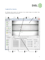
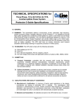
Instrumentation Group
BioSAXS Sample Changer
User Manual
Author: Alexandre Gobbo
Revision: 1.0.0
Date: 22.02.2012
Table of Contents
Functionality ................................................................................................................................................. 3
Introduction .......................................................................................................................................... 3
Plate Loading ......................................................................................................................................... 3
Commands ............................................................................................................................................ 4
Graphical User Interface ............................................................................................................................... 5
Side Bar ................................................................................................................................................. 7
Control Bar ............................................................................................................................................ 8
Status Bar .............................................................................................................................................. 8
Tabs ........................................................................................................................................................... 9
Samples Tab .......................................................................................................................................... 9
Commands Tab ................................................................................................................................... 10
Temperature Tab ................................................................................................................................ 10
Fluid Tanks Tab.................................................................................................................................... 11
Logs Tab .............................................................................................................................................. 11
Alarms Tab .......................................................................................................................................... 12
Advanced Tab...................................................................................................................................... 12
Menus ..................................................................................................................................................... 14
File Menu ............................................................................................................................................ 14
Devices Menu...................................................................................................................................... 15
Help Menu........................................................................................................................................... 16
2
Functionality
Introduction
The BioSAXS Sample Changer is a machine conceived to:
•
Temporally store liquid samples in plates or strips;
•
Transfer the samples to a pod for them to be exposed to X-rays and optionally recuperated;
•
Clean itself – the needle, tubings and capillary - in order to load samples with no contamination;
•
Control the temperature of the samples in the storage plates and also on the exposure pod.
The user can set the sample viscosity (low, medium or high) – used for adjusting the machine
parameters - and type (green, yellow or red). Yellow samples can be used but not recuperated. Red
samples are not acceptable for automatic transfer, they must be handled manually.
All functionality can be remotely accessed by the beamline control but also commanded by the Sample
Changer’s own graphical user interface.
Plate Loading
The first step for the user is to load their sample plates into the Sample Changer by clicking the “Load
Position” button on the application side bar, and opening the cover once the plate table stops.
The plates or stripes should be loaded into the thermal supports. The Sample Changer has three slots for
plate supports:
•
4 x (8+3) PCR strip wells.
•
THERMO-FAST 96 well plate.
•
SBS 96 Deep well plate.
NOTE: Attention to use only standard consumables.
NOTE: The plates should be inserted correctly in their slots. The stripes should be inserted completely. If
they are not then the Sample Changer will refuse the loading when scanning for sample overlap.
After loading the plates the user must close the cover and press “Scan and Park” button.
3
Commands
This is a list of the basic Sample Changer commands:
Fill
Load a given volume of sample from a well. The loading speed is determined based
on the current viscosity. The liquid is detected when reach the pod and the syringe is
stopped when the meniscus is just after the beam mark.
Flow
Samples can be flowed during the data collection time to avid damage. The speed is
calculated in function of the loaded volume. The meniscus at the end of the sample is
detected and, in case it is about to touch the beam mark, the syringe is stopped not
to let air into the beam mark.
Recuperate
A loaded sample can be recuperated to a given well. The speed is determined based
on the current viscosity.
Clean
The sample changer must be cleaned before a new sample is loaded. The Clean
command washes, rinses and dry the needle, tubings and capillary. The timings are
automatically set according to the viscosity.
It is possible to execute this command with modified times; for instance a drying
operation can be performed by setting the wash and rinse times to zero.
Transfer
The sample changer can realize pipetting operations. A given volume of sample can
be transferred from a well to another.
If the destination well contains sample then the depth of liquid is detected inside the
destination well. While releasing the pipetted sample, the needle moves up in order
to push all the transferred volume along the depth of the destination sample. The
purpose is to let the contents reasonably mixed.
Mix
Execute a thorough mixing - typically after a transfer. A given sample volume is
pipetted in and out the well a certain number of cycles.
4
Graphical User Interface
The following picture presents the components of the Sample Changer main window. These
components are detailed in the next sections.
Menu
Title bar
Side bar
Control bar
Status bar
Camera view
Tabs
5
The application interface can be used in the touch screen by the robot or remotely by a KVM or VNC
solution.
The main uses for the touch screen are:
• Assist the user loading plates inside the robot (“Load Position” and “Scan and Park” buttons).
• Display the overall machine state and alarms.
The “Samples” tab displays a representation of the existing sample supports. In order to make it easier
the visualization of a plate, it can be “maximized” by double-clicking its name – see figure below. All
three plates are shown back by double-clicking again the plate name. This is useful for drag-and-drop
operations (see Samples Tab section).
6
Side Bar
This bar presents the main indications of the machine state. Machine errors will be displayed with red
colors.
The only commands in the side bar are the positioning of the table to the plate load position and back to
the parked position: the only operations that should be done inside the experimental hutch.
Overall status of the robot. It is displayed in red if there is an error.
If exposure cell vacuum status not ok displays then red. This is a
beamline signal: it is not ok if the beamline commanded the
vacuum AND the exposure cell vacuum detection is not ok.
The current level of fluid tanks. Display red if empty - in the case
of detergent and water - or full – in the case of waste.
The current storage temperature. Displays yellow if did not reach
the desired setpoint yet.
The current exposure temperature. Displays yellow if did not
reach the desired setpoint yet.
Move the table to the plate load position.
Scan the plates and move the table to parked position (under the cover).
Indicate the table position.
Yellow if the machine cover is open: it must be closed after loading the plates.
Display the sample type: yellow, green or red.
7
Control Bar
Restart button: click to restart the machine control
software.
Abort the ongoing task
(if any), stops all motors
and put the devices back
to a safe state.
NOTE: The confirmation dialog gives the choice to restart
also the hardware. It may be needed following a power
cut. If the hardware is also reinitialized then the sample
in the tubing will be lost.
Move the syringe forward.
Stops it when released
Move the syringe backwards.
Stops it when released
Regulate liquid position. In the case the
liquid won’t stay fixed after loading (due to
thermal effects) press this button to keep it
in position (the meniscus must be visible)
Set the syringe
speed for manual
commands
Status Bar
The machine status: a textual representation of its overall state.
Access level: User or Admin
System time
Activity indicator:
•
Grayed if machine is in error state.
•
Stopped if ready for commands.
•
Moving if currently executing a task.
8
Tabs
Samples Tab
The “Samples Tab” presents simplified access to most common user operations. Each sample well is
drawn as a circle, having indication of row and column. A sample can be selected by clicking over it (or
touching it in the touch panel). A selected sample then can be loaded, recuperated or flown using the
little command box on the right.
Tasks can be triggered by drag-and-drop operations: dragging a sample to the capillary will load it.
Dragging the capillary to a well will recuperated it in the respective well. Dragging a sample to another
will perform a transfer operation.
The sample volume and viscosity considered for these manual commands are those indicated on the
command box on the right.
Color scheme:
• Samples that were not loaded since last plate scan are drawn gray.
• Samples that were already loaded are drawn blue.
• The sample currently loaded is drawn in bright blue.
• The selected sample is highlighted. So it it’s row and column.
9
Commands Tab
This tab presents the commands with a finer control of the parameters. For example one can override
the default setting for viscosity and:
• Clean the tubings choosing different timings for washing, rinsing and drying.
• Fill or recuperate the sample at any speed.
Furthermore this tab contains the mixing command (not present in the “Samples” tab).
Temperature Tab
This tab displays a graph of the storage and exposure temperatures in the past 10 minutes. It has
controls to change temperature setpoints and start/stop the thermostat circulator.
10
Fluid Tanks Tab
This tab presents the level of the fluid tanks during the past 24 hours. It can help to identify anomalies.
Logs Tab
The “Log Tab” displays the application logs – which are also written in daily log files. Each log has a
timestamp, a level (fine, info, warning, severe), an origin (server, interface, controller …) and a
description.
Color scheme:
• Black: normal logs (informational);
• Yellow: warning level.
• Red: severe level.
11
Alarms Tab
This tab shows the application alarms. Alarms are unexpected events with a time span associated. Some
alarms can block the application and make the overall state change to “Alarm” or “Error”.
Color scheme:
• Red: Alarms still active not yet acknowledged by user.
• Magenta: Alarms still active already acknowledged by user.
• Blue: Alarms already inactive but not acknowledged.
• Black: Alarms inactive and acknowledged.
A blinking signal “ALM” on the Status bar is displayed if there is at least one active, not acknowledged,
alarm. Alarms are acknowledged by double-clicking the alarm table.
Advanced Tab
This tab allows the execution of advanced tasks:
12
Panel
Description
Scripts
Execution of scripts (for administrative purposes only).
Control
Start/stop the machine controller (for administrative purposes only).
Syringe
Direct control of the syringe, used for testing purposes.
Calibration Tasks normally done during beamline setup, by the beamline responsible:
Tools
•
Auto-focus.
•
Calibration of light.
•
Needle locating.
•
Full calibration (calibration of focus, light, determination of tubings dead volume
and image scaling).
Scan Supports: should be executed only by the beamline responsible when the type of
sample supports changes.
•
NOTE: IF f the support changes and is not scanned (or properly configured) then
collision may occur.
Scan Plates: repeat the scan for plate barcodes. If this option is selected in “User
Preferences”, plate barcode are always scanned when “Scan and Park” is pressed. This
command can be used if a barcode is hard to read and have not been detected in the first
try.
Light: Allows controlling the light, there are 10 predefined levels but the ideal one is the
middle of the range for which we have more contrast.
•
NOTE: In normal operation should be set to the middle of the range.
Focus: There are three predefined positions: Near, Middle and Far. Middle focus the
middle of the capillary and is ideal for liquid detection. Near and Far focus both capillary
walls, and is useful to check if the walls are dirty.
•
NOTE: In normal operation should be set to Middle.
13
Menus
In normal operation the access to menus is not required. It is important mostly to administrative tasks
and tests.
File Menu
Open a daily log file
Open an alarm history file
Opens a script file (for administrative purposes only)
Opens an image file
Saves a snapshot of the image
Saves a video animation
Selection of access level: User or Administrator (requires password)
Changes the user preferences
Changes the software configuration (for administrative purposes only)
Quit the application
The “User Preferences” dialog allows users to:
• Change parameters typically set by the beamline such as the sample type and viscosity level.
These parameters are considered for remote commands.
• Enable plate barcode scanning: the checkbox should be set if the plates have barcode that
should be read when plate table goes to park position.
• Enable sample detection volume in wells: always checked unless the liquid detection sensor
shows a problem.
• Enable spectrometer read during sample load: if the information is not needed it should remain
unchecked because it slows down the sample loading.
• Disable the alarm monitoring: The “Allow Critical Alarms” checkbox should always be
unchecked. In situations such as when there is a sensor problem and the software is blocked in
“Alarm” status then the user can check “Allow Critical Alarms” to unblock the machine.
Attention in this case because no other relevant alarm will be monitored.
• Disable interlocks. The “Enable Interlocks” checkbox should be always kept checked. If the
software displays “Interlocked” status and cannot move, disabling the interlock may be a
temporary workaround to unblock the machine.
14
Devices Menu
The Devices menu presents forms for
tuning and configuring each
individual device of the system.
This menu is for administrative
purposes and should not be used by
normal users.
15
Help Menu
Open the user documentation.
An application debugger (for administrative purposes only)
Software information and version
16