1
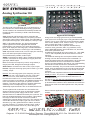
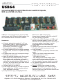
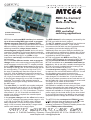
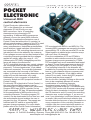
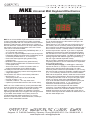
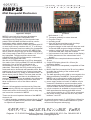
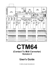
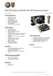
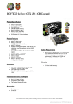
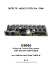
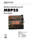
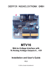
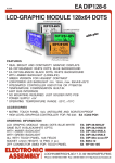
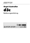
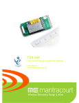
DOEPFER
OEM PRODUCTS 2015-01
This catalogue shows all our OEM products that are
available at present. OEM is the abbreviaton of
original equipment manufacturer. An OEM product is
not a ready-made device but a DIY (do it yourself) kit
that has to be completed by the customer to obtain a
working unit. An OEM product cannot be used
independently but has to be combined with additional
electrical or electronical equipment to become a
working device (e.g. rotary or fader potentiometers,
rotary encoders, buttons, LEDs, keyboard, pitch bend
or modulation wheel, power supply, case/housing and
so on).
Electronic basic knowledge is required to operate
and install an OEM product. For example several
controlling elements - like potentiometers,
buttons, LEDs and similar - have to be added by
the customer and the complete construction has
to be assembled into a suitable case. For OEM
products that have to be connected to mains
voltage (e.g. the MTC power board) installation
and wiring has to be carried out by qualified
personnel only because of electrical safety
(dangerous mains voltage 115V / 230V). Not
qualified personell is not allowed to install and run
such devices! DANGER TO LIFE ! In any case the
user has to read the installation manual carefully
and follow all instructions in the manual
meticulously !
When you are not sure if your knowledge is sufficient
please refrain from ordering and operating an OEM
product. You may consult an expert in your circle of
friends who can help you. We cannot take back
modules that have become defective because of
wrong installation or wrong connection of the
keyboards or controlling elements. We also cannot
take back modules or cables which have been
soldered by the user.
The manufacturer of an OEM product does not know
the final assembly of the complete device in which the
OEM product is used as a part of the complete device.
The final responsibility with regard to electrical safety
and electromagnetic compatibility is up to the user
who is assembling the complete device. On all our
OEM products preventing measures against
electromagnetic radiation are met (e.g. RF filters at
the power supply input and the MIDI lines). But it is
impossible to estimate to what extend the
components added by the user affect the EMC
properties of the complete assembly. Therefore the
complete device has to be shielded against
electromagnetic radiation (incoming and outgoing).
These demands are normally met by a closed metal
case that covers the complete assembly. The metal
case should be connected to GND of the device in
question.
Our OEM/DIY products can be used to built your own
unique midi controller (keyboard 2/3/4/5 octaves +
rotary potentiometers + faders + switches + rotary
encoders) or midi controlled switches (lamps, relays,
magnets, motors, LEDs ....).
www.doepfer.com
DOEPFER
DIY SYNTHESIZER
OEM PRODUCTS
PRODUCTS
OEM
Analog Synthesizer Kit
pc board
The DIY synth is the beginning of a a new product line: a
low cost DIY kit to build a full-fledged analog synthesizer.
The kit is made of an assembled and tested pc board that
includes all that is necessary to build a standard analog
synthesizer:
VCO: Sawtooth and Rectangle output, rectangle with
variable pulse width, four frequency CV inputs (1V/octave
with tempco option) plus summing input, two PW/PWM CV
inputs plus summing input, linear FM input, hard sync input
VCF: 12 dB multimode filter, low, high and bandpass
outputs (optional low-notch-highpass with external
potentiometer), two frequency CV inputs plus summing
input, audio input plus summing input, overdrive/distortion
possible, manual resonance control (up to self oscillation)
VCA: exponential control scale, one CV input plus summing
input, two audio inputs plus summing input,
overdrive/distortion possible, audio output
ADSR: connections for attack, decay, sustain and release
controls, connection for range switch (3 ranges) and LED,
gate input, ADSR output
LFO: connections for frequency control, range switch (3
ranges) and LED, triangle and rectangle outputs
Slew Limiter: connection for slew control, input, output
Inverter: input plus summing input (can be used e.g. to built
a mixer), output
Remark: The summing inputs (VCO frequency CV sum,
VCO PW CV sum, VCF frequency CV sum, VCF audio
sum, VCA CV sum, VCA audio sum) can be used to
increase the number of CV or audio inputs if the available
number of inputs is not sufficient. The additional inputs have
to be connected to the sum input in question via serial
resistors. The value of the resistor in question defines the
sensitivity of the corresponding CV or audio input.
Additionally required resistors are not included with the kit !
The kit is planned for customers who are familiar with
electronic basics as the kit does not include the controls,
switches, sockets, power supply and the case. These
elements have to be added and wired by the customer. The
board is equipped with dual row pin headers. This enables
the usage of dual row female connectors instead of
soldering the controls directly to the pins. The customer can
choose the desired size, shape, type and color of these
elements (e.g. rotary potentiometers or faders, small 3.5
mm jack sockets or ¼" sockets or banana type, small or
large knobs and switches and so on). Even the type of
Application Example
wiring is free: the range goes from a pre-wired standard
synth (VCO-VCF-VCA type) up to a fully patchable modular
system. Two or more of the kits can be combined to obtain
more VCOs, ADSRs, LFOs, VCAs or VCFs, e.g. to built a
more complex pre-wired or modular synth.
We also think about a DIY expansion board that may
contain a noise generator, S&H, ring modulator, mixer,
maybe Midi/USB interface and multi-effect unit, and other
often used synthesizer units.
A stabilized symmetrical 12V power supply (i.e. -12V, GND,
+12V, A-100 compatible) with at least 150 mA current is
required.
The additional working time and required skills to build a
working unit from the kit should not be underrated ! To
obtain all features about 25 potentiometers, 20 sockets and
several switches have to be mounted into a suitable
housing and wired faultless. We ask for your understanding
that we cannot offer the service to troubleshoot a
customer’s assembly. The pc boards comes assembled and
tested. Only the adjustment of the 1V/octave scale and the
frequency offset of the VCO have to be carried out by the
customer.
We do not offer complete units but only the assembled and
tested pc board ! The pictures show application examples
for the DIY synth board. Assemblies like these are not
available from us !
We also do not offer kits with unassembled pc boards (i.e.
kits that include the electronic parts and the unassembled
pc board and the customer has to assemble and solder the
parts) as we made some bad experiences in the past with
such kits.
Some customer application examples are available on our
website:
DOEPFER MUSIKELEKTRONIK GMBH
Geigerstr. 13 D-82166 Graefelfing / Germany Phone 089-89 80 95 10 Fax 089-89 80 95 11
www.doepfer.com [email protected]
DOEPFER
USB64
OEM PRODUCTS
PRODUCTS
OEM
Universal MIDI Control Electronics with 64 inputs,
Midi and USB interface
USB64 is a universal electronics for DIY of Midi
control boxes with USB and/or Midi interface. Up
to 64 elements can be connected to USB64.
q
Headwords:
q 64 inputs, alternatively analog (0...+5V, e.g.
generated by rotary or fader potentiometers,
same as Pocket Electronic) or digital (e.g.
generated by momentary or toggle
switches/buttons, same as CTM64)
q in analog mode Midi control change messages
are generated, resolution 7 bit (Midi data range
0-127)
q in digital mode note on/off or program change
messages are generated
q inputs via eight pin headers with 10 pins each
(same pinout as Pocket Electronic), 10 pin
ribbon cables with suitable female connectors
are plugged to the pin headers, the ribbon
cables are included with the USB64 (about 30
cm each), the other side of each cable is open
to connect the desired controls
q USB and Midi Out (no Midi In)
q power supply alternatively via USB or external
power supply (e.g. for Midi operation without
USB), selectable via jumper
q basic parameters (e.g. analog/digital mode,
q
q
q
q
q
Midi channel, Midi note/program
change/control change range 0-63 or 64-127
etc.) are selected via jumpers
update of the USB64 firmware via USB (e.g. in
case of a firmware update, for this a PC with
Windows XP and USB interface is required), as
soon as an update is available it can be
downloaded from our download page
control LED
measures of the pc board: about 160 length x
55 width x 25 height (measures in mm)
scope of supply:
* USB64 pc board (completely assembled and
testet)
* eight 10 pin ribbon cables with female
headers (about 30 cm each)
* USB cable (A-B type),
* only within Europe: power supply (230V
version with European mains connector
if you order from outside Europe please ask
your local dealer if a power supply is included
For detailed information the user's manual is
available as pdf file.
Remark: USB64 is not suitable for rotary
encoders (sometimes even called endless
potentiometers). For this appliction the Dial
Electronic has to be used as these controls are
no real potentiometers.
DOEPFER MUSIKELEKTRONIK GMBH
Geigerstr. 13 D-82166 Graefelfing / Germany Phone 089-89 80 95 10 Fax 089-89 80 95 11
www.doepfer.com [email protected]
DOEPFER
OEM PRODUCTS
PRODUCTS
OEM
CTM64
Contact-To-MIDI
Universal
MIDI Out Kit
pc board dimensions:
90 x 105 mm
CTM64 is an universal MIDI Out kit. Up to 64 free
contacts can be connected to generate MIDI note on/off or
program change messages. CTM is suitable to retrofit
keyboards, switch panels, button arrangements or any
other contacts so that they are able to transmit MIDI data.
Up to 4 potentiometers can be connected to generate
common MIDI controllers and pitch bend. Additionally a
1/4 jack socket is available for connecting a sustain pedal.
Two different modes are selected with the first of 8
jumpers: note on/off or program change. In the note mode
closing of a contact generates the corresponding MIDI note
on message, opening generates note off - both without
velocity (velocity is fixed to 100). In the program change
mode closing of a contact leads to the corresponding MIDI
program change message.
The note offset (i.e. the MIDI note number assigned to the
first contact) can be set to 0 or 36 with the second jumper.
With two more jumpers one can transpose up/down one
octave, i.e. +12/-12 semitones. Instead of these jumpers a
3-position switch (1-0-1) working as an octave switch can
be soldered to the corresponding pins of the jumper pin
header. In this way the note offsets 0, 12, 24, 36 and 48 are
available. If another note offset (e.g. 41) is required the
contacts are displaced correspondingly and the unused
contact terminals are left free.
In the program change mode the offset can be set to 1 or
64, i.e. setting the program number range to 1-64 or 65-128
(0-63 or 64-127 in MIDI code). With two daisy-chained
CTM64 the whole range 1...128 is covered.
The 4 potentiometer plugs are used to connect up to 4
potentiometers (e.g. rotary, slider, wheels) generating the
MIDI messages pitch-bend, modulation (controller #1),
volume (controller #7) and monophonic after touch.
The 1/4“ jack socket can be used to insert a sustain pedal
(contact type ”closed at rest” is required) generating the
MIDI sustain message (controller #64).
The MIDI channel for all messages transmitted by the
CTM64 is set with the last 4 jumpers.
The 64 contacts are connected to four double row pin
headers with 16 pins each. 16 pin socket-connectors with
flat cable can be connected to these pin headers (not
included with the CTM64). Additionally there is one
common pin for all contacts. Pay attention that only free
contacts can be used. This means that the contacts are not
allowed to be connected with another electronics or
connected with a fixed voltage (e.g. GND).
For the potentiometer four male pcb connectors with 3 pins
(GND, slider, +5V) are available. Suitable female
connectors with assembled cables can be connected to
these pin headers (not included with the CTM64).
CTM64 is equipped with MIDI In and MIDI Out. The
incoming MIDI messages are merged to the data
generated by the CTM64. In this way several CTM64 can
be linked together (e.g. 3 CTM64 required for 2 keyboards
with 61 keys and one basepedal with 32 keys, or switch
boards with more than 64 switches).
CTM64 is available only as an assembled and tested pc
board. The pc board measures are about 90 x 105 mm.
Four mounting holes with 3 mm diameter are available for
mounting the pc board to a suitable base e.g. with distance
sleeves or spacers and screws (black dots in the above
picture). The configuration of CTM64 (i.e. MIDI channel,
mode, note offset and so on) is made by the customer with
8 jumpers - as described above.
We do not offer a suitable housing as the CTM64 is
normally installed into the housing of the keyboard or
switch board.
An external power supply (7-12VDC@min. 250mA) is
required. It is not included with the CTM64. You will find a
suitable power supply in our price list. A connector set
suitable for CTM64 is available at extra charges. This set
includes four 16 pin flat cables with 16 pin socket
connectors pressed to the cables at one end (length about
50cm) and four 3 pin female connectors with assembled
cables for the potentiometers (length about 30cm,
potentiometers are not included).
The counterpart to CTM64 is the MTC64 (= MIDI to
Contact) that converts 64 succeeding note or program
change messages into 64 0/+5V TTL signals. With suitable
drivers relays, lamps or electromagnetic valves can be
controlled via MIDI.
DOEPFER MUSIKELEKTRONIK GMBH
Geigerstr. 13 D-82166 Graefelfing / Germany Phone 089-89 80 95 10 Fax 089-89 80 95 11
www.doepfer.com [email protected]
DOEPFER
OEM PRODUCTS
PRODUCTS
OEM
CTM RELAY BOARD
power supply
output (to other
relay boards)
connectors to CTM64 main board
(common line)
power supply
input
LED controls
relays
relay control inputs (connected to simple on/off contacts)
The CTM Relay Board is an expansion board for the
universal MIDI control electronics CTMC64. The reason
for this this additional board is the limited cable length
between CTM64 main board and the contacts (max.
about 50 cm / 2 ft). By means of the relay board the cable
length can be extended to 100 m (~ 300 ft) and even
more. The working principle is very simple: The relay
board is equipped with 16 reed relays that can be
switched via very long cables. The relay board is placed
near the CTM64 main board and the contacts inside the
relays are the new contacts for the CTM64 main board.
Thus the cable length between the contacts and the
CTM64 main board is less than 50cm but the cables
used to switch the relay can be very much longer. For
each relay a screw terminal is available to connect a
simple 2 pin cable with the controlling contact on the
other side (e.g. a momentary or toggle switch). The relay
board is operated with a separate power supply to obtain
a complete galvanic separation between the relays and
the CTM64 main board.
These are the most important features:
l
16 Reed relays, the contacts of the relays are used as
the contacts for the CTM64 main board
l
l
l
l
l
l
l
l
relay connections via 2 pin screw terminals
up to four CTM relay boards can be connected to one
CTM64 main board
separate power supply for the relay board(s),
independent from the power supply of the CTM64
main board. An external power supply with 7-12V DC
output is required. The required current depends upon
the number of relays that have to be switched actually.
Each relay consumes about 10mA. The full installation
(i.e. 4 relay boards, all relays in operation) requires a
power supply with about 640 mA
additional screw terminal to operate several relay
boards with one power supply only
connection between each CTM relay board and the
CTM64 main board via 16 pin ribbon cable, and one
single cable (common line) that leads from the CTM64
main board to all relay boards
the 16 pin ribbon cable is included with the relay
board
the power supply has to be ordered in addition (only
one required, even if more than one relay board is
used), see accessories and price list
dimensions: 164 x 42 x 18 mm
DOEPFER MUSIKELEKTRONIK GMBH
Geigerstr. 13 D-82166 Graefelfing / Germany Phone 089-89 80 95 10 Fax 089-89 80 95 11
www.doepfer.com [email protected]
DOEPFER
OEM PRODUCTS
PRODUCTS
OEM
MTC64
MIDI-To-Contact/
Gate-Interface
pc board dimensions:
70 x 102 mm
MTC64 is an universal MIDI interface that converts
up to 64 succeeding MIDI note on/off or program
change messages into 64 TTL voltages (0/+5V).
The TTL outputs of the MTC64 can be used to control
different switching functions. With suitable drivers (e.g.
switching transistors) relays, lamps, motors,
electromagnets, magnetic valves and so on can be
controlled. A suitable 16-fold output driver board with
max. 40V/500mA is available for the MTC64. For small
loads (less than 5mA @ 5V, e.g.LEDs or highimpedance reed relays) the additional drivers may not
be necessary.
MTC64 has two different modes: note or program
change mode. In the note mode incoming MIDI note
on/off messages control the 64 TTL outputs provided
that the MIDI channel and note range correspond to
the settings of the MTC64. A note on message will set
the corresponding TTL output to a high level (+5V),
the note off message will reset the output to a low
level (0V). With an additional jumper this bevaviour
can be set to the other way round (note on = low, note
off = high) if reversed outputs are required.
In the program change only one of the 64 outputs is
activated. The number of the activated output is
identical to the program change number received at
the MIDI input.
The note offset (i.e. the MIDI note number assigned
to the first output) can be set to 0 or 36 with another
jumper. With two more jumpers one can transpose
up/down one octave, i.e. +12/-12 semitones. Thus the
note offsets 0, 12, 24, 36 and 48 are obtainable. If
another note offset is required the unused outputs
remain unconnected.
In the program change mode the offset can be set to
1 or 64, i.e. setting the program number range to 1-64
or 65-128 (0-63 or 64-127 in MIDI code). With two
daisy-chained MTC64 the whole program number
range 1-128 is covered. Alternatively a range switch
can be used instead of the range jumper.
Universal kit for
MIDI controlled
switching applications
The MIDI channel for all messages processed by the
MTC64 is set with the last 4 jumpers.
The 64 TTL outputs are available as four double row
pin headers with 16 pins each. 16 pin socketconnectors with flat cable can be connected to these
pin headers (not included with the MTC64).
Additionally there are some GND pins available (as
solder pins and as additional pin header with 10 pins)
as a GND reference level is required for the devices
controlled by the MTC64 outputs.
MTC64 is equipped with MIDI In and Thru. The
incoming MIDI messages are passed to MIDI Thru. In
this way several MTC64 can be linked together.
MTC64 is available as an assembled and tested pc
board only. We do not offer a suitable housing as the
MTC64 is normally installed into the housing of the
device to be controlled by MTC64.
An external power supply (7-12VDC@min. 250mA)
is required. It is not included with the MTC64. You will
find a suitable power supply in our price list.
A connector set suitable for MTC64 is available at
extra charges.This includes four 16 pin flat cables
with 16 pin socket connectors at one end and one 10
pin flat cable with 10 pin socket connector at one end.
The length for all cables is about 50cm.
A suitable 16-fold output driver board with max.
40V/500mA is available at extra charges. Each output
board is connected to the main board simply with a
flat cable (included with the driver board). The driver
outputs are available as 16 single pin holders. The
power supply for the loads driven by the driver board
is not included and has to be added by the customer
(depends upon the voltage and current of the loads).
The MTC64 is the counterpart to CTM64 (Contactto-MIDI Interface) that generates up to 64 MIDI note
on/off or program change messages with free
contacts connected to CTM64 (for details please refer
to the CTM64 product information).
DOEPFER MUSIKELEKTRONIK GMBH
Geigerstr. 13 D-82166 Graefelfing / Germany Phone 089-89 80 95 10 Fax 089-89 80 95 11
www.doepfer.com [email protected]
DOEPFER
OEM PRODUCTS
PRODUCTS
OEM
MTC RELAY BOARD
connectors to
MTC64 main board
relays
LED controls
relay outputs
The MTC Relay Board is an expansion board for the
universal MIDI control electronics MTC64. It has 16
relays available that can be used as switches for many
applications (e.g. audio signals, control signals, low
voltage lamps/motors/magnets and many more). Another
application is to connect the relay outputs in parallel to
the key contacts of a synthesizer, organ or any electronic
instrument that cannot be interfaced to Midi with another
method.
These are the most important features:
l
16 potential-free relay contacts (Reed relays)
l
maximum current for each relay contact: 1A
l
maximum voltage for each relay contact: 50V
l
maximum power for each relay contact: 15W (15VA)
(it is not allowed to go beyond any of these values,
e.g. for 1A current the maximum voltage is 15V,
otherwise the maximum power of 15VA would be
exceeded)
l
l
l
l
l
l
l
l
residual resistance of closed contact: 150mOhm
relay connections via screw terminals
LED control for each output
up to four MTC relay boards can be connected to one
MTC64 main board
connection between MTC relay boards and MTC64
main board via one 10 pin ribbon cable leading from
the main board to all relay boards, and a 16 pin
ribbon cable between main board and relay board
(one for each relay board). Please specify how many
relay boards have to be connected to the main board
(because of the lenght and number of female
connectors of the 10 pin ribbon cable)
ribbon cables are included with the relay board,
cables for relay connections are not included
dimensions: 163 x 52 x 18 mm
For more detailed information the user's guide is
available for download on our web site
DOEPFER MUSIKELEKTRONIK GMBH
Geigerstr. 13 D-82166 Graefelfing / Germany Phone 089-89 80 95 10 Fax 089-89 80 95 11
www.doepfer.com [email protected]
DOEPFER
POCKET
ELECTRONIC
OEM PRODUCTS
PRODUCTS
OEM
Universal MIDI
control electronics
Pocket Electronics (abbreviation:
"PE" in the following) is an universal
electronics DIY kit to built your own
MIDI control box. Up to 16 controlling
elements can be connected to PE
transmitting 16 different MIDI messages on
different (or even the same) MIDI channels.
Essentially it contains the electronics core of
Pocket Control but without the 16 controls (i.e.
without potentiometers). Instead of this PE is used
to connect up to 16 controlling elements (e.g.
rotary potentiometers, fader/slider potentiometer,
touch switches, toggle switches, foot switches,
foot controllers). The controlling elements are not
included but have to be added by the customer.
Even voltages sources can be used instead of the
controlling elements provided that the voltages
applied are strictly within the range 0...+5V
(referenced to PE GND)! Voltages beyond this
range will destroy the electronics !
The 16 controlling elements resp. control voltages
are connected to two double row pinheaders (10
pins each). To these headers two 10 pin ribbon
cables are connected. The controlling elements
are connected to the free ends of the ribbon
cables. In this way the controlling elements can be
pulled off from the electronics very easily.
Additionally a 4 pin connector is available to
connect a button and LED (snapshot function of
Pocket Control).
Functionally PE is identical to Pocket Control, i.e.
the most common Midi messages can be
generated (any controller, after touch, pitch bend,
common RPN resp. NRPN controller, but no
SysEx messages). PE has 128 presets available
for the assignement of MIDI events to the 16
controlling elements. The editor program (PC
version) can be downloaded for free from our web
site www.doepfer.de and enables the user to
program his own 128 presets. The presets are
selected with DIP switch or incoming MIDI
program change messages. For more details
please refer to the Pocket Control information ).
PE is equipped with MIDI In and MIDI Out. The
incoming MIDI messages are merged to the data
generated by PE. In this way several PE can be
linked together to obtain larger controller arrays
with more than 16 elements.
Even the combination of PE and CTM64 is
possible to add controller events to the note or
program change events generated by CTM64.
PE is available only as an assembled and tested
pc board. The pc board measures are about 80
mm (length) x 56 mm (width) x 25 mm (height).
Five mounting holes with 3 mm diameter are
available for mounting the pc board to a suitable
base e.g. with distance sleeves or spacers and
screws. PE includes two 10 pin ribbon cables
(about 30 cm each), button and LED (snapshot
function) and the power supply.Ê
We do not offer a suitable housing as this would
have to be completely different for various
combinations of controlling elements.
An external power supply (7-12VDC@min.
100mA) is required for the PE. It is included with
the PE (230V version with European mains plug).
Electronic basic knowledge is required to install
the PE electronics and to connect the controlling
elements resp. control voltages. If you are not
sure if your knowledge is sufficient please consult
an expert. We cannot take back modules that
became defective because of wrong installation or
wrong connection of the controlling elements or
voltages. We also cannot take back modules or
cables which have been soldered by the user.
DOEPFER MUSIKELEKTRONIK GMBH
Geigerstr. 13 D-82166 Graefelfing / Germany Phone 089-89 80 95 10 Fax 089-89 80 95 11
www.doepfer.com [email protected]
DOEPFER
WHEEL
ELECTRONIC
OEM PRODUCTS
PRODUCTS
OEM
Universal Midi electronics
for wheels, foot controllers
joy-sticks, breath-controllers
Wheel Electronic (abbreviation: "WE" in the following) is a
universal electronics DIY Midi kit designed to connect
modulation or pitch wheels. But it can be used also for joy
sticks, single or multiple foot controllers (analog or on/off),
breath controllers or even normal potentiometers. In addition
a connector for a sustain foot switch is available. Up to 4
continuously variable "analog" elements and a "digital"
switching element (e.g. a sustain foot switch) can be
connected.
Application examples:
q wheels
q pitch bender
q joy sticks
q breath controllers
q foot controllers (continuos)
q foot switches (on/off), momentary or toggle
q rotary potentiometers
q slider/fader potentiometers
of rotation. Even breath controllers (e.g. Yamaha BC-1/2/3)
output only about +3.5V maximal control voltage.
For each of the four elements a jumper is used to select if
the full voltage range (0...+5V) or the adjustable voltage
range is used for measurement. This is necessary if
different elements are used simultaneously (e.g. modulation
wheel and slider potentiometers).
If an element is assigned to Midi pitch bend a "plateau" is
used in the middle of the voltage/data range (data value
64). This feature is meaningful in combination with springloaded wheels or joy sticks as due to mechanical tolerances
the exact center position is not always reached.
Four jumpers are used to select the Midi channel.
Further four jumpers are used to select up to 16 different
Different elements can be combined simultaneously. Here
combinations of Midi control change numbers, pitch bend or
are some examples:
after touch - the so-called presets. A detailed list of all
q pitch bender, modulation wheel, volume control (rotary or available combinations can be found in the user's manual
slider potentiometer), breath controller and sustain foot
The elements connected to WE (e.g. wheels, joy sticks, foot
switch
controllers, normal potentiometers, foot switch) are not
included but have to be added or purchased in addition by
q pitch bender, three modulation wheels (e.g. modulation,
volume, after touch) and sustain foot switch
the customer. The Midi data range is 0...127 with 7 bit
resolution.
q pitch bender, two modulation wheels (e.g. modulation
and after touch), one rotary or slider potentiometer
The sampling rate is about 50 samples/second.
(volume) and sustain foot switch
WE is equipped with MIDI In and MIDI Out. The incoming
MIDI messages are merged to the data generated by WEq pitch bender, modulation wheel and joy stick
provided that the incoming Midi data range is not too big. In
q two joy sticks
this way several WE can be linked together or combined
q four foot controllers for volume control of four Midi
channels
with other electronics like CTM64, MKE, Pocket Electronic
q dual or tripe foot controller (on/off or analog) and rotary or or Dial Electronic).
slider potentiometer
An LED is used to indicate the Midi activity.
WE is available only as an assembled and tested pc board.
q two modulation wheels or switches to control the rotary
speakers of the organ software B4 (von Native
The pc board measures are about 60 mm (length) x 55 mm
Instruments), two rotary or slider potentiometers for
(width) x 25 mm (height). Several mounting holes with 3 mm
volume and expression
diameter are available for mounting the pc board to a
suitable base e.g. with distance sleeves or spacers and
The four "analog" elements are connected to pinheaders
screws.
with 3 pins. For the "digital" switching element a pinheader
We do not offer a suitable housing as this would have to be
with 2 pins is available. Four 3-pin cable sets and one 2-pin
completely different for various combinations of controlling
cable set about 30cm each with suitable female connectors
elements.
are included.
An external power supply (7-12VDC@min. 100mA) is used.
WE has some special features:
Within Europe the wall outlet power supply adapter for 230V
The upper voltage that is assigned to the Midi data value
mains voltage and European type mains plug is included
127 can be adjusted exactly with a multi-gang trimming
with the WE. In other countries the power supply has to be
potentiometer in the range +3...+5V. This measure is
purchased by the user in his country. If there is a Doepfer
necessary e.g. for modulation or pitch wheels, foot
representative in your country please ask the representative
controllers or joy sticks that do not cover the complete angle if the power supply is included in your country.
DOEPFER MUSIKELEKTRONIK GMBH
Geigerstr. 13 D-82166 Graefelfing / Germany Phone 089-89 80 95 10 Fax 089-89 80 95 11
www.doepfer.com [email protected]
DOEPFER
OEM PRODUCTS
PRODUCTS
OEM
MKE Universal Midi Keyboard Electronics
MKE is an Universal Midi Keyboard Electronics to built
custom-made Midi controllers that include a keyboard.
Combining the MKE with our controller electronics Pocket
Electronic, Dial Electronic, Wheel Electronic, CTM64 or
MTC64 allows the construction of an unique Midi controller
that exactly meets the requirements of the user. These
units can be connected to MKE:
l
Any keyboard manufactured by FATAR/Italy with 2, 3, 4
or 5 octaves (with velocity)
l
By means of a special adapter board even the dynamic
basspedals PD/2A manufactured by FATAR/Italy can be
connected (avialable with 13, 17 or 20 keys)
l
Pitch bend wheel (special spring-loaded rotary
potentiometer)
l
Modulation wheel (special rotary potentiometer)
l
Rotary or fader potentiometer for loudness/volume
control (Midi CC#7)
l
After touch sensor or socket for sustain switch or
another potentiometer for any Midi controller
The MKE pc board has these controls available:
l
6 rectangle momentary buttons with integrated LEDs
l
3-digit LED display
The 6 buttons are used to control these parameters:
l
Midi channel 1...16
l
Transpose (lowest note = 0,12,24,36,48,60)
l
Program change 0...127
l
Controller number 0...127 resp. After touch
l
Up/down (increment/decrement of the current value)
MKE has a non-volatile memory for the parameters Midi
channel, transpose, program and controller number. After
the next power on the previous values are called up.
MKE is equipped with Midi In and Midi Out. The data
appearing at the Midi in are merged to the data generated
by the MKE. Several MKE can be daisy-chained or
combined with other OEM controllers (e.g. Pocket
Electronic, Dial Electronic, Wheel Electronic, CTM64) to
built a custom-made Midi controller.
MKE is available as an assembled and tested pc board.
The pc board measures are about 68 mm (length) x 85
(width) x 35 mm (height).
Please specify in your order the type of keyboard (2/3 or
4/5 octaves). This is necessary as the keyboards with 2
and 3 octaves have different connectors compared to the 4
and 5 octaves versions. Suitable cables to connect MKE
and the keyboard are required. If you have no keyboard
available we recommend to order the keyboard together
with the MKE as in this case the components are already
connected and tested together. The MKE is available as a
package together with different types of keyboards (e.g.
with the organ waterfall keyboard TP/8O).
We do not offer a suitable housing as this would have to be
completely different for various combinations of keyboards
and controlling elements.
An external power supply (7-12VDC@min. 250mA) is
required for the PE. In Europe it is included with the MKE
(230V version with European mains plug). For other
countries please contact the representative in your country.
We have several accessories available: suitable keyboards
(2, 3, 4 or 5 octaves), cables for the connection between
MKE and the keyboards, wheels, cable sets for the wheels
and the volume potentiometer, wheels and sustain socket.
For details please take a look at our price list (spare parts
section) or ask our sales office ([email protected]).
If you order the MKE without keyboard please specify the
keyboard that will be used (2, 3, 4 or 5 octaves). The
connectors are different for the keyboards and the
electronics has to be equipped with the suitable
connectors. The cables leading to the keyboards are not
included and have to be ordered in addition. For more
detailed information the user's guide and a guide how to
connect other keyboards are available for download on our
web site www.doepfer.com.
DOEPFER MUSIKELEKTRONIK GMBH
Geigerstr. 13 D-82166 Graefelfing / Germany Phone 089-89 80 95 10 Fax 089-89 80 95 11
www.doepfer.com [email protected]
DOEPFER
MBP25
OEM PRODUCTS
PRODUCTS
OEM
Midi Basspedal Electronics
application example
MBP25 is an electronics that was developed to
connect the non-dynamic basspedals PD/3
manufactured by Fatar/Italy (for the dynamic bass
pedals PD/2A the MKE electronics can be used in
combination with a suitable adapter board).
Unfortunately Fatar does not offer bass pedals with 25
or more keys but only versions with 13, 17 or 20 keys.
As many customers have been asking for a basspedal
with 25 keys we decided to develop the MBP25 that
can be used to connect one, two or three basspedals
with 13 keys each (Fatar PD/3) to obtain a 13, 25 or 37
key basspedal. The above picture shows one
possibility how two PD/3 pedals can be combined to
obtain a 25 key pedal with case.
We offer a DIY/OEM package for a 25 key basspedal.
It is made of two 13 keys pedals PD/3 and the MBP25
electronics. One of the two pedals has to be
shortended by one key as one of the "C" keys is
redundant. Fortunately the PD/3 pedals use a plastic
frame and can be shortened with passable effort. Both
pedals have to be mounted on a common base plate
and a suitable case (e.g. made of varnished wood - as
shown above) can be added. The base plate and the
case are not included and have to be added by the
customer. A third pedal can be added in the same way.
For this application a special connection cable with
three connectors on one of the ribbon cables is
required.
Remark: All basspedals manufactured by Fatar that
include velocity (PD/2A) are equipped with solid steel
frames and cannot be shortened in such an easy way
and cannot be connected to MBP25.
pc board
u
u
u
u
u
q
q
q
q
q
q
q
Midi channel 1...16
Transpose probably in octave intervals
Program Change
operating mode:
note: this is the usual play mode, the keys
transmit Midi note on/off message
u program change: in this mode the keys are used
to transmit Midi program change messages
u realtime: in this mode three of the keys are used
to transmit Midi start, stop and continue
u Up (increment of the value shown in the display)
u Down (decrement of the value shown in the
display)
measures of the complete button area about 76 x
22 mm
3-digit LED display (about 19 x 38 mm) for
parameter display
two connectors for basspedals (compatible to Fatar
PD/3)
Midi In, Midi Out (connected via 30 cm long cables
to enable the mounting of the sockets at the
desired position)
The data appearing at the Midi in are merged to the
data generated by the MBP25. Consequently the
MBP25 can be connected to a Midi keyboard to
add the basspedal data to the keyboard data.
power supply socket on board, in addition a 2-pin
connector is available to connect another power
supply socket near the Midi sockets (2-pin cable 30
cm with suitable female connector is included)
a 3-pin connector is available to connect a rotary or
fader potentiometer that transmits Midi volume,
even a foot controller (e.g. FP5) can be connected.
the (fixed) velocity value can be set to any value
between 1 and 127.
q
These are the most important features of the MBP25
electronic kit:
q 6 black rectangle momentary buttons (about 12 x 22 An external power supply (7-12VDC@min. 100mA) is
mm) with integrated LEDs (same as used in MKE)
required for the PE. It is included with the PE (230V
to adjust these parameters
version with European mains plug).
DOEPFER MUSIKELEKTRONIK GMBH
Geigerstr. 13 D-82166 Graefelfing / Germany Phone 089-89 80 95 10 Fax 089-89 80 95 11
www.doepfer.com [email protected]
DOEPFER
!
!
!
!
!
!
!
!
!
!
!
MTV16
OEM PRODUCTS
PRODUCTS
OEM
Midi-to-Voltage Interface with 16
Analog Voltage Outputs
interface to convert midi control changes messages to analog voltages
16 analog voltage outputs 0 ... +5V, max. load ~ 10kOhm
optional amplifier board for 0...+10V available upon request
resolution of the voltages: 128 steps or 7 bit (based on the 7 bit midi data)
the voltages are available as two pin heades with 10 pins each, each pin
header has available 8 voltages and GND on two pins
the voltages are controlled by 16 subsequent midi control changes messages
on the same midi channel
the midi channel is adjusted by means of four jumpers
the control change number of the first output can be set to 0, 16, 32, 48, 64,
80, 96 or 112 by means of three jumpers
connectors for power supply and midi are available as sockets on the pcb
Midi activity LED display
ready built and tested pc board, dimensions: about 78 x 67 x 25 mm
DOEPFER MUSIKELEKTRONIK GMBH
Geigerstr. 13 D-82166 Graefelfing / Germany Phone 089-89 80 95 10 Fax 089-89 80 95 11
www.doepfer.com [email protected]