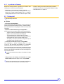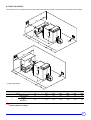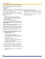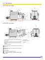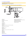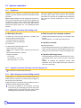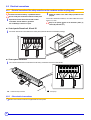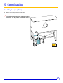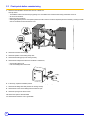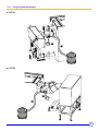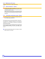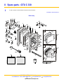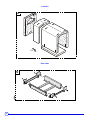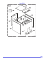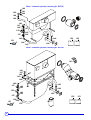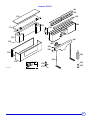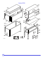
1
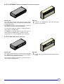
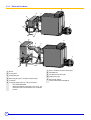
EN Oil-fired condensing boiler GTU C 330 C001933-C Installation and Service Manual 300016152-001-C Declaration of conformity 1 C001950 The appliance complies with the standard model described in declaration of compliance 1. It is manufactured and distributed pursuant to the requirements of European Directives. The original of the declaration of compliance is available from the manufacturer. 2 GTU C 330 07/04/2009 - 300016152-001-C Contents 1 Introduction . . . . . . . . . . . . . . . . . . . . . . . . . . . . . . . . . . . . . . . . . . . . . . . . . . . . . . . . . . . . . . . . . . . . . . . . . . . . .5 1.1 1.2 Symbols and abbreviations . . . . . . . . . . . . . . . . . . . . . . . . . . . . . . . . . . . . . . . . . . . . . . . . . . . . . . . . . . . . . . . . . . . . . . . . . . . . . . . .5 General. . . . . . . . . . . . . . . . . . . . . . . . . . . . . . . . . . . . . . . . . . . . . . . . . . . . . . . . . . . . . . . . . . . . . . . . . . . . . . . . . . . . . . . . . . . . . . . .5 1.2.1 Manufacturer's liability . . . . . . . . . . . . . . . . . . . . . . . . . . . . . . . . . . . . . . . . . . . . . . . . . . . . . . . . . . . . . . . . . . . . . . . . . . . . . .5 1.2.2 Installer's liability . . . . . . . . . . . . . . . . . . . . . . . . . . . . . . . . . . . . . . . . . . . . . . . . . . . . . . . . . . . . . . . . . . . . . . . . . . . . . . . . . .5 1.2.3 User's liability . . . . . . . . . . . . . . . . . . . . . . . . . . . . . . . . . . . . . . . . . . . . . . . . . . . . . . . . . . . . . . . . . . . . . . . . . . . . . . . . . . . . .5 1.3 Homologations . . . . . . . . . . . . . . . . . . . . . . . . . . . . . . . . . . . . . . . . . . . . . . . . . . . . . . . . . . . . . . . . . . . . . . . . . . . . . . . . . . . . . . . . . .6 2 Safety instructions and recommendations. . . . . . . . . . . . . . . . . . . . . . . . . . . . . . . . . . . . . . . . . . . . . . . . . . . .7 2.1 2.2 3 Safety instructions . . . . . . . . . . . . . . . . . . . . . . . . . . . . . . . . . . . . . . . . . . . . . . . . . . . . . . . . . . . . . . . . . . . . . . . . . . . . . . . . . . . . . . .7 Recommendations . . . . . . . . . . . . . . . . . . . . . . . . . . . . . . . . . . . . . . . . . . . . . . . . . . . . . . . . . . . . . . . . . . . . . . . . . . . . . . . . . . . . . . .7 Technical description . . . . . . . . . . . . . . . . . . . . . . . . . . . . . . . . . . . . . . . . . . . . . . . . . . . . . . . . . . . . . . . . . . . . .8 3.1 3.2 3.3 General description . . . . . . . . . . . . . . . . . . . . . . . . . . . . . . . . . . . . . . . . . . . . . . . . . . . . . . . . . . . . . . . . . . . . . . . . . . . . . . . . . . . . . .8 Technical characteristics . . . . . . . . . . . . . . . . . . . . . . . . . . . . . . . . . . . . . . . . . . . . . . . . . . . . . . . . . . . . . . . . . . . . . . . . . . . . . . . . . .9 Main parts. . . . . . . . . . . . . . . . . . . . . . . . . . . . . . . . . . . . . . . . . . . . . . . . . . . . . . . . . . . . . . . . . . . . . . . . . . . . . . . . . . . . . . . . . . . . .10 3.3.1 Control panels . . . . . . . . . . . . . . . . . . . . . . . . . . . . . . . . . . . . . . . . . . . . . . . . . . . . . . . . . . . . . . . . . . . . . . . . . . . . . . . . . . .10 3.3.2 Boiler and Condenser . . . . . . . . . . . . . . . . . . . . . . . . . . . . . . . . . . . . . . . . . . . . . . . . . . . . . . . . . . . . . . . . . . . . . . . . . . . . .12 3.4 Operating principle . . . . . . . . . . . . . . . . . . . . . . . . . . . . . . . . . . . . . . . . . . . . . . . . . . . . . . . . . . . . . . . . . . . . . . . . . . . . . . . . . . . . . .13 4 Installation . . . . . . . . . . . . . . . . . . . . . . . . . . . . . . . . . . . . . . . . . . . . . . . . . . . . . . . . . . . . . . . . . . . . . . . . . . . . .14 4.1 Regulations governing installation . . . . . . . . . . . . . . . . . . . . . . . . . . . . . . . . . . . . . . . . . . . . . . . . . . . . . . . . . . . . . . . . . . . . . . . . . .14 4.1.1 In general . . . . . . . . . . . . . . . . . . . . . . . . . . . . . . . . . . . . . . . . . . . . . . . . . . . . . . . . . . . . . . . . . . . . . . . . . . . . . . . . . . . . . . .14 4.1.2 In particular for France . . . . . . . . . . . . . . . . . . . . . . . . . . . . . . . . . . . . . . . . . . . . . . . . . . . . . . . . . . . . . . . . . . . . . . . . . . . . .14 4.1.3 In particular for Germany . . . . . . . . . . . . . . . . . . . . . . . . . . . . . . . . . . . . . . . . . . . . . . . . . . . . . . . . . . . . . . . . . . . . . . . . . . .15 4.2 Package list . . . . . . . . . . . . . . . . . . . . . . . . . . . . . . . . . . . . . . . . . . . . . . . . . . . . . . . . . . . . . . . . . . . . . . . . . . . . . . . . . . . . . . . . . . .15 4.3 Mounting. . . . . . . . . . . . . . . . . . . . . . . . . . . . . . . . . . . . . . . . . . . . . . . . . . . . . . . . . . . . . . . . . . . . . . . . . . . . . . . . . . . . . . . . . . . . . .16 4.3.1 Position of the boiler. . . . . . . . . . . . . . . . . . . . . . . . . . . . . . . . . . . . . . . . . . . . . . . . . . . . . . . . . . . . . . . . . . . . . . . . . . . . . . .16 4.3.2 Aeration . . . . . . . . . . . . . . . . . . . . . . . . . . . . . . . . . . . . . . . . . . . . . . . . . . . . . . . . . . . . . . . . . . . . . . . . . . . . . . . . . . . . . . . .18 4.3.3 Main dimensions . . . . . . . . . . . . . . . . . . . . . . . . . . . . . . . . . . . . . . . . . . . . . . . . . . . . . . . . . . . . . . . . . . . . . . . . . . . . . . . . .19 4.3.4 Assembling the appliance . . . . . . . . . . . . . . . . . . . . . . . . . . . . . . . . . . . . . . . . . . . . . . . . . . . . . . . . . . . . . . . . . . . . . . . . . .20 4.4 Example of an installation. . . . . . . . . . . . . . . . . . . . . . . . . . . . . . . . . . . . . . . . . . . . . . . . . . . . . . . . . . . . . . . . . . . . . . . . . . . . . . . . .21 4.5 Hydraulic connections . . . . . . . . . . . . . . . . . . . . . . . . . . . . . . . . . . . . . . . . . . . . . . . . . . . . . . . . . . . . . . . . . . . . . . . . . . . . . . . . . . .22 4.5.1 Regulations . . . . . . . . . . . . . . . . . . . . . . . . . . . . . . . . . . . . . . . . . . . . . . . . . . . . . . . . . . . . . . . . . . . . . . . . . . . . . . . . . . . . .22 4.5.2 Hydraulic connection of the heating circuit. . . . . . . . . . . . . . . . . . . . . . . . . . . . . . . . . . . . . . . . . . . . . . . . . . . . . . . . . . . . . .22 4.5.3 Hydraulic connection of the water circuit for domestic use . . . . . . . . . . . . . . . . . . . . . . . . . . . . . . . . . . . . . . . . . . . . . . . . .22 4.5.4 Water discharge connection (Sludge removal) . . . . . . . . . . . . . . . . . . . . . . . . . . . . . . . . . . . . . . . . . . . . . . . . . . . . . . . . . .22 4.5.5 Safety valve . . . . . . . . . . . . . . . . . . . . . . . . . . . . . . . . . . . . . . . . . . . . . . . . . . . . . . . . . . . . . . . . . . . . . . . . . . . . . . . . . . . . .23 4.5.6 Connecting the condensates discharge conduit . . . . . . . . . . . . . . . . . . . . . . . . . . . . . . . . . . . . . . . . . . . . . . . . . . . . . . . . .23 4.5.7 Water treatment . . . . . . . . . . . . . . . . . . . . . . . . . . . . . . . . . . . . . . . . . . . . . . . . . . . . . . . . . . . . . . . . . . . . . . . . . . . . . . . . . .24 4.5.8 Refilling the installation . . . . . . . . . . . . . . . . . . . . . . . . . . . . . . . . . . . . . . . . . . . . . . . . . . . . . . . . . . . . . . . . . . . . . . . . . . . .25 4.6 Connecting the burner . . . . . . . . . . . . . . . . . . . . . . . . . . . . . . . . . . . . . . . . . . . . . . . . . . . . . . . . . . . . . . . . . . . . . . . . . . . . . . . . . . .26 4.7 Flue gas system connections . . . . . . . . . . . . . . . . . . . . . . . . . . . . . . . . . . . . . . . . . . . . . . . . . . . . . . . . . . . . . . . . . . . . . . . . . . . . . .27 4.7.1 Flue size. . . . . . . . . . . . . . . . . . . . . . . . . . . . . . . . . . . . . . . . . . . . . . . . . . . . . . . . . . . . . . . . . . . . . . . . . . . . . . . . . . . . . . . .27 4.7.2 Connection to the flue gas pipe . . . . . . . . . . . . . . . . . . . . . . . . . . . . . . . . . . . . . . . . . . . . . . . . . . . . . . . . . . . . . . . . . . . . . .27 4.8 Electrical connections. . . . . . . . . . . . . . . . . . . . . . . . . . . . . . . . . . . . . . . . . . . . . . . . . . . . . . . . . . . . . . . . . . . . . . . . . . . . . . . . . . . .28 4.8.1 Electrical connection of the safety control box on the condenser and the recycling pump . . . . . . . . . . . . . . . . . . . . . . . . .28 4.8.2 Other electrical connections. . . . . . . . . . . . . . . . . . . . . . . . . . . . . . . . . . . . . . . . . . . . . . . . . . . . . . . . . . . . . . . . . . . . . . . . .28 5 Commissioning . . . . . . . . . . . . . . . . . . . . . . . . . . . . . . . . . . . . . . . . . . . . . . . . . . . . . . . . . . . . . . . . . . . . . . . . .29 5.1 5.2 5.3 6 Filling the siphon (Option). . . . . . . . . . . . . . . . . . . . . . . . . . . . . . . . . . . . . . . . . . . . . . . . . . . . . . . . . . . . . . . . . . . . . . . . . . . . . . . . .29 Check points before commissioning. . . . . . . . . . . . . . . . . . . . . . . . . . . . . . . . . . . . . . . . . . . . . . . . . . . . . . . . . . . . . . . . . . . . . . . . .30 Commissioning . . . . . . . . . . . . . . . . . . . . . . . . . . . . . . . . . . . . . . . . . . . . . . . . . . . . . . . . . . . . . . . . . . . . . . . . . . . . . . . . . . . . . . . . .31 Stopping the boiler . . . . . . . . . . . . . . . . . . . . . . . . . . . . . . . . . . . . . . . . . . . . . . . . . . . . . . . . . . . . . . . . . . . . . .32 07/04/2009 - 300016152-001-C GTU C 330 3 6.1 6.2 7 Checking and maintenance . . . . . . . . . . . . . . . . . . . . . . . . . . . . . . . . . . . . . . . . . . . . . . . . . . . . . . . . . . . . . . .33 7.1 7.2 7.3 7.4 8 4 Placing the plant out of service. . . . . . . . . . . . . . . . . . . . . . . . . . . . . . . . . . . . . . . . . . . . . . . . . . . . . . . . . . . . . . . . . . . . . . . . . . . . .32 Antifreeze protection. . . . . . . . . . . . . . . . . . . . . . . . . . . . . . . . . . . . . . . . . . . . . . . . . . . . . . . . . . . . . . . . . . . . . . . . . . . . . . . . . . . . .32 6.2.1 Precautions required in the case of long boiler stops (one or more years) . . . . . . . . . . . . . . . . . . . . . . . . . . . . . . . . . . . . .32 6.2.2 Precautions required if the heating is stopped when there is a risk of freezing . . . . . . . . . . . . . . . . . . . . . . . . . . . . . . . . . .32 Checks . . . . . . . . . . . . . . . . . . . . . . . . . . . . . . . . . . . . . . . . . . . . . . . . . . . . . . . . . . . . . . . . . . . . . . . . . . . . . . . . . . . . . . . . . . . . . . .33 Hydraulic pressure . . . . . . . . . . . . . . . . . . . . . . . . . . . . . . . . . . . . . . . . . . . . . . . . . . . . . . . . . . . . . . . . . . . . . . . . . . . . . . . . . . . . . .33 Draining . . . . . . . . . . . . . . . . . . . . . . . . . . . . . . . . . . . . . . . . . . . . . . . . . . . . . . . . . . . . . . . . . . . . . . . . . . . . . . . . . . . . . . . . . . . . . .33 Maintenance . . . . . . . . . . . . . . . . . . . . . . . . . . . . . . . . . . . . . . . . . . . . . . . . . . . . . . . . . . . . . . . . . . . . . . . . . . . . . . . . . . . . . . . . . . .33 7.4.1 Boiler . . . . . . . . . . . . . . . . . . . . . . . . . . . . . . . . . . . . . . . . . . . . . . . . . . . . . . . . . . . . . . . . . . . . . . . . . . . . . . . . . . . . . . . . . .34 7.4.2 Condenser maintenance . . . . . . . . . . . . . . . . . . . . . . . . . . . . . . . . . . . . . . . . . . . . . . . . . . . . . . . . . . . . . . . . . . . . . . . . . . .37 7.4.3 Flue gas system maintenance . . . . . . . . . . . . . . . . . . . . . . . . . . . . . . . . . . . . . . . . . . . . . . . . . . . . . . . . . . . . . . . . . . . . . . .39 7.4.4 Maintenance of the burner . . . . . . . . . . . . . . . . . . . . . . . . . . . . . . . . . . . . . . . . . . . . . . . . . . . . . . . . . . . . . . . . . . . . . . . . . .40 7.4.5 Siphon maintenance - (Option) . . . . . . . . . . . . . . . . . . . . . . . . . . . . . . . . . . . . . . . . . . . . . . . . . . . . . . . . . . . . . . . . . . . . . .40 7.4.6 Condensates neutralisation system - (Option) . . . . . . . . . . . . . . . . . . . . . . . . . . . . . . . . . . . . . . . . . . . . . . . . . . . . . . . . . . .40 Spare parts - GTU C 330 . . . . . . . . . . . . . . . . . . . . . . . . . . . . . . . . . . . . . . . . . . . . . . . . . . . . . . . . . . . . . . . . . .41 GTU C 330 07/04/2009 - 300016152-001-C 1 Introduction 1.1 Symbols and abbreviations In these instructions, various markings and pictograms are used to draw your attention to particular information. In so doing, De Dietrich Thermique S.A.S. wishes to safeguard the user's safety, obviate hazards and guarantee correct operation of the boiler. Caution Risk of material damage. Specific information. Reference Danger ZRefer Risk to another manual or other pages in this instruction of a dangerous situation causing serious physical manual. injury. Warning Risk of a dangerous situation causing slight physical ` DHW: Domestic hot water. injury. 1.2 General 1.2.1 Manufacturer's liability De Dietrich Thermique S.A.S. manufactures products in compliance with the standard 1. Products are delivered with 1 marking and all documents required. In the interest of customers, De Dietrich Thermique S.A.S. are continuously endeavouring to make improvements in product quality. All the specifications stated in this document are therefore subject to change without notice. 1.2.2 ` Incorrect use of the appliance. ` Faulty or insufficient maintenance of the appliance. ` Incorrect installation of the appliance. ` Perform the initial start up and carry out any checks necessary. ` Explain the installation to the user. ` Warn the user of the obligation to check the appliance and maintain it in good working order. ` Give all the instruction manuals to the user. Installer's liability The installer is responsible for the installation and inital start up of the appliance. The installer must respect the following instructions: ` Read and follow the instructions given in the manuals provided with the appliance. ` Carry out installation in compliance with the prevailing legislation and standards. 1.2.3 The liability of De Dietrich Thermique S.A.S. as the manufacturer may not be invoked in the following cases: User's liability To guarantee optimum operation of the appliance, the user must respect the following instructions: ` Read and abide by the instructions given in the user manual. ` Call on qualified professionals to carry out installation and initial start up. ` Get your fitter to explain your installation to you. ` Have the required checks and services done. ` Keep the instruction manuals in good condition close to the appliance. 07/04/2009 - 300016152-001-C GTU C 330 5 1.3 Homologations In general CE identification no: 1312BT175R In particular for Germany GTU C 330 boilers comply with Regulation 1. BlmSchV. 6 GTU C 330 07/04/2009 - 300016152-001-C 2 Safety instructions and recommendations 2.1 Safety instructions For a proper operating of the boiler, follow carefully the instructions. Only qualified professionals are authorised to work on the appliance and the instalation. Incorrect use or unauthorised modifications to the installation or the equipment itself invalidate any right to Do not obstruct the air inlets in the room (even partially). If you smell flue gases 1.Switch the appliance off 2.Open the windows 3.Evacuate the premises 4.Contact a qualified professional claim. condensates in oil-fired condensing boilers are acidic (2The< pH < 3): The installation of a condensates neutralisation system is recommended. Before any work, switch off the mains supply to the appliance. - The temperature of the flue gas conduits may exceed 65°C - The temperature of the radiators may reach 95°C - The temperature of the domestic hot water may reach 65°C 4 Risk of being burnt Depending on the settings of the appliance: Keep to the polarity shown on the terminals: phase (L), neutral (N) and earth . Keep children away from the boiler. Risk of intoxication Risk of damage Do not stock chloride or fluoride compounds close to the appliance. Fire hazard to store inflammable products and materials Install the appliance in premises sheltered from rain, snow inIt istheforbidden and boiler room or close to the boiler, even temporarily. frost. Do not neglect to service the appliance: Contact a qualified professional or take out a maintenance contract for the annual servicing of the appliance. 2.2 Recommendations • • • • • • Check regularly that the installation contains water and is pressurised. Keep the appliance accessible at all times. Avoid draining the installation. Use only original spare parts. Never remove or cover labels and rating plates affixed to the appliance. The appliance should be on Summer or Antrifreeze mode rather than switched off to guarantee the following functions: - Cleaning the pumps - Antifreeze protection - Protection against corrosion on domestic hot water tanks fitted with a titanium anode 07/04/2009 - 300016152-001-C GTU C 330 7 3 Technical description 3.1 General description GTU C 330 boilers are intended for central heating using radiators or underfloor heating. These boilers have the following characteristics: - 8 Hot water condensing boilers, Heating body in cast iron, Condenser Pressurised boiler, Connecting to a chimney S3, B3, K3 or DIEMATIC-m3 control panel (See below) Boiler delivered with a preset atomisation burner, using fuel oil - Production of domestic hot water can be ensured by a separate hot water calorifier. The boiler, condenser and burner enable the use of all types of oil : - Standard fuel oil - Oil with low sulphur content. GTU C 330 07/04/2009 - 300016152-001-C 3.2 Technical characteristics Conditions of use: Test conditions: Maximum operating temperature: 90 °C CO2 Fuel oil = 13% Maximum operating pressure: 4 bar Ambient temperature: 20 °C Thermostat adjustable from 30 to 90°C Safety thermostat: 110 °C 80°C limiter thermostat - Condenser Flue gas temperature safety thermostat: 120 °C Boiler 334 335 336 337 338 339 kW 93.4 120.3 157.3 192.7 239.7 291.2 PCI efficiency - 100 % Pn - Average temperature: 70 °C % 97.8 96.9 96.4 98.1 97.7 97.6 PCI efficiency - 30 % Pn - Return temperature: 50 °C % 101.5 101.4 101.1 102.2 101.8 101.5 % 103.0 102.8 103.0 104.7 104.0 103.8 m3/h 4.019 5.178 6.769 8.293 10.312 12.530 Nominal output Pn GTU C by 50/30°C PCI efficiency - 30 % Pn - Return temperature: 30 °C Nominal water flow (Nominal output) - ∆T = 20K Stand-by losses (1) , ∆T = 30K W 315 335 350 495 500 510 Losses through the outer casing (2) % 69 73 78 83 87 93 Auxiliary electrical power (3) W 325 435 650 625 625 1100 Useful output range by 50/30°C kW 56.7-93.4 93.7-120.3 120.2-157.3 155.4-192.7 191.7-239.7 238.4-291.2 Useful output range by 80/60°C kW 55-90 90-115 115-150 150-185 185-230 230-280 113 133 153 177 197 217 Water content Loss of load hydraulic circuit Combustion chamber l ∆T = 10K (1) mbar 11 18 31 46 68 105 ∆T = 15K (1) mbar 4.6 7.4 14.2 19.5 30.1 46 ∆T = 20K (1) mbar 2.6 4.2 8.0 11 17 26 Inscribed diameter mm 377 377 377 377 377 377 Length mm 613 718 854 993 1117 1245 Volume m3 0.096 0.122 0.148 0.174 0.200 0.226 4 5 6 7 8 9 Number of sections Number of baffle plates Mass flue gas flow rate (3) - by 50/30°C Kg/h Flue gas temperature (3) 6 10 10 10 12 12 149 191 248 306 381 463 °C 50 55 61 62 63 65 Pressure available at the flue gas nozzle mbar 1.0 0.6 1.8 1.9 1.6 1.7 Loss of load flue gas side mbar 0.45 0.8 1.0 1.3 1.6 2.3 % 0.38 0.32 0.25 0.28 0.23 0.19 M202-2S M302-1S M302-3S M302-3S M302-4S M302-5S 678 802 912 1117 1239 1366 Maintenance consumption (4) ∆ T = 30K Burner type GTU C 330 Weight (empty) kg (1) Stand-by losses, according to the standard EN 304 (2) as a % of stand-by losses (3) At nominal output (4) Maintenance consumption, as a % of the input - according to the standard EN15034 1 mbar = 10 mmCE = 10 daPa. 07/04/2009 - 300016152-001-C GTU C 330 9 3.3 Main parts 3.3.1 Control panels GTU C 330 S3: Boiler with basic control panel Standard panel to be fitted Panel comprising the settings, control and safety devices allowing the boiler to operate autonomously, without regulation. The standard panel is used to connect the boiler to the boiler room control cabinet. This cabinet can be fitted with control units. GTU C 330 B3 : Boiler with electronic control panel. Separate panel Side panel Top of the range electronic control panel with digital display, comprising the settings, control and safety devices allowing the boiler to operate autonomously. A version of the B3 control panel with lateral attachment is also available. The control panel is used to control boilers with 1 or 2-stage burners. This panel makes it possible to give priority to DHW. 10 GTU C 330 07/04/2009 - 300016152-001-C GTU C 330 DIEMATIC-m3 Boiler with DIEMATIC-m3 electronic control panel Separate panel Top of the range electronic control panel with digital display, comprising the settings, control and safety devices allowing the boiler to operate autonomously. The DIEMATIC-m3 panel is fitted as standard with a control unit which operates according to the outside temperature. Side panel A version of the DIEMATIC-m3 control panel with lateral attachment is also available. The control panel enables the operation of a boiler fitted with a 1 stage, 2 stage or modulating burner. The DIEMATIC-m3 panel also allows the boiler to be used as a "master" boiler for installations with 2 to 10 boilers in cascade. The other boilers (1 to 9) must be fitted with a "K3" control panel. GTU C 330 K3: Boiler with K3 control panel Separate panel The K3 control panel is fitted only in association with a boiler fitted with a DIEMATIC-m3 control panel as part of a cascade installation (2 to 10 boilers can be connected in a cascade). Side panel A version of the K3 control panel with lateral attachment is also available. The control panel enables the operation of a boiler fitted with a 1 stage, 2 stage or modulating burner. 07/04/2009 - 300016152-001-C GTU C 330 11 3.3.2 Boiler and Condenser 2 5 3 6 4 1 11 7 8 C001936-B 10 5 2 6 4 3 1 11 7 9 8 1 2 3 4 5 6 10 Burner Control panel Heating flow pipe Boiler flue gas system / condenser connection pipe Condenser C 7 8 9 10 11 Boiler / condenser hydraulic connecting kit Adjustable feet Condensates evacuation pipe Heating return pipe Recycling kit (Option). Used to read the return temperature. Condenser safety control box. The box comprises ; - 80°C limiter thermostat - Safety thermostat with manual reset, set to 120 °C. This thermostat monitors the temperature of the combustion products. 12 GTU C 330 07/04/2009 - 300016152-001-C 3.4 Operating principle Boiler operation is managed by the control panel according to the outside temperature and the heating request. When the burner is operating, the combustion products pass through the boiler where an initial heat transfer is made to the heating water. The combusted gases then pass through the condesner where a second heat transfer is made. The heat recycled from the condenser by the exchanger is reinjected into the heating circuit. The condenser is protected by 2 thermostats: - The manual reset safety thermostat, which monitors the temperature of the combustion products at the condenser outlet. This thermostat cuts the mains supply to the burner if the temperature reaches 120°C. - The automatic reset limiter thermostat, which monitors the heating water temperature in the condenser. This thermostat cuts the mains supply to the burner if the temperature reaches 80°C. The combustion products are discharged through the flue gas nozzle on the condenser. The condensates are collected in the bottom of the condenser whence they are discharged to a siphon and then to a neutralisation station. The siphon, which has a large water storage capacity, ensures the tightness of the combustion products discharge pipe. The condensates in oil-fired condensing boilers are acidic. We recommend the installation of a condensates neutralisation system to protect the pipes and the environment. The neutralisation station must include an adapted filter with granules and activated carbon. The neutralisation station that we provide includes this kind of filter (Package MD225). The neutralised condensates can then be discharged into the waste water network. 07/04/2009 - 300016152-001-C GTU C 330 13 4 Installation 4.1 Regulations governing installation 4.1.1 In general The installation and maintenance of the boiler must be done by a qualified professional in compliance with the prevailing local and national regulations. When assembling and installing the appliance, abide by the following directives. InCaution the case of installation on an old network, we strongly recommend carrying out "desludging" and careful rinsing of the installation before you install the new boiler. Install a sludge decanting pot on the return pipe, very close to the boiler. 4.1.2 In particular for France DTU 24.1 and DTU 65.4 define the technical terms and conditions with which the boiler room installation work must comply. Residential buildings Statutory terms and conditions of installation and maintenance: The installation and maintenance of the appliance must be carried out by a qualified professional in compliance with the statutory texts of the codes of conduct in force, particularly: - Order of 2 August 1977 Technical and safety rules applicable to combustible gas and liquefied hydrocarbon installations situated inside residential buildings and their annexes. - NF P 45-204 standards Gas installation, (formerly DTU 61-1, gas installations: April 1982, addendum no 1: July 1984). - Local Sanitary Regulations Establishments open to the public Statutory terms and conditions of installation: The installation and maintenance of the appliance must be carried out in compliance with the statutory texts and rules of the codes of conduct in force, particularly: - Safety regulations against fire and panic in establishments open to the public: a. General regulations For all appliances: - Articles GZ - Installations operating on combustible gases and liquefied hydrocarbons. Then, depending on use: - Articles CH-Heating, ventilation, refrigeration, air conditioning and production of steam and domestic hot water. b. Instructions specific to each type of establishment open to the public (hospitals, stores, etc.). For appliances connected to the electricity network: - NF C 15-100 standards Low voltage electrical installation - Rules.. Certificate of compliance For the application of article 25 of the modified decree dated 02/08/ 1977 and of article 1 of the modifed decree dated 05/02/1999, the installation engineer must be in possession of the certificates of compliance approved by the Ministries in charge of construction and gas safety: - Different forms (forms 1, 2 or 3) for a new gas installation - "Model 4" in particular after replacing a furnace with a new one 14 GTU C 330 07/04/2009 - 300016152-001-C 4.1.3 In particular for Germany Respect the following standards, regulations and directives when installing and commissioning condensing boilers: - Regulations on construction and combustion equipment - DIN EN 12828 (June 2003 edition): heating systems in buildings. Planning of hot water heating installations (up to a maximum operating temperature of 105°C and a maximum output of 1 MW) - DIN 4753: drinking and industrial water heating installations - DIN 1988: technical rules on drinking water installations (TRW) - Water REsources Act - chapter 19 4.2 Package list ZSee assembly instructions Options - Recycling kit- Package MD218 Used to raise the boiler return temperature. If using a condenser on exclusively low temperature heating circuits (e.g. underfloor heating), we recommend the use of a recycling kit to ensure a rise in the return temperature. - Siphon for condensates discharge - Package MD217 We strongly recommend using this siphon for the following reasons: - The siphon, which has a large water storage capacity, ensures the tightness of the combustion products discharge pipe - To ensure that the boiler / condenser unit works correctly - The siphon absorbs the excess burner start-up pressure thanks to its appropriate water volume and water storage capacity. - The capacity of the siphon prevents it being blocked by the accumulation of any combustion residues. - Condensates neutralisation system - Package MD225 The condensates in oil-fired condensing boilers are acidic (2 < pH < 3): We recommend the installation of a condensates neutralisation system to protect the pipes and the environment. The condensates flow successively through compartments filled with active carbon and granules and are thus duly neutralised (pH higher than 6.5). The neutralised condensates can then be discharged into the waste water network. Granule and activated carbon refill kits are available - Package MD226 - Lifting pump for the discharge of condensates to a higher sewer conduit, Maximum lift height: 3.5 m - Package FM158 Refer to the applicable price list for the other optional features Z(control units etc.) which may be used with these boilers. 07/04/2009 - 300016152-001-C GTU C 330 15 4.3 Mounting 4.3.1 Position of the boiler Location of the installation GTU C 330 boilers must be installed in a frost-free room. In order to avoid damage to the boiler, it is necessary to prevent the contamination of combustion air by chlorine and/or fluoride compounds, which are particularly corrosive. These compounds are present, for example, in aerosol sprays, paints, solvents, cleaning products, washing products, detergents, glues, snow clearing salts, etc. Therefore: - Do not suck in air evacuated from premises using such products: hairdressing salons, dry cleaners, industrial premises (solvents), premises containing refrigeration systems (risk of refrigerant leakage), etc. - Do not stock such products close to the boilers. If the boiler and/or peripheral equipment are corroded by such chloride or fluoride compounds, the contractual guarantee cannot be applied. The warranty does not apply to damage to the boiler caused by these instances. If the heating device is installed in residential premises where people are present all the time, it is necessary to use a concentric ambient air inlet / combustion gas evacuation installation. When installing the boiler, it is necessary to comply with degree of protection IP21. 16 GTU C 330 07/04/2009 - 300016152-001-C Position of the boiler The dimensions (in mm) correspond to the minimum recommended dimensions needed to ensure adequate accessibility around the boiler.: m 1,2 0,1 5 C001735 (1) B m 1,4 0,1 5 (1) B (1) Recycling kit (Option) Boiler GTU C Size A B 334 335 336 337 338 339 mm 1748 1908 2068 2748 2908 3068 Standard panel S3 mm 105 105 105 105 105 105 Panel K3 B3 DIEMATIC-m3 mm 190 190 190 190 190 190 Pay attention to the overall volume of the burner when the door is open. To install several boilers in cascade, these dimensions should be adapted accordingly. 07/04/2009 - 300016152-001-C GTU C 330 17 4.3.2 Aeration To allow the input of combustive air, sufficient ventilation must be provided in the boiler room, for which the cross section and emplacement must satisfy regulations in force in the country in which the boiler is installed. Caution: Establishments open to the public In order to avoid damage to the boiler, it is necessary to prevent the contamination of combustion air by chlorine and/or fluoride compounds, which are particularly corrosive. ` These compounds are present, for example, in aerosol sprays, paints, solvents, cleaning products, washing products, detergents, glues, snow clearing salts, etc. New establishment: Refer to the order of 25/06/1980 (installations of more than 20 kW and less than or equal to 70 kW). ` Existing establishment: Refer to the order of 25/06/1980 (installations less than 70 kW). Therefore: • • Do not suck in air evacuated from premises using such products: hairdressing salons, dry cleaners, industrial premises (solvents), premises containing refrigeration systems (risk of refrigerant leakage), etc. Do not stock such products close to the boilers. If the boiler and/or peripheral equipment are corroded by such chloride or fluoride compounds, the contractual guarantee cannot be applied. Position the air inlets in relation to the high ventilation vents in order that the air is refreshed throughout the boiler room. Do not obstruct the air inlets in the room (even partially). The minimum cross sections and the emplacement of the fresh air inlet and the air discharge are governed by the order of 21/03/1968 amended by the orders of 26/02/1974 and 03/03/1976. ` Generator installed in a building for collective use (installations less than 70 kW) The fresh air inlet must: - Come out in the lower section of the premises, - Have a free minimum cross section calculated on the basis of 0.03 dm² per kilowatt installed output and at least equal to 2.5 dm². ` The air discharge must: - Be located in the upper section of the premises, - Rise above the roof (unless using an equivalent system which does not cause a nuisance to neighbours), - Have a free cross section (corresponding to 2/3 of that of the air inlet and at least equal to 2.5 dm²). Generator installed in a builing for individual use ` An adequate supply of fresh air must be provided as close as possible to the appliances. Its cross section must be at least 0.5 dm². ` In the upper section of the premises, an air outlet must ensure effective ventilation. 18 GTU C 330 07/04/2009 - 300016152-001-C 4.3.3 Main dimensions GTU C 330 - 4 to 6 sections GTU C 330 - 7 to 9 sections 3 2 (1)Adjustable feet: Basic dimension 0 mm. Can be adjusted from 0 mm to 40 mm (2) The lateral control panel can be mounted to the right or left of the boiler. Exact height positioning defined by the fitter during assembly. (3) Recycling kit (Option). (*) Ø 2" (Option) Mk: Tapped connection R: Thread Heating outlet (Flange + Counter flange with collar to be welded) orifice Ø 2" 1/2 (*) Heating return (Flange + Counter flange with collar to be welded) orifice Ø 2" 1/2 (*) Flue gas outlet Rp 1 1/2 socket for the safety control unit Condensates discharge - (connection for 40 mm interior diameter pipe) 07/04/2009 - 300016152-001-C GTU C 330 19 Boiler GTU C 334 GTU C 335 GTU C 336 GTU C 337 GTU C 338 GTU C 339 A 130 130 130 130 130 130 B 105 105 105 105 105 105 C 45 45 45 45 45 45 D 738 738 738 738 738 738 H 1297 1297 1297 1297 1297 1297 Table A 335 335 335 335 335 335 K3 B 190 190 190 190 190 190 +DIEMATIC-m3 C 45 45 45 45 45 45 D 755 755 755 755 755 755 H 1387 1387 1387 1387 1387 1387 490 650 810 970 1130 1290 With (3) - - - 407 407 407 Without (3) - - - 257 257 257 With (3) 704 704 704 554 554 554 Without (3) 554 554 554 304 304 304 L (mm) 2297 2457 2617 3297 3457 3617 Flue gas outlet DN160 DN160 DN160 DN200 DN200 DN200 Standard panel S3 + B3 P (mm) E (mm) F (mm) 4.3.4 Assembling the appliance ZSee assembly instructions 20 GTU C 330 07/04/2009 - 300016152-001-C 4.4 Example of an installation The example of an installation shown below does not cover every possible configuration. Its sole aim is to draw your attention to the basic rules to be respected. GTU C 330 boiler with domestic hot water production using an independent tank 3 7 5 9 10 9 9 15 9 15a 9 9 16 14 9 27 11 27 18 2 17 57 9 19 12 9 17 9 1 6 9 13 9 56 7 9 26 20 9 32 27 9 31 29 9 17 28 30 C001968 1 Heating outlet 29 Pressure reducer (if mains pressure 5.5 bar) 2 Heating return 30 Sealed safety unit calibrated to 7 bar with indicator type discharge 3 3-bar safety valve + Pressure gauge 31 Independent domestic hot water tanks 5 Flow switch 32 Domestic hot water loop pump (optional) 6 Air separator 56 Domestic hot water circulation loop return 7 Automatic air vent 57 Domestic hot water outlet 9 Isolating valve 10 3-way mixing valve 11 Boiler pump 12 Sludge decanting pot (particularly recommended on older installations) 13 Flush valve 14 Water low safety pressure-sensitive switch 15 Shunt pump 15a DHW pump - Condenser 16 Expansion vessel 17 Drain cock 18 Heating circuit filling (with disconnector depending on prevailing regulations) 19 Water treatment 20 Water meter 26 DHW load pump 27 one-way valve 28 Domestic cold water inlet 07/04/2009 - 300016152-001-C GTU C 330 21 4.5 Hydraulic connections 4.5.1 Regulations Installation must be carried out in accordance with the prevailing regulations, the codes of practice and the recommendations in these instructions. France: Heating installations must be designed and constructed in such a way as to prevent the return of water from the heating circuit and products put into it into the drinking water network located upstream; the installation must not be in direct relation with the drinking water network (Article 16-7 of the departmental health Directive). 4.5.2 When these installations are fitted with a filling system connected to the drinking water network, they comprise a CB disconnector (disconnector for zones with non-controllable pressure differences) which satisfy the functional requirements of the NF P 43-011 standard. Hydraulic connection of the heating circuit Water flow in the boiler : The water flow in the boiler when the burner is operating must correspond with the following formulae: - Nominal water flow Qn = 0.86 Pn/20 (see chapter: Technical characteristics) Water flow rate in the heat pump condenser : - Nominal water flow / Maximum water flow: 1/3 of the boiler's water flow rate - Minimum water flow : 1/10 of the boiler's water flow rate Operation in cascade Qn = flow in m3/h Pn = Nominal output (full boiler output) in kW. After stopping the burner: - Minimum flow Qmin = 0.86 Pn/45 (this flow also corresponds with the minimum recycle flow in the boiler) - Maximum water flow Qmax = 0.86 Pn/5 - Example of calculation: Pn = 93,4 kW Qn = 0,86 x 93,4 : 20 = 4 m3/h Qmax = 0,86 x 93,4 : 5 = 16 m3/h 4.5.3 - Timeout required before the order to close a butterfly valve: 3 min - Switch a possible shunt pump (located between the boiler and a butterfly valve) off via the end of run contact of the butterfly valve Operation with 2-stage burner - The water temperature in the boiler is maintained at 50°C or more ; the first stage must be set to a minimum of 30% of the nominal stage - Operation at modulated low temperature (minimum outlet temperature: 30°C) ; the first stage must be set to a minimum of 50% of the nominal stage Hydraulic connection of the water circuit for domestic use ZSee: Domestic hot water calorifier instructions 4.5.4 Water discharge connection (Sludge removal) A tapped Ø Rp 2 1/2 hole with a plug has been provided on the bottom of the front of the boiler.. Fit a 1/4 turn valve (not supplied) on the opening to remove the sludge. Sludge removal leads to the draining of large quantities of water, so remember to refill the system after the operation. 22 In the case of installation on an old network, we strongly recommend carrying out "desludging" and careful rinsing of the installation before you install the new boiler. Install a sludge decanting pot on the return pipe, very close to the boiler. GTU C 330 07/04/2009 - 300016152-001-C 4.5.5 Safety valve The safety valve must be connected to the boiler outlet and no other valve or flap must be interposed between it and the boiler. ` Minimum safety valve flowrate as a function of maximum boiler nominal output : Minimum relieving capacity Example Maximum gross boiler output Maximum boiler nominal output is 200 kW. (a) = kW, (b) = Kg/h, (c) = MBtu/h, (d) = lb/h Minimum safety valve flowrate must be 1500 Kg/h 4.5.6 Connecting the condensates discharge conduit It is imperative that a siphon (optional equipment) be connected to the condensates discharge pipe to prevent any leakage of combustion products. The condensates in oil-fired condensing boilers are acidic. We recommend the installation of a condensates neutralisation system to protect the pipes and the environment. 07/04/2009 - 300016152-001-C GTU C 330 23 4.5.7 Water treatment Introduction Treat the water in the installation to limit corrosion, calcium and limescale deposits, sludge, microbiological contamination, etc. For an optimum functioning of the boiler, the water of the installation must comply with following characteristics: Warning: An uncleaned installation or an installation using water of unsuitable quality may bring about the cancellation of the warranty. Output ≤ 70 kW Output >70 kW or Installation working in constant temperature Heating body Heating body Cast iron / steel Cast iron / steel 8,5 - 10 8,5 - 10 Conductivity to 25 °C µS/cm ≤ 800 ≤ 800 Chlorides mg/l ≤ 150 ≤ 150 Other components mg/l <1 <1 Degree of acidity (pH) Hardness of the water of the installation for a capacity of water < 6 l/kW Hardness of the water of the installation for a capacity of water > 6 l/kW °f °dH mmol/l °f °dH mmol/l Recommendations ` Reduce the quantity of oxygen in the heating circuit to the minimum ` Limit the annual quantity of water added to the circuit to 5% of the total water volume in the installation. ` New installation: - Completely clean the installation of all residues (plastic waste, installation parts, oils, etc.) - Use an inhibitor in combination with a softener ` Manufacturer Fernox GE-Water / Betzdearborn 1-5 0,5 - 2,8 0,1 - 2 0,1 - 0,5 1 - 15 1-5 0,5 - 8,4 0,5 - 2,8 0,1 - 1,5 0,1 - 0,5 - Completely clean the installation to evacuate any impurities and deposits in the heating circuit. To do this, a considerable and controlled flow rate is required - Clean the boiler (dirt, deposits, calcium, etc.) ` De Dietrich Thermique S.A.S. recommends the following products: InWarning all cases: Check the compatibility of the product with the materials used in the installation. Respect the manufacturer's instructions (use, dose, etc.) to obviate any hazards (corporal, material, environmental). Existing installation: If the water quality in the installation is insufficient, several options are possible - Install one or more filters 1 - 20 0,5 - 11,2 . The products Function Restorer Universal cleaner for existing installations Protector protective product Alphi 11 protective product and antifreeze agent Sentinel X100 protective product Sentinel X200 Limescale remover Sentinel X300 protective product for new installations Sentinel X400 Inhibitor for existing installations Sentinel X500 protective product and antifreeze agent Other manufacturers propose similar products. 24 GTU C 330 07/04/2009 - 300016152-001-C 4.5.8 Refilling the installation Filling shall be performed with a low flow rate from a low point in the boiler room in order to ensure that all the air in the boiler is bled from the high point of the system. All the pumps must be stopped before filling (included shunt pump(s)). VERY IMPORTANT : Instructions for starting up the boiler for the first time after the system is fully or partly drained : If all the air is not bled naturally to an expansion vessel which opens out onto the air, the system must include manual bleeder valves, in addition to automatic bleeder valves with the capability to bleed the system by themselves when it is operating; the manual bleeder valves are used to bleed all the high points of the system and to make sure that the filled system is free of air before the burner is turned on. Do not add cold water suddenly into the boiler when it is hot. 07/04/2009 - 300016152-001-C GTU C 330 25 4.6 Connecting the burner ZRefer to the instructions supplied with the burner. head deflector must be flush with the insulation ofThetheburner burner door. B E M001614-A A : Furnace door insulation B : Turbulence generator C : 4 markings on Ø 170 D : 4 markings on Ø 200 E : 4 markings on Ø 220 26 GTU C 330 07/04/2009 - 300016152-001-C 4.7 Flue gas system connections GTU C 330 condensing boilers are characterised by the following points : - High performance, leading to the acquisition of very low flue gas temperatures (< 65 °C). To protect the conduits and the chimney: - Use conduits which allow no flue gas leakage - Use conduits resistant to acidic condensates (PPs). - Boiler with a positive pressure at the condenser nozzle (see: Technical characteristics, page 9). 4.7.1 Flue size Refer to applicable regulations while determining the size of the flue. 4.7.2 Boiler with a positive pressure at the condenser nozzle (see: Technical characteristics, page 9). Connection to the flue gas pipe Horizontal flue gas conduits must be fitted with a minimum gradient of 3° to the boiler to allow the condensates which form in the chimney and the conduits to flow to the condenser. The connection shall be removable, and offer minimum load losses, i.e. it must be as short as possible with no sudden change in section. Its diameter shall always be at least equal to that of the boiler outlet, i.e.: Ø 160 mm : for 4 to 6 sections Ø 200 mm : for 7 to 9 sections Fit a gastight measurement outlet (diameterØ 10 mm) to the flue gas connection between the boiler and the condenser to adjust the burner (Checking the combustion in the boiler). 07/04/2009 - 300016152-001-C GTU C 330 27 4.8 Electrical connections 4.8.1 Electrical connection of the safety control box on the condenser and the recycling pump Connections must be made by a qualified technician Do not modify the connections inside the control panel. Attach the cables to the cable clamps provided for this purpose. For the 230 V electrical connections, use 3-wire cables with a crosssection of 1,5 mm². Separate the sensor cables from the 230 V cables. In the boiler: Use the boiler's 2 grommets: Use 2 cableways at least 10 cm apart. Keep to the polarity shown on the terminals: phase (L), neutral (N) and earth ( ). 4 Control panels Diematic-m3, K3 and B3 Connection terminal block to be fitted in the control panel (delivered with the documentation package) C001934 N 4 L TS2 N 4 COND TS2 Control panel Standard S3 The connection terminal block is delivered from the factory connected to the burner cable harness N C001973 TS2 TS2 : TS2 Condenser safety control box 4.8.2 * L N * COND TS2 Shunt pump Other electrical connections ZRefer to the connection instructions supplied with the control panel. 28 GTU C 330 07/04/2009 - 300016152-001-C 5 Commissioning 5.1 Filling the siphon (Option) ` Before commissioning: Fill the siphon with water If operating with the siphon empty, combustion products will escape into the premises in which the boiler is C001949 installed. OK 07/04/2009 - 300016152-001-C GTU C 330 29 5.2 Check points before commissioning 1. Check that the installation and the boiler are full of water and correctly vented: - The installation is bled of air from the top by opening one or more bleed valves. Close the bleed valve(s) when water comes out. Air vent on the condenser Degum the pump if necessary Checking the hydraulic pressure. The hydraulic pressure must be a minimum of 0.8 bars. Adjust the pressure if necessary, avoiding a sudden influx of cold water into the boiler when it is hot. 0 I C001962 2. Check that connectors are leak tight 3. Check the operation of the heating safety valve 4. Check that the heating pumps are working correctly 5. Check that the safety thermostat on the condenser is switched on ; C001951 - Unscrew the protection cap - Press the resetting button of the burner 1 2 6. If necessary, adjust the installation parameters and the control unit programming 7. Check that all settings and safety devices are working correctly 8. Check that the valves on the heating flow and return are open 9. Check the opening on the burner valves 10. Check if the siphon is filled with water 11. Check that the admission of air is guaranteed 30 GTU C 330 07/04/2009 - 300016152-001-C 5.3 Commissioning - When preparing domestic hot water, Place thermostat 11 on the required setting. Setting 6 (approx 60° C) recommended. ` Switch on the appliance ` Open the fuel supply ` Provoke a heating request: see below (depending on the type of control panel) ` The boiler starts to operate - Set the On/Off switch to 1. `Set the boiler thermostats 3 to the desired position. The 2nd stage thermostat must be set to a value at least 5°C lower than the 1st stage thermostat. Place the boiler thermostat 7 in the required position. avoid the risk of combustion products condensing on the walls of the boiler. Control unit in boiler room electrical cabinet: - See the instructions supplied with the control unit and any remote control unit used. ` Control panel K3 Control panel S3 If there is no control unit, we advise you never to set the boiler thermostat below mark 4 (approx. 40°C) in order to ` This value must always be below the temperature limiter for the domestic hot water load. Control panel DIEMATIC-m3 ` Set switch 3 to the AUTO position. ` Check that safety thermostat 4 is properly set. To do so, unscrew the hexagonal cap and press the reset button with a screwdriver. ` Set main On/Off switch 1 to 8. When the boiler is switched on, the tank exchanger is purged for one minute if a tank is connected and its temperature is lower than 25°C. If disgassing has already taken place, press the MODE key to suspend disgassing. Set the On/Off switch to 1. Control panel B3 - Place the boiler thermostat 7 in the required position. ZSee: - Control panel instructions - Burner instructions - Domestic hot water calorifier instructions 07/04/2009 - 300016152-001-C GTU C 330 31 6 Stopping the boiler 6.1 Placing the plant out of service Control panels DIEMATIC-m3 and K3: The panel must always be supplied with 230V voltage: Control panels S3 and B3 1. Set the On/Off switch to O. ZSee: Control panel instructions ZSee: Burner instructions - to ensure the anti-grip of the heating pump, - to ensure Titan Active System® operation when a titanium anode is protecting the DHW tank. 2. Switch off the boiler electrical power supply Use the mode: 3. Close the fuel supply. - "summer" to shut down the heating. - "antifreeze" to shut down the boiler if you are to be absent. 6.2 Antifreeze protection 6.2.1 Precautions required in the case of long boiler stops (one or more years) - The boiler and the chimney must be swept carefully. - Close all the doors of the boiler to prevent air from circulating inside the boiler. 6.2.2 - We advise removing the pipe which connects the boiler to the chimney and to close off the nozzle with a cover. Precautions required if the heating is stopped when there is a risk of freezing We recommend the use of a correctly dosed antifreeze agent to prevent to the heating circuit from freezing. If this cannot be done, drain the system completely. 32 GTU C 330 07/04/2009 - 300016152-001-C 7 Checking and maintenance 7.1 Checks Make the following checks at least 1 time a year: - Carry out the following maintenance at least 1 time a year: Safety devices System pressure Checking burner safety Checking the safety thermostat Checking condensates discharge Condensates neutralisation system - Cleaning the burner Cleaning of the heating body Cleaning of the condenser Cleaning the flue gas circuit Cleaning the siphon 7.2 Hydraulic pressure Checking the hydraulic pressure. The hydraulic pressure must be a minimum of 0.8 bars. Adjust the pressure if necessary, avoiding a sudden influx of cold water into the boiler when it is hot. This operation should be required only a few times in each heating season, with very low quantities of water; otherwise, look for the leak and repair it. 7.3 Draining We advise you against draining the system unless it is absolutely necessary. 7.4 Maintenance The boiler will only operate efficiently if the exchange surfaces are kept clean. Have the required checks and services done. ` The boiler must be serviced and fully cleaned and the flue gas conduit swept by a qualified professional at least 1 times per year. ` The condenser and the condensates neutralisation station must serviced at least once a year by a qualified professional. ` The siphon and the condensates evacuation conduit must imperatively be checked and cleaned at least once a year. The operations described below shall only be performed with the boiler and power supply off. 07/04/2009 - 300016152-001-C GTU C 330 33 7.4.1 Boiler Cleaning of the heating body - Unhook the front panel. - Open the cleaning door (top door) by unscrewing the 4 closing nuts (17 mm spanner), - Remove the baffle plates, - Carefully sweep the flue ways with the brush supplied for that purpose, - Also sweep the baffle plates and the front panel, - If possible, use a vacuum cleaner, - Replace the baffle plates, - Close the door. A Cleaning the combustion chamber A - Unscrew the 4 closing nuts and open the furnace door - Brush out the inside of the furnace - Use a vacuum cleaner to remove any soot which has accumulated in the combustion chamber - Close the door and replace the front panel. - Replace the burner door gasket if necessary. 34 GTU C 330 07/04/2009 - 300016152-001-C Positioning of the baffle plates The first two baffle plates in the 2 lower flue ways are fitted with stops allowing them to be positioned in the required emplacement. (1) Stop Boilers for following countries: France, Germany, Belgium, Switzerland, Spain, Austria, Poland, Slovenia, Czech Republic Baffles Upper Lower Flue ways GT... 334 - Length: 410 mm A+B - Length: 570 mm A+B 4 - Length : 412 mm C 2 - Length: 572 mm C GT... 335 GT... 336 GT... 337 8 8 4 2 2 GT... 338 GT... 339 4 8 8 2 4 2 2 Boilers for following countries: Canada, China, Greece, Romania, Tunisia, United States, Russia Baffles Upper Lower Flue ways GT... 334 - Length: 410 mm A+B - Length: 570 mm A+B 4 - Length : 412 mm C 2 07/04/2009 - 300016152-001-C GTU C 330 GT... 335 GT... 336 8 8 2 2 GT... 337 GT... 338 GT... 339 4 4 4 2 2 2 35 Cleaning the flue gas box M000533 - Remove the left and right cleaning hatches from the flue gas box (2 butterfly screws) and use a vacuum cleaner to remove any soot which has accumulated - Replace the cleaning hatches. - Replace the gaskets if necessary. 36 GTU C 330 07/04/2009 - 300016152-001-C 7.4.2 Condenser maintenance The condenser and the condensates neutralisation station Cleaning operations are always done with the boiler and must the serviced at least once a year by a qualified electricity supply switched off. professional. Cleaning of the condenser - RCF 301 1 2 C0 01 95 9 1 2 C001922 1 1. Dismantle the condenser's cleaning hatches, 2. Use the special hose provided to clean the condenser body with water spray 07/04/2009 - 300016152-001-C GTU C 330 37 Cleaning of the condenser - RCF302 1 C001931 2 2 1. Remove the top panel 2. Remove the side panel 6 4 C001932 3 4 5 6. Proceed in the same way for the other side of the condenser. 3. Remove the side insulation 4. Remove the cleaning hatch 5. Use the special hose provided to clean the condenser body with water spray. Reassemble the parts. 38 GTU C 330 07/04/2009 - 300016152-001-C 7.4.3 RCF301 C001963 Flue gas system maintenance 1 RCF302 C001935 2 1 2 07/04/2009 - 300016152-001-C GTU C 330 39 7.4.4 Maintenance of the burner ZRefer to the instructions supplied with the burner 7.4.5 Siphon maintenance - (Option) To ensure safe operation of the boiler: The siphon and the condensates evacuation conduit must imperatively be checked and cleaned at least once a year. Without an annual service, the siphon is in danger of becoming blocked and the condensates will no longer be able to flow off and will fill the flue gas discharge pipe causing the boiler to malfunction. 7.4.6 Condensates neutralisation system - (Option) Cleaning operations are always done with the boiler and the electricity supply switched off. The neutralisation station must be checked at least 1 time per year. The effectiveness of aggregrate neutralisation can be checked by verifying the pH of the neutralised condensates at the appliance outlet (using litmus paper). If the pH is less than 6.5, the neutralisation station must be cleaned and the aggregate replaced. The latter is not harmful to the environment and can be disposed of with household waste without any risk. 40 Granule and activated carbon refill kits are available - Package MD226, Reference: 100012685. GTU C 330 07/04/2009 - 300016152-001-C 8 Spare parts - GTU C 330 To order a spare part, quote the reference number next to the part required. 07/04/2009 - 300016152-002-B Boiler body 19 16 18 20 16 6.1 11.1 7 6.2 1 9 16 2 11.1 6.3 4 16 3 10.2 16 15 14 13 10.3 17 12 11 10.1 29 10.4 12 30 21 16 24 17 51 28 8 50 31 32 5 8553N059B 25 26 33 23 34 DE DIETRICH THERMIQUE S.A.S. - Spare parts centre 4 rue d’Oberbronn - F-67110 REICHSHOFFEN - * +33 (0)3 88 80 26 50 - + +33 (0)3 88 80 26 98 cprdedietrichthermique.com 27 22 Insulation 90 8553N061A 12x Base frame 42 GTU C 330 07/04/2009 - 300016152-001-C Casing (Boiler) A 07/04/2009 - 300016152-001-C GTU C 330 43 Boiler / condenser hydraulic connecting kit - RCF301 140 141 142 143 144 145 146 147 148 150 149 149 148 147 144 146 151 144 144 145 152 153 160 C001971 Boiler / condenser hydraulic connecting kit - RCF302 161 140 141 142 143 144 146 147 150 147 151 44 146 144 144 148 149 145 144 149 148 160 152 155 153 C001972 GTU C 330 07/04/2009 - 300016152-001-C Condenser RCF301 181 182 183 170 184 173 171 180 172 185 173 186 174 187 188 189 175 191 190 176 C001979-B 07/04/2009 - 300016152-001-C 177 178 179 GTU C 330 192 193 45 Condenser RCF302 215 200 206 204 201 216 217 205 202 218 203 219 210 204 220 207 221 208 222 211 224 209 212 C001980-C 46 213 214 GTU C 330 228 223 225 226 227 07/04/2009 - 300016152-001-C Recycling kit - MD218 (Option) 306 300 301 302 303 302 301 300 307 304 304 305 306 C001970-B 07/04/2009 - 300016152-001-C GTU C 330 47 Control panels ZRefer to the Spare Parts list in the panel instructions Control panel *1 Control panel S3 - Package MD4 Control panel K3 Separate panel - Package MD2 Side panel - Package MD139 Control panel DIEMATIC-m3 Separate panel - Package MD1 Side panel - Package MD138 Control panel B3 Separate panel - Package MD3 48 Side panel - Package MD140 GTU C 330 07/04/2009 - 300016152-001-C Markers Code no. Description Markers Code no. Description Boiler body 29 8219-0018 Upper baffle plate, 570 1 82198912 Complete rear section 30 8219-0019 Lower baffle plate, 412 2 8219-8966 Special intermediate section 30 8219-0020 Lower baffle plate, 572 3 8219-8976 Complete front section 31 8219-7724 Body screws packet 4 8116-0571 Nipple 32 8219-8957 Bag of screws for furnace door 5 8219-8968 Complete assembly rod, 4 sections 33 9430-5027 0.3 kg can nipple lubricant 5 8219-8969 Complete assembly rod, 5 sections 34 9428-5095 Mastic Novasil S 17 5 8219-8970 Complete assembly rod, 6 sections 5 8219-8971 Complete assembly rod, 7 sections 5 8219-8972 Complete assembly rod, 8 sections 50 9750-5025 Brush 5 8219-8973 Complete assembly rod, 9 sections 51 9750-5076 1000 mm brush rod 6.1 8202-0028 Plug 2 1/2" - 1/2" 51 9750-5060 1300 mm brush rod 6.2 8209-0049 Plug 2 1/2" - 1/2" - NL 6.3 94948080 Nipple N 241 - 1/2"x1/4" 7 9536-5611 Rp 1/2 sensor tube 8 8013-0028 Plug 2 1/2" - 1/2" 9 8553-5513 Flow flange, 4 to 9 sections 10.1 8553-5514 Return flange, 4 to 5 sections 8553-5515 Return flange + distribution pipe, 6 to 8 sections 10.3 8553-5516 Return flange + distribution pipe, 9 sections 10.4 9754-9178 Counter flange 11 9495-0249 Male plug 290 T9 - R 1 1/2 11.1 9501-4122 Flange gasket 12 8104-8984 Hinge 13 8219-8916 Sweeping door 14 9425-0306 Inner protection, sweeping door 15 9425-0305 Insulation, sweeping door 16 9508-6032 10 Ø thermocord gasket 17 9756-0203 Pin Ø 12x350 18 8219-8913 Ø 180 complete nozzle 18 8219-8914 Ø 200 complete nozzle 19 8219-0206 Right hand nozzle cover 20 8219-0207 Left hand nozzle cover 21 8219-8953 Complete combustion chamber door, ø 135 22 9425-0303 Internal protection, combustion chamber door 23 9425-0302 Furnace door guard 100 200005572 GT 334 casing 24 9425-0301 Furnace door insulation 100 200005573 GT 335 casing 25 8015-7700 Sight glass + gaskets 100 200005574 GT 336 casing 26 9757-0027 Inspection flange 100 200005575 GT 337 casing 27 9495-0050 Plug 1/4" 100 200005576 GT 338 casing 28 8219-0539 Guide rail for combustion chamber door 100 200005577 GT 339 casing 29 8219-0017 Upper baffle plate, 410 10.2 07/04/2009 - 300016152-001-C Miscellaneous Base frame 70 8553-7060 Complete frame 4 sections Package FD 30 70 8553-7061 Complete frame 5 sections Package FD 31 70 8553-7062 Complete frame 6 sections Package FD 32 70 8553-7063 Complete frame 7 sections Package FD 33 70 8553-7064 Complete frame 8 sections Package FD 34 70 8553-7065 Complete frame 9 sections Package FD 35 Insulation 90 8553-5507 Complete boiler body insulation, 4 sections 90 8553-5008 Complete boiler body insulation, 5 sections 90 8553-5509 Complete boiler body insulation, 6 sections 90 8553-5510 Complete boiler body insulation, 7 sections 90 8553-5511 Complete boiler body insulation, 8 sections 90 8953-5512 Complete boiler body insulation, 9 sections Casing GTU C 330 49 Markers Code no. 101 200005570 102 Description Markers Code no. Front panel 143 9492-0297 Elbow 1" 200004840 Upper crosspiece 144 300017340 Fittings - G 1"1/4"- R 1"1/4" 103 200005571 Lower cap 145 300006519 Pipe 1"1/4 - lg 1200 - MD171 / MD172 104 200005032 Complete rear panel 146 9492-2623 Elbow N92 1"1/4 X 1" 105 200005033 Complete side panel right, 4 sections 147 300015464 Valve 1" - 1" 105 200005034 Complete side panel right, 5 sections 148 9495-2084 N374 1" X 1"1/2 nut 105 200005035 Complete side panel right, 6 sections 149 9755-0181 Gasket 44X32X3 105 200005036 Complete side panel right, 7 sections 150 300003268 Circulator UPS 25-70 130 105 200005037 Complete side panel right, 8 sections 151 200013851 Pump cable 105 200005038 Complete side panel right, 9 sections 152 200013375 Screw bag 106 200005039 Complete side panel left, 4 sections 153 200013374 Seal bag 106 200005040 Complete side panel left, 5 sections 155 300017728 Pipe 1"1/4 - lg 1500 - MD172 106 200005041 Complete side panel left, 6 sections 160 300016716 Condenser return pipe RCF301 / RCF302 106 200005042 Complete side panel left, 7 sections 161 300016718 Connecting elbow - MD172 106 200005043 Complete side panel left, 8 sections 106 200005044 Complete side panel left, 9 sections 107 200004830 Complete rear cover, 4 sections 170 300018182 Cover 1024-32 107 200004831 Complete rear cover, 5 sections 171 300018174 Upper insulation 1024-32 II 107 200004832 Complete rear cover, 6 sections 172 300018175 Rear insulation 1024-32 II 107 200004833 Complete rear cover, 7 sections 173 300018173 Insulating material for body 1024-32 II 107 200004834 Complete rear cover, 8 sections 174 300018206 Attachment clip - Insulation 107 200004835 Complete rear cover, 9 sections 175 300018180 Front panel 1024-32 108 200005045 Complete front cover 176 300018183 Rear panel 109 200005046 Screw bag 177 300018236 Condenser safety control box 178 300018238 80°C limiter thermostat Cable channel 179 300018237 Flue gas thermostat , 120 °C Condenser RCF301 110 200004849 4-section cable way 180 300018207 Fastening piece 524-32 / 1024-32 110 200004850 5-section cable way 181 300018077 Square gasket support 110 200004851 6-section cable way 182 300018076 Inspection hatch seal 110 200004852 7-section cable way 183 300018205 Terminal block 1024-32 110 200004853 8-section cable way 184 300018235 Base module 1024-32 110 200004854 9-section cable way 185 300018075 Round hatch gasket 111 200004841 Cable protection 186 300018184 Condensates tank 1024-32 187 300018074 Seal, condensates collector 1024/32 Control panel 188 300018209 Sensor tube D6.5X95 mm 112 OP100004299 Standard panel - S3 189 300018230 Solder 112 OP100004298 Panel B3 - MD3 190 300018181 Adjustable foot 112 OP100004296 Panel K3 - MD2 191 300012077 Tube of silicone graphite mastic 112 OP100004295 Panel DIEMATIC-M3 192 300018170 Screw D.4,2 X 13 193 300018078 Serrated washer D 5,3 Boiler / condenser hydraulic connecting kit - MD171 / MD172 50 Description 140 8500-0023 Air vent OVENT. 1088303 - 3/8" 141 9494-8212 Nipple 1" X 3/8" 142 9492-6120 Tee 1" Condenser RCF302 GTU C 330 200 300018200 Top protection 1064 201 300018179 Cover insulation 1064 202 300018176 Insulation 990x280x50 (glass fibre) 07/04/2009 - 300016152-001-C Markers Code no. Description 203 300018171 Distributor insulation 1064A 204 300018177 Insulation 350x250x50 (glass fibre) 205 300018178 Insulation 1150x350x50 (glass fibre) 206 300018172 Distributor insulation 1064 U 207 300018206 Attachment clip - Insulation 208 300018188 Back protection 1064 209 300018186 Side protection (oblong hole) 210 300018185 Side protection 211 300018187 Front protection 1064 212 300018236 Condenser safety control box 213 300018238 80°C limiter thermostat 214 300018237 Flue gas thermostat , 120 °C 215 300018234 Base module 1064 216 300018075 Inspection hatch seal 217 300018189 Nozzle protection 218 300018204 Condensates tank 1064 219 300018209 Sensor tube D6.5X95 mm 220 300018230 Solder 221 300018201 Base frame 1064 222 300018231 Supporting frame 32 222 300018203 Foot - 450 222 300018232 Adjustable foot - Black - 615 223 300018208 Adjustable foot M12X35 224 300018233 Black mounting 225 300018072 adhesive gasket 5 X 15 226 300018170 Screw D.4,2 X 13 227 300018078 Serrated washer D 5,3 228 300012077 Tube of silicone graphite mastic Boiler flue gas system / condenser connection pipe RCF301 - Package MD173 Boiler flue gas system / condenser connection pipe RCF302 - Package MD174 Recycling kit (Option) - MD218 300 300017390 Flange - Recycling kit 301 300015464 Valve 1" - 1" 302 9495-2084 N374 1" nut 303 300003268 Circulator UPS 25-70 130 304 9755-0181 Gasket 44X32X3 305 200013851 Pump cable 306 95014122 Neoprene gasket 116X70X4 307 200013375 Screw bag 07/04/2009 - 300016152-001-C GTU C 330 51 DE DIETRICH THERMIQUE S.A.S. www.dedietrich-thermique.fr FR Direction des Ventes France 57, rue de la Gare F- 67580 MERTZWILLER +33 (0)3 88 80 27 00 +33 (0)3 88 80 27 99 ÖAG AG www.oeag.at AT NEUBERG S.A. www.dedietrich-heating.com DE DIETRICH REMEHA GmbH www.dedietrich-remeha.de DE Rheiner Strasse 151 D- 48282 EMSDETTEN +49 (0)25 72 / 23-5 +49 (0)25 72 / 23-102 [email protected] LU VAN MARCKE www.vanmarcke.be BE CH Weggevoerdenlaan 5 B- 8500 KORTRIJK +32 (0)56/23 75 11 Schemmerlstrasse 66-70 A-1110 WIEN +43 (0)50406 - 61624 +43 (0)50406 - 61569 [email protected] RU 39 rue Jacques Stas L- 2010 LUXEMBOURG +352 (0)2 401 401 DE DIETRICH www.dedietrich-otoplenie.ru Россия 109044 г. Москва ул. Крутицкий Вал, д. 3 корп. 2, оф. 35 +7 495 988-43-04 +7 495 988-43-04 [email protected] WALTER MEIER (Klima Schweiz) AG www.waltermeier.com WALTER MEIER (Climat Suisse) SA Bahnstrasse 24 CH-8603 SCHWERZENBACH +41 (0) 44 806 44 24 Serviceline +41 (0)8 00 846 846 +41 (0) 44 806 44 25 [email protected] Z.I. de la Veyre B, St-Légier CH-1800 VEVEY 1 +41 (0) 21 943 02 22 Serviceline +41 (0)8 00 846 846 +41 (0) 21 943 02 33 [email protected] DE DIETRICH www.dedietrich-heating.com Room 512, Tower A, Kelun Building 12A Guanghua Rd, Chaoyang District C-100020 BEIJING +86 (0)106.581.4017 +86 (0)106.581.4018 +86 (0)106.581.7056 +86 (0)106.581.4019 [email protected] AD001-AB CN © Copyright All technical and technological information contained in these technical instructions, as well as any drawings and technical descriptions supplied, remain our property and shall not be multiplied without our prior consent in writing. Subject to alterations. 07/04/2009 DE DIETRICH THERMIQUE 57, rue de la Gare F- 67580 MERTZWILLER - BP 30