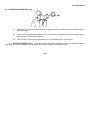
1
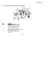
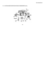
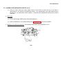
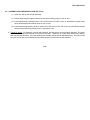
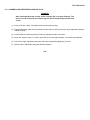
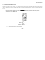
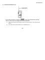
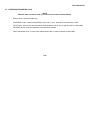
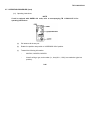
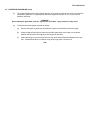
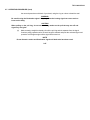
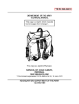
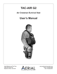
TM 1-1680-359-10
OPERATORS MANUAL
AIRCREW SURVIVAL ARMOR
RECOVERY VEST, INSERT,
AND PACKETS
(SARVIP)
DISTRIBUTION STATEMENT A
Approved for public release
distribution is unlimited
HEADQUARTERS
DEPARTMENT OF THE ARMY
22 MAY 1992
TM 1-1680-359-10
WARNING
FLIGHT OPERATIONS WHILE WEARING SARVIP
Prior to flight operations in any aircraft, aviators/aircrew members must ensure that the SARVIP
vest and ballistic insert do not cause interference with flight controls, weapons systems
operation, or restrict performance of in flight duties.
WARNING
RESTRAINT HARNESS
The SARVIP vest is not designed to be used in lieu of the gunner/hoist operator restraint
harness. Use of SARVIP only will not provide restraint to the aircraft. Don the restraint harness
over the SARVIP vest and ensure security of harness tether during flight operations.
WARNING
ARMOR INSERT
Ensure carrier's closure flap is securely fastened. The armor insert is heavy and could injure
legs and feet if inadvertently dropped.
a
TM 1-1680-359-10
WARNING
LIFT PREPARATION
Ensure vest slide fastener is engaged and fully closed and waist and chest adjustment straps are
properly fastened to provide a snug fit prior to personnel lift operation.
WARNING
SMOKE AND ILLUMINATION SIGNAL
Don't light both ends of a signal at the same time. Be careful when using the illumination
signal, as drippings from the burning signal can cause serious burns on the body.
WARNING
TRIOXAME COMPRESSED FUEL
Fuel contains metaformaldehyde, which is highly toxic. Don't put hands near mouth or eyes
after handling opened or leaking packages. Wash hands immediately.
For first aid procedures, refer to FM 21-11.
b
TM 1-1680-359-10
TECHNICAL MANUAL
No.
HEADQUARTERS
DEPARTMENT OF THE ARMY
Washington, D C., 22 May 1992
1-1680-359-10
Operator's Manual
AIRCREW SURVIVAL ARMOR RECOVERY
VEST, INSERT, AND PACKETS
REPORTING ERRORS AND RECOMMENDING IMPROVEMENTS
You can help improve this manual If you find any mistakes or if you
know of a way to improve the procedures, please let us know Mall
your letter or DA Form 2028 (Recommended Changes to Publications and Blank Forms), direct to Commander, U S Army Aviation
Systems Command, ATTN AMSAV-MC, 4300 Goodfellow
Boulevard, St Louis, MO 63120-1798 A reply will be furnished to
you.
TABLE OF CONTENTS
CHAPTER 1
Section I
Section II
Page
INTRODUCTION
General Information ................................................. 1-1
Equipment Description............................................. 1-2
DISTRIBUTION STATEMENT A: Approved for public release; distribution is unlimited.
i
TM 1-1680-359-10
TABLE OF CONTENTS (Cont)
Page
CHAPTER 2
OPERATING INSTRUCTIONS
Section I
Description and Use of
Operator's Controls s
and Indicators. ................................................... 2-1
Section II
Preventive Maintenance
Checks and Services
(PMCS) ............................................................. 2-9
Section III
Operation Under Usual
Conditions ......................................................... 2-19
Section IV
Operation Under Unusual
Conditions ......................................................... 2-48
CHAPTER 3
MAINTENANCE INSTRUCTIONS.................................. 3-1
APPENDIX A
REFERENCES .............................................................. A-1
INDEX....................................................................................................................................................... I-1
ii
TM 1-1680-359-10
CHAPTER 1
INTRODUCTION
Section I. GENERAL INFORMATION
1-1. SCOPE. This manual is for your use when, as an air-crew member, you are required to use the Aircrew Survival
Armor Recovery Vest, Insert, and Packets (SARVIP). The purpose of this manual is to provide you with a description of
the components and instructions on their intended use and care.
1-2. MAINTENANCE FORMS AND PROCEDURES. Department of the Army forms and procedures used for equipment
maintenance will be those prescribed by DA Pam 738-751, Functional User's Manual for the Army Maintenance
Management System Aviation (TAMMS-A).
1-3. REPORTING EQUIPMENT IMPROVEMENT RECOMMENDATIONS (EIR'S). If your SARVIP needs improvement,
let us know. Send us an EIR. You, the user, are the only one who can tell us whale you don't like about your equipment.
Let us know why you don't like the design or performance. Put it on an SF 368 (Product Quality Deficiency Report). Mail
It to us at. Commander, U S Army Aviation Systems Command, ATTN AMSAV-QRF, 4300 Goodfellow Boulevard, St
Louis MO 63120-1798. We will send you a reply.
1-1
TM 1-1680-359-10
1-4. DESTRUCTION OF ARMY NATERIEL TO PREVENT ENEMY USE. Procedures for destroying Army materiel to
prevent enemy use are listed in TM 750-244-3.
Section II. EQUIPMENT DESCRIPTION
1-5. EQUIPMENT CHARACTERISTICS, CAPABILITIES, AND FEATURES.
The Aircrew Survival Armor Recovery Vest, Insert, and Packets (SARVIP) is a three part system: survival vest,
armor insert with carrier, and survival, signal and communication components.
Vest. The vest Is fabricated from raschel knit and fire resistant aramid oxford fabrics. It contains a total of twelve
pockets; ten outer and two inner. Together these pockets house all survival, signal and communication components. For
rescue-lift, a nylon webbing harness system is permanently attached to the vest in a cradle fashion and contains both leg
and chest straps. The chest strap also provides the means for attaching the LPU/10 life preservers. The vest also
provides means for attaching a motor housing and face mask carrier when wearing MOPP clothing.
Insert. The armor insert consists of a laminated ceramic/fiberglass composite backed with a 3/4 inch thick foam
padding. The foam padding provides blunt trauma protection when
1-2
TM 1-1680-359-10
1-5. EQUIPMENT CHARACTERISTICS, CAPABILITIES, AND FEATURES (Cont)
struck with small arms fire. A fire resistant aramid oxford fabric carrier with seven layers of Kevlar (R) is provided to
carry the insert. The Kevlar (R) provides the necessary spall protection from the insert when the insert is impacted with a
round. A cradle type harness arrangement on the carrier is used for holding the insert on the body. A quick release strap
located on the bottom of the carrier allows the insert to be jettisoned during emergencies.
Survival Signal and Communication Components. Placed in the various pockets on the vest are the following
items: compass, mirror, smoke and Illumination flares, sea dye marker, distress light marker, chemical agent detectors,
distress signal kit, operators manual, and survival packets consisting of medical and basic components necessary for
survival.
A pocket is also provided on the vest for carrying a PRC-90 or PRC-112 radio. Operation of the AN/PRC-90 or
AN/PRC-112 will span a wide range of weather extremes. Although the radio circuits are operable over a temperature
range of -30°to +500C (-22°to +1220F), the battery power supply is only effectively operable over a 0°to +54°C (+32°
to +1290F) temperature range. Operating at low temperature reduces battery life. The radio may be stored over a
temperature range of -60°to +60°C (-76°to +1400F).
1-3
TM 1-1680-359-10
1-6. LOCATION AND DESCRIPTION OF MAJOR COMPONENTS
Item
1
2
Description
BODY ARMOR INSERT. A ceramic/
fiberglass armor insert with foam
padding providing ballistic and blunt
trauma protection from small arms
fire up to 12.7 MM (.50 CAL).
BODY ARMOR INSERT CARRIER. Aramid
oxford fabric carrier with seven
layers of Kevlar (R) used to carry
armor insert.
1-4
TM 1-1680-359-10
1-6. LOCATION AND DESCRIPTION OF MAJOR COMPONENTS (Cont)
Item
Description
3
TYPEI(BASIC)SURVIVAL PACKET.A sealed polyethylene bag containing basic items necessary for
survival.
4
LENSATIC COMPASS. Used to determine the direction of travel.
5
VEST. Raschel knit and oxford fire resistant fabric that contains survival components.
6
EMERGENCY SIGNALING MIRROR. Used to signal aircraft or other targets.
7
TYPE II (MEDICAL) SURVIVAL PACKET.A sealed polyethylene bag containing medical items
necessary for survival.
8
DISTRESS MARKER LIGHT. Produces intermittent flash of light visible for minimum of 5 miles.
9
SEA DYE MARKER. Fluorescein dye for location in water.
10
OPERATOR'S MANUAL. Provides instruction for use and maintenance of vest and components.
1-5
TM 1-1680-359-10
1-6. LOCATION AND DESCRIPTION OF MAJOR COMPONENTS (Cont)
1-6
TM 1-1680-359-10
1-6. LOCATION AND DESCRIPTION OF MAJOR COMPONENTS (Cont)
Item
Description
11
FOLIAGE PENETRATING SIGNAL KIT. Consists of a rocket launcher and seven red flares.
12
CHEMICAL DETECTOR PAPER. Used to detect presence of nuclear, biological, or chemical
agents.
13
TYPE IV SURVIVAL PACKET. A sealed polyethylene bag containing a combat casualty blanket.
14
TYPE III SURVIVAL PACKET. A sealed polyethylene bag containing a first aid dressing and water
storage bag.
15
AN/PRC-90 OR AN/PRC-112 RADIO. Used to transmit and receive radio messages.
16
MK-24 SMOKE AND ILLUMINATION FLARES. Daytime or nighttime signal for rescue.
17
LPU-10/P LIFE PRESERVERS. Inflatable life preservers.
1-7
TM 1-1680-359-10
1-7. DIFFERENCES BETWEEN MODELS. There are no component or capability differences between the various sized
models.
1-8. EQUIPMENT DATA.
a Armor Insert.
Length
(inches)
Short
Medium
Long
X-Long
9.8
11.1
12.5
12.9
Top
Width
(inches)
Bottom
Width
(inches)
Weight
(pounds)
8.6
9.4
9.2
10.1
11.5
12.5
12.8
12.9
9.2
10.9
13.5
13.9
b. Vest
Chest
(inches)
X-Small
Small
Medium
Large
X-Large
Under 33
33 - 37
37 - 41
41 - 45
Over 45
Waist
(inches)
Under 27
27 - 31
31 - 35
35 - 39
Over 39
1-8
TM 1-1680-359-10
CHAPTER 2
OPERATING INSTRUCTIONS
Section I. DESCRIPTION AND USE OF
OPERATOR'S CONTROLS AND INDICATORS
2-1. CONTROLS AND INDICATORS. The only controls and indicators are on the radio set, AN/PRC-90.
Control or
Key Indicator
1
Function
Switch
(fourposition
rotary
switch)
Function
Selects transceiver operating
mode and turns radio off.
2-1
TM 1-1680-359-10
2-1. CONTROLS AND INDICATORS (Cont)
Control or
Key Indicator
Function
1
Function Switch (Cont)
Switch Position:
OFF
Removes power from radio set.
VOICE 282.8
Turns receiver on for reception of 282.8 MHz voice signals and permits 282.8 MHz voice
transmission when PUSH TO TALK button is pressed. (Function switch button must be pressed
to place switch in this position.)
2-2
TM 1-1680-359-10
2-1. CONTROLS AND INDICATORS (Cont)
Control or
Key Indicator
1
Function
Function Switch (Cont)
BCN 243.0
Turns on 243.0 MHz transmitter and transmits a beacon tone. Swept audio tone is continuously
transmitted for rescue aircraft to home on. Voice reception and transmission cannot be used
in this mode.
VOICE/MCW
Turns receiver on for reception of 243.0 MHz voice or MCW signals. Also permits 243.0 MHz
voice or MCW transmission when keyed by PUSH TO TALK or MCW buttons.
2-3
TM 1-1680-359-10
2-1. CONTROLS AND INDICATORS (Cont)
Control or
Key Indicator
2
Function
Switch
Arrow/
PUSH TO TALK
Pushbutton
Function
Indicates operational mode
selected and locks out VOICE
282.8 position unless pressed.
When it is pressed, it turns
receiver off and turns transmitter on when function switch
is in either VOICE/MCW 243.0
or VOICE 282.8 position. Best
voice transmission is obtained
when spoken directly into the
TALK microphone. When the button is released, it turns off
the transmitter and turns on
the receiver; received signal
is heard from the LISTEN
speaker or earphone.
2-4
TM 1-1680-359-10
2-1. CONTROLS AND INDICATORS (Cont)
Key
3
Control or
Indicator
MCW Button
Function
Can be used as a telegraph key to transmit morse code when normal voice transmission may
reveal operator's position. MCW is only available when function switch is in the VOICE/MCW
243.0 position. When MCW button is pressed, radio set transmits continuous tone and
receiver is off. When button is released, transmitter is turned off and receiver is turned on.
2-5
TM 1-1680-359-10
2-1. CONTROLS AND INDICATORS (Cont)
2-6
TM 1-1680-359-10
2-1. CONTROLS AND INDICATORS (Cont)
Key
Control or
Indicator
Function
4
VOL Control
Controls sound level from LISTEN speaker or earphone. Controls received signals, not
sidetone. When control is in MAX position, greatest level of sound is heard; when fully turned
down, lowest level of sound is heard, but radio set is not turned off. Control setting does not
affect transmitter output.
5
Antenna
Receptacle
Provides connection for radio set antenna.
6
EARPHONE
JACK
Provides connection for ear phone. When earphone is connected, LISTEN speaker is
shut off and sound is heard from earphone.
7
LISTEN
Speaker
Projects sound of received signal; sound of MCW or beacon transmitter (sidetone)
may also be projected. LISTEN speaker is shut off when earphone is connected.
2-7
TM 1-1680-359-10
2-1. CONTROLS AND INDICATORS (Cont)
Control or
Key Indicator
Function
8
TALK
Microphone
Picks up voice being transmitted when PUSH TO TALK button is pressed and
function switch is set to VOICE/MCW 243.0 or VOICE 282.8 position.
9
Battery Cap
Holds battery in place and externally seals battery compartment.
2-8
TM 1-1680-359-10
Section II. PREVENTIVE MAINTENANCE
CHECKS AND SERVICES (PMCS)
2-2. INTRODUCTION
a. General. Table 2-1 (PMCS Table) has been provided so you can keep your equipment in good operating
condition and ready for its primary mission.
b. Warnings and Cautions. Always observe the WARNINGS and CAUTIONS appearing in your PMCS table.
WARNINGS and cautions appear before applicable procedures. You must observe these WARNINGS and CAUTIONS
to prevent serious injury to yourself and others or prevent your equipment from being damaged.
c. Explanation of Table Entries.
(1) Item number column. Numbers in this column are for reference. When completing DA Form 2404
(Equipment Inspection and Maintenance Worksheet), include the item number for the check/service indicating a fault.
(2) Interval column. This column tells you when you must do the procedure in the procedure column.
BEFORE procedures must be done before you operate or use the equipment for its intended mission. AFTER
procedures must be done immediately after you have operated or used the equipment.
2-9
TM 1-1680-359-10
2-2. INTRODUCTION (Cont)
(3) Location, check/service column.
serviced. The item location is underlined.
This column provides the location and the item to be checked or
(4) Procedure column. This column gives the procedure you must do to check or service the item listed in the
Check/Service column to know if the equipment is ready or available for its intended mission or for operation. You must
do the procedure at the time stated in the interval column.
(5) Not fully mission capable if: column. Information in this column tells you what faults will keep your
equipment from being capable of performing its primary mission. If you make check and service procedures that
show faults listed in this column, do not operate the equipment. Follow standard operating procedures for maintaining
the equipment or reporting equipment failure.
d. Other table entries. Be sure to observe all special information and notes that appear in your table.
2-3. SPECIAL INSTRUCTIONS.
a. The sealed packets are exempt from opening for inspection. The packets are sealed in a NBC protective film
with air evacuated.
2-10
TM 1-1680-359-10
2-3. SPECIAL INSTRUCTIONS (Cont)
The components within have been individually sealed in a plastic material. Each packet contains an inventory
list of components for use when the packet is opened.
b. The medical packet has a separate inventory list of medical components that have a potency expiration. This list
contains the nomenclature, manufacturer, date of manufacture, and expiration date.
2-11
TM 1-1680-359-10
Table 2-1. Preventive Maintenance
Checks and Services for SARVIP
Item
No.
Interval
Location
Item to
Check/
Service
Procedure
Not Fully Mission
Capable if:
NOTE
PMCS Item numbers correspond to
figure numbers on page 1-4.
1
Before
and
After
Body
Armor
Insert
Check insert
for chips or
other damage.
Insert damaged.
2
Before
and
After
Armor
Insert
Carrier
Check for dirt
or foreign
material,
tears, loose
or broken
stitching;
defective adj properly.
straps, quick
release strap
or closure
flap; broken
or cracked
side-release
buckles.
Carrier
severely
torn or
flap torn
or not
functioning
2-12
TM 1-1680-359-10
Table 2-1. Preventive Maintenance
Checks and Services for SARVIP
Item
No.
Interval
Location
Item to
Check/
Service
Procedure
Not Fully Mission
Capable if:
NOTE
PMCS Item numbers correspond to
figure numbers on pages 1-4 and
1-6.
3,
7,
13,
14
Before
and
After
Packets
Check for cuts,
tears, water
exposure,
packets not
sealed,
missing bro
ken or leaks,
dates of medical items.
Seals broken or
items missing or
items broken or
leaking or
medical
items expired.
4
Before
and
After
Lensatic
Compass
Check for broken or cracked dial face
cover, operation, and
original
stowed position.
Dial face
cover broken or
cracked or
compass not
operable.
2-13
TM 1-1680-359-10
Table 2-1. Preventive Maintenance
Checks and Services for SARVIP
Item
No.
Interval
Location
Item to
Check/
Service
Procedure
Not Fully Mission
Capable if:
NOTE
PMCS Item numbers correspond to figure
numbers on page 1-4.
5
Before
and
After
Vest
Check for cuts,
tears, holes,
burns, broken
or loose
stitching/
hardware/
straps/tape,
defective
fasteners or
snaplink carabiner.
Vest severely torn,
any damage
to rescuelift harness and/or
components.
6
Before
and
After
Emergency Signalling
Mirror
Check for distortion,
chips, cracks
or scratches,
unreadable
Instructions,
broken/missing lanyard.
Mirror
broken.
2-14
TM 1-1680-359-10
Table 2-1. Preventive Maintenance
Checks and Services (Cont’d)
Item
No.
Interval
Location
Item to
Check/
Service
Procedure
Not Fully Mission
Capable if:
NOTE
PMCS Item numbers correspond to figure
numbers on page 1-4.
8
Before
and
After
Distress
Marker
Light
and
Flashguard
Check for broken/cracked
light lens or
flashguard,
light operation.
Light does
not operate or
broken
flashguard.
9
Before
and
After
Sea Dye
Marker
Check for cuts
or holes or
tears in
packet, broken/missing
retainer
tape, packet
opening tape
not sealed
completely,
instruction
markings illegible.
Packet torn
or marker
leaking.
2-15
TM 1-1680-359-10
Table 2-1. Preventive Maintenance
Checks and Services for SARVIP
Item
No.
Interval
Location
Item to
Check/
Service
Procedure
Not Fully Mission
Capable if:
NOTE
PMCS Item numbers correspond to figure
numbers on pages 1-4 and 1-6.
10
Before
and
After
Operator
Manual
Check for torn
or missing or
illegible
pages, dampness.
Pages
missing or
illegible.
11
Before
and
After
Foliage
Penetrating
Signaling Kit
Check for damage, rust,
dirt, corrosion, or other
foreign material, operation of trigger screw,
damaged/missing retainer
cord, damaged
or corroded
or leaking
flares.
Severely
damaged,
leaking
flares.
2-16
TM 1-1680-359-10
Table 2-1. Preventive Maintenance
Checks and Services for SARVIP
Item
No.
Interval
Location
Item to
Check/
Service
Procedure
Not Fully Mission
Capable if:
NOTE
PMCS Item numbers correspond to figure
numbers on page 1-6.
12
Before
and
After
Chemical
Detector
Paper
Check for cuts
or holes or
tears in
packet,
instruction
markings,
packet expiration date.
Pack torn,
illegible
instructions, or
expired
contents.
15
Before
and
After
AN/PRC90 or
AN/PRC112
Radio
Check for damage, perforated seals,
presence of
salt/oil/sand
accumulation,
condition of
earphone and
case, and set
operation.
Structure
severely
damaged or
set does
not operate
2-17
TM 1-1680-359-10
Table 2-1. Preventive Maintenance
Checks and Services for SARVIP
Item
No.
Interval
Location
Item to
Check/
Service
Procedure
Not Fully Mission
Capable if:
NOTE
PMCS Item numbers correspond to figure
numbers on page 1-6.
16
Before
and
After
MK-24
Smoke
and
Illumination
Flare
Check for damage, severe
dents,
deformity,
broken seals.
Seals
broken.
17
Before
and
After
LPU-10/P
Life
Preserver
Check for cuts
or tears or
abrasions,
torn stitches
or other damage to containers,
safety tie on
release pins,
stains, dirt
and general
cleanliness.
Containers
damaged.
2-18
TM 1-1680-359-10
Section III. OPERATION UNDER USUAL CONDITIONS
2-4. GENERAL. This section provides instructions for wear and use of the SARVIP under normal operating conditions.
2-5. ASSEMBLY AND PREPARATION FOR USE
a. Fitting Armor. To ensure the proper armor insert is selected, individuals must do the following.
(1) Sit erect as shown; adjust feet to ensure that upper thighs are on a horizontal plane.
(2) With upper arms hangingrelaxed, extend forearms and hands forward horizontally.
(3) Place a 4-inch block of wood across your lap so that it is close to the body and in a horizontal position.
2-19
TM 1-1680-359-10
2-5. ASSEMBLY AND PREPARATION FOR USE (Cont)
(4) Select an armor insert that, when placed vertical on the block of wood, the top of the insert is
approximately 1 inch below the suprasternale location. (The suprasternale is the small indenture above
the sternum.) An insert which comes closest to 1 inch below the suprasternale location is your correct
insert size.
b. Fitting Vest.
(1) Put on required flight, MOPP and/or cold weather garments.
(2) Select a vest based on your measurements (refer to paragraph 1-8 for vest sizes available).
c. Attaching LPU-1O/P Life Preservers. The illustration below shows proper placement of LPU.
2-20
TM 1-1680-359-10
2-5. ASSEMBLY AND PREPARATION FOR USE (Cont)
(1) Open vest and lay flat (outside exposed).
(2) Extract chest strap from right pocket tunnel and three retaining loops on rear of vest.
(3) Insert strap through retaining loops of LPU-10/P (ensure LPU-10/P is face up with inflation lanyard facing
down) and through three retaining loops on rear of vest.
(4) Insert strap through retaining loops of second LPU-10/P (ensure LPLI-10/P is face up with inflation lanyard
facing down) and through pocket tunnel on right side of vest.
d. Putting On Armor. For maximum comfort and protection, the body armor must be properly adjusted. The insert
must be worn straight and centered on the front of the chest. Twisted or off center armor affects body balance
and interferes with activities. For proper balance, the shoulder straps must be adjusted evenly. Armor should be
snug but not too tight, as overtightening may inhibit the armor insert quick-release capability.
2-21
TM 1-1680-359-10
2-5. ASSEMBLY AND PREPARATION FOR USE (Cont)
WARNING
After inserting body armor, ensure carrier's closure flap is securely fastened. The
armor insert is heavy and could injure legs and feet if inadvertently released from
carrier.
(1) Insert armor into carrier and fasten carrier's closure flap securely.
(2) Engage adjustment strap buckles (located at bottom sides of carrier) and open carrier adjustment straps to
maximum length.
(3) Insert head and arms through loops formed by adjustment straps and carrier.
(4) Raise and support armor to rest on chest with top of armor approximately 1 inch below suprasternale.
(5) Pull left and right adjustment strap tabs until armor is adjusted (slightly taut) to chest.
(6) Secure ends of adjustment straps with attached keepers.
2-22
TM 1-1680-359-10
2-5. ASSEMBLY AND PREPARATION FOR USE (Cont)
e. Putting On Vest.
(1) Unfasten vest's waist sizing strap at rear and don vest.
(2) Engage and fully close slide fastener.
NOTE
Waist adjustment strap should be snug but not too tight. Overtightening may prohibit quick
release of the armor insert.
(3) Fasten and adjust waist adjustment straps at rear of vest.
(4) Fasten and adjust the chest strap until snug: return excess strap through right pocket tunnel and fasten
with attached keeper.
(5) Attach snap-link carbine through the rescue-lift loops located on both sides of vest near top of slide
fastener.
(6) Check for proper fit/adjustment of armor and vest by bending, stooping, and kneeling. Adjust as needed.
2-23
TM 1-1680-359-10
2-5. ASSEMBLY AND PREPARATION FOR USE (Cont)
f. Attaching Leg Webbing.
(1) Release the leg webbing straps from their keepers at rear of vest.
NOTE
Leg webbings are not crossed: ensure webbing straps
webbing to left V-ring and right webbing to right V-ring.
are not twisted and attach left
(2) Pass leg webbing straps through the crotch (from rear to front) and attach webbing strap snap ejectors to
the vest V-rings.
2-24
TM 1-1680-359-10
2-5. ASSEMBLY AND PREPARATION FOR USE (Cont)
NOTE
For freedom of movement, perform leg strap tightness adjustment after seated in aircraft.
(3) Adjust webbings for taut fit by pulling on free strap ends; fasten excess strap ends with attached keepers.
2-25
TM 1-1680-359-10
2-5. ASSEMBLY AND PREPARATION FOR USE (Cont)
g. Taking Off Vest.
(1) Detach leg strap snap ejectors from the vest -ring.
(2) Detach snap-link carabiner from one rescue-lift-loop.
(3) Unfasten chest strap.
(4) Disengage slide fastener.
(5) Take off vest.
h. Taking Off Armor.
WARNING
Support carrier and armor insert while disengaging carrier strap buckles and taking off
armor. The armor insert is heavy and could injure legs and feet if inadvertently dropped.
(1) While supporting armor, disengage carrier strap buckles located at bottom sides of carrier.
(2) While supporting armor, take off the carrier by removing head from loop formed by carrier straps.
2-26
TM 1-1680-359-10
2-6. INITIAL ADJUSTMENTS, DAILY CHECKS, AND SELF-TEST
a.
Perform before operation PMCS.
b.
Check for proper fit by bending, stooping, and kneeling. Adjust as needed.
2-7. OPERATING PROCEDURE. The following provides instructions on the operation and use of the vest, armor and
all survival, signal, and communication devices used with or provided by the SARVIP.
WARNING
FLIGHT OPERATIONS WHILE WEARING SARVIP
Prior to flight operations in any aircraft, aviators/air crew members must insure that the
SARVIP vest and ballistic insert do not cause interference with flight controls, weapons
systems operation, or restrict performance of in-flight duties.
2-27
TM 1-1680-359-10
2-7. OPERATING PROCEDURE (Cont)
WARNING
RESTRICTION OF MOVEMENT
Certain size individuals, in certain aircraft, may experience an aft cyclic movement restriction
and/or experience reach restrictions during aircraft starting when wearing the vest and
ballistic insert. Failure to ensure freedom of movement could endanger your life.
WARNING
RESTRAINT HARNESS
The SARVIP vest is not designed to be used in lieu of the gunner/hoist operator restraint
harness. Failure to put on the restraint harness over the SARVIP vest and ensure security of
harness tether during flight operations could endanger your life.
a.
SURVIVAL VEST AND ARMOR. For use and wear of the vest and armor, refer to paragraph 2-6d through
2-6h.
2-28
TM 1-1680-359-10
2-7. OPERATING PROCEDURE (Cont)
b.
BASIC (TYPE I) SURVIVAL PACKET. The basic packet should remain sealed until it is required to be used.
Use items sparingly to make sure they last until you are rescued.
Item
1
2
3
4
5
6
7
8
9
10
11
12
Description/Use or Operation
COMPRESSED TRIOXANE FUEL. Use for
heating food and/or water.
WATERPROOF MATCHES. For use as
required.
WHISTLE. Use for signaling or
communication and aid in rescue.
MAGNESIUM FIRE STARTER. Use for instant
fire starting.
HEADNET AND MITTEN SET. Use for protection against insects (apply insect
repellent before using).
SUNSCREEN AND INSECT REPELLENT. Use for
protection against insects and sunburn.
HAND-SAW, TYPE MB-2. Use in shelter
construction or for other use as
required.
POCKETKNIFE. For use as required.
MOLESKIN. Use for foot injuries and
blisters.
CHEWING GUM. Use for quick energy.
CANDY. Use for quick energy and body
nourishment.
LIST OF CONTENTS AND INSTRUCTIONS. Use
for item identification, inventory, and
usage instructions.
2-29
TM 1-1680-359-10
2-7. OPERATING PROCEDURE (Cont)
c.
MEDICAL (TYPE II) SURVIVAL PACKET. The medical packet should remain sealed until it is required to
be used. Use items sparingly to make sure they last until you are rescued.
Item
1
2
3
4
5
6
7
8
9
10
11
12
13
14
Description/Use or Operation
ASPIRIN TABLETS. Use for relief of
headache and acute pain.
ADHESIVE BANDAGES. Use to bandage minor
cuts and skin breaks.
GAUZE BANDAGES. Use for sterile
protection of wounds or cuts.
BACITRACIN OINTMENT. Use as a salve for
protection of cuts, scratches, bites and
fungus infections.
BACITRACIN OPTHALMIC EYE OINTMENT. Use
to treat eye injuries and irritations.
DENTAL FLOSS. Use for cleaning teeth.
ANTI-DIARRHEA IMODIUM CAPSULES. Use for
relief of diarrhea.
SAFETY PINS. Use to help secure
bandages, slings and clothing.
SURGICAL PREPARATION RAZOR. Use to
shave hair and to open wounds.
ADHESIVE TAPE. Use to close wounds and
help secure bandages.
SCOPOLINE DISCS. Use to ease motion
sickness.
SEWING NEEDLES. Use for mending
clothing and webbing.
PENROSE TUBING. Use to control blood
circulation and flow.
SOAP. Use for cleansing wounds.
2-30
TM 1-1680-359-10
2-7. OPERATING PROCEDURE (Cont)
Item
15
16
Description/Use or Operation
WATER PURIFICATION TABLETS. Use for
purifying water.
LIST OF CONTENTS AND INSTRUCTIONS. Use
for item identification, inventory, and
usage instructions.
d.
TYPE III SURVIVAL PACKET. The first aid dressing and water storage bag packet should remain sealed
until it is required to be used.
Item
1
2
3
Description/Use or Operation
FIRST AID FIELD DRESSING. Use to protect wounds and as compress to stop
bleeding.
WATER STORAGE BAG. Use for storing and
carrying water.
LIST OF CONTENTS AND INSTRUCTIONS. Use
for item identification, inventory, and
usage instructions.
e.
TYPE IV SURVIVAL PACKET. The combat casualty blanket packet should remain sealed until it is required
to be used.
Item
1
2
Description/Use or Operation
COMBAT CASUALTY BLANKET. Use for
protection from cold.
LIST OF CONTENTS AND INSTRUCTIONS. Use
for item identification, inventory, and
usage instructions.
2-31
TM 1-1680-359-10
2-7. OPERATING PROCEDURE (Cont)
f.
LENSATIC COMPASS. The lensatic compass has a solid aluminum body hinged in the center to permit the
body bottom to fold over the compass face. It is locked by the thumb ring; this secures the magnetic needle and protects
the face from damage when not in use.
The compass consists of a front and rear sight, a stationary index, a moveable bezel ring with a luminous lubber line,
luminous sighting dots, a lens in the rear sight, a thumb ring, and a graduated straight edge. To use the compass,
proceed as follows:
NOTE
The arrow on the compass dial always points to magnetic "NORTH".
2-32
TM 1-1680-359-10
2-7. OPERATING PROCEDURE (Cont)
NOTE
Items which contain iron or steel, or other types of compasses, will cause the lensatic
compass to give incorrect readings.
(1)
Hold the compass erect so that the lubber line is parallel to your line of sight:
(2)
Turn the plastic top until the lubber line is over the NORTH arrow. Your course heading may then
be read on a line drawn through the sights.
g.
EMERGENCY SIGNALING MIRROR. The signal mirror is a glass signaling instrument equipped with a
retaining cord on one corner and a see-through sighting device in the center of the glass. When used in daytime and
with good visibility, a mirror flash can be seen at a distance of 30 miles at an altitude of 10,000 feet. Though less
effective, and with possible shorter range, mirror flashes can also be seen on cloudy days with limited visibility. To use
the mirror, proceed as follows:
2-33
TM 1-1680-359-10
2-7. OPERATING PROCEDURE (Cont)
(1)
Hold mirror in a manner which will allow the sunlight to reflect on a nearby surface such as the hand or
other close object.
(2)
Bring mirror up to eye level and using one eye, look through the sighting device until an intense bright
spot is located. This is the aim indicator.
(3)
Hold the mirror close to the eye and slowly turn it until the bright spot is on the target.
h.
DISTRESS MARKER LIGHT. The distress marker light, when activated, produces an Intermittent flash of
light visible for a minimum distance of 5 miles and will operate completely submerged in water.
2-34
TM 1-1680-359-10
2-7. OPERATING PROCEDURE (Cont)
(1)
The marker light also has a flashguard which may be used for directional aiming of the light. The
flashguard is equipped with a blue lens so that flashes can be distinguished from gunfire flashes. Use
flashguard with the distress marker light when in a combat zone.
(2)
Check the marker light for operation before departing on a mission. The batteries screw into the
bottom of the light case; no spare batteries are provided with the SARVIP.
i.
SEA DYE MARKER. The sea dye marker is used for location when in water. To operate, open packet and
pull tab to release the dye.
2-35
TM 1-1680-359-10
2-7. OPERATING PROCEDURE (Cont)
j.
FOLIAGE PENETRATING SIGNAL KIT.
The signal kit consists of a rocket launcher and seven red flares. Flares can reach an altitude of 1100 feet when fired
and have a burning time of 9 seconds. Flares are visible for 2 or 3 miles in daylight and for up to 10 miles at night. To
use the flares, proceed as follows:
WARNING
Do not point a loaded launcher at personnel. Distress flares burn at a temperature of 5000
degrees F and can cause serious burns or death.
(1)
Remove flare from plastic retainer and insert flare into launcher.
2-36
TM 1-1680-359-10
2-7. OPERATING PROCEDURE (Cont)
CAUTION
After flare is in launcher, do not pull back on knurled knob unless you are ready to fire flare.
Do not fire towards or lead the aircraft. Serious damage can result if aircraft is hit by flare,
thereby hampering your rescue.
(2)
Hold projector firmly in hand, point it straight up and pull knurled knob down with thumb.
(3)
Release trigger with a sharp sudden motion.
k.
CHEMICAL DETECTOR PAPER. When there is a chance that you are exposed to a nuclear, biological, or
chemical (NBC) agent, use the detector packet. Open packet and follow the instructions inside.
l.
AN/PRC-90 RADIO. The battery provided will operate the radio approximately 30 hours at 68 degrees F or
15 hours at 32 degrees F on a duty cycle of approximately 50 percent transmit and 50 percent receive. Range of radio
for line-of-sight operation is approximately 30 miles for
2-37
TM 1-1680-359-10
2-7. OPERATING PROCEDURE (Cont)
homing and 10 miles for voice contact. For maximum transmit and receive, keep hands away from antenna when the
radio is in operation and hold in a vertical position with the antenna pointed straight up. Perform the following steps prior
to use.
WARNING
Leave the function switch in the OFF position. Unauthorized personnel shall not perform
maintenance on the AN/PRC-90.
(1)
Unscrew battery cap and remove battery.
2-38
TM 1-1680-359-10
2-7. OPERATING PROCEDURE (Cont)
(2)
Check manufacture date stamped on battery. Maximum shelf life is 3 years in temperate climates. If
over 3 years old, discard.
(3)
Check for evidence of battery leakage or corrosion.
(4)
Check condition of copper spring contacts.
(5)
Install a new battery if required. Battery only goes in one way.
(6)
Screw battery cap on fingertight.
2-39
TM 1-1680-359-10
2-7. OPERATING PROCEDURE (Cont)
CAUTION
Be sure radio set antenna is installed and telescopic sections fully extended before operating
radio set. Failure to do so can damage radio operating capabilities.
(7)
Check receiver operation by releasing the antenna from stored position. Fully extend telescopic
sections.
(8)
Set function switch to either VOICE 282.8 or VOICE/MCW 243.0.
2-40
TM 1-1680-359-10
2-7. OPERATING PROCEDURE (Cont)
NOTE
Proper receiver operation will be indicated by a slight hissing sound in the MAX position.
(9)
Set VOL control to MAX position.
NOTE
Presence of squealing, "motor-boating", or other abnormal sound (other than normal AM
static interference) is an indication of malfunction.
(10) If abnormal static is heard, turn function switch to OFF position.
CAUTION
Do not operate MCW PUSH TO TALK switches. Damage to radio may result without the
antenna installed.
(11) Check for evidence of obvious structural damage such as cracked case, perforated seals, or presence
of salt or oil accumulations.
2-41
TM 1-1680-359-10
2-7. OPERATING PROCEDURE (Cont)
(12) Check for presence of earphone and check earphone case and cover.
(13) Replace antenna in stored position.
NOTE
Radio set AN/PRC-90 is used only for emergency (and/or tactical) communications. The radio
can be expected to perform properly, assuming normal maintenance has been kept current.
The following operational modes are available:
2-42
TM 1-1680-359-10
2-7. OPERATING PROCEDURE (Cont)
NOTE
With the radio on beacon mode, you cannot receive voice communications.
°
Beacon mode. Uses 243.0 MHz only.
°
VOICE/MCW mode. Used for transmitting morse code or voice. Instructions on back plate of radio.
°
VOICE mode. Used for two-way transceiver communications with air, sea, or ground radios on 243.0 MHz.
282.8 MHz can be used as an alternate voice channel as directed.
°
VOICE 282.8 MHz mode. Push function switch arrow button in order to operate on 282.8 MHz.
2-43
TM 1-1680-359-10
2-7. OPERATING PROCEDURE (Cont)
(14) Operating instructions:
NOTE
If unit is equipped with AN/PRC-112 radio, refer to accompanying TB 11-5820-1037-10 for
operating instructions.
(a)
Pull antenna all the way out.
(b)
Rotate four-position rotary switch to VOICE/MCW 243.0 position.
(c)
Transmit the following information:
°
MAYDAY, MAYDAY, MAYDAY
°
Aircraft call sign, type, and number (i.e., Army UH-1, 1234), has crashed at (give last
position).
2-44
TM 1-1680-359-10
2-7. OPERATING PROCEDURE (Cont)
(d)
Broadcast the above information for 5 seconds. Then listen for 5 seconds. If no answer or
aircraft can be heard in your vicinity, switch to beacon mode (BCN).
NOTE
Do not point tip of antenna at rescue aircraft when transmitting.
m.
(e)
At 15 minutes before the hour and 15 minutes after the hour, repeat steps 3 and 4.
(f)
If aircraft is ELT equipped, use survival radio for voice transmission only.
MK-24 SMOKE AND ILLUMINATION FLARE.
(1)
The smoke signal is a hand-actuated day or night distress signal. One end of the signal contains
orange smoke for daytime and the opposite end (flare end) contains a pyrotechnic composition for
illumination during nighttime use. The Illumination end can be identified by a series of embossed
projections located 1/4 inch below the end cap.
2-45
TM 1-1680-359-10
2-7. OPERATING PROCEDURE (Cont)
(2)
The average burning time of the nighttime signal is 18 seconds and can be seen for 2 to 3 miles from
an altitude of 3000 feet. During day-time, the smoke signal can be seen for 2 to 3 miles from an
altitude of 3000 feet.
WARNING
Do not attempt to ignite both ends of a signal at the same time. Injury from burns may result.
(3)
To activate the smoke signal, proceed as follows:
(a)
Remove the paper or plastic cap from either the smoke or illumination end of the signal.
(b)
Grasp the signal firmly with one hand and hold the signal close to the chest in a horizontal
position with each end of the signal pointed away from the body.
(c)
Insert index finger of your free hand into pull ring, which should break the soldered end of cap
free. If soldered cap does not release, bring the pull ring down over the rim of
2-46
TM 1-1680-359-10
2-7. OPERATING PROCEDURE (Cont)
the can and press down with heel of your hand, using the ring as a lever to break the seal.
WARNING
Be careful using the illumination signal. Drippings from the burning signal can cause serious
burns on the body.
CAUTION
When pulling on the pull ring, do not use a twisting motion as the pull tab may tear off and
signal may not ignite.
(d)
Make a steady, straight horizontal pull until the pull ring and tab separate from the signal.
Continue pulling upwards until a full arm's length is reached and point the activated signal end
upward at a 45 degree angle until the signal has burned out.
NOTE
Do not discard a smoke and illumination signal until both ends have been used.
2-47
TM 1-1680-359-10
2-7. OPERATING PROCEDURE (Cont)
(e)
If only one end of signal is used immerse that end only in oil or water to cool. Dry carefully and
place signal back in original packing.
n.
LPU-1O/P LIFE PRESERVER. Once the aircrew member has cleared the aircraft, the following procedure
should be performed following a water landing.
WARNING
Do not initiate LPU-10/P inflation procedures until clear of aircraft as personnel injury may
result.
(1)
Inflate underarm life preservers by pulling sharply downward and slightly outward on lanyard that
extends from lower front corner of each cell. If cells are not fully inflated, use oral inflation valve and
fully inflate cells.
(2)
Fasten cells together with the fasteners located on the front of the cells.
2-48
TM 1-1680-359-10
Section IV. OPERATION UNDER UNUSUAL CONDITIONS
2-8. DESERT REGIONS. Before using the equipment, remove all sand and dust.
2-9. TROPICAL REGIONS. In climates of high humidity, inspect the equipment daily for fungus, mold, insects, and
metallic corrosion.
2-10. ARCTIC REGIONS.
a.
Before using the equipment, remove all snow and ice.
b.
Equipment operated at low temperatures should be kept in low temperature storage when not in use. Store
the equipment in a shipping carton and cover the carton with water-repellant material (SB 38-100).
c.
When operational conditions using Battery BA-1568/UR include temperatures below 50°F, the radio set and
spare battery should be carried inside flight clothing to prevent cold soaking. The battery will not supply
sufficient power to operate the radio if cold soaked for extended periods of time at or below freezing
temperatures with a battery that has been prewarmed. Batteries should be warmed as soon as possible after
exposure to ensure reliable
2-49
TM 1-1680-359-10
2-10. ARCTIC REGIONS (Cont)
operation of the radio. The following table shows the maximum operating time for cold weather use of the
batteries.
Temperature (°F)
+32
0
-40
Operating Time
30 minutes
15 minutes
5 minutes
2-11. OPERATION IN MARITIME OR RAINY AREAS. Keep SARVIP and associated components in a dry area if
possible.
2-12. RECOGNITION AND IDENTIFICATION OF JAMMING.
a.
Under tactical conditions, the AN/PRC-90 or AN/ PRC-112 carried by the crewmember may be jammed by
the enemy. The jamming may be planned or accidental and will usually be caused by a strong signal
transmitted on the same frequency as that being used. The signal being transmitted may be a steady carrier
or a modulated carrier.
b.
When it becomes difficult or impossible to receive the desired signal, switch the function switch to the
alternate voice channel or revert from the voice to the MCW mode and attempt CW contact.
2-50
TM 1-1680-359-10
2-13. EMERGENCY PROCEDURES. Follow these procedures if your aircraft is in water.
1
Clear safely from aircraft.
2
Eject armor insert as follows:
(a)
Pull carrier's quick-release tab/strap until carrier is open.
(b)
Simultaneously grasp bottom of vest (pulling away from body) and bottom of insert.
(c)
Inhale and pull down on insert to release from carrier.
(d)
Discard insert.
3
Inflate LPU-10/P (para 2-8n).
4
Use signal/communication devices.
5
Prepare for rescue/emergency lift by ensuring that:
(a)
Vest slide fastener is fully engaged.
(b)
Snap-link carabiner is properly installed through both rescue lift loops.
(c)
Adjustment straps at chest, waist and legs provide snug fit.
2-51
TM 1-1680-359-10
2-13. ENERGENCY PROCEDURES (Cont)
6
Upon arrival of rescue aircraft, attach rescue/lift cable fastener through your vest's snap-release carabiner for
lift.
2-52
TM 1-1680-359-10
CHAPTER 3
MAINTENANCE INSTRUCTIONS
3-1. General. Keep the vest and armor clean and in usable condition. Improper wear may result in less protection and
comfort. Careless handling or use of the vest for purposes other than flight operations should be avoided.
3-2. SARVIP Care.
a.
Follow cleaning instructions provided on labels attached to vest and armor insert carrier. They may be
washed using warm, soapy water, rinsed in clean water and allowed to drip-dry.
WARNING
Be sure to turn in damaged vest. Failure to do so could endanger your life.
b.
Do not attempt repairs to the vest/harness or ballistic insert carrier. Turn in the damaged item to your ALSE
technician for repair or replacement.
c.
Turn in and have replaced immediately any damaged or outdated survival items.
3-1
TM 1-1680-359 10
3-2. SARVIP Care (Cont)
WARNING
Be sure to turn in damaged ballistic insert. Failure to do so could endanger your life.
d.
Turn in a damaged ballistic insert immediately to your ALSE technician.
3-2
TM 1-1680-359-10
APPENDIX A
REFERENCES
A-1. SCOPE. This appendix lists all forms, field manuals, technical manuals, and miscellaneous publications
referenced in this manual.
A-2. REFERENCES
Functional Users Manual for the
Army Maintenance Management
System - Aviation (TAMMS-A)........................................................................................................DA Pam 738-751
First Aid for Soldiers ........................................................................................................................................... FM 21-11
Aviation Unit and Aviation Intermediate Maintenance Manual with
Repair Parts and Special Tool
List for Army Aircraft Survival
Kits ........................................................................................................................................ TM 55-1680-317-23&P
Preservation, Packaging, Packing
and Marking Materials, Supplies
and Equipments Listed by the
Army.........................................................................................................................................................SB 38-100
Recommended Changes to Equipment
Publications and Blank Forms.............................................................................................................DA Form 2028
Quality Deficiency Report........................................................................................................................................ SF 368
A-1
TM 1-1680-359-10
A-2. REFERENCES (Cont)
Equipment Inspection and Maintenance Worksheet..................................................................................................................................DA Form 2404
Procedures for Destruction of
Army Materiel to Prevent Enemy
Use..................................................................................................................................................... TM 750-244-3
Operation of AN/PRC-112.................................................................................................................. TB 11-5820-1037-10
A-2
TM 1-1680-359-10
INDEX
Subject
Page
A
Adhesive Bandages ............................................................................................................................... 2-30
Adhesive Tape ....................................................................................................................................... 2-30
AN/PRC-90 Radio Transmitter/Receiver ................................................................................................ 1-7
AN/PRC-112 Radio Transmitter/Receiver .............................................................................................. 1-7
Antenna Receptacle ............................................................................................................................... 2-7
Anti-diarrhea Imodium Capsules ............................................................................................................ 2-30
Armor (see "Body Armor Insert")
Aspirin Tablets ....................................................................................................................................... 2-30
Assembly and Preparation for Use ......................................................................................................... 2-19
B
Bacitracin Ointment................................................................................................................................ 2-30
Bacitracin Opthalmic Eye Ointment........................................................................................................ 2-30
Battery Cap............................................................................................................................................ 2-8
Battery Installation
Radio............................................................................................................................................ 2-38
Distress Light Marker .................................................................................................................... 2-35
BCN 243.0 ............................................................................................................................................. 2-3
Blanket, Combat Casualty...................................................................................................................... 2-31
Body Armor Insert
Description ................................................................................................................................... 1-4
Emergency Release ..................................................................................................................... 2-51
Fitting ........................................................................................................................................... 2-19
Inspection ..................................................................................................................................... 2-12
Putting On .................................................................................................................................... 2-21
Sizes ............................................................................................................................................ 1-8
Taking Off .................................................................................................................................... 2-26
Index-1
TM 1-1680-359-10
INDEX (Cont)
Subject
Page
C
Candy .................................................................................................................................................... 2-29
Carrier, Armor Insert
Description ................................................................................................................................... 1-4
Inspection ..................................................................................................................................... 2-12
Putting On .................................................................................................................................... 2-21
Taking Off .................................................................................................................................... 2-26
Chemical Detector Paper
Description ................................................................................................................................... 1-7
Inspection ..................................................................................................................................... 2-17
Operation ..................................................................................................................................... 2-37
Cleaning Instructions (SARVIP).............................................................................................................. 3-1
Compass, Lensatic
Description ................................................................................................................................... 1-5
Inspection ..................................................................................................................................... 2-13
Operation ..................................................................................................................................... 2-32
D
Dental Floss ........................................................................................................................................... 2-30
Description and Use of Operator's
Controls and Indicators ................................................................................................................. 2-1
Destruction of Army Material to
Prevent Enemy Use...................................................................................................................... 1-2
Differences Between Models .................................................................................................................. 1-8
Index 2
TM 1-1680-359-10
INDEX (Cont)
Subject
Page
E
Earphone Jack, Radio ............................................................................................................................ 2-7
Emergency Procedures .......................................................................................................................... 2-51
Equipment Characteristics,
Capabilities, and Features ............................................................................................................ 1-2
Equipment Data ..................................................................................................................................... 1-8
F
First Aid Field Dressing .......................................................................................................................... 2-31
Flare, Smoke and Illumination, MK-24
Description ................................................................................................................................... 1-7
Inspection ..................................................................................................................................... 2-18
Operation ..................................................................................................................................... 2-45
Fuel, Compressed Trioxane ................................................................................................................... 2-29
Function Switch, Radio........................................................................................................................... 2-1
G
Gauze Bandages.................................................................................................................................... 2-30
Gum, chewing ........................................................................................................................................ 2-29
H
Headnet ................................................................................................................................................. 2-29
Index 3
TM 1-1680-359-10
INDEX (Cont)
Subject
Page
I
Initial Adjustments, Daily Checks,
and Self-Test ................................................................................................................................ 2-27
Insect Repellent ..................................................................................................................................... 2-29
Insert (see "Body Armor Insert)
Inspection, SARVIP................................................................................................................................ 2-9
Introduction ............................................................................................................................................ 1-1
K
Knife, Pocket.......................................................................................................................................... 2-29
L
Leg Webbing.......................................................................................................................................... 2-24
Light, Distress Marker
Description ................................................................................................................................... 1-5
Inspection ..................................................................................................................................... 2-15
Operation ..................................................................................................................................... 2-34
Location and Description of Major
Components ................................................................................................................................. 1-4
LPU-10/P Life Preserver
Description ................................................................................................................................... 1-7
Inspection ..................................................................................................................................... 2-18
Installation .................................................................................................................................... 2-20
Operation ..................................................................................................................................... 2-48
Index 4
TM 1-1680-359-10
INDEX (Cont)
Subject
Page
M
Magnesium Fire Starter Bar ................................................................................................................... 2-29
Maintenance Forms and Procedures ...................................................................................................... 1-1
Maintenance Procedures, SARVIP......................................................................................................... 3-1
Matches, Waterproof.............................................................................................................................. 2-29
MCW Button, Radio ............................................................................................................................... 2-5
Microphone, Radio ................................................................................................................................. 2-8
Mirror, Emergency Signaling
Description ................................................................................................................................... 1-5
Inspection ..................................................................................................................................... 2-14
Operation ..................................................................................................................................... 2-33
Mittens ................................................................................................................................................... 2-29
O
Operating and Storage Limitations,
Radio............................................................................................................................................ 1-3
Operator's Manual
Description ................................................................................................................................... 1-5
Inspection ..................................................................................................................................... 2-16
Operating Under Usual Conditions ......................................................................................................... 2-19
Operation Under Unusual Conditions
Arctic Regions .............................................................................................................................. 2-49
Desert Regions ............................................................................................................................. 2-49
Maritime or Rainy Areas ............................................................................................................... 2-50
Tropical Regions........................................................................................................................... 2-49
Index 5
TM 1-1680-359-10
INDEX (Cont)
Subject
Page
P
Packet, Survival, Type I
Contents ....................................................................................................................................... 2-29
Description ................................................................................................................................... 1-5
Inspection ..................................................................................................................................... 2-13
Packet, Survival, Type II
Contents ....................................................................................................................................... 2-30
Description ................................................................................................................................... 1-5
Inspection ..................................................................................................................................... 2-13
Packet, Survival, Type III
Contents ....................................................................................................................................... 2-31
Description ................................................................................................................................... 1-7
Inspection ..................................................................................................................................... 2-13
Packet, Survival, Type IV
Contents ....................................................................................................................................... 2-31
Description ................................................................................................................................... 1-7
Inspection ..................................................................................................................................... 2-13
Penrose Tubing...................................................................................................................................... 2-30
PUSH-TO-TALK Button, Radio .............................................................................................................. 2-4
Preventive Maintenance Checks
and Services (PMCS) ................................................................................................................... 2-9
R
Radio Operation..................................................................................................................................... 2-37
Modes of Operation
Beacon Mode ...................................................................................................................... 2-43
Voice/MCW Mode ............................................................................................................... 2-43
Voice Mode ......................................................................................................................... 2-43
Index 6
TM 1-1680-359-10
INDEX (Cont)
Subject
Page
Radio Transmitter/Receiver, AN/PRC-90
Description ................................................................................................................................... 1-7
Inspection ..................................................................................................................................... 2-17
Operation ..................................................................................................................................... 2-37
Radio Transmitter/Receiver, AN/PRC-112 ............................................................................................ 1-7
Recognition and Identification of
Jamming ...................................................................................................................................... 2-50
Reporting Equipment Improvement
Recommendations (EIR'S)............................................................................................................ 1-1
Reporting Errors and Recommending
Improvements .............................................................................................................................. i
S
Safety Pins............................................................................................................................................. 2-30
Saw, Flexible ......................................................................................................................................... 2-29
Scope .................................................................................................................................................... 1-1
Scopoline Discs...................................................................................................................................... 2-30
Sea Dye Marker
Description ................................................................................................................................... 1-5
Inspection ..................................................................................................................................... 2-15
Operation ..................................................................................................................................... 2-35
Sewing Needles ..................................................................................................................................... 2-30
Signal Kit, Foliage Penetrating
Description ................................................................................................................................... 1-7
Inspection ..................................................................................................................................... 2-16
Operation ..................................................................................................................................... 2-36
Index 7
TM 1-1680-359-10
INDEX (Cont)
Subject
Page
Smoke and Illumination Flare, MK-24
Description ................................................................................................................................... 1-7
Inspection ..................................................................................................................................... 2-18
Operation ..................................................................................................................................... 2-45
Soap ..................................................................................................................................................... 2-30
Speaker, Radio ...................................................................................................................................... 2-7
Special Instructions ................................................................................................................................ 2-10
Sunscreen and Insect Repellent ............................................................................................................. 2-29
Surgical Preparation Razor .................................................................................................................... 2-30
V
Voice 28243. .......................................................................................................................................... 2-2
Voice/MCW 243.0 .................................................................................................................................. 2-3
VOL Control ........................................................................................................................................... 2-7
Vest, Survival
Characteristics.............................................................................................................................. 1-2
Description ................................................................................................................................... 1-5
Fitting ........................................................................................................................................... 2-20
Inspection ..................................................................................................................................... 2-14
Operation ..................................................................................................................................... 2-28
Putting On .................................................................................................................................... 2-23
Sizes ............................................................................................................................................ 1-8
Taking Off .................................................................................................................................... 2-26
W
Washing Instructions, SARVIP ............................................................................................................... 3-1
Water Purification Tablets...................................................................................................................... 2-31
Water Storage Bag ................................................................................................................................ 2-31
Whistle................................................................................................................................................... 2-29
Index 8
The Metric System and Equivalents
Linear Measure
Liquid Measure
1 centiliter = 10 milliters = .34 fl. ounce
1 deciliter = 10 centiliters = 3.38 fl. ounces
1 liter = 10 deciliters = 33.81 fl. ounces
1 dekaliter = 10 liters = 2.64 gallons
1 hectoliter = 10 dekaliters = 26.42 gallons
1 kiloliter = 10 hectoliters = 264.18 gallons
1 centimeter = 10 millimeters = .39 inch
1 decimeter = 10 centimeters = 3.94 inches
1 meter = 10 decimeters = 39.37 inches
1 dekameter = 10 meters = 32.8 feet
1 hectometer = 10 dekameters = 328.08 feet
1 kilometer = 10 hectometers = 3,280.8 feet
Square Measure
Weights
1 sq. centimeter = 100 sq. millimeters = .155 sq. inch
1 sq. decimeter = 100 sq. centimeters = 15.5 sq. inches
1 sq. meter (centare) = 100 sq. decimeters = 10.76 sq. feet
1 sq. dekameter (are) = 100 sq. meters = 1,076.4 sq. feet
1 sq. hectometer (hectare) = 100 sq. dekameters = 2.47 acres
1 sq. kilometer = 100 sq. hectometers = .386 sq. mile
1 centigram = 10 milligrams = .15 grain
1 decigram = 10 centigrams = 1.54 grains
1 gram = 10 decigram = .035 ounce
1 decagram = 10 grams = .35 ounce
1 hectogram = 10 decagrams = 3.52 ounces
1 kilogram = 10 hectograms = 2.2 pounds
1 quintal = 100 kilograms = 220.46 pounds
1 metric ton = 10 quintals = 1.1 short tons
Cubic Measure
1 cu. centimeter = 1000 cu. millimeters = .06 cu. inch
1 cu. decimeter = 1000 cu. centimeters = 61.02 cu. inches
1 cu. meter = 1000 cu. decimeters = 35.31 cu. feet
Approximate Conversion Factors
To change
To
inches
feet
yards
miles
square inches
square feet
square yards
square miles
acres
cubic feet
cubic yards
fluid ounces
pints
quarts
gallons
ounces
pounds
short tons
pound-feet
pound-inches
centimeters
meters
meters
kilometers
square centimeters
square meters
square meters
square kilometers
square hectometers
cubic meters
cubic meters
milliliters
liters
liters
liters
grams
kilograms
metric tons
Newton-meters
Newton-meters
Multiply by
To change
2.540
.305
.914
1.609
6.451
.093
.836
2.590
.405
.028
.765
29,573
.473
.946
3.785
28.349
.454
.907
1.356
.11296
ounce-inches
centimeters
meters
meters
kilometers
square centimeters
square meters
square meters
square kilometers
square hectometers
cubic meters
cubic meters
milliliters
liters
liters
liters
grams
kilograms
metric tons
To
Newton-meters
inches
feet
yards
miles
square inches
square feet
square yards
square miles
acres
cubic feet
cubic yards
fluid ounces
pints
quarts
gallons
ounces
pounds
short tons
Temperature (Exact)
°F
Fahrenheit
temperature
5/9 (after
subtracting 32)
Celsius
temperature
°C
Multiply by
.007062
.394
3.280
1.094
.621
.155
10.764
1.196
.386
2.471
35.315
1.308
.034
2.113
1.057
.264
.035
2.205
1.102
U.S. GPO: 1992-756-100
PIN: 070540-000
This fine document...
Was brought to you by me:
Liberated Manuals -- free army and government manuals
Why do I do it? I am tired of sleazy CD-ROM sellers, who take publicly
available information, slap “watermarks” and other junk on it, and sell it.
Those masters of search engine manipulation make sure that their sites that
sell free information, come up first in search engines. They did not create it...
They did not even scan it... Why should they get your money? Why are not
letting you give those free manuals to your friends?
I am setting this document FREE. This document was made by the US
Government and is NOT protected by Copyright. Feel free to share,
republish, sell and so on.
I am not asking you for donations, fees or handouts. If you can, please
provide a link to liberatedmanuals.com, so that free manuals come up first in
search engines:
<A HREF=http://www.liberatedmanuals.com/>Free Military and Government Manuals</A>
– Sincerely
Igor Chudov
http://igor.chudov.com/