1
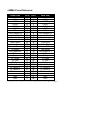
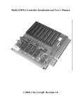
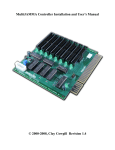
MultiJAMMA Switchboard Installation and User’s Manual
© 2000, Clay Cowgill Revision 1.0
Notice Regarding this Kit
Warning!
Although this kit has been tested and the techniques used
will not directly cause harm to your video games, if you
do something wrong you can very seriously damage the
game electronics!
To perform this kit installation you should:
• Be familiar with safe handling procedures for electronic components.
• Be able to remove and install new power supplies without causing damage.
• Be able to build cable harnesses for power and (optionally) control inputs.
• Be able to follow directions.
Arcade games are rugged equipment, but anytime you start messing around with something (particularly
something electronic) you accept a certain amount of risk that you may break something.
This kit carries with it no guaranty of compatibility to your particular game. Although this kit has been
tested with numerous JAMMA game boards it is possible that there are JAMMA boards that are
incompatible. If you carefully follow these instructions, you should do fine and everything should work. If
you feel the complexity of this system is beyond your ability to install, please hire someone local to you to
perform the installation. Due to the custom nature of every installation, technical support from
Multigame.com is limited to kit behavior only.
Please read these instructions completely through before starting. If at any point you become lost of
confused, please consider hiring someone to perform the installation for you. One reversed power
connection and you’ll have a dead game board(s) and a damaged MultiJAMMA! Because of the risk of
“user error”, this kit is sold AS-IS. It has been tested and works 100% when shipped, but if anything
happens to it that requires repair it IS NOT a free service. Repair rates for the MultiJAMMA Controller
start at $15 plus $7 return shipping. Repair rates for the MultiJAMMA Switchboards start at $9 plus $7
return shipping. Be careful!
By using this kit you agree to the following terms and conditions:
Multigame.com makes no warranties on the MultiJAMMA, expressed, implied, statutory, or in any other
communication with you. Multigame.com specifically disclaims any implied warranty of merchantability
or fitness for a particular purpose. Multigame.com does not warrant that the operation of the
MultiJAMMA will be uninterrupted or error free. In no event will Multigame.com or any supplier of the
MultiJAMMA be liable to you or any other person or entity for any damages, including any incidental or
consequential damages, expenses, lost profits, lost savings, or other damages arising out of the use of or
inability to use the MultiJAMMA even if Multigame.com have been advised of the possibility of such
damages. This kit is provided AS-IS. By using the MultiJAMMA you agree to the above terms and
conditions. If you choose not to abide by these terms you must return the MultiJAMMA to the place of
purchase within 7 days of receiving it for a full refund, less any restocking fees and shipping/handing
expenses.
Table of Contents:
TABLE OF CONTENTS:.....................................................................................................................................................3
INTRODUCTION:................................................................................................................................................................4
SWITCHBOARD FEATURES: ...........................................................................................................................................4
SWITCHBOARD CONNECTIONS: ...................................................................................................................................4
“DISK DRIVE” / STANDARD POWER CONNECTOR (A): ............................................................................................................5
HIGH-CURRENT / ALL VOLTAGE POWER CONNECTOR (B): .......................................................................................................5
GAME SELECTED LED (C):...................................................................................................................................................5
SPARE INPUT CONNECTOR (D): .............................................................................................................................................5
40 PIN CONNECTORS FOR CABLE TO MULTIJAMMA CONTROLLER (E): ..................................................................................6
FREE-PLAY JUMPER SETTINGS (F): .........................................................................................................................................6
JAMMA CARD-EDGE CONNECTOR (G): ................................................................................................................................6
SETTING UP AND USING THE SWITCHBOARD: .........................................................................................................6
POWER-ON TEST:..............................................................................................................................................................7
TROUBLESHOOTING: ......................................................................................................................................................7
ANYTIME YOU SUSPECT AN ERROR, ALWAYS CHECK THE FOLLOWING FIRST: ............................................................................7
DIM PICTURE ON MONITOR. ...................................................................................................................................................7
MONITOR DISPLAY ROLLS OR WON’T SYNC. ...........................................................................................................................8
GAME GRAPHICS MESSED UP/GAME DOESN’T DISPLAY PICTURE................................................................................................8
NO SOUND, OR POOR QUALITY SOUND....................................................................................................................................8
YOU’RE FINISHED!............................................................................................................................................................8
JAMMA PINOUT REFERENCE: .......................................................................................................................................9
Introduction:
The MultiJAMMA system is designed to allow up to eight JAMMA standard arcade game boards to be connected in a single
cabinet and allow easy electronic switching between the games with the push of a button.
A MultiJAMMA installation will consist of a MultiJAMMA Controller and anywhere from two to eight MultiJAMMA
Switchboards. The Controller coordinates switching between the games while the Switchboards handle the actual electrical
signal routing. Switchboards connect to the MultiJAMMA Controller by a 40 pin ribbon cable. JAMMA Game boards plug
into the Switchboards and the MultiJAMMA Controller plugs into the JAMMA harness in the arcade game cabinet.
Because most arcade game power supplies are designed to run a single arcade game board, you will need to add additional
power supplies to the game cabinet to power all of the boards.
Switchboard Features:
•
Quick and easy connection to JAMMA (and other) standard games.
•
LED indicator to show when game is selected.
•
Uses standard PC "IDE" hard-drive cables making it easy to customize cable lengths if the included cables don't fit your
needs.
•
Super-high reliability relays and digital switches route video and audio signals.
•
Power connections support direct connection to economical PC power supplies.
•
Relays rated at a minimum of 5,000,000 switches (that's switching games continuously 24 hours a day, once every minute
for 9.5 years!).
Switchboard Connections:
G
F
A
E
D
B
C
A = “disk drive” type power connector
B = High-current / all voltage power connector
C = Game selected LED
D = Spare input connector
E = 40 pin connector for cable to MultiJAMMA Controller
F = Free-play setting jumpers
G = JAMMA Card-edge connector
“Disk Drive” / Standard Power Connector (A):
This connector is a standard “PC” hard-drive/floppy drive power connector. If your JAMMA game board only requires +5V
and +12V power you may use this connector to easily attach the switchboard to a standard “PC” power supply. Some game
boards may draw more current than can be reliably delivered by this connector—if the power cables to this connector get
warm (or hot) or if there is any scorching or discoloration of the switchboard circuit board or connector, switch to using the
High-current connector instead! Remember that it is critical that all power supplies are connected to the same ground
reference.
+12V DC
Ground
Ground
+5V DC
Front, Top Down
View
High-Current / all voltage power connector (B):
This connector includes +5V, +12V, and the -5VDC power supply connections. It is capable of handling higher current loads
than the “disk drive” power connector and should be used with JAMMA game boards that draw large amounts of power. The
pinout of the connector is designed such that plugging a power harness in backwards will not be catastrophic—it will
however result in the -5VDC supply not being connected. Remember that it is critical that all power supplies are connected
to the same ground reference.
8
1
Ground
+5VDC
+12VDC
no connection
-5VDC
+12VDC
+5VDC
Game Selected LED (C):
Ground
This LED will light when the switchboard is connected to the MultiJAMMA Controller and the game slot that the 40-pin
cable is connected to is selected.
Spare Input Connector (D):
The spare input connector provides a ground pin and four additional input lines that go to each Switchboard. If you are going
to use games with more than the standard JAMMA buttons you can wire up additional buttons through this connector.
6
“Expand”
1
1 = spare input 1
2 = spare input 2
3 = spare input 3
4 = spare input 4
5 = No Connection
6 = Signal Ground
40 pin connectors for cable to MultiJAMMA Controller (E):
This connector goes to the MultiJAMMA Controller. Switchboards come with cables and are keyed to prevent inserting them
backwards. If longer cables are necessary for your particular installation you may use standard “PC” IDE Hard-drive cables.
Note that longer cables (or poor quality short cables) can effect video and audio quality in some cases.
Free-play jumper settings (F):
The Switchboard can support a variety of free-play settings for game boards in conjunction with the MultiJAMMA Controller
board.
= Jumper Off Pins
2
1
6
5
= Jumper On Pins
= Jumper On or OFF
With the MultiJAMMA Controller set to coin-operated mode, this setting is used.
The game will accept coins to play.
Mode
2
1
6
5
With the MultiJAMMA Controller set to free-play mode, this setting is used to select
“phantom coin” mode. The MultiJAMMA Controller will give an imaginary “coin”
to the game when start is pressed. This allows free-play on older games without a
free-play setting.
6
5
With the MultiJAMMA Controller set to free-play mode, this setting is used if the
JAMMA game board is ALSO set to free-play (no coins required). The MultiJAMMA
Controller will simply start the game when start is pressed. No coins (imaginary or
otherwise) are sent to the game board in this mode.
Mode
2
1
Mode
JAMMA Card-edge connector (G):
This is where the Switchboard connects to the JAMMA game board. Note that the connector is NOT keyed (so as to work
with clone/bootleg JAMMA boards that are missing the “notch” in the edge connector). The Switchboard plugs onto the
JAMMA game board “parts side up”. The cable and parts on the Switchboard should be on the same side as the chips and
parts on the JAMMA board with the edge connector. Note that the Switchboard does have the “KEY” location labeled in
white by the power connector—check that it lines up with the “key” on the game board connector if it’s present. If in doubt,
seek professional assistance! Do NOT plug the switchboard onto the JAMMA connector backwards! Bad things can/will
happen to your JAMMA board and possibly the MultiJAMMA system and/or your power supplies.
Setting up and using the Switchboard:
1.
To use the switchboard with your MultiJAMMA Controller board, simply connect one end of the 40 pin ribbon cable to
the next available slot on the MultiJAMMA Controller. (Start adding cables and Switchboards starting on slot 1 on the
MultiJAMMA Controller.) Connect the other end of the 40 pin cable to the Switchboard.
2.
Set the Free-play jumpers on the Switchboard according to you particular installation needs. Remember that Free-play
settings only take effect if the MultiJAMMA Controller is also configured for Free-play.
3.
Connect the power supply to the appropriate power connector (either the “disk drive” type connector or the “high
current” connector). Be sure that all power supply grounds are all connected together.
4.
Double-check your power connector wiring! Refer to the JAMMA pinout at the end of this document and verify that
your power connections will send power to the correct pins.
5.
Make sure that the MultiJAMMA Controller is configured to support the proper number of Switchboards you have
connected.
6.
Check your power connections. Again. Really. You do not want these to be wrong!
Power-on test:
At this point, if you’ve triple-checked your power supply wiring you should be confident that everything is hooked up 100%
correct. Plug in a single game board (ideally something cheap and easily replaced—just in case you’ve made a mistake) and
turn on the system. The MultiJAMMA Controller should have it’s power LED light. If the game board has a power LED it
should light as well. Press the game-select switch (either on the MultiJAMMA Controller or where you placed it on the
cabinet) repeatedly until the LED on the Switchboard being tested lights. This means the game is selected and it should
appear on the monitor screen. Sound and all controls should be functional at this point.
Check the power supply voltages on the game board and at the power supplies to make sure everything is running as it
should. If all voltages look good you can power down the system and repeat the installation for additional Switchboards.
Troubleshooting:
The MultiJAMMA Switchboard is tested prior to shipment, so a hardware problem is relatively unlikely. Certain installation
errors can create situations that may look like a hardware fault.
Anytime you suspect an error, always check the following first:
•
•
•
•
•
Check voltages at the game board and at several points on the board, all should be within +/-10% of their specified
value.
Are all power supplies connected by common grounds?
Is everything plugged in? (Obvious, but you’d be surprised how many times this causes problems!)
Test the cabinet with the MultiJAMMA unplugged and a known working JAMMA board to verify that the monitor,
speakers, and controls all work properly.
If you’re using cables that did not come with the kit—are they oriented properly?
Dim picture on monitor.
Make sure that all the game boards are supplied with power and ground and that all grounds are common (connected together
somewhere). Test game boards without the MultiJAMMA in line to make sure it’s not a monitor problem. If you’re using
IDE cables that did not come with the kit they could be too long, or too fine of gauge wire and are degrading the video signal.
Monitor display rolls or won’t sync.
Is the monitor a fixed-scan monitor? The MultiJAMMA system can not automatically adjust sync rates. Test game boards
without the MultiJAMMA in line to make sure it’s not a monitor problem. If you’re using IDE cables that did not come with
the kit they could be too long, or too fine of gauge wire and are degrading the video signal.
Game graphics messed up/game doesn’t display picture.
Are you supplying -5V to the game board by way of the “High-Current” connector on the Switchboard? Some games will
need -5V for proper video output and to pass self-test. Test game boards without the MultiJAMMA in line to make sure it’s
not a board problem.
No sound, or poor quality sound.
Are you supplying -5V to the game board by way of the “High-Current” connector on the Switchboard? Some games will
need -5V for proper audio output. Test game boards without the MultiJAMMA in line to make sure it’s not a speaker or board
problem. If you’re using IDE cables that did not come with the kit they could be too long, or too fine of gauge wire and are
degrading the audio signal.
Game won’t select.
Make sure that the number of games selected on the MultiJAMMA Controller matches the number of Switchboards you have
connected. If in doubt, turn the power off, set the MultiJAMMA Controller to eight-games, turn the power back on and press
the game select button 10 or 12 times. You should see the Switchboard selected at least once. If not, check that the 40 pin
cable is plugged in all the way and both ends are connected. Swap it with another (preferably known working) Switchboard
cable to see if the problem follows the cable of the Switchboard.
You’re Finished!
At this point, you should have a successfully installed Switchboard with your MultiJAMMA. Repeat this procedure for any
additional Switchboards and enjoy your MultiJAMMA System.
JAMMA Pinout Reference:
Solder Side
GND
GND
+5VDC
+5VDC
-5VDC
+12VDC
- KEY Coin Counter # 2
Lock Out Coil # 2
Speaker (-)
Video Green
Video Sync
Service Switch
Tilt Switch
Coin Switch # 2
2P Start
2P Up
2P Down
2P Left
2P Right
2P Button 1
2P Button 2
2P Button 3
2P Button 4
GND
GND
Pin #
A
B
C
D
E
F
H
J
K
L
M
N
P
R
S
T
Y
V
W
X
Y
Z
a
b
c
d
e
f
Pin #
1
2
3
4
5
6
7
8
9
10
11
12
13
14
15
16
17
18
19
20
21
22
23
24
25
26
27
28
Parts Side
GND
GND
+5VDC
+5VDC
-5VDC
+12VDC
- KEY Coin Counter # 1
Lock Out Coin # 2
Speaker (+)
Video Red
Video Blue
Video GND
Test Switch
Coin Switch # 1
1P Start
1P Up
1P Down
1P Left
1P Right
1P Button 1
1P Button 2
1P Button 3
1P Button 4
GND
GND
(signals in “italic” are not supported on the MultiJAMMA.)