1
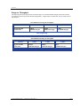
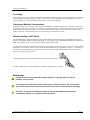
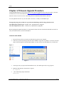
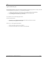
Ffirm ATLAS4900 Point-to-Point Wireless OFDM Ethernet Bridge USER MANUAL June, 2007 Revision 1.3 Table of Contents Trango Table of Contents Preface.................................................................................................................................................................. iii FCC Information .......................................................................................................iii Warranty Information ...............................................................................................iii Chapter 1 Overview................................................................................................................................................3 Range vs. Throughput .............................................................................................. 3 System Contents ...................................................................................................... 3 Location of Serial Number & MAC Address.................................................................. 3 Location of RJ-45/LED Port........................................................................................ 3 Chapter 2 Getting Started .......................................................................................................................................3 Connections and Power............................................................................................. 3 Configuration Tools................................................................................................... 3 Troubleshooting Ethernet Connections ....................................................................... 3 System Information (sysinfo) Page ............................................................................ 3 Chapter 3 Configuration .........................................................................................................................................3 Key Concepts ........................................................................................................... 3 Essentials to Establish a Wireless Link ........................................................................ 3 Master Unit Configuration.......................................................................................... 3 Remote Unit Configuration ........................................................................................ 3 Establishing a Wireless Link....................................................................................... 3 Changing IP Address................................................................................................. 3 LEDs ........................................................................................................................ 3 RF Link Loopback Test (linktest command)................................................................. 3 Link Speed & Power Settings ..................................................................................... 3 Command Reference Listing ...................................................................................... 3 Chapter 4 Deployment & Installation.....................................................................................................................3 Site Selection ........................................................................................................... 3 Site survey ............................................................................................................... 3 Channel Planning...................................................................................................... 3 RSSI Command and Antenna Alignment..................................................................... 3 Mounting Hardware .................................................................................................. 3 Grounding ................................................................................................................ 3 Cabling and Weather Considerations .......................................................................... 3 Weather Sealing on EXT Model .................................................................................. 3 Weatherizing............................................................................................................ 3 Chapter 5 SNMP ....................................................................................................................................................3 Chapter 6 Firmware Upgrade Procedure ................................................................................................................3 Appendix A Using the HTTP Interface...........................................................................................................3 Appendix B Specifications..............................................................................................................................3 Trango Broadband Wireless — Atlas4900 User Manual Rev. 1.3 page ii Preface Preface This manual covers the basic configuration and installation of the ATLAS4900 Wireless Point to Point Broadband System, and applies to the following radio part numbers: P4900M-INT-18 P4900M-INT-22 P4900M-EXT Atlas4900-INT18 point-to-point radio with integrated 18 dBi panel antenna Atlas4900-INT22 point-to-point radio with integrated 22 dBi panel antenna Atlas4900-EXT point-to-point radio with external h/v polarization antenna connectors The ATLAS4900-INT-18 and –INT-22 products consist of two radios which have either internal 18 or 22 dBi antennas with electronically selectable polarization. The –EXT radios are designed for use with external dish antennas. All three products contain universal power adapters and mounting hardware for a pole. This device requires professional installation and a license. FCC Information This device complies with Part 90 of the FCC Rules and Regulations. This equipment has been tested and found to comply with the limits for a Class B digital device, pursuant to Part 15 of the FCC Rules. These limits are designed to provide reasonable protection against harmful interference in a residential installation. This equipment generates, uses, and can radiate radio-frequency energy and, if not installed and used in accordance with these instructions, may cause harmful interference to radio communications. However, there is no guarantee that interference will not occur in any particular installation. If this equipment does cause harmful interference to radio or television reception, which can be determined by turning the equipment off and on, the user is encouraged to correct the interference by one of more of the following measures: 1) 2) 3) 4) Reorient the antenna. Increase the separation between the affected equipment and the unit. Connect the affected equipment to a power outlet on a different circuit from that which the receiver is connected to. Consult the dealer and/or experienced radio/TV technician for help. FCC ID: NCYP4900M IMPORTANT NOTE: Intentional or unintentional changes or modifications must not be made unless under the express consent of the party responsible for compliance. Any such modifications could void the user’s authority to operate the equipment and will void the manufacturer’s warranty. To comply with FCC RF exposure requirements, the following antenna installation and device operating configurations must be satisfied. The antenna for this unit must be fixed and mounted on outdoor permanent structures with a separation distance of at least two meters from all persons. Furthermore, it must not be colocated or operating in conjunction with any other antenna or transmitter. Warranty Information Radios from Trango Broadband Wireless are warranted for one year from date of purchase. Please see www.trangobroadband.com for a complete description of warranty coverage and limitations. Trango Broadband Wireless — Atlas4900 User Manual Rev. 1.3 page iii Overview Chapter 1 Overview The ATLAS4900 is a point-to-point (PtP) wireless Ethernet transmission system which provides network connectivity at speeds up to 45 Mbps depending on the transmission distance and noise floor. The Atlas4900 utilizes OFDM technology and is designed for use in long range backhaul and wide area data networking applications. The Atlas system is comprised of the following items: 1) 2) 3) 4) 5) 6) P4900M-INT18, -INT22 or -EXT (user-configured as Master Unit) P4900M-INT18, -INT22 or -EXT (user-configured as Remote Unit) Two 24 Volt power adapters for use with 100 to 240 VAC, including various plug adapters Two Power over Ethernet Junction Boxes Two Port plug covers Mounting hardware The Atlas4900 system consists of two P4900M radio units and uses a common hardware/firmware platform for each end of the wireless link. Users are required to specify one unit type as master unit (MU) and one unit as remote unit (RU). The hardware consists of a high gain dual polarized panel antenna with the radio portion integrated into a cast aluminum case on the back of the antenna, or as a radio unit with external antenna ports. The unit utilizes Power-over-Ethernet (PoE) and is designed for outdoor environments. The cable entry point can accommodate both Shielded twisted pair Cat5 (STP) and unshielded twisted pair Cat5 (UTP), with the addition of conduit for tower mounting. Trango Broadband Wireless — Atlas4900 User Manual Rev. 1.3 page 1 Overview Range vs. Throughput The following table shows approximate maximum ranges (at recommended fade margins) achievable with the ATLAS4900 system using various antenna configurations. Longer ranges are achievable, but will result in lower fade margins. Atlas 4900-INT-22 Range & Throughput Antenna Integrated 22 dBi 15” Flat Panel 3 miles 45 Mbps (10dB fade margin) 16 miles 20 Mbps (10 dB fade margin) 30 miles 5 Mbps (11 dB fade margin) Line-of-sight range Atlas 4900-INT-18 Range & Throughput Antenna Integrated 18 dBi 8” Flat Panel 4 miles 6 miles 30 Mbps (10 dB fade margin) 20Mbps (10 dB fade margin) 13 miles 5Mbps (10 dB fade margin) Line-of-sight range Trango Broadband Wireless — Atlas4900 User Manual Rev. 1.3 page 2 Overview System Contents Each ATLAS4900-INT kit consists of two P4900M-INT radios, two power-over-Ethernet (PoE) injectors, two AC adapters, port covers, and mounting hardware. A dual-polarized integrated antenna is located behind the radome of the P4900M-INT. 2X Radio w/ Internal Antenna 2X Mounting Brackets 2X Pole Brackets 2X U-Bolts 8X Mounting Bracket Kepnuts 2X Power-over-Ethernet Injectors 2X Universal Power Supplies 2X Silicone Port Plug 2X Port Plate ATLAS4900-INT22 Location of Serial Number & MAC Address The serial number and MAC address label can be found on the back of each radio. The serial number and MAC address is also provided on the system information screen. Trango Broadband Wireless P4900M- INT22 Rev. A S/N: 000001420 MAC: 00 01 DE 00 02 F2 FCC ID: NCYP4900M Canada: XXXXXXXXXX THIS DEVICE COMPLIES WITH PART 15 OF THE FCC RULES: OPERATION IS SUBJECT TO THE FOLLOWING CONDITIONS: (1) THIS DEVICE MAY NOT CAUSE HARMFUL INTERFERANCE, AND (2) THIS DEVICE MUST ACCEPT ANY INTERFERENCE THAT MAY CAUSE UNDESIRED OPERATION. Trango Broadband Wireless — Atlas4900 User Manual Rev. 1.3 page 3 Overview Location of RJ-45/LED Port The RJ-45 connector, diagnostic LEDs, and reset button are located at the bottom of the radio. Functionality of the LEDs is described later in this text. The reset button resets IP address and password to factory default. Hold the reset button down for 5 seconds (until amber lights flash) while unit is powered on to reset the unit. Reset Button Trango Broadband Wireless — Atlas4900 User Manual Rev. 1.3 page 4 Getting Started Chapter 2 Getting Started It is recommended that you first provision and test your the radios on the bench before deploying them in the field. This is a particularly useful exercise for the novice user. Connections and Power • Connect a Cat-5 (straight through) Ethernet cable (we recommend shielded twisted pair) between the ODU (out door unit) port of the J-box and the RJ-45 connector on the radio. Note that this cable will carry power-over-Ethernet (PoE). • If connecting to a COMPUTER, use a Cross-Over Ethernet cable from the NET port of the J-box to the computer’s Ethernet port. If connecting to a HUB, SWITCH, or ROUTER, use a Straight-Thru cable. • Plug the AC adapter into an AC outlet. ATLAS MASTER UNIT OR REMOTE UNIT AC POWER 24 VDC POWER SUPPLY NETWORK OR COMPUTER GROUND LUG POWER-OVER-ETHERNET J-BOX CAT-5 USE CROSS-OVER CABLE IF TO COMPUTER USE STRAIGHT-THRU CABLE IF TO HUB, SWITCH, OR ROUTER INDICATES POWER TO J-BOX INDICATES POWER TO RADIO CAT-5 STRAIGHT-THRU CABLE VOLTMETER TEST LEADS VOLTMETER TEST LEADS Both green LEDs on the J-box should be lighted, indicating power is present at the Power-over-Ethernet box as well as at the radio. You are now ready to configure the radio via the Ethernet port. The Radio Power LED may take several seconds before lighting. The radio requires approximately 45 seconds to complete its boot process. Trango Broadband Wireless — Atlas4900 User Manual Rev. 1.3 page 5 Getting Started Configuration Tools ATLAS4900 radios can be configured using either the Command Line Interface (CLI), or the Web Browser (HTTP) interface. Although both methods are comprehensive and powerful, the CLI method provides slightly more functionality. This text covers configuration through the CLI. For HTTP configuration please see Appendix A. Telnet Open a command prompt (DOS) session on your PC. Open a Telnet session by typing: telnet <ip address of radio> Example: C:>telnet 192.168.100.100 Note: All Trango radios are configured at the factory with a default IP address of 192.168.100.100. You will be greeted with current hardware and firmware information and prompted for a password. Type in the password and press enter. The factory default read/write password is trango. Welcome to Trango Broadband Wireless, Atlas PtP-P4900M 1p0r3D06100301 Password: Login as read/write. #> Note: Type help for a listing of all CLI commands. Type help [<command>], for the syntax of a particular command. Troubleshooting Ethernet Connections If you cannot telnet into the radio or open an HTTP browser session, check your cable connections to ensure proper use of cross-over vs. straight-through cable, and ensure your PC’s subnet is routable to the radio’s IP address. System Information (sysinfo) Page To display system configuration and status information type the command sysinfo. The sysinfo screen is divided into 7 sections (0 –7) Section 0 1 2 3 4 5 6 Description Hardware/Firmware versions & system uptime (since reboot) Mac, serial number, and IP configuration information Opmode, RF info, speed, and peer connection status RF channel table Region Code information denotes which channels and power limits are available based on region code of the radio. Region code is set by the factory and can not be altered by the user. ARQ status, encryption, Auto-rate shift, remarks, and LED RSSI function Ethernet TX/RX statistics. Trango Broadband Wireless — Atlas4900 User Manual Rev. 1.3 page 6 Getting Started Sysinfo Example: #> sysinfo ********************************* 0 ********************************* [Model] P4900M [Unit Type] MU [Hardware Version] 4900 [Firmware Version] 1p0r3D06100301 [System Up Time] 0 day(s) 01:21:16 ********************************* 1 ********************************* [MAC] 00 01 DE 50 91 29 [S/N] 5280041 [IP] 192.168.100.100 [Subnet Mask] 255.255.255.0 [Gateway] 0.0.0.0 ********************************* 2 ********************************* [Opmode] off [Default Opmode] off [Active Channel] 1 h [Freq] 4950 MHz [Speed] 24 Mbps [Tx Power] 0 dBm [Power Range] 8..17 dBm [Peer ID] DE1B7850 [Status] disconnected [RSSI] dBm [Peer IP Config] n/a ********************************* 3 ********************************* Channel [Ch#01] [Ch#05] [Ch#09] [Ch#13] [Ch#17] [Ch#21] Table: (MHz, n/a: not 4950 [Ch#02] 4980 5000 n/a [Ch#06] 5000 5000 n/a [Ch#10] 5000 5000 n/a [Ch#14] 5000 5000 n/a [Ch#18] 5000 5000 n/a [Ch#22] 5000 available in current [Ch#03] 5000 n/a n/a [Ch#07] 5000 n/a n/a [Ch#11] 5000 n/a n/a [Ch#15] 5000 n/a n/a [Ch#19] 5000 n/a n/a [Ch#23] 5000 n/a area) [Ch#04] [Ch#08] [Ch#12] [Ch#16] [Ch#20] [Ch#24] 5000 5000 5000 5000 5000 5000 n/a n/a n/a n/a n/a n/a ********************************* 4 ********************************* [Area Code] 0 RF Band #1 (4950..4980 MHz) 8..17/17/17/17/15 dBm ********************************* 5 ********************************* [Tx MIR] 50000 Kbps [ARQ] on [Encrypt] off [Key] 0011 2233 4455 6677 8899 AABB CCDD EEFF [Auto Rate Shift] off [RSSI LED] on [Remarks] Remarks ********************************* 6 ********************************* [Eth In] 31,117 bytes [Eth Out] 54,391 bytes [RF In] 39,574 bytes [RF Out] 54,391 bytes [ARQ Retransmission] 1 pkts Success. #> Trango Broadband Wireless — Atlas4900 User Manual Rev. 1.3 page 7 Getting Started To view only a particular section of the sysinfo screen, type sysinfo followed by the desired section number. Example: #> sysinfo 2 ********************************* 2 ********************************* [Opmode] off [Default Opmode] off [Active Channel] 1 h [Freq] 4950 MHz [Speed] 24 Mbps [Tx Power] 0 dBm [Power Range] 8..17 dBm [Peer ID] DE1B7850 [Status] disconnected [RSSI] dBm Success. #> Trango Broadband Wireless — Atlas4900 User Manual Rev. 1.3 page 8 Configuration Chapter 3 Configuration Key Concepts Prior to configuring the radios it is important to understand several key concepts: Master Unit (MU) The MU is typically considered the primary radio within the link. For management purposes it is recommended to install the MU closest to the head-end of the network. Remote Unit (RU) The RU is typically installed at the remote end of the link. The primary distinction between the MU and RU is that when the radios are not associated, the MU will transmit and the RU will listen until the wireless link is established. Peer ID Authentication is controlled by the MAC address of each radio. The Peer ID is defined as the MAC address of the opposite radio. In other words, the Peer ID of the MU is the RU’s MAC address and the Peer ID of the RU is the MU’s MAC address. Opmode Operation mode (on or off). The radio will only transmit while set to Opmode ON. Default Opmode Opmode (on or off) which the radio enters after reboot. Note: if you telnet into a radio within 30 seconds after reboot, the radio will remain in opmode OFF even if the default opmode is ON. Essentials to Establish a Wireless Link Configuration of the Atlas system is simple and at a minimum requires the following settings: 1. Designate one radio as the Master Unit (MU) and one unit as the Remote Unit (RU). 2. Program Peer ID in each radio. 3. Set MU and RU to same channel and antenna polarization 4. Set default Opmode to “ON” so that radio will automatically enter opmode after reboot. 5. Turn radios Opmode “ON”. If all of these parameters are met, and if the MU and RU are within range and properly aligned, the wireless link will automatically establish itself and Ethernet traffic will begin to pass between the radios. Trango Broadband Wireless — Atlas4900 User Manual Rev. 1.3 page 9 Configuration Master Unit Configuration Start a telnet session with one of the radios. Follow these steps for configuration. 1. Set the Unit Type (utype) to MU in one radio. (default for all radios is RU) #> utype mu Success. #> 2. Set the Peer ID with the MAC address of the RU. Only use the last 8 digits of the MAC address. #> peerid de1B7850 Success. #> 3. Set channel and polarization. (in this example set the channel to 1 and polarization to H). #> freq 1 h Ch# 1 h (4950 MHz) Success. 4. Set default Opmode to ON. #> defaultopmode on Success. 5. Turn Opmode ON. #> opmode on Success. . Remote Unit Configuration Configure the RU in the same manner as the MU. Since the default unit type (utype) is RU, you do not need to set this parameter. 1. Set the Peer ID with the MAC address of the MU. Only use the last 8 digits of the MAC address. #> peerid de1B7842 Success. #> 2. Set channel and polarization. (in this example set the channel to 1 and polarization to H). #> freq 1 h Ch# 1 h (4950 MHz) Success. 3. Set default Opmode to “ON.” #> defaultopmode on Success. 4. Turn Opmode “ON.” #> opmode on Success. Trango Broadband Wireless — Atlas4900 User Manual Rev. 1.3 page 10 Configuration Establishing a Wireless Link If the MU and RU are properly configured and in opmode “ON”, the two radios will automatically begin the authentication process and become connected. To determine if the two radios are connected, type the sysinfo 2 command. Example: #> sysinfo 2 ********************************* 2 ********************************* [Opmode] on [Default Opmode] on [Active Channel] 1 h [Freq] 4950 MHz [Speed] 24 Mbps [Tx Power] 8 dBm [Power Range] 8..17 dBm [Tx MIR] 50000 Kbps [ARQ] on [Encrypt] off [Key] 0011 2233 4455 6677 8899 AABB CCDD EEFF [Peer ID] DE1B7850 [Status] connected [RSSI] -41 dBm Success. #> The [status] field indicates whether the MU and RU are connected or disconnected. If connected, the MU and RU will automatically start passing Ethernet traffic over the wireless link. Changing IP Address Use the ipconfig command to change the radio’s ip address, subnet mask and gateway. Syntax: ipconfig [<ip> <subnet> <gateway>] Example: #> ipconfig 10.8.2.140 255.255.255.240 10.8.2.129 New configuration: [ip] 10.8.2.140 [subnet mask] 255.255.255.240 [gateway] 10.8.2.129 save and activate ? (y/n) [ATTN] Telnet session will be terminated in 30 seconds. Success. #> Trango Broadband Wireless — Atlas4900 User Manual Rev. 1.3 page 11 Configuration LEDs LEDs are visible on the unit’s PCB between the reset button and the RJ-45 connector. The function of each LED is described below: LNK (green) Green: On solid for an established 10BaseT or 100BaseT Ethernet Link. SPEED Green: Solid if 100BaseT, Blinks only if there is activity (TX or RX) on the network when a 100 MBit connection is established. Off if a 10BaseT connection is established or if there is 10BaseT activity. RSSI (4 LEDs) Amber: Four LEDs In all modes except “Survey”, the unit’s four yellow LEDs indicate the level of RF signal being received from a VALID MU or RU as appropriate. Yellow LED 1 : Begins blinking when RSSI is greater or equal to –90 dBm. On continuously at –85 dBm. This is the Leftmost LED Yellow LED 2 : Begins blinking when RSSI is greater or equal to –80 dBm. On continuously at –75 dBm. Yellow LED 3 : Begins blinking when RSSI is greater or equal to –70 dBm. On continuously at –65 dBm. Yellow LED 4 : Begins blinking when RSSI is greater or equal to –60 dBm. On continuously at –55 dBm. This is the rightmost LED. If no VALID MU or RU signal is detected the LEDs will not be on. In addition, these 4 LEDs shall flash ON for 2 seconds, then OFF for 2 seconds to indicate the 'factory reset' button has been activated and the reset successful. ASSOCiation LED (green): The ASSOC led blinks at the following rates: - Once every second when unit is powered on but opmode is OFF. - Twice per second while in opmode ON and scanning for an MU or RU. - Solid after unit is associated with the RU or MU. Trango Broadband Wireless — Atlas4900 User Manual Rev. 1.3 page 12 Configuration RF Link Loopback Test (linktest command) The linktest command tests the throughput and packet error rate (PER) on the current channel for each direction at all speeds and reports results. This command also provides RSSI for both ends of the wireless link. The command can be run from either the MU or the RU. In running the linktest command the user must specify the modulation speed for each end of the link. Command format: linktest <loc speed> <peer speed> Valid modulation speeds are: 6,12,18,24,36,48, and 54 Mbps. Example: # linktest 24 24 local tx rate = 24 Mbps peer tx rate = 24 Mbps packet size = 1600 bytes # of packets per period = 1000 # of Cycle = 10 0> [tx] 1000 [rx] 1000 [rssi] -37 1> [tx] 1000 [rx] 1000 [rssi] -37 2> [tx] 1000 [rx] 1000 [rssi] -37 3> [tx] 1000 [rx] 1000 [rssi] -37 4> [tx] 1000 [rx] 1000 [rssi] -37 5> [tx] 1000 [rx] 1000 [rssi] -37 6> [tx] 1000 [rx] 1000 [rssi] -37 7> [tx] 1000 [rx] 1000 [rssi] -37 8> [tx] 1000 [rx] 1000 [rssi] -36 9> [tx] 1000 [rx] 1000 [rssi] -37 peer: peer: peer: peer: peer: peer: peer: peer: peer: peer: --> [tx] 10000 [rx] 10000 [rssi] -36 --> [Local PER] 0.00 % [Peer PER] [tx] [tx] [tx] [tx] [tx] [tx] [tx] [tx] [tx] [tx] 1000 1000 1000 1000 1000 1000 1000 1000 1000 1000 [rx] [rx] [rx] [rx] [rx] [rx] [rx] [rx] [rx] [rx] 1000 1000 1000 1000 1000 1000 1000 1000 1000 1000 [rssi] [rssi] [rssi] [rssi] [rssi] [rssi] [rssi] [rssi] [rssi] [rssi] -40 -40 -40 -40 -40 -40 -40 -40 -40 -40 -> -> -> -> -> -> -> -> -> -> 22.01 22.01 22.01 22.01 22.01 22.01 22.01 22.00 22.01 22.01 Mbps Mbps Mbps Mbps Mbps Mbps Mbps Mbps Mbps Mbps peer: [tx] 10000 [rx] 10000 [rssi] -40 0.00 % Success. #> In this example the linktest was run at 24 Mbps at each end of the link. The results indicated 10 cycles of 1000 packets were transmitted and received from each end of the link without error. Actual achievable throughput is measured at 22 Mbps. Trango Broadband Wireless — Atlas4900 User Manual Rev. 1.3 page 13 Configuration Link Speed & Power Settings Users may change the radio’s over-the-air data rate and conducted output power using the speed and power commands. Keep in mind that the lower data rates offer higher receiver sensitivity and higher allowable conducted RF power. The following table shows the relation between speed settings, receiver sensitivity, and allowable maximum power settings. The lowest power setting is in –4 dBm. Speed Setting (over-the-air rate) (Mbps) 6 12 18 24 36 48 54 Receiver Sensitivity (dB) -92 -87 -85 -84 -80 -75 -73 Max Power (dBm) 17 17 17 17 17 17 15 In this example the user sets the power to 18dBm and the speed to 24 Mbps: #> power Execution in progress.... 17 dBm (8..17) Success. #> speed 24 24 Mbps Success. #> Trango Broadband Wireless — Atlas4900 User Manual Rev. 1.3 page 14 Configuration Command Reference Listing The complete command set reference is provided below. You can also view a complete listing of all CLI commands by typing help. antenna [h|v] arq [on|off] autorateshift [on|off] autoscanmu [on|off] defaultopmode [on|off] encrypt [on|off] encrypt key <key> exit freq [<ch#> <antenna>] freq writechannel <ch#> <freq>… freq writechannel default help [<command>] ipconfig [<ip> <subnet> <gateway>] linktest <local tx rate> <peer tx rate> [<pkt size> [<# of pkt> [<# of cycle>]]] Set or display antenna setting. H=Horizontal polarity, V=vertical polarity. Enable or disable Auto Retransmit Request (ARQ). With ARQ enabled, the Atlas system will retransmit packets which are detected as missing or corrupted. Default setting=ON. Enable or disable automatic rate shift feature. With autorateshift enabled, the radios will automatically renegotiate speed setting to maximize wireless link integrity. Default setting=OFF. Enable or disable auto scan MU (RU only). Default setting=OFF . When autoscanmu is turned on, the RU will automatically scan all channels and polarizations searching for its peer MU. Once the RU detects the MU it will stop scanning and lock onto the channel of the MU. The autoscan feature is useful in cases where the user changes the channel at the MU because the RU will automatically search for the new channel of the MU. Note: auto-scanning may take as long as 5 minutes. Set or display default opmode. Radio must be set to opmode ON to establish wireless link. Default setting=OFF Enable or disable proprietary 128 bit tx encryption. Default setting=OFF Change encryption key (128 bits) <key> = xxxx xxxx xxxx xxxx xxxx xxxx xxxx xxxx Exit telnet session Set or display channel and antenna selection Modify channel table, up to 6 channels at a time Restore factory default channel table Display command usage and syntax Change ip configuration <ip> = ip address <subnet> = subnet mask <gateway> = gateway ip address RF link loopback test This is the primary loopback test utility for evaluating over-the-air link quality. Provides link reliability information and dropped packet statistics. Standard linktest transmits 1600 byte packets, 1000 packets per second for 10 cycles. Trango Broadband Wireless — Atlas4900 User Manual Rev. 1.3 page 15 Configuration User can specify packet size, quantity of packets, number of cycles <tx rate> = 6,12,18,24,36,48,54 Mbps mir [<kbps>] opmode [on|off] password <ro|rw|upgrade> peerid [<peer device id>] power [<dBm>] reboot remarks reset rssi rssiled [on|off] speed [<tx rate>] survey [<sec>] survey <sec> all survey <sec> [<ch#> [..]] sysinfo sysinfo [[<part #> [<part #> [..]]]] syslog tftpd [on|off] utype [mu|ru] Set or display tx maximum information rate (MIR). MU and RU can be set with different mir for asymmetric upload and download. <kbps> = 100..50000 Set or display operation mode (on or off) Change password <ro> = for read-only <rw> = for read-write <upgrade> = for upgrading firmware Set or display peer device id Set or display tx power <dBm> is limited by area (ref: “sysinfo 4”) Reboot unit Enter user remarks up to 80 characters Restore all factory defaults except ipconfig and passwords. Display RF relative signal strength indication (rssi) from peer radio Enable or disable rssi LED update Set or display tx rate <tx rate> = 6,12,18,24,36,48,54 Mbps Display noise floor for current channel <sec> = period 10..3600 default = 10 Display noise floor for all available channels Display noise floor for selected channels Display all system information Display system information and status <part #> = 0..6 part 0: up time and version information part 1: MAC address and IP configuration part 2: RF link status part 3: channel table part 4: region code and power limitations part 5: switch settings and remarks part 6: statistics Display system log Enable or disable tftpd (used for firmware upgrades) Set or display unit type Trango Broadband Wireless — Atlas4900 User Manual Rev. 1.3 page 16 Deployment & Installation Chapter 4 Deployment & Installation Once you are familiar with the basic operation of the radios you are ready for deployment in the field. The deployment process consists of the following steps: • Site Selection • Site survey at MU and RU sites • MU installation • RU installation and antenna alignment • Link test Site Selection Proper site selection for your MU will help ensure a successful deployment. Site selection will depend on a wide variety of factors, but from the radio’s performance standpoint, please consider the following: • Path from MU to RU should provide unobstructed line-of-sight (LOS), thus it is advisable to place MU as high as possible on a tall building or tower. • Ethernet cable limit is 100 meters from Ethernet device (router, switch) to radio. • Radios should never be deployed without proper grounding. • Consider nearby sources of interference that could degrade the performance of the radio. Mount radios as far from sources of interference as possible. Site survey The radios provide an on-board site survey tool which measures the average and peak noise levels on any given channel. To use the survey tool, the radio must be in Opmode “OFF.” The survey can be performed for any specified amount of time (in seconds), and for either the horizontal or vertical polarization. Prior to performing the site survey, place the radio in the installation spot, and aim the radio in the desired direction. After the specified period, the results of this command will provide you with a listing of each channel in the band, the average signal received, and the maximum signal received during the survey period. Example: #> survey Press any key to stop. noise floor (peak/avg dBm) 0> -97 / -98 n/a 1> -97 / -98 n/a 2> -97 / -98 n/a 3> -97 / -98 n/a 4> -97 / -98 n/a 5> -97 / -98 n/a 6> -97 / -98 n/a 7> -97 / -98 n/a 8> -97 / -98 n/a Ch 1 h 4950 --> Success. -97 / -98 rssi by pkt (peak/avg dBm) n/a Trango Broadband Wireless — Atlas4900 User Manual Rev. 1.3 page 17 Deployment & Installation Channel Planning Based on the results of the site survey at each end of the link, choose a channel which offers the lowest noise floor. In order to reliably operate in the higher speed modes, clean spectrum is essential. RSSI Command and Antenna Alignment Once the site survey is completed, you are ready to install your radios. Typically it is best to install the MU first. To properly align the radios, use the built-in RSSI tool to achieve maximum signal strength. 1. Ensure MU and RU are in Opmode “ON.” 2. Connect to the RU. 3. Login and type the command rssi. As you read the RSSI, move the antenna in the horizontal and vertical planes until the maximum RSSI reading is achieved 4. If it is not possible to receive an adequate RSSI reading, it may be necessary to reorient the MU (up/down, left/right), to increase the output power of the MU, or to move the RU to a location with better line-of-sight conditions to the MU. 5. Once you are satisfied with the RSSI reading, tighten down the RU in the optimum position. Example: #> rssi Press any key to stop. 0> MU -75 dB RU 1> MU -75 dB RU 2> MU -73 dB RU 3> MU -72 dB RU 4> MU -70 dB RU 5> MU -70 dB RU 6> MU -69 dB RU 7> MU -70 dB RU 8> MU -70 dB RU 9> MU -67 dB RU 10> MU -67 dB RU Success. -75 -75 -73 -71 -70 -69 -70 -70 -70 -68 -67 dB dB dB dB dB dB dB dB dB dB dB Connected Connected Connected Connected Connected Connected Connected Connected Connected Connected Connected Users can also view the RSSI LEDs on the bottom of the radio. See the configuration section of this manual for more information. Trango Broadband Wireless — Atlas4900 User Manual Rev. 1.3 page 18 Deployment & Installation Mounting Hardware Radios are supplied with mounting hardware for pole installations. See diagram below for proper use of the mounting hardware. 8.50 MAX 10.00° UPTILT 25.00° DOWNTILT Mounting Hardware Assembly for Integrated Antenna P4900-INT-22 Port Plug and Port Plate Prior to deployment, insert the silicone port plug around the Cat-5 Cable and insert into the radio’s port opening. Next, screw the port plate over the silicone plug as shown in the photographs below. Trango Broadband Wireless — Atlas4900 User Manual Rev. 1.3 page 19 Deployment & Installation Grounding Proper mounting of the radio includes consideration for grounding. Please note that if the radio is attached to a metal pole that is earth-grounded, no other grounding is necessary. If the radio is not earth-grounded via the mounting bracket, you must attach a grounding wire to the grounding stud on the radio as in the adjacent diagram. Cabling and Weather Considerations Shielded twisted pair Cat-5 cable is recommended for all installations. The shield within the Cat-5 cable does not need to be grounded if the radio itself is grounded. It is important to consider that most Cat-5 cable will deteriorate over time if exposed to the weather (especially direct sunlight). It is recommended that installers place all Cat-5 cables inside conduit. Plastic conduit is sufficient. If metal conduit is used, it is not necessary to use shielded Cat-5 cable. Weather Sealing on EXT Model The Atlas4900-EXT is equipped with two reverse-polarity SMA connectors on the top for attachment to an external antenna. Each SMA connector is labeled with either “V” for Vertical or “H” for Horizontal polarization. Connect each cable to the appropriate “H” and “V” ports on both the antenna and the radio. It is important to properly seal each antenna connection to protect against moisture and corrosion. Each Atlas radio is shipped with a packet of Coax-Seal connector sealant which should be applied over each of the SMA connectors. Coax-Seal is a gum-like tape which is applied by wrapping around the connector and then compressed/molded to form a single cohesive protective covering over the connector To properly apply the Coax-Seal product first wrap the connector as shown: Secondly, compress the Coax-Seal product to mold into a single protective covering: Weatherizing ! Important! Please note that the silicon strain relief has a small gap when the cable is installed. This is normal. ! It is important to provide strain relief and drip loop for STP Cat-5 cables. Do not mount the radio upside down as water will enter the bottom of the radio and cause permanent damage ! Important! The Power-over-Ethernet injector is not a weatherized device and must be located either indoors or in a weather-protected cabinet. Trango Broadband Wireless — Atlas4900 User Manual Rev. 1.3 page 20 SNMP Chapter 5 SNMP The Atlas supports SNMP (Simple Network Management Protocol). Network management consists of the following 3 categories: configuration, Link and Association monitoring and Alarms. Besides this proprietary Management Information Base (MIB) the Atlas also supports a large part of the MIB-II OIDs. Review the Trango MIB (TRANGO-P5M-MIB.mib) available on our website for the complete listing of all MIB objects available. These capabilities allow the system administrator to provide superior service through higher network accessibility and integrated performance monitoring. Depending on your Network Node Manager (NNM) it may be necessary to append a “.0” onto the end of each of the OIDs listed below for proper operation. Objects for Configuration Name 1.3.6.1.4.1.5454.1.40.1.1.1 verUnitType 1.3.6.1.4.1.5454.1.40.1.8.3 sysswAutoScanMUSignal 1.3.6.1.4.1.5454.1.40.1.3 sysDefaultOpmode 1.3.6.1.4.1.5454.1.40.1.4 sysCurrentOpmode 1.3.6.1.4.1.5454.1.40.1.5 1.3.6.1.4.1.5454.1.40.1.13.1 1.3.6.1.4.1.5454.1.40.1.13.2 1.3.6.1.4.1.5454.1.40.1.13.3 1.3.6.1.4.1.5454.1.40.1.13.4 1.3.6.1.4.1.5454.1.40.2.1 1.3.6.1.4.1.5454.1.40.2.2 1.3.6.1.4.1.5454.1.40.2.3 1.3.6.1.4.1.5454.1.40.2.4 1.3.6.1.4.1.5454.1.40.2.5 1.3.6.1.4.1.5454.1.40.1.14 sysActivateOpmode sysipconfigIpAddress sysipconfigSubnet sysipconfigDefaultGateway sysipconfigChange rfPeerDeviceID rfActiveChannel rfActivePolarization rfSpeed rfTxPower sysRemarks Description Returns radios unit type (0 = RU, 1= MU) Returns value of Auto Scan switch (0 = off,1 = on) Returns defaultOpmode setting (0 = off,1 = on) Returns current opmode setting (0 = off,1 = on) Turns opmode on Sets IP address Sets subnet Set default gateway Activates IP address change Configure PeerID Displays current channel Displays current antenna polarization Displays current Speed setting Displays current transmit power (dBm) Display radios remarks Objects for Link and Association Monitoring 1.3.6.1.4.1.5454.1.40.2.12 1.3.6.1.4.1.5454.1.40.2.13 rfRSSI rfAssociated 1.3.6.1.4.1.5454.1.40.3.2 1.3.6.1.4.1.5454.1.40.3.3 ruReboot ruDistance Displays RSSI value (dBm) Displays current association status (0 = disassociated,1 = associated) Reboots RU Displays current ru distance Objects for Bandwidth Monitoring 1.3.6.1.4.1.5454.1.40.1.9.1 1.3.6.1.4.1.5454.1.40.1.9.2 1.3.6.1.4.1.5454.1.40.1.9.3 1.3.6.1.4.1.5454.1.40.1.9.4 systrafficEthInOctets systrafficEthOutOctets systrafficRfInOctets systrafficRfOutOctets Displays Ethernet in (bytes) Displays Ethernet out (bytes) Displays RF in (bytes) Displays RF out (bytes) trapTrapDstEntry trapTrapDstEnabling trapTrapIpAddress trapTrapCommStr Enable/Disable trap Set destination trap IP Set trap community string Objects for Alarm Monitoring 1.3.6.1.4.1.5454.1.40.3.4.1.1 1.3.6.1.4.1.5454.1.40.3.4.1.2 1.3.6.1.4.1.5454.1.40.3.4.2 1.3.6.1.4.1.5454.1.40.3.4.3 Trango Broadband Wireless — Atlas4900 User Manual Rev. 1.3 page 21 SNMP Chapter 6 Firmware Upgrade Procedure Trango Broadband Wireless will from time to time release firmware upgrades for the Atlas series radios. The latest released firmware can be downloaded from http://www.trangobroadband.com/support/downloads.htm. Firmware releases consist of two files: Main image firmware and Web (HTTP interface) firmware. You can update the firmware on your Atlas either over-the-air, or locally via the Ethernet port. The upgrade package may include two type of files the Main Image and Web Image Firmware Files. Atlas Main Image Firmware File < P4900m_main_1p0r3D06100301_Pupgrade> Atlas Web Image Firmware File < P4900m_web_1p0D06041001_Pupgrade> Before beginning the upgrade procedure, be certain that all of these files have been downloaded and extracted to an easily accessible directory on your local hard drive. UPGRADE PROCEDURE 1. 2. Place the firmware files in an easily accessible directory path on your computer. Telnet into your unit by clicking on the Start menu and RUN. Type telnet <ip address> to connect to the unit. (figure 1&2) The figures use the default IP address, you must use the correct IP address for you Atlas unit. Figure 1 Figure 2 3. At the login enter your password for Read/Write access. The default password is trango (figure3) 4. Enable the tftp daemon as shown below. (figure3) #> tftpd on 5. Once enabled the prompt should show #>Success. Trango Broadband Wireless — Atlas4900 User Manual Rev. 1.3 page 22 SNMP Figure 3 Welcome to Trango Broadband Wireless, Atlas PtP-P4900M 1p0r3D06100301 Password: Login as read/write. #> tftpd on Success. 6. Open a MS-DOS prompt window and access the directory containing the extracted firmware files. Example: C:\CD Firmware C:\Firmware 7. Use the windows TFTP command line tool to upload the firmware file. The tftp syntax and an example are below. (figure 4) TFTP [-i] host [GET | PUT] source [destination] Example: tftp -i 192.168.100.100 put P4900m_main_1p0r3D06100301_Pupgrade Figure 4 C:\firmware>tftp -i 10.8.2.138 put P4900m_main_1p0r3D06100301_Pupgrade Transfer successful: 1951744 bytes in 15 seconds, 130116 bytes/s Note: After uploading the firmware, the radio will activate the firmware automatically. DO NOT POWER CYCLE OR INTERUPT THE PROCESS for 2 minutes as it may result in damaging the unit. 8. Perform the same steps with the Web image files. Trango Broadband Wireless — Atlas4900 User Manual Rev. 1.3 page 23 SNMP Verifying Upgrade In order to verify that the Main Image firmware upgrade was successful, simply telnet to the unit and the firmware will be displayed in the upper right of the login screen. (figure5) Figure 5 Welcome to Trango Broadband Wireless, Atlas PtP-P4900M 1p0r3D06100301 Password In order to verify that the Web Image firmware was upgraded successfully, login via the web interface and the web version will be displayed in the lower left of the web page. (figure6) Figure 6 FIRMWARE UPGRADE PASSWORD The firmware filename includes the upgrade password (the characters after the ‘_P’ in the file name). The default upgrade password in the Atlas radios is upgrade. Users may change the upgrade password within the radios using the password upgrade command.(figure8) Firmware release files from Trango Broadband Wireless will always use the default upgrade password of upgrade. If a user changes the upgrade password in the radio, then the firmware file name must be changed in order to upgrade the radios. Trango Broadband Wireless — Atlas4900 User Manual Rev. 1.3 page 24 SNMP Upgrade Troubleshooting Tips When upgrading through the wireless link, ensure that your link isn’t experiencing any packet loss or latency. If the link is experiencing packet lost or high latency, we recommend the following tips: 1. 2. 3. Configure both the Atlas units to the minimum speed rate (6Mbps) and turn off autorateshifting. Use a TFTP program that will allow you to change the timeout period and block size. Perform the upgrade via the Ethernet port of the Atlas. If you experience an error with the tftp program such as tftp: can't read from local file 1. 2. Ensure that you are running the program from the same directory the firmware is located. Ensure that you are typing the correct file name Error on server : Fail to upgrade: tftpd is disabled 1. 2. Make sure the tftpd is running on the unit.(figure3) Ensure that firewall settings on your computer are not blocking tftp Trango Broadband Wireless — Atlas4900 User Manual Rev. 1.3 page 25 Appendix A HTTP Interface Appendix A Using the HTTP Interface Open a browser session and type in the IP address of one of the radios. Default IP address is 192.168.100.100. Leave the User name field blank and enter read write or read only Password. Press OK. Default password is trango. After logging on, the system information screen will be displayed. Trango Broadband Wireless — Atlas4900 User Manual Rev. 1.3 page 26 Appendix A HTTP Interface Navigation links are shown on the left side of the browser screen. Navigable links include: System Information Configuration Site Survey Link Control Help The lower left portion of the screen shows the unit’s current opmode, connection, channel, and antenna status. The main body of the System Information displays most of the key parameters. To alter these parameters use the Configuration page. Description of System Information entries. To view this information within the radio, click the Help link. Model: Model number. Unit Type: Atlas unit type either MU (master) or RU (remote). Hardware Version: Hardware version is factory-set and can not be changed by user. Firmware Version: Current firmware version loaded in the radio. System Up Time: Time since radio was last rebooted or powered. MAC: MAC address of the radio. IP, Subnet Mask, Gateway: IP, subnet mask, and gateway of radio Opmode: Current operation of the radio.\"On\" indicates transmitting. \"Off\" indicates not transmitting. Default Opmode: Opmode which radio enters after reboot or power cycle. Peer ID: User entered MAC address of the peer unit. In the MU, Peer ID is the MAC address of the RU. In the RU, Peer ID is the MAC address of the MU. Status: Status of Remote Unit. Connected (wireless link established) or disconnected (wireless link not established). RSSI: Relative Signal Strength Indicator. Displays signal strength received from the Remote Unit. 'n/a' indicates Remote Unit is not connected. Tx MIR: Transmit Maximum Information Rate to the peer unit. Channel: RF Channel Tx Power: Transmit power Channel Table: Set of channels based on the Country Code setting. Area Code: Country information elements. It consists of the country code and a set of channels with maximum power. Trango Broadband Wireless — Atlas4900 User Manual Rev. 1.3 page 27 Appendix A HTTP Interface Auto Rate Shift: See definition in Configuration section . Auto Scan MU: See definition in Configuration section. RSSI LED: See definition in Configuration section. Remarks: See definition in Configuration section. Eth In: Counter for Ethernet packets which entered via the Ethernet port of the radio. Eth Out: Counter for Ethernet packets which exited via the Ethernet port of the radio. RF In: Counter for Ethernet packets which entered over-the-air into the radio. RF Out: Counter for Ethernet packets which exited over-the-air out the radio. Configuration Page IP Address: The IP address of this radio; used to manage the radio's application layer. Subnet Mask: The subnet mask of the radio. Gateway: The default gateway of the radio. Default Opmode: Operation mode of the radio after power cycle. When Opmode is \"On\" the radio will attempt to make a wireless connection. When Opmode is \"Off\" the radio is not transmitting, but can be managed from the wired side. In addition to setting Default Opmode to \"Off\", Opmode can be set to \"Off\" by interrupting the radios boot-up cycle in the first 30 seconds after power up Peer ID: User entered MAC address of the partner unit. Switch: Checked means active Auto Rate Shifting When enabled, radio will automatically shift TX rate up or down depending on link quality. Autoscan MU (RU Only). If this switch is enabled, when not connected to MU, the RU will automatically automatically scan all available channels and frequencies RSSI LED Enables and disables RSSI LEDs. Disabling the LEDs provides slight improvement to radio performance. Typically RSSI LEDs should be enabled during alignment and disabled during normal operation. Active Channel/Polarization: The current channel and polarization of the radio when Opmode is \"On\". Speed: Transmit over-the-air raw data rate. Power: Transmit RF power setting. Range: Allowable range of the transmit power based on the current settings of the active channel and the speed. Trango Broadband Wireless — Atlas4900 User Manual Rev. 1.3 page 28 Appendix A HTTP Interface Remarks: A descriptive text field for general use (i.e. the location of the unit). It does not affect system performance. MIR: Set Maximum Information Rate for network traffic. ARQ: . Auto Retransmit Request. When enabled, dropped packets are detected at the receiver and retransmitted by the transmitter. Encrypt: . Encryption. Enables and disables proprietary 128 bit over-the-air encryption. Key: . 128 Encryption Key. Must match in both MU and RU. Activate Opmode On: Activates radio's Opmode to \"On\"-transmitting. Activate Opmode Off: Activates radio's Opmode to \"Off\" not-transmitting. Reboot: Reboot the unit. Close All Telnet Sessions: Close all the active telnet sessions. Trango Broadband Wireless — Atlas4900 User Manual Rev. 1.3 page 29 Appendix A HTTP Interface Configuration Screen Users may enter all primary configurable parameters using the Configuration Screen. Trango Broadband Wireless — Atlas4900 User Manual Rev. 1.3 page 30 Appendix A HTTP Interface Site Survey Page The site survey function measures overall noise floor as well as in-band noise containing data packets. Noise is reported in terms of average and peak dBm for the period tested. The user specifies duration of the test in minutes as well as the antenna port. In this example the site survey function was performed for 1 minute on the vertical polarity. The 4900 band is reported to be relatively clean with a noise floor in the range of –94 to –96 dBm. In this example, channel 2 is the noisier than channel 1. Either channel can be used Trango Broadband Wireless — Atlas4900 User Manual Rev. 1.3 page 31 Appendix A HTTP Interface Link Control The Link Control page features the RF Link Loopback / Speed Test. In this test, the user specifies the transmission rate (in Mbps) in both the local radio and the peer radio as well as the duration time (in minutes) for the test. During the test, the local radio will transmit packets across the wireless link. The peer radio will retransmit equivalent packets back to the local radio. The test will measure and report error rate and actual throughput as measured in Mbps. The following link test was run for 60 seconds with a specified TX rate of 6 Mbps per end. In this example, the error rate was 6 packets from RU to MU and 0 packets from MU to RU. Measured aggregate bandwidth is 5.51 Mbps. Trango Broadband Wireless — Atlas4900 User Manual Rev. 1.3 page 32 Appendix B Specifications Appendix B Specifications Data Parameters Modulation Format Orthogonal Frequency Division Multiplexing Certification/Compliance FCC Part 90, FCC Part 15 Receiver Sensitivity –71 dBm (54 Mbits) to –90 dBm (6 Mbits) User Data Throughput 45 Mbps Format 10/100 BaseT 10/100 BaseT Network Protocols All IEEE 802.3 / 802.3u compliant protocols Configuration and Management Telnet, SNMP, TFTP, HTTP Upstream/Downstream Throughput Dynamic, automatically adjusts to suit demand or manually set Physical Interfaces Ethernet Speed (via RJ45 shielded) 10/100 BaseT, Auto-sensing Ethernet Packet Up to 3600 byte long packets (supports VLAN/VPN pass through) Power Parameters Power Method Power-over-Ethernet (PoE). DC Voltage injected at PoE J-Box Voltage input limits into PoE J-Box 12 VDC - 24 VDC, 24 VDC Nominal Voltage input limits into Radio 10.5 VDC - 24 VDC Standard Power Supply (included) 90 – 240 VAC to 24 VDC Universal Power Supply PoE Cat-5 Max Cable length 100 meters on 24 AWG STP Cat-5 Cable Current Draw/Power 750 mA max. (12 W), using 24V standard adapter Environmental Radio Enclosure All-weather, powder coated, aluminum case/back with UV stabilized ABS radome Temperature Range -40° to 60° C (-40° to 140° F) NEMA Rating NEMA 4 Radio Dimensions 14.5 in. x 14.5 in. x 3.75 in. Radio Weight 7 Lbs. (INT-22), 5 lbs (INT-18) , 3 lbs (-EXT) User Interfaces RJ45 (shielded) Trango Broadband Wireless — Atlas4900 User Manual Rev. 1.3 page 33