1
Project No : FP7-231620
Project Acronym: HATS
Project Title: Highly Adaptable and Trustworthy Software using Formal Models
Instrument: Integrated Project
Scheme: Information & Communication Technologies
Future and Emerging Technologies
Deliverable D5.2
Evaluation of Core Framework
Due date of deliverable: (T18)
Actual submission date: 31 August 2010
Start date of the project: 1st March 2009
Duration: 48 months
Organisation name of lead contractor for this deliverable: FRH
Final version
Integrated Project supported by the 7th Framework Programme of the EC
Dissemination level
PU
Public
PP
Restricted to other programme participants (including Commission Services)
RE
Restricted to a group specified by the consortium (including Commission Services)
CO
Confidential, only for members of the consortium (including Commission Services)
X
Executive Summary:
Evaluation of Core Framework
This document constitutes Deliverable D5.2 of project FP7-231620 (HATS), an Integrated Project supported
by the 7th Framework Programme of the EC within the FET (Future and Emerging Technologies) scheme.
Full information on this project, including the contents of this deliverable, is available online at http:
//www.hats-project.eu.
The aim of Deliverable D5.2 is twofold: (i) Results of further requirement analysis of Tasks 1.1, 1.2, 2.1,
2.2, 3.1 and 4.2, and (ii) the evaluation of the core framework. Specifically, we refine high level concerns
described in Deliverable D5.1 into requirement descriptions with concrete test cases and evaluation criteria.
These descriptions are used to validate the deliverable results of work tasks. We also present the evaluation
of the core ABS language and the HATS methodology. We specifically test the expressiveness of the core
ABS language and investigate the application of the HATS methodology. This forms a part of the validation
of the milestone M1 of the HATS project.
List of Authors
Richard Bubel (CTH)
Ralf Carbon (FRG)
Nikolay Diakov (FRH)
Ina Schaefer (CTH)
Jan Schäfer (UKL)
Balthasar Weitzel (FRG)
Yannick Welsch (UKL)
Peter Wong (FRH)
2
Contents
I
Evaluation
8
1 Introduction
1.1 Requirement Analysis . . . . . . . . . . . . . . .
1.2 Evaluation . . . . . . . . . . . . . . . . . . . . . .
1.2.1 Trading System Case Study . . . . . . . .
1.2.2 Virtual Office of the Future Case Study .
1.2.3 Fredhopper Case Study . . . . . . . . . .
1.2.4 Methodological and Language Evaluation
1.3 Evaluation Criteria . . . . . . . . . . . . . . . . .
1.3.1 Core ABS Language . . . . . . . . . . . .
1.3.2 HATS Methodology . . . . . . . . . . . .
1.4 Scope of Case Studies . . . . . . . . . . . . . . .
1.5 Structure of Deliverable . . . . . . . . . . . . . .
.
.
.
.
.
.
.
.
.
.
.
.
.
.
.
.
.
.
.
.
.
.
.
.
.
.
.
.
.
.
.
.
.
.
.
.
.
.
.
.
.
.
.
.
.
.
.
.
.
.
.
.
.
.
.
.
.
.
.
.
.
.
.
.
.
.
.
.
.
.
.
.
.
.
.
.
.
.
.
.
.
.
.
.
.
.
.
.
.
.
.
.
.
.
.
.
.
.
.
.
.
.
.
.
.
.
.
.
.
.
.
.
.
.
.
.
.
.
.
.
.
.
.
.
.
.
.
.
.
.
.
.
.
.
.
.
.
.
.
.
.
.
.
.
.
.
.
.
.
.
.
.
.
.
2 Requirement Analysis
2.1 Introduction . . . . . . . . . . . . . . . . . . . . . . . . . . . . . . . . . . .
2.1.1 Analysis . . . . . . . . . . . . . . . . . . . . . . . . . . . . . . . . .
2.1.2 Result . . . . . . . . . . . . . . . . . . . . . . . . . . . . . . . . . .
2.1.3 Requirement Description . . . . . . . . . . . . . . . . . . . . . . .
2.2 Requirement Analysis Results . . . . . . . . . . . . . . . . . . . . . . . . .
2.2.1 Task 1.1: Core ABS Language . . . . . . . . . . . . . . . . . . . .
2.2.2 Task 1.2: Feature Modelling, Platform Models, and Configuration
2.2.3 Task 2.1: A Configurable Deployment Architecture . . . . . . . . .
2.2.4 Task 2.2: Feature Integration . . . . . . . . . . . . . . . . . . . . .
2.2.5 Task 3.1: Evolvable Systems: Modelling and Specification . . . . .
2.2.6 Task 4.2: Resource Guarantees . . . . . . . . . . . . . . . . . . . .
2.3 Summary . . . . . . . . . . . . . . . . . . . . . . . . . . . . . . . . . . . .
3 Trading System Case Study
3.1 The Cash Desk Line . . . . .
3.2 Approach . . . . . . . . . . .
3.3 Model . . . . . . . . . . . . .
3.3.1 Modelling Approach .
3.3.2 Data . . . . . . . . . .
3.3.3 Components . . . . .
3.3.4 Configuration Model .
3.3.5 Test Drivers . . . . . .
3.3.6 Model Representation
3.3.7 Infrastructure . . . . .
3.4 Evaluation . . . . . . . . . . .
.
.
.
.
.
.
.
.
.
.
.
.
.
.
.
.
.
.
.
.
.
.
.
.
.
.
.
.
.
.
.
.
.
.
.
.
.
.
.
.
.
.
.
.
.
.
.
.
.
.
.
.
.
.
.
.
.
.
.
.
.
.
.
.
.
.
.
.
.
.
.
.
.
.
.
.
.
.
.
.
.
.
.
.
.
.
.
.
.
.
.
.
.
.
.
.
.
.
.
3
.
.
.
.
.
.
.
.
.
.
.
.
.
.
.
.
.
.
.
.
.
.
.
.
.
.
.
.
.
.
.
.
.
.
.
.
.
.
.
.
.
.
.
.
.
.
.
.
.
.
.
.
.
.
.
.
.
.
.
.
.
.
.
.
.
.
.
.
.
.
.
.
.
.
.
.
.
.
.
.
.
.
.
.
.
.
.
.
.
.
.
.
.
.
.
.
.
.
.
.
.
.
.
.
.
.
.
.
.
.
.
.
.
.
.
.
.
.
.
.
.
.
.
.
.
.
.
.
.
.
.
.
.
.
.
.
.
.
.
.
.
.
.
.
.
.
.
.
.
.
.
.
.
.
.
.
.
.
.
.
.
.
.
.
.
.
.
.
.
.
.
.
.
.
.
.
.
.
.
.
.
.
.
.
.
.
.
.
.
.
.
.
.
.
.
.
.
.
.
.
.
.
.
.
.
.
.
.
.
.
.
.
.
.
.
.
.
.
.
.
.
.
.
.
.
.
.
.
.
.
.
.
.
.
.
.
.
.
.
.
.
.
.
.
.
.
.
.
.
.
.
.
.
.
.
.
.
.
.
.
.
.
.
.
.
.
.
.
.
.
.
.
.
.
.
.
.
.
.
.
.
.
.
.
.
.
.
.
.
.
.
.
.
.
.
.
.
.
.
.
.
.
.
.
.
.
.
.
.
.
.
.
.
.
.
.
.
.
.
.
.
.
.
.
.
.
.
.
.
.
.
.
.
.
.
.
.
.
.
.
.
.
.
.
.
.
.
.
.
.
.
.
.
.
.
.
.
.
.
.
.
.
.
.
.
.
.
.
.
.
.
.
.
.
.
.
.
.
.
.
.
.
.
.
.
.
.
.
.
.
.
.
.
.
.
.
.
.
.
.
.
.
.
.
.
.
.
.
.
.
.
.
.
.
.
.
.
.
.
.
.
.
.
.
.
.
.
.
.
.
.
.
.
.
.
.
.
.
.
.
.
.
.
.
.
.
.
.
.
.
.
.
.
.
.
.
.
.
.
.
.
.
.
.
.
.
.
.
.
.
.
.
.
.
.
.
.
.
.
.
.
.
.
.
.
.
.
.
.
.
.
.
.
.
.
.
.
.
.
.
.
.
.
.
.
.
.
.
.
.
.
.
.
.
.
.
.
.
.
.
.
.
.
.
.
.
.
9
9
9
9
10
10
10
11
11
11
13
13
.
.
.
.
.
.
.
.
.
.
.
.
14
14
14
15
15
16
16
17
18
20
20
21
22
.
.
.
.
.
.
.
.
.
.
.
24
24
27
27
27
28
28
30
30
34
34
34
HATS Deliverable D5.2
3.5
Evaluation of Core Framework
3.4.1 Core ABS Language . . . . . . . . . . . . . .
3.4.2 HATS Methodology . . . . . . . . . . . . . .
3.4.3 Trading System Concerns . . . . . . . . . . .
3.4.4 Outlook on Verification of Software Families .
Conclusion and Recommendations . . . . . . . . . .
3.5.1 Recommendations . . . . . . . . . . . . . . .
4 Virtual Office of the Future Case Study
4.1 Introduction . . . . . . . . . . . . . . . . . . .
4.2 Context of the Case Study . . . . . . . . . . .
4.2.1 VOF-Node . . . . . . . . . . . . . . .
4.2.2 VOF-Service . . . . . . . . . . . . . .
4.2.3 VOF-Environment and Infrastructure
4.3 Specification of Chosen Component . . . . . .
4.3.1 Component Description . . . . . . . .
4.3.2 Structural Model . . . . . . . . . . . .
4.3.3 Functional Model . . . . . . . . . . . .
4.3.4 Behavioral Model . . . . . . . . . . . .
4.4 Spotlight on HATS Methodology . . . . . . .
4.5 Evaluation . . . . . . . . . . . . . . . . . . . .
4.5.1 Quality Objectives . . . . . . . . . . .
4.5.2 Execution . . . . . . . . . . . . . . . .
4.5.3 Evaluation Results . . . . . . . . . . .
5 Fredhopper Case Study
5.1 Overview . . . . . . . . . . . . . . . . . . .
5.1.1 Search, Navigation and Intervals . .
5.1.2 Environments and Replications . . .
5.2 Approach . . . . . . . . . . . . . . . . . . .
5.2.1 Contract-based Specification . . . .
5.2.2 Process-based Specification . . . . .
5.2.3 Presentation . . . . . . . . . . . . .
5.3 Interval . . . . . . . . . . . . . . . . . . . .
5.3.1 AttributeType . . . . . . . . . . . .
5.3.2 ItemVectors . . . . . . . . . . . . .
5.3.3 Interval . . . . . . . . . . . . . . .
5.3.4 Unit Testing . . . . . . . . . . . . .
5.4 Replication System . . . . . . . . . . . . . .
5.4.1 Synchronisation Server . . . . . . . .
5.4.2 SyncServerAcceptorThread . . . . .
5.4.3 SyncServerClientCoordinator . . . .
5.4.4 ConnectionThread . . . . . . . . . .
5.4.5 Synchronisation Client . . . . . . . .
5.4.6 Client Job and Replication . . . . .
5.4.7 Replication Consistency . . . . . . .
5.5 HATS Methodology . . . . . . . . . . . . . .
5.5.1 Product Line Requirement Analysis
5.5.2 Reference Architecture Design . . .
5.5.3 Generic Component Design . . . . .
5.5.4 Generic Component Validation . . .
5.6 Evaluation . . . . . . . . . . . . . . . . . . .
.
.
.
.
.
.
.
.
.
.
.
.
.
.
.
.
.
.
.
.
.
.
.
.
.
.
4
.
.
.
.
.
.
.
.
.
.
.
.
.
.
.
.
.
.
.
.
.
.
.
.
.
.
.
.
.
.
.
.
.
.
.
.
.
.
.
.
.
.
.
.
.
.
.
.
.
.
.
.
.
.
.
.
.
.
.
.
.
.
.
.
.
.
.
.
.
.
.
.
.
.
.
.
.
.
.
.
.
.
.
.
.
.
.
.
.
.
.
.
.
.
.
.
.
.
.
.
.
.
.
.
.
.
.
.
.
.
.
.
.
.
.
.
.
.
.
.
.
.
.
.
.
.
.
.
.
.
.
.
.
.
.
.
.
.
.
.
.
.
.
.
.
.
.
.
.
.
.
.
.
.
.
.
.
.
.
.
.
.
.
.
.
.
.
.
.
.
.
.
.
.
.
.
.
.
.
.
.
.
.
.
.
.
.
.
.
.
.
.
.
.
.
.
.
.
.
.
.
.
.
.
.
.
.
.
.
.
.
.
.
.
.
.
.
.
.
.
.
.
.
.
.
.
.
.
.
.
.
.
.
.
.
.
.
.
.
.
.
.
.
.
.
.
.
.
.
.
.
.
.
.
.
.
.
.
.
.
.
.
.
.
.
.
.
.
.
.
.
.
.
.
.
.
.
.
.
.
.
.
.
.
.
.
.
.
.
.
.
.
.
.
.
.
.
.
.
.
.
.
34
36
37
37
40
40
.
.
.
.
.
.
.
.
.
.
.
.
.
.
.
.
.
.
.
.
.
.
.
.
.
.
.
.
.
.
.
.
.
.
.
.
.
.
.
.
.
.
.
.
.
.
.
.
.
.
.
.
.
.
.
.
.
.
.
.
.
.
.
.
.
.
.
.
.
.
.
.
.
.
.
.
.
.
.
.
.
.
.
.
.
.
.
.
.
.
.
.
.
.
.
.
.
.
.
.
.
.
.
.
.
.
.
.
.
.
.
.
.
.
.
.
.
.
.
.
.
.
.
.
.
.
.
.
.
.
.
.
.
.
.
.
.
.
.
.
.
.
.
.
.
.
.
.
.
.
.
.
.
.
.
.
.
.
.
.
.
.
.
.
.
.
.
.
.
.
.
.
.
.
.
.
.
.
.
.
.
.
.
.
.
.
.
.
.
.
.
.
.
.
.
.
.
.
.
.
.
.
.
.
.
.
.
.
.
.
.
.
.
.
.
.
.
.
.
.
.
.
.
.
.
.
.
.
.
.
.
.
.
.
.
.
.
.
.
.
.
.
.
.
.
.
.
.
.
.
.
.
.
.
.
.
.
.
.
.
.
.
.
.
.
.
.
.
.
.
.
.
.
.
.
.
.
.
.
.
.
.
.
.
.
.
.
.
.
.
.
.
.
.
.
.
.
.
.
.
.
.
.
.
.
.
.
.
.
.
.
.
.
.
.
.
.
.
.
.
.
.
.
.
.
.
.
.
.
.
.
.
.
.
.
.
.
.
.
.
.
.
.
.
.
42
42
42
42
43
44
44
44
44
46
46
52
53
53
53
54
.
.
.
.
.
.
.
.
.
.
.
.
.
.
.
.
.
.
.
.
.
.
.
.
.
.
59
59
59
60
62
62
63
63
63
64
65
67
70
72
72
76
78
82
86
88
93
95
95
95
95
96
96
.
.
.
.
.
.
.
.
.
.
.
.
.
.
.
.
.
.
.
.
.
.
.
.
.
.
.
.
.
.
.
.
.
.
.
.
.
.
.
.
.
.
.
.
.
.
.
.
.
.
.
.
.
.
.
.
.
.
.
.
.
.
.
.
.
.
.
.
.
.
.
.
.
.
.
.
.
.
.
.
.
.
.
.
.
.
.
.
.
.
.
.
.
.
.
.
.
.
.
.
.
.
.
.
.
.
.
.
.
.
.
.
.
.
.
.
.
.
.
.
.
.
.
.
.
.
.
.
.
.
.
.
.
.
.
.
.
.
.
.
.
.
.
.
.
.
.
.
.
.
.
.
.
.
.
.
.
.
.
.
.
.
.
.
.
.
.
.
.
.
.
.
.
.
.
.
.
.
.
.
.
.
.
.
.
.
.
.
.
.
.
.
.
.
.
.
.
.
.
.
.
.
.
.
.
.
.
.
.
.
.
.
.
.
.
.
.
.
.
.
.
.
.
.
.
.
.
.
.
.
.
.
.
.
.
.
.
.
.
.
.
.
.
.
.
.
.
.
.
.
.
.
.
.
.
.
.
.
.
.
.
.
.
.
.
.
.
.
.
.
.
.
.
.
.
.
.
.
.
.
.
.
.
.
.
.
.
.
.
.
.
.
.
.
.
.
.
.
.
.
.
.
.
.
.
.
.
.
.
.
.
.
.
.
.
.
.
.
.
.
.
.
.
.
.
.
.
.
.
.
.
.
.
.
.
.
.
.
.
.
.
.
.
.
.
.
.
.
.
.
.
.
.
.
.
.
.
.
.
.
.
.
.
.
.
.
.
.
.
.
.
.
.
.
.
.
.
.
.
.
.
.
.
.
.
.
.
.
.
.
.
.
.
.
.
.
.
.
.
.
.
.
.
.
.
.
.
.
.
.
.
.
.
.
.
.
.
.
.
.
.
.
.
.
.
.
.
.
.
.
.
.
.
.
.
.
.
.
.
.
.
.
.
.
.
.
.
.
.
.
.
.
.
.
.
.
.
.
.
.
.
.
.
.
.
.
.
.
.
.
.
.
.
.
.
.
.
.
.
.
.
.
.
.
.
.
.
.
.
.
.
.
.
.
.
.
.
.
.
.
.
.
.
.
.
.
.
.
.
.
.
.
.
.
.
.
.
.
.
.
.
.
.
.
.
.
.
.
.
.
.
.
.
.
.
.
.
.
.
.
.
.
.
.
.
.
.
.
.
.
.
.
.
.
.
.
.
.
.
.
.
.
.
.
.
.
.
.
.
.
.
.
HATS Deliverable D5.2
5.7
Evaluation of Core Framework
5.6.1 Experience . . . .
5.6.2 Evaluation Results
Conclusion . . . . . . . .
5.7.1 Interval API . . .
5.7.2 Replication System
.
.
.
.
.
6 Conclusion
6.1 Summary of Report . . . .
6.2 Evaluation . . . . . . . . . .
6.2.1 Core ABS Language
6.2.2 HATS Methodology
6.3 Summary . . . . . . . . . .
.
.
.
.
.
.
.
.
.
.
.
.
.
.
.
.
.
.
.
.
.
.
.
.
.
.
.
.
.
.
.
.
.
.
.
.
.
.
.
.
.
.
.
.
.
.
.
.
.
.
.
.
.
.
.
.
.
.
.
.
.
.
.
.
.
.
.
.
.
.
.
.
.
.
.
.
.
.
.
.
.
.
.
.
.
.
.
.
.
.
.
.
.
.
.
.
.
.
.
.
.
.
.
.
.
.
.
.
.
.
.
.
.
.
.
.
.
.
.
.
.
.
.
.
.
.
.
.
.
.
.
.
.
.
.
.
.
.
.
.
.
.
.
.
.
.
.
.
.
.
.
.
.
.
.
.
.
.
.
.
.
.
.
.
.
.
.
.
.
.
.
.
.
.
.
.
.
.
.
.
.
.
.
.
.
.
.
.
.
.
.
.
.
.
.
.
.
.
.
.
.
.
.
.
.
.
.
.
.
.
.
.
.
.
.
.
.
.
.
.
.
.
.
.
.
.
.
.
.
.
.
.
.
.
.
.
.
.
.
.
.
.
.
.
.
.
.
.
.
.
.
.
.
.
.
.
.
.
.
.
.
.
.
.
.
.
.
.
.
.
.
.
.
.
.
.
.
.
.
.
.
.
.
.
.
.
.
.
.
.
.
.
.
.
.
.
.
.
.
.
.
.
.
.
.
.
.
.
.
.
.
.
.
.
.
.
.
.
.
.
.
.
.
.
.
.
.
.
.
.
.
.
.
.
.
.
.
.
.
.
.
.
.
.
.
.
.
.
.
.
.
.
.
.
.
.
.
.
.
.
96
98
100
100
101
.
.
.
.
.
104
. 104
. 104
. 104
. 107
. 110
Bibliography
111
Glossary
114
II
116
Requirements
A Requirements Elicitation
A.1 Methodological Requirements . . . . . .
A.2 Trading System Case Study . . . . . . .
A.3 Virtual Office of the Future Case Study
A.4 Fredhopper Case Study . . . . . . . . .
.
.
.
.
.
.
.
.
.
.
.
.
.
.
.
.
.
.
.
.
.
.
.
.
.
.
.
.
.
.
.
.
.
.
.
.
.
.
.
.
.
.
.
.
.
.
.
.
.
.
.
.
.
.
.
.
.
.
.
.
.
.
.
.
.
.
.
.
.
.
.
.
.
.
.
.
.
.
.
.
.
.
.
.
.
.
.
.
.
.
.
.
.
.
.
.
.
.
.
.
.
.
.
.
.
.
.
.
.
.
.
.
.
.
.
.
117
. 117
. 118
. 118
. 119
B TS-R-1.2-1: Variability Modeling of Cash Desk Variants
120
B.1 Introduction . . . . . . . . . . . . . . . . . . . . . . . . . . . . . . . . . . . . . . . . . . . . . . 120
B.2 Use Case . . . . . . . . . . . . . . . . . . . . . . . . . . . . . . . . . . . . . . . . . . . . . . . 120
C TS-R-1.2-2: Coupon Handling and Loyalty System
C.1 Introduction . . . . . . . . . . . . . . . . . . . . . . .
C.2 Test Case . . . . . . . . . . . . . . . . . . . . . . . .
C.2.1 Coupon Feature . . . . . . . . . . . . . . . .
C.2.2 Customer Information Storage Feature . . . .
C.2.3 Loyalty Card Feature . . . . . . . . . . . . .
.
.
.
.
.
.
.
.
.
.
.
.
.
.
.
.
.
.
.
.
.
.
.
.
.
.
.
.
.
.
.
.
.
.
.
.
.
.
.
.
.
.
.
.
.
.
.
.
.
.
.
.
.
.
.
.
.
.
.
.
.
.
.
.
.
.
.
.
.
.
.
.
.
.
.
.
.
.
.
.
.
.
.
.
.
.
.
.
.
.
.
.
.
.
.
.
.
.
.
.
.
.
.
.
.
.
.
.
.
.
.
.
.
.
.
121
121
121
121
121
121
D VF-R-1.2-1: Platform and Hardware Modeling
123
D.1 Introduction . . . . . . . . . . . . . . . . . . . . . . . . . . . . . . . . . . . . . . . . . . . . . . 123
D.2 Description of Use Case . . . . . . . . . . . . . . . . . . . . . . . . . . . . . . . . . . . . . . . 123
E VF-R-1.2-2: Platform and Hardware Modeling
125
E.1 Introduction . . . . . . . . . . . . . . . . . . . . . . . . . . . . . . . . . . . . . . . . . . . . . . 125
E.2 Description of Use Case . . . . . . . . . . . . . . . . . . . . . . . . . . . . . . . . . . . . . . . 125
F TS-R-2.2-1: Variability
F.1 Introduction . . . . .
F.2 Use Case 1 . . . . .
F.3 Use Case 2 . . . . .
F.4 Use Case 3 . . . . .
Modeling of Cash
. . . . . . . . . . . .
. . . . . . . . . . . .
. . . . . . . . . . . .
. . . . . . . . . . . .
Desk Variants
. . . . . . . . . .
. . . . . . . . . .
. . . . . . . . . .
. . . . . . . . . .
5
.
.
.
.
.
.
.
.
.
.
.
.
.
.
.
.
.
.
.
.
.
.
.
.
.
.
.
.
.
.
.
.
.
.
.
.
.
.
.
.
.
.
.
.
.
.
.
.
.
.
.
.
.
.
.
.
.
.
.
.
.
.
.
.
.
.
.
.
.
.
.
.
.
.
.
.
128
128
128
131
131
HATS Deliverable D5.2
Evaluation of Core Framework
G TS-R-2.2-2: Coupon Handling and Loyality System
133
G.1 Introduction . . . . . . . . . . . . . . . . . . . . . . . . . . . . . . . . . . . . . . . . . . . . . . 133
G.2 Use Case . . . . . . . . . . . . . . . . . . . . . . . . . . . . . . . . . . . . . . . . . . . . . . . 133
H Fredhopper Deployment Architecture
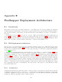
H.1 Introduction . . . . . . . . . . . . . . . . . . . . . . . . . .
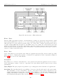
H.2 FAS deployment architecture . . . . . . . . . . . . . . . .
H.2.1 Configuration . . . . . . . . . . . . . . . . . . . . .
H.2.2 Data . . . . . . . . . . . . . . . . . . . . . . . . . .
H.2.3 Live . . . . . . . . . . . . . . . . . . . . . . . . . .
H.2.4 Staging . . . . . . . . . . . . . . . . . . . . . . . .
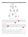
H.2.5 Replication system . . . . . . . . . . . . . . . . . .
H.3 FAS Deployment variabilities . . . . . . . . . . . . . . . .
H.3.1 Data updates variability . . . . . . . . . . . . . . .
H.3.2 Variability . . . . . . . . . . . . . . . . . . . . . . .
H.4 Scenario FP7: Deploying and maintaining an installation
H.4.1 Concrete Example . . . . . . . . . . . . . . . . . .
H.4.2 Concerns and envisioned support by HATS . . . .
III
I
.
.
.
.
.
.
.
.
.
.
.
.
.
.
.
.
.
.
.
.
.
.
.
.
.
.
.
.
.
.
.
.
.
.
.
.
.
.
.
.
.
.
.
.
.
.
.
.
.
.
.
.
.
.
.
.
.
.
.
.
.
.
.
.
.
.
.
.
.
.
.
.
.
.
.
.
.
.
.
.
.
.
.
.
.
.
.
.
.
.
.
.
.
.
.
.
.
.
.
.
.
.
.
.
.
.
.
.
.
.
.
.
.
.
.
.
.
.
.
.
.
.
.
.
.
.
.
.
.
.
.
.
.
.
.
.
.
.
.
.
.
.
.
.
.
.
.
.
.
.
.
.
.
.
.
.
.
.
.
.
.
.
.
.
.
.
.
.
.
.
.
.
.
.
.
.
.
.
.
.
.
.
.
.
.
.
.
.
.
.
.
.
.
.
.
.
.
.
.
.
.
.
.
.
.
.
.
.
.
.
.
.
.
.
.
.
.
.
.
.
.
.
.
.
.
.
.
.
.
.
.
.
.
.
.
.
.
.
.
.
.
.
.
.
.
.
.
.
.
.
.
.
.
.
.
.
.
.
.
.
Models
Notations
I.1 Java Modelling Language . . . . . .
I.1.1 Model Fields . . . . . . . . .
I.1.2 Invariants . . . . . . . . . . .
I.1.3 Pre- and Postconditions . . .
I.1.4 Tool Support . . . . . . . . .
I.2 Communicating Sequential Processes
I.2.1 Syntax . . . . . . . . . . . . .
I.2.2 Semantics . . . . . . . . . . .
I.2.3 Tool Support . . . . . . . . .
136
136
136
136
137
137
138
139
139
139
139
140
140
141
143
.
.
.
.
.
.
.
.
.
.
.
.
.
.
.
.
.
.
.
.
.
.
.
.
.
.
.
.
.
.
.
.
.
.
.
.
.
.
.
.
.
.
.
.
.
.
.
.
.
.
.
.
.
.
.
.
.
.
.
.
.
.
.
.
.
.
.
.
.
.
.
.
.
.
.
.
.
.
.
.
.
.
.
.
.
.
.
.
.
.
.
.
.
.
.
.
.
.
.
.
.
.
.
.
.
.
.
.
.
.
.
.
.
.
.
.
.
.
.
.
.
.
.
.
.
.
.
.
.
.
.
.
.
.
.
.
.
.
.
.
.
.
.
.
.
.
.
.
.
.
.
.
.
.
.
.
.
.
.
.
.
.
.
.
.
.
.
.
.
.
.
.
.
.
.
.
.
.
.
.
.
.
.
.
.
.
.
.
.
.
.
.
.
.
.
.
.
.
.
.
.
.
.
.
.
.
.
.
.
.
.
.
.
.
.
.
.
.
.
.
.
.
.
.
.
.
.
.
.
.
.
.
.
.
.
.
.
.
.
.
.
.
.
.
.
.
.
.
.
.
.
.
.
.
.
.
.
.
.
.
.
.
.
.
.
.
.
.
.
.
.
.
.
.
.
.
.
.
.
J Data types and Functions
K ABS Model of the Trading System
K.1 Model . . . . . . . . . . . . . . . . . . .
K.1.1 Data Types, Type Synonyms and
K.1.2 Interfaces . . . . . . . . . . . . .
K.1.3 Implementations . . . . . . . . .
K.2 Installation . . . . . . . . . . . . . . . .
K.2.1 Interfaces . . . . . . . . . . . . .
K.2.2 Implementations . . . . . . . . .
.
.
.
.
.
.
.
.
.
144
144
144
145
145
145
145
146
146
147
148
. . . . . . . . . . . .
Function Definitions
. . . . . . . . . . . .
. . . . . . . . . . . .
. . . . . . . . . . . .
. . . . . . . . . . . .
. . . . . . . . . . . .
.
.
.
.
.
.
.
.
.
.
.
.
.
.
.
.
.
.
.
.
.
.
.
.
.
.
.
.
.
.
.
.
.
.
.
.
.
.
.
.
.
.
.
.
.
.
.
.
.
.
.
.
.
.
.
.
.
.
.
.
.
.
.
.
.
.
.
.
.
.
.
.
.
.
.
.
.
.
.
.
.
.
.
.
.
.
.
.
.
.
.
.
.
.
.
.
.
.
.
.
.
.
.
.
.
.
.
.
.
.
.
.
.
.
.
.
.
.
.
152
. 152
. 152
. 154
. 156
. 162
. 162
. 162
L ABS Model of the Virtual Office of the Future Component
165
L.1 Data Types and Operations on Data Types . . . . . . . . . . . . . . . . . . . . . . . . . . . . 165
L.2 Interfaces . . . . . . . . . . . . . . . . . . . . . . . . . . . . . . . . . . . . . . . . . . . . . . . 166
L.3 Implementations . . . . . . . . . . . . . . . . . . . . . . . . . . . . . . . . . . . . . . . . . . . 167
6
HATS Deliverable D5.2
Evaluation of Core Framework
M JML Specification of Interval API
M.1 Attribute Type . . . . . . . . . . . . . . . . . .
M.2 ItemVectors . . . . . . . . . . . . . . . . . . . .
M.2.1 Interface ItemVectors . . . . . . . . . .
M.2.2 Implementation Class ItemVectorsImpl
M.3 Interval . . . . . . . . . . . . . . . . . . . . . .
M.3.1 Interface Interval . . . . . . . . . . . .
M.3.2 Abstract Class IntervalBaseImpl . . .
M.3.3 Implementation Class IntInterval . .
.
.
.
.
.
.
.
.
172
. 172
. 172
. 172
. 173
. 175
. 175
. 177
. 179
N ABS Model of Interval API
N.1 Data Types and Type Synonyms . . . . . . . . . . . . . . . . . . . . . . . . . . . . . . . . .
N.2 Functions on ItemVectors . . . . . . . . . . . . . . . . . . . . . . . . . . . . . . . . . . . . . .
N.3 Functions on IntInterval . . . . . . . . . . . . . . . . . . . . . . . . . . . . . . . . . . . . . .
183
. 183
. 183
. 184
O CSP Model of the Replication System
O.1 Preliminaries . . . . . . . . . . . . . . . . . . .
O.1.1 Types . . . . . . . . . . . . . . . . . . .
O.1.2 Connections . . . . . . . . . . . . . . . .
O.1.3 Replication Snapshot . . . . . . . . . . .
O.2 Acceptor Thread SyncServerAcceptorThread
O.3 Coordinator (SyncServerClientCoordinator)
O.4 Connection Thread (ConnectionThread) . . . .
O.5 Synchronisation Server . . . . . . . . . . . . . .
O.6 Synchronisation Client . . . . . . . . . . . . . .
O.7 Replication System and Its Properties . . . . .
.
.
.
.
.
.
.
.
.
.
.
.
.
.
.
.
.
.
.
.
.
.
.
.
.
.
.
.
.
.
.
.
.
.
.
.
.
.
.
.
.
.
.
.
.
.
.
.
.
.
.
.
.
.
.
.
.
.
.
.
.
.
.
.
.
.
.
.
.
.
.
.
.
.
.
.
.
.
.
.
.
.
.
.
.
.
.
.
.
.
.
.
.
.
.
.
.
.
.
.
.
.
.
.
.
.
.
.
.
.
.
.
.
.
.
.
.
.
.
.
.
.
.
.
.
.
.
.
.
.
.
.
.
.
.
.
.
.
.
.
.
.
.
.
.
.
.
.
.
.
.
.
.
.
.
.
.
.
.
.
.
.
.
.
.
.
.
.
.
.
.
.
.
.
.
.
.
.
.
.
.
.
.
.
.
.
.
.
.
.
.
.
.
.
.
.
.
.
.
.
.
.
.
.
.
.
.
.
.
.
.
.
.
.
.
.
.
.
.
.
.
.
.
.
.
.
.
.
.
.
.
.
.
.
.
.
.
.
.
.
.
.
.
.
.
.
.
.
.
.
.
.
.
.
.
.
.
.
.
.
.
.
.
.
.
.
.
.
.
.
.
.
.
.
.
.
.
.
.
.
.
.
.
.
.
.
.
.
.
.
.
.
.
.
.
.
.
.
.
.
.
.
.
.
.
.
.
.
.
.
.
.
.
.
.
.
.
.
.
.
.
.
.
.
.
.
.
.
.
.
.
.
187
187
187
187
188
188
189
191
192
193
196
P ABS Model of the Replication System
P.1 Data Types, Type Synonyms and Function Definitions . . . . . . . . .
P.2 Interface Definition . . . . . . . . . . . . . . . . . . . . . . . . . . . . .
P.2.1 Database . . . . . . . . . . . . . . . . . . . . . . . . . . . . . .
P.2.2 Node, SyncServer and SyncClient . . . . . . . . . . . . . . . . .
P.2.3 Acceptor Thread, Replication Coordinator and Replication Job
P.3 Database . . . . . . . . . . . . . . . . . . . . . . . . . . . . . . . . . .
P.4 Synchronisation Server . . . . . . . . . . . . . . . . . . . . . . . . . . .
P.5 Coordinator . . . . . . . . . . . . . . . . . . . . . . . . . . . . . . . . .
P.6 Acceptor Thread . . . . . . . . . . . . . . . . . . . . . . . . . . . . . .
P.7 Connection Thread . . . . . . . . . . . . . . . . . . . . . . . . . . . . .
P.8 Synchronisation Client . . . . . . . . . . . . . . . . . . . . . . . . . . .
P.9 Client Job . . . . . . . . . . . . . . . . . . . . . . . . . . . . . . . . . .
P.10 Initialisation . . . . . . . . . . . . . . . . . . . . . . . . . . . . . . . .
.
.
.
.
.
.
.
.
.
.
.
.
.
.
.
.
.
.
.
.
.
.
.
.
.
.
.
.
.
.
.
.
.
.
.
.
.
.
.
.
.
.
.
.
.
.
.
.
.
.
.
.
.
.
.
.
.
.
.
.
.
.
.
.
.
.
.
.
.
.
.
.
.
.
.
.
.
.
.
.
.
.
.
.
.
.
.
.
.
.
.
.
.
.
.
.
.
.
.
.
.
.
.
.
.
.
.
.
.
.
.
.
.
.
.
.
.
.
.
.
.
.
.
.
.
.
.
.
.
.
.
.
.
.
.
.
.
.
.
.
.
.
.
.
.
.
.
.
.
.
.
.
.
.
.
.
.
.
.
.
.
.
.
.
.
.
.
.
.
197
197
198
198
198
199
200
201
203
205
206
208
209
211
7
.
.
.
.
.
.
.
.
.
.
.
.
.
.
.
.
.
.
.
.
.
.
.
.
.
.
.
.
.
.
.
.
.
.
.
.
.
.
.
.
.
.
.
.
.
.
.
.
.
.
.
.
.
.
.
.
.
.
.
.
.
.
.
.
.
.
.
.
.
.
.
.
.
.
.
.
.
.
.
.
.
.
.
.
.
.
.
.
.
.
.
.
.
.
.
.
.
.
.
.
.
.
.
.
.
.
.
.
.
.
.
.
.
.
.
.
.
.
.
.
Part I
Evaluation
8
Chapter 1
Introduction
The goal of Task 5.2 is to test the expressive power of the core ABS language and HATS methodology in the
case studies. The activities include extensive requirement analysis of the scenarios defined in Task 5.1 [28].
This task closely cooperated with the activities of Task 1.1, so that the requirement analysis drives the
design of the innovative software development method developed in Task 1.1. It is the basis for verification
of Milestone M1 “core language and methodology”.
Task 5.2 is partitioned into two activities: requirement analysis for the other relevant work tasks in the
project and the evaluation of the core framework (validation of M1). This deliverable report presents the
results of these two activities.
1.1
Requirement Analysis
In Task 5.1 [28] we identified a set of high level concerns for each candidate case studies of the project.
In this task, we refined these concerns into concrete requirements with concrete test cases and evaluation
criteria. These test cases can be used directly to test technical deliverable results from work tasks. The
evaluation criteria can then be used to measure whether deliverable results satisfy the intended requirements.
Specifically, we conducted a series of interactive requirement analysis sessions with members of technical
work tasks. We present the results of these requirement analysis sessions in Chapter 2.
1.2
Evaluation
We test and evaluate the ABS language and the HATS methodology by considering three case studies
introduced in D5.1 [28]. For each case study, we present the requirements of some of the components and
construct ABS models to describe these components’ behaviours. For the Trading System case study, we
consider the cash desk component. For the Virtual office of the future case study, we consider the Node
management component. For the Fredhopper case study we consider two components in the Fredhopper
Access Server (FAS): Fredhopper Interval API and Replication System. The Fredhopper Interval API is an
in-house API for expressing mathematical intervals, and the Replication System implements a concurrent
protocol for maintaining data consistency in a typical FAS deployment. We now give a brief overview of
each case study.
1.2.1
Trading System Case Study
The Trading System is an academic case study of medium size. It is a typical example for a distributed
component-based information system. It includes the processes at a single cash desk like scanning products
using a bar code scanner or paying by credit card or cash as well as administrative tasks like ordering of
running out products or generating reports. The Trading System example was also used in the CoCoME
9
HATS Deliverable D5.2
Evaluation of Core Framework
modelling contest [27, 11], which is based on an idea of Larman [21]. A detailed description is given in
D5.1 [28, Chapter 3].
As the Trading System case study is of a medium size, the ultimate goal for HATS is to provide an ABS
model for the whole system. In this work task, we use the case study to evaluate the expressiveness of the
Core ABS language. This is done by taking the core functionality of the Trading System and model it by
using the ABS language using the ABS tools at the current state of completion. The core functionality of the
Trading System is covered by the Cash Desk components as well as the Cash Desk Line component, which
manages a set of Cash Desks. With these components the basic use cases of the CoCoME requirements [27]
are already completely covered. To be able to simulate these components without providing a model for
the whole system, we take the approach to make the dependencies of these components explicit by using
interfaces and by providing a model for the environment of these components in ABS. This approach proved
to be successful and allowed us to test and simulate the core components by simulating the basic use cases
of the CoCoME in the Maude runtime system.
1.2.2
Virtual Office of the Future Case Study
The Virtual Office of the Future (VOF) system case study, as described in D5.1 [28, Chapter 4], consists
of several components and uses external technologies for communication and user interaction. Furthermore
configuration artifacts like deployment descriptors are involved that are crucial to the system’s functionality.
To conduct the evaluation we started with the documentation of the VOF System, as it was done in [28,
Chapter 4]. Additionally the documentation of the existing implementation [35] was taken into account.
After identifying a component that was large enough to test the expressive power of ABS but also small
enough to be handled in this experiment the specification was done in a more formal way. To do so the
KobrA [5] approach was used. With the help of this semi-formal method ABS interface specifications could
be defined. Finally, the implementation was done according to the method specification.
1.2.3
Fredhopper Case Study
The Fredhopper case study is an industrial case study. In this case study we consider the Fredhopper Access
Server (FAS). FAS is a component-based, service-oriented and server-based software system, which provides
search and merchandising IT services to e-Commerce companies such as large catalogue traders, travel
booking, classified advertising etc. A more detailed description of FAS is provided in D5.1 [28, Chapter 5].
In this work task we have chosen to study the Fredhopper Interval API and the Replication System from
FAS. They are different in size, application area and in the nature of their behaviours. Specifically, we have
selected the Interval API because it represents a single-threaded library providing fundamental services via
its interface to other components of the FAS product. We have selected the replication system because
it represents a multi-threaded application that supports multiple jobs which transport data through the
distributed setup of a typical FAS deployment.
For each component we study its current implementation, understand their informal requirements and
derive or mine two layers of models. The first layer are high-level formal specifications of the concrete
implementation using existing formalisms, and the second layer is an executable ABS model. We report on
this case study in Chapter 5.
1.2.4
Methodological and Language Evaluation
In addition, in all three case study chapters we indicate how the specific modelling approach fits naturally
into parts of the HATS methodology. We provide an evaluation of the (core subset of) ABS language and
its associated tool support with respect to the requirements identified in D5.1 [28].
10
HATS Deliverable D5.2
1.3
Evaluation of Core Framework
Evaluation Criteria
In this section we present the evaluation criteria for the validation of the core ABS language and the HATS
methodology. These criteria are considered by individual case studies. We revisit them in our conclusion in
Chapter 6.
1.3.1
Core ABS Language
We evaluate the core ABS language with respect to the following types of criteria.
Requirement descriptions: We evaluate the core ABS language with respect to concrete requirements
harvested during Task 5.2. In Task 5.1 we identified high level concerns that the HATS framework
should address.1 These high level concerns are subsequently refined during requirement analysis sessions in Task 5.2 to generate concrete test cases and evaluation criteria. As a result, we elicited
Requirements TS-R-1.1-1, FP-R-1.1-1 and FP-R-1.1-2 for the validation of the core ABS language.
Their description can be found in Section 2.2.1 of Chapter 2. Specifically, the core ABS language must
satisfy the following criteria:
Specification of sequential programs We evaluate the core ABS language with respect to this
criterion by conducting a modelling exercise on components extracted from candidate case studies.
Specification of concurrent programs We evaluate the core ABS language with respect to this
criterion by conducting a modelling exercise on components extracted from candidate case studies.
Abstraction: We evaluate the core ABS language with respect to the type of abstraction the language
provides. Abstraction is important specifically for an abstract modelling language as it encourages
scalable analysis and formal reasoning.
Expressivity: We evaluate the core ABS language with respect to the practical language expressiveness.
In particular we investigate from the user’s perspective how readily and concisely the core language
allows users to express program structures and behaviour.
1.3.2
HATS Methodology
The HATS methodology is presented in Deliverable 1.1b (D1.1b) [23] and has subsequently been published
in the proceedings of FMSPLE [9]. We evaluate the HATS methodology from experimental and requirement
perspectives.
Experiment
At this stage of the project it is not possible to consider the complete HATS methodology. Instead in our
validation process, we study partially a few steps in the methodology and consider how tasks (requirement
elicitation, analysis, design etc.) can fit into these steps. Since each case study is vastly different in scale,
application area and contexts, the modelling approach for each case study will be different. As a result
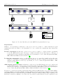
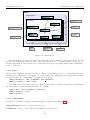
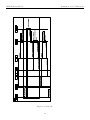
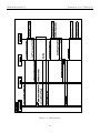
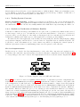
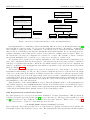
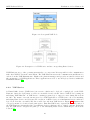
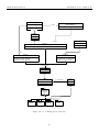
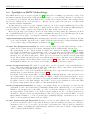
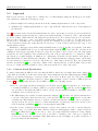
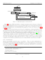
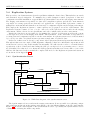
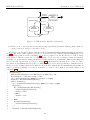
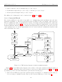
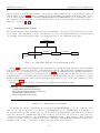
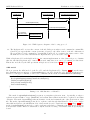
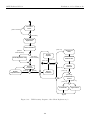
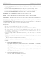
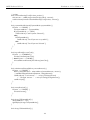
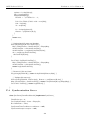
each case study considers some of the steps in the HATS methodology. Figure 1.1 shows the product line
lifecycle in the HATS development methodology and highlights the phases where HATS contributes to it.
Specifically, each case study considers some or all of the following steps in the methodology: Product
Line Requirement Analysis, Reference Architecture, Generic Component Design, Generic Component Realisation, Generic Component Validation, Application Engineering Planning and Product Construction and
Integration. Details of these steps can be found in D1.1b [23].
1
The HATS framework consists of the HATS methodology and the ABS language with associated analysis techniques and
tool support.
11
HATS Deliverable D5.2
Evaluation of Core Framework
Application Engineering (AE) Process
Reference
Architecture
Instantiation
Product
Construction and
Integration
System
Validation
System
Delivery
Maintenance and
Evolution
Feedback
Application Engineering Product Line Model
Instantiation and
Planning
Validation
Product
Line
Artifact
Base
Evolution
Process
Continuous
Improvement
Process
Family Engineering (FE) Process
Product Line
Planning
and Scoping
Product Line
Requirement
Analysis
Reference Architecture
Design
Generic Component
Design
Generic Component
Realization
Generic Component
Validation
Legend
Interaction
Dependency
Variability
Management
Process
Input/Output
Phase
with HATS Contribution
Process
Figure 1.1: Product Line Lifecycle in the HATS Development Methodology
Requirements
Similar to our experiment, at this stage of the project it is not possible to consider all methodological
requirements elicited in Task 5.1. In particular we do not consider the requirements that demand the
following:
Iterative experiment At this stage of the project, it is not possible to conduct iterative experiments
to test the HATS methodology. We hope to evaluate the methodology with respect to this type of
requirements at a later validation task (Task 5.4). Specifically we do not consider Requirements MR8,
MR9, MR14 and MR23 described in D5.1 [28].
Product line construction As the core ABS language is yet to be extended to handle product line variability, he consideration of requirements, which demand product line construction is relegated to later
validation tasks (Tasks 5.3 and 5.4). Specifically, we do not consider Requirements MR1 to MR6
described in D5.1 [28].
ABS language specific features At this stage of the project, the ABS language is not yet complete and
not all techniques and tool support have been delivered. We relegate the evaluation of the methodology
with respect to this type of requirements at later validation tasks (Tasks 5.3 and 5.4). Specifically we
do not consider Requirements MR15, MR16, MR20 and MR21 described in D5.1 [28].
We therefore consider the following requirements when testing the HATS methodology: tailorability (MR7),
scalability (MR10), learnability (MR11), usability (MR12), reducing manual effort (MR13), protocol analysis (MR17), integrated environment support (MR18), existing modelling techniques support (MR19), and
middleware abstraction (MR22). Note that each case study is vastly different in scale, application area
12
HATS Deliverable D5.2
Evaluation of Core Framework
and context, and each case study considers some or all of these requirements. For example, MR17 concerns
protocol analysis and will currently be only considered in the industrial Fredhopper case study in Chapter 5.
Description of the methodological requirements can be found in Section A.1 in Appendix A.
When consider methodological requirements during evaluation, we also investigate how the core ABS
language and associated tool support help satisfying these requirements. Regarding tool support currently
there is a Eclipse plug-in that allows users to edit ABS scripts using the Eclipse IDE.2 The plug-in provides
syntax highlighting, basic navigation of ABS scripts based on data type, function, interface and class definitions. In addition, syntax highlighting is provided for Emacs editing.3 There is also a stand alone type
checker. ABS models specified as scripts may be simulated using the Maude engine.4 A compiler is provided
that translate ABS scripts into Maude scripts for simulation. Note that Requirements MR11, MR12, MR13
and MR18 are the basic requirements that guided the design of the core ABS language [1, Section 2.3].
1.4
Scope of Case Studies
For purpose of testing the core ABS language, we do not consider the variability and the evolvability
of systems in this deliverable. Specifically, in each case study we construct ABS models to describe the
behaviour of components of an existing distributed system. In the case of the Trading System and VOF
case studies, this system is a set of static informal requirements that describes the system’s structure and
behaviour. And in the case of the Fredhopper case study, this system is a single snapshot of an existing
Java implementation that is currently in use and in development. In addition, in this deliverable, we do not
consider iterative development approaches in these case studies. Both of these aspects will be considered in
Tasks 5.3 and 5.4. This corresponds to our choice of methodological requirements in Section 1.3.2.
For the purpose of references, in Appendix J we provide built-in data type and function definitions of
ABS that we use in all three case studies.
1.5
Structure of Deliverable
The structure for this deliverable is as follows: Chapter 2 presents the result of further requirement analyses
conducted in Task 5.2. In Chapters 3, 4 and 5, we present the evaluation of the core ABS language by
modelling parts of the Trading System, VOF and Fredhopper case studies respectively. We conclude this
deliverable in Chapter 6.
2
http://www.eclipse.org
http://www.gnu.org/software/emacs/
4
http://maude.cs.uiuc.edu/
3
13
Chapter 2
Requirement Analysis
2.1
Introduction
Deliverable 5.1 (D5.1) [28] presents methodological requirements that the HATS framework should meet.
D5.1 also presents high level concerns derived from candidate case studies of the HATS project. In Task 5.2,
we refined the high level concerns with concrete examples and evaluation criteria. This is so that they can
be directly applicable to work tasks.
2.1.1
Analysis
We refined high level concerns documented in D5.1 into concrete requirements via a refinement process
conducted the form of interactive requirement analysis sessions. While high level concerns are case study
oriented and each concern may apply to deliverables of multiple work tasks in the project, a (concrete)
requirement, on the other hand, is a concrete description of a particular aspect a work task should meet.
Specifically a requirement has the following elements.
• Unique identification of the requirement.
• Reference one or more case study scenarios where the high level concerns were identified.
• Reference to one or more high level concerns from which this requirement refines.
• A textual description of the requirement.
• Concrete test cases that are used to test whether the corresponding work task meets this requirement.
• A list of evaluation criteria that are used to interpret the results of test cases.
Requirements of a work task are defined during a series of interactive requirement analysis sessions. Each
session is attended by members of that work task as well as members of Task 5.2. The aim of each session
is to generate concrete requirements for the work task and in doing so we strive to answer the following
questions.
• Are requirement descriptions complete? That is, do they specify all the requirements for this task?
• Is each requirement cohesive? That is, does each requirement specify one functionality/quality provided by the result of this task)?
• Does everyone in the work task understand each requirement for this task? This ensures clarity and
makes explicit the scope control and evaluation criteria of the work task.
• Does each requirement description contain sufficient information and is not ambiguous?
14
HATS Deliverable D5.2
Evaluation of Core Framework
• Does everyone agree on the feasibility of the requirement?
• Is there a priority of requirements? That is, are some requirements mandatory or optional?
• Do all requirement descriptions adhere to the terminology used in the task? This is to ensure requirement descriptions do not get “lost in translation”.
2.1.2
Result
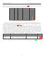
Task 5.2 has been scheduled between project month 6 (PM6) and project month 17 (PM17). Some of the
work tasks in the project will not begin until after PM17, while other work tasks are more concerned with
theoretical foundations that will subsequently be applied in later work tasks to develop techniques and tool
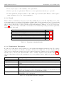
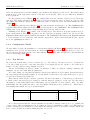
support. As a result we have conducted detailed requirement analysis for Tasks 1.1, 1.2, 2.1, 2.2, 3.1 and 4.2.
Table 2.1 relates each of these work tasks to its relevant section in this chapter that presents the requirement
analysis result of the task.
Task
T1.1:
T1.2:
T2.1:
T2.2:
T3.1:
T4.2:
Number and Name
Core ABS Language
Feature Modelling, Platform Models, and Configuration
A Configurable Deployment Architecture
Feature Integration
Evolvable Systems: Modelling and Specification
Resource Guarantees
Results
Section 2.2.1
Section 2.2.2
Section 2.2.3
Section 2.2.4
Section 2.2.5
Section 2.2.6
Table 2.1: Requirement Analysis Results
2.1.3
Requirement Description
For the rest of this chapter, the presentation of each requirement analysis result is threefold: We begin by
giving a brief description of work task contribution and associated high level concerns. We then present
each concrete requirement description in a table format following the template described in Table 2.2. We
will also refer to concrete test cases that will be used to evaluate outputs of the work task. Table 2.14 at
the end of this chapter relates each requirement to its corresponding scenarios, high level concerns and work
tasks.
Name
Requirement
Scenarios
High Level Concerns
Description
Test Cases
Accompanying Material
Evaluation Criteria
Description
Identifier and Name of the requirement
Reference to relevant scenarios in D5.1
Reference to relevant high level concerns in D5.1 from which this requirement
refines.
Textual description of the requirement
Textual description of the format and nature of test cases.
Description of any materials necessary to conduct evaluation of work task’s contribution with respect to this requirement. For example, accompanying materials
may be the description of the concern and the scenario.
Criteria against which relevant work tasks would be benchmarked to measure the
satisfiability of the requirement.
Table 2.2: Requirement Description Template
15
HATS Deliverable D5.2
Evaluation of Core Framework
Identification Each requirement has a unique identification of the form CS-R-TN-I. Here CS refers the
case study where the high level concerns are refined by the requirement. CS takes is one of TS, VF and FR
representing Trading system, VOF and Fredhopper case studies respectively. TN refers to the work task of
which this requirement is identified. I is a non zero positive integer value, identifies the requirement to be
the Ith requirement refined from concerns of a particular case study for a particular work task. For example
Requirement TS-R-1.1-1 is the first concrete requirement of Task 1.1 refined from the Trading System case
study.
2.2
2.2.1
Requirement Analysis Results
Task 1.1: Core ABS Language
The contribution of Task 1.1 is twofold: The core ABS language and the HATS methodology. Since the
requirements of HATS methodology are the methodological requirements described in D5.1 [28, Chapter 2],
we therefore focus on the requirement analysis of the core ABS language in this section. In D5.1, there are
three high level concerns specific to Task 1.1: TS-C6 [28, Page 23], FP-C1 [28, Page 43] and FP-C11 [28,
Pages 50–51].
Name
Requirement
Scenarios
High Level Concerns
Description
Test Cases
Accompanying Material
Evaluation Criteria
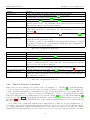
Detail
TS-R-1.1-1: Specification of the Cash Desk component
Scenario TS2 [28, Section 3.2.2]
Concern TS-C6 [28, Page 23]
The core ABS language should provide language constructs to model the basic
Trading System as described by the CoCoME requirements.
Informal requirements of the Trading System from the CoCoME documentation [27].
Textual description of Concern TS-C6 [28, Page 23].
1. It must be possible to define the ABS model of the Cash Desk component.
2. It must be possible to simulate the produced ABS model.
Table 2.3: Requirement TS-R-1.1-1
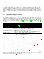
Concern TS-C6 is identified from the Trading System case study. TS-C6 is concerned with the general
modelling of one variation of the Cash Desk component [27]. Table 2.3 shows Requirement TS-R-1.1-1 as a
result of analysing high level Concern TS-C6. Using the original CoCoME requirements of the Cash Desk
component, we perform an evaluation of the core ABS language. The result of this is presented in Chapter 3
of this deliverable.
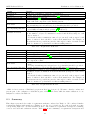
Concerns FP-C1 and FP-C11 are identified from the Fredhopper case study. FP-C1 is concerned with
the specification of sequential programs and FP-C11 is concerned with the specification of concurrent programs. As a result of the requirement analysis on Task 1.1, we identified the specification of the concrete
requirements for evaluating the core ABS language that will be delivered by Task 1.1. Table 2.4 shows
Requirement FP-R-1.1-1 as the result of analysing high level Concern FP-C1. Table 2.5 show Requirement
FP-R-1.1-2 as the result of analysing high level Concern FP-C11.
We have identified two suitable components of FAS as test cases. For Concern FP-C1, we considered
the Fredhopper Interval API as the candidate test case. For Concern FP-C2, we considered the Replication
System as the candidate test case. Subsequently we conducted an evaluation of the core ABS language using
these test cases. The modelling and evaluation can be found in Chapter 5 of this deliverable.
While no concern specific to Task 1.1 has been elicited from the Virtual office of the future (VOF)
case study, we conducted an evaluation of the core ABS language by studying and modelling the Node
management component of the VOF platform. The modelling of this component and the corresponding
evaluation can be found in Chapter 4 of this deliverable.
16
HATS Deliverable D5.2
Name
Requirement
Scenarios
High Level Concerns
Description
Test Cases
Accompanying Material
Evaluation Criteria
Evaluation of Core Framework
Detail
FP-R-1.1-1: Specification of Sequential Programs
Scenario FP1 [28, Section 5.2.1]
Concern FP-C1 [28, Page 43]
The core ABS language should provide language constructs to: 1. model units
of object oriented code, and 2. specify precisely the (behavioural) correctness of
units.
1. A stand alone Java source file documenting a class definition with text-based
specification of method-level contracts.
2. For any external imports, mocks should be provided with text-based specification of behavioural assumptions.
Textual description of Concern FP-C1 [28, Page 43]
1. It should be possible to define a (core) ABS model(s) of the class definition,
and where certain object oriented features are directly not supported, such as
class inheritances and global static fields, alternative representation in the core
ABS language should be used.
2. It should provide a formal specification of the methods and classes.
3. It should be possible to simulate the produced ABS model(s) to validate the
methods’ behaviour against their contracts.
Table 2.4: Requirement FP-R-1.1-1
Name
Requirement
Scenarios
High Level Concerns
Description
Test Cases
Accompanying Material
Evaluation Criteria
Detail
FP-R-1.1-2: Specification of Concurrent Programs
Scenario FP4 [28, Section 5.2.4]
Concern FP-C11 [28, Pages 50–51]
The core ABS language should provide language constructs to: 1. model a concurrent (multi-threaded) unit of object oriented code, and 2. specify precisely
the (concurrent behavioural) correctness of units.
1. A stand alone Java source file documenting a class definition with text-based
specification of method’s behaviours.
2. For any external imports, mocks should be provided with text-based specification of behavioural assumptions.
Textual description of Concern FP-C11 [28, Pages 50–51]
1. It should be possible to define a (core) ABS model(s) of the class definition,
and where certain object oriented features are directly not supported, such as
class inheritances and global static fields, alternative representation in the core
ABS language should be used.
2. It should be possible to simulate the produced ABS model(s) to validate the
methods’ behaviour against their contracts.
Table 2.5: Requirement FP-R-1.1-2
2.2.2
Task 1.2: Feature Modelling, Platform Models, and Configuration
In Task 1.2, the language constructs for expressing feature and platform models for ABS will be developed.
This development of language mechanisms goes hand in hand with the concepts of modelling variability
and evolvability. The relevant concerns identified from D5.1 are TS-C2 [28, Page 23] and TS-C6 [28, Page
22] from the Trading System case study, and VF-C6 [28, Page 33] and VF-C14 [28, Page 34] from the
VOF case study. The result of the requirement analysis session is a set of the textual use case descriptions
for variability modelling. These use cases will be used as benchmarks to evaluate the feature modelling
17
HATS Deliverable D5.2
Evaluation of Core Framework
capability of the ABS language delivered by this task.
Name
Requirement
Scenarios
High Level Concerns
Description
Test Cases
Accompanying Material
Evaluation Criteria
Detail
TS-R-1.2-1: Feature Modelling of the Coupon Handling Feature
Scenarios TS1: Coupon Handling Feature [28, Section 3.2.1]
Scenarios TS5: Loyalty System [28, Section 3.2.5]
Concerns TS-C2 [28, Page 23] and TS-C12 [28, Page 26]
The coupon handling feature described in Scenario TS1 should be modelled as a
single feature. It should then be possible to create variants of the Trading System
with or without the coupon handling feature. In addition, the loyalty system
feature, described in Scenario TS5, should be modelled on top of the coupon
handling feature of Scenario TS1. The important point of this requirement is
that the ABS language should support feature composition.
Use cases of the coupon handling and the loyalty system features, describing
variability focusing on variations, constraints, dependency, assumption, hardware
variation, and deployment variation. The use case descriptions can be found in
Appendix B.
Textual description of Concerns TS-C2 [28, Page 23] and TS-C12 [28, Page 26]
1. It must be possible to apply the feature modelling capability provided by the
ABS language to model the variations, constraints, dependency of the features
described in the textual description requirements.
2. Consistency between these features can be formalised and verified under the
theory of feature refinement developed in Task 1.2.
Table 2.6: Requirement TS-R-1.2-1
TS-C2 is concerned with the modelling of the coupon handling feature as a variability, while TS-C6 is
concerned with the modelling of different variations of the cash desk component. Note that as a result of
this further requirement analysis, we extend TS-C2 to include the modelling of the loyalty system feature.
The loyalty system feature is described in Scenario TS5 [28, Section 3.2.5] and the modelling of this feature
is identified by Concern TS-C12 [28, Page 26]. Table 2.6 shows Requirement TS-R-1.2-1 as the result of
analysing high level Concerns TS-C2 and TS-C12, and Table 2.3 shows Requirement TS-R-1.2-2 as the result
of analysing high level Concern TS-C6. Corresponding requirement test cases can be found in Appendix B
and C respectively.
VF-C6 [28, Page 33] is concerned with the modelling of platform and hardware variability of the VOF
framework, while VF-C14 [28, Page 34] is concerned with with the modelling of new functionalities in the
VOF framework as variability of the framework. Tables 2.8 shows Requirement VF-R-1.2-1 as the result of
analysing high level Concern VF-C6 and Table 2.9 shows Requirement VF-R-1.2-2 as the result of analysing
high level Concern VF-C14. Corresponding requirement test cases can be found in Appendices D and E
respectively.
Note that as part of results of the further requirement analysis, we have identified that the requirement
description from Concerns VF-C6 and VF-C14 and their associated test cases may also be used to test and
evaluate the expressiveness of the configuration deployment model, which is a deliverable result of Task 2.1.
The requirement analysis of Task 2.1 is described in Section 2.2.3.
2.2.3
Task 2.1: A Configurable Deployment Architecture
Task 2.1 develops a configurable deployment model that can be integrated into the ABS language for
specifying platform variability about concurrency, distribution and fault tolerance. At the initial requirement
analysis session, we have concluded that it was necessary to perform the following two extensions to the
scenarios and concerns described in D5.1.
18
HATS Deliverable D5.2
Name
Requirement
Scenarios
High Level Concerns
Description
Test Cases
Accompanying Material
Evaluation Criteria
Evaluation of Core Framework
Detail
TS-R-1.2-2: Variability Modelling of Different Cash Desk Variants
Scenario TS2: Cash Desk Variability [28, Section 3.2.2]
Concern TS-C6 [28, Page 23]
The feature modelling capability provided by the ABS language should allow
one to model the different cash desk variants. For example, different payments
options like cash payment and electronic payment may be modelled [28, Page 20]
Use cases about cash desk variability focusing on variations, constraints, dependency, assumption, hardware variation, and deployment variation. Use case
descriptions can be found in Appendix C.
Textual description of Concern TS-C6 [28, Page 23]
1. It is possible to apply the feature modelling capability provided by the ABS
language to model the variations, constraints, dependency of the features described in the textual description requirements.
2. It should be possible to verify consistency between different views of the feature
model.
Table 2.7: Requirement TS-R-1.2-2
Name
Requirement
Scenarios
High Level Concerns
Description
Test Cases
Accompanying Material
Evaluation Criteria
Detail
VF-R-1.2-1: Platform and Hardware Modelling
Scenario VF2: Add a new device type to the VOF infrastructure [28, Section
4.3.2]
Concern VF-C6 [28, Page 33]
Mobile device platforms have specifics that need to be considered when developing applications based on them, for instance, iPhone 3GS does not support
multi-tasking for all applications. Hence, the ABS language needs to provide
the capability to modelling mobile device platforms at an appropriate level of
abstraction.
Use case description of adding various device types to the VOF infrastructure,
describing their variabilities in terms of constraints, dependency, assumption,
hardware variation, and deployment variation. Use case descriptions can be found
in Appendix D.
Textual description of Concern VF-C6 [28, Page 33]
It should be possible for the HATS framework to provide the necessary language
constructs (in ABS), modelling techniques and tool supports to specify variability
of the platform and hardware as described in the textual description requirements.
Table 2.8: Requirement VF-R-1.2-1
First, we extend Concerns VF-C6 and VF-C14 such that concrete test cases specified for Requirements
VF-R-1.2-1 and VF-R-1.2-2 can also be used for evaluation of the deployment model delivered by this
task. Concrete test cases of Requirements VF-R-1.2-1 and VF-R-1.2-2 can be found in Appendix D and E
respectively.
Second, we extend the Fredhopper case study with Scenario FP7 focusing on the deployment and the
maintenance of a physical FAS installation. Subsequently we identified three high level Concerns FP-C22,
FP-C23 and FP-C24 on the analysis of service level agreement, and the verification of data consistency and
fault tolerance in a FAS installation. A presentation of the FAS deployment architecture and Scenario FP7
can be found in Appendix H.
Following from these extensions, we plan to conduct a second requirement analysis session with Task 2.1.
The aim of this second session is twofold. To analyse Concerns FP-C22 and FP-C23 identified by Scenario
19
HATS Deliverable D5.2
Name
Requirement
Scenarios
High Level Concerns
Description
Test Cases
Accompanying Material
Evaluation Criteria
Evaluation of Core Framework
Detail
VF-R-1.2-2: Platform and Hardware Modelling
Scenario VF5: Integration of new functionality in the VOF P2P Platform [28,
Section 4.3.5]
Concern VF-C14 [28, Page 34]
Secure communication between nodes in the VOF infrastructure shall be modelled
as an optional feature. Furthermore, it should be configurable at run-time, for
instance, the level of encryption should be configurable. These optional feature
and configuration possibilities must be modelled.
Use case description of secure communication in the VOF infrastructure focusing
on variability information such as variations (attributes/cardinality), constraints,
dependency, assumption, hardware variation, and deployment variation. Use case
descriptions can be found in Appendix E.
Textual description of Concern VF-C14 [28, Page 34]
It should be possible for the HATS framework to provide the necessary language
constructs (in ABS), modelling techniques and tool supports to specify variability
of the platform and hardware as described in the textual description requirements.
Table 2.9: Requirement VF-R-1.2-2
FP7 of the Fredhopper case study and to refine Concern VF-C19 of VOF case study. We aim to conduct
this activity in Task 5.3.
2.2.4
Task 2.2: Feature Integration
Task 2.2 investigates and develops behavioural models of features, feature interaction and feature integration
in the ABS language by developing language constructs for manipulating and combining components, based
on the variation points. The relevant concerns identified from D5.1 are TS-C2 [28, Page 23] and TS-C6 [28,
Page 22] from the Trading System case study. Similar to Task 1.2, the result of the requirement analysis
session are textual use case descriptions for modelling feature behaviours. These use cases will be used as
benchmarks to evaluate the analysis technique developed in this task.
TS-C2 is concerned with the modelling of the coupon handling feature as a variability, while TS-C6 is
concerned with the modelling of different variations of the cash desk component. Note that, similar to Task
1.2, as a result of this further requirement analysis, we extend TS-C2 to include the modelling of the loyalty
system feature. The loyalty system feature is described in Scenario TS5 [28, Section 3.2.5] and the modelling
of this feature is identified by Concern TS-C12 [28, Page 26]. Tables 2.10 shows Requirement TS-R-1.2-1
as the result of analysing high level Concerns TS-C2 and TS-C12, and Table 2.11 shows Requirement TSR-1.2-2 as the result of analysing high level Concern TS-C6. Corresponding requirement test cases can be
found in Appendices F and G respectively.
2.2.5
Task 3.1: Evolvable Systems: Modelling and Specification
The aim of Task 3.1 is to analyse and model fundamental aspects of system and component evolution, to
formally pin down and compare the concepts, construct scenarios, and to build formal execution models
that can be subjected to evaluation, theoretical examination, comparison, and simulation.The results of this
work task are the theoretical foundation of specifying and modelling evolvable system. These results are
to be applied to extend the ABS language with constructs to model evolvability, as part of the deliverable
result of Task 1.2. As a result while there are high level concerns identified in D5.1, we do not conduct
evaluation directly to results of Task 3.1. Instead, we evaluate results of Task 3.1 indirectly by conducting
detailed case studies using the ABS language. This activity will be the main deliverable result of Task 5.3,
which begins in project month 18 (PM18).
20
HATS Deliverable D5.2
Name
Requirement
Scenarios
High Level Concerns
Description
Test Cases
Accompanying Material
Evaluation Criteria
Evaluation of Core Framework
Detail
TS-R-2.2-1: Feature Modelling of the Coupon Handling Feature
Scenarios TS1: Coupon Handling Feature [28, Section 3.2.1]
Scenarios TS5: Loyalty System [28, Section 3.2.5]
Concerns TS-C2 [28, Page 23] and TS-C12 [28, Page 26]
It should be possible to model and formally establish properties about the behaviours defined by the coupon handling feature and the loyalty system using the
ABS language and associated formal techniques.
Use cases about coupon handling feature and loyalty system focusing on the
behavioural description of each variation. Use case descriptions can be found in
Appendix F.
Textual description of the Concerns TS-C2 [28, Page 23] and TS-C12 [28, Page
26]
1. It should be possible for the HATS feature integration technique to model the
behaviour described in the use cases.
2 It should be possible to use the HATS feature integration technique to formalise
the textual description and correspondingly formally show (via testing) that the
failure isolation property is satisfied.
Table 2.10: Requirement TS-R-2.2-1
Name
Requirement
Scenarios
High Level Concerns
Description
Test Cases
Accompanying Material
Evaluation Criteria
Detail
TS-R-2.2-2: Variability Modelling of Different Cash Desk Variants
Scenario TS2: Cash Desk Variability [28, Section 3.2.2]
Concern TS-C6 [28, Page 23]
It should be possible to model and formally establish properties about the behaviours of different variations of the cash desk component using the ABS language and associated formal techniques.
Use cases about cash desk variability focusing on the behavioural description of
each variation. Use case descriptions can be found in Appendix G.
Textual description of Concern TS-C6 [28, Page 23]
It should be possible for the HATS feature integration technique to formalise the
behaviour described in the use cases, allowing one to make a formal analysis of
the behaviours of features.
Table 2.11: Requirement TS-R-2.2-2
2.2.6
Task 4.2: Resource Guarantees
Task 4.2 is concerned with the development of the cost analysis tool – COSTA [4] to statically inferring
closed-form upper bounds on the resource usage of program, parametric on some cost model for verifying the
bounds. Currently, COSTA has been implemented to support sequential Java bytecode programs. The idea
is to extend this technique to support concurrency such that the tool can become applicable in the HATS
framework. The task’s corresponding high level Concerns are TS-C4 [28, Page 23], FP-C20 and FP-C21 [28,
Pages 55–56]. Table 2.12 shows Requirement TS-R-4.2-1 as the result of analysing high level Concern TSC4. Table 2.13 shows Requirement FP-R-4.2-1 as the result of analysing high level Concerns FP-C20 and
FP-C21.
As a result of the requirement analysis session with members of Task 4.2, we have identified the corresponding component from the Trading System and FAS as concrete test cases. For the Trading System,
we consider analysing an existing Java implementation of the cash desk component. For FAS, we consider
analysing the Java implementation of a part of the navigation sub-component of the query engine component
21
HATS Deliverable D5.2
Name
Requirement
Scenarios
High Level Concerns
Description
Test Cases
Accompanying Material
Evaluation Criteria
Evaluation of Core Framework
Detail
TS-R-4.2-1: Calculation of Resource Consumption
Scenario TS1: Coupon Handling Feature [28, Section 3.2.1]
Concern TS-C4 [28, Page 23]
It should be possible to perform cost analysis on an existing Java implementation
of the cash desk component of the Trading System.
1. Java source code of an implementation of the Cash Desk component. 2. For
any external imports, at least bytecode (.class files) should be provided.
1. Textual description of Concern TS-C4 [28, Page 23]
2. CoCoME’s non-functional properties [27, Section 3.3].
1. It should be possible to prove termination and infer asymptotic upper bounds
on the number of bytecode instruction executed and memory usage for each
concrete method.
2. For methods where termination cannot be proven and/or whose upper bound
cannot be inferred, there should be a theoretical justification. For example, at
the moment it is not possible in general to infer upper bounds of a method if the
method contains a loop that has a non-linear ranking function.
Table 2.12: Requirement TS-R-4.2-1
Name
Requirement
Scenarios
High Level Concerns
Description
Test Cases
Accompanying Material
Evaluation Criteria
Detail
FP-R-4.2-1: Calculation of Resource Consumption
Scenario FP6: Performance [28, Section 5.2.6]
Concerns FP-C20 and FP-C21 [28, Pages 55–56]
It should be possible to perform cost analysis on an existing Java implementation
of a component of FAS.
1. Small and medium size Java source code of an implementation of FAS component.
2. For any external imports, at least bytecode (.class files) should be provided.
Textual description of Concerns FP-C20 and FP-C21 [28, Pages 55–56]
1. It should be possible to prove termination and infer asymptotic upper bound
on number of bytecode instruction execution and memory usage for each concrete
method.
2. For methods where termination cannot be proven and/or whose upper bound
cannot be inferred, there should be a theoretical justification. For example, at
the moment it is not possible in general to infer upper bounds of a method if the
method contains a loop that has a non-linear ranking function.
Table 2.13: Requirement FP-R-4.2-1
of FAS. A brief overview of FAS has been given in D5.1 [28, Section 5.1]. We aim to already conduct and
present part of the evaluation of COSTA as part of Deliverable D4.2, while the main evaluation of cost
analysis is conducted in Task 5.4.
2.3
Summary
This chapter presented the result of requirement analysis conducted in Task 5.2. We conducted further
requirement analyses with members of Tasks 1.1, 1.2, 2.1, 2.2, 3.1 and 4.2. For each work task, we refine
corresponding high level concerns identified in D5.1. The results are requirement descriptions containing
concrete test cases and evaluation criteria. Table 2.14 shows a summary of requirement descriptions and
22
HATS Deliverable D5.2
Evaluation of Core Framework
their associated work tasks, scenarios and high level concerns. Table 2.15 shows the extra scenario and high
level concerns identified during the initial requirement analysis of Task 2.1.
Identifier
TS-R-1.1-1
FP-R-1.1-1
FP-R-1.1-2
TS-R-1.2-1
TS-R-1.2-2
VF-R-1.2-1
VF-R-1.2-2
TS-R-2.2-1
TS-R-2.2-2
TS-R-4.2-1
FP-R-4.2-1
Tasks
1.1
1.1
1.1
1.2
1.2
1.2, 2.1
1.2, 2.1
2.2
2.2
4.2
4.2
Scenarios
TS6
FP1
FP4
TS1, TS5
TS2
VF2
VF5
TS1, TS5
TS2
TS1
FP6
Concerns
TS-C6
FP-C1
FP-C11
TS-C2, TS-C12
TS-C6
VF-C6
VF-C14
TS-C2, TS-C12
TS-C6
TS-C4
FP-C20, FP-C21
Description
Table 2.3
Table 2.4
Table 2.5
Table 2.6
Table 2.7
Table 2.8
Table 2.9
Table 2.10
Table 2.11
Table 2.12
Table 2.13
Table 2.14: A summary of concrete requirements
The validation and evaluation processes are partitioned amongst several work tasks. In this deliverable,
we present the evaluation of the core ABS language of Task 1.1 with respect to Requirements TS-R-1.1-1,
FP-R-1.1-1 and FP-R-1.1-2 in Chapters 3, 4 and 5.
Here we describe our future tentative schedule on further requirement analyses and evaluation of work
task deliverables. We will evaluate deliverables of Tasks 1.2 and (indirectly) 3.1 with respect to Requirements
TS-R-1.2-1 , TS-R-1.2-2, VF-R-1.2-1 and VF-R-1.2-2 in Task 5.3. We will conduct further requirement
analysis with Task 2.1 in Task 5.3 following from the extension of the case studies described in D5.1. We
will evaluate deliverables of Task 2.2 with respect to Requirements TS-R-2.2-1 and TS-R-2.2-2 in Task
5.3. While we aim to present a small part of the evaluation of deliverables of Task 4.2 with respect to
Requirements TS-R-4.2-1 and TS-R-4.2-2 in Deliverable 4.2, the main evaluation will be conducted in Task
5.4. Further requirement analysis of other work tasks will be conducted in Tasks 5.3 and 5.4.
Req. Identifiers Req. Labels
FP7: Deploying and maintaining an installation
FP-C22
Analysis of service level agreement
FP-C23
Verification of replication consistency
FP-C24
Verification of fault tolerance and fairness
Tasks
Reference
1.2, 2.1, 1.5, 4.2
1.2, 1.3, 1.4, 1.5, 2.1, 2.2, 4.3
1.2, 1.3, 2.1, 1.4, 1.5, 4.3
Page 141
Page 142
Page 142
Table 2.15: Extension to high level concerns harvested from the Fredhopper case study [28, Table 5.1]
23
Chapter 3
Trading System Case Study
In this chapter we evaluate the core ABS language by providing a model for the core of the Trading System
(TS) as described in Requirement TS-R-1.1-1 in Table 2.3 on page 16. As TS is the smallest of the three main
case studies in HATS, the final goal is to provide a complete ABS model for it and for possible extensions.
In order to realise the extended scenarios envisioned in D5.1 in later tasks, we first have to provide an ABS
model of the core functionality of the Trading System. This core model can then be used in later evaluation
phases as a basis for the extended scenarios described in D5.1 [28]. The core model covers all aspects of the
Core ABS language as described in [1] and is thus a reasonable evaluation for it.
The remaining part of this chapter is organised as follows. First, we give a short introduction into the
core functionality of the Trading System by introducing the cash desk component in Section 3.1 and present
use cases to illustrate the behaviour of this component. We then proceed on how we derived an ABS model
from the system description and introduce our modelling approach in Section 3.3. Finally, we present our
evaluation of the ABS language and tools in Section 3.4.
3.1
The Cash Desk Line
The core functionality of the Trading System lies in the Cash Desks which are organised in a so-called Cash
Desk Line. The Cash Desk is the place where the Cashier scans the goods the Customer wants to buy and
where the paying (either by credit card or cash) is executed. Furthermore it is possible to switch into an
express checkout mode which allows only Customers with a few goods and also only cash payment to speed
up the clearing. To manage the processes at a Cash Desk a lot of hardware devices are necessary (compare
Figure 3.1). Using the Cash Box which is available at each Cash Desk a sale is started and finished. Also
the cash payment is handled by the Cash Box. To manage payments by credit card a Card Reader is used.
In order to identify all goods the Customer wants to buy the Cashier uses the Bar Code Scanner. At the
end of the paying process a bill is produced using a Printer. Each Cash Desk is also equipped with a Light
Display to let the Customer know if this Cash Desk is in the express checkout mode or not. The central
unit of each Cash Desk is the Cash Desk PC which connects all other components with each other. Also the
software which is responsible for handling the sale process for the communication with the Bank is running
on that machine. A Store itself contains several Cash Desks whereas the set of Cash Desks is called Cash
Desk Line here.
To give a better understanding of the components we modelled, we present Use Cases that show how the
different components contribute to realise the system behaviour. We consider the following two use cases,
taken from [27].
Use Case 1 − Process Sale
Brief Description At the Cash Desk the products a Customer wants to buy are detected and the payment
- either by credit card or cash - is performed.
24
HATS Deliverable D5.2
Evaluation of Core Framework
&'()*+%(,
&'()*0#1
4$./"%$
!"#$%&'(
&'$2*3%'2%$
-)./0,)
!")*%+,"*,)
-.5)"*+.(67'8
1.2$0%3.#45"6
&'()*+%(,*4&
0'$*%*
!9'//%$
!"#$%3,#9%-!
&")%!'*,%
78"//,)
0'/,
Fig. 1.!"#$%
The hardware components of a single Cash Desk.
Figure 3.1: Cash Desk
&'()*+%(,*-./%
!"#$%*!%$:%$
&'()*+%(,
!"#$%*&7.%/"
Involved Actors Customer, Cashier,
Bank, Printer, Card Reader,
Cash Box, Bar Code Scanner, Light
&'()*+%(,
Display.
70'),%7,):,)
&'()*+%(,
Precondition
!"#$%3,#9
70'),%!5.,/0
The Cash Desk and the Cashier are ready to start a new sale.
&'()*+%(,
!"#$%3,#9
Trigger
Coming to the Cash Desk!"#$%3,#9
a Customer wants to pay his chosen product items.
!"#$%3,#9
Postcondition
The Customer has paid, has received the bill and the sale is registered in the Inventory.
Standard Process
Fig. 2. An overview of entities in a store which are relevant for the Trading System.
1. The Customer arrives at the Cash Desk with goods to purchase.
2. The Cashier starts a new sale by pressing the button Start New Sale at the Cash Box.
&'"%$($)*%+
!%$,%$
3. The Cashier enters the item identifier.
This can be done manually by using the keyboard of the Cash
!"#$%
&'"%$($)*%+-.)%'"
Box or by using the Bar Code Scanner.
!"#$%
4. Using the item identifier the System presents the corresponding product description, price, and running
!"#$%
total. The steps 3-4 are repeated until all items are registered.
5. Denoting the end of entering items
the Cashier presses the button Sale Finished at the Cash Box.
!"#$%
(a) To initiate cash payment the Cashier presses the button Cash Payment at the Cash Box.
i.
ii.
iii.
iv.
The Customer hands over the money for payment.
Fig. 3. The enterprise consists of several stores, an enterprise server and an enterprise
The
Cashier enters the received cash using the Cash Box and confirms this by pressing Enter.
client.
The Cash Box opens.
The received money and the change amount are displayed. and the Cashier hands over the
change.
v. The Cashier closes the Cash Box.
(b) In order to initiate card payment the Cashier presses the button Card Payment at the Cash Box.
i. The Cashier receives the credit card from the Customer and pulls it through the Card Reader.
ii. The Customer enters his PIN using the keyboard of the card reader and waits for validation.
The step 5.b.ii is repeated until a successful validation or the Cashier presses the button for
cash payment.
25
HATS Deliverable D5.2
Evaluation of Core Framework
6. Completed sales are logged by the Trading System and sales information are sent to the Inventory in
order to update the stock.
7. The Printer writes the receipt and the Cashier hands it out to the Customer.
8. The Customer leaves the Cash Desk with receipt and goods.
Alternative or Exceptional Processes
• In step 3: Invalid item identifier if the system cannot find it in the Inventory.
1. The System signals error and rejects this entry.
2. The Cashier can respond to the error as follows:
(a) There exists a human-readable item identifier:
i. The Cashier manually enters the item identifier.
ii. The System displays the description and price.
(b) Otherwise the product item is rejected.
• In step 5.b: Card validation fails.
1. The Cashier and the Customer try again and again.
2. Otherwise the Cashier requires the Customer to pay cash.
• In step 6: Inventory not available. The System caches each sale and writes them into the Inventory
as soon as it is available again.
Use Case 2 − Manage Express Checkout
Brief Description If some conditions are fulfilled a Cash Desk automatically switches into an express
mode. The Cashier is able to switch back into normal mode by pressing a button at his Cash Desk. To
indicate the mode the Light Display shows different colours.
Involved Actors Cashier, Cash Box, Light Display, Card Reader.
Precondition The Cash Desk is either in normal mode and the latest sale was finished (case 1) or the
Cash Desk is in express mode (case 2).
Trigger
This use case is triggered by the system itself.
Postcondition The Cash Desk has been switched into express mode or normal mode. The Light Display
has changed its colour accordingly.
Standard Process
1. The considered Cash Desk is in normal mode and just finished a sale which matches the condition of
an express checkout sale. Now half of all sales during the last 60 minutes fulfil the condition for an
express checkout.
(a) This Cash Desk, which has caused the achievement of the condition, is switched into express
mode.
(b) Furthermore the corresponding Light Display is switched from black into green to indicate the
Cash Desk’s express mode.
26
HATS Deliverable D5.2
Evaluation of Core Framework
(c) Paying by credit card is not possible anymore.
(d) The maximum of items per sale is reduced to 8 and only paying by cash is allowed.
2. The Cash Desk is in express mode and the Cashier decides to change back into normal mode.
(a) The Cashier presses the button Disable Express Mode.
(b) The colour of the Light Display is changed from green into black colour.
(c) Cash and also card payment is allowed and the Customer is allowed to buy as much goods as he
likes.
3.2
Approach
Our approach is rather straightforward. We took the already existing requirements of the Trading System
from the CoCoME document [27] and translated these requirements into a behavioural ABS model. The
interesting aspects of our approach lie in the ABS model itself. Instead of only modelling the Trading
System, we also modelled the configuration, installation, as well as the environment of the Trading System
explicitly. This explicit separation has several advantages. First it clearly specifies the interfaces and
responsibilities of each aspect and second it enables us to simulate these different aspects in isolation. By
rigorously separating the different parts by using interfaces it is easily possible to define different installations,
configurations, and environments without changing the model of the core Trading System. The Trading
System itself was modelled in a similar fashion by rigorously using interfaces for communication between
the different components.
3.3
Model
This section presents the ABS model of the core part of the Trading System case study as described in the
previous section and introduces the general approach of how the modelling was conducted. The model was
created by a student (no prior experience with ABS) and a HATS employee (experienced with ABS).
3.3.1
Modelling Approach
A crucial aspect of the ABS approach is that we do not only model the system itself, but also its configuration
as well as the external dependencies of the system. This allows us precisely to distinguish these different
aspects of the model. The complete ABS model consists of four different parts:
lang: a collection of model-independent library data types and functions (e.g. Collections, Pair types etc.).
These definitions are now part of a standard library for the ABS language (see Appendix J).
model: containing the actual model of the system (interfaces and implementation) and dependencies on
the environment (interfaces).
install: containing ABS files which describe the deployment of the system. Here dependencies to the
environment are also given.
env: containing the environment and test drivers for the system.
Structuring our code base in such a way has the additional advantage that our model can be incrementally typechecked (e.g., only the model part without installation and environment) and we can separate
the description model from a configuration model (similar to dependency injection frameworks) and from
concrete test drivers to run and simulate the system.
We made dependencies between the components explicit by mentioning them in the interfaces.
27
HATS Deliverable D5.2
Evaluation of Core Framework
Model
CashDeskLine
ExpressCoordinator
ExpressCoordinator
CashDesk
LightDisplayEnv
LightDisplayEnv
LightDisplay
LightDisplay
BarCodeScanner
BarCodeScanner
Inventory
Inventory
BarCodeScannerEnv
BarCodeScannerEnv
CashDeskPC
CashDeskPC
CardReader
CardReader
CardReaderEnv
CardReaderEnv
Bank
Bank
CashBox
CashBox
Screen
Screen
CashBoxEnv
CashBoxEnv
Printer
Printer
PrinterEnv
PrinterEnv
Figure 3.2: System Model
The ABS language provides data types, interfaces and classes to structure and describe the model. We
started by describing the interfaces of the components that are part of our system. Based on the types of
messages appearing at these interfaces, we derived the data types representing simple values, enumeration
types or collections.
3.3.2
Data
ABS provides parametric data types for the modelling of data. This proved to be very useful and we made
extensive use of this feature. For example, we defined a data type which can represent the different states
a cash desk can be in or which kind of payment mode is chosen.
data CashDeskState = INIT | SCANNING | SALE FINISHED;
data PaymentMode = CASH | CARD;
Type aliases allowed us to introduce new domain specific names for otherwise defined types, which makes
the model more readable and understandable. For example,
type Product = Pair<ProductName, ProductPrice>;
type ProductName = String;
type ProductPrice = ...;
3.3.3
Components
Our model contains the following components, which are also shown in Figure 3.2:
BarCodeScanner is used to scan product barcodes.
CardReader is used to read credit card information from a customer.
28
HATS Deliverable D5.2
Evaluation of Core Framework
CashBox manages the keyboard, screen and drawer where the cash is stored.
CashDeskPC implements the main logic of the cash desk system. It stores the current sale information
and coordinates communication between the other devices.
LightDisplay shows whether the cash desk is in express mode or not.
Printer manages the formatting of print output (i.e. the receipt).
ExpressCoordinator puts cash desks into express mode if certain conditions are met.
Interfaces can be found in Appendix K.1.2. The implementations of the components can be found in
Appendix K.1.3.
Each component of the cash desk is modelled as a concurrent object group. This means that all components run in parallel. As a concrete example for an implementation we present the ABS model of the
express coordinator component in Fig 3.3.
class ExpressCoordinatorImpl() implements ExpressCoordinator {
Bool expressModeNeeded = False;
Int countSales = 0; // All sales
Int countExpressSales = 0; // All sales, which satisfy the condition for express mode.
Int threshold = 10;
Unit saleRegistered(ExpressModeReceiver cashDeskPC,
List<Product> productList, PaymentMode paymentMode) {
Fut<Unit> fu;
countSales = countSales + 1;
if ((paymentMode == CASH) && (length(productList) < 8))
countExpressSales = countExpressSales + 1;
if (countSales >= threshold && countExpressSales > (countSales / 2)) {
fu = cashDeskPC!changeToExpressMode();
fu.get;
countSales = 0;
countExpressSales = 0;
}
}
}
Figure 3.3: Implementation of the express coordinator
The express coordinator counts the number of sales happening in the cash desk line, and also the number
of sales which satisfy the conditions for express mode (i.e., payment by cash and less than 8 products, see
Use Case 2). If more than half of the sales are eligible for the express mode during the last 60 minutes, the
last cash desk which reported a sale is switched into express mode and the statistics are reset. As we can
not express timing constraints (60 minutes), we require that at least 10 sales (represented by the constant
treshold) have been reported.
For describing the internal logic of the cash desk component we use UML sequence diagrams (Figure 3.4,
3.5, 3.6 and 3.7) to illustrate the behaviour of our ABS model. A sale is started (Figure 3.4) by pressing the
appropriate button on the keyboard. The CashDeskPC must be in the state INIT, and it properly initializes
itself. Scanning items is then triggered by sending the asynchronous method call scanBarCodeButtonPressed
to the BarCodeScanner. The BarCodeScanner then triggers the actual barcode scanning and blocks until the
barcode is available. Upon success, it sends the barcode to the CashDeskPC. Here, the product information is
29
HATS Deliverable D5.2
Evaluation of Core Framework
fetched from the inventory and the running total calculated and displayed on the screen. The system enters
payment mode if the appropriate button on the keyboard is pressed. There are two different possibilities
now for payment.
If cash payment is used (Figure 3.5), the cashier must enter the amount of money received from the
customer. The change amount is then displayed on the screen and the cash box drawer is opened so that
the cashier can return the change amount. When the cash box drawer is closed, the system finishes the sale
(Figure 3.7).
If credit card payment is used (Figure 3.6), the customer must enter his pin code. The CardReader then
requests additional information from the credit card and sends it to the CashDeskPC. The CashDeskPC then
validates the credit card information with the Bank and debits the bank account.
Finishing a sale (Figure 3.7) consists of the following steps. The inventory is updated with new product stock information. The receipt is printed out and a sale success message printed onto the screen. The
ExpressCoordinator is also updated with sale information. The CashDeskPC then waits for the ExpressCoordinator
to decide whether or not to switch the cash desk into express mode. If the cash desk is switched into express
mode, the LightDisplay is turned on.
3.3.4
Configuration Model
We used ABS to describe the installation of our system as displayed in Figure 3.2. To install a cash desk, the
installer needs to provide an environment (see Appendix K.2.1). The installation class then proceeds to set
the dependencies (from the system to the environment). The detailed ABS descriptions for the installations
can be found in Appendix K.2.
3.3.5
Test Drivers
We tested the system using concrete scenarios (see e.g. Use Case 1). We uncovered a lot of bugs in the
tools. More than 80 percent of the time was spent on debugging the model. As the tools became more
mature over time, this percentage slightly decreased.
The model including test drivers consists of 1,200 lines of ABS code without counting comments. We
simulated our use cases with different parameters.
We found during our tests that the Maude backend was relatively slow (for simple system runs where
the environment was kept light-weight). To test the Maude backend more rigorously with respect to speed,
we used the following test parameters.
Each customer had exactly 5 items to purchase. We fixed the number of customers per cash desk to
4. Half of these customers (2) were paying by cash and half were paying by credit card. We then varied
the number of cash desks (which run concurrently). As test platform, we used a Macbook Pro (2.8 Ghz,
4GB RAM). On other platforms where only older Maude distributions were available (i.e. Windows) we
saw running times which were up to 10 times higher.
Number of cash desks
1
2
3
4
Number of customers per cash desk
4
4
4
4
Running times (seconds)
5
17
35
60
It becomes apparent that the current translation from ABS to Maude terms needs to be optimized in
order to scale to support simulations of more realistic models (e.g. 10,000 lines of ABS code). This is indeed
possible, and has been demonstrated by the first tests with the Java code generation backend, which was
able to carry out all test scenarios within fractions of a second.
30
HATS Deliverable D5.2
Evaluation of Core Framework
Figure 3.4: Start Sale
31
HATS Deliverable D5.2
Evaluation of Core Framework
Figure 3.5: Cash Payment
32
HATS Deliverable D5.2
Evaluation of Core Framework
Figure 3.6: Card Payment
Figure 3.7: Finish Sale
33
HATS Deliverable D5.2
3.3.6
Evaluation of Core Framework
Model Representation
We have a directory which has the ABS files describing the components, one for describing the installation
and one for the environment. In each of these directories (see Figure 3.8), we have
• a file Interfaces.abs which contains all the interfaces.
• a file Definitions.abs which contains all data type and function definitions.
• a file X.abs for each implementation class XImpl.
Figure 3.8: File Layout (hiding the lang and env folder)
3.3.7
Infrastructure
In order to compile and simulate (i.e. run) our model, we devised some build scripts, as such kind of scripts
are currently missing from the general ABS tool chain. Our build scripts combine the different source ABS
files because the compiler can currently only work on one file. We also used scripts to run our model in the
Maude interpreter and dumped the Maude output into log files. We used these log files to debug our model.
3.4
Evaluation
As described by Requirement TS-R-1.1-1 (cf. Table 2.3, page 16), there are two main evaluation criteria:
(1) it should be possible to provide an ABS model for the Cash Desk component, and (2) it should possible
to simulate that model. Both criteria could be fulfilled by this case study, as shown in the previous section.
In this section we additionally present our experiences with the Core ABS language and the HATS methodology that we made during the development of the TS case study, and if possible we make proposals for
improvement.
3.4.1
Core ABS Language
This section discusses how the Core ABS language with respect organised by the different features it provides.
Data Types and Functional Language
Core ABS provides parametric data types and a functional language, which is similar to functional languages
like ML, for example. This made it possible to model all data that was required in the Trading System.
In addition, many functions on that data were easily implemented in the functional language fragment.
34
HATS Deliverable D5.2
Evaluation of Core Framework
However, Core ABS does not provide a mechanism to abstract from concrete data types. An abstract data
type has a type domain, whose representation remains unknown to clients, and a set of operations defined
on the domain. Currently, it is not possible to hide the representation of a data type. For example, the set
data type (from the Prelude in Appendix J) does not hide its representation which allows clients to violate
invariants over the representation (e.g. insert items multiple times etc.). It is planned for ABS to provide a
module system that allows for hiding the representation of data types.
There is no form of function overloading (see for example the different XtoString functions in Appendix K.1.1). This was no severe problem, however, but only a matter of convenience.
Core ABS does not support high-order functions, which prevents it from defining typical functions known
from other functional languages like map for example. Writing generic functions that work with different
concrete data types is also currently not possible (e.g. generic sort function). This sometimes forced us in
the Trading System model to duplicate some functional code. Higher-order and abstraction functionality is
currently only provided by the imperative fragment of Core ABS in terms of interfaces and classes.
Sequential, Imperative Language
Core ABS provides a standard imperative statement language. This made it easy to write the sequential
behaviour of the Trading System components. We only missed some kind of for loop, which currently has
to be modelled by using a while loop.
Object-Oriented Language Fragment
Core ABS supports object-oriented programming by interfaces and classes. This already allowed us to
separately specify the interface and the implementation of the Trading System components, which was very
important, to be able to test the individual components in isolation. However, Core ABS does not support
class inheritance, which was deliberately left out of the core language. During the modelling of the Trading
System we wished to have some comparable form of code reuse. Instead of inheritance, explicit delegating
was used for code reuse. It is planned for Task T1.2 to integrate δ-programming features into ABS, which
will provide a reuse mechanism.
Concurrency and Communication Model
The concurrency model of ABS, based on concurrent object groups (COGs) made it simple to model the
concurrency properties of the Trading System. Each component could simply be made concurrent by
putting it into its own COG. This approach is much simpler compared to a standard thread-based approach.
Internally, components run in a sequential manner, making it easy to understand the behaviour of each
component in isolation. However, currently the Maude simulator does not support COGs with more than
one object, which prevented us from using multiple classes to realise the behaviour of a single component.
The asynchronous communication mechanism of ABS is a good match for the communication of the
Trading System components. However, we found that it is a problem that ABS provides no ordering
guarantees for message delivery. This often forced us to wait for the corresponding futures to ensure that
following messages do not overtake previous messages. For example, it is not possible to send several
messages to the printer component without waiting for the result of each of them, because the printer might
otherwise print the items in a wrong order. Another issue which we experienced is that it is not possible
in ABS to explicitly wait for certain messages. This problem came up when implementing the Express
Coordinator component, where we wanted in certain states the Cash Desk PC should only accept messages
from the Express Coordinator component. We solved this in our model by introducing state variables in
the Cash Desk PC component and when receiving a message, it is checked whether the component is in a
state where it allows messages of this kind to be received. The ABS language could perhaps provide built-in
mechanisms for these kinds of problems.
35
HATS Deliverable D5.2
Evaluation of Core Framework
Summary
The Core ABS language is already in a good state and allows us to completely model and simulate the Cash
Desk component of TS. By using the ABS methodology of providing an abstract model of the system, it
was possible to concentrate on the main behavioural concerns of the Cash Desk component and abstracting
away from concrete platform details. By making all environmental dependencies explicit in the model, we
were able to completely describe the externally visible behaviour of the Cash Desk component. The ABS
language provides several useful features, which helped us when developing the model. Describing data by
using functional data types instead of using objects, as one would do in a standard OO language, makes the
distinction of behavioural entities and values explicit and simplifies the modelling. Having a standard classbased imperative language makes it easy to describe the component behaviour in a way, which is familiar
to programmers used to object-oriented programming. The concurrency model of ABS, based on object
groups and asynchronous method calls was a natural representation for the Trading System as it reflects
the asynchronous and distributed nature of the system.
However, there have been some aspects of Core ABS, which we missed during the development and which
in our opinion should be addressed in the future. The first issue is that Core ABS does not provide class
inheritance and currently has no other mechanism for this kind of code reuse. As Core ABS currently has
no module system or comparable mechanisms, it was not possible to specify component-local code that is
hidden for other system parts. This was not a real problem in the case study as all model code was written
by us, but it is important for the future to allow for modular reasoning in open-world scenarios. Whereas
the concurrency model matches nicely with the Trading System, we wished to had more guarantees on the
order of message delivery. As currently message delivery is unordered, we often had to ensure that certain
messages had been treated by the receiving component, for example, by explicitly waiting for the resulting
future. An ordering guarantee would have simplified the model in many cases.
3.4.2
HATS Methodology
In this section we evaluate the HATS methodology from the perspective of the Trading System case study.
From the requirement perspective, we evaluated parts of the HATS methodology with respect to some
or all of the following requirements: scalability (MR10), learnability (MR11), and usability (MR12).
MR10: Scalability
The main scalability problem we had with Core ABS is that it did not support to split the model into
multiple files or modules at the time of the evaluation.1 The complete model had to be put into a single file.
To circumvent this restriction, we wrote scripts that created a single file out of several input files and used
that file as input for the ABS compiler. Another scalability problem appeared when we tried to simulate the
Trading System model by using the Maude interpreter. Simple use cases took about 1 minute on a standard
machine, but we expect to overcome this problem in the near future.
MR11 and MR12: Learnability and Usability
The learnability of Core ABS was evaluated by letting a Master’s student write parts of the model. As
ABS has a standard sequential, imperative language part, the student had no problems when writing the
behaviour of the components. The data type language and the functional language part was quickly learnt
by the student. It took a bit more learning effort for the student to understand the concurrency model and
the concept of asynchronous method calls and futures.
The ABS tools are currently mainly used from the command line. They are used like tools known from
other languages, so there was not much effort needed to use them. The Eclipse Plugin also behaves like
standard plugins and was easy to use. The largest problems appeared in simulating the models in the Maude
interpreter. As currently Maude has to be used directly, simulating the model required knowledge of the
1
Support for multiple input files has been implemented in the meantime.
36
HATS Deliverable D5.2
Evaluation of Core Framework
Maude framework as well as the concrete implementation of ABS in Maude. This low-level simulation view
is very difficult to learn and to understand for user without prior knowledge of Maude. Additional tool
support here is mandatory, which is planned for Task T2.3.
3.4.3
Trading System Concerns
TS-C6: Variability modelling In Task 5.2, we refined Concern TS-C6 to the concrete Requirement TSR-1.1-1 (cf. Table 2.3). This requirement is fulfilled as this case study provides the model for one variation of
the Cash Desk component. We also successfully simulated the Cash Desk component using the ABS tools.
3.4.4
Outlook on Verification of Software Families
Verification of ABS models and product families are not part of the core framework evaluation and reserved
for later stages of the project. Nevertheless, in a joint effort with Task 2.5: Verification of behavioral
properties and to provide input for other tasks, we investigated also how currently used specification and
verification techniques scale with respect to their application on software product families.
We started from a Java application of the trading case study, using the Java Modeling Language (JML)
as specification language and the KeY tool in its version for sequential Java as verification system. We
focused here on the customization logic of the software responsible for adapting the software system to
different deployment scenarios by instantiating feature sets as requested by the customer.
The Java Implementation
In this section we describe the Java implementation of the cash desk component and explain how the
variability of the cash desk component is achieved so that for all feature configurations described in Figure 3.9
a corresponding product can be derived. The implementation follows closely the feature diagram shown in
CashDesk
PaymentMethods
ProductInputDevices
Cash
Scanner
NonCash
CreditCard
Keyboard
PrepaidCard
Figure 3.9: Feature diagram of the CoCoME cash desk feature
Figure 3.9. For each node there is a similarly named interface or class that represents or implements the
feature. The class CashDesk shown in Figure 3.10(a) implements the behavior common to all possible cash
desk configurations. A cash desk can be equipped with an arbitrary number of input devices and payment
processes. It provides, therefore, methods to add input devices addInputDevice(IDevices) and payment
methods addPaymentMethod(IPayments). Each input device has to implement the interface IDevices.
The interface IDevices defines the protocol for entering product identification numbers by declaring a
common set of methods initiating and finalising the product input process. In our scenario, the supported
input devices are keyboards (class KeyboardProductInput) and barcode scanners (class ScannerDevice)
as shown in Figure 3.10(b). Supported payment methods need to implement the IPayments interface which
defines the common protocol for financial transactions. It provides the CashDesk class to implement billing
of the customer in a transparent way with respect to the underlying low-level payment protocol.
37
HATS Deliverable D5.2
Evaluation of Core Framework
<
<interface>
>
IDevices
startProductInputProcess()
CashDesk
devices : IDevices[]
payments : IPayments[]
...
KeyboardProductInput
...
ScannerDevice
...
CashDesk()
addInputDevice(dev:IDevices)
addPaymentMethod(pm:IPaymentMethods)
...
<
<interface>
>
IPayments
getPaymentID()
resetPaymentSelection()
...
Configurator
realFeatures : boolean[]
...
Configurator()
plugin(cashDesk : CashDesk)
setFeatureVector(f:boolean[])
start()
...
FeatureSelection
CashPayment
...
(a) Class diagram of CashDesk controller
CreditcardPayment
...
PrepaidPayment
...
(b) The feature hierarchy as implemented in Java
Figure 3.10: Selected classes and interfaces of the Java implementation
Our implementation of variability points is substantially different to the CoCoMe implementation in [30]
and is an almost complete rewrite of it except for the graphical user interface. In principle, our implementation admits to change the feature configuration of an already deployed system at run-time. This means
that resolution of variability points happens dynamically rather than statically. In our case study, however,
dynamic variability point resolution is not exploited, but restricted to simulate static resolution. Thus, once
the system has been setup, its configuration is considered to be fixed. The dynamic evolution of features
after system initialisation are beyond the scope of the report and subject of future work.
We explain now how feature selection and the initialisation of the cash desk system are implemented. At
start of the configuration phase the user is asked to customize the system by selecting a feature combination
with help of a graphical user interface. When the user finished feature selection the chosen configuration is
passed to an instance of the Configurator class which is responsible for the cash desk system deployment
phase (see Figure 3.10(a)).
The feature configuration is passed as a bitvector (represented as boolean array) to the method setFeatureVector(boolean[] f). The encoding of feature configurations as bitvectors is canonical: the length
of the vector is the same as the number of available features and each bitvector element represents exactly
one feature (feature fi is selected iff f[i]==true). If the selected feature configuration is invalid, then the
configuration phase is aborted and an exception of type FeatureException thrown. Otherwise the feature
array is assigned to the field realFeatures. Subsequent invocation of the start() method triggers creation
and initialisation of the cash desk system.
First an instance of the class CashDesk is created. Then the plugIn() method of the Configurator is
called which equips the created CashDesk instance with the chosen features and accessories like keyboards or
scanners by creating the respective instances and registering them at the CashDesk instance. The presence
of this plug-in mechanism makes dynamic feature selection principally possible.
JML Representation of the Feature Model
In a subsequent step we developed an automatic translation of feature diagrams into JML specifications
following closely the approach presented in [13] for propositional logic. The approach is explained in detail
in [7], we describe here only roughly the basic idea. For a short introduction to JML we refer to Section I.1.
The basic idea is to declare a boolean-array typed model field
//@ model public nullable boolean[] feature;
where each array component represents one node of the feature tree (graph). A feature is selected if and only
if its assigned array component has been set to true. The graph structure and, in particular, the different kind
38
HATS Deliverable D5.2
Evaluation of Core Framework
of edges expressing dependencies among the features are then expressed as set of conjunctively connected
JML invariants over the model field feature. For example, the JML invariant
feature[NonCash] ==> feature[CreditCard] || feature[PrepaidCard]
expresses that if the feature NonCash is selected then at least one of the features CreditCard or PrepaidCard
have to be selected too.
As mentioned before the translation of a feature diagram into a JML specification fragment used to
construct class invariants and method specifications is done automatically.
On the specification side the remaining task is to connect the feature diagram JML specification to the
actual implementation. For this purpose JML provides the possibility to specify how model fields and their
values are reflected in the implementation using the represents construct.
We used the generated feature specification then to ensure that
1. the Configurator accepts only valid feature configurations;
2. the CashDesk system built by the Configurator has all components required by the selected feature
configuration.
Verification
We used the KeY verification system [6] to prove that the feature configuration validity check and the cash
desk system setup procedure are implemented faithfully with respect to its specification.
We were in particular interested how well a current state-of-the-art verification tool scales when verifying
highly adaptable software as developed in the context of Software Product Families. Before we could start
public void plugIn(CashDesk cashDesk) {
if (realFeatures[SCANNER]) {
final ScannerDevice scanner = new ScannerDevice(cashDesk);
cashDesk.addInputDevice(scanner);
cashDesk.addStateChangeListener(scanner);
}
if (realFeatures[NONCASH] && realFeatures[CREDITCARDREADER])
...
Figure 3.11: If-cascade implementing the cash desk initialisation logic
the verification of our CoCoMe subsystem, we had to adapt the derived JML specification slightly. The
reason is that KeY’s support for model fields is somewhat rudimentary. Thus we decided to replace the
feature model field by a ghost field of the same name. As the semantics of model fields is much more
complex than that of ghost fields, we had also to change and extend JML specifications referring to the
model field to achieve an equivalent and correct specification. Such a replacement is not possible in general
but worked here well in our context due to the simple represents clause and by assuming a closed system,
i.e., that all classes implementing input devices and payment methods are known in advance.
We were able to verify the correctness of the validity check and most parts of the actual cash desk
creation and initialisation. In its original version the latter had been a monolithic method (plugIn() of
class Configurator) consisting of if-cascades as shown in Figure 3.11. Verification of this method was
infeasible as the proof size exploded. We modularised the monolithic method and separated each if-cascade
representing the creation and registration of a device or payment method into different methods. The
specification of one of these methods checkScanner(CashDesk) is given in Figure 3.12. Afterwards we
were able to verify most of the individual methods in isolation. Figure 3.13 shows statistics about the
performed proofs and their size.The given numbers are those of the final versions after incorporating a
number of optimisations that become imminent when dealing with software product families. Actually, our
first proofs had four times the size of those shown here. The lessons we learned during the verification were
39
HATS Deliverable D5.2
Evaluation of Core Framework
/*@ public normal behavior
@ requires feature!=null && feature[_scanner];
@ ensures
@ (\exists ScannerDevice sd; \fresh(sd);
@
(\exists int i; 0<=i && i< cashDesk.stateChangeListenerSize;
@
cashDesk.stateChangeListener[i]==sd) &&
@
(\exists int j; 0<=j && j< cashDesk.devicesSize; cashDesk.devices[j]==sd));
@ assignable
@ \object_creation(ScannerDevice),\object_creation(Scanner),
@ cashDesk.stateChangeListenerSize, cashDesk.stateChangeListener,
@ cashDesk.stateChangeListener[cashDesk.stateChangeListenerSize],
@ cashDesk.devicesSize, cashDesk.devices, cashDesk.devices[cashDesk.devicesSize];
@*/
Figure 3.12: Specification of the checkScanner method
the following: (i) Feature diagrams realise a compact representation of the feature space. Their encoding in
logic is therefore prone to exponential proof size explosions when proof search strategies start to enumerate
all possible configurations. Further, the methods for checking validity of configurations and for system
initialisation are basically long and deeply nested cascades of conditional statements. The latter makes an
efficient symbolic execution engine necessary that is able to merge paths afterwards or to avoid branching by
other means like statement local contracts (used here) or partial evaluation [8]. (ii) Incremental verification
techniques will be the key to reduce repeated proofs of the same (or highly similar) subproblems.
Method
checkScanner
checkCash
checkKeyboard
Nodes
Branches
8366
3699
3812
99
34
38
Method
(a) Ensure Postcondition
Nodes
Branches
checkScanners 11825
checkCash
7411
checkKeyboard 7509
148
80
77
(b) Preserve Invariant
Method
Nodes
Branches
checkScanners 81047
checkCash
18009
checkKeyboard 19443
1666
393
429
(c) Correct Assignable Clause
Figure 3.13: Proof Statistics
3.5
Conclusion and Recommendations
In this chapter we presented the ABS modelling of the core parts of the Trading System. The ABS modelling
language proved to be expressive enough to cover most behavioural aspects. The core model that has been
developed in this task can be used in the following tasks as a basis to realise the more advanced use cases
given in D5.1 [28]. Some previous work into that direction is already presented in Section 3.4.4.
3.5.1
Recommendations
After the experiences we made during the modelling of the Trading System in ABS, we gained some important
insight into the strengths and the weaknesses of the current state of the ABS language. To sum up we give
40
HATS Deliverable D5.2
Evaluation of Core Framework
a set of main recommendations for the future development of the ABS language.
• ABS should provide some kind of code reuse mechanism, comparable to class inheritance. Task 1.2 is
currently working on the Delta concept, which could provide this.
• ABS should provide a module system to structure the code into encapsulated units that allow for
hiding internal implementations, e.g., concrete data type representations. A module system is currently
planned for ABS, its design should incorporate the experiences of this case study.
• ABS should provide more guarantees in the concurrency model, in particular regarding the ordering
of messages, but also the scheduling of COG tasks.
41
Chapter 4
Virtual Office of the Future Case Study
4.1
Introduction
The Virtual Office of the Future (VOF) system case study, as described in D5.1 [28, Section 4], consists of
several components and uses external technologies for communication and user interaction. Furthermore,
configuration artifacts like deployment descriptors are involved that are crucial to the system’s functionality.
We decided to model one of the core components of the system that is responsible for the communication.
This component is called Node Management and connects nodes among each other and transports messages
between them. In terms of platform independability this component is highly interesting since it needs to
be deployed on every kind of device that interacts with the system, which can be a workstation with some
operating system and network connection or a mobile device. Furthermore it can use different technologies
to establish the communication between nodes. These technologies are used as external libraries.
The methodology is not the focus of the evaluation due to the early stage of the project. The goal of
this evaluation is to show the feasibility and expressive power of the ABS language and related tools and to
collect feedback from practitioners. In order to do so, a single component from the VOF System has been
modeled by using ABS.
Since there currently is no specification method defined in the HATS methodology, we decided to use
the KobrA approach [5]. There are several reasons for doing so: It can be done in a lightweight way so that
it fits in a small example. It allows to specify methods in a semi-formal way which will be a good starting
point for the formal ABS language. Since the KobrA approach was not known to the language designers in
detail it is a suitable test case for its flexibility.
We will now present the context of the case study, present the chosen component for evaluation and
show the result of the specification done with KobrA and UML. There are some important quality aspects
of the component that are intended to be addressed by HATS. The next steps are concerning the HATS
methodology and their applicability for this small case study. Finally the results of using HATS for this
example are evaluated. To do so the fulfillment of the quality objectives elicitated in D5.1 [28] will be
assessed. The implementation in ABS can be found in the appendix.
4.2
Context of the Case Study
This section shortly introduces the context in which the component is situated. For this modeling example
it is not so important how exactly this context works, but it helps to understand the tasks of the component
in a better way. This section does not use ABS for presenting the component.
4.2.1
VOF-Node
A VOF-Node in general is the system’s representation of an end device (e.g. Laptop, PC, Mobile Phone,
PDA etc.) for users in the Virtual Office. Figure 4.1 displays the conceptual view of a VOF-Node. The
42
HATS Deliverable D5.2
Evaluation of Core Framework
Figure 4.1: Conceptual VOF Node
Figure 4.2: Description of a VOF-Service and its corresponding Basic Services
VOF-Platform on top of the operating system is the core component. It is responsible for the communication
with other VOF-Nodes in the environment. The VOF-Platform acts as the communication middleware for
each node in the VOF-Infrastructure. Further, the platform manages and provides executable services and
also an interface for VOF-Applications. These applications are able to use all deployed services within the
VOF-Environment [35].
4.2.2
VOF-Service
A Virtual Office Service (VOF-Service) is a service, which can be deployed or undeployed on the VOFPlatform. After the deployment, a service is executable from local and remote VOF-Nodes by using its
underlying VOF-Platform. A VOF-Service contains program logic to support a user during his work in
an office. By means of several criteria given by a VOF-Application, a VOF-Service chooses a matching
underlying Basic Service and delegates the execution. A Basic Service is a fundamental service without a
logic block. It is also executable and discoverable but only from VOF-Services. Figure 4.2 illustrates this
concept by means of a location based print service. First this VOF-Service requests the current location of
the VOF-Platform, afterwards it discovers all Basic Services, which are able to print documents. In the last
step the VOF-Service delegates the print job to the underlying Basic Service, which maps to the nearest
location [35].
43
HATS Deliverable D5.2
Evaluation of Core Framework
Figure 4.3: Peer-to-Peer View of a Virtual Office Infrastructure
4.2.3
VOF-Environment and Infrastructure
The VOF-Environment is a distributed system based on a decentralized network topology. This means that
every member of the VOF-Environment has equivalent capabilities and responsibilities, which is realized as a
peer-to-peer (P2P) solution. Inside the system, each VOF-Node provides different executable VOF-Services
and Basic Services for other VOF-Nodes in the system. Within the Environment, each provided service can
be discovered and executed by other VOF-Nodes. Figure 4.3 displays an example of a VOF-Environment,
containing four peers (VOF-Nodes) and their deployed services. The following example illustrates a service
call in the VOF-Infrastructure: C is able to discover a VOF-Service located on peer A. The logic containing
in those service, discovers a Basic Service on D and delegates the call for execution. The Feedback of D is
sent back to C via A [35].
4.3
Specification of Chosen Component
As mentioned above we have chosen the Node Management as the component we want to model with ABS.
We decided to specify the component using the KobrA approach [5]. A specification in KobrA consists
of a structural, behavioral and functional model, together with non-functional requirements, the quality
documentation and a decision model. We did not do a full-fledged specification with all these artifacts,
since we just want to focus on a single component that we want to implement using the tools and methods
provided by HATS. Details about the purpose of each artifact in the specification are presented in the
following sections. The artifacts that are used to specify the component in KobrA are not using ABS.
4.3.1
Component Description
The Node Management, that is available in each node, is responsible for establishing connections to other
nodes that are reachable via some network. The communication between nodes can be in synchronous or
asynchronous mode. Hence, each Node Management has a synchronous and asynchronous communication
channel. It provides the communication infrastructure for all other components in the architecture. That
means, each component can communicate with their counterpart on other Nodes. Furthermore, it caches
and administrates all other Nodes and their communication channels by a logical id, which maps to its
physical destination address.
Currently the component is implemented in Java, consists of 5 classes and interfaces and has a size of ∼
600 LoC.
4.3.2
Structural Model
The structural model, as shown in in figure 4.4, shows the structure of the component’s environment in a
UML class diagram with a focus on the Node Management. Only components that are directly related are
shown.
44
HATS Deliverable D5.2
Evaluation of Core Framework
Message
-senderPeerID : PeerID
-receiverPeerID : PeerID
-messageType : MessageType
«interface»
IMessageReceiver
+receiveSync(in message : Message) : Message
+receiveAsync(in message : Message)
<<use>>
<<use>>
«enumeration»
MessageType
+*
<<use>>
<<use>>
ConnectionStatus
-peerID : PeerID
-status
+isConnected() : boolean
«interface»
IMessageRegistration
+registerForCommunication(in receiver : IMessageReceiver, in type : MessageType)
+unregisterForCommunication(in receiver : IMessageReceiver, in type : MessageType)
<<use>>
<<use>>
«interface»
IOutCommunication
+sendSync(in message : Message) : Set<Message>
+sendAsync(in message : Message)
+broadcast(in message : Message)
«interface»
IPlatform
+peerConnect() : ConnectionStatus
+peerDisconnect() : ConnectionStatus
+peerStatus() : ConnectionStatus
<< implements>>
NodeManagement
<<use>>
«utility»
CommunicationFramework
<< implements>>
«utility»
JXTA
<<use>>
<<use>>
«subsystem»
Platform
<<instance of>>
«subsystem»
Android
«subsystem»
IPhone
«subsystem»
Windows
«subsystem»
Linux
Figure 4.4: Node Management: Structure
45
HATS Deliverable D5.2
4.3.3
Evaluation of Core Framework
Functional Model
This section gives a brief specification of the operations the Node Management offers. Each operation is
specified in a template provided by [5] that is shown in Table 4.1. A template for that table is shown in
Table 4.1.
The component has several interfaces with different responsibilities which are described in the following
sections. Each of the interface represents a role that the component can have.
Operation Specification
The operations of each interface presented above will be specified in the following section. To ease the formal
specification of the operations these definitions are made:
Definition 1. Let nm(n) be the NodeManagement in node n.
Definition 2. Let N be the network of all connected nodes with N:={n|nm(n). getConnectionStatus().is
Connected()}.
Definition 3. Let id (N ) be the set of ids of all connected nodes in the network with id (N ) := {nm(n).
peerStatus().peerID|n ∈ N }.
Definition 4. Let mr (n) be the set of all potential MessageReceivers in node n.
Definition 5. Let mrt(n, mt) be the set of all registered MessageReceivers in node n for messages of type
mt defined as mrt(n, m) := {mr ∈ mr (n)|nm(n). registerForCommunication(mr , mt) was called }
Definition 6. Let MRT (mt) be the set of all registered MessageReceivers for messages of type mt defined
as MRT (mt) := {mr ∈ mrT (n, mt)|n ∈ N }
Definition 7. Let s(m) be the sending node of a message m with nm(s(m)). peerStatus().peerID = m.sender
PeerID
Definition 8. Let r (m) be the receiving node of a message m with nm(r (m)). peerStatus().peerID =
m.receiverPeerID.
IOutCommunication
is responsible for sending messages within the P2P-Network. Note that the addressee is an attribute of the
message (like a letter in an envelope). Three operations are specified in Tables 4.2, 4.3 and 4.4.
IMessageRegistration
offers the possibility for other components in the system to register or unregister for a specific message type.
Two operations are specified in Tables 4.5 and 4.6.
IPlatform
connects or disconnects the platform to the P2P-Network. Two operations are specified in Tables 4.7 and
4.8.
4.3.4
Behavioral Model
The behavioral model of a component shows how it reacts to external stimuli [5]. It can be represented in a
textual form or as an UML state-chart diagram. A state-chart diagram that provides the behavioral model
of the Node Management is shown in Figure 4.5. The states that are presented there are only conceptual,
they do not need to be reflected directly in the realization. The operations that cause a transition between
the states of the component are denoted on the edges that connect the states. If an event results in calling
operations on other components, the syntax in the diagram is “event / external operations”.
46
HATS Deliverable D5.2
Name
Description
Constraints
Receives
Returns
Sends
Reads
Changes
Rules
Assumes
Result
Evaluation of Core Framework
name of the operation
identification of the purpose of the operation, followed by an informal
description of the normal and exceptional effects
properties that constrain the realization and implementation of the component
information input to the operation by the invoker
information returned to the invoker by the operation
signals the operation sends to imported components; can be events or
operation invocations
externally visible information accessed by the operation
externally visible information changed by the operation
rules governing the computation of the result
weakest pre-condition on the externally visible state of the component
and on the inputs (in receives clause) that must be true for the component to guarantee the post-condition (result clause)
strongest post-condition on the externally visible properties of the component and the returned entities (returns clause) that becomes true after
execution of the operation with true assumes clause
Table 4.1: Template for operation specification
Name
Description
Constraints
Receives
Returns
Sends
Reads
Changes
Rules
Assumes
Result
sendSync(Message) : Set<Message>
Sends a message synchronously to a known receiver, waits for the response messages and returns them.
Waiting on a potentially unreachable receiver needs a smart timeout
mechanism to avoid freezing the system.
A message with the valid identifier of the receiver.
The response message of the receiver.
The given message to the receiver in the network.
The message will be sent only to receivers that are currently available in
the network. If the receiver is currently not connected, the message will
not be send. The components registered at the receiver for that message
type need to calculate results for that message that are returned to the
sender. Until these results are received the sender is blocked. In case
that several components are registered for that message type the result
is a set of messages.
The operation peerConnect was executed successfully and no connection
interruption happened.
For all messages m where the sending node s(m) ∈ N and the receiving
node r (m) ∈ N holds that rm, as the set of all messages obtained
as the result of the receiveSync(m) operation invoked on all registered
MessageReceivers mrt(r (m), m.messageType) is equal to the result of
the operation sendSync(m) invoked on the NodeManagement nm(s(m))
of the sending node.
Table 4.2: Operation specification: sendSync(Message) : Set<Message>
47
HATS Deliverable D5.2
Name
Description
Constraints
Receives
Returns
Sends
Reads
Changes
Rules
Assumes
Result
Evaluation of Core Framework
sendAsync(Message) : void
Sends a message asynchronously to a known receiver without waiting
for a response.
If the control flow is returned immediately to the sender there might be
the need to implement a queueing mechanism.
A message with the valid identifier of the receiver.
The given message to the receiver in the network.
The message will be sent only to receivers that are currently available
in the network. If the receiver is currently not connected, the message
will not be send. The sender can continue immediately after submitting
the message to the Node Management. There is no blocking until the
message is send.
The operation peerConnect was executed successfully before and no connection interruption happened.
For all messages m where s(m)
∈
N holds that if
nm(s(m)).sendAsync(m) is called ⇒ ∀ mrt(r (m), m.messageType) the
operation receiveAsync(m) is invoked. is called.
Table 4.3: Operation specification: sendAsync(Message) : void
Name
Description
Constraints
Receives
Returns
Sends
Reads
Changes
Rules
Assumes
Result
broadcast(Message) : void
Broadcasts a message to all peers in the P2P-Network. A broadcast
is always asynchronous, that means that no response messages are collected.
Any message, if a receiver is set, it will be ignored.
The given message to all reachable peers in the network.
The message will be sent only to the nodes that are currently available
in the network. The sender can continue immediately after submitting
the message to the Node Management. There is no blocking until the
message is send.
The operation peerConnect was executed successfully before and no connection interruption happened.
For all messages m where s(m)
∈
N holds that if
nm(s(m)).broadcast(m) is called ⇒ ∀ {mrt(n, m.messageType)|n ∈ N }
the operation receiveAsync(m) is invoked.
Table 4.4: Operation specification: broadcast(Message) : void
48
HATS Deliverable D5.2
Name
Description
Constraints
Receives
Returns
Sends
Reads
Changes
Rules
Assumes
Result
Evaluation of Core Framework
registerForCommunication(Component, MessageType) : void
registers a component for a specific message type. If a message of this
type is received it is forwarded to all registered components.
The specifications of sendSync, sendAsync and broadcast need to be
fulfilled
A component that implements the MessageReceiver interface
A valid MessageType
A component cannot register twice, messages are only delivered once
per component.
No direct result is visible.
Table 4.5: Operation specification: registerForCommunication(Component, MessageType) : void
Name
Description
Constraints
Receives
Returns
Sends
Reads
Changes
Rules
Assumes
Result
unregisterForCommunication(Component, MessageType) : void
unregisters a component for a certain message type.
The specifications of sendSync, sendAsync and broadcast need to be
fulfilled, especially that only registered components can receive messages
A component that implements the MessageReceiver interface
A valid MessageType
A component can only unregister for a message type if it registered for
that type before. Unregistering a not registered component will have no
effect.
If a component unregistered it will not receive any messages of that type
after that.
No direct result is visible.
Table 4.6: Operation specification: unregisterForCommunication(Component, MessageType) : void
49
HATS Deliverable D5.2
Name
Description
Constraints
Receives
Returns
Sends
Reads
Changes
Rules
Assumes
Result
Evaluation of Core Framework
peerConnect() : ConnectionStatus
connects the platform to the P2P-Network and returns the status of the
connection.
For all nodes n holds that if the call nm(n).peerConnect().isConnected()
return true all future calls of nm(n).peerStatus().isConnected() are true
if no connection interruption occurs or nm(n).peerDisconnect() is called.
The ConnectionStatus of the connection to the P2P network that was
established.
Several low-level technical messages will be send, but they are not in the
focus of this specification.
peerStatus() will change if the operation is executed successfully.
The ConnectionStatus that is returned will only be connected if the connection could be established successfully.
Calling peerConnect() on an already connected node will have no
effect.
No direct result is visible.
Table 4.7: Operation specification: peerConnect() : ConnectionStatus
Name
Description
Constraints
Receives
Returns
Sends
Reads
Changes
Rules
Assumes
Result
peerDisconnect() : ConnectionStatus
disconnects the platform from the P2P-Network and returns true, if the
connection was terminated.
For
all
nodes
n
holds
that
if
the
call
nm(n).peerDisconnect().isConnected() returns false all future calls of
nm(n).peerStatus().isConnected() are false if nm(n).peerConnect() is
called.
The ConnectionStatus of the connection to the P2P network that was
closed.
Several low-level technical messages will be send, but they are not in the
focus of this specification.
peerStatus() will change if the operation is executed successfully.
The ConnectionStatus that is returned will only be disconnected if the connection could be closed successfully.
Calling peerDisconnect() on an already disconnected node will
have no effect.
The operation peerConnect was executed successfully executed before
and no connection interruption happened.
No direct result is visible.
Table 4.8: Operation specification: peerDisconnect() : ConnectionStatus
50
HATS Deliverable D5.2
Evaluation of Core Framework
disconnected
registerForCommunication(receiver,type)
unregisterForCommunication(receiver,type)
peerStatus(peerStatus)
peerDisconnect(peerDisconnect)
when: connection interruption
peerConnect(peerConnect)
connected
registerForCommunication(receiver,type)
unregisterForCommunication(receiver,type)
sendSync(sendSync,message)
sendAsync(message)
broadcast(message)
peerStatus(peerStatus)
incomingMessage / receiveSync,receiveAsync
Figure 4.5: Node Management: Behavior
51
HATS Deliverable D5.2
4.4
Evaluation of Core Framework
Spotlight on HATS Methodology
The HATS methodology as described in D1.1.b [23] is intended for running a product line of large scale
information systems. In general the VOF system is intended to be a product line. But due to its nature as
a research project it was and will most likely never be realized in a complete manner. The example that is
used for the evaluation is not a product line, too. We have chosen a part of the system to be realized with
the currently available instruments.
At this early stage of the project the evaluation cannot focus on the complete HATS methodology. The
chosen example is a small piece taken from the complete VOF case study to show that the ABS language is
powerful enough to realize complex components in a short time and in a reproducible way.
Hence the following section will give an idea how the tasks performed during the evaluation can fit in
the overall HATS methodology. We do not consider evaluating the methodology with this approach, it just
shows that it is broad enough to even map the realization of a single product onto it.
Application Engineering Planning The planning phase, that was done during the evaluation, had the
goal to find out which component of the complete VOF case study should be realized with ABS. HATS
does not aim to support this planning, as mentioned in [23, Section 3.1.1].
Product Line Requirement Analysis As described in the methodology this phase intends to create a
feature model, behavioral types and capture variability in these artifacts using delta models.
The requirements for the component that is realized were taken from existing work [35]. Features
were described textually due to the simplicity of the component and to the fact that feature modelling
is not fully developed, especially the tool support is not finished. Behavioral types in terms of ABS
interfaces were specified in this phase. These types are represented by interfaces in the structural
model. Their detailed specification was done with the help of a more expressive notion, which is the
operation specification in the functional model (see section 4.3.3). Since there is no variability and the
mechanisms in ABS are not yet present, no modeling of variation points was conducted.
Generic Component Design The methodology intends to provide executable components implemented
in core ABS as the main design artifacts at the end of this phase. These components contain variation
points to reflect the variability in the product line.
As mentioned above, there is no variability in this setting. The component was designed in that step
with the help of a state-chart model (see section 4.3.4).
Depending on the viewpoint the ABS code that results from implementing the component can be seen
as a design artifact. It can be executed using the Maude compiler and abstracts from the concrete
data types in Maude. On the other hand it exposes all algorithms and internal core ABS data types.
For future versions of the ABS language there will be a more precise distinction between the ABS
model as a design artifact and the ABS code that implements the model.
Generic Component Realization According to the planned methodology this phase produces the implementation of the components either by manually realizing them or with the help of code generation.
Similar to the discussion above the ABS code can be seen as the realization of the component or as
its design artifact. If the ABS code is considered as its design model, the code that is generated by
the Maude compiler would be the implementation. The other perspective is that the ABS code is the
final realization, similar to code in a conventional programming language. As mentioned above, there
will be a clear separation in future versions of ABS.
Product Construction and Integration Deriving a concrete product with the help of the instantiated
product model and the generic components from the product line artifact base is the goal of this step.
As mentioned above, we do not have a product line or an artifact base. The production construction
roughly consisted of packaging the implementation artifacts together into a bundle of ABS files that
can be compiled with the Maude compiler.
52
HATS Deliverable D5.2
4.5
Evaluation of Core Framework
Evaluation
As mentioned above, the goal of this evaluation is not to find out if the methodology fulfills the methodological requirements formulated in [28]. At the current stage of the project, where most of the tasks are not
completed and some of them have even not started, an evaluation that concerns one of the core results of
the project (i.e., the methodology) can not be done in a sound way. The other core result of HATS, beside
the methodology, is the ABS language. Its expressive power is a necessary requirement for the success of
the methodology. Since the language is partly ready now, at least in a condition where it can be used, we
are evaluating its power by checking if it is feasible to realize a part of the VOF system in ABS. If that
is possible we have a clear indicator that the methodology can potentially fulfill its requirements since a
necessary precondition (the power of its language) is satisfied.
Nevertheless we want to find indicators how the quality objectives formulated in [28] are currently fulfilled
and what needs to be done so that they are satisfied completely. This will be discussed in the following
sections.
4.5.1
Quality Objectives
The quality objects that will be taken into account during the evaluation are taken from [28]. They can be
found in section A.1 and A.3 of this document, too. Not all objectives can be considered in the context of this
example and at this stage of the project, so the following list is a selection of them. A complete evaluation
with all objectives needs to be conducted in the following evaluations. The methodological requirements
(MR) and the additional high level concerns that are specific for the VOF case study (VF) are the following:
MR7
MR10
MR11
MR12
MR13
MR18
MR19
MR22
VF-C5
VF-C6
VF-C13
VF-C17
VF-C18
Tailorability
Scalability
Learnability
Usability
Reducing manual effort
Integrated environment support
Existing modeling techniques support
Middleware abstraction
Code generation for workflow realization
Portability
Model mining
Code generation
System derivation
Table 4.9: Quality Objectives and Concerns
4.5.2
Execution
Following [34] this evaluation was conducted similar to a synthetic environment experiment in a controlled
way. Since the evaluation has the goal to give evidence for the power of the ABS language there is no need
to have it conducted in a larger group. It is sufficient to show that the chosen aspect of the case study can
be realized in ABS once. The experiment had a more informal nature since it is intended to provide a first
feedback about the current status of the project and is not considered as a final evaluation of the project.
As mentioned before we kept the intended methodology in mind and tried to map the tasks in the
experiment onto steps in the methodology. Together with the first usage experiences of ABS this will give
indications for the fulfillment of the requirements from [28] in the future.
53
HATS Deliverable D5.2
Evaluation of Core Framework
Task
Specification using KobrA
Introduction to ABS
First steps with Eclipse editing support
Implementation using Eclipse editing support
Experiences with Maude Compiler
Duration
6 hours
7 hours
1 hours
8 hours
4 hours
Table 4.10: Experiment: Tasks and Time
The experiment was done by one person that already knew the HATS context and the basic concepts of
the ABS language. Furthermore Java, ML [25] and the eclipse IDE including development of plug-ins were
known. An overview with the times for each task is shown in table 4.10.
The specification was done using KobrA and it was conducted with the support of paper sketches and
drawing tools. This is beyond the scope of the evaluation. It took about 6 hours to do the specification.
Before starting with the implementation of the component an introduction to ABS was needed. This
was done using the language specification in D1.1.a [1], the preliminary ABS Tools User Guide with some
ABS code examples. Around 7 hours were needed to gain enough experience so that the next task could be
processed.
To realize the specified components the HATS tooling was used, which needs to be deployed in the
Eclipse IDE. Due to the current development state, it was necessary to generate code manually before it
was possible to run the ABS editor. This is likely to be changed in the future. About an hour was necessary
to put the tooling in a running state.
After having the tooling environment running, the ABS code was written with the help of an editor that
supports syntax highlighting and partially checks for syntactic correctness. The result was a set of ABS files
that need to be compiled to finally check their type sanity. The implementation was done in 8 hours.
As a final step the resulting ABS code should be compiled with a prototype of a ABS to Maude compiler.
Similar to the editing support there are parts of the compiler that need to be generated before it can be used.
A problem in the current version of the compiler is its platform incompatibility. Although it is implemented
in Java it can not handle any ABS files when it runs in Windows. Due to that it was not possible to compile
the ABS code in that case study. About 4 hours were used for testing the compiler.
4.5.3
Evaluation Results
In this section the quality objectives mentioned in 4.5.1 are discussed. For every objective three aspects are
considered:
• How does the HATS methodology currently fulfill the objectives and what work would be necessary
for it to, in the future, fulfill all objectives.
• Is the ABS language powerful enough to support the methodology in an appropriate way? Are there
any design flaws that might hamper the achievement of the quality goal?
• Does the current tooling support help the users of both the method and ABS? What needs to be
improved?
MR7: Tailorability
Methodology Using KobrA for specifying the component that was intended to be modeled in ABS was
possible. Especially the formal operation specification was helpful since it was to some extent similar to the
final ABS code.
54
HATS Deliverable D5.2
Evaluation of Core Framework
Language The decomposition in interfaces was completely supported by the ABS language. Since it is
a commonly used mechanism for structuring software systems, this support is a clear indicator that the
language can have the basic power to handle large scale information systems, as required in [28].
Tooling In general there is currently no technical functionality available that explicitly supports the usage
of KobrA. Nevertheless it is planned for future versions of the tooling to support users during the first steps
in defining an ABS model, like creating interface stubs from previous documentation. This would help in
transforming the specifications in KobrA into ABS syntax.
MR10: Scalability
Methodology The example that was implemented using ABS was very small. As a result the methodology
could not be applied fully, in fact only a tiny part of it was used. The focus was more on the language itself
and the current tool support.
The method was planned for much larger systems and product lines, not for such small examples. A clear
statement about the scalability of the method cannot be derived in this setting.
Language Currently the language does not support the separation of models in different files. This leads
to large files with little structuring possibilities. The issue is known to the language experts of the HATS
consortium and will be addressed in future versions of the language, in fact it is solved in the newest version.
Another issue that might influence the scalability of the language is that no inheritance on class level is
supported. This decision was taken to reduce the complexity when implementing the language and building
validation tools for it. It is intended to help users of ABS by providing smart tool support that avoids the
replication of code together with additional reuse mechanisms.
Tooling Since the current tooling is in a prototypical state there are no additional features available that
would help to deal with large models. Future improvements are planned in parallel to the development of
the language.
MR11: Learnability
Methodology This quality could not be measured for the method itself, since, as described above, only
tiny parts of the method were used. The method is based on existing product line approaches and is in that
sense not completely new and existing literature might be used for getting a general insight.
Language The learnability of the language both depends on the intuitivity of the language and on the
quality of the documentation. At this stage of the project the documentation is not complete and will be
evolved constantly. The main sources for information are the language specification in D1.1A [1], the ABS
Tools User Guide that is under development, and the examples implemented in ABS.
The language specification is helpful in understanding the concepts behind the language, but could be
presented in a more task-oriented way for learning to use the language. Someone who wants to use ABS for
the first time might not be interested in the same details that a language experts wants to know. A taskoriented guidance will be helpful for that case and is planned. A helpful artifact to learn using ABS were
the examples implemented by the language experts. Since they are used during development of the language
they are always up to date and contain all available language constructs. Nevertheless these examples can
not be a substitute for a guide.
Tooling The current available artifacts that document the tooling support are in a prototypical state.
They exist and will be extended while the tooling itself is further developed. Positive to mention is that the
documentation was always up to date and consistent with the tools.
55
HATS Deliverable D5.2
Evaluation of Core Framework
MR12: Usability
Methodology During this experiment only some indications about the learnability, which is also a part
of the usability, could be retrieved. They are described in the section above.
Language The same fact that was mentioned above for the usability of the methodology holds for the
language, too.
Tooling The usability can be evaluated for both the Eclipse editing support and the ABS compiler. During
the experiment both tools were used. In the current state of the project they are not integrated. The editing
support can be used to write syntactical correct ABS programs, with some limitations. These programs are
input for the compiler, a command line tool that is not integrated in eclipse.
Currently the usability of the tools offers possibilities for improvements. The editing support needs more
features to speed up writing ABS programs, like code completion and content assist, as it is available in the
eclipse Java editors. Furthermore the compiler needs to be integrated in eclipse and made accessible in the
same way like other compilers. A good example might be again the integration of the Java compiler, that
is seamlessly integrated in the editing support for Java.
MR13: Reducing manual effort
Methodology The methodology aims to help to reduce manual effort when it is used in a product line
setting. Since this was not done in this experiment no reduction of manual effort by the methodology itself
could be observed.
Language As mentioned above, inheritance is not supported on class level, so it might happen that
code duplication is needed. Furthermore method signatures need to be copied from the interfaces to their
implementing classes. This will be addressed by future versions of the tooling.
Tooling Reducing manual effort means that most code is not written by hand but generated by some tool.
Currently this is not the case, but intended for future versions. Furthermore the editing support does not
highlight inconsistencies that can be introduced by altering existing interfaces without doing these changes
in the classes.
These issues are targeted for a future version of the tooling support. At this early and prototypical state of
the project just a basic editing functionality for ABS artifacts is available.
MR18: Integrated environment support
Methodology The methodology is currently not integrated in the tool chain. This will be done later so
that the artifacts produced with the tools can be easily mapped to the phases in the methodology.
Language With the help of the current editing support the language is integrated in the eclipse environment, which is a first step towards a complete integrated tool chain.
Tooling As mentioned in MR12 and MR13 there are some features that are missing in the current tool
chain. These features are planned together with a integration of the tools in future versions.
MR19: Existing modeling techniques support
Methodology The specification phase of the experiment was conducted using the KobrA approach, as
described in 4.3. Supporting this method was not planned, but the resulting specification could be easily
used as input for implementing the component in ABS. This gives a clear indicator that the method is open
enough to support unplanned techniques. Especially UML diagrams can be directly related to ABS artifacts.
56
HATS Deliverable D5.2
Evaluation of Core Framework
Language The language at this development stage supports all modeling techniques that can be mapped
to the interface, operation and class model of ABS. Since this model is quite common and general the
language is able to cope with most existing modeling techniques.
Tooling Models can currently not be automatically analyzed or directly imported in ABS. HATS does not
intend to provide a full fledged support for such model imports, but with an integrated tool chain in eclipse
these features can be added easily if they are needed.
MR22: Middleware abstraction
Methodology It is intended that the methodology has specific phases and processes for analyzing the
environment and thus also the middleware that is used by the system that is developed. At this stage of
the project the techniques to do so are not yet ready, so there is no process defined now.
Language Currently the language only has basic features and no specific way to abstract from external
systems. As the techniques to do so are ready they will be integrated in the language, too.
Tooling Since the techniques and the language are not yet in a state where abstraction of middleware
technologies can be done the tooling does not offer any features related to that topic. Nevertheless the
tooling will provide specific mechanisms for abstraction and integration of external systems.
VF-C5: Code generation for workflow realization
This concern was about the generation of code and workflow descriptors when a new workflow is introduced
in the system. Since we did not have such a setting in the experiment we can point to the more general
requirement MR13: Reducing manual effort here.
VF-C6: Portability
Portability is an important issue in the HATS project. Since the strategy for implementing the language
includes generating simpler intermediate code from ABS artifacts it is in general possible to have simple
implementations of an intermediate code interpreter for specific platforms.
VF-C13: Model mining
That concern is a specific instance of the more general requirement MR22: Middleware abstraction that is
not applicable in the current setting where we do not integrate external systems.
VF-C17: Code generation
Similar to the concern VF-C5 it can be related to the requirement MR13: Reducing manual effort.
VF-C18: System derivation
Since we currently do not have middleware abstraction features and code generation functionality there is
no way to automatically derive new products according to a change in the environment. This is envisioned
by the HATS project, but needs the results of tasks that are currently in progress. For this first evaluation
we can link the concern to the requirements MR22 and MR13.
57
HATS Deliverable D5.2
Evaluation of Core Framework
Conclusion
As mentioned in the previous sections, HATS and ABS are in an early stage and by far not ready to be used
in a broader sense. A lot of features are missing, they are currently under development or at least planned.
In general, the results look promising, but at the current stage there are only indicators that the requirements
can be fulfilled in the remainder of the project. Future evaluations need to proof that the quality objectives
have been addressed in an appropriate way.
58
Chapter 5
Fredhopper Case Study
In this chapter we evaluate the expressiveness of the core ABS language by modelling two components of
the Fredhopper Access Server (FAS). The first component is an application programming interface (API)
for constructing multi-dimensional intervals (Fredhopper Interval API ). Interval is an abstract data type
(ADT) that forms part of the mechanism to facilitate faceted navigations over data values in FAS. This
API provides methods to FAS that are accessed sequentially. The second component is the Replication
System. The Replication System is responsible for synchronising the configurations and data from the FAS
staging environment to multiple FAS live environments. These two components form the concrete test
cases described in Requirements FP-R-1.1-1 and FP-R-1.1-2 in Tables 2.4 on Page 17 and 2.5 on Page 17
respectively.
The rest of this chapter is structured as follows. Section 5.1 gives an overview of FAS and its deployment
architecture; Section 5.2 describes the approaches used in this case study to derive core ABS models from
existing Java [15] implementations; We present the modelling case studies in Sections 5.3 and 5.4. We discuss
our modelling approach with respect to the HATS methodology in Section 5.5, and provide our evaluations
of the core language and associated tool support in Section 5.6.
5.1
Overview
The Fredhopper Access Server (FAS) is a component-based, service-oriented and server-based software system, which provides search and merchandising IT services to e-Commerce companies such as large catalogue
traders, travel booking, classified advertising etc. Specifically, FAS provides to its clients structured search
capabilities within the client’s data. This includes text search and structured navigation. Figure 5.1 shows a
conceptual overview of FAS architecture, a more detailed informal description of each core component may
be found in the requirement elicitation report [28, Section 5.1].
Physically, a FAS installation is deployed to a customer according to the FAS deployment architecture.
Figure 5.2 shows an example of a typical FAS’s deployment. A FAS deployment consists of a set of “environments”, each environment contains one or more components shown in Figure 5.1. In the FAS deployment
example shown in Figure 5.2, it consists of 2 live environments, a fail-over environment, a staging environment and a data manager. The figure also depicts interactions between client-side web applications and
FAS, while the cloud labelled Internet represents the client’s customer. Components in an environment
interact by sending and receiving information among each other.
5.1.1
Search, Navigation and Intervals
Interval is a concept related to selection and navigation of data in a FAS deployment. In a FAS deployment,
data is related to the information which one could search for. There are two fundamental building blocks
for defining data:
59
HATS Deliverable D5.2
Evaluation of Core Framework
Figure 5.1: An Overview of FAS Architecture
Item An item is the central data element in FAS. It is composed of one or more attributes. Each item in a
FAS deployment is uniquely identified.
Attribute An attribute has a name, a type (attribute type) and a value associated to it.
Specifically, an interval represents a list of the values an attribute has occupied. Intervals are employed
as part of the mechanism for providing faceted navigations over data elements in FAS, such that users may
navigate to a specific subset of data items flexibly. The Fredhopper Interval API implements the concept of
interval over various types of attributes including numerical values, text, date, set, function and category.
In Section 5.3 we provide detailed descriptions of the existing implementation, the specification and the
executable model of the Interval API.
5.1.2
Environments and Replications
This section provides a brief overview of various types of FAS environments in a typical deployment architecture as well as the Replication System that ensures data consistency between environments. We provide
a more detailed description of the data consistency property in Section 5.4.7. For the purposes of evaluating
the core ABS language, we focus on the live and staging environments in a deployment architecture.
A live environment processes queries from client web applications via the Web Services technology. FAS
aims to provide a constant query capacity to client-side web applications. In the deployment example in
Figure 5.2 there are two live environments.
The primary role of the live environment is to serve queries from client side application via web services.
A live environment consists of only two components: the Query Engine and the Synchronisation Client
(SyncClient).
Query Engine The query engine is responsible for processing queries from client-side web applications.
SyncClient The SyncClient has the responsibility to keep up-to-date the index used by the query engine.
The SyncClient on a live environment connects to the Synchronisation Server (SyncServer) on a
staging environment and responds to incoming update changes to both data and configuration.
60
HATS Deliverable D5.2
Evaluation of Core Framework
Figure 5.2: An example of a FAS’s deployment
A staging environment is responsible for receiving client data updates in XML format, indexing the
XML, and distributing the resulting indices across all live environments using the Replication System. In
addition, the staging environment may run a business manager component, which allows for changing of the
business configuration. A BM user may choose to publish and replicate a changed business configuration
to all live instances. In the deployment example in Figure 5.2 there is a single staging environment. The
example staging environment consists of a SyncServer, an indexer and a Business Manager (BM). Here we
provide an overview of the responsibility of these components in a staging environment.
Indexer An indexer contains a XML loader, a search indexer and a navigation indexer, for processing
incoming operation on items, and creating both search and navigation indices.
SyncServer The SyncServer in the example staging environment replicates configuration and data updates
to the SyncClients running on the live environments.
Business manager The business manager is a management console. It allows business administrators to
configure, monitor and measure how FAS influences their business. Specifically it is where changes to
the configuration are made.
The Replication System synchronises the configurations and data from the staging environment to multiple live environments. Specifically the Replication System consists of the synchronisation server (SyncServer)
and one or more clients (SyncClient). The replication protocol should guarantee ACID transaction properties [16] when updating both the configuration and data. ACID stands for atomicity, consistency, isolation
and durability. It is a set of properites that guarantee correct transactional behaviour.
61
HATS Deliverable D5.2
5.2
Evaluation of Core Framework
Approach
This section describes our approach to evaluate the core ABS language using the Fredhopper case study.
Our evaluation consists the following two steps.
1. Extracts high-level formal specifications from the existing implementation of the components.
2. Translates the existing implementation of the components into ABS models based on the high-level
specifications.
Step 1 is necessary as the current Java implementations of the components do not have precise specifications.
Giving a formal specification helps us to gain a greater understanding of behaviour of the components that
we are modelling. Unlike ABS models, high-level specifications are more abstract and are not executable.
However, they allow us to carry out formal reasoning using existing tool support. To this end we are
already able to establish some correctness properties. For example, we provide a process algebraic model
of the replication system and verify that the model is free of both deadlock and livelock for up to ten
synchronisation clients.
Furthermore, this approach is in line with the HATS methodology [9] and the development of the ABS
language. In the HATS methodology, we understand that requirements of a product line can arise from
existing products (legacy systems), we therefore argue the necessity to have a series of models, rather than
a single model, each of which provides a different view point of the product that is to be constructed. While
the current (core) ABS language is sufficient for constructing executable models, further development of
ABS will include a behavioural interface language. The behavioural interface language aims to allow highlevel specification of interaction between components (e.g. ABS classes, methods). Here the behavioural
interface specification [20] of a component consists of the contracts that its operations must oblige as well
as a protocol that describes permitted orders of interactions allowed to that component.
5.2.1
Contract-based Specification
To assist constructing an ABS model for the Interval API, we first derive a formal behavioural contract [24]
of the API. Specifically, we define the behavioural contract using the Java Modelling Language (JML) [22].
JML is a specification language for Java programs. It is based on Hoare style pre- and postconditions
and invariants [17] and follows the design by contract [24] paradigm. A brief overview of JML is given in
Section I.1 of the appendix. We have chosen JML because of the following reasons:
• It is one of the input specification languages for the KeY system [6]. KeY system is one of the target
tools that the HATS project aims to utilise for program verification [3], symbolic execution [8] and test
case generation. By employing JML we aim to extend our case studies naturally for validating other
techniques developed in the project.
• The ABS language is to include a behaviour interface language [1]. We aim to use behavioural interfaces
to specify component behaviour at the level of the (reference) architecture [9]. However, at the time
of writing, the ABS language has yet to include a behavioural interface language. As a consequence,
ongoing work in the project related to behavioural interface specification, such as de Gouw et al.’s
work on attribute grammars [14], have been investigated using JML.
• It is the de-facto formal specification language for Java. As a result we are able to directly annotate
existing source code with behavioural contracts. Being a formal language with tool support such as
KeY [6] and ESC/Java2 [12], we are able to carry out certain validation/verification on the existing
implementation. For example, we are able to use KeY to discharge some of the proof obligations
about postconditions and invariants, while ESC/Java2 provides warnings on possible violations of
pre/postconditions and invariants.
62
HATS Deliverable D5.2
5.2.2
Evaluation of Core Framework
Process-based Specification
To assist constructing an ABS model for the Replication System, we first derive a process algebraic model of
the Replication System. In particular our model is specified in the language of Communicating Sequential
Processes (CSP) [18, 29]. CSP is a formal language for describing the interactions between potentially nonterminating processes. In particular, we are able to model the Replication System as a parallel combination
of processes. A brief overview of CSP is given in Section I.2 of Appendix I. We have chosen CSP because of
the following reasons:
• ABS language will include a behavioural interface language. While class and method contracts specify
the assumption and obligation on each invocation of a callee’s method, behavioural contract in a
concurrent setting must also include a precise description of the possible interactions the callee has
with other objects during as well as between method invocations. As a result the ABS language will be
extended to provide the ability to describe this kind of patterns of behaviours. While the behavioural
interface language is under development, for now we choose an existing well-known formalism such as
CSP to construct a high-level behavioural model of the Replication System.
• CSP comes with tool support such as the FDR tool [32]. With the appropriate level of abstraction we
are already able to prove our replication models to be free of deadlocks and livelocks.
Table 5.1 gives a comparison of the components modelled in this evaluation, the type of high-level models
derived from each component, the desirable functional properties that we would like to eventually to be able
to verify and the actual validations carried out during evaluation.
Component
Behaviours
High-level models
Desirable properties
Interval API
single-threaded
JML contracts
Correctness wrt. method contracts and class invariants
Actual validations
Unit testing,
Simulation,
Functional abstraction
Replication System
multi-threaded
CSP models
Deadlock and Livelock freedom, Replication consistency,
Fault tolerance
CSP refinement checks, Simulation
Table 5.1: A comparison of the components modelled in the Fredhopper case study
5.2.3
Presentation
To distinguish between different modelling, specification and programming languages used in this chapter,
we adopt the following convention: We use the typewriter font for displaying Java source code and JML
contracts, the Sans Serif font for displaying ABS models and math font for displaying CSP definitions. We
use UML [26] to describe informally some of the component behaviours.
5.3
Interval
In this section we study the Interval API. We provide behavioural contracts for both interfaces and implementations of the API using JML and provide an executable model in the language of ABS. The interval
API consists of three types of objects: Interval, AttributeType and ItemVectors. An Interval object
defines some mathematical interval [low , high], of an inclusive range of value of a particular attribute. An
AttributeType object records the type of an attribute, it defines a (possibly infinite) range of values that
the attribute value can belong to. An ItemVectors object records a vector of items, exposes each item’s
attribute values according to their attribute types.
63
HATS Deliverable D5.2
Evaluation of Core Framework
Interval
IntervalBaseImpl
NumericIntervalImpl
contains or/and overlaps
*
1..*
of value that has type
1
IntType
AttributeType
*
IntInterval
1
has values of
swallows a value in4
ItemVectors
1
ItemVectorsImpl
contains a value in4
3 contains
1
Figure 5.3: UML Class diagram of the Interval API
Figure 5.3 depicts a UML class diagram recording the associations between each types of classes and
interfaces in this API. In this section we focus on providing an ABS model for integer interval specification.
Integer interval is implemented by the class IntInterval. To assist our model construction we define mock
CIT 310
Java API
interfaces
and implementations of AttributeType and ItemVectors.
We introduce them in Sections 5.3.1
and 5.3.2 respectively.
Specifically, we provide an abstract functional model of IntInterval. A functional definition of this
API is an appropriate abstraction: Our model describes the abstract data types with pairs of the form
(d , fs) where d is the data type definition and fs is a set of function definitions on d . Note that functional
definitions are free of side-effect and are therefore more amenable to formal reasoning.
For each interface, we provide a formal behavioural contract in the language of JML [22]. While ultimately we aim to verify the correctness of the API with respect to its contract, this is beyond the scope
of this work task. In this section these contracts are used to inform the construction of ABS models of
the interfaces and classes. Note that a behavioural interface language for ABS is to be developed in Task
1.2 as part of the full ABS modelling framework. We hope to carry out some formal as well as empirical
comparisons between interface specifications at the level of ABS and JML contracts in later work tasks.
5.3.1
AttributeType
Interface AttributeType specifies the type of an attribute. There are various implementations of
AttributeType, each representing a particular attribute type (e.g. integer, function, set, category). Since
we are only considering integer intervals, it is sufficient to provide a mock implementation of the integer
attribute type IntType. Listing 5.1 shows the interface AttributeType. This interface provides methods
to get name and id of the attribute type.
public interface AttributeType {
//@ ensures \result != null && \result.length() > 0;
public /*@ pure @*/ String getName();
//@ ensures \result >= 0;
public /*@ pure @*/ int getId();
}
Listing 5.1: Interface AttributeType
64
HATS Deliverable D5.2
Evaluation of Core Framework
Listing 5.2 shows a mock implementation of the integer attribute type IntType. Since the preconditions
of the constructor method ensures postconditions of the methods, in ABS we define IntType as the following
type synonym of a pair of integer and string.
type IntType = Pair<Int,String>
The methods getId() and getName() are modelled as simply functions fst() and snd() over the parametric
data type Pair<A,B> that return the first and second elements respectively.
public class IntType implements AttributeType {
private final int id; //@ invariant id > 0;
private final String name; //@ invariant name != null && name.length() > 0;
//@ requires id > 0 && name != null && name.length() > 0;
public IntType(int id, String name) { this.id = id; this.name = name; }
//@ ensures \result == id;
public /*@ pure @*/ int getId() { return id; }
//@ ensures \result == name;
public /*@ pure @*/ String getName() { return name; }
}
Listing 5.2: Mock implementation of IntType
5.3.2
ItemVectors
An ItemVectors object records a vector of items, and exposes each item’s attribute values according to
their attribute types.
public class ItemVectorsImpl {
private final Number undef = new Integer(Integer.MIN\_VALUE);
private int[] typeIds;
private Object[] valuesAndIntervals;
/*@ protected normal behavior
requires capacity >= 0;
assignable typeIds, valuesAndIntervals;
ensures typeIds.length == capacity;
ensures valuesAndIntervals.length == capacity;
@*/
public ItemVectorsImpl(int capacity);
public Object get(AttributeType attributeType) { .. }
public int getIntValue(AttributeType attributeType, int i) { .. }
public Number getNumberValue(AttributeType attributeType, int i) { .. }
private void put(AttributeType attributeType, Object data) { .. }
public void put(AttributeType attributeType, Interval data) { put(attributeType,(Object) data); }
public void put(AttributeType attributeType, Number[] data) { put(attributeType,(Object) data); }
}
Listing 5.3: Class ItemVectorsImpl
We provide one interface ItemVectors and one implementation ItemVectorsImpl, that exposes exactly
those methods specified by ItemVectors. Listing 5.3 shows the signature of the corresponding concrete class
implementation ItemVectorImpl. Note that the detailed discussion of JML contracts of ItemVectors and
ItemVectorsImpl is beyond the scope of this case study. For the purpose of presentation we consider only
the behavioural contract of the constructor and one method. The full JML specification of ItemVectors
and ItemVectorsImpl can be found in Section M.2 of Appendix M on Page 172.
65
HATS Deliverable D5.2
Evaluation of Core Framework
The class ItemVectorsImpl has two private fields typeIds and valuesAndIntervals. The array
typeIds stores an array of identifiers of attribute types that the item vector has data associated to. The
array valuesAndIntervals stores the associated data, each element of which could either be a list of Number
or an Interval. The class constructor has a contract if it takes some positive integer capacity, it ensures
the length of typeIds and valuesAndIntervals to be capacity.
We
notice
that
both
public
methods
put(AttributeType,Interval)
and
put(AttributeType,Number[]) are defined in terms of the private method put(AttributeType,Object),
which updates fields valuesAndIntervals and typeIds. We therefore consider the behaviours of
put(AttributeType,Object), whose JML contract is shown in Listing 5.4.
1
2
3
4
5
6
7
8
9
10
11
12
13
14
15
16
17
18
19
20
21
22
23
/*@ private normal behavior
requires attributeType.getId() >= 0;
assignable typeIds, valuesAndIntervals;
ensures (\forall int i; 0 <= i && i < typeIds.length;
(typeIds[i] == -2 || typeIds[i] == attributeType.getId()) ==> valuesAndIntervals[i] == data);
ensures (\forall int i; 0 <= i && i < typeIds.length;
(typeIds[i] == -2 ==> typeIds[i] == attributeType.getId()));
ensures (\forall int i; 0 <= i && i < typeIds.length;
(typeIds[i] != -2 && typeIds[i] != attributeType.getId())
==> valuesAndIntervals[i] == \old(valuesAndIntervals[i]) && typeIds[i] == \old(typeIds[i]));
@*/
private void put(AttributeType attributeType, Object data) {
int typeId = attributeType.getId();
for (int i=0; i<typeIds.length; i++)
if (typeIds[i] == -2) {
valuesAndIntervals[i] = data;
typeIds[i] = typeId;
return;
} else if (typeIds[i] == typeId) {
valuesAndIntervals[i] = data;
return;
}
}
Listing 5.4: JML specification of put(AttributeType,Object)
Specifically the contract specifies that given input attributeType has a positive id, the method ensures
that for all i th position of typeIds, the i th value of valuesAndIntervals is updated to data if and only
if the i th element of typeIds is either -2 or the id of input attributeType. Otherwise the i th value of
valuesAndIntervals remains unchanged.
We now consider the ABS model of ItemVectors. Specifically, ItemVectorsImpl maintains a record of
an array of integers typeIds and an array of objects valuesAndIntervals. In ABS we use the data type
definition shown in Listing 5.5 to model ItemVectorsImpl.
data Number = UndefinedNumber | IntValue(Int);
data ItemVectorData = NullData | IntervalData(IntInterval) | NumberListData(List<Number>);
type ItemVectors = Pair<List<Number>,List<ItemVectorData>>;
Listing 5.5: ABS data types for ItemVectors
We define Number, which either models an Integer object (IntValue(Int)) or a null object
(UndefinedNumber).
Note that the methods in the class ItemVectorsImpl suggest that an object in valuesAndIntervals is either an Interval or an array of Number objects.
We therefore define data type ItemVectorData as either IntervalData(IntInterval), denoting an Interval, or
NumberListData(List<Number>), denoting an array of Number objects, or NullData, denoting an null object.
66
0
HATS Deliverable D5.2
Evaluation of Core Framework
An ItemVectors is a pair. The first element is a list of integer List<Number> and it models the array of
integers typeIds. The second element is a list of ItemVectorData values and it models the array of objects
valuesAndIntervals.
Listing 5.6 shows the ABS model of ItemVectorsImpl.put(Attribute,Object data), denoted by the
function definition putValue(). The function takes an ItemVectors that is to be updated, an IntType and an
ItemVectorData, and returns the updated ItemVectors.
1
2
3
4
5
6
7
8
9
10
11
12
13
14
15
def ItemVectors putValue(ItemVectors iv,IntType it,ItemVectorData item) = putData(iv,it,item,0);
def ItemVectors putData(ItemVectors iv,IntType it,ItemVectorData item,Int i) =
let (Int j) = i + 1 in
case (i < length(fst(iv))) {
False => iv;
True =>
case (nth(fst(iv),i)) {
UndefinedNumber => Pair(put(fst(iv),IntValue(id(it)),i),put(snd(iv),item,i));
IntValue(s) =>
case (s == id(it)) {
True => Pair(fst(iv),put(snd(iv),item,i));
False => putData(iv,it,item,j);
};
};
};
Listing 5.6: ABS model of method ItemVectorsImpl.put(Attribute,Object data)
The function putValue evaluates the expression putData(iv,it,item,0), which is recursively defined over
the length of first element of iv, that is, the array of attribute type ids.
5.3.3
Interval
An interval, notationally represented as [low , high], describes an inclusive range of values of a particular
attribute. In FAS, we aim to provide the flexibility to define intervals over numerical values as well as sets,
functions and graph-based values.1 Currently, we only consider integer intervals, we envisage intervals of
other types of values will be considered as variabilities at later work tasks of the project.
«interface»
Interval
IntervalBaseImpl
CategoryInterval
NumericIntervalImpl
IntInterval
LongInterval
FloatInterval
SetIntervalBaseImpl
FunctionInterval
IntSetInterval
SetInterval
Figure 5.4: Class hierarchy of Interval
1
Each graph-based value represents a node in a directed acyclic graph such that a graph-based value interval [low , high]
denotes all the nodes on paths from low to high
67
Java API
HATS Deliverable D5.2
Evaluation of Core Framework
Figure 5.4 depicts a UML class diagram [26] recording the class hierarchy of various implementations of
Interval that are currently in the Interval API.
For the purpose of the evaluation of the core ABS language, we focus on the class IntInterval, which
provides an implementation for intervals over integer ranges. We therefore consider the interface Interval,
two abstract classes IntervalBasedImpl and NumericIntervalImpl, and the concrete implementation
IntInterval. Listing 5.7 shows the interface Interval.
public interface Interval {
//@ public model instance int undef, highModel, lowModel;
//@ public model instance boolean hasnull;
//@ public instance invariant highModel >= lowModel;
//@ public instance invariant undef < 0;
public
public
public
public
public
public
public
public
boolean contains(Interval other);
boolean containsValue(Number value);
boolean containsValue(ItemVectors iv, int index);
AttributeType getAttributeType();
void setHasNull(boolean hasNull);
boolean hasNull();
boolean overlaps(Interval other);
boolean swallow(ItemVectors iv, int index);
/*@ public normal behavior
requires other == null;
ensures \result == false && hasnull == true &&
lowModel == \old(lowModel) && highModel == \old(highModel);
also
public normal behavior
requires other != null;
ensures \result == ((undef != other.lowModel) && (other.lowModel < lowModel)) ||
(other.highModel > highModel);
ensures hasnull == \old(hasnull) || other.hasnull;
ensures
((undef != other.lowModel) && (other.lowModel < lowModel) ==> lowModel == other.lowModel) &&
((undef == other.lowModel) || (other.lowModel >= lowModel) ==> lowModel == \old(lowModel)) &&
(other.highModel > highModel ==> highModel == other.highModel) &&
(other.highModel <= highModel ==> highModel == \old(highModel)); @*/
public boolean swallow(Interval other);
}
Listing 5.7: Interface Interval
It exposes standard methods to test whether an interval contains (contains()) or overlaps (overlaps)
another interval. It provides additional methods to test if an interval contains a number or some data value
in an indexed position of an item vector (containsValue()). An interval may accept null value in its range
via method sethasNull() and it may swallow or consume another interval or a data value in an indexed
position of an item vector (swallow()).
We now consider the behaviours of these methods more conceptually. For intervals a, b, we write
contain(a, b) and overlap(a, b) to denote the relations “a contains b” and “a overlaps b”. We write
swallow (a, b) to denote the interval after “a swallows b”. Note that the relation contain is reflexive and
overlap is both reflexive and symmetric, while operation swallow is commutative. Moreover, we assume
neither a nor b is null. A non null interval contains or overlaps a null interval if and only if the method
hasNull() returns true.
Figure 5.5 shows some example intervals. Each interval i = [low , high] is represented as a line labelled
with value i and where black dots at both ends of the line represent the values low and high. In the figure
interval a overlaps with b, c, f and g, interval g overlaps with a, b, c and f . Since overlap is a symmetric
relation we have just characterised the intervals in the figure with respect to the relation overlap. In terms
68
HATS Deliverable D5.2
Evaluation of Core Framework
of containment, we see interval g contains a and c and interval f contains e. In terms of the operation
swallow , if we consider intervals a and c, we see g = swallow (a, c).
b
f
a
g
c
e
Figure 5.5: Illustrations of Interval
For the purpose of illustration, we consider the method swallow(), whose behavioural contracts are
defined in Listing 5.7. The full JML specifications of interface Interval is shown in Section M.3 of Append M
on Page 175.
1
2
3
4
5
6
7
8
9
10
11
public boolean swallow(Interval other) {
boolean result;
if (other == null) {
setHasNull(true);
result = false;
} else {
setHasNull(hasNull() | other.hasNull());
result = swallowIntervalInternal(other);
}
return result;
}
12
13
14
15
//@ requires other != null;
//@ assignable lowModel, highModel;
protected abstract boolean swallowIntervalInternal(Interval other);
Listing 5.8: Partial implementation of swallow by abstract class IntervalBaseImpl
1
2
3
4
5
6
7
8
9
10
11
12
13
14
15
16
17
18
19
20
public class IntInterval extends NumericIntervalImpl {
private int low; //@ in lowModel;
private int high; //@ in highModel;
//@ private represents lowModel <- low;
//@ private represents highModel <- high;
...
protected final boolean swallowIntervalInternal(Interval other) {
boolean result = false;
IntInterval lother = (IntInterval) other;
if (lother.low < low && lother.low > UNDEF) {
setLow(lother.low);
result = true;
}
if (lother.high > high) {
setHigh(lother.high);
result = true;
}
return result;
}
}
Listing 5.9: Snippet of class IntInterval showing the implementation of swallowIntervalInternal
69
HATS Deliverable D5.2
Evaluation of Core Framework
Listing 5.8 shows the partial implementation of method swallow() by abstract class IntervalBasedImpl.
We can see how the implementation decomposes the definitions of method swallow() into an attribute type
independent and an attribute type dependent parts.
Specifically, the contract is split into two parts. The first part of the contract describes how an interval
swallows a null object. Given the assumption that the input interval is null, the method ensures that the
return Boolean is false, that the model field hasnull is true and that no changes are made to endpoints. The
second part of the contract describes how an interval swallows a non null interval. Given the assumption
that the input interval is not null, the method ensures the followings: The return Boolean is true if and
only if the lowModel of the input interval is defined and either it is less than lowModel of this interval or
highModel of this interval is less than lowModel of the input interval. This interval accepts null objects if
either it is already accepting null objects or the input interval does. End points are updated accordingly.
While the first part of the contract may be implemented generically using the corresponding methods
setHasNull() and hasNull(), the second part is an expression over terms that are only at the model level.
Therefore at the implementation level, the second part of the contract is implemented at Line 8, which
invokes the abstract method swallowIntervalInternal. This method is implemented by IntInterval as
shown in Listing 5.9.
We now consider the ABS model of method swallow(Interval). We first provide data type definition
IntInterval to model integer interval. IntInterval is a type synonym for a pair of pairs. The first element is a pair
of integers denoting the endpoints of the interval. The second element is a pair Pair<Maybe<IntType>,Bool>,
where the first element denotes a possibly null IntType attribute type and the second element denotes the
JML model element hasnull.
type IntInterval = Pair<Pair<Int,Int>,Pair<Maybe<IntType>,Bool>>;
We provide the following function definition swallowIntInterval() in ABS over data type IntInterval.
def Pair<IntInterval,Bool> swallowIntInterval(IntInterval i, Maybe<IntInterval> other) =
case other {
Nothing => Pair(setHasNull(i,True),False);
Just(o) => swallowIntIntervalInternal(setHasNull(i,snd(snd(i)) || snd(snd(o))),o);
};
def Pair<IntInterval,Bool> swallowIntIntervalInternal(IntInterval i, IntInterval o) =
let
(Pair<IntInterval,Bool> sl) =
case fst(fst(o)) < fst(fst(i)) {
True => Pair(setLow(i,fst(fst(o))),True);
False => Pair(i,False);
}
in case (snd(fst(o)) > snd(fst(i))) {
True => Pair(setHigh(fst(sl),snd(fst(o))),True);
False => sl;
};
5.3.4
Unit Testing
As part of the quality assurance process at Fredhopper we heavily employ automatic unit testing. Unit tests
are written to validate the correctness of the unit and to detect regressions. A unit test exercises a unit of
functionality in a system and makes assertions about the state of that system after the unit’s execution.
Unit tests are written as programs. They are executed automatically when the component containing the
units of code changes. To test units individually, unit tests have to make assumptions about the state of
the system, that is, the preconditions of the tests.
70
HATS Deliverable D5.2
Evaluation of Core Framework
For the Java implementation of intervals, we have provided unit tests for concrete methods implemented
by IntervalBaseImpl, NumericIntervalImplTest, IntInterval and ItemVectorsImpl. In Fredhopper
we use unit tests to detect regression. These test cases are implemented using the JUnit framework2 . While
the current JUnit test implementation is constructed manually, it can be used to inform the construction
of ABS models of the Interval API to ensure that our model at least satisfies the behaviour specified by
the test cases. Note that the aim of Task 2.3 “Testing, debugging and visualisation” is to investigate and
develop tools for symbolic debugging, visualisation as well as test case generation. We therefore aim to use
these existing unit test cases of the API for empirical comparison against automatically generated test cases.
The core ABS language has been given an operational semantics [1] and a Maude code generator waws
provided to adapt semantics into the format of rewriting logic, which is executable on the Maude3 engine.
This allows us to simulate our ABS model. We therefore have implemented unit tests for functions: swallow(),
swallowIntInterval(), overlaps(), containsInternal() and containsValueByVector(). For presentation purposes we
consider the test function for swallowIntInterval().
Specifically, the tests evaluate the expression swallowIntInterval(test,param) and compare the return
Interval against a set of test oracles. We first construct test cases. This is a list of triples where each
element has the form Triple(Triple(p1,p2,p3),Triple(p4,p5,p6),Triple(p7,p8,p9)). The first component of the
triple specifies the interval that performs the swallowing, the second component specifices the interval to
be swallowed and the third component specifices the test oracle. Specifically, the first two components are
given the following functional specification:
test = Pair(Pair(p1,p2),Pair(Nothing,p3));
param = Just(Pair(Pair(p4,p5),Pair(Nothing,p6)));
While the third component defines the following tests:
p7 == fst(fst(fst(swallowIntInterval(test,param))));
p8 == snd(fst(fst(swallowIntInterval(test,param))));
p9 == snd(snd(fst(swallowIntInterval(test,param))));
Here we show some example test cases.
Triple(Triple(5,10,False),Triple(6,8,False),Triple(5,10,False));
Triple(Triple(5,10,False),Triple(2,6,False),Triple(2,10,False));
Triple(Triple(5,10,False),Triple(11,12,True),Triple(5,12,True));
Triple(Triple(5,10,False),Triple(2,11,True),Triple(2,11,True));
We then define the following test function testSwallowFun.
def Int testSwallowIntervalFun(List<SwallowTestInput> testData) =
case testData {
Nil => 0;
Cons(Triple(Triple(e1,e2,e3),Triple(e4,e5,e6),Triple(e7,e8,e9)),tailData) =>
let (IntInterval iForTest) = Pair(Pair(e1,e2),Pair(Nothing,e3))
in let (IntInterval iParam) = Pair(Pair(e4,e5),Pair(Nothing,e6))
in let (IntInterval result) = fst(swallowIntInterval(iForTest,Just(iParam)))
in case and(and(fst(fst(result)) == e7,snd(fst(result)) == e8),snd(snd(result)) == e9) {
True => testSwallowIntervalFun(tailData);
False => length(testData);
};
};
The test function takes a list of test cases testData. For each test case it executes the specified tests, if
the function swallowIntInterval() passes all test cases, the function returns 0. Otherwise the function returns
some value i where the function fails at length(testData) − ith test case.
2
3
http://www.junit.org
http://maude.cs.uiuc.edu/
71
HATS Deliverable D5.2
5.4
Evaluation of Core Framework
Replication System
FAS provides to its clients structured search capabilities within the client’s data. This includes text search
and structured faceted navigation. To minimise the possible disruption caused by updates of data and
configuration in a FAS installation, a typical FAS deployment splits between live and staging environments.
The staging environment is responsible for data and configuration updates and the live environment is
responsible for serving queries from client-side web applications. A typical FAS deployment consists of
multiple live environments and when there are data and/or configuration updates at the staging environment,
FAS employs the Replication System to ensure updates are propagated across live environments. The
Replication System consists of a set of nodes. One node is the SyncServer an it resides in the staging
environment. All the other nodes are SyncClients, and each of which resides in a live environment.
Briefly, the SyncServer is responsible for determining the schedule of replication as well as the content
of each replication item for its staging environment. The SyncClient, on the other hand, is responsible for
receiving data and configuration update for its live environment. A replication item is a set of files identified
by a check point value. A replication item represents a single unit of replicable data.
In the rest of this section we describe components of the replication system and present their ABS models.
Throughout this section we employ UML diagrams to illustrate behaviour of individual components as well
as interaction between components visually but informally. We will refer the reader to a formal abstract
specification of these behaviours defined using the CSP process algebra before presenting a more concrete
model in ABS. Note that we do not discuss the CSP specifications in this section as we aim to focus on the
ABS models. Interested reader can find the complete CSP model of the Replication System and assertions
about the model in Appendix O.7.
5.4.1
Synchronisation Server
ServerReplicationItem
*
contains
1
1
1
3 contains
ReplicationSnapshot
SyncServer
starts
get items from
becomes
Thread
3 starts
ConnectionThread
*
SyncServerAcceptorThread
SyncServerClientCoordinator
1
1
*
3 suspends/resumes
starts/finishes replication4
3 refreshs/cleans
Figure 5.6: UML Class diagram of the synchronisation server
The Synchronisation Server resides in the staging environment. It is responsible for replicating configuration and data updates from the staging environment to the SyncClients running on the live environments.
Figure 5.6 shows the class diagram of the synchronisation server. Specifically the synchronisation server
consists of the following five main components.
72
HATS Deliverable D5.2
Evaluation of Core Framework
• SyncServerAcceptorThread is implemented by the class SyncServerAcceptorThread. The SyncServerAcceptorThread is responsible for accepting connection from SyncClients. We present the behavioural model and the ABS model of SyncServerAcceptorThread in Section 5.4.2.
• ConnectionThread is implemented by the class ConnectionThread. Each ConnectionThread is instantiated by the SyncServerAcceptorThread and after SyncServerAcceptorThread accepts a connection
from a SyncClient, it instantiates a ConnectionThread to carry out the replication protocol. We
present the behavioural model and the ABS model of ConnectionThread in Section 5.4.4.
• SyncServerClientCoordinator is implemented by the class SyncServerClientCoordinator. The SyncServerClientCoordinator is responsible for coordinating when SyncServerAcceptorThread may accept
connection from SyncClients. This component also provides methods for preparing replication items
before a replication session and tidying them up afterwards. We present the behavioural model and
the ABS model of SyncServerClientCoordinator in Section 5.4.3.
• SyncServer is implemented by the class SyncServer and provides a Java main() method for initialisation. Specifically, the SyncServer starts the SyncServerAcceptorThread thread and the SyncServerClientCoordinator. It also keeps a reference to the replication snapshot to be replicated. We present
the behavioural model and the ABS model of SyncServer main() method in Section 5.4.1.
• ReplicationSnapshot is implemented by the class ReplicationSnapshot. ReplicationSnapshot manages the set of replication items and provides methods for refreshing and clearing them. We present
the behavioural model and the ABS model of ReplicationSnapshot in Section 5.4.1.
• ReplicationItem is implemented by the class ServerReplicationItem. A replication item is a set of
files identified by a check point value. A replication item represents a single unit of replicable data.
We present the behavioural model and the ABS model of ReplicationItem in Section 5.4.1.
Communication Layer
The SyncClient and SyncServer do not communicate directly. The SyncServer uses connection threads, which
are Java Thread objects as the interface to the server-side of the replication protocol. The SyncClient, on
the other hand, schedules jobs to handle communications to the client-side of the replication protocol.
Specifically, a job is an executable task that is scheduled by a third party scheduler system4 . Note that
while the SyncClient is responsible to establishing jobs to be scheduled, the SyncServer is responsible to
specifying the schedule for executing the client jobs. We discuss the modelling of connection threads and
jobs in Sections 5.4.4 and 5.4.6 respectively.
File System and File Representation
We use ABS data types for representing files and replication items, thereby providing an abstraction from the
underlying representation of files. Listing 5.10 shows the data types and type synonyms used for representing
files and replication items.
type
type
type
type
type
CheckPoint = Int;
FileId = Int;
FileSize = Int;
File = Pair<FileId,FileSize>;
ReplicationItem = Pair<CheckPoint,Set<File>>;
Listing 5.10: A model of files and replication items using data types
4
In Fredhopper, third party libraries are used to provide new features at a lower cost. For scheduling, we use Quartz API
from OpenSymphony http://www.quartz-scheduler.org/
73
HATS Deliverable D5.2
Evaluation of Core Framework
Specifically, we model a file (File) as a pair of integers, where the first integer is the identifier of the file
and the second integer is the size of the file; in our ABS model of the replication protocol, only the identifier
and the size of a file is required for deciding if and how the file should be replicated from the SyncServer
to the SyncClient. A replication item (ReplicationItem) is a pair of its check point and its associated set
of files. Specifically, a check point of a replication item identifies when and where the “snapshot” of the
item’s associated files is taken. Since our ABS model abstract from physical file structure as well as time,
our model of the check points (CheckPoint) is a set of integers; it is sufficient for each replication item to be
identified uniquely by an integer.
In addition, our model abstracts from the underlying file system of the environment by a simple data
base representation. Listing 5.11 shows all possible types of data base in our ABS model of the Replication
System. We do not discuss the implementation detail here, An ABS model of the data base can be found
in Section P.3.
interface DataBase {
FileSize getLength(FileId fId);
Set<FileId> listFiles();
}
interface ClientDataBase extends DataBase{
Bool prepareReplicationItem(CheckPoint cp);
Unit updateFile(FileId fId, FileSize size);
}
interface ServerDataBase extends DataBase {
Unit refresh();
Set<FileId> listCheckPointFiles();
}
Listing 5.11: ABS interfaces of a simple data base model
Specifically, all data bases provide methods to list the identifiers of all files in the data base, and to
get the length (size) of a file. We provide two subtypes ClientDataBase and ServerDataBase to differentiate
between the data bases used by the SyncServer and those by the SyncClient.
The client-side is represented by ClientDataBase. It provides the additional methods to initialise a location
in the database for a replication item to be transferred from the SyncServer (prepareReplicationItem()) and
to update a file in the data base (updateFile()); the SyncClient is responsible for updating the files in its
environment.
The server-side is represented by ServerDataBase. It provides the additional methods to refresh files in
the data base and get the list of files (identifiers) from the current check point. The former method models
changes to the content of the server-side files while the latter method returns the identifiers of the files that
have been updated most recently.
SyncServer and ReplicationSnapshot
The SyncServer component is implemented by the class SyncServer. The class signature is shown in
Listing 5.12. Specifically SyncServer is responsible for initialising both SyncServerAcceptorThread and
SyncServerClientCoordinator. It also provides methods to access ReplicationSnapshot, SyncServerAcceptorThread and SyncServerClientCoordinator components, get shutting down status and request the SyncServer to shut down. We consider the behaviours of SyncServerAcceptorThread and SyncServerClientCoordinator in Sections 5.4.2 and 5.4.3 respectively. We now consider the ReplicationSnapshot.
74
HATS Deliverable D5.2
Evaluation of Core Framework
public class SyncServer {
private final ReplicationSnapshot replicationSnapshot;
private final SyncServerClientCoordinator clientCoordinator;
private final SyncServerAcceptorThread acceptorThread;
public static void main(String[] args) { .. } // initialisation method
public SyncServerClientCoordinator getClientCoordinator() { .. }
public final SyncServerAcceptorThread getAcceptorThread() { .. }
public final ReplicationSnapshot getReplicationSnapshot() { .. }
public boolean isShutdownRequested() { .. }
public void setShutdownRequested(boolean shutdownRequested) { .. }
}
Listing 5.12: Implementation class SyncServer
The ReplicationSnapshot is implemented by the Java class ReplicationSnapshot and its signature is
shown in Listing 5.13.
public class ReplicationSnapshot {
private boolean clean;
private final Map<String,List<ServerReplicationItem>> replicationItemsPerSchedule;
public List<ServerReplicationItem> getItems(String schedule) { .. } // initialisation method
public void clearSnapshot() { .. }
public void refreshSnapshot() { .. }
}
Listing 5.13: Implementation class ReplicationSnapshot
The class ReplicationSnapshot keeps track of the list of replication items per schedule and provides
methods to access, refresh and clear replication items. Figure 5.7 is a UML activity diagram describing the
workflow of how and when the replication snapshot can be refreshed or cleared. A CSP specification of this
workflow is defined by the process ReplicationSnapshot and can be found in Section O.1.3 on Page 188.
Get Items
Set Clean = True
Receive Clear
Command
Clear SnapShot and
set Clean = True
[Clean = True]
Receive Refresh
Command
Refresh Snapshot
and set Clean = False
[Clean = False]
Figure 5.7: UML Activity diagram for refreshing and clearing the replication snapshot
Specifically, the ReplicationSnapshot follows the following workflow steps:
1. The ReplicationSnapshot initially sets field clean to true and proceeds to Step 2.
2. The ReplicationSnapshot may receive one of three commands, if the ReplicationSnapshot receives
command to get replication items, then it gets items and repeats Step 2. If it receives a clear snapshot
command (clearSnapshot()), then it proceeds to Step 3. If it receives a refresh snapshot command
(refreshSnapshot()), then it proceeds to Step 4.
75
HATS Deliverable D5.2
Evaluation of Core Framework
3. The ReplicationSnapshot clears snapshot, sets field clean to true and proceeds to Step 2.
4. The ReplicationSnapshot refreshes snapshot, sets field clean to false and proceeds to Step 2.
We now consider the ABS model of SyncServer and ReplicationSnapshot components. Listing 5.14 shows
the interface SyncServer for modelling SyncServer. Note that both SyncServer and SyncClient are subtypes
of Node. We consider the model of SyncClient in Section 5.4.5.
interface Node {
DataBase getDataBase();
Bool isShutdownRequested();
Unit requestShutDown();
}
interface SyncServer extends Node {
Unit refreshSnapShot();
Unit clearSnapShot();
Set<ReplicationItem> getItems();
SyncServerAcceptor getAcceptor();
SyncServerClientCoordinator getCoordinator();
}
Listing 5.14: ABS interface of SyncServer
Specifically a Node models a node in the Replication System. Each node has a data base and provides
methods to request shut down and to enquire if the node is shutting down. The SyncServer interface extends a
general node by providing methods to get a reference to the SyncServerAcceptorThread (getAcceptor()) and
to get a reference to the SyncServerClientCoordinator (getCoordinator()). In addition, we integrate ReplicationSnapshot and SyncServer components in our ABS model by providing methods from the SyncServer
interface to get the current set of replication items (getItems()), refresh and clear existing snapshot. This
is because in ABS, models are untimed and scheduling is non-deterministic. Moreover, it is not possible to
denote time progression in the core ABS language. As a result we abstract ReplicationSnapshot to a set of
ReplicationItems. Furthermore, our model abstracts from the underlying file system by defining a simple
DataBase component (DataBase). It is therefore sufficient to record the set of replicationItems within the
SyncServer component and provide methods for accessing, refreshing and clearing these items through the
SyncServer interface. We do not go into detail on the implementation of SyncServer here; an ABS model of
SyncServer is given in Section P.4 on Page 201.
5.4.2
SyncServerAcceptorThread
The SyncServerAcceptorThread is implemented by the class SyncServerAcceptorThread, which implements
a Java Thread object such that the run() method recursively decides whether to accept connection from
SyncClients.
Figure 5.8 is a UML Activity diagram showing the work flow of the run() method of the
SyncServerAcceptorThread.
A CSP specification of this method is provided by the process
AcceptorThreadRun in Section O.2 on Page 188. Specifically, upon invocation the run() method performs
the following steps.
1. If the SyncServer has been requested to shut down, the SyncServerAcceptorThread terminates, otherwise it proceeds to Step 2.
2. The SyncServerAcceptorThread waits to accept a single connection and then proceeds to Step 3 or
times out and proceeds to Step 4.
76
HATS Deliverable D5.2
Evaluation of Core Framework
[Connection timeout]
[Request shut down]
Listen for
connection
[otherwise]
[connected]
Wait until
connection is
resumed
Start a
connection
thread
[otherwise]
[Connection suspended]
Figure 5.8: UML Activity diagram of method SyncServerAcceptorThread.run()
3. If a connection has been accepted, the SyncServerAcceptorThread creates an instance of a ConnectionThread for serving this (client) connection. ConnectionThread is specified and modelled in Section 5.4.4. Once a ConnectionThread instance is created, it proceeds to Step 4.
4. If the server has suspended accepting connection, the SyncServerAcceptorThread waits until it has
been resumed again, otherwise it goes back to Step 1. Note that the coordination of whether to accept
a connection is determined by the SyncServerClientCoordinator, which is described in Section 5.4.3.
public class SyncServerAcceptorThread extends Thread {
private boolean acceptingConnections;
public boolean isAcceptingConnections() { .. } // return acceptingConnections.
public void resumeAcceptingConnections() { .. } // set acceptingConnections to true
public void run() { .. }
public void suspendAcceptingConnections() { .. } // set acceptingConnections to false
}
Java API
Listing 5.15: Implementation class SyncServerAcceptorThread
While SyncServerClientCoordinator coordinates whether to accept or to refuse a connection from the
client side, the flag that records this decision is implemented by the Boolean field acceptingConnections in
class SyncServerAcceptorThread. Specifically, the signature of class SyncServerAcceptorThread is shown
in Listing 5.15.
Note that at the implementation level, a SyncClient and a SyncServer communicate to each other via
sockets (java.net.Socket). Data are passed asynchronously between them via (DataInputStream and
DataOutputStream). The client side and the server side hence identify each other via the combination of IP
addresses and port numbers. Our ABS model abstracts from this socket-based communication. Specifically
in our ABS model, communications between client-side and server-side are realised via asynchronous method
invocation. Each SyncClient identifies the SyncServer via a reference to the acceptor thread object.
interface ServerAcceptor { ConnectionThread getConnection(ClientJob job); }
interface SyncServerAcceptor extends ServerAcceptor {
Bool isAcceptingConnection();
Unit suspendConnection();
Unit resumingConnection();
}
Listing 5.16: ABS interfaces for SyncServerAcceptorThread
Listing 5.16 defines ABS interfaces for SyncServerAcceptorThread. Specifically, ServerAcceptor interface
provides method getConnection() that takes a client job and returns a ConnectionThread. At the level of
77
HATS Deliverable D5.2
Evaluation of Core Framework
ABS, this method establishes the connection between the client side and the server side. The definition of
ClientJob is described in Section 5.4.6. The subtype SyncServerAcceptor provides the get and set methods
for accepting connections.
Listing 5.17 shows the ABS model for both interfaces SyncServerAcceptor and by extension ServerAcceptor.
Note the method isServerShuttingDown() is not visible through either of the interfaces and hence is only used
internally. This method communicates asynchronously to the server object and checks if the server is shutting
down.
The Java method SyncServerAcceptorThread.run() is modelled by the method getConnection() in
ABS model SyncServerAcceptor. Specifically, the method getConnection() takes a client job (ClientJob) and
returns a null object if the SyncServer is shutting down. Otherwise the method waits until the field accept
becomes True and returns a ConnectionThread object, passing the client job and the SyncServer object to
the connection thread.
class SyncServerAcceptor(SyncServer server) implements SyncServerAcceptor {
Bool accept = True; Bool shutdown = False; // Shutdown flag
Bool isServerShuttingDown() {
Fut<Bool> ss;
ss = server!isShutdownRequested(); await ss?;
return ss.get;
}
// Return a null thread if server is/has been shutting down
ConnectionThread getConnection(ClientJob job) {
ConnectionThread thread = null;
shutdown = this.isServerShuttingDown();
if (˜ shutdown) {
await accept;
thread = new ConnectionThread(job,server);
}
return thread;
}
Bool isAcceptingConnection() { return accept; }
Unit suspendConnection() { accept = False; }
Unit resumingConnection() { accept = True; }
}
Listing 5.17: ABS class for SyncServerAcceptorThread
5.4.3
SyncServerClientCoordinator
The SyncServerClientCoordinator is responsible to coordinate SyncClient connections. Specifically, it decides when to suspend and to resume accepting connections from SyncClients. SyncServerClientCoordinator is implemented by the class SyncServerClientCoordinator. SyncServerClientCoordinator is implemented by Java class SyncServerClientCoordinator. Listing 5.18 shows the signature of Java class
SyncServerClientCoordinator. It contains method process(), which is the main method for coordinating client connections. It has the private field threads for keeping a reference to the set of connection threads that are currently serving clients. We model this class by first defining the ABS interface
SyncServerClientCoordinator shown in Figure 5.19.
78
HATS Deliverable D5.2
Evaluation of Core Framework
public class SyncServerClientCoordinator {
private Set<ConnectionThread> threads;
public void startReplicationUpdate(ConnectionThread thread) { .. }
public void finishReplicationUpdate(ConnectionThread thread) { .. }
public void process() { .. }
}
Listing 5.18: Implementation class SyncServerClientCoordinator
interface SyncServerClientCoordinator {
Unit process();
Unit startReplicationUpdate(ConnectionThread thread);
Unit finishReplicationUpdate(ConnectionThread thread);
}
Listing 5.19: ABS interfaces of SyncServerClientCoordinator
class SyncServerClientCoordinator(SyncServer server) implements SyncServerClientCoordinator{
Bool internal = False; // Models internal choice
Bool replicationSignal = True; // A flag for creating a scheduling point
SyncServerAcceptor acceptor = null;
Set<ConnectionThread> threads = EmptySet;
Bool isServerShuttingDown() { .. }
Unit process() { .. }
Unit startReplicationUpdate(ConnectionThread thread) { .. }
Unit finishReplicationUpdate(ConnectionThread thread) { .. }
}
Listing 5.20: ABS class of SyncServerClientCoordinator
We provide one implementation of SyncServerClientCoordinator and its signature is shown in Listing 5.20.
Note that the method isServerShuttingDown() is the same as that defined for SyncServerAcceptorThread in
Figure 5.17. We now consider the behavioural model of methods process(), startReplicationUpdate() and
finishReplicationUpdate(). respectively.
Method process()
Figure 5.9 shows a UML activity diagram describing the workflow of method process(). A CSP specification
of this method is provided by the process Coordinator in Section O.3 on Page 189. Specifically, upon
invocation the process() method performs the following steps.
1. If the SyncServer has been requested to shut down, this SyncServerClientCoordinator object then
waits for all connection threads terminate, otherwise it proceeds to Step 2.
2. If SyncServerAcceptorThread is currently accepting connection, then it proceeds to Step 3, otherwise
it proceeds to Step 4.
3. If there are one or more connection threads currently serving SyncClients and they have been active
for more than 15 seconds ([suspendCondition]), then it suspends accepting connections, and proceeds
back to Step 1.
79
HATS Deliverable D5.2
Evaluation of Core Framework
[Request
shut down]
[otherwise]
[resumeCondition]
Wait until no
more
connection
[suspendCondition]
[otherwise]
Resume
Connection
Suspend
Connection
Figure 5.9: UML Activity diagram of process()
4. If there are no connection thread currently serving SyncClients ([resumeCondition]) then resume accepting connection, and proceeds back to Step 1.
We therefore model this workflow with the method SyncServerClientCoordinator.process() shown in Figure 5.21. The method first acquires a reference to SyncServerAcceptorThread (SyncServerAcceptor) before
engaging in the workflow described in Figure 5.9. It is not possible to model directly Step 3 of the workflow
of the method. This is because the core ABS language does not provide construct for time specification.
Normally one would abstract timing information by introducing non-determinism. This is particularly the
case for the CSP specification Coordinator on Page 189, which uses the internal choice operator to introduce this non-determinism. However, the core ABS language does not allow specification of internal choices.
Therefore we model this behaviour by using the Boolean field internal and deterministically alternating its
value to model the possibility of a connection thread to be active for more than 15 seconds (see Lines 9 - 14
of Listing 5.21) .
1
2
3
4
5
6
7
8
9
10
11
12
13
14
15
16
17
18
19
20
Unit process() {
Fut<SyncServerAcceptor> acc; Fut<Bool> ac; Fut<Unit> end;
Bool shutdown = False; Bool accept = False;
acc = server!getAcceptor(); await acc?; acceptor = acc.get;
shutdown = this.isServerShuttingDown();
while (˜ shutdown) {
ac = acceptor!isAcceptingConnection(); await ac?; accept = ac.get;
if (accept) {
if (˜ emptySet(threads) && internal) {
acceptor.suspendConnection();
internal = False;
} else {
internal = True;
}
} else {
if (emptySet(threads)) {
acceptor.resumingConnection();
}
}
shutdown = this.isServerShuttingDown();
80
HATS Deliverable D5.2
}
await threads == EmptySet;
acceptor.resumingConnection();
21
22
23
24
Evaluation of Core Framework
}
Listing 5.21: ABS Implementation of process()
Method startReplicationUpdate()
Class SyncServerClientCoordinator provides method startReplicationUpdate for setting up the replication items before a replication session. Figure 5.10 is a UML activity diagrams of the workflow of method
startReplicationUpdate. The CSP specification is defined by the process StartReplicationUpdate in Section O.3 on Page 189.
[otherwise]
Add thread to
set threads
Refresh
Snapshot
[#threads == 1]
Figure 5.10: UML Activity diagram of startReplicationUpdate()
Specifically, upon invocation of startReplicationUpdate() with some connection thread (thread), the
method performs the following steps.
1. Adds thread to the set threads and proceeds to Step 2.
2. If size of threads is 1 then proceeds to Step 3, otherwise proceeds to Step 1.
3. Refreshes replication snapshot and proceeds to Step 1.
The ABS model of this method can be found in Section P.5 on Page 203.
Method finishReplicationUpdate()
Class SyncServerClientCoordinator provides method finishReplicationUpdate for tidying up the replication items after a replication session. Figure 5.11 is a UML activity diagram of the workflow of method
finishReplicationUpdate. The CSP specification of this method is defined by the process FinishReplicationUpdate
and it is defined in Section O.3 on Page 189.
Remove thread
from set threads
[otherwise]
Clear Snapshot
[#threads == 0]
Figure 5.11: UML Activity diagram of finishReplicationUpdate()
Specifically, upon invocation of finishReplicationUpdate() with some connection thread (thread), it
performs the following steps.
81
HATS Deliverable D5.2
Evaluation of Core Framework
1. Removes thread to the set threads and proceeds to Step 2.
2. If threads is empty then proceeds to Step 3, otherwise proceeds to Step 1.
3. Clears replication snapshot and proceeds to Step 1.
The ABS model of this method can be found in Section P.5 on Page 203.
5.4.4
ConnectionThread
The ConnectionThread component is responsible for communicating with SyncClients after the SyncClient has established a connection from SyncServerAcceptorThread. More specifically, each ConnectionThread communicates with one SyncClient via a client job scheduled by that SyncClient. We consider the
model of ClientJob in Section 5.4.6. Concretely, the ConnectionThread is implemented by the Java class
ConnectionThread, which is a subclass of Thread, and implements the run() that executes the server side
of the replication protocol. At the implementation level a connection thread communicates asynchronously
with a SyncClient via sockets.
[more files]
Start replication
update
[no more files]
[more item]
[no more item]
Receive
command
Send Command
End Search File
Send Command
End SnapShot
Send Schedule
Send Command
Append Search File
Send File Name
[cmd = ls]
Receive file size
Finish replication
update
[otherwise]
[otherwise]
[fs > f.size]
[f.size > fs]
[no more items]
Send Command
EndOfList
Send Command
Start SnapShot
Send Command
Skip File
Send Command
Append File
Send Command
Overwrite File
[more items]
Send Replication Item
(Registration)
Send File
Figure 5.12: UML Activity diagram of ConnectionThread.run()
Figure 5.12 shows a UML activity diagram of the workflow of the method ConnectionThread.run(). A
CSP specification of this method is provided by the process ConnectionThread (t) in Section O.4 on Page 191.
Specifically, upon invocation the run() method performs the following steps.
1. The ConnectionThread prepares the replication update and waits for a command from the client job.
Upon receiving a command from the client job the ConnectionThread proceeds to Step 2.
82
HATS Deliverable D5.2
Evaluation of Core Framework
2. Sends replication schedule to the client job and then proceeds to Step 3.
3. If command is listSchedule ([cmd = ls]) then the ConnectionThread proceeds to Step 15, otherwise it
proceeds to Step 4.
4. The ConnectionThread gets all replication items and iteratively registers them with the client job.
This step also determines which items should be replicated to the SyncClient. It then proceeds to
Step 5.
5. The ConnectionThread sends command endOfList to client job to notify the SyncClient the end of
registration. It then proceeds to Step 6.
6. It sends command startSnapshot to client job to notify the SyncClient the start of this replication
session. It then proceeds to Step 7.
7. It gets the registered items from Step 4 and iterates through the items. For each item it proceeds to
Step 8. Once it has iterated through all registered items, it proceeds to Step 15.
8. It iterates over the set of files in the item and for each file in the item and proceeds to Step 9. Once
it has iterated through all files, it sends command endSearchFile to notify the SyncClient about the
end of a replication of a single item and then it proceeds to Step 7 for more items.
9. It sends command appendSearchFile to notify the SyncClient about the pending replication of a single
file. It then sends the identifier of the file to be replicated and then proceeds to Step 10.
10. It waits and receives the size of client side version of the file that is to be be replicated. It then
proceeds to Step 11.
11. If the size of the client side version is larger than the server side version ([fs > f .size]), then it proceeds
to Step 12. If the size of the client side version is smaller than the server side version ([f .size > fs]),
then it proceeds to Step 13, otherwise it proceeds to Step 14.
12. It sends command overwriteFile to the client job to instruct the SyncClient to overwrite the client
version of the file with the content of the upcoming transmission. It then sends content of the file to
the client job and proceeds to Step 8 for more files.
13. It sends command appendFile to the client job to instruct the SyncClient to append the client version
of the file with the content of the upcoming transmission. It then calculates and sends remaining
content of that file to the client job and proceeds to Step 8 for more files.
14. It sends command skipFile to the client job to instruct the SyncClient to keep the client version of the
file. It then proceeds to Step 8 for more files.
15. It sends command endSnapshot to the client job to notify the SyncClient the end of this replication
session. It then proceeds to Step 16.
16. It tidies up this replication update and terminates.
interface CommandReceiver { Unit command(Command command); }
interface ConnectionThread extends CommandReceiver { }
Listing 5.22: ABS interfaces of ConnectionThread
We now consider the ABS model of the connection thread. We provide the interfaces CommandReceiver and
its subtype ConnectionThread. They are shown in Listing 5.22.
83
HATS Deliverable D5.2
Evaluation of Core Framework
data Command =
StartSnapshot | EndSnapshot | ListSchedule | SearchSchedule | EndSearchFile | AppendSearchFile |
SkipFile | ContinueFile | OverwriteFile;
Listing 5.23: Data type definition of Command
Another subtype of the interface CommandReceiver is ClientJob, which is defined in Section 5.4.6. Specifically, A CommandReceiver object may receive commands via the method command(). Listing 5.23 shows all
possible commands that can be sent to a CommandReceiver object. These commands correspond to those
used during a replication session between client jobs and connection threads.
The ConnectionThread interface is a subtype of CommandReceiver but it does not provide any extra
methods. A ConnectionThread object is an active object and cannot be interacted other than via the
method command(). Listing 5.24 shows the class signature of the ABS model of ConnectionThread.
class ConnectionThread(ClientJob job, SyncServer server) implements ConnectionThread {
SyncServerClientCoordinator coord;
Maybe<Command> cmd = Nothing;
Unit run() { .. }
Set<Set<File>> registerItems(Set<ReplicationItem> items) { .. }
Unit transferItems(Set<File> fileset) { .. }
Unit command(Command c) { cmd = Just(c); }
}
Listing 5.24: ABS class signature of ConnectionThread
1
2
3
4
5
6
7
8
9
10
11
12
13
14
15
16
17
18
19
20
21
22
Unit run() {
Fut<SyncServerClientCoordinator> c; Fut<Unit> rp; Fut<Set<ReplicationItem>> is;
Set<ReplicationItem> items = EmptySet; Set<Set<File>> filesets = EmptySet;
c = server!getCoordinator(); await c?; coord = c.get;
rp = coord!startReplicationUpdate(this); await rp?;
await cmd != Nothing;
rp = job!receiveSchedule(); await rp?;
if (cmd != Just(ListSchedule)) {
is = server!getItems(); await is?; items = is.get;
filesets = this.registerItems(items);
rp = job!command(StartSnapshot); await rp?;
while (hasNext(filesets)) {
Set<File> fileset = EmptySet;
Pair<Set<Set<File>>,Set<File>> nfs = next(filesets);
filesets = fst(nfs);
fileset = snd(nfs);
this.transferItems(fileset);
}
rp = job!command(EndSnapshot); await rp?;
}
rp = coord!finishReplicationUpdate(this); await rp?;
}
Listing 5.25: ABS model of ConnectionThread.run()
84
HATS Deliverable D5.2
Evaluation of Core Framework
An object of ConnectionThread is created with a reference to the ClientJob object that executes the client
side of the replication protocol and a reference to the SyncServer. It implements the method run(), therefore
a ConnectionThread object is an active object and the method run() is invoked immediately after object
creation.
We now describe our ABS model of ConnectionThread.run(), which is shown in Listing 5.25; we annotate
our description with either or both numbers corresponding the line numbers shown on Listing 5.25 and
steps number of the workflow respectively. Upon invocation of run(), it waits until it gets a reference of the
SyncServerClientCoordinator (Line 4). It then prepares replication update by invoking startReplicationUpdate()
(Line 5, Step 1). It then waits for a command from the client (Line 6, Step 2) and sends a schedule to
the client via the asynchronous invocation of method receiveSchedule() (Line 7, Step 3). If the command
is listSchedule, the method then tidies up replication update by invoking finishReplicationUpdate() (Line
21, Step 16). Otherwise it registers the current replication items with the client by invoking the method
registerItems() (Lines 9-10, Step 4). Note that we do not present the ABS model of registerItems() here, the
implementation can be found in Section P.7 on Page 206.
The method registerItems() returns a set of file sets that belongs to the replication items which have
not been replicated to the SyncClient. Since communications are established via asynchronous method
invocations, it is no longer required to send command endOfList (Step 5). Afterwards, the method sends
command StartSnapshot to the client (Line 11, Step 6). After the command has been received, the method
then iterates over the set of file sets transferring files such that for each file set it invokes the method
transferItems() to transfer files in that file set to the client (Lines 12-18, Steps 7- 14). After iterating over
the set of file sets, the method invokes then sends the command endSnapshot to the client job (Line 19,
Step 15) and tidies up replication update by invoking finishReplicationUpdate() (Line 21, Step 16).
The ABS model of method transferItems is shown in Listing 5.26.
1
2
3
4
5
6
7
8
9
10
11
12
13
14
15
16
17
18
19
20
21
22
23
Unit transferItems(Set<File> fileset) {
while (hasNext(fileset)) {
Fut<FileSize> fs; Fut<Unit> rp;
File file = Pair(−1,−1); FileSize size = −1; FileSize tsize = −1;
Pair<Set<File>,File> nf = next(fileset);
fileset = fst(nf);
file = snd(nf);
tsize = snd(file);
fs = job!processFile(fst(file)); await fs?; size = fs.get;
if (size > tsize) {
rp = job!command(OverwriteFile); await rp?;
rp = job!processContent(file); await rp?;
} else {
if (tsize − size > 0) {
rp = job!command(ContinueFile); await rp?;
file = Pair(fst(file),tsize − size);
rp = job!processContent(file); await rp?;
} else {
rp = job!command(SkipFile); await rp?;
}
}
}
}
Listing 5.26: ABS model of ConnectionThread.transferItems()
We now describe the behaviour of the method transferItems. This method iterates over the input file set
85
HATS Deliverable D5.2
Evaluation of Core Framework
and for each file it sends the file identifier to the client job, which returns the size of the client side version of
that file (Line 9, Steps 9 - 10). Since communications are established via asynchronous method invocations,
it is no longer required to send commands AppendSearchFile and EndSearchFile. Upon acquiring the size of
the client side version of the file, it decides how and if the content of the file should be sent to the client job
(Lines 10 - 20, Steps 11 - 14).
5.4.5
Synchronisation Client
The synchronisation client (SyncClient) has the responsibility to keep up-to-date the index used by the
query engine. The SyncClient on a live environment connects to the Synchronisation Server (SyncServer)
on a staging environment and responds to incoming updates to both configuration and data.
ClientJob
ClientReplicationJob
1 schedules 1
ClientBootJob
1 schedules 1
SyncClient
1
schedules
1
Figure 5.13: UML Class diagram of the synchronisation client
Figure 5.13 shows the class diagram of the SyncClient. Specifically the main Java class of the SyncClient
is responsible to set up the client side of the Replication System. The SyncClient communicates with the
SyncServer via job scheduling as described in Section 5.4.1. At initialisation the SyncClient schedules a
BootJob to acquire a replication schedule from the SyncServer. Using this schedule, the BootJob creates
a ReplicationJob for performing the actual replication. The ReplicationJob is also responsible to request
further replication schedule and set up the subsequent ReplicationJob. We consider the behaviour of client
jobs in Section 5.4.6.
Listing 5.27 shows the interface definition for modelling the SyncClient in ABS.
interface SyncClient extends Node {
ClientDataBase getClientDataBase();
Unit setAcceptor(ServerAcceptor acceptor);
ServerAcceptor getAcceptor();
Unit becomesState(State state);
}
Java API
Listing 5.27: ABS interface of SyncClient
Specifically, the interface SyncClient exposes method getClientDataBase() to get the client side data
base. It also exposes methods to get and set a ServerAcceptor object. ServerAcceptor is an interface of
the SyncServerAcceptorThread and only exposes the method getConnection(). Our ABS model abstracts
from the socket-based communication layer. As a result we provide these two methods to pass a reference
of SyncServerAcceptorThread to the SyncClient at initialisation and so that client jobs may access this
reference to acquire connections with the SyncServer. The method becomeState() allows the SyncClient to
transition from one state to the next according to the SyncClient State Machine.
86
HATS Deliverable D5.2
Evaluation of Core Framework
SyncClient State Machine
Throughout the execution cycle of the SyncClient and its client jobs, we aim to ensure that the SyncClient
conforms to the SyncClient State Machine. A UML state diagram of the SyncClient State Machine is shown
in Figure 5.14. A CSP specification of this state machine is given by process SyncClientSpec in Section O.7
on Page 196.
Booting
Wait for Replication
Waiting To Boot
Replication
Figure 5.14: UML State diagram of the SyncClient State Machine
Listing 5.28 shows how we model the SyncClient State Machine using data type definition as a map from
a State value to a set of State values denoting the possible transition from one state to another.
Pair<State,Set<State>> start = Pair(Start, set[WaitToBoot]);
Pair<State,Set<State>> waitToBoot = Pair(WaitToBoot, set[Booting,End]);
Pair<State,Set<State>> booting = Pair(Booting, set[WaitToBoot,WaitToReplicate,End]);
Pair<State,Set<State>> waitToReplicate = Pair(WaitToReplicate, set[WaitToBoot,WorkOnReplicate,End]);
Pair<State,Set<State>> workOnReplicate = Pair(WorkOnReplicate, set[WaitToBoot,WaitToReplicate,End]);
Map<State,Set<State>> machine = map[start,waitToBoot,booting,waitToReplicate,workOnReplicate];
Listing 5.28: Data type definition of the SyncClient State Machine
Listing 5.29 shows an ABS model of SyncClient. It takes a state machine on object creation (Line 1) and
implements method becomesState to ensure that a transition can be made only according the SyncClient
State Machine (Lines 21-22). The core ABS language provides the assert statement to check if such the
suggested transition is a valid one with respect to the input machine.
SyncClient also implements the run() method. This is a special method and is not exposed through
the interfaces; the implementation of run() declares any object of types SyncClient as an active object.
Specifically, on object creation, the run() method creates an empty data base (Line 14). It then becomes
state WaitToBoot, denoting a state of the SyncClient waiting for BootJob to be executed (Line 15). The
method then waits for the acceptor to become available (Line 16) and creates a BootJob (Line 17). Note
that acceptor becomes available when it is passed via the setAcceptor() method at the initialisation of the
Replication System. This creates a reference from the SyncClient to the SyncServerAcceptorThread. A
CSP specification of SyncClient is given by the process SyncClient is defined in Section O.6 on Page 193.
1
2
3
class SyncClient(Map<State,Set<State>> machine) implements SyncClient {
ServerAcceptor acceptor = null; State state = Start;
ClientDataBase db = null; Bool shutDown = False;
4
5
6
7
8
ClientDataBase getClientDataBase() { return db; }
DataBase getDataBase() { return db; }
Bool isShutdownRequested() { return shutDown; }
Unit requestShutDown() { this.shutDown = True; }
87
CIT 310
Java API
HATS Deliverable D5.2
Evaluation of Core Framework
ServerAcceptor getAcceptor() { return acceptor; }
Unit setAcceptor(ServerAcceptor acceptor) { this.acceptor = acceptor; }
9
10
11
Unit run() {
Fut<Unit> end;
this.db = new DataBaseImpl(EmptyMap);
this.becomesState(WaitToBoot);
await acceptor != null;
new ClientJob(this,Boot);
}
12
13
14
15
16
17
18
19
Unit becomesState(State state) {
assert(contains(lookup(machine,this.state),state));
this.state = state;
}
20
21
22
23
24
}
Listing 5.29: ABS model of SyncClient
5.4.6
Client Job and Replication
There are two types of client jobs: boot and replication. A BootJob is responsible for acquiring the first
replication schedule and setting up the first ReplicationJob. A ReplicationJob, on the other hand, is
responsible for receiving replication items as well as acquiring any further replication schedule and setting
up the corresponding ReplicationJob.
In the implementation of the Replication System, we provide an abstract class ClientJob that implements a job and provides an interface for one to define the task to be executed (doExecute()). Note that
for all ClientJob objects, the scheduler executes the method execute(), which sets up the connection to
the SyncServer and invokes the method doExecute(). Listing 5.30 shows the signature of the Java abstract
class ClientJob and two specific implementations BootJob and ReplicationJob.
public abstract class ClientJob implements org.quartz.StatefulJob {
public void execute(JobExecutionContext context);
protected abstract void doExecute(JobExecutionContext context);
}
public class BootJob extends ClientJob {
protected void doExecute(JobExecutionContext context) { .. }
}
public class ReplicationJob extends ClientJob {
protected void doExecute(JobExecutionContext context) { .. }
private void receiveItemFragment(DataInputStream serverInput, ReplicationItem item) { .. }
private void receiveReplicationItems(DataInputStream serverInput, DataOutputStream serverOutput,
byte[] workInputBuffer, int workInputBufferSize,
byte[] workOutputBuffer, int workOutputBufferSize) { .. }
}
Listing 5.30: Classes of client jobs
BootJob
Specifically, at initialisation the SyncClient sets up a BootJob for requesting and receiving the replication
schedule from the SyncServer. The BootJob is implemented by the concrete class BootJob and it will be
scheduled to be executed immediately.
88
HATS Deliverable D5.2
Evaluation of Core Framework
[Fail to connect]
[connected]
Connect To
Server
Send Command
List Schedule
Receive Schedule
[No schedule]
[Schedule]
Create Replication Job
Figure 5.15: UML Activity diagram of the BootJob
Figure 5.15 shows a UML diagram illustrating the control flow of a BootJob. A CSP specification of the
BootJob is given by the process BootJob and is defined in Section O.6 on Page 193. Figure 5.16 shows a UML
sequence diagram describing the connection protocol between a ClientJob and a SyncServerAcceptorThread
and Figure 5.17 shows a UML sequence diagram describing the booting protocol between a BootJob and a
ConnectionThread. Specifically, upon invocation BootJob.execute() performs the following steps.
1. It repeatedly attempts to connect to server (Connect To Server) via the SyncServerAcceptorThread
until it is connected. Upon establishing a connection the SyncServerAcceptorThread creates a ConnectionThread to serve this job. This job then proceeds to Step 2. (Figure 5.16)
2. It sends command listSchedule to request for the replication schedule and waits for the schedule is
arrive. It then proceeds to Step 3. (Figure 5.17)
3. If the schedule specifies replication, the BootJob creates a ReplicationJob and terminates. Otherwise
it just terminates. (Figure 5.17)
ReplicationJob
A ReplicationJob is responsible for receiving replication items as well as acquiring any further replication
schedule and setting up the corresponding ReplicationJob. It implements the client side of the replication
protocol. It is implemented by Java class ClientReplicationJob, whose signature is shown in Figure 5.30.
This class provides two private methods receiveReplicationItems() and receiveItemFragment() for
registering and receiving replication items respectively.
Figure 5.18 on Page 102 shows a UML activity diagram describing the workflow of the method
ClientReplicationJob.doExecute(). A CSP specification of the ReplicationJob is given by the process ReplicationJob and is defined in Section O.6 on Page 193. Figure 5.19 on Page 103 describes the
replication protocol between a ReplicationJob and a ConnectionThread. Specifically, upon invocation
ClientReplicationJob.execute() performs the following steps. Note that Step 1 is part of the connection
protocol, which is described in Figure 5.16.
1. Similar to BootJob, the ReplicationJob repeatedly attempts to connect to server (Connect To Server)
via the SyncServerAcceptorThread until it is connected. Upon establishing a connection the SyncCIT 310
ServerAcceptorThread
creates a ConnectionThread to serve this job. This job then proceeds to Step 2.
2. It sends command searchSchedule to request for the replication schedule and to notify the server that
it is also to receive replication items. It then waits for the schedule is arrive and proceeds to Step 3.
3. This ReplicationJob creates a next ReplicationJob if the schedule received specifies replication. The
ReplicationJob then proceeds to Step 4.
89
HATS Deliverable D5.2
Evaluation of Core Framework
:ClientJob
:SyncServerAcceptorThread
loop
[b == false]
connect(this)
alt
[serverIsUp && acceptingConnection]
status(b:=true)
createConnection()
:ConnectionThread
[otherwise]
status(b:=false)
Figure 5.16: UML Sequence diagram of connecting to SyncServer
4. The ReplicationJob now enters the registration phase of the protocol. This is implemented by invoking
the method receiveReplicationItems(). Specifically the ReplicationJob waits until it receives a
command, if the command is a replication identification (CheckPoint) ([cmd=rn]), it then proceeds
to Step 5. If the command is endOfList ([cmd=el]), then this signifies all replication items have been
registered. The ReplicationJob proceeds to Step 6.
5. The ReplicationJob constructs a registered replication item that the client would expect to receive
from the ConnectionThread. The ReplicationJob then proceeds to Step 4.
6. The ReplicationJob waits for one of the following commands: If the command is startSnapshot
([cmd=ss]), then ReplicationJob proceeds to Step 7. If the command is endSnapshot ([cmd=es]),
signifying the end of the replication sessions, the ReplicationJob terminates. Otherwise it proceeds to
Step 8.
7. The ReplicationJob prepares for the start of a replication session and then proceeds to Step 6.
8. If the received command is endSearchFile ([cmd=ef]) , the command signifies the end of a replication
of a single item, the ReplicationJob proceeds to Step 6. If the received command is appendSearchFile
([cmd=af]), the command signifies the start of a replication of a single file, the ReplicationJob proceeds
to Step 9.
9. The ReplicationJob receives an identifier of the file to be replicated and sends the size of the client
version of this file and proceeds to Step 10. .
10. The ReplicationJob receives a command. If the command is skipFile ([cmd=sf]), the ReplicationJob
proceeds to Step 6. Otherwise the ReplicationJob proceeds to Step 11. .
90
HATS Deliverable D5.2
Evaluation of Core Framework
:ClientBootJob
:ConnectionThread
:SyncServerAcceptorThread
startReplicationUpdate(this)
sendCmd(listSchedule)
s:sendSchedule()
finishReplicationUpdate(this)
[s = schedule]
replicationJob()
:ClientReplicationJob
Figure 5.17: UML Sequence diagram of the booting protocol
11. The ReplicationJob receives the content of the file. If the previously received command is continueFile
([cmd=cf]), it appends this content (a stream of bytes) to the client version of the file. Otherwise if
the previously received command is overwriteFile ([cmd=of]), it overwrites the client version of the
file with the received file. Afterwards the ReplicationJob proceeds back to Step 6. .
While a ReplicationJob is scheduled in Step 3, the current implementation of the client side protocol insists
that the scheduled ReplicationJob cannot be executed until there is no more job running for this client.
This is also modelled by the CSP specification ReplicationJob in Section O.6 on Page 193.
ABS model
We now present the ABS model of the BootJob and the ReplicationJob. Listing 5.31 shows the interface ClientJob that is a subtype of CommandReceiver to model both the BootJob and the ReplicationJob.
Therefore both types of ClientJob can receive commands via the method CommandReceiver.command().
interface ClientJob extends CommandReceiver {
Bool registerReplicationItems(CheckPoint checkpoint);
FileSize processFile(FileId id);
Unit processContent(File file);
Unit receiveSchedule();
}
Listing 5.31: ABS Interface of ClientJob
The method registerReplicationItems() registers a particular replication item. Specifically, it takes a
replication item identifier of type CheckPoint, and returns True if this item should be replicated, and False
otherwise. The method processFile() takes an identifier of a file and returns the size of the client version of the
file. The method processContent() is invoked to replicate a file through this ClientJob. We do not consider
their ABS models here, the full ABS models of these methods can be found in Section P.9 on Page 209. The
method receiveSchedule() is invoked to send a replication schedule to ClientJob. Our ABS model abstracts
from schedule details. Therefore this method only models the receiving of a schedule without specifying its
detail.
91
HATS Deliverable D5.2
Evaluation of Core Framework
class ClientJob(SyncClient client, JobType jt) implements ClientJob {
Command command = EndSnapshot; Bool hasSchedule = False;
ConnectionThread thread = null; ClientDataBase db;
Unit run() { .. }
FileSize processFile(FileId id) { .. }
Unit overwrite(File file) { .. }
Unit continue(File file) { .. }
Unit processContent(File file) { .. }
Unit command(Command command) { this.command = command; }
Unit receiveSchedule() { hasSchedule = True; }
Unit shutDownClient() {
client.requestShutDown();
client.becomesState(End);
}
Bool registerReplicationItems(CheckPoint checkpoint) {
return db.prepareReplicationItem(checkpoint);
}
}
Listing 5.32: ABS model of the ClientJob
Listing 5.32 shows the signature of the ABS model of the ClientJob. This model implements the workflows of both UML activity diagrams in Figures 5.15 and 5.18. The class ClientJob is instantiated with a
reference to a SyncClient object and a JobType value. The ClientJob provides internal methods overwrite()
and continue() to model overwriting and appending client version of a file with the content of the input
argument. We do not consider their ABS models here, the full ABS models of these methods can be found
in Section P.9 on Page 209. A ClientJob object is an active object and the ABS model of the run() is shown
in Listing 5.33. We now describe the behaviour of the run() method.
We annotate this description with either or both line and step numbers corresponding to the line numbers
shown in Listing 5.33 and the step numbers of the workflow description. Since ClientJob models both BootJob
and ReplicationJob, we refer to UML activity diagram 5.15 as B and 5.18 as R in our annotations. For
example, (Line 1, Step 1B) refers the line 1 of the Listing 5.33 and Step 1 of the workflow description of the
UML activities diagram 5.15.
Upon invocation the run() method gets the reference of the SyncClient’s data base (Line 5). It then waits
until a connection has been established with the ServerAcceptor and obtains a reference to a ConnectionThread
object (Line 6, Steps 1R and 1B). Here we model the server shutting down by returning a null object. If
the ConnectionThread object is not null, ClientJob checks the value of JobType argument jt (Line 8). jt can
have either the value Boot or Replication. We first consider the former.
If jt == Boot, then the ClientJob implements a BootJob. The SyncClient goes to state Booting. The
ClientJob sends the command ListSchedule and waits for the schedule to arrive (Lines 9-11, Step 2B). Afterwards, The SyncClient goes to state WaitToReplicate and a new ReplicationJob is created (Lines 19-20,
Step 3B). Note that the ABS model abstracts from schedule details hence in the model, a ReplicationJob
will always be created in response to a schedule. The ClientJob then terminates.
If jt == Replication, then the ClientJob implements a ReplicationJob. The SyncClient goes to state
WorkOnReplicate. The ClientJob sends the command SearchSchedule and waits for the schedule to arrive
(Lines 13-15, Step 2R). Afterwards, the ClientJob waits for the command StartSnapshot and then the command EndSnapshot. Since the communications between the ClientJob and the ConnectionThread is via
92
HATS Deliverable D5.2
Evaluation of Core Framework
asynchronous method invocation, it is not necessary to model the commands endOfList, appendSearchFile
and endSearchFile. By asynchronously waiting for the command StartSnapshot and then the command
EndSnapshot, the ClientJob ensures the replication session is complete, regardless if any item has actually been replicated. After the command EndSnapshot has been received, the SyncClient goes to state
WaitToReplicate and a new ReplicationJob is created (Lines 19-20, Step 6R). The ClientJob then terminates.
1
2
3
4
5
6
7
8
9
10
11
12
13
14
15
16
17
18
19
20
21
22
23
24
Unit run() {
Fut<Bool> ep; Fut<ConnectionThread> t; ServerAcceptor acceptor;
Bool empty = False; Bool continue = False;
acceptor = client.getAcceptor();
db = client.getClientDataBase();
t = acceptor!getConnection(this); await t?; thread = t.get;
if (thread != null) {
if (jt == Boot) {
client.becomesState(Booting);
thread!command(ListSchedule);
await hasSchedule == True;
} else {
client.becomesState(WorkOnReplicate);
thread!command(SearchSchedule);
await hasSchedule == True;
await command == StartSnapshot;
await command == EndSnapshot;
}
client.becomesState(WaitToReplicate);
new ClientJob(client,Replication);
} else {
this.shutDownClient();
}
}
Listing 5.33: ABS model of ClientJob.run()
5.4.7
Replication Consistency
It is important to guarantee that the data and configuration are replicated consistently from the staging
environment to any possible number of live environments for any deployment. Replication consistency is an
instantiation of the ACID transactional properties [16] over the interacting environments:
• Atomicity: Only logically correct blocks of data should be replicated across clients (live environments). There should not be half blocks of data on the client side at the end of the replication.
• Consistency: For every completed replication step, the client (live environment) must contain the
exact same number of data items in the index as the server environment.
• Isolation: Replication must be fail-safe, that is, upon failure of an individual client, the server must
still be able to replicate data and configuration completely to the rest of the clients.
• Durability: Upon a complete replication, both clients (live environments) and servers (staging environments) should maintain this complete state even in the event of a system failure.
93
HATS Deliverable D5.2
Evaluation of Core Framework
However, current industrial techniques are not exhaustive and cannot verify such guarantee over deployment variabilities. During further requirement analysis we identify the needs for the HATS framework to
provide formal analysis techniques for verifying replication consistency. Moreover, the framework should be
supported with usable methods and tool support to assist these formal techniques. This is so that formal
reasoning can become more amenable to industrial software development.
While verification of ABS models is beyond the scope of this work task, we may perform testing on the
files that have been replicated. By ensuring our ABS model terminates during Maude-based simulation, we
are able to visualise the object state of all SyncClient at termination and check if all ClientDataBase objects
contain the same file set as the ServerDataBase. We automate this procedure by implementing the Tester
shown in Listing 5.34. test executions are carried out by creating a Tester object for each SyncClient as
follows:
new Tester(syncserver,syncclient1); new Tester(syncserver,syncclient2); ...
Upon object creation the Tester object asynchronously checks if the SyncClient has shut down and compares
each file between the SyncServer and the SyncClient.
class Tester(Node server, Node client) {
Unit run() {
Fut<Bool> sd; Bool shutdown = False;
while (˜ shutdown) {
sd = client!isShutdownRequested(); await sd?; shutdown = sd.get;
}
this.assertData();
}
Unit assertData() {
DataBase e; DataBase a;
Map<FileId,FileSize> fse = EmptyMap; Set<FileId> fide = EmptySet;
Map<FileId,FileSize> fsa = EmptyMap;
e = server.getDataBase();
a = client.getDataBase();
this.checkData(e,a);
this.checkData(a,e);
}
Unit checkData(DataBase e, DataBase a, Bool record) {
Set<FileId> fids = EmptySet;
fids = e.listFiles();
while (hasNext(fids)) {
FileId id = −1; FileSize es = −1; FileSize as = −1;
Pair<Set<FileId>,FileId> nd = next(fids);
fids = fst(nd); id = snd(nd);
es = e.getLength(id);
as = a.getLength(id);
assert(es == as);
}
}
}
Listing 5.34: Test class for validating replication consistency
94
HATS Deliverable D5.2
5.5
Evaluation of Core Framework
HATS Methodology
In this section we investigate how our modelling approach fits into parts of the HATS methodology. While
neither our approach considers FAS as a family of products nor we model Fredhopper’s components in
terms of commonality and variability, methodologically our approach helps deriving high-level models of
Fredhopper components at an appropriate level of abstraction. In particular, we aim to naturally extend
these models to capture variability in a software product line for future project validation. Specifically, we
investigate the following steps of the HATS methodology. Details of these steps can be found in D1.1b [23,
Chapter 3].
5.5.1
Product Line Requirement Analysis
In this case study we derive requirements in the form of formal specifications of the component behaviours.
These requirements are obtained by studying the components’ existing implementation, and formalising
the implementation into an abstract model using existing formalisms (JML and CSP). Our approach can
be considered as model mining, and model mining is a technique that HATS project investigates formally.
We therefore believe our result in this case study supports comparison and analysis of the model mining
techniques developed in the project. In addition, our choice of existing modelling languages aim to support
future evaluation of the ABS language, namely the behavioural interface languages. While we only consider
one implementation of the components in our case study, our models are defined at the level of abstraction
such that it should be natural to extend them to capture variability. For Interval API, we aim to extend our
ABS model in future work to capture the variation between implementations for different attribute types.
For the Replication System, our ABS model abstracts from the communication layer and the deployment
platform. We therefore aim to extend this model in future work to study deployment variability and resource
guarantees.
5.5.2
Reference Architecture Design
In the Reference Architecture Design phase, we construct specification of component and system levels. At
the component level we provide behavioural interface specification of components, while at the system level
we provide cross-cutting specifications. In this case study we focus on behavioural interface specification of
components by defining high-level behavioural models of the components. Specifically, we define behavioural
interfaces of components in the Interval API using JML and in the Replication System using CSP. Our aim
is to map these specifications using ABS’s behavioural interface languages in future work, and extend them
to describe variability. For example, we aim to extend the behavioural interface of the Interval API using
ABS to describe variations in implementations for various attribute types.
In the Reference Architecture Design phase, informal design artifacts (UML diagrams) are also considered. The aim is to link precisely variabilities described in feature models to variation points in these
artifacts [23, Section 3.4.2]. In this case study, we also derive informal designs from existing implementations as UML diagrams. Our aim is to reuse these diagrams in future work for linking between component
variability. For example, we aim to link UML activity and sequence diagram of the Replication System with
deployment variability and resource constraint information.
5.5.3
Generic Component Design
In the Generic Component Design phase, a detailed model of individual components is defined. Models at
the level of component designs should describe the behaviours of the component as well as relate to their
interface specification and architectural constraints defined at the Reference Architecture Design phase. In
our case study we provide design models of components as executable behavioural models in ABS. As soon
as the behavioural interface language is provided in ABS, we hope to map and extend existing interface
specification to ABS and formally relate each component’s design model to its interfaces.
95
HATS Deliverable D5.2
5.5.4
Evaluation of Core Framework
Generic Component Validation
In the HATS methodology, generic components are validated after they are realised. Validation in the
HATS methodology is a combination of formal verification and testing [23, 3.4.5]. In our case study we
conduct some validation on both the Interval API and the Replication System. For the Interval API, we
implement tests in ABS as function definitions over test cases (input/output tests). We also use the KeY
system to verify and discharge a small set of proof obligations from the JML specifications. For example, we
automatically discharged the proof of invariant preservation for the IntInterval constructor method. For
the Replication System, we implemented tests in ABS to validate data consistency during Maude simulation
of the models. Moreover, we are able to prove the interface specification of the Replication System up to
ten SyncClients to be free of deadlock and livelock by model checking the CSP models using FDR tools. As
soon as the techniques and technologies are available in the HATS framework we aim to map and extend
existing specifications to the level of ABS that can capture variability in the product line, and extend our
validation of these components to full verification, automatic test case generation and execution.
5.6
Evaluation
This section presents an empirical evaluation of the case study with respect to the use of the core ABS
language and parts of the HATS methodology. Our evaluation is split into two parts. The first part concerns
our experience. In this part we describe how we establish abstraction in our models using the core ABS
language. In the second part, we consider how the core ABS language and parts of the HATS methodology
satisfies the specific requirements and concerns identified in Chapter 1.
5.6.1
Experience
Interval API
When modelling the Interval API using the core ABS language, we are able to provide the following abstractions.
• Data – In the Java implementation, data structures representing intervals are defined using classes.
In ABS we model these data structures as functional data types. As a result we are able to abstract
object states as tuple values.
• Functional – In the Java implementation, operations on intervals are implemented as methods of the
classes of the representing objects. In ABS, we model these operations as functions over data types.
As a result we are able to define side-effect free operations that would be more amenable to formal
reasoning. Moreover, by modelling object states as tuple values, get and set methods over object fields
are now simply functions over parametric data types. For example, we model IntInterval as a type
synonym of Pair (pair of pairs). Methods such as hasNull() and setHasNull() can be modelled as
functions over pairs, encouraging reusability.
• Specification – While we have not provided behavioural contracts over the ABS model of the Interval
API, we believe it is possible to give formal specifications of these operations in ABS functionally,
using the same underlying functional sublanguage as that for modelling. This means one could reason
about these functions as refinements of their specification.
Table 5.2 shows the duration of some of the activities, that are taken as part of the process to define an
ABS model for the Interval API. Note that this modelling exercise has been carried out by one developer at
Fredhopper with prior working knowledge of Java programming, functional programming (Haskell, Standard
ML) and certain formal specification languages (Z, CSP). He also has the conceptual knowledge of the core
ABS language, and he has a prior working knowledge of using the Eclipse IDE. Here we do not consider
the time that it takes to identify and extract the suitable fragment of the Fredhopper Interval API and the
time that it takes to gain an informal understanding of the API.
96
HATS Deliverable D5.2
Evaluation of Core Framework
Only a minimal amount of time (1 hour) was required to familiarize with this sequential and functional
fragment of the core ABS language. This is because the functional fragment expresses only small subset
of any standard functional programming languages, such as Standard ML [25]. Its syntax is also familiar
to anyone with a working knowledge of any functional programming languages. Similarly the imperative
framgement of the core ABS has a Java-like syntax and semantics, which the developer is very familiar with.
The time that takes to specify the fragment of Interval API in JML and the time that takes to define an
ABS behavioural model for that fragment is comparable (7 hours for JML and 8 hours for ABS), as both
require the same level of rigour. While it was the developer’s first time experience to use both languages,
both languages come with some level of tool support such as basic type checking via plug-ins to the Eclipse
IDE.
Perhaps most time was spent in simulating, testing and debugging the ABS model using the Maude
engine (15 hours). This is because it requires the ABS model to be executable, this means it is necessary
to compile the ABS model to Maude terms using the ABS compiler. However, the ABS type checker
and compiler to Maude do not always give meaningful messages for errors at compile time. In addition,
debugging the ABS model during Maude simulation was carried out by reading textual representation of
object states at a particular rewriting step, and it was not easy to interpret this representation.
Activity
Specification using JML
Understanding the sequential fragment of core ABS
Modelling using Eclipse IDE
Simulation, Testing and Debugging using Maude Engine
Duration
7 hours
1 hour
8 hours
15 hours
Table 5.2: Duration per activity to model the Interval API
Replication System
When modelling the Replication System using the core ABS language, we are able to provide the following
abstractions.
• File – In the Java implementation, both SyncClient and SyncServer interact directly with the physical file systems of the environment via Java API. In our ABS model, physical file interactions are
abstracted. As a result the ReplicationSnapshot component is no longer implemented as a separate
class. More importantly, this abstraction allows us to reuse this model in future work to capture
platform variability and model fault tolerance, thereby helps verifying replication consistency.
• Schedule policy and Time – The core ABS’s semantics abstracts from time and scheduling between
active objects is non-deterministic.
• Communication layer – Similar to the abstraction of the file system, we abstract socket-based communications in the Java implementation between SyncClients and the SyncServer with asynchronous
method invocations. As a result, it is not no longer necessary to model SyncServerAcceptorThread as
an active object that iteratively checks if the SyncServer is accepting connection from SyncClients. In
our ABS model, it is sufficient to asynchronously wait for the value SyncServerAcceptor.accept to be
true before accepting a SyncClient’s connection.
• Termination – In the Java implementation, both the execution of SyncClient and SyncServer do not
terminate unless by external triggers that are registered via Runtime.addShutdownHook(). However,
to simulate our ABS model in the Maude engine, our ABS model does terminate. We model termination of SyncServer and SyncClient by detecting when no more file updates are present at the
SyncServer. As a result file updates are modelled statically as a finite map of checkpoints and files.
97
HATS Deliverable D5.2
Evaluation of Core Framework
Table 5.3 shows the duration of some of the activities, that are taken as part of the process to define an
ABS model for the Replication System. Note that the same developer at Fredhopper, who modelled the
Interval API, also modelled the Replication System, and similar to the Interval API, we do not consider the
time that takes to identify and extract the suitable fragment of the Replication System and the time that
takes to gain an informal understanding of the Replication Protocol.
The concurrent fragment of the core ABS has a vastly different syntax and semantics than that of Java.
As a result the familiarisation of this fragment took considerably longer than for the sequential fragment (4
hours), much of which is reading Deliverable 1.1a [1] and working with example ABS models.
The time it took to specify the Replication System in CSP was approximately 7 hours while it took
around 13 hours to model the Replication System in ABS. While both require a high level of rigour, the
developer has a prior knowledge of CSP and associated tool support. Moreover, the developer is more
familiar with Java’s concurrency model and switching between this and ABS’s concurrency model was a
paradigm shift. As a result the time he took much longer to model the Replication System in the core ABS
language.
Similar to modelling the Interval API, most time consuming was conducting simulation and debugging
using the Maude engine (24 hours). Debugging and understanding the textual representation of object states
in the Maude engine is already a time consuming activity. This is exacerbated by the fact that the model
exhibits concurrent behaviour. However, from the developer’s point of view simulation-based debugging
provides better control over the state of the running of the model than the traditional execution-based
debugging.
Activity
Specification using CSP
Understanding the concurrent fragment of core ABS
Modelling using Eclipse IDE
Simulation, Testing and Debugging using Maude Engine
Duration
7 hours
4 hours
13 hours
24 hours
Table 5.3: Duration per activity to model the Replication System
5.6.2
Evaluation Results
In Task 5.1 we have identified methodological requirements and high level concerns that the HATS framework can address for each case study. In this section we consider a subset of methodological requirements in
D5.1 [28, Chapter 2] and a subset of high level concerns (FP-C1, FP-C7 and FP-C11) elicited from the Fredhopper case study [28, Chapter 5]. Details of these requirements and concerns can be found in Appendix A.
As a result of further requirement analyses conducted in Task 5.2, we refine Concerns FP-C1 and FP-C11
to concrete Requirements R-FP-1.1.1 and R-FP-1.1.2. Requirement descriptions are provided in Table 2.4
and 2.5 respectively on Page 17 of this deliverable. Note that at this stage of the project it is only possible
to consider a small subset of the requirements of the HATS framework. Moreover, the HATS framework is
only evaluated with respect to these requirements and concerns in terms of the core ABS language and its
associated tool support.
Methodological Requirements
MR7: Tailorability The main programming language that Fredhopper uses to develop FAS is Java
and developers in Fredhopper use the Eclipse IDE5 for software development, dependency and version
management. The HATS project implements an Eclipse plug-in that provides syntax highlighting, basic
content completion and navigability, and partial type checking on ABS scripts. Syntactically ABS has much
in common with Java. As a result from the point of view of constructing a standalone ABS model, the ABS
5
http://www.eclipse.org
98
HATS Deliverable D5.2
Evaluation of Core Framework
language and its tool support can be easily integrated into the Fredhopper software development workflow.
However, at the current stage of the project, the HATS framework provides little support for tailoring the
Fredhopper context from the point of view of dependency and version management, continuous integration
and quality assurance process.
MR10: Scalability From the evaluation with respect to Requirement MR7, it is easy to see that at
the current stage of the project, the HATS framework provides little support in terms of scalability. For
example, from our experience the parsing carried out by the Eclipse plug-in slows down the response time
the Eclipse with its user dramatically after the ABS script being edited has more than 800 lines of code.
MR11: Learnability We consider the capability of the ABS language and its associated tool support to
enable developers in Fredhopper to learn how to use them. Due to Fredhopper’s familiarity with Java and
Eclipse IDE, it is straightforward for developers in Fredhopper to understand and start modelling in the
core ABS language and using its associated Eclipse plug-in. Currently, however, there is little support with
using the Maude engine and simulating ABS models. The HATS framework will provide better integration
of the Maude simulation and visualisation with the Eclipse IDE in future work.
MR12: Usability Similar to learnability, due to Fredhopper’s familiarity with Java and Eclipse IDE, it
is straightforward for developers in Fredhopper to understand and start modelling in the core ABS language
and using its associated Eclipse plug-in. However, at the current state of the project, it is not possible
to apply the HATS framework directly to the Fredhopper software development process. Much better
support will be provided by the HATS framework in future work for extracting requirements from existing
implementations, and for carrying out formal analysis with ABS models such that it can be integrated into
the Fredhopper software development process.
MR13: Reducing manual effort At this stage of the project, modelling has to be carried out manually.
The Eclipse plug-in that comes with the ABS language currently provides partial content completion and
the current version of the ABS compiler provides basic type checking and automatic translation to Maude
modules for simulation. As part of future work, automation will be provided by the HATS framework in
future work for test case generation and code generation. In addition, we believe it would be beneficial for
HATS to provide tool support to translate existing formal specifications such as JML contracts into ABS
interface specification and vice versa, as this encourages application of ABS using existing tool support.
MR17: Protocol analysis As mentioned in Section 5.4.7, we do not have the necessary analysis techniques and tool support to verify the replication protocol to be correct with respect to replication consistency.
Currently we are able to validate a particular Maude-based simulation to be correct with respect to data
consistency. However, in order to conduct full verification of the replication protocol, the HATS framework
must provide the necessary language constructs, techniques and tool support to formalise the consistency
property and to conduct the verification against the ABS model. Further protocol analysis will be conducted
in future work.
MR18: Integrated environment support The HATS framework currently provides an Eclipse plug-in
that provides syntax highlighting, basic content completion and code navigation, and partial type checking on
ABS scripts. This is a good start from the point of view of integrating the HATS framework in the Fredhopper
context as developers in Fredhopper are acquainted with the Eclipse IDE. Further integration is required
from the HATS framework to support model validation as well as dependency and version management and
continuous integration as part of the Fredhopper software development process.
99
HATS Deliverable D5.2
Evaluation of Core Framework
MR19: Existing modelling techniques support Similar to Requirement MR13, all of the modelling
has to be carried out manually. This means there is currently no support for existing modelling techniques.
We believe this can be improved if the HATS framework provides tool support to translate existing formal specifications such as JML contracts and various UML diagrams into ABS and vice versa. This also
encourages the application of ABS with existing tool support.
MR22: Middleware abstraction In our Replication System case study, we are able to abstract from the
implementation of the file systems as well as the communication layer. This is achieved by using ABS’s data
type and functional sublanguage as well as non-deterministic scheduling. However we believe abstractions
will be further improved as the ABS language is extended with a behavioural interface language as well
as delta modelling. With interface specifications, it might even be possible to model behaviours specified
by an ABS interface without providing a more concrete ABS class implementation. However, we believe it
would be beneficial to include other non-deterministic constructs such as the choice operator for modelling
exceptions and time outs. Adding exception and time out behaviours allows us to model fault tolerance,
which is one of the properties in replication consistency.
Fredhopper Concerns
FP-C1: Specification of sequential programs In Task 5.2, We refined Concern FP-C1 to concrete
Requirement FP-R-1.1-1, which is shown in Table 2.4 on Page 17 in Chapter 2. This requirement is satisfied
as demonstrated by our Interval API case study. However, we believe the behavioural interface language and
delta modelling are necessary parts of the ABS language to specify code reuse and high-level behavioural
contracts. As a result Concern FP-C1 will also be considered in Task 5.3, where variability is considered.
FP-C7: Tool support for navigability This concern is partially addressed by Eclipse plug-in provided
in the HATS project. This plug-in provides outline view of ABS scripts for navigability. This provides
some basic navigability such that one could be directed to a particular data type/function/interface/class/
definition by clicking the corresponding label on the outline view. Moreover, it is possible to go to the
definition of an interface that a class implements by clicking on the interface name specified at the class
definition. However, we believe navigability can be improved by first providing a module system or syntactic
import feature, and second utilising Eclipse’s functionalities to allow navigation of ABS model that is defined
over multiple ABS scripts.
FP-C11: Specification of concurrent programs In Task 5.2, We refined Concern FP-C11 to concrete
Requirement FP-R-1.1-2, which is shown in Table 2.5 on Page 17 in Chapter 2. This requirement is satisfied
as demonstrated by our Replication System case study. However, similar to Concern FP-C1, we believe the
behavioural interface language and delta modelling are necessary parts of the ABS language to specify code
reuse and high-level interface specification. A a result Concern FP-C11 will also be considered in Task 5.3,
where variability is considered.
5.7
Conclusion
This chapter evaluated the core ABS language and tests the HATS methodology by studying two components
of FAS, namely, the Fredhopper Interval API and the Replication System.
5.7.1
Interval API
When providing an ABS model of the Fredhopper Interval API, we consider only one implementation of
Interval. We envisage specification of further concrete implementations. Some of these implementations
will be specified as variabilities while others will be modelled as evolutionary steps. As the development of
ABS language and HATS framework continues, we aim to describe and model these variabilities in terms
100
HATS Deliverable D5.2
Evaluation of Core Framework
of deltas [31, 10]. We also aim to model implementations that cause changes to the contracts of the public
interfaces as evolutionary steps. We aim to use results from WP3, such as Welsch and Poetzsch-Heffter’s
work on source compatibility as part of Task 3.1 [33], to infer these evolutionary steps to be consistent. In
software evolution, consistency is a general safety property about the evolution. For example an evolution
of a software system is consistent if its components remain interoperable.
5.7.2
Replication System
When constructing an ABS model of the Replication System, we abstract from the underlying file system,
scheduling policy, time out and user interactions. Similar to modelling the Interval API, we envisage to
model these behaviours as platform variability. Platform variability is currently being investigated in Task
2.1. Another variability we would like to investigate and model in future work is the behaviour of SyncClient.
Currently each SyncClient exhibits only sequential behaviour, that is ClientJobs are sequentially ordered.
We would like to investigate to possibility of construct a concurrent variation of the SyncClient in which
ClientJobs’ executions are interleaved.
101
HATS Deliverable D5.2
Evaluation of Core Framework
Connect To
Server
[Fail to connect]
[connected]
Send Command
Replication
Receive Schedule
[cmd = af]
Receive File
Name
[Need to
create schedule]
[No need to
create schedule]
Create Replication Job
Prepare
snapshot
Send File Size
[cmd = ss]
[cmd = es]
[otherwise]
Receive
Command
Register
Replication Items
[cmd=cp]
[cmd=el]
Receive
command
[cmd = ef]
Receive
Command
[cmd = sf]
[otherwise]
Receive file
content
[cmd = of]
Overwrite file
Figure 5.18: UML Activity diagram of the Client Replication job
102
[cmd = cf]
Append to file
HATS Deliverable D5.2
Evaluation of Core Framework
:ClientReplicationJob
:ConnectionThread
:SyncServerAcceptorThread
startReplicationUpdate(this)
sendCmd(replication)
sendSchedule(s)
[s = schedule] replicationJob()
:ClientReplicationJob
loop
[more items]
registerItems()
sendCmd(endOfList)
sendCmd(startSnapshot)
loop
[more items]
loop
[more files]
sendCmd(appendSearchFile)
sendFileName(serverfile.name())
sendFileSize(size)
alt
[serverfile.size() > size]
sendCmd(appendFile)
sendFileContent(serverFile)
[size>serverfile.size()]
sendCmd(overwriteFile)
sendFileContent(serverFile)
[otherwise]
sendCmd(skipFile)
sendCmd(endSearchFile)
sendCmd(endSnapshot)
finishReplicationUpdate(this)
Figure 5.19: UML Sequence diagram of replication
103
CIT 310
Chapter 6
Conclusion
This chapter concludes this report by providing a summary of chapters and the evaluation results.
6.1
Summary of Report
The contribution of this report is twofold: we presented the result of further requirement analysis, and we
tested and evaluated the core ABS language and the HATS methodology.
In Chapter 2 we presented the result of further requirement analysis conducted for Tasks 1.1, 1.2, 2.1, 2.2,
3.1 and 4.2. For each task we identified high level concerns from D5.1 that are relevant to the task. Together
with members of the work task, we then defined concrete test cases and evaluation criteria, thereby refining
high level concerns into concrete usable requirements. Concrete requirements for Task 1.1 were considered
when we tested and evaluated the core ABS language.
In Chapters 3, 4 and 5 we presented our evaluation of the core ABS language and HATS methodology.
Based on requirements of Task 1.1, for each case study we chose representative parts as test cases, and
modelled them using the core ABS language. In Chapter 3 we also provided an outlook on extending the
Trading System case study onto the level of software product line (SPL) as well as verification of SPL.
In Chapter 3 we considered the Trading System case study. In particular, we modelled the cash desk
component, and provided an evaluation of the language and methodology. In Chapter 4 we considered the
Virtual office of the future (VOF) case study. In particular, we modelled the Node management component
of the VOF platform, and provided an evaluation of the language and methodology. In Chapter 5 we
considered the Fredhopper case study. Based on Requirement FP-R-1.1-1 and FP-R-1.1-2, we identified the
Fredhopper Interval API and the Replication System as the candidate test cases. We modelled these two
components and provided an evaluation of the language and methodology.
6.2
Evaluation
In this section we summarise the evaluation results from Chapters 3, 4 and 5, and discuss these results
in the context of the overall validation process. Here we consider the evaluation results in terms of the
expressiveness of the core ABS language and the HATS methodology.
6.2.1
Core ABS Language
We evaluated the core ABS language with respect to the following types of criteria: requirement descriptions,
abstraction and expressivity.
Requirement Descriptions
We evaluated the core ABS language with respect to Requirements TS-R-1.1-1, FP-R-1.1-1 and FP-R-1.1-2.
These requirements are indeed satisfied as demonstrated by the case studies in Chapter 3 and Chapter 5. In
104
HATS Deliverable D5.2
Evaluation of Core Framework
addition, we also tested the expressiveness of the core ABS language by studying and modelling the Node
management component of the VOF platform. This test enforces the validation of the core ABS language
with respect to the concrete requirements.
Abstraction
We evaluated the core ABS language with respect to the types of abstraction the language provides. This
aspect has been evaluated by each case study individually. Here we now summarise their results:
Data In each case study, it was possible to construct an ABS model of a component that abstracts from
the component’s underlying physical environment such as physical file systems and data base. This is
achieved by using data type definitions provided by the core ABS language as well as the possibility
to underspecify data types.
Concurrency In each case study, we provided a model of the component’s concurrent behaviour in terms of
asynchronous method invocation. In terms of model construction we saw that the core ABS language
is expressive enough to model concurrent behaviour. However, at this point it is not possible to
claim that the core ABS language can be used to faithfully model all intended behaviour of a given
component. Such a claim amounts to formal verification, which is beyond the scope of this deliverable
and will be considered at later work tasks.
Modularity In each case study, it was possible to model components modularly using the core ABS language. This means for each component, the core ABS language is expressive enough to modularly
describe each fundamental aspect of the component. For example, in the Trading System case study,
it was possible to distinguish between the models of the component and its environment.
Expressivity
We evaluate the practical expressiveness of the core ABS language. Specifically we investigate how readily
and concisely the core ABS language expresses various kinds of program structures and behaviours.
• Import or module system – Currently the implementation of the core ABS language does not provide
a module system or support for syntactic imports. As a result one has to redefine model independent
definitions such as parametric data types and associated functions for all models. A module system
for the ABS language is currently under development.
• No higher-order function – The core ABS language does not support higher order functions. This
means we cannot define typical functions known from other functional languages like map for example.
• No class inheritance – The core ABS language does not provide class inheritance to support code
reusability. Two ABS classes that implement a common interface have to implement that interface’s
method separately. Note that code reusability will be established in future work when delta modelling [10, 31] has been integrated into ABS; Delta modelling is also primary method for handling
variability in a software product line.
• Starvation – Due to non-deterministic scheduling, it is not possible to enforce fairness over competing
active objects when simulating an ABS model in Maude engine. For example, let’s consider the
following example ABS model.
interface X { Unit setJ(J j); }
interface I { Bool getBool(); }
interface J extends I { Unit finish(); }
class C implements I { Bool getBool() { return True; } }
105
HATS Deliverable D5.2
Evaluation of Core Framework
class D(I i) implements J {
Bool l = True;
Unit run() {
Fut<Bool> c;
While (l) { c = i!getBool(); await c?; }
}
Unit finish() { l = False; }
Bool getBool() { return True; }
}
class W(J j) implements X {
Unit run() {
Fut<Bool> b; b = j!getBool(); await b?;
j.finish();
}
}
{ I c; J d; X w; c = new C(); d = new D(c); w = new W(d); }
This model is non-terminating because when the Maude engine simulates this model, it is possible for
the simulation to choose an execution path that never gives thread control to object w. Note that it
only affects model simulation. Other analysis techniques such as symbolic execution or model checking
are not affected as these techniques traverse all possible execution paths. In particular, the example
model above is finite state and therefore would be amenable to model checking.
• Syntactic Sugaring – To model communications between active objects in ABS we often define the
following sequence of statements in an active object to model invoking method async() of object obj
asynchronously, yielding the thread control of its object group and blocking its own execution until
the method call returns.
A val; Fut<A> f; f = obj!async(); await f?; val = f.get;
We believe the usability of the language could be improved by providing syntactic sugaring to this
kind of patterns of behaviours.
• Non-determinism – With socket-based communication, the order between two or more consecutive
asynchronous messages to the same socket is maintained. The order is maintained via the implementation of input and output stream buffers of the sockets. With the ABS semantics, however, scheduling
is non-deterministic. As a result, the order of asynchronous method invocation has to be maintained
explicitly. For example consider the following example ABS model.
interface I { Unit put(Int i); }
class C implements I {
List<Int> ints = Nil;
Unit put(Int i) { ints = Cons(i,ints); }
}
class D(I obj) {
Unit run() {
Int i = 1;
while (i < 100) { obj!put(i); i = i + 1; }
}
106
HATS Deliverable D5.2
Evaluation of Core Framework
}
{ I c; c = new C(); new D(c); }
In this example, object new D(c) iteratively sends numbers 1 to 99 to object c asynchronously. While
the method invocations are made in the ascending order of the number, because object new D(c) does
not yield control until all 99 invocations are made, the order of the method executions will be nondeterministic. To enforce determinism, object new D(c) has to explicitly wait between asynchronous
method invocations as illustrated by the follow modified class D.
class D(I obj) {
Unit run() {
Int i = 1;
while (i < 100) { Fut<Unit> u; u = obj!put(i); await u?; i = i + 1; }
}
}
We believe behaviours such as this should be made explicit in the user guide of the core ABS language.
In addition, the ABS language should provide built-in mechanisms to give ordering guarantees to
improve its practical expressivity.
• No non-deterministic choice – when abstracting certain behavioural details of a system, one often needs
non-determinism. Core ABS has no explicit non-deterministic choice operator to express this. It is
possible, however, to implement this operator within the ABS language, using the non-determinism of
the message scheduling. Nevertheless we think that an explicit operator would made the model more
readable and understandable.
• No timing constraints – ABS does not allow for specifying timing constraints. For example, waiting for
a future for a certain amount of time. Some requirements in the Trading System case study required
this, however. We found no easy way to encode this by using existing ABS language features and thus
could not model these aspects.
Validation of Milestone M1
As a result of this evaluation, we have validated that Milestone M1 of the HATS project has been achieved.
6.2.2
HATS Methodology
For each case study, we evaluated the HATS methodology from the investigative and the requirement perspectives. From the investigative perspective, we considered how the approach of each case study fits with
some or all of the following steps in the HATS methodology: Product Line Requirement Analysis, Reference
Architecture, Generic Component Design, Generic Component Realisation, Generic Component Validation,
Application Engineering Planning and Product Construction and Integration.
From the requirement perspective, we evaluated parts of the HATS methodology with respect to some
or all of the following requirements: tailorability (MR7), scalability (MR10), learnability (MR11), usability (MR12), reducing manual effort (MR13), protocol analysis (MR17), integrated environment support
(MR18), existing modelling techniques support (MR19), and middleware abstraction (MR22). Here we
summarise these results.
MR7: Tailorability
The HATS project implements an Eclipse plug-in that provides syntax highlighting, basic content completion and navigability on ABS models. Syntactically ABS has much in common with Java. As a result
from the point of view of constructing a standalone ABS model, it can be easily integrated with existing
107
HATS Deliverable D5.2
Evaluation of Core Framework
development processes. Nonetheless, we would like to see the HATS framework providing better facilities
for the management and configuration of at least some of the following aspects:
• Dependencies between ABS models of multiple components.
• Dependencies between ABS models of the same component, each providing an abstraction from a
different perspective of that component.
• Dependencies between versions of the same ABS model.
• Dependencies between an ABS model and the component it models.
Note that as the project progresses, we envisage the HATS framework to provide better integration between
the tool support for editing, simulating and analysing ABS models. For example, it would be beneficial to
integrate the compilation and simulation into the Eclipse front-end and provide visualisation of object states
during simulation. Note that the improvements suggested here also form an integral part of usability and
tools integration requirements (MR12 and MR18). However, we believe they also improve the likelihood
that the HATS framework can be tailored for different organisational and applicational contexts.
MR10: Scalability
Language. Currently a module system is missing in Core ABS. This means that Core ABS does not
provide namespacing or implementation hiding mechanisms, which makes it difficult to handle larger ABS
models. This was a problem in all three case studies. As a direct result of the evaluation effort of this Task,
a module system for ABS is under development, whose design will be directly influenced by the experiences
of the case studies.
Tools. From the evaluation with respect to Requirement MR7, it is easy to see that at the current stage
of the project, the HATS framework provides little support in terms of scalability. The current command
line tools do not support to specify an ABS model in several files. The complete model has to be provided
in a single file. For larger models splitting the model into several files, however, is desirable. In addition, the
syntactic parsing carried out by the Eclipse plug-in slows down the response time the Eclipse with its user
dramatically after the ABS script being edited has more than 800 lines of code. Similarly, the performance
of the Maude simulation has to be improved in the future. Simulating a simple use case in the Trading
System case study, for example, took about 1 minute on a standard machine.
MR11: Learnability
Language. The core ABS language is designed to be as easy to learn as possible by building on language
constructs well known from mainstream languages. In particular, the syntax and the semantics of the
functional and sequential imperative fragments of the core ABS language can be easily acquainted by users
with a working knowledge of any functional and object-oriented languages. However, it is not as easy to
learn the concurrent fragment of the core ABS language, especially for users who are used to the threadconcurrency model. The current source for learning the core ABS language is by studying Deliverable
D1.1a [1] and an incomplete user guide. We have found that a more complete task-oriented user guide will
be helpful. This will be similar to a “cookbook” for mainstream programming languages.
Tools. The ABS compiler currently only works from the command line. It is, however, used like compilers
known from other languages like Java, for example. So users familiar with the command line have no problem
by using the ABS compiler. Similar, the Eclipse plugin behaves like other plugins known from mainstream
languages and can be immediately used without a learning effort.
Not surprisingly, the largest problems appeared in simulating the models in the Maude framework. Here,
knowledge of Maude is currently required to understand the simulation results. We envisage an integration
108
HATS Deliverable D5.2
Evaluation of Core Framework
of the Maude simulation and visualisation with the Eclipse IDE as future work, that allows users to simulate
ABS models, without requiring knowledge of the Maude language.
MR12: Usability
Similar to learnability, it is straightforward for users to understand and start modelling in the core ABS
language and using its associated tools. However, in the current state of the project, it is not possible to
apply the HATS framework directly to any realistic software development processes. In future work, we
envisage the HATS framework to provide much better support for model mining, formal analysis and code
generation.
MR13: Reducing manual effort
At this stage of the project, all modelling has to be carried out manually. Currently, the Eclipse plug-in that
comes with the ABS language provides partial content completion and the ABS compiler provides basic type
checking and automatic translation to Maude modules for simulation. As part of future work, automation
will be provided by the HATS framework for test case generation and code generation. In addition, we
believe it would be beneficial for HATS to provide tool support to translate existing formal specifications
such as JML contracts into ABS interface specification and vice versa, as this encourages application of ABS
using existing tool support.
MR17: Protocol analysis
In this deliverable, this methodological requirement is specific to the application area of Fredhopper Access
Server. As described in Chapter 5, we envisage that, in future work, HATS framework will provide the
necessary language constructs, techniques and tool support to formalise the consistency property and to
conduct the verification against the ABS models.
MR18: Integrated environment support
HATS framework currently provides an Eclipse plug-in that provides syntax highlighting, basic content
completion and code navigation on ABS models. This is a good start from the point of view of providing
integrated environment support. Further integration is required from the HATS framework to support
model validation as well as dependency and version management and continuous integration so that the
HATS framework can be better integrated to existing software development processes.
MR19: Existing modelling techniques support
Similar to Requirement MR13, all of the modelling has to be carried out manually. This means there is
currently no explicit support with existing modelling techniques. Conceptually, however, the core ABS
language supports general object oriented modelling techniques other than inheritance. In terms of high
level specifications, we envisage that, in future work, the HATS framework will provide tool support for
translating existing formal specifications such as JML contracts into ABS interface specification (and vice
versa), thereby leveraging existing tool support. This will improve the applicability of ABS in the context
of industrial software development.
MR22: Middleware abstraction
In the Fredhopper case study, the ABS model abstracts from the implementation of the file systems as well
as the communication layer. We consider this to be an abstraction on the modelling level. However, we
believe the HATS framework, and in particular the ABS language can be improved by providing support for
abstraction at the language level, as described in the Virtual office of the future case study in Chapter 4. We
envisage that the HATS framework will extend the ABS language with a behavioural interface language as
109
HATS Deliverable D5.2
Evaluation of Core Framework
well as delta modelling. In addition, we believe that it would be beneficial to include other non-deterministic
constructs such as the choice operator for modelling fault tolerance as part of describing platform variability.
6.3
Summary
We have presented a summary of the case studies and the evaluation results that are specific to each case
study. We also discussed the evaluation of aspects that are independent of the case studies, namely the
expressivity of the core ABS language and the methodological requirements.
110
Bibliography
[1] Report on the Core ABS Language and Methodology: Part A, March 2010. Part of Deliverable 1.1
of project FP7-231620 (HATS), available at http://www.cse.chalmers.se/research/hats/sites/
default/files/Deliverable11a_rev2.pdf.
[2] Luca Aceto and Andrew D. Gordon, editors. Proceedings of the Workshop Algebraic Process Calculi:
The First Twenty Five Years and Beyond, volume 162 of ENTCS, 2006.
[3] Wolfgang Ahrendt and Maximilian Dylla. A verification system for distributed objects with asynchronous method calls. In Karin Breitman and Ana Cavalcanti, editors, Formal Methods and Software
Engineering, International Conference on Formal Engineering Methods (ICFEM’09), volume 5885 of
Lecture Notes in Computer Science, pages 387–406. Springer-Verlag, 2009.
[4] Elvira Albert, Puri Arenas, Samir Genaim, Germán Puebla, and Damiano Zanardini. Resource usage
analysis and its application to resource certification. In Alessandro Aldini, Gilles Barthe, and Roberto
Gorrieri, editors, Foundations of Security Analysis and Design V, FOSAD 2007/2008/2009 Tutorial
Lectures, volume 5705 of Lecture Notes in Computer Science, pages 258–288. PUB-SV, 2009.
[5] Colin Atkinson, Joachim Bayer, , and Dirk Muthig. Component-Based Product Line Development:
The KobrA Approach. In SPLC, 2000.
[6] Bernhard Beckert, Reiner Hähnle, and Peter Schmitt, editors. Verification of Object-Oriented Software:
The KeY Approach, volume 4334 of LNCS. Springer-Verlag, 2007.
[7] Richard Bubel, Crystal Din, and Reiner Hähnle. Verification of variable software: An experience report. In Pre-proceedings of International Conference on Formal Verification of Object-Oriented Software
(FoVeOOS), 2010.
[8] Richard Bubel, Reiner Hähnle, and Ran Ji. Interleaving symbolic execution and partial evaluation. In
Post Conf. Proc. FMCO2009, LNCS. Springer-Verlag, 2010.
[9] Dave Clarke, Nikolay Diakov, Reiner Hähnle, Einar Broch Johnsen, Germán Puebla, Balthasar Weitzel,
and Peter Y. H. Wong. HATS - A Formal Software Product Line Engineering Methodology. In Proceedings of International Workshop on Formal Methods in Software Product Line Engineering, September
2010. To appear.
[10] Dave Clarke, Michiel Helvenstijn, and Ina Schaefer.
GPCE’10, October 2010. To appear.
Abstract Delta Modeling.
In Proceeding of
[11] The CoCoME Website, July 2009. http://www.cocome.org.
[12] David R. Cok and Joseph R. Kiniry. Esc/java2: Uniting esc/java and jml. In Construction and Analysis
of Safe, Secure, and Interoperable Smart Devices, Lecture Notes in Computer Science, pages 108 – 128.
Springer, 2005.
[13] Krzysztof Czarnecki and Andrzej Wasowski. Feature diagrams and logics: There and back again. In
Software Product Line Conference, 2007. SPLC 2007. 11th International, pages 23–34, 2007.
111
HATS Deliverable D5.2
Evaluation of Core Framework
[14] Stijn de Gouw, Jurgen Vinju, and Frank de Boer. Prototyping a tool environment for run-time assertion
checking in JML with Communication Histories. In Proc. of FTfJP 2010, 2010. To appear.
[15] James Gosling, Bill Joy, and Guy Steele. The Java Language Specification. Addison-Wesley, 1996.
[16] Jim Gray and Andreas Reuter. Transaction Processing: Concepts and Techniques. Morgan Kaufmann
Publishers Inc., San Francisco, CA, USA, 1992.
[17] C. A. R. Hoare. An axiomatic basis for computer programming. Communications of the ACM, 12(10),
October 1969.
[18] C. A. R. Hoare. Communicating Sequential Processes. Prentice-Hall, 1985.
[19] Einar Broch Johnsen, Olaf Owe, and Ingrid Chieh Yu. Creol: A type-safe object-oriented model for
distributed concurrent systems. Theoretical Computer Science, 365(1–2):23–66, November 2006.
[20] Marcel Kyas, Frank S. de Boer, and Willem P. de Roever. A compositional trace logic for behavioural
interface specifications. Nordic Journal Computing, 12(2):116–132, 2005.
[21] C. Larman. Applying UML and Patterns: An Introduction to Object-Oriented Analysis and Design and
Iterative Development. Prentice Hall, 3rd edition, 2004.
[22] Gary T. Leavens, Erik Poll, Curtis Clifton, Yoonsik Cheon, Clyde Ruby, David Cok, Peter Müller,
Joseph Kiniry, Patrice Chalin, and Daniel M. Zimmerman. JML Reference Manual, September 2009.
Draft revision 1.235.
[23] Report on the Core ABS Language and Methodology: Part B, March 2010. Part of Deliverable 1.1
of project FP7-231620 (HATS), available at http://www.cse.chalmers.se/research/hats/sites/
default/files/Deliverable11b_rev2.pdf.
[24] Bertrand Meyer. Object-Oriented Software Construction. Prentice Hall, second edition, 1997.
[25] Robin Milner, Mads Tofte, Robert Harper, and David Macqueen. The Definition of Standard ML Revised. The MIT Press, 1997.
[26] Object Management Group. Unified Modelling Language: Superstructure, 2004. availabe at http:
//www.omg.org.
[27] Andreas Rausch, Ralf Reussner, Raffaela Mirandola, and Frantis̆ek Plás̆il, editors. The Common Component Modeling Example: Comparing Software Component Models [result from the Dagstuhl research
seminar for CoCoME, August 1-3, 2007], volume 5153 of LNCS. Springer, 2008.
[28] Requirement Elicitation, August 2009. Deliverable 5.1 of project FP7-231620 (HATS), available at
http://www.cse.chalmers.se/research/hats/sites/default/files/Deliverable51_rev2.pdf.
[29] A. W. Roscoe. The Theory and Practice of Concurrency. Prentice-Hall, 1998.
[30] I. Schaefer, A. Worret, and A. Poetzsch-Heffter. A Model-Based Framework for Automated Product
Derivation. In Proc. of Workshop in Model-based Approaches for Product Line Engineering (MAPLE
2009), 2009.
[31] Ina Schaefer, Lorenzo Bettini, Viviana Bono, Ferruccio Damiani, and Nico Tanzarella. Delta-oriented
programming of software product lines. In Proc. of 15th Software Product Line Conference (SPLC
2010), September 2010. To appear.
[32] University of Oxford. Failures-Divergences Refinement, FDR2 User Manual, 2010. available at http:
//web.comlab.ox.ac.uk/projects/concurrency-tools/.
112
HATS Deliverable D5.2
Evaluation of Core Framework
[33] Yannick Welsch and Arnd Poetzsch-Heffter. Making source compatibility of Java packages checkable. Submitted, draft available at http://softech.cs.uni-kl.de/Homepage/PublikationsDetail?
id=138, 2010.
[34] Marvin. V. Zelkowitz and Dolores R. Wallace. Experimental models for validating technology. Computer, 31(5):23–31, may 1998.
[35] Stefan Zilch. Design and implementation of an architecture prototype for a virtual printer. Master’s
thesis, Hochschule Mannheim, 2007.
113
Glossary
Terms and Abbreviations
ABS Abstract Behavioral Specification language. An executable class-based, concurrent, object-oriented
modeling language based on Creol, created for the HATS project.
Communicating sequential processes A formal language for describing patterns of interaction in concurrent systems.
CSP See Communicating sequential processes
HATS framework The combination of the HATS methodology, the full ABS language with its associated
analysis techniques and tool support.
Fredhopper Interval API An in-house Java API developed by Fredhopper that implements data structures and operations for representing and manipulating mathematical intervals.
Java modelling language A specification language for Java programs, using Hoare style pre- and postconditions and invariants, that follows the design by contract paradigm.
JML See Java modelling language
FAS See Fredhopper access server
Fredhopper access server Fredhopper access server is a component-based, service-oriented and serverbased software system, which provides search and merchandising IT services to e-Commerce companies
such as large catalog traders, travel booking, managers of classified, etc.
Live environment A live environment in the FAS deployment architecture is responsible for processing
queries from client web applications via the Web Services technology.
Replication system The Replication System in the FAS deployment architecture synchronises the configurations and data from the staging environment to multiple live environments. Specifically the
Replication System consists of the synchronisation server (SyncServer) and one or more clients (SyncClient).
Software Family See Software Product Line.
Software Product Line A family of software systems with well-defined commonalities and variabilities.
SPL Software Product Line
Staging environment A staging environment in the FAS deployment architecture is responsible for receiving client data updates in XML format, indexing the XML, and distributing the resulting indices
across all live environments using the Replication System. See Replication System.
Virtual office of the future A P2P framework that enables office workers to perform their office tasks
seamlessly independent of their current location.
114
HATS Deliverable D5.2
Evaluation of Core Framework
VOF See Virtual office of the future
115
Part II
Requirements
116
Appendix A
Requirements Elicitation
In D5.1 [28] we have harvested a comprehensive set of requirements on the methodological development
of the HATS framework. We have also elicited a set of high-level concerns for each case study that the
HATS framework should address. In this chapter we enumerate those requirements and concerns that are
considered in this deliverable report.
A.1
Methodological Requirements
Requirement (MR7). Tailorability: The HATS methodology must support its tailoring to a specific organizational context. The HATS methodology needs to provide certain adjustment parameters that enable its
tailoring to, for instance, the existing development practices in an organization, the application domain, the
structure of an organization, or the experience of the developers.
Requirement (MR10). Scalability: The HATS methodology must be scalable, i.e. it needs to provide high
quality results by using reasonable effort in the case of small, medium, and large scale systems. Applying
it to larger systems parts or systems with higher complexity should not cause more than linear increase of
effort and constantly deliver high quality.
Requirement (MR11). Learnability: The HATS methodology must be easy to learn. The new concepts to
be applied by developers in an organization introducing the HATS methodology should be kept simple to be
understandable by developers with average skills and experience. This implies offering of good documentation,
tutorials, incremental examples.
Requirement (MR12). Usability: The HATS methodology must be easy to use. Developers with average
skills and experience should be able to apply the HATS methodology with reasonable effort. For example, this
implies tools designed for ease of use.
Requirement (MR13). Reducing manual effort: The HATS methodology must reduce manual effort as
well as the error-proneness of manually defined code.
Requirement (MR17). Protocol analysis: The HATS framework addresses verification and protocol
checking issues. From the methodological point of view, it would prove useful to provide an analytical tool
that Fredhopper can integrate in its service provisioning process. The tool can support the detection of any
protocol violations. Violations may be originated from unanticipated regressions in the Fredhopper product or
unanticipated client misuses of the protocol. Furthermore, if such a tool can operate as a runtime component,
Fredhopper may provide a proper default handling of the issue automatically during runtime. Note that the
possibility for such errors comes from the informal process of producing the Fredhopper product. In addition,
Fredhopper does not have control over the remote client, which may abuse the protocol due to own regressions
or incorrect implementations.
117
HATS Deliverable D5.2
Evaluation of Core Framework
Requirement (MR18). Integrated environment support: The tools of the HATS framework have to
support usage in an integrated environment. As such these tools have to have:
Interoperable formats HATS tools that we expect to use in a sequence, have to speak common formats.
Common visual representation HATS tools may have different cores, working with different formalisms.
Nevertheless they have to operate in the common visual and easy to use control environment of the
IDE.
Common resources An IDE manages project resources by building a heterogeneous repository of resources,
which one may share among teams and team members. The tools have to take into account versioning
and collaborative work.
Ability to work with large projects HATS tools have to scale. This may even mean that individual
tools and formalisms may have to introduce partitioning of models and splitting and merging of models
just for the sake of utilizing work across the team.
Requirement (MR19). Existing modeling techniques support: The HATS methodology must be able
to cope with existing models in organizations. To allow the reuse of models from languages typically used in
practice today, for instance, UML activity diagrams with Petri-net semantics, the HATS methodology should
provide model-transformations from those models into ABS models.
Requirement (MR22). Middleware abstraction: The ABS language should be able to abstract from
concrete middleware technologies and provide means to describe the expected behavior of middleware solutions.
A.2
Trading System Case Study
Concern (TS-C6). Variability modeling: The HATS approach should provide support for modeling the
variability at the language level (T1.1, T1.2). An adaption of the ABS model to incorporate feature modeling, different platform models and configurations should enable modular description of the presented scenario
using the HATS modeling approach (T1.2). It should furthermore be possible to generate different configurations of the cash desks (T1.4).
A.3
Virtual Office of the Future Case Study
Concern (VF-C5). Code generation for workflow realization: Today the realization of a new workflow
is concerned with many manual development activities. Code realizing the behavior of a VOF document
cannot be generated so far (T1.4).
Concern (VF-C6). Portability: We have to generate and offer different platform applications for different
end devices (T1.2).
Concern (VF-C11). Correctness: If the implementation of a service specification changes, the functionality of the service has to be guaranteed (T4.3).
Concern (VF-C13). Model mining: The integration of a new office application like Thunderbird bears
the risk that because of incomplete information about the new applications’ realization the integration fails or
is at least error-prone. Model-mining can provide additional information on an application to be integrated
(T3.2).
Concern (VF-C14). Feature modeling: Interfaces should be defined for the new component, as well as
the related events to describe the behavior (T1.2).
118
HATS Deliverable D5.2
Evaluation of Core Framework
Concern (VF-C15). Variability: Adapt variation points of existing components to guarantee seamless
integration of the new security component (T2.4).
Concern (VF-C17). Code generation: To keep the compliance among the services in the network, it
should be specified with ABS how each service should behave with the introduction of a new technology. It
means that parts of the source code should be replaced by code generated using ABS specification (T4.3).
Concern (VF-C18). System derivation: Based on the new introduced communication technology, all the
proxy components should be replaced in order to achieve the compatibility among the VOF applications and
the middleware (T1.4).
Concern (VF-C19). Configurable deployment architecture: Once a new version of the VOF middleware was built, it has to be guaranteed that the version of the VOF middleware was deployed for all the nodes
to avoid incompatibilities (T2.1).
A.4
Fredhopper Case Study
Concern (FP-C1). Specification of sequential programs: The HATS framework should provide the
mechanism for specifying behavior of units of code precisely, as identified in the concrete example above.
One way of providing this is to allow the specification of pre/postconditions of units of code. Traditionally
these conditions are asserted as predicate or temporal logic expressions, but this requires knowledge, which
cannot be assumed to be accessible to software developers and testers. Therefore HATS should deliver usable
techniques and tool support to assist the generation of behavioral properties so that formal specification might
become more amenable. In addition HATS should provide the tool support for harvesting behavioral properties
from existing unit tests. (T1.1, T1.3, T1.5 and T4.3)
Concern (FP-C7). Tool support for navigability: The HATS framework should provide the tool support
for managing the structure of glue code of any two interacting components. Unlike correctness concerns,
here we are concerned with improving navigability of the glue code. For example, the HATS framework could
provide the tool support to visually relate a piece of glue code to its corresponding behavioral contract. As
the glue code and its behavioral contract become complex, the provided tool support should ease the validation
and the verification of the glue code. (T1.4, T1.5 and T4.3)
Concern (FP-C11). Specification of concurrent programs: The HATS framework should provide the
mechanism for formally specifying units of code that exhibit concurrent behavior. One possible way of achieving this is by providing the language and calculus for modelling concurrent behavior. In the area of formal
engineering methods, extensive research has been carried out towards modeling and reasoning about concurrent behavior. Notable area includes process algebras [2] in which software systems are modeled as algebraic
processes describing their possible behavior. Behavioral property specifications are then provided as either
logical expressions or abstract processes. The use of a process algebraic approach requires knowledge in
abstraction, and this creates a conceptual gap in between programming and modeling. A complementary approach is the development of implementation level language with rigorous formal foundation. This approach
not only facilitates formal reasoning and associated tool support, but it is also much closer to general purpose
programming languages like Java [15]. Notable research result includes the development of Creol [19]. Creol
is an experimental high-level object-oriented language for distributed objects, and specification in Creol may
be translated in Maude, for which various tools such as a theorem prover have been developed. However,
either approach requires mathematical knowledge, which cannot be assumed to be accessible to software developers and testers. HATS should therefore incorporate usable techniques and tools to assist the generation
of these behavioral properties such that formal specification becomes more amenable. (T1.1, T1.3, T1.5 and
T4.3)
119
Appendix B
TS-R-1.2-1: Variability Modeling of Cash
Desk Variants
B.1
Introduction
This use case concerns the requirement ”Variability Modeling of Different Cash Desk Variants”. It refers to
Scenario TS2 of the Trading System Case Study in Deliverable D5.1 [28, Section 3.2.2] and refines the high
level concern TS-C6. Specifically this use case describes the different features of a cash desk in the trading
system case study and the dependencies between the different features. It should be possible to model the
different cash desk variants in terms of valid combinations of features by the ABS feature modeling language.
(T1.2)
B.2
Use Case
Each cash desk in the trading system has different payment options. First, it is possible to pay by cash or by
one of the non-cash payment options, i.e., credit card, prepaid card or electronic cash. At least one payment
option has to be chosen for a valid configuration. Product information can be entered using a keyboard or
a scanner where at least one option has to be selected. Furthermore, the system has optional support to
weigh goods, either at the cash desks themselves or at separate facilities.
With respect to deployment, there is the alternative option to have a single-desk system with only one
cashier or a multi-desk system with a set of cashiers. The multi-desk system can optionally be in an express
mode in which only 8 products are permitted for purchase that have to be paid by cash or in a self-service
mode requiring non-cash payment. Otherwise, the system operates in its normal mode where the cashier
can enter an arbitrary number of products and accepts all available methods of payment.
120
Appendix C
TS-R-1.2-2: Coupon Handling and
Loyalty System
C.1
Introduction
This test case is related to requirement “Coupon Handing and Loyalty System” and addresses work task
T1.2. The test case is derived from the Scenarios TS1 and TS5 from the Trading System Case Study of
Deliverable D5.1 [28, Sections 3.2.1 and 3.2.5]. It describes the different features for the coupon handling
and the loyalty system as well as valid configurations of features. Deliverable D5.1 is used as a reference for
the different terms, so that they are not explained in detail here.
C.2
Test Case
The coupon and loyalty system feature can be summarized under the more general feature “Customer
Relation Management” (CRM). The CRM feature adds the possibility to store and manage customer-related
information and to give discounts to customers in different ways as described in D5.1.
C.2.1
Coupon Feature
The coupon handling feature adds the possibility to give coupons to customers, which can be redeemed
together with a purchase. As described in D5.1 there are two different kinds of coupons: common coupons
and unique coupons. Either only one or both types of coupons can be chosen as a configuration of the
coupon feature.
Both types of coupons exist in two variants, namely with or without a barcode. Coupons with barcodes
only make sense if the trading system supports barcode scanning. Coupons always have a printed ID which
can be entered by a keyboard.
C.2.2
Customer Information Storage Feature
The customer information storage features enables the storage of customer information. The name, address
and further information can be stored and queried. This feature has no dependencies on other features.
C.2.3
Loyalty Card Feature
The loyalty card feature enables the possibility to give a customer a loyalty card, which he or she can use
at each purchase to get a discount. A loyalty card always has a bar code together with a printed ID and it
requires a bar code scanner. The printed ID can be used as a backup functionality. This feature requires
the customer information storage feature.
121
HATS Deliverable D5.2
Evaluation of Core Framework
Individual Coupon Feature
Individual coupons are always bound to a certain loyalty card and can only be redeemed together with that
card. This feature thus requires the loyalty card feature. Individual coupons always have a barcode and
require a barcode scanner.
122
Appendix D
VF-R-1.2-1: Platform and Hardware
Modeling
D.1
Introduction
The general setting in the VOF context is that an office worker can do his daily work while the VOF
infrastructure is running in the background and delivers or dispatches documents. The infrastructure itself
is a P2P platform for communicating between the workers. A typical communication being performed
within VOF is the exchange of a VOF document. Whenever such a document is sent from one worker to
another the receiver needs to be notified that such a document has arrived. Furthermore, the document
may even be opened automatically. This use case refers to Scenario VF2 (Add a new device type to the
VOF infrastructure) and refines the high level Concern VF-C6 in Deliverable 5.1 [28, Section 4.3.2].
Features concerned
Continuous monitoring for incoming documents, Notification of new document arrival, Automatic opening
of new document
D.2
Description of Use Case
Mobile device platforms have specific features that need to be considered when developing applications for
them. For instance, the iPhone platform does not support multi-tasking for all applications. Hence, the
ABS language needs to be capable of modeling and specifying features of mobile device platforms as well as
the underlying hardware system.
A problem that is typical for mobile devices is the handling of concurrent running applications and their
interaction. For the purpose of this requirement test case, in this scenario we assume that we have the
following types of devices:
Windows PC Applications can be run in the background with three possible ways of notifications:
• flashing application icon
• running application gets focus removed
• notification about application that wants to be brought to the front
Linux PC Applications can be run in the background with two possible ways of notifications:
• running application gets focus removed
• notification about application that wants to be brought to the front
123
HATS Deliverable D5.2
Evaluation of Core Framework
iPhone-like mobile device Applications can not completely be run in the background. The only possibility is to run the application without UI in a periodic manner. This means that the application is
suspended for 30 seconds after running for 5 seconds. A suspended application is not closed but it
can not do any execution. Since its internal state is saved it can be resumed at any time. This type
of devices has only one way of notifications:
• closing the running application
Involved Actors
Office worker, VOF infrastructure
Precondition
The VOF infrastructure running with at least one other VOF node online.
Trigger
A new VOF document is arriving.
Postcondition
The Office worker is notified about new document.
Standard Processes
The interaction pattern described below is implemented/modeled once and should be installed on the three
different devices. Depending on the devices the user can select a way how he wants to be notified.
1. VOF infrastructure (inbox for VOF documents) listens for incoming documents.
2. Incoming document triggers inbox to notify user.
3. Since there are multiple possibilities to notify the user about an application that was running in the
background and wants to be brought to the front it should be possible for the user to decide which
one should be used. As mentioned above this depends on the device type on which the application is
installed.
124
Appendix E
VF-R-1.2-2: Platform and Hardware
Modeling
E.1
Introduction
The VOF P2P infrastructure is the underlying communication system for exchanging documents between
workers. In this use case only this data transmission aspect is considered. This use case refers to Scenario
VF5 (Integration of new functionality in the VOF P2P platform) and refines the high level Concern VF-C14
(Feature modeling) in Deliverable 5.1 [28, Section 4.3.5].
Features concerned
Transmission of VOF documents, Encryption of data transfer, Adaption to heterogeneous system landscape
E.2
Description of Use Case
By default, the communication between nodes in the infrastructure is insecure. A node that wants to send
some file to another node first sends a notification to the receiver (using the P2P infrastructure) about the
availability of data. The receiver then downloads the document from the sender using HTTP.
For this scenario, we are only interested in the downloading of data. Secure communication between nodes
in the VOF infrastructure shall be modeled as an optional feature. Furthermore, it should be configurable at
run-time, for instance, the level of encryption should be configurable. The ABS language should be capable
of modeling such optional feature and configuration possibilities.
As transmission method there are these options (with their number n) available:
1. HTTP
2. HTTP with password (that was generated by the sender and transmitted in the notification before)
3. HTTPS with SSL 3
4. HTTPS with TLS 1.2
5. HTTPS with TLS 1.2 with password
There are two test cases, one for the realization that addresses the constraint between features and one
for the usage that mainly focuses on the configuration and variability during runtime.
Involved Actors
Office worker sender, Office worker receiver, VOF infrastructure
125
HATS Deliverable D5.2
Evaluation of Core Framework
Precondition
The VOF infrastructure running with at least one other VOF node online.
Trigger
A VOF document is ready to be sent.
Postcondition
The VOF document has arrived at the receivers system or it could not be send.
Standard Processes: Realization
1. Security mechanisms (mentioned above) should be supported by the infrastructure.
2. New mechanisms are implemented for the infrastructure by introducing them as additional features
and modeling them based on the existing models.
3. Deployment of the new transmission options does not require the complete infrastructure to be shut
down:
• VOF clients keep running during the deployment of the new transmission option.
• Only the client that is currently updated to support the new transmission option may be shut
down.
• Heterogeneous infrastructure (clients have different versions of the software) is possible during
deployment phase. It must be ensured that the communication is still possible. For this reason
there needs to be a mechanism that deals with the different available transmission options. Two
ways to handle this problem are possible:
Selection by user: If the sender wants to use a security option that the receiver is not capable
of, the user has to decide which option he wants to choose instead.
Selection by system: If the sender wants to use a security option S that the receiver is not
capable of, the system automatically uses an alternative option A. As a constraint the number
(as defined above) n of the alternate option has to be greater or equal:
n(A) ≥ n(S )
(E.1)
Standard Processes: Usage
1. VOF document is ready to be sent.
2. The User decides on the security status of the document.
3. The System offers the different security levels that are available. In fact, these are the numbers n
mentioned above.
4. The User selects one of the offered security levels and decides if he wants the system to select an other
security level if it is not available for the receiver. (The details of these options are described in Test
Case Realization.)
5. The System adapts to the selected security level and transports the document using the according
mechanism as defined by n.
126
HATS Deliverable D5.2
Evaluation of Core Framework
6. Receiving user can open the document without manual interaction.
or
Sending user gets notified that the receiving user is not capable of the security level.
(The details of these options are described in Standard Processes: Realization.)
127
Appendix F
TS-R-2.2-1: Variability Modeling of Cash
Desk Variants
F.1
Introduction
Here two use cases are described for the requirements for modeling “Different Cash Desk Variants”. It refers
to Scenario TS2 (Cash desk variability) of the Trading System Case Study in Deliverable D5.1 [28, Section
3.2.2]. The use cases describe the different behavioral and deployment variants of a cash desk in a trading
system dependent on the features implemented by the system. This use case refines the high level Concern
TS-C2 in Deliverable 5.1
The different features of the trading system and their dependencies are explained in the use case TSR-2.1-1. A cash desk has the following features: keyboard, scanner, weigh goods at cash desk,
weigh goods separately, cash payment, single-desk system, multi-desk system with or without
express-mode or self-service mode, non-cash payment, i.e., credit card, prepaid card, electronic
cash.
It should be possible to model the different behavioral and deployment variants of the cash desk in the
ABS language (T2.2).
F.2
Use Case 1
This use case is described by a use case for the sale process that is parametric in the different features
implemented by the system. The use case is adapted from The Common Component Modeling Example [27].
The features covered by this use case are: keyboard, scanner, weigh goods at cash desk, express
mode, self-service mode, cash payment, non-cash payment, i.e., credit card, prepaid card,
electronic cash.
Brief Description. At the Cash Desk, the products a Customer wants to buy are entered and the
payment is performed. The input of the products and the payment depends on the features implemented
by the system.
Involved Actors. Customer, Cashier, Printer, Cash Box, Light Display, if feature scanner is implemented: Bar Code Scanner, if a non-cash payment feature is implemented: CardReader, if credit card
or electronic cash features are implemented: Bank
The Cash Box contains the following entities dependent on the system features:
• For all feature configurations: Buttons ”New Sale”, ”Sale Finished”
• If feature keyboard is implemented: Keyboard
128
HATS Deliverable D5.2
Evaluation of Core Framework
• If feature cash payment is implemented: Buttons ”Cash Payment”, ”Enter”, Facility to store money
in the Cash Box
• If feature credit card payment is implemented: Buttons ”Credit Card Payment”, ”Enter”
• If feature electronic cash payment is implemented: Button ”Electronic Cash Payment”
• If feature prepaid card payment is implemented: Button ”Prepaid Card Payment”
Precondition.
Trigger.
The Cash Desk and the Cashier are ready to start a new sale.
Coming to the Cash Desk that a Customer wants to pay his chosen product items.
Postcondition.
The Customer has paid, has received the bill, and the sale is registered in the Inventory.
Standard Process. If the express mode feature is implemented and the express mode is switched on,
only cash payment is possible.
If the self-service mode feature is implemented and the cash desk is in self-service mode, the Customer
performs all actions of the Cashier and only non-cash payment is possible.
Sales Process.
1. The Customer arrives at the Cash Desk with goods to purchase.
2. The Cashier starts a new sale by pressing the button Start ”New Sale” at the Cash Box.
3. The Cashier enters the item identifier. If feature keyboard is included in the system, this can be
done manually by using the keyboard of the Cash Box. If feature scanner is included, this can be
done by using the Bar Code Scanner.
4. If the feature weigh goods at cash desk is implemented: product can be weighed at cash desk, if
applicable.
5. Using the item identifier, the System presents the corresponding product description, price, and running total.
The steps 3-4 are repeated until all items are registered.
6. To finish the purchase, the Cashier presses the button ”Sale Finished” at the Cash Box.
7. Payment:
(a) If feature cash payment is implemented:
i. To initiate cash payment the Cashier presses the button ”Cash Payment” at the Cash Box.
ii. The Customer hands over the money for payment.
iii. The Cashier enters the received cash using the Cash Box and confirms this by pressing
”Enter”.
iv. The Cash Box opens.
v. The received money and the change amount are displayed, and the Cashier hands over the
change.
vi. The Cashier closes the Cash Box.
(b) If feature non-cash payment is implemented:
i. if feature credit card payment is implemented:
129
HATS Deliverable D5.2
Evaluation of Core Framework
A. In order to initiate credit card payment, the Cashier presses the button ”Credit Card
Payment” at the Cash Box.
B. The Cashier receives the credit card from the Customer and pulls it through the CardReader.
C. The credit card has to be validated successfully by the Bank.
D. The Printer prints a credit card statement to be signed by the Customer.
E. The Customer signs the credit card statement and hands it to the cashier.
F. The Cashier finishes the credit card payment by pressing the button ”Enter” at the Cash
Box.
ii. if feature electronic cash is implemented:
A. In order to initiate electronic cash payment, the Cashier presses the button ”Electronic
Cash Payment” at the Cash Box.
B. The Cashier receives the electronic cash payment card from the Customer and pulls it
through the CardReader.
C. The Customer enters his PIN using the keyboard of the CardReader and waits for validation.
D. The card has to be validated successfully by the Bank.
iii. if feature prepaid card is implemented:
A. In order to initiate prepaid card payment, the Cashier presses the button ”Prepaid Card
Payment” at the Cash Box.
B. The Cashier receives the prepaid card from the Customer and puts it into the CardReader.
C. If the amount for the purchase is available on the card, the amount is deducted from the
card.
8. Completed sales are logged by the Trading System and sale information are sent to the Inventory in
order to update the stock.
9. The Printer writes the receipt and the Cashier hands it out to the Customer.
10. The Customer leaves the Cash Desk with receipt and goods.
Alternative or Exceptional Processes.
• In step 5: Invalid item identifier if the system cannot retrieve it from the Inventory.
1. The System signals error.
(a) If the keyboard feature is implemented: If there exists a human-readable item identifier,
the Cashier manually enters the item identifier, and the System displays the description and
price.
(b) Otherwise the product item is rejected.
• In steps 7(b)iC and 7(b)iiD: Card validation fails.
1. The Cashier and the Customer try payment again.
2. The Cashier requires the Customer to pay with another payment method that is implemented in
the system.
3. The purchase is aborted
• In step 7(b)iiiC: There is not enough money on the prepaid card to pay the purchase. In this case,
another implemented payment method, if available, has to be chosen. Otherwise, the purchase is
aborted.
• In step 8: Inventory not available: The System caches each sale and writes them into the Inventory
as soon as it is available again.
130
HATS Deliverable D5.2
F.3
Evaluation of Core Framework
Use Case 2
This use case covers switching a cash desk from its normal mode of operation to the express mode and vice
versa. The use case is adapted from [Herold et al. CoCoMe - The Common Component Modeling Example].
It is only applicable if the system implements the express mode feature. A prerequiste for this feature is
that the system implements the multi-desk feature.
Brief Description. If the express mode condition is fulfilled, a Cash Desk automatically switches into
the express mode. The Cashier is able to switch back into normal mode by pressing a button at his Cash
Desk. To indicate express mode, the Light Display shows different colors.
Involved Actors. Cashier, Cash Box, Light Display, Card Reader.
Precondition. The Cash Desk is either in normal mode and the latest sale is finished (case 1) or the Cash
Desk is in express mode (case 2).
Trigger.
This use case is triggered by the system itself.
Postcondition. The Cash Desk has been switched into express mode or normal mode. The Light Display
has changed its color accordingly.
Standard Process.
1. The considered Cash Desk is in normal mode and just finished a sale which matches the condition of
the express mode, i.e., 50% of all sales during the last 60 minutes satisfied the express mode condition.
(a) The Cash Desk, which has caused that the express mode condition is satisfied, is switched to
express mode.
(b) The corresponding Light Display is switched from black to green to indicate the Cash Desk is in
express mode.
(c) The maximum of items per sale is reduced to 8, and only cash payment is possible.
2. The Cash Desk is in express mode and the Cashier decides to change back into normal mode.
(a) The Cashier presses the button ”Disable Express Mode”.
(b) The color of the Light Display is changed from green to black.
(c) All implemented payment methods are allowed, and the Customer is allowed to purchase an
arbitrary number of products.
F.4
Use Case 3
This use case covers the features single-desk system and multi-desk system.
• If the single-desk system feature is implemented, there is only a single cash desk implementing the
behavior described in Section F.2 according to the other features to be implemented in the system.
• If the multi-desk system feature is implemented, there can be several cash desks (possibly distributed over several computing nodes) implementing the behavior described in Section F.2. All cash
desks in the multi-desk system implement the same behavior according to the features that should be
implemented by the system. The communication of each cash desk with the store inventory should be
131
HATS Deliverable D5.2
Evaluation of Core Framework
handled independently and should not interfere with the communication of other cash desks. Each cash
desk can be independently switched to express mode, if the express mode feature is implemented,
or to self-service mode, if the self-service feature is implemented.
132
Appendix G
TS-R-2.2-2: Coupon Handling and
Loyality System
G.1
Introduction
This use case is related to requirement “Coupon Handing and Loyalty System” and addresses work task
T2.2. The use case is derived from Scenarios TS1 and TS5 and refines the high level Concerns TS-C2
(Failure isolation from standard sales process) and TS-C12 (Feature evolution) from the Trading System
Case Study of Deliverable D5.1 [28, Sections 3.2.1 and 3.2.5]. It describes how the coupon handling and
loyalty features are integrated into the sales process.
G.2
Use Case
This use case extends UC 1 of the CoCoME description [27]. It describes how the sales process works
with respect to the features: Common Coupon (F.CC), Unique Coupon (F.UC), Loyalty Card (F.LC), and
Individual Coupon (F.IC).
Brief Description. At the Cash Desk the products a Customer wants to buy are detected and the
payment - either by credit card or cash - is performed. In addition, the customer uses a coupon and/or a
loyalty card.
Involved Actors.
Display
Precondition.
Customer, Cashier, Bank, Printer, Card Reader, Cash Box, Bar Code Scanner, Light
The Cash Desk and the Cashier are ready to start a new sale.
Trigger. Coming to the Cash Desk a Customer wants to pay his chosen product items, the Customer has
at least one coupon or a loyalty card.
Postcondition. The Customer has paid, has received the bill and the sale is registered in the Inventory.
The purchase price was reduced according to discounts of the used coupons and/or the loyalty card. All
redeemed unique and individual coupons are invalid. If the customer used a loyalty card, the corresponding
purchase information is stored in the customer information storage.
Standard Process.
1. The Customer arrives at the Cash Desk with goods to purchase.
133
HATS Deliverable D5.2
Evaluation of Core Framework
2. The Cashier starts a new sale by pressing the button Start New Sale at the Cash Box.
3. The Cashier enters the item identifier. This can be done manually by using the keyboard of the Cash
Box or by using the Bar Code Scanner.
4. Using the item identifier the System presents the corresponding product description, price, and running
total.
The steps 3-4 are repeated until all items are registered.
5. Denoting the end of entering items the Cashier presses the button Sale Finished at the Cash Box.
6. [Only for F.LC]
(a) The Cashier asks for a loyalty card.
(b) If the customer gives the Cashier a loyalty card:
i. The Cashier presses the button Loyalty Card.
ii. The Cashier enters the loyalty card ID, either by using the barcode scanner or by using the
keyboard.
iii. The system checks the validity of the loyalty card ID
iv. If the loyalty card ID is valid
A. The system applies possible loyalty card discounts to the running total and displays the
applied discount as well as the new running total
v. If the loyalty card ID is invalid, an error message is presented and the loyalty card is disregarded. The system goes back to step 6 and allows the customer to hand out an alternative
loyalty card.
7. [Only for F.CC, F.UC, and F.IC] If the customer has a coupon:
(a) The Cashier presses the button Coupon.
(b) The Cashier enters the identifier of the coupon, either by using the barcode scanner or by using
the keyboard.
i. [Only for F.CC] If the coupon is a common coupon
A. The system checks the validity of the coupon.
• If the coupon is valid, the coupon discount is applied to the running total. The coupon
description, the discount, and the new running total is presented.
• If the coupon is invalid, an error message is presented and the coupon discount is
disregarded.
ii. [Only for F.UC] If the coupon is a unique coupon
A. The system checks the validity of the coupon.
• If the coupon is valid, the coupon discount is applied to the running total. The coupon
description, the discount, and the new running total is presented.
• If the coupon is invalid, an error message is presented and the coupon discount is
disregarded.
B. The system invalidates the coupon, so that it cannot be used again.
iii. [Only for F.IC] If the coupon is an individual coupon
A. If a loyalty card id has been entered in Step 6
• The system checks whether the coupon is valid for the loyalty card, and checks the
general validity of the coupon.
– If the coupon is valid, the coupon discount is applied to the running total. The
coupon description, the discount, and the new running total is presented.
134
HATS Deliverable D5.2
Evaluation of Core Framework
– If the coupon is invalid, an error message is presented and the coupon discount is
disregarded.
• The system invalidates the coupon, so that it cannot be used again.
B. If no loyalty card id has been entered yet, the system goes back to Step 6, disregarding
all sub steps of Step 7.
8. To initiate the payment, the Cashier presses either the button Cash Payment or the button Card
Payment at the Cash Box.
(a) If the Cashier pressed the button Cash Payment
i.
ii.
iii.
iv.
The Customer hands over the money for payment.
The Cashier enters the received cash using the Cash Box and confirms this by pressing Enter.
The Cash Box opens.
The received money and the change amount are displayed, and the Cashier hands over the
change.
v. The Cashier closes the Cash Box.
(b) If the Cashier pressed the button Card Payment
i. The Cashier receives the credit card from the Customer and pulls it through the Card Reader.
ii. The Customer enters his PIN using the keyboard of the card reader and waits for validation.
iii. Step 8(b)ii is repeated until a successful validation or the Cashier presses the button for cash
payment, in which case the system continues with step 8a.
9. Completed sales are logged by the Trading System and sale information are sent to the Inventory in
order to update the stock.
(a) [Only for F.LC] The complete purchase list together with the loyalty card ID is sent to the
customer information storage.
10. [Only for F.IC] If the unique coupons feature is present, the system generates a new unique coupon if
it is configured to do so.
(a) If a unique coupon is generated, the printer prints the coupon and the Cashier hands out the
coupon to the Customer.
11. The Printer writes the receipt and the Cashier hands it out to the Customer.
12. The Customer leaves the Cash Desk with receipt, goods, and an optional unique coupon.
Alternative or Exceptional Processes.
• In step 6(b)iv: If the system was not able to check the validity of the loyalty card, because the customer
information storage is unavailable.
1. The system signals an error and rejects the loyalty card.
• In step 9a: If the customer information storage is unavailable, the system caches the corresponding
updates and sends them to the customer information storage as soon as it is available again.
For additional, exceptional processes see Test Case 1 for requirement R3.
135
Appendix H
Fredhopper Deployment Architecture
H.1
Introduction
This chapter describes the deployment architecture of the Fredhopper Access Server (FAS), the industrial
software system from Fredhopper. We present a general scenario based on the FAS deployment architecture. We then identify corresponding concerns and hint where in the HATS project these concerns may be
addressed.
Specifically in Section H.2 we provide an overview of FAS and the FAS deployment architecture; in
Section H.3 we identify variabilities in the deployment architecture; in Section H.4 we present a general
scenario that is typical during the deployment and running of a Fredhopper product’s installation. From
this scenario we detail concerns identified, which may be addressed in the HATS project.
H.2
FAS deployment architecture
FAS provides to its clients structured search capabilities within the client’s data. This includes text search
and structured navigation. Figure H.1 shows an overview of the Fredhopper Access Server (FAS) architecture, a more detail informal description of each component may be found in the requirement elicitation
report [28, Section 5.1].
The FAS deployment architecture describes how we deploy FAS for a customer. Figure H.2 shows
an example of a typical FAS’s deployment. A FAS deployment consists of a set of “environments”, each
environment contains one or more components shown in Figure H.1. In the FAS deployment example shown
in Figure H.2, it consists of 2 live environments, a fail-over environment, a staging environment and a
data manager. The figure also depicts interactions between client-side web applications and FAS, while the
cloud labeled Internet represents the client’s customer. Components in an environment interact by sending
and receiving information among each other. The FAS deployment architecture distinguishes information
related to configuration and data. In the remainder of this section we first describe the distinction between
the configuration and data of an installation. We then describe various types of environments in a FAS
deployment architecture.
H.2.1
Configuration
Configuration in a FAS deployment may either be data dependent or deployment dependent. Data dependent
configuration, known as business configuration, concerns with how information is displayed. Deployment
dependent configuration, also known as system configuration, concerns with various system settings that
regulate the efficiency and fault tolerance of FAS execution.
136
HATS Deliverable D5.2
Evaluation of Core Framework
Figure H.1: An Overview of FAS Architecture
H.2.2
Data
Data in a FAS deployment is related to the information for which one can search. An item is the central
data element in FAS. It is composed of one or more attributes. Each attribute has a name, a type and a
value associated to it. An operation on items could be one of add, delete or update. Operations are grouped
together as input XML data and passed to the XML loader for processing. Processed items are stored in
an index. Specifically an add operation adds items to the index, a delete operation removes items from the
index; an update operation updates the values of an attribute of an item in the index, and a replace operation
replaces a complete item in the index.
H.2.3
Live
A live environment processes queries from client web applications via the Web Services technology. FAS
aims to provide a constant query capacity to client-side web applications. In the deployment example in
Figure H.2 there are two live environments.
Description
The primary role of the live environment is to serve queries from client side application via web services.
A live environment consists of only two components: the Query Engine and the Synchronization Client
(SyncClient).
Query Engine The query engine is responsible for processing queries from client-side web applications.
SyncClient The SyncClient has the responsibility to keep up-to-date the index used by the query engine.
The SyncClient on a live environment connects to the Synchronization Server (SyncServer) on a
staging environment and responds to incoming update changes to both data and configuration. The
staging environment is described in Section H.2.4. Note that there are two models of data updates:
incremental and full updates; These models are described in Section H.3.1.
137
HATS Deliverable D5.2
Evaluation of Core Framework
Figure H.2: An example of a FAS’s deployment
To ensure a constant query capacity to client-side web applications, a FAS deployment may choose to
implement the fail-over strategy. In the example deployment in Figure H.2, a single fail-over environment
is used for implementing the fail-over strategy. Fail-over strategy is one way to increase fault tolerance.
As we can see fault tolerance is a variability that affects the hardware configuration of a FAS deployment.
Variability of a FAS deployment is described in Section H.3.
H.2.4
Staging
A staging environment is responsible for receiving client data updates in XML format, indexing the XML, and
distributing the resulting indices across all live environments according to a replication protocol. Replication
is described in Section H.2.5. In addition, the staging environment may run a business manager component,
which allows for changing of the business configuration. A BM user may choose to publish and replicate
a changed business configuration to all live instances. In the deployment example in Figure H.2 there is a
single staging environment.
Description
The example staging environment consists of a SyncServer, an indexer and a Business Manager (BM). Here
we provide an overview of the responsibility of these components in a staging environment.
Indexer An indexer contains a XML loader, a search indexer and a navigation indexer, for processing
incoming operation on items, and creating both search and navigation indices.
SyncServer The SyncServer in the example staging environment replicates configuration and data updates to the SyncClients running on the live environments; the replication protocol is described in
138
HATS Deliverable D5.2
Evaluation of Core Framework
Section H.2.5.
Business manager The business manager is a management console. It allows business administrators to
configure, monitor and measure how FAS influences their business. Specifically it is where changes to
the configuration are made.
H.2.5
Replication system
The replication system synchronizes the configurations and data from the staging environment to multiple
live environments. Specifically the replication system consists of the synchronization server (SyncServer) and
one or more clients (SyncClient). The replication protocol should guarantee ACID transaction properties [16]
when updating both the configuration and data. We discuss in more detail discussion of these properties to
the scenario and concerns in Section H.4.
H.3
FAS Deployment variabilities
In a FAS deployment, there are two types of variabilities. There are variabilities that affect how data
is updated and there are variabilities that affect hardware configuration. We discuss the former type of
variabilities in Section H.3.1 and the latter type in Section H.3.2.
H.3.1
Data updates variability
In Fredhopper we have two types of data updates: Incremental and Full. The types of data updates and
the frequencies at which to be performed are driven by the customers’ business domain.
Incremental updates
An incremental update is an update of either the configuration or the data. For an incremental data
update, only the “update” operations on data item, which updates an attribute of an item in the index, are
permitted. Note that unlike a full update, the resulting data from an incremental update does not require to
be re-indexed. As a result this type of updates may be performed more at more frequent intervals. Typically
incremental updates may be performed on a FAS deployment as often as as once every 15 minutes.
Full updates
A full update is an update of both the configuration or the data. For a full data update, all of the add,
delete, update and replace operations on data items may be performed. Note that unlike an incremental
update, the resulting data from a full update requires to be re-indexed before being replicated to the live
environments. As a result this type of updates may be performed more at more frequent intervals. Typically
full updates are performed on a FAS deployment once a day.
H.3.2
Variability
Hardware configuration of a FAS deployment specifies the number of physical machines (servers), and the
processing power, the amount of physical memory, available disk space and the network speed for each
machine. We may derive the hardware configuration for a particular client depending on the following
variabilities:
• Service level agreement A service level agreement (SLA) for a FAS deployment is a pair (R, Q)
where R is response time (RT) in millisecond and Q is queries per second (QPS). RT is the amount
of time in milliseconds that FAS requires to respond to a single query. QPS, on the other hand, is the
number of requests completed by FAS per second. For example the SLA (200, 20) promises that FAS
takes at most 200 milliseconds to respond to 95% of all queries, while if FAS receives at least 20 queries
139
HATS Deliverable D5.2
Evaluation of Core Framework
per second, then it guarantees completion of at least 20 queries per second. Note that we currently
determine a suitable SLA for a particular installation by acquiring the peak page view (PPV) value.
PPV is the number of accesses at peak hour to the customer’s existing eCommerce solution.
• Data size The size of data is determined by the number of items as well as the number of location
and language specific settings that clients expect to maintain at a time. Essentially the more data
items and location specific settings, the more processing power and physical memory are required to
uphold the same SLA. Based on Fredhopper’s industrial experience we distinguish deployments with
≤ 100 thousands items from those with > 100 thousands items.
• Fault tolerance Customers may choose their FAS deployment to implement a fail-over strategy.
In this case at least one additional physical machine is required to implement this strategy. In the
example deployment in Figure H.2, there is one fail-over environment for implementing this strategy.
H.4
Scenario FP7: Deploying and maintaining an installation
This scenario covers correctness issues that arise when deploying a FAS installation and updating configuration and data for a running FAS deployment.
H.4.1
Concrete Example
Below we identify the typical steps for deploying a FAS deployment and the workflow of updating both data
and configuration of a running installation. For each step we provide an example relating to the concrete
example.
1. A customer from a particular business domain describes specific requirements in terms of the peak
page views number, the number of data items, the number of localization-specific settings, and fail-over
strategy.
Example 1. A customer from the online travel sector considers a FAS deployment to handle 30000
peak page views, 200k products and 2 localization-specific settings. This FAS deployment should also
implement a fail-over strategy.
2. Taking the customer requirements, we determine the SLA, the data update frequency and the required
number of live, staging and preview environments for the customer’s FAS deployment. For each
environment we also determine the number of physical machines and their processing power, physical
memory and network connection in order to achieve the SLA.
Example 2. Based on the customer’s requirements, we can determine the following:
• SLA (200,20);
• Daily full updates;
• 4 physical machine: 2 machines for hosting live environments, 1 machine for both staging and
preview environments, and 1 machine for implementing the fail-over strategy;
• For each machine there should be:
– 12 giga-bytes of physical memory;
– 250 giga-bytes of disk space;
– 1 giga-bits network connection.
3. A HTTP load balancer is used to distribute queries from client side applications over a non empty set of
running live environments. The load balancer implements a round-robin algorithm. Depending on the
specific fault tolerance, the load balancing should implement the fail-over strategy for the additional
standby live server.
140
HATS Deliverable D5.2
Evaluation of Core Framework
Example 3. We deploy a HTTP load balancer, which distributes queries from client side applications
over 2 live environments, in the event of an unanticipated failure of one of the live environments, the
load balancer passes queries to the fail-over machine.
4. Both data and configuration are updated during the run time of a FAS deployment. A complete
update includes an update of the configuration and the index. Typically this takes place once a day.
Complete updates are interleaved with incremental updates. Incremental updates could be as frequent
as every 15 minutes. Different types of updates determine which data operations are permitted to be
performed on the staging environment.
Example 4. Based on customer’s business domain, Full updates are applied data operations needed
to be applied to the staging environment. At the staging environment, updated data and configuration
are replicated to all live environments.
H.4.2
Concerns and envisioned support by HATS
We have identified the following concerns that could be addressed by the HATS framework. These concerns
extends those in the original Fredhopper case study [28, Chapter 5] by considering the appropriate level of
abstractions for modeling and reasoning about deployment variabilities.
Service level agreement
It is important to be able to formally relate service level agreement over deployment variabilities. To this
end we envisage that the HATS framework would provide the theory and tool support for the following:
Concern (FP-C22). Analysis of service level agreement: The HATS framework should provide formal
analysis techniques for reasoning about service level agreement (SLA). This concern extends Concerns FPC20 and FP-C21 [28, Section 5.2.6] by needing to describe and reason about deployment variabilities at an
appropriate level of abstraction in order to derive and guarantee SLAs. Furthermore, this concern consider
SLA of a complete system rather that units of code. Therefore HATS should incorporate usable methods
and tools to assist the application of these techniques, so that formal reasoning becomes more amenable to
independent software development in terms of the component parts of the system. (T1.2, T2.1, T1.5, T4.2).
Replication consistency
It is important to guarantee that the data and configuration are replicated consistently from the staging
environment to any possible number of live environments for any deployment. Replication consistency is an
instantiation of the ACID transaction properties [16] over the interacting environments:
• Atomicity: Only logically correct blocks of data should be replicated across clients (live environments). There should not be half blocks of data on the client side at the end of the replication.
• Consistency: For every completed replication step, the client (live environment) must contain the
exact same number of data items in the index as the server environment.
• Isolation: Replication must be fail-safe, that is, upon failure an individual client, the server must still
be able to replicate data and configuration completely to the rest of the clients.
• Durability: Upon a complete replication, both clients (live environments) and servers (staging environments) should maintain this complete state even in the event of a system failure.
However, current industrial techniques are not exhaustive and cannot verify such guarantee over deployment variabilities. To this end we envisage that the HATS framework would provide the theory and tool
support for the following:
141
HATS Deliverable D5.2
Evaluation of Core Framework
Concern (FP-C23). Verification of replication consistency: The HATS framework should provide
formal analysis techniques for verifying replication consistency. This concern extends Concern FP-C3 [28,
Section 5.2.2] as it is necessary to describe and reason about deployment variabilities at an level of abstraction
such that consistency could be guaranteed. Furthermore, HATS should also incorporate usable methods and
tools to assist the application of such techniques so that formal reasoning might become more amenable to
software development. (T1.2, T1.3, T1.4, T1.5, T2.1, T4.3)
Fault tolerance and fairness
Fredhopper product employs a HTTP load balancer to distribute queries from client side applications over
running live environments. The load balancer implements a round-robin algorithm. In order to maximize
allocated resources, we expect the load balancing algorithm to guarantee fault tolerance as well as certain
fairness properties when distributing queries. To this end we envisage the HATS framework would provide
the theory and tool support for the following:
Concern (FP-C24). Verification of fault tolerance and fairness: The HATS framework should provide
formal analysis techniques for verifying the load balancing algorithm against fault tolerance and certain
fairness properties. HATS should also provide a correct abstraction method so that one could reaon about
fault tolerance and fairness over all possible deployment variabilities. Furthermore, HATS should incorporate
usable methods and tools to assist the application of such techniques so that formal reasoning might become
more amenable to software development. (T1.2, T1.3, T2.1, T1.4, T1.5, T4.3)
142
Part III
Models
143
Appendix I
Notations
I.1
Java Modelling Language
The Java Modelling Language (JML) [22] is a specification language for Java programs, using Hoare style
pre- and postconditions and invariants, that follows the design by contract paradigm. JML specifications
are added to Java source code as annotation comments that either start with //@ or are enclosed in /*@ and
@*/. Listing I.35 shows an excerpt of the definition of interface Interval and Listing I.36 shows an excerpt
of class IntInterval, a concrete implementation of Interval. Here we use these excerpts to illustrate how
we provide behavioral specifications.
public interface Interval {
//@ public model instance int highModel;
//@ public model instance int lowModel;
//@ public instance invariant highModel >= lowModel;
/*@ public normal behavior
requires true;
ensures (other == null || other.hasNull()) ==> \result <==> hasNull();
ensures other != null ==> \result <==> (highModel >= other.highModel && lowModel <= other.lowModel);
@*/
public /*@ pure @*/ boolean contains(Interval other);
}
Listing I.35: An excerpt of the public interface Interval
public class IntInterval extends NumericIntervalImpl {
private int low; //@ in lowModel;
private int high; //@ in highModel;
//@ private represents lowModel <- low;
//@ private represents highModel <- high;
}
Listing I.36: An excerpt of the class IntInterval
I.1.1
Model Fields
For each Java interface we may define model-level variables (fields) that only exist within the model to
assist the specification. Model-level variables are declared on the interface using the model modifier. For
example, in Listing I.35, we have the model variables highModel and lowModel. Note that model variables
must be concretized in the implementations of the interface by associating each variable with class fields
either functionally or relationally. Syntactically concretizations are denoted by represent clauses in class
implementations. For example Listing I.36 is an excerpt of the class IntInterval, a concrete implementation
144
HATS Deliverable D5.2
Evaluation of Core Framework
of Interval. Here the model variables highModel and lowModel are represented functionally by the private
fields high and low respectively.
I.1.2
Invariants
JML invariants express properties that have to be maintained in all visible states during the lifetime of
an object. Invariant annotations can be attached to interfaces or classes. We distinguish further between
static and instance invariants depending whether they are only allowed to refer to static fields or also to
instance fields.
JML invariants are added as JML annotations lead-in by the keyword invariant (possibly prefixed by
a visibility and a static or instance modifier) and followed by a boolean JML expression expressing the
property. JML expressions are a superset of Java expressions adding amongst others existential and universal
quantification. In Listing I.35, we have the invariant highModel >= lowModel expressing that the upper
bound of an interval has always to be greater-or-equal than its lower bound.
I.1.3
Pre- and Postconditions
Method specifications establish a contract between a method and its caller and are basically a pair of preand postconditions. Simplified (ignoring termination) their meaning is that if the method is called in a state
satisfying the precondition (and the invariants) then the method ensures that the final state reached after
its execution satisfies the postcondition.
In JML method specifications pre- and postconditions are denoted using the requires and ensures
clauses respectively. In Listing I.35, we have the precondition true, and the post condition constraining the
output value \result of the method.
We observe further, that the method specification uses two additional JML constructs: (i) the specification is declared as a normal behavior specification, i.e., no exception must be thrown when the caller
establishes the precondition. Complementary, JML knows exceptional behavior specifications taking
care of the cases when a method throws an exception. (ii) the method is declared to be a pure method
using the pure modifier. A pure method does not change the state and for our purposes we could have
achieved the same result by adding lowModel == \old(lowModel) && highModel == \old(highModel) as
postcondition.
I.1.4
Tool Support
JML is supported by a wide range of tools providing syntax- and type checking, runtime assertion checking
and formal verification1 . Notably are the KeY system [6] for formal verification and ESC/Java2 [12] for
extended static checking. The KeY system is a deductive verification environment for interactive and
automatic verification of object-oriented software providing a JML front-end. ESC/Java2, on the other
hand, provides extended static (type) checking to find some common run-time errors in JML-annotated
Java programs.
I.2
Communicating Sequential Processes
In Communicating Sequential Processes (CSP) [18, 29], a process is a pattern of behaviour; a behaviour
consists of events, which are atomic and synchronous between the environment and the process. The
environment in this case can be another process. Events can be compound, constructed using the operators
‘?’, ‘!’ and ‘.’. Event a?b : T denotes receiving some data b of type T through channel a. Event a!c denotes
sending data item c through channel a. Event a.d may be considered as a synonym for a!d .
1
see http://www.eecs.ucf.edu/~leavens/JML/download.shtml
145
HATS Deliverable D5.2
I.2.1
Evaluation of Core Framework
Syntax
Below is the syntax of the language of CSP.
P, Q
::= P 9 Q | P |[ A ]| Q | P |[ A | B ]| Q | P \ A | P 4 Q |
P 2 Q | P u Q | P o9 Q | e → P | Skip | Stop
e ::= x | x .e | x ?e | x ?e : T | x !e
Process P 9 Q denotes the interleaved parallel composition of processes P and Q. Process P |[A]| Q denotes
the partial interleaving of processes P and Q sharing events in set A. Process P |[ A | B ]| Q denotes parallel
composition, in which P and Q can evolve independently but must synchronise on every event in the set
A ∩ B ; the set A is the alphabet of P and the set B is the alphabet of Q, and no event in A and B can
occur without the cooperation of P and Q respectively. We write ||| i : I • P (i ), k[A] i : I • P (i ) and
k i : I • A(i ) ◦ P (i ) to denote an indexed interleaving, partial interleaving and parallel combination of
processes P (i ) for i ranging over I .
Process P \ A is obtained by hiding all occurrences of events in set A from the environment of P .
Process P 4 Q denotes a process initially behaving as P , but which may be interrupted by Q. Process
P 2 Q denotes the external choice between processes P and Q; the process is ready to behave as either P or
Q. An external choice over a set of indexed processes is written 2 i : I • P (i ). Process P u Q denotes the
internal choice between processes P or Q, ready to behave as at least one of P and Q but not necessarily
offer either of them. Similarly an internal choice over a set of indexed processes is written u i : I • P (i ).
Process P o9 Q denotes a process ready to behave as P ; after P has successfully terminated, the process
is ready to behave as Q. Process e → P denotes a process capable of performing event e, after which it
will behave like process P . The process Stop is a deadlocked process and the process Skip is a successful
termination.
I.2.2
Semantics
CSP has three denotational semantics: traces (T ), stable failures (F) and failures-divergences (N ) models, in
order of increasing precision. In this paper our process definitions are divergence-free, so we will concentrate
on the stable failures model. The traces model is insufficient for our purposes, because it does not record the
availability of events and hence only models what a process can do and not what it must do [29]. Notable
is the semantic equivalence of processes P 2 Q and P u Q under the traces model. In order to distinguish
these processes, it is necessary to record not only what a process can do, but also what it can refuse to
do. This information is preserved in refusal sets, sets of events from which a process in a stable state can
refuse to communicate no matter how long it is offered. The set refusals(P ) is P ’s initial refusals. A failure
therefore is a pair (s, X ) where s ∈ traces(P ) is a trace of P leading to a stable state and X ∈ refusals(P /s)
where P /s represents process P after the trace s. We write traces(P ) and failures(P ) as the set of all P ’s
traces and failures respectively.
We write Σ to denote the set of all event names, and CSP to denote the syntactic domain of process
terms. We define the semantic function F to return the set of all traces and the set of all failures of a given
process, whereas the semantic function T returns solely the set of traces of the given process.
F
: CSP → (P seq Σ × P(seq Σ × P Σ))
T
: CSP → P seq Σ
These models admit refinement orderings based upon reverse containment; for example, for all processes
P and Q, we have the following ordering with respect to the stable failures model.
P vF Q ⇔ traces(P ) ⊇ traces(Q) ∧ failures(P ) ⊇ failures(Q)
While traces only carry information about safety conditions, refinement under the stable failures model
allows one to make assertions about a system’s safety and availability properties.
146
HATS Deliverable D5.2
I.2.3
Evaluation of Core Framework
Tool Support
Refinement assertions can be automatically proved using a model checker such as FDR [32], exhaustively
exploring the state space of a system, either returning one or more counterexamples to a stated property,
guaranteeing that no counterexample exists, or until running out of resources.
147
Appendix J
Data types and Functions
In this chapter we provide definitions of the built-in data types and functions of the core ABS language
(ABS). ABS provides data types String, Int, Bool for string, integer and Boolean values. The data type
Unit is the return type of methods that do not return a value. The data type Fut<A> is the future type
parameterised by A. Beside these basic types, ABS also provides the following data types and functions.
Boolean
def Bool and(Bool a, Bool b) = case a { True => b; => False; };
def Bool not(Bool a) = case a { True => False; False => True; };
Maybe
data Maybe<A> = Nothing | Just(A);
def A fromJust<A>(Maybe<A> a) = case a { Just(j) => j; };
def Bool isJust<A>(Maybe<A> a) = case a { Just(j) => True; Nothing => False; };
Either
data Either<A, B> = Left(A) | Right(B);
def
def
def
def
A left<A,B>(Either<A, B> val) = case val { Left(x) => x; };
B right<A,B>(Either<A, B> val) = case val { Right(x) => x; };
Bool isLeft<A,B>(Either<A, B> val) = case val { Left(x) => True;
Bool isRight<A,B>(Either<A, B> val) = ˜isLeft(val);
=> False; };
Pairs
data Pair<A, B> = Pair(A, B); // pair
def A fst<A, B>(Pair<A, B> p) = case p { Pair(s, f) => s; };
def B snd<A, B>(Pair<A, B> p) = case p { Pair(s, f) => f; };
Triples
data Triple<A, B, C> = Triple(A, B, C); // triple
def A fstT<A, B, C>(Triple<A, B, C> p) = case p { Triple(s, f, g) => s; };
def B sndT<A, B, C>(Triple<A, B, C> p) = case p { Triple(s, f, g) => f; };
def C trd<A, B, C>(Triple<A, B, C> p) = case p { Triple(s, f, g) => g; };
148
HATS Deliverable D5.2
Evaluation of Core Framework
Set
data Set<A> = EmptySet | Insert(A, Set<A>);
// set constructor helper
def Set<A> set<A>(List<A> l) = case l { Nil => EmptySet; Cons(x,xs) => Insert(x,set(xs)); };
def Bool contains<A>(Set<A> ss, A e) = // True if set contains e, False otherwise
case ss {
EmptySet => False ;
Insert(x, xs) =>
case x == e {
True => True;
False => contains(xs, e);
};
};
def Bool emptySet<A>(Set<A> xs) = (xs == EmptySet);
// the size of a set
def Int size<A>(Set<A> xs) = case xs { EmptySet => 0 ; Insert(s, ss) => 1 + size(ss); };
def Set<A> remove<A>(Set<A> xs, A e) =
case xs {
EmptySet => EmptySet ;
Insert(s, ss) =>
case (s == e) {
True => ss;
False => Insert(s,remove(ss,e));
};
};
// checks whether the input set has more elements to be iterated.
def Bool hasNext<A>(Set<A> s) = ˜ emptySet(s);
// Partial function to iterate over a set.
def Pair<Set<A>,A> next<A>(Set<A> s) = case s { Insert(e, set2) => Pair(set2,e); };
List
data List<A> = Nil | Cons(A, List<A>);
def List<A> list<A>(List<A> l) = l; // list constructor helper
def Int length<A>(List<A> list) = case list { Nil => 0 ; Cons(p, l) => 1 + length(l) ; };
def Bool isEmpty<A>(List<A> list) = list == Nil;
def A head<A>(List<A> list) = case list { Cons(p,l) => p ; };
def List<A> tail<A>(List<A> list) = case list { Cons(p,l) => l ; };
def A nth<A>(List<A> list, Int n) =
case n == 0 { True => head(list) ; False => nth(tail(list), n−1); };
def List<A> concatenate<A>(List<A> list1, List<A> list2) =
case list1 { Nil => list2 ; Cons(head, tail) => Cons(head, concatenate(tail, list2)); };
149
HATS Deliverable D5.2
Evaluation of Core Framework
def List<A> appendright<A>(List<A> list, A p) = concatenate(list, Cons(p, Nil));
def List<A> reverse<A>(List<A> list) =
case list { Cons(hd, tl) => appendright(reverse(tl), hd); Nil => Nil; };
// n copies of p
def List<A> copy<A>(A p, Int n) = case n { 0 => Nil; m => Cons(p,copy(p,m−1)); };
Maps
data Map<A, B> = EmptyMap | InsertAssoc(Pair<A, B>, Map<A, B>);
// map constructor helper (does not preserve injectivity)
def Map<A, B> map<A, B>(List<Pair<A, B>> l) =
case l { Nil => EmptyMap; Cons(hd, tl) => InsertAssoc(hd, map(tl)); };
def Set<A> keys<A, B>(Map<A, B> map) =
case map { EmptyMap => EmptySet ; InsertAssoc(Pair(a, ), tail) => Insert(a, keys(tail)); };
def B lookup<A, B>(Map<A, B> ms, A k) = // retrieve from the map
case ms {
InsertAssoc(Pair(x, y), tm) =>
case (x == k) {
True => y;
False => lookup(tm, k);
};
};
def B lookupDefault<A, B>(Map<A, B> ms, A k, B d) = // retrieve from the map
case ms {
EmptyMap => d;
InsertAssoc(Pair(x, y), tm) =>
case (x == k) {
True => y;
False => lookupDefault(tm, k, d);
};
};
// insert a key−value pair to a map (does not preserve injectivity)
def Map insert<A, B>(Map<A, B> map, Pair<A, B> p) = InsertAssoc(p, map);
def Map<A, B> put<A, B>(Map<A, B> ms, A k, B v) = // update a record in the map
case ms {
EmptyMap => InsertAssoc(Pair(k, v),EmptyMap);
InsertAssoc(Pair(x,y),ts) =>
case x == k {
True => InsertAssoc(Pair(k,v), ts);
False => InsertAssoc(Pair(x,y),put(ts,k,v));
};
};
150
HATS Deliverable D5.2
Evaluation of Core Framework
Conversions between Strings and Integers
def String intToString(Int n) =
case n < 0 {
True => ”−” + intToStringPos(−n);
False => intToStringPos(n);
};
def String intToStringPos(Int n) =
let (Int div) = (n / 10) in
let (Int res) = (n % 10) in
case n {
0 => ”0”; 1 => ”1”; 2 => ”2”; 3 => ”3”; 4 => ”4”;
5 => ”5”; 6 => ”6”; 7 => ”7”; 8 => ”8”; 9 => ”9”;
=> intToStringPos(div) + intToStringPos(res);
};
151
Appendix K
ABS Model of the Trading System
K.1
Model
K.1.1
Data Types, Type Synonyms and Function Definitions
// CashDeskPC States
data CashDeskPCState = INIT | SCANNING | PAYING;
// Payment−Mode : CASH−Payment or CARD−Payment
data PaymentMode = CASH | CARD;
// Only for DEBIT OK is CARD−Payment valid.
data DebitResult = DEBIT OK | DEBIT TRANSACTION ID NOT VALID |
DEBIT NOT ENOUGH MONEY | NOT PROCESSED YET; // Enumeration
// Sale(CashDeskPC, Product List, Total Amount, CASH or CARD)
data Sale = Sale(CashDeskPC, List<Product>, Money, PaymentMode);
data Key = NEW SALE KEY | FINISH SALE KEY | CASH PAYMENT KEY |
CARD PAYMENT KEY | NUM KEY(Int) | ENTER KEY | DISABLE EXPRESS KEY ;
def Bool isNumKey(Key key) = case key { NUM KEY(n) => True; => False; };
def Int fromNumKey(Key key) = case key { NUM KEY(n) => n; };
// type synonyms
type Product = Pair<ProductName, ProductPrice>;
def ProductName productName(Product p) = fst(p);
def ProductPrice productPrice(Product p) = snd(p);
type ProductID = Int;
// Simplification : Currently amount of every product is 1, it isn’t stored.
type ProductDatabase = Map<ProductID, Product>;
type ProductName = String;
type ProductPrice = Money;
type Euro = Int;
type Cent = Int;
type Money = Pair<Euro, Cent>;
152
HATS Deliverable D5.2
Evaluation of Core Framework
def Money money(Int euro, Int cent) = Pair(euro, cent);
def Money addMoney(Money m1, Money m2) =
let (Money result) = Pair(fst(m1) + fst(m2), snd(m1) + snd(m2)) in
case snd(result) >= 100 {
True => let (Int div) = snd(result) / 100 in
let (Int rst) = snd(result) − (div ∗ 100) in
Pair(fst(result) + div, rst);
False => result;
};
def Money subtractMoney(Money m1, Money m2) =
let (Money result) = Pair(fst(m1) − fst(m2), snd(m1) − snd(m2)) in
case snd(result) < 0 {
True => Pair(fst(result) − 1, snd(result) + 100);
False => result;
};
def String moneyToString(Money m) = ”(” + intToString(fst(m)) + ” Euro ”
+ intToString(snd(m)) + ” Cent),”;
def Int numberFromList(List<Int> l) = numberFromListHelper(reverse(l));
def Int numberFromListHelper(List<Int> l) =
case l {
Cons(hd, Nil) => hd;
Cons(hd1, Cons(hd2, tl)) => hd1 + 10 ∗ numberFromListHelper(Cons(hd2,tl));
};
def Money intToMoney(Int num) =
let (Int div) = num / 100 in
let (Int rst) = num − (div ∗ 100) in
Pair(div, rst);
def String formatProductAndRunningTotal(Product product, Money amount) =
productToString(product) + ”Current Total Amount : ” + moneyToString(amount);
def String productToString(Product product) =
”Product : ” + fst(product) + ”, Price : ” +
moneyToString(snd(product)) + ” ”;
def String debitResultToString(DebitResult info) =
case info {
DEBIT OK => ”DEBIT OK”;
DEBIT TRANSACTION ID NOT VALID => ”DEBIT TRANSACTION ID NOT VALID”;
DEBIT NOT ENOUGH MONEY => ”DEBIT NOT ENOUGH MONEY”;
};
type Exception = String;
type CreditInfo = String;
153
HATS Deliverable D5.2
Evaluation of Core Framework
type Pin = Int;
type TransactionID = String;
type TransactionInfo = Pair<Pin, TransactionID>;
K.1.2
Interfaces
interface BarCodeScanner {
Unit setDependencies(BarCodeEventReceiver cashDeskPC,
BarCodeScannerEnv barCodeScannerEnv);
Unit scanBarCodeButtonPressed();
}
interface CardReader {
Unit setDependencies(CardEventReceiver cashDeskPC,
CardReaderEnv cardReaderEnv);
Unit enterPin(Int pin); // called from environment
}
interface CashBox {
Unit setDependencies(CashBoxEventReceiver cashDeskPC, CashBoxEnv cashBoxEnv,
Screen screen);
Unit keyPressed(Key key); // called from environment
Unit onCloseEvent(); // called from environment
Unit open();
Unit show(String s);
}
interface BarCodeEventReceiver {
Unit barCodeSend(Int barCode);
}
interface CardEventReceiver {
Unit sendCreditInfoAndPin(CreditInfo creditInfo, Int pin);
}
interface CashBoxEventReceiver {
Unit newSaleStarted();
Unit saleFinished();
Unit keypadSend(Int numCode);
Unit paymentModeSelected(PaymentMode paymentMode);
Unit moneyReceived();
Unit changeToNormalMode();
}
interface ExpressModeReceiver {
Unit changeToExpressMode();
Unit changeToNormalMode();
}
interface CashDeskPC extends BarCodeEventReceiver, CardEventReceiver,
154
HATS Deliverable D5.2
Evaluation of Core Framework
CashBoxEventReceiver, ExpressModeReceiver {
Unit setDependencies(CashBox cashBox, Printer printer, Inventory inventory,
Bank bank, ExpressCoordinator expressCoordinator,
LightDisplay lightDisplay);
}
interface Printer {
Unit setDependencies(PrinterEnv printerEnv);
Unit print(List<Product> productList, Money totalAmount);
}
interface LightDisplay {
Unit setDependencies(LightDisplayEnv lightDisplayEnv);
Unit changeToExpressMode();
Unit changeToNormalMode();
}
interface ExpressCoordinator {
Unit saleRegistered(ExpressModeReceiver cashDeskPC,
List<Product> productList, PaymentMode paymentMode);
}
//Environment − used interfaces
interface Bank {
Maybe<TransactionID> validateCard(CreditInfo creditInfo, Int pin);
DebitResult debitCard(TransactionID transactionID, Money money);
}
interface Inventory {
Product getProductWithStockItem(Int barcode);
Unit accountSale(Sale sale);
}
interface PrinterEnv {
Unit print(String output);
}
interface Screen {
Unit display(String output);
}
interface LightDisplayEnv {
Unit turnOn();
Unit turnOff();
}
interface BarCodeScannerEnv {
Unit setDependencies(BarCodeScanner barCodeScanner);
Int scanBarCode();
}
155
HATS Deliverable D5.2
Evaluation of Core Framework
interface CashBoxEnv {
Unit setDependencies(CashBox cashBox);
Unit open();
}
interface CardReaderEnv {
CreditInfo getCreditInfo();
}
K.1.3
Implementations
K.1.3.1
BarCodeScanner
class BarCodeScannerImpl() implements BarCodeScanner {
BarCodeEventReceiver cashDeskPC;
BarCodeScannerEnv barCodeScannerEnv;
Unit setDependencies(BarCodeEventReceiver cashDeskPC,
BarCodeScannerEnv barCodeScannerEnv) {
this.cashDeskPC = cashDeskPC;
this.barCodeScannerEnv = barCodeScannerEnv;
}
Unit scanBarCodeButtonPressed() {
Fut<Int> fuint;
Int barCode = 0;
fuint = barCodeScannerEnv!scanBarCode();
barCode = fuint.get;
cashDeskPC!barCodeSend(barCode);
}
}
K.1.3.2
CardReader
class CardReaderImpl() implements CardReader {
CardEventReceiver cashDeskPC;
CardReaderEnv cardReaderEnv;
Unit setDependencies(CardEventReceiver cashDeskPC,
CardReaderEnv cardReaderEnv) {
this.cashDeskPC = cashDeskPC;
this.cardReaderEnv = cardReaderEnv;
}
Unit enterPin(Int pin) {
Fut<CreditInfo> fucredit;
CreditInfo creditInfo = ””;
fucredit = cardReaderEnv!getCreditInfo();
creditInfo = fucredit.get;
cashDeskPC!sendCreditInfoAndPin(creditInfo, pin);
}
}
156
HATS Deliverable D5.2
K.1.3.3
Evaluation of Core Framework
CashBox
class CashBoxImpl() implements CashBox {
CashBoxEventReceiver cashDeskPC;
CashBoxEnv cashBoxEnv;
Screen screen;
List<Int> intBuffer = Nil;
Unit setDependencies(CashBoxEventReceiver cashDeskPC, CashBoxEnv cashBoxEnv,
Screen screen) {
this.cashDeskPC = cashDeskPC;
this.cashBoxEnv = cashBoxEnv;
this.screen = screen;
}
Unit open() {
cashBoxEnv!open();
}
Unit onCloseEvent() {
cashDeskPC!moneyReceived();
}
Unit keyPressed(Key key) {
if (key == NEW SALE KEY) cashDeskPC!newSaleStarted();
if (key == FINISH SALE KEY) cashDeskPC!saleFinished();
if (key == CASH PAYMENT KEY) cashDeskPC!paymentModeSelected(CASH);
if (key == CARD PAYMENT KEY) cashDeskPC!paymentModeSelected(CARD);
if (key == DISABLE EXPRESS KEY) cashDeskPC!changeToNormalMode();
if (key == ENTER KEY) {
Int numCode = numberFromList(intBuffer);
intBuffer = Nil;
cashDeskPC!keypadSend(numCode);
screen!display(”Digits confirmed”);
}
if (isNumKey(key)) {
intBuffer = appendright(intBuffer, fromNumKey(key));
screen!display(”Digit entered”);
}
}
Unit show(String s) {
screen!display(s);
}
}
K.1.3.4
CashDeskPC
class CashDeskPCImpl() implements CashDeskPC {
CashBox cashBox;
157
HATS Deliverable D5.2
Evaluation of Core Framework
Printer printer;
Inventory inventory;
Bank bank;
ExpressCoordinator expressCoordinator;
LightDisplay lightDisplay;
Bool isExpressMode = False;
CashDeskPCState state = INIT;
List<Product> productList = Nil;
Money amount = money(0, 0);
CreditInfo creditInfo = ””;
PaymentMode paymentMode = CASH;
Unit setDependencies(CashBox cashBox, Printer printer, Inventory inventory,
Bank bank, ExpressCoordinator expressCoordinator,
LightDisplay lightDisplay) {
this.cashBox = cashBox;
this.printer = printer;
this.inventory = inventory;
this.bank = bank;
this.expressCoordinator = expressCoordinator;
this.lightDisplay = lightDisplay;
}
Unit newSaleStarted() {
if (state == INIT) {
state = SCANNING;
this.amount = money(0, 0);
this.productList = Nil;
cashBox!show(”New Sale started”);
}
}
Unit saleFinished() {
if (state == SCANNING) {
state = PAYING;
cashBox!show(”Total Amount : ” + moneyToString(amount));
}
}
Unit barCodeSend(Int barCode) {
Product product = Pair(””, Pair(0, 0)); // NilProduct
Fut<Product> productF;
if (state == SCANNING) {
productF = inventory!getProductWithStockItem(barCode);
product = productF.get;
productList = appendright(productList, product);
this.calculateRunningTotal(product);
}
}
158
HATS Deliverable D5.2
Evaluation of Core Framework
// private
Unit calculateRunningTotal(Product product) {
this.amount = addMoney(productPrice(product), amount);
cashBox!show(formatProductAndRunningTotal(product, amount));
}
Unit paymentModeSelected(PaymentMode paymentMode) {
if (state == PAYING) {
this.paymentMode = paymentMode;
if (paymentMode == CASH)
cashBox!show(”Cash Payment Selected”);
else {
if (isExpressMode)
cashBox!show(”Card Payment not possible”);
else
cashBox!show(”Card Payment Selected”);
}
}
}
Unit keypadSend(Int numCode) {
if (state == SCANNING) {
this.barCodeSend(numCode);
} else if (state == PAYING) {
this.cashAmountEntered(intToMoney(numCode));
}
}
Unit cashAmountEntered(Money enteredAmount) {
if (state == PAYING) {
Money changeAmount = subtractMoney(enteredAmount, amount);
//cashBox!amountCalculated(amount, changeAmount);
cashBox!show(”Total amount : ” + moneyToString(amount)
+ ” Changed amount : ” + moneyToString(changeAmount));
cashBox!open();
}
}
Unit moneyReceived() {
if (state == PAYING) {
this.saleSuccess();
}
}
Unit changeToExpressMode() {
isExpressMode = True;
lightDisplay!changeToExpressMode();
}
Unit changeToNormalMode() {
159
HATS Deliverable D5.2
Evaluation of Core Framework
isExpressMode = False;
lightDisplay!changeToNormalMode();
}
Unit sendCreditInfoAndPin(String creditInfo, Int pin) {
Fut<Maybe<TransactionID>> tid;
Fut<DebitResult> futDebitResultinfo;
Fut<Unit> fu;
Maybe<TransactionID> transactionID = Nothing;
DebitResult info = DEBIT TRANSACTION ID NOT VALID;
if (state == PAYING) {
tid = bank!validateCard(creditInfo, pin);
await tid?;
transactionID = tid.get;
if (transactionID == Nothing) {
cashBox!show(debitResultToString(info));
} else {
futDebitResultinfo = bank!debitCard(fromJust(transactionID), amount);
await futDebitResultinfo?;
info = futDebitResultinfo.get;
cashBox!show(debitResultToString(info));
if (info == DEBIT OK)
this.saleSuccess();
}
}
}
// private
Unit saleSuccess() {
Fut<Unit> futunit;
inventory!accountSale(Sale(this, this.productList, this.amount, this.paymentMode));
printer!print(productList, this.amount);
cashBox!show(”Sale succeeded.. ”);
futunit = expressCoordinator!saleRegistered(this, productList,
this.paymentMode);
await futunit?;
this.state = INIT;
}
}
K.1.3.5
ExpressCoordinator
class ExpressCoordinatorImpl() implements ExpressCoordinator {
Bool expressModeNeeded = False;
Int countSales = 0; // All sales
Int countExpressSales = 0; // All sales, which satisfy the condition for express mode.
Int threshold = 2;
Unit saleRegistered(ExpressModeReceiver cashDeskPC,
List<Product> productList, PaymentMode paymentMode) {
Fut<Unit> fu;
160
HATS Deliverable D5.2
Evaluation of Core Framework
countSales = countSales + 1;
if ((paymentMode == CASH) && (length(productList) < 8))
countExpressSales = countExpressSales + 1;
if (countSales >= threshold && countExpressSales > (countSales / 2)) {
fu = cashDeskPC!changeToExpressMode();
fu.get;
countSales = 0;
countExpressSales = 0;
}
}
}
K.1.3.6
LightDisplay
class LightDisplayImpl() implements LightDisplay {
LightDisplayEnv lightDisplayEnv;
Unit setDependencies(LightDisplayEnv lightDisplayEnv) {
this.lightDisplayEnv = lightDisplayEnv;
}
Unit changeToNormalMode() {
lightDisplayEnv!turnOff();
}
Unit changeToExpressMode() {
lightDisplayEnv!turnOn();
}
}
K.1.3.7
Printer
class PrinterImpl() implements Printer {
PrinterEnv printerEnv;
Unit setDependencies(PrinterEnv printerEnv) {
this.printerEnv = printerEnv;
}
Unit print(List<Product> productList, Money totalAmount) {
Int n = 0;
Fut<Unit> futunit; String ps = ””;
String receipt = ”Printing Receipt : ”;
receipt = ”Receipt : ”;
while(n < length(productList)) {
Product product = nth(productList, n);
ps = productToString(product);
receipt = receipt + ps;
n = n + 1;
}
receipt = receipt;
161
HATS Deliverable D5.2
Evaluation of Core Framework
printerEnv!print(receipt);
}
}
K.2
Installation
K.2.1
Interfaces
interface CashDeskLineInstallation {
List<CashDeskInstallation> getCashDeskInstallations();
}
interface CashDeskInstallation {
BarCodeScanner getBarCodeScanner();
CashBox getCashBox();
CardReader getCardReader();
}
interface CashDeskEnvironment {
PrinterEnv getPrinterEnv();
Screen getScreen();
CashBoxEnv getCashBoxEnv();
LightDisplayEnv getLightDisplayEnv();
BarCodeScannerEnv getBarCodeScannerEnv();
CardReaderEnv getCardReaderEnv();
Inventory getInventory();
Bank getBank();
}
K.2.2
Implementations
K.2.2.1
CashDeskInstallation
class CashDeskInstallationImpl( ExpressCoordinator expressCoordinator,
CashDeskEnvironment env
) implements CashDeskInstallation {
CashDeskPC cashDeskPC;
CashBox cashBox;
BarCodeScanner barCodeScanner;
Printer printer;
CardReader cardReader;
LightDisplay lightDisplay;
{
Fut<Unit> fu;
PrinterEnv printerEnv;
Screen screen;
CashBoxEnv cashBoxEnv;
LightDisplayEnv lightDisplayEnv;
BarCodeScannerEnv barCodeScannerEnv;
CardReaderEnv cardReaderEnv;
162
HATS Deliverable D5.2
Evaluation of Core Framework
Inventory inventory;
Bank bank;
printerEnv = env.getPrinterEnv();
screen = env.getScreen();
cashBoxEnv = env.getCashBoxEnv();
lightDisplayEnv = env.getLightDisplayEnv();
barCodeScannerEnv = env.getBarCodeScannerEnv();
cardReaderEnv = env.getCardReaderEnv();
inventory = env.getInventory();
bank = env.getBank();
cashBox = new cog CashBoxImpl();
cardReader = new cog CardReaderImpl();
printer = new cog PrinterImpl();
cashDeskPC = new cog CashDeskPCImpl();
barCodeScanner = new cog BarCodeScannerImpl();
lightDisplay = new cog LightDisplayImpl();
fu
fu
fu
fu
fu
fu
= barCodeScanner!setDependencies(cashDeskPC, barCodeScannerEnv); fu.get;
= cashBox!setDependencies(cashDeskPC, cashBoxEnv, screen); fu.get;
= cardReader!setDependencies(cashDeskPC, cardReaderEnv); fu.get;
= printer!setDependencies(printerEnv); fu.get;
= lightDisplay!setDependencies(lightDisplayEnv); fu.get;
= cashDeskPC!setDependencies(cashBox, printer, inventory, bank,
expressCoordinator, lightDisplay); fu.get;
}
BarCodeScanner getBarCodeScanner() { return barCodeScanner; }
CashBox getCashBox() { return cashBox; }
CardReader getCardReader() { return cardReader; }
}
K.2.2.2
CashDeskLineInstallation
class CashDeskLineInstallationImpl( List<CashDeskEnvironment> envs
) implements CashDeskLineInstallation {
List<CashDeskInstallation> cashDeskInstallations = Nil;
ExpressCoordinator expressCoordinator;
{
Int i = 0;
Fut<Unit> fu;
CashDeskPC cashDeskPC;
CashDeskInstallation ci;
expressCoordinator = new cog ExpressCoordinatorImpl();
while(i < length(envs)) {
ci = new CashDeskInstallationImpl(expressCoordinator, nth(envs, i));
cashDeskInstallations = appendright(cashDeskInstallations, ci);
i = i + 1;
163
HATS Deliverable D5.2
Evaluation of Core Framework
}
}
List<CashDeskInstallation> getCashDeskInstallations() {
return cashDeskInstallations;
}
}
164
Appendix L
ABS Model of the Virtual Office of the
Future Component
L.1
Data Types and Operations on Data Types
data MessageType = A | B | C;
data BasicMessageType = Sync | Async | Broadcast;
type PeerID = String;
interface Message {
MessageType getType();
}
interface BasicMessage{
Message getMessage();
Int getID();
Void setID(Int newID);
BasicMessageType getType();
}
interface ConnectionStatus{
PeerID getPeerID();
Boolean isConnected();
String getStatus();
}
class BasicMessageImpl(Message message, BasicMessageType messageType) implements BasicMessage{
Int id;
Message getMessage(){
return message;
}
Int getID(){
return id;
}
165
HATS Deliverable D5.2
Evaluation of Core Framework
Void setID(Int newID){
id = newID;
}
Int getType(){
return messageType;
}
}
class MessageImpl(MessageType messageType){
MessageType getType(){
return messageType;
}
}
class ConnectionStatusImpl(PeerID peerID, Boolean connected, String status){
PeerID getPeerID(){
return peerID;
}
Boolean isConnected(){
return connected;
}
String getStatus(){
return status;
}
}
L.2
Interfaces
interface CommunicationFramework{
ConnectionStatus connect(Node node);
ConnectionStatus disconnect(Node node);
Set<BasicMessage> sendMessage(BasicMessage message);
Unit broadcast(BasicMessage message);
}
interface Node{
PeerID getPeerID();
Set<BasicMessage> receiveMessage(BasicMessage message);
}
interface IMessageReceiver{
Message receiveSync(Message message);
Unit receiveAsync(Message message);
166
HATS Deliverable D5.2
Evaluation of Core Framework
}
interface IMessageRegistration{
Unit registerForCommunication(MessageReceiver receiver, MessageType messageType);
Unit unRegisterForCommunication(MessageReceiver receiver,MessageType messageType);
}
interface IOutCommunication{
SetOfMessage sendSync(Message message);
Unit sendAsync(Message message);
Unit broadcast(Message message);
}
interface IPlatform{
ConnectionStatus peerConnect();
ConnectionStatus peerDisconnect();
ConnectionStatus peerStatus();
}
interface NodeManagement extends
IOutCommunication,
IPlatform,
IMessageRegistration,
Node{
}
L.3
L.3.0.3
Implementations
CommunicationFramework
class CommunicationFrameworkImpl(Map<PeerID, Node> connectedNodes)
implements CommunicationFramework{
ConnectionStatus connect(Node node){
PeerID peerID;
peerID = node.getPeerID();
connectedNodes = InsertAssoc(Pair(peerID, node), connectedNodes);
return new ConnectionStatusImpl(peerID, true, ”connected”);
}
ConnectionStatus disconnect(Node node){
PeerID peerID;
peerID = node.getPeerID();
connectedNodes = remove(connectedNodes, peerID);
return new ConnectionStatusImpl(peerID, false, ”disconnected”);
}
Set<BasicMessage> sendMessage(BasicMessage message){
PeerID receiverID;
receiverID = message.getID();
167
HATS Deliverable D5.2
Evaluation of Core Framework
return internalSendMessage(message, receiverID);
}
Set<BasicMessage> internalSendMessage(BasicMessage message, PeerID receiverID){
Node receiver;
receiver = lookup(connectedNodes, receiverID);
return receiver.receiveMessage(message);
}
Unit broadcast(BasicMessage message){
List<Node> receivers;
receivers = values(connectedNodes);
return internalBroadcast(message, receivers);
}
Unit internalBroadcast(BasicMessage message, List<Node> receivers){
if(isEmpty(receivers) == false){
head(receivers).receiveMessage(message);
return internalBroadcast(message,tail(receivers));
}
}
}
L.3.0.4
NodeManagement
class NodeManagementImpl(PeerID peerID, CommunicationFramework network)
implements NodeManagement{
ConnectionStatus status;
Map<MessageType,List<MessageReceiver>> receivers;
//IOutCommunication
SetOfMessage sendSync(Message message){
BasicAsyncMessage bmessage;
bmessage = new BasicMessageImpl(message,0);
return network!sendMessage(bmessage);
}
Unit sendAsync(Message message){
BasicAsyncMessage bmessage;
bmessage = new BasicMessageImpl(message,1);
network!sendMessage(bmessage);
}
Unit broadcast(Message message){
BasicAsyncMessage bmessage;
bmessage = new BasicMessageImpl(message,2);
network!broadcast(bmessage);
}
//IPlatform
168
HATS Deliverable D5.2
Evaluation of Core Framework
ConnectionStatus peerConnect(){
status = network.connect(this);
return status;
}
ConnectionStatus peerDisconnect(){
status = network.disconnect(this);
return status;
}
ConnectionStatus peerStatus(){
return status;
}
//IMessageRegistration
Unit registerForCommunication(
MessageReceiver receiver,
MessageType messageType){
List<MessageReceiver> currentReceivers;
currentReceivers = lookup(receivers, messageType);
currentReceivers = Cons(receiver, currentReceivers);
receivers = remove(receivers, messageType);
receivers = InsertAssoc(Pair(messageType,currentReceivers));
}
Unit unRegisterForCommunication(
MessageReceiver receiver,
MessageType messageType){
List<MessageReceiver> currentReceivers;
currentReceivers = lookup(receivers, messageType);
currentReceivers = remove(currentReceivers, receiver);
receivers = remove(receivers, messageType);
receivers = InsertAssoc(Pair(messageType,currentReceivers));
}
//Node
PeerID getPeerID(){
return peerID;
}
Set<BasicMessage> receiveMessage(BasicMessage bmessage){
Int messageType;
messageType = message.getType();
return case messageType {
Sync => internalReceiveSyncMessage(bmessage);
169
HATS Deliverable D5.2
Evaluation of Core Framework
Async => internalReceiveAsyncMessage(bmessage);
Broadcast => internalReceiveBroadcastMessage(bmessage);
};
}
Set<BasicMessage> internalReceiveSyncMessage(BasicMessage bmessage){
List<MessageReceiver> receivers;
Message message;
MessageType messageType;
message = bmessage.getMessage();
messageType = message.getType();
receivers = lookup(receivers, messageType);
return internalReceiveSyncMessage(message, receivers);
}
Set<BasicMessage> internalReceiveAsyncMessage(BasicMessage bmessage){
List<MessageReceiver> receivers;
Message message;
MessageType messageType;
message = bmessage.getMessage();
messageType = message.getType();
receivers = lookup(receivers, messageType);
return internalProcessAsyncMessage(message, receivers);
}
Set<BasicMessage> internalReceiveBroadcastMessage(BasicMessage bmessage){
List<MessageReceiver> receivers;
Message message;
MessageType messageType;
message = bmessage.getMessage();
messageType = message.getType();
receivers = lookup(receivers, messageType);
return internalProcessAsyncMessage(message, receivers);
}
Unit internalProcessAsyncMessage(Message message, List<MessageReceiver> receivers){
if(isEmpty(receivers) == false){
head(receivers)!receiveAsync(message);
return internalProcessAsyncMessage(message,tail(receivers));
}else{
return EmptySet;
}
}
170
HATS Deliverable D5.2
Evaluation of Core Framework
Set<BasicMessage> internalProcessSyncMessage(
Message message, List<MessageReceiver> receivers){
Message result;
BasicMessage wrappedResult;
Fut<Message> futureResult;
if(isEmpty(receivers) == false){
futureResult = head(receivers)!receiveSync(message);
await futureResult?;
result = futureResult.get;
wrappedResult = new BasicMessageImpl(result,Sync);
return
Insert(wrappedResult,
internalProcessAsyncMessage(message,tail(receivers)));
}else{
return EmptySet;
}
}
}
171
Appendix M
JML Specification of Interval API
M.1
Attribute Type
public interface AttributeType {
//@ requires true;
//@ ensures \result != null && \result.length() > 0;
public /*@ pure @*/ String getName();
//@ requires true;
//@ ensures \result >= 0;
public /*@ pure @*/ int getId();
}
public class IntType implements AttributeType {
private final int id; //@ invariant id > 0;
private final String name; //@ invariant name != null && name.length() > 0;
//@ requires id > 0 && name != null && name.length() > 0;
public IntType(int id, String name) { this.id = id; this.name = name; }
//@ also ensures \result == id;
public /*@ pure @*/ int getId() { return id; }
//@ also ensures \result == name;
public /*@ pure @*/ String getName() { return name; }
}
M.2
ItemVectors
M.2.1
Interface ItemVectors
public interface ItemVectors {
//@ public model instance Number[][] matrix ;
//@ public model instance Number undefModel;
//@ requires attributeType != null && attributeType.getId() >= 0;
//@ ensures \result >= 0;
//@ public pure model int getPos(AttributeType attributeType);
/*@ public invariant
(\forall AttributeType a,b; getPos(a) == getPos(b) ==> a.getId() == b.getId());
(\forall AttributeType a; (\forall int x, y; getPos(a) == x && getPos(a) == y ==> x == y));
@*/
//@ requires attributeType != null && i >= 0;
172
HATS Deliverable D5.2
Evaluation of Core Framework
//@ ensures \result == getNumberValue(attributeType,i).intValue();
public /*@ pure @*/ int getIntValue(AttributeType attributeType, int i);
//@ requires attributeType != null && i >= 0;
//@ ensures \result == getNumberValue(attributeType,i).intValue();
public /*@ pure @*/ long getLongValue(AttributeType attributeType, int i);
//@ requires attributeType != null && i >= 0;
//@ ensures \result == this.getNumberValue(attributeType,i).floatValue();
public /*@ pure @*/ float getFloatValue(AttributeType attributeType, int i);
//@ requires attributeType != null && attributeType.getId() >= 0 && i >= 0;
/*@ ensures
((i >= matrix.length ||
getPos(attributeType) >= matrix[i].length ||
matrix[i][getPos(attributeType)] == null)
==> \result == undefModel) &&
((i < matrix.length &&
getPos(attributeType) < matrix[i].length &&
matrix[i][getPos(attributeType)] != null)
==> \result == matrix[i][attributeType.getId()]);
@*/
public /*@ pure @*/ Number getNumberValue(AttributeType attributeType, int i);
/*@
public normal behavior
requires attributeType.getId() >= 0 && data.length <= matrix.length;
assignable matrix;
ensures (\forall int i;
getPos(attributeType) < matrix[i].length;
(0 <= i && i < data.length ==> matrix[i][getPos(attributeType)] == data[i]) &&
(data.length <= i && i < matrix.length ==>
matrix[i][getPos(attributeType)] == \old(matrix[i][getPos(attributeType)])));
@*/
public void put(AttributeType attributeType, Number[] data);
/*@
public normal behavior
requires attributeType.getId() >= 0;
requires data instanceof NumericIntervalImpl; assignable matrix;
ensures (\forall int i;
0 <= i && i < matrix.length && getPos(attributeType) < matrix[i].length;
matrix[i][getPos(attributeType)] == ((NumericIntervalImpl) data).getRawLow());
@*/
public void put(AttributeType attributeType, Interval data);
}
M.2.2
Implementation Class ItemVectorsImpl
public class ItemVectorsImpl {
private final Number undef = new Integer(Integer.MIN\_VALUE);
private int[] typeIds;
private Object[] valuesAndIntervals;
/*@ private represents
matrix \such that
(\forall int j; 0<=j && j < matrix.length;
(\forall int k; 0<=k && k < matrix[j].length && k < typeIds.length;
(\forall int i; 0<=i && i < valuesAndIntervals.length;
(typeIds[k] == i ==>
(valuesAndIntervals[i] != null ==>
173
HATS Deliverable D5.2
Evaluation of Core Framework
(((valuesAndIntervals[i] instanceof NumericIntervalImpl)
==> matrix[j][k] == ((NumericIntervalImpl) valuesAndIntervals[i]).getRawLow())) &&
(((! (valuesAndIntervals[i] instanceof NumericIntervalImpl)) &&
j < ((Number[]) valuesAndIntervals[i]).length)
==> matrix[j][k] == ((Number[]) valuesAndIntervals[i])[j])) &&
(valuesAndIntervals[i] == null ==> matrix[j][k] == valuesAndIntervals[i])))));
@*/
public Number undef = new Integer(Integer.MIN_VALUE); // in undefModel;
//@ public represents undefModel <- undef;
/*@
protected invariant
(\forall int i; 0<=i && i < matrix.length; matrix[i].length == typeIds.length);
(\forall int i;
0 <= i && i < valuesAndIntervals.length;
(valuesAndIntervals[i] == null ||
valuesAndIntervals[i] instanceof Number[] ||
valuesAndIntervals[i] instanceof NumericIntervalImpl));
@*/
/*@
protected normal behavior
requires capacity >= 0;
assignable typeIds, valuesAndIntervals;
ensures typeIds.length == capacity;
ensures valuesAndIntervals.length == capacity;
@*/
public ItemVectorsImpl(int capacity) {
typeIds = new int[capacity];
Arrays.fill(typeIds, -2);
valuesAndIntervals = new Object[capacity];
}
public /*@ pure @*/ Object get(AttributeType attributeType) {
final int attId = attributeType.getId();
for (int i=0; i<typeIds.length; i++) {
if (typeIds[i] == attId)
return valuesAndIntervals[i];
}
return null;
}
public /*@ pure @*/ int getIntValue(AttributeType attributeType, int i) {
return getNumberValue(attributeType, i).intValue();
}
/*@
also
requires
get(attributeType) == null ||
get(attributeType) instanceof NumericIntervalImpl ||
get(attributeType) instanceof Number[];
@*/
public /*@ pure @*/ Number getNumberValue(AttributeType attributeType, int i) {
Object o = get(attributeType);
if (o == null) return undef;
if (o instanceof NumericIntervalImpl) {
return ((NumericIntervalImpl) o).getRawLow();
}
Number[] n = (Number[]) o;
174
HATS Deliverable D5.2
Evaluation of Core Framework
if (n == null || n.length <= i) {
return undef;
}
return n[i];
}
/*@
private normal behavior
requires attributeType.getId() >= 0;
assignable typeIds, valuesAndIntervals;
ensures (\forall int i;
0 <= i && i < typeIds.length;
(typeIds[i] == -2 || typeIds[i] == attributeType.getId()) ==> valuesAndIntervals[i] == data);
ensures (\forall int i;
0 <= i && i < typeIds.length;
(typeIds[i] == -2 ==> typeIds[i] == attributeType.getId()));
also
private normal behavior
requires attributeType.getId() >= 0;
assignable typeIds, valuesAndIntervals;
ensures (\forall int i;
0 <= i && i < typeIds.length;
(typeIds[i] != -2 && typeIds[i] != attributeType.getId())
==> valuesAndIntervals[i] == \old(valuesAndIntervals[i]) && typeIds[i] == \old(typeIds[i]));
@*/
private void put(AttributeType attributeType, Object data) {
int typeId = attributeType.getId();
for (int i=0; i<typeIds.length; i++)
if (typeIds[i] == -2) {
valuesAndIntervals[i] = data;
typeIds[i] = typeId;
return;
} else if (typeIds[i] == typeId) {
valuesAndIntervals[i] = data;
return;
}
}
/*@ also
private normal behavior
assignable typeIds, valuesAndIntervals;
ensures \result == this.put(attributeType,(Object) data);
@*/
public void put(AttributeType attributeType, Number[] data) { put(attributeType,(Object) data); }
/*@ also
private normal behavior
assignable typeIds, valuesAndIntervals;
ensures \result == this.put(attributeType,(Object) data);
@*/
public void put(AttributeType attributeType, Interval data) { put(attributeType,(Object) data); }
}
M.3
Interval
M.3.1
Interface Interval
public interface Interval {
//@ public instance ghost int penalty = 1;
//@ public instance ghost int undef;
175
HATS Deliverable D5.2
//@
//@
//@
//@
public
public
public
public
instance
instance
instance
instance
Evaluation of Core Framework
ghost
ghost
ghost
ghost
int highModel;
int lowModel;
boolean hasnull;
AttributeType attributeTypeModel;
//@ public instance invariant highModel >= lowModel;
//@ public instance invariant undef < 0;
//@ public instance invariant penalty > 0;
/*@
public normal behavior
requires true;
ensures
((other == null || other.hasNull()) ==> \result <==> hasNull()) &&
(other != null ==> \result <==> (highModel >= other.highModel && lowModel <= other.lowModel));
@*/
public /*@ pure @*/ boolean contains(Interval other);
//@ requires value != null;
//@ ensures \result <==> (highModel >= value.intValue() && lowModel <= value.intValue());
public /*@ pure @*/ boolean containsValue(Number value);
//@ requires iv != null && index >= 0;
//@ ensures \result <==> containsValue(iv.getNumberValue(getAttributeType(),index));
public /*@ pure @*/ boolean containsValue(ItemVectors iv, int index);
//@ requires true;
//@ ensures \result == attributeTypeModel;
public /*@ pure @*/ AttributeType getAttributeType();
//@ requires attributeTypeModel != null;
//@ ensures \result == attributeTypeModel.getId();
public /*@ pure @*/ int getAttributeTypeId();
//@ requires true;
//@ ensures \result == hasnull;
public /*@ pure @*/ boolean hasNull();
//@ requires true;
/*@ ensures
((other == null || other.hasNull()) ==> \result == hasNull()) &&
(other != null ==> \result == ! ((other.highModel < lowModel) || highModel < other.lowModel));
@*/
public /*@ pure @*/ boolean overlaps(Interval other);
//@ requires true;
//@ ensures hasnull == hasNull;
public void setHasNull(boolean hasNull);
/*@
public normal behavior
requires other == null;
ensures \result == false;
ensures hasnull == other.hasNull();
ensures \old(lowModel) == lowModel && \old(highModel) == highModel;
also
public normal behavior
requires other != null;
ensures \result ==
((undef != other.lowModel) && (other.lowModel < lowModel)) ||
(other.highModel > highModel);
ensures hasnull == (hasNull() || other.hasNull());
176
HATS Deliverable D5.2
Evaluation of Core Framework
ensures
((undef != other.lowModel) && (other.lowModel < lowModel) ==> lowModel == other.lowModel) &&
((undef == other.lowModel) || (other.lowModel >= lowModel) ==> lowModel == \old(lowModel)) &&
(other.highModel > highModel ==> highModel == other.highModel) &&
(other.highModel <= highModel ==> highModel == \old(highModel));
@*/
public boolean swallow(Interval other);
/*@
public normal behavior
requires iv != null;
requires iv.getNumberValue(getAttributeType(),index).intValue() == undef;
ensures \result == false;
ensures hasnull == true;
ensures lowModel == \old(lowModel) && highModel == \old(highModel);
also
public normal behavior
requires iv != null;
requires iv.getNumberValue(getAttributeType(),index).intValue() != undef;
ensures \result <==>
(iv.getNumberValue(getAttributeType(),index).intValue() < lowModel) ||
(iv.getNumberValue(getAttributeType(),index).intValue() > highModel);
ensures
(iv.getNumberValue(getAttributeType(),index).intValue() < lowModel ==>
lowModel == iv.getNumberValue(getAttributeType(),index).intValue()) &&
(iv.getNumberValue(getAttributeType(),index).intValue() >= lowModel ==>
lowModel == \old(lowModel)) &&
(iv.getNumberValue(getAttributeType(),index).intValue() > highModel ==>
highModel == iv.getNumberValue(getAttributeType(),index).intValue()) &&
(iv.getNumberValue(getAttributeType(),index).intValue() <= highModel ==>
highModel == \old(highModel));
@*/
public boolean swallow(ItemVectors iv, int index);
}
M.3.2
Abstract Class IntervalBaseImpl
public abstract class IntervalBaseImpl implements Interval {
private boolean hasNull = false; //@ in hasnull;
private final AttributeType attributeType; //@ in attributeTypeModel;
//@ private represents hasnull <- hasNull;
//@ private represents attributeTypeModel <- attributeType;
/*@ private normal behavior
assignable attributeType, hasNull;
@*/
public IntervalBaseImpl(AttributeType at, boolean aHasNull) {
attributeType = at; hasNull = aHasNull;
}
/*@
also
public normal behavior
ensures
\result <==>
(! (obj == null || obj.getClass() != getClass())) &&
((Interval) obj).hasNull() == hasNull() &&
equalsOnLowHigh(((Interval) obj));
@*/
public final /*@ pure @*/ boolean equals(/*@ nullable @*/ Object obj) {
if (obj == null || obj.getClass() != this.getClass())
177
HATS Deliverable D5.2
Evaluation of Core Framework
return false;
Interval oi = (Interval) obj;
return oi.hasNull() == hasNull()
&& oi.equalsOnLowHigh(this);
}
public final AttributeType getAttributeType() {
return attributeType;
}
public final boolean contains(Interval other) {
boolean result;
if (other == null) {
result = hasNull();
} else {
result = containsIntervalInternal(other);
if (result) {
if (other.hasNull()) {
result = hasNull();
} else {
result = true;
}
} else {
result = false;
}
}
return result;
}
//@ requires other != null;
//@ ensures \result <==> other.lowModel >= lowModel && other.highModel <= highModel;
protected /*@ pure @*/ boolean containsIntervalInternal(Interval other) {
return !lowExcludesContainment(other) && !highExcludesContainment(other);
}
//@ requires other != null;
//@ ensures \result <==> other.lowModel < lowModel;
protected /*@ pure @*/ abstract boolean lowExcludesContainment(Interval other);
//@ requires other != null;
//@ ensures \result <==> other.highModel > highModel;
protected /*@ pure @*/ abstract boolean highExcludesContainment(Interval other);
public final boolean overlaps(Interval other) {
boolean result;
if (other == null) {
result = hasNull();
} else {
result = overlapsIntervalInternal(other);
if (! result) {
if (other.hasNull()) {
result = hasNull();
}
}
}
return result;
}
//@ requires other != null;
//@ ensures \result <==> !lowExcludesOverlapping(other) && !highExcludesOverlapping(other);
protected /*@ pure @*/ boolean overlapsIntervalInternal(Interval other) {
return !lowExcludesOverlapping(other) && !highExcludesOverlapping(other);
178
HATS Deliverable D5.2
Evaluation of Core Framework
}
//@ requires other != null;
//@ ensures \result <==> highModel <= other.lowModel;
protected abstract /*@ pure @*/ boolean highExcludesOverlapping(Interval other);
//@ requires other != null;
//@ ensures \result <==> other.highModel <= lowModel;
protected abstract /*@ pure @*/ boolean lowExcludesOverlapping(Interval other);
public boolean swallow(Interval other) {
boolean result;
if (other == null) {
setHasNull(true);
result = false; //Only true for boundary changes.
} else {
setHasNull(hasNull() | other.hasNull());
result = swallowIntervalInternal(other);
}
return result;
}
//@ requires other != null;
//@ assignable lowModel, highModel;
protected abstract boolean swallowIntervalInternal(Interval other);
public final boolean hasNull() { return hasNull; }
/*@ also
private normal behavior
assignable this.hasNull;
ensures this.hasNull == hasNull;
@*/
public final void setHasNull(boolean hasNull) { this.hasNull = hasNull; }
}
M.3.3
Implementation Class IntInterval
public class IntInterval extends NumericIntervalImpl {
public static final int UNDEF = Integer.MIN_VALUE;
private int low; //@ in lowModel;
private int high; //@ in highModel;
//@ private represents undef \such that undef == UNDEF;
//@ private represents lowModel <- low;
//@ private represents highModel <- high;
//@ private invariant high >= low;
//@ private invariant high != UNDEF;
//@ private invariant low != UNDEF;
/*@
private normal behavior
requires i != UNDEF;
assignable low, high;
ensures ! hasNull();
ensures high == low;
@*/
public IntInterval(IntType attributeType, int i) {
this(attributeType, i, i, false);
}
/*@
179
HATS Deliverable D5.2
Evaluation of Core Framework
private normal behavior
requires low != UNDEF && high != UNDEF && high >= low;
assignable this.low, this.high;
ensures hasNull() <==> aHasNull;
ensures this.high == high && this.low == low;
@*/
public IntInterval(IntType attributeType, int low, int high, boolean aHasNull) {
super(attributeType, aHasNull);
this.low = low;
this.high = high;
}
//@ also requires other instanceof IntInterval;
protected /*@ pure @*/ boolean highExcludesContainment(Interval other) {
IntInterval ii = (IntInterval) other;
return high < ii.high;
}
//@ also requires other instanceof IntInterval;
protected /*@ pure @*/ boolean lowExcludesContainment(Interval other) {
IntInterval ii = (IntInterval) other;
return low > ii.low;
}
//@ also requires other instanceof IntInterval;
protected /*@ pure @*/ boolean highExcludesOverlapping(Interval other) {
IntInterval ii = (IntInterval) other;
return high < ii.low;
}
//@ also requires other instanceof IntInterval;
protected /*@ pure @*/ boolean lowExcludesOverlapping(Interval other) {
IntInterval ii = (IntInterval) other;
return ii.high < low;
}
public /*@ pure @*/ boolean containsValue(ItemVectors iv, int index) {
return containsValueInternal(iv.getIntValue(getAttributeType(), index));
}
protected /*@ pure @*/ boolean containsValueInternal(int i) {
boolean result;
if (i != UNDEF) {
if (i < low) {
result = false;
} else if (i > high) {
result = false;
} else {
result = true;
}
} else {
result = hasNull();
}
return result;
}
public final /*@ pure @*/ int getHigh() { return high; }
public final /*@ pure @*/ int getLow() { return low; }
public final /*@ pure @*/ Number getRawLow() { return new Integer(low); }
/*@
private normal behavior
180
HATS Deliverable D5.2
Evaluation of Core Framework
requires high >= this.low;
assignable this.high;
ensures this.high == high;
@*/
public final void setHigh(int high) { this.high = high; }
/*@
private normal behavior
requires this.high >= low && low != UNDEF;
assignable this.low;
ensures this.low == low;
@*/
public final void setLow(int low) { this.low = low; }
/*@
also
private normal behavior
requires other != null && other instanceof IntInterval;
assignable low, high;
ensures
((UNDEF < ((IntInterval) other).low && ((IntInterval) other).low < low)
==> low == ((IntInterval) other).low) &&
((UNDEF == ((IntInterval) other).low || ((IntInterval) other).low >= low)
==> low == \old(low)) &&
((((IntInterval) other).high > high) ==> high == ((IntInterval) other).high) &&
((((IntInterval) other).high <= high) ==> high == \old(high));
ensures \result <==>
(UNDEF < ((IntInterval) other).low && ((IntInterval) other).low < low) ||
(((IntInterval) other).high > high);
@*/
protected final boolean swallowIntervalInternal(Interval other) {
boolean result = false;
IntInterval lother = (IntInterval) other;
if (lother.low < low && lother.low > UNDEF) {
setLow(lother.low);
result == true;
}
if (lother.high > high) {
setHigh(lother.high);
result |= true;
}
return result;
}
/*@
also
private normal behavior
assignable low, high, hasnull;
ensures
(UNDEF < iv.getIntValue(getAttributeType(), index)
==> ((iv.getIntValue(getAttributeType(), index) < low)
==> low == iv.getIntValue(getAttributeType(), index) && high == \old(high)) &&
((iv.getIntValue(getAttributeType(), index) > high)
==> high == iv.getIntValue(getAttributeType(), index) && low == \old(low)));
ensures \result <==> UNDEF < iv.getIntValue(getAttributeType(), index);
@*/
public final boolean swallow(ItemVectors iv, int index) {
boolean result = false;
int i = iv.getIntValue(getAttributeType(), index);
if (i > UNDEF) {
if (i < low) {
setLow(i);
181
HATS Deliverable D5.2
Evaluation of Core Framework
result == true;
}
if (i > high) {
setHigh(i);
result == true;
}
} else {
setHasNull(true);
}
return result;
}
//also requires value instanceof Integer;
public final /*@ pure @*/ boolean containsValue(Number value) {
return containsValueInternal(((Integer)value).intValue());
}
}
182
Appendix N
ABS Model of Interval API
N.1
Data Types and Type Synonyms
//A data type that supplies different implementation of a numerical value
data Number = UndefinedNumber | IntValue(Int);
// A common data type for encapsulating a piece of data in an item vector
data ItemVectorData = NullData | IntervalData(IntInterval) | NumberListData(List<Number>);
//type of an IntType
type IntType = Pair<Int,String>;
//type for an item vector
type ItemVectors = Pair<List<Number>,List<ItemVectorData>>;
//type for an Interval
type IntInterval = Pair<Pair<Int,Int>,Pair<Maybe<IntType>,Bool>>;
// total Number function
def Bool isInt(Number n) =
case n {
IntValue( ) => True;
=> False;
};
// partial Number function
def Int getInt(Number n) = case n { IntValue(i) => i; };
N.2
Functions on ItemVectors
def ItemVectorData getData(ItemVectors iv, IntType it, Int i) =
let (Int j) = i + 1 in
case (i < length(fst(iv))) {
True => case (nth(fst(iv),i) == IntValue(id(it))) {
True => nth(snd(iv),i);
False => getData(iv,it,j);
};
False => NullData;
183
HATS Deliverable D5.2
Evaluation of Core Framework
};
def Number getValue(ItemVectors iv, IntType it, Int i) =
case (getData(iv,it,0)) {
IntervalData(d) => rawLow(d);
NumberListData(l) =>
case (length(l) > i) {
True => nth(l,i);
False => UndefinedNumber;
};
NullData => UndefinedNumber;
};
def ItemVectors putValue(ItemVectors iv,IntType it,ItemVectorData item) = putData(iv,it,item,0);
def ItemVectors putData(ItemVectors iv, IntType it, ItemVectorData item, Int i) =
let (Int j) = i + 1 in
case (i < length(fst(iv))) {
True =>
case (nth(fst(iv),i)) {
UndefinedNumber =>
Pair(put(fst(iv),IntValue(id(it)),i),put(snd(iv),item,i));
IntValue(s) =>
case (s == id(it)) {
True => Pair(fst(iv),put(snd(iv),item,i));
False => putData(iv,it,item,j);
};
};
False => iv;
};
N.3
Functions on IntInterval
def Number rawLow(IntInterval i) = IntValue(fst(fst(i)));
def IntInterval setHigh(IntInterval i, Int nh) =
case i { Pair(Pair(l,h),o) => Pair(Pair(l,nh),o); };
def IntInterval setLow(IntInterval i, Int nl) =
case i { Pair(Pair(l,h),o) => Pair(Pair(nl,h),o); };
def IntInterval setHasNull(IntInterval i, Bool nn) =
case i { Pair(o,Pair(ai,n)) => Pair(o,Pair(ai,nn)); };
def Bool contains(IntInterval i, Maybe<IntInterval> other) =
case other {
Nothing => snd(snd(i));
Just(o) => containsInternal(i,o) && (˜snd(snd(o)) || snd(snd(i)));
};
def Bool containsInternal(IntInterval i, IntInterval other) =
184
HATS Deliverable D5.2
Evaluation of Core Framework
fst(fst(i)) <= fst(fst(other)) && snd(fst(other)) <= snd(fst(i));
def Bool containsValueByVector(IntInterval i, ItemVectors iv, Int index) =
containsNumberValue(i,getValue(iv,fromJust(fst(snd(i))),index));
def Bool containsNumberValue(IntInterval i, Number value) =
case value {
UndefinedNumber => snd(snd(i));
IntValue(s) => s >= fst(fst(i)) && s <= snd(fst(i));
};
def Bool overlaps(IntInterval i, Maybe<IntInterval> other) =
case other {
Nothing => snd(snd(i));
Just(o) => overlapsInternal(i,o) || (snd(snd(o)) && snd(snd(i)));
};
def Bool overlapsInternal(IntInterval i, IntInterval other) =
snd(fst(other)) >= fst(fst(i)) && snd(fst(i)) >= fst(fst(other));
def Pair<IntInterval,Bool> swallow(IntInterval i, ItemVectors iv, Int index) =
case getValue(iv,fromJust(fst(snd(i))),index) {
UndefinedNumber => Pair(setHasNull(i,True),False);
IntValue(s) =>
let (Pair<IntInterval,Bool> an) =
case s < fst(fst(i)) {
True => Pair(setLow(i,s),True);
False => Pair(i,False);
}
in
case s > snd(fst(i)) {
True => Pair(setHigh(fst(an),s),True);
False => an;
};
=> Pair(i,False);
};
def Pair<IntInterval,Bool> swallowIntInterval(IntInterval i, Maybe<IntInterval> other) =
case other {
Nothing => Pair(setHasNull(i,True),False);
Just(o) => swallowIntIntervalInternal(setHasNull(i,snd(snd(i)) || snd(snd(o))),o);
};
def Pair<IntInterval,Bool> swallowIntIntervalInternal(IntInterval i, IntInterval o) =
let
(Pair<IntInterval,Bool> sl) =
case fst(fst(o)) < fst(fst(i)) {
True => Pair(setLow(i,fst(fst(o))),True);
False => Pair(i,False);
}
in
185
HATS Deliverable D5.2
Evaluation of Core Framework
case (snd(fst(o)) > snd(fst(i))) {
True => Pair(setHigh(fst(sl),snd(fst(o))),True);
False => sl;
};
186
Appendix O
CSP Model of the Replication System
O.1
O.1.1
Preliminaries
Types
nametype
File == (FileId × FileSize)
Items == P(CheckPoint × P File)
Thread == {1 . . MAXTHREAD}
Threads == {0 . . #Thread }
Client == {1 . . MAXCLIENT }
The type File is a set of files for replication, a file is a pair (fid , size) where fid identifies the file and size
is the size of the file. The type Items is the set of possible replication snapshots, each replication snapshot
is a set of replication items. Each replication item is a pair (cp, fs) where cp is the check point of that
replication item and fs is the set of files contained in that replication item. The type Thread models the set
of possible identifiers of connection threads and Clients models the set of possible identifiers of SyncClients.
datatype
Command =
StartSnapshot | EndSnapshot | ListSchedule | SearchSchedule |
EndSearchFile | AppendSearchFile | SkipFile | ContinueFile | OverwriteFile |
TransferCmd .File | FileCmd .FileId .FileSize | CheckPointId .CheckPoint.Bool
State = start | waitToBoot | booting | waitToReplicate | workOnReplicate | end
The data type Command models the communication commands between ConnectionThread and ClientJob.
The datatype State models the states of the SyncClient state machine.
O.1.2
Connections
channel
addClientThread , removeThread : Thread
containsThread : Thread .Bool
numberOfClientThread : Threads
187
HATS Deliverable D5.2
Evaluation of Core Framework
process
Connections =
let
Connections(s) =
numberOfClientThread !(#s) → Connections(s)
2 containsThread ?n!(n ∈ s) → Connections(s)
2 addClientThread ?n → Connections(s ∪ n)
2 removeThread ?n → Connections(s \ n)
within
Connections(∅)
The process Connections models the set object SyncServerClientCoordinator.connectionsReplication to keep a reference of the SyncClients that are currently being served. The process provides the follwing services: addition and removal of some thread t (addClientThread .t and removeThread .t), checking
if a given thread t is in the set (containsThread .t.true) and retrieval of the number of threads in the set
(numberOfClientThread .s).
O.1.3
Replication Snapshot
The following process models the private field SyncServer.replicationSnapshot of type ReplicationSnapshot, as well as the associated methods for accessing the field. A UML activities diagram illustrating
this process’ control flow is shown in Figure 5.7 on Page 75.
channel
getItems : Items
refreshSnapshot, clearSnapshot
process
ReplicationSnapshot =
let
ReplicationSnapshot 0 (items) =
refreshSnapshot → RefreshSnapshot(items)
2 clearSnapshot → ReplicationSnapshot 0 (∅)
2 getItems.items → ReplicationSnapshot 0 (items)
RefreshSnapshot(items) =
items = ∅ & (u ns : Items • ReplicationSnapshot 0 (ns))
2 items 6= ∅ & ReplicationSnapshot 0 (items)
within
ReplicationSnapshot 0 (∅)
Specifically, it contains a snapshot (a set of Item values or an element of Items). It can refresh (refreshSnapshot),
clear (clearSnapshot) or get items from (getItems) the snapshot. The snapshot only be refreshed if and only
if the current snapshot is empty. Refresh is modelled in CSP by process RefreshSnapshot that internally
chooses a set of items from the type Items, which is a finite set of possible items. By insisting Items to be
a finite set, the resulting CSP process is finite state. Clearing the snapshot empties it.
O.2
Acceptor Thread SyncServerAcceptorThread
This section defines the processes that models methods and fields of the class SyncServerAcceptorThread.
188
HATS Deliverable D5.2
Evaluation of Core Framework
channel
isAcceptingConnection, setAcceptingConnection : Bool
process
AcceptConnectionCondition =
let
AcceptConnection(b) =
isAcceptingConnection.b → AcceptConnection(b)
2 setAcceptingConnection?t : Bool → AcceptConnection(t)
within
AcceptConnection(true)
Process AcceptConnectionCondition models the private boolean field acceptingConnections and its get
and set methods isAcceptingConnections(), suspendAcceptingConnections() and resumeAcceptingConnections().
channel
acceptorThread
createConnectionThread : Thread
process
AcceptorThreadRun =
let
Listener =
(needThread ?t : Thread → createConnectionThread .t → WaitForAcceptConnection)
. WaitForAcceptConnection
WaitForAcceptConnection = isAcceptingConnection.true → Listener
within
acceptorThread → Listener
The process AcceptorThreadRun models the method run(). Event acceptorThread denotes the invocation
of method start(). Once the acceptorThread is performed, the process behaves recursively as follows: It
initially offers the event needThread .t (for any thread t), that is, to accept a single connection from any
SyncClient. It could also “timeout” and refuse to accept any connection. Upon accepting a connection, this
process instantiates a connection thread (createConnectionThread .t). In both cases, the process then waits
until the connection is accepted isAcceptingConnection.true.
O.3
Coordinator (SyncServerClientCoordinator)
The following processes models methods defined by class SyncServerClientCoordinator.
process
Coordinator =
isAcceptingConnection?b : Bool → numberOfClientThread ?n : ThreadSize →
((b ∧ n > 0) & (setAcceptingConnection.false → Coordinator u Coordinator )
2 (¬b ∧ n = 0) & setAcceptingConnection.true → Coordinator )
2 (b ∧ n = 0) ∨ (¬b ∧ n 6= 0) & Coordinator
The process Coordinator models method process(). Specifically, the process recursively performs the
following: It first checks whether a connection is allowed (isAcceptingConnection.b). Then the process
checks the current number of clients being served (numberOfClientThread .n). If the connection is allowed
189
HATS Deliverable D5.2
Evaluation of Core Framework
and there is at least one client currently being served, then the process internally chooses whether to suspend
accepting connections (setAcceptingConnection.false) or not. If the connection is not allowed and there is no
client currently being served, then the process resumes accepting connections (setAcceptingConnection.true).
Otherwise the process does nothing.
process
FinishReplicationUpdate(t) =
let
FinishReplicationUpdateProc =
containsThread .t.true → removeThread !t → ClearSnapshot
2 containsThread .t.false → ClearSnapshot
ClearSnapshot =
numberOfClientThread ?n → ((n = 0) & clearSnapshot → Skip 2 (n > 0) & Skip)
within
FinishReplicationUpdateProc
Process FinishReplicationUpdate(t) models method finishReplicationUpdate(). The process removes a
thread t if t is serving a client (containsThread .thread .true). Whether or not t is serving a client, the process
proceeds and checks if there are any more threads serving clients. If the check is negative, the process clears
the snapshot (clearSnapshot). Finally, the process terminates.
process
StartReplicationUpdate(t) =
let
Replication(1) = refreshSnapshot → Skip
Replication(n) = Skip
within
addClientThread !t → numberOfClientThread ?n → Replication(n)
Process StartReplicationUpdate(t) models method startNonAtomicReplicationUpdate(). The process
initially adds thread t. If t is the only thread that is currently serving clients then the process calls the
snapshot to be refreshed. The process then terminates.
190
HATS Deliverable D5.2
O.4
Evaluation of Core Framework
Connection Thread (ConnectionThread)
channel cmd : Clients.Command
process
Run(t) =
let
Boot = cmd .t.ListSchedule → Skip
Replication = cmd .t.SearchSchedule → RegisterItems
RegisterItems = getItems?ns : Items → CheckItems(ns, hi)
CheckItems({}, files) = cmd .t.StartSnapshot → TransferItems(files)
CheckItems(items, files) =
(u (c, is) : items •
(cmd .t.CheckPointId .c.true → CheckItems(items \ {(c, is)}, files a hisi)
2 cmd .t.CheckPointId .c.false → CheckItems(items \ {(c, is)}, files)))
TransferItems(hi) = cmd .t.EndSnapshot → Skip
TransferItems(hfsi a fileseq) = (TransferFile(fs) o9 TransferItems(fileseq))
TransferFile({}) = cmd .t.EndSearchFile → Skip
TransferFile(fs) =
(u (i , s) : fs •
(cmd .t.AppendSearchFile → cmd .t.FileCmd !i ?cs : FileSize →
((cs > s) & cmd .t.OverwriteFile → cmd .t.TransferCmd !(i , s) → Skip
2 (cs = s) & cmd .t.SkipFile → Skip
2 (cs < s) & cmd .t.ContinueFile → cmd .t.TransferCmd !(i , s − cs) → Skip)) o9
TransferFile(fs \ {(i , s)})
within
StartReplicationUpdate(t) o9 (Replication 2 Boot) o9 FinishReplicationUpdate(t)
ConnectionThread (t) = (createConnectionThread .t → Run(t)) o9 ConnectionThread (t)
The process ConnectionThread (t) models the run() method of class ConnectionThread. The event
createConnectionThread .t is used to represent the invocation of method start().
After performing the event createConnectionThread .t, the process initialises the replication update by becoming process StartReplicationUpdate(t), which models the method startNonAtomicReplicationUpdate()
of class SyncServerClientCoordinator as described in Section O.3. After initialising the replication update, it either receives the command listSchedule (cmd .t.ListSchedule) and becomes the process Boot or
searchSchedule (cmd .t.SearchSchedule) and becomes the process Replication. The former command means
that the SyncClient only requires the replication schedule, while the latter means that the SyncClient requires
both the replication schedule and replication items. After either Boot or Replication terminates, the process
ConnectionThread (t) finalises the replication update by becoming process FinishReplicationUpdate(t), which
models the method finishReplicationUpdate() of class SyncServerClientCoordinator as described in
Section O.3.
We consider now the definition of the processes Boot and Replication. Both our CSP models are untimed
and abstract from specific schedules. Therefore process Boot terminates after performing cmd .t.ListSchedule.
Similarly, after performing cmd .t.SearchSchedule, process Replication proceeds to sending replication items
to SyncClients for registrations. This is denoted by the process RegisterItems. This process gets replication
items (getItems?ns.Items) and becomes the process CheckItems.
Process CheckItems models the method registerItems() from the class ConnectionThread, which is responsible for determining which files should be replicated to the SyncClient. Specifically process CheckItems
takes two arguments, where the first is a set of Items and the second is the sequence of sets of files that is to
be replicated to the SyncClient. The process CheckItems recursively sends the check point of each replication
191
HATS Deliverable D5.2
Evaluation of Core Framework
item to the SyncClient. If the SyncClient already has the check point (cmd .t.CheckPointId .c.false), the corresponding files are discarded, otherwise (cmd .t.CheckPointId .c.true) the corresponding files are appended
to the sequence of filesets to be transfered. After obtaining the files to be replicated, the process sends the
startSnapshot command (cmd .t.StartSnapshot) to SyncClient to notify the client about the beginning of
the replication session. The process then becomes TransferItems.
Process TransferItems models the method transferItem() from the class ConnectionThread, which
is responsible for replicating files to the SyncClient. Specifically, process TransferItems takes a sequence
of sets of files to be replicated. For each set of files fs, the process becomes process TransferFile(fs). The
process TransferFile(fs), which models sendFile(), is responsible for transfering the set of files associated
to a single replication item. After iterating the whole sequence, the process TransferItems sends command
endSnapshot (cmd .t.EndSnapshot) to SyncClient, which notifies the SyncClient the end of the replication
of all items. The process TransferItems then terminates. We explain now the process TransferFile(fs) in
more detail.
Process TransferFile(fs) recursively performs the following: It internally chooses a file (i , c) from the
set fs, it then sends the command appendSearchFiles to the SyncClient (cmd .t.AppendSearchFile) to notify
the SyncClient of the beginning of a single file replication. It then sends the identifier i of the file to the
SyncClient and receives the size of this file from the SyncClient (cmd .t.FileCmd !i ?cs : FileSize). Next it
performs one of the following actions:
• If cs = c then the process sends the command skipFile (cmd .t.SkipFile).
• If cs > c then the process sends the command overwriteFile (cmd .t.OverwriteFile), and transfers the
file content to the SynClient. Since our model abstracts from file content. The transfer of the file
content is simply denoted by the event cmd .t.TransferCmd !(i , c).
• If cs < c then the process sends the command appendFile (cmd .t.ContinueFile), and transfer the
remaining file content to the SynClient. The remaining file content represent by their different
cmd .t.TransferCmd !(i , c − cs).
After iterating through the set of files fs, the process TransferFile sends the command EndSearchFile to
the SyncClient (cmd .t.EndSearchFile) to notify the SyncClient the end of replicating one item. The process
TransferFile then terminates.
process ThreadPools = ||| t : Thread • ConnectionThread (t)
We define process ThreadPools to model a pool of ConnectionThread .
ConnectionThread processes to ensure a finite state model.
O.5
We restrict the number of
Synchronisation Server
This section defines the process SyncServer that models the complete synchronisation server. We model
the synchronisation server by considering the behaviours and shared resources separately. We start with the
behaviours.
process SyncServerMain = acceptorThread → Coordinator
The process SyncServerMain models the main() method of the class SyncServer, which is the initialises the
synchronisation server. Specifically, it starts the acceptor thread by performing the event acceptorThread .
It then invokes the method process() of the SyncServerClientCoordinator by becoming the process
Coordinator .
process ThreadAcceptor = AcceptorThreadRun |[ {|createConnectionThread |} ]| ThreadPools
192
HATS Deliverable D5.2
Evaluation of Core Framework
We also model the dependency between run() method of SyncServerAcceptorThread and the instantiation
of ConnectionThread as a partial interleaving of AcceptorThreadRun and ThreadPools synchronising the
events createConnectionThread .t for all threads t. The set {|c|} denotes the set of possible events associated
with c. In the case of {|createConnectionThread |}, it is equivalent to the following set.
{t : Thread • createConnectionThread .t}
The behavioural aspect of the synchronisation server is hence given by the following parallel combination of
processes.
process Behaviours = SyncServerMain |[ acceptorThread ]| ThreadAcceptor
We now consider the resource model of the synchronisation server. A synchronisation server has the replication snapshot, the boolean field acceptingConnections and the set field connectionsReplication as
shared resources, we therefore model these resources as the following interleaving.
process Resources = AcceptConnectionCondition 9 Connections 9 ReplicationSnapshot
The synchronisation server is then modelled by the following process SyncServer , defined as a parallel
combination of its behaviours and resources, synchronising on all possible events of the resource processes.
process SyncServer = Behaviours |[ ResourcesEvents ]| Resources
The set of events ResourcesEvents is defined as follows.
set
ResourcesEvents =
{|isAcceptingConnection, setAcceptingConnection, refreshSnapshot, clearSnapshot, getItems,
numberOfClientThread , containsThread , addClientThread , removeThread |}
O.6
Synchronisation Client
We now consider the process for modelling the sychronisation client. We define the process ClientDB as the
client file store, so that our model can relate different replication sessions.
channel replaceItem, appendItem : File
function
update(c, cps) = if c ∈ ran cps then cps else cps a hci
notWithId (q) = λ f • fst(f ) 6= fst(q)
size(i , fs) = let item = hs : fs | fst(s) = i i within (if item = hi then 0 else snd (head item))
updateItems(f , ps) = hs : ps | fst(s) 6= fst(f )i a h(a, b) : hs : ps | fst(s) = fst(f )i • (a, (b + snd (f )))i
process
ClientDB (cps, fs) =
cmd .i .CheckPointId ?c : CheckPoint!(c ∈
/ ran cps) → ClientDB (update(c, cps), fs)
2 cmd .i .FileCmd ?fid : FileId !size(fid , fs) → ClientDB (cps, fs)
2 replaceItem?f : File → ClientDB (cps, filterSeq(notWithId (f ))(fs) a hf i)
2 appendItem?f : File → ClientDB (cps, updateItems(f , fs))
193
HATS Deliverable D5.2
Evaluation of Core Framework
This process takes two arguments cps and fs, where cps is the set of checkpoints of replication items that
have already been replicated, and fs is the set of files stored at the client side. Specifically, this process
offers one of the following behaviours:
The process may perform the event cmd .i .CheckPointId .c.false if the replication item identified by the
check point c has already been received by SyncClient i , and cmd .i .CheckPointId .c.true if the item identified
by c has not been received by i . In both case the process then becomes ClientDB (update(c, cps), fs), which
adds c to cps for event cmd .i .CheckPointId .c.false.
The process may perform the event cmd .i .FileCmd .fid .s, where s is the size of the file identified by fid
that is currently stored in SyncClient i . Here s = 0 if file fid does not exist in i . After this event the process
becomes ClientDB (cps, fs) without altering cps or fs.
The process may also perform the events replaceItem.f or appendItem.f for some file f . The former
denotes that the client version of f will be overridden by this f , while the latter denotes that the content of
f will be appended to the content of the client version f .
We move on to the model of client jobs. This model is defined by the processes BootJob(i ) and
ReplicationJob(i ) for SyncClient i .
channel state : Client.State
process
BootJob(i ) =
needThread .i → state.i .booting → cmd .i .ListSchedule →
state.i .waitToReplicate → ReplicationJob(i )
The process BootJob models the class ClientBootJob and it is responsible to get the replication schedule
from the SyncServer. It first establishes a connection to the synchronisation server (needThread .i ). It
then sends the command requesting the replication schedule (cmd .i .ListSchedule). Note our CSP model
abstracts from schedule details. The process BootJob then becomes the process ReplicationJob, which
models the scheduling of the ClientReplicationJob. A UML activities diagram describing the work flow
of ClientBootJob can be found in Figure 5.15 on Page 89.
process
ReplicationJob(i ) =
let
Register = cmd .i .CheckPointId ?c : CheckPoint?b : Bool → Register 2 Listener
Listener =
cmd .i .StartSnapshot → Listener
2 cmd .i .EndSnapshot → state.i .waitToReplicate → ReplicationJob(i )
2 ReceiveItem
ReceiveItem =
cmd .i .AppendSearchFile → ProcessFile
2 cmd .i .EndSearchFile → Listener
ProcessFile =
cmd .i .FileCommand ?f : FileId ?s : FileSize →
(cmd .i .OverwriteFile → cmd .i .TransferCmd ?f : File → replaceItem!f → Listener
2 cmd .i .SkipFile → Listener
2 cmd .i .ContinueFile → cmd .i .TransferCmd ?f : File → appendItem!f → Listener )
within
needThread .i → state.i .workOnReplicate → cmd .i .SearchSchedule → Register
The process ReplicationJob models the class ClientReplicationJob and it is responsible for receiving
the replication items from the SyncServer and for scheduling new replication jobs (ClientReplicationJob).
194
HATS Deliverable D5.2
Evaluation of Core Framework
This process first establishes a connection with the synchronisation server (needThread .i ). It sends then the
command requesting replication items (cmd .i .SearchSchedule). While in the implementation of
ClientReplicationJob, another instance of the replication job is scheduled at this point of execution, the
combination of locks used in the implementation forces this scheduled replication job to be executed after
the current job has finished. We model this restriction by enabling the scheduled replication job at the end
of the execution of the current one.
After requesting replication items, the process ReplicationJob iteratively registers replication items by
iteratively offering the event cmd .i .CheckPointId ?c : CheckPoint?b : Bool or the process Listener . After
registration of the replication items, the process waits for one of the following commands:
• cmd .i .StartSnapshot (startSnapshot) – this command denotes the start of the replication snapshot.
• cmd .i .EndSnapshot (startSnapshot) – this command denotes the end of the replication snapshot, the
client job then terminates and becomes another instance of the replication job, representing the start
of the scheduled instance.
• cmd .i .EndSearchFile (appendSearchFile) – this command denotes the end of a replication of a single
item
• cmd .i .AppendSearchFile (endSearchFile) – this command denotes the start of a replication of a single
file. The process then receives the identifier of the file to be replicated and sends the size of this file at
the client side. This is modelled by the event cmd .i .FileCommand ?f : FileId ?s : FileSize, which denotes the file identified by f at SyncClient i has the size s. This process then receives one of commands
skipFile cmd .i .SkipFile, overwriteFile cmd .i .OverwriteFile and continuteFile cmd .i .ContinueFile indicating that file f should be ignored, overwritten with the SyncServer’s content or appended with the
SyncServer’s content.
A UML activities diagram describing the work flow of ClientReplicationJob can be found in Figure 5.18
on Page 102.
We can now define process SyncClient(i ) as a parallel combination of ClientMain and ClientDB , synchronising all data-related communications (dataEvents), to model a single synchronisation client. We hide
the set of events {|replaceItem, appendItem|} as they correspond internal access to client’s file store.
set dataEvents = {|cmd .i .CheckPointId , cmd .i .FileCommand , replaceItem, appendItem|}
process
SyncClient(i ) =
let ClientMain = state.i .start → state.i .waitToBoot → ClientBootJob(i )
within (ClientMain |[ dataEvents ]| ClientDB (∅, hi)) \ {|replaceItem, appendItem|}
The process SyncClients then denotes the set of SyncClients, where the size is determined by the value
Clients. This ensures that we have a finite state model.
process SyncClients = ||| c : Clients • state.c.start → SyncClient(c)
195
HATS Deliverable D5.2
O.7
Evaluation of Core Framework
Replication System and Its Properties
Our CSP model of the replication system is given by the process ReplicationSystem. It is defined as a
parallel combination of the SyncServer (SyncServer ) and the set of SyncClients (SyncClients), synchronising
on events {|cmd |} ∪ {|needThread |}. The set of events {|cmd |} denotes the set of possible communications
between SyncClients and connection threads during replications. The set of events {|needThread |} denotes
the initial request to connect to the SyncServer prior replications.
process ReplicationSystem = SyncServer |[ {|cmd |} ∪ {|needThread |} ]| SyncClients
We verify that ReplicationSystem is free of deadlock and livelock using the FDR tool [32].
assert
deadlock freeF ReplicationSystem
divergence free ReplicationSystem
Process SyncClientSpec(c) models the state machine of SyncClient c as shown in Figure 5.14 on Page 87.
process
SyncClientSpec(c) =
let
WaitBootState = state.c.waitToBoot → (EndState u BootState)
BootState = state.c.booting → (WaitBootState u WaitReplicationState u EndState)
WaitReplicationState =
state.c.waitToReplicate → (ReplicateState u WaitBootState u EndState)
ReplicateState =
state.c.workOnReplicate → (WaitReplicationState u WaitBootState u EndState)
EndState = state.c.end → SyncClientSpec(c)
within
state.c.start → WaitBootState
By setting value MAXTHREAD and MAXCLIENT to 10, we verify that up to 10 clients behave according to their state machines by model checking the following refinement assertion using the FDR tool.
assert ∀ c : Client • SyncClientSpec(c) vF ReplicationSystem \ (Σ \ {|state.c|})
196
Appendix P
ABS Model of the Replication System
P.1
Data Types, Type Synonyms and Function Definitions
data JobType = Replication | Boot;
data State = Start | WaitToBoot | Booting | WaitToReplicate| WorkOnReplicate | End;
data Command =
StartSnapshot | EndSnapshot | ListSchedule | SearchSchedule | EndSearchFile | AppendSearchFile |
SkipFile | ContinueFile | OverwriteFile;
def Bool isAppendCommand(Command c) =
case c {
SkipFile => True;
ContinueFile => True;
OverwriteFile => True;
=> False;
};
// Java class com.fredhopper.search.fred.Checkpoint
// For Java method com.fredhopper.replication.server.item.SearchReplicationDirectory.isValid(String, long)
type CheckPoint = Int;
// Used for identifying the file to be replicated
type FileId = Int;
// Java method java.io.File.length()
// Used for identifying file content
type FileSize = Int;
// A file is composed of its identifier and content.
type File = Pair<FileId,FileSize>;
// Java class com.fredhopper.replication.server.item.ServerReplicationItem
type ReplicationItem = Pair<CheckPoint,Set<File>>;
The built-in data type Int provides the infix functions +, −, and >. The built-in data types Pair<A,B>,
Set<A> and Map<A,B> implement pairs, sets and maps respectively. Functions fst(Pair<A,B>) : A and
snd(Pair<A,B>) : B on type Pair<A,B> return the first and the second element of a pair respectively. The
type File is a set of files for replication, a file is a Pair of FileId and FileSize. The first element is of type FileId
that identifies the file and the second element is of type FileSize recording thee size of the file. The type
197
HATS Deliverable D5.2
Evaluation of Core Framework
ReplicationItem is an replication item and it is a pair Pair of CheckPoint and Set<File>. The first element is
the check point of that replication item and the second element is the set of files contained in that replication
item.
P.2
P.2.1
Interface Definition
Database
/∗
∗ Common operations to all database:
∗ 1. retrieve a file (id)’s file size (content)
∗ 2. list all files in the file store
∗/
interface DataBase {
FileSize getLength(FileId fId);
Set<FileId> listFiles();
}
/∗
∗ A client database cannot be refreshed
∗ but can perform the following:
∗ 1. prepare a new replication item;
∗ 2 update both internal database and file store with new files
∗/
interface ClientDataBase extends DataBase{
Bool prepareReplicationItem(CheckPoint cp);
Unit updateFile(FileId fId, FileSize size);
}
/∗
∗ A database on the server has a readonly internal
∗ database and can peform the following:
∗ 1. refresh database
∗ 2. list file (ids) of the current checkpoint
∗/
interface ServerDataBase extends DataBase {
Unit refresh();
Set<FileId> listCheckPointFiles();
}
P.2.2
Node, SyncServer and SyncClient
// One can shut down a node or ask if the node has been shut down.
// Both client and server are nodes
interface Node {
DataBase getDataBase();
Bool isShutdownRequested();
Unit requestShutDown();
}
// CSP model SyncServer(n) ||| ReplicationSnapshot
// Java class com.fredhopper.application.SyncServer
198
HATS Deliverable D5.2
Evaluation of Core Framework
// Java class com.fredhopper.replication.server.ReplicationSnapshot
interface SyncServer extends Node {
Unit refreshSnapshot();
Unit clearSnapshot();
Set<ReplicationItem> getItems();
SyncServerAcceptor getAcceptor();
SyncServerClientCoordinator getCoordinator();
}
// CSP model SyncClient(n)
// Java class com.fredhopper.application.SyncClient
interface SyncClient extends Node {
ClientDataBase getClientDataBase();
Unit setAcceptor(ServerAcceptor acceptor);
ServerAcceptor getAcceptor();
Unit becomesState(State state);
}
P.2.3
Acceptor Thread, Replication Coordinator and Replication Job
// CSP model CoordinatorProcess
// Java class com.fredhopper.replication.server.SyncServerClientCoordinator
interface SyncServerClientCoordinator {
Unit process();
Unit startReplicationUpdate(ConnectionThread thread);
Unit finishReplicationUpdate(ConnectionThread thread);
}
// CSP model AcceptorThreadRun(t)
// Java class com.fredhopper.replication.server.SyncServerAcceptorThread
interface ServerAcceptor {
ConnectionThread getConnectionr(ClientJob job);
}
interface SyncServerAcceptor extends ServerAcceptor {
Bool isAcceptingConnection();
Unit suspendConnection();
Unit resumingConnection();
}
interface CommandReceiver {
Unit command(Command command);
}
// Java class com.fredhopper.replication.server.ConnectionThread
// CSP model ConnectionThreadRun(n)
interface ConnectionThread extends CommandReceiver { }
// Java class com.fredhopper.replication.client.ClientReplicationJob
// Java class com.fredhopper.replication.client.ClientBootJob
interface ClientJob extends CommandReceiver {
199
HATS Deliverable D5.2
Evaluation of Core Framework
Bool registerReplicationItems(CheckPoint checkpoint);
// ClientReplicationJob.receiveItemFragment()
FileSize processFile(FileId id);
Unit processContent(File file);
Unit receiveSchedule();
}
P.3
Database
//A simple model of a database that can represent a sequence of file updates.
class DataBase(Map<CheckPoint, Map<FileId,FileSize>> db)
implements ServerDataBase, ClientDataBase {
CheckPoint ccp = −1;
Set<CheckPoint> checkPoints = keys(db);
// Actual file store
Map<FileId,FileSize> filestore = EmptyMap;
Bool prepareReplicationItem(CheckPoint p) {
Bool result = False;
if (˜ contains(checkPoints,p)) {
checkPoints = Insert(p,checkPoints);
ccp = p;
db = InsertAssoc(Pair(p,EmptyMap),db);
result = True;
}
return result;
}
Bool advancedCheckPoint() {
Bool result = False;
if (hasNext(checkPoints)) {
Pair<Set<CheckPoint>,CheckPoint> nt = next(checkPoints);
checkPoints = fst(nt);
ccp = snd(nt);
result = True;
}
return result;
}
// Refresh the file store in this data base
Bool refresh() {
Bool more = False;
Map<FileId,FileSize> updates = EmptyMap;
Set<FileId> fids = EmptySet;
// advanced to the next check point;
more = this.advancedCheckPoint();
if (more) {
200
HATS Deliverable D5.2
Evaluation of Core Framework
updates = lookup(db,ccp);
fids = keys(updates);
while(hasNext(fids)) {
FileId id = −1; FileSize fs = −1;
Pair<Set<FileId>,FileId> nids = next(fids);
fids = fst(nids);
id = snd(nids);
fs = lookup(updates,id);
filestore = put(filestore,id,fs);
}
}
return more;
}
// Updates both file store and database
Unit updateFile(FileId fId, FileSize size) {
Map<FileId,FileSize> checkPointFiles = EmptyMap;
checkPointFiles = this.checkPointFiles();
checkPointFiles = put(checkPointFiles,fId,size);
db = put(db,ccp,checkPointFiles);
this.storeFile(fId,size);
}
Set<FileId> listCheckPointFiles() {
Map<FileId,FileSize> checkPointFiles = EmptyMap;
checkPointFiles = this.checkPointFiles();
return keys(checkPointFiles);
}
// Returns 0 if file not found.
Int getLength(FileId fId) { return lookupDefault(filestore,fId,0); }
// Updates file store only.
Unit storeFile(FileId fId, FileSize size) { filestore = put(filestore,fId,size); }
Map<FileId,FileSize> checkPointFiles() { return lookupDefault(db,ccp,EmptyMap); }
Set<FileId> listFiles() { return keys(filestore); }
}
P.4
Synchronisation Server
class SyncServer(ServerDataBase db) implements SyncServer {
CheckPoint cps = 0;
Set<ReplicationItem> items = EmptySet;
Bool shutDown = False;
SyncServerClientCoordinator coordinator = null;
SyncServerAcceptor acceptor = null;
201
HATS Deliverable D5.2
Evaluation of Core Framework
Unit run() {
coordinator = new SyncServerClientCoordinatorImpl(this);
acceptor = new SyncServerAcceptorImpl(this);
// starts coordinator asynchronously
// this is because coordinator will
// call back the server!
coordinator!process();
}
DataBase getDataBase() { return db; }
Set<ReplicationItem> getItems() { return items; }
// Updating replication snapshot
Unit refreshSnapshot() {
Fut<Set<FileId>> ns; Fut<Bool> rs; Fut<FileSize> fl; Fut<Unit> end;
// Move this variable to method level
// because maude complains about this
// variable being undefined.
Set<FileId> fids = EmptySet; Set<File> replications = EmptySet;
Bool refresh = False;
if (items == EmptySet) {
cps = cps + 1;
rs = db!refresh(); await rs?; refresh = rs.get;
if (refresh) {
// get all file names for the newest check points
ns = this!getFileNames(); await ns?; fids = ns.get;
while (hasNext(fids)) {
FileSize flength = −1; FileId fid = −1;
Pair<Set<FileId>,FileId> nt = next(fids);
fids = fst(nt);
fid = snd(nt);
// get the file length of file fid
fl = this!getFileLength(fid); await fl?; flength = fl.get;
//create a new item
replications = Insert(Pair(fid,flength),replications);
}
items = Insert(Pair(cps,replications),items);
} else {
// shutdown replication if refresh fails (no more new replications)
end = this!requestShutDown();
await end?;
}
}
}
202
HATS Deliverable D5.2
Evaluation of Core Framework
// Cleaning replication snapshot
Unit clearSnapshot() { items = EmptySet; }
// Get File length from the data base
FileSize getFileLength(FileId fid) {
Fut<FileSize> fl;
fl = db!getCheckPointFileLength(fid); await fl?;
return fl.get;
}
// Get File names of the current check points
// from the data base
Set<FileId> getFileNames() {
Fut<Set<FileId>> fs;
fs = db!listCheckPointFiles(); await fs?;
return fs.get;
}
Bool isShutdownRequested() {
//unfair scheduling at SyncServerAcceptor means for now
//we insist on yielding control unconditionally
suspend;
return shutDown;
}
Unit requestShutDown() { this.shutDown = True; }
SyncServerAcceptor getAcceptor() { return acceptor; }
SyncServerClientCoordinator getCoordinator() { return coordinator; }
}
P.5
Coordinator
// CSP model CoordinatorProcess
// Java class com.fredhopper.replication.server.SyncServerClientCoordinator
class SyncServerClientCoordinator(SyncServer server)
implements SyncServerClientCoordinator{
Bool internal = False; // Models internal choice
Bool replicationSignal = True; // A flag for creating a scheduling point
SyncServerAcceptor acceptor = null;
Set<ConnectionThread> threads = EmptySet;
Unit process() {
Fut<SyncServerAcceptor> acc; Fut<Bool> ac; Fut<Unit> end;
Bool shutdown = False; Bool accept = False;
// get SyncServerAcceptor
acc = server!getAcceptor(); await acc?; acceptor = acc.get;
203
HATS Deliverable D5.2
Evaluation of Core Framework
shutdown = this.isServerShutingDown();
while (˜ shutdown) {
//try polling on the return boolean value
ac = acceptor!isAcceptingConnection(); await ac?; accept = ac.get;
// There is a consideration about how long
// a connection thread should have been working
// This is abstracted in this model and
// so we use a flag to model this.
if (accept) {
if (˜ emptySet(threads) && internal) {
acceptor.suspendConnection();
internal = False;
} else {
internal = True;
}
} else {
if (emptySet(threads)) {
acceptor.resumingConnection();
}
}
shutdown = this.isServerShutingDown();
}
// Shutdown sequence
await threads == EmptySet;
acceptor.resumingConnection();
}
// Internal method to see if the server has signalled shutting down.
Bool isServerShutingDown() {
Fut<Bool> sd;
sd = server!isShutdownRequested(); await sd?;
return sd.get;
}
// Setting up a replication session
Unit startReplicationUpdate(ConnectionThread thread) {
Bool result = False;
await replicationSignal;
threads = Insert(thread,threads);
if (size(threads) == 1) {
Fut<Unit> end;
replicationSignal = False;
end = server!refreshSnapshot(); await end?;
result = True;
replicationSignal = True;
}
return result;
}
204
HATS Deliverable D5.2
Evaluation of Core Framework
// Tidy up after a replication session
Unit finishReplicationUpdate(ConnectionThread thread) {
Bool result = False;
await replicationSignal;
if (contains(threads,thread)) {
if (size(threads) == 1) {
Fut<Unit> end;
replicationSignal = False;
end = server!clearSnapshot(); await end?;
replicationSignal = True;
}
threads = remove(threads,thread);
result = True;
}
replicationSignal = True;
return result;
}
}
P.6
Acceptor Thread
class SyncServerAcceptor(SyncServer server)
implements SyncServerAcceptor {
// A flag representing SyncServerAcceptorThread.waitForResumingSignal
// A flag representing SyncServerAcceptorThread.acceptingConnections
Bool accept = True;
Bool shutdown = False; // Shutdown flag
Bool isServerShutingDown() {
Fut<Bool> ss;
ss = server!isShutdownRequested(); await ss?;
return ss.get;
}
// Return a null thread if server is/has been shutting down
ConnectionThread getConnection(ClientJob job) {
ConnectionThread thread = null;
shutdown = this.isServerShutingDown();
if (˜ shutdown) {
await accept;
thread = new ConnectionThread(job,server);
}
return thread;
}
Bool isAcceptingConnection() { return accept; }
Unit suspendConnection() { accept = False; }
Unit resumingConnection() { accept = True; }
}
205
HATS Deliverable D5.2
P.7
Evaluation of Core Framework
Connection Thread
class ConnectionThread(ClientJob job, SyncServer server)
implements ConnectionThread {
SyncServerClientCoordinator coord;
Maybe<Command> cmd = Nothing;
Unit run() {
Fut<SyncServerClientCoordinator> c; Fut<Unit> rp; Fut<Set<ReplicationItem>> is;
Set<ReplicationItem> items = EmptySet;
Set<Set<File>> filesets = EmptySet;
c = server!getCoordinator(); await c?; coord = c.get;
// register and refresh snapshot
rp = coord!startReplicationUpdate(this); await rp?;
// wait for client’s command
await cmd != Nothing;
// Send schedules
rp = job!receiveSchedule(); await rp?;
// Replication if command is not listSchedule
if (cmd != Just(ListSchedule)) {
// Get replication items
is = server!getItems(); await is?; items = is.get;
// Register replication items with client
filesets = this.registerItems(items);
// start snapshot
rp = job!command(StartSnapshot); await rp?;
while (hasNext(filesets)) {
Set<File> fileset = EmptySet;
Pair<Set<Set<File>>,Set<File>> nfs = next(filesets);
filesets = fst(nfs);
fileset = snd(nfs);
this.transferItems(fileset);
}
// end snapshot
rp = job!command(EndSnapshot); await rp?;
}
rp = coord!finishReplicationUpdate(this); await rp?;
}
206
HATS Deliverable D5.2
Evaluation of Core Framework
Unit command(Command c) { cmd = Just(c); }
/∗
∗ Register replication items with client
∗ Returns a set of files to be replicated
∗/
Set<Set<File>> registerItems(Set<ReplicationItem> items) {
Set<Set<File>> regs = EmptySet;
//iterate over possible check points
while (hasNext(items)) {
Fut<Bool> b; Bool register = False;
CheckPoint cp = −1; Maybe<ReplicationItem> item = Nothing;
Pair<Set<ReplicationItem>,ReplicationItem> nis = next(items);
items = fst(nis);
item = Just(snd(nis));
cp = fst(fromJust(item));
b = job!registerReplicationItems(cp); await b?; register = b.get;
if (register) {
regs = Insert(snd(fromJust(item)),regs);
}
}
return regs;
}
Unit transferItems(Set<File> fileset) {
while (hasNext(fileset)) {
Fut<FileSize> fs; Fut<Unit> rp;
File file = Pair(−1,−1); FileSize size = −1; FileSize tsize = −1;
Pair<Set<File>,File> nf = next(fileset);
fileset = fst(nf);
file = snd(nf);
tsize = snd(file);
fs = job!processFile(fst(file));
await fs?;
size = fs.get;
if (size > tsize) {
rp = job!command(OverwriteFile); await rp?;
rp = job!processContent(file); await rp?;
} else {
// find out how much is still needed to be replicated
if (tsize − size > 0) {
rp = job!command(ContinueFile); await rp?;
207
HATS Deliverable D5.2
Evaluation of Core Framework
file = Pair(fst(file),tsize − size);
rp = job!processContent(file); await rp?;
} else {
rp = job!command(SkipFile); await rp?;
}
}
}
}
}
P.8
Synchronisation Client
// Implementation of SyncClient
// Java class com.fredhopper.application.SyncClient
class SyncClient(Map<State,Set<State>> machine) implements SyncClient {
ServerAcceptor acceptor = null;
State state = Start;
ClientDataBase db = null;
Bool shutDown = False;
Bool isShutdownRequested() { return shutDown; }
Unit requestShutDown() { this.shutDown = True; }
ServerAcceptor getAcceptor() { return acceptor; }
Unit run() {
Fut<Unit> end;
// initialize the client side data base
this.db = new DataBaseImpl(EmptyMap);
// Makes a transition
this.becomesState(WaitToBoot);
// wait for acceptor to be ready
await acceptor != null;
new ClientJob(this,Boot);
}
ClientDataBase getClientDataBase() { return db; }
DataBase getDataBase() { return db; }
Unit becomesState(State state) {
assert(contains(lookup(machine,this.state),state));
this.state = state;
}
Unit setAcceptor(ServerAcceptor acceptor) { this.acceptor = acceptor; }
}
208
HATS Deliverable D5.2
P.9
Evaluation of Core Framework
Client Job
// CSP model ClientReplicationJob(n)
// Java class com.fredhopper.replication.client.ClientReplicationJob
class ClientJob(SyncClient client, JobType jt)
implements ClientJob {
Command command = EndSnapshot;
Bool hasSchedule = False;
ConnectionThread thread = null;
ClientDataBase db;
Unit run() {
Fut<Bool> ep; Fut<ConnectionThread> t; Fut<Unit> end;
Bool empty = False; Bool continue = False;
ServerAcceptor acceptor;
acceptor = client.getAcceptor();
db = client.getClientDataBase();
// Acquire a connection
t = acceptor!getConnection(this); await t?; thread = t.get;
if (thread != null) {
// Connection successful!
if (jt == Boot) {
client.becomesState(Booting);
end = thread!command(ListSchedule);
//Wait until replication schedule is received
await hasSchedule == True;
} else {
client.becomesState(WorkOnReplicate);
end = thread!command(SearchSchedule);
//Wait until replication schedule is received
await hasSchedule == True;
// wait for current job to start then end
await command == StartSnapshot;
await command == EndSnapshot;
}
client.becomesState(WaitToReplicate);
// new replication job
new ClientJob(client,Replication);
} else {
// Connection unsuccessful! Perform shutdown
this.shutDownClient();
209
HATS Deliverable D5.2
Evaluation of Core Framework
}
}
Unit shutDownClient() {
client.requestShutDown();
client.becomesState(End);
}
Bool registerReplicationItems(CheckPoint checkpoint) {
return db.prepareReplicationItem(checkpoint);
}
// ClientReplicationJob.receiveItemFragment()
FileSize processFile(FileId id) {
FileSize result = −1; Set<FileId> fids = EmptySet;
fids = db.listFiles();
if (contains(fids,id)) {
Fut<FileSize> size;
size = db!getLength(id); await size?; result = size.get;
}
return result;
}
Unit overwrite(File file) {
Fut<Unit> u;
FileId id = fst(file);
FileSize size = snd(file);
u = db!updateFile(id,size); await u?;
}
Unit continue(File file) {
Fut<Unit> u; Fut<FileSize> s; FileSize fsize = −1;
FileId id = fst(file);
FileSize size = snd(file);
s = db!getLength(fst(file)); await s?; fsize = s.get;
size = size + fsize;
u = db!updateFile(id,size); await u?;
}
Unit processContent(File file) {
await isAppendCommand(command);
if (command == SkipFile) { skip; }
if (command == OverwriteFile) { this.overwrite(file); }
if (command == ContinueFile) { this.continue(file); }
}
Unit command(Command command) { this.command = command; }
Unit receiveSchedule() { hasSchedule = True; }
210
HATS Deliverable D5.2
Evaluation of Core Framework
}
P.10
Initialisation
{
//Initialise a finite set of updates
Map<CheckPoint,Map<File,FileSize>> items = ...
// Defines possible transitions and Creates states machine
Map<State,Set<State>> machine = ...
DataBase db; //Database db
Fut<ServerAcceptor> acc; ServerAcceptor acceptor;
SyncServer syncserver; // One SyncServer
SyncClient syncclient1; ... // Specifies a number of client nodes
syncclient1 = new SyncClient(machine); ... // Initialises client nodes
db = new DataBase(items); // Initialises server data base
syncserver = new SyncServer(db); // Initialises the server node
// wait for the acceptor thread to be ready
acc = syncserver!getAcceptor(); await acc?; acceptor = acc.get;
syncclient1.setAcceptor(acceptor); ... // notify clients
}
211