1
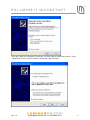
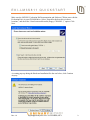
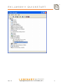
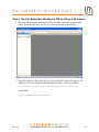
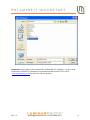
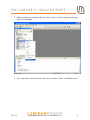
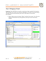
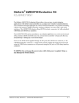
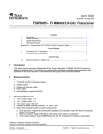
EKI-LM3S811 QUICKSTART Stellaris® LM3S811 Evaluation Kit for IAR Embedded Workbench® The Stellaris® LM3S811 Evaluation Kit provides a low-cost way to start designing with Stellaris® microcontrollers using IAR System’s Embedded Workbench tools. The LM3S811 Evaluation Board (EVB) can function as either a complete evaluation target, or as a debugger interface to any external Stellaris® device. The included USB cable is all that is needed to provide power and communication to the host PC. LM3S811 Evaluation Board Requirements You have a PC, with a USB interface, running Microsoft® Windows 2000, XP, or 2003 You have the Stellaris® LM3S811 Evaluation Kit Documentation and Software CD CAUTION: There is a known electrical issue with the FT2232 device that is used in the on-board In Circuit Debug Interface (ICDI). Some USB hubs can cause the device to misbehave, with symptoms ranging from failed enumeration to corrupt data transfers. If you experience trouble when using the on-board ICDI, try connecting the USB cable directly to one of the USB ports on your PC or laptop. The LM3S811 Evaluation Board is configured for immediate use. To power the EVB, use the USB cable supplied in the kit. Connect the mini-b (smaller) end of the USB cable to the connector labeled “USB” on the EVB. Connect the other end (Type A) to a free USB port on your host PC. The USB is capable of sourcing up to 500 mA for each attached device, which is sufficient for the evaluation board. If connecting the board through a USB hub, it must be a powered hub. When you plug in the EVB for the first time, Windows starts the Found New Hardware Wizard and asks if Windows can connect to Windows Update to search for software. Select “No, not this time” and then click Next. Rev. 1.2 [email protected] ▪ 512-279-8800, ext. 3 1 EKI-LM3S811 QUICKSTART Next, the Found New Hardware Wizard asks you from where to install the software. Select “Install from a list or specific location (Advanced)” and click Next. Rev. 1.2 [email protected] ▪ 512-279-8800, ext. 3 2 EKI-LM3S811 QUICKSTART Make sure the LM3S811 Evaluation Kit Documentation and Software CD that came with the Evaluation Kit is in your CD-ROM drive. Select “Search for the best driver in these locations,” and check the “Search removable media (floppy, CD-ROM…)” option. Click Next. A warning pops up during the Hardware Installation like the one below; click Continue Anyway. Rev. 1.2 [email protected] ▪ 512-279-8800, ext. 3 3 EKI-LM3S811 QUICKSTART Windows finishes installing the drivers for “LM3S811 Evaluation Board A.” When the driver install is finished, the Found New Hardware Wizard window appears like the one below. Click Finish to close the dialog box. You have just installed the drivers for “LM3S811 Evaluation Board A.” The USB device built into the EVB is a composite USB device. After you click Finish, a new Found New Hardware Wizard appears asking to install drivers for another device. This is for the “LM3S811 Evaluation Board B” part of the composite USB device. Follow the same instructions as above to install the drivers for this device. The Found New Hardware Wizard appears one last time. This is to install the drivers for the “LM3S811 Virtual COM Port.” Again, follow the same instructions to install the drivers for this device. Now all of the hardware drivers for the LM3S811 Evaluation Board have been installed. These drivers give the debugger access to the JTAG interface and the host PC access to the Virtual COM Port. Quickstart Application The LM3S811 Evaluation Board comes preprogrammed with a quickstart application. Once you have powered the board, this application runs automatically. You have probably already noticed this running as you installed the drivers. A Luminary Micro and IAR Software splash screen appear on the OLED display for a few seconds before the application begins. Rev. 1.2 [email protected] ▪ 512-279-8800, ext. 3 4 EKI-LM3S811 QUICKSTART The quickstart application is a game in which you navigate a ship through an endless tunnel. Use the potentiometer (POT) to move the ship up and down, and the user pushbutton (USER) to fire a missile to destroy obstacles in the tunnel. Score accumulates for survival and destroying obstacles. The game lasts for only one ship; the score displays at the end of the game. Since the OLED display on the evaluation board has burn-in characteristics similar to a CRT, the application also contains a screen saver. The screen saver only becomes active if two minutes have passed without the user pushbutton being pressed while waiting to start the game (that is, the screen saver never appears during game play). An implementation of the Game of Life is run with a field of random data as the seed value. After two minutes of running the screen saver, the display turns off and the user LED blinks. Exit either mode of screen saver (Game of Life or blank display) by pressing the user pushbutton (USER). Press the button again to start the game. While the game is being played, a running tally of the score is output through UART0 of the LM3S811 microcontroller. UART0 is connected to the FTDI’s second serial channel. This serial channel is available to Windows as a Virtual COM port. To view the score, open up a terminal application such as HyperTerminal. Connect using COM#, where # is the number Windows has assigned the Virtual COM port. Set the serial connection to a baud rate of 115200, 8 data bits, no parity, 1 stop bit, and no flow control. To determine which COM# Windows has assigned to the Virtual COM port on the LM3S811 microcontroller, follow these steps: 1) From the Start Menu, select Control Panel, then double-click the System icon. 2) Select the Hardware tab. 3) Click on the Device Manager button. 4) Click on the + symbol to expand the Ports (COM & LPT) group. 5) “LM3S811 Virtual COM Part (COM#)” is listed as shown in the figure below. This COM# is the device you connect to using your terminal application. In this example, the COM port is COM6. Rev. 1.2 [email protected] ▪ 512-279-8800, ext. 3 5 EKI-LM3S811 QUICKSTART Rev. 1.2 [email protected] ▪ 512-279-8800, ext. 3 6 EKI-LM3S811 QUICKSTART IAR Embedded Workbench® This quickstart shows you how to install the KickStart™ version of the IAR Systems Embedded Workbench tools, and then how to use it to build and run an example application on the Luminary Micro Stellaris® LM3S811 Evaluation Board. Step 1: Install Embedded Workbench 1. Insert the LM3S811 Evaluation Kit Documentation and Software CD into the CDROM drive of your computer. If Autoplay is enabled on your PC, this automatically opens up the index.htm file in your default web browser. If not, use Windows Explorer to open it manually. 2. Click on the Tools button and then the IAR Logo to start the setup program. If the setup program does not start, use Windows Explorer to view the files on the CD, and double-click the EWARM-KS-CD-441A.exe file located in the Tools\IAR\ directory. 3. Click on the “Install Embedded Workbench” link to begin the tool installation. You will be required to register with IAR to receive license information (by clicking on “Get License”) before you can install the tools. If you have any questions about installation, follow the instructions detailed in the IAR quickstart documentation, which can be accessed by clicking “QuickStart Installation Information” in the main window of the splash screen. Rev. 1.2 [email protected] ▪ 512-279-8800, ext. 3 7 EKI-LM3S811 QUICKSTART Step 2: Start the Embedded Workbench IDE and Open a Workspace 1. Start the IAR Embedded Workbench IDE by selecting it from the Windows Start Menu. When the IDE loads, it will have a blank screen that looks like this: 2. Open the workspace file ek-lm3s811.eww by clicking File>Open>Workspace. The workspace file is located in the IAR installation directory, which by default is: C:\Program Files\IAR Systems\Embedded Workbench 5.0 Kickstart in the folder: ARM\src\examples\Luminary\LM3Sxxx Rev. 1.2 [email protected] ▪ 512-279-8800, ext. 3 8 EKI-LM3S811 QUICKSTART Important: For the most recent version of the StellarisWare™ workspace, use the version found on the LM3S811 Evaluation Kit Documentation and Software CD or check www.luminarymicro.com for the latest software updates. Rev. 1.2 [email protected] ▪ 512-279-8800, ext. 3 9 EKI-LM3S811 QUICKSTART Step 3: Build the StellarisWare™ Components and Example Project 1. Before any of the examples can be built, the StellarisWare™ file must be compiled. To build the file, right click on the driverlib project and select “Make”. Rev. 1.2 [email protected] ▪ 512-279-8800, ext. 3 10 EKI-LM3S811 QUICKSTART 2. Right-click the hello example, and select “Set as Active” to make the project the target project for debugging. 3. Now, right-click on the hello project once more and select “Make” to build the project. Rev. 1.2 [email protected] ▪ 512-279-8800, ext. 3 11 EKI-LM3S811 QUICKSTART Step 4: Debugging a Project Important: The LMI FTDI driver interface is much slower than a standard J-Link interface, and is intended to be used for tool evaluation. Upgrading to a J-Link for your custom design will allow for much faster download speeds. The J-Link cannot be used with the EKI-LM3S811. 1. Begin a debug session by selecting “Debug” under the Project menu. You will see the debugger download and verify the application, and stop execution at the main() function. Rev. 1.2 [email protected] ▪ 512-279-8800, ext. 3 12 EKI-LM3S811 QUICKSTART 2. From here, you can examine and modify memory, program variables, and processor registers, set breakpoints, step, and other typical debugging activities. To run the program, select “Go” from the Debug menu, or click on the “Go” button (icon). 3. The application starts running, and you should see the text “Hello World!” output to the OLED display of the evaluation board. Step 5: Build and Run Additional Example Programs There are several additional example projects listed in the EK-LM3S811 workspace. If you would like to build another example project, right-click the project and select “Set as Active” to make it the target for debugging. Then, right-click and select “Make”. Follow the instructions from Step 4 to debug the application. The quickstart application that came preloaded on the evaluation board (the game) is the qs_ek-lm3s811 project listed with the examples. Conclusion You have now installed the IAR Embedded Workbench IDE, and used it to build, load, and run an example application on the Luminary Stellaris® LM3S811 Evaluation Board. From here, you can experiment with the debugger or start creating your own application using the EK-LM3S811 workspace and projects as examples. Rev. 1.2 [email protected] ▪ 512-279-8800, ext. 3 13 EKK-LM3S811 QUICKSTART References The following references are included on the Stellaris® LM3S811 Evaluation Kit Documentation and Software CD and are also available for download at www.luminarymicro.com: Stellaris® LM3S811 Evaluation Kit User's Manual, Publication Number EK-LM3S811 StellarisWare™ Software, Order Number SW-LM3S StellarisWare™ Peripheral Driver Library User’s Guide, Publication Number SW-DRLUG Stellaris® LM3S811 Microcontroller Data Sheet, Publication Number DS-LM3S811 In addition, the following website may be useful: IAR website at http://www.iar.se Support Information For support on Luminary Micro products, contact: [email protected] +1-512-279-8800, ext. 3 Copyright © 2007-2009 Luminary Micro, Inc. All rights reserved. Stellaris is a registered trademark and the Luminary Micro logo is a trademark of Luminary Micro, Inc. or its subsidiaries in the United States and other countries. ARM and Thumb are registered trademarks, and Cortex is a trademark of ARM Limited. Other names and brands may be claimed as the property of others. Luminary Micro, Inc. 108 Wild Basin Rd., Suite 350 Austin, TX 78746 Main: +1-512-279-8800 Fax: +1-512-279-8879 http://www.luminarymicro.com [email protected] Rev. 1.2 3/3/2009 IMPORTANT NOTICE Texas Instruments Incorporated and its subsidiaries (TI) reserve the right to make corrections, modifications, enhancements, improvements, and other changes to its products and services at any time and to discontinue any product or service without notice. Customers should obtain the latest relevant information before placing orders and should verify that such information is current and complete. All products are sold subject to TI’s terms and conditions of sale supplied at the time of order acknowledgment. TI warrants performance of its hardware products to the specifications applicable at the time of sale in accordance with TI’s standard warranty. Testing and other quality control techniques are used to the extent TI deems necessary to support this warranty. Except where mandated by government requirements, testing of all parameters of each product is not necessarily performed. TI assumes no liability for applications assistance or customer product design. Customers are responsible for their products and applications using TI components. To minimize the risks associated with customer products and applications, customers should provide adequate design and operating safeguards. TI does not warrant or represent that any license, either express or implied, is granted under any TI patent right, copyright, mask work right, or other TI intellectual property right relating to any combination, machine, or process in which TI products or services are used. Information published by TI regarding third-party products or services does not constitute a license from TI to use such products or services or a warranty or endorsement thereof. Use of such information may require a license from a third party under the patents or other intellectual property of the third party, or a license from TI under the patents or other intellectual property of TI. Reproduction of TI information in TI data books or data sheets is permissible only if reproduction is without alteration and is accompanied by all associated warranties, conditions, limitations, and notices. Reproduction of this information with alteration is an unfair and deceptive business practice. TI is not responsible or liable for such altered documentation. Information of third parties may be subject to additional restrictions. Resale of TI products or services with statements different from or beyond the parameters stated by TI for that product or service voids all express and any implied warranties for the associated TI product or service and is an unfair and deceptive business practice. TI is not responsible or liable for any such statements. TI products are not authorized for use in safety-critical applications (such as life support) where a failure of the TI product would reasonably be expected to cause severe personal injury or death, unless officers of the parties have executed an agreement specifically governing such use. Buyers represent that they have all necessary expertise in the safety and regulatory ramifications of their applications, and acknowledge and agree that they are solely responsible for all legal, regulatory and safety-related requirements concerning their products and any use of TI products in such safety-critical applications, notwithstanding any applications-related information or support that may be provided by TI. Further, Buyers must fully indemnify TI and its representatives against any damages arising out of the use of TI products in such safety-critical applications. TI products are neither designed nor intended for use in military/aerospace applications or environments unless the TI products are specifically designated by TI as military-grade or "enhanced plastic." Only products designated by TI as military-grade meet military specifications. Buyers acknowledge and agree that any such use of TI products which TI has not designated as military-grade is solely at the Buyer's risk, and that they are solely responsible for compliance with all legal and regulatory requirements in connection with such use. TI products are neither designed nor intended for use in automotive applications or environments unless the specific TI products are designated by TI as compliant with ISO/TS 16949 requirements. Buyers acknowledge and agree that, if they use any non-designated products in automotive applications, TI will not be responsible for any failure to meet such requirements. Following are URLs where you can obtain information on other Texas Instruments products and application solutions: Products Amplifiers Data Converters DLP® Products DSP Clocks and Timers Interface Logic Power Mgmt Microcontrollers RFID RF/IF and ZigBee® Solutions amplifier.ti.com dataconverter.ti.com www.dlp.com dsp.ti.com www.ti.com/clocks interface.ti.com logic.ti.com power.ti.com microcontroller.ti.com www.ti-rfid.com www.ti.com/lprf Applications Audio Automotive Broadband Digital Control Medical Military Optical Networking Security Telephony Video & Imaging Wireless www.ti.com/audio www.ti.com/automotive www.ti.com/broadband www.ti.com/digitalcontrol www.ti.com/medical www.ti.com/military www.ti.com/opticalnetwork www.ti.com/security www.ti.com/telephony www.ti.com/video www.ti.com/wireless Mailing Address: Texas Instruments, Post Office Box 655303, Dallas, Texas 75265 Copyright © 2009, Texas Instruments Incorporated