1
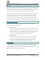
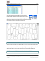
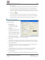
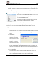
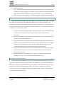
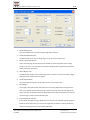
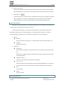
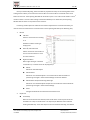
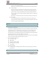
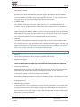
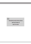
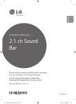
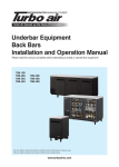
SHANGHAI LISHOU INFO. TECH. CO. LTD. 1 / 14 LSProject User Manual Book Shanghai Lishou Info. Tech. CO. LTD. 2014.01.01 Contents Overview ................................................................................................................................................... 2 Computer Hardware Mode ............................................................................................................... 2 Main Interfaces................................................................................................................................. 2 Software Interfaces And Functions ........................................................................................................... 3 Main Control Window ...................................................................................................................... 3 Menu Button ............................................................................................................................. 4 Working Folder ......................................................................................................................... 4 File List Box ............................................................................................................................... 5 PLT Basic Settings Dialog .......................................................................................................... 5 Preference Settings Dialog ........................................................................................................ 6 System Menu and About Dialog ............................................................................................... 7 Adjust Projector ................................................................................................................................ 8 Set The Frame Information ....................................................................................................... 8 Adjusting Window .................................................................................................................. 10 Projecting Window ......................................................................................................................... 10 Appendix ................................................................................................................................................. 12 Appendix I – System Requirement .................................................................................................. 12 Appendix II - Installation ................................................................................................................. 12 Appendix III – Dongle ...................................................................................................................... 13 Room 206 No.8 Lane 489 Quyang Road, Shanghai China PC:200081 www.lsccm.com TEL:(86)21-60731190, 60731191 SHANGHAI LISHOU INFO. TECH. CO. LTD. 2 / 14 Overview LSProject is the visual positioning system for the cutting machine developed by our company. It can be applied either with our other camera input system and nesting system together or itself alone. LSProject can correct the deviation of a projector which is used to show the nesting result on a cutting machine. LSProject can also move and rotate the PLT data to match the material position. To cut the leather and other irregular material, the user can do nesting and other work in some other nesting system and software tools in advance. Upon completion, the cutting job can be down by showing the result onto the cutting machine via projector by using LSProject and then placing the material on the machine corresponding the position of the showing. Another working procedure is to place the material on the cutting machine first and then move/rotate the PLT data in LSProject to match the position of the material. After matched, export the modified PLT data and do cutting work. Computer Hardware Mode LSProject supports two kinds of displaying configurations of the computer: dual display mode monitor and projector; single projector mode. Dual Display Mode Requires the computer has ability to expand the desktop to a second monitor, such as the general laptop computers which has a external VGA or newer video export port. By setting nd the display mode of the 2 monitor (projector) to extend the desktop, LSProject will show st the main control window on the main monitor (the 1 monitor) and the full screen nd projecting window or adjusting window on the projector (the 2 monitor). Single Display Mode nd When the computer has only one video output or the 2 monitor is set as COPY mode, LSProject can only show all windows in the current screen for either the main control window or the projecting window and adjusting window. When projecting/adjusting window is shown, the main control window will be covered underneath. Main Interfaces The following images are the main interface windows of the software. The projecting / adjusting nd window will be shown maximized on the projector (the 2 monitor) automatically if available. Otherwise, it will be shown on top of the main control window in the current monitor. Please read the following chapters for the detail functions of each window. Room 206 No.8 Lane 489 Quyang Road, Shanghai China PC:200081 www.lsccm.com TEL:(86)21-60731190, 60731191 SHANGHAI LISHOU INFO. TECH. CO. LTD. 3 / 14 There will be a floating tool box window on top of the Adjusting / Projecting window. The buttons inside are used to confirm or cancel operations or save PLT data after offset moving or rotating. These floating tool box windows can be closed by setting in preference dialog and the same operations can be done by keyboard or context menu. Software Interfaces And Functions LSProject will get into the Main Control Window after start up. The user must adjust projector before load and show a PLT file in the projector window. By clicking the menu command [Adjust Projector] of the button on top left of the Main Control Window, you can get into the Adjusting Window to do the adjusting work. After that, you can select a PLT file to show it in the Projecting Window. The displaying result on the cutting machine will be match the dimension and position. Main Control Window Room 206 No.8 Lane 489 Quyang Road, Shanghai China PC:200081 www.lsccm.com TEL:(86)21-60731190, 60731191 SHANGHAI LISHOU INFO. TECH. CO. LTD. 4 / 14 Main Control Window of LSProject contains menu button for many of the operations, [working folder] and file list. Menu Button The Menu Button on top left of the window will set the latest menu item being used as the default action. The menu has the following command items: 1. Load PLT Import PLT file in format of HPGL and show up the Projecting Window with this PLT data inside. This operation will launch a Open File Dialog to open a file from outside of the [working folder] without changing it. 2. Save PLT After offset moving, rotating operations in the Projecting Window, the result of the PLT data is needed to be saved to a PLT file and be used to cutting on the machine. By this command, user can do save the current PLT data. NOTE: The PLT data modification will be kept before another PLT file is loaded even the Projecting Window is closed. 3. Adjust Projector Shows up the Adjusting Window. 4. PLT Basic Settings Shows up the dialog window of PLT Basic Settings. 5. Preference Settings Shows up the dialog window of Preference Settings. Working Folder LSProject maintain a [Working Folder] as the data file location. All PLT files will be listed in the file list box. You can change the [Working Folder] by the path control on top right of the Main Window. Room 206 No.8 Lane 489 Quyang Road, Shanghai China PC:200081 www.lsccm.com TEL:(86)21-60731190, 60731191 SHANGHAI LISHOU INFO. TECH. CO. LTD. 5 / 14 Clicking the icon button at right of the control will launch the browsing dialog in which you can choose a new path. The file list box will be update after a new [Working Folder] is set. File List Box The File List Box occupies the most area of the Main Control Window in which all PLT files in [Working Folder] will be listed. You can do the following operations here: 1. Open And Project A File Left Clicking a PLT file in the list will load and show it in the Projecting Window. The Projecting Window will be shown up if it is in hidden. 2. Sort Left Clicking of the mouse on the header of the File List Box will sort the file list by the column being clicked in ascending / descending order. The header columns are Name, Size, Type and Modified (date-time). 3. Double Left Clicking Of Mouse This will forward a request to the Windows System to deal with the file being clicked. In most of the cases, the system will try to find an application registered to be able deal with file type of [.plt]. PLT Basic Settings Dialog PLT Basic Settings is for the PLT IO module. These are PLT generic parameters: 1. Resolution The length of unit 1 of the PLT data. The default value is the standard of HPGL – 1/40mm. Some cutting machine uses 0.01mm. 2. Landscape This will cause an export of the HPGL command – RO90 at the beginning of the created PLT file. It is used to switch the direction of X and Y. 3. Need Positioning Rectangle A rectangle is required for purpose of matching position on some cutting machine or by habit of some operating workers. Here this option will enable the rectangle exportation or identifying at import. The pen ID is used to create or read such Positioning Rectangle. And this rectangle will not be affected when you do moving or rotating operations. Room 206 No.8 Lane 489 Quyang Road, Shanghai China PC:200081 www.lsccm.com TEL:(86)21-60731190, 60731191 SHANGHAI LISHOU INFO. TECH. CO. LTD. 4. 6 / 14 Adjust By Real Sizes There might be some error between the real position on the cutting machine and the data of PLT commands for reason of mechanical distortion and so on. By this adjusting logic, such error can be calibrated. The design width and height are the values of PLT data. The real width and height are measuring values of the drawing or cutting result on the machine. 5. Load And Save These two buttons can save the values in the dialog into a file (.json) or load them back from a file saved before. This function is helpful when you need to use the same settings in a different software. It is easy and help to keep the same parameters without error. Preference Settings Dialog Preference Settings Dialog contains the settings for using habit: 1. Background Color The background color of the Projecting / Adjusting Window. 2. Matching At According this setting, the PLT data loaded will be located at the right position. This parameter must to be same to the setting of the cutting machine. The value can be any of: Absolute Coordinate, Align By Center and any point of edge middle or corner of the rectangle. 3. Measure Unit The length unit of the length values at showing time. The default is mm. NOTE: you need click OK to make the unit changing take effect to the length values (STEP) below in the same dialog. 4. Step of Keyboard Moving In Projecting Window, you can move the PLT command lines by arrow keys. Here defines the offset length of each key stroke – with or without holding SHIFT key. 5. Rotation Step In Projecting Window, you can rotate the PLT command lines by CTRL + arrow keys. Here defines the rotation angles of each key stroke – with or without holding SHIFT key. 6. PLT Drawing Settings You can set the displaying color, opacity and line width basing the Pen ID of the PLT command lines. Room 206 No.8 Lane 489 Quyang Road, Shanghai China PC:200081 www.lsccm.com TEL:(86)21-60731190, 60731191 SHANGHAI LISHOU INFO. TECH. CO. LTD. 7. 7 / 14 Hide Control Toolbox This option can disable the floating Control Toolbox window of the Adjusting and Projecting Windows. You can use this option to avoid the trouble that the floating Toolbox window covers something. And the functions of the Toolbox buttons can be done by keyboard or right click context menu. Enter is OK; Esc is Cancel. System Menu and About Dialog Clicking at the icon at top left of the Main Window can show up the system menu. There is a command – [About] besides the other basic commands of Windows System. The menu command of Microsoft Windows System are easy to be understood which are about the movement, minimizing, maximizing and closing the window. [About] command will launch the About Dialog of this application in which you can do the following works or get more information beside read the information of software version and copyright: 1. Software Information Box Here the serial number of the dongle and information about software modules will be listed if any. The serial number of the dongle is useful when you are trying to get technical support. 2. Upgrade Dongle Dongle can be upgraded remotely for some cases like opening more modules. For a trial dongle, it can be extended the trial time. The upgrading information is transferred by a special file called Key File supplied by the dealer of vender. Presses this button and select a Key File in the launched Open File Dialog will apply the Key File onto the dongle. The result of the action will be reported at the end. If successes, you need to restart the application to make the changed taking effect. Once used, the Key File cannot be used any more. 3. Set Dongle Password The dongle can have a password. The maximum length is 16 characters. Once set, the software can only start after the correct password supplied. This password is set in the dongle so that the password is needed even you switch to another computer. Room 206 No.8 Lane 489 Quyang Road, Shanghai China PC:200081 www.lsccm.com TEL:(86)21-60731190, 60731191 SHANGHAI LISHOU INFO. TECH. CO. LTD. 4. 8 / 14 Interface Languages All the interface languages supported are listed in the dropdown list. You can selected one to switch the interface languages. You need to restart the software to make the setting take effect. NOTE: some of the interface elements (such as system menu) are from Windows System and will not be changed here. You need to change the language of Windows System. Adjust Projector You need to adjust the projector at the first time to use this software or when there is distortion error after some time of using. The purpose of this adjusting is to recover the distortion of the showing of the projector on the cutting machine work table. The distortion may come from the error of projector installation position and angle. It also might come from the error of the camera lens and the keystone correction of the projector. 1. Executes the command of [Adjust Projector] from the submenu of the menu button will get into the Frame Information Dialog in which you need to input or load the proper information. 2. Exports the PLT file according the parameter of the frame. Draw or cut it on a paper fixed on the working table of the cutting machine. 3. Presses the OK button in the former Frame Information Dialog and gets into the Adjusting Window. The Adjusting Window will show to the projector display and in full screen mode. If nd nd there is the 2 extended monitor in the computer, Adjusting Window will be on the 2 monitor. Otherwise, it will be in the current one and be shown on the top. 4. There will be a grid of red blocks in column and rows basing the Frame Information. Move these red blocks on the screen to make the projected shadow matching the drawing or cutting hole on the paper. 5. Click the [OK] button in the floating Control Toolbox or press Enter key to confirm the adjusting result. Then the PLT command lines can be shown correctly. Set The Frame Information The Frame information defines the size of each positioning block (the red block), the dimension of the blocks and other necessary parameter values. The software can create a PLT file basing these information. Adjusting the displaying of the positioning blocks to match the output of the PLT on the cutting machine, we can get a transforming map for the projector to show PLT command lines correctly. There are also the setting for the angle of projector installation and the view angle of the human to do the adjust in this dialog. Room 206 No.8 Lane 489 Quyang Road, Shanghai China PC:200081 www.lsccm.com TEL:(86)21-60731190, 60731191 SHANGHAI LISHOU INFO. TECH. CO. LTD. 1. 9 / 14 Size Of Working Area This size should be the size of the cutting range of the machine. 2. Coordinate Of Bottom-Left The bottom left corner of the cutting range. It is (0, 0) in most of the cases. 3. Measuring Size Of Projector This is the measuring size of the projector shadow on the working table of the cutting machine. This size is not must but it will help the adjusting working efficient by initialize a netter position for the blocks. 4. Grid of Block Frame This defines the number of the positioning blocks in columns and rows. Generally a bigger cutting machine needs some more blocks. 5. Size Of Position Block Size of each positioning block. It should be square in most of the cases. 6. Block Margin This margin is the distance the outer blocks from the range edge of the cutting machine. That means the first and the last blocks of a row will be placed from left and right by this margin and then all other blocks will be put between them with event distance in this row. The same logic is used in vertical direction also. 7. Proj. Rotation; OP. Rotation In case of the installation angle is different from normal or the available operating angle is limited to some special way, you can set the angle here so that the arrow key stroke will match the moving direction in the Adjusting Window. Room 206 No.8 Lane 489 Quyang Road, Shanghai China PC:200081 www.lsccm.com TEL:(86)21-60731190, 60731191 SHANGHAI LISHOU INFO. TECH. CO. LTD. 8. 10 / 14 Export Frame To PLT Specifies the PenID for the Frame line and do export the Frame to a PLT file. By clicking the [PLT Settings] button, you can get into the dialog to set the basic parameters for the PLT IO. 9. Load And Save These two buttons can save the values in the dialog into a file (.json) or load them back from a file saved before. This function is helpful when you need to use the same settings in a different software. It is easy and help to keep the same parameters without error. Adjusting Window The blocks grid will be displayed in the Adjusting Window once it is showed up. Each block has a number pair (i, j) for reference of the column and row. To do the adjust successfully, You need to move these blocks in the window to make them matching the position of the corresponding blocks on the paper which are drawn or cut by the machine basing the exported PLT file. The detail of the operation are as the followings: 1. Mouse Left Click Selects a block when clicking on it; or deselects block when clicking on empty area. Left Drag Drags to move a block. 2. Keyboard Arrow Keys When a block is selected, the key stroke will move it one pixel on the direction of the key. When there is no block selected, all blocks will be moved on pixel for each key stroke on the key direction. Add, Minus Keys (+, -) Increases or decreases the size of the block displayed. ‘W’, ‘S’, ‘A’, ‘D’ Select the next block on the direction of the key stroked. WSAD are for up, down, left and right. If there is no current selection, the block at bottom left will be selected. ESC Cancel and exit. ENTER Conform and exit. Projecting Window Room 206 No.8 Lane 489 Quyang Road, Shanghai China PC:200081 www.lsccm.com TEL:(86)21-60731190, 60731191 SHANGHAI LISHOU INFO. TECH. CO. LTD. 11 / 14 Once you did the Adjusting, the PLT file will be projected correctly on the working table of the cutting machine when you click the file in the List Box or use the Load PLT command of the menu nd button to load one. The Projecting Window will be shown up if it is not. And it will be shown in the 2 monitor if there is such one with setting to extend the desktop on it. Otherwise, the Projecting Window will be shown on top of the current monitor. In working mode of place the material first and then adjust the PLT command line data, you need to move and rotate the PLT command lines in the Projecting Window by the following way: 1. Mouse Left Click Selects a command line if clicking on it. Deselects all when clocking at empty place. SHIFT 或 CTRL+Left Click Add or remove the command line into or from the selection. This is for multi-selection. Right Click Menu When right clicking at a selected command line, a context menu will be popped up: Delete Deletes all selected objects. Delete Others Deletes all non-selected objects. The command lines with the PenID of positioning rectangle in the PLT Basic Settings will also be deleted. Delete Others Except Positioning Rectangle Deletes all non-selected objects except the command lines with the PenID of positioning rectangle in the PLT Basic Settings. PenN Changes the PenID of the selected command lines to N. 2. Keyboard Arrow Keys When some command lines selected, each stroke of the arrow key will move the selected lines a step on the direction. The step may be different with or without holding the SHIFT key. These two steps can be set in Preference Dialog. The default Room 206 No.8 Lane 489 Quyang Road, Shanghai China PC:200081 www.lsccm.com TEL:(86)21-60731190, 60731191 SHANGHAI LISHOU INFO. TECH. CO. LTD. 12 / 14 values are: 0.5mm and 10mm (SHIFT). When there is no selected command line, the key stroke will move all command lines. CTRL+Arrow Keys When some command lines selected, each stroke of CTRL+arrow key will rotate the selected lines an angle on the direction – up and left is counterclockwise; down and right is clockwise. The angle may be different with or without holding the SHIFT key. These two angles can be set in Preference Dialog. The default values are: 1 degree and 5 degree (SHIFT). When there is no selected command line, this operation will rotate all command lines. ESC or ENTER Close the Projecting Window. The editing of offset movement and rotation will be kept till the next file is loaded. So that you can do export the changed PLT data to a file even after closing the Projecting Window. Appendix Appendix I – System Requirement 1. Operation System Requirement This software is basing MS Windows System. It can run on any computer or laptop installed with the Window System version of Windows XP ( with Service Pack 3 or above), Windows Server 2003 (with Service Pack 2 or above), Windows Server 2008, Windows Vista or Windows 7 or above. Windows7 is recommended for the higher disk accessing efficient and safty. Windows 98, Windows Me, Windows NT and Windows 2000 are not supported. When the software is installed in a 64 bits Windows, it will run in the 32 bits sub-system WOW64. So that not all of the potential of the 64 bits system can be used. 2. 3. Minimum Hardware Requirement CPU: Pentium V 1GHz RAM: 512 MB Empty Hard Disk Space: 10MB Monitor Resolution: 1024x768 1 Free USB Port Recommend Hardware nd 2 displaying card or a displaying card with ability to connect the projector set to extend the desktop on it. Appendix II - Installation Room 206 No.8 Lane 489 Quyang Road, Shanghai China PC:200081 www.lsccm.com TEL:(86)21-60731190, 60731191 SHANGHAI LISHOU INFO. TECH. CO. LTD. 1. 13 / 14 Administrator Privilege The installation package of the software needs the privilege of administrator if you are working in Windows 7 (also Vista). Please follow the guidance of system prompt when you do installation. To use this software, you need to plug on the dongle - security device - on your computer. If you still get the report of no security device, please find help from your dealer. 2. Installation Folder The installation program will use a folder under root of disc "C: " as the default folder to do installation. You can change this folder to other place as you like. But if you are in a Windows 7 system (or Vista), please do not select the folder under your "Program Files". The reason is this software is designed as “GREEN” software so that it will keep many settings under the installation folder. Windows 7 (also Vista) has strict limitation for the accessing to the folder under "Program Files". So that we suggest you just use the default path to do the installation. 3. Uninstall There will be an Uninstall link created in the program folder in the start menu of Windows. But this uninstall program can only remove all the files created by the install program. Other files and folders created when you run the software will not be removed by the uninstall program. If you want to clean all files created, you can just delete the folder directly. Appendix III – Dongle 1. No Driver The dongle we used needs no driver so that the installation will be easier. 2. Keep Dongle Plugged DO NOT REMOVE THE DONGLE DURING YOU WORKING. YOUR EDITING WORK CANNOT BE SAVED ANY MORE ONCE YOU UNPLUGED THE DONGLE AND USED ON ANOTHER COMPUTER. 3. Check Dongle Information Please read chapter of [About]. You can get the information when you get into the About Dialog of the software in which all information of the dongle will be listed. The information may including serial number, trial time and modules of the software. If the software and dongle supports more than one interface languages, a dropdown list box with all languages will appear. You can select one of them and restart the software to switch to the languages you want. 4. Upgrade Dongle and Key File In most of the cases, such as to extend the trip time or to open new modules, you can get it done by a key file remotely without return back the dongle to your dealer. What you need to do is to get a correct Key file from your dealer. You may need to tell your dealer the serial number of your dongle when you ask for the key file. Supplying the key file when it is asked or get into About Dialog and press the [Upgrade Dongle] Room 206 No.8 Lane 489 Quyang Road, Shanghai China PC:200081 www.lsccm.com TEL:(86)21-60731190, 60731191 SHANGHAI LISHOU INFO. TECH. CO. LTD. 14 / 14 button directly will let the software applies the Key File onto the dongle. Once it prompts succeed and restarts the software, you can check the changes upon the dongle. The Key File is unique for only a specific dongle and can be used only once. 5. Set Password The dongle supports password protection. After clicking the [Set Password] button in About Dialog and inputting a password, you need type the correct password when you starts the software next time. Without the correct password, you cannot get into the software anymore. Please don’t forget the password. Otherwise you need to send the dongle back to your dealer to fix it. Room 206 No.8 Lane 489 Quyang Road, Shanghai China PC:200081 www.lsccm.com TEL:(86)21-60731190, 60731191