1
B8961 and B8962
Brushless Servo
Smart Drives
Operator’s Manual
P/N PCW-4744, Rev 1.9
This manual covers the following
IDC Products:
B8961-1 axis Brushless Servo
Smart Drive
B8962-2 axis Brushless Servo
Smart Drive
Table of Contents
Table of Contents
PRODUCT AND MANUAL OVERVIEW ................................................................1
SHIPPING CONTENTS......................................................................................................................2
QUICK START......................................................................................................3
KEYPAD OPERATION .........................................................................................7
KEYPAD FEATURES ..........................................................................................................................7
Keypad Har dware Features .......................................................................................................9
Dipswitches ..........................................................................................................................9
Contrast ................................................................................................................................9
Remote Mounting .................................................................................................................9
KEY PAD PROGRAMMING MENU STRUCTURE...........................................................................10
RUN Menus ..................................................................................................................................
10
PROG
Running Programs..............................................................................................11
JOG
Jogging the Motor ..............................................................................................11
TEST
Test and Debugging functions ...........................................................................12
EDIT Menus ..................................................................................................................................
13
PROG
Creating and Editing Motion Programs ..............................................................13
SETUP
System Set-up Menu ...........................................................................................14
POS
Reset Current Position to Zero ..........................................................................15
LIST
List User Memory Usage ....................................................................................15
TUNING Servo Tuning.......................................................................................................15
HELP Menus ..................................................................................................................................
16
At the Main Menu ...............................................................................................................16
At the Menus and Sub-Menus .............................................................................................16
In the Editor .......................................................................................................................16
COPY Menus .............................................................................................................................16
PROG
Copy a Program to Another Program.................................................................16
TO PAD Upload Memory to Keypad................................................................................17
FROM
Download Memory to Control...........................................................................17
DEL Men u .....................................................................................................................................
17
RUN-TIME OPERATOR INTERFACE................................................................................................17
CONFIGURING YOUR SYSTEM ........................................................................19
SETUP MENU..................................................................................................................................20
MOTOR Motor/Drive Configuration .....................................................................................20
ENC
Encoder Configuration ............................................................................................22
MECH
Mechanical Configuration .........................................................................................
24
I/O
Input & Output Configuration ...................................................................................
28
JOG
Jogging Configuration .............................................................................................36
HOME
Homing Configuration ............................................................................................37
PROG
Prog r am-Run Configuration ..................................................................................39
RS232
RS-232C Configuration ............................................................................................40
MISC
Miscellaneous Configuration Parameters .................................................................40
TUNING YOUR SERVO SYSTEM ....................................................................................................43
Compensator ......................................................................................................................44
RS-232C Users.....................................................................................................................44
Key Pad Tuning .........................................................................................................................45
Keypad Tuning Menu Tree ..................................................................................................45
GAINS
Setting the Servo Gains ......................................................................................45
B8961 and B8962 User Manual
Toggle Tuning Stimulus.......................................................................................................46
Monitor Monitor Port .........................................................................................................46
PROGRAMMING YOUR APPLICATION ............................................................47
SMART DRIVE PROGRAMMING OVERVIEW .................................................................................47
CREATING OR EDITING PROGRAMS WITH THE KEYPAD ...........................................................47
COMMAND SUMMARY ..................................................................................................................48
VARIABLES AND ARITHMETIC .......................................................................................................49
VARIABLES ......................................................................................................................................49
LEGAL VERIABLE NAMES ...............................................................................................................49
BUILT-IN VARIABLES .......................................................................................................................50
NON-VOLATILE VARIABLES............................................................................................................52
ARITHMETIC OPERANDS AND EQUATIONS .................................................................................53
BOOLEAN OPERATORS- & (AND), (OR)......................................................................................53
LOGICAL OPERATIONS ON EXPRESSIONS ...................................................................................54
INCREMENTING AND DECREMENTING VARIABLES.....................................................................54
EXPRESSIONS .................................................................................................................................54
MULTI-AXIS OPERATION ...............................................................................................................55
SIMPLE GO COMMANDS ...............................................................................................................55
TYPICAL PROGRAMMING EXAMPLES...........................................................................................58
READING AN ANALOG INPUT .......................................................................................................59
CONFIGURING AN ANALOG OUTPUT ..........................................................................................60
PROGRAMMING COMMANDS ..........................................................................61
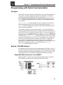
PROGRAMMING WITH SERIAL COMMUNICATION ........................................91
SECTION 1:RS-232 PROTOCOL.....................................................................................................91
Making RS-232C Connections to the S6961/2 ........................................................................91
Troubleshooting Serial Command Problems ..........................................................................92
Daisy Chaining Smart Drives ..................................................................................................92
SECTION 2:APPLICATION DEVELOPER SOFTWARE.....................................................................93
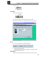
Installing Application De veloper .............................................................................................93
Common Installation Err ors and Remedies ..............................................................................94
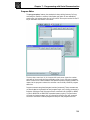
SECTION 3:USING APPLICATION DEVELOPER ™ ..........................................................................95
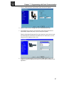
Setup Wizard ..............................................................................................................................95
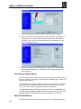
Axis Setup .................................................................................................................................99
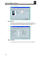
I/O Setup..................................................................................................................................102
Miscellaneous (Misc) Setup ....................................................................................................103
File Men u ................................................................................................................................104
Prog r am Editor .......................................................................................................................105
View Configuration ................................................................................................................106
Communications ....................................................................................................................106
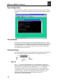
Run Menu .................................................................................................................................107
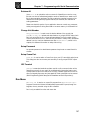
SECTION 4:RS-232C IDEAL™ COMMAND REFERENCE...............................................................108
Overview .................................................................................................................................108
Sample File ..............................................................................................................................108
Command Syntax ...................................................................................................................110
Serial Setup Commands ..........................................................................................................112
Serial Prog ramming Commands ............................................................................................118
Commands Not Used In Host Mode .......................................................................................120
Serial Immediate Status Commands ......................................................................................122
Serial Supervisory Commands ...............................................................................................127
Table of Contents
HARDWARE REFERENCE ...............................................................................131
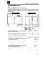
B8961 AND B8962 SMART DRIVE MOUNTING...........................................................................131
FK1 and FK2 Fan Kit .............................................................................................................132
RPACK-1 and RP ACK-2 Mounting Installation .......................................................................132
Remote Keypad Mounting .......................................................................................................132
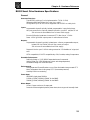
B8000 SMART DRIVE HARDWARE SPECIFICATIONS..................................................................133
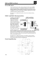
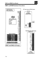
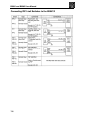
B8961 AND B8962 HARDWARE CONNECTIONS ........................................................................134
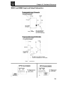
B8961 AND B8962 INPUT AND OUTPUT SCHEMATICS .............................................................135
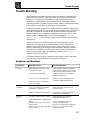
TROUBLE SHOOTING .....................................................................................137
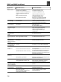
SYMPTOMS AND SOLUTIONS .....................................................................................................137
IDC PRODUCT SUPPORT ...............................................................................139
FACTORY AUTHORIZED DISTRIBUTORS ....................................................................................139
REGIONAL OFFICES .....................................................................................................................139
TOLL FREE TECHNICAL SUPPORT...............................................................................................139
CAD LIBRARY...............................................................................................................................139
WARRANTY & REPAIRS ..................................................................................139
INDEX..............................................................................................................140
APPENDIX A: IDC ACTUATOR RATIOS..........................................................143
CONFIGURING INCH & MM UNITS ON SMART DRIVES USED WITH IDC ACTUATORS..................143
Methods For Configuring Ratio ...............................................................................................
143
IDC ACTUATOR RATIOS...............................................................................................................143
N, T, R2, R3, R4, NM, RM Series ...............................................................................................143
APPENDIX B: EMC INSTALLATION ................................................................147
ELECTROMAGNETIC COMPATIBILITY (EMC) INSTALLATION GUIDELINES .............................147
Introduction .............................................................................................................................147
Separation and Shielding ..................................................................................................148
Grounding.........................................................................................................................149
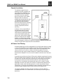
Physical Installation ................................................................................................................150
AC Power Line Filtering ...........................................................................................................150
Motor Output P ower Cable Shielding ......................................................................................151
Declaration of Conformity ......................................................................................................152
APPENDIX C: FAN KIT OPTION .....................................................................153
APPENDIX D: REGEN PACK OPTION ............................................................155
Chapter 1 - Product and Manual Overview
Product and Manual Overview
IDC’s B8961 and B8962,one and two axis Smart Drives,combine a DSP based
servo amplifier with a powerful,but easy to use,machine controller.We offer a
single axis version (B8961) and a dual axis version (B8962).The B8962 has two
axes of independently configurable amplifiers.Both products incorporate IDC’s 5
amp continuous,10 amp peak,120/230VAC,digital servo amplifier with a
motion/machine controller in a single,compact package.Up to 24 digital I/O are
available to control other machine functions.Up to 8 of these can be configured as
analog inputs or outputs.
The B8000 Series Smart Drives feature a 5 amp continuous, 10 amp peak, digital
brushless servo drive using state of the art DSP technology to provide high
performance closed loop servo control to a wide variety of permanent magnet
brushless and brushed servo motors and actuators offered by Industrial Devices
Corporation.
The Vector Control used by the servo amplifier offers higher bandwidth torque
and velocity control when compared with sinusoidal or hall effect commutated
brushless servo amplifiers.This results in an expanded torque speed curve that
leads to higher throughput machines.The easy servo setup offered by the keypad
configuration or via Application De veloper gives high speed,high torque,brushless
servo motor performance,with an ease of use rivaled only by a stepper system.
IDC’s IDeal ™ Smart Drives provide excellent value when your application calls for
any of the following:
• A small,1-2 axis machine controller
• A “motion node”to a master PLC or PC
• A cost effective operator interface
• Thumbwheel data inputs
• Flexible I/O capabilities
• On-board OPTO I/O modules (analog or digital)
The B8000 Series Smart Drives also feature a programming/operator interface.The
intent of the Smart Drive’s k eypad is to allow you to quickly and easily configure
and program your system.Initial setup and configuration,in most cases,will require
only a few minutes using the keypad.While Smart Drives fully support PC based
RS232 programming,the setup and configuration sections of this manual often
emphasize the keypad approach.RS232 commands and setup definitions are in a
separate chapter.We strongly recommend using a keypad with your first B8000
Series Smart Drive application. You will also find it an invaluable troubleshooting
and machine commissioning aid during subsequent applications.
The following manual has been designed to help you successfully install,program
and operate your IDeal Programmable Smart Drive System.Each section of the
manual emphasizes the common theme “Ease of Use”.If you have any questions
that this manual does not adequately answer, please contact our factory application
engineers.
The manual begins with this Overview, followed by a Quick Star t chapter to help
you quickly confirm basic system operation.Next the manual describes
Communication with Your Control via the keypad interface.RS-232 interface
details are covered in Chapter 7, RS-232 Operation .
1
B8961 and B8962 User Manual
Chapter 4 covers the procedure for Configuring Your System to your specific
equipment and application requirements. It includes step-by-step keypad instructions
on scrolling through and entering setup parameters.This chapter covers initial motor
settings,I/O configuration,and defining the mechanics of your system.IDC’s
Windows based Application De veloper also follows the same menu structure
described here. .
Chapter 5, Programming Your Control , provides detailed program and application
examples and strategies.Other topics include variable usage,user menus,math
functions,and analog I/O. Our IDEAL ™ command language is generally regarded as
the easiest motion control langua ge in the industr y. It is both easy to remember
and intuitive,without sacrificing flexibility or power.
In Chapter 6, Command Ref erence, this alphabetical listing of Smart Drive commands
explains in detail syntax, ranges,defaults, and provides programming examples.
Chapter 7, RS-232 Operation , is for users who plan to use the Smart Drive in an
RS232 hosted mode,or who wish to program and configure the drive via RS232.
IDC’s Application De veloper program follows a standard Windows dialog box
structure to make configuring and programming the Smart Drive control straight
forward.This section also covers RS232 command syntax and definition for users
who are not using Windows.
The Har dware Reference chapter provides detailed I/O schematics,as well as
motor drawings,cables and specifications.The Troubleshooting chapter lists a
series of common application problems along with their symptoms and solutions.
Included with this manual is the Application De veloper cd-rom. IDC’s Application
Developer and Servo Tuner software are automatically installed on your hard drive
by running the setup program on the Application De veloper cd-rom.This disc also
includes a readme file containing the latest information on software features.Many
demo programs are included with AppDeveloper.
If you cannot find the information that you need in this manual,please contact the
Applications Department.(800) 227-1066.
Shipping Contents
1. B8961 or B8962 Smart Drive control
2. 120 VAC power cable
3. Application Developer software cd-rom
4. Installed OPTO modules (optional)
5. Fan Kit (optional)
Note:Units ordered as B8961NPs or B8962NP do not include the following keypad
items:
1. Keypad programming/operator interface (Part #FP220)
2. Keypad remote extension cable (6 ft)
3. Keypad remote mounting gasket
2
Chapter 2 - Quick Start
Quick Start
The purpose of the Quick Start chapter is to help an experienced motion control
user quickly set-up and bench test a B8000 Series Smart Drive with an IDC
supplied motor/encoder package.The following directions assume that the user is
familiar with servo motors,encoders,servo amplifiers,servo controls,and their
related electrical connections.Please refer to Chapter 4, “Configuring Your
System” if you have questions on any of these procedures.
For ease of set-up, we recommend that you use a keypad, and in this chapter it is
assumed that a keypad is used for set-up, even if an RS232 connection will be used later.
Caution: All connectors are KEYED to prevent “backwards”
installation. The connectors should fit snugly, but do not need to
be forced.
Caution: Do not plug the motor/encoder connector into the drive
until instructed. The motor and encoder can be damaged by an
incorrect motor setting.
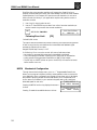
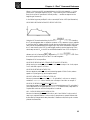
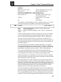
Apply Power
Connect the B8000 Series Smart Drive to 120VAC
+0.0000
+0.0000
using the supplied AC power cable and connector.
00000000 00000000
The AC power input terminals are labeled and
located at the top of the Smart Drive.When power is
applied,the display briefly shows Model number and Software Revision,then
changes to the Main Display.The Main Display continuously shows the position of
each axis on the top line and the status of Inputs 1-8 and Outputs 1-8 on the
bottom line.
Select the Motor Type
1.
2.
3.
4.
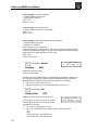
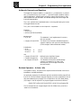
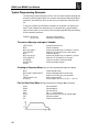
------ á EDIT â -----Press the EDIT key. Press SETUP (F2),then MOTOR PROG SETUP POS
(F1),then TYPE (F1).
The display should show NONE.Use the á and â Axis One Motor Type
keys to change the motor choice.If you have a
B23:110 VAC
B8962,use the ß and à arrows to change to axis
two to verify the motor choice.
Once the proper motor and volta ge level has been
selected,press ESC to save your choices.
You will be prompted to Enable each axis.Choose YES (F1).
If using a non-IDC motor, please call the factory for details on obtaining a motor
data file for your motor. If you already have this custom motor data file, see the
Using Non-IDC Motor section of Chapter 7, RS-232 Operation .
3
B8961 and B8962 User Manual
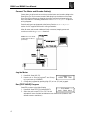
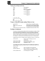
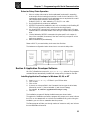
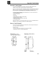
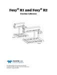
Connect The Motor and Encoder Cable(s)
Power down the drive and connect the pre-wired motor and encoder cables to the
Smart Drive.The 20 pin motor/encoder cable plugs into the bottom of the Smart
Drive.The MS connectors are keyed at the motor end.See the diagram below for
more information.If necessary, please refer to the Har dware Reference chapter for
wiring diagrams.
End-of-travel inputs are jumpered at the factory. See the Har dware Reference
section for IDC supplied limit switch wiring schematics.
After all motor and encoder cables are firmly connected, reapply power and
continue on with the Quick Star t directions.
Caution: The motor will be
enabled when the drive is
powered up.
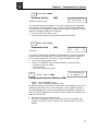
Jog the Motor
1.
2.
3.
Press RUN. Press JOG (F2).
------ RUN -----Press the ß or à key to jog (and á and â keys
PROG JOG TEST
to jog axis two on the B8962).
Change the Jog Speed by pressing High (F2) or Low (F1) and jog again.
Run [TEST MOVE] Program
Press ESC to return to the Main Display.
------ TEST MOVE -----1. Press RUN. Press TEST(F3).Press MOVE(F3)
Axis 1 Both Axis 2
2. Select the axis to test.(F1,F2,or F3) The axis
selected will move forward and backward one distance unit.(Distance units
default to motor revolutions.)
4
Chapter 2 - Quick Start
Create and Run a Simple Program
Press ESC to return to the Main Display.
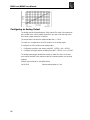
1. Press EDIT. Press PROG (F1). Enter 1.(Edit program #1.)
AC1
Press F2 & 2 & 1 & ENTER
VE10
Press F1 & 2 & 1 & 0 & ENTER
DI3
Press F2 & 1 & 3 & ENTER
GO
Press F1 & 3 & ENTER
EN
Press F3 & 6 & ENTER
2. Press ESC to save the program and return to the Main Display.
3. Press RUN, then PROG (F1),then enter 1.(Run program #1.) The program
should move the motor 3 revolutions.
Discrete Input Test
Connect a 12” test wire to one of the COM screw terminals found on the side of
the drive.One by one,touch the test lead to each Input screw terminal and verify
that the input status shown on the Main Display toggles between 0 and 1.
Discrete Output Test
1.
2.
3.
4.
Press RUN. Press TEST (F3). Press OUTPUT (F2)
Press the ß or à key to select an output number.
Press the â or á to turn the output ON or OFF.
Press ESC to leave this menu.The outputs will return to their state prior to
entering the test mode.Please use caution when manually toggling outputs
connected to live devices.No software interlocks are observed during this test.
The OPTO position’s default configuration is as an input.Please see Configuring
Your System for information on changing these to Outputs.You will then be able
to toggle their state from this screen.
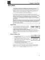
Where to go from here?
Successfully completing these steps confirms the basic operation of your system.At
this point, you may want to refer to the following sections for more information:
•
•
•
•
•
•
•
•
•
•
•
Hardware connections
Configuring Your System
IDC Actuator Gear Ratios
Non-IDC’s motor operation
Drive mounting
Fan Kit and RPACK connections
I/O software configuration
I/O hardware schematics
Basic keypad operation
Programming examples
RS232 connection and usage
p.134
p.19
p.25
p.21
p.131
p.132
p.28
p.135
p. 7
p.58
p.91
5
Chapter 3 - Keypad Operation
Keypad Operation
This chapter is meant to familiarize a first time user with the basics of IDC’s
keypad operation.IDC’s keypad functions fall into two categories. The keypad
functions first as a programming and troubleshooting tool.Secondly, it functions as
an operator interface.Operators can run programs,make menu choices,or be
prompted to enter data via the keypad number keys.
The first section of this chapter, Keypad Features , defines the basic function of
each button on the keypad.The second section, Menu Structur e, gives the
programmer a broad overview of how the keypad’s setup and programming menus
operate and fit together. Detailed information about each step parameter is
presented in Configuring Your Control .
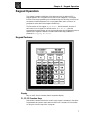
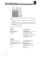
Keypad Features
Display
Easy to read,2 line,40 character, back-lit supertwist display.
F1, F2, F3 Function Keys
Used as Menu selectors.Used with numeric keys to select commands in the editor.
Programmable as operator menu selections.See the FK command for information
on using the function keys within a program.
7
B8961 and B8962 User Manual
RUN
Runs a Program, Jogs an axis,or accesses Test/Debugging functions like Program
Trace mode,and amplifier Enable/Disable/Reset.
EDIT
Edits setup parameters,programs,tuning (servos only),and resets position counter.
Also accesses program listing and teach mode. (Teach mode will be implemented
in a future software r evision.)
HELP
Provides help on keys,menus and command syntax.
COPY
Copies one program to another within a unit.Copying a complete application,
including all programs,setup parameters and motor configuration information.
Smart Drive to Smart Drive copying,via the keypad,will be implemented in a
future software release.
DEL
Deletes characters in the editor, or entire programs from memory.
Arrows (ß, à, and á, â)
Scroll through menu options,setup choices and programs in the editor.Also used
to move an axis in jog mode.
Decimal Point
Used to enter fixed point numbers.
Comma
Used in multi-axis controls to separate axis command parameters.Also part of the
syntax in message and variable prompt commands.
ALPHA
Alpha plus a numeric key selects the first letter on that key. Press the numeric key
more than once to select second or third characters. For example,Alpha+1+1
selects B.Other ASCII symbols,such as the >< and á characters can be selected
with Alpha using the á and â arrow keys.
ENTER
Selects a choice and enters a space in the editor.
Sign (+/-)
Selects the direction of motion in programs and can be used in math expressions.
ESC
Stops a program,backs up a menu level,also used for exiting and saving programs
while in the editor.
Numeric Keys (0-9)
Enters numbers.Used with Alpha to select characters.Used with F1-F3 to enter
commands in the editor.
8
Chapter 3 - Keypad Operation
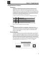
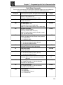
Keypad Hardware Features
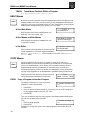
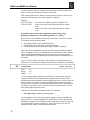
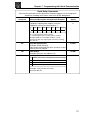
Dipswitches
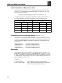
A bank of four dipswitches on the back of the keypad provide a way to lock
operators out of various keypad access levels.See the chart below for switch
assignments.If access to a menu level is denied,pressing that key will have no
effect. For example,if 1 is on,and 2 is off, the operator will be able to stop motion,
and program execution,(by pressing the escape key) but will not be able to access
the RUN menus to select another program to run.This is a hardware inhibit,and is
independent of any software,or setup parameter in the Smart Drive. Power must
be cycled before keypad dipswitch changes take effect.
In addition,access to the jog menu can be enabled or disabled from software.
SW1
off
off
on
on
SW2
off
on
off
on
Function Level
Full keypad functionality
No access to RUN, ESC,EDIT, COPY, DEL menus
No access to RUN, EDIT, COPY, DEL menus
No access to EDIT, COPY, DEL menus
Switch 3 and 4 are reserved for future functionality.
Contrast
On the back of the keypad,there is a single,plastic, flat head screw driver
adjustable,potentiometer.This is used to adjust the contrast on the LCD display. If
the Smart Drive and keypad were purchased together, this adjustment has been
made by IDC.Some adjustment may still be needed to accommodate unusual
lighting or viewing angles.
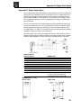
Remote Mounting
The keypad can easily be remote mounted and sealed to NEMA 4 specifications by
using the included mounting gasket and 6 foot communication cable.The gasket
should be installed with its adhesive side to the enclosure.A pressure seal is formed
between the gasket and the keypad,while the adhesive maintains the seal between
the enclosure and the gasket.The keypad communicates with the Smart Drive via
RS-232 so this cable can be extended if needed.At longer distances,users may have
to provide a separate 5 VDC supply to power the keypad.Complete keypad
drawings and pinouts can be found in the Har dware Reference chapter.
Back of Keypad Detail drawing
9
B8961 and B8962 User Manual
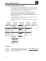
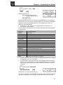
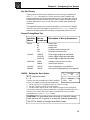
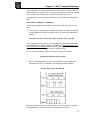
Key Pad Programming Menu Structure
Most operations from the Keypad are menu-driven.A menu consists of a title bar
on the top display line and as many as three options (or sub-menus) at a time on
the bottom display line.Each option is positioned over one of the function keys.
Pressing a function key will select the corresponding option.
If a menu has more than three options,arrows will appear in the title bar
indicating that there are more options which are not displayed.Pressing the
appropriate arrows (indicated on the display) will cycle through all options
associated with the menu. To leave a menu,without making a selection,or to back
up one menu level,press ESC.
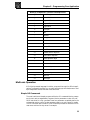
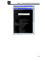
The following tree shows the Menus which are accessible from the Main Display
by pressing RUN, EDIT, HELP, COPY, and DEL keys.
NOTE:ESC backs up one menu in SETUP, and returns the user to the Main Display
elsewhere.
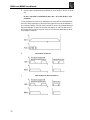
RUN
EDIT
HELP
COPY
DEL
PROG: Run programs,
by name or number.
PROG: Edit/Write
programs, most
commands are listed
on the keypad.
At Main Menu:
Provides help on the
function of each key.
PROGRAM: Copies
programs within a
control.
JOG: Jog either axis
at low or high speeds
using submenu and
arrow keys
SETUP: Configure
system and operating
limits.
At Menus:
Provides help on how
to move about menus.
TO PAD: Uploads a
controls memory to a
keypad.
TEST: Run programs
in trace mode,
amplifier shutdown
and reset, test
outputs, and moves.
POS: Sets current
position to a desired
value.
At Sub-Menus:
Explains setup
choices.
FROM: Downloads
keypad memory to a
control.
LIST: Directory of
stored programs,
memory usage and
available space.
In the Editor:
Provides command
descriptions.
PROGRAM: Deletes a
program.
TUNING: Servo tuning
via keypad, or set-up
for PC-based tuning.
TEACH: Teach move
positions
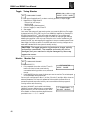
RUN Menus
RUN
10
Pressing the RUN key displays a second set of RUN
sub-menus.Access the sub-menus by pressing the
function keys F1,F2,and F3,which are below PROG,
JOG and TEST respectively.
------ RUN -----PROG JOG TEST
Chapter 3 - Keypad Operation
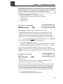
PROG
Running Programs
Run an existing program by program number, by
á RUN PROGRAM â
pressing:
>5
1. PROG(F1)
2. Program number 1-199 using numeric keys
(1-400 available with the 30k expanded memory option)
3. ENTER
Run an existing program by name by pressing:
--á RUN PROGRAM â-1. PROG(F1)
> 12 GRIND
2. á and â keys to scroll through the list of available
programs until you find the program you want
3. ENTER
JOG
Jogging the Motor
Jog either axes by pressing:
JOG AXIS 1 +0.0000
1. RUN
<LO> HIGH
2. JOG(F2)
3. ß and à keys to move axis 1
á and â keys to move axis 2 on a B8962.
Note:The á and â keys will also jog Axis 1 on a single axis unit.
Change between Low and High speeds with the F1 and F2 keys. Jog speeds and
accelerations can be changed in the JOG \ SETUP menu.
“Jog”an incremental distance by:
JOG AXIS 1 +0.0000
1. RUN
Dist.: .01
2. JOG (F2)
3. Entering a number (i.e.,0.012).
4. Pressing and releasing an arrow key will make the motor move this distance.
The arrow pressed determines the direction of the move.
5. Repeat 3 and 4 until at desired position.
Additional pushes of arrow keys will jog the same distance until either, F1,F2,or F3
is pressed.This feature is intended for very fine, final positioning.The incremental
jog speed is therefore fixed at a very low speed.
11
B8961 and B8962 User Manual
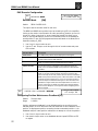
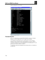
TEST
Test and Debugging functions
TRACE
The trace features allows you to de-bug programs by
á TRACE PROGRAM â
sequentially executing one program command at a
>_
time.
Press:
1. RUN \ TEST \ TRACE
2. Enter the program name or number
3. ENTER
The top line displays the program number, the
PR:5 LP:1 GS:0
number of nested loops,and the number of nested
DI8000
routines.The bottom line shows the command to be
executed when you press ENTER.Each time you
press ENTER,the displayed command will be executed.Pressing ESC halts program
execution.TRACE mode is not currently supported during homing operations.
OUTPUT
This feature allows you to test the control’s outputs,
Test Output #4
as well as the devices to which they are connected,
ßá
ON
âà
by forcing them on and off. Press:
1. RUN \ TEST \ OUTPUT
2. ß à keys to scroll through outputs 1-8,and any OPTO positions configured as
outputs.
3. á â keys to turn the output on and off
Please use caution when connected to live devices.The Outputs will revert to their
original state when ESC is pressed.
NOTE:The OPTO position default to Inputs.They must be configured as outputs
from the SETUP / I/O / OPTO menu before being accessible from this test utility.
See Configuring Your System for details.
MOVE
This selection moves your motor shaft one user unit forward and backwards.This
allows you to verify basic motor, encoder, and amplifier operation.
Press: RUN \ TEST \ MOVE,and select the axis to move.Pressing the axis Function
key will start the move.
SHUTDN
Selecting SHUTDN (shut down) allows you to
ß Drive 1 Disabled à
enable,disable or reset axis 1 or axis 2 (B8962).
ENABLE DISABLE RESET
When a drive is disabled,the amplifier is off and your
motor has no power.The shaft can be manually rotated relatively easily. RESET returns each drive to its power-on condition.
Existing set-up parameters are restored.
Press:
1. RUN \ TEST \ à \ SHUTDN
2. ENABLE,DISABLE or RESET
12
Chapter 3 - Keypad Operation
RS232 Serial Communications
RUN
> TEXT > RS232
---- Test Connection----TRANSMIT RECEIVE
This feature allows for testing of the terminal serial communications port through
the keypad.
Testing Serial Transmission:
1. From the Test Connection menu press the F1 key to
select the TRANSMIT option
Test String ‘ABC123’
Transmitting....
2. The SmartDrive will now transmit the string ”ABC123” every 5 seconds.
Testing Serial Receive:
1. From the Test Connection menu press the F3 key to
select the RECEIVE option.
Data Received
2.Any character received on the terminal port will be displayed on the keypad.
ENCODER
To be implemented in a future version of software.
EDIT Menus
EDIT
Pressing the EDIT key reveals three sub-menus called
PROG, SETUP and POS.
------ á EDIT â -----PROG SETUP POS
Pressing the â key reveals three more EDIT
sub-menus called LIST,TUNING and TEACH.
------ á EDIT â -----LIST TUNING TEACH
Access the PROG, SETUP, POS,LIST,TUNING and TEACH sub-menus by pressing the
appropriate function key. See descriptions of each of these sub-menus below.
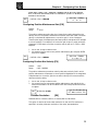
PROG
Creating and Editing Motion Programs
This menu allows you to edit an existing program,or
begin entering a new program from the keypad.
-á EDIT PROGRAM â-> 5
Use the numeric keys to enter a program number to
start a new motion program,or use the á and â
keys to scroll through the list of existing programs,and press ENTER.
You are now viewing your IDeal ™ motion program in
the keypad program editor and are ready to edit your
program.
AC3 VE1 DI8000 GO
EN
See Programming Your Application for more information on editing IDeal motion
programs with the keypad.
13
B8961 and B8962 User Manual
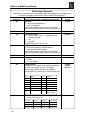
SETUP
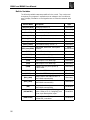
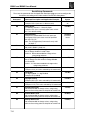
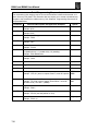
System Set-up Menu
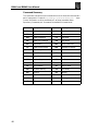
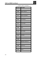
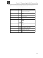
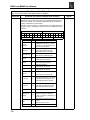
The following table shows the structure within the SETUP menu. For complete
descriptions of each system parameter in the SETUP sub-menu,see Configuring
Your System .
14
SubMenus
Set-up
Description of Set-up Parameters
Parameters
MOTOR
TYPE
D-RES
DIR
Motor type
Drive Resolution
Direction of travel
ENC
MODE
E-RES
FOL-ERR
Select open/closed loop mode
Encoder resolution
(fixed at 8000 on IDC motors)
Following error
MECH
DIST
RATIO
BKLASH
VEL
VMAX
ACCEL
Distance Units
Scale distance to preferred user units
Electronic backlash compensation
Speed units
Critical speed limit
Acceleration units
I/O
INPUTS
OUTPUTS
OPTOS
Input functions
Output functions
OPTO module configuration
JOG
ACCEL
LO-VEL
HI-VEL
ENABLE
Jog acceleration
Low jog velocity
High jog velocity
Enable/disable jog in RUN menu
HOME
EDGE
SWITCH
OFFSET
FINAL
Edge of home switch
Type of home switch
Position counter offset
Final homing direction
PROG
PWR-UP
SCAN
DELAY
Program to run on power up, if any
How to scan program select inputs
Program Select de-bounce time
RS232
ECHO
UNIT#
Echo characters
Serial address
MISC
DISPLAY
STOP-RATE
TEST
Display mode
Decel rate when stop input activated
Enable Test Menu
Chapter 3 - Keypad Operation
POS
Reset Current Position to Zero
POS is a quick way to reset the motor’s current
position to (absolute) zero,which can be a helpful
setup and debugging tool.
Press:
1.
2.
LIST
Reset Position?
YES
NO
EDIT \ POS
YES (F1) or NO (F3)
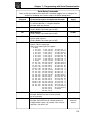
List User Memory Usage
LIST provides a way to view your program memory usage.Your IDC Smart Drive
will accept up to 199 IDeal ™ motion programs of 1024 characters each,with 6K
bytes of program storage available (up to 400 programs available with the 30k
expanded memory option).
Pressing:
1. EDIT \ â \ LIST
Displays the number of programs stored in your
Smart Drive.
DIRECTORY áMOREâ
PROGRAMS: 18
2.
â
Displays the total amount of memory your
programs have used.
DIRECTORY áMOREâ
BYTES USED: 1186
3.
â
Displays the number of bytes of memory you
still have available.
DIRECTORY áMOREâ
BYTES FREE: 4958
4.
âââ ... â
Displays the number of bytes being used by each
of your programs.
DIRECTORY áMOREâ
5 <untitled>: 56 bytes
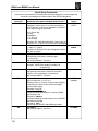
TUNING
Servo Tuning
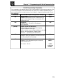
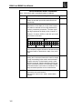
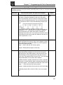
The following shows the structure of the TUNING menu.See Configuring Your
System for a complete description of servo tuning and the parameters in the
TUNING sub-menus.
SubMenus
Set-up
Description of Set-up Parameters
Parameters
AXIS 1
GAINS
TOGGLE
MONITOR
NOHUNT
WINDUP
Alter servo gains for AXIS 1.
Start step function generator to view system
response.
Configure oscilloscope monitor port.
Enable between-move Anti-Hunt feature.
Enable Inertial Anti-Windup feature.
AXIS 2
Tune Axis 2 (same set up parameters as
AXIS 1 above)
RS232
Configure Smart Drive for tuning via
RS-232C port and IDC’s Servo Tuner
15
B8961 and B8962 User Manual
TEACH
Teach Move Positions Within a Program
To be implemented in a future version of software.
HELP Menus
HELP
Whenever you have a question using the keypad,pressing HELP will display a help
message related to the menu you are currently in.Help messages are often several
lines,which you can scroll through using the á and â keys.When you are finished
reading a help message,pressing ESC returns you to the menu.
At the Main Menu
- - - - á HELP â - - - Use RUN key to...
HELP explains the functions available when you
press any of the non-numeric keys.
At the Menus and Sub-Menus
HELP explains the selections available from your
current menu location.
In the Editor
This option is used to
select the motor type...
á COMMAND SUMMARY â
AC Acceleration
HELP provides a brief alphabetical command list.Full
syntax and details on command usage are available in
the IDeal ™ Command Reference of this manual,or from HELP in the Application
Developer editor.
COPY Menus
COPY
Copying programs from one name (or number) to another can save you a
significant amount of time when prog ramming your Smart Drive.The keypad has
its own non-volatile memor y, which allows you to upload the memory (motion
programs,set-up and tuning parameters) of one Smart Drive, reconnect and
download the memory contents to another unit.Note:Smart Drive to Smart Drive
copying via the keypad is not yet implemented in the B8000 Series of Smart Drives.
Pressing the COPY key brings up three choices that
can be accessed by pressing the function keys.
PROG
- - - - - COPY - - - - PROG TO PAD FROM
Copy a Program to Another Program
This selection allows you to copy any existing
program to a new program name.
1.
2.
3.
á SOURCE PROGRAM â
>5
Press PROG
Enter the source program number. Or, if you wish, you can scroll through your
list of program names by using the âá keys.
Press ENTER
Then you are asked to enter the new program.If the target program already exists,
you will have to delete it first (see DEL).
Then
á TARGET PROGRAM â
>5
1. Enter the target program.
2. Press ENTER
Remember to change the name of the copied programs to avoid subroutine call
conflicts.
16
Chapter 3 - Keypad Operation
TO-FROM PAD
Copy to-from Keypad
-----------COPY---------The COPY TO-FROM feature has been implemented
PROG TO PAD FROM
which allows user setup and programs to be downloaded to and from the keypad.A special keypad
cable (PCS-5004) provides a +5V power supply and a 9 pin D style connector for
communications with Application Developer™.COPY TO-FROM requires
SmartDrive version v6.00 or higher and keypad firmware v2.60 or higher.
Contact IDC for firmware upgrades and cable information
Copy TO Keypad:
1.Press F2 key to select TO PAD (Note:Unit address is not saved in keypad)
Copy FROM Keypad:
1.Press F3 key to select FROM (Note:Unit address is not set from keypad transfer)
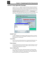
In order to use COPY TO-FROM with Application Developer™, connect the kepad to
the PC using cable PCS-5004 and select “Retrieve All”from the Application
Developer Communications menu to load data from the keypad and select “Send
All”from the Application Developer Communications menu to load data to the
keypad.See the Application Developer section in the S696X,B896X and 96X manuals for more information on using Application Developer.
DEL Menu
DEL
The DEL key lets you delete any motion program
á DELETE PROGRAM â
currently in your Smart Drive.
>_
Press:
1. DEL
2. Enter the number of the program to delete.Or, if you wish, you can scroll
through a list of existing program names by using the âá keys.
3. ENTER
Run-Time Operator Interface
Your keypad features an easy-to-read,2-line,40-character, back-lit display that can be
easily remote mounted to a panel and exposed to industrial NEMA 4 environments.
While motion programming and system configuration procedures using the keypad
are defined by IDC, run-time operation (i.e.how the machine operator will
interface with the Smart Drive) falls completely within the customer’s control.
Here are some of the operating functions you can program with the Smart Drive:
• Run a program on power-up,on input signal from a PLC,or RS-232C host
command
• Within a program,prompt the operator for any program variable (the number of
parts to run,size of parts,speed,etc.)
• Run a part or prog ram by name
• Lock-out operators from programming functions
For more information on programming your Smart Drive’s operator interface,see
the Programming Your Application and IDeal ™ Command Reference chapters.
17
Chapter 4 - Configuring Your System
Configuring Your System
This chapter presents a straight forward,intuitive procedure for Configuring Your
System to your specific equipment and application requirements.The following
configuration section contains detailed,step-by-step directions for customizing the
B8961 and B8962 to your specific application and mechanical requirements.IDC
recommends that even experienced users follow this procedure in its entirety.
Following all the SETUP steps will insure that no critical parameters are
overlooked.
The task of configuring your B8961 or B8962 Smart Drive system to a specific
application consists of customizing a number of software parameters to match the
mechanics of the system.These parameters include distance,acceleration and
velocity scaling as well as I/O configuration.Other than plugging in the
motor/encoder cable and connecting your I/O wiring,there are no hardware
settings on a B8961 or B8962 Smart Drive system.
All of the software configuration can be done via the keypad,or via RS232 using
Application De veloper.The Configuring Your System description presented here is
from a keypad user’s perspective,via the keypad menu structure and step-by-step
keypad instructions.
Application De veloper and RS-232C users will want to refer to this chapter for
detailed explanations of configuration parameters.Details on how to use IDC’s
Application De veloper can be found in the Chapter 7. For RS-232C terminal users,
non-Windows™ PC users,or PLC users,the equivalent 2-character ASCII
configuration commands are detailed in the RS-232 Command Reference section
Chapter 7,but the examples presented here are valid for all users.The 2-character
ASCII command appears in brackets next to the appropriate keypad menu choice
in this chapter. Application De veloper users will find that the Windows dialog
boxes under the Setup menu follow the keypad menu structure very closely.
Users who plan to create and download their own ASCII setup file will also find
this section useful.The RS-232 command that relates to the parameter being set is
in brackets below the keypad menu structure.RS-232 command syntax details are
in the RS-232 Command Reference section of Chapter 7.
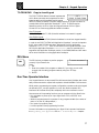
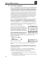
Each SETUP step follows the format of the example below:
In App Developer
click on SETUP/I/O
Keypad
strokes
needed to
get to the
input set-up
menu.
EDIT
RS-232 input
configuration
command
SETUP I/O
Input Defn
Default:UUUUUUUUUUUUUUUU
[ID]
IN1: unassigned
BBBBKREJUUUUßáâà
The function of each input is easily configured using the k eypad as described on the fol lowing page.
19
B8961 and B8962 User Manual
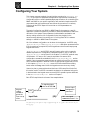
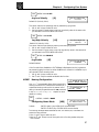
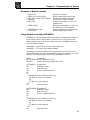
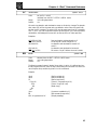
SETUP Menu
Pressing the EDIT key followed by the SETUP
function key reveals three menus.
Pressing â reveals a second and a third set of menus.
Each of these sub-menus are explained below.
NEW MOTOR CONFIGURATION
- - - á SETUP â - - MOTOR ENC MECH
- - - á SETUP â - - I/O
JOG
HOME
- - - á SETUP â - - PROG RS232 MISC
The structure of the motor type selection menu has
--- Motor Type --changed in order to accommodate the addition of
STEPER R-SERVO L-SERVO
the built-in linear servo motor files plust the expansion of the B servo motor series.The MOTOR TYPE
menu option now has three sub-menus: STEPER (for step motor drive parameters),
R-SRVO (for rotary ser vo motors) and L-SRVO (for linear servo motors).
Configuring Stepper Motor Type
EDIT
> SETUP > MOTOR > TYPE > STEPER
Default:
STEPPER
N/A
INDEXER
Axis One Motor Type
ßá STEPPER âà
(S696X)
(B896X)
(96X)
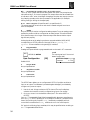
Configuring R-SRVO Motor Type [MT]
– Axis One R-Srvo Type –
EDIT
> SETUP > MOTOR > TYPE > R-SRVO
Default:
N/A
NONE
INDEXER
ßá B32:110VAC âà
(S696X)
(B896X)
(96X)
This option specifies the type of rotary servo motor connected to the B896X
SmartDrive and the operating voltage level.The motor parameters used for drive
configuration have been specifically tailored for IDC supplied rotary servo motors.
1.Use the ß and à keys to select an axis.
2.Use the á and â keys to scroll through the list of IDC’s rotary motors
3.Press the ESC key to select
None (Sets K ii and Kip gains to zero.)
B12:110VAC
B22:110VAC,B22:220VAC
B23:110VAC,B23:220VAC
B23H:110VAC,B23H:220VAC
B32:110VAC,B32:220VAC
B33:110VAC,B33:220VAC
B40:110VAC,B40:220VAC
B41:110VAC,B41:220VAC
B42:110VAC,B42:220VAC
BN21:110VAC
BN23:100VAC
BN31:110VAC
BN32:110VAC
H3:110VAC
H4:110VAC
or OTHER
Default:None.
Consult the factory if you intend to use a non-IDC motor. See Chapter 7, RS-232
Operation , for information on configuring a Smart Drive for a non-IDC motor.
20
Chapter 4 - Configuring Your System
CAUTION: If the motor type is set incorrectly the motor may be damaged.
Specifying the incorrect voltage will not damage anything, but different
current loop gains are used so system instability may result.
The safest way to change motor types is to:
1. Power up the control without the motor connected.
2. Change the Motor Type setup parameter to the new motor.
3. Remove power.
4. Connect the motor.
5. Re-apply power.
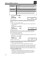
EDIT
SETUP MOTOR-D-RES
Motor Resolution
- Axis One Drive Res ßá 8000 counts/rev âà
[MR]
Default:B Motors = 8,000,H motors = 8,000,BN Motors = 4,000.
IDC’s B8961 and B8962 Smart Drives allow you to set a different drive input
resolution than the actual resolution encoder.This option specifies the input
resolution for each axis of your digital servo smart drive,in counts per motor
revolution.This is a very useful feature when retrofitting microstepping systems.
It is very important that the encoder resolution (E-RES) is set to your post-quadrature
encoder resolution.D-RES can be set at the users discretion.
1.
2.
Use ß and à keys to select an axis.
Use the áâ and ENTER keys to select from a list of drive resolutions available:
200,400,1000,2000,5000,8000,10,000,18,000,25,000,25,400,and
36000.
Your mechanics,and application needs will dictate the choice of D-RES. For
example,if you want to move in .1 degree increments,a D-RES choice of 18,000
will allow 50 motor steps per degree and prevent any resolution induced rounding
errors.
EDIT
SETUP MOTOR DIR
Motor Direction
- Axis One Motor Dir ßá POSITIVE âà
[MD]
Default: Positive
This option provides a convenient way to change which direction the motor
moves when you program a positive distance command.
When POSITIVE is selected as the motor direction,the EOT+ limit switch should
be wired so that moves in the plus direction (as shown on the keypad display, or
via the PA command) will activate the switch.When NEGATIVE is selected,the
EOT+ limit switch should be wired so that moves in the negative direction (as
shown on the keypad display, or via the PA command) will activate the switch.
1.
2.
Use ß and à keys to select an axis.
Use the áâ and ENTER keys to select a direction
21
B8961 and B8962 User Manual
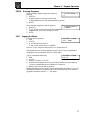
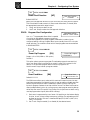
ENC Encoder Configuration
EDIT
SETUP ENC MODE
Encoder Mode
Default:
- Axis One Enc Mode ßá CLOSED LOOP âà
[EM]
SERVO CLOSED LOOP
This option sets the encoder mode for each axis.
The B8961 and B8962 servo position loops are closed by the DSP in the amplifier,
freeing up the motion control board to do other processing.Therefore, you can run
the servo in either “open loop”or “servo closed loop”modes.This allows you to
view (on the keypad display or via the PAn commands) either the commanded or
actual position in user units.All programmed moves are based on the Motor/Drive
Resolution setting (D_RES).
1.
2.
Use ß and à keys to select an axis.
Use the á and â keys to scroll through the list of encoder modes and press
ESC to select:
Encoder Mode
Description
OPEN LOOP
The OPEN LOOP position will be displa yed on the keypad.
OPEN-STALL
The OPEN LOOP position will be displayed on the keypad but the
encoder will be used for stall detection.
CLOSED LOOP
The encoder position is displayed on the keypad.All mo ves are
based on encoder position and stall detection is enabled.
SERVO-CLOSED
The encoder position is displayed on the keypad.All mo ves are
based on the commanded OPEN LOOP position and stall detection
is enabled.
CLOSED LOOP PM
The encoder position is displayed on the keypad.All mo ves are
based on encoder position,however, post move correction algorithms will keep the encoder position equal to the last commanded
OPEN LOOP position. Following error is still active while in CLOSED
LOOP PM mode.A following er ror will occur when the number of
correction steps exceeds the following error value.This allows the
SmartDrive to signal a fault when the displacement can not be corrected (i.e.the motor is stalled at an obstruction). Position maintenance will not attempt to correct position while navigating menus
with the keypad.
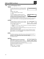
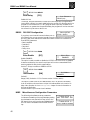
> SETUP > ENC > IN-RANGE > WINDOW
EDIT
- Axis One PM DeadBnd ßá 25 Steps âà
Configuring Position Maintenance Deadband [IR]
Default:
Range:
25 motor steps
0 - 99999
Position maintenance deadband is a user definable region surrounding the commanded position in which the motor shaft can reside and not be considered “out of
position”.A displacement position exceeding the last commanded position +/- the
deadband value,will cause position maintenance to attempt to correct the position.
1.
2.
22
Use ß and à keys to select an axis.
Use numeric keys to enter a new deadband value and press ENTER then ESC
to register.
Chapter 4 - Configuring Your System
NOTE: EDIT > SETUP > ENC > INRANGE > WINDOW and the IR serial command
have an alternate functionality with servo SmartDrive systems. See the B8961/2
manual for more details.
EDIT
- Axis One PMGain ß 10 à
> SETUP > ENC > PMGAIN
Configuring Position Maintenance Gain [PG]
Default:
Range:
10
1 - 32767
The position maintenance gain value is an integer factor usedin determining the
velocity at which the position maintenance correction move will travel.Correction
velocity is calculated as (displacement * correction gain) in units of steps/sec.
Therefore,the larger the displacement,the faster position maintenance will attempt
to correct position. For example,if the correction gain is set to 3 and an active displacement of 3200 steps occurs,the correction velocity will be (3 * 3200) = 9600
steps/sec.
1.
2.
EDIT
Use ß and à keys to select an axis.
Use numeric keys to enter a new position maintenance gain and press ENTER
then ESC to register.
- Axis One PMMax ß 1 RPS à
> SETUP > ENC > PMMAX
Configuring Position Max Velocity [PV]
Default:
Range:
1 RPS
0.005 - 9999999
The position maintenance maximum velocity value sets a velocity limit in which
position maintenance will attempt to correct position.Regardless of the magnitude
of displacement or cor rection gain,the correction velocity will never exceed the
maximum velocity setting.
1.
2.
Use ß and à keys to select an axis.
Use numeric keys to enter a new position maintenance max velocity in the
same units selceted in teh SETUP>MECH>VEL menu and press ENTER the ESC
to register.
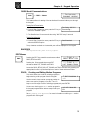
EDIT
- Axis One Encoder Res
ßá 4000 counts/rev âà
SETUP ENC E-RES
Encoder Resolution
[ER]
Default:8,000 for B motors,2,000 for H motors,4000 for BN Motors.
This option is used to set the encoder resolution for each axis.The resolution is
specified in encoder pulses per revolution of the motor, post-quadrature.
23
B8961 and B8962 User Manual
Specifying the wrong encoder resolution will prevent the Smart Drive from
properly communicating the motor and could damage it,as well as cause unstable
system behavior. For this reason,IDC fixes the encoder resolution for our servo
motors.Consult the factory if your application requires using another motor or
resolution encoder.
1.
2.
Use ß and à keys to select an axis.
Use the áâ and ENTER keys to select from a list of encoder resolutions,or
use the numeric k eys to enter the encoder resolution.
EDIT
- - Axis One Fol Error - ß
8000 steps
à
SETUP ENC FOL-ERR
Following Error Limit
[FE]
Default:8,000 counts
This option defines the maximum position following error allowed during motion.
A fault occurs when the error between the commanded and feedback signal
exceeds the Following Error value.
Range:0-524,000 step counts,0 = OFF
If a Following - Error occurs,the control will enter a fault state where:
• Any motion or program being executed is immediately terminated.
• The LCD Display will indicate “Following Error”,along with an explanation.
• A fault output will be generated if defined as a “Stall”or Fault output.
• The ESC key or a RESET (either an input or via RS-232) will need to be issued
before motion can occur.
MECH
Mechanical Configuration
Through the mechanical setup menu, your IDeal ™ Programmable Smart Drive
allows you to program in distance, velocity and acceleration units convenient for
your application.Once configured, your keypad will use these units in all display
and position reporting modes.This menu also allows you to compensate for a
known amount of backlash in your mechanical system,and to set a maximum
allowable speed for each axis.
-- á MECH SETUP â -DIST RATIO BKLASH
Pressing the MECH function key displays three menu
choices:
-- á MECH SETUP â -Pressing â reveals three additional menu choices:
24
VEL
VMAX
ACCEL
Chapter 4 - Configuring Your System
EDIT
SETUP MECH DIST
Distance Unit
- Axis One Dist Units ßá revs âà
[DU]
Default:Motor Revs
DIST is used along with RATIO to select your distance units and unit label.All
distance values specified in the system will be expressed in the units selected here.
The relationship between motor revolutions,system mechanics,and the distance
label chosen here is defined with the RATIO command defined below.
1. Use ß and à keys to select an axis.
2. Use the áâ keys to select distance units from:
• mils
• inch
• feet
• yards
• mm
• cm
• meter
• arcsec
• arcmin
• degrees
• radians
• grads
• steps
• %
• index
• revs
Notes:
• You can change DIST or RATIO at any time.Changing them will not change the
associated DI or DA values in a program.(i.e.DI100 will command a 100 inch
move instead of a 100 step move if the DIST units are changed from Steps to
Inches.)
• If steps is chosen,the control automatically fixes the RATIO (see below).
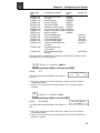
EDIT
SETUP MECH RATIO
Gear Ratio
- - Axis One Ratio - ßá
1 to 1
âà
[GR]
Default:1 to 1
The RATIO option is used to scale DI and DA moves to your preferred distance
units.RATIO sets the ratio of motor r evolutions per DIST unit . Up to 5 digits on
either side of the ratio can be entered to properly scale your DIST units.
1.
2.
Use ß and à keys to select an axis.
Use the numeric keys to enter a ratio
expressed as 2 integers.Ex:When programming in output shaft revolutions of
a 5:1 gearbox,enter “5 to 1” rather than
“1 to .2”
Notes:
• You can change DIST or RATIO at any
time.Changing them will not change the
associated DI or DA values in a program,
so all moves will change by the same fac tor that RATIO was changed.
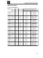
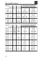
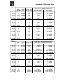
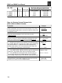
• If using an IDC supplied actuator, the
proper Gear Ratios for programming in
units of Inches and mm can be found in
Appendix A,directly following the Index.
25
B8961 and B8962 User Manual
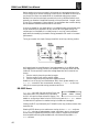
Units Example - Lead Screw System
• Desired distance units:inches
• Lead Screw:4 revs/inch
DIST = inch
RATIO = 4 to 1
Units Example - Rotary Index Table
• Desired distance units:1/8 of a revolution
DIST = inch
RATIO = 1 to 8
Units Example - Gear Reduced Tangential Drive System
• Desired distance units:mm
• Reducer:5:1 reduction
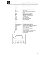
Drive Pulley:6 inch circumference
5 revolutions of motor travel results in 152.4 mm of linear road travel.This ratio
must be expressed as an integer to be used in the Gear Ratio command.Multiply
each side by 10 to get a Gear Ratio of 50 to 1524.
DIST = mm
RATIO = 50 to 1524
EDIT
SETUP MECH BKLASH
Backlash
- - Axis One Backlash ß 25.0 steps à
[BK]
Default:0.0 (Distance Units)
(Not yet implemented)
BKLASH allows your Smart Drive to compensate for the backlash in each axis of
your mechanical system.The Smart Drive will automatically take up (add) the
backlash distance specified whenever the move direction is reversed.
1. Use ß and à keys to select an axis.
2. Use the numeric keys to enter a backlash value in DIST units.
EDIT
SETUP MECH VEL
Velocity Units
[VU]
Default:rps (motor Revolutions Per Second)
- Axis One Vel. Units ßá mm/sec âà
Use this option to select your velocity units.All
velocity values specified in the system will be
expressed in these units.
1. Use ß and à keys to select an axis.
2. Use the áâ and ENTER keys to select velocity units from the list:
• rps
• rpm
• (DIST units)/sec (see DIST above)
• (DIST units)/min (see DIST above)
26
Chapter 4 - Configuring Your System
EDIT
SETUP MECH VMAX
Maximum Velocity
[MV]
Default:50 (velocity units)
- - Axis One Max Vel. ßá 50.0 inch/sec âà
This parameter limits the top speed of your motor. Depending on the application,
you may want to limit the speed of your control to prevent accidental damage to
your mechanics. For example,in a leadscrew driven system, exceeding the “critical
speed”will damage the leadscrew or ballscrew.
1. Use ß and à keys to select an axis.
2. Use the numeric keys to set the maximum velocity in VEL units.
EDIT
SETUP MECH ACCEL
Acceleration Units
[AU]
Default:sec
- Axis One Accel. Units
ßá
sec
âà
This option is used to select acceleration (and deceleration) units.All acceleration
and deceleration values specified in the system will be expressed in these units.
You can specify acceleration as a rate,or in time-to-accelerate to full speed.
1. Use ß and à keys to select an axis.
2. Use the áâ and ENTER keys to select acceleration units from the list:
• sec (time to reach top speed)
• (DIST units)/sec 2
• rps2 (motor Revolutions Per Sec 2)
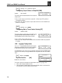
– Axis One Max Accel –
EDIT
> SETUP > MECH > AMAX
ß 0.002 sec à
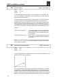
Configuring Acceleration Maximum [AM]
Default: 0.002 (acceleration units)
Range: 0.002 - 99999999 (acceleration units)
Acceleration maximum sets a maximum acceleration and deceleration limit for programmed move profiles in the cur rent acceleration units.Programmed accelerations and decelerations for moves will be limited by this parameter (analogous to
VMAX for velocity).Regardless of acceleration units,the absolute maximum acceleration is 0.002 seconds.
1. Use the ß and à keys to select an axis.
2. Use numeric keys to enter a new acceleration maximum in the same units
selected in the SETUP > MECH > ACCEL menu and press ENTER then ESC to
register.
27
B8961 and B8962 User Manual
I/O
Input & Output Configuration
Your IDeal ™ Programmable Smart Drive has eight discrete optically-isolated inputs,
and eight discrete optically-isolated outputs.It also supports up to eight Opto I/O
modules (G4/G5 footprint),which is like having a G4PB8 board and cable built in
— plus,it has the capability of supporting a mix of analog and digital modules.All
the inputs and outputs can be configured to a specific machine control function.
The eight OPTO positions can be inputs or outputs,logic or AC/DC power, digital
or analog,or even used as a thermocouple (Type K or J) inputs.The control is
completely protected from errors in interchanging modules.You will not damage
the unit by plugging in the wrong module.Simply insert the modules you need
into the positions you desire,and configure each position in the OPTO menu
(explained below) as either an input or an output.
Your IDeal Programmable Smart Drive is compatible with almost any manufacturer’s
G4 or G5 digital opto modules (OPTO 22,Grayhill,Gordos,etc.).However, at the
time of this printing,only Grayhill’s analog modules are compatible with our
control.Other manufacturer’s analog opto modules do not fit into a G4 footprint.
For more information on how to use your Smart Drive’s inputs and outputs in an
application, refer to Chapter 5, Applying the Product , and Chapter 6, Programming
Command Reference , in this manual.
The function of each input and output in your
system is easily configured in the I/O SETUP menus.
Once you have your I/O defined,it is a good idea to
write down your configuration scheme for later
reference when you develop your motion programs.
- - - â I/O SETUP á- - INPUT OUTPUT OPTOS
- - - â I/O SETUP á- - OUTSTS
LIMITS
OUTPUT STATES ON
OUTSTS (Output States on Event) allows user configPWR-UP FAULT ST/K
uration of output states after power-up, fault or a
Stop/Kill.LIMITS allows user configuration of the
EOT (End of Travel) switch polarity.Also a new configurable input CLR CMD
BUFFER “c”has been added.
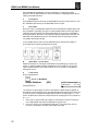
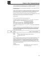
EDIT
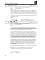
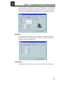
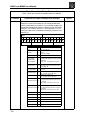
SETUP I/O INPUTS
Input Definition
[ID]
Default:UUUUUUUUUUUUUUUU
IN1: EXTEND JOG 1
EBBBKREJUUUUßáâà
The function of each input is easily configured using the keypad as described
below.
The function for each input channel is indicated by a letter along the bottom of
the display.The first 8 letters are for the dedicated Inputs and the last 8 letters are
for the optional OPTO inputs.
OPTO positions configured as outputs are shown as dashes and cannot be
configured without changing the position to an input in the OPTO menu.The
OPTO position’s default configurations are as inputs.(see below).
1.
2.
28
Use ß and à keys to select an Input.The function of the highlighted input
will be displayed on the top line.
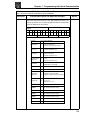
Once your cursor is on the desired input,use áâ to select from the following
list of dedicated functions for each input:
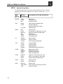
Chapter 4 - Configuring Your System
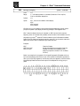
Character
B
C
c
D
E, e
F,f
H
I
J, j
K
M, m
N
P
R, r
S
U
V
W
Z
Function
Binary Formatted Program Select
BCD Formatted Program Select
Clear Command Buffer
Disable Keypad
Extend Jog, AXIS 1, axis 2
Set CL Force
Z axis home input
Interrupt (Run 98)
Jog Speed, AXIS 1, axis 2
Kill
Motor Shutdown AXIS 1, axis 2
Analog Input
Pause/Continue
Retract Jog, AXIS 1, axis 2
Stop
Unassigned
Data Valid
Warm Boot
Z Axis Fault
B
Binary Program Select Input
Allows programs to be run remotely using a PLC, switches or outputs from a
computer. Up to 199 programs may be selected using binary inputs.The lowest
numbered input becomes the least significant selection bit (i.e.,input #1 is less
significant than input #2).The act of configuring an input as a program select input
also enables binary program select mode.
C
BCD Program Select Input
Allows programs to be run remotely using a TM99 Thumbwheel module,PLC,
switches or outputs from a computer. Up to 99 programs may be selected using
BCD inputs.The lo west numbered input becomes the least significant selection bit
(i.e.,input #1 is less significant than input #2).
The act of configuring an input as a program select input also enables the BCD
program select mode.
c
Clear Command Buffer
Clears the terminal input buffer and buffered commmand buffer.
D
Disable Keypad
When activated,the keypad is disabled allowing NO user access.The keypad
resumes normal operation,subject to the dipswitch pattern,when the input is
released.
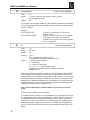
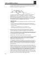
E, e
Extend Jog (E specifies AXIS 1, e specifies axis 2)
When activated,the motor will Jog in the Extend (+) direction.When the input is
released,motion stops at the Jog Accel rate.If an End of Travel limit is hit while
jogging,the motor will stop at the Stop Rate.(see Edit-Setup-Misc.) Before the
motor can be moved back off the limit,a Stop or Kill input must be activated to
clear the fault generated by hitting an End of Limit switch.Alternatively, an S or K
command sent over RS-232 will also clear the fault.
The velocity is determined by the Jog Speed Input and the Jog Low and High setup
parameters.When the input is off the speed is low, and vice versa.If none of the
inputs are configured for Jog Speed,the motor will jog at the Jog Low setting.
29
B8961 and B8962 User Manual
F,f
Set CL Force (F specifies axis 1, f specifies axis 2)
In addition to being able to set a clamping current via the CL command,the user
can also set the clamp curent on the fly based on an input.When the SET CL
FORCE input is asserted during a CL defined move,the control will maintain the
torque the motor is producing at that instant. For example,if the following move is
executing:VE1 CL3 DA3 GO (CL units are Amps),and a SET CL FORCE input is activated when the motor current control is at 1.5 amps,the current will be clamped
to 1.5 amps.If this input is not triggered,the control will clamp the current to 3
amps.The SET CL FORCE input requires a valid CL move to be in progress otherwise the input is ignored.The SET CL FORCE input is intended for applications
clamping to load cell feedback.
H
Z axis Home Input
Not yet implemented.
I
Interrupt (Run 98)
When activated,motion on all axes is stopped,at the stop-rate (see Edit-Setup-MiscStop-Rate).The current program is stopped,and processing continues with the first
command in program 98.If no program is running when the input is activated,
program 98 will run.This input is ignored while the keypad is in Edit mode.This is
a positive edge sensitive input, rather than a level sensitive input.If multiple inputs
are configured as Interrupts,only the first edge of the first activated input will be
seen.If subsequent Interrupt inputs go active while the first Interrupt input is
active,no additional interrupts will be seen.
Advanced Interrupt handling can be achie ved using the (INT98CRTL) and (ARM
INT98) variables.The (INT98CTRL) varia ble determines whether Inter rupts can be
disabed or not.The (ARM INT98) variable allows you to arm and disarm the
Interrupt as desired.
When the Indexer powers up (INT98CTRL) is initialized to 0.In this mode, evry
interrupt results in an immediate jump to program 98, even if you just entered program 98.This means that it is possible for the interrupt service routine to be interrrupted by another interrupt input.This functionality is backwards compatible with
earlier versions of firmware in IDC SmartDrives.The value of (ARM INT98) is
ignored.
When (INT98CTRL) = 1 you can enable and disable Interrupts at will with the
(ARM INT98) variable.Setting (INT98CTRL) = 1 also initializes (ARM INT98) to 1.
This means the control is watching for interrupts.When (INT98CTRL) is set to 1 an
interrupt causes the program to jump to program 98 AND sets (ARM INT98) = 0,
disabling any further interrupts until you reenable them by setting (ARM INT98) =
1.This allows you to control when you want to reenable interrupts in your interrupt service routine (program 98).
To summarize,when (INT98CTRL)=1:
If (ARM INT98) = 0
Interrupts are ignored. (ARM INT98) is automatically set to 0 by the Smart Drive on
the first edge of the input, if the previous (ARM INT98) value was 1. Interrupt processing will be suspended until (ARM INT98) is reset to 1.This allows for input debouncing and gives teh user control over the ability of program 98 to interrupt itself.
If (ARM INT98) = 1
The system is awaiting the firt INT98 input assert edge.Once the interrupt is seen
the control will go to program 98.Subsequent interrupts are ignored until (ARM
INT98) is set to 1.
30
Chapter 4 - Configuring Your System
(INT98CTRL) and (ARM INT98) are reset to default values on power-up.
Note: There is a space in (ARM INT98).
J
Jog Speed (J specifies AXIS 1, j specifies axis 2)
This input works along with the Extend Jog and Retract Jog.When a jog input is
activated the control checks the state of this input to determine the jog speed.If
the input is OFF, the system will jog at the Jog Low speed.If it is ON it will jog at
the Jog High speed.If the input is not configured the jog inputs will result in
motion at the low speed.
K
Kill Motion
When activated,causes the control to abruptly stop commanding further motion
and terminates program execution.No deceleration ramp is used.Caution should
be used because of the damage instantaneous deceleration could cause to your
mechanical system.The Stop input provides a more controlled halt.(Implemented
in V2.22 or later)
M, m Motor Shutdown: (M specifies axis 1, m specifies axis 2)
This input,only active at the top menu level,while a program is not running,
disables the motor.All current on the motor will be removed, resulting in little or
no holding torque.
N
aNalog
Only the OPTO I/O may be configured as analog inputs.To use an analog or
temperature I/O module the I/O position must be configured as an analog input
signal.This tells the Smart Drive that the input is no longer a discrete input and
prevents the input signal from being misinterpreted.
Analog signals are read into input variables (AI9) through (AI16) cor responding to
OPTO positions 9 through 16.See Programming Your Application for details on
using analog I/O.
P
Pause/Continue
While this input is grounded program execution is stopped.Moves are not
interrupted when the Pause input goes active.Command execution will Pause at
the end of the move,and Continue when the input goes high.See the ST command
for interrupting moves in progress.
R, r
Retract Jog (R specifies axis 1, r specifies axis 2)
When activated,the motor will Jog in the Retract (-) direction.When the input is
released,motion stops at the Jog Accel rate.If an End of Travel limit is hit while
jogging,the motor will stop at the Stop Rate.(see Edit-Setup-Misc.) Before the
motor can be moved back off the limit,a Stop or Kill input must be activated to
clear the fault generated by hitting an End of Limit switch.Alternatively, an S or K
command sent over RS-232 will also clear the fault.
The velocity is determined by the Jog Speed Input and the Jog Low and High setup
parameters.When the input is off the speed is low, and vice versa.If none of the
inputs are configured for Jog Speed,the motor will jog at the Jog low setting.
S
Stop
When activated,any program execution or functional operation is immediately
stopped.This includes any motion,time delays,loops,and faults.Moves will be
decelerated at the stop deceleration rate.New programs will not execute until the
stop input goes inactive.
31
B8961 and B8962 User Manual
See the SCAN setup parameter for more information on stopping program
execution.See the ST command for more information on stopping moves without
halting command execution.
U
Unassigned
An Unassigned input functions as a programmable input,and can be used in IF and
WT statements just like any of the dedicated function inputs.
V
Data Valid
When the input is configured,it determines if the Binary/BCD program select lines
are processed or ignored.If the input is active,program select lines are processed,
otherwise they are ignored.This allows applications to be wired in a pseudo-bus
architecture fashion with each unit sharing the same program select lines,and the
data valid inputs determining which units should listen.Configuring this output
can greatly reduce panel wiring.
In the example shown below, use the Data Valid input reduced the number of
wires required for selecting programs by one-half.
W
Warm Boot - System Reset
Resets the Smart Drive, clearing the RAM Buffer, and resetting the control to its
power up state.Programs and setup parameters are not erased.This is typically
used to restart system when a fault condition occurs.The power up program,if
defined,will be run.
Z
Z Axis Fault
Not yet implemented.
EDIT
SETUP I/O OUTPUTS
Output Definition
[OD]
OUT1: Programmable
PPPPPPPP - - - - ßáâà
Default:PPPPPPPP - - - - - - - The function for each output channel is indicated by a letter along the bottom of
the display.The first 8 letters are for the dedicated Outputs and the last 8 letters are
for Opto channels configured as outputs.Opto positions configured as inputs are
shown as dashes and cannot be configured without changing the OPTO position to
an output.
1. Use ß and à keys to select an Output or Opto output channel.The function
of the highlighted output will be displayed on the top line.
2. Once your cursor is on the desired output,use áâ to select from a list of
function configurations for each channel.See next page.
32
Chapter 4 - Configuring Your System
Character
A
B, b
C
D, d
F
H, h
I
K,k
L
M, m
N
P
S
T
U
Z
Function
Amplifier Fault
Brake
over Current
Direction
Fault
at Home
Indexer Step (Z axis)
At CL Limit
Limit Error
Move Complete
Analog Output
Programmable
Stall
Torque Mode
Unstable
Z Direction
A
Amplifier Fault
Output goes low on any amplifier fault.An amplifier fault may be due to
temperature,motor short circuits, excessive following error, over-voltage and
excessive regeneration conditions.
B, b
Brake (B specifies AXIS 1,b specifies axis 2)
It is often advisable that applications using a ballscrew type actuator with a vertical
load use a brake to prevent the load from falling in the event of a fault.Brake
outputs will go on whene ver a fault occurs and prevent a load from moving.
C
Over Current / Over Voltage Fault
Not yet implemented.
D, d
Direction (D specifies axis 1,d specifies axis 2)
The Direction Output indicates the direction of motion for a given axis.The output
remains set until motion begins in the reverse direction.
F
Fault
The fault output acts as a fail-safe fault output.Under normal operation the output
is grounded (ON) and goes high (OFF) when any type of fault occurs.(Smart Drive
software prior to V2.10 had this polarity reversed.) A fault can occur from any
amplifier fault condition as well as for the following general faults:
• BMA (Board Monitor Alarm) time-out.
• Error finding Home.Both limits were hit.
The exact cause of the fault can be determined in a number of ways:
• Shown on the keypad’s display.
• Over RS232 using the SS, SD, and SA status commands.
• Other outputs can be configured to show more specific fault states.
H, h
At Home (H specifies AXIS 1,h specifies axis 2)
The output is on as long as an axis is at home.
I
Indexer Step
Not yet implemented.
L
Limit Error
The output goes low if a limit switch is hit during a normal move,or if both limits
are hit during a Go Home move.
33
B8961 and B8962 User Manual
K,k
At CL Limit (K specifies axis 1, k specifies axis 2)
The AT CL LIMIT output will become active when the motor current reaches the
value defined by CL in the user’s program.This output allows the Servo SmartDrive
to indicate to a PLC when it has begun clamping,so that the user may synchronize
the clamping operation with other processes in the application (for example
drilling,cutting,or milling the clamped part).
M, m Move Complete (M specifies axis 1,m specifies axis 2)
The output goes high as soon as an axis move is started and goes low when a
move is completed.
N
aNalog
Only the OPTO I/O may be configured as analog outputs.To use an analog output
module the position must be configured as an analog output.This tells the Smart
Drive that the output is no longer a discrete output and assures that the output
signal is sent properly.
Analog signals are set by assigning a value to reserved variables (AO9)-(AO16)
corresponding to OPTPO positions 9 through 16.See Programming Your
Application for more details on using analog I/O modules.
P
Programmable
Unassigned outputs default to programmable and can be used in OT commands.
EDIT
S Stall
The output goes low if the control
detects a motor stall.
SETUP I/O OPTOS
Opto Configuration
Default:IIIIIIII
[OP]
OPTO14: Output
IIIIOOOO
ßáâà
T
Torque Mode
Not yet implemented.
U
Amplifier Unstable
Not yet implemented.
Z
Z Direction
Not yet implemented.
The OPTOS menu allows you to configure each OPTO I/O position as either an
input or an output.The hardware is protected against dama ge if you mistakenly
configure an input as an output.
Use the ß and à keys to select an OPTO channel.The top line displays
whether the channel is cur rently configured as an input or an output.
2. Once your cursor is on the desired channel,use áâ to select INPUT or
OUTPUT.
Your IDeal ™ Programmable Smart Drive is compatible with almost any manufacturer’s
G4 or G5 digital OPTO modules (OPTO-22,Grayhill,Gordos,etc.).However, at the
time of this printing only Grayhill’s analog modules are compatible with our
control.Other manufacturer’s analog modules do not fit into a G4 footprint.
1.
IDC stocks the following Opto modules,which may be specified when ordering an
IDeal ™ Programmable Smart Drive:
34
Chapter 4 - Configuring Your System
Order Code
(p/n)
A (PCB-1210)
B (PCB-1211)
C (PCB-1212)
D (PCB-1213)
E (PCB-1214)
F (PCB-1215)
G (PCB-1216)
H (PCB-1217)
I (PCB-1218)
J (PCB-1219)
K (PCB-1220)
L (PCB-1221)
M (PCB-1222)
N (PCB-1223)
Opto-22
Grayhill P/N
P/N
10-32 VAC/VDC Input
G4IDC5
TTL Input
G4IDC5K
35-60V DC Input
G4IDC5G
90-140 VAC Input
G4IAC5
180-240 VAC Input
G4IAC5A
5-60 VDC, 3 Amps Output
G4ODC5
12-140 VAC, 3 Amps Output G4OAC5
Output 24-280 VAC, 3 Amps G4OAC5A
Input Test Switch
G4SWIN
0-10 Volt Analog Input
73G-IV10
4-20 mA Analog Input
73G-II420
0-10 Volt Analog Output
73G-OV10
4-20 mA Analog Output
73G-OI420
J Type Thermocouple Input,
73G-ITCJ
0 to 700˚C
O (PCB-1319)
K Thermocouple Input,
-100 to 924˚C
P (PCB-1224)
RTD Thermocouple Input,
73G-ITR100
100 Ohm
More information on available OPTO modules is available from the Opto module
manufacturer or your local distributor.
EDIT
I/O Module Description
> SETUP > I/O > OUTSTS > PWR-UP
Configuring Ouput States on Power Up [OEP]
Default:
OFF
- On PwrUp Output #1 ßâ
This option.sets the desired states of the outputs on
power up.
OFF
áà
1.Use ß and à keys to scroll throu outputs #1 – #8 and any OPTO positions
configured as outputs.
2.Use the á and â keys to set the output state as OFF or ON and press ESC
to register.
EDIT
> SETUP > I/O > OUTSTS > FAULT
Configuring Ouput States on Fault [OEF]
Default:
NO CHANGE
- On Fault Output #1 ßâ
NO CHANGE
áà
This option.sets the desired states of the outputs on a
fault.
1.Use ß and à keys to scroll throu outputs #1 – #8 and any OPTO positions
configured as outputs.
2.Use the á and â keys to set the output state as OFF, ON or NO CHANGE and
press ESC to register.
35
B8961 and B8962 User Manual
EDIT
> SETUP > I/O > OUTSTS > ST / K
Configuring Ouput States on Stop/Kill [OES]
Default:
- On ST / K Output #1 -
NO CHANGE
ßâ
NO CHANGE
áà
This option.sets the desired states of the outputs on
a Stop or Kill.
1.Use ß and à keys to scroll throu outputs #1 – #8 and any OPTO positions
configured as outputs.
2.Use the á and â keys to set the output state as OFF, ON or NO CHANGE and
press ESC to register.
EDIT
> SETUP > I/O > LIMITS
Configuring End of Travel Switch Polarity [ET]
Default:
NORM CLOSED
This option.allows configuration of the EOT switch
polarity as NORM OPEN or NORM CLOSED to
accommodate the use of either type of switch.
-- Axis One EOT Pol -ßâ NORM CLOSED áà
1.Use ß and à keys to select an axis.
2.Use the á and â keys to select NORM OPEN or NORM CLOSED and press ESC
to register.
JOG
Jogging Configuration
Your IDeal ™ Programmable Smart Drive’s keypad
gives the programmer (and the machine operator
if desired) a convenient way to jog the motor.
- - - á JOG SETUP â - - ACCEL LO-VEL HI-VEL
The parameters which control your jog operation are set using the JOG SETUP menu:
Note:The Units used by the Jog parameters are configured from the SETUP-MECH
menu.
EDIT
- - - á JOG SETUP â - - ENABLE
SETUP JOG ACCEL
Jog Acceleration
Default:0.3 (Accel Units)
[JA]
- - Axis One Jog Accel
ß
O.3 sec
à
This option sets the acceleration and deceleration used during a jog move.
1. Use ß and à keys to select an axis.
2. Use the numeric keys to enter a new jog accel/decel value in the same units
you selected in the SETUP/MECH/ACCEL menu.
36
Chapter 4 - Configuring Your System
EDIT
SETUP JOG LO-VEL
Jog Low Velocity
[JL]
- Axis One Jog Lo-Vel
ß
O.5 in/sec
à
Default:0.5 (Velocity Units)
This option sets the low speed jog velocity used during a jog move.
1. Use ß and à keys to select an axis.
2. Use the numeric keys to enter a new low jog velocity value in the same units
you selected in the SETUP/MECH/VEL menu.
EDIT
SETUP JOG HI-VEL
Jog High Velocity
[JH]
Axis One Jog Hi-Vel
ß
2.0 in/sec
à
Default:2.0 (Velocity Units)
This option sets the high speed jog velocity used during a jog move.
1. Use ß and à keys to select an axis.
2. Use the numeric keys to enter a new high jog velocity value in the same units
you selected in the SETUP/MECH/VEL menu.
EDIT
SETUP JOG ENABLE
Jog Enable
[JE]
- Axis One Jog Enable
ß
ENABLED
à
Default:Enabled
This option enables or disables the jogging features
of the control.When disabled,an error message is displayed when the jog buttons
are pressed. Jogging functions are often disabled once a machine is installed to prevent operators from accessing them.
1. Use ß and à keys to select an axis.
2. Use á and â keys to enable and disable the function.
HOME
Homing Configuration
-- á HOME SETUP â MODE EDGE SWITCH
Your IDeal ™ Programmable Smart Drive has a built-in
homing function which combines the flexibility of a
customized homing routine with the ease of use of
calling a “canned”program.Also see the GH command
in the IDeal Command Reference chapter for more
details on homing.
EDIT
- á HOME SETUP â -OFFSET FINAL
> SETUP > HOME > MODE
Configuring Home Mode
[HM]
- Axis One Home Mode ßâ SWITCH ONLY áà
Default:
SWITCH ONLY (Any OPEN LOOP encoder mode)
SWITCH THEN Z (Any CLOSED LOOP encoder mode)
The homing mode parameter esta blishes how a Go Home (GH) command will
execute homing routines..
1.Use ß and à keys to select an axis..
2.Use the á and â keys to scroll through the list of homing modes and press
ESC to select..
37
B8961 and B8962 User Manual
Homing Mode
SWITCH ONLY
Description
GH will only home to the appropriate edge of the home switch
regardless of encoder mode.This is the only mode available without
an encoder.
SWITCH THEN Z
GH will home to the switch,align to the edge and then slowly move
until an encoder Z pulse is found.This mode requires an encoder.
Z CHANNEL ONLY
GH will slowly move until an encoder Z pulse is found.The state
of the home switch is ignored.The magnitude of the GH velocity
parameter is ignored.The sign of the GH velocity paramter determines the low speed direction.This mode requires an encoder.
EDIT
SETUP HOME EDGE
Home Edge
[HE]
- Axis One Home Edge ß
NEGATIVE
à
Default:NEGATIVE
This option selects which side (positive or negative) of the home switch active
region the Smart Drive must find before searching for the index channel of the
encoder.
1. Use ß and à keys to select an axis.
2. Use á and â keys to select the active edge as the positive or negative side of
the home switch.
EDIT
SETUP HOME SWITCH
Home Switch
[HS]
Axis One Home Switchß
Norm Open
à
Default:Normally Open
This option selects the type of switch used for the home input for each axis.A
Normally Open switch connects to ground when activated.A Normally Closed
switch is pulled high when activated.
1. Use ß and à keys to select an axis.
2. Use á and â keys to select the switch type.(NORM OPEN or NORM CLOSED)
EDIT
SETUP HOME OFFSET
Home Offset
[HO]
Default:0.0 (Distance Units)
- Axis One Home Offset
ß
0.0 rev
à
This option sets the home offset for each axis.After a successful homing move,the
home position (the default home position is +0.0000) is set to the offset value.
1. Use ß and à keys to select an axis.
2. Use the numeric keys to enter a new home offset value in DIST units.
A home offset allows you to have separate systems with identical programs in them.
All you have to change is the home offset value for each machine.It helps reduce
start up time,since your home limit switch can now be almost anywhere.It also
reduces the time necessary to get a system back up and running should your home
switch ever get damaged or moved.
Example:Home Offset = 1.0000
When the control finds the home position,it sets the position counter to
1.0000 distance unit.The absolute zero position counter is now referenced
1 unit behind the mechanical home position.All absolute moves will be
referenced from the absolute zero position.
38
Chapter 4 - Configuring Your System
EDIT
SETUP HOME FINAL
Home Final Direction
[HF]
- Axis One Final Dir. ß
POSITIVE
à
Default:POSITIVE
Specify the final approach direction of your Go Home (GH) move with this option.
This is the direction used to search for the encoder index mark (Z channel) after
the appropriate home switch edge is found.
1. Use ß and à keys to select an axis.
2. Use á and â keys to select the final approach direction.
PROG
Program-Run Configuration
- PROGRAM SETUP PWR-UP SCAN DELAY
Your IDeal ™ Programmable Smart Drive is capable
of running any pre-defined program on power-up,
or whenever a valid BCD or binary program combination is read on inputs
configured as BCD or Binary Program Select inputs (usually from a PLC or thumbwheel switches).The conditions under which these programs execute are defined
in PROGRAM SETUP.
EDIT
SETUP PROG PWR-UP
Power Up Program
[PU]
- - Power Up Program PROGRAM: 0
Range:n = 0 to 199 (0-400 w/ -30k option)
Default: 0
This option selects a power-up program.The selected program is executed (run)
when your Smart Drive is powered up or reset.If a value of 0 is entered in this
menu,or if the specified program does not exist,no program is run.
Use the numeric keys to enter a program number.
EDIT
SETUP PROG SCAN
Scan Conditions
[SN]
- - -Stop Scan After- - ßá YYYYYYY ESCâà
Default:YYYYYYY
The SCAN menu allows you to select which events will cause the control to stop
scanning program-select configured inputs.It is used to enable or disable stop-scan
events.If a given stop-scan event is enabled,the system will stop scanning the
inputs for program numbers when that condition occurs.The Smart Drive must be
reset via a Warm Boot input or by cycling power to start program scanning after an
active Stop Scan event.This option has no effect if the inputs have not been configured as program select inputs (either BCD or Binary).
1.
2.
Each event is represented by one of seven Y/N positions on the bottom display
line.Use ß and à keys to select a stop-scan condition.The selected event will
be listed to the right of these 7 characters:ESCape,STOP, LIMIT+,LIMIT-,KILL,
FAULT or INTerrupt.
Use á and â keys to enable (Y) or disable (N) the selected event.
39
B8961 and B8962 User Manual
EDIT
SETUP PROG DELAY
Scan Delay
[DY]
- - - Scan Debounce: - DELAY (ms): _
Default:100 ms
The DELAY time sets the amount of time the control requires the program select
inputs (BCD or Binary) to remain stable before the control will recognize and run a
program.The minimum time is 1 ms.If program select inputs are not stable for a
time equal to or greater than the specified delay, the program will not be executed.
Use numeric keys to enter a value in ms.
RS232
RS-232C Configuration
- - - RS232 SETUP - - ECHO UNIT #
If you plan to use the serial communications port on
your Smart Drive, you can use your keypad to turn the auto-echo on and off and set
the unit’s daisy chain address.The baud rate of 9600 is fixed on the Smart Drive.
Fixed RS-232 parameters:
• Baud rate:9600
• Data bits: 8
• Stop bits: 1
• Parity:none
EDIT
SETUP PROG ECHO
Echo Enable
[EC]
- - - - RS232 Echo - - - á
ENABLED
â
Default:ENABLED
This option is used to enable or disable the RS-232C echo.If the ECHO is disabled,
characters received by the control’s serial port will not be re-transmitted.ECHO
must be enabled in daisy chaining applications.
Use the áâ keys to enable or disable the ECHO.
EDIT
SETUP PROG UNIT#
Unit Number
- - - Unit Address - - NUMBER: _
[UN]
Default: 1
Range:(1-99) (Limited to 1-15 in firmware version 1.40 and earlier)
This option is used to set the unit address.Each unit in an RS-232C serial daisy
chain of multiple units must have a unique Unit Address.Refer to the section on
daisy chain operation in the RS-232 Operation chapter for more information on
this type of application.
Use the numeric keys to enter the unit address.
MISC
Miscellaneous Configuration Parameters
The following miscellaneous set-up parameters
include auto-formatting of the keypad display, setting
the deceleration rate used with a stop input,or the
ESC key while an axis is moving,and disable/enable
the TEST menus accessible from the RUN function
key.
40
- -á MISC SETUP â- DISP STOP-RATE TEST
- -á MISC SETUP â- FAULT ENABLE PASWRD
Chapter 4 - Configuring Your System
EDIT
> SETUP > MISC > DISP
DISP
< Quad #1 >Quad #2
Quad #3 Quad #4
[DF]
Default: Quad #1: POS1.
----Quad #1 Display ---Quad #2:POS2 (dual axis units)
á
INPUTS
â
BLANK (single axis units)
Quad #3:INPUTS
Quad #4:OUTPUTS
Display format allows teh user to customize the data displayed on the keypad run
time screen.The run time screen has been divided into 4,10 character configurable
quadrants.The DISP menu displays labels for teh 4 quadrants with carets (<>)
denoting the selected quadrant.
1. Use the ß,à, á and â keys to move quadrant selection delimiters (<>)..
2. Press ENTER to edit quadrant.
Once a quadrant is selected,there are 16 possible data types that can be displayed
in that quadrant.
Data Type
Quadrant Display
BLANK
No display
POS1
Axis #1 position
POS2
Axis #2 position
POS1+UNIT
Axis #1 position with axis units
POS2+UNIT
Axis #2 position with axis units
VEL1
Axis #1 commanded velocity
VEL2
Axis #2 commanded velocity
CUR1
CUR2
INPUTS
Axis #1 current in Amps (B896X only)
Axis #2 current in Amps (B896X only)
Discreet input status (0 of f, 1 on)
OUTPUTS
Discreet output status (0 of f, 1 on)
OPTOS
OPTO input and output status (0 off, 1 on) as configured
SA_STATUS1
Displays SA serial command response for axis #1
SA_STATUS2
Displays SA serial command response for axis #2
SS_STATUS
Displays SS serial command response
TEXT
Display user defined text in a quadrant
3.
4.
Use the á and â key to scroll through the data types and press ESC to register
all data types except TEXT (see below).
In order to define a text field,scroll to the TEXT data type and then press the
ALPHA key or a number key.A cursor will appear allowing up to 10 characters
to be entered.Type the desired text,press the ENTER key and then press ESC
to register.
EDIT
SETUP MISC STOP-RATE
Stop Decel Rate
[SR]
- Axis One Stop Decel
ß
0.1 (rps 2)
à
Default:100 rps2 (units fixed at motor rps2)
This option is used to set the deceleration rate for each axis whenever configurable
stop input is activated,or when the ESC key is pressed while an axis is moving.
41
B8961 and B8962 User Manual
This is usually set to the fastest controllable deceleration rate possible with
mechanics in your application.
1. Use the ßà keys to select an axis.
2. Use the numeric keys to enter a stop deceleration.
EDIT
SETUP MISC
TEST
n/a
Option currently not
implemented
Default:Enabled
Will be implemented in a future software release.
Enables and disables the RUN-TEST menu.Disable the test menu to prevent
operators from accessing test functions such as I/O operation,trace mode and test
moves.
Use the áâ keys to change the setting.
EDIT
> SETUP > MISC > PASWRD
CONFIGURING KEY PASSWORDS
[PW]
--- PASSWORD SETUP --OPRATR ADMIN CLEAR
Default:None
In addition to the keypad dip switches,user definable passwords allow restricted access to the RUN, EDIT, COPY and DEL menus.
1. From the PASWORD SETUP menu,press F1 to enter an OPRATR password or
press F2 to enter an ADMIN password.
2.Enter password using a maximum of 4 alpha-numeric characters only (0-9,A-Z
and a-z only).See S696X,B896X and 96X manuals on how to enter alpha-numeric data on the keypad.
3.Press ENTER to register the password and ESC to exit.
Defined Passwords
Menu Accessibility
ORATR only
ADMIN only
RUN, EDIT, COPY, DEL
RUN, EDIT, COPY, DEL
OPRATR with ADMIN
RUN only (All RUN functions except TEST)
ADMIN with OPRATR
RUN, EDIT, COPY, DEL
If no passwords are defined,there are no menu
Enter Password:
restrictions.If passwords are defined,pressing RUN,
>
EDIT, COPY or DEL will display the password
prompt.Entering the wrong password or pressing ESC at the password prompt
will return the keypad to the standard run-time display. Selecting EDIT > SETUP >
MISC > PASWRD > CLEAR will delete all passwords.
NOTE: Once a valid password is entered,the passPassword
word prompt is replaced by the USE LAST, RESET
USE LAST
RESET
prompt.Select USE LAST (F1) to use the last entered
password or RESET (F3) to require the password to be reentered (i.e. require the
next user to enter the password).This allows for subsequent use of the RUN, EDIT,
COPY and DEL keys without requiring the password to be entered each time.
42
Chapter 4 - Configuring Your System
Tuning Your Servo System
Your B8961 or B8962 IDeal ™ Programmable Smart Drive is a high-performance
servo drive and motion controller in a single package.Your entire servo “system”
includes the Smart Drive,motor and encoder.The encoder provides motor position
and velocity feedback to the Smart Drive.You create a motion program using the
IDeal programming language.The Smart Drive generates move trajectories and
motor torque based on your high-level commands,which tell the motor where to
go.It also takes care of closing the servo loops,which force the motor to follow
the velocity and position profiles.
Since the B Series Smart Drive is a fully digital drive,motor data must be
downloaded to it prior to operation.When an IDC MOTOR TYPE is selected from
the EDIT/SETUP menu in the Keypad or Application Developer, motor data and
tuning parameters are downloaded from the controller’s non-volatile memory, to
the drive’s on-board memory.This data includes motor winding information,pole
count,and encoder resolution.These files also contain default tuning parameters.
The tuning parameters have been optimized for use with IDC motors and
actuators.They work very well with inertia ratios up to about 15 to 1.Most
applications,in fact over 80%, require NO ADDITIONAL TUNING.
The B Series Smart Drives also allow you to monitor the performance of the drive
during machine integration.Each axis has an analog Monitor Port that can be
configured to output position and velocity error, as well as commanded velocity,
commanded torque,and actual torque,in real time,scaled to user defined units.The
Monitor Ports,along with an oscilloscope,make a powerful diagnostic tool.The
Monitor Port is a 12 bit analog signal,updated at 2 kHz.
IDC’s DSP-based servo Smart Drives use an easy-to-understand digital servo
algorithm,so tuning is straightforward.You also have the option of invoking two
additional proprietary algorithms,Anti-Hunt and Inertial Anti-Windup which may
further improve your system’s performance.
Your Smart Drive can be completely tuned with just the keypad and an
oscilloscope.(Even the oscilloscope is optional for less demanding applications.)
The keypad has two built in tuning functions.The first configures and scales the
monitor output port.This allows you to view, on an oscilloscope, real time velocity
and position error. No more “guessing”at the best tuning values.The second
function outputs a torque, velocity, or position command square wave to the motor
and mechanics.This extremely demanding move profile makes it easy to determine,
and minimize, overshoot and response time.
Compensator
43
B8961 and B8962 User Manual
Before starting the tuning procedure,it is important to have a general idea of the
control loop that you will be modifying.The structure of the B8000 control loop is
very simple.The loops are nested similar to a traditional analog servo system.
Because of this structure,the basic procedure for tuning a B Series Smart Drive is
generally non-iterative.A simplified schematic of the proportional - integral - velocity loop (PIV) compensator is shown below.The compensator also contains velocity
and acceleration feedforward terms that are not shown.
If tuning is needed for your application,it is a straightforward process.Please note
that an oscilloscope is required to do any more than the roughest tuning.If an
oscilloscope is not available,it is unlikely, except in very high inertia mismatch
applications,that modifying the default tuning parameters will result in increased
performance.
Tuning your system is a simple 3 step process.Each servo loop, velocity, position
and integral, must be tuned.Because of the implementation of the B8000 digital
servo algorithm this tuning process is non-iterative.The loops are tuned from the
inside out.The torque loop is motor/bus voltage dependent and is tuned at the
factory.
1. Tune the velocity loop using a velocity toggle.
2. Tune the position loop using a position toggle.
3. Tune the integral loop using a position toggle (optional)
Details on how to do this are covered below and,in much greater detail,in the
Servo Tuner manual.IDC also recommends accessing Servo Tuner’s on-line help
utility for the most up-to-date tuning procedures and hints.
RS-232C Users
- - - - - TUNING - - - - Servo Tuner users will find that the Servo Tuner manAXIS1 AXIS2 RS232
ual presents much of the same tuning information
that is in this section.Please reference Chapter 7 for
details on configuring a Smart Drive for RS-232 tuning,and the Servo Tuner manual
included with this product for detailed tuning information and strategies.
Pressing the EDIT key followed by the TUNING function key produces a menu that
looks like this:
Selecting RS-232 allows you to ena ble servo tuning via the Servo Tuner software.
Servo Tuner also has an Select/Axis1 or Axis 2 pulldown menu to access Smar t
Drives without keypads.We provide this menu option to keypad users because
there are additional tuning aids available with our Windows-compatible Servo
Tuner software.
44
Chapter 4 - Configuring Your System
Key Pad Tuning
The Keypad tuning utilities were designed to mimic most of the capabilities of
IDC’s Servo Tuner software,but in a menu structure format.The default gain
parameters generally provide adequate performance.If your application requires
exceptional performance,whether it be low velocity ripple, fast settling times,or
no steady state position error, you will may need to modify these standard gain
parameters.
The keypad menu tree is shown below. Explanations on the use of the TORQUE,
VELOCITY, and POSITION toggles can be found in the Servo Tuner manual.The
same basic strategies presented there,apply to keypad based products as well.
Keypad Tuning Menu Tree
GAINS
Axis SubMenus
Set-up
Description of Set-up Parameters
Parameters
GAINS
KV
KP
KI
KFA
KFV
Velocity Gain
Position Gain
Integral Gain
Feed Forward Acceleration Gain
Feed Forward Velocity Gain
TOGGLE
TORQUE
VELOCITY
POSITION
Torque toggle (magnitude and period)
Velocity toggle (magnitude and period)
Position toggle (magnitude and period)
MONITOR
MODE
RANGE
Configures monitor output function
Scales output function
NOHUNT
WINDUP
ON/OFF
ON/OFF
Anti-hunt proprietary servo algorithm
Anti-Inertial windup proprietary servo algorithm
Setting the Servo Gains
EDIT
á
KV=1537
< KV >
KP
â
KI
TUNING AXIS GAINS
á
KFA=0
â
< KFA > KFV
There are five user accessible servo GAINS, available
to tune your system.The gains are described below.
1. Use an F1,F2,or F3 to highlight the gain you wish to change.
2. Use the áâ keys to switch to the other menu.
3. Use the numeric keys to Enter a new value for the gain that is highlighted.
If you need to tune your system,the fastest way to get top performance out of it is
to tune it from “scratch.” Set all your gains to zero,and follow the procedure
outlined above,or in the Servo Tuner manual.
CAUTION: This procedure does not work on load with steady
state forces (such as gravity in a vertically oriented application).
Call IDC for details on tuning these difficult loads.
45
B8961 and B8962 User Manual
Toggle
Tuning Stimulus
EDIT
TUNING AXIS TOGGLE
POS
|0
|0
MODE | STEP | MSEC
1.
2.
Pick type of toggle;Press F1 to select a velocity, position,or torque toggle.
Magnitude of toggle.Press F2
• Torque:% of max torque
• Velocity:RPM
• Position:steps (8000 steps/rev)
3. Period of toggle (in msec).Press F3
4. Start toggle.
Your motor and system will start moving when you press the RUN key.The toggle
is stopped with the STOP (ESC) key.You can disable the amplifier by pressing the
DEL key. Pressing DEL a 2 nd time will enable the amplifier. If your system goes
unstable because of too aggressive a toggle,or because of improper gain settings,
disabling the amplifier is the only way to stop the out of control oscillations. Just
pressing the ESC key and stopping the toggle won’t stop an unstable system.These
same toggle “hot”keys are active in the GAIN sub-menu so tuning changes can be
made and evaluated while the system is actually moving.
CAUTION: The toggle generates instantaneous torque, velocity,
and position commands. The amplifier and motor will not be
damaged, but your mechanics may be damaged by these very
aggressive moves.
Monitor
EDIT
Monitor Port
TUNING AXIS TOGGLE
1.
2.
Press MODE (F1)
-----EDIT MONITOR----Pick parameter to monitor with the á and â
MODE RANGE
buttons.Choices include actual velocity,
commanded velocity, position error, and actual
torque.
3. Press RANGE.Enter the range of values you want to monitor.The units depend
on the parameter being monitored.
Connect your oscilloscope to Mon 1 (or Mon 2 for axis 2) and Mon Ref to view the
selected parameter.This output is updated at 2kHz anytime the Smart Drive is
powered up.Actual torque and velocity can be recorded while the program is
running and the axis are moving.
Anti-Hunt (NOHUNT) and Inertial Anti-Windup
(WINDUP) are two additional ser vo compensation
algorithms which you can utilize with your Smart
Drive.Details on these proprietary algorithms are
provided in the Servo Tuner manual.
46
-- á TUNING AXIS 1 â NOHUNT WINDUP
Chapter 5 - Programming Your Application
Programming Your Application
The purpose of this chapter is to provide information that will help programmers
begin developing applications with the SmartDrive.There are also several practical
examples that can be copied and modified.Other program examples are available
from the Application De veloper disk set (see DEMOS.idc).
Smart Drive Programming Overview
Before beginning to develop a machine control program with a SmartDrive,the
user must decide how the SmartDrive fits into the overall machine control hierarchy.There are three basic ways SmartDrives are used.They can be used in a standalone mode where the SmartDrive controls all the I/O and motion on a machine.
They can also be used with a PLC,where the PLC runs the machine and just calls
on the SmartDrive,via program select lines, for motion.Thirdly, they can be used in
a ìhostedî mode with a PC.In this mode no programs are stored in the SmartDrive,
the PC downloads a string of commands at execution time.
The information in this chapter applies to all three modes of machine control.The
SmartDrive uses a sequential,interpretive,command processor.This means that
commands in a program are executed one at a time,and that the action called for
in one command must complete before the next command is processed.
Example:[move] VE4 DI10 OT01 GO OT10
In the program [move],the maximum move velocity is set to 4,the command
incremental distance is set to 10,output 1 and output 2 are turned off and on
simultaneously, axis one then moves 10 units.After axis one stops moving,output 1
is turned on and output 2 is turned off.The state changes on outputs 1 and 2 happen at the same time.
The programmer can control the flow of the program with WT (wait for an event
or condition to occur),TD (wait for a pre-set amount of time to elapse),and IF (if a
certain condition is true at this instant,then execute a block of commands) statements.External controllers such as PLC and computers can be coordinated via digital outputs and ASCII strings sent out the serial port.
Creating or Editing Programs with the Keypad
IDC’s IDeal Command language is easy to remember and powerful.Command
descriptions are also available on-line using the HELP key within the Application
Developer program editor.
If you need help with basic keypad operation,please refer to Chapter 4 - Using the
Keypad , and Chapter 5 - Configuring Your System .
47
B8961 and B8962 User Manual
Command Summary
The chart below lists all the IDeal commands that can be stored and executed as a
part of a program.In Chapter 8, Programming with Serial Communication , there
is more information on serial commands,such as Setup,Immediate Status,
Supervisory Commands,and “Commands Not Available in Hosted Mode.”
Command Description
48
Command Description
AC
Acceleration
IV
Input Variable
BR
Break
LP
Loop
DA
Distance Absolute
LU
Loop Until
DC
Distance to a Change
LW
Loop While
DE
Deceleration
MC
Move Continuous
DI
Distance Incremental
MS
Message to Display
EA
Enable Amplifier
ON
On Command
EB
End of Block
OT
Output
EN
End of Routine
RG
Registration Move
FK
Function Key
SP
Set Position
GH
Go Home
SQ
Square Root
GI
Go Immediate
ST
Stop on Input
GO
Go (Start a Move)
TD
Time Delay
GP
Go Point
VE
Velocity
GS
Gosub
WT
Wait
GT
Go to
““
“Message to Serial Port”
IF
If Then
Chapter 5 - Programming Your Application
Variables and Arithmetic
Variables
The Smart Drive will accept a variable in a command instead of a constant.
Variables may be used in:
• Arithmetic
• Conditional Expressions
• Loop Counts
• Distance and velocity commands
• Set values
• Set command values or parameters
• Set analog signals
• Read analog or temperature input
• Display information such as position or velocity
• Any place that a number can be used,a variable can be used
Legal Variable Names
The Smart Drive allows you to create descriptive variable names,as opposed to V1,
V2,etc. Variables can be up to 14 characters,but the first 10 characters must be
unique.They can contain other printable ASCII characters,such as numbers,
underscores, exclamation points, even spaces.Upper and lower case characters are
supported within variable names,and these variable names are case sensitive.ASCII
control characters such as LF and CR are not supported.All variables must be
enclosed in parenthesis,(variable name). Parenthesis are not legal variable characters.
The standard software allows for up to 100 variables.All variables are stored as
fixed point numbers.All variables are global.All standard variables are volatile,
though non-volatile variables are available as well.
49
B8961 and B8962 User Manual
Built-In Variables
The following variable names are predefined in the control. They can be used
throughout your programs in expressions,to set voltages,to test conditions,or
even to display information on the keypad screen or some other external serial
device.
Variable Name
Description
(AI9) thru (AI16)
Analog Input 9 thru 16
(AO9) thru (AO16) Analog Output 9 thru 16
(AROWREL)
Read Only
Write Only
Read Only
(CPOS1), (CPOS2) Commanded Position of axis 1, 2
Read Only
(EPOS1), (EPOS2) Encoder Position of axis 1, 2
Read Only
(POS1), (POS2)
Current Position of axis 1, 2
Read Only
(VEL1), (VEL2)
Commanded Velocity of axis 1, 2
Read Only
(EE1) thru (EE20)
Non-volatile, limited use, user system
variables
Read/
Limited Write
Value of Function Key pressed
Read Only
Value of last Function key pressed
Read/Write
(TERM)
Sends variable out RS-232 port
Write Only
(1TW)
Scans inputs 1-4 for BCD Digit
Read Only
(2TW)
Scans inputs 1-8 for BCD Digit
Read Only
(TIME)
Elapsed Time (ms) since power up
or since reset
Read Only
(CRCS)
Value of the EEPROM setup checksum
Read Only
(CRCP)
Value of the EEPROM program checksum
Read Only
(SA1), (SA2)
Integer value of the status of axis 1-2
(See RS232 command SA)
Read Only
(SD1), (SD2)
Integer value of the drive status of axis 1-2
(See RS232 command SD)
Read Only
Integer value of the system status
(See RS232 command SS)
Read/Write
(INT98CTRL)
Enables/disables (ARM INT98) trigger
option - Refer to Ch. 5, Configuring Your
Inputs, Input Descriptions, Input I.
Read/Write
(ARM INT98)
Enables/disables INT98 input if
(INT98CTRL) is enabled
Read/Write
(FKEY)
(LASTKEY)
(SS)
50
Current status of any of the four arrow keys
Type
Chapter 5 - Programming Your System
Examples of Built-In Variables
•
•
•
•
•
(PIECES)=10
(SPEED)=(AI12)*(VEL SCALE)
MS21,“Enter Length”IV32,(LENGTH)
VE(SPEED)
MS1,(POS2)
• (TERM)=(POS1)
• (TEMPERATURE)=(AI9)
• (AO15)=4012
Assigns 10 to variable
Speed = analog input times a scalar
Prompts user and gets feed length
Sets velocity to value in variable
Displays current position of axis 2 on
keypad screen
Sends the current position of axis 1 out
the RS-232 port of the SmartDrive
Reads in temperature from analog input
Sets the analog output to 4012
Using the Built-In Variable (AROWREL)
(AROWREL) is a built-in Boolean read only variable which determines the status of
any of the 4 ar row keys. When used in conjunction with (FKEY),the user can
detect whether or not an arrow key is being held down. (AROWREL) will return
one of the following values:
(AROWREL) = 0 One of the arrow keys is being held down.
(AROWREL) = 1 The arrow key has been released.
(AROWREL) will return k ey status for the 4 arrow keys only. If any other key is
pressed,(AROWREL) will return zero regardless if the key is held down or not.The
following is an example jog application using (AROWREL) and (FKEY):
[MAIN]
{Program #1}
FK12,13{Wait for a Left or Right arrow key}
GT(FKEY)
{Jump to arrow key program #12 or #13}
[LEFTARROW] {Program #12}
MC+
{Enable MC mode}
AC.1
{Start MC move}
VE1
{Move in positive direction}
GO
LP
IF(AROWREL)=1{Check status of arrow key}
VE0 {Stop MC move on key release}
GO
GT1{Return to main program}
EB
EB
{End loop block}
[RIGHTARROW] {Program #13}
MC+
{Enable MC mode}
AC.1
{Start MC move}
VE-1
{Move in negative direction}
GO
LP
IF(AROWREL)=1{Check status of arrow key}
VE0 {Stop MC move on key release}
GO
GT1{Return to main program}
EB
EB
{End loop block}
51
B8961 and B8962 User Manual
Non-Volatile Variables
The non-volatile variables (EE1)-(EE20) are twenty user accessible variables that
retain their values through power cycles, warm boots,and system resets.Standard
user variables are reset at power down or reset.Each time one of these variables is
changed (i.e.used on the left side of an equal (=) sign,the new value is written to
and stored in the user non-volatile EEPROM.
CAUTION
Caution must be observed when using these variables. Since EE
have a limited read/write lifetime (100,000 writes before failure),
variable values that change frequently should not be stored as EE
system variables. Examples include loop-count variables, and
POS1 and POS 2 variables. The SmartDrive will allow only 1,000
EE writes between power cycles. This limit has been set to prevent a simple programming mistake or misunderstanding from
permanently damaging the SmartDrive’s non-volatile memory.
When this write limit has been exceeded, all programs will stop
running, an error message will be displayed, and the appropriate
status bits will be set.
The EE system variables were originally developed for use in batch manufacturing
applications where a number of variable setup parameters must be entered at the
start of each part run.These same setup parameters can then be used through any
number of power cycles,or machine resets.
Example:A program called [Set-up] is run at the start of each part run to initialize a
number of variable part parameters.During production the program called [PARTS]
is run.This program reads from the EE variables,but does not generate any writes
to the EE,so the lifetime of the EE is not compromised.
[Set-up]
MS1,”Feed length?:”
IV12,(LENGTH),1,15
MS1,”Feed Speed?:”
IV12,(SPEED),.05, 5
(EE1)=(LENGTH)
(EE2)=(SPEED)
EN
[PARTS]
(LENGTH)=(EE1)
(SPEED)=(EE2)
LP(NUMBER)
DI(LENGTH)
VE(SPEED)
GO
OT1 TD.1 OT0
EB
52
Writes string beginning at character 1,top line
Loads the part length into volatile user variable
(LENGTH)
Writes string beginning at character 1,top line
Loads the speed into volatile user variable (SPEED)
Loads the length into non-volatile system variable (EE1)
Loads the speed into non-volatile system variable (EE2)
[PARTS] runs on power up,unless new parameters
are entered.
Load the part specific variable from the non-volatile
variables.
Loop (NUMBER) of times
Move (LENGTH)
at (SPEED) velocity
Toggle output to indicate part done
End the loop Block
Chapter 5 - Programming Your Application
Arithmetic Operands and Equations
The SmartDrive supports addition (+),subtraction (-), multiplication (*),and division (/).Expressions may only contain one operand.Complex equations require
multiple statements. Variables and fixed point numbers may be mixed in arithmetic equations.All user arithmetic and variable storage uses 32-bit integer and
fractional representation.
The + and - symbols have a dedicated button on the keypad.Pressing the button
will toggle between the two.
The *,/,and = are accessed from the Alpha+0+... keystrokes.
Examples:
• (X)=(Y)*10
• (AO15)=(VOLTAGE)+(ERROR)
Do not enter:
• (X)=1+2-3
• (Length)=(Total)*.03125
Instead enter:
• (X)=1
(X)=(X)+2
(X)=(X)-3
or
or
This statement is not legal,because it has more
than one operand.
The Smart Drive fixed point variable storage only
supports 4 places to the right of the decimal place
(32 bit storage of fractional decimal number).
(X)+=2
(X)-=3
and
• (Length)=(Total)*3.125
• (Length)=(Length)*.01
• or (Length)=(Total)/32
Multiply by the significant figures.
Then move the decimal place.
The SmartDrive fixed point variable storage
supports 4 characters to the right of the
decimal place (32 bit storage of fractional
decimal number).
Boolean Operators - & (And), | (Or)
The operators & and | will perform the respective bitwise Boolean functions on
immediate or variable parameters.
An application example of the Boolean operators would be:isolating a specific bit
from an SD (Tell Drive Status) response.Suppose you want to determine if axis #1
drive was enabled from a program.This corresponds to a bit #5 (10000) Binary,
(16) integer in the SD response.The program segment would look as follows:
(DRIVE STAT)=(SD1)&16 IF(DRIVE STAT)=16 MS,1”Drive Enabled”EB
The 16 corresponds to an integer weight of bit #5 (10000) since you wish to
“mask”out the enable bit.
53
B8961 and B8962 User Manual
Logical Operations on Expressions (&&,||)
Conditional commands (IF,WT, LU, LW) support logical operations of AND (&&)
and OR (||).Two expressions may be logically AND’d or OR’d within one conditional command. For example:
(A)=5 (B)=2.5 IF(A)>2&&(B)=2.5 MS1, “True Statement” EB
In the above program,the message “True Statement” would appear since BOTH
conditional statements are true,thus making the entire IF conditional true.
AND
OR
Expression A Expression B
A&B
Expression A Expression B
A || B
False
False
False
False
False
False
False
True
False
False
True
True
True
False
False
True
False
True
True
True
True
True
True
True
Incrementing and Decrementing Variables (++, =+, --, -=)
There are four syntaxes supported by variables:++ (single increment),+= (value
increment),-- (single decrement),-= (value decrement).These operators will initialize any uninitialized variable to zero before incrementing or decrementing it for
the first time.
(Variable Name)++
(Variable Name)+=n
(Variable Name)-(Variable Name)-=n
Increments a variable value by 1
Increments a variable value by n
Decrements a variable value by 1
Decrements a variable value by n
Expressions
The SmartDrive supports five conditional expressions:less than (<),equal to (=),
greater than (>),less than or equal to (<=),and greater than or equal to (>=). The
IF and WT commands can use these expressions to direct program flow or wait for
an analog input to meet a condition.The > and < symbols are entered into the keypad editor with the ALPHA+↑+↑....↑
Examples:
IF (X)>10 GS20 EB
WT(AI12)<(MAX TEMP)
54
If X is greater than 10 gosub to program #20
Wait for the temperature to go below the maximum
before continuing command processing.
Chapter 5 - Programming Your Application
Summary of Operators, Functions and Expressions
[]
Name Program
()
Name Variable
&&
Logical AND
||
Logical OR
!
Logical NOT
!=
Not Equal
+
Add
-
Subtract
*
Multiply
/
Divide
=
Equal
>
Greater Than
<
Less Than
>=
Greater Than or Equal to
<=
Less Than or Equal to
&
Bitwise Boolean AND
|
Bitwise Boolean OR
++
Increment Variable
+=
Increment by n
--
Decrement Variable
-=
Decrement by n
<<
Shift Left
>>
Shift Right
Multi-axis Operation
IDC’s IDeal command language is intuitive, yet powerful enough for difficult applications.The SmartDrives allow you to make multi-axis,synchronized,moves or multiple independent moves that start at the same time.
Simple GO Commands
The most intuitive and simple prog rams utilize the GO commands.Motion parameters for each axis are separated by commas. Motion parameters consist of the AC,
DE,VE and either DI or DA command.These four parameters completely define the
commanded motion profile.The last parameter used by an axis is stored in a table.
The GO command uses the last DI or DA command processed to determine which
axes move and how far they move. For example:
55
B8961 and B8962 User Manual
AC2,5
VE10,3
DI9,-3.1
GO
Set acceleration of both axes
Set velocity of both
Set distance of each axis
Start both together
DI9
GO
Moves only axis 1 because the last D command
only had a parameter for axis 1
DI,2
GO
Moves only axis 2 because the last D command
only had a parameter for axis 2
In the first move in the example,the GO command is used to start multiple axes at
the same time.The move profiles for each axis are independent.While axes start at
the same time,the moves are independent and will follow their respective accelerations and velocities,though the axes may not stop moving at the same time.
The Go Point (GP) command allows you to move two axes along a linear path that
starts and stops at the same time.The control uses the most recent value in axis 1,
the first parameter, to specify the AC,VE,and DE values along the path (see example 1 below).In most cases, your program will be easier to understand if you redefine these parameters as a single value for the path (see example 2 below).GP uses
the last distance value for each axis to determine the end points of the linear
move.The two examples below result in identical GP moves.
Example 1:
AC2,3
VE4,10
DE.5
DI5,6
GP
Example 2:
AC2
VE4
DE.5
DI5,6
GP
GO and GI commands support additional parameters providing more advanced features.The additional parameters allow you to:
1.
2.
3.
4.
5.
Start each axis based on different conditions.
Start one axis with an input while another is moving.
Start one or more axis moving based on one input.
Start different axis based on different inputs.
Reduce the size of a program by using fewer “move”commands.
GO supports an extended syntax to allow these other move specifications.
GOi,i or GIi,i
i = 0-16,integers only
The extended syntax always explicitly defines which axes will move.Only those
axes which have an active input defined by i will move,and the last move parameters will define the shape and length of the move profile.
An axis will start moving when the input defined by i turns on. You can start different axes at dif ferent times by using different integers (i) for each axis.
Setting i = 0 will explicitly define which axis will move when a GO command is
processed.(See the examples below for more clarification.)
56
Chapter 5 - Programming Your Application
The last move parameters used to define a move profile are saved.This saves program space in applications where sections of code repeat the same moves.The DI
or DA command is the only motion parameter that needs to be repeated.A stairstep pattern is one example of this.
Using different i’s for each axis allows you to start one axis and wait for an input
on another, or start both based on different inputs.See the examples below for
more clarification.
Examples:
GO
DI3 GO
DI3,4 GO
DI2,2 GO,0
DA(Part 1),(Part 2)
GO4,5
GO4,4
Moves all the axes defined in the last DA
or DI command
Move only axis 1
Move axes 1 and 2
Move only axis 2, even if the last DA or DI
command defined both axes
Move axis 1 once input 4 is activated,
axis 2 once input 5 is activated
Move axis 1 and 2 once input 4 is activated
57
B8961 and B8962 User Manual
Typical Programming Examples
The following program examples will show how the IDeal command language can
be used to perform simple tasks.There are more extensive and elaborate example
programs in the DEMOS.idc file that came with your Application Developer disk
set.
To aid your program documentation,comments can be placed in brackets {comment}.These comments are stripped out of the program as it is downloaded to
help conserve memory in the control. Files should be saved BEFORE downloading
for documentation purposes.
Example: DI10,2 GO
DI15,15 GO
{Moves to load position}
{Moves to unload position}
To create a Message and input a Variable
[GET PARTS]
MS1,””
MS1,”How many?:”
IV12,(PIECES)
MS1,””
MS1,”How long?:”
IV12,(LENGTH)
LP(PIECES)
DI(LENGTH)
GO EB
{Name the subroutine}
Clears the display
Writes string beginning at character 1,top line
Waits at 12th character for the # of pieces
Clears the display
Writes string beginning at character 1,top line
Waits at 12th character for the length
Loops the number of pieces entered
Moves the length entered
Creating an Operator Menu (see the FK command description for details)
MS1,””
MS21,”PART1 PART2 PART3”
FK1,2,3
(FKEY)=(FKEY)+50
GT(FKEY)
Clears keypad screen
Writes a message above function keys
Waits for a Function Key to be pressed
Add an offset to FKEY
Goto program #51,52,or 53.(50 + 1,2,or 3)
Fast In, Slow Feed Move (Using the Distance to Change (DC) command)
AC.05
DE.09
VE50
DA6
DC5.5
VE5
GO
58
Set acceleration
Set deceleration
Set first velocity
Set total move distance
Set point where you want to change speed
Set second speed
Start the move profile
Chapter 5 - Programming Your Application
Turning On an Output on-the-fly
AC.05
VE10
DA4
DC1
OT1
DC2
OT2,1
DC3
OT3,1
GO
Set acceleration
Set velocity
Set total move distance
Set point to turn on...
Output 1
Set point to turn on...
Output 2
Set point to turn on...
Output 3
To input a 4 Digit BCD number reading 2 Digits at a time
[GET 4 BCDS]
OT01
(4 DIGIT BCD)=(2TW)*100
OT10
(4 DIGIT BCD)=(4 DIGIT BCD)+(2TW)
Returns value of 4 digit BCD number
Connect ground of first two BCD digits
Make value of first two digits the MSB
Connect ground of 2nd two BCD digits
Add value of 2nd two to 1st two * 100
Reading an Analog Input
The value of the analog system variables (AI9-16) are scaled from 14,400 to 72,000
Hz.This value is actually a scaled frequency read by the SmartDrive.These input
values are updated every 16 milliseconds .If your program needs to display this
value in units such as VOLTS, you will need to scale the value to VOLTS in your program.The scale number you use will depend on which analog input you are using.
For example:a "J" thermocouple uses a different factor than a "K" thermocouple.
Example:Using a 0-10 VDC analog input.0V=14,400;10V=72,000 or 5,760 Hz/volt.
(VOLT)=(AI12)
(VOLT)=(VOLT)-14400
(VOLT)=(VOLT)*1.736
(VOLT=(VOLT)*.0001
Read the value of analog input 12 into
variable volts
Remove frequency offset
Scaling factor multiplied by 10,000
Scaling back to volts
The variable (VOLT) is now in units of volts.If you are waiting for a condition to
occur or doing a comparison,(see below) there is no need to go through the conversion process.
(TEMP)=(AI9)
WT(AI12)<45000 GO
IF(AI12)<45000 GO EB
Read in temperature from analog input
Wait for analog input 12 <45000 (<5.3 VDC
using the previous example) before moving
Go if analog input 12 < 45000
59
B8961 and B8962 User Manual
Configuring an Analog Output
The analog outputs of SmartDrives are 12-bit outputs.The value of the analog output is scaled to this 12-bit (0-4095) resolution.If you have a 4-20 mA output you
will have an output resolution of .004 mA.
The output value is set with the system variable (AOn). n=9-16
The value of n corresponds to the OPTO position of the analog output.
To configure an OPTO position as an analog output:
1.
2.
Configure the position as an output using EDIT > SETUP > I/O > OPTOS.
Configure the output position as analog using EDIT > SETUP > I/O > OUTPUT.
The analog system output varia ble has a range of 0-4095 (12 bits).0 is the minimum output and 4095 is the maximum value of the analog module you are using.
Example:
4-20mA output module,0= 4mA,4095=20mA,
(AO15)=256
60
Sets the analog output to 5 mA
Chapter 6 - Programming Commands
Programming Commands
This chapter defines,in alphabetical order, all of IDC’s IDeal ™ commands that can
be used in a program.Please refer to Chapter 4, Using the K eypad, for more information on entering these commands with the keypad.
Some IDeal commands are supported only in serial communication mode.These
commands are listed and defined in Chapter 8, Programming with Serial
Communication , and they can also be found in the Summary of Commands
immediately inside the back cover of this manual.
The commands in this chapter are defined according to the following example:
DI
Distance Incremental
Units:
Range:
Default:
syntax - DI±r,±r
selected from the EDIT > SETUP > MECH menu (n/a if no units)
unit scaling dependent (n/a if no range)
If the command has a default,it will be listed here
(n/a if there is no default)
DI specifies a move distance relative to the current position.Such moves are called
incremental moves,as opposed to the absolute zero reference used in DA.
Incremental moves are typically used in applications where there is no concern for
origin,such as feed-to-length applications.Incremental moves are also often used
inside a loop to shorten a program.Incremental and absolute moves may be mixed
- the control always keeps track of the absolute position.
Example:
Move 2 units in the + (positive) direction.
Move 1 more unit in the + direction.
Move 4 units in the - (negative) direction.
Program:
AC.1 VE60 DI2 GO DI1 GO DI-4 GO
61
B8961 and B8962 User Manual
Summary of IDeal ™ Commands
62
Command
Description
AC
Acceleration
BR
Break
DA
Distance Absolute
DC
Distance to a Change
DE
Deceleration
DI
Distance Incremental
EA
Enable Amplifier
EB
End of Block
EN
End of Routine
FK
Function Key
GH
Go Home
GI
Go Immediate
GO
Go (Start a Move)
GP
Go Point
GS
Gosub
GT
Go To
IF
If Then
IV
Input Variable
LP
Loop
LU
Loop Until
LW
Loop While
MC
Move Continuous
MS
Message to Display
ON
On Command
OT
Output
“__”
“Message to Serial Port”
RG
Registration Move
SP
Set Position
SQ
Square Root
ST
Stop on Input
TD
Time Delay
VE
Velocity
WT
Wait
Chapter 6 - IDeal™ Command Reference
AC
Acceleration
Units:
Range:
Default:
syntax - ACr,r
sec,rps 2 or unit/s 2
(selected from the EDIT > SETUP > MECH menu)
unit scaling dependent
n/a
AC sets the acceleration and deceleration ramp on all velocity changes.The deceleration value (DE) will be the same as the acceleration value unless it is specifically
set after the AC command.The value of DE must be reset every time AC is changed.
Use only AC if you want a symmetrical move profile.Use DE if you want a different
deceleration rate.Subsequent moves will use the last DE or AC value specified.
Examples:
AC2VE12 DA3 GO
DE.5 VE12 DA6 GO
VE20 DA0 GO
AC4 DA2 GO
DE3 AC1 DI3 GO
BR
Sets acceleration and deceleration to 2.
Accel stays at 2,decel changes to 0.5.
Acceleration and deceleration remain at 2
and 0.5.
Acceleration and deceleration become 4.
DE reset to 1 by AC1 before the move is made.
Break
Units:
Range:
Default:
syntax - BR
selected from the EDIT > SETUP > MECH menu
unit scaling dependent
n/a
The Break command instantly “breaks”a loop block in which it is defined and continues program execution from the loop’s terminating EB command.This allows for
more complex loop conditioning than LU or LW commands.
Example:
(A)=0
(B)=0
LP
IF(A)>10
IF2,0
BR
EB
EB
(A)++
EB
MS1,”A is greater than 10”
{Define variable A}
{Define variable B}
{Define loop block}
{Check if A is greater than 10}
{Check if input #2 is off}
{Break loop}
{Increment variable A by 1}
{BR command jumps here}
{Display message}
63
B8961 and B8962 User Manual
DA
Distance Absolute
Units:
Range:
Default:
syntax - DA±r, ±r
selected from the EDIT > SETUP > MECH menu
unit scaling dependent
n/a
DA sets the next move position, referenced from absolute zero.The absolute zero
position is established after a Go Home move (GH) and/or with the Set Position
(SP) command.Absolute positioning is typically used in applications where you are
moving to a number of known locations,or if your physical work area is restricted.
Incremental (DI) and absolute moves may be mixed;the control always keeps track
of the absolute position.
Examples:
AC2 DE.5 VE12 DA3
DA3 GO DA3
DC
GO Moves to absolute position 3 units.
GO Moves once to absolute position 3 units.
Distance to a Change
Units:
Range:
Default:
syntax - DC±r, ±r
selected from the EDIT > SETUP > MECH menu
unit scaling dependent
n/a
DC is used to define a complex, multiple velocity move profile,or to change an
Output at a specific point during the move.It defines a position at which a change
will occur,“on the fly,” while the motor is still moving.At the specified position you
can change the velocity or change the state of one or more outputs.
The DC command must follow a DA or DI command which specifies the total
move distance.The DC distance is interpreted as an absolute position when used
with DA and an incremental position when used with DI.When used with DI,the
value of DC must be specified as a positive number.When multiple DC’s are specified within an incremental move (DI),the incremental distance specified by the DC
command is taken from the last DC command,not from the beginning of the
move.See the incremental move examples below for more clarification.The stan dar d software supports a maximum of 20 DC commands within a move profile.
Application Note: The DC command can only be used when the motor is
moving at constant speed, i.e. not accelerating or decelerating. Issuing a DC
command (or trigger position) before a previous DC has finished execution is
invalid and can cause unpredicta ble results. For example,the following programmed move profile is an incor rect use of the DC command: AC1 VE5 DA20
DC1.75 VE7.5 GO
Since the initial acceleration ramp requires 2.5 units of distance to reach velocity
, the DC1.75 is an invalid trigger position and will be ignored.
The following formula ensures the use of valid DC trigger positions:
64
Chapter 6 - IDeal™ Command Reference
Where n is the current DC command distance (n=19 in this example), n-1 is the
previous DC command distance (e.g.10), V is the velocity, and t is acceleration
time (for the first DC specified in a move profile, n-1 would correspond to the
beginning of the move).
In the following move profile,AC units = seconds,VE units = RPS (see illustration):
AC1.6 DE0.8 VE5 DA20 DC10 AC2.5 VE3 DC? VE2.5 GO
Using the DC formula and solving for DCn,
therefore,
the “?” must be greater than or equal to a position of 12.5 distance units.In addition
to verifying the DC trigger position,it must also be verified that the DC? VE2.5 segment can be completed before the beginning of the move deceleration.Suppose
the “?” was chosen to be 13.35 (a valid trigger position),use the beginning of the
decel ramp as the DC n in the DC formula.A deceleration from 2.5 to 0 requires 1
distance unit in 0.8 seconds
therefore,
the result is positive,the DC13.35 VE2.5 is a valid segment.
Since
Examples of DC move profiles:
AC.05 DE.05 VE10 DA4 DC1 OT100 DC2 OT010 DC3 OT001 GO
While moving to an absolute position of 4 units turn on output 1 at 1 unit,output
2 at 2 units and output 3 at 3 units.
AC.05 DE.09 VE30 DA6 DC3VE15 GO
Move to absolute position 6 units with a starting speed of 30.At 3 units, reduce
speed to 15 (change-on-fly) and complete move.
AC1 DE.5 VE20 DI-8 DC1 OT10 DC3 OT01 GO
Move an incremental distance of negativ e 8 units.After 1 unit,turn on output 1,
and after 3 additional units of motion,turn off output 1 and turn on output 2.
AC.05 DE.15 VE50 DI15 DC5VE10 DC5VE5 GO
At a starting speed of 50,begin moving an incremental distance of 15 units.After 5
units, ramp down to 10 speed.After an additional 5 distance units, ramp down to
5 speed and continue until the final position is reached.
AC.1,.1 VE10,20 DI10,10 DC5,5VE20,10 GO
Move an incremental distance of 10 units on axis 1 and 2.After 5 units on axis 1,
ramp up to a speed 20;after 5 units on axis 2, ramp down to speed 10.Note that
these velocity changes both take place after 5 distance units,but they do not take
place at the same time.
65
B8961 and B8962 User Manual
DE
Deceleration
Units:
Range:
Default:
syntax - DEr,r
sec,rps2 or unit/s2
unit scaling dependent
n/a
Sets the deceleration ramp on all negative velocity changes. The deceleration value
will be the same as the acceleration value unless a deceleration is specified.The
value set will be used on subsequent moves unless it is re-specified by either an
acceleration (AC) or deceleration (DE) command.
Examples:
AC2 VE12 DA3 GO
DE.5VE12 DA6 GO
VE20 DA0 GO
AC4 DA2 GO
DE3 AC1 DI3 GO
DI
Sets acceleration and deceleration to 2.
Accel stays at 2 and decel changes to 0.5.
Acceleration and deceleration remain at
2 and 0.5.
Both acceleration and deceleration become 4.
AC1 sets both the accel and decel to 1.
Distance Incremental
Units:
Range:
Default:
syntax - DI±r, ±r
selected from the EDIT > SETUP > MECH menu
unit scaling dependent
n/a
DI specifies a move distance relative to the current position.Such moves are called
incremental moves,as opposed to the absolute zero reference used in DA.
Incremental moves are typically used in applications where there is no concern for
origin,such as feed-to-length applications.Incremental moves are also often used
inside a loop to shorten a program.Incremental and absolute moves may be mixed
- the control always keeps track of the absolute position.
Example: AC.1 VE60 DI2 GO DI1 GO DI-4 GO
Move 2 units in the + direction.Move 1 more unit in the positive direction. Move 4
units in the negative direction.The final absolute position is -1.0000.
EA
Enable/Disable Amplifier
Units:
Range:
Default:
syntax - EAi,i
n/a
0 (disable),1 (enable),2 (standby)
n/a
EA sets the state of the amplifier enable signal.The polarity can be changed in EDIT
> SETUP > MISC > ENABLE.
Example:
66
EA0
Disables the amplifiers on axis one and two.
Chapter 6 - IDeal™ Command Reference
EB
End of Block
Units:
Range:
Default:
syntax - EB
n/a
n/a
n/a
The EB command designates the End of a Block of loop or IF commands.Every LP,
LW, LU, and IF statement must have an EB associated with it.
Examples:
LP2 DI3 GO EB
IF1,1 DI5 GO DI10 GO EB GH3
EN
End of Routine
Units:
Range:
Default:
Performs the move twice
If input 1 is On,make 2 moves before
homing. If input 1 is Off, jump to the GH
command.
syntax - EN
n/a
n/a
n/a
EN marks the end of a program or subroutine.It is optional at the end of a program.If EN marks the end of a subroutine,command execution continues from the
command following the gosub (GS) command which called the subroutine.If the
routine was not called from another program,the EN command simply stops command execution.The control continues to monitor the program select inputs (if
defined).
The EN command can be used anywhere in a program to stop command execution.
Example:
IF2,1 EN EB DI2 GO
FK
Function Key
Units:
Range:
Default:
If input #2 is on,stop the program,or return
to the calling program.If not,move 2 units.
syntax - FKi,i,...i
n/a
i = 1-28
n/a
Note:24,the ESC key, cannot be assigned since it stops a program.
The FK command allows you to redefine a keypad key function within your program.The FK command pauses processing until the buttons you have “armed”are
pressed.The number of the armed button is assigned to the system variable,
(FKEY).You can then manipulate or directly use this variable to branch to other
routines or make other decisions.FK allows the programmer to redefine the keypad function keys as operator menu selection buttons.You can even write your
program with menus that look and feel like our setup menus.
Example:
FK1,2,3,4
GS (FKEY)
Pauses command execution until F1,F2,F3,or RUN is
pressed on the keypad.(FKEY) is assigned a value of 1-4.
Subroutine 1-4 is called with the GS (gosub) command.
67
B8961 and B8962 User Manual
See the illustration below for the value of (FKEY) returned for each key:
The following example shows how to use the keypad function keys as an operator
interface:
1.
2.
3.
Write a menu messa ge (MS) on the keypad display above the corresponding
function keys.
Use the FK command to pause command processing until the operator selects
a valid function key. Only keys explicitly defined in the FK statement are considered valid.
Gosub to the appropriate prog ram.
Example of a 3-screen menu program:
Program 20:
[SCREEN 1]
MS1,””
MS3,”Select a Part”
MS21,”Part A Part B Part C”
FK1,2,3,17,18
GT(FKEY)
EN
Name the main program
Clears keypad screen
Writes a Message
Writes a message above function keys
Wait for selected key press
Jumps to prog # 1,#2,or #3 if F1,F2,
or F3 is pressed
Jumps to prog #17,or #18 if the up or
down arrow keys are pressed.
End of Routine
Program 18:
[SCREEN 2]
MS21,”Part D Part E Part F”
Writes a message above F1,F2,F3.
FK1,2,3,17,18
Wait for selected key press
IF(FKEY)=17 GT[SCREEN 1] EB If Up arrow goto screen 1
IF(FKEY)=18 GT[SCREEN 3] EB If Down arrow goto screen 3
(FKEY)=(FKEY)+3
Add offset to FKEY variable to goto
correct part subroutine.
GT(FKEY)
Jumps to part D, E,F in program
#4,5,or 6
EN
End of Routine
68
Chapter 6 - IDeal™ Command Reference
Program 17:
[SCREEN 3]
MS21,”Part G Part H Part J”
Writes a message above function keys.
FK1,2,3,17,18
Wait for selected key press
IF(FKEY)=17 GT[SCREEN 2] EB If Up arrow goto screen 2
IF(FKEY)=18 GT[SCREEN 1] EB If Down arrow goto screen 1
(FKEY)=(FKEY)+6
Add offset to FKEY variable to goto
correct part subroutine
GT(FKEY)
Jumps to part G, H,J in program
#7,8 or 9
EN
End of Routine
The programs to make Parts A,B,C, D, etc.are in program numbers 1-9. To continuously cycle through put a GT[SCREEN 1] at the end of each part program.
GH
Go Home
syntax - GH±r,±r
Units:
Range:
Direction:
Default:
velocity units selected from the EDIT > SETUP > MECH menu
unit scaling dependent
positive (+) direction established in EDIT > SETUP > MOTOR menu
n/a
The GH command initiates a homing routine (seeks the home switch) to establish
a home reference position.When it reaches home,the position counter is set to
zero or to the Home Offset value selected in the EDIT > SETUP > HOME menu.
The motor will move at the GH velocity (n) and direction (±) specified until it
either finds a home limit switch or determines that it cannot find one between the
two end-of-travel limit switches.The Go Home move uses the last acceleration and
deceleration specified.
The exact homing routine used,and the ultimate end position of your system’s
home reference,depends upon the values of your EDIT > SETUP > HOME parameters (edge,level, final approach direction,and offset,) and whether or not you have
specified open or closed loop moves in the EDIT > SETUP > ENCODER menu.
The control will reverse direction when the first End of Travel limit switch is
encountered while searching for a Home switch.If the second End of Travel switch
is encountered,the unit will abort the Go Home move and generate a fault.
Assuming the presence of an operational home switch,the control will ultimately
seek a home position according to the home setup parameters you specified (edge,
level, final approach direction,and offset).
Closed loop systems will normally home with more accuracy than open loop systems because encoders come with a Z marker pulse (1/8000 of a revolution on our
B Series.) In a typical Go Home routine,the control will first sense the edge of the
switch defined in the Go Home SETUP menu.It will then decelerate the motor to a
stop at the last defined deceleration rate.The final homing motion will now be
determined by the Go Home options selected in the SETUP menu.
The final homing direction dictates the direction from which the final approach to
the switch is made.The edge selected will determine from which side of the home
switch this final approach will be based.In a “closed loop”mode Go Home routine,
the control will additionally slow to a creep,accelerate and stop when it sees the
encoder’s “Z”Marker Pulse after seeing the reference edge of the switch.If a mark-
69
B8961 and B8962 User Manual
er pulse is not seen within one motor revolution after the reference edge of the
switch is seen,the final homing routine will be aborted.
Note: Homing Mode directly affects or reconfigures the function of the GH command (see “Configuring Your Home Parameters”in Chapter 5).
Examples:
AC.5 DE.5 GH-20
AC.5 DE.5 GH20
Go Home in the negative direction at a speed of 20
Axis one Go Home in the positive direction at a speed
of 20.
Axis two Go Home in the positive direction at a speed
of 18.
Application Note from the IDC Applications Engineering Group Regarding Simultaneous 2-Axis Homing Routines (e.g. GH5,5)
When the move is executed,the control looks at the Home 1 and Home 2 inputs.
This homing routing has three phases:
1.
2.
3.
Going Home (initial move toward Home switch).
Shuttle Move (reverse and search for first switch edge).
Low Speed Home (move to final switch edge - positive or negative).
Both axes will not complete their homing routines independently.When a Home
switch is triggered on axis 1, for example,axis 1 stops and waits for axis 2’s Home
switch to be triggered.Basically, the homing routine will not move to the next
phase (Shuttle Move or Low Speed Move) until both axes have completed the current phase.
If type “H”and “h”outputs (At Home 1 and At Home 2) are being used,they will
both turn on when the entire homing routine has been completed,not individually.
GI
Go Immediate
Units:
Range:
Default:
syntax - GI or GIi
n/a
n/a
n/a
The GI command begins a defined move profile in the same manner as the GO
command.Unlike the GO command,where program execution waits until all
defined moves have terminated,GI allows program execution to continue once the
move has begun.This allows for other program defined processes to take place
while an axis is moving,such as independent multi-axis moves, OT commands,and
conditional IF blocks.One axis is not required to wait for another axis to finish a
move before beginning its own move.
Following is an example of a program using the GI command:
VE1 DI20 GI MS1, “Axis #1 is moving” TD2
In this example,once the DI20 move begins,program execution immediately displays the “Axis #1 is moving”message for 2 seconds.Once the TD2 command has
executed,the program will terminate;however, axis #1 will continue to move until
the DI20 distance is reached.A Stop,Kill,or press of the ESC key will halt a GI
based move either inside or outside program execution.
70
Chapter 6 - IDeal™ Command Reference
The GI command can cause program execution and moves to be asynchronous.In
order to re-synchronize the end of a GI move with program execution,use the Wait
(WT) command and its new syntax,i.e.WT#1 will wait for only axis #1.
If a program error occurs during a GI move,the move will stop at the Stop Decel
Rate.
USING THE GI COMMAND - EXAMPLES
The following examples are provided to help further explain the use of the command:
A. If a GI move is in progress and an additional move is commanded on the same
axis,the additional move will not begin until the GI move has completed. For
example:
VE1 DA100 GI OT1,1 DA0 GI IF1,1 MS1,”All moves done” TD5 EB
In this program,one may expect to see the message “All moves done”immediately
after the DA100 move begins.In reality, the program will wait at the DA0 GI until
the DA100 move has completed before continuing.More simply stated,a move cannot be commanded to begin on an axis that is already moving.
B. For multi-axis systems,GI allows moves within a move. For example:
VE1 DA100 GI LP5 VE,10 DI,5 GO EB
C. Since GI allows program execution to continue,there can be programming
issues when using GI. For example,in the following program fragment:
LP VE2 DI10 GI OT1 TD1 OT0 EB
After the first pass through,the loop command (LP) will wait at the GI command
since subsequent GI moves must wait for the present move to finish.
71
B8961 and B8962 User Manual
D. Another issue is programming conditional GI moves within IF blocks, for example:
LP IF1,1 VE5 DI20 GI OTXX100 EB IF2,1 MC,+ VE,10 GO EB IF3,1 VE,0
GO EB EB
In this program,when input #1 is asserted,the GI move will be commanded,however, since the program will continue executing,input #1 may still be asserted on
the next loop iteration.This will cause a second GI move to be commanded which
may be undesirable.To avoid this situation,the addition of a WT1,0 after the IF1,1
will ensure that input #1 is only seen once since it has to be deactivated to allow
the program to continue.
72
E.
DI1 GI DI,5 GO DI1 GI
F.
DI10 GI DI,2 GO DI,2 GO DI10 GI
Chapter 6 - IDeal™ Command Reference
G. (VAR1)=10
LP
DI55,10
VE10,10
AC.5,.5
GI
MS1,’’’’
MS1,(AI9)
WT,#2
TD.5
DI,10
GI
IF8,1
OT10,1
TD.1
OT10,0
EB
WT,#2
TD.5
DI,10
GI
(DIST)=(VAR1)*1000
(TERM)=(DIST)
WT,#2
OT2,1
WT#1
OT1,1
DA0,0
GO
EB
EN
{Initialize Variable}
{Beginning of Loop Block}
{Define Two Axis Move}
{Start Go Immediate Move Both Axes}
{Clear Screen}
{Write Analog Input 9 to the Screen While
Moving}
{Wait for Axis 2 to Stop Moving}
{Time Delay of 0.5 seconds}
{Define Axis 2 Move of 10 units}
{Start Axis 2 GO Immediate Move}
{If Input 8 is on}
{Turn on Output 10}
{Time Delay of 0.1 seconds}
{Turn off Output 10}
{End of If Block}
{Wait for Axis 2 to Stop Moving}
{Time Delay of 0.5 seconds}
{Start Axis 2 Go Immediate Move}
{Do Variable Math while Moving}
{Send Value of DIST Variable out of Serial Port}
{Wait for Axis 2 to Stop moving}
{Turn On Output 2}
{Wait for Axis 1 to Stop Moving}
{Turn On Output 1}
{Move Both Axes Back to Starting Position}
{End of Loop Block,Restart Loop}
{End of Program}
73
B8961 and B8962 User Manual
GO
Go (Start a Move)
Units:
Range:
Default:
syntax - GO or GOi,i
n/a
i = 1-16
n/a
GO executes a move profile defined by some combination of AC,VE,DE,DI, DA,
DC,or MC commands. Actual motion of a new profile will occur after a short calculation of the motion trajector y.
GOi pre-calculates the move and waits for Input number “i”to activate before executing.This variation is sometimes useful for applications needing very short,
repeatable move calculation delays.It is more often used simply to shorten code,
since it functions like the combination of Wait on Input and Go (WTi GO) yet it
pre-calculates the move.Like other commands using I/O, GOi does not restrict you
from using an input even if it has been configured for some predefined function.
Example:
AC.05 DE.05 VE50 DI5 GO
AC.05 DE.05 VE50 DI5 GO2
GO initiates calculation of a move profile using
buffered parameters (.05 unit Accel and Decel
Ramp,speed 50,5 unit incremental move) and
then executes it.
When input 2 is activated,immediate execution
of the motion calculation already in the buffer is
performed.
NOTE: If you have a multi-axis control refer to the section on multi-axis moves in
Programming Your Application . It contains important information on multi-axis
syntax and synchronization.
GP
Go Point (Linear Interpolation)
Units:
Range:
Default:
syntax - GP or GPi
n/a
n/a
n/a
The GP command allows the SmartDrive to execute a linear interpolated move. An
example of the GP move is as follows:
The units and values for path velocity, acceleration and deceleration in GP moves
are specified by the parameters traditionally defined for an axis #1-based move.As
in regular moves, velocity, acceleration,and deceleration only need to be defined
once.Each sequential GP move thereafter will use these values until new values are
specified.The endpoint of the move is specified by a two-axis DA or DI command
74
Chapter 6 - IDeal™ Command Reference
which corresponds to the appropriate X and Y coordinates. The following program
would execute the move in the illustration above: VE2 AC.1 DA4,2 GP
The path velocity is 2 user units/sec,path acceleration is 0.1 sec.,and the X,Y position would be (4,2).
The GPi syntax is identical to the GOi command.GPi pre-calculates the move and
waits for Input number “i”to activate before executing. For example,GP4 would
pre-calculate the move and wait for input 4 to be active before executing.
Although both axes move during a GP defined move,all GP parameters refer to the
path movement rather than to the individual axis movements.
NOTES ON GP:
GP will work with any velocity and acceleration unit.
The largest possible GP moves are restricted to X 2 + Y2 <= (231 - 1)2 in units of
steps. For example,the longest simultaneous X,Y point move is:
Steps:
DA1518500249,1518500249
User units with resolution 8000: DA189,812.5311,189,812.5311
User units with resolution 25000: DA60,740.0099,60,740.0099
Commanding moves larger than X 2 + Y2 <= (231 - 1)2 will produce unpredictable
results.
The DC command does not recognize an interpolated move as a ‘single’move and
will treat the axes independently. Therefore,using a DC during a GP move will
cause unpredictable results unless the user has calculated the necessary values to
preserve the vector move.
GS
Gosub
Units:
Range:
Default:
syntax - GSi and GS[name]
n/a
i = 1-199 (1-400 with 30K memory option),[name] =
any legal program name
n/a
Jumps to program number or name and returns to the calling program when command processing reaches the EN command in the sub-routine. After the return,
execution continues at the command immediately following the GS.Subroutines
may be nested in the standar d firmware up to 16 levels deep.A Goto (GT) will
clear the subroutine stack,preventing future Gosubs from overflowing the stack or
returning to the wrong location.
Example:
DI10 GS[Part A] GO
Run program “Part A”, return and make a 10
unit incremental move.
75
B8961 and B8962 User Manual
GT
Go to Program
Units:
Range:
Default:
syntax - GTi or GT[name]
n/a
i = 1-199 (1-400 with 30K memory option),[name] =
any legal program name
n/a
GT branches to the program number or name specified.All subsequent commands
in the calling program are ignored. Nested loops and subroutines calls are cleared
by a GT command.
Example:
IF10 GT[PART A] EB
IF01 GT20 GT30 EB EN
IF
IF input 1 is on and input 2 is off, jump to
program “Part A”
IF input 1 is off and input 2 is on, run program
20.Program 30 will never run.Use the GS
command if you want to return to this program
and goto program 30.
If
syntax - IF (See Below)
Units:
Range:
Default:
n/a
see below
n/a
Syntax(s):
IFi,xx...
IFxx... (assumes first input is input 1)
IF (mathematical expression) or expressions (2)
i = starting input number, 1-8
x = 0;input high
x = 1;input low (grounded)
x = anything else (input level don’t care)
expression = any valid expression (defined in math and
variables section).
Range:
Allows the conditional execution of a block of commands based on the evaluation
of an expression or input state.If the expression or input state is TRUE,the commands between the IF and the EB are executed.If FALSE, execution continues with
the command following the EB.An IF statement should not be confused with a WT
statement.An IF statement evaluates,true or false,based on the conditions that the
SmartDrive sees at the instant the command is processed.A WT statement pauses
command processing until the condition is true.
Note: An End of Block (EB) command must be used with every IF command.
IF blocks can be nested up to 16 levels deep.
To increase flexibility (primarily with programmable logic controllers or PLCs) the
IF command allows you to use configured inputs in the command.To help prevent
this added flexibility from causing programming confusion, you can specify any
character as an input (x).This allows you to self-document your IF statements. For
example,assume you configured input #3 as a “JOG SPEED”input.Programming
such as “IF01J10”can help remind you that you are already using input #3 as “JOG
SPEED”.
76
Chapter 6 - IDeal™ Command Reference
Example:
IF14,1 GO EB
IF12,010 GO EB
IF110 GO OT3,1 EB
IF(A19)<5500 OT11 GO EB
IF(TEMP)>50 OT1 EB
IF(PARTS)=25 GS20 EB
IV
Input Variable
Units:
Range:
Default:
If input 14 equals 1 Go
If inputs 12-14 equal 010 Go
If inputs 1-3 equal 110 Go and turn on
Output #3
If analog input 9 is less than 5500,turn on
output 1 and 2,then GO
If temperature variable >50 turn on Output 1
If PARTS variable = 25 Gosub to Program 20
syntax - IVi,(variable),min,max
n/a
i - 1-40 display position in character s
variable = any legal variable name
min = the minimum range value (optional)
max = the maximum range value (optional)
n/a
This command allows an operator to input variable information under program
control.It is typically used with the message command,MS,to prompt for operator
input of the variable specified in IV.The cursor is placed on the display at character
position "i".The program waits until a number is entered before continuing execution.The command will not allow you to type past the end of either line on the display.Variables will store 4 digits to the right of the decimal place.
When minimum and/or maximum range values are specified,the IV command will
not accept inputs from outside this range. When a value outside the range is
entered,one of the following messages is displayed on the keypad:
• "Input below minimum,Press ESC to resume"
• "Input above maximum,Press ESC to resume"
These variables can then be used in a math equation,conditional expression,or to
set any command parameters (Example: DA,DC,VE, AC,LP, IF,TD, etc.).A variable
can be used anywhere in a program where a real number or integer could be used.
Due to the nature of converting decimal numbers to binary and back,care must be
taken in performing math on variables used in LP statements.LP will truncate the
non-integer portion of the varia ble. For example:(COUNT)=25*.2 LP(COUNT) will
only loop 4 times because (COUNT)=4.9999.A small offset can be added to variables used in LP statements to avoid this problem.(COUNT)=(COUNT)+.1 will
guarantee that (COUNT) will be greater than 5,so the program will loop 5 times.
Example:
MS1,””
MS1,"How many?: ”
IV12,(PIECES),1,15
Clears the Display
Writes string beginning at character 1,top line
Waits at 12th character for the # of pieces in
the range 1-15.
MS1,””
Clears the Display
MS1,”How long?: ”
Writes string beginning at character 1,top line
IV12,(LENGTH)
Waits at 12th character for the # of pieces.
LP(PIECES) Loops the number of pieces entered
DI(LENGTH)
Defines the desired move length/distance.
GO
Moves the length commanded
EB
Ends the loop.
77
B8961 and B8962 User Manual
LP
Loop
Units:
Range:
Default:
syntax - LPi
n/a
n/a
0
LP will cause all commands between LP and EB to be repeated “i”times. If LP is followed by a 0 or no number, the loop will repeat continuously.
Note: An End of Block (EB) command must be used with every LP command.
The standar d software allows up to 16 nested loops (one inside the other). Each LP
command must have a corresponding EB command to end the block (loop).A GT
command within a loop will terminate the loop, clear the loop stack, and jump to a
new program.
Example:
AC.09 DE.09 LP3 VE30 DI1 GO EB VE7 DI-3 GO EN
The motor will perform an incremental 1 unit move at speed 30 three times and then
a 3 unit move at speed 7 in the other direction.
LU
Loop Until Condition True
Units:
Range:
Default:
syntax - LU (See Below)
n/a
n/a
n/a
The Loop Until (LU) command defines a loop block in which loop iterations are
based on a conditional result.The syntax for LU, which is identical to the IF command,is as follows:
Syntax:
LUi,xx…
LUxx…
LU(Mathematical expression) or expressions (2)
where,
i = starting input number, 1-8 (SmartStep),1-16 (SmartDrive)
x = 0,(Input Off)
x = 1 (Input On)
x = anything else (Input level Don’t Care)
Mathematical expression = Any valid conditional or logical
expression
Note: An End of Block (EB) command must be used with every LU command.
The LU loop will continue to iterate until the specified conditional result is true.
LU checks the conditional at the end of the loop block,therefore,the block is
always executed at least once, even if the condition is true on the first iteration.
Loop While (LW) defines loops where the conditional is checked at the beginning
of the loop.
The standar d software allows up to 16 nested loops (one inside the other).A GT
command within a LU loop will terminate the loop, clear the loop stack and jump
to the new program. Following are examples of programs using LU:
Example #1: (A)=0 LU(A)=10 DI10 GO (A)=(A)+1 EB
In this example,the loop is executed 10 times with a final position 110 distance
units.
78
Chapter 6 - IDeal™ Command Reference
Example #2: (A)=10 LU(A)<20 DI10 GO EB
In this example,the loop is executed once since the (A)<20 condition is true on
the first iteration.
Example #3: LUXX1X1 MS1,”Inputs 3 & 5 are off” EB GT[Inputs On]
In this example,the loop will continue to execute as long as inputs #3 and #5 are
off.
Example #4: LU4,1 MS1,”Input 4 is off” EB GT[Input On]
In this example,the loop will continue to execute as long as input #4 is off.
LW
Loop While Condition True
Units:
Range:
Default:
syntax - LW (See Below)
n/a
n/a
n/a
The Loop While (LW) command defines a loop block in which loop iterations are
based on a conditional result.The syntax for LW, which is identical to the IF command,is as follows:
Syntax:
LUi,xx…
LUxx…
LU(Mathematical expression) or expressions (2)
where,
i = starting input number, 1-8 (SmartStep),1-16 (SmartDrive)
x = 0,(Input Off)
x = 1 (Input On)
x = anything else (Input level Don’t Care)
Mathematical expression = Any valid conditional or logical
expression
Note:An End of Block (EB) command must be used with every LW command.
LW will continue to iterate while the specified condition is true. LW checks the
condition at the beginning of the loop block,therefore if the condition is false on
the first iteration,the block is immediately skipped.Loop Until (LU) defines loops
where the condition is checked at the end of the loop block.
The standar d software allows up to 16 nested loops (one inside the other).A GT
command within an LW loop will terminate the loop, clear the loop stack,and
jump to the new program. Following are examples of programs using LW:
Example #1: (A)=0 LW(A)<=10 DI10 GO (A)=(A)+1 EB
In this example,the loop is executed 11 times with a final position 110 distance
units.
Example #2: (A)=10 LW(A)>20 DI10 GO EB
In this example,the loop is immediately skipped since the (A)>20 condition is
false.
Example #3: LWXX1X1 MS1,”Inputs 3 & 5 are on”EB GT[Inputs Off]
In this example,the loop will continue to execute as long as inputs #3 and #5 are
on.
Example #4: LW4,1 MS1,”Input 4 is on”EB GT[Input Off]
In this example,the loop will continue to execute as long as input #4 is on
79
B8961 and B8962 User Manual
MC
Move Continuous
Units:
Range:
Default:
syntax - MC+,+
n/a
n/a
n/a
MC sets move profiles to “continuous move”, utilizing AC and VE parameters.Move
Continuous is enabled on an axis with the “+”sign. MC+ enables the mode for axis one;
MC,+ enables the command on axis two; and MC+,+ enables both axes.DI, DA and DC
commands reset the mode to distance.
Each Move Continuous segment must contain a GO command.Accelerations and velocities may be changed in any segment. If no change is specified to one of these parameters, the last value will be used. It is not valid to issue positional commands (DI, DA,DC,
GH, SP) to an axis while it is in a Move Continuous mode. However, you may make distance-based moves on the other axis while running one axis continuously.Any command
is valid within an MC segment except Distance Commands (DA,DC, & DI).
The direction of the move is specified by the sign of the VE parameter. If the sign of the
VE parameter changes between two segments, the control will automatically stop the
motor (at the programmed rate) and change directions to the new speed. This makes
changing directions based on variable inputs very easy to program using a scaled variable as the VE parameter.
Once a Move Continuous segment is started, it will continue to move at the speed specified by VE until either another VE is commanded, the ESC Key is pressed, or an End Of
Travel, Kill Motion, Interrupt, or Stop Input is activated.A commanded velocity of zero
(VE0) stops an MC move. Motion will also stop if you enter the Edit, Help,Copy, or
Delete menus.
After a continuous move segment has started, command processing will continue when
constant velocity is reached. Other commands are then processed sequentially.
This allows you to:
•
•
•
•
•
•
•
•
Have asynchronous inputs change the speed of an axis
Make motion profile changes based on time delays or input states
Manipulate I/O while moving as a function of time, distance, or input states
Change speed based on analog inputs or variables
Have an operator update the speed of an axis through the keypad
Servo to an analog input
Make a one or two-axis joystick using analog inputs
Start a continuous move on one axis, and make distance based moves on another
If a motor is making a move when it comes to the end of a program, the motor will continue moving, even after the program ends.This allows you to:
• Put different MC moves in different programs and select different speeds by running
different programs.
• Change speeds based on Binary or BCD program select lines
• Call MC moves as subroutines
• Run from “hosted”RS-232C mode, where the computer commands speed changes
• Run another program from the keypad that does not violate MC syntax. So you could
run another program from the keypad to change speeds, move the other axis, manipulate I/O, interface with an operator or calculate arithmetic.
80
Chapter 6 - IDeal™ Command Reference
Example 1: Basic Move Continuous syntax. Demonstrates how to change speed and
stop MC moves based on time delays and input conditions.
MC+
AC.1
VE50
GO
TD2
VE25 GO
WT111
VE0 GO
Enable Move Continuous on axis 1
Set the acceleration rate
Set top speed to 50
Start the Move Continuous move, command processing will continue
when axis 1 reaches constant velocity
Delay for 2 seconds at speed
Decel to 25|
Wait for inputs 1,2, and 3 to go active
Stop the move
Example 2: Demonstrates how to prompt an operator for speed changes on a singleaxis SmartDrive.The move is started after the initial velocity prompt.The velocity only
changes when the operator enters a new value via the keypad.The move can be
stopped by entering a velocity of zero, or when any of the stop conditions defined
above exist.
[One Axis MC]
MS1,"Enter the Velocity"
IV23,(V)
MC+ AC1
VE(V)
GO
GT[One Axis MC]
Prompt the operator
Put the operator input in variable (V)
Use operator-entered variable (V) as new speed
Change velocity of axis 1 to the new speed
Repeat
Example 3: Demonstrates how to prompt an operator for speed changes on a two-axis
SmartDrive.
[Two Axis MC]
MS1,"Enter the X Velocity"
IV23,(V1)
MC+ AC1
VE(V1)
GO
MS1,"Enter the Y Velocity"
IV23,(V2)
MC,+ AC,1
VE,(V2)
GO
GT[Two Axis MC]
Prompt the operator
Put the operator input in variable V1
Enable MC and set acceleration on axis 1
Use operator inputted variable (V1) as new speed
Change velocity of axis 1 to the new speed
Prompt the operator
Put the operator input in variable V2
Enable MC and set acceleration on axis 2
Use operator inputted variable (V2) as new speed
Change velocity of axis 2 to the new speed
Repeat
Example 4: Demonstrates the use of WT, OT and TD commands in continuous move.
MC+ AC3 VE3 GO
WT8,1 AC.1 VE10 GO
TD5 AC.3 VE.2 GO
WT3,1 VE-10 GO
OT11
TD10 VE0 GO
Start first segment
Wait for input 8 and change speed
Wait for 5 seconds and change speed
Wait for input 3 and change speed and direction
Turn on outputs 1 and 2
Wait 10 seconds and stop the move
Example 5: Demonstrates two-axis joystick control with a Smart Drive.The control
must be equipped with two analog inputs (in this case we assume AI9 and AI10) and be
connected to an external, user supplied joystick.
81
B8961 and B8962 User Manual
[Joystick]
GS[Get Speeds]
MC+,+ AC.2,.2
VE(VX),(VY)
GO
GT[Joystick]
[Get Speeds]
(Deadband)=.15
(Neg Deadband)=-.15
(Max RPS)=5
(Scale)=(Max RPS)/28137
(Offset X)=47685
(Offset Y)=50990
Converts two analog inputs to X and Y speeds
Returns variables (VX) and (VY), the X and Y
velocities
Set desired zero speed deadband of joystick
Set desired full deflection speed
Scale factor based on Max RPS
X axis offset for analog in
Y axis offset for analog in
(VX)=(AI9)-(Offset X)
(VX)=(VX)*(Scale)
(VY)=(AI10)-(Offset Y)
(VY)=(VY)*(Scale)
Convert the analog input to a speed for X and Y
IF(VX)<(Deadband)
If the speed is within the deadband, set the
speed to zero
IF(VX)>(Neg Deadband)
(VX)=0
EB
EB
IF(VY)<(Deadband)
IF(VY)>(Neg Deadband)
(VY)=0
EB
EB
EP
82
Main Program, X=Axis 1,Y=Axis 2
Call a routine that scales the analog input voltage
to X and Y speeds
Enable continuous mode, set accelerations
Set speeds for X and Y axis
Start motion
When the axes reach constant speed, run
[Joy stick] and update the velocity based on the
current analog input voltage.
If the speed is within the deadband, set the
speed to zero
Return to {Joy Stick} and update the speeds of
X and Y.
Chapter 6 - IDeal™ Command Reference
MS
Message to Display
Units:
Range:
Default:
Syntax:
syntax - see below
n/a
n = 1-40 display position in characters;Characters 1-20 on top line,
21-40 on the bottom display line.
n/a
MS,”” returns to the default runtime display
MSn,””
MSn,”user text”
MSn,(variable)
MS allows you to put messages on the keypad’s display. Messages are typically used to
prompt for operator input, display function key prompts, or as a diagnostic tool.
MSn,”” clears the display from the nth character on. MSn,”user text”prints user text
beginning at the nth character. MSn,(variable) writes the value of the variable on the display beginning at the nth character.The above variations to MS will disable the default
position and I/O display until program execution stops. MS,””can be used to restore the
default axis position and I/O display during program execution.
Examples:
MS1,””
MS3,“Part Count”
MS27,(COUNT)
Clears the Display.
Writes string beginning at character 3, top line.
Displays the value of the variable (COUNT),
beginning at position number 27 (7th character,
2nd line).
Below is an example of one segment of the Keypad Programming Template which can
be found immediately inside the back cover of this manual.The template is provided to
allow you to write MS programs by hand exactly as they will appear on the 40-character
keypad display. Please feel free to make copies of the template for writing your programs.
83
B8961 and B8962 User Manual
ON
ON Command (On Event)
Units:
Range:
Default:
syntax - ONn, GTx, ONn, GSx, ONn,0
n/a
n/a
n/a
The ON command allows the user to define conditional program execution based
on the occurrence of a certain event.When the programmable event occurs,the
current program and move are interrupted and program execution begins at the
predefined interrupt program.The interrupt program can be defined as a GT or a
GS.Defining the interrupt as a GS allows program execution to return to the exact
point in the original program where the interrupt occurred.The ON command currently supports EOT as an e vent conditional.
The syntax for defining an e vent and interrupt program number and type is
ONn,GTx or ONn,GSx where n is the event type and x is the interrupt program
number or name:
n:
L
On End of Travel Limit
The syntax for clearing a previously defined event conditional is ONn,0 where n is
the event type as listed above and 0 (zero) is the clear event designator.
Once an ON event has been defined,it is active in all user programs and need not
be redefined unless the user wishes to change the interrupt program type, number
or name,or clear the event condition.
Example:
Using ON to handle an EOT event
[POWERUP]
ONL,GT[ON EOT]
GT[HOME]
[MAIN]
LP
VE5 DA20 GO
DA0 GO
EB
[ON EOT]
IF(SA1)&256
VE1 DA0.5 GO
GT[HOME]
EB
VE1 DA-0.5 GO
GT[HOME]
[HOME]
GH3
GT[MAIN]
84
{Goto [ON EOT]on an end of travel input}
{Home the machine}
{Loop infinitely}
{Define move}
{Define move}
{Check if EOT- switch was hit (bit #9 in SA)}
{Move off EOT- switch}
{Home the machine}
{Move off EOT+ switch}
{Home the machine}
{Home}
{Jump to main loop}
Chapter 6 - IDeal™ Command Reference
OT
Output
Units:
Range:
Default:
Syntax:
syntax - see below
n/a
i = starting output number, 1-16
x = 0;output high (OFF)
x = 1;output low (ON)
x = anything but a 1 or 0 ; the state of the output
remains unchanged
n/a
OTi,xx...
OTxx...(assumes first output is # 1)
Sets both discrete and digital Opto output states.Once an output is turned on,it
will remain set until changed by another output command,a reset input (software
warm-boot),or power is cycled.All outputs are turned off upon power up or during a reset.
To increase flexibility, the OT command allows you to use configured outputs anytime.To help prevent this added flexibility from causing programming confusion,
you can use any character in the “don’t change”section of your output statement.
This allows you to self-document your OT statements. For example,assume you
configured output #3 as a “FAULT”output.Programming like “OT01F10”can help
remind you that you are already using output # 3.
Example:
OT4,1
OT2,0D1
OT110
“”
Turn on Output 4
Turn Outputs 2 of f, leave 3 as is,and turn 4 on
Turn Outputs 1 and 2 on,and 3 off
Quote
Units:
Range:
Default:
syntax - “Any ASCII character”
n/a
n/a
n/a
The “ ” command transmits a string out the serial communications interface. A “”without
any string will transmit a carriage return character (ASCII 13).
Example:
“Move Complete”
“”
RG
Transmits string only out serial interface.
Transmits a carriage return only.
Registration
Units:
Range:
Default:
syntax - RGr,r
n/a
n/a
n/a
The Registration Command (RG) specifies a distance to be indexed from the current position - as commanded by a specific input trigger. For example,in the following program of 10 user-units on axis #1,the input trigger is received at userunit 4,to move 3 user-units from the point where the input trigger was received.
VE2 AC.1 DA10 RG3 GO
85
B8961 and B8962 User Manual
In the program above,assume the input was an optical sensor which triggered on a
registration mark at a position of 4 user-units.The figure below shows the commanded move related to the registration move.
Accompanying the programmable Registration Command is the configurable
Registration Input:G (also G in Serial Setup Commands).To configure a
Registration input from the keypad, choose EDIT > SETUP > I/O > INPUTS.An
input configured as a Registration Input will be designated by a G on the keypad
input status display.The RG Command will only function if the corresponding
input has been configured as a Registration Input (see note).
Application Notes
• Registration Input is only configurable on input #1 for axis #1,and on input #2
for axis #2.
• The RG command cannot be used for both axes during simultaneous 2-axis
moves.When both axes are moving,only one Registation input will register and
function correctly.
Example:AC1 VE1 DI100 RG1 GI AC,1 VE,1 DI,100 RG,1 GI
This program is syntactically correct,but only the RG,1 will work.
System Performance when Using the RG (Registration) Command
The input capture delay is 5µs. Worst case position error is 9 steps at 50 rps.
There is a Capture Window (Position Lag) associated with the RG Command,which
is a function of move velocity and the Position Capture Delay (reaction time) and
can be calculated with the following equation:
Capture Window = RG Position Capture Delay * Velocity (Steps/Sec)
The Capture Window value is the number of steps accumulated between the falling
edge of the Registration input and the time the current position is captured.
Depending on the FPGA hardware version of your Indexer this RG Position
Capture Delay will either be 164 µs or 5 µs.
The Registration Command is only a vailable on firmware version 4.0 & higher. If
you have FPGA version 5.9 or earlier, the Capture Delay will be 164 µs.If you have
FPGA 6.7 or higher, the position is captured in hardware,and the only Capture
Delay is the input’s opto-isolator (5 µs).Use the keypad’s HELP key to determine
your FPGA version.
Regardless of the FPGA version used, we have found both Capture Delays to be
extremely repeatable.This leads to a very repeatable Capture Window (distance lag
from when the registration input is made) that can be accounted for by decreasing
your commanded registration distance by the Capture Window. For example, a
motor traveling 240,000 steps/sec (30 rps with 8000 step/rev drive resolution) has
a capture window of 39 steps for a 164 µs Capture Delay and 1 step for a 5 µs
Capture Delay.Assuming the desired registration distance was 3 user units (assuming 1 user unit is 8000 motor steps),an RG2.9795 would result in the motor traveling exactly 3 user units for a unit with a 164 µs Capture Delay.
86
Chapter 6 - IDeal™ Command Reference
SP
Set Position
Units:
Range:
Default:
syntax - SPn,n
selected in EDIT > SETUP > MECH menu
varies based upon Distance Units
0
SP sets the current absolute position to “n”.This command is typically used to readjust or
shift a coordinate system. It is often done after a series of incremental moves to reset the
absolute coordinate frame.
Example:
MC+ GO WT1,1 VE0 GO SP10.5
SQ
After the move is complete, sets the
current position of axis 1 to 10.5.
Square Root
Units:
Range:
Default:
syntax - SQr,(var)
n/a
0.00001 to 214748.3645
n/a
The SQ command calculates the square root of a number and returns the result in
a user defined variable.The n parameter in the syntax can be a number or a variable parameter, however, the second parameter must be a previously defined variable for which the square root result is stored.If the second parameter is not a
defined variable, you will get a Bad Variable Name error. Following mathematical
convention,SQ will produce an Invalid Parameter error for negative “r” values.
The return value is accurate to the 0.01 place.
Example: The following example program calculates the square root of 27.96
and stores the value in the user defined variable (SQRESULT).
Program:
(SQRESULT)=0 SQ27,(SQRESULT)
The returned value in (SQRESULT) would be 5.28.
87
B8961 and B8962 User Manual
ST
Stop On Input
Units:
Range:
Default:
syntax - STn,n or ST#n,#n
n/a
0-16 (Inputs)
#1, #2 (Axes)
n/a
Syntaxes:
ST stops move execution upon activating the input specified by n.
ST0 disables (turns off) the STn command.
ST#1 stops move execution on axis #1.
ST,#2 stops move execution on axis #2.
ST#1,#2 stops move execution on both axes.
ST#n functions identically to the STn command without the use of an input allowing
program command conditional motion termination.
After the ST command is executed, the specified input is monitored during every “move
profile.” If the imput is activated, the current “move in progress”is terminated, stoping all
motion until the input is deactivated or a ST0 is processed. the drive will process and
calculate commands, but it will wait at the next GO command until the ST input
changes.
The motor is stopped at the deceleration rate specified in the Stop Decel Rate setup
parameter. Once issued, Stop on Input remains active until it is turned off by the ST0
command, a reset is issued, or power is cycled.
Example:Move to absolute position of 6 distance units. If (A)>10, motion is stopped.
AC,1 VE25,25 DA6,6 GI
{Move to 6 absolute distance units and Go
Immediate}
IF(A)>10
{Check value of A (assume A was previously
defined}
ST#1 TD1 ST,#2
{Stop motion on axis #1 wait 1 sec. then stop
axis #2}
EB
ST#1,#2
{Stop motion on both axes}
TD
Time Delay
Units:
Range:
Default:
syntax - TDr
seconds
r = .01 to 99999.99 seconds
n/a
Delay r seconds before executing the next command.
Example:
VE50 DI4 GO OT11 TD.5 OT00
Move 4 units, turn outputs 1 and 2 on, delay .5 seconds, and turn outputs 1 and 2 off. See
also: System variable (TIME), in Chapter 7, Programming Your A pplication .
88
Chapter 6 - IDeal™ Command Reference
VE
Velocity
Units:
Range:
Default:
syntax - VEr,r
selected from the EDIT > SETUP > MECH menu
.002 - 50 rps. Range is scaled to velocity units
1 motor rev per sec (rps)
VE sets the maximum velocity during a move profile. If the acceleration rate is not high
enough or the move distance is not long enough the motor may end up making a triangular (velocity vs. time) move and the motor may never reach the specified speed. Once
VE is specified, the value is used in all subsequent moves until re-defined.
Example:
AC.1 DE.2 VE50 DA4 GO
WT
Move to absolute position 4 units with a top
speed of 50 units/sec.
Wait
Units:
Range:
syntax - see below
n/a
i = starting input number, 1-16
x = 0; input high
x = 1; input low (grounded)
x = an ything but 1 or 0 ; ignore the input level
expression = any valid expression as defined in the math and variables
section.
Default:
n/a
Syntax:
WTi,xx...
WTxx... (assumes first input is input 1)
WT,expression
WT#1, used with GI moves
This command waits for the specified condition to be true before continuing execution
of a program. Either digital or analog input conditions may be used.
To increase flexibility the WT command allows you to use configured inputs in the
expression.To help prevent this added flexibility from causing programming confusion,
you can specify any character as an input (x).This allows you to self document your WT
statements. For example, assume you configured input #3 as a “JOG SPEED” input.
Programming like “WT01J10” can help remind you that you are already using input # 3.
Example:
WT4,1 GO
WT2,010 GO
WT110 GO
WT#1
Wait for input 4 to equal 1 before moving
Wait for inputs 2-4 to equal 010 before moving
Wait for inputs 1-3 to equal 110 before moving
Causes program execution to halt until GI
move is complete
Note: In order to synchronize program execution with the end of a GI move,there is
new syntax associated with the WT command:WT#1,#2 will halt program execution
until the respective axis has completed its move.WT#1 will wait for only axis #1;WT,#2
will wait only for axis #2;WT#1,#2 will wait until both axes have stopped.
89
B8961 and B8962 User Manual
Summary of Operators, Functions and Expressions
[]
Name Program
()
Name Variable
&&
Logical AND
||
Logical OR
!
Logical NOT
!=
Not Equal
+
Add
-
Subtract
*
Multiply
/
Divide
=
Equal
>
Greater Than
<
Less Than
>=
Greater Than or Equal to
<=
Less Than or Equal to
&
Bitwise Boolean AND
|
Bitwise Boolean OR
++
Increment Variable
+=
Increment by n
--
Decrement Variable
-=
Decrement by n
<<
Shift Left
>>
Shift Right
Refer to Chapter 5, Programming Your Application, for more details and examples of how
to use the above operators,functions, and expressions.
90
Chapter 7 - Programming with Serial Communication
Programming with Serial Communication
Overview
Any RS-232C terminal,PC,computer serial RS-232C card,or RS-232C-equipped PLC
can be used to configure,program,and operate IDC’s SmartDrive controls.IDC
provides and strongly recommends using our Windows-based Application Dev eloper
for configuration and programming.If you choose not to use this tool,all of the
IDeal ™ RS-232C programming and setup commands are listed alphabetically later
in this chapter.
Application De veloper provides a graphical control configuration environment, a
program development editor, and a terminal communication packa ge. Application
Developer also provides application upload and download utilities,and an on-line
software reference help utility.
This chapter is divided into 4 main sections.Section 1 covers common RS-232C
details including baud rate settings as well as hardware and daisy chaining information.All RS-232 users will need this information.Section 2 covers the installation of
Application De veloper. Section 3 covers Using Application De veloper to setup and
program SmartDrive systems.Section 4 provides details on all of the RS-232C setup
commands that Application De veloper employs.This section will be useful to users
who are not using Windows,or who plan to run the SmartDrive in a “hosted”environment.(i.e.the host streams down individual commands for immediate execution,or calls previously defined programs.) The host could be a PC,RS-232C
equipped PLC,or some other type of intelligent device.IDC recommends that even
users whose final application will be run in hosted mode use Application
Developer to initially configure their system.
Section 1: RS-232 Protocol
IDC’s SmartDrive series controls use a 3-wire implementation of RS-232C.The RX,TX,
and COM lines are the serial signals supported. No hardware handshaking is required.
Note that some RS-232C devices require handshaking, such as RTS and CTS. It is the
responsibility of the user to disable this handshaking via software or hardware.
Making RS-232C Connections to the B8961/2
Make your RS-232C connection as shown below.The SmartDrive-to-PC Cable (IDC
P/N PCS-4852) is an ideal choice for making trouble-free connections.
91
B8961 and B8962 User Manual
Troubleshooting Serial Communication Problems
If communications between computer and SmartDrive are unsuccessful, one or more
of the following procedures will usually solve the problem:
1.
2.
3.
4.
5.
6.
7.
Test your terminal or terminal emulation software.Unhook the drive and transmit a character.An echoed character should not be received.If an echoed character is received, you are in half duplex mode. Jumper your host’s TX and RX
connections,and transmit another character. If you do not receive the echoed
character, consult the manufacturer of the host’s serial interface for proper pinouts.
Host transmit (TX) must be connected to receive (RX) of the drive unit,and
receive (RX) of the host must be connected to transmit (TX) of the drive.If
communication fails,try switching connections on either the host or the drive.
Many serial ports require handshaking. Jumper RTS to CTS,and DSR to DTR
(see table).
Jumpers
9 pin D
25 pin D
RTS to CTS
7 to 8
4 to 5
DSR to DTR
4 to 6
6 to 20
Configure the host to the identical baud rate, number of data bits, number of
stop bits,and parity.
Receiving double characters (XX) when entering single characters (X),indicates your computer is set to the half duplex mode.Change to the full duplex
mode.
Check your grounds.Use DC common or signal ground as your reference.Do
not use earth ground or shield.
Check your cable length.If any cable is over 50 ft.long, you should be using a
line driver, optical coupler, or shield.Shields must be connected to earth
ground at one end only.
Daisy Chaining SmartDrives
Your SmartDrive also supports daisy chaining.The unit address (range 1-99) can be
set via the keypad,through Application Developer, or with a terminal program
using the Unit Number (UN) command,or the entire chain may be addressed at
once using the Auto-Address (AA) command.
92
Chapter 7 - Programming with Serial Communication
Rules for Daisy Chain Operation
1.
2.
3.
4.
5.
6.
Units on a daisy chain must be “device addressed’(numbered) in ascending
order away from the host device/controller in order for the Load All (LA - EX)
commands to work properly.The unit addresses are not required to be numerically sequential,but must be in ascending order.
Example:1,2,4,6,8 is valid addressing. 6,3,10,8,2 is not valid.
Do not duplicate unit numbers or addresses.
RS-232C Echo should be enabled for each unit on the daisy chain.Disabling RS232C Echo will prevent the daisy chain from functioning properly.
Any loose RS-232C connections or miswiring along the daisy chain will cause
communication to fail.Please double check wiring if communication problems
arise.
“Device Addressing”RS-232C commands (using the specific unit number in
front of the command) is necessary if the user wants only one specific unit to
perform an operation.
Status commands require addressing.
Please call IDC if you need to daisy chain more than 99 drives.
The hardware configuration below shows how to connect the daisy chain.
Section 2: Application Developer Software
All of IDC’s SmartDrives come with Application De veloper software.The programs
and data files are automatically installed with a setup utility included on the disk.
Installing Application Developer in Windows 95, 98, or NT
1.
2.
3.
4.
5.
Insert Application De veloper CD-Rom in your CD-Rom drive.
Click on Start.
Click on Run.
If there is no drive specified in the Command Line box,type the drive letter,
followed by a colon (:),then a backslash (\),and the word setup.
For example: d:\software\Application Developer\setup
Click OK.
The installation program will display the Welcome screen shown below.
Throughout the installation process,the program will prompt you to enter information.Click on the Next button to continue the installation.At any point during the
installation, you can click on Cancel to abort the process.
The Setup program will take you through a series of screens to verify user information and destination directories.
93
B8961 and B8962 User Manual
Common Installation Errors and Remedies
There are no known installation problems with Application Developer. Please
call the IDC Applications Department at (US 1-800-227-1066)
(INT’L 1-603-893-0588) (from outside U.S.) if you need assistance installing
this software.
94
Chapter 7 - Programming with Serial Communication
Section 3: Using Application Developer
Application De veloper’s graphical environment helps you setup and program your
SmartDrive from your computer. It guides you through configuring your control,
following the same steps and menus as the keypad configuration.Complete details
on setup menus and choices can be found in Chapter 5 - Configuring Your System .
Applications (programs and configuration files) may be created,saved,edited and
downloaded (sent) to your control. Application De veloper will also upload
(receive) an entire setup and program memory from a control.The window shown
below appears immediately after starting the Application Developer program.
Upload Project
To begin immediately with a drive,select Upload Project and then the controller
type.Com Port setting will be confirmed before uploading from the drive or keypad (depending on controller type).
Launch Now
Launch now allows immediate software launch, bypassing Uploading,opening an
existing project and project wizard.The controllable type will be prompted.
Project Wizard
The Project Wizard allows the quickest and most accurate initial selection of drive,
encoder, mechanics,and motion units.This chapter contains information to help
you get started using Application Developer.
Open an Existing File
If you “Open an Existing Project”,Application Developer will bypass the Setup
Wizard and allow you to select a file in the Open File window (see below).After
you have opened an existing file it is still possible to use the Setup Wizard at any
time by simply clicking on the Wizard tool bar button.
B8961 and B8962 User Manual
New Project - Using the Project Wizard
1.
Click on the New Project button to start the Setup Wizard.
2.
Select the product you are configuring, S6962 in this case,and click on the
Next button.
Note:an a B8962 will be configured in this example of using the Project
Wizard.If you are configuring an B8961, you will only be configuring one axis.
The Wizard Navigator (left of photo) allows you to quickly locate your current position at any time during the setup process.The column of boxes represents the axes to be configured.A box’s color represents its configuration status,i.e. gray indicates a parameter that has not been configured, yellow indicates the current position of the Wizard (parameter being configured),and
black indicates that the parameter has been configured.
96
Chapter 7 - Programming with Serial Communication
3.
Click on the Next button and the Motor setup window will appear.
4.
Select the motor and AC voltage that will be used,and select Next.
5.
Click Next and you will be in the Mechanics setup window. Mechanical
System setup is particulary easy if you are using IDC systems.
Select the Mechanical System and Part # you intend to control with this axis,
and the Wizard will calculate the rest.Select Non IDC Mechanics if you are
using a non-IDC system,or motor only.
6.
Clicking on the Next button will bring up the Units setup window.The
SmartDrive lets you program the control in the units that work best for your
application.
97
B8961 and B8962 User Manual
7.
Select your preferences from the pulldown menus and click on Next.
8.
When all axes have been configured,the following window will appear.This
display gives you the opportunity to review the settings you have made for
each axis, and to return (using the Back button) to any parameter you may
wish to change at this time.
9.
When you are satisfied with the setup of your system, click on Finish. Note
that the Wizard Navigator now indicates that all axes and parameters have
been configured.
After Using the Setup Wizard
Your basic system setup parameters have been configured by the Setup Wizard,and
though the system is functional, your application will probably require further configuration and fine-tuning.
The remainder of this chapter pr ovides the same setup information as configured
by the Setup Wizard plus more detailed information on each parameter to allow
more control of your system and greater capacity for applications.
The Setup Wizard remains available at any time by clicking on the Wizard button.
The Axis Setup, I/O Setup, and Misc toolbar buttons provide access to the setup
parameters that will be explained throughout the remainder of this chapter.
Setup Tool Bar Buttons
To access the setup windows and menus,simply click on the desired toolbar but-
98
Chapter 7 - Programming with Serial Communication
tons as shown here:
Axis Setup
Click on the Axis Setup button.
The first menu to appear will be the Motor menu,as shown below:
Note: please refer to Chapter 5 for detailed descriptions of setup parameters.
Axis #
Each axis of your system must be configured separately.
1.
2.
Select the axis to be configured.
Configure parameters for each axis as it applies to your application (Motor,
Encoder, Mechanics, Jog,Limits).
Motor Menu
Settings for Drive Type,Resolution,Stop Decel Rate,and motor Directions are
99
B8961 and B8962 User Manual
selected in the Motor menu.
Encoder Menu
The encoder will already be defined based on the motor selected.The mode is
fixed to Servo-Closed Loop.The Resolution and Mode cannot be changed.All others
will have defaults,and shouldn’t be changed unless using tuning software.
Mechanics Menu
The Mechanics menu allows you to prog ram distance, velocity, and acceleration
100
Chapter 7 - Programming with Serial Communication
units convenient for your application.This menu also allows you to set a maximum
allowable speed and acceleration for each axis.If programming in steps, gear ratio
will be fixed 1:1.If programming in revolutions, revs/sec is in terms of the output
revs (using the Distance Ratio as the gear ratio);rps is in terms of the motor revs.
Jog Menu
The parameters which control your jog operation are configured using the Jog
menu shown below. If programming with acceleration in rate (rps2 or rev/sec2),
change Jog Accel to appropriate value.
,
Limits Menu
Your B8961/2 has a built-in homing function which combines the flexibility of a
101
B8961 and B8962 User Manual
customized homing routine with the ease of use of calling a “canned”program.Also
see the GH command in the IDeal Command Reference chapter for more details on
homing.
Tuning Menu
The tuning gains can quickly be changed in this menu.Default gains are input
based on the motor selected.It is not recommended to change these values unless
using the tuning software.
Clamping Menu
The Break Velocity and Clamping units may be selected in this menu. For further
description,see the CL/CT section.
I/O Setup
Click on the I/O Setup button.
To define a dedicated function for each input and output,scroll through the pulldown lists and select from the available choices.
102
Chapter 7 - Programming with Serial Communication
Miscellaneous (Misc) Setup
Click on the Misc (Miscellaneous) button.
Misc Setup contains three configuration categories that include options available in
the PROGRAM SETUP and RS-232C SETUP menus detailed in Chapter 5.
Diagnostic Display Format
Allows default display to be changed to position, velocity, blank,current,inputs,outputs,OPTOs,status (axis or system) or user defined text.
Program
a. Sets the SmartDrives address.
b. Sets the program to run on power-up. No program will run if set to 0.
c. Sets the debounce (scan time) time of the program select inputs.
103
B8961 and B8962 User Manual
Stop Scanning Program Select Lines After...
Allows you to select the conditions under which program select input scanning
stops.Scanning will resume upon cycling power, sending serial reset command or
asserting a Warm Boot defined input.
File Menu
Applications (programs and configuration files) may be stored on disk as DOS files.
The default suffix is *.idc.The other selections under File are generic to all
“Windows”applications.The *.idc program file is a configured text file.It can be
viewed in a text editor program as well,or viewed in the View Configuration Text
File.
104
Chapter 7 - Programming with Serial Communication
Program Editor
The Program Editor features the standard windows editing features,Cut,Copy,
and Paste,plus Send,Run and Stop.Undo,Delete and Select All are available by
pressing the right mouse button,and an online HELP file may be reached via the F1
key or selected at the bottom of the editor.
The drop down menu box (A) in the upper left hand corner shows the number
and name of the currently active program,plus a list of up to 399 more programs.
When the entire file is downloaded to the SmartDrive,these program numbers correspond to the program numbers the controller uses for binary and BCD program
selections.
Program comments are placed between brackets {comments}.These comments are
not downloaded to the SmartDrive Total program length, not including comments, is
limited to 1024 bytes.Total file length without comments is 8k for B8961 or B8962,
or 30k for B8961-30k or B8962-30k (expanded memory option).The Send button
will send the viewed program (only one viewed) to the drive. Run will command
the drive to execute the viewed program and Stop will halt program execution.
105
B8961 and B8962 User Manual
View Configuration
Click on the View Configuration button at any time to see your system configuration status.All configuration parameters are listed and may be viewed by scrolling
the list.
I/O and Status
Drive and input/output/opto status can be displayed by selecting View ➝ Status.
A terminal window pane is available showing serial commands and drive response.
Drive status response is hexadecimal code (see SAn,SS,SD serial commands for
further details). Poll...will constantly update the status windows,where Refresh
will update the status window once.
Communications
All Communications functions may be accessed from the main menu bar. Send All,
Receive All and IDC Terminal are selectable on the Toolbar as shown here:
Send All
Use Send All to download the application you ha ve developed.In addition to
motion programs, your application file will include the setup commands derived
from the choices you made in the Setup dialog boxes. Send All completely
configures the SmartDrive control,and will overwrite any existing programs
or configurations in the control.The feature allows easy configuration of repeat
machines.Program comments will be stripped off before being sent to the
SmartDrive.IDC recommends saving the commented version of
your application before downloading.
106
Chapter 7 - Programming with Serial Communication
Retrieve All
Use Retrieve All to upload the entire contents of a SmartDrive control to a new
file that can then be edited,downloaded to another SmartDrive,or saved to a PC
file for documentation purposes.This file contains the complete contents of the
SmartDrive including all the programs defined,I/O definition,and mechanical
scaling parameters.
Please note that this version of your application does not contain any comments,
as they are stripped off during download to conserve memory in the SmartDrive.
Change Unit Number
Change Unit Number is used to set the device address of the control that
Send/Receive Prog ram uploads and downloads to on a single RS-232C daisy chain.
Each unit must have its own unique software address.The Unit number of each
control should be set BEFORE the units are connected in a daisy chain (the default
address is one),or use Auto Address button.See RS-232C Protocol , earlier in this
chapter, for hardware information on daisy-chain wiring.
Setup Password
An operator password or administrator password may be set or erased from this
window.
Setup Comm Port
Comm Por t is used to select a Comm Port when your PC has multiple serial ports.
This dialog box also has a comm port test utility to verify proper RS-232C operation.
IDC Terminal
Terminal is a standard terminal emulator used for on-line communication with a
SmartDrive control.It is very useful for troubleshooting interactive host/control
communications.Caps lock needs to be on.Every character typed will be sent to
drive;if mistyped,press enter and start again.All IDeal commands can be entered
(Serial Programming,Serial Setup,Serial Immediate and Serial Supervisory).
Run Menu
Run > Prog ram is used to run a specific program from Application De veloper.
Programs can also be initiated via dedicated program select inputs,through the
keypad,or via any terminal using the RN command.
Run is only accessible from the main menu bar.
107
B8961 and B8962 User Manual
Section 4: RS-232C IDeal™ Command Reference
Overview
Though we strongly recommend taking advantage of the capabilities and convenience of Application De veloper, you can configure,program,and run a SmartDrive
from any RS-232C terminal or computer. If you do not intend to use the Windows
software tools we provide, you will need to use the IDeal™ RS-232C command
listings that follow.
“Hosted”or “interactive”motion control from a PLC or PC is also a common mode
of operation.You can write your control programs in your language of choice
(BASIC,C,ladder, etc.).
RS-232C SmartDrive operation is divided into four categories of commands.The
first category is Serial Setup Commands .These are the commands that IDC’s
Application De veloper program uses to configure the SmartDrive according to the
choices made in the SETUP dialog boxes.These Serial setup Commands include
the syntax of the command,but the full command definitions and examples are
found in Chapter 5 - Configuring Your System .
The second category is Serial Programming Commands .These are commands
that can be executed over RS-232C or downloaded to the SmartDrive’s non-volatile
memory for later execution.This category of commands is identical in syntax and
functionality to the equivalent keypad command.These run-time RS-232C commands
are listed in the RS-232C Command Reference,but the full definition and examples
are listed in Chapter 6 - Prog ramming Commands .
The third category of Serial commands is Serial Immediate Status Commands .
These commands bypass the normal command buffer and are executed immediately,
regardless of what else the SmartDrive has been asked to do.These commands
include instantaneous position reporting,drive status,and emergency kill and stop
commands.
The final category is Serial Supervisory Commands .These are the actual
uploading and downloading of the setup and program parameters.Once an
application with setup parameters and command has been created, these commands
are used to download and upload the file to and from the SmartDrive.
Sample *.idc File
To familiarize yourself with IDeal RS-232C commands, review the following example
of a typical file created in Application De veloper for download to a B8962. You will
need to generate a similar file to configure your SmartDrive.Individual programs
can be downloaded in such a configuration file,or downloaded separately at runtime.The SmartDrive can also execute run-time commands in an “immediate”
mode outside of any program.See the Command Syntax section of this chapter
for more details.
108
Chapter 7 - Programming with Serial Communication
109
B8961 and B8962 User Manual
Sample configuration file continued:
Command Syntax
All IDeal™ commands use two letter UPPER CASE ASCII characters. Command
delimiters can be a carriage return (<cr>) or space (<sp>) character.
The commands that follow define IDC’s command syntax. A brief command
description is given here,but the full command definition is found in Chapter 5.
This listing is intended only to help programmers with command syntax. IDeal programming commands are defined in Chapter 6.
The table below describes the abbreviations and format used in our command syntax definitions:
110
Chapter 7 - Programming with Serial Communication
Letter or Symbol Description
<n>
Unit address number is optional with RS-232C, and
the command is sent to all units if no address is
specified. All Status commands require an address.
Example: <n>AUi,i
,
Field separator.
a
Alphabetic character.
h
Hexadecimal number.
i
Decimal integer number.
r
Decimal real number (up to 4 places to the right of
the decimal.
:
A colon (:) is a neutral character. It can be used in
a command to make it more readable to the programmer. For example OP:OOOOIIII is easier to
understand than OPOOOOIIII.
Note: The colon is required in GR command and is
not neutral. (Unit Ratio). Example: GR4:1
Some IDeal™ commands request a response from the control.Responses will
always be preceded by an asterisk (*) which notifies the other controls on a daisy
chain to ignore the subsequent response characters preceding the next command
delimiter. For example,the Input State (IS) command might return *AF09<cr>
Your computer program will need to mask the asterisk before decoding the value
returned.
You can document your programs by placing comments between brac kets. For
example:{this is a comment}. To maximize program storage space,the control
“strips off” these comments when a program file is downloaded.
111
B8961 and B8962 User Manual
Serial Setup Commands
These are the commands that the Application Developer program uses to configure the
SmartDrive according to the choice made in the SETUP dialog boxes.
Command
Command Description and Application Examples
Syntax
AH
Anti Hunt
0 = Anti-Hunt Disabled default
1 = Anti-Hunt Enabled
Not recommended to change unless using tuning
software. See tuning software help file for further info
<n>AHi,i
AM
Acceleration Maximum
<n>AMr,r
AU
Acceleration Units
i=0 units/s2 (where “units” is a string defined by
the DU command)
1
rps2
2
seconds
Example: AU0 (unit/s 2 on axis one)
<n>AUi,i
AW
Anti-Inertial Windup
0 = Anti-Inertial Windup Disabled, (default)
1 = Anti-Inertial Windup Enabled
Not recommended to change unless using tuning
software. See tuning software help file for further info
<n>AHi,i
BV
Clamp Break Velocity
<n>BVr,r
CU
Clamp Current Units
i = 0 Amps
i = 1 % max Torque
<n>CUi,i
DF
Display Format
Configures the 4 keypad run time display quadrants.
DF takes 4 parameters where i is an integer
representing a display data type per quadrant.
User defined text is limited to 10 characters per field.
<n>DFi,i
<n>DF”
Text”,i,i,i
i=0
i=1
i=2
i=3
Blank
POS1
POS2
POS1 + UNIT
i=8
i=9
i = 10
i = 11
CUR2
INPUTS
OUTPUTS
OPTOS
i=4
i=5
POS2 + UNIT
VEL1
i = 12
i = 13
SA_STATUS1
SA_STATUS2
i=6
i=7
VEL2
CUR1
I = 14
“ “
SS_STATUS
User defined
text in quotes
DU
Distance Unit Label
i = 0 steps (fixes GR @ 1:1)
1 = rev
2 = inch
3 = mil
4 = meter
112
5 = cm
6 = mm
7 = yard
8 = foot
9 = deg
10 = radian
11 = grad
12 = arcsec
<n>DUi,i
13 = arcmin
14 = %
15 = index
16 = µm
Chapter 7 - Programming with Serial Communication
Serial Setup Commands
These are the commands that the Application Developer program uses to configure the
SmartDrive according to the choice made in the SETUP dialog boxes.
Command
Command Description and Application Examples
Syntax
DY
Scan Delay
Where i is the number of ms
Example: DY500 (500ms) Default is 100ms
<n>DYi
EL
Enable Line Polarity
Fixed in SmartDrive
<n>EL1,1
EM
Encoder Mode
3 = Servo Closed Loop
Example: EM3,3 (servo closed loop)
B8961/2 Fixed encoder mode of servo closed loop.
<n>EMi,i
ER
Encoder Resolution
Where i is an even integer
Example: ER8000 (8000 counts/rev)
B8961/2 Fixed encoder resolution based on motor
type. (see MT command)
<n>ER,i
ET
End of Travel Switch Polarity
Selects the polarity of EOT (End of Travel) switches
i = 0 NORM OPEN
i = 1 NORM CLOSED
<n>ETi,i
FA
Accel Feed-Forward Gain
0 = Anti-Inertial Windup Disabled, (default)
1 = Anti-Inertial Windup Enabled
FE
Following Error Limit
Example: FE1000 (axis one 1000 counts)
<n>FEi,i
FL
Fault Line Polarity
Fixed in SmartDrive
<n>FL0,0
FV
Velocity Feed-Forward Gain
0 = Anti-Inertial Windup Disabled, (default)
1 = Anti-Inertial Windup Enabled
<n>FVn,n
GR
Units Ratio
Example: GR4:1 (4 motor revolutions per distance
(DU) unit)
<n>GRi:i,
i:i
HE
Home Edge
0 = Negative Direction, 1 = Positive Direction
Example: HE1 (one positive)
<n>HEi,i
HF
Home Final Direction
0 = Negative Direction, 1 = Postive Direction
Example: HF1 (one positive)
<n>HFi,i
HM
Homing Mode
i = 0 Switch only
i = 1 Switch then Z Channel
i = 2 Z Channel only
<n>HM
<n>FAn,n
113
B8961 and B8962 User Manual
Serial Setup Commands
These are the commands that the Application Developer program uses to configure the
SmartDrive according to the choice made in the SETUP dialog boxes.
Command
114
Command Description and Application Examples
Syntax
HO
Home Offset
Example: HO1.0 (axis one 1.0 distance unit)
<n>HO±r,
±r
HS
Home Switch
0 = Normally Closed, 1 = Normally Open
Example: HS1 (uses a normally open home switch this is the default setting.
<n>HSi,i
ID
Input Definition
Example: ID: UUUUUUUU The first 8 inputs are
unassigned. All 8 input states must be specified.
See also: OD, OP
Note: The G (Registration) Command is only valid
for Input 1.
<n>IDaaa
aaaaaaaa
aaaaa
IL
Idle Mode
Not used in B8961/2 fixed at 0.
<n>IL0,0
IR
In-Range Window (B896X only)
Sets In-Range window in motor steps
Default: 0 Not recommended to change unless
using tuning software.
<n>IRi,i
IT
In-Range Time (B896X only)
Sets In-Range time limit within In-Range Window
in milliseconds.
Default: -10 Not recommended to change unless
using tuning software.
<n>ITi,i
JA
Jog Acceleration
Example: JA.01 (.01-Units selected by AU command.)
<n>JAr,r
JE
Jog Enable
0 = Jog Disabled, 1 = Jog Enabled
Example: JE1 (enabled)
<n>JEi,i
JH
Jog High Velocity
Example: JH5.0 (5 in units selected by VU command.)
<n>JHr,r
JL
Jog Low Velocity
Example: JL1.5 (1.5 in units selected by VU command.)
<n>JLr,r
KI
Integral Gain Factor
Not recommended to change unless using tuning
software. See tuning software help file for further info.
<n>KIr,r
KP
Position Gain Factor
Not recommended to change unless using tuning
software. See tuning software help file for further info.
<n>KPr,r
KV
Velocity Gain Factor
Not recommended to change unless using tuning
software. See tuning software help file for further info.
<n>KVr,r
Chapter 7 - Programming with Serial Communication
Serial Setup Commands
These are the commands that the Application Developer program uses to configure the
SmartDrive according to the choice made in the SETUP dialog boxes.
Command
Command Description and Application Examples
Syntax
MD
Motor Direction Reference
0 = Positive direction, 1 = Negative direction
Example: MD0 (one positive)
<n>MDi,i
MH
Motor Inductance
Fixed in B8961/2 by motor type (see MT)
<n>MHi,i
MI
Motor Current
Fixed in B8961/2 by motor type (see MT)
<n>MIi,i
MR
Motor Resolution
Default: 8000 steps/rev
Fixed in B8961/2 by motor type (see MT)
<n>MRi,i
MT
Motor Type
Selects a built-in motor type.
Note: Linear motor types are negative
i=0
1
2
3
4
5
6
7
8
9
10
11
12
13
14
15
16
17
18
19
20
21
22
23
24
25
26
NONE
B23: 110V
B23: 220V
B32: 110V
B32: 220V
B41: 110V
B23: 220V
B23: 110V
B23: 110V
OTHER
B12: 110V
B22: 110V
B22: 110V
B23H: 110V
B23H: 110V
B31: 110V
B31: 110V
B33: 110V
B33: 110V
B40: 110V
B40: 110V
B42: 110V
B42: 220V
BN21: 110V
BN23: 110V
B31: 110V
B32: 110V
-1
-1
-1
-1
-1
-1
-1
-1
-1
-10
-11
-12
-13
-14
-15
-16
-17
-18
-19
-20
-21
-22
-23
-24
-25
-26
-27
-28
-29
2504: 110V 10µ
2504: 220V 10µ
2504: 110V 5µ
2504: 220V 5µ
2504: 110V 1µ
2504: 220V 1µ
2504: 110V 0.5µ
2504: 220V 0.5µ
2506: 110V 10µ
2506: 220V 10µ
2506: 110V 5µ
2506: 220V 5µ
2506: 110V 1µ
2506: 220V 1µ
2506: 110V 0.5µ
2506: 220V 0.5µ
2508: 110V 10µ
2508: 220V 10µ
2508: 110V 5µ
2508: 220V 5µ
2508: 110V 1µ
2508: 220V 1µ
2508: 110V 0.5µ
2508: 220V 0.5µ
3804: 110V 10µ
3804: 220V 10µ
3804: 110V 5µ
3804: 220V 5µ
3804: 110V 1µ
-30
-31
-32
-33
-34
-35
-36
-37
-38
-39
-40
-41
-42
-43
-44
-45
-46
-47
-48
-49
-50
-51
-52
-53
-54
-55
-56
-57
<n>MT
3804: 220V 1µ
3804: 110V 0.5µ
3804: 220V 0.5µ
3806: 110V 10µ
3806: 220V 10µ
3806: 110V 5µ
3806: 220V 5µ
3806: 110V 1µ
3806: 220V 1µ
3806: 110V 0.5µ
3806: 220V 0.5µ
3808: 110V 10µ
3808: 220V 10µ
3808: 110V 5µ
3808: 220V 5µ
3808: 110V 1µ
3808: 220V 1µ
3808: 110V 0.5µ
3808: 220V 0.5µ
3810: 110V 10µ
3810: 220V 10µ
3810: 110V 5µ
3810: 220V 5µ
3810: 110V 1µ
3810: 220V 1µ
3810: 110V 0.5µ
3810: 220V 0.5µ
OTHER
MV
Maximum Velocity
Example: MV50.0 (axis one 50 units selected
by VU command)
<n>MVr,r
OD
Output Definition
Example: OD:PPPPPPPP All 8 outputs defined as
Programmable outputs. All 8 output states must be
specified. See also ID, OP
<n>ODaa
aaaaaaaa
aaaaaa
115
B8961 and B8962 User Manual
Serial Setup Commands
These are the commands that the Application Developer program uses to configure the
SmartDrive according to the choice made in the SETUP dialog boxes.
Command
Command Description and Application Examples
Syntax
OE
Ouput States on Event
Configures output states on an event specified by a.
OPTO positions 9-16 are only definable if configured
as an ouput using OP command.
a = P (Power-Up)
F (Fault)
S (Stop/Kill)
i = 0 Off 1 on
X No Change
Example: OEF, 0001XX01XXXXXXXX (Output state on
fault turn 1,2,3, 7 off; 4,8 on; all else leave unchanged)
<n>OEa,iii
iiiiiiiiiiiii
OP
OPTO Configuration
i = Input, O = Output
Example: OP:IIIIOOOO First four configured as inputs,
last four as outputs
<n>OPIIII
OOOO
PG
Position Maintenance Gain
Sets position maintenance correction gain.
i = 1 to 32,767
Not used by B8961/2. Fixed at 0.
<n>PGi,i
PU
Power-Up Program
Example: PU105 (Runs program number 105
on power-up.)
<n>PUi
PV
Postion Maintenance Max. Velocity
Sets position maintenance maximum correction
velocity (Units specified by VU command).
Not used by B8961/2. Fixed at 0.
<n>PVi,i
PW
Password
Up to 4 characters: a-a, A-Z, 0-9
Entering a dash (-) will clear the password. Skipping
a parameter will leave the password unchanged
(see examples below)
<n>PWaa
aa,aaaa
Examples using PW:
Example 1: PW4FT,Q12h
Set the OPRATR password to 4FT and the ADMIN
password to Q12h
Example 2: PW,New
Changes ADMIN password to New; leaves OPRTATR
password unchanged
Example 3: PW-,Clears both the OPRATR and ADMIN passwords
RE
116
Rest Mode
Not used by B8961/2. Fixed at 0.
<n>RE0,0
Chapter 7 - Programming with Serial Communication
Serial Setup Commands
These are the commands that the Application Developer program uses to configure the
SmartDrive according to the choice made in the SETUP dialog boxes.
Command
SN
Command Description and Application Examples
Scan Conditions
Conditions stopping input program select line
(BIN/BCD) scanning are represented by: i”
ESC
SN
i
Stop
Limit+ Limit-
i
i
i
Syntax
<n>SNiiiiii
ii
Kill
Fault
Interrupt
i
i
i
0 = Continue program select scanning,
1 = Stop program select scanning on this condition
Example: SN:0111111 (all input conditions, except
pressing the ESC key stop program select line scanning)
See also: ID
SR
Stop Deceleration Rate
Example: SR100 (100 rps2)
Note: Stop Deceleration Rate units are always in rps2
and are not user selected.
<n>SRr,r
UN
Unit Number
Example: UN5 (sets unit address to 5)
<n>UNi
VU
Velocity Units
<n>VUi,i
0
units/sec (where units is a string defined by the DU command)
1
units/sec (where units is a string defined by the DU command)
2
rps (motor revs/sec)
3
rpm (motor revs/min)
Example: VU2 (axis one set to rps)
See also: GR, DU
117
B8961 and B8962 User Manual
Serial Programming Commands
The commands in this category may be sent to the SmartDrive’s buffer and executed on a
first-in first-out (FIFO) basis. This execution does not require you to create or download any
program to the SmartDrive’s volatile memory. See Chapter 6, Programming Commands for
complete definitions.
Command
AC
Syntax
Acceleration
Example: AC10
Distance Absolute
Example: DA15
Distance to a Change
Example: DC20
ACr,r
DE
Deceleration
Example: DE.2
DE+r,+r
DI
Distance Incremental
Example: DI 3.42
DI+r,+r
EA
Enable Axis
i=0 (disable drive), i=1 (enable drive), i=2 (standby)
Example: EA0 disables axis
EAi,i
GH
Go Home
Example: GH10
GH+r
GI
Go Immediate
GI, GIi,i
GO
Begin Move
GO, GOi,i
MC
Move Continuous
MC+,+
OT
Set Outputs
OTi,iii...
Example: OT5,101 (turns on outputs 5 and 7, turns off output 6) OTiii...
“ “
Send String Over Serial Port
Example: GO “End of Move” (sends “End of Move” out serial
port after move) See also: (TERM)=
“user
text”
RG
Registration
Example: RG3.5
RGr,r
SP
Set Position
Example: SP15.0 (set axis position to 15.0)
SPr,r
SQ
Square Root
Example: SQ16, (x)
SQr,(var)
DA
DC
118
Command Description and Application Examples
DAr,r
DC+r,+r
Chapter 7 - Programming with Serial Communication
Serial Programming Commands
The commands in this category may be sent to the SmartDrive’s buffer and executed on a firstin first-out (FIFO) basis. This execution does not require you to create or download any program to the SmartDrive’s volatile memory. See Chapter 6, Programming Commands for complete definitions.
Command
Command Description and Application Examples
Syntax
ST
Stop on Input
Example: ST4 DI50 GO (motor will decelerate to a
stop or remain stopped if input 4 is activated). ST0
disables the input
STi,i
TD
Time Delay
Example: OT1,1 TD.12 OT1,0 Turn Output 1
on for 120 msec.
TDr
(TERM)=
Output Variable with Serial Port
Similar to MS command (used with front panel).
Outputs variable the serial port
Built-in variables or user defined variables can be output.
Can be used with Example: (TERM)=(POS1)
See also “ “ (Send String Over Serial Port)
VE
Velocity
Example: VE50 (sets speed for the next move to 50,
in units set by the VU command)
WT
Wait on Input Condition
Example: WT1,0 GO (wait for input 1 to turn off
before starting move)
#1 = axis to “wait on”
VEr,r
WTi,ii...
nWTiii...
<n>WT
expression
<n>WT#i
119
B8961 and B8962 User Manual
Commands Not Available In Hosted Mode
The following set of commands can only be executed
if they are part of, or within, a program:
Command
Command Name
BR
Break
EB
End Block
GS
Go Sub
GT
Go To
IF
If
IV
Input Variable
LP
Loop
MS
Display Message
EN
End Routine
FK
Function Key
LU
Loop Until
LW
Loop While
WT
Wait
Serial Immediate Status Commands
Serial Immediate Status commands are processed immediately upon receipt,
rather than waiting in the buffer for previous commands to finish.They can be
issued while a program is running,or while motion is in progress.They can’t be
stored within a program.
Using Immediate Status Commands
Serial Immediate Status commands are provided for two purposes.One is to
allow a host control to query the SmartDrive,in real time, for system,position,and
I/O status.The second is to provide a means to do in-depth troubleshooting via RS232C.These commands will interrupt the SmartDrive and generate a return.They
do not affect operation of the SmartDrive.
In a typical hosted-mode application,all machine operations and decisions are performed by a high level device.Motion commands are generated,and downloaded
to the SmartDrive by this host device,such as a computer or PLC.The following
commands are provided so that the host can verify the status of the SmartDrive
before commanding motion.The System Status (SS) command returns overall system information,and indicates general faults.The Axis and Drive (SAi and SDi) commands can then be used to provide more detailed,axis specific information.
These commands are also an invaluable system troubleshooting aid.Since they are
immediate commands,they will generate a response from the SmartDrive even if it
is in the middle of move, waiting for an input condition to become true,etc.
Checking the System Status,and the I/O Status will give you enough information to
120
Chapter 7 - Programming with Serial Communication
explain what the SmartDrive is doing.If a fault is indicated,the Drive and Axis
Status commands can give detailed,axis specific information.
Summary of Immediate Status Commands
Command
Syntax
Purpose
Clear Command Buffer
<n>CB
Clears the terminal input buffer and
buffered command buffer
Input States
<n>IS
Real-time status of discrete and OPTO
inputs
Kill
<n>K
Issues immediate halt to current and programmed motion
Model Number
<n>MN
Returns unit model number over RS232C
Output States
<n>OS
Real-time status of discrete and OPTO
outputs
Current Position
<n>PA1, Real-time position, in user units, of axis 1,
<n>PA2 axis 2
Stop
<n>S
Axis Status
<n>SA1, Returns axis specific status (i.e. limit and
<n>SA2 home states) of axis 1, axis 2
Drive Status
<n>SD1, Returns drive specific status (i.e. type of
<n>SD2 amp fault) of axis 1, axis 2
System Status
<n>SS
Issues program termination, decelerates
to a halt
Returns general system status and operation
121
B8961 and B8962 User Manual
Serial Immediate Status Commands
Note: All but the S and K commands require an address.
Command Command Description and Application Examples
Syntax
CB
Clear Command Buffer
Clears the terminal input buffer and buffered command buffer
<n>CB
IS
Tell Input States
Returns the current state (on or off) of the 8 inputs.
The status is returned as a four digit hexadecimal
number, preceded by an asterisk. The least significant digit represents the binary value of inputs 4-1.
<n>IS
Example: IS returns *00F6<cr> with the input conditions shown in this table
n/a
inputs
16 15 14 13 12 11 10 9 8 7 6 5 4 3 2 1
off off off off off off off off off on on on off on on off
0
0
F
6
Your computer program will have to decode the hexadecimal number to determine the state of any each
input.
K
MN
Kill
<n>K
Issuing the K command causes the control to abruptly stop commanding further motion and temrinates
program execution. No deceleration ramp is used
with this command. Caution should be used in issuing this command because of the damage instantaneous deceleration could cause to mechanics. The
Stop commands provides a more controlled halt.
Model Number
Returns the unit model number..
MN command responses are: *S6961 *S6962 *B8961
or B8962
122
<n>MN
Chapter 7 - Programming with Serial Communication
Serial Immediate Status Commands
Note: All but the S and K commands require an address.
Command Command Description and Application Examples
OS
Tell Output States
Returns the current state (on or off) of the 8 inputs.
The status is returned as a four digit hexadecimal
number, preceded by an asterisk. The least significant digit represents the binary value of inputs 4-1.
Syntax
<n>IS
Example: IS returns *00F6<cr> with the input conditions shown in this table.
n/a
inputs
16 15 14 13 12 11 10 9 8 7 6 5 4 3 2 1
off off off off off off off off off on on on off on on off
0
0
F
6
Your computer program will have to decode the
hexadecimal number to determine the state of
any each input.
PA
Tell Absolute Position
<n>PAn
<n>PAa,i
Reports current position in user units based on
encoder mode selected. Can report specifically commanded or encoder position when PAa,n is used.
a = Commanded Position
E (Encoder Position)
i = 1-2 axis
Examples:
PA2
Returns axis #2 position
PAC,1 Returns axis #1 commanded
position
Since B8961/2 is always servo-closed loop,
no difference between commanded and encoder
position
RS
Reset System
<n>RS
Re-initializes, or warm boots, the control software to
its power-up state. The initialization process takes
about 10 seconds to complete. Programs and configuration settings are not erased. This command is the
equivalent of cycling power.
S
Stop
<n>S
Terminates program execution and immediately
decelerates each motor to a halt (at a rate set by the
SR command). Functions the same as pressing the
ESC key on the IDC keypad or activating an input
defined as a Stop input.
123
B8961 and B8962 User Manual
Serial Immediate Status Commands
Note: All but the S and K commands require an address.
Command
SA
Command Description and Application Examples
Syntax
Tell Axis Status
Returns the current axis status as a four digit hexadecimal
number, preceded by an asterisk. Your controller program will
decode the hexadecimal number to determine the axis status.
Example: SA1 returns *002A<cr>. This means Axis 1 is not
moving, the last move completed successfully, and the home
switch is on.
Status
16 15 14 13 12 11 10
9
8
7
6
5
4
3
2
1
off off off off off off off off off off on off on off on off
0
0
Description
Not Moving
/Moving
At Velocity
In Range
124
2
A
bit # Parameter Definition
1=Steps being sent to the amplifier
1
0=No steps being sent
1=Stepping at a constant rate (includes zero
2 velocity)
0=Step rate is changing
3
B8961/2 only
Move Command
Complete (Same as
Move Done Output)
4
1=The correct number of steps were sent without an amp fault,following error, or hitting an End
of Travel limit.
0=Reset to zero at the beginning of each move.
Home Successful
5
Home Switch Status
6
-Limit Switch Status
7
Hardware status of limit switch
0=off,1=on,limits require a NC switch
+Limit Switch Status
8
Hardware status of limit switch
0=off,1=on,limits require a NC switch
-Limit Switch Latched
9
1=Set when a move is terminated by a limit in
the - direction.Cleared at the start of a move in
the + direction.
0=At power up or reset,even if on the - limit.
+Limit Switch Latched
10
1=Set when a move is terminated by a limit in
the + direction.Cleared at the start of a move in
the - direction.
0=At power up or reset,even if on the + limit
RESERVED
11
State undefined,should be masked
RESERVED
12
State undefined,should be masked
RESERVED
13
State undefined,should be masked
RESERVED
14
State undefined,should be masked
RESERVED
15
State undefined,should be masked
RESERVED
16
State undefined,should be masked
1=The last homing move was successful
0=At power up,reset to zero at the start of the
next jog,GO,or GH.
Hardware status of home switch.
0=off,1=on
<n>SA1
Chapter 7 - Programming with Serial Communication
Serial Immediate Status Commands
Note: All but the S and K commands require an address.
Command
SD
Command Description and Application Examples
Syntax
Tell Drive Status
<n>SD1
Returns the current drive status as a four digit hexadecimal number, preceded by an asterisk. Your controller program decodes the hexadecimal
number to determine the drive status.
Status
16 15 14 13 12 11 10 9
8
7
6
5
4
3
2
1
off off off off off off off off off off off on off off off off
0
Description
0
1
0
bit # Parameter Definition
Following Error
1
1=Following error occurred
0=At power up and reset.
Set to zero at the start of the next move
Over-current
2
1=Over Current (requires reset to clear)
0=At power up and after reset
Thermal Fault
3
1=Thermal fault in the motor or drive
(requires reset to clear)
0=At power up and after reset
RMS Over-current
B8961/2 only
4
1=RMS current limit exceeded (requires reset
to clear)
0=At power up and after reset
Drive Enabled
5
1=Enable Drive (see also EA1)
0=Disable Drive (see also EA0)
RESERVED
6
State undefined,should be masked
RESERVED
7
State undefined,should be masked
Torque/Position
B8961/2 only
8
1=Amplifier in torque mode (TM1)
0=Amplifier in position mode (factory default)
Amplifier Fault
9
1=The amplifier is faulted.Requires a power
cycle to reset.
0=At power up or reset
RESERVED
10 State undefined,should be masked
RESERVED
11 State undefined,should be masked
RESERVED
12 State undefined,should be masked
RESERVED
13 State undefined,should be masked
RESERVED
14 State undefined,should be masked
RESERVED
15 State undefined,should be masked
RESERVED
16 State undefined,should be masked
125
B8961 and B8962 User Manual
Serial Immediate Status Commands
Note: All but the S and K commands require an address.
Command
SS
Command Description and Application Examples
<n>SS
Tell System Status
Returns the current system status as a four-digit hexadecimal number, preceded by an asterisk. Your controller program decodes the hexadecimal
number to determine the system status.
Example: SS returns *0001<cr> means there are no amplifier faults, and no
programs running - SmartDrive is ready to process any buffered RS-232C
command.
Status
16 15 14 13 12 11 10 9 8 7 6 5 4 3 2 1
off off off off off off off off off off off on off off off on
0
0
0
1
Description
126
bit # Parameter Definition
Ready to Buffer
RS-232C
Commands
1
1=Ready to buffer RS-232C commands
0=Initializing from a power-up or reset,or
unchecked errors exist.Any buffered commands sent will be discarded.
FLASH Error
2
1=Non-volatile memory checksum error, all
programs were deleted on power up.
0=Non-volatile memory checksum OK
Program Running
3
1=Running a program
0=Not running a pre-defined program
FK Active
4
1=Paused waiting for a function key.
0=Not waiting at a FK command
WT Active
5
1=Paused waiting for a input condition.
0=Not waiting at a WT command
TD Active
6
Waiting for IV
7
Buffer Full
8
Axis #1 Fault
9
1=Amp fault,following error, move stopped
by limit switch (see SAi and SDi for more
detailed fault information) 0=No faults
Axis #2 Fault
10
1=Amp fault,following error, move stopped
by limit switch (see SAi and SDi for more
detailed fault information) 0=No faults
RESERVED
11
State undefined,should be masked
Program Select
Scanning
12
1=BCD and Binary program select scanning
enabled. 0=A Stop Scan condition has
occurred or no inputs are configured as program select lines.
Data Download
Status
13
1=Data Transfer failed (program memory
overflow)
0=Data successfully received
RESERVED
Syntax
1=Paused at a time delay
0=Not waiting at a TD command
1=Paused,waiting a variable input
0=Not waiting at a IV command
1=RS-232C buffer 75% full Total Capacity:
2k
0=RS-232C buffer less than 60% full
14-16 State undefined,should be masked
Chapter 7 - Programming with Serial Communication
Serial Supervisory Commands
The following commands control program uploading, downloading, deleting, execution, etc. All of these commands are
fully defined in this section.
Command
Command Description and Application Examples
AA
Auto Address
The AA command automatically addresses SmartDrive units in a
daisy chain. It assigns an address to each unit on the daisy
chain. This allows the units to be wired in a daisy chain without
setting each unit’s address manually. The AA command parameter n indicates the value in which the addressing sequence will
begin.
Syntax
<n>AA or
AAi
In the example above, the Host issues an AA4 and the units are
addressed 4, 5, 6, 7. This offers the convenience of adding a
new unit anywhere in the daisy chain without manually readdressing all the other units. Just connect the new unit, issue an
AA command from the new unit with the address of the new unit
as the AA parameter, i.e. AAi.
DP
Delete Program
Erases a program from memory, where i is the program number.
This is equivalent to pressing the delete key on the keypad and
entering the program number.
Range: 1-199 (1-400 with 30K memory option)
<n>DPi
Example: DP99 (deletes program number 99).
DR
Download Program to RAM
<n>DRi
Begins downloading a program from the host to the control’s
RAM, rather than non-volatile memory. (Also see the PR command description) These programs will be lost after a reset or
power cycle. The program string must end in EP. The commands
between DR and EP do not need a device address.
The DR command is typically used when the control is operated
exclusively via a host controller which constantly downloads and
executes programs. This increases the usable life of the FLASH.
Range: 1-199 (1-400 with 30K memory option)
Example: 1DR50 AC4 DE4 VE30 LP6 DI10.5 GO EN 1EP RN50
Downloads program #50 to Unit #1’s RAM, then runs program
#50
127
B8961 and B8962 User Manual
Serial Supervisory Commands
The following commands control program uploading, downloading, deleting,
execution, etc. All of these commands are fully defined in this section.
Command Command Description and Application Examples
EC
EP
EX
LA
128
Syntax
RS-232C Echo Enable/Disable
<n>ECi
0 = echo Disabled, 1 = echo Enabled.
Example: EC0 (echo off)
The RS-232C Echo must be enabled for daisy chain
operation
End Program Definition
<n>EP
Denotes the end of a program definition. All program
definitions must begin with nPRi or nDRi and end
with EP.
Example: PR15 [part A] AC4 VE30 DI10.5 GO EP
Ends Upload All or Load All
<n>EX
Signals the end of a upload all (UA) or load all (LA)
sequence. EX is sent by the SmartDrive to the host
after completing a UA. EX is sent by the host to the
SmartDrive to terminate a LA.
Load All
<n>LA
Sent to the SmartDrive before downloading a long list
of setup parameters and programs. This command
will disable the non-addressed units so that each
setup parameter doesn’t need an address. Must be
followed by an EX to reestablish the daisy chain
communications.
LS
List Programs
<n>LS
Lists number of programs, memory usage, and the
current available memory of the SmartDrive. Just like
Edit/List from the keypad.
OC
Original Configuration
Returns the FLASH to its original factory-default
state. The command buffer is cleared, all programs
are erased, and all configuration settings are
returned to their default values
Can be done with keypad, pressing sequentially.
. ➝ DEL (decimal, right arrow, delete)
PR
Define Program
<n>PRi
Starts a program definition. Just like the DR
command, but writes the SmartDrives non-volatile
EEP ROM memory.
Example: PR25 AC.1 VE5 DI10 GO EP (uses only a
program number).
Example: PR25 [P/N 170-001] AC.1 VE5 DI10 GO
EP (uses optional program name).
<n>OC
Chapter 7 - Programming with Serial Communication
Serial Supervisory Commands
The following commands control program uploading, downloading, deleting,
execution, etc. All of these commands are fully defined in this section.
Command Command Description and Application Examples
RN
SW
Syntax
Run Program
<n>RNi
This commands any program, by number only.
The RN command does not support the optional program names.
Example: RN25
Software/Firmware Version
<n>SW
SW returns firmware version
SW1 returns DSP, FPGA, and firmware versions
UA
Upload All
<n>UA
Uploads all setup parameters and programs from unit
n. SmartDrive sends an EX to terminate upload.
UL
Upload Program
Range: i=1-199 (program #) (up to 400 programs
with 30K option)
Uploads program number i to the host - SmartDrive
adds brackets.
Example:
1UL2
Uploads program
2 from unit #1.
Response: { [part A] AC4 VE30 DI10.5 GO }
<n>ULi
129
B8961 and B8962 User Manual
130
Chapter 8 - Hardware Reference
Hardware Reference
B8961 and B8962 Smart Drive Mounting
Your B8000 Series Smart Drive arrived ready for a minimum depth cabinet mounting.By moving the
mounting bracket to the narrow side of the heatsink, you can mount the Smart Drive in a minimum
width configuration.
MINIMUM WIDTH M OUNTING
MINIMUM DEPTH M OUNTING
The B8961 and B8962 depend on air flow for cooling.In all
but the least demanding applications,the following mounting
guidelines should be observed:
• Allow clearance (approximately one inch) for a -FK1 or FK2
fan kit if the available airflow appears marginal.The fan kit
adds 1.05 in to the depth of the B896n if mounted in the
Minimum Depth Configuration.It adds 1.05 in to the width if
mounted in the Minimum Width Configuration.
• The heat sink fins should be oriented vertically for convection
currents to flow along the fins.
• The vertical clearance between a B8000 drive and other
equipment or surfaces of the enclosure should be a minimum
of 6.0 inches,and horizontal clearance should be a minimum
of 3.0 inches.
• High heat-generating equipment should not be mounted
directly below the B8000 Smart Drives.
Forced air cooling may be necessary if air flow is extremely poor, or the ambient temperature is
excessive.
131
B8961 and B8962 User Manual
FK1 and FK2 Fan Kit
The FK1 and FK2 Fan Kit Option may be necessary if air flow across the B896n
heat sink is extremely poor, or if the ambient temperature is excessive.The FK1
and the FK2 are the 110VAC and 220VAC versions of IDC’s fan kit.They can be
ordered individually for drive mounting in the field,or ordered as part of a system
(i.e.B8961-FK2) for factory mounting.Since the B896n supplies power to the fan
no additional wiring or mounting is required.
See Appendix C for additional information on the fan kit,including mounting
dimensions.
RPACK-1 and RPACK-2 Mounting Installation
The RPACK-1 and the RPACK-2
are packaged power dump
devices consisting of high
voltage power resistors, a
heatsink and a cooling fan.
They are accessories to IDC’s
B Series controls.The RPACK-1
has a 110VAC fan while the
RPACK-2 has a 220VAC fan.
Please note that unlike a fan
kit, the RPACK is a standalone
box that does not share a
power supply with the B8001.
An RPACK is typically used
when it is necessary to very rapidly decelerate heavy vertical loads or large inertial
loads.The RPACK-1 dissipates the kinetic and potential energy that would otherwise cause the drive to shutdown due to an Over-Voltage or Regen fault.Using an
RPACK-1 can help reduce overall cycle time by allowing a higher deceleration rate
than would be possible without it.
See Appendix D for additional information on the RPACK,including mounting
dimensions.The recommended panel spacing is also the same.Electrical connections should be made according to the diagram above.
Remote Keypad Mounting:
132
Chapter 8 - Hardware Reference
B8000 Smart Drive Hardware Specifications
General
Command Interface:
Type:RS-232C serial type,3 wire implementation (TX,RX & COM)
Parameters:9600 Baud,8 data bits,1 stop bit,no parity
Configuration:Up to 99 units can be supported over RS-232C on a daisy chain
Inputs:
Programmable inputs:8 optically isolated programmable inputs,Limits,Home,
All inputs are active low, optically isolated inputs.Min current:12 mA,Max:35 mA
250 mA max.current available from on board 12Vdc supply.
Encoder:Differential quadrature incremental (TTL).Max freq.of 1.5 MHz.
Power +5VDC @ 200 mA output power for each external encoder
Outputs:
Programmable Outputs:8 optically isolated,open collector, programmable outputs,
Isolated Pull Up:5-24Vdc,100 mA max.current per output.
250 mA max.current available from 12Vdc supply.
Diagnostic Monitor port:.5-4.5Vdc analog,centered at 2.5V.Variables of vel,pos/vel
error
OPTO compatible I/O: 8 OPTO compatible:Any G4 I/O module; analog & temperature
Controller Performance:
Positioning Range: +/- 2,147,483,647 steps; absolute and incremental.
Velocity Range: 0 to 1,250,000 steps/sec (motor and voltage dependent)
Acceleration Range: 0.01 to 999.99 rev/sec2
Environmental:
Drive Temperature:Thermal Shutdown occurs if the drive heatsink temp exceeds 55˚C
Motor Temperature: Max winding temp 135˚C (thermostat protected)
Humidity: 0-90% non-condensing
Power Input:
90-230VAC, single phase, 50/60Hz
1150VA @ 115VAC,2300VA @ 230VAC for the B8961
2300VA @ 115VAC,4600VA @ 230VAC for the B8962
Motor Output
Current: 5 amps continuous, 10 amps peak
Protection:Protected against phase to phase shorts,shorts to ground.Internally fused.
133
B8961 and B8962 User Manual
B8961 and B8962 Hardware Connections
134
Chapter 8 - Hardware Reference
B8961 and B8962 Input and Output Schematics
135
B8961 and B8962 User Manual
Connecting IDC Limit Switches to the B8961/2
136
Trouble Shooting
Trouble Shooting
Most problems encountered during the startup and operation of a B8000 Series
Smart Drive can be traced to a few basic causes such as mechanical problems,
incorrect or noisy signal wiring,attempting to operate beyond the system’s
capabilities,or software setup or programming errors.A combination of these
underlying problems can present an overwhelming variety of symptoms that make
it very difficult to track down the root cause of the difficulties.
A logical and methodical approach to trouble shooting is essential to isolating and
resolving these problems.The Smart Drives provide a number of tools to make this
task easier.The keypad is the most versatile of these troubleshooting tools.The
keypad will display error messages,I/O status,motor position,and can be used
to run programs in TRACE mode to aid in software debugging. Servo Tuner ,
Application De veloper, and terminal programs are also frequently used as trouble
shooting tools.
The monitor output port is also a powerful troubleshooting tool.It can be
configured to show actual and commanded velocity to help resolve move
performance difficulties.Configuring the port to output actual torque can be
helpful in determining when a move’s torque demands are starting to approach
your system’s theoretical limits.This mode can also be used to document your
machine’s torque safety margin.More details are available in the Servo Tuner
manual or from Servo Tuner Help.
The following table will help you isolate some of the more common application
problems when using B8000 Smart Drive control/drive systems.
Symptoms and Solutions
Symptoms
Probable Causes
Possible Remedies
I/V Fault
Overvoltage due to excessive regen
energy from the motor.
Install an RPACK module for additional
regen capacity, or reduce the cycle time.
Reduce input voltage to allow for surges
or spikes caused by other equipment.
Replace shorted motor.
Line Voltage exceeds 240VAC
Over current due to a motor short.
Select the correct motor model AND
voltage from SETUP/MOTOR/TYPE.
Over current due to an improperly
tuned current loop.
Thermal
Shutdown
Following
Error
Motor winding temperature exceeded
135˚C,or the Smart Drive heatsink
temperature exceeded 55˚C
Increase cooling:circulate more air past
heatsink,add -FK1 or FK2 fan kit,or
reduce duty cycle.
Missing or damaged motor thermostat
Jumper Temp and Temp Ref together if
the motor has no thermostat.
Too narrow a following error window.
Set the following error from the
SETUP/ENC/FOL-ERR menu.
Commanded moves too aggressive for
system.
Mechanical binding causing excessive
following error.
Poor or “soft”tuning allowing excessive
following error.
Reduce acceleration and velocity.
Check for unusual binding.
Follow the tuning procedure outlined in
the Servo Tuner manual,or use the
default parameters.
137
B8961 and B8962 User Manual
Symptoms
Probable Causes
Possible Remedies
RMS Shutdown
Mechanical jam,amplifier shut down to
prevent motor overheating.
Vertical or constant force application
causing false RMS fault.(DSP V1.6
only)
RMS current limit exceeded.
Check for binding or reduce
acceleration and duty cycle.
Contact IDC’s application dept.
Wrong motor file loaded.
“Hit a Limit”
error message
Limit switches improperly wired or
not connected
Motor moves the
wrong distance
Drive and control resolution
don’t match
Controller doesn’t
respond to keypad
inputs
The keypad has been disabled
Controller doesn’t
recognize OPTO
inputs
No motion occurs
when programs are
run
Homing moves are
very slow, don’t
follow commanded
velocity
Final homing position
is not located over
the home switch
Motor will not
move/has no
torque
OPTO positions default to inputs.
Correct motor type not selected.
Motor type defaults to NONE.
Select the correct motor and voltage from
the SETUP/MOTOR/TYPE menu.
Home switch active level set
incorrectly
Change home switch active level from the
SETUP/HOME/SWITCH menu.
Homes to the Z-channel on the motor
encoder
Move the switch,the motor with respect to
the switch,or run in OPEN LOOP MODE.
Drive not enabled.
Check for drive faults with the keypad or the
the SS command.
Drive requires Normally Closed limit switches.
Inputs should be jumpered if not being used.
The default drive configuration is “NONE.”
Select the correct motor and voltage from the
SETUP/MOTOR/TYPE menu.
Check feedback cabling
End of travel limit switches are active
The MOTOR/TYPE selection is wrong.
Motor “jerks”on
power up
Hall effect sensors mis-wired
Wrong motor type selected
Motor “whines”
Highly resonant mechanical system
Tuning parameters are set too “hot”
Motor won’t change
direction or moves
only in one direction
Motor moves in the
wrong direction
Motor runs hot
One EOT limit switch is active
138
Load correct file via Servo Tuner.
Check for binding or reduce
acceleration and duty cycle.
Select the correct motor model AND
voltage from SETUP/MOTOR/TYPE.
EOT inputs must be connected to
COM via a jumper wire or a NC
switch before motion can take place.
Check the distance units and the Gear
Ratio setting in the
EDIT/SETUP/MECH menu.
Check the dipswitch settings on the
back of the keypad to selectively
disable keypad functionality.
Check for “keypad disable”input
configuration.
Configure as output from the
EDIT/SETUP/I/O menu.
Control and Drive directions conflict
with each other
High accelerations and duty cycles.
IDC motors are rated
up to a case temp of 100C,and are
protected by a thermostat.
Select the correct motor and voltage from the
SETUP/MOTOR/TYPE menu.
Stiffen the mechanical transmission
Reduce the gain parameters. Ki is often a
strong contributor to this instability.
Check limit switch wiring or motor/actuator
position.
Change the direction from the
SETUP/MOTOR/DIR menu.
Reduce duty cycle.Motor heating is not
normally a problem unless it causes
Thermal Shutdowns.
IDC Product Support
IDC Product Support
Factory Authorized Distributors
IDC has factory authorized automation technology distributors located throughout
North America,Western Europe,and the Pacific Rim.Each has been selected for
their technical expertise,their local market knowledge,and exemplary business
practices.They are ready to assist you in applying IDC’s systems,as well as other
complementary equipment.Contact us at (800) 227.1066 for the name of the distributor in your area.
Regional Offices
IDC Distributors are supported by local,direct Danaher Motion Field Sales
Engineers (FSE’s).IDC Regional Managers are available to assist with unusually
demanding applications,present on site customer seminars,determine custom
product needs,or respond to high volume requirements.
Toll Free Technical Support
IDC employs a large staff of mechanical and electrical engineers,whose full time
responsibility is to help you select the proper system,install it correctly, and get it
up and operating to your satisfaction.The toll free number is (800) 227-1066.Email
should be directed to:[email protected].
CAD Library
All IDC actuator, motor and gear motor CAD drawings,in a .DXF
format,are available to save you valuable design time and prevent transcription
errors.These are located on website and on the IDC CD-Rom.
Warranty & Repairs
Danaher Corporation warrants this product to be free of defects in material and
workmanship for a period of two (2) years from the date of shipment to the end
user. Products that have been improperly used or damaged,in the opinion of
Danaher Motion,are not subject to the terms of this warranty.
Danaher Motion maintains a repair facility at its factory in Rohnert Park,California
for products manufactured by Danaher Motion.Prior approval by Danaher Motion
is required before returning any product for any reason.All returned packages must
be accompanied by an RMA# (Return Material Authorization Number).
To obtain return authorization,contact your local IDC distributor or IDC.Please
note the following procedure:
1.
2.
3.
4.
5.
Obtain the model and serial number of the defective unit.
Prepare a purchase order for possible repair cost,in the event that the unit is
not warranted.
Contact your IDC distributor or Danaher Motion 603-893-0588 for an RMA#.
Provide the information describing the nature of the failure.The better the
information,the faster we’ll have your problem resolved.
Ship unit prepaid to:
Danaher Motion
600 Martin Ave.,Suite 103
Rohnert Park,CA 94928
139
B8961 and B8962 User Manual
Index
A
AC Power, 133
amplifier
communication,106
Disable,8,12
Enable,8,12
Analog inputs,59
analog opto modules,28
analog output,60
Application Developer,
Installation,93
Using,95
B
BCD inputs,59
C
Cable
Encoder, 4
Motor, 4
Compensator, 44
Configuring Your System,19
Current rating, 1
custom motor, 21
D
daisy chaining,92
digital opto modules,28
Drive Mounting,131
E
EE system variables,50,52
Encoder, 40
following error, 23
resolution,22
End-of-travel, 4
Environmental Specs,133
F
fan kit,101,102
following error, 23
Function Keys, 7
G
Gear Ratio,25
H
Hardware connections,134
Hardware specifications,133
Help,16
140
Homing
setup,37
switch,37
O
I
If statements,54
Input configuration,28
Input functions,28
Input Schematics,135
Input Test, 5
Inputs,Optos,34
J
Jogging,11
Setup,34
Velocity, 37
K
keypad,17
contrast, 9
dipswitches, 9
display, 17
menu structure,10
remote mounting, 9
Keypad Hardware Features, 9
keypad operation,5, 7
L
Limit Switch
Stop rate,40
Load Configuration,100
M
Math,48
memory, 15
Monitor Port,46
Motor configuration,20
Motor Output,133
Motor setup,20
Motor Specifications,106
Motor Type, 3
Motors
Non-Superior, 3,21
Multi-axis moves,55
N
non-volatile memory, 52
non-volatile system variables,52
Opto configuration,32
Opto I/O, 28
Output Configuration,32
Output functions, 32
Output Schematic,135
Output Test, 5
Outputs,Optos,36
Overview, 1
P
Power-up program,39
Programming
Command Summary, 48
Conditional expressions,54
Examples,58
Overview, 47
RS-232,91
variables,49
programs
copying,8,16
deleting,17
editing,8,13
power-up,39
trace mode, 12
Q
Quick Start, 3
R
Regen fault,132
RPACK,102
RS-232
addressing,127
Command reference,108
daisy-chain,92
Immediate commands, 120
Interface commands, 106
Programming commands, 108
running programs,107
Setup commands, 112
Tuning,102
RS232,91
RS-232 command listing, 112
RS-232 protocol,91
RS-232 Setup
RS-232,38
RS-232C Operation,91
Index
S
Scaling,24
acceleration,27
distance,24,25
velocity, 26
Servo Tuner, 45,82
Servo Tuning,43
Setup
Homing,37
inputs and outputs, 28
jogging,36
menu structure,14
Motor, 20
procedure,20
RS-232,40
Specifications,133
Stop rate,41
System variables,49
T
Test
move ,1 2
output,12
program trace,12
timer, 48,88
Tuning,15,43,44
gains,44
Keypad,45
RS-232,45,81
Tuning Stimulus,46
V
variable count (max.), 49
variables,49
W
warranty, 140
Wiring Diagrams,133
141
B8961 and B8962 User Manual
Appendix A: IDC Actuator Ratios
Configuring inch & mm Units on Smart Drives Used With IDC Actuators
One of the first steps in setting up an IDC Smart Drive with an IDC linear actuator
is to configure the distance, velocity, and acceleration to use meaningful units,
probably inches or millimeter s.This is done via the RATIO (GR) command.The
RATIO is the number of motor r evs per distance unit .The Distance Unit used is
selected via the SETUP/MECH menu from the keypad or Application De veloper.
Example:GR5:1 means 5 motor revs per 1 distance unit.Several other examples are
available in the Configuring Your System chapter of your Smart Drive manual.
The RATIO is also used to scale the velocity and acceleration numbers when user
units/sec or units/sec 2 have been selected from the velocity or acceleration menus.
Until now, since each actuator has its own “revs per inch” ratio,data from the
model number had to be interpreted and then a ratio calculated.The following
pages reduce that procedure to looking up the inch or mm ratio from a table
sorted by actuator model number. Instructions are also included to calculate a ratio
for other distance units.Increased positional accuracy is often achieved when
using these values,because some ratios aren’t exact (“3.5:1”is really 50:14,or
3.571428...).
Methods For Configuring Ratio
There are three methods for entering the ratio information.The keypad is probably
the quickest method,if your system includes that option.
1. Smart Drive Keypad
[EDIT-SETUP-MECH-RATIO menu]
2. Application Developer
[Setup,Axis Menu]
3. Direct RS-232C connection
[GR Command]
142
Appendix A: IDC Actuator Ratios
IDC Actuator Ratios
N, T, R2, R3, R4, NM, RM Series
N Series
N-992
N-102
N-152
N-202
N-252
N-312
N-352
N-602
N-1202
N-995
N-105
N-155
N-205
N-255
N-315
N-355
N-605
N-1205
N-998
N-108
N-158
N-208
N-258
N-318
N-358
N-608
N-1208
N-9910
N-1010
N-1510
N-2010
N-2510
N-3110
N-3510
N-6010
N-12010
Motor
Reduction
1
1
1.5
2
2.5
3.125
3.571
6
12
1
1
1.5
2
2.5
3.125
3.571
6
12
1
1
1.5
2
2.5
3.125
3.571
6
12
1
1
1.5
2
2.5
3.125
3.571
6
12
Screw
Pitch
2
2
2
2
2
2
2
2
2
5
5
5
5
5
5
5
5
5
8
8
8
8
8
8
8
8
8
10
10
10
10
10
10
10
10
10
Overall Ratio
(Mtr Turns/Inch)
2
2
3
4
5
6.25
7.14286
12
24
5
5
7.5
10
12.5
15.625
17.85714
30
60
8
8
12
16
20
25
28.57143
48
96
10
10
15
20
25
31.25
35.71429
60
120
Smart Drive Mechanical Ratio Setting
[EDIT]-[SETUP]-[MECH]-[RATIO] menu
Ratio for Inches
2 to 1
2 to 1
3 to 1
4 to 1
5 to 1
625 to 100
100 to 14
12 to 1
24 to 1
5 to 1
5 to 1
75 to 10
10 to 1
125 to 10
250 to 16
250 to 14
30 to 1
60 to 1
8 to 1
8 to 1
12 to 1
16 to 1
20 to 1
25 to 1
400 to 14
48 to 1
96 to 1
10 to 1
10 to 1
15 to 1
20 to 1
25 to 1
500 to 16
500 to 14
60 to 1
120 to 1
Ratio for mm
20 to 254
20 to 254
30 to 254
40 to 254
50 to 254
6250 to 25400
1000 to 3556
120 to 254
240 to 254
50 to 254
50 to 254
750 to 2540
100 to 254
1250 to 2540
2500 to 4064
2500 to 3556
300 to 254
600 to 254
80 to 254
80 to 254
120 to 254
160 to 254
200 to 254
250 to 254
4000 to 3556
480 to 254
960 to 254
100 to 254
100 to 254
150 to 254
200 to 254
250 to 254
5000 to 4064
5000 to 3556
600 to 254
1200 to 254
143
B8961 and B8962 User Manual
T Series
T-101
T-151
T-201
T-501
T-1001
T-104
T-154
T-204
T-504
T-1004
T-106
T-156
T-206
T-506
T-1006
Motor
Reduction
1
1.5
2
5.110
10.007
1
1.5
2
5.110
10.007
1
1.5
2
5.110
10.007
Screw
Pitch
1
1
1
1
1
4
4
4
4
4
6
6
6
6
6
Overall Ratio
(Mtr Turns/Inch)
1
1.5
2
5.110442
10.00729
4
6
8
20.44177
40.02916
6
9
12
30.66265
60.04374
R2 Series
R2-10T
R2-15T
R2-20T
R2-31T
R2-35T
R2-120T
R2-102
R2-152
R2-202
R2-312
R2-352
R2-1202
R2-105
R2-155
R2-205
R2-315
R2-355
R2-1205
R2-108
R2-158
R2-208
R2-318
R2-358
R2-1208
144
Motor
Reduction
1
1.5
2
3.125
3.571
12
1
1.5
2
3.125
3.571
12
1
1.5
2
3.125
3.571
12
1
1.5
2
3.125
3.571
12
Screw
Overall Ratio
Pitch (Mtr Turns/Inch)
0.33333
0.33333
0.33333
0.5
0.33333
0.66667
0.33333
1.04167
0.33333
1.19048
0.33333
4
2
2
2
3
2
4
2
6.25
2
7.14286
2
24
5
5
5
7.5
5
10
5
15.625
5
17.8571
5
60
8
8
8
12
8
16
8
25
8
28.5714
8
96
Smart Drive Mechanical Ratio Setting
[EDIT]-[SETUP]-[MECH]-[RATIO] menu
Ratio for Inches
1 to 1
1.5 to 1
2 to 1
42432 to 8303
68640 to 6859
4 to 1
6 to 1
8 to 1
169728 to 8303
274560 to 6859
6 to 1
9 to 1
12 to 1
254592 to 8303
411840 to 6859
Ratio for mm
10 to 254
15 to 254
20 to 254
4243 to 21090
6864 to 17422
40 to 254
60 to 254
80 to 254
16973 to 21090
27456 to 17422
60 to 254
90 to 254
120 to 254
25459 to 21090
41184 to 17422
Smart Drive Mechanical Ratio Setting
[EDIT]-[SETUP]-[MECH]-[RATIO] menu
Ratio for Inches
1 to 3
1 to 2
2 to 3
50 to 48
50 to 42
4 to 1
2 to 1
3 to 1
4 to 1
50 to 8
50 to 7
24 to 1
5 to 1
7.5 to 1
10 to 1
250 to 16
250 to 14
60 to 1
8 to 1
12 to 1
16 to 1
25 to 1
200 to 7
96 to 1
Ratio for mm
10 to 762
10 to 508
20 to 762
500 to 12192
500 to 10668
40 to 254
20 to 254
30 to 254
40 to 254
500 to 2032
500 to 1778
240 to 254
50 to 254
75 to 254
100 to 254
2500 to 4064
2500 to 3556
600 to 254
80 to 254
120 to 254
160 to 254
250 to 254
2000 to 1778
960 to 254
Appendix A: IDC Actuator Ratios
R3 Series
R3-10T
R3-15T
R3-20T
R3-30T
R3-50T
R3-100T
R3-102
R3-152
R3-202
R3-505
R3-1002
R3-105
R3-155
R3-205
R3-505
R3-1005
R3-108
R3-158
R3-208
R3-508
R3-1008
Motor
Reduction
1
1.5
2
3.000
5.037
10.000
1
1.5
2
5.037
10.000
1
1.5
2
5.037
10.000
1
1.5
2
5.037
10.000
Screw
Overall Ratio
Pitch (Mtr Turns/Inch)
0.1666667
0.16667
0.1666667
0.25
0.1666667
0.33333
0.1666667
0.5
0.1666667
0.83951
0.1666667
1.66667
2
2
2
3
2
4
2
10.07401
2
20
5
5
5
7.5
5
10
5
25.18519
5
50
8
8
8
12
8
16
8
40.2963
8
80
Motor
Reduction
1
1.5
2
3.000
5.110
10.007
1
1.5
2
5.110
10.007
1
1.5
2
5.110
10.007
1
1.5
2
5.110
10.007
Screw
Overall Ratio
Pitch (Mtr Turns/Inch)
0.1333333
0.13333
0.1333333
0.2
0.1333333
0.26667
0.1333333
0.4
0.1333333
0.68139
0.1333333
1.33430
1
1
1
1.5
1
2
1
5.11044
1
10.00729
4
4
4
6
4
8
4
20.44177
4
40.02916
6
6
6
9
6
12
6
30.66265
6
60.04374
R4 Series
R4-10T
R4-15T
R4-20T
R4-30T
R4-50T
R4-100T
R4-101
R4-151
R4-201
R4-501
R4-1001
R4-104
R4-154
R4-204
R4-504
R4-1004
R4-106
R4-156
R4-206
R4-506
R4-1006
Smart Drive Mechanical Ratio Setting
[EDIT]-[SETUP]-[MECH]-[RATIO] menu
Ratio for Inches
1 to 6
15 to 60
1 to 3
3 to 6
3536 to 4212
10 to 6
2 to 1
3 to 1
4 to 1
212160 to 21060
20 to 1
5 to 1
75 to 10
10 to 1
106080 to 4212
50 to 1
8 to 1
12 to 1
16 to 1
212160 to 5265
80 to 1
Ratio for mm
10 to 254
150 to 15240
10 to 762
30 to 1524
354 to 10699
100 to 1524
20 to 254
30 to 254
40 to 254
21216 to 53492
200 to 254
50 to 254
750 to 2540
100 to 254
10608 to 10699
500 to 254
80 to 254
120 to 254
160 to 254
21216 to 13373
800 to 254
Smart Drive Mechanical Ratio Setting
[EDIT]-[SETUP]-[MECH]-[RATIO] menu
Ratio for Inches
8 to 60
12 to 60
16 to 60
24 to 60
28288 to 41515
27456 to 20577
1 to 1
15 to 10
2 to 1
42432 to 8303
68640 to 6859
4 to 1
6 to 1
8 to 1
169728 to 8303
274560 to 6859
6 to 1
9 to 1
12 to 1
254592 to 8303
411840 to 6859
Ratio for mm
8 to 1524
12 to 1524
16 to 1524
24 to 1524
2829 to 105448
2746 to 52266
10 to 254
10 to 254
20 to 254
4243 to 21090
6864 to 17422
40 to 254
60 to 254
80 to 254
16973 to 21090
27456 to 17422
60 to 254
90 to 254
120 to 254
25459 to 21090
41184 to 17422
145
B8961 and B8962 User Manual
NM / RM
M-992
M-995
M-998
M-9910
Motor
Reduction
1
1
1
1
Screw
Pitch
2
5
8
10
Overall Ratio
(Mtr Turns/Inch)
2
5
8
10
Smart Drive Mechanical Ratio Setting
[EDIT]-[SETUP]-[MECH]-[RATIO] menu
Ratio for Inches
2 to 1
5 to 1
8 to 1
10 to 1
Ratio for mm
20 to 254
50 to 254
80 to 254
100 to 254
Steps for Entering Custom Distance Units
(when ratio for inches is known)
Instruction
Example
1) Select User Units
Select a preferred unit of measure for linear distance. This will be
centimeters
used for programming distance, and can be used for velocity and
acceleration as well.
2) Determine Overall Mechanical Ratio
Look up actuator mechanical “inch” ratio. Units must be
6.25
“motor turns/inch.”
motor turns/inch
3) Convert Ratio to Turns/User Unit
Convert “turns/inch” ratio by multiplying or dividing by the same
6.25 ÷ (2.54 cm/in)
factor you would to convert inches to your preferred user unit.
= 2.4606
4) Convert Decimal Ratio to Ratio of Two Integers
A. Multiply by the power of ten required to move decimal point to
2.4606 x 104 =
the far right. Note that a maximum of six digits can be entered into
24606
from the Smart Drive - it might be necessary to round off the
number step 3) above. This is the numerator of the integer ratio.
B. The power of ten becomes the denominator.
104 = 10000
5) Enter Ratio into Smart Drive
A. Press [EDIT], [SEUP], [MECH], [RATIO] to get to the Mechanical 24606 to 10000
Ratio menu. The numbers from step 4) can now be entered.
B. Press [ENTER] after entering the ratio numerator, then [à]
(24606 revs = 10000 cm)
to move right and enter the ratio denominator. Press [ENTER]
after entering the denominator, then [ESC] to move back one menu.
6) Program the Smart Drive
The Smart Drive is now ready to program in your own User Units.
DI10.0 GO
Distances will match teh units configured above.
(moves 10.0 cm)
146
Appendix B: EMC Installation
Appendix B: EMC Installation
Electromagnetic Compatibility (EMC) Installation Guidelines
Introduction
The concept of Electromagnetic Compatibility (EMC),that an electrical device
should operate as intended without being disturbed by, or disturbing other
electrical devices,has always been an implicit part of every successful industrial
control installation.Recent regulation changes,particularly in the European Union,
have explicitly and formally defined EMC.This appendix is intended to help
professionally qualified OEMs,machine builders,and end users successfully install
and operate IDC’s single and dual axis servo drives and controls (Models:B8961
and B8962) in compliance with these EMC regulations.
There are two components to Electromagnetic Compatibility.The first,that an
electrical device not disturb the operation of other electrical devices,is covered by
limits on the power levels of both emitted and conducted electrical magnetic
noise.The second component,the ability to operate in the presence of
electromagnetic noise,is covered by specifications detailing required immunity
levels from electromagnetic phenomena that would normally occur in an industrial
environment.
The EMC emissions limits can be divided into two categories.The first, radiated
noise,is primarily intended to protect nearby radio communication type
equipment.These limits cover a frequency range from 30 MHz to 1 GHz. Poorly
grounded motor and power cables are usually the primary cause for high levels of
noise in this frequency range.The grounding and cabling recommendations in this
appendix give detailed instructions for limiting this radiated noise to safe levels.
The second set of emission limits are placed on noise conducted back onto the AC
power mains.High frequency switching power electronics,like those commonly
found in industrial ser vo motor drives,can,if not properly filtered,conduct
unacceptable limits of noise back onto the AC power lines.This noise could
adversely affect other devices.It is worth noting that there is a two order of
magnitude safety margin between the allowed noise limits and the required
immunity limits.This means that a machine level, rather than component level,
application of the following grounding and cabling practices is feasible without
compromising the operation of the individual components.
The EMC immunity standards cover a broad range of electromagnetic phenomena
including:
• Electrostatic Discharges
• RF electromagnetic fields
• Fast transient and power surges into the AC power supply
• Fast transient bursts on the motor and encoder wiring.
Fundamentally robust electrical design is the best defense against this kind of
unpredictable noise,but good grounding practices can help prevent intermittent,
difficult to track down,noise related problems.
Since the electromagnetic immunity of the Smart Drive is almost exclusively a
function of the design,the installation techniques followed will not positively or
negatively impact this built-in immunity.The electromagnetic emissions of the
machine,on the other hand,are almost completely a function of the installation
147
B8961 and B8962 User Manual
methods used.There are only a few things a machine designer can do to minimize
the chance of EMC conflicts between sub-systems in his final product,and
between his final product and other products.The first is to use products and components that have a sufficient level of EM immunity to assure that their operation
will not be affected by other equipment.In some cases,such as sensitive measuring
equipment,the very function of the device requires it to be sensitive to electromagnetic phenomena.A second method is to physically separate the sensitive components from the rest of the machine.In many cases,this is also impossible.A third
method is to specify components that have an “acceptable”level of emissions.
Properly installed,these components will not affect the operation of other components and machines.In the European Union,what constitutes “acceptable”has been
formally defined.
The following pages contain information necessary to install and operate IDC
brushless servo Smart Drives in compliance with European EMC regulations (see
the attached Declaration of Conformity for specific regulation details).It is certainly
NOT necessary to implement all of these procedures to get an IDC Smart Drive up
and running.Though proactively addressing EMC concerns is always a good practice,unless the final machine needs to meet some kind of EMC standard,no special
precautions are needed in most cases.The Smart Drives and the equipment they
normally operate around have sufficient levels of immunity to operate successfully.
These installation guidelines were developed as a result of IDC’s own testing
process.They are meant only as recommendations.In some applications,EMC regulations may be met without implementing all these suggestions.In others,more
extensive shielding and filtering may be needed.As always,it is the responsibility of
the person taking the complete machine into service to make sure that it meets all
applicable safety and EMC specifications.
The recommendations are divided into 5 categories.The first,Shielding and
Separation,covers basic control shielding and panel layout techniques.The second
section,Grounding,covers some basic Radio Frequency (RF) grounding rules of
thumb.The next section,Physical Layout,is intended to give a specific example of
an EMC compliant panel layout.The fourth section covers AC line filtering.In order
to meet the European Union conducted emissions specifications a line filter must
be installed between the Smart Drive and power mains.The last section details
some of the steps needed to install the Smart Drive in compliance with the
European Union radiated emissions specifications.Properly shielding and grounding the motor power cable is the most critical step in bringing an EMC compliant
system into service.
Separation and Shielding
Since the power of electromagnetic radiation drops off as a square function of
the distance from the source of the radiation,proper electrical panel layout an
help prevent compatibility problems.Small changes in your panel layouts can
make large differences in preventing compatibility problems.Care should be
taken in keeping sensitive electrical components,especially sensitive measurement
equipment as far away as possible from high volta ge,high power electronics
such as IDC Smart Drives.Though,before a machine builder goes to extraordinary
lengths to separate power and control electronics,it should be noted that IDC
servo drives and controls have DSPs and microprocessors operating within an inch
of the drive power electronics.
148
Appendix B: EMC Installation
Another source of the “black magic” reputation of electrical noise abatement comes
from the area of cable shielding.There are two objectives to cable shielding.The
first is to shield the signals in the cable from outside interference.Traditionally,
protecting sensitive,low voltage signals,such as encoder and resolver feedback
signals,from corruption has been the main focus of industrial cable shielding.
Preventing the high voltage,motor power signals from destroying the integrity of
these feedback signals is obviously a key part of a functional machine.
The second objective of shielding is to protect the outside environment from
unacceptable electromagnetic noise emissions. With the advent of formal
electromagnetic noise emission standards,this facet of shielding has become even
more important.The high frequency (30 MHz to 1 GHz) spectrum covered by these
regulations dictate using at least a quality, braided,shield on all cabling.The small
cracks and imperfections found in foil shields make them ineffective at these high
frequencies.Even low power cables must be properly protected with a braided
shield.These low voltage,signal or feedback wires often share a logic ground with
the microprocessor and clock of the control.The clock ground is a significant
contributor to the radiated noise in the frequency range in question.
Another way in which EMC shielding differs from traditional shielding is in the
connection of the shield to ground.A solid,360˚ connection to ground rather than
a single wire connection or even a braided strand connection can help prevent
radiated noise problems.Connecting the cable shield to ground at BOTH ends of
the shield can also help reduce the level of radiated noise.Please note there could
be safety problems with this practice if the two grounds are at different potential
levels. The shield could actually become a current carrying conductor. Safely
connecting shields should always take precedence over any potential radiated
emission reductions.
Grounding
Grounding is another topic that has a slightly different meaning in an EMC context
than it has had traditionally. Generally, local wiring safety codes thoroughly co ver
the subject of grounding,as it relates to personal safety, but they rarely address
proper high frequency grounding practices.A good safety or DC ground can be
made with a wire or small area contact.A high frequency ground connection
requires a broad contact region or a wide braided strap to be effective.Simple
wires can act like an open circuit at the radio frequencies under consideration. For
this reason when mounting component or chassis to a cabinet,it is important that
the paint on both surfaces be scraped away.A simple star washer grounding
scheme may not be effective.
As always,the relevant local safety standards supersede any EMC precautions.
149
B8961 and B8962 User Manual
Physical Installation
The drawing at right shows an
example of an EMC compliant IDC
servo Smart Drive installation.It is
assumed that the AC line filter and
the Smart Drive have a good RF
ground connection to the cabinet
frame,and that the cables are
shielded and grounded at both ends.
The guidelines outlined above for
grounding and cable separation
should be followed when extending
the concepts illustrated here to
multiple component enclosure
mounting.
As always,it is the responsibility of
the machine builder to properly
install the IDC servo drives and
other electrical components making
up the machine before taking the
machine into service.When multiple
electrical components are installed
together on a machine,the radiated
and conducted noise emission levels
can be both greater or less than the levels of the single component.The immunity
levels of the individual components will not be affected.
AC Power Line Filtering
As mentioned above,one of the characteristics of the high power electronics used
in servo drive amplifiers is the broadband noise their switching conducts back on
to the AC input line.There are a couple of ways to reduce the magnitude of the
noise on the AC line.The first is to reduce the switching speed of the drive
electronics,but this would increase the amount of heat the power transistors
would need to dissipate.This in turn would increase the size and cost of the servo
drive.
A second way would be to build an AC filter and/or isolation transformer into every
drive.This solution also increases the size and cost of every drive.A third solution is
to install an AC line filter at the point where the AC power enters the protective
enclosure where the servo drives and other machine control electronics are
mounted.This is the method documented and used by IDC controls.The main
advantage is that the cost and size of the filter can be specifically tailored to the
application at hand, rather than being sized for a “worst case scenario”like an
internal filter circuit.A second advantage is that this externally mounted filter can
be sized to supply multiple drives or other machine control electronics.
The proper installation and sizing of the AC line filter is critical in attaining
acceptable attenuation of the broad band noise caused by the switching power
electronics.
150
Appendix B: EMC Installation
IDC has tested and documented the effectiveness of the Corcom EMI filters (part #:
6EQ8 F7264) but any filter with a similar power and high frequency impedance
characteristics should provide similar results.
The proper installation of the line filter is at least as important as properly sizing it
to the application.The following guidelines should be used:
1.
2.
Ground the line filter case to the enclosure cabinet ground.The case of the line
filter is generally conductive and connected to the filter’s ground.Insuring a
good RF connection between the filter and the cabinet usually requires
removing the paint where the filter is mounted to create a large surface area
conduction path.
Minimize the AC cable run inside of the cabinet.The filtered side of the AC line
filter can be contaminated by radiated noise from the unfiltered side of the
filter and from other RF sources inside of the cabinet,thus completely negating
the effect of the filtering.The best way to do this is to mount the filter at the
point where the AC power enters the enclosure.
Motor Output Power Cable Shielding
Most of the radiated RF emissions come from the motor power cables.Use shielded
motor cables.The shield needs to be connected at the motor AND the cabinet
ground as close to the drive as possible for best results.Removing the paint around
the bottom drive mounting tab,and using this bolt as the shield termination
generally works very well.To fully comply with emission standards set forth in
EN50081-1 (Residential,commercial and light industrial environments) the motor
power cables also need to be run inside of conductive conduit.The conduit should
make good electrical contact with the motor case ground at the motor end,and
the enclosure ground at the motor end.Please note that local electrical codes may
have further rules and restrictions on high voltage and current cabling.These
installation instructions are intended to supplement,not replace or supersede the
local electrical, fire,and safety codes.
In addition to grounding both ends of the motor and encoder shield,to further
reduce the radiated emissions from the drive, ferrite beads can be installed on the
motor and encoder cables before they leave the electrical enclosure (see the
drawing above).IDC has tested and confirmed the effectiveness of the Fair-Rite
model #0443164151.This is a removable “snap-on”style emission suppressor.These
beads are necessary to meet the “residential and light industry”emission
specifications.Other specification levels may or may not need the additional
emission suppression provided by the beads.And in some cases,other measures
may need to be taken.
151
B8961 and B8962 User Manual
DECLARATION OF CONFORMITY
For declaration of conformity, please contact the factor y (1-800-227-1066 or
1-603-893-0588).
152
Appendix C: Fan Kit Option
Appendix C: Fan Kit Option
IDC controls are designed for convection cooling.The shape and size of our
heatsinks are the result of thermal analysis and experimentation.
All of our controls have built-in temperature protection.Thermal sensors inside the
B8000 controls will activate at a conservative heatsink temperature of 55°C.Thus,
IDC controls will not be damaged when overtemperature conditions occur.
A number of factors affect the internal temperature of a control and whether or
not it needs additional cooling:
• Ambient temperature
• Air flow
• Duty cycle
• Power delivered (the RMS current output)
• Number of axis per control
• Regenerative energy returned from the load
• Bus voltage (B Series)
Adequate ventilation in the enclosure does a lot to cool our controls.Most often, a
single fan in your enclosure or panel will circulate enough air.
When is a Fan Kit Needed?
Here are a few general guidelines to indicate when a fan kit may be necessary for
your high performance application.
B Series Controls:
• With high regenerative loads that do not require an RPACK.
• Vertical,high friction,or clamping applications.
Dimensions in [mm]
Front View (B8001, B8501)
Side View (B8961,B8961)
Model
B8961
B8961
A
3.73 [94/7]
6/79 [179.51]
153
B8961 and B8962 User Manual
154
Appendix D: Regen Pack Option
Appendix D: Regen Pack Option
When a large inertial load is decelerated or a vertical load is lowered, the mechanical
energy that is not dissipated as heat in the actuator or drive is “regenerated” by the
motor and transferred back into the drive’s power supply.This causes the drive’s
power supply voltage to increase. Without circuit protection,this voltage increase
can damage a drive. Without a means of dissapating this energy, such applications
cannot be solved.
All IDC servo drives are fully protected against excessive regenerative energy. First,
they are overvoltage and short circuit protected.Second,they are capable of dissipating regenerative energy both internally, and in extreme cases, externally using
our model RPACK-1 or RPACK-2. Our drive’s LEDs will even indicated when excessive
regenerative energy is present in your application.
An RPACK allows you to make more aggressive moves in high inertia,low friction
applications.Each RPACK provides connections for hook-up to either servo or stepper
drives for a total dissipation of 240W continuous and 1000W peak (for 3 seconds).
Regen Capacity
(watts or joules)
Internal without fan
Continuous
Peak (3 sec)
Internal with fan
Continuous
Peak (3 sec)
RPACK (additional)
Continuous
Peak (3 sec)
When to use an RPACK-1 or RPACK-2
Dimensions in [mm]
Front View
B8000 Series
Total energy storage capacity (max)
70 joules (1 axis)
140 joules (2 axis)
70 joules (1 axis)
140 joules (2 axis)
240 watts
1,000 watts
If drive faults due to overvoltage
If load is vertical with ballscrew
If decelerating large inertial loads
Side View
155
Danaher Motion, Precision Systems Group
7C Raymond Avenue, Salem, NH 03079
(800) 227-1066 • FAX (603) 893-8280
OUTSIDE THE U.S. CALL (603) 893-0588
E-mail: [email protected]
World Wide Web: http://www.idcmotion.com
B8961/B8962 Operator’s Manual, PCW-4744 Rev.1.9
July 2003