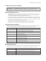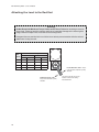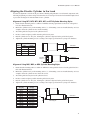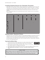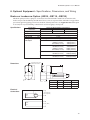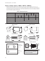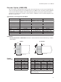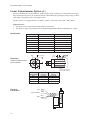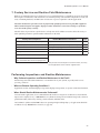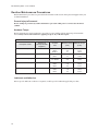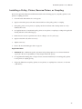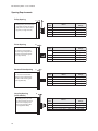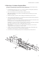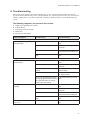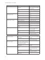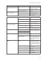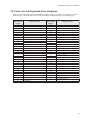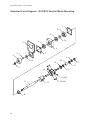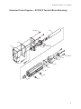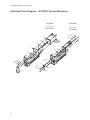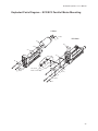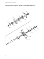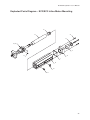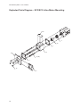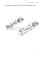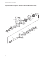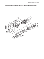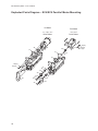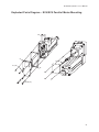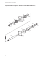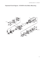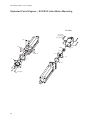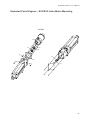
1
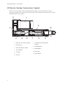
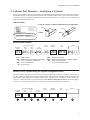
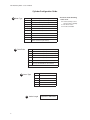
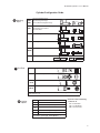
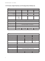
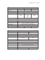
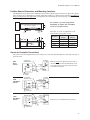
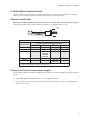
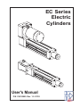
EC Series
Electric
Cylinders
User's Manual
P/N CUS10050 Rev. 1.0 07/03
Table of Contents
1. PRODUCT OVERVIEW .................................................................................................................... 1
EC SERIES FEATURES ......................................................................................................................1
EC SERIES SPECIFICATIONS .............................................................................................................1
EC ELECTRIC CYLINDER CONSTRUCTION (TYPICAL) ..........................................................................2
2. CYLINDER PART NUMBERS - IDENTIFYING A CYLINDER ........................................................ 3
IDENTIFY YOUR EC CYLINDER USING THE CYLINDER CONFIGURATION GUIDE .....................................3
3. EC SERIES SPECIFICATION AND CONFIGURATION REFERENCE .......................................... 6
4. MOUNTING YOUR EC CYLINDER ................................................................................................. 9
MOUNTING REQUIREMENTS ...............................................................................................................9
ATTACHING THE LOAD TO THE ROD END .........................................................................................10
ALIGNING THE ELECTRIC CYLINDER TO THE LOAD ............................................................................11
INSTALLING POSITION SENSORS FOR OVERTRAVEL PROTECTION .....................................................12
POSITION SENSOR DIMENSIONS AND MOUNTING LOCATIONS ............................................................13
5. APPLICATION CONSIDERATIONS ..............................................................................................15
COLUMN LOAD LIMIT .......................................................................................................................15
CRITICAL SPEED LIMIT ....................................................................................................................16
DUTY-CYCLE LIMITS .......................................................................................................................16
ENVIRONMENTAL SPECIFICATIONS ...................................................................................................17
PREVENTING EXPOSURE TO CONTAMINANTS ...................................................................................17
INSTALLING A VENT TUBE FITTING (INCLUDED WITH ALL EC CYLINDERS) ...........................................17
6. OPTIONAL EQUIPMENT - SPECIFICATIONS, DIMENSIONS, AND WIRING ............................19
BRAKE ON LEADSCREW OPTION (-BS24, -BS115, -BS230) ............................................................19
BRAKE ON MOTOR OPTION (-BM24, -BM115, -BM230) ..................................................................20
ENCODER OPTION (-EMK/-EM) ......................................................................................................21
LINEAR POTENTIOMETER OPTION (-L) .............................................................................................22
7. FACTORY SERVICE AND ROUTINE FIELD MAINTENANCE .....................................................23
PERFORMING INSPECTIONS AND ROUTINE MAINTENANCE .................................................................23
ROUTINE MAINTENANCE PROCEDURES ............................................................................................24
PREVENT INJURY TO PERSONNEL ....................................................................................................24
HARDWARE TORQUE .......................................................................................................................24
LUBRICANTS AND ADHESIVES ..........................................................................................................24
INSTALLING A PULLEY, PINION, REVERSE PINION, OR COUPLING ......................................................25
SPACING REQUIREMENTS ...............................................................................................................26
LUBRICATING THE LEADSCREW .......................................................................................................27
CHECKING/ADJUSTING DRIVE BELT TENSION ...................................................................................28
LUBRICATING GEARS ......................................................................................................................29
ALIGNING MOTOR PINION ................................................................................................................30
8. MOUNTING A CUSTOMER-SUPPLIED MOTOR .........................................................................31
9. TROUBLESHOOTING ...................................................................................................................33
10. PARTS LIST AND EXPLODED PARTS DIAGRAMS ................................................................. 39
EXPLODED PARTS DIAGRAM - EC2/EC3 PARALLEL MOTOR MOUNTING .....................................40 - 43
EXPLODED PARTS DIAGRAM - EC2/EC3 INLINE MOTOR MOUNTING ..........................................44 - 47
EXPLODED PARTS DIAGRAM - EC4/EC5 PARALLEL MOTOR MOUNTING .....................................48 - 51
EXPLODED PARTS DIAGRAM - EC4/EC5 INLINE MOTOR MOUNTING ..........................................52 - 55
11. WARRANTY AND SERVICE COVERAGE ..................................................................................57
INDEX..................................................................................................................................................59
i
EC Electric Cylinder - User s Manual
1. Product Overview
IDC s EC Series Electric Cylinders are designed for use in a wide variety of industrial, scientific, and commercial
applications requiring precise control of linear thrust, speed, or position. This manual will help you install, operate,
and maintain your EC Series Cylinder.
EC Series Features
From the EC2 to the EC5, the EC series is IDC s highest performance line of electric cylinders. Following are
several features that make the EC the cylinder of choice for the most demanding applications:
·
Robust design for highest loads and longest life possible
·
Precision rolled ballscrews for smoothness and accuracy
·
Environmentally sealed - All standard versions of EC cylinders are IP54 rated. An IP65-rated, Protective
Boot (-PB) option is available on all EC cylinders. This optional thrust tube boot prevents moisture and dry
contaminants from bypassing the thrust tube wiper seal.
·
Metric dimensions in accordance with ISO6431 - Meets the needs of customers who manufacture for the
international marketplace. Both English and Metric versions of threaded mounting options are standard.
·
ACME screws available on the EC2 and EC3 versions.
EC Series Specifications
Specifications vary for the four basic EC configurations (EC2, EC3, EC4, EC5). Please refer to Section 3, EC
Series Specification and Configuration Reference for specification parameters and configurations.
1
EC Electric Cylinder - User s Manual
EC Electric Cylinder Construction (Typical)
This cross-section of an EC4 cylinder, with parallel motor mounting, is provided to illustrate the typical
components of an IDC electric cylinder. Refer to Section 10, Parts List and Exploded Parts Diagrams, for a more
detailed breakdown of EC cylinders.
2
1
11
3
10
4
5
6
1.
Motor (may be customer supplied)
2.
Drive Housing
3.
Drive Train (belt drive shown)
4.
Thrust Bearings
5.
Leadscrew
6.
Drive Nut
7
5
8
7.
Internal Guide Flange (including
magnets)
8.
Rod End Bearing
9.
Rod End Wiper
10. Thrust Tube
11. Guide Cylinder
2
9
EC Electric Cylinder - User s Manual
2. Cylinder Part Numbers - Identifying a Cylinder
Your new EC cylinder will arrive with an IDC factory label attached as shown below. The factory label provides
a detailed breakdown of the cylinder model with all of its mechanical characteristics. This section can be used to:
1) identify a cylinder s mechanical characteristics based on the factory label, or 2) order a new EC cylinder with
different mechanical characteristics.
Label Location
Locations of Labels on Different Motor-Mounting Configurations
Label
7C Raymond Avenue
Label
Salem, NH 03079
TEL: 800-227-1066
www.DanaherMotion.com
Parallel
Electric Cylinder Model:
EC3-P32-15-05B-50-MS2-MT1E-BS-L
Serial Number: XXXXX XXXX XX X
Voltage: XXX V Rated Current: XX A
Inline
Model Number Example
Rod-Type
Cylinder
EC3
EC3 =
B23 =
15 =
05B =
50 =
Base Model Number
Drive
Motor
Ratio
Type
B23
15
Screw
Pitch, Type
05B
Stroke
Length
50
Product Series
NEMA 23 Frame, Brushless Servo Motor
1.5 to 1 Drive Ratio - Belt/Pulley
5 mm Lead Ballscrew
50-inch stroke
Cylinder
Mounting
MS2
MS2 =
MT1E =
BS =
L=
Rod
End
MT1E
Options
BS
L
Side Lugs Mounting
Male Threaded Rod End - English Threads
Brake on Screw Option
Linear Potentiometer Option
Identify Your EC Cylinder Using the Cylinder Configuration Guide
This fill-in-the-box section is provided for users who want to identify an existing EC cylinder or perhaps order a
new EC cylinder. To identify the mechanical characteristics of an existing EC cylinder, photocopy this page and
transcribe the model number from the factory label to boxes 2 through 8. To reconfigure or order a new EC, fill
in boxes 2 - 8 with codes for the new cylinder. Refer to the Cylinder Configuration Guide on the following pages
for boxes 2 - 8. See IDC s latest catalog or website (www.idcmotion.com) for more information.
Base Model Number
Rod-Type
Cylinder
Motor
Type
Drive
Ratio
Screw
Pitch, Type
2
3
4
Stroke
Lengt h
Cylinder
Mounting
Rod
End
Options
5
6
7
8
EC3
1
3
EC Electric Cylinder - User s Manual
Cylinder Configuration Guide
2 Motor Type
D
24VDC, 4.5 Amp, Permanent Magnet Motor
H
160VDC, 2 Amp, Permanent Magnet Motor
H4
160VDC, 5 Amp, Permanent Magnet Motor
P22[*x]
NEMA 23 Frame, Step Motor, 3 Stack
P32[*x]
NEMA 34 Frame, Step Motor, 2 Stack
S32[*x]
NEMA 34 Frame, Step Motor, 2 Stack
S42[*x]
NEMA 42 Frame, Step Motor, 2 Stack
B23
NEMA 23 Frame Brushless Servo Motor
B32
NEMA 34 Frame, Brushless Servo Motor
B41
NEMA 42 Frame, Brushless Servo Motor
X
3 Drive Ratio
Customer-Supplied Motor (motor described in
Options element of part number)
10
1.0:1 Drive Belt/Pulley
(1.0:1 exact ratio)
15
1.5:1 Drive Belt/Pulley
(1.5:1 exact ratio)
20
2.0:1 Drive Belt/Pulley
(2.0:1 exact ratio)
50
5.0:1 Drive Belt/Pulley
(5.0:1 ratio)
*70
7.0:1 Drive Belt/Pulley
(7.0:1 ratio)
100
10.0:1 Helical Gear
(10.1 exact ratio)
10L
1.0:1 Inline Coupling
(Direct 1:1 coupling is
the only ratio available for Inline Models)
*EC3 only
4 Screw Type
04A
4 mm/rev ACME leadscrew
05B
5 mm/rev ballscrew
10B
10 mm/rev ballscrew
16B
16 mm/rev ballscrew
25B
25 mm/rev ballscrew
32B
32 mm/rev ballscrew
5 Stroke Length
4
Specified in Millimeters
*Insert one of the following
codes for X:
N = 8 leads (windings can be
wired in Series or Parallel)
T = Pre-wired in Series
V = Pre-wired in Parallel
EC Electric Cylinder - User s Manual
Cylinder Configuration Guide
6 Mounting
Styles
MF1
MF2
MF3
Front Rectangular Flange
Rear Rectangular Flange
Front & Rear Rectangular Flange
MP2
MP3
Rear Double Clevis Mount (shown)
Rear Double Clevis Mount
with Pivot Base
MS1
Side End Angles
MS2
Side Lugs
MS6M Side Tapped Mounting Holes
MS6E
MT4
7 Rod Ends
Trunnion Mount
FC2
Clevis (includes MT1M)
FS2
Spherical Joint (includes FT1M)
FT1M
FT1E
Female Thread
MT1M Male Thread
MT1E
Note: Rod-End dimensions can be found in the latest IDC Catalog or on our website
www.idcmotion.com
8 Cylinder
Options
BM[*x] Brake on Motor
BS[*x] Brake on Leadscrew
EMK
L
Encoder on Motor (1000 line)
Linear Potentiometer
LR
Linear Rod Bearing (EC2 only)
PB
Protective Boot
*Insert one of the following
codes for X:
24 = 24 VDC Brake
115 = 115 VAC Brake
230 = 230 VAC Brake
Motor Mod Codes for X Motors (customer supplied)
also found in option part of Part Number
5
EC Electric Cylinder - User s Manual
3. EC Series Specification and Configuration Reference
EC2 - Specifications
Parameter
Motor Type
Max Load Capacity
EC2-D
EC2-H
EC2-S32/P22
EC2-B23
24 VDC Brushed
160 VDC Brushed
1.8ß Hybrid Stepper
Brushless Servo
N [lbs]
3230 [740]
Max No Load Speed
mm/s [in/s]
Repeatability
mm [in]
3600 [810]
840 [33]
930 [36.5]
800 [31.5]
–0.13 [–0.005]
–0.013 [–0.0005]
D2200
D2300
D2400
D2500B
SmartStep
Compatible IDC Controls
Performance Curves
1280 [50.5]
B8961
See Latest IDC Catalog or www.idcmotion.com
Configurations and Options Available - See Cylinder Configuration Guide for explanation of codes below
Drive Ratio
10, 15, 20, 50, 100, 10L
Screw Type
Stroke Length
04A, 05B, 16B
mm
50, 100, 150, 200, 250, 300, 450, 600, 750;
Custom lengths available in 1 mm increments
Cylinder Mounting
MF1, MF2, MF3, MS1, MS2, MP2, MP3, MS6M, MS6E, MT4
Rod End
FT1M, FT1E, MT1M, MT1E, FC2, FS2
Options
-BS, -EMK, -L,
-LR, -PB
-BM, -BS, -EMK,
-L, -LR, -PB
-BS, -EMK, -L,
-LR, -PB
-BM, -BS, -L,
-LR, -PB
EC3 - Specifications
Parameter
Motor Type
Max Load Capacity
EC3-P32
EC3-B23/B32
160 VDC Brushed
1.8ß Hybrid Stepper
Brushless Servo
N [lbs]
Max No Load Speed mm/s [in/s]
Repeatability
EC3-H
mm [in]
7200 [1620]
930 [36.5]
800 [31.5]
–0.025 [–0.001]
1280 [50.5]
–0.013 [–0.0005]
Compatible IDC Controls
SmartStep
Performance Curves
B8961
See Latest IDC Catalog or www.idcmotion.com
Configurations and Options Available - See Cylinder Configuration Guide for explanation of codes
Drive Ratio
10, 15, 20, 50, 70, 10L
Screw Type
Stroke Length
Cylinder Mounting
Rod End
Options
6
04A, 05B, 10B, 16B
mm
50, 100, 150, 200, 250, 300, 450, 600, 750, 1000;
Custom lengths available in 1 mm increments
MF1, MF2, MF3, MS1, MS2, MP2, MP3, MS6E, MT4
FT1M, FT1E, MT1M, MT1E, FC2, and FS2
-BM, -BS, -EMK, -L, -PB
-BS, -EMK, -L, -PB
-BM, -BS, -L, -PB
EC Electric Cylinder - User s Manual
EC4 - Specifications
Parameter
Motor Type
Max Load Capacity
Max No Load Speed
EC4-H4
EC4-P32
EC4-B32
160 VDC Servo
1.8ß Hybrid Stepper
Brushless Servo
N [lbs]
12000 [2700]
mm/s [in/s]
Repeatability
mm [in]
Compatible IDC Controls
1330 [52.5]
–0.025 [–0.001]
–0.013 [–0.0005]
H4301B
H4321B
H4501
Performance Curves
NextStep
SmartStep
S6002
S6961
S6962
B8001
B8961
B8962
See Latest IDC Catalog or www.idcmotion.com
Configurations and Options Available - See Cylinder Configuration Guide for explanation of codes
Drive Ratio
10, 15, 20, 50, 100, 10L
Screw Type
10B, 25B
Stroke Length
mm
Cylinder Mounting
50, 100, 150, 200, 250, 300, 450, 600, 750, 1000, 1500;
Custom lengths available in 1 mm increments
MF1, MF2, MF3, MS2, MP2, MP3, MS6M, MS6E, MT4
Rod End
FT1M, FT1E, MT1M, MT1E, FC2, FS2
Options
-BM, -BS, -EMK, -L, -PB
-BS, -EMK, -L, -PB
-BM, -BS, -L, -PB
EC5 - Specifications
Parameter
Motor Type
Max Load Capacity
Max No Load Speed
EC5-S42
EC5-B32/B41
1.8ß Hybrid Stepper
Brushless Servo
N [lbs]
25000 [5620]
mm/s [in/s]
Repeatability
1330 [52.5]
mm [in]
–0.013 [–0.0005]
Compatible IDC Controls
SmartStep
Performance Curves
B8961
See Latest IDC Catalog or www.idcmotion.com
Configurations and Options Available - See Cylinder Configuration Guide for explanation of codes
Drive Ratio
10, 15, 20, 50, 100, 10L
Screw Type
10B, 32B
Stroke Length
Cylinder Mounting
Rod End
Options
mm
50, 100, 150, 200, 250, 300, 450, 600, 750, 1000, 1500;
Custom lengths available in 1 mm increments
MF1, MF2, MF3, MS2, MP2, MP3, MS6M, MS6E, MT4
FT1M, FT1E, MT1M, MT1E, FC2, FS2
-BS, -EMK, -L, -PB
-BM, -BS, -L, -PB
7
EC Electric Cylinder - User s Manual
This page intentionally left blank
8
EC Electric Cylinder - User s Manual
4. Mounting Your EC Cylinder
Warning! Ensure that power to the electric cylinder is OFF before attempting any installation, adjustment, or modification of the cylinder mounting, rod end attachment, or the load.
Mounting Requirements
1.
2.
3.
4.
5.
CAUTION! When using pivot-mounting options (MP2, MP3, or MT4) with a pivot rod-end (FS2 or FC2),
it is recommended that the cylinder not be extended more than 95% of its full stroke. This increases the
system s rigidity and extends the life of the guide bearings and rod seal.
The structure on which the cylinder is mounted must be capable of holding three times (3X) the cylinder
load and be rigid enough to prevent undue deflection or distortion of the cylinder or its supporting members.
The cylinder must be mounted parallel to the travel of the load to ensure proper alignment (this is especially
important with externally guided loads using rails, bearings, etc.).
All mounting surfaces must be flat and clean to provide for secure and stable fittings.
Units with flat surface mounts (MF1, MF2, MF3, MS1, MS6) must be rigidly mounted.
Cylinder Mounting Styles
Each cylinder mounting style presents different application considerations. Find your mounting style(s) in the
table below and pay special attention to the corresponding Application Requirements column.
Cylinder Mounting Style
Application Requirements
MF1 - Front Flange
Not recommended for use in horizontal applications with stroke lengths greater than 300
mm unless there is additional support in the rear of the cylinder.
MF2 - Rear Flange
Not recommended for use in horizontal applications with stroke lengths greater than 300
mm unless there is additional support in the front of the cylinder.
MF3 - Front & Rear Flange
Do not allow the body of the cylinder to twist while aligning the front and rear mounting
flanges to their mating surfaces.
MP2 - Rear Clevis
Use a flexible rod end or load attachment to compensate for system misalignment.
Example: FC2, FE2, or FS2 rod ends
MS1 - Side End Angle Brackets
Each mounting screw must be able to withstand a peak shear-force of 4488 N (EC2); 8896
N (EC3); 15569 N (EC4); 26689 N (EC5).
MS2 - Side Lugs
Each mounting screw must be able to withstand a peak shear-force of 4488 N (EC2); 8896
N (EC3); 15569 N (EC4); 26689 N (EC5).
MS6 - Side Tapped Holes
Each mounting screw must be able to withstand a peak shear-force of 4488 N (EC2); 8896
N (EC3); 15569 N (EC4); 26689 N (EC5).
MT4 - Trunnion Mount
Use a flexible rod end or load attachment to compensate for system misalignment.
Mounting Rod Ends
As with mounting styles, different rod ends also require certain application considerations. Find your rod end(s)
in the table below and pay special attention to the corresponding Application Requirements column..
Rod End Style
Application Requirements
FC2 - Clevis w/MT1 Thread
Clevis must be secured by its locknut when in desired position. The mounting pin must be
secured with a cotter pin after it is inserted into the double clevis holes.
FS2 - Spherical Joint
Not recommended if stiff or rigid load attachment is required.
FT1 - Female Thread
Any attachment to an FT1 rod end must be secured in place by a locknut.
MT1 - Male Thread
Any attachment to an MT1 rod end must be secured in place by a locknut.
9
EC Electric Cylinder - User s Manual
Attaching the Load to the Rod End
Warning!
Do Not Exceed the Maximum Torque Limits on the Thrust Tube when attaching the load to
the rod end. Failure to heed this warning could cause irreparable damage to the internal guide
flange. Maximum torque limits are shown on the drawing below.
Hexagonal flats are provided at the end of the thrust tube to prevent rotation while the rod end
attachment is being secured.
Maximum Torque
EC
Series
A
B
N-m
ft-lbs
N-m
ft-lbs
EC2
68
50
27
20
EC3
88
65
41
30
EC4
163
120
68
50
EC5
163
120
68
50
Do Not Exceed A ft-lbs
torque in the Clockwise (CW)
direction
10
Do Not Exceed B ft-lbs torque
in the Counter Clockwise (CCW)
direction
Use wrench on flats to prevent
rotation of thrust tube during
load attachment
EC Electric Cylinder - User s Manual
Aligning the Electric Cylinder to the Load
Load-travel alignment is critical for the prevention of binding and premature wear of internal components. The
following alignment procedures and specifications have been developed for users who demand the highest level
of precision and longest life from their IDC electric cylinders.
Alignment Using MF1, MF2, MF3, MP2, MP3, or MT4 Cylinder Mounting Styles
1.
2.
3.
4.
5.
6.
Ensure that the mounting surface is within X millimeters from perpendicular to the travel of the guided
load. See illustrations below.
Mount the cylinder loosely to the mounting surface, i.e. all mounting screws are installed but they are loose
enough to allow the cylinder to move in the mounting.
Attach the guided load system to the cylinder rod end.
Reduce as much weight as possible from the guided load system.
Run the cylinder for 5 to 10 cycles, allowing the cylinder to align itself to the guided load system.
Tighten the cylinder mounting screws according to the torque specifications for your specific hardware.
EC
Series
X
mm
inches
load travel
EC2
0.03
.001
Mounting Surface
EC3
0.04
.0015
EC4
0.05
.002
X
EC5
0.05
.002
Mounting
Surface
load travel
X
Alignment Using MS1, MS2, or MS6 Cylinder Mounting Styles
1.
2.
3.
4.
5.
6.
Ensure that the mounting surface is within X millimeters from parallel to the travel of the guided load. See
table and illustration below.
Mount the cylinder loosely to the mounting surface, i.e. all mounting screws are installed but they are loose
enough to allow the cylinder to move from side to side.
Attach the guided load system to the cylinder rod end.
Reduce as much weight as possible from the guided load system.
Run the cylinder for 5 to 10 cycles, allowing the cylinder to align itself to the guided load system.
Tighten the cylinder mounting screws according to the torque specifications for your specific hardware.
Cyl. Length
mm [in]
X
mm [in]
50 [2]
100 [4]
150 [6]
200 [8]
250 [10]
300 [12]
450 [18]
600 [24]
750 [30]
1000 [40]
1250 [50]
1500 [60]
0.04 [.002]
0.06 [.002]
0.08 [.003]
0.10 [.004]
0.12 [.005]
0.14 [.006]
0.20 [.008]
0.26 [.010]
0.32 [.013]
0.42 [.017]
0.52 [.020]
0.62 [.024]
load travel
X
Mounting Surface
11
EC Electric Cylinder - User s Manual
Installing Position Sensors for Overtravel Protection
Although an elastomeric spring inside the cylinder is designed to prevent cylinder jams, position sensors (aka
limit switches) are required to prevent such potentially damaging jam conditions. If the motor is accidentally
commanded to move toward a hard-stop, position sensors can signal a stop before a collision occurs. To work
properly, position sensors must be positioned inward from the hard-stop, and wired correctly to the motor
controller.
Note: Using the physical limits of the cylinder (hard stops) will reduce cylinder life and can cause premature
component failure.
Position Sensor Specifications for Sensors Used on EC Electric Cylinders
Sensor Series
Sensor Type
Output Type
Connection
LED Color
PSR-1
PSR-2
PSN-2
Contact Closure
*PSP-2
Sinking, Open Collector (NPN)
Sourcing (PNP)
Norm. Closed
Norm. Open
Norm. Closed
Norm. Open
Norm. Closed
Green
Red
Green
Red
Yellow
Red
2 + shield, 26 AWG, 3 meters
Voltage
8-120V (AC or DC)
3 + shield, 26 AWG, 3 meters
5, 12, or 24 VDC
Current
5 mA @ 12 VDC; 10 mA @ 24 VDC
Power
0.24 W
Leakage Current (max)
Output
*PSP-1
Hall-Effect
Norm. Open
Leads (wiring)
Supply
PSN-1
Mechanical Reed
0.01 mA
DC Maximum
120VDC
AC Maximum
120VAC
8-30VDC
Current Max.
40mA
100mA
Power Max.
5W
3W
Operating Temp.
-4ß to 158ßF [-20ß to 70ßC]
Storage Temp.
-4ß to 176ßF [-20ß to 80ßC]
Environmental Rating
ITC Standard IP67
*Not compatible with IDC s motion controllers
Mounting Location - Deceleration Distance
The position sensor s location along the cylinder is associated with the beginning of a deceleration, not the final
stopping point. Therefore, position sensors must be mounted inward of the cylinder hard-stops to provide a
slowdown area to prevent jamming. The faster the approach speed, the longer it takes to stop the cylinder, so
deceleration distance varies with cylinder speed, load, and cylinder/control type. A small amount of adjustment
may be necessary during initial setup.
Important Installation Notes
1.
2.
3.
4.
Position sensors may be mounted along either side of an EC cylinder. Labels (example
POSITION
INDICATING
shown) indicate the sides of the cylinder where position sensors can be installed.
MAGNET
THIS SIDE
Distance between sensors should be 1.50 inches or more. If sensors are located closer
than 1.50 inches apart, they could trigger at the same time.
Using position sensors for end-of-travel protection reduces effective travel distance. Consult the factory.
IDC’s D2200, D2300 and D2400 series controls use only PSR-1 and PSN-1 position
sensors.
CAUTION
When installing a position sensor, tighten the clamp screw to a maximum 7.0 oz-in of torque. Failure
to heed this caution could cause irreparable damage to the sensor. Tighten the clamp screw gently and
only to the point where the sensor assembly feels secure and does not slide along the cylinder wall.
12
EC Electric Cylinder - User s Manual
Position Sensor Dimensions and Mounting Locations
The illustrations below show sensor mounting locations when cylinder magnet and sensor are physically aligned.
These locations are recommended as a starting point when setting up a cylinder for the first time. Depending on
the speed and payload of the application, sensors may be moved inward to prevent a hard-stop crash when the load
travels at full speed past a limit switch.
See Caution on previous page before
attempting to tighten the installation
screws on a position sensor
Top View of TC Cylinder
Internal Magnets
Sensors
Dimensions A and B are approximate end-ofstroke locations for the position sensors.
Phillips-Head
Screw
11.2
[0.44]
EC Series
Dim A
mm [in]
Dim B
mm [in]
EC2
73.3 [2.90]
48.3 [1.90]
EC3
77.0 [3.03]
56.6 [2.23]
EC4
137.0 [5.39]
63.0 [2.48]
EC5
137.0 [5.39]
63.0 [2.48]
B
A
9.9
[0.39]
29.5
[1.16]
Side View of TC Cylinder
Sensor-to-Controller Connections
The sensor connection diagrams below show wiring color codes and controller inputs for connecting each type of
position sensor.
PSR
Reed
Sensor
Controller
2-Conductor
Shielded Cable
Internal
Supply
Brown
Blue
Controller
Inupt
Note: The black wire in Quick Disconnect cables is
not used with any version of the PSR (Reed) sensor.
In the above drawing, only the blue wire, brown wire,
and shield are connected.
COM
Shield
Sensor
(Reed)
Detector
PSN
Hall-Effect
Sensor
Controller
3-Conductor
Shielded Cable
+12/24V
Brown
DC Supply
Controller
Input
Black
Blue
COM
Shield
Sensor
(Hall-Effect)
Controller
3-Conductor
Shielded Cable
Brown
Detector
*PSP
Hall-Effect
Sensor
+12/24V
Controller
Input
*PSP sensor is not compatible with IDC controls.
Black
Blue
DC Supply
COM
Shield
Sensor
(Hall-Effect)
13
EC Electric Cylinder - User s Manual
This page intentionally left blank
14
EC Electric Cylinder - User s Manual
5. Application Considerations
Certain conditions can limit cylinder performance and should be addressed prior to installation and operation.
Adherence to the following application guidelines will ensure a successful application.
Column Load Limit
Exceeding the Column Load Limit will cause the leadscrew to buckle and become permanently damaged.
The Load Limit Table below contains Column Load Limits per stroke length and screw type.
Thrust
Load
Compression (column) Load
Load Limit Table for Standard Stroke Lengths
*Column Load Limit (N) per EC Series
with Applicable IDC Screw Type in Parentheses
EC Cylinder
Stroke Length
EC2
EC3
2500 (04A)
4900 (16B)
EC4
EC5
50 - 600 mm
750 mm
1000 mm
2780 (16B)
4650 (04A)
5340 (10B)
6530 (05B)
1250 mm
10300 (10B)
1500 mm
7400 (10B)
8600 (25B)
*Shaded areas indicate NO Column Loading Restriction (for example: Column Load Limits do
not apply to any length of EC5 cylinder or to 32B Screws).
Column Load Limits for Custom Stroke Lengths
If you require a Column Load Limit for a custom stroke length between 750 and 1500 mm, consider the following
options:
5.
Contact IDC Applications Engineering for a custom Column Load Limit.
6.
Use the Column Load Limit for the next shorter stroke length. Example: for an EC3 of 1100 mm with an
04A screw, use 4650 N.
15
EC Electric Cylinder - User s Manual
Critical Speed Limit
All leadscrew systems have a critical speed at which harmonic vibrations begin to occur. Sustained operation
beyond this critical speed limit (see tables below) may cause the leadscrew to vibrate or whip violently,
eventually bending or warping the screw (see illustration).
Observing the maximum speed limits in
the tables below will help prevent damage
to your EC cylinder.
L
Maximum Speed per Cylinder Stroke Length (Speed = mm/sec)
Screw
Type
50 - 200 mm
300 mm
450 mm
600 mm
EC2 EC3 EC4 EC5 EC2 EC3 EC4 EC5 EC2 EC3 EC4 EC5 EC2 EC3 EC4 EC5
04A
233
200
219
200
119
144
72
89
05B
414
261
310
261
172
199
103
119
10B
16B
25B
32B
533
388
1280
533
993
1333
388
866
398
550
239
530
1333
1333
388
331
350
318
1059
1333
263
Table continued
657
1333
1120
Note: Shading indicates non-applicability.
Important Note:
IDC programmable controls have a maximumvelocity parameter that can be configured not
to exceed the critical speed.
Screw
Type
Maximum Speed per Cylinder Stroke (Speed = mm/sec)
750 mm
1000 mm
1250 mm
1500 mm
EC2 EC3 EC4 EC5 EC3 EC4 EC5 EC4 EC5 EC4 EC5
04A
48
61
05B
71
84
10B
16B
25B
32B
212
230
33
48
185
254
216
96
119
156
63
99
53
72
127
462
298
814
171
499
131
316
229
Duty-Cycle Limits
Duty-cycle is the percentage of ON Time divided by Total Cycle Time for the worst-case 10-minute period.
During operation, duty-cycle represents the maximum acceptable power dissipation of the motor and the frictional
heat losses of the internal cylinder components, primarily the leadscrew/drivenut assembly. In general, ballscrew
cylinders are rated for 100% duty cycle and ACME screws are rated for a maximum of 60%. Your motor may also
have duty-cycle limitations. Consult your IDC Catalog or www.idcmotion.com for more information on dutycycles. Exceeding the recommended duty-cycle will damage the motor or internal cylinder components.
16
EC Electric Cylinder - User s Manual
Environmental Specifications
The following environmental specifications must be observed for optimal cylinder performance:
Temperature Rating - The operational temperature range for all EC cylinders is -30ß to 70ß C [-22ß to 158ß F].
When operating below 2ß C [35ß F], a vent tube must be installed (see below).
Preventing Exposure to Contaminants
Liquids: Standard EC cylinders are water-resistant for environments with a slight mist on the cylinder body but
not on the thrust tube. If liquid or moisture contaminates internal components, damage may occur. Standard EC
cylinders are IP54-rated.
The IP65-rated Protective Boot option (-PB) is available to protect the thrust tube/wiper interface. The standard
EC cylinder provides a seal between the motor and cylinder body, but does not protect the motor itself.
For applications where exposure is unavoidable with a corrosive liquid or a pressurized liquid, an external
protective enclosure is recommended. Consult the factory for assistance.
Solid Particles: Rod-type cylinders are generally well protected against particle contaminants. For
environments with exposure to fine or abrasive particles, the standard EC cylinder provides added resistance to
entry by sealing mating surfaces with gaskets during assembly. The Protective Boot (-PB) option is
recommended when the thrust tube/sleeve bearing interface is exposed to abrasive particles or water spray.
Installing a Vent Tube Fitting (included with all EC cylinders)
A Vent Tube is required when:
· Any EC cylinder is equipped with the -PB option.
· Operating any EC cylinder below 2ß C [35ßF].
· Operating any non PB-equipped EC cylinder in an
environment of solid contaminants (i.e. dust,
paper, or wood particles).
3. Connect tubing (customer-supplied) to the vent
tube fitting. See table for size of tubing required.
4. If the cylinder has the -PB option and/or is being
operated below 2ß C [35ß F], connect the other
end of the tubing to a non-contaminated air
source of 0 psi.
Installation
1. Remove breather plug from all cylinders except
EC4 and EC5 with -PB option.
2. Install white plastic vent tube fitting.
EC4 and EC5 with Protective Boot (-PB) Option
EC2, EC3, EC4, EC5
Vent Tubing Sizes
If the cylinder does not have the -PB option, and
is being operated in an environment of solid
contaminants, connect the other end of the tubing
to a non-contaminated positive pressure source
of 2 to 3 psi.
EC Series
EC2 and EC3
Size Tubing Required
1/4-inch inside diameter
EC4 and EC5
3/8-inch inside diameter
EC4 and EC5 with PB option
3/4-inch inside diameter
17
EC Electric Cylinder - User s Manual
This page intentionally left blank
18
EC Electric Cylinder - User s Manual
6. Optional Equipment - Specifications, Dimensions, and Wiring
Brake on Leadscrew Option (-BS24, -BS115, -BS230)
This brake option provides a spring-set, electrically-released friction brake mounted to an extension of the
leadscrew. It prevents backdriving when the unit is at rest, or in case of power failure. The brake is engaged when
power is not applied. Applying power releases the brake, allowing motion to occur. Application Note: This option
is used only for in-position holding, it should not be used for stopping a moving load.
Specifications
Specification
Parameters
Voltage
Power
Watts
Holding Torque N-m [in lbs]
Cable Length
m [ft]
Holding Force with -BS
Brake Option
Leadscrew-Mounted Brake Configurations
-BS24
-BS115
-BS230
24 VDC
115 VAC
230 VAC
EC2=12.5 EC3=7 EC4/5=15
EC2=3.9 [35] EC3=6.7 [60] EC4/5=39.2 [350]
3.7 [12]
EC Configuration
Screw Type
Holding Force
EC2
16B Ball (16 mm/rev)
1550 N [350 lbs]
05B Ball (5 mm/rev)
3600 N [810 lbs]
04A ACME (4 mm/rev)
3600 N [810 lbs]
EC3
16B Ball (16 mm/rev)
2660 N [600 lbs]
10B Ball (10 mm/rev)
4260 N [960 lbs]
05B Ball (5 mm/rev)
7200 N [1620 lbs]
04A ACME (4 mm/rev)
7200 N [1620 lbs]
EC4
25B Ball (25 mm/rev)
9940 N [2230 lbs]
10B Ball (10 mm/rev)
12000 N [2700 lbs]
EC5
32B Ball (32 mm/rev)
7770 N [1750 lbs]
10B Ball (10 mm/rev)
24800 N [5590 lbs]
.23 Quick-Disconnect Cable
1.50 Minimum Bend Radius
Dimensions
.57
H
Brake Cover
D
EC Series
L
EC2
EC3
EC4/EC5
Electrical
Connections
+
Brake
Dim D
Dim H
78.2 [3.08] 155.1 [6.10]
97.3 [3.83] 183.3 [7.22]
141.7 [5.58] 245.0 [9.64]
Dim L
69.3 [2.73]
84.3 [3.32]
99.9 [3.94]
115 VAC (-BS115)
230 VAC (-BS230)
Rectifier
Coil
–
Brake
24 VDC (-BS24)
Coil
19
EC Electric Cylinder - User s Manual
Brake on Motor Option (-BM24, -BM115, -BM230)
The motor shaft-mounted brake can be an advantage because brake torque is multiplied by the belt or gear
reduction and does not interfere with certain rear cylinder-mounting options. A broken drive belt will render the
motor-mounted brake inoperable. Note: This is a static brake, intended only for in-position holding. It should not
be used for routinely stopping a moving load.
Brake on Motor Specifications
Parameter
Brake Specifications per Cylinder Configuration
Cylinder
EC2-H, EC3-H, EC4-H
EC2-B
EC3-B
EC4-B
EC5-B
Motor Type
H, H4
B23
B23
B32
B32
B32
B41
Brake Type
-BM24
-BM115
-BM230
-BM24
-BM24
-BM24
Voltage
24 VDC 115 VAC 230 VAC
24 VDC
24 VDC
24 VDC
Current
Amps
0.25
0.05
0.03
0.21
0.52
0.88
Power
Watts
6
5
12.48
21.12
Holding Torque N-m [in-lbs]
1.1 [10]
1.1 [10]
6.7 [60]
27 [240]
Cable Length
m [ft]
3.7 [12]
See Note Below
Holding Force
Consult the Factory
Note: Brake wiring included in B23 motor cable. Motor cable available in 12, 25, and 50-foot lengths.
Dimensions
H4 Motor with Brake
H Motor with Brake
3.7 m [12']
Brake Cable
106.7 [4.20]
79.25 [3.12]
190 [7.48] MAX
221.49 [8.72]
B23 Motor with Brake
B32 Motor with Brake
50.8 [2.00]
MAX
SQ 57.15
[2.25]
63.5 [2.50]
MAX
SQ 84.07
[3.31]
201.9 [7.95] MAX
B41 Motor with Brake
Electrical Connections
+
Brake
260.1 [10.24] MAX
71.12 [2.80]
MAX
115 VAC (-BM115)
230 VAC (-BM230)
Rectifier
Coil
SQ 127.99
[5.00]
–
266.95 [10.51] MAX
+
Brake
24 VDC (-BM24)
Coil
–
20
Note:
Observe polarity when using a -BM24 Brake
with a B23, B32, or B41 Motor.
EC Electric Cylinder - User s Manual
Encoder Option (-EMK/-EM)
The encoder option for EC-applicable motors provides an incremental rotary encoder, factory-mounted directly
to the rear of the D, H, P22, P32, S32, and S42 IDC motors. The -EMK encoder is an industry-standard, 1000-line
version, and the -EM is the 500-line version. The digital pulse output is used to provide position feedback to
external devices such as motor controllers, counters, or PLC s. A 2000-line encoder is standard equipment on the
B23, B32, and B41 motors.
Specifications per EC-Applicable IDC Motor
Parameter
Pulses per Revolution
Output Pulse Format
Cable Length/Type
Voltage
Current
Max. Speed
Weight
m [ft]
kg [oz]
D, H, P22, S32, S42, Motors
P32 Motor
*B23, B32, B41 Motors
-EMK 1K line (4K post-quad) -EMK 1K line (4K post-quad) 2000 line (8000 post-quad)
-EM 500 line (2K post-quad)
-EM 500 line (2K post-quad)
Incremental, Dual Square Wave Quadrature, with Index Pulse
3.7 [12]/Leads
3.7 [12]/Leads
3.7 [12]/MS Connector
5 VDC –5%
120 mA
135 mA
200 mA
6000 rpm
12000 rpm
6000 rpm
0.17 [6.0]
.057 [2.0]
0.25 [8.8]
[oz-in-sec2]
5.1 x 10⁻⁹ [7.3 x 10⁻⁷]
3.1 x 10⁻⁷ [4.4 x 10⁻⁵]
Operating Temp.
…C […F] -10 to +70 [+14 to +158]
-10 to +100 [+14 to +212]
Storage Temp.e
…C […F] -20 to +80 [-4 to +176]
-30 to +110 [-22 to +230]
*Not an option. Encoder is standard equipment on these motors.
Inertia
kg-m2
1.0 x 10⁻⁶ [1.4 x 10⁻⁴]
-20 to +100 [-4 to +212]
-25 to +100 [-13 to +212]
Dimensions
P32, S32, S42, B32, B23, and B41 Motors: Encoder is enclosed within the standard motor housing - no dimensional changes.
H Motor
D, P22 Motor
30.48
[1.2]
25.4
[1.00]
79.8
[3.14]
54.1
[2.13]
Encoder Cover
Encoder Cover
Encoder
Connections
Motors: D, H, P22, P32, S32, S42
Signal
Color Code
Signal
Motors: B23, B32, B41
Color Code (See Note)
A+
Red
A+
Blue
Blue
Blue
A-
Pink or Purple
A-
Blue/Black
Yellow
Blue/White
B+
Green
B+
Green
Yellow/White
Yellow
B-
Blue
B-
Green/Black
Red/ White
Yellow/White
Z+
Yellow
Z+
Violet
Blue/White
Brown
Z-
Orange
Z-
Violet/Black
Black/White
Brown/White
+5 VDC
White
+5 VDC
Red
Red
Red
COM
Black
COM
Black
Black
Black
Note: Due to different cable suppliers, your encoder cable will contain
one of three possible color codes. Each column represents a color
code for a different cable. Find the color code that matches your cable
and use that column only.
21
EC Electric Cylinder - User s Manual
Linear Potentiometer Option (-L)
The Linear Potentiometer resides within the cylinder housing and is energized by an external DC power supply.
The potentiometer wiper moves in conjunction with the cylinder thrust tube providing an analog voltage feedback
signal which is proportional to the linear displacement.
Example: Using a 5 volt supply, 0VDC = 0% Stroke; 2.5VDC = 50% Stroke; and 5 VDC = 100% Stroke
Application Notes
1. This option is not recommended for high vibration environments.
2. This option is required when the EC is used with IDC D2500, H3500, H4500, and B8500 series controls.
Specifications
Stroke (mm)
Resistance (ohms)
50
3000 – 20%
–1%
100
6000 – 20%
–1%
150
9000 – 20%
–1%
200
9000 – 30%
–1%
250
9000 – 30%
–1%
300
7000 – 30%
–1% (5% to 95% of function)
450
7000 – 30%
–1% (5% to 95% of function)
600
7000 – 30%
–1% (5% to 95% of function)
1.18 [30.0]
Dimensions
(Linear Pot top-mounted
on EC cylinder)
Max. Non-Linearity
0.50
[12.7]
A
Cable:
0.17 [4.3], R0.51 [13.0]
Minimum Bend Radius
B
EC
Cylinder Model
EC2
EC3
EC4
EC5
Electrical
Connections
+VDC
Wiper Feedback
GND
DIM A
mm [in]
37.3 [1.47]
43.7 [1.72]
54.5 [2.15]
54.5 [2.15]
Brown
Black
Blue
Shield
22
DIM B
mm [in]
28.5 [1.12]
34.8 [1.37]
46.1 [1.82]
46.1 [1.82]
EC Electric Cylinder - User s Manual
7. Factory Service and Routine Field Maintenance
While we recommend factory service in most cases, we recognize that it may occasionally be necessary to perform
minor repairs or maintenance in the field. Such cases include replacing worn or broken components (i.e. belts, rod
ends, or mounting hardware) and lubrication of leadscrew or gears as required in extreme applications.
All routine maintenance procedures must be performed by qualified personnel, using only IDC-supplied or
IDC-recommended parts and supplies. Improper routine maintenance which causes damage or premature
wear will void the factory warranty.
The table below is provided as a quick reference to help users decide whether to return a unit to the factory or
allow qualified personnel to perform routine maintenance in the field.
Factory Service Required
Routine Maintenance Procedures
Page #
Belt/Pulley Ratio Conversion (1:1, 1.5:1, 2:1)
Pulley and Pinion Installation
Helical Gear System Ratio Conversion (5:1 and 10:1)
Lubricating the Leadscrew (excluding -BS and -L options)
22-23
24
Leadscrew Modification
Checking and Adjusting Drive Belt Tension*
25
Motor Orientation Modification
Lubricating Gears
26
Mounting or Rod End Modification
*Aligning Motor Pinion
27
Cylinder Option Modification (-BS and -L)
Any Repair to Motor Pulley, Drive Belt, Gear, Motor
Pinion, Intermediate Gear, or Inline Coupling/Sleeve
*This procedure was developed for users of IDC motors, but it may
also be applicable to certain customer-supplied motors.
Performing Inspections and Routine Maintenance
·
Why Perform Inspections and Routine Maintenance in the Field?
Periodic inspection and routine maintenance can extend the life of your cylinder, especially under extreme
operating conditions.
·
What are Extreme Operating Conditions?
Applications such as continuous high speed operation, high speed stops/starts, or exposure to harsh environments.
·
When Should Routine Maintenance be Performed?
In such extreme applications, it is recommended that the leadscrew and gears be re-lubricated, and an internal
inspection be completed every *1,000,000 inches of cylinder travel. Inspection/re-lubrication typically consists of
partial disassembly, followed by cleaning, visual evaluation, and lubrication.
*EC2 and EC3 cylinders with ACME leadscrews operating in high load/high duty-cycle applications should be
re-lubricated every 200,000 inches of travel (see page 24).
23
EC Electric Cylinder - User s Manual
Routine Maintenance Procedures
Routine maintenance procedures are provided in the remainder of this section. Order parts and supplies from your
local IDC Distributor.
Prevent Injury to Personnel
Do not attempt to perform any routine maintenance procedure while power is connected to the motor/
cylinder.
Hardware Torque
Before attempting any routine maintenance procedure, become familiar with the Torque Specification Table
below. Always refer to this table before applying torque to any of the listed parts.
Torque Specification Table
Description of Part
Reference #
(see Exploded Parts
Diagrams)
Screw, Guide Cylinder
Hardware
Size
Maximum Torque
(N-m)
Maximum Torque
(in-lbs)
17, 33, 53
M5X.8
M6X1
M10X1.5
4.24
9.9
41
50.89
87.62
362.86
Screw, Set
22, 36
M4X.7
M6X1
0.94
4.3
8.32
38.06
Screw, Set, Coupling
4, 58
10-24 UNC
1/4 - 20 UNC
2.83
4.53
25.05
40.09
Screw, Motor Mounting
39
M4X.7
M5X.8
M6X1
2.9
5.75
9.9
25.67
50.89
87.62
Screw, Cover Plate
18
M4X.7
M5X.8
M6X1
2.9
5.75
9.9
25.67
50.89
87.62
Lubricants and Adhesives
When a specific lubricant or adhesive is required, it will be specified within the applicable procedure.
24
EC Electric Cylinder - User s Manual
Installing a Pulley, Pinion, Reverse Pinion, or Coupling
Refer to the applicable illustration and dimensions table on the following page for your pulley, pinion, reverse
pinion, or coupling placement.
1.
Clean the motor shaft and bore free of any grease.
2.
Apply Loctite #680 (green) to the motor shaft and the bore of the pulley, pinion, or coupling.
3.
Slide pulley, pinion, reverse pinion, or coupling onto the motor shaft with a rotating motion to evenly
distribute the Loctite.
4.
See Application Note # 2. Position the pulley, pinion, reverse pinion, or coupling according to the applicable
drawing and table on the following page.
5.
Ensure that one setscrew is positioned on a flat, in a dimple, over a key or keyway.
6.
Apply Loctite #262 (red) to the setscrew(s).
7.
Tighten setscrew(s).
8.
Refer to the motor-mounting procedure on page 28.
Application Notes
1.
WARNING! The combination of pulley placement and operating torque may exceed motor shaft-load
capacity. It is the user s responsibility to verify adequate shaft-load capacity.
2.
If a supplemental mounting plate or adapter is used, it must be installed before measuring pulley, pinion,
reverse pinion, or coupling spacing.
3.
All spacing dimensions for pulleys, pinions, reverse pinions, or couplings have a tolerance of –0.13 mm
(–.005 inches).
25
EC Electric Cylinder - User s Manual
Spacing Requirements
Pulley Spacing
A
EC
Series
Pulley spacing A must be measured from the inner face of the
pulley to the face of the mounting plate (see App. Note #2)
Pinion Spacing
Coupling spacing D must
be measured from the inner
face of the coupling to the
face of the mounting plate
(see Application Note)
26
EC2
D, H, P22, S32, B23, NEMA 23/34
11.63 [0.458]
EC3
D, H, P32, S32, B23/32, NEMA 23/34
13.08 [0.515]
EC4
H4, P32, S32, B32, NEMA 34/42
18.06 [0.711]
EC5
H4, P32, S32/42, B32/41, NEMA 34/42
18.06 [0.711]
EC
Series
Motors
EC2
S32, P22, NEMA 23/34
Dimension B
mm [in]
9.40 [0.370]
B23
3.68 [0.145]
EC3
D, P32, S32, B23/32, NEMA 23/34
3.30 [0.130]
EC4
H4, P32, S32/42, B32, NEMA 34/42
2.82 [0.111]
EC5
P32, S32/42, B32, NEMA 34/42
2.82 [0.111]
EC
Series
Motors
EC2
H & D only
6.73 [0.265]
EC3
H only
10.67 [0.420]
EC4
N/A
N/A
EC5
H4 & B41 only
15.72 [0.619]
EC
Series
Motors
EC2
D, H, P22, S32, B23, NEMA 23/34
EC3
D, H, P32, S32, B23/32, NEMA 23/34
7.62 [0.300]
EC4
H4, P32, S32, B32, NEMA 34/42
8.79 [0.346]
EC5
H4, P32, S32/42, B32/41, NEMA 34/42
8.79 [0.346]
C
C must be measured from
the inner edge of the pinion to
the face of the mounting plate
(see App. Note #2)
Coupling Spacing
(inline motors)
Dimension A
mm [in]
B
B must be measured from
the inner edge of the pinion to
the face of the mounting plate
(see App. Note #2)
Reverse Pinion Spacing
Motors
Dimension C
mm [in]
D
Dimension D
mm [in]
8.00 [0.315]
EC Electric Cylinder - User s Manual
Lubricating the Leadscrew
In high-load and/or high duty-cycle applications, EC2 and EC3 cylinders with ACME screws should be relubricated every 200,000 inches of travel. All other EC cylinders should be re-lubricated every 1,000,000 inches
of travel. EC2 and EC3 cylinders with ACME screws, and all EC4 and EC5 cylinders include a lube port and lube
adapter (nozzle) for a standard lubrication dispenser (grease gun).
Note: Do not attempt to lubricate the leadscrew of a cylinder with the -L (Linear Potentiometer) Option.
This procedure must be done at the factory.
Recommended Lubricants
Type of Leadscrew
Type of Lubricant
Ballscrews with 05B, 10B, 16B, 25B, and 32B Screws
NLGI Grade 2, Synthetic Base Lithium Grease
ACME Screws with Bronze ACME Nut (04A Screws)
NLGI Grade 2, Synthetic Base Grease with PTFE Additive
Lubricating EC2/EC3 Ballscrews
1. Remove upper rear cover plate from the gear housing
(EC2 only) by removing two (2) SHCS.
2. Remove main rear cover plate by removing four (4)
SHCS.
3. Loosen two (2) SHCS (inside gear housing) that secure
the upper part of the guide housing. These screws must
be loosened in consecutive increments; i.e. 2 turns on
one screw, then 2 turns on the other, repeating until each is
loose. Note: these are captive screws and cannot be
removed as shown in the illustration below.
4. Remove guide housing by sliding it away from the thrust
tube.
5. Move the drive nut (attached to thrust tube) to the far end
of the leadscrew.
6. Remove as much of the old grease from the leadscrew as
possible.
7. With most of the leadscrew exposed, apply no more than
0.8 mm (.03’’) of the recommended lubricant over the
length of the screw. Run the drivenut over the screw
length to spread the grease evenly. Wipe off any excess
grease expelled from the leadscrew by the drivenut.
8. Reassemble Unit.
Note: After lubricating the leadscrew, check belt tension
on belt-driven cylinders (next page).
1
4
5
6
3
2
Lubricating EC2/EC3 ACME Screws and All
EC4/EC5 Ballscrews
1. Remove lube plug.
2. Move cylinder to center stroke.
3. Install the IDC-supplied lube nozzle on your lube
dispenser (aka grease-gun).
4. Insert lube nozzle through lube opening and onto the
grease fitting.
1
5. Caution- Do Not Overfill the Leadscrew with
Grease! Pump only 2.3 to 2.8 grams (.08 to 1.0 oz) of
grease per 304.8 mm (12 inches) of cylinder travel
into the leadscrew.
27
EC Electric Cylinder - User s Manual
Checking/Adjusting Drive Belt Tension
1.
Ensure power to the motor is OFF and the load is removed from the thrust tube.
2.
Remove rear cover plate(s) as necessary for your particular EC cylinder.
3.
Using finger pressure, push the drive belt inward. The belt should not deflect more than 3.17 mm (.125 inch)
from a stationary centerline. If the drive belt deflects more than 3.17 mm (.125 inch), proceed to the
following section that applies to your motor.
Adjusting Belt Tension on D and H Motors
1.
Loosen two (2) motor-adjustment screws inside drive housing (shown below left) just enough to allow the
motor to move. Both screws are in slots which allow up/down movement of the motor to change belt
tension.
2.
Move the motor up or down to adjust belt tension. While maintaining proper tension by hand, tighten both
screws. Check belt tension again and reassemble unit.
Adjusting Belt Tension on P22, P32, S32, S42, B23, B32, and B41 Motors
1.
Loosen four (4) external motor mounting/adjustment screws (shown below right) just enough to allow the
motor to move. All screws are in clearance holes which allow just enough up/down movement to adjust the
belt tension.
2.
Move the motor up or down to adjust belt tension. While maintaining proper tension by hand, tighten all
screws. Check belt tension again and reassemble unit.
D/H/H4 Motors
Motor
Adjustment
Screw
P22/P32/S32/S42/B23/B32/B41 Motors
Motor
Adjustment
Screw
Motor
3.17 mm (.125’’)
Maximum
Belt Deflection
28
Motor
Mounting/
Adjustment
Screw (4)
EC Electric Cylinder - User s Manual
Lubricating Gears
Recommended Lubricant: NLGI Grade 2, Synthetic Base Lithium Complex EP Grease
1.
Remove rear cover plate(s) as necessary for your particular EC cylinder.
Note: Cylinder with -BS (Brake on Leadscrew) option requires removal of the top cover plate only on EC2
cylinders.
2.
Remove as much of the old grease from the gears as possible.
3.
With the gears exposed, apply an ample amount of lubricant (6.35 mm [.25 in] or more) to all surface
contact areas of gear train as shown in the illustration below. Reassemble unit.
3
29
EC Electric Cylinder - User s Manual
Aligning Motor Pinion
1.
Ensure power to the motor is OFF and the load is removed from the thrust tube.
2.
Remove rear cover plate(s) as necessary for inspection. For cover plate removal, refer to steps 1 and 2 in
Lubricating Gears earlier in this section. Reinstall cover plate(s).
Aligning Motor Pinion on D, and H Motors (shown below)
1.
Loosen two (2) mounting/alignment screws just enough to allow the motor to move. Both screws are in slots
which allow up/down movement of the motor to align the motor pinion.
2.
Move the motor pinion into the fully-meshed or seated position against the intermediate gear (i.e. pinion will
not move any farther). See #2 in photo below.
3.
From the fully-meshed position, back off or move the pinion gear away from the intermediate gear 0.076 to
0.203 mm (.003 to .008 in). See #3 in photo below.
4.
While maintaining proper position by hand, tighten mounting/alignment screws. Install upper cover plate.
Aligning Motor Pinion on P22, P32, S32, S42, B23, B32, and B41 Motors
1.
Loosen four (4) mounting/adjusting screws just enough to allow the motor to move. All screws are in
clearance holes which allow just enough up/down movement to adjust the motor pinion.
2.
Move the motor pinion into the fully-meshed or seated position against the intermediate gear (i.e. pinion will
not move any farther). See step 2 on the D/H/H4 Motor photo.
3.
From the fully-meshed position, back off or move the pinion gear away from the intermediate gear 0.076 to
0.203 mm (.003 to .008 in). See step 3 on the D/H/H4 Motor photo.
4.
While maintaining proper position by hand, tighten mounting/alignment screws. Install upper cover plate.
D/H/H4 Motors
2
.003 to .008’’ gap
between pinion and
intermediate gears
30
3
P22/P32/S32/S42/B23/B32/B41 Motors
Mounting/Alignment
Screw (2 screws on D
& H motors; 4 screws
on B and P Motors)
Motor
EC Electric Cylinder - User s Manual
8. Mounting a Customer-Supplied Motor
This procedure is provided for the user who will be mounting a non-IDC motor on an EC Cylinder. For this
procedure it is assumed that the EC cylinder has been received without a motor.
1.
For parallel-mounted motors only, remove rear cover plate(s) from the gear housing (EC2 cylinders have
two covers; all other EC cylinders have a one-piece cover plate).
2.
Remove motor-mounting screws and washers from the cylinder motor mount.
Note: If motor mounting screws and washers are not installed in the motor mount, they can be found
packaged in a separate bag.
3.
Install the motor pulley, gear pinion, or inline coupling per the installation procedure in section 7.
4.
Using the following method appropriate to your application, insert the motor shaft and motor pilot into the
gear housing through the hole in the mounting plate.
Drive Belt: As you slide the motor and pulley through the mounting plate, lift the drive belt onto the teeth of
the drive pulley. Refer to Checking/Adjusting Drive Belt Tension in section 7.
Gear Drive: As you slide the motor and gear pinion through the mounting plate, gently engage and mesh the
pinion with the intermediate gear. Refer to Aligning Motor Pinion in section 7.
Inline Mounting: As you slide the motor and coupling through the mounting plate, rotate the motor
coupling until it lines up the coupling sleeve inside the cylinder.
5.
Continue to slide the motor shaft through the mounting plate until motor flange is flush with the motor
mounting plate and the motor pilot is centered inside the mounting plate.
6.
Secure the motor to the mounting plate using the motor mounting hardware previously removed.
1
3
2, 6
4, 5
31
EC Electric Cylinder - User s Manual
This page intentionally left blank
32
EC Electric Cylinder - User s Manual
9. Troubleshooting
This section offers assistance when troubleshooting basic electric cylinder problems related to mechanical
operation. When troubleshooting electric cylinder problems, the cause may be related to the drive or motor used
with the cylinder. Refer to your drive/control user s manual for additional assistance on troubleshooting your
system.
The following categories are covered in this section:
A.
B.
C.
D.
E.
Audible Noise Emitting from Cylinder
Cylinder Motion
Positioning and Travel Length
Thrust Tube
Cylinder Parts and Options
Category/Symptom
Possible Cause
Possible Remedy
A. Audible Noise Emitting from Cylinder
Knocking, squealing or grinding
during operation
Misalignment of internal components
Send back to factory for evaluation.
Excessive Side-loading
Check side-load rating. Reduce
side-load.
Internal lubrication dried
Remove old lubricant. Re-lubricate the leadscrew and/or gears.
Entry of foreign matter into cylinder
body
Send back to factory for evaluation.
Load too great for cylinder/motor
Check cylinder rating. Reduce
load.
Excessive thrust tube side-loading
Check side-load rating. Reduce
side load.
Motor pulley, gear pinion, or coupling
slipping
Re-install pulley, gear, or coupling
onto the motor.
Erratic motor/controller operation
Ensure functionality of the controller. Replace motor.
B. Cylinder Motion
Stalls/Binds/Sticks during a move
(erratic motion)
Send back to factory for evaluaDrive nut or internal bearing seizing
(locking up) typically due to excessive tion.
duty cycle/temperature or entry of
foreign matter into cylinder
Running rough, not running
smoothly
Misalignment of internal components
Send back to factory for evaluation.
Excessive side-loading
Check side-load ratings. Reduce
side-load.
Internal lubrication dried
Remove old lubricant. Re-lubricate the leadscrew and/or gear.
Entry of foreign matter into cylinder
body
Send back to factory for evaluation.
Extends when it should retract (and Motor polarity reversed
visa versa)
Reverse motor polarity at the control.
33
EC Electric Cylinder - User s Manual
Category/Symptom
Possible Cause
Possible Remedy
Vibrates during motion
Motor Unstable (servo gains, stepper
resonance)
Reduce motor gain for servomotors. Increase step resolution
for step motors.
Cylinder being operated at critical
speed
Check critical speed limit. Reduce
speed to less than critical speed.
Misalignment of internal components
Send back to factory for evaluation.
Motor not connected or is damaged
Reconnect the motor. Replace the
motor.
Load too great for cylinder/motor
Check the load limit. Reduce the
load.
Problem with drive/control
Check output of drive/controller.
Gear pinion, pulley, or coupling not
secured to motor shaft
Secure gear pinion, pulley, or coupling to the motor shaft.
Belt is loose or damaged
Adjust belt tension. Replace belt
Bad gear alignment
Adjust gear pinion placement.
Stripped teeth on gear
Send back to factory for evaluation.
Threads are stripped on the drive nut
(ACME)
Send back to factory for evaluation
Load is too great for desired speed
Ensure cylinder is being operated
below the speed/thrust curve.
Decrease the load.
No motor movement when
commanded to move
Does not move (or is erratic)
although motor is rotating
Not running at rated speed
Limited by critical speed (oscillation) of Check the critical speed limits.
screw
Reduce the speed.
Incorrect screw pitch or drive ratio
Enter the correct screw-pitch or
drive ratio the controller.
C. Positioning and Travel Length
Cylinder backdriving (without holding torque on motor)
Backdriving force generated by load is Check the rated backdriving force
greater than the static holding capacity for the cylinder. Reduce backdriving force.
of the cylinder
Excessive external vibration
Cylinder backdriving (with holding
torque on the motor
Not enough travel
34
Mounting requires modification to
isolate or reduce vibration
Backdriving force generated by load is Reduce backdriving force.
greater than the holding capacity of
the screw/nut of the cylinder and the
holding torque of the motor
Loss of motor holding torque (servo
and steppers)
Recycle power to the motor and
controller
Position-Sensors reducing actual
travel
Adjust sensors to increase cylinder travel without allowing cylinder
to hit its internal hard-stop
bumper.
Excessive side-loading
Check side-load rating for the cylinder. Reduce side-load.
Customer mounting is physically
limiting travel
Re-design mounting
EC Electric Cylinder - User s Manual
Category/Symptom
Possible Cause
Possible Remedy
Expected linear travel distance not
corresponding to number of motor
revs
Incorrect screw pitch or drive ratio
Check screw-pitch and drive ratio
of the cylinder. Enter correct pitch
and ratio in the controller
Incorrect scaling factor
(programmable controllers)
Enter correct scaling factor in the
controller
Load varies from cycle to cycle.
Change load to be more consistent from cycle to cycle
Erratic Motor/Control operation
Contact motor/control vendor for
more information.
Leadscrew or thrust tube is bent
Send back to factory for evaluation
Excessive wear on leadscrew/nut
Send back to factory for evaluation
Improper mounting of cylinder
Ensure cylinder travel is aligned
with the travel of the load
Expected stop position not repeatable (in same direction)
D. Thrust Tube
Wobbles during extension
Deflects too much during extension Leadscrew/nut or internal bearings are Send back to factory for evalua(Excessive lateral endplay)
worn
tion
Bent thrust tube
Excessive side-loading
Check side-load rating. Reduce
side load.
Improper cylinder mounting
Ensure that cylinder travel is in
line with the travel of the load
Load too great for cylinder
Excessive side-loading
Send back to factory for evaluation
Improper cylinder mounting
Rotates (excessive radial play)
Internal guide flange is damaged
Send back to factory for evaluation
Thrust tube not fully engaged in the
internal guide flange
Rotate thrust tube clockwise until
it stops turning. The maximum
torque exerted on the thrust tube
in ft-lbs is: EC2 [50], EC3 [65],
EC4/5 [120].
Stuck in fully extended or retracted Drive nut physically jammed into end
position
of travel
Remove rear cover(s) and rotate
the leadscrew, gear, pulley, or
coupling until the leadscrew turns
freely. If jammed in extend, rotate
CW. If jammed in retract, rotate
CCW.
Load too great for cylinder/motor
Check cylinder load rating.
Reduce load
Excessive side loading
Check side-load rating. Reduce
side-load.
Pulley, gear, or coupling slipping
Re-install pulley, gear, or coupling
onto the motor.
Erratic motor/drive operation
Contact motor/drive vendor for
more information
35
EC Electric Cylinder - User s Manual
Category/Symptom
Possible Cause
Possible Remedy
Excessive axial endplay (system
backlash)
Leadscrew/nut is worn
Send back to factory for evaluation
Gears worn
Send back to factory for evaluation
Belt stretching
Re-tension belt
Motor torque is too great
Reduce Accel and Decel
E. Cylinder Parts and Options
Drive belt breaking or gears
stripping
Reduce load
Motor accel/decel too great for given
load
Reduce Accel or Decel
Load is too great for cylinder
Check load rating of cylinder.
Reduce load.
Excessive shock loading (running into Reduce Accel/Decel of cylinder.
physical hardstop, rapid change in
Stop motion just before the hard
direction)
stop.
Position Sensors not being activated by internal magnet
Misalignment of internal components
Send back to factory for evaluation
Weak or missing internal magnet
Send back to factory for evaluation
Switch/sensor is damaged or miswired Check/correct switch wiring
Send back to factory for evaluation
Linear Potentiometer (LP) not
reading properly
Motor overheating
Brake not holding load
36
Cylinder speed too fast
Reduce cylinder speed
LPO wiper lifting off track (misalignment or LP bending due to excessive
load
Ensure cylinder travel is in line
with travel of the load
Damaged / contaminated LP (by
liquid/particle)
Send back to factory for evaluation
Duty cycle too high
Check duty cycle rating. Reduce
duty cycle
High ambient temperature
Use an external fan to cool the
motor
Incorrect current setting on drive
Check the control/drive user s
manual for correct current settings. Reset the control/drive with
correct current setting.
Brake not coupled to motor or leadscrew properly
Send back to factory for evaluation
Load exceeds holding capacity of cylinder/brake
Check brake load rating. Reduce
the load.
Brake damaged
Send back to factory for evaluation
Brake wired incorrectly
Check wiring and make corrections or repairs
Reduce load
EC Electric Cylinder - User s Manual
Category/Symptom
Possible Cause
Possible Remedy
Encoder reading improperly
Encoder damaged
Send back to factory for evaluation
Encoder wired incorrectly
Check wiring and make corrections or repairs
Incorrect supply voltage to encoder
Check encoder voltage rating.
Ensure correct voltage is supplied
to the encoder.
37
EC Electric Cylinder - User s Manual
This page intentionally left blank
38
EC Electric Cylinder - User s Manual
10. Parts List and Exploded Parts Diagrams
Parts can be ordered through your local IDC distributor. Kits include all essential parts and instructions. Item
numbers below correspond with numbered items on the Exploded Parts Diagrams (see following pages).
Reference # on
Exploded Parts
Diagram
Description of Part
Reference # on
Exploded Parts
Diagram
Description of Part
1
Nut, Jam, Rear
33
Screw, Guide Cylinder, Front
2
Washer
34
Motor
3
Key, Pulley, Gear, or Coupling
35
Key, Motor Pulley, Gear, or Coupling
4
Pulley, Gear, or Coupling
36
Drive Pulley or Gear Pinion
5
Washer, Rear Bearing
37
Gasket, Motor
6
Plate, Motor Mounting
38
Washers, Lock, Motor Mounting
7
Gasket, Bearing Housing
39
Screw, Motor Mounting
8
Bearing, Leadscrew
40
Belt, Timing
9
Bearing Housing
41
Washers, Flat, Motor Mounting
10
Washer, Front Bearing
42
Spacer, Motor
11
Leadscrew
43
Spacer, Gear, Motor Side
12
Bumper, Rear
44
Bearing, Idler
13
Drive Nut
45
Shaft, Idler Gear
14
Bushing, Leadscrew
46
Gear, Idler, 1st Stage
15
Drive Housing
47
Spring, Wave
16
Gasket, Drive Housing
48
Spacer, Gear, Non-motor Side
17
Screw, Guide Cylinder, Upper, Rear
49
Gear, Idler, 2nd Stage
18
Screw, Cover Plate
50
Label, IDC Serial Tag
19
Guide Flange Body
51
Plate, Cover, Main
20
Guide Flange Bushings
52
Label, IDC Decal
21
Magnet, Limit Switch
53
Screw, Guide Cylinder, Lower, Rear
22
Screw, Set
54
Cover, Motor shaft
23
Lube fitting
55
Screws, Cover, Motor shaft
24
Thrust Tube
56
Plate, Cover, Upper
Quick Disconnect
25
Rod End
57
26
Guide Cylinder
58
Coupling, Drive
27
Breather
59
Sleeve, Coupling
28
Plug, Lube
60
Spacer, Bumper
29
Bumper, Front
61
Spacer, Thrust Tube
30
Shield, Pinion
Spacer, Quick Disconnect
Rod End Housing
62
31
Bearing, Rod End
63
32
Wiper, Rod End
39
EC Electric Cylinder - User s Manual
Exploded Parts Diagram - EC2/EC3 Parallel Motor Mounting
7
12
8
10
8
6
9
3
7
4
2
29
10
1
61
14
1
2
19
21 (x2)
11
60
40
13
20 (x4)
EC Electric Cylinder - User s Manual
Exploded Parts Diagram - EC2/EC3 Parallel Motor Mounting
18 (x4)
24
16
22 (x2)
15
23
33 (x4)
32
31
17 (x2)
30
7
26
28
25
27
41
EC Electric Cylinder - User s Manual
Exploded Parts Diagram - EC2/EC3 Parallel Mounting
S32 Motor
B23 Motor
1:1, 1.5:1, 2:1
Drive Ratios
5:1, 10:1
Drive Ratios
39 (x4)
38 (x4)
41 (x4)
34
39 (x4)
38 (x4)
41 (x4)
36
37
34
6
36
37
37
43 (x4)
41 (x2)
38 (x2)
39 (x2)
45 (x2)
46
44 (x2)
48 (x2)
40
42
44 (x2)
49
EC Electric Cylinder - User s Manual
Exploded Parts Diagram - EC2/EC3 Parallel Motor Mounting
H Motor
55 (x2)
B23 Motor
54
34
50
36
37
16
56
62
63
57
41 (x2)
38 (x2)
39 (x2)
S23, H, & D
Motors on TC2 Only
56
18 (x2)
51
18 (x2)
53
43
EC Electric Cylinder - User s Manual
Exploded Parts Diagram - EC2/EC3 Inline Motor Mounting
60
7
10
9
12
8
10
2
8
29
1
1
61
14
2
19
21 (x2)
11
20 (x4)
13
44
EC Electric Cylinder - User s Manual
Exploded Parts Diagram - EC2/EC3 Inline Motor Mounting
25
24
33
32
22 (x2)
31
23
30
7
26
28
27
45
EC Electric Cylinder - User s Manual
Exploded Parts Diagram - EC2/EC3 Inline Motor Mounting
50
4
59
7
15
6
17 (x4)
7
18
6
46
EC Electric Cylinder - User s Manual
Exploded Parts Diagram - EC2/EC3 Inline Motor Mounting
37
58
34
37
B23
34
41 (x4)
38 (x4)
39 (x4)
58
S32
47
EC Electric Cylinder - User s Manual
Exploded Parts Diagram - EC4/EC5 Parallel Motor Mounting
8
10
8
9
6
7
4
2
3
5
1
2
14
2
12
1
13
11
48
7
EC Electric Cylinder - User s Manual
Exploded Parts Diagram - EC4/EC5 Parallel Motor Mounting
18 (x4)
19
24
22 (x2)
21 (x2)
23
16
20 (x8)
32
30
33 (x4)
31
29
15
7
26
17 (x2)
28
27
25
49
EC Electric Cylinder - User s Manual
Exploded Parts Diagram - EC4/EC5 Parallel Motor Mounting
H4 Motor
P32 Motor
1:1, 1.5:1, 2:1
Drive Ratios
5:1, 10:1
Drive Ratios
36
34
37
36
34
35
37
35
42
38 (x4)
39 (x4)
43
44
45
46
40
48
50
43
44
44
47
48
45
49
44
47
39 (x4)
38 (x4)
41 (x4)
EC Electric Cylinder - User s Manual
Exploded Parts Diagram - EC4/EC5 Parallel Motor Mounting
50
54
51
55 (x2)
18 ( x4)
16
53 (x2)
51
EC Electric Cylinder - User s Manual
Exploded Parts Diagram - EC4/EC5 Inline Motor Mounting
8
10
8
9
2
2
5
1
2
1
14
12
13
11
52
7
EC Electric Cylinder - User s Manual
Exploded Parts Diagram - EC4/EC5 Inline Motor Mounting
7
26
28
17 (x4)
27
15
24
25
22 (x2)
19
21 (x2)
32
3
23
20 (x8)
33 (x4)
30
31
29
4
7
53
EC Electric Cylinder - User s Manual
Exploded Parts Diagram - EC4/EC5 Inline Motor Mounting
P32 Motor
39 (x4)
38(x4)
41 (x4)
50
52
58
34
35
52
59
37
7
6
42
18 (x2)
54
EC Electric Cylinder - User s Manual
Exploded Parts Diagram - EC4/EC5 Inline Motor Mounting
H4 Motor
34
35
59
58
39
54
37
55
55
EC Electric Cylinder - User s Manual
This page intentionally left blank
56
EC Electric Cylinder - User s Manual
11. Warranty and Service Coverage
IDC warrants all EC Cylinders to be free of defects in material & workmanship for a period of one year from the
date of shipment to the user. Products returned prepaid to the factory will be repaired or replaced at our option at
no charge, and returned prepaid to the user.
Products that fail due to improper use or misapplication are not subject to the terms of this warranty.
Technical Support
IDC offers technical support through its factory authorized and trained Distributors, and through its factory-based
Applications Engineering and Inside Sales department.
If an application problem exists or if the product has failed, contact your Distributor or IDC for technical
assistance. Contact our factory at 1-800-227-1066, outside the U.S. at 603-893-0588.
Factory Repair Service
Product repairs are performed at our factory in Rohnert Park, California. Prior approval by IDC is required before
returning a product for any reason. All returned products must be accompanied by an IDC supplied RMA (Return
Material Authorization) number.
In Case of Failure
1.
Get the Model and Serial Number of the defective unit, and document the nature of the failure using the
RMA Data Form to help us repair the unit.
2.
Contact your IDC Distributor or IDC (at 1-800-227-1066) for an RMA#.
3.
Prepare a purchase order for the repair cost in case the unit is out of warranty.
4.
Ship the unit prepaid, with the RMA number and documentation to:
Danaher Motion
7C Raymond Avenue
Salem, NH 03079
Attn.: RMA # ___________
57
EC Electric Cylinder - User s Manual
This page intentionally left blank
58
EC Electric Cylinder - User s Manual
Index
A
adjustment
drive belt 28
alignment
cylinder load 11
motor pinion 30
position sensors 13
attachment
load to rod end 10
B
brakes
on leadscrew 19
on motor shaft 20
C
column load limits 15
coupling installation 25
critical speed limits 16
cross-section of EC cylinder 2
customer-supplied motors
mounting 31
cylinder options, how to specify 5
D
drive belt tension
checking and adjustment 28
drive ratios 4
E
encoders
specifications 21
environmental requirements 17
F
factory service
when required? 23
linear potentiometer
specifications 22
load alignment 11
lubrication
ACME screws 27
ballscrews 27
gears 29
M
motor pinion alignment 30
motor types, how to specify 4
mounting requirements 9
mounting styles, how to specify 5
P
part numbering scheme 3
parts list 39
pinion installation 25
position sensors
mounting 13
specifications 12
pulley installation 25
R
reverse pinion installation 25
rod end attachment
maximum torque 10
rod ends, how to specify 5
routine maintenance
hardware torque 24
lubricants and adhesives 24
perfoming inspections 23
procedures 23
S
screw types, how to specify 4
specifications
EC2, EC3 6
EC4, EC5 7
stroke length, how to specify 4
G
gear lubrication 29
I
identifying the mechanical characteristics of an EC cylinder 3
L
leadscrew lubrication 27
T
troubleshooting the cylinder
cylinder noise 33
motion problems 33
parts and options 36
position and travel length 34
thrust tube 35
59
EC Electric Cylinder - User s Manual
This page intentionally left blank
60
Danaher Motion
7C Raymond Avenue
Salem, NH 03079
TEL: (800) 227-1066 °
FAX: (603) 893-8280
E-mail: [email protected]
°
OUTSIDE THE U.S. CALL (603) 893-0588
Web Site: www.idcmotion.com