1
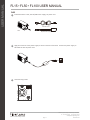
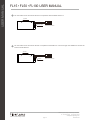
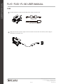
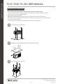
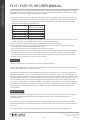
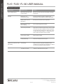
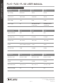
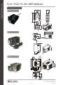
USER MANUAL
FL15 • FL50 • FL100 USER MANUAL
PRODUCT OVERVIEW
The FL15, FL50 and FL100 are LED luminaries designed for use with fiber optics for illumination purposes. This
FiberLamp line can be used with both end-emitting and side-emitting fiber optics made of glass or plastic.
Each luminaire employs the densely packed array of high-powered LEDs, the DiCon Lighting Dense Matrix™ LED, to
deliver intense light into fiber. The FL15, FL50 and FL100 are high brightness white luminaries that are focused on
illumination quality, delivering a full spectrum of light with high CRI.
HARDWARE AND SET-UP
FL15
1
Included hardware: FL15.
2
Apply input cord to 90-264V AC.
3
Set the power switch to the “ON” position to turn on the light.
ON/OFF Switch
www.FiberLamp.com
page 1
1689 Regatta Blvd, Richmond, CA 94804
t 510.620.5200 f 510.620.4102
[email protected]
5870054 A1
USER MANUAL
FL15 • FL50 • FL100 USER MANUAL
FL50
1
Included hardware: FL50, 24V DC/65W Power supply, AC power cord.
AC Power Cord
FL50
AC/DC Power Supply
2
Apply DC connector of the power supply to the DC connector of the FL50. Connect the power supply to
100-240V AC with the power cord.
3
0-10V dimming model.
Sink
+ Sink
+ 10V Source
24VDC/2.1A
www.FiberLamp.com
page 2
1689 Regatta Blvd, Richmond, CA 94804
t 510.620.5200 f 510.620.4102
[email protected]
5870054 A1
USER MANUAL
FL15 • FL50 • FL100 USER MANUAL
4
For connection to Current Source Dimmer in compliance with IEC 60929 Annex E.2.
Top View
Sink
+ Sink
+ 10V Source
V
+ V
Short to +Sink
5
Current Source Dimmer
For connection to Current Source dimmer in compliance with ANSI E1.3. Use wires larger than 24AWG to connect the
FL50 to a 0-10V dimmer.
Top View
Sink
+ Sink
+ 10V Source
V
+ V
Left open
www.FiberLamp.com
Current Source Dimmer
page 3
1689 Regatta Blvd, Richmond, CA 94804
t 510.620.5200 f 510.620.4102
[email protected]
5870054 A1
USER MANUAL
FL15 • FL50 • FL100 USER MANUAL
FL100
1
Included hardware: FL100, 24V DC/120W power supply, AC power cord.
AC Power Cord
FL100
2
24V DC/120W Power Supply
Apply DC connector of power supply to the DC connector of the FL100. Connect the power supply to
100-240V AC with power cord.
www.FiberLamp.com
page 4
1689 Regatta Blvd, Richmond, CA 94804
t 510.620.5200 f 510.620.4102
[email protected]
5870054 A1
USER MANUAL
FL15 • FL50 • FL100 USER MANUAL
INSTALLATION / MOUNTING
Before installing, take the following precautions when selecting a suitable location:
- Install in a well ventilated area (refer to Airflow requirements in Technical Specifications section).
- Make sure the area is free of dust and debris.
- Keep vents free from obstruction.
- Make sure to consider space for installing the power supply used with the FL50 and FL100.
- When using multiple fanned FiberLamps, make sure that they are installed such that no FiberLamp will
intake the exhaust of another.
- Fanned FiberLamps should not be installed with the exhaust vent facing down.
FL15 Use size #8 screws for mounting.
FL50 Use M4 x 0.7 screws through a surface to the bottom of the FL50.
FL100 Use size #8 screws for mounting.
www.FiberLamp.com
page 5
1689 Regatta Blvd, Richmond, CA 94804
t 510.620.5200 f 510.620.4102
[email protected]
5870054 A1
USER MANUAL
FL15 • FL50 • FL100 USER MANUAL
The light output ports of the FL15, FL50 and FL100 fixtures have fixed inner diameters. The outer diameter of the
large core fiber or fiber bundle common end ferrule of the fibers to be used in an installation must be equal to the
inner diameter of each lamp, with a tolerance of -0.25mm.
To install a large core fiber or fiber bundle common end with an outer diameter within the tolerance of the fixture
inner diameter, simply insert the fiber as far back into the light output port as possible, then secure it to the fixture
with the set screw supplied on the output port.
To insert a large core fiber into any FiberLamp:
Large core fiber with ferrule:
For fiber bundle common end with ferrule:
Note: If installing a fiber bundle common end, make
sure that the fiber bundle is properly terminated to a
ferrule as in the following instructions.
If the large core fiber or fiber bundle common end does not match the inner diameters of the fixture, within the
given tolerance, then a ferrule of the appropriate size must be used. For the FL50 and FL100, there are ferrules
available that can accommodate any large core fiber or fiber bundle called the ACS30-xx or ACS33-xx.
www.FiberLamp.com
page 6
1689 Regatta Blvd, Richmond, CA 94804
t 510.620.5200 f 510.620.4102
[email protected]
5870054 A1
USER MANUAL
FL15 • FL50 • FL100 USER MANUAL
When using a ferrule, it is important that the fibers within it are properly terminated. For glass fiber, it is always
suggested to have the fiber manufacturer terminate the fiber into a common end ferrule. To properly terminate
plastic fiber in a ferrule, the suggested procedure is as follows:
a. Obtain a ferrule that has an outer diameter that matches the inner diameter of fixtures light output port. The
ferrule must also have an inner diameter that is appropriately sized given the outer diameter of the large core
fiber or fiber bundle. Refer to the table below for recommendations on what model ACS should be used for
different size fiber and fiber bundle diameters.
Ferrule
ACS30-06/ ACS33-06
ACS30-10/ ACS33-10
ACS30-13/ ACS33-13
ACS30-18/ACS33-18
ACS30-22/ACS33-22
Suggested quantity of
0.75mm diameter fiber
50-180
125-250
250-500
450-750
650-1,200
b. If fiber bundle has an outer casing, remove enough of it such that it does not get inserted into the ferrule with
the fiber. Take care not to damage the fibers while removing the outer casing.
c. Insert the fibers into the ferrule with all fibers protruding past the end of the ferrule.
d. Secure the fibers to the ferrule. This can be done using epoxy if not using an ACS. If using an ACS, tighten
the compression nut over the fiber bundle outer casing.
e. Heat a hot knife so that it is hot enough to melt, but not burn the fiber.
f. Apply the blade of the hot knife onto the the the fibers at the end of the ferrule to be inserted into the fixture,
and slowly but firmly apply pressure on the fibers. Make sure that the knife is applied at an angle such that
the broad side of the knife does not touch freshly cut fiber ends. Allow the heat of the knife to cut the fibers.
Ease the pressure on the fibers as the cut comes to an end.
DIMMING
The FL15 is designed for on/off purposes only and has no dimming control.
The FL50 and FL100 are built standard with a dimming knob. Turn the knob counter clockwise to dim, and clockwise to enhance the brightness of the light source.
The FL50 can be ordered with a 0-10V analog dimming interface for remote electronic dimming, in place of the
physical dimming knob. There are 3 terminals for this interface: +10V source, + sink, - sink. As mentioned in the
Hardware and Set-up section, the FL50 can be dimmed using any 0-10V analog dimmer that is in compliance with
IEC 60929 Annex E.2 or ANSI E1.3. When installed correctly, the dimmer will apply a 0-10V potential to the + sink
terminal, relative to the - sink terminal. The brightness of the light will correspond to the voltage, where 10V
corresponds to 100% brightness and 0V corresponds to 0% brightness. DC voltage is sensitive to electromagnetic
disturbance and long distance. Shielding is recommended for electromagnetic disturbance protection, however
using a twisted pair of 24 AWG wire or larger is sufficient. The wire can extend up to 500ft, but only 200ft is
recommended.
MAINTENANCE
The FL15, FL50 and FL100 are virtually maintenance free. Technical modification of the light source is expressly
forbidden and will void the warranty on the lamp. Repairs must be carried out by the manufacturer or
authorized persons.
To ensure that the light source is always operating in optimal condition, the air intake and exhaust should be
checked and cleaned on a regular basis (frequency of this depends upon the amount of dust in the area around
the fixture).
Excess dust should be removed by wiping with cloth, vacuum cleaner or blowing with compressed air.
www.FiberLamp.com
page 7
1689 Regatta Blvd, Richmond, CA 94804
t 510.620.5200 f 510.620.4102
[email protected]
5870054 A1
USER MANUAL
FL15 • FL50 • FL100 USER MANUAL
TROUBLESHOOTING
Observation
Possible Cause
Solution
Only red light shows
Light output port dust cap
is still installed
Remove the dust cap and reinstall fiber into light
output port.
No light
Fiberlamp is not
connected to power
Connect Fiberlamp to power, following the
instructions in the Hardware and Set-up section.
Power switch is in the
off position
Set the power switch to the on position
Dimming knob is set to
lowest setting
Turn the dimming knob clockwise
Thermal trip activated
Light will turn off if the FiberLamp is too hot. Make
sure there is proper ventilation to the installation
site and that the temperature is within the recommended operating conditions. The light will turn
back on after the FiberLamp has cooled.
Faulty power supply
Renew power supply
Faulty Fiberlamp
Return to manufacturer for repair
Overheating
Make sure there is proper ventilation to the
installation site and that the temperature is within
the recommended operating conditions.
Fan does not work
Return to manufacturer for repair
Light turns on, but turns off
periodically
www.FiberLamp.com
Page 8
1689 Regatta Blvd, Richmond, CA 94804
t 510.620.5200 f 510.620.4102
[email protected]
5870054 A1
USER MANUAL
FL15 • FL50 • FL100 USER MANUAL
TECHNICAL SPECIFICATIONS
Electrical
FL15
FL50
FL100
Input Voltage
90-264V AC
24V DC
24V DC
Input Current
450 mA Max
2.08 A Max
5A Max
Power Rating
15 W
50 W
120 W
Power Supply
NA
24V DC, 2.08A output
100-240V AC input
UL listed LPS
24V DC, 5A output
100-240V AC input
UL listed LPS
Environmental
FL15
FL50
FL100
Ingress Protection
IP20
IP20
IP20
Operating Temp
0° to 40°C
0° to 40°C
0° to 40°C
Storage Temp
-40° to 70°C
-40° to 70°C
-40° to 70°C
Airflow
Open ventilation required
13 cfm
30 cfm
Acoustic Noise
0 dBA
13.8 dBA
19 dBA
Mechanical
FL15
FL50
FL100
Material / Finish
Aluminum / Black
Aluminum / Black
Aluminum / Silver
Weight
1.8 lbs
1.25 lbs
2.45 lbs
Outer Dimensions
5.6” x 3.5” x 2”
5.9” x 2.6” x 3”
7.9” x 4.7” x 3.4”
Input Cord Length
6 ft
6 ft
6 ft
www.FiberLamp.com
Page 9
1689 Regatta Blvd, Richmond, CA 94804
t 510.620.5200 f 510.620.4102
[email protected]
5870054 A1
MECHANICAL DRAWING
2.0”
3.0”
FL15
1.0”
3.8”
5.6”
5.0 m
m
5.6”
3.5”
3.5”
30 mm
2.0”
2.0”
10
mm
FL50
5.9”
5.3”
2.6”
44
m
m
3.0”
.0
m
m
1.5”
30
USER MANUAL
FL15 • FL50 • FL100 USER MANUAL
0.9”
4-M4 x 0.7 x 8.0 DP
MOUTING HOLES
2.6”
5.9”
0.5”
5.0”
3.0”
0.3”
0.3”
2.0”
4xM4x0.7x8.00P
MOUNTING HOLE
FAR SIDE
FL100
4x10.4x4.4
MOUNTING HOLE
0.2”
4.7”
1.1”
7.9”
4” 7.9”
5.91” 5.51”
AIR FLOW
3.4”
0.3”
3.2”
0.4”
3.8”
4.7”
1.9”
3.4”
1.7”
www.FiberLamp.com
Page 10
1689 Regatta Blvd, Richmond, CA 94804
t 510.620.5200 f 510.620.4102
[email protected]
5870054 A1


![LL STAGE 6-06D W - [2013.07.04]](http://vs1.manualzilla.com/store/data/005734810_1-c52217095191e9110aa67fdeef6b5f60-150x150.png)