Download Lightscape User Manual PDF
Transcript
®
User Manual
August 2006
®
This user manual is designed to help the operators and owners of Lightscape® products
use, troubleshoot, and utilize all of the product’s potential.
Customers seeking additional help not mentioned in this user manual should contact
Main Light Industries. Please use the “Contact Us” page in this manual or your
Lightscape® contact.
Table of Contents
Lightscape® Manual
Getting Started
Diagram / Zone & Circuit Configurations
Warnings and Maintenance
Handling the Curtain / Folding Instructions
Contact Us
Fiber Optic Fixture Manual
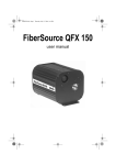
Martin FiberSource QFX150
Controller Manual
Elation DMX Operator 192 or American DJ DMX Operator
Flame Certificates
Main Light Industries, Inc.
402 Meco Drive
Wilmington, DE 19804
Telephone: 302.998.8017
Fax: 302.998.8019
3
5
7
9
10
11
37
®
User Manual
Lightscape Manual
®
Revision: August 2006
Getting Started
1. Before hanging and connecting any of the system, visually check for any damage
from shipping.
2. Remove curtain from case by removing lid and flipping case on end.
If there are multiple curtains, remove top curtains by pulling the curtains
off a non-latched side of the case to prevent damage.
Properly remove the curtain from the case
3. Tie drapery onto support system.
Secure drapery tightly
Main Light Industries, Inc.
Telephone: 302.998.8017
Website: http://www.mainlight.com
Lightscape Manual: Getting Started
Page: 3
®
User Manual
Revision: August 2006
4. Place fiber optic fixtures where fiber optic bundles end from drapery. Check
dip switches on all fiber optic fixtures for standalone usage or controller usage.
Connect the fiber optic bundles to the fiber optic fixtures.
Note: Refer to the fiber optic fixture’s manual for correct dip switch settings.
5. Plug in all power for the fiber optic fixtures into proper power sources.
6. Place the controller where the fixtures will be controlled from and plug in power
from proper power source.
7. Ensure all units in system are turned on.
Last Steps Apply to Controlled Fiber Optic Fixtures ONLY
8. Connect all XLR data cable.
Note: The data should create a chain starting from the controller. Refer to the
diagram for more information.
9. Set the controller to strike the fiber optic fixture lamps.
The fiber optic curtain should be lit and ready to use
Main Light Industries, Inc.
Telephone: 302.998.8017
Website: http://www.mainlight.com
Lightscape Manual: Getting Started
Page: 4
User Manual
®
Revision: August 2006
Lightscape® Fiber Optic Curtain Diagrams
Lightscape®
System Schematic Diagram
�
�
�
�
�
Lightscape®
Fiber Optic Curtain
�
�
�
�
�
�
�
�
�
�
�
�
�
�
�
�
�
�
�
�
�
�
�
�
�
�
Lightscape®
Fiber Optic Curtain
� �
� �
�
�
�
�
�
�
�
X
Fiber
Optic
Fixture
O
Fiber
Optic
Fixture
X
Fiber
Optic
Fixture
O
Fiber
Optic
Fixture
DMX
In | Out
DMX
In | Out
DMX
In | Out
DMX
In | Out
�
�
�
�
DMX Out
Controller
Data Cable
Main Light Industries, Inc.
Telephone: 302.998.8017
Website: http://www.mainlight.com
Fiber Optic Bundle
Lightscape Manual: Diagrams
Page: 5
User Manual
®
Revision: August 2006
Lightscape®
Zone and Circuit Configurations
1 Zone / 1 Circuit
x
x
x
x
x
x
x
x
x
o
o
x
x
o x
x
o
o
o
x
x
o
x
x
o
x
x
o
x
x
o
x
o
x
o
o
x
x
x
x
o
o
o
x
o x
x
x
o
x
x
o
o
o
x
x
2 Zone / 3 Circuit
o x
o
o
o
o
o
x
x
x
x
o
o
x
o
x
x
x
o
1 Zone / 3 Circuit
o
o
x
x
x
x
o
o x
o
o
x
o
x
x
2 Zone / 2 Circuit
o
x
x
x
o
o
o
x
x
x
x
1 Zone / 2 Circuit
x
o
x
x
x
x
x
x
x
x
x
x
x
x
x
x
x
x
x
x
x
x
x
x
x
x
x
x
x
x
2 Zone / 1 Circuit
x
o
o
x
o x
o
x
x
o
o
o
x
x
x
o
x
o x
o
x
x
o
x
o
o
x
Fiber Optic Bundle
Main Light Industries, Inc.
Telephone: 302.998.8017
Website: http://www.mainlight.com
Lightscape Manual: Diagrams
Page: 6
®
User Manual
Revision: August 2006
Warnings and Maintenance
Warnings:
- Ensure there are no sharp objects near the curtain.
- The curtain has flame retardant capabilities however; measures should be take to
keep flames and hot objects away from the curtain.
- Keep the fiber optic fixtures in a well-ventilated area with proper power to prevent
overheating and damage.
Repairing the Curtain or Fixtures:
- ALL major repairs should be done through your Lightscape® dealer.
- Do not attempt to repair the fiber optic fixtures (with the exception of changing the
lamp). Consult the fixture user manual in this document or contact technical support
with any questions.
- Any damage to the face of the curtain should be repaired professionally unless the
damage needs immediate attention and may increase.
- Minor repairs to the back liner of the curtain should be fixed using a black gaffing
tape. Tape a few inches longer than the rip and about three tape widths wide.
Main Light Industries, Inc.
Lightscape Manual: Warnings and Maintenance
Telephone: 302.998.8017
Page: 7
Website: http://www.mainlight.com
®
User Manual
Revision: August 2006
Keeping the Curtain Clean:
- Always check the area that the curtain will be used in for any spilled liquids, dirt, or
other materials that may damage the curtain.
- As with all curtains, Lightscape® curtains will absorb dirt and liquids. Extra care
should be considered to ensure the area is as clean as possible.
- Fluids used in special effects machines (such as bubble or snow machines) will
sometimes leave a residue on the curtain. If possible, avoid effects that will go
directly towards the curtain.
Cleaning the Curtain:
- Do not clean the curtain using chemicals or soaking the curtain with any liquid.
Soaking the curtain will reduce the flame retardant capabilities of the curtain.
- Occasionally, the curtain may need to be brushed with a broom to remove lint
or dust. This is done by sweeping from the top of the curtain towards the bottom.
(Sweep in the direction of the natural fabric nap.)
- If absolutely necessary, small stains may be removed by hand using water only
with a damp rag. Pat the area with a dry rag and brush the nap back into place.
Main Light Industries, Inc.
Lightscape Manual: Warnings and Maintenance
Telephone: 302.998.8017
Page: 8
Website: http://www.mainlight.com
®
User Manual
Revision: August 2006
Handling the Curtain
Always fold the curtain face in. This is very important to protect the fibers
from damage.
Always grab the curtain by the edges. Damage to the fiber strands inside
the curtain will occur if the curtain is grabbed or pulled roughly on inside area
of the curtain.
Never drag a curtain by its fiber optic bundles.
Larger curtains should be handled by at least two people due to their size
and weight.
Folding Instructions
Start Folding Widthwise:
Begin by laying out the curtain and folding the curtain widthwise in half by bringing
the edge opposite of the fiber optic bundles towards the tubes, being sure only
to pull the curtain by the edges. Carefully continue to fold the curtain in halves
widthwise until it is ready to be folded lengthwise (about three to five feet wide).
Finish Folding Lengthwise:
Beginning at the end opposite of the fiber optic bundles, create a rectangle roughly
three feet in size with the first fold. Use this rectangle to continue folding the curtain
until there is one fold left. Gently place the fiber optic bundles on top of the last
section and fold the rest of the curtain on top.
Main Light Industries, Inc.
Telephone: 302.998.8017
Website: http://www.mainlight.com
Lightscape Manual: Handling and Folding
Page: 9
®
User Manual
Revision: August 2006
Contact Us
We are here to help you, contact us if you need any assistance.
Main Light Industries, Inc.
402 Meco Drive
Wilmington, DE 19804
Telephone: 302.998.8017
Fax: 302.998.8019
Main Light Website:
http://www.mainlight.com/
After Hours Technical Support:
Please call the main phone number and a technical emergency phone number will
be provided.
Main Light Industries, Inc.
Telephone: 302.998.8017
Website: http://www.mainlight.com
Lightscape Manual: Contact Us
Page: 10
35000079B.fm Page 1 Thursday, December 9, 1999 11:47 AM
FiberSource QFX 150
user manual
35000079B.fm Page 2 Thursday, December 9, 1999 11:47 AM
1
cooling fan
2
lamp access
cover screw
3
adaptor set screw
4
cable socket
5
mounting flange
6
DIP-switch
7
data sockets
8
AC input & main
fuse
©1999 Martin Professional A/S, Denmark.
All rights reserved. No part of this manual may be
reproduced, in any form or by any means, without
permission in writing from Martin Professional A/S,
Denmark.
Printed in Denmark.
P/N 35000079, Rev. B
35000079B.fm Page 3 Thursday, December 9, 1999 11:47 AM
INTRODUCTION . . . . . . . . . . . . . . . . . . . . . . . . . . . . . . . . . . . . . . . . . 4
LAMP . . . . . . . . . . . . . . . . . . . . . . . . . . . . . . . . . . . . . . . . . . . . . . . . 6
AC POWER . . . . . . . . . . . . . . . . . . . . . . . . . . . . . . . . . . . . . . . . . . . 7
INSTALLATION . . . . . . . . . . . . . . . . . . . . . . . . . . . . . . . . . . . . . . . . . 9
FIBER OPTIC CABLE . . . . . . . . . . . . . . . . . . . . . . . . . . . . . . . . . . . . 11
CONTROLLER OPERATION . . . . . . . . . . . . . . . . . . . . . . . . . . . . . . . . 12
STAND-ALONE OPERATION . . . . . . . . . . . . . . . . . . . . . . . . . . . . . . . 16
MASTER/SLAVE OPERATION . . . . . . . . . . . . . . . . . . . . . . . . . . . . . . 18
BASIC SERVICE . . . . . . . . . . . . . . . . . . . . . . . . . . . . . . . . . . . . . . . 19
TROUBLESHOOTING . . . . . . . . . . . . . . . . . . . . . . . . . . . . . . . . . . . . 22
DMX PROTOCOL . . . . . . . . . . . . . . . . . . . . . . . . . . . . . . . . . . . . . . 23
SPECIFICATIONS . . . . . . . . . . . . . . . . . . . . . . . . . . . . . . . . . . . . . . 25
ACCESSORIES . . . . . . . . . . . . . . . . . . . . . . . . . . . . . . . . . . . . . . . . 28
3
35000079B.fm Page 4 Thursday, December 9, 1999 11:47 AM
1
INTRODUCTION
Thank you for selecting the Martin FiberSource QFX 150. This fiber optic lighting
fixture uses a long-life 150 watt discharge lamp and provides 4 colors plus white,
full-range dimming, and a variable-speed twinkle effect. It operates with DMX-512
controllers, in stand-alone mode, and in master/slave configuration.
SAFETY INFORMATION
Warning!
This product is for professional use only. It is not for household use.
This product presents risks of lethal or severe injury due. Read this manual before
powering or installing the fixture, follow the safety precautions listed below and
observe all warnings in this manual and on the fixture. If you have questions about
how to operate the fixture safely, please contact your Martin dealer or call the
Martin 24-hour service hotline.
To prot ect yoursel f and ot hers fr om electr ic shock
• Disconnect the fixture from power before removing or installing the lamp, fuses, or
any part, and when not in use.
• Always ground (earth) the fixture electrically.
• Use only a source of power that complies with local building and electrical codes
and has both overload and ground-fault protection.
• Do not expose the fixture to rain or moisture.
• Refer all service to a qualified technician.
To prot ect yoursel f and ot hers fr om UV radiat ion and lamp
explosion
• Do not operate the fixture without a fiber optic cable inserted.
• When replacing the lamp, allow the fixture to cool for at least 5 minutes before
opening. Protect your hands and eyes with gloves and safety glasses.
• Never look at a lamp while it is lit.
• Replace the lamp when it becomes defective or worn out, or before usage exceeds
110 percent of the rated average life.
4
Introduction
35000079B.fm Page 5 Thursday, December 9, 1999 11:47 AM
To prot ect yourself and ot hers f rom burns and f ire
• Never attempt to bypass the thermostatic switch or fuses. Always replace defective
fuses with ones of the specified type and rating.
• Keep all combustible materials (for example fabric, wood, paper) at least 0.1 meters
(4 inches) away from the fixture. Keep flammable materials well away from the
fixture.
• Provide a minimum clearance of 0.1 meters (4 inches) around fans and air vents.
• Allow the fixture to cool before handling.
• Do not modify the fixture or install other than genuine Martin parts.
• Do not operate the fixture if the ambient temperature (Ta) exceeds 40° C (104° F).
To prot ect yourself and ot hers f rom injury due t o falls
•
When suspending the fixture above ground level, verify that the structure can hold
at least 10 times the weight of all installed devices.
•
Verify that all external covers and rigging hardware are securely fastened and use an
approved means of secondary attachment such as a safety cable.
•
Block access below the work area whenever installing or removing the fixture.
UNPACKING
The packing material is carefully designed to protect the fixture during shipment always use it to transport the fixture.
The FiberSource QFX 150 comes with:
• Osram HQI-R 150 W lamp
• 3 m power cable w/ 3-pin IEC female cord cap
• 4 dichroic color filters
• user manual
Introduction
5
35000079B.fm Page 6 Thursday, December 9, 1999 11:47 AM
2
LAMP
The FiberSource QFX 150 is designed for use with the Osram HQI-R 150 lamp. Do
not install any other type of lamp.
Warning!
Disconnect the fixture from power and allow it to cool before
opening.
Important! Turn the lamp so that the arc is horizontal.
To inst all or posit ion the lamp
1 Remove the 4 lamp access
cover screws and pull off the
access
c o v e r,
which
is
indicated by the arrow on the
rear panel.
2 To remove the lamp, place a
hand under it and pull it out. Do
not lift by the ceramic base
alone. Squeeze the sides of the
lamp plug and pull it out.
3 To position the lamp, turn it so the wires,
where they exit the lamp base, point
towards the ground when the fixture is
installed . This puts the arc in its ideal
burning position.
4 To install a lamp, plug in the connector
and then place the reflector rim in the
slot. Gently press the lamp between the
Turn lamp so wires
point towards
ground and arc is
horizontal.
Align long edge of
diffuser prisms
with arc.
springs until it snaps into place.
5 Remove and turn the diffusion filter 90°, if necessary, so the long sides of the
prisms align with the arc.
6 Check the power setting as described in the next section before replacing the
lamp access cover.
6
Lamp
35000079B.fm Page 7 Thursday, December 9, 1999 11:47 AM
3
AC POWER
The FiberSource QFX 150 has 10 switch-selectable power supply settings. Always
use the setting that is closest to the local AC supply.
Warning!
For protection from electric shock, the fixture must be grounded
(earthed). The power supply shall have overload and groundfault protection.
Important! Install fuse and verify that power supply settings match local
AC supply before use.
To check or change the volt age
set t ing
1 Disconnect the fixture from power.
Remove the lamp access cover.
setting closest to the AC voltage. Use
the higher setting if the voltage is
60Hz
50Hz
2 Set the 5-position switch to the
halfw ay b etw een 2 settin gs. Fo r
ex a m p l e , u s e t h e 2 3 0 V s e t t i n g
i n s te a d o f th e 2 1 0 V s et ti n g fo r
operation with 220 V power.
3 Set the 2-position switch to the AC
250 V
230 V
frequency (50 / 60 Hz).
4 Replace the cover and apply a new
power settin g label to the serial
210 V
100 V
number label.
120 V
AC power
7
35000079B.fm Page 8 Thursday, December 9, 1999 11:47 AM
To inst all the main f use
Fuses are provided for 100 - 130 V and 200 - 250 V operation. Use only the fuse
specified for the operating voltage.
1 Locate the bag containing the fuse for your AC voltage. Insert the fuse in the
fuse holder. The holder may be packed with the other fuse.
2 Remove the label covering the mains input socket.
3 Insert the fuse holder in the empty slot in the mains input socket. See also “To
replace the main fuse” on page 20.
To inst all a plug on t he power cable
The power cable must be fitted with a grounding-type cord cap that fits your power
distribution system. Consult an electrician if you have any doubts about proper
installation.
Important! Verify that the feed cables are undamaged and rated for the
current requirements of all connected devices before use.
•
Following the cord cap manufacturer’s instructions, connect the yellow and
green wire to ground (earth), the brown wire to live, and the blue wire to neutral.
The table below shows some pin identification schemes.
Wire
8
Pin
Marking
Screw color
brown
live
“L”
yellow or brass
blue
neutral
“N”
silver
yellow/green
ground
AC power
green
35000079B.fm Page 9 Thursday, December 9, 1999 11:47 AM
4
INSTALLATION
The FiberSource QFX 150 can be fastened directly through the 4 rubber washers in
the mounting flanges, or hung with 2 rigging clamps (not included) fastened
through the 13 mm holes.
INSTALLATION REQUIREMENTS
For optimum performance and ease of service, install the fixture such that
• The long axis is horizontal as
shown in A to right. This
positions the lamp electrodes
for maximum lamp life. Do not
install as shown in B.
• The minimum clearance around
the fans and air vents at both
ends is 10 cm (4 in.) and
circulation is adequate keep the
air around the fixture at 40° C
(104° F) or below.
• The DIP-switch is accessible and there is room to insert cables.
• The lamp access panel can be removed.
• All safety requirements are met.
To i nstall t he FiberSour ce QFX 150
Warning!
Always use a secure means of secondary attachment when
hanging the fixture with clamps.
1 Verify that the fasteners or clamps can bear 10 times the fixture’s weight. Verify
that the structure can support 10 times the weight of all installed fixtures,
clamps, cables, auxiliary equipment, etc.
2 Block access below the work area.
3 If fastening directly, place a metal washer over each rubber washer. The metal
washer must be as wide as the rubber washer, or wider, to insure a secure hold.
Fasten with 4 suitable fasteners 4 - 5 mm (5/32 - 3/16 in.) in diameter.
Installation
9
35000079B.fm Page 10 Thursday, December 9, 1999 11:47 AM
4 If clamping, bolt the clamps securely to the flanges with grade 8.8 (minimum)
M12 bolts and lock nuts, or as recommended by the clamp manufacturer,
through the 13 mm holes. Install a safety cable that can hold at least 10 times
the weight of the fixture through one of the small holes and around the truss or
pipe. Remove a rubber washer if necessary to thread the safety cable.
5 Verify that the fixture is located at least 0.1 meters (4 in.) from any combustible
materials. Verify that the clearance around the fan and air vents is at least 0.1
meters (4 in.). Verify that there are no flammable materials nearby.
10
Installation
35000079B.fm Page 11 Thursday, December 9, 1999 11:47 AM
FIBER OPTIC CABLE
5
The FiberSource male adaptor for 50 - 300 strand cables, P/N 91611016 (not
included), is tapered to fit fiber optic cables 8.3 - 19.3 mm (5/16 - 3/4 in.) in
diameter. With cables over 8.3 mm in diameter, the adaptor must be shortened for
proper fit and maximum light output. Please follow the instructions included with
the fiber adaptor.
CABLE CONNECTION
The following guidelines provide a starting point for estimating your needs. Light
transmission through fiber-optic cable depends on its quality and results will vary
depending on the type of cable used.
SIDE-EMITTING CABLE
With 1 fixture, best results are had when the fiber optic cable is 10 m (33 ft.) or
shorter. The length may be increased to 15 m (50 ft.) by looping the cable and
illuminating both ends. With 2 fixtures, one at each end of the cable, lengths up to
30 m (100 ft.) can be achieved.
END-EMITTING CABLE
Light output decreases with length: keep the cable as short as possible. The
maximum recommended length is 25 meters. Cut the light emitting end of the fibers
with a sharp knife for maximum output.
To i nstall f iber opt ic cable
1 Install the cable in the fiber adaptor according to the instructions packaged
with the adaptor.
2 Insert the adaptor fully into the fiber optic cable socket.
3 Tighten the set screw with a 2 mm (5/64 in.) Allen wrench.
Fiber optic cable
11
35000079B.fm Page 12 Thursday, December 9, 1999 11:47 AM
6
CONTROLLER OPERATION
This FiberSource QFX 150 may be operated with any DMX-512 protocol
controller.
DATA CONNECTION
A reliable data connection begins with the right cable. Standard microphone cable
cannot transmit DMX data reliably over long runs. For best results, use cable
specifically designed for RS-485 applications. Your Martin dealer can supply high
quality cable in various lengths.
The FiberSource QFX 150’s data sockets are wired pin 1 to ground, pin 2 to signal (cold), and pin 3 to signal + (hot). This is the standard pin assignment for DMX
devices.
One or more adaptor cables may be required to connect the fixture to the controller
and other devices because many devices have 5-pin connectors and others may have
reversed signal polarity, that is, pin 2 hot and pin 3 cold.
5-pin to 3-pin
Adaptor
3-pin to 5-pin
Adaptor
3-pin to 3-pin
Phase-Reversing
Adaptor
Male
Female
Male
Female
Male
Female
1
2
3
4
5
1
2
3
1
2
3
1
2
3
4
5
1
2
3
1
2
3
P/N 11820005
P/N 11820004
P/N 11820006
To connect t he dat a link
1 Connect a data cable to the controller’s data output. If controller has a 5-pin
output, use a 5-pin male to 3-pin female adaptor cable (P/N 11820005).
2 Lead the data cable from the controller to the first fixture and plug the cable
into the data input.
12
Controller operation
35000079B.fm Page 13 Thursday, December 9, 1999 11:47 AM
3 Connect the output of the fixture closest to the
c o n t ro l l e r t o t h e i n p u t o f t h e n ex t f i x t u r e . I f
Male
Termination Plug
connecting to a fixture with reversed-polarity (pin 3
cold), insert a phase-reversing cable between the two
Male XLR
fixtures.
4 Continue connecting fixtures output to input. Up to
32 devices may be connected on a serial link.
1
2
3
120
5 Terminate the link by inserting a male termination
plug (P/N 91613017) into the data output of the last
f i x t u re . A t e r m i n a ti o n p l u g i s s i m p ly a n X L R
P/N 91613017
connector with a 120 ohm, 0.25 W resistor soldered
across pins 2 and 3.
ADDRESS SELECTION
A control address must be set using the DIP-switch on the rear panel. The control
address, also known as the start channel, is the first channel used to receive
instructions from the controller. The FiberSource QFX 150 uses 5 DMX channels.
Each fixture must be assigned its own address and non-overlapping control
channels for individual control. Two FiberSource QFX 150s may share the same
address, but they will respond identically and individual control will not be
possible.
Important! Disconnect the fixture from power before changing the DIPswitch setting. Changes take effect after the fixture has been
turned off and back on.
To set t he address
1 Select an address for the fixture between 1 and 508 on your controller.
2 Look up the DIP-switch setting for the address on page 14.
3 Disconnect the fixture from power.
4 Set pins 1 through 9 to the ON (1) or OFF (0) position as listed in the table.
5 Set pin 10 to the OFF position.
Controller operation
13
35000079B.fm Page 14 Thursday, December 9, 1999 11:47 AM
DIP-SWITCH ADDRESS TABLE
Find the address in the table below. Read the settings for pins 1 - 5 to the left and
read the settings for pins 6 - 9 above the address. “0” means OFF and “1” means
ON.
Important! Pin 10 must be OFF for controller operation.
DIP-Switch Setting
#1
0
1
0
1
0
1
0
1
0
1
0
1
0
1
0
1
0
1
0
1
0
1
0
1
0
1
0
1
0
1
0
1
14
0 = OFF
1 = ON
#2 #3 #4
0
0
0
0
0
0
1
0
0
1
0
0
0
1
0
0
1
0
1
1
0
1
1
0
0
0
1
0
0
1
1
0
1
1
0
1
0
1
1
0
1
1
1
1
1
1
1
1
0
0
0
0
0
0
1
0
0
1
0
0
0
1
0
0
1
0
1
1
0
1
1
0
0
0
1
0
0
1
1
0
1
1
0
1
0
1
1
0
1
1
1
1
1
1
1
1
#5
0
0
0
0
0
0
0
0
0
0
0
0
0
0
0
0
1
1
1
1
1
1
1
1
1
1
1
1
1
1
1
1
#9
#8
#7
#6
0
0
0
0
0
0
0
1
0
0
1
0
0
0
1
1
0
1
0
0
0
1
0
1
0
1
1
0
0
1
1
1
1
0
0
0
1
0
0
1
1
0
1
0
1
0
1
1
1
1
0
0
1
1
0
1
1
1
1
0
1
1
1
1
1
2
3
4
5
6
7
8
9
10
11
12
13
14
15
16
17
18
19
20
21
22
23
24
25
26
27
28
29
30
31
32
33
34
35
36
37
38
39
40
41
42
43
44
45
46
47
48
49
50
51
52
53
54
55
56
57
58
59
60
61
62
63
64
65
66
67
68
69
70
71
72
73
74
75
76
77
78
79
80
81
82
83
84
85
86
87
88
89
90
91
92
93
94
95
96
97
98
99
100
101
102
103
104
105
106
107
108
109
110
111
112
113
114
115
116
117
118
119
120
121
122
123
124
125
126
127
128
129
130
131
132
133
134
135
136
137
138
139
140
141
142
143
144
145
146
147
148
149
150
151
152
153
154
155
156
157
158
159
160
161
162
163
164
165
166
167
168
169
170
171
172
173
174
175
176
177
178
179
180
181
182
183
184
185
186
187
188
189
190
191
192
193
194
195
196
197
198
199
200
201
202
203
204
205
206
207
208
209
210
211
212
213
214
215
216
217
218
219
220
221
222
223
224
225
226
227
228
229
230
231
232
233
234
235
236
237
238
239
240
241
242
243
244
245
246
247
248
249
250
251
252
253
254
255
256
257
258
259
260
261
262
263
264
265
266
267
268
269
270
271
272
273
274
275
276
277
278
279
280
281
282
283
284
285
286
287
288
289
290
291
292
293
294
295
296
297
298
299
300
301
302
303
304
305
306
307
308
309
310
311
312
313
314
315
316
317
318
319
320
321
322
323
324
325
326
327
328
329
330
331
332
333
334
335
336
337
338
339
340
341
342
343
344
345
346
347
348
349
350
351
352
353
354
355
356
357
358
359
360
361
362
363
364
365
366
367
368
369
370
371
372
373
374
375
376
377
378
379
380
381
382
383
384
385
386
387
388
389
390
391
392
393
394
395
396
397
398
399
400
401
402
403
404
405
406
407
408
409
410
411
412
413
414
415
416
417
418
419
420
421
422
423
424
425
426
427
428
429
430
431
432
433
434
435
436
437
438
439
440
441
442
443
444
445
446
447
448
449
450
451
452
453
454
455
456
457
458
459
460
461
462
463
464
465
466
467
468
469
470
471
472
473
474
475
476
477
478
479
480
481
482
483
484
485
486
487
488
489
490
491
492
493
494
495
496
497
498
499
500
501
502
503
504
505
506
507
508
509
510
511
Controller operation
35000079B.fm Page 15 Thursday, December 9, 1999 11:47 AM
CONTROLLABLE EFFECTS
LAMP POWER AND RESET
The lamp on command is on channel 1, the address channel. When set up for
controller operation, the lamp remains off until a lamp-on command is sent.
A peak of electric current many times the operating current is drawn briefly when
striking a lamp. Striking many discharge lamps at once may cause a voltage drop
that prevents lamps from striking or trips circuit breakers. When striking multiple
fixtures, space lamp on commands at 5 second intervals.
The lamp can be turned off as well, but then it must be allowed to cool for several
minutes before it can be turned back on. To prevent accidental lamp off commands,
this command only works when the dimmer is closed (ch. 2 < 3) and the twinkle
effect is rotating slowly CCW (ch. 4 > 252). If a hot lamp does not strike, send the
lamp off command and wait several minutes before trying again.
All effects reset to their home positions when the fixture is powered up. There is
also a reset command on channel 1. To prevent accidental resets, the command must
be sent for 5 seconds.
DIMMER
The intensity of the light is controlled from full-off to full-on on channel 2.
COLOR
The color wheel is controlled on channel 3. You can program split-color effects with
continuous scroll, stick to full color positions using stepped scroll, and rotate the
wheel continuously. The speed at which colors fade from one position to another
can be controlled on channel 5, the speed channel.
TWINKLE
The speed and direction of the twinkle effect is controlled on channel 4. When
stopped, the effect wheel returns to its home position where there is a removable
section. The light output can be made more uniform if the twinkle effect is not used
by removing this section.
FADE SPEED
Channel 5 controls the speed of the color wheel, allowing you to achieve variable
fades on controllers without cross-faders. If your controller has cross-faders, and
you use them, then set channel 5 to 0 (tracking), for best results.
Controller operation
15
35000079B.fm Page 16 Thursday, December 9, 1999 11:47 AM
STAND-ALONE OPERATION
7
CONTROL OPTIONS
The FiberSource QFX 150 can be operated without a controller in stand-alone
mode. This mode provides various combinations of color and twinkle effect that are
selected using DIP-switch pins 1 - 7.
The twinkle effect may by set to off, slow, medium, or fast using DIP-switch pins 1
and 2. If the twinkle effect is not required, a section of the effect wheel can be
removed to increase the uniformity of the output: refer to “To remove or replace the
twinkle wheel section” on page 19.
The speed at which the color wheel moves from one color to the next may be set to
snap, slow, medium, or fast using DIP-switch pins 3 and 4. This setting has no effect
if white or color 1 is selected.
The color or colors are selected using DIP-switch pins 5, 6, and 7. You can select
white, color 1 (position 1), a range of colors, and continuous rotation. If continuous
color wheel rotation is selected, then the color change speed must be slow, medium,
or fast.
If a range of colors is selected, the color wheel holds at position 1 for 1 second,
moves to position 2 at the selected change speed, holds for 1 second, and so on.
When the last position is reached, the color wheel reverses direction. Colors can be
arranged in any order as described under “To change color filters” on page 19.
To set stand- al one behavi or
1 Disconnect the fixture from power.
2 Set DIP-switch pins 1 - 7 on or off as shown in the table below to achieve the
desired combination of effects.
3 Set pins 8 and 9 to off. Set pin 10 to on.
4 Apply power to the fixture.
The option setting will take effect and the lamp will automatically strike. Note,
however, that a hot lamp must cool for several minutes before it can be restruck. If
the lamp does not strike, disconnect the fixture from power for several minutes to
reduce strain on the starter while the lamp cools.
16
Stand-alone operation
35000079B.fm Page 17 Thursday, December 9, 1999 11:47 AM
pin 8
pin 9
pin 10
0
1
slow twinkle
1
0
0
0
1
medium twinkle
0
1
0
0
1
fast twinkle
1
1
pin 7
0
pin 6
0
Effect
pin 5
0
pin 4
pin 2
no twinkle
0 = OFF
1 = ON
pin 3
pin 1
Important! DIP-switch pin 10 must be ON for stand-alone operation.
Setting
0
0
1
snap color change
0
0
0
0
1
slow color change
1
0
0
0
1
medium color change
0
1
0
0
1
fast color change
1
1
0
0
1
white
0
0
0
0
0
1
color 1
1
0
0
0
0
1
color 1 - 2
0
1
0
0
0
1
color 1 - 4
1
1
0
0
0
1
color 1 - 6
0
0
1
0
0
1
color 1 - 8
1
0
1
0
0
1
color 1 - 9
0
1
1
0
0
1
continuous rotation*
1
1
1
0
0
1
* Continuous rotation is not available when snap color change is selected.
Stand-alone operation
17
35000079B.fm Page 18 Thursday, December 9, 1999 11:47 AM
8
MASTER/SLAVE OPERATION
Several FiberSource QFX 150s may be connected together for synchronous
operation without a controller. They are connected together and one, the master, is
set up in stand-alone mode and sends control instructions to the others. Up to 32
fixtures can be can be connected and operated this way.
Important
Verify that all slave fixtures are set as described. Damage can
be caused if there is more than 1 device (master fixture or
controller) sending control signals on the serial data link.
To connect and set f ixt ur es for mast er/slave operation
1 Disconnect all fixtures from power.
2 Plug a 3-pin XLR data cable into the OUT socket of the first fixture and the IN
socket of the next fixture.
3 Continue connecting fixtures output to input. Up to 32 FiberSource QFX 150s
may be connected.
4 Terminate the data link on
both ends. Insert a female
termination
plug
(P/N
91613018) into the IN socket
of the first fixture. Insert a
Male
Termination Plug
Female
Termination Plug
Male XLR
Female XLR
1
2
3
male termination plug (P/N
91613017) into the OUT
socket of the last fixture. A
120
1
2
3
120
termination plug is an XLR
connector with a 120 ohm,
0.25 W resistor so ldered
P/N 91613017
P/N 91613018
across pins 2 and 3.
5 Select any one fixture to be the master. Set the desired stand-alone options
using the master’s DIP-switch as described on page 16.
6 On all other fixtures (slaves), set DIP-switch pin 1 to the ON position; set all
other DIP-switch pins to the OFF position.
7 Apply power to the fixtures.
18
Master/slave operation
35000079B.fm Page 19 Thursday, December 9, 1999 11:47 AM
9
BASIC SERVICE
The FiberSource QFX 150 requires simple routine maintenance. The maintenance
schedule depends heavily on the operating environment; please consult a Martin
service technician for recommendations.
Any service procedure not described here should be referred to a qualified
technician.
Warning!
Disconnect the fixture from power before removing any cover.
Important! Excessive dust, grease, and smoke fluid buildup degrades
performance and causes overheating and damage to the fixture
that is not covered by the warranty.
To change col or fil ters
1 Disconnect the fixture from power. Remove the lamp access cover.
2 Turn the color wheel by hand until the desired filter is accessible.
3 Using a soft cloth or gloves, gently tilt the outside edge of the filter back
towards the lamp to unlock. Remove filter.
4 To place a filter in the wheel, insert the plastic holder between the spring clip
with the protruding tab facing forwards until it snaps into place.
5 Replace the lamp access cover before applying power.
To remove or replace the twinkle wheel secti on
The twinkle wheel has a removable section for uniform light output when the effect
is not used.
1 Disconnect the fixture from power. Remove the lamp access cover.
2 Turn the twinkle wheel by hand until the removable section is aligned with the
cable socket. Turn the color wheel so that the open position is aligned with the
cable socket.
3 Support the twinkle wheel with one hand and unlock the removable section by
pulling the outside edge back towards the lamp. Grasp the section and pull it
up and out.
4 To replace the section, turn the wheel to the open position and slide the section
between the wheel and the spring clip, with the heads of the screws towards
Basic service
19
35000079B.fm Page 20 Thursday, December 9, 1999 11:47 AM
the cable socket. Center the section and then support the wheel with a finger
from the front as you press the 2 screw heads through the wheel.
5 Replace the lamp access cover before applying power.
To clean opti cal component s
Use care when cleaning optical components. The surface of the color filters is
fragile and small scratches may be visible.
1 Disconnect the fixture from power and allow it to cool completely. Remove the
lamp access cover.
2 Blow or vacuum away loose dust. Remove residues from filters with a soft cloth
or cotton swabs wetted with isopropyl alcohol. Regular glass cleaner may also
be used, but no residues may remain.
3 Rinse with distilled water. Mixing the water with a small amount of wetting
agent such as Kodak Photoflo will help prevent streaking and spotting.
4 Dry with a clean, soft and lint-free cloth or blow dry with compressed air.
To clean t he f an and air vents
To maintain adequate cooling, dust must be cleaned from the fan and air vents
periodically.
1 Disconnect the fixture from power.
2 Remove dust and dirt from the fan blades and vent grills using a soft brush,
cotton swab, vacuum, or compressed air.
To replace the main f use
1 Unplug the mains cable from the input socket. Pry open the fuse holder as
shown.
2 Remove the defective fuse and replace it with one of the same type and rating.
3 Replace the fuse holder in the mains input socket.
20
Basic service
35000079B.fm Page 21 Thursday, December 9, 1999 11:47 AM
To replace t he secondary fuse
1 Disconnect the fixture from power.
2 Remove one screw by the DIP-switch and one screw by the data IN socket.
3 Pull the circuit board assembly out until you can access the fuse, which is
located behind the data IN socket.
4 Remove the defective fuse and replace it with one of the same type and rating.
5 Replace the circuit board assembly before applying power.
Basic service
21
35000079B.fm Page 22 Thursday, December 9, 1999 11:47 AM
10
TROUBLESHOOTING
Problem
Fixture is completely dead.
Fixture resets correctly but does
not respond to the controller.
Fixture fails to reset correctly.
No light.
Lamp cuts out intermittently or
burns out too quickly.
22
Probable cause(s)
Remedy
No power to fixture.
Check that power is switched on
and cables are plugged in.
Primary fuse blown.
Replace fuse.
Secondary fuse blown.
Replace fuse.
The controller is not connected.
Connect controller.
Reversed data signal polarity.
Install a phase-reversing cable
between the controller and the
fixture.
Bad data link connection
Inspect connections and cables.
Repair or replace damaged
cables.
Data link not terminated.
Insert termination plug in output
of the last fixture on the link.
Incorrect address setting.
Check DIP-switch settings.
One of the fixtures is
transmitting as a master or is
defective.
Bypass one fixture at a time
until normal operation is
regained: unplug both cables
from fixture and connect them
directly together. Contact
Martin technician for service.
An effect requires mechanical
adjustment.
Contact Martin technician for
service.
Lamp too hot to strike.
Allow lamp to cool.
Power settings do not match AC
supply.
Check AC setting.
Defective lamp.
Replace lamp.
Fixture is too hot.
Allow fixture to cool.
Power settings do not match AC
supply.
Check settings.
Defective fan.
Contact Martin technician for
service.
Troubleshooting
35000079B.fm Page 23 Thursday, December 9, 1999 11:47 AM
A
DMX PROTOCOL
Channel
1
2
3
4
5
Value
Percent
Function
0 - 89
90 - 119
120 - 149
150 - 199
200 - 249
250 - 255
0 - 35
35 - 46
47 - 58
59 - 78
78 - 98
98 - 100
Reset and lamp power
No function
Reset (time > 5 sec.)
No function
Lamp on
No function
Lamp off (w/ Ch. 2 < 3 & Ch. 4 > 252)
0 - 255
0 - 100
Dimmer
Closed to Open
0 - 144
0
16
32
48
64
80
96
112
128
144
0 - 56
0
6
12
18
25
31
37
44
50
56
Color Wheel
Continuous scroll
Open
Color 1 (blue 108)
Color 2 (green 206)
Color 3 (yellow 603)
Color 4 (red 308)
Color 5 (-)
Color 6 (-)
Color 7 (-)
Color 8 (-)
Color 9 (-)
145 - 185
145 - 148
149 - 152
153 - 156
157 - 160
161 - 164
165 - 168
169 - 172
173 - 176
177 - 180
181 - 185
57 - 72
57 - 58
58 - 59
60 - 61
61 - 63
63 - 64
65 - 66
66 - 67
68 - 69
69 - 70
71 - 72
Stepped scroll
Color 9 (-)
Color 8 (-)
Color 7 (-)
Color 6 (-)
Color 5 (-)
Color 4 (red 308)
Color 3 (yellow 603)
Color 2 (green 206)
Color 1 (blue 108)
Open
186 - 220
221 - 255
73 - 86
87 - 100
Continuous rotation
CW, fast to slow
CCW, slow to fast
0-1
2 - 125
126 - 131
132 - 255
0
0 - 49
49 - 51
52 - 100
Twinkle Wheel
Stop/Open
CW, slow to fast
Stop
CCW, fast to slow
0-2
3-5
6 - 255
0
1
2 - 100
Color Speed
Tracking (speed function off)
Fast speed with shortcut enabled
Fast to slow, shortcut disabled
DMX protocol
23
FiberSource QFX150 DMX Protocol
Start code = 0
25
L
I
G
H
T
50
1
2
X
4
20
P
D
5
C1
C2
C3
C4
50
175
200
225
LAMP ON
250
LO
NO FUNCTION
A F
M F
P
40
C5
75
open
50
60
70
80
STEPPED COLOR SCROLL
C6
C7
100
C8
125
CONTINUOUS ROTATION
C 9 9 8 7 6 5 4 3 2 1 0 fast
150
90
CW
175
200
slow slow
CCW
225
fast
250
TWINKLE
S slow
CW
20
fast stop fast
30
40
CCW
50
60
slow
70
80
90
COLOR SPEED
T Tf
fast
slow
25
35000079B.fm Page 24 Thursday, December 9, 1999 11:47 AM
30
CONTINUOUS COLOR SCROLL
white
10
S
150
NO FUNCTION
DIMMER
25
F
125
RESET
hold 5 seconds
C
3
100
closed
10
L
R
75
NO FUNCTION
Implemented from software version 1.0
50
75
* Close dimmer and set channel 4 to full to enable lamp off.
T = tracking mode (speed function off)
Tf = tracking mode with shortcuts
100
125
150
175
200
225
250
35000079B.fm Page 25 Thursday, December 9, 1999 11:47 AM
B
S PECIFICATIONS
PHYSICAL
Length: . . . . . . . . . . . . . . . . . . . . . . . . . . . . . . . . . . . . . . . . . . . . . . . . . . . . 330 mm (13.0 in)
Width: . . . . . . . . . . . . . . . . . . . . . . . . . . . . . . . . . . . . . . . . . . . . . . . . . . . . . . 213 mm (8.4 in)
Height: . . . . . . . . . . . . . . . . . . . . . . . . . . . . . . . . . . . . . . . . . . . . . . . . . . . . . 199 mm (7.8 in)
Weight: . . . . . . . . . . . . . . . . . . . . . . . . . . . . . . . . . . . . . . . . . . . . . . . . . . . . . . . . 10.4kg (lbs)
SOURCE
Osram HQI-R 150 (included): . . . . . . . . . . . . . . . . . . . . . . . . . . . . . 150 W, 6000 hr., 4200K
CONTROL
Control options: . . . . . . . . . . . . . . . . . . . . . . . . . . . . . .DMX-512, stand-alone, master/slave
DMX channels: . . . . . . . . . . . . . . . . . . . . . . . . . . . . . . . . . . . . . . . . . . . . . . . . . . . . . . . . . . 5
Data I/O: . . . . . . . . . . . . . . . . . locking 3-pin XLR, pin 1 shield, pin 2 cold (-), pin 3 hot (+)
Recommended cable: . . . 24 AWG (min.), low capacitance, 85-150 Ω shielded twisted pair
INSTALLATION
Orientation: . . . . . . . . . . . . . . . . . . . . . . . . . . . . . . . . . . . . . . . . . . . . . . . . . . . . . . horizontal
Minimum distance to combustible materials: . . . . . . . . . . . . . . . . . . . . . . . . . . .0.1 m (4 in)
Minimum clearance around fan and air vents: . . . . . . . . . . . . . . . . . . . . . . . . . . .0.1 m (4 in)
AC SUPPLY
Power supply options: . . . . . . . . . . . 100/120/210/230/250 V, 50/60 Hz (switch-selectable)
Maximum power and current: . . . . . . . . . . . . . 205W, 1.9A @ 120V; 195W, 1.0A @ 230V
FUSES
Primary fuse: . . . . . . . . . . . . . . . . . . . . . . . . . . . . T 3.15 A, high I2t, 250 V, P/N 05020013
Secondary fuse: . . . . . . . . . . . . . . . . . . . . . . . . . . . . . . . . . . T 2.0 A, 250 V, P/N 05020009
CONSTRUCTION
Housing: . . . . . . . . . . . . . . . . . . . . . . . . . . . . . . . . . . . . . . . . . . . . . sheet steel and aluminum
Finish: . . . . . . . . . . . . . . . . . . . . . . . . . . . . . . . . . . . . . . black, electrostatic powder coating
Protection factor: . . . . . . . . . . . . . . . . . . . . . . . . . . . . . . . . . . . . . . . . . . . . . . . . . . . . . . IP 20
Specifications
25
35000079B.fm Page 26 Thursday, December 9, 1999 11:47 AM
C
A CCESSORIES
Male adaptor for 50 - 300 strand cables with installation materials: . . . . . . .P/N 91611016
G-clamp: . . . . . . . . . . . . . . . . . . . . . . . . . . . . . . . . . . . . . . . . . . . . . . . . . . . . .P/N 91602003
Half-coupler clamp: . . . . . . . . . . . . . . . . . . . . . . . . . . . . . . . . . . . . . . . . . . . . .P/N 91602005
Accessory color filter, blue 111: . . . . . . . . . . . . . . . . . . . . . . . . . . . . . . . . . . .P/N 62327015
Accessory color filter, blue 101: . . . . . . . . . . . . . . . . . . . . . . . . . . . . . . . . . . .P/N 62327016
Accessory color filter, cyan 401: . . . . . . . . . . . . . . . . . . . . . . . . . . . . . . . . . . .P/N 62327017
Accessory color filter, green 202: . . . . . . . . . . . . . . . . . . . . . . . . . . . . . . . . . .P/N 62327018
Accessory color filter, yellow 604: . . . . . . . . . . . . . . . . . . . . . . . . . . . . . . . . .P/N 62327019
Accessory color filter, red 301: . . . . . . . . . . . . . . . . . . . . . . . . . . . . . . . . . . . .P/N 62327021
Accessory color filter, pink 312: . . . . . . . . . . . . . . . . . . . . . . . . . . . . . . . . . . .P/N 62327022
Accessory color filter, magenta 507: . . . . . . . . . . . . . . . . . . . . . . . . . . . . . . . .P/N 62327023
Accessory color filter, purple 502: . . . . . . . . . . . . . . . . . . . . . . . . . . . . . . . . .P/N 62327025
Accessory color filter, green 204: . . . . . . . . . . . . . . . . . . . . . . . . . . . . . . . . . .P/N 62327034
Accessory color filter, orange 306: . . . . . . . . . . . . . . . . . . . . . . . . . . . . . . . . .P/N 62327035
26
Accessories
User Instructions
Elation Professional R
4295 Charter Street
Los Angeles CA. 90058
www.elationlighting.com
Table of Contents
Welcome ..........................................................................................1
General Instruction..........................................................................2
Warnings.........................................................................................2
Cautions......................................................................................... 2
Control and Functions.................................................................... 3
Front View...................................................................................3
Rear View................................................................................... 4
Operation Guide.............................................................................. 5
Scene operation............................................................................. 5
Chase operation............................................................................. 7
Bank copy & Fixture copy...............................................................9
PAN/TILT Setting.......................................................................... 10
Fade Time..................................................................................... 11
MIDI Control.................................................................................. 11
Data Sending............................................................................... 12
Data Receiving............................................................................. 12
Memory Stick................................................................................12
Technical Specifications ..............................................................13
Welcome
Main features as below:
- 8 dimming faders & total 192 DMX channels
- Speed fader & Fade Time fader
- 30 banks x 8 programmable scenes
- 12 programmable chases, each chase can record up to 240 steps
- Fade time setting & Pan/Tilt setting
- Manual control gets first priority
- Built-in microphone or line input for audio triggering
- MIDI control upon banks, chases and blackout
- External step Control & Fog machine control
- 7-segment LED display
- USB connector for both DJ work light and data backup
- Scan Master II with joystick module or with jog wheel module available
as your desire
Joystick module
Jog wheel module
Every effort has been made to design dependability, reliability and comfort
into each unit. New products are being designed constantly to meet the needs
of both entertainment and the lighting industry. We welcome your comments
about our product and services.
It is both a privilege and a pleasure serving you.
1
General Instruction
This is a professional lighting controller with a total of 192 DMX output channels.
30 banks of programmable scenes (one bank contains 8 scenes) and 12 chases
with up to 240 steps each are provided for your application. Speed, Fade Time &
Pan/Tilt adjustment are also provided by this unit. USB connector can be used to
realize data backup and DJ work light.
To optimize performance of this product, please read the instructions carefully
to familiarize yourself with the basic operations.
Warnings
This unit is intended for indoor use only.
Do not make any inflammable liquids, water or metal objects enter the unit.
To reduce the risk of fire or electric shock, do not expose the unit to rain or
high levels of moisture.
No user serviceable parts inside, do not dismantle the unit by yourself.
Repairs must be done by qualified personnel.
Please do not allow children to play and tamper with this product.
Cautions
When unpacking, please check the unit is not damaged. Should something
wrong happen to this product, contact the local dealer immediately.
All rights reserved. No part of the manual included with this product may be
reproduced, transmitted, transcribed or translated into any language in any
form, by any means, without authorized permission.
Notice:
Specifications and improvements in the design of this product and this
manual are subject to change without any prior notice.
2
Control and Functions
Front View
9
10
FIXTURES
SCENES
11
12
OPERATOR 192
Step/time
BANK
2
7
8
1
3
9
4
10
5
11
2
3
4
6
5
7
10
1
10
2
10
3
10
4
10
5
10
6
10
7
10
8
8
9
8
10
8
11
8
12
8
13
8
14
8
15
8
16
USB
PORT
Auto Trigger
0.1S
Ready
FOG MACHINE
Bank
Chase Scene
8
Heating
Audio Trigger
Blackout
Step
PROG
1
30S
1
2
3
4
5
6
7
8
9
10
11
12
Music/Bkc
Midi/Rec
Auto/Del
Tap/Disp
Blackout
CHASE
1
13
Channel 1/8
Channel 9/16
6
12
Program
6
6
6
6
6
6
6
6
4
4
4
4
4
4
4
4
2
2
2
2
2
2
2
2
PAN
14
15~20
TILT
Assign
0
0
0
0
0
0
0
0
Reverse
Channel
Bank
MODE
0
10Min
Speed
Fade Time
FINE
2
3
4 5
6
7
8
1. Fixture buttons(1~12):
Used to select relevant fixture.
2. Channel faders(1~8):
Used to control the dimming output of each corresponding channel.
3. Channel Bank button:
To switch between Ch1~8 and Ch9~16.
4. Speed fader:
To adjust the speed level (0.1 second ~10 minutes).
5. Fade Time fader:
To adjust the fade time (0~30seconds).
6. FINE button:
In the "FINE" mode, you can adjust the Pan/Tilt finely.
7. MODE button:
This is a multi-functional button, please see the operation for details.
8. Pan/Tilt joystick:
Used to adjust the Pan/Tilt level.
9. Scene buttons (1~8): to select a scene.
10. LED-display:
This LED-display shows you relevant information depending on your operation.
11. Bank Up/Down button:
To select a bank or step (see operation guide for details).
3
Control and Functions
12. USB socket:
It's for data backup or USB light connection.
13. Fog-machine button:
It's for fog-machine control.
14. Chase button(1~12): to select a chase.
15. Program button :
Used to enter/exit the programing mode.
16. Music/Bkc button:
Used to enter audio control or to realize Bank copy.
17. Midi/Rec button:
It's for MIDI setting and/or for scene/chase recording.
18. Audio/Del button :
Used to enter the AUTO mode, or to delete a scene/chase.
19. Tap/Disp button:
It is a multi-functional button, please see the operation for details.
20. Black-out button:
This will allow the operator to instantly stop all channels' output (press this
button again to reactivate the output).
Rear View
DC input:
9V-12VDC, 500mA Min
AUDIO
1
Line Input 0.1V-1Vp-p
DB-9
EXT STEP CONTROL
MIDI IN
FOG MACHINE
2
3
4
5
1 = Ground
2 = Data 3 = Data +
DMX OUT
6
DC IN
POWER
7
Made in PRC
8
1. Label.
2. Audio input: to input audio data (0.1V-1Vp-p).
3. DB-9 connector: to connect an external step controller.
4. MIDI IN: to receive MIDI data.
5. Fog machine connector: to connect with the fog machine.
6. DMX OUT: 3 Pin DMX output socket (female).
7. DC INPUT: to input main power (DC 9V~15V, 500mA Min).
8. Power switch: to turn on/off the main power.
4
Operation Guide
Scene Operation
When powered on, this unit will be firstly in the Manual control mode, and all channel
outputs are in black-out state (the Blackout LED flashes at the display window). You
can also press the Blackout button to enable the channel output.
Press and hold down the Program button for about 2 seconds till the PROG LED flashes,
this means you have entered the programing mode. Press and hold down the Program
button for about 2 seconds again (till the PROG LED goes out) to exit from the Programing mode.
To record a scene
(1) Enter the Programing mode as the above told you.
(2) Press a Fixture button, its LED will be lit.
(3) Use the channel faders to set a scene (You can use the Channel Bank button to
select between Ch1~8 and Ch9~16 as your desire).
(4) Then press the REC button to record the scene that you have set.
(5) Select a bank (01~30).
(6) Select a Scene button (1~8) in this bank and press it, all LEDs flash briefly, this
means you setting has been saved.
(7) Set the other scene(s) in the same way as your desire.
(8) After finishing your settings, you can press and hold down the Program button for
about 2 seconds (till the PROG LED goes out) to exit from the Programing mode.
Note: The recorded scene can be reedited; if you reedit a scene and save it, the old
scene will be replaced by the new one.
To edit a scene
(1) Enter the Programing mode.
(2) Select your desired being edited scene in a bank.
(3) Press a Fixture button (its LED lights up), and then set a new scene.
(4) Press Midi/Rec button, and then press the selected scene button (all LEDs flash
briefly, that means your setting has been saved).
5
Operation Guide
To copy a scene
(1)
(2)
(3)
(4)
Enter the Programing mode.
Select your desired being copied scene in a bank.
Press Midi/Rec button.
Press your selected Scene button in the relevant bank, all LEDs flash briefly, that
means your copy operating has been saved.
To delete a scene
(1) Enter the Programing mode.
(2) Select a scene to be deleted.
(3) Press and hold down the DEL button, and at the same time, tap your selected
Scene button, all LEDs will flash briefly, that means the scene has been deleted.
To delete all the scenes
Before turning on the power, you press and hold down the Program button and the Bank
Down button, and then turn on the power at the same time, all LEDs flash briefly, this just
means all the scenes have already been deleted.
Scene Playback
1. Manual trigger:
(1) When powered on, this unit will be firstly in the Manual control mode, and all channel
outputs are in black-out state (the Blackout LED flashes at the display window).
(2) Tap the Blackout button (Blackout LED goes out) to enable the channel output.
(3) Select your desired scene to be replayed, tap this scene button to enable the scene
(Tap this scene button again to disable the scene).
2. Auto trigger:
(1) Tap the AUTO button, the Auto Trigger LED will light up at the display window, this
indicates you that you are now in the Auto trigger mode.
(2) Tap Bank Up/Down button to select desired bank (0~30).
(3) You can use the Speed fader (or Tap/disp button) and the Fade Time fader to adjust
the running state.
(4) Tap the Auto button again(Auto Trigger LED goes out) to exit from the Auto mode.
Note: You can tap the Tap/Disp button twice to create an interval running rate.
6
Operation Guide
3. Audio trigger:
(1) Tap the Music/Bkc button, the Audio Trigger LED will light up at the display window,
this indicates you that you are now in the Audio trigger mode.
(2) Tap Bank Up/Down button to select desired bank (the scenes in the bank will run
sensitively by the Audio signal through the built-in microphone).
(3) Tap the Audio button again(Audio Trigger LED goes out) to exit from the Audio mode.
Chase Operation
This product has 12 programmable chases, each chase can record up to 240 scenes/
steps. Please see the below instructions for Chase setting.
To record a chase
(1) Enter the Programing mode.
(2) Press a Chase button, its LED will be lit.
(3) Select a scene which you want to record into the chase as the first step.
(4) Press the REC button, all LEDs will flash briefly, that means your operation has
been saved.
(5) Record more scenes into the chase as your desire till finish your settings. Up to
240 scenes (steps) can be recorded in a chase.
To record a bank of scenes into a chase
(1) Enter the Programing mode.
(2) Select a Chase to be edited.
(3) Select a bank which you want to record into the chase.
(4) Tap the Music/Bkc button, and then tap the Midi/Rec button, all LEDs will flash briefly,
that means the selected bank has been recorded into this chase.
To add a step into a chase
(1) Enter the Programing mode.
(2) Select a Chase to be edited.
(3) Tap the Tap/disp button, the Step LED appears and the display window shows you the
current step.
(4) Tap the Up/Down button to select the step behind which you want to add a step.
7
Operation Guide
(5) Set a scene(step), and then tap the Rec button, the display will show you the follwing step.
(6) You tap the Tap/disp button, and then tap the Rec button again, all LEDs flash briefly,
this means your operation has been saved.
You can add more scenes(steps) into a chase in the same way as the above.
To delete a scene (step) from a chase
(1) Enter the Programing mode.
(2) Select a chase to be edited.
(3) Tap the Tap/disp button, the Step LED appears and the display window shows you
the current step.
(4) Tap the Up/Down button to select the step to be deleted.
(5) Tap the DEL button to delete this step, all LEDs flash briefly, and the display will
show you the ahead step.
To delete a chase
(1) Enter the Programing mode.
(2) Select a chase to be deleted.
(3) Press and hold down the DEL button, and at the same time, tap your selected chase
button, all LEDs will flash briefly, that means the chase has been deleted.
To delete all the chases
Before turning on the power, you press and hold down the DEL button and the Bank
Down button, and then turn on the power at the same time, all LEDs flash briefly, this
just means all the chases have been deleted.
Chase Playback
1. Manual trigger:
(1) When powered on, this unit will be firstly in the Manual control mode, and all channel
outputs are in black-out state (the Blackout LED flashes at the display window).
(2) Tap the Blackout button (Blackout LED goes out) to enable the channel output.
(3) Tap your selected Chase button, its LED will be lit. Then use the Fade Time fader to
adjust the running state.
(4) Tap the Up/Down button to run the chase step by step.
8
Operation Guide
2. Auto trigger:
(1) Tap the AUTO button, the Auto Trigger LED will light up at the display window, this
indicates you that you are now in the Auto trigger mode.
(2) Select your desired chase and press related chase button, its LED will flash.
(3) You can then use the Speed fader (or Tap/disp button) and the Fade Time fader to
adjust the running state.
(4) Tap the Auto button again (Auto Trigger LED goes out) to exit from the Auto mode.
Note: You can simultaneously run more scenes as your desire, and the enabled scenes
will run by your operating sequence.
3. Audio trigger:
(1) Tap the Music/Bkc button, the Audio Trigger LED will light up at the display window,
this indicates you that you are now in the Audio trigger mode.
(2) Select your desired chase and press related chase button, its LED will flash. The chase
will run sensitively by the audio signal through the built-in microphone.
(3) Tap the Audio button again(Audio Trigger LED goes out) to exit from the Audio mode.
Bank copy & Fixture copy
Bank copy
1. Enter the Programming mode.
2. Use the Bank Up/Down buttons to select the bank to be copied.
3. Tap the Midi/Rec button, and then select the bank into which you want to copy.
4. Tap the Music/Bkc button, all LEDs flash briefly, this means your operation has been
saved. (You can copy the other bank in the same way.)
Fixture copy
1. Enter the Programming mode.
2. Press your selected Fixture button, its LED will be lit.
3. Set your desired channel output.
4. Press and hold down your selected Fixture button, and then tap the Fixture button into
which you want to copy to finish your Fixture copy.
5. You can see the related information through the connected DMX receiver.
9
Operation Guide
PAN/TILT Setting
"Assign"
1. Enter the Programming mode.
2. Press and hold down the MODE button, and then tap the FINE button at the same
time, the "Assign" LED will be lit.
3. Tap the Up/Down button to select PAN or TILT.
4. Tap your selected Fixture button.
6. You can press and hold down the MODE button, and then tap relevant scene button
to set the Pan/Tilt channel (all LEDs will flash briefly).
"Reverse"
1. Enter the Programming mode.
2. When the "Assign" LED is lit, you press and hold down the MODE button, and then tap
the FINE button at the same time, the "Reverse" LED will be lit.
3. Set the Pan/Tilt channel in the same way as above. After your settings, press and hold
down the MODE button, and then tap the FINE button at the same time to exit.
Delete Pan/Tilt channel
1. When in "Assign" or "Reverse" operating mode, press the related Fixture button.
2. Press and hold down the MODE button, and then tap the DEL button to delete the
Pan/Tilt channel.
Delete all Pan/Tilt channels
Before turning on the power, you press and hold down the DEL button and the MODE
button, and then turn on the power at the same time, all LEDs flash briefly, this means
means all Pan/Tilt channels have been deleted.
10
Operation Guide
Fade Time
1. Press and hold down MODE button, and then tap the Tap/disp button, the display
may show you "only"; Repeat this operation when "only" appears, the display will
show you "All".
2. The "only" or "ALL" display will go out automatically within almost 3 seconds.
"ALL" means that All channels run by the fade time.
"Only" means that only the preset PAN/TILT channels run by the fade time.
MIDI Control
Set MIDI channel
1. Press and hold down the Midi button for about 2 seconds, the display may show you
like "In:01", this means the current Midi channel is "01". You can use Up/Down button
to set the Midi channel from 01 to 16 as your desire.
2. Then, press and hold down the Midi button for about 2 seconds to save your setting,
all the LEDs flash briefly indicating your operation has been saved.
3. Press Blackout button to exit.
MIDI Control :
This unit can receive MIDI data to realize MIDI control upon Bank1~15,Chase1~6
and the Blackout function.
11
MIDI Note
00~07
08~15
... ...
Control
Bank 1
Bank 2
... ...
Function
Turn on/off Bank 1
Turn on/off Bank 2
... ...
112~119
120
121
122
123
124
125
126
Bank 15
Chase 1
Chase 2
Chase 3
Chase 4
Chase 5
Chase 6
Blackout
Turn on/off Bank 15
Turn on/off Chase 1
Turn on/off Chase 2
Turn on/off Chase 3
Turn on/off Chase 4
Turn on/off Chase 5
Turn on/off Chase 6
Enable/disable Blackout
Operation Guide
Data Sending
Before data sending, make sure the connections between this unit and the connected
DMX receiver are well done.
1. Before turning on the power, press and hold down the Fixture2 button, the Fixture3
button and the Scene1 button; Then turn on the power, the display will flickeringly
show you "Read" (ready). This means the unit is ready to send data.
2. After the above operation, you press and hold down the Scene7 button and Scene8
button to send the data, the LED-display will show you "OUT" till the data sending is
finished (You can also tap the Scene1 button during data sending to come back and
resend the data).
Data Receiving
Before data receiving, make sure the connections between this unit and the connected
DMX receiver are well done.
1. Before turning on the power, press and hold down the Fixture2 button, the Fixture3
button and the Scene2 button; Then turn on the power, the display will flickeringly
show you "Read" (ready). This means the unit is ready to receive data.
2. The LED-display shows you "Rece" (receive) during data receiving. (You can also tap
the Scene1 button during data sending to come back and resend the data).
Memory stick
You can also use a compact memory stick (sold separately) for convenient data backup
and transfer.
Memory stick (sold separately)
12
Technical Specifications
Power Input ...........................................................................DC9~15V, 500mA
Internal Fuse...................................................................500mA 250V, 5x20mm
MIDI IN...............................................................................5Pin MIDI connector
DMX OUT.....................................................5Pin/3Pin(female) DMX connector
SOUND INPUT...........................................................................RCA connector
EXT STEP CONTROL...............................................................DB-9 connector
Dimensions ...............................................................................483x135x82mm
Weight(approx.) ........................................................................................2.2 kg
24-004-1685 Rev 1.1
All Rights Reserved!


