1
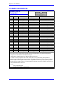
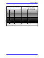
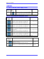
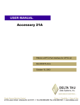
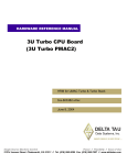
^1 USER MANUAL
^2 OPTION 9L
^3 RS-422 Serial Interface Adapter
^4 4Ax-602315-xUxx
^5 November 1994
Single Source Machine Control
Power // Flexibility // Ease of Use
21314 Lassen Street Chatsworth, CA 91311 // Tel. (818) 998-2095 Fax. (818) 998-7807 // www.deltatau.com
Copyright Information
© 2003 Delta Tau Data Systems, Inc. All rights reserved.
This document is furnished for the customers of Delta Tau Data Systems, Inc. Other uses are
unauthorized without written permission of Delta Tau Data Systems, Inc. Information contained
in this manual may be updated from time-to-time due to product improvements, etc., and may not
conform in every respect to former issues.
To report errors or inconsistencies, call or email:
Delta Tau Data Systems, Inc. Technical Support
Phone: (818) 717-5656
Fax: (818) 998-7807
Email: [email protected]
Website: http://www.deltatau.com
Operating Conditions
All Delta Tau Data Systems, Inc. motion controller products, accessories, and amplifiers contain
static sensitive components that can be damaged by incorrect handling. When installing or
handling Delta Tau Data Systems, Inc. products, avoid contact with highly insulated materials.
Only qualified personnel should be allowed to handle this equipment.
In the case of industrial applications, we expect our products to be protected from hazardous or
conductive materials and/or environments that could cause harm to the controller by damaging
components or causing electrical shorts. When our products are used in an industrial
environment, install them into an industrial electrical cabinet or industrial PC to protect them
from excessive or corrosive moisture, abnormal ambient temperatures, and conductive
materials. If Delta Tau Data Systems, Inc. products are exposed to hazardous or conductive
materials and/or environments, we cannot guarantee their operation.
Option 9L User Manual
Table of Contents
INTRODUCTION ........................................................................................................................................ 1
INSTALLATION ......................................................................................................................................... 3
CONNECTORS............................................................................................................................................ 5
JUMPERS ..................................................................................................................................................... 7
OPERATION................................................................................................................................................ 9
CONNECTOR PINOUTS ......................................................................................................................... 11
JRS422 (26-Pin Connector) ..................................................................................................................... 11
JRS422 (DB-15 Connector) ..................................................................................................................... 12
JUMPERS ................................................................................................................................................... 13
E8: RS232 Converter Power Supply Control.......................................................................................... 13
E9 - E16: Serial Interface Handshake Control ........................................................................................ 13
Table of Contents
i
Option 9L User Manual
ii
Table of Contents
Option 9L User Manual
INTRODUCTION
Option 9L for the PMAC-Lite replaces the standard RS-232 serial communications interface with
an RS-422 interface. It consists of a small piggyback board that sits on top of the PMAC-Lite in
the area of the J4 connector. Because the RS-422 interface uses differential line drivers and
receivers, it permits greater noise immunity and longer cable lengths than RS-232. Because the
drivers are tri-stated, this option permits the PMAC-Lite to be used with other PMAC-Lites or
PMAC-PCs on a single daisy-chained serial cable (which is not possible with the standard RS232 interface).
Introduction
1
Option 9L User Manual
2
Introduction
Option 9L User Manual
INSTALLATION
When Option 9L is ordered with the PMAC-Lite, the option board is installed onto the PMAC at
the factory. If Option 9L is ordered for add-on to an existing PMAC-Lite, it may be possible to
install as a field upgrade.
If IC U33 on the PMAC-Lite is soldered directly into the board and not socketed, it will not be
possible to perform a field upgrade to install the option board. This is true of older versions of
the PMAC-Lite; for these units, the PMAC must be returned to the factory for installation of
Option 9L.
However, if IC U33 on the PMAC-Lite is socketed, a field installation is possible. The
installation is very simple:
1. Remove ICs U33 and U38 from their sockets on the PMAC-Lite. These ICs will not be used
when the Option 9L is installed; store them safely for possible future use.
2. Place the two provided screws through the holes on the PMAC-Lite so that the heads are on
the back (solder) side of the board. Slide the provided spacers over the shafts of the bolts on
the front side of the board.
3. Place the Option 9L board on the PMAC-Lite so that the prongs on the back fit into the
sockets for U33 and U38.
4. Tighten the screws to secure the board.
Installation
3
Option 9L User Manual
4
Installation
Option 9L User Manual
CONNECTORS
Two connectors are provided on the Option 9L. Only one of these connectors may be used at a
time, as selected by Jumper W2.
J1 provides the RS-422 signals on a 26-pin IDC male connector. This is the same connector as
for the RS-422 port on the PMAC-PC. It is designed for a straight-across connection to a DB-25
connector for RS-232 or RS-422 on a host computer.
J2 provides the RS-422 signals on a DB-15 female connector. This connector is designed for
straight-across connection to a DB-15 connector for RS-422 on a Fanuc system.
Connectors
5
Option 9L User Manual
6
Connectors
Option 9L User Manual
JUMPERS
Jumpers E9-E16 on the Option 9L permit the user to exchange, send, and receive lines for both
data and handshaking. However, almost all users will keep the default configuration. When the
Option 9L board is installed, these jumpers take the place of jumpers E9, E10, E13, and E14 on
the PMAC-Lite itself, which are not used.
Jumpers
7
Option 9L User Manual
8
Jumpers
Option 9L User Manual
OPERATION
There is no difference in software operation between a PMAC-Lite with Option-9L and one
without. The software is unaware of the difference in the signal driver voltages.
However, with the Option 9L, it is possible to use PMAC's serial daisy-chain capability on the
PMAC-Lite with software card addressing. To specify which card is active on the daisy-chain,
the host uses the @n command, where “n” is a hexadecimal digit specifying the card number. The
card whose jumpers E40-E43 specify a card number matching “n” will be the active card on the
chain, accepting commands, and capable of responding over the chain.
Operation
9
Option 9L User Manual
10
Operation
Option 9L User Manual
CONNECTOR PINOUTS
JRS422 (26-Pin
Connector)
Front View
Pin #
Symbol
Function
Description
Notes
1
CHASSI
Common
PMAC Common
2
S+5V
Output
+5Vdc Supply
Deactivated by "E8"
3
RDInput
Receive Data
Differential I/O Low True **
4
RD+
Input
Receive Data
Differential I/O High True *
5
SDOutput
Send Data
Differential I/O Low True **
6
SD+
Output
Send Data
Differential I/O High True *
7
CS+
Input
Clear to Send
Differential I/O High True **
8
CSInput
Clear to Send
Differential I/O Low True *
9
RS+
Output
Request to Send
Differential I/O High True **
10
RSOutput
Request to Send
Differential I/O Low True *
11
DTR
Bi-directional
Data Term Ready
Tied to "DSR"
12
INIT/
Input
PMAC Reset
Low is "RESET"
13
GND
Common
PMAC Common
**
14
DSR
Bi-directional
Data Set Ready
Tied to "DTR"
15
SDIOBi-directional
Special Data
Differential I/O Low True
16
SDIO+
Bi-directional
Special Data
Differential I/O High True
17
SCIOBi-directional
Special Control
Differential I/O Low True
18
SCIO+
Bi-directional
Special Control
Differential I/O High True
19
SCKBi-directional
Special Clock
Differential I/O Low True
20
SCK+
Bi-directional
Special Clock
Differential I/O High True
21
SERVOBi-directional
Servo Clock
Differential I/O Low True ***
22
SERVO+
Bi-directional
Servo Clock
Differential I/O High True ***
23
PHASEBi-directional
Phase Clock
Differential I/O Low True ***
24
PHASE+
Bi-directional
Phase Clock
Differential I/O High True ***
25
GND
Common
PMAC Common
26
+5V
Output
+5Vdc Supply
Power Supply Out
The JRS422 connector provides the PMAC with the ability to communicate both in RS422 and RS232.
This connector is also used to daisy chain interconnect multiple PMACs for synchronized operation.
* Required for communications to an RS-422 host port
** Required for communications to an RS-422 or RS-232 host port
*** Output on card @0; input on other cards. These pins are for synchronizing multiple PMACs
together by sharing their phasing and servo clocks. The PMAC designated as card 0 (@0) by its jumpers
E40-E43 outputs its clock signals. Other PMACs designated as cards 1-15 (@1-@F) by their jumpers
E40-E43 take these signals as inputs. If synchronization is desired, these lines should be connected even
if serial communications is not used.
See Also:
Serial Communications
Synchronizing PMAC to other PMACs
Connector Pinouts
11
Option 9L User Manual
JRS422 (DB-15 Connector)
Pin #
Symbol
Function
Description
Notes
1
CHASSI
Common
PMAC Common
2
N.C.
None
No Connect
3
N.C.
None
No Connect
4
N.C.
None
No Connect
5
S+5V
Output
+5VDC Supply
Deactivated by E8
6
RSOutput
Request to Send
Differential I/O Low True *
7
GND
Common
PMAC Common
**
8
CS+
Input
Clear to Send
Differential I/O High True **
9
N.C.
None
No Connect
10
RDInput
Receive Data
Differential I/O Low True **
11
RD+
Input
Receive Data
Differential I/O High True *
12
SDOutput
Send Data
Differential I/O Low True **
13
SD+
Output
Send Data
Differential I/O High True *
14
RS+
Output
Request to Send
Differential I/O High True **
15
CSInput
Clear to Send
Differential I/O Low True *
The JRS422 connector provides the PMAC with the ability to communicate both in RS422 and RS232. It
does not permit the daisy chaining of multiple PMACs.
12
Connector Pinouts
Option 9L User Manual
JUMPERS
E8: RS232 Converter Power Supply Control
E-Point &
Physical
Layout
E8
Physical
Layout
Description
Default
Jump pin 1 to 2 to apply +5V to "J2" pin 2 (JRS422);
this can be used to power optional RS422 to RS232
converter module which requires +5V for operation.
Jumper installed
E9 - E16: Serial Interface Handshake Control
E-Point &
Physical
Layout
E9
E10
E11 E12
E13 E14
E15 E16
Description
Default
Jump, E9-1 to E9-2 to allow 'RD-' to be input on J2-3;
jump E10-1 to E10-2 to allow 'SD-' to be output on J2-5
Jump E9-1 to E10-1 to allow 'RD-' to be output on J2-3;
jump E9-2 to E10-2 to allow 'SD-' to be input on J2-5
E9 1-2 Jumper installed
E10 1-2 Jumper installed
Jump E11-1 to E11-2 to allow 'RD+' to be input on J2-4;
jump E12-1 to E12-2 to allow 'SD+' to be output on J2-6
Jump E11-1 to E12-1 to allow 'RD+' to be output on J2-4;
jump E11-2 to E12-2 to allow 'SD+' to be input on J2-6
E11 1-2 Jumper installed
Jump E13-1 to E13-2 to 1-2 allow CS-' to be input jumper
on J2-7; jump E14-1 to installed E14-2 to allow 'RS-' to be
output on J2-9
Jump E13-1 to E14-1 to allow 'CS-' to be output on J2-7;
jump E14-2 to E14-2 to allow 'RS-' to be input on J2-9
D5 jump E15-1 to E15-2 to allow 'CS+' to be input on J2-8
Jump E16-1 to E16-2 to allow 'RS+' to be output on J2-10
Jump E15-1 to E16-1 to allow 'CS+' to be output on J2-8;
jump E15-2 to E16-2 to allow 'RS+' to be input on J2-10
E13 1-2 Jumper installed
E12 1-2 Jumper installed
E14 1-2 Jumper installed
E15 1-2 Jumper installed
E16 1-2 Jumper installed
E9 to E16 jumpers control various configurations of RS422/RS232 handshake signal setup.
E-Point &
Physical
Layout
Description
W1
Jump pin 1 to 2 to configure the interface for RS-485 (not yet
supported by software).
Jump pin 2 to 3 to configure the interface for RS-422.
Jump pin 1 to 2 to configure the board to use connector J2 (DB-15)
Jump pin 2 to 3 to configure the board to use connector J1 (IDC-26)
W2
Jumpers
Default
2-3 Jumper
installed
2-3 Jumper
installed
13