1
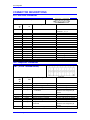
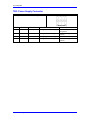
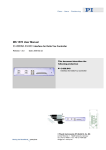
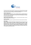
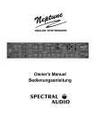
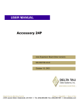
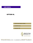
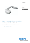
^1 USER MANUAL
^2 Accessory 8M
^3 Mini-PMAC Extender Board
^4 3Ax-603410-xUxx
^5 October 29, 2003
Single Source Machine Control
Power // Flexibility // Ease of Use
21314 Lassen Street Chatsworth, CA 91311 // Tel. (818) 998-2095 Fax. (818) 998-7807 // www.deltatau.com
\
Copyright Information
© 2003 Delta Tau Data Systems, Inc. All rights reserved.
This document is furnished for the customers of Delta Tau Data Systems, Inc. Other uses are
unauthorized without written permission of Delta Tau Data Systems, Inc. Information contained
in this manual may be updated from time-to-time due to product improvements, etc., and may not
conform in every respect to former issues.
To report errors or inconsistencies, call or email:
Delta Tau Data Systems, Inc. Technical Support
Phone: (818) 717-5656
Fax: (818) 998-7807
Email: [email protected]
Website: http://www.deltatau.com
Operating Conditions
All Delta Tau Data Systems, Inc. motion controller products, accessories, and amplifiers contain
static sensitive components that can be damaged by incorrect handling. When installing or
handling Delta Tau Data Systems, Inc. products, avoid contact with highly insulated materials.
Only qualified personnel should be allowed to handle this equipment.
In the case of industrial applications, we expect our products to be protected from hazardous or
conductive materials and/or environments that could cause harm to the controller by damaging
components or causing electrical shorts. When our products are used in an industrial
environment, install them into an industrial electrical cabinet or industrial PC to protect them
from excessive or corrosive moisture, abnormal ambient temperatures, and conductive materials.
If Delta Tau Data Systems, Inc. products are directly exposed to hazardous or conductive
materials and/or environments, we cannot guarantee their operation.
Accessory 8M
Table of Contents
INTRODUCTION ........................................................................................................................................ 1
Setting up the Board................................................................................................................................... 1
CONNECTING THE BOARD.................................................................................................................... 3
Power-Supply Connection.......................................................................................................................... 3
Mini-PMAC Connection ............................................................................................................................ 3
Amplifier Connection................................................................................................................................. 3
SETTING UP THE MINI-PMAC............................................................................................................... 5
Analog Outputs .......................................................................................................................................... 5
Enable and Fault Flags ............................................................................................................................... 5
JUMPER DESCRIPTIONS......................................................................................................................... 7
E1A ............................................................................................................................................................ 7
E1B ............................................................................................................................................................ 7
E2A ............................................................................................................................................................ 7
E2B ............................................................................................................................................................ 7
CONNECTOR DESCRIPTIONS ............................................................................................................... 9
JS1: A/D Port Connector............................................................................................................................ 9
JS1 (16-Pin Header) .............................................................................................................................. 9
TB1: Amplifier Connector ......................................................................................................................... 9
TB1 (10-Pin Terminal Block) ................................................................................................................ 9
TB2: Power-Supply Connector ................................................................................................................ 11
TB2 (4-Pin Terminal Block) ................................................................................................................ 11
Table of Contents
i
Accessory 8M
ii
Table of Contents
Accessory 8M
INTRODUCTION
The Accessory 8M Mini-PMAC Extender Board, part number 603410-10x, is designed to extend
the capability of the 2-channel Mini-PMAC board to interface to an extra pair of analog velocitymode or torque-mode amplifiers, or a single additional “sine-wave” amplifier. The extender
board picks up the digital signals for the extra 2 analog outputs that are generated, but not
utilized, on the Mini-PMAC, converts them to analog format, and outputs them to the drive. It
also buffers and isolates the amplifier-enable outputs and the amplifier-fault inputs for these two
channels.
The two interface channels on the extender board are labeled Channels 3 and 4. The amplifier
interface lines for Channels 1 and 2 are on the Mini-PMAC board itself. Encoder inputs for
Channels 3 and 4 are provided standard on the Mini-PMAC. If home and limit flag inputs are
desired for Channels 3 and 4, Option 14M can be purchased for the Mini-PMAC, which provides
these inputs on the Mini-PMAC itself.
Setting up the Board
Very little preliminary setup is required for the extender board before it is connected to the
system.
Jumpers E1A and E1B control the format of the amplifier-enable output for Channel 3.
•
•
•
Connect pins 1 and 2 of E1A and pins 1 and 2 of E1B for a sinking output on AENA3.
Connect pins 2 and 3 of E1A and pins 2 and 3 of E1B for a sourcing output on AENA3.
Connect pins 1 and 2 of E1A and pins 2 and 3 of E1B for a sinking/sourcing (totem-pole)
output on AENA3.
Fuse F1 limits the current of AENA3 to 0.5A in either direction.
Jumpers E2A and E2B control the format of the amplifier-enable output for Channel 4.
•
•
•
Connect pins 1 and 2 of E2A and pins 1 and 2 of E2B for a sinking output on AENA4.
Connect pins 2 and 3 of E2A and pins 2 and 3 of E2B for a sourcing output on AENA4.
Connect pins 1 and 2 of E2A and pins 2 and 3 of E2B for a sinking/sourcing (totem-pole)
output on AENA4.
Fuse F2 limits the current of AENA4 to 0.5A in either direct.
Introduction
1
Accessory 8M
2
Introduction
Accessory 8M
CONNECTING THE BOARD
Power-Supply Connection
The extender board requires an external unregulated +/-12V to +/-15V supply for its analog
circuits. This supply must be brought in on TB2. The supply used can be the same as that used
for the analog circuits on the Mini-PMAC itself. If it is desired to maintain the provided optical
isolation between this analog circuitry and the digital 5V circuitry on the Mini-PMAC itself, this
must be a separate supply from the 5V supply for the Mini-PMAC, and the analog common
(AGND) must not be tied to the digital common (GND), except possibly at the signal system
“star” grounding point.
The digital 5V circuitry on the extender board is supplied automatically through the cable from
the Mini-PMAC board.
Note
The green “power-good” LED on the board (component D9) will be lit
only if all of the following signals are present:
•
•
•
•
The A+12V/+15V positive analog supply
The A-12V/-15V negative analog supply
The A+5V internal analog supply from the on-board regulator
The DAC clock signal from the Mini-PMAC
If any of these signals is not present, the D9 LED will go off, and the on-board relay supplying
power to the output op-amps will open, disabling the analog outputs.
Mini-PMAC Connection
The extender board is connected to the Mini-PMAC through the provided 16-strand flat cable.
This cable connects header JS1 on the extender board to header J7 on the Mini-PMAC.
The J7 header on the Mini-PMAC can also be used to connect the Mini-PMAC to the ACC-28A
or ACC-28B A/D-converter board. To connect the Mini-PMAC to both an ACC-28 board and an
extender board, daisy-chained them on a 3-drop cable. There is no signal or address conflict
between these two accessory boards.
Amplifier Connection
The analog command outputs, the amplifier-enable/direction outputs, the amplifier fault inputs,
and the AGND reference voltage of the extender board are connected to the amplifier(s) through
terminal block TB1.
The analog command outputs can be connected as single-ended outputs, in which the command
voltage is the voltage of DAC+ with respect to AGND. In this case, the DAC- pin should be left
floating – do not ground this output if you are not using it! Alternately, the analog outputs can be
used in differential mode, in which the command voltage is the voltage of DAC+ with respect to
DAC-. In this case, it is still important to tie the AGND reference voltage of the extender board
to the analog reference voltage of the amplifier.
If Option 14M, which provides all of the flag inputs for Channels 3 and 4, is present on the MiniPMAC, the amplifier-fault inputs FAULT3 and FAULT4 can be brought in either on the extender
board, or the Mini-PMAC itself. If the rest of the amplifier signal connections for these channels
are brought in on the extender board, it is probably advisable to bring the fault signals in on the
extender board also. Whichever input is not used should be left floating to avoid signal conflict.
Connecting the Board
3
Accessory 8M
4
Connecting the Board
Accessory 8M
SETTING UP THE MINI-PMAC
Analog Outputs
The two D/A converters on the extender board appear as DAC3 and DAC4 to the Mini-PMAC
software, just as if they were on-board D/A converters. The value written into the high 16 bits of
Y:$C00B creates a proportional voltage on the DAC3 and DAC3/ outputs; the value written into
the high 16 bits of Y:$C00A creates a proportional voltage on the DAC4 and DAC4/ outputs.
To use the extender board for servo outputs when Mini-PMAC is not commutating the motor,
Ix02 for the motor must contain the address of the individual DAC register used in its low 16 bits:
$C00B for DAC3, and $C00A for DAC4. These are the default values for I302 and I402,
respectively. Normally, bit 16 of Ix02 is set to 0; it should be set to 1 if the DAC register is to
receive the unsigned magnitude of the servo command value (the AENA line outputs the sign of
the command in this mode).
To use the extender board for a pair of analog outputs (“sine-wave outputs”), when Mini-PMAC
is commutating the motor, Ix02 for the motor must contain the lower address of the DAC pair
used in its low 16 bits: $C00A for DAC3 and DAC4. Normally, bit 16 of Ix02 is set to 0; it
should be set to 1 when the sine-wave output pair is used for open-loop “direct microstepping”
commutation.
Enable and Fault Flags
To use the AENA outputs on the extender board as the automatic amplifier-enable control lines or
the FAULT inputs as the automatic amplifier-fault status lines, Ix25 must contain the address of
the flag register used in its low 16 bits: $C008 for Channel 3; $C00C for Channel 4. These are
the default values for I325 and I425, respectively. The high 8 bits of Ix25 control whether the
individual lines are used, and how they are used.
It is also possible to use the amplifier-enable outputs as general-purpose digital outputs. To do
this, make sure they are not used for the automatic amplifier-enable function. Typically this is
done by setting bit 16 of Ix25 to 1 (e.g. I325=$1C008). Then an M-variable can be assigned to
the amplifier-enable control bit. M314 is the suggested M-variable for AENA3; M414 is the
suggested M-variable for AENA4 (see the suggested M-variable definitions in the PMAC
Software Reference Manual).
The amplifier-fault inputs can be used as general-purpose digital inputs. To do this make sure
they are not used for the automatic amplifier-fault function. Typically, this is done by setting bit
20 of Ix25 to 1 (e.g. I325=$10C00B). Then an M-variable can be assigned to the amplifier-fault
status bit. M323 is the suggested M-variable for FAULT3; M423 is the suggested M-variable for
FAULT4 (see the suggested M-variable definitions in the PMAC Software Reference Manual).
Setting Up the Mini-PMAC
5
Accessory 8M
6
Setting Up the Mini-PMAC
Accessory 8M
JUMPER DESCRIPTIONS
E1A
•
•
Jump pins 1 and 2 to tie driver IC output for AENA3 to cathode of blocking diode. If E1B
also connects pins 1 and 2, diode blocks sourcing of current by the driver IC output,
permitting sinking of current only. If E1B connects pins 2 and 3, diode does not block
current in either direction, permitting sinking and sourcing of current by driver IC.
Jump pins 2 and 3 to tie driver IC output for AENA3 to anode of blocking diode. If E1B also
connects pins 2 and 3, diode blocks sinking of current by the driver IC output, permitting
sourcing of current only. If E1B connects pins 1 and 2, diode does not block current in either
direction, permitting sinking and sourcing of current by driver IC.
E1B
•
•
Jump pins 1 and 2 to tie anode of blocking diode to output terminal block pin for AENA3. If
E1A also connects pins 1 and 2, diode blocks sourcing of current by the driver IC output,
permitting sinking of current only. If E1A connects pins 2 and 3, diode does not block
current in either direction, permitting sinking and sourcing of current by driver IC.
Jump pins 2 and 3 to tie cathode of blocking diode to output terminal block pin for AENA3.
If E1A also connects pins 2 and 3, diode blocks sinking of current by driver IC output,
permitting sourcing of current only. If E1A connects pins 1 and 2, diode does not block
current in either direction, permitting sinking and sourcing of current by driver IC.
E2A
•
•
Jump pins 1 and 2 to tie driver IC output for AENA4 to cathode of blocking diode. If E2B
also connects pins 1 and 2, diode blocks sourcing of current by the driver IC output,
permitting sinking of current only. If E2B connects pins 2 and 3, diode does not block
current in either direction, permitting sinking and sourcing of current by driver IC.
Jump pins 2 and 3 to tie driver IC output for AENA4 to anode of blocking diode. If E2B also
connects pins 2 and 3, diode blocks sinking of current by the driver IC output, permitting
sourcing of current only. If E2B connects pins 1 and 2, diode does not block current in either
direction, permitting sinking and sourcing of current by driver IC.
E2B
•
•
Jump pins 1 and 2 to tie anode of blocking diode to output terminal block pin for AENA4. If
E2A also connects pins 1 and 2, diode blocks sourcing of current by the driver IC output,
permitting sinking of current only. If E2A connects pins 2 and 3, diode does not block
current in either direction, permitting sinking and sourcing of current by driver IC.
Jump pins 2 and 3 to tie cathode of blocking diode to output terminal block pin for AENA4.
If E2A also connects pins 2 and 3, diode blocks sinking of current by driver IC output,
permitting sourcing of current only. If E2A connects pins 1 and 2, diode does not block
current in either direction, permitting sinking and sourcing of current by driver IC
Jumper Descriptions
7
Accessory 8M
8
Jumper Descriptions
Accessory 8M
CONNECTOR DESCRIPTIONS
JS1: A/D Port Connector
JS1 (16-Pin Header)
Front View
Sy
mb
ol
DCLK
BDATA1
ASEL0/
ASEL1/
CNVRT01
ADCIN1
OUT1/
OUT2/
OUT3/
OUT4/
HF41
HF42
HF43
HF44
+5V
GND
Functi
on
Input
Input
N.C.
Input
N.C.
N.C.
N.C.
N.C.
Input
Input
N.C.
N.C.
Output
Output
Input
Common
Description
D to A, A to D Clock
Notes
D to A Data
DAC and ADC clock for
Channels 1, 2, 3, 4
DAC data for Channels 1, 2, 3, 4
Chan Select Bit 1
Select for Channels 3, 4
Amp Enable/Dir
Amp Enable/Dir
Amp enable/dir for Channel 3
AMP enable/DIR. for Channel 4
Amp Fault
Amp Fault
+5V Supply
Digital Reference
Amp fault signal for Channel 3
Amp fault signal for Channel 4
Power supply
TB1: Amplifier Connector
TB1 (10-Pin Terminal Block)
Front View
Sy
mb
ol
Funct
ion
Description
AGND
DAC3+
DAC3AENA3
Common
Output
Output
Output
Analog Reference Voltage
Positive Analog Command
Negative Analog Command
Amplifier Enable / Direction
Command
FAULT3
AGND
DAC4+
DAC4AENA4
Input
Common
Output
Output
Output
Amplifier Fault Signal; Channel 3
Analog Reference Voltage
Positive Analog Command
Negative Analog Command
Amplifier Enable / Direction
Command
FAULT4
Input
Amplifier Fault Signal; Channel 3
Connector Descriptions
Notes
+/-10V with respect to AGND
+/-10V with respect to AGND
Software selected function;
Hardware selected polarity &
format
Software selected polarity
+/-10V with respect to AGND
+/-10V with respect to AGND
Software selected function;
Hardware selected polarity &
format
Software selected polarity
9
Accessory 8M
10
Connector Descriptions
Accessory 8M
TB2: Power-Supply Connector
TB2 (4-Pin Terminal Block)
Front View
Pin #
Symbol
Function
Description
Notes
1
A+15V
Input
Analog Positive Input Supply
2
AGND
Common
Analog Reference Voltage
3
4
A-15V
AGND
Input
Common
Analog Negative Input Supply
Analog Reference Voltage
+12V TO +15V,
Unregulated
Isolated from digital
common
-12V TO -15V, Unregulated
Isolated from digital
common
Connector Descriptions
11