1
IIIIIIIIIIIIIIIIIII
USOO508328 A
United States Patent [19]
[11]
Patent Number:
Hino et al.
[45]
Date of Patent:
[54] IMAGE FORMING APPARATUS
4,826,332
RECEIVING EXTERNAL DATA TO
PERFORM A PREDETERMINED PROCESS
5,083,286
Jan. 21, 1992
5/1989
Ukai et al. ........................... .. 400/70
4,979,144 12/1990
4,980,856 12/1990
4,985,920 1/1991
Seki ............................... .. 235/380 X
[75] Inventors: Rika Hino, Tokyo; Kimio Osawa,
Yokohama, both of Japan
[73] Assignee: Kabushiki Kaisha Toshiba, Kawasaki,
FOREIGN PATENT DOCUMENTS
3247791
Japan
7/1983 Fed. Rep. of Germany .
OTHER PUBLICATIONS
[2]] Appl. No.: 413,303
Hewlett Packard User Manual, Aug. 1986, pp. 4-7»
[22] Filed:
Sep. 27, 1989
[30]
Foreign Application Priority Data
4-10.
Sep. 30, 1988 [JP]
Primary Exam1'ner—Heather R. Herndon
Attorney, Agent, or Firm—Fo1ey & Lardner
Japan .............................. .. 63-245999
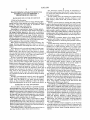
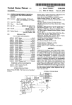
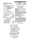
[57]
G06K 19/00
ABSTRACT
[51]
Int. Cl.5 .......................... ..
[52]
U5. Cl. .................................................. .. 395/115
[58]
Field of Search ..................... .. 364/518, 521, 519;
down-loaded from a host device to a RAM and then
365/52; 355/206, 271, 133, 202, 209; 434/156,
written in an IC card. Once the initialization data is
Initialization data for an image forming apparatus is ?rst
157
written in the IC card, future initialization will be exe
.
[56]
cuted on the basis of the initialization data read out from
References Cited
U.S. PATENT DOCUMENTS
the IC card, not from the host device.
3,988,721 10/1976 Frutiger ........................ 1. 340/173 R
48
53
8 Claims, 8 Drawing Sheets
___,\ HOST
<:_i:> 17>;
——/ INTERFACE $9 $3
\
\
EXTENSION
MEMORY
<:
I60
CIRCUIT
-—/ CIRCuIT
<:
ROM <——
5
54
m
I
I-I-I
5
VIDEO
RAM
E
a
1
CIRCUIT
;> RAM L52
~61
<;—
—>
CPU
II
SERIAL-
47,49
<9 Ic CARD
64
67
13> CONNECTION <3 16 CARD
51
I
t
V
PARALLEL
OPERATI ON
CONVERSION PANEL
CIRCUIT
CONTROL
\
CIRCUIT
55
,65
:> CONNECTION <:> Ic CARD
‘
5
59b
62
A63 CONNECTION 66
PRINTER
(12> INTERFACE
‘
0
OPERATION
PANEL
~56
~
50
US. Patent
Jan. 21, 1992
Sheet 1 of 8
5,083,286
US. Patent
Jan. 21, 1992
Sheet 2 of 8
5,083,286
U.S. Patent
Jan. 21, 1992
Sheet 3 of 8
5,083,286
ON - L I NE
READY
DATA
\9
OPERATOR
SERVICE
MODE
~~9b
r
W
~~9Cl
\
J
"\._,9C
I
I
li
K\)(]
65 -c::| -> :::3
66'\*::::;:: —-> :3
___
67: -> ___:
{Ob
48
{0C
-
H
xi’!
48F’
FIG. 4
;
'
US. Patent
Jan. 21, 1992
(
START
Sheet 6 of 8
5,083,286
)
DISPLAY DOWNx5,
LOADING PERMISSION
T
INITIATE
DOWN-LOADTNG
~52
83
TO BE
STORED INTO IC
CARD '?
YES
s4
as IC
CARD |N§ERTED
YES
A
58
S1‘
TURN IC CARD
INSTRUCT IC
POWER ON
.
CARD INSERTION
mm 10OFF
CARD
POWER
STORE INTO IC CARD
|
3 s TDR IN
89
FIN'SHED?
YES
‘S5
\NSTRUCT IC CARD
-
SUBSTITUTION
5:0
mm 10 CARD
POWER OFF
E N D
FIG. 7
US. Patent
Jan. 21, 1992
Sheet 7 of 8
5,083,286
FROM Si
1
INITIATE
~52
DOWN - LOADING
IS
WRITING lNTO
IC CA'PRD OK
‘
TURN 1C CARD
POWER ON
_|NSTRUCT
IC CARD
INSERTION
(S18
STORE DATA
TO IC CARD
l
TO 83
FIG,
5J9
8
U.S. Patent
Jan. 21, 1992
Sheet 8 of8
,
5,083,286
FROM 51
LOADING FROM
IC CARD?
YES 52!
TURN IC CARD
POWER ON
\
£522
‘
READ IC CARD
ID NUMBER
S24
\
TURN IC CARD
POWER OFF
(825
DISPLAY ID NO.
INVALIDITY
> YES 8x2
INITIATE
DOWN-LOADING
&
F | s.
TO S3
FROM S6 OR ST
%
FETCH
A»
STORE TIME
~
TIME DATA
DATA — RAM
STORE DATA
To 1c CARD
TO 89
FIG.
{O
s26
527
“'52s
9
1
5,083,286
IMAGE FORMING APPARATUS RECEIVING
EXTERNAL DATA TO PERFORM A
PREDETERMINED PROCESS
2
?rst instruction means for giving an instruction to
write the predetermined data stored in said load mem
ory means into said portable memory medium from said
load memory means;
second loading means for loading the predetermined
BACKGROUND OF THE INVENTION
1. Field of the Invention
The present invention relates to image forming appa
ratuses such as a laser printer and an electronic copying
machine, which form an image in accordance with
image data sent from a host device.
2. Description of the Related Art
According to conventional image forming appara
tuses, in altering an operation mode which is not built in
the image forming apparatus, data such as emulation
data and font data (hereinafter referred to as down-load
data) is down-loaded to an image forming apparatus
from a computer as a host device, an image scanner or
data stored in said portable memory medium to said
load memory means from said portable memory me
dium; and
memory control means for writing into said portable
memory medium said predetermined data loaded to said
load memory means from said host device by said ?rst
loading means when instructed by said ?rst instruction
means, and loading said predetermined data stored in
said portable memory medium to said load memory
means when said portable memory medium having said
predetermined data loaded thereto‘ is set in said appara
tus, thereby executing initialization of said image form
ing apparatus.
the like, and data necessary for the apparatus to perform 20 According to another aspect of an image forming
apparatus according to claim 1, further comprising:
a predetermined operation is set to the individual units
receiving means for receiving said portable memory
of the apparatus, thus executing initialization.
When the down-load data is set where necessary, the
medium;
second instruction means for giving a power supply
image forming apparatus becomes ready to form an
image in accordance with image data sent from the host 25 instruction to supply power to said portable memory
medium set in said receiving means or a power stop
device.
instruction to stop power supply to said portable mem
According to such conventional image forming appa
ory medium; and supply or stoppage of power supply to
ratuses, however, down-load data should be down
said portable memory medium in accordance with the
loaded from a host device every time power is turned
instructions
from said second instruction means,
on or an operation mode is changed. The down-loading
whereby at a time said portable memory medium is
occupies the host device every time and signi?cantly
set in or removed from said receiving means, power to
impairs the effective use of the host device.
said portable memory medium is cut off in response to
As one of a possible image forming apparatuses (not a
the power stop instruction from said second instruction
power art), there may be an apparatus which employs
means, and when said portable memory medium is set in
an IC card (portable memory medium) having a pro
said receiving means, power is given to said portable
gram, fonts and other various data stored in an inte
memory medium in response to the power supply in
grated circuit chip mounted therein and loads these data
struction from said second instruction means.
as desired into a RAM provided in the image forming
Both of the above image forming apparatuses has a
apparatus to execute an operation. When the IC card is
further feature such that portable memory media for use
inserted in or removed from the apparatus which has
in the apparatuses are colored differently depending on
already been activated to be ready for operation, noise
types thereof and types of data stored therein.
may occur at the connector section of the apparatus
According to the present invention, in an image form
which receives the IC card, thus destroying the mem
ing apparatus which down-loads predetermined data
ory contents in both the IC card and the image forming
apparatus.
Further, conventional IC cards for use in the possible
image forming apparatuses, even they are of different
types, have the similar or the same external appear
ances, so that it becomes difficult to select the proper
type, thus making the use of the IC cards inconvenient.
45 from a host device for initialization, data down-loaded
from the host device ?rst is stored in a portable memory
medium, so that when this data should be down-loaded
next time, it is loaded from the portable memory me
dium. This reduces a burden of the host device and
improves the effective use thereof.
According to a modi?cation of the present invention,
control means for controlling power supply to the por
table memory medium and cutoff of the power supply
in accordance with an instruction from second instruc
forming apparatus which make down-loading of down
load data from a host device unnecessary every time the 55 tion means, whereby inserting or removing of the porta
ble memory medium is carried out while power supply
apparatus is activated or the operation mode is changed,
to the portable memory medium is cut off by the control
permits a portable memory medium to be inserted into
means, and power is given to the memory medium
or removed from the activated apparatus, uses portable
when the memory medium is surely inserted in the
memory media whose types can be apparently distin
apparatus. This can prevent the otherwise possible data
guished, and is therefore easy to operate.
SUMMARY OF THE INVENTION
It is an object of this invention to provide an image
To achieve the object, there is provided an image
destruction, and makes the image forming apparatus
forming apparatus which is initialized by down-loading
easy to operate as it is unnecessary to cut off power to
the overall apparatus.
predetermined data from a host device to load memory
Further, portable memory media for use in the image
means for storing the predetermined data and loads data
from a portable memory medium into said load memory 65 forming apparatus are colored differently depending on
the types of data stored therein to avoid confusion, thus
means, said apparatus comprising:
making the present image forming apparatus easier to
?rst loading means to load said predetermined data to
operate.
said load memory means from said host device;
3
5,083,286
BRIEF DESCRIPTION OF THE DRAWINGS
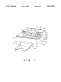
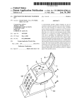
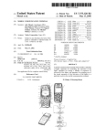
FIG. 1 is a perspective view illustrating the external
appearance of an image forming apparatus according to
one embodiment of the present invention;
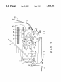
FIG. 2 is a schematic longitudinal cross section of the
apparatus shown in FIG. 1;
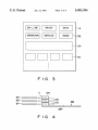
FIG. 3 is a diagram illustrating an arrangement of an
4
de-electrifying unit 22 (the last two units serving as
cleaner means).
In the printer body 5 an image-support member con
veying path 24 is formed passing through an image
transfer section 23 between the photosensitive drum 15
and the transfer unit 19 and extending forward. A sheet
of paper P automatically fed via a feed roller 28 and
guide rollers 29 from a sheet feeding cassette 25 accom
modated at the bottom portion in the printer body 5 or
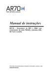
FIG. 4 is a diagram illustrating connection between 0 a sheet of paper P manually fed from the manual feed
operation panel of FIG. 1;
an IC card and a circuit board having a control circuit
tray 13 is guided along this path 24 to ‘the image transfer
section 23.
A pair of aligning rollers 30 are disposed along the
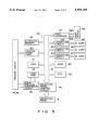
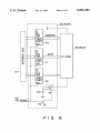
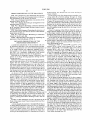
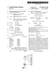
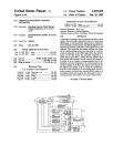
FIG. 5 is a block diagram illustrating the structure of
image-support member conveying path at the upstream
the essential section of an electric circuit of the embodi
15 of the image transfer section 23, and a ?xing unit 31, a
ment shown in FIG. 1;
discharge sheet selector 32 and a pair of discharge rol
FIG. 6 is a block diagram illustrating a connection
lers 33 ar disposed at the downstream of the section 23.
circuit for the IC card; and
At the end of the path 24 is formed a branching path
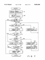
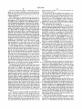
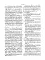
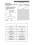
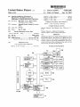
FIGS. 7 through 10 are flowcharts for explaining the
mounted thereon;
operation of the embodiment of FIG. 1.
DETAILED DESCRIPTION OF THE
PREFERRED EMBODIMENT
A preferred embodiment of this invention will now
be described referring to the accompanying drawings.
35 provided with a pair of discharge rollers 34 along
which paper P selected by the discharge sheet selector
32 is guided toward the recess portion 6 serving as a
sheet discharging section.
Referring to FIG. 1, numeral 40 is a lower cover,
numeral 41 is a front cover, numeral 42 is an upper
FIG. 1 is a perspective view of the external appearance 25 cover, numeral 43 is an openable right cover (door),
of an image forming unit apparatus equipped with a
laser printer as the present image forming apparatus,
and FIG. 2 is a schematic longitudinal cross section
illustrating the internal structure of the apparatus.
Referring to the diagrams, numeral 1 denotes a laser
printer as an image forming apparatus having the fol
lowing structure.
Reference numeral 5 is the body of the laser printer 1,
and the top rear portion of the printer body 5 is made
higher than the front portion. A recessed portion 6
serving as a sheet discharging section is provided at the
top center portion of the printer body 5. A sheet dis
charging tray 8 is mounted in the recessed portion 6 and
is supported movable by a jogger 7. On the right side of
the recessed portion 6 is an operation panel 9, and on the
left side there are three IC-card slots 11.
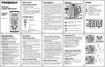
As shown in FIG. 3, the operation panel (?rst and
second instruction means) 9 comprises an LCD (Liquid
Crystal Display) unit 90 for displaying the number of
sheets, a mode, etc., an LED (Light Emitting Diode) 45
indicator 912 for indicating various statuses by turning
LEDs on, and switches 90 for specifying various opera
tions. The LED indicator 917 comprises LEDs which
indicate whether or not the apparatus is coupled to an
external unit (i.e., an ON/OFF-line mode), a print ready
mode, a manual mode, print data transfer in progress, an
operator’s attention required (operator call) and atten
dance of a service man required (service man call).
numeral 44 is a left cover, numeral 45 is a lever for
opening or closing the right cover 43, and numeral 46 is
a lever for opening or closing the upper unit. Referring
to FIG. 2, numeral 47 denote a circuit board on which
a printer circuit for controlling the operation of the
printer itself is mounted, and numeral 48P denote a
circuit board on which a printer control circuit 48 for
controlling the operation of the printer circuits 49 is
mounted. As shown in FIG. 4, the circuit board 48P
having the printer control circuit 48 mounted thereon
has three connectors (receiving means) 10a, 10b and 10c
mounted directly at one end thereof, thus forming the
IC-card slots 11 in which IC cards (portable memory
media) 65, 66 and 67 are to be respectively inserted.
This structure can eliminate the need to lay signal lines
around by means of harnesses, thus shortening the
lengths of the signal lines. This reduces a delay in the
signal lines as well as a cross talk, thus ensuring a high
speed access to the IC cards 65-67.
In the image forming operation of the above appara
tus, the photosensitive drum 15 is uniformly charged by
the charging unit 16 and is then exposed to light by
means of the laser optical system 17 in accordance with
an image signal, thus forming an electrostatic latent
image on the drum 15. This electrostatic latent image on
the photosensitive drum 15 is developed by the devel
oping unit 18 which uses a two-component developer D
consisting of a toner and a carrier b, and the resultant
developed image is sent to the image transfer section 23.
The switches 9c include numeral (ten) keys, an ON/
In synchronism with the above developing operation,
OFF select key, a clear key, a YES key, a NO key, and 55
the paper P fed out from the sheet cassette 25 or the
an EXIT key, for example. The ten keys are used to set
manually-fed paper P is fed via the aligning roller pair
a number-of-copies setting mode, a paper source feed
mode, a printing abort/sheet discharge mode, and the
like.
Further, a sheet discharge tray 12 is mounted at the
front of the printer body 5, and a manual feed tray 13 at
the rear side.
A drum-shaped photosensitive member 15 serving as
an image bearing member is shown in FIG. 2. Disposed
30 to the image transfer section 23 where the developed
image is transferred on the paper P by the transfer unit
19. The paper P is then separated from the photosensi
tive drum 15 by the separating unit 20, and is fed to the
?xing unit 31 along the image-support member convey
ing path 24. After the developed image transferred on
the paper P is ?xed thereon by the ?xing unit 31, the
discharging direction is selected by the discharge sheet
around the photosensitive drum 5 are a charging unit 65
selector 32 so that the paper P with the ?xed image is
16, a laser optical system 17, a developing unit 18, a
discharged to the upper sheet discharge tray 8 or the
transfer unit 19, a separating unit 20 (the last three units
front sheet discharge tray 12.
serving as developing means), a cleaning unit 21 and a
5
5,083,286
After the developed image is transferred onto the
paper P, the toner remaining on the photosensitive
drum 15 is cleaned off by the cleaning device 21 and the
image forming apparatus becomes ready for the next
copying operation.
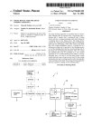
FIG. 5 illustrates the essential section of the electric
circuit of the printer control section 48. Referring to
this diagram, a CPU 50 performs the general control of
the image forming apparatus, and a ROM 51 stores a
control program according to which the CPU 50 oper
ates. Stored in the ROM 51 are a password (ID number)
which should be referred to upon data alteration and
other data associated with the paper P such as the top
6
which otherwise is likely to occur upon insertion or
removal of the cards.
The connection circuits 62-64 each comprise a tri
state buffer circuit 70 for disabling an address signal line
to stop address data from the internal bus 61, a tri-state
buffer circuit 71 for disabling a data signal line, a tri
state buffer circuit 72 for disabling a control signal line,
a power source Vcc for supplying power to the 1C
cards 65-67, a relay circuit 73 for permitting or inhibit
ing the output of the power source Vcc, and a transistor
74 for driving the relay circuit 73.
At the time the IC cards 65-67 are inserted to or
removed from the present apparatus, a PS ON signal
from the CPU 50 is disabled ?rst to inhibit the output of
margin, left margin and paper type. A RAM 52 is used
the transistor 74. This opens the contact of the relay
as a page buffer for temporary storage of image data
circuit
73 to thereby cut off the power supply to the 1C
sent from a host device 58 or a working buffer for the
cards 65-67. A signal to be supplied to an enable (EN)
CPU 50. An extension memory 53 is a large-capacity
terminal of each of the tri-state buffer circuits 70-72 is
memory which is used when image data from the host
also disabled, rendering the output terminal of each
device 58 is bit-map data or the like so that the RAM 52
20 tristate buffer circuit at a high impedance state. As a
cannot store data for one page. A video RAM 54 stores
result, the connection circuits 62-64 are electrically
image data developed into a bit image, and its output is
separated from the IC cards 65-67, respectively. The IC
supplied to a serial-parallel conversion circuit 55. The
cards 65-67 in this state are inserted into or removed
serial-parallel conversion circuit 55 converts image
from the connectors 100-100. At the time power is
data, developed into a bit image in the video RAM 54
supplied to the IC cards 65-67, with the cards electri
and transferred as parallel data therefrom, into serial
cally separated from the connection circuits 62-64 in
data and outputs this data to the printer circuits 47, 49.
the above manner, the cards are inserted into the con
A host interface 57 serves to exchange data between
nectors 10a-10c and the PS ON signal from the CPU 50
the host device 58, which may be constituted by a com
is enabled to turn on the transistor 74. As a conse
puter or an image scanner, and the printer control sec
tion 48. The host interface 57 has two types of transfer
lines, a serial transfer line 59a and a parallel transfer line
59b, and can selectively use these lines in accordance
with the type of data transferred to or from the host
device 58. A printer interface 60 serves to permit the use
of a control signal line between the printer control sec
tion 48 and the printer circuits 47, 49. Connection cir
cuits 62 to 64 control power supply to and power cutoff
quence, the contact of the relay circuit 73 is closed, so
that power supply to the IC cards 65-67 starts. Further,
since the signal to be supplied to the EN terminal of
each tristate buffer circuit 70, 71 or 72 is also enabled,
data supplied to its input terminal appears as it is on the
output terminal. Accordingly, the connection circuits
62-64 are electrically coupled to the respective IC cards
65-67 thus permitting data to be read from or written in
the cards.
from the IC cards 65-67 at the time the IC cards are
A description will now be given of the operation of
inserted into or removed from the present apparatus.
This control will be described in detail later.
the present image forming apparatus with the above
An operation panel control circuit (?rst and second
control means) 56 permits the LCD unit 90 of the opera
tion panel 9 to display and transfer data, entered
structure for down-loading data and writing the down
loaded data (predetermined data) in the IC card 65
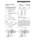
referring to the flowchart shown in FIG. 7. The CPU
50 permits the LCD unit 90 of the operation panel 9 to
through the switches 9c, to the CPU 50. An internal bus
61 serves to exchange data between the CPU 50, ROM
51, RAM 52, extension memory 53, video RAM 54,
display that down-loading is permitted (step S1). When
operation panel control circuit 56, host interface 57,
(step S2). More speci?cally, data transferred over the
printer interface 60 and connection circuits 62-64. The
data transfer line 5911 or 59b to the host interface 57
IC cards 65-67 are each constituted by a nonvolatile
memory, such as a battery-backed-up static RAM, EE~
PROM, EPROM or mask ROM. These IC cards 65-67
from the host device 58 is sequentially stored in the
RAM 52 via the internal bus 61.
are colored distinctively depending on the types of the
above memories and the functions associated with the
pleted, writing the down-loarded data into the IC card
is instructed in step S3 from the operation panel 9, and
the operator sets the apparatus in ON~line state in re
sponse to the message, down-loading of data is initiated
After down-loading the data to the RAM 52 is com
memory contents. For instance, an IC card of a mask 55 it is discriminated whether or not the IC card 65 is
ROM type having font data recorded therein may be
colored blue, and an host device of a static RAM type
having emulation data recorded therein may be colored
orange. This permits a user to con?rm at a glance the
type'of a IC card in use and the type of data written in
the card.
The connection circuits (control means) 62-64 each
have a structure as shown in FIG. 6, and function in
such a way that when the 1C cards 65-67 are inserted
into or removed from the connecters l0a—10c, power
supply to these cards is cut off, and the signal lines to
the cards are disabled, thus preventing data stored in the
IC cards 65-67 from being destroyed due to noise
actually inserted into the connector 10a (step S4). If the
decision is negative, the CPU 50 displays the insertion
of the IC card on the control panel 9a at stop 11 and
waits for data denoting that the operator has inserted
the IC card 65 (steps S4 and S11). When the data is
entered, the CPU 50 enables the PS ON signal again
(step S5) and goes to step S6. The loop of steps S4 to
S11 is repeated until insertion of the IC card 65 is actu
ally detected in the above manner.
When it is discriminated in step S4 that the IC card 65
has actually been set in the proper position, it is then
checked if no data has been written in the card yet (step
S6). If it is discriminated that data has already been
7
5,083,286
8
As described above, the present invention can pro
written in the IC card, a message to that effect is output
to ask if re-writing of the IC card can be performed or
not to the operator (step S7). When the answer is no, the
flow then returns to step S4 via steps S12 and S13 and
vide an image forming apparatus with higher operabil
ity, which does not require down-loading of down-load
the aforementioned operational sequence is repeated.
operation mode is changed, can permit a portable mem
When the IC card 65 is actually inserted and it is
discriminated that no data has been written in the card
ory medium to be inserted in or removed from the pres
yet or the re-writing can be performed, the flow ad
can permit an operator to distinguish, at a glance, the
type of a portable memory medium in use.
What is claimed is:
vances to step S8 where the down-load data stored in
the RAM 52 is sequentially written in the IC card 56. In
this manner, in loading emulation data, font data, etc. to
data from a host device every time power is given or the
ent apparatus even when the apparatus is activated, and
1. An image forming apparatus initialized by down
loading predetermined initialization data from a host
the RAM 52 next, the data can be loaded from this IC
card 65, not from the host device 58.
device to a load memory means for storing the predeter
Since down-load data temporarily loaded into the
RAM 52 is written in each of the IC cards 65-67 in
mined data, comprising:
?rst loading means for loading said predetermined
response to an instruction entered from the operation
panel 9, as described above, the same data can be loaded
to the RAM 52 next time from the associated IC card,
not from the host device 58. Accordingly, the host
device 58 need not perform down-loading of data every 20
time power to the image forming apparatus is cut off or
an operation mode is changed, thus increasing the effec
initialization data to said load memory means from
said host device;
?rst instruction means for giving an instruction to
write the predetermined initialization data stored in
said load memory means into a memory medium
from said load memory means;
second loading means for loading the predetermined
tive use of the host device.
Since the connection circuits 62 to 64 are provided to
initialization data stored in said memory medium to
permit the cutoff of power and a signal to the IC cards 25
65-67, it is possible to insert the IC cards in the appara
dium; and
tus or remove them therefrom without cutting off
power to the entire apparatus, enhancing the operabil
ity.
said load memory means from said memory me
memory control means for writing into said memory
medium said predetermined initialization data
loaded to said load memory means from said host
image forming apparatus are colored distinctively de
device by said ?rst loading means when instructed
by said ?rst instruction means, and loading said
predetermined initialization data stored in said
pending on the types of the cards and the contents of
memory medium to said load memory means when
data stored in the cards, thus making the apparatus
easier to operate.
~initialization data loaded into is set in said appara
In addition, the IC cards 65-67 used in the present
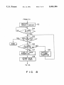
The image forming apparatus equipped with the
above IC cards 65-67 can be designed in such a way
that as shown in the ?owchart of FIG. 8. In FIG. 8, it
is discriminated in step S14 whether or not the RAM 52
becomes fully loaded while data is being down-loaded
from the host device 58 in step S2, and when the deci
sion is positive (YES), the 1C card 65, 66 or 67 in use can
be used as an extension memory to continue the down
loading (steps S15 and S18). In this case, the RAM
incorporated in the apparatus need not have a large
capacity, thus providing a low-cost and easy-to-operate
image forming apparatus ?exible in expanding a mem
ory. The memory expansion capability can be applied
not only data down-loading but also to a case of insuf?
cient memory for some other reasons.
Furthermore, a password or an ID number may be 50
said memory medium having said predetermined
tus, thereby executing initialization of said image
forming apparatus, wherein
said memory control means includes first means for
detecting whether said memory medium is blank or
not when the predetermined initialization data is
being written into said memory medium and sec
ond means for detecting whether rewriting of said
memory medium is permissible when it is detected
by the ?rst means that the memory medium is not
blank.
2. An image forming apparatus according to claim 1,
further comprising:
receiving means for receiving said memory medium;
second instruction means for giving a power supply
instruction to supply power to said memory me
dium set in said receiving means or a power stop
written in the IC cards 65-67 in advance so that the
instruction to stop power supply to said memory
operation advances to step S2 in FIG. 7 to permit the
use of the image forming apparatus only if the ID num
medium; and
power supply control means for controlling power
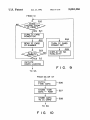
ber is found to be correct in steps S22 and S23 in FIG.
9. In this case, the total number of copies made may be
stored in the associated IC card 65, 66 or 67 and the
memory contents may be referred to using the opera
tion panel 9. This contributes to charging the user.
The IC cards 65-67 may also be provided with a
timer function so that in storing ?xed data such as for
mat data in the associated IC card, the date on which
the ?xed data is stored is also stored in the card as indi
cated in steps S26 and S27 in FIG. 10. This modi?cation
supply or stoppage of power supply to said mem
ory medium in accordance with the instructions
from said second instruction means,
whereby at a time said memory medium is set in or
removed from said receiving means, power to said
memory medium is cut off in response to the power
stop instruction from said second instruction
means, and whenv said memory medium is set in said
receiving means, power is given to said memory
medium in response to the power supply instruc
tion from said second instruction means.
permits the operator to con?rm the date of storage of
3. An image forming apparatus according to claim 1,
the data upon reading out the data from the associated 65
wherein said ?rst loading means includes a RAM and
IC card and easily discriminate how old the data is.
means for down loading data from said host device to
Accordingly, the operator can always update the copy
said memory medium when said RAM is fully loaded.
ing operationbased on the latest data.
9
5,083,286
wherein said memory medium includes an externally
provided memory medium.
7. An image forming apparatus according to claim 6,
memory medium.
5. An image forming apparatus according to claim 1,
wherein said memory medium includes a portable mem
ory medium.
wherein said memory medium has a timer function for
outputting time data and means for storing said time
data as well as the predetermined data from said load
memory means.
10
6. An image forming apparatus according to claim 1,
4. An image forming apparatus according to claim 1,
further comprising means for checking validity of said
8. An image forming apparatus according to claim 7,
wherein said portable memory medium includes an
integrated circuit (IC) card.
10
25
35
55
60
65
i
t
i
I
i
*
"