1
US007409175B2
(12) United States Patent
(10) Patent No.:
Kim et a].
(54)
(45) Date of Patent:
IMAGE FORMINGAPPARATUS AND IMAGE
5,191,376 A *
3/1993 Hayashi .................... .. 399/201
6,510,301 132*
UNIT FOR LOCKING MOVABLE OBJECT
6,768,887 B2 *
1/2003
7/2004
T311312 .... ..
Mikita et a1.
2003/0076545 A1*
4/2003
Liu
(21) Appl.No.: 11/340,792
(22) Filed:
* cited by examiner
(73) Assignee: Samsung Electronics Co., Ltd.,
SuWon-si (KR)
Notice:
Subject to any disclaimer, the term of this
patent is extended or adjusted under 35
U.S.C. 154(b) by 0 days.
Jan. 27, 2006
(65)
(30)
(KR)
Aug. 10, 2006
5/1984
10/1985
1/1989
11/1993
11/1998
6/1988
1/2001
4/2001
7/2003
12/2003
(74) Attorney, Agent, or FirmiStein, McEWen & Bui, LLP
(57)
.................... .. 10-2005-0011147
ABSTRACT
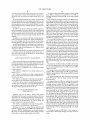
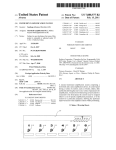
An image forming apparatus includes an image forming
body, a locking unit blocking movement of at least one mov
Int. Cl.
G03G 15/00
(2006.01)
(52)
US. Cl. ..................... .. 399/107; 399/110; 399/391;
(58)
Field of Classi?cation Search ............... .. 399/107,
399/393
399/110-125, 391-393
See application ?le for complete search history.
(56)
59-88727
60-211470
64-29829
5-294521
10-293431
1988-4356
2001-4136 A
2001-32466
2003-63100 A
2003-95139 A
Assistant ExamineriRuth N Labombard
Foreign Application Priority Data
Feb. 7, 2005
.......................... .. 358/474
Primary ExamineriDavid M. Gray
Prior Publication Data
US 2006/0177237 A1
References Cited
able object of the image forming body, and a control unit
controlling a locking state of the locking unit and a releasing
state of the locking unit. The locking unit includes a latching
member provided on one of the at least one movable object
and provided With a latching depression, a supporting mem
ber provided on the image forming body, and a locking mem
ber movably supported by the supporting member so as to be
insertable into and removable from the latching depression of
the latching member.
U.S. PATENT DOCUMENTS
5,157,448 A *
399/125
. .. 399/122
FOREIGN PATENT DOCUMENTS
JP
JP
JP
JP
JP
KR
KR
KR
KR
KR
(51)
Aug. 5, 2008
READINGAPPARATUS WITH LOCKING
(75) Inventors: Young-min Kim, SuWon-si (KR);
Sang-cheol Park, SuWon-si (KR)
(*)
US 7,409,175 B2
10/1992
Lang ......................... .. 399/23
25 Claims, 6 Drawing Sheets
US. Patent
Aug. 5, 2008
Sheet 1 of6
US 7,409,175 B2
US. Patent
Aug. 5, 2008
Sheet 2 of6
FIG. 2
(PRIOR ART)
US 7,409,175 B2
US. Patent
Aug. 5, 2008
Sheet 3 of6
US 7,409,175 B2
FIG. 3
(PRIOR ART)
4
US. Patent
Aug. 5, 2008
Sheet 5 of6
US 7,409,175 B2
FIG. 5A
3
t
mo /1.
MW
.3
0 W
313sa.
3/3 3 1|
.1/l3
2¢
31H/
w
m /,
ww
s
W
u
3(1
m
w
w}
a
5..
w
{0mw3
M“-I“a
mmw5om/V
\
?1. L.
w/
m
w
w
n
OV\J
\
0,
m
E
500/’
FIG. 5B
DRIVER
510-» CONTROLLER
soof
1\1
/%
u, w
US. Patent
Aug. 5, 2008
Sheet 6 of6
US 7,409,175 B2
FIG. 5C
550w
DR ! VER
ll
510w CONTROLLER
FIG. 5D
3338
3 53
M
7/A
/
/
mm
381
//
W avsm
\1\
H
510w CONTROLLER
soof
531 533 355
530
\
311
US 7,409,175 B2
1
2
IMAGE FORMING APPARATUS AND IMAGE
READING APPARATUS WITH LOCKING
UNIT FOR LOCKING MOVABLE OBJECT
A contact image sensor 4 is installed at a curved portion of
a conveyance path, and a document pressing roller 5d for
pressing and conveying the documents on the conveyance
path is installed opposite the contact image sensor 4. The
CROSS-REFERENCE TO RELATED
APPLICATIONS
document pressing roller 5d is elastically pressed by a press
spring Si in the direction of the conveyance path, and if a
document S enters the reading unit 6, the document S is
This application claims the bene?t of Korean Patent Appli
pressed by the document pressing roller 5d and conveyed
cation No. 2005-11147 ?led on Feb. 7, 2005, in the Korean
While being in contact With a document base glass 2a.
The image reading section 1s described above can operate
in either a ?at-bed mode in Which a stationary document is
read, or a sheet-through mode in Which a moving document is
read.
In the ?at-bed reading mode, a document B is placed on the
Intellectual Property O?ice, the disclosure of Which is incor
porated herein by reference.
BACKGROUND OF THE INVENTION
1. Field of the Invention
An aspect of the present invention relates to an image
document base glass 2a, and When the pressing plate 1 is
rotated about the hinge axis 1g, the document B is pressed
against the document base glass 2a. Then, the contact image
forming apparatus and an image reading apparatus. More
speci?cally, an aspect of the present invention relates to an
image forming apparatus and an image reading apparatus in
Which movable objects (for example, an image reading unit,
sensor 4 moves in the direction of the arroW A, and reads an
20
2a.
an opening/closing member, a recording material cassette,
and the like) are locked so as not to move When a product is
In the sheet-through reading mode, the contact image sen
shipped, and a locking structure is automatically released
When the product is unpacked and used for the ?rst time by a
user.
25
2. Description of the Related Art
Conventionally, apparatuses such as a digital photocopier,
sor 4 stands still at the position of the reading unit 6 and reads
an image of a moving document S. The documents S placed
on the document stacking tray 10 are ?rst conveyed by the
preliminary conveyance roller 1d and the preliminary con
veyance pressing panel 5a, and are then separated into indi
vidual sheets by the separating roller 1e that is in contact With
a facsimile machine, a printer, and a multifunction device
having an image reading section, an image forming section,
and an automatic document conveyer are knoWn.
image of the document B placed on the document base glass
the separating pad 5b. Thereafter, the documents S are con
30
The image reading section is a device for reading image
veyed to the reading unit 6 by the paper feed roller 50 against
Which the document feed roller If is pressed by the pressing
information of supplied documents, and the image forming
panel spring.
section is a device for printing images on recording materials
At the reading unit 6, the documents S are conveyed While
being in contact With a surface of the document pressing roller
5d, and images of the documents S are read by the contact
image sensor 4. The document pressing roller 5d is elastically
based on the image information read by the image reading
section. The automatic document conveyer is a device for
supplying documents one sheet at a time to a reading position
35
of the image reading section, and ejecting documents to a
document ejection tray after the documents have been read.
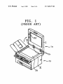
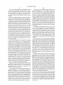
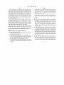
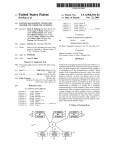
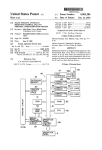
FIG. 1 shoWs a con?guration of a conventional image
forming apparatus disclosed in Japanese Unexamined Patent
40
Application Publication No. 10-293431 published on Nov. 4,
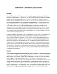
1998, and FIG. 2 is a perspective vieW shoWing a con?gura
tion of an image reading section of the image forming appa
With a locking device 20 that holds an image reading sensor,
such as the contact image sensor 4 described above, so that it
does not move.
ratus in FIG. 1.
Referring to FIG. 1, an image forming apparatus includes
an image reading section 1s for reading images of documents
S and B, and an image forming section 1p for forming images
pressed in the direction of the conveyance path by the press
spring 5i, and prevents the documents S from ?oating on the
document base glass 211.
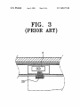
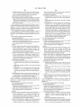
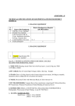
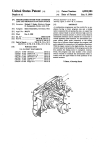
FIG. 3 shoWs an example of an image forming apparatus
45
The image forming apparatus in FIGS. 1-2 described above
uses a locking device 20 as shoWn in FIG. 3 to holdthe contact
image sensor 4 so that it does not move When the image
forming apparatus is shipped.
on recording materials based on the image information read
by the image reading section 1s.
Accordingly, a user can use the image reading section 1s
A pressing panel 1 is installed on a frame 2 With hinges 1h
to rotate through a certain angular range about a hinge axis 1g.
Referring to FIG. 2, a document stacking tray 10 is pro
vided on the top of the pressing panel 1 in order to stack
documents S. A document ejecting conveyer 5 is provided at
50
the upper portion of the pressing panel 1. The document
55
only after the locking device 20 is released. If the locking
device 20 is not released due to a user’s mistake, the image
reading section 1s cannot be used properly, and if serious
problems occur as a result, service must be called for.
ejecting conveyer 5 includes a preliminary conveyance roller
1d and a preliminary conveyance pressing panel 511 for con
Conventionally, only a locking device 20 for locking an
image reading sensor is provided. HoWever, an image form
ing apparatus includes several easily movable parts, such as
the pressing panel 1 and an opening/closing member for
veying the documents S from the document stacking tray 10,
opening/closing the image forming section 1p described
and a separating pad 5b and a separating roller 1e for sepa
above, a recording material cassette for supplying recording
rating the documents S that are conveyed by the preliminary
60
conveyance roller 1d and the preliminary conveyance press
ing panel 511 into individual sheets. In addition, the document
ejecting conveyer 5 includes a document feed roller if and a
paper feed roller 50 for feeding the documents S to a reading
unit 6, With the paper feed roller 50 being pressed against the
document feed roller if by a pressing panel spring (not
shoWn).
65
materials on Which images are printed based on the image
information read by the contact image sensor 4, and the like.
Therefore, in order to prevent the easily movable parts
described above from moving When the image forming appa
ratus is shipped, packing materials must be carefully selected,
and special ?xing materials must be additionally attached to
?x the easily movable parts in place to prevent them from
moving.
US 7,409,175 B2
3
4
SUMMARY OF THE INVENTION
A manual operating unit may be provided at an end portion
of the locking member to enable the locking member to be
operated manually, and the manual operating unit may be a
The present invention addresses the above drawbacks and/
or other problems in the related art. An aspect of the invention
tool socket corresponding to a manual tool.
The control unit may include a controller judging if a state
is to provide an image forming apparatus in Which a locking
unit Which locks an image reading unit is automatically
released When the image forming apparatus is used.
Another aspect of the invention is to provide an image
of the image forming apparatus is a state in Which the locking
unit is to be locked or a state in Which the locking unit is to be
objects other than the image reading unit are provided and are
released, a driving unit driving the locking unit, and a driver
operating the driving unit according to an output signal of the
controller if the controller judges the state of the image form
automatically released When the image forming apparatus is
ing apparatus to be a state in Which the locking unit is to be
used.
Another aspect of the invention is to provide an image
locked or a state in Which the locking unit is to be released.
forming apparatus in Which locking units for locking movable
The driving unit may include a motor generating a driving
force, a driving gear directly or indirectly connected to the
motor and rotatable in a locking direction to lock the locking
unit and a releasing direction to release the locking unit, and
a gear provided on the locking member and engaging the
forming apparatus in Which the amount of packing materials
required to ship the image forming apparatus is reduced by
using locking units for locking movable structures including
an image reading unit.
According to one aspect of the invention, an image forming
apparatus includes an image forming body, a locking unit
blocking movement of at least one movable object of the
driving gear.
The motor may be any one of motors that drive operating
20
image forming body, and a control unit controlling a locking
directly connected to the any one of the motors that drive the
operating units or may be connected to the any one of the
state of the locking unit and a releasing state of the locking
unit.
motors that drive the operating units through at least one relay
The at least one movable object may be any one or any
combination of an image reading unit reading images of
units in the image forming body, and the driving gear may be
25
gear.
The driving gear may rotate at a ?xed position in a linear
direction, and a thickness of the driving gear may be greater
than a thickness of the gear provided on the locking member.
documents, a cover installed on the image forming body so as
to be openable aWay from and closable against a top surface
of a document base glass on Which a document is to be placed,
The state of the image forming apparatus in Which the
a recording material cassette supplying recording materials
locking unit is to be released may be a state in Which poWer to
the image forming apparatus is turned on or a state in Which
on Which images are to be formedbased on the images read by
30
the image reading unit, the recording material cassette being
operating units in the image forming body are ready to start
operating, and the state of the image forming apparatus in
attachable to and removable from the image forming body, a
knock-up plate installed inside the recording material cassette
Which the locking unit is to be locked may be a state in Which
a locking command is set by a user.
on Which recording materials are to be stacked, a covering
member opening and closing the image forming body, a mul
tipurpose paper feed device feeding recording materials one
35
According to another aspect of the invention, an image
reading apparatus includes an image reading main body, a
material guide lining up recording materials stacked on the
document base glass installed on a top surface of the image
reading main body and having a top surface on Which docu
knock-up plate in a Width direction and/ or a length direction.
ments are to be placed in a stationary state and/or a moving
sheet at a time or performing other functions, and a recording
The covering member may be a rear cover installed on a 40
rear surface of the image forming body to replace a ?xing unit
installed inside the image forming body and/ or to remove
jammed recording materials from inside the image forming
body, and/or a top cover installed on a top surface of the image
forming body to replace a developing unit installed inside the
45
image forming body and/or to remove jammed recording
materials from inside the image forming body.
The locking unit may include a latching member provided
50
image forming body, and a locking member movably sup
and removable from the latching depression of the latching
movable object to alloW the movable object to move, and a
control unit to control the controllable locking unit to selec
member.
55
tively lock and release the movable object.
According to another aspect of the invention, an image
reading apparatus includes an image reading main body, a
document base glass disposed on the main body on Which a
document is to be placed, an image reading unit disposed in
only up to a point that is a certain distance aWay from an end
of the latching depression.
able object disposed in the image forming body, a control
lable locking unit to selectively lock the movable object to
prevent the movable object from moving and release the
ported by the supporting member so as to be insertable into
The latching depression may have nut threads formed
therein, and an end portion of the locking member may have
bolt threads corresponding to the nut threads formed thereon.
The nut threads may be formed in the latching depression
document glass, a cover installed on the image reading main
body so as to be openable aWay from and closable against the
top surface of the document base glass, a locking unit block
ing movement of the image reading unit or the cover, and a
control unit controlling a locking state of the locking unit and
a releasing state of the locking unit.
According to another aspect of the invention, an image
forming apparatus includes an image forming body, a mov
on one of the at least one movable object and provided With a
latching depression, a supporting member provided on the
state, an image reading unit installed facing the document
base glass reading images of the documents placed on the
60
the image reading main body facing the document base glass
The supporting member may be provided on the image
forming body facing the latching member across a certain gap
and being movable relative to the document base glass to read
and may include a supporting frame provided With a support
ing hole through Which the locking member passes so as to be
cover disposed on the image forming body and being open
able aWay from and closable against the document base glass,
a controllable locking unit to selectively lock the image read
supported by the supporting frame of the supporting member,
and an elastic member may be provided betWeen a portion of
the latching member and the supporting frame.
an image of a document placed on the document base glass, a
65
ing unit or the cover to prevent the image reading unit or the
cover from moving and release the image reading unit or the
US 7,409, l 75 B2
6
5
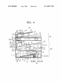
The image reading section 100S includes an image reading
cover to allow the image reading unit or the cover to move,
and a control unit to control the controllable locking unit to
frame 10211, a document base glass 103, a cover 105, an
selectively lock and release the image reading unit or the
automatic document feeding unit 120, and an image reading
cover.
unit 109.
More speci?cally, the image reading section 100S includes
In an image forming apparatus according to an aspect of the
invention described above, the locking units used to prevent
movable objects from moving during shipping of the image
the image reading frame 10211 as a portion of an image form
ing body 102. The document base glass 103 is installed on top
forming apparatus need not be manually released by a user,
of the image reading frame 102a, and the image reading unit
thereby making the image forming apparatus convenient for
109 is installed so as to read an image of a document D3
the user to use.
supplied through the automatic document feeding unit 120
In addition, the amount of packing materials required to
prevent movement of movable objects in the image forming
after being moved to a predetermined position inside the
apparatus is reduced, thereby decreasing the consumption of
image reading frame 10211, or to read an image of a document
D4 resting on the upper surface of the document base glass
packing materials Which Will be throWn aWay and reducing
the space required to pack the image forming apparatus for
the document base glass 103, or to rest at a home position
103 by moving rectilinearly and reciprocally in parallel With
inside the image reading frame 10211 When the image reading
shipping.
unit 109 is not reading an image.
In addition, a user cannot use the image forming apparatus
Without releasing the locking units, thereby eliminating ser
The cover 105 is installed so as to be openable aWay from
vice calls resulting from the user trying to use the image
forming apparatus Without ?rst releasing the locking units.
20
In addition, relocking of the locking units can be performed
as needed, thereby alloWing reuse of the locking units When
moving the image forming apparatus to a different place
The automatic document feeding unit 120 includes a docu
ment stacking tray 121 for stacking documents D3, rollers
123a, 123b, 1230 for picking up, conveying, and ejecting
Where it is to be used.
Additional aspects and/or advantages of the invention Will
be set forth in part in the description Which folloWs and, in
part, Will be obvious from the description, or may be learned
25
by practice of the invention.
BRIEF DESCRIPTION OF THE DRAWINGS
30
These and/or other aspects and advantages of the invention
Will become apparent and more readily appreciated from the
folloWing description of the embodiments, taken in conjunc
The automatic document feeding unit 120 is provided at
35
40
opened and closed.
The image forming section 100P includes an image form
ing frame 102b, a paper feeding unit 130, an image forming
unit 150, a transferring unit 170, a ?xing unit 180, and a paper
ejecting unit 190.
The image forming frame 102!) forms the image forming
body 102 together With the image reading frame 102a
With a locking device that holds an image reading sensor so
that it does not move;
45
described above.
The paper feeding unit 130 is for supplying the recording
materials 101 to the image forming unit 150 and includes a
recording material cassette 131 that is attachable to and
removable from the image forming frame 102b, and a knock
movable object locking units of an image forming apparatus
according to an aspect of the invention Which may be used in
the image forming apparatus shoWn in FIG. 4.
one side of the upper portion of the cover 105, and is mounted
so as to move together With the cover 105 as the cover 105 is
FIG. 1 shoWs a con?guration of a conventional image
forming apparatus;
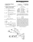
FIG. 4 shoWs a con?guration of an image forming appara
tus according to one embodiment of the invention; and
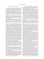
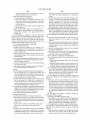
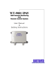
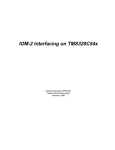
FIGS. 5A to 5D are vieWs for explaining the operation of
documents D3 from the document stacking tray 121, and a
document ejection tray 125 for stacking documents D3 after
they have been ejected. The roller 12311 is a pickup roller for
picking up the documents D3 stacked in the document stack
ing tray 121, the roller 12319 is a conveyance roller for con
veying the picked up documents D3 to the document base
glass 103, and the roller 1230 is an ejection roller for ejecting
the conveyed documents D3 to the document ejection tray
125.
tion With the accompanying draWings of Which:
FIG. 2 shoWs a con?guration of an image reading section
shoWn in FIG. 1;
FIG. 3 shoWs an example of an image forming apparatus
and closable against the top surface of the document base
glass 103, and presses the upper surface of the document D4
resting on the upper surface of the document base glass 103.
50
up plate 135 that is provided in the recording material cassette
131 Where it can move up and doWn and is elastically sup
DETAILED DESCRIPTION OF THE
EMBODIMENTS
Reference Will noW be made in detail to the present
ported upWardly by an elastic member 133, and has the
55
recording materials 101 stacked on its top surface. In addi
tion, the paper feeding unit 130 includes a pickup roller 137
for picking up the recording materials 101 stacked on the
60
knock-up plate 135, and a feed roller 138 for feeding the
recording materials 101 picked up by the pickup roller 137 to
the image forming unit 150. The recording material cassette
131 is additionally provided With a recording material guide
139 for lining up the side edges of the recording materials 101
embodiments of the present invention, examples of Which are
illustrated in the accompanying draWings, Wherein like ref
erence numerals refer to the like elements throughout. The
embodiments are described beloW in order to explain the
present invention by referring to the ?gures.
stacked on the knock-up plate 135 in the Width direction. The
recording material guide 139 may also be formed so as to line
FIG. 4 shoWs a con?guration of an image forming appara
tus according to one embodiment of the invention.
Referring to FIG. 4, an image forming apparatus 100
includes an image reading section 100S, and an image form
ing section 100P for forming images on recording materials
101 using an electrophotographic method based on image
information read by the image reading section 100S.
up the end edges of the recording materials 101 in the length
65
direction.
The image forming unit 150 forms a toner image on a
photoconductor 151 through charging, exposing, and devel
oping.
US 7,409,175 B2
7
8
The image forming unit 150 includes a cartridge 152, a
charging roller 153 for charging the surface of the photocon
ductor 151, a laser beam scanning unit 155 for scanning a
laser beam across the charged surface of the photoconductor
211 and the ?xing motor 213 may be formed in one body, or
the ?xing motor 213 and the paper ejecting motor 215 may be
formed in one body.
The image forming apparatus 100 described above is addi
tionally provided With a locking unit for locking movable
151 to form an electrostatic latent image on the photoconduc
objects.
tor 151, and a developing roller 157 for developing the elec
trostatic latent image formed on the photoconductor 151
using toner to form a toner image on the photoconductor 151.
The developing roller is in contact With the surface of the
A movable object to be locked may be any one of the image
reading unit 109 that moves rectilinearly and reciprocally
inside the image reading frame 10211 of the image forming
body 102, the cover 105 that is openable aWay from and
closable against the document base glass 103, and the open
photoconductor 151 and rotates so as to apply the toner to the
surface of the photoconductor 151.
The transferring unit 170 includes a transferring roller 171
that rotates While contacting the photoconductor 151 to trans
ing/clo sing members for opening and closing the image form
ing body 102 such as the multipurpose paper feed device 201,
fer the toner image formed on the photoconductor 151 onto
the top cover 203, and the rear cover 205. In addition, a
the recording materials 101.
The ?xing unit 180 is for ?xing the toner image transferred
by the transferring roller 171 of the transferring unit 170 on
the recording materials 101, and includes a heating roller 181
movable object to be locked may be any one of the recording
material cassette 131 that is attachable to and removable from
the image forming frame 102!) of the image forming body
102, the knock-up plate 133 provided in the recording mate
that is heated to a high temperature, and a pressing roller 183
that rotates While contacting the heating roller 181. The
recording materials 101 are conveyed betWeen the heating
rial cassette 131 that can move up and doWn and is elastically
20
roller 181 and the pressing roller 183 to ?x the toner image on
the recording materials 101.
The paper ejecting unit 190 ejects the recording materials
1 01 on Which the toner image has been ?xed by the ?xing unit
180 onto a paper ejecting plate 191 that is provided outside
locked are not limited to the structures described above, but
diverse structures such as a double-sided paper feed device or
25
the image forming frame 102b, and includes paper ejecting
rollers 193a, 193b, 1930.
A multipurpose paper feed device 201 for supplying
recording materials one sheet at a time or for performing other
30
functions is installed at one side of the image forming frame
102b in an opening and closing manner. A top cover 203 for
replacing the image forming unit 150 or removing jammed
recording materials is installed at one side of the image form
ing frame 102!) adjacent to the paper ejecting plate 191 in an
35
FIGS. 5A to 5D are vieWs for explaining the operation of
40
Various ones of the rollers described above are directly
45
and a scanning motor 217 are shoWn in FIG. 4.
according to an aspect of the invention.
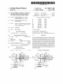
Referring to FIGS. 5A to 5D, a locking unit 300 and a
tions of the locking unit 300 are depicted.
A locking unit 300 includes a latching member 310 that is
provided on the movable objects described above and has a
latching depression 311, a supporting member 330 that is
provided on the image forming body 102 (i.e., on the image
reading frame 10211 or the image forming frame 10219), and a
50
locking member 350 that is movably supported by the sup
porting member 330 so as to be insertable into or removable
from the latching depression 311 of the latching member 310.
The latching depression 311 has nut threads 313 formed
therein, and the end portion of the locking member 350 has
180.
motor 215, and the scanning motor 217 are provided. HoW
ever, the invention is not limited to this example, but the
number of motors may be decreased or increased by provid
ing the motors in diverse forms. For example, the main motor
movable object locking units of an image forming apparatus
control unit 500 for controlling locking and releasing opera
connected to a motor, or are connected to a motor through
The paper ejecting motor 215 supplies poWer for driving
the paper ejecting rollers 193a, 193b, 1930. The paper eject
ing motor 215 may also drive a fan (not shoWn) for exhausting
heat generated inside the image forming frame 102!) by the
?xing unit 180 Which operates at a high temperature.
The scanning motor 217 supplies poWer for moving the
image reading unit 109 rectilinearly and reciprocally in par
allel With the document base glass 103.
In the image forming apparatus 100 described above, the
main motor 211, the ?xing motor 213, the paper ejecting
L1-L4 in FIG. 4 denotes the portions of the image forming
applied.
180 or removing jammed recording materials.
The main motor 211 primarily supplies poWer for driving
the pickup roller 137, the feed roller 138, the photoconductor
151, the developing roller 157, the charging roller 153, and
the transferring roller 171.
The ?xing motor 213 supplies poWer for driving the heat
ing roller 181 and the pressing roller 183 of the ?xing unit
Such movable objects are easily moved When image form
ing apparatus 100 is shipped or moved, and can be easily
broken in such circumstances. Therefore, an aspect of the
present invention is an image forming apparatus 100 in Which
movable objects are locked When the image forming appara
apparatus 100 to Which the locking unit referred to above is
the other side of the image forming frame 102!) in an opening
and closing manner, that is, at the opposite side of the image
forming frame 102!) from the multipurpose paper feed device
relay gears, in order to receive poWer from the motor. A main
motor 211, a ?xing motor 213, a paper ejecting motor 215,
a supplemental paper feed device may also be a movable
object to be locked. Any combination of tWo or more of the
structures described above may be movable objects to be
locked.
tus 100 is shipped or moved, and are automatically unlocked
When a user uses the image forming apparatus 100.
opening and closing manner. A rear cover 205 is installed at
201. The rear cover 205 is used for replacing the ?xing unit
supported upWardly, or the recording material guide 139 for
lining up the recording materials 101. Movable objects to be
55
bolt threads 353 corresponding to the nut threads 313 formed
thereon. The nut threads 313 are preferably formed in the
latching depression 311 only up to a point that is a certain
distance H aWay from the end of the latching depression 311
so that the locking member 350 can be easily removed from
60
the latching depression 311.
The supporting member 330 is provided on the image
forming body (the image reading frame 10211 or the image
forming frame 10219) facing the latching member 310 across
a certain gap, and includes supporting frames 331, 333 pro
65
vided With supporting holes 331a, 33311 through Which the
locking member 350 passes so as to be supported by the
supporting frames 331, 333 of the supporting member 330.
US 7,409,175 B2
10
A state of the image forming apparatus 100 Which the
The control unit 500 includes a controller 510 for judging
if a state of the image forming apparatus 100 is a state in
Which the locking unit 300 is to be locked or a state in Which
the locking unit 300 is to be released, a driving unit 530 for
move and reinstall the image forming apparatus 100. In this
driving the locking member 350, and a driver 550 for receiv
ing a signal from the controller 510 and driving the driving
state, if the user selects a locking function through an opera
tion such as pressing a locking button provided in an operat
unit 530.
The driving unit 530 includes a motor 531 for generating a
driving force, a driving gear 533 that rotates When it receives
the driving force from the motor 531, and a gear 355 that is
locking unit 300 is relocked. In the example of the locking
unit 300 described above, the relocking is accomplished by
rotating the driving gear 533 described above in the locking
controller 510 judges to be a state in Which the locking unit
300 is to be locked may be a state in Which a user desires to
ing unit for operating the image forming apparatus 100, the
direction opposite to the releasing direction to move the lock
ing member 350 toWard the latching member 3 10 in the linear
formed on the outer surface of the locking member 350 so as
to engage and be rotated by the driving gear 533. The driving
direction so as to insert the locking member 350 into the
latching member 310 and screW the bolt threads 353 on the
gear 533 may be directly connected to the motor 531 so as to
directly receive the driving force from the motor 531, or may
receive the driving force indirectly from the motor 531
through a relay gear train. If a relay gear train is used, the
locking member 350 into the nut threads 313 of the latching
motor 531 can be replaced by a motor for driving one or more
of the operating units of the image forming apparatus 100.
The motor for driving one or more of the operating units may
be the main motor 211, the ?xing motor 213, the paper eject
ing motor 215, the scanning motor 217, or any other motor
provided for driving one or more of the operating units. FIG.
4 is an example shoWing the top cover 203 and the multipur
pose paper feed device 201 being connected to the main
motor 211 through a relay gear train 210. Any combination of
20
locking member 350. The manual operator 357 is preferably
formed by a tool socket 357a corresponding to a manual tool
358. The manual operator 357 may be formed so as to be
operated simply by hand Without using the manual tool 358.
25
tWo or more of the motors described above may be used to
replace the motors 531 in any combination of tWo or more of
direction, and the thickness tl of the driving gear 533 is
preferably greater than the thickness t2 of the gear 355. The
reason for this is to enable the driving gear 533 to guide the
30
ing gear 533. The gear 355 moves aWay from the latching
member 310 in the linear direction When the driving gear 533
350 have been screWed into the nut threads 3 13 of the latching
35
latching member 310. As a matter of course, diverse gears
rear cover 205, the recording material cassette 131, the
knock-up plate 133, the recording material guide 139, and the
like) cannot move, thereby achieving the locking state.
Accordingly, When the image forming apparatus 100 is
rotates in a releasing direction as a result of the bolt threads
353 of the locking member 350 unscreWing from the nut
threads 313 of the latching member 310, and moves toWard
the latching member 310 in the linear direction When the
driving gear 533 rotates in a locking direction opposite to the
releasing direction as a result of the bolt threads 353 of the
locking member 350 screWing into the nut threads 313 of the
been inserted into the latching depression 311 of the latching
member 310, and the bolt threads 353 of the locking member
member 310 so that movable objects in the image forming
apparatus 100 (the image reading unit 109, the cover 105, the
multipurpose paper feed device 201, the top cover 203, the
gear 355 so that the gear 355 moves a certain distance in the
linear direction While engaging and being rotated by the driv
The operation of the locking unit 300 described above Will
be explained beloW With an example of releasing the locking
unit 300.
First, as shoWn in FIG. 5A, the locking member 350 has
the locking units 300.
The driving gear 533 rotates at a ?xed position in a linear
member 310.
The locking member 350 described above may be formed
so as to be operated manually after a user thoroughly learns
hoW to release it by reading a user’s manual. For this purpose,
a manual operator 357 is provided at the end portion of the
40
shipped and moved, the movable objects do not move,
thereby maintaining the image forming apparatus 100 in a
stable state.
45
such as a bevel gear, a helical gear, a rack-and-pinion gear, a
Thereafter, as shoWn in FIGS. 5B and 5C, if a userperfor'ms
an operation such as pressing a poWer sWitch, the controller
510 judges that this state is a state in Which the locking unit
300, is to be released and outputs a driving signal to the driver
550. Then, the driver 550 drives the driving unit 530 accord
ing to the signal received by the driver 550 from the controller
spur gear, or any other suitable type of gear may be applied to
both the gear 355 and the driving gear 533, taking into con
sideration the direction of the driving axis and the engage
ment ratio of the gear 355 and the driving gear 533.
In addition, an elastic member 381 is provided betWeen the
gear 355 and the supporting frame 333. The elastic member
381 applies an elastic force betWeen the gear 355 and the
supporting frame 333, Which acts as a releasing force for
50
releasing the locking member 350.
55
510. Considering the driving operation in detail, When the
motor 531 is driven, the drive driving gear 533 rotates in the
releasing direction, and the gear 355 engaging the driving
gear 533 is accordingly rotated by the driving gear 533 . At this
point, the driving gear 533 rotates in the releasing direction at
the ?xed position in the linear direction, so that the locking
member 350 moves aWay from the latching member 310 in
the linear direction While the gear 355 is engaging and being
A state of the image forming apparatus 100 Which the
rotated by the driving gear 533 as a result of the bolt threads
controller 510 judges to be a state in Which the locking unit
353 of the locking member 350 unscreWing from the nut
threads 313 of the latching member 310.
Then, as shoWn in FIG. 5D, When the locking member 350
has moved aWay from the latching member 310 in the linear
direction until it has reached a point Where the gear 355 is
300 is to be released may be a certain standby state such as a
standby state in Which poWer to the image forming apparatus
100 is turned on, or a standby state in Which each operating
60
unit, e.g., the paper feeding unit 130, the image reading unit
109, the image forming unit 150, the ?xing unit 180, the paper
ejecting unit 190, and the like, is ready to start operating. The
standby state in Which each operating unit is ready to start
operating may be a standby state in Which image reading is
possible, a standby state in Which printing is possible, or a
standby state in Which each operating unit is warmed up.
separated from the driving gear 533, the locking member 350
is removed from the latching depression 311 by the elastic
force of the elastic member 381, so that the locking unit 300
65
is released, thereby enabling the latching member 3 10 and the
movable object on Which the latching member 310 is pro
vided to move.
US 7,409,175 B2
11
12
FIGS. 5A through 5D explain the operation of the locking
Although a feW embodiments of the present invention have
unit 300 as applied to the image reading unit 109 to lock the
been shoWn and described, it Would be appreciated by those
image reading unit 109 in place at the home position inside
skilled in the art that changes may be made in these embodi
the image reading frame 102a. FIG. 5D shoWs a state Where
the locking unit 300 has been released and the latching mem
ber 310 and the image reading unit 109 on Which the latching
ments Without departing from the principles and spirit of the
invention, the scope of Which is de?ned in the claims and their
equivalents.
member 310 is provided have moved aWay from the locking
member 350 and the home position of the image reading unit
109 inside the image reading frame 10211 as the image reading
What is claimed is:
1. An image forming apparatus comprising:
an image forming body;
unit 109 begins an image reading operation.
After the image reading unit 109 has completed the image
reading operation, the image reading unit 109 returns to the
home position inside the image reading frame 10211 Where the
latching depression 311 of the latching member 310 provided
on the image reading unit 109 is aligned With the locking
a locking unit blocking movement of at least one movable
object of the image forming body; and
a control unit controlling a locking state of the locking unit
and a releasing state of the locking unit;
Wherein:
the control unit automatically releases the locking unit so
that the locking unit is in a released state before the
member 350. In this state, if the user selects the locking
function through an operation such as pressing the locking
image forming body begins forming an image, and
button provided in the operating unit for operating the image
maintains the locking unit in the released state While the
image forming body is forming the image;
forming apparatus 100, the locking unit 300 is relocked as
described above, thereby locking the image reading unit 109
20
in place at the home position inside the image reading frame
the control unit relocks the locking unit so that the locking
unit is once again in a locked state in response to a
102a.
locking command set by a user after the locking unit has
When the locking unit 300 is an unlocked state, the locking
member 350 is held aWay from the latching depression 311 of
the latching member 310 by the elastic force of the elastic
member 381. Therefore, before the locking unit 300 can be
relocked, the locking member 350 must be reinserted in the
latching depression 311 of the latching member 310 so that
been in the released state as a result of the control unit
the bolt threads 353 on the locking member 350 can engage
the nut threads 313 of the latching member 310. One Way of
accomplishing this is to use a pressing device (not shoWn) to
automatically releasing the locking unit; and
25
30
311 of the latching member 310. One example of such a
pressing device is a solenoid With a plunger that presses the
locking member 350 into the latching depression 311 of the
latching member 310 When the solenoid is energiZed. HoW
ever, any suitable pres sing device may be used. Alternatively,
the user may manually press the locking member 350 into the
latching depression 3 11 of the latching member 31 0 using, for
35
example, either the manual tool 358 or one of the user’s
40
and closable against a top surface of a document base glass on
Which a document is to be placed, a recording material cas
sette supplying recording materials on Which images are to be
formed based on the images read by the image reading unit,
the recording material cassette being attachable to and
removable from the image forming body, a knock-up plate
?ngers.
installed inside the recording material cassette on Which
recording materials are to be stacked, a covering member
opening and closing the image forming body, a multipurpose
When the locking unit 300 is applied to a movable object
paper feed device feeding recording materials one sheet at a
time or performing other functions, and a recording material
that can be opened and closed, such as the cover 105, the
aligned With the locking member 350 When the movable
object is closed to enable the locking unit 300 to be relocked.
When the locking unit 300 is applied to a movable object
one movable object is any one or any combination of an image
reading unit reading images of documents, a cover installed
on the image forming body so as to be openable aWay from
press the locking member 350 into the latching depression
multipurpose paper feed device 201, the top cover 203, and
the rear cover 205, the latching member 310 and the locking
member 350 are disposed so that the latching depression 311
of the latching member 3 1 0 provided on the movable object is
the locking unit comprises tWo threaded members that are
engaged With one another When the locking unit is in the
locked state, and that are disengaged from one another
When the locking unit is in the released state.
2. The apparatus as claimed in claim 1, Wherein the at least
guide lining up recording materials stacked on the knock-up
45
plate in a Width direction and/ or a length direction.
3. The apparatus as claimed in claim 2, Wherein the cover
ing member is a rear cover installed on a rear surface of the
50
image forming body to replace a ?xing unit installed inside
the image forming body and/ or to remove jammed recording
materials from inside the image forming body, and/or a top
that can be attached to or detached from the image forming
cover installed on a top surface of the image forming body to
apparatus 100, such as the recording material cassette 131,
the latching member 310 and the locking member 350 are
disposed so that the latching depression 311 of the latching
member 310 provided on the movable object is aligned With
the locking member 350 When the movable object is attached
to the image forming apparatus to enable the locking unit 300
replace a developing unit installed inside the image forming
body and/or to remove jammed recording materials from
inside the image forming body.
55
the tWo threaded members of the locking unit comprise:
to be relocked.
When the locking unit 300 is applied to a movable object
that can be moved to different positions, such as the knock-up
plate 133 provided in the recording material cassette 131 and
the recording material guide 139, the latching member 310
and the locking member 350 are disposed so that the latching
depression 311 of the latching member 310 provided on the
movable object is aligned With the locking member 350 When
the movable object is at a predetermined position to enable
the locking unit 300 to be relocked.
4. The apparatus as claimed in claim 1, Wherein:
the locking unit further comprises supporting member pro
vided on the image forming body; and
a threaded latching member provided on one of the at
60
least one movable object and provided With a threaded
latching depression; and
a threaded locking member movably supported by the
supporting member so as to be insertable into and
65
removable from the threaded latching depression of
the threaded latching member.
5. The apparatus as claimed in claim 1, Wherein the control
unit comprises:
US 7,409,175 B2
14
13
a controller judging if a state of the image forming appa
been in the released state as a result of the control unit
automatically releasing the locking unit;
ratus is a state in Which the locking unit is to be locked or
the locking unit comprises:
a state in Which the locking unit is to be released;
a driving unit driving the locking unit; and
a latching member provided on one of the at least one
movable object and provided With a latching depres
a driver operating the driving unit according to an output
signal of the controller if the controller judges the state
of the image forming apparatus to be a state in Which the
sion;
a supporting member provided on the image forming
locking unit is to be locked or a state in Which the locking
unit is to be released.
6. The apparatus as claimed in claim 5, Wherein a state of
body; and
a locking member movably supported by the supporting
the image forming apparatus in Which the locking unit is to be
from the latching depression of the latching member;
released is a state in Which poWer to the image forming
apparatus is turned on or a state in Which operating units in the
and the supporting member is provided on the image
forming body facing the latching member across a
certain gap and comprises a supporting frame pro
vided With a supporting hole through Which the lock
member so as to be insertable into and removable
image forming body are ready to start operating.
7. The apparatus as claimed in claim 5, Wherein a state of
the image forming apparatus in Which the locking unit is to be
ing member passes so as to be supported by the sup
locked is a state in Which the locking command is set by the
porting frame of the supporting member, and an
elastic member is provided betWeen a portion of the
latching member and the supporting frame.
user.
8. An image forming apparatus comprising:
an image forming body;
20
a locking unit blocking movement of at least one movable
object of the image forming body; and
a control unit controlling a locking state of the locking unit
and a releasing state of the locking unit;
Wherein:
the control unit automatically releases the locking unit so
that the locking unit is in a released state before the
a locking unit blocking movement of at least one movable
object of the image forming body; and
25
image forming body begins forming an image, and
a control unit controlling a locking state of the locking unit
and a releasing state of the locking unit;
Wherein:
the control unit automatically releases the locking unit so
that the locking unit is in a released state before the
image forming body begins forming an image, and
maintains the locking unit in the released state While the
image forming body is forming the image;
11. An image forming apparatus comprising:
an image forming body;
30
maintains the locking unit in the released state While the
image forming body is forming the image;
the control unit relocks the locking unit so that the locking
unit is once again in a locked state in response to a
the control unit relocks the locking unit so that the locking
locking command set by a user after the locking unit has
unit is once again in a locked state in response to a
locking command set by a user after the locking unit has
been in the released state as a result of the control unit
automatically releasing the locking unit;
35
automatically releasing the locking unit;
the locking unit comprises:
the locking unit comprises:
a latching member provided on one of the at least one
movable object and provided With a latching depres
a latching member provided on one of the at least one
movable object and provided With a latching depres
sion;
a supporting member provided on the image forming
been in the released state as a result of the control unit
40
body; and
a locking member movably supported by the supporting
sion;
a supporting member provided on the image forming
member so as to be insertable into and removable
body; and
a locking member movably supported by the supporting
from the latching depression of the latching member;
member so as to be insertable into and removable
and
from the latching depression of the latching member;
the latching depression has nut threads formed therein, and
an end portion of the locking member has bolt threads
corresponding to the nut threads formed thereon.
9. The apparatus as claimed in claim 8, Wherein the nut
threads are formed in the latching depression only up to a
point that is a certain distance aWay from an end of the
and
a manual operating unit is provided at an end portion of the
locking member to enable the locking member to be
operated manually.
50
latching depression.
13. An image forming apparatus comprising:
an image forming body;
10. An image forming apparatus comprising:
an image forming body;
a locking unit blocking movement of at least one movable
55
a locking unit blocking movement of at least one movable
object of the image forming body; and
object of the image forming body; and
a control unit controlling a locking state of the locking unit
and a releasing state of the locking unit;
Wherein:
the control unit automatically releases the locking unit so
that the locking unit is in a released state before the
12. The apparatus as claimed in claim 11, Wherein the
manual operating unit is a tool socket corresponding to a
manual tool.
a control unit controlling a locking state of the locking unit
and a releasing state of the locking unit;
Wherein the control unit comprises:
60
a controller judging if a state of the image forming
apparatus is a state in Which the locking unit is to be
image forming body begins forming an image, and
locked or a state in Which the locking unit is to be
maintains the locking unit in the released state While the
released;
image forming body is forming the image;
the control unit relocks the locking unit so that the locking
unit is once again in a locked state in response to a
locking command set by a user after the locking unit has
a driving unit driving the locking unit; and
65
a driver operating the driving unit according to an output
signal of the controller if the controller judges the
state of the image forming apparatus to be a state in
US 7,409,175 B2
15
16
maintain the controllable locking unit in the released
Which the locking unit is to be locked or a state in
state While the image forming body is forming the
Which the locking unit is to be released;
image;
Wherein the driving unit comprises:
the control unit controls the controllable locking unit to
relock the movable object so that the controllable lock
a motor generating a driving force;
a driving gear directly or indirectly connected to the
motor and rotatable in a locking direction to lock the
locking unit and a releasing direction to release the
ing unit is once again in a locked state in response to a
locking command set by a user after the controllable
locking unit has been in the released state as a result of
locking unit; and
the control unit automatically controlling the control
lable locking unit to release the movable object; and
a gear provided on the locking unit and engaging the
driving gear; and
Wherein the driving gear rotates at a ?xed position in a
linear direction, and a thickness of the driving gear is
greater than a thickness of the gear provided on the
locking unit.
14. The apparatus as claimed in claim 13, Wherein the
motor is any one of motors that drive operating units in the
15
ing:
a plurality of operating units disposed in the image forming
image forming body, and the driving gear is directly con
body that cooperate to form an image on a recording
nected to the any one of the motors that drive the operating
units or is connected to the any one of the motors that drive the
operating units through at least one relay gear.
material;
20
being attachable to and removable from the image form
ing body; and
a document base glass installed on a top surface of the
image reading main body and having a top surface on
at least one covering member to open and close an opening
25
one of the at least one covering member.
30
a cover installed on the image reading mainbody so as to be
a threaded latching member disposed on the movable
of the document base glass;
a locking unit blocking movement of the image reading
unit or the cover; and
18. The apparatus as claimed in claim 16, Wherein:
the tWo threaded members of the controllable locking unit
comprise:
openable aWay from and closable against the top surface
a control unit controlling a locking state of the locking unit
and a releasing state of the locking unit;
Wherein:
the control unit automatically releases the locking unit so
that the locking unit is in a released state before the
in the image forming body;
Wherein the movable object is one of the operating units, or
one of the at least one recording material supply unit, or
an image reading unit installed facing the document base
glass reading images of the documents placed on the
document glass;
at least one recording material supply unit to supply the
recording material, the recording material supply unit
15. An image reading apparatus comprising:
an image reading main body;
Which documents are to be placed in a stationary state
and/or a moving state;
the controllable locking unit comprises tWo threaded mem
bers that are engaged With one another When the locking
unit is in the locked state, and that are disengaged from
one another When the locking unit is in the released state.
17. The apparatus as claimed in claim 16, further compris
object; and
35
40
image reading unit begins reading an image, and main
a threaded locking member movably disposed in the
image forming body to be selectively lockable to and
releasable from the threaded latching member; and
the controllable locking unit further comprises a driving
unit to drive the threaded locking member to selectively
lock to and release from the threaded latching member,
thereby causing the controllable locking unit to selec
tively lock and release the movable object.
19. The apparatus as claimed in claim 18, Wherein the
driving unit comprises a motor coupled to the locking mem
tains the locking unit in the released state While the
image reading unit is reading the image;
ber; and
the control unit relocks the locking unit so that the locking
unit is once again in a locked state in response to a 45
Wherein the control unit controls the motor to operate in a
locking command set by a user after the locking unit has
locking direction to drive the locking member to lock to
been in the released state as a result of the control unit
the latching member, thereby controlling the control
automatically releasing the locking unit; and
lable locking unit to lock the movable object, and con
trols the motor to operate in a releasing direction oppo
the locking unit comprises tWo threaded members that are
engaged With one another When the locking unit is in the
locked state, and that are disengaged from one another
When the locking unit is in the released state.
16. An image forming apparatus comprising:
an image forming body;
a movable object disposed in the image forming body;
50
the controllable locking unit to release the movable
object.
20. The apparatus as claimed in claim 19, Wherein the
55
object to prevent the movable object from moving and
release the movable object to alloW the movable object
60
a control unit to control the controllable locking unit to
image forming body begins forming an image, and to
releasing operation of the controllable locking unit.
21. The apparatus as claimed in claim 19, further compris
selectively lock and release the movable object;
Wherein:
the control unit automatically controls the controllable
locking unit to release the movable object so that the
controllable locking unit is in a released state before the
driving unit further comprises:
a driving gear coupled to the motor; and
a gear disposed on the locking member and engaging the
driving gear during at least a portion of a locking opera
tion of the controllable locking unit and a portion of a
a controllable locking unit to selectively lock the movable
to move; and
site to the locking direction to drive the locking member
to release from the latching member, thereby controlling
ing a plurality of operating units disposed in the image form
ing body that cooperate to form an image on a recording
material;
65
Wherein the motor is coupled to the locking member and at
least one of the operating units to drive the locking
member and the at least one of the operating units.
US 7,409,175 B2
17
18
a controllable locking unit to selectively lock the image
reading unit or the cover to prevent the image reading
22. The apparatus as claimed in claim 16, wherein the
control unit monitors a state of the image forming apparatus,
controls the controllable locking unit to lock the movable
unit or the cover from moving and release the image
reading unit or the cover to alloW the image reading unit
object if the control unit judges that the state of the image
forming apparatus is a state in Which the movable object is to
be locked, and controls the controllable locking unit to release
the movable object if the control unit judges that the state of
the image forming apparatus is a state in Which the movable
object is to be released.
or the cover to move; and
a control unit to control the controllable locking unit to
selectively lock and release the image reading unit or the
cover;
Wherein:
the control unit automatically controls the controllable
locking unit to release the image reading unit or the
23. The apparatus as claimed in claim 22, Wherein the state
in Which the movable object is to be locked is a state in Which
the image forming apparatus is to be shipped, or a state in
Which the image forming apparatus is to be moved, or a state
cover so that the controllable locking unit is in a released
state before the image reading unit begins reading an
image, and to maintain the controllable locking unit in
the released state While the image reading unit is reading
in Which the user has set the locking command, thereby
indicating that the movable object is to be locked.
24. The apparatus as claimed in claim 22, Wherein the state
in Which the movable object is to be released is a state in
Which poWer to the image forming apparatus is turned on, or
the image;and
the control unit controls the controllable locking unit to
a state in Which the image forming apparatus is ready to start
operating.
20
25. An image reading apparatus comprising:
an image reading main body;
a result of the control unit automatically controlling the
a document base glass disposed on the main body on Which
a document is to be placed;
an image reading unit disposed in the image reading main
body facing the document base glass and being movable
controllable locking unit to release the image reading
25
base glass;
unit or the and
the controllable locking unit comprises tWo threaded mem
bers that are engaged With one another When the locking
unit is in the locked state, and that are disengaged from
one another When the locking unit is in the released state.
relative to the document base glass to read an image of a
document placed on the document base glass;
a cover disposed on the image forming body and being
openable aWay from and closable against the document
relock the image reading unit or the cover so that the
controllable locking unit is once again in a locked state
in response to a locking command set by a user after the
controllable locking unit has been in the released state as
30
UNITED STATES PATENT AND TRADEMARK OFFICE
CERTIFICATE OF CORRECTION
PATENT NO.
: 7,409,175 B2
Page 1 of 1
APPLICATION NO. : 11/340792
DATED
INVENTOR(S)
: August 5, 2008
: Young-min Kim et a1.
It is certified that error appears in the above-identi?ed patent and that said Letters Patent is
hereby corrected as shown below:
Column 18, line 16 claim 25, delete “and”.
Column 18, line 24 claim 25, insert --cover;-- after “the”.
Signed and Sealed this
Seventh Day of October, 2008
,rrgt
JON W. DUDAS
Director ofthe United States Patent and Trademark O?ice