1
DEPARTMENT OF ELECTRICAL ENGINEERING
UNIVERSITY OF TECHNOLOGY
EINDHOVEN
DIVISION OF MEDICAL ELECTRICAL ENGINEERING
A user interface for
SIMPLEXYS
Expert Systems
by G.A. van Poppel
THIS REPORT IS SUBMITTED IN PARTIAL FULFILLMENT OF THE REQUIREMENTS FOR THE
MASTER'S DEGREE OF ELECTRICAL ENGINEER (M.E.E.) AT THE EINDHOVEN UNIVERSITY OF TECHNOLOGY. THE WORK WAS CARRIED OUT FROM NOVEMBER 1992 UNTIL
OCTOBER 1993 IN CHARGE OF PROF. DlUR. J.E.W. BENEKEN AND UNDER SUPERVISION
OF DR.IR. I.A. BLOM.
THE DEPARTMENT OF ELECTRICAL ENGINEERING CANNOT BE HELD RESPONSIBLE FOR
THE CONTENTS OF TRAINING AND GRADUATION REPORTS.
Abstract
During the last seven years a toolbox has been developed for programming real time
expert systems, called SIMPLEXYS. A final step in the development of SIMPLEXYS is
designing a user interface for it. This user interface should resemble a well known
interface, to make also inexperienced users feel comfortable using it.
My assignment was to develop the SIMPLEXYS User Interface and to write a reference
manual and a user manual for it.
Important software engineering techniques are introduced to develop and maintain
successful large software assignments. These techniques show how to divide the
development process into several steps, each influencing the others. The software
engineering techniques emphasize the writing of software documents, that contain the
requirements, the structure diagrams, source code of the developed software and
manuals for it.
To develop the SIMPLEXYS User Interface I used the software engineering techniques.
First the requirements were established, which the interface has to answer. A conptual
model was designed, that illustrates the most important interactions with the user and
the services to be provided. Then a structural diagram of the interface was developed,
presenting the interface design. The implementation was done with use of objectoriented programming language and Borland's Turbo Vision tool.
To write the user manual and reference manual, research was done into 'how to write
good software manuals'.
The SIMPLEXYS User Interface was successfully developed and implemented. The
interface is user friendly, has an extensive help function and the user can easily find
his/her way through the program. Though it has its memory limitations, the SIMPLEXYS User Interface contributes to the ease of developing real time expert systems.
iii
Acknowledgement
Thanks to the support of many people, I was able to fulfill the assignment, that will be
described in this report.
In the first place I want to thank dr.ir. I.A. Blom for his advise and many useful hints.
I thank prof.dr.ir. J.E.W. Beneken for the opportunity to work on the assignment.
I want thank everybody of the division of Medical Electrical Engineering, including
(former) colleague students for their contribution to a positive and convivial atmosphere.
The gatherings in the coffee room were always very pleasant.
Last but not least I want to thank my father, my mother, Marianne, Marthine and other
members of the family and friends for their support and patience during my study.
v
Contents
1 Introduction
9
2 SIMPLEXYS, An Expert System Toolbox .••........•..••..
2.1 Introduction to SIMPLEXYS
2.2 The SIMPLEXYS toolbox .. . . . . . . . . . . . . . . . .
2.2.1 The SIMPLEXYS programming language.
2.2.2 The Rule Compiler. . . . . . . . . . . . . . . . .
2.2.3 The Semantic Checker
2.2.4 The PetriNet Checker . . . . . . . . . . . . . . .
2.2.5 The Inference Engine . . . . . . . . . . . . . . .
2.2.6 The Simulate and Explain facility
. . . . . . . . . . . . ..
. . . . . . . . . . . . ..
. . . . . . . . . . . . ..
. . . . . . . . . . . . ..
. . . . . . . . . . . . ..
3 The SIMPLEXYS User Interface ......................••..
3.1 Introduction to software engineering
..............
3.1.1 A lifecycle model. . . . . . . . . . . . . . . . . . . . . . . . . . .
3.1.2 Program and system reliability . . . . . . . . . . . . . . . . . .
3.2 SIMPLEXYS program analysis and requirements
3.2.1 Software requirements document in general . . . . . . . . .
3.2.2 Hardware for SIMPLEXYS . . . . . . . . . . . . . . . . . . . .
3.2.3 Conceptual model of the SIMPLEXYS User Interface
3.2.4 SIMPLEXYS User Interface functional requirements
3.2.5 Non-functional requirements
3.2.6 Information for Maintenance
3.3 SIMPLEXYS User Interface program design
3.4 Implementation and program test
3.4.1 Object-oriented programming. . . . . . . . . . . . . . . . . . .
3.4.2 Turbo Vision . . . . . . . . . . . . . . . . . . . . . . . . . . . . . .
3.4.3 The implementation of the SIMPLEXYS User Interface
3.4.4 Running SIMPLEXYS
3.4.5 Test results
3.5 Maintenance of the SIMPLEXYS User Interface. . . . . . . . . . . .
. . . ..
. . . ..
. . . ..
. . . ..
. . . ..
. . . ..
. . . ..
. . . ..
11
11
13
15
17
17
18
19
19
21
21
21
23
24
25
26
26
28
30
31
31
33
33
36
40
44
45
45
4 Writing Software Manuals .........................•.....
47
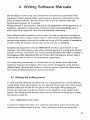
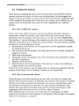
4.1 Phasing the writing process
47
4.1.1 Adjustment to the reader. . . . . . . . . . . . . . . . . . . . . . . . . .. 47
4.1.2 A writing process model
" 49
Vll
Contents
4.2 Writing the manual
4.2.1 How to define the contents
4.2.2 How to structure the manual
4.2.3 Choice of words . . . . . . . . . . . .
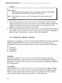
4.3 Criteria for effective manuals . . . . . . . . .
4.4 The SIMPLEXYS reference manual
4.4.1 The Objective
4.4.2 The Structure . . . . . . . . . . . . . .
4.4.3 Test results
. . . . . . . . . . . . . . . . . . . .. 52
52
52
. . . . . . . . . . . . . . . . . . . .. 53
. . . . . . . . . . . . . . . . . . . .. 54
56
56
. . . . . . . . . . . . . . . . . . . .. 56
56
Conclusions
59
References
61
Appendix A, Contents of the SIMPLEXYS reference
63
viii
1 Introduction
The first computers were developed in the mid-1940's and perceived as very large and
fast calculating machines. They were ideal for making tedious but simple calculations.
The computer became even more useful as storage capacity expanded and the computer
was capable of much more. Von Neumann, Turing and many other pioneers opened the
door for fast development in computer science. This led to the development of Artificial
Intelligence. Artificial Intelligence (AI) aims to let machines do what earlier required
human intelligence. The main objective of AI is to develop computer programs that are
capable of 'human reasoning' or 'thinking'.
A special field within AI is the design of real time rule based expert systems. Most
existing expert systems cannot manage real time processes, because it takes too much
time for them to look up (e.g., in their complex LISP-program-structures) the knowledge
they need.
At the division of Medical Electrical Engineering of the Eindhoven University of
Technology, a real time Expert System Toolbox called SIMPLEXYS has been developed
during the last seven years [Blom,1990]. SIMPLEXYS was mainly designed for
monitoring tasks in medical applications, where efficiency and performance are of
primary concern. At this moment an expert system for intelligent alarming for an
anesthesia machine and a blood-pressure controller are examples of successfully
developed SIMPLEXYS applications.
The SIMPLEXYS toolbox contains a rule compiler, a semantic and protocol checker
and a debugger/tracer. After completing the toolbox, the need arose to develop a user
interface, including a user manual and reference manual.
The main objective of the SIMPLEXYS user interface is to resemble other well known
interfaces such as Turbo Pascal, so that inexperienced users can easily develop SIMPLEXYS real time expert systems. Therefore Turbo Pascal's Turbo Vision toolbox was
used to develop the interface.
In this report I shall discuss the features of the SIMPLEXYS toolbox and the step-bystep development of the SIMPLEXYS user interface, including a brief discussion about
Turbo Vision and object-oriented programming.
In section 4 the outcome of an examination of how to write good manuals will be
described. The report is ended with some remarks and conclusions.
Besides this report two manuals were written, to give the user a hand when he/she starts
to develop SIMPLEXYS expert systems. The user manual is a thorough treatment of the
use of SIMPLEXYS and its interface. The reference manual should be used when one
needs quick help on a subject.
9
2 SIMPLEXYS
An Expert System Toolbox
The SIMPLEXYS user interface is meant to be a tool for experienced and inexperienced
programmers who develop real time expert systems. Therefore real time expert systems
and the toolbox SIMPLEXYS are introduced in this section. The material presented in
this section is intended to serve as a review. For thorough treatment of the subject, see
[Blom,1990].
2.1 Introduction to SIMPLEXYS
Real time expert systems must be fast. Beside this, real time expert systems must be
safe. A set of tools has been designed that geared to both [Blom,1990]. The set of tools
provides speed, because a 'semantic network' has been chosen as the internal knowledge
representation technique (a semantic network can be used in a way that avoids
searching). It provides safety because several checks of the consistency of the stored
knowledge is possible, where many other expert system tools don't offer such checks.
The name of the developed set of tools is SIMPLEXYS, a contraction of 'simple' and
'expert systems'. SIMPLEXYS enables the creation of real time rule-based expert
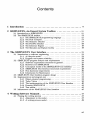
systems. In figure 2.1 a general system configuration is represented. The expert system
evaluates input data and intermediate results using the knowledge that is implemented.
After evaluation, it can derive some conlusions. The real configuration is dependent on
the application. An example is given in figure 2.2. This figure represents an expert
system in an operating room. The inputs consist of data (which can be validated and
preprocessed) from the patient monitors. The conclusions that can be drawn from the
input data, can directly indicate an alarm situation or can indirectly be used to control
some processes such as regulation of the blood pressure.
SIMPLEXYS Expert Systems have some features that are not present in many other
expert systems. These features are:
1. Both static and dynamic environments can be handled efficiently by SIMPLEXYS,
where most other expert systems can only handle static environments. In contrast
with dynamic environments, static environments can only process time-invariant
information. SIMPLEXYS handles a dynamic environment by regarding it as a
sequence of static environments.
11
2 SIMPLEXYS, An Expert System Toolbox
intermediate
results
input data
simplexys
user
process control
Figure 2.1 General system configuration
patient monitoring
1
2
N
doctor
Expert
patient
infusion
KJ-------------l
pump
Figure 2.2 Application configuration
12
System
2 SIMPLEXYS, An Expert System Toolbox
2.
The efficiency of SIMPLEXYS is due to several factors; the most important one is:
in each run rules are evaluated only once and only in those contexts in which they
are relevant, thus preventing a combinatorial explosion of the search space.
3.
In SIMPLEXYS, all rules remember their past: the history of a rules' value can be
used in inferencing.
4. To be as safe as possible, SIMPLEXYS has besides a rule compiler (which
performs checks for syntactic errors like typing mistakes) also a tool to check for
several semantic errors in the acquired knowledge base. We think that the logic of
many knowledge bases can be practically error-free, because many errors can be
detected.
2.2 The SIMPLEXYS toolbox
To obtain a working expert system, the created knowledge base has to be linked with
the inference engine. Conversion from knowledge base to expert system is done by the
SIMPLEXYS toolbox. The SIMPLEXYS toolbox consists of the following components:
1. The SIMPLEXYS language, especially designed to describe human knowledge. A
program written in this language is called 'a knowledge base' or 'a knowledge
program'. Such a program is the formal description of the domain knowledge
available in the expert system and is easy to understand for a non-expert
programmer, because of the simplicity of the language.
The language is a superset of Pascal, and has an intuitive interface to Pascal
procedures, e.g., to perform data aquisition or to display the results.
2. The SIMPLEXYS Rule Compiler, that compiles the knowledge base into an internal
representation that can be handled by the inference engine.
3. Several checkers that perform semantic and protocol checks on the knowledge base
in addition to the Rule Compiler. These checkers are called the Semantic Checker
and the PetriNet Checker (i.e., Protocol Checker).
4.
A program, called the Options Builder, that asks for a number of debugging options
that can be incorporated into the expert system.
5. The SIMPLEXYS Inference Engine, that performs the expert system's reasoning
mechanism. When the inference engine is linked with the internal representation of
the knowledge a ready to run SIMPLEXYS Expert System results.
13
2 SIMPLEXYS. An Expert System Toolbox
6.
An Explain facility to show the links between rules.
7.
A Simulate facility to examine the expert system's results after the run, from data
stored on disk by the expert system.
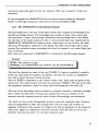
The components of SIMPLEXYS are visualized in figure 2.3 and are briefly described
in the next subsections. A description of the files generated by the Rule Compiler can
be found in section 2.2.2.
KNOWLEDGE BASE
Rule Compiler
files generated
I\lses.qqq
rinfo.qqq
rteslqqq
I---+--- rdodo.qqq
rinex.qqq
rhist.qqq
Semantic Checker
PetriNet Checker
Options Builder
options.qqq
Inference Engine
all .qqq files
included
~
Explain
I
EXPERT SYSTEM
~
<O-j_S_i_m--.U_la_te_
Stored results _ _-----'If
Figure 2.3 The SIMPLEXYS toolbox
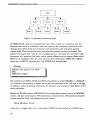
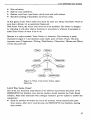
The purpose of the expert system (Le., the inferencing process) is to derive all necessary
conclusions (or goals) about data that are offered to the system. Deriving conclusions is
equal to evaluating goal rules. For the evaluation of a goal rule it is often necessary to
evaluate other (goal) rules. This is visualized in figure 2.4. The goal rule 'Rule l'
depends on the evaluation of'Rule 2', 'Rule 3' and 'Rule 4'. The inferencing process
wants to evaluate 'Rule l' and therefore it first has to derive conclusions about 'Rule 2',
'Rule 3' and 'Rule 41 (that are also dependent on other rules!). The evaluation of its goal
rules is called one 'run' of the expert system. One run is handled fast enough by
SIMPLEXYS expert systems to be real time.
If the expert system has derived its conclusions during one run, another run may be
necessary, because the data offered to the system has changed. The expert system has to
14
2 STMPLEXYS, An Expert System Toolbox
evaluate its goal rules again for this new situation. This way a sequence of runs can
take place.
In next paragraphs the SIMPLEXYS tools to build an expert system are discussed
briefly. A thorough description of the tool can be found in [Blom,1990].
2.2.1 The SIMPLEXYS programming language
The knowledge base is the part of the expert system that contains the knowledge of its
specific knowledge domain. The knowledge base consists of many rules, where each
rule represents a 'chunk' of knowledge. (Sometimes the knowledge base is also called
the rule base of the expert system). A rule is a three-valued logic type implemented in
SIMPLEXYS; SIMPLEXYS is based on three-valued logic. A rule can have the value
TR (true), PO (possible, unknown) or FA (false). The three-valued logic type is used,
because this resembles human reasoning better than for example a two-valued logic type
such as boolean.
How rules are constructed in SIMPLEXYS is illustrated in the following example:
Example
TIGER: The animal is a tiger'
MAMMAL and CARNIVORE and TAWNY and BLACKSTRIPED
The first line denotes the name of the rule (TIGER). To improve readability, symbolic
names are used instead of numbers. In addition, the first line contains an explanation
line, that is placed between inverted commas.
The rule TIGER is dependent on the values of other rules. These rules are given in the
second line. The expert system will draw the conclusion 'TIGER is TR' only if the other
four properties (mammal, carnivore, tawny and blackstriped) have the value TR.
The rules of the knowledge base are linked in a semantic network; a collection of nodes
(here: rules) and links (here: relations, that specify how rules are related). So the
semantic network represents how the rules (chunks of knowledge) are interrelated.
Two kinds of rules can be distinguished: primitive rules and evaluation rules. Primitive
rules are independent of other rules and get their value by some sort of direct assignment. Evaluation rules operate on a higher level and are dependent on the values of
other rules. Figure 2.4 represents a semantic network, where the rules 5 to 9 are the
primitive rules and the rules 1 to 4 are the evaluation rules.
15
2 SIMPLEXYS, An Expert System Toolbox
Rule 1
,--i--+
Figure 2.4 Semantic Network of rules
In SIMPLEXYS, rules are evaluated only once. This is done in a recursive way. To
determine the value of evaluation rules, the values of the constituent rules have to be
obtained first. When these are evaluation rules themselves, the evaluation process
repeats itself. This recursive process ends when the primitive rules are reached. The
primitive rules get their value by direct assignment (Le., the result of a test (Test rule),
the answer of a question (Ask rule), earlier results (Memo rule) or context (State rule».
Below is an example of the use of an Ask rule. The combination THEN FA: CIllLD
states that if ADULT becomes true, rule CHILD will become false.
Example
ADULT: 'The person is an adult'
ASK
THEN FA: CHILD
The collection of THEN, ELSE and IFPO (if possible) is called THELSEs. A THELSE
is a construct that specifies a certain action must be performed if the rule that it belongs
to obtains a certain matching conclusion; the action is a by-product or 'side effect' of the
rule's evaluation.
Beside the RULES section, SIMPLEXYS knowledge bases consist also of a PROCESS
section. AIl state transitions or ON-statements are inserted here. ON-statements describe
context switches. Each ON-statement has the format:
ON tg FROM sl TO s2
where tg is a trigger rule, s1 is a non-empty STATE rule list and s2 is a STATE rule
16
2 SlMPLEXYS. An Expert System Toolbox
list. A state switch or context switch takes place if all rules in list s1 have conclusion
TR and if the trigger rule evaluates to TR. On a change of states all STATEs in s1
become FA and all STATEs in s2 become TR.
The logic used in SIMPLEXYS is very much like boolean logic. Boolean logic is very
fast and easy to use, which makes it suitable for real-time applications. SIMPLEXYS
expressions consist of two entities, propositions and operators. Propositions are
indicated by names, such as a, b, c, pressure, normal etc. Operators are either monadic
(these operators have just one argument, e.g., not b) or dyadic (these operators have two
arguments, e.g., b and c).
2.2.2 The Rule Compiler
The Simplexys Rule Compiler translates the knowledge base into an internal representation of six qqq-files:
• rinfo.qqq:
Contains all the arrays and tables used for representing the rules and
their mutual connectivity.
Contains all the test sections defined in the test rules.
rtest.qqq:
Contains the information about the history sections.
rhist.qqq:
rdodo.qqq: Contains the collection of DO sections used in the knowledge base.
Contains the initialization sections and exit sections.
rinex.qqq:
Contains the Turbo Pascal units used by the knowledge base.
ruses.qqq:
•
•
•
•
•
Besides this, the Rule Compiler also checks the knowledge base for some semantic and
syntactic errors and gives an appropriate error message to the programmer. Examples of
errors that can be detected in this stage are 'THEN, ELSE or IFPO expected', 'rule store
overflow' and 'duplicate rule name'.
These checks are, although very simple, quite useful. Many common errors in the
knowledge base are detected by the Rule Compiler.
Another very useful feature of the Rule Compiler allows stepwise development of the
knowledge base. If the SIMPLEXYS Rule Compiler finds that rules are missing, it can
automatically generate those missing rules as Ask rules. Thus knowledge implementation can proceed in an orderly, top-down manner.
2.2.3 The Semantic Checker
The SIMPLEXYS Semantic Checker performs several semantic checks on the file
rinfo.qqq (generated by the Rule Compiler) and generates error messages if any errors
are detected. Semantic Checking is a powerful tool for (partially) proving rule base
correctness.
17
2 SIMPLEXYS, An Expert System Toolbox
Two examples of semantic errors that can be checked by this program are:
• Self referencing evaluation loops: Whenever a rule is part of its own evaluation
expression, evaluation is never-ending. For example,
Rl: PI and P2 and P3 and Rl;
• Conflicting thelses: An error occurs when a rule is tried to set to TR and FA at the
same time. For example,
Rl: then TR R2; Rl: then FA R2;
The Semantic Checker runs without user interaction. It acts as an extra pass of the Rule
Compiler. Running the checker is not strictly necessary and may be skipped if the
knowledge base IS rule structure remained unmodified.
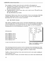
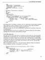
2.2.4 The PetriNet Checker
This checker is designed to detect errors in the process description part or the protocol
of the knowledge base. The ON-statements (see 2.2.1) in the knowledge base define the
protocol. The protocols are translated into Petri nets. Figure 2.5 shows the graphical
representation of a set of ON-statements as a protocol.
ON-statements:
ON tl
ON t2
ON t3
ON t4
ON t5
ON t6
FROM sl
FROM s3
FROM s3
FROM s4
FROM s2
FROM s6
TO s2
TO s5
TO s4
TO s5
s5 TO s6
TO *
sl and s3 are State rules with initial values true.
Figure 2.5 Graphical representation of ON-statements.
The relationship between the protocol and the remainder of the knowledge base is that
the protocol defines the goals that must be evaluated. The other sections of the knowledge base deliver the values of the triggers, needed for a context switch.
PetriNet or Protocol checking is done quite extensively and covers syntax, topology as
well as dynamic errors.
Just like the Semantic Checker, the PetriNet Checker runs without user interaction and
18
2 SIMPLEXYS. An Expert System Toolbox
acts as an extra pass of the Rule Compiler. Just as it is not strictly necessary to run the
Semantic Checker if the knowledge base's rule structure has remained unmodified, it is
not necessary to run the PetriNet Checker then either.
2.2.5 The Inference Engine
The SIMPLEXYS Inference Engine builds the expert system by compiling the several
qqq-files and inference processes into one 'program'. The Pascal compiler checks for
any errors in a knowledge program's Pascal code sections. If no errors occur, the expert
system is now ready to run. This expert system is able to 'reason' by itself, using the
knowledge of its specific knowledge domain.
The purpose of the inferencing process is to derive all possible conclusions about data
that are offered to the system; all goal rules must be evaluated.
The SIMPLEXYS Expert System starts with evaluating the Thelses of all State rules
with value TR. This way the initial goals will be reached. At the end of the run, when
all the goals are evaluated, the ON-statements are executed, possibly resulting in context
changes. As long as at least one State rule has value TR, a new run is started, otherwise
the system halts.
2.2.6 The Simulate and Explain facility
Experts and knowledge engineers will not trust an existing expert system by just
looking at the final decisions it takes. They want to know how the expert system came
to these decisions. Therefore some debugging tools have been developed [Philippens,1990]. These debugging tools consist of a simulator, which makes it possible to
'trace' through the whole inferencing process, and an explain facility for examination of
the evaluation structure of the process. With the help of these tools, the knowledge
bases can be checked and debugged or correctness and efficiency can be proved to
experts in the domain problem-field.
19
3 The SIMPLEXYS User Interface
In this section the step-by-step development of the SIMPLEXYS User Interface will be
discussed. To come to a safe and structural design, which is also in accordance with the
user requirements, I used software engineering techniques. Therefore I will first
introduce some aspects of software engineering.
3.1 Introduction to software engineering
In the development of large programs, often many problems arise. The program has to
be safe and reliable, must answer the requirements and be of acceptable quality. The
term software engineering covers all activities to meet these problems [Sommerville,1988]. Software engineering is mainly based on software programming techniques,
although it is also influenced by mathematics, psychology, ergonomics and management
knowledge. The software engineer has to be capable of applying present computer
techniques in an efficient way. As the electrical or mechanical engineer applies physics
and mathematics, the software engineer applies software techniques, obtained by more
fundamental research.
In the late 1960's the problems in making large programs became clear and since then
great progress has been made. Higher programming languages have pushed aside
machine language; structural programming is applied on a large scale and this includes
that programs are more readable, reliable and portable. In spite of some major breakthroughs, still many software products are developed, that are unreliable, poorly
documented and not in accordance with the user requirements. Thus effective software
engineering is of great importance.
3.1.1 A Iifecycle model
The development of large programs and extensive software products costs a great
amount of time. Generally these programs or systems will be used even longer. The
process of development and usage of a system can be divided into five steps. These
steps are called the lifecycle model of the program or system.
A first lifecycle model was proposed by Royce (in 1970) and then several other models,
with all kinds of small changes, followed.
21
3 The SIMPLEXYS User Interface
All these models can be covered by one lifecycle macro model [Sommerville,1988]:
1
Problem analysis and requirements. In consultation with the users of the system,
its performance (i.e., what must the system be able to achieve), its restrictions and
its goals are established. Mier the consultation between user and developer, the
agreement is usually described in some informal way that is comprehensible for
both.
2. System and program design. A system is a combination of hardware and software. It
is also the software engineer's duty to find the right combination according to the
earlier established performances and requirements of the system. The examination
of the right combination is called system design. Program design is the research of
the possibilities to transform the system requirements into specifications for (one or
more) computer programs.
3. Implementation and program test. During this step the program specifications (Le.,
program design) will be coded into one or more programs or subprograms,
described in a suitable language. These programs are tested separately; do they
match the requirements?
4. System test. If the system consists of more than one program or subprogram, these
programs are linked together and the total system will be tested. The system can
only be used if it answers the requirements. System tests are also called a-tests.
5. Maintenance. This is the final step of the Iifecycle model. Usually this step also
takes most of the time of the Iifecycle. The system or program will be installed and
is ready for use. Maintenance implies correction of bugs not found earlier (during so
called B-tests, testing by using), improvement of the system's performance and
adjustment of the system to possible new requirements.
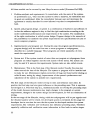
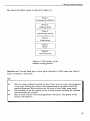
The first steps of the lifecycle model overlap in time and influence each other. In
practice the final step can have great influence on the preceding ones. This is represented in figure 3.1. This final step (Le., maintenance) does not overlap the preceding steps
of the model, because maintenance may imply changes in the program or system
requirements, changes in the system design and development, as well as continuation of
testing.
In the test stage of the lifecycle, during which the subprograms will be put together and
the obtained system will be tested, the developed system is validated. In this stage the
developer has to convince the user that the system he developed matches the system
requirements. But validation and verification also influence preceding steps. Therefore
especially validation and verification cause information to flow back to earlier stages.
22
3 The SIMPLEXYS User Interface
Though they seem synonymous, it is better to make a distinction between validation and
verification. Boehm makes this distinction as follows:
Verification: 'Does the system match the requirements?'
Validation: 'Does the system match the user's desires?'
requirements
system
design
.---.L...-_L..--_--,
implementation .----'----'-_---,
tests
- - program and system development - - -
Figure 3.1 Lifecycle model of systems and programs
The desires of the user must be defined at the beginning of system development.
However, these desires can change in the course of time. This was a reason for
McCracken, Jackson and Gladden to propose a replacement of the Iifecycle model by a
more evolutionary model for the development of programs or systems. This model was
based on the idea that a 'prototype' should be introduced to the user as soon as possible.
This prototype must then be developed in such a way that quick modifications are easy
to make. The prototype will be changed, until the user is satisfied.
It is true that a more evolutionary approach of developing systems can lead to better
results, especially when the system is a totally new idea, and when it is hard for the
user express his desires in advance.
Boehm thinks that the 'prototype' model is difficult to use when very large systems are
to be developed. The best method or model for the development of large systems or
programs cannot be given, but possibly it is a combination of the Iifecycle model and
the evolutionary model.
3.1.2 Program and system reliability
With the increasing variety of computer applications, it becomes more and more
obvious that reliability is the most important property of programs and systems. The
reliability of these programs and systems depends on the correctness of the program or
23
3 The SIMPLEXYS User Interface
system design, the correctness of the development and the reliability of other components in the systems (e.g., other hardware or software components).
It is difficult to give a definition of reliability of programs or systems. Some will say
that correctness includes reliability, that the program should match the specifications
and that it should be efficient. This is a possible definition, but even specifications can
be incomplete and incorrect.
A more realistic definition of a reliable program is:
• a program (or system) that matches the program specifications;
• a program that never gives incorrect output, no matter what the inputs are;
• a program that never destroys itself;
• a program that does meaningful things in unexpected situations;
• a program that halts only if further progress is really impossible.
The development of programs with a high grade of reliability inevitably costs a lot
extra. It implies the execution of many check procedures, the execution speed drops and
the code size increases. Experienced software engineers, however, still go for reliability
rather than efficiency.
3.2 SIMPLEXYS program analysis and requirements
Software engineers often have to solve very complex problems. The nature of the
problem is sometimes hard to comprehend, especially if it concerns the development of
a whole new system or program, and no model of the system or program is available.
The goals and the restrictions of the system or program then have to be determined.
This is called program analysis and definition of requirements. All the results are
recorded in the 'software requirements document'. This is usually the first stage in the
lifecycle of a program or system.
It is important to distinguish between users' desires and requirements. An organization
can decide to develop a new administration system, but it is not realistic to contact a
software engineer just with this simple need. Instead of expressing this desire, the
organization should, in consultation with the software engineer, establish the administration system's requirements. Information about the problem should be gathered and
analyzed, after which a problem definition can be drafted. Only then a program solution
can be designed and developed.
It is also important to distinguish between the goals and the requirements of the system
or program. The system has to match the requirements, where the goals only describe a
more general nature of the system. For example, 'user friendly' can be a goal of the
system. A requirement, however, can be that commands should be selected by a menu
on the screen.
24
3 The SIMPLEXYS User Interface
3.2.1 Software requirements document in general
The description of the system or program requirements is called the software requirements document [Sommerville,1988]. This document describes what the system should
do. The document tells the reader nothing about how that can be achieved. Heninger
states that a software requirements document has to meet six conditions:
1. It gives a description of the behaviour of the system in its environment.
2. It has to contain the restrictions with regards to the development.
3. It should be easy to make changes.
4. It should serve as a reference book with regard to maintenance of the system.
5. It has to contain an opinion ab~ut the Iifecycle of the system.
6. It describes acceptable reactions following unwanted or unexpected events.
So according to Heninger the software requirements document has a reference function.
This can help to maintain the system in a later stage. The information in the document
should be accurate and also easy to comprehend. When we keep this in mind, a
software requirements document can possibly contain the following sections:
1. Hardware description. If the system or program needs special hardware
configurations, this has to be described as accurately as possible. If just general
hardware is needed, the minimal and optimal configurations should be given.
2. Conceptual model. A conceptual model contains a global idea of the system and the
most important features. Usually the conceptual model is presented in a
graphical way, by a 'data flow diagram'.
3. Functional requirements. The functional requirements of the system, i.e., the
interactions with the user are described in this part of the document.
4. Data bank requirements. Data bank requirements imply the description of the
logical organization of the data needed by the system.
5. Non-functional requirements. The restrictions under which the system has to
operate, in relation to the functional requirements, are described in this part
of the document.
6. Information for maintenance. Before the system will be developed, some assumptions (e.g., hardware or software assumptions) are made. These are described in the
part 'Information for maintenance'. The expected modifications of the system or
system performance when the environment changes are also described.
25
3 The SIMPLEXYS User Interface
Before the development of the SIMPLEXYS User Interface was started, the wishes and
needs of possible users were examined. Then some of the different kinds of requirements mentioned above were researched with regard to the user interface. The results
are discussed in the following subsections. Not all the described sections of the software
requirements document are relevant for the SIMPLEXYS User Interface.
3.2.2 Hardware for SIMPLEXYS
In the past no special hardware was required to run a SIMPLEXYS real time expert
system. Running on PC-XT the expert system evaluates its goal rules during one run
fast enough to be real time. Therefore the following hardware requirements were
determined:
Because it was assumed that the intended users of the user interface will have the
disposal of at least a PC-286 with 1024 kByte RAM, this was the minimal required
hardware configuration of the Personal Computer that will run the SIMPLEXYS User
Interface.
3.2.3 Conceptual model of the SIMPLEXYS User Interface
In this section of the software requirements document, the conceptual model of the
program is described, based on the requirements of the user. The conceptual model
consists of a global description of the system, the important services the program has to
deliver and the connection between the system description and the functional interactions with the user.
When a conceptual model has been developed, a framework for a more detailed
description of the software requirements has been formed. The developer of the, though,
must not suggest that 'his' conceptual model represents the system design. Of course,
many times the model and the design will look alike.
The conceptual model usually is graphically presented (like a data-flow diagram).
The conceptual model of the SIMPLEXYS User Interface is illustrated in figure 3.2.
The most important interactions with the users and the services to be provided by the
interface are illustrated in this model.
The next step in this phase is the development of conceptual models for all the
important user-facilities. Then, if necessary, these models can also be split up into other
conceptual models. Not all the conceptual models will be presented here. As an
example, figure 3.3 and figure 3.4 present the conceptual models for File Handling and
Open Rule File.
26
3 The SIMPLEXYS User Interface
Figure 3.2 Conceptual model for SIMPLEXYS User
Interface
open
rule file
open
new file
input
text
save I
save as
give
file name
read
file
input text
put file
on screen
directory
directory
Figure 3.3 Conceptual model for File
Handling
Figure 3.4 Conceptual model for
Open Rule File
27
3 The SIMPLEXYS User Interface
3.2.4 SIMPLEXYS User Interface functional requirements
The user expects some services, provided by the system that has to be developed. These
expected services are called the functional requirements of the system. Generally users
are not interested in how these services are provided. Therefore the software engineer
must take care not to be tempted to describe how he thinks these services can be
offered.
The requirements have to be both complete and consistent. Complete implies that it
should mention all expected services or requirements. Consistent means that no two
requirements are contradictory. The functional requirements usually grow during the
program development process. Unsolved problems during later stages or changes in the
market can be motives to change the functional requirements.
There are three ways to formulate the functional requirements:
• In a natural language.
• In a structured language with certain rules, but without exact syntax or semantics.
• In a formal specification language with its own syntax en semantics.
Generally a natural language is used to describe the requirements. Both programmer and
user are able to understand text written in this language. Besides that, the programmer
and user can express themselves better using a natural language.
Sometimes a structural language is used to describe functional requirements.
The use of a fonnal specification language is still under investigation, but is used more
and more.
An example of a requirement described in a formal specification language is illustrated
below. The meaning of the description is that a new window can only be opened if
there is no other activity. Mter the new window is opened, this will also be the active
window.
Example
'Open New Window':
{Pre: No Activity = True;}
{Post: Active_Window = New_Window;}
In the next example it's made clear why a formal specification language is not always
easy to understand. The example says that the Rule Compiler can be activated only if
there is no other activity and a rule base is in the active window. Mter the rule base has
been compiled, the active window still contains the rule base. If an error occurred then
28
3 The STMPLEXYS User Interface
the cursor will be moved one line above the line that contains the error and an error
message is printed.
Example
Rule Compiler:
{pre: (No_Activity True) and
(Active_Window = File_Window);}
=
{post: (Active_Window = File_Window) and
[ (ErrorList <> NULL and ErrorLine = Y
and CursorPos = (O,y) and Print(ErrorMessage) )
or ErrorList = NULL ]; }
The functional requirements for the SIMPLEXYS User Interface were presented to me
in a natural language. The requirements looked very vague, but one was not interested
in how the user interface would match these requirements. Of course a more detailed
description of the requirements was necessary. Not all of the requirements will be
discussed thoroughly. Only a few more detailed functional requirements are presented
here.
The original functional requirements that were given to me:
1. Rule bases must be accessible in the SIMPLEXYS User Interface.
2. Rule bases must be compiled and if there occur any errors, error messages must be
shown.
3.
4.
5.
6.
Rule bases must be checked by the two checkers. If any error occurs, an error
message must be shown.
The user must be able to set the SIMPLEXYS expert system's options.
The Inference Engine and the knowledge base must be linked.
The SIMPLEXYS User Interface must have an (on-line) help function.
Functional requirement no.1: 'Rule bases must be accessible in the SIMPLEXYS User
Interface' can be divided into several more detailed requirements:
1.
1.1
1.2
1.3
Rule bases must be accessible in the SIMPLEXYS User Interface.
The user must be able to find a rule base.
The user must have the option to open a rule base file.
After opening a rule base file, the user must be able to make changes in this file
(Le., edit the file).
1.3.1 Several edit functions like selecting text, deleting text, copying text, pasting
selected text, must be available.
29
3 The SIMPLEXYS User Interface
1.3.2 To make these edit functions useful, a clipboard (see [Borland,1990]) must be
present.
1.4 The user must be able to save new or changed rule bases.
A more detailed description of the second functional requirement is:
2.
Rule bases must be compiled and if any errors occur, error messages must be
printed.
2.1 The user must be able to compile a rule base.
2.2 After compiling, the edit window with the rule base file in it should be active
again.
2.3 If an error occurs, the cursor should move to the erroneous line and the
error message should be printed.
2.4 If no error occurs the statistics of the rule compiler must be printed.
2.4.1 The statistics must be printed in a window with scroll bars.
2.4.2 The user must be able to 'tell' the user interface when he finished reading the
statis tics.
In this way all SIMPLEXYS User Interface functional requirements were described in
more detail.
3.2.5 Non-functional requirements
Non-functional requirements contain restrictions with regard to the system. Examples of
non-functional requirements are: rules for the representation of system output (e.g., data
or messages) and the restrictions on memory use.
Non-functional requirements tend to be in contradiction with, or have interaction with,
the functional requirements. To choose between execution speed and memory use is an
example of a possible contradiction.
The non-functional requirements for the SIMPLEXYS User Interface are:
1. The SIMPLEXYS User Interface is meant for experienced as well as non-expert
programmers.
2. The interface must user-friendly. The user must be able to find his way through the
program.
3. The SIMPLEXYS User Interface must resemble the Turbo Pascal interface.
4. Ail messages printed by the user interface must be in English.
5. Future programmers must be able to add new functions to the interface easily.
30
3 The SIMPLEXYS User Interface
3.2.6 Information for Maintenance
This section of the software requirements document contains information about the
assumptions that are made, before the program or system is developed. Possible changes
in the future and the consequences are described. If possible the functions that could
change in the near future must be given.
Information for maintenance for the SIMPLEXYS User Interface is:
• With object programming coming into fashion it is not unlikely that some tools of
the SIMPLEXYS toolbox will be rewritten using object oriented design methods (all
tools are written in top-down manner). According to De Vries [Vries,1993] this can
increase the quality of SIMPLEXYS.
The User Interface is developed such, that the executables of the rewritten tools can
replace the current ones in the source code.
• Also Windows programming is becoming a fashion. A Windows version of
SIMPLEXYS can become desirable. Although the construction of the User
Interface's source code (using Turbo Vision) looks very much like the source code
of the Windows version of SIMPLEXYS would look like, it will cost some effort to
write the Windows version for SIMPLEXYS.
When a Windows version has been developed, it is still advisable to maintain the
developed Dos version.
3.3 SIMPLEXYS User Interface program design
A good design and development of a program are the keys to effective software
engineering. If a program is well designed it can be straightforwardly implemented,
introduced and maintained. The program is then easy to understand and to use and it is
reliable. Badly designed programs are hard to maintain, hard to test (for example on
consistency) and unreliable, although these programs may work in the beginning.
Program design is therefore the most critical and important phase in the software
engineering.
Until recently, the development of software was an ad hoc process. Based on the
established requirements an informal design was made. But during the coding phase this
design was regularly adjusted, what generally made the implemented program not to
match all requirements anymore.
Nowadays we know that informal designs of a program are not sufficient as a tool for
coding the program. The design must be made more formal and more strict, than
programmers were used to. Many design tools (such as HIPO schemes, data flow
diagrams and structure diagrams, [Sommerville,1988]) are developed for this reason.
31
3 The SIMPLEXYS User Interface
Structure diagrams are used to represent the SIMPLEXYS User Interface design. These
diagrams illustrate the hierarchical structure of the system components. The main
structure of SIMPLEXYS is illustrated in figure 3.5. Only the main procedures/functions
are represented. Of course, the final design of SIMPLEXYS was far more detailed and
more complex, and contains all functions and procedures that may be implemented. In
this paragraph only the method of designing is discussed, and this is best illustrated by
figure 3.5.
Figure 3.5 Main structure diagram of SIMPLEXYS
After the design process, the developed structure diagram of SIMPLEX User Interface
gave a very good idea of how the interface would look. The components of the system
were clearly visualized and this would be a great help implementing the interface.
32
3 The SIMPLEXYS User Interface
3.4 Implementation and program test
Borland's Turbo Vision is used to implement the SIMPLEXYS User Interface. Turbo
Vision is a result of the use of object-oriented programming techniques. All the
developed object classes can be successfully used by any other programmer. Of course,
the use of Turbo Vision implies object-oriented programming.
In this paragraph both Turbo Vision and the Object-Oriented Programming (OOP)
techniques will be discussed. After this introduction of the used programming techniques the implementation and the test results of the SIMPLEXYS User Interface will be
discussed.
3.4.1 Object-oriented programming
Though object-oriented programming has become a very fashionable notion, the techniques are not as revolutionary as most people think they are [Vries,1993]. Experienced
programmers of well structured software probably will not even make too much
progress when they start to program object-oriented instead of using 'their' procedural
language (e.g., Pascal).
Of course, using object-oriented programming still has some advantages. The most
important one is that the developed software will be more structured, extensible and
easy to maintain.
Three main properties characterize an object-oriented programming language [Borland,1990]:
• Encapsulation. Combining a record with the procedures and functions that manipulate it to form a new data type... an object.
• Inheritance. Defining an object and then using it to build a hierarchy of descendent
objects, with each descendant inheriting access to all its ancestors' code and data.
• Polymorphism. Giving an action one name that is shared up and down an object
hierarchy, with each object in the hierarchy implementing the action differently,
appropriate for its use.
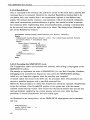
3.4.1.1 Inheritance
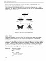
The classification process called taxonomy is a good starting metaphor for the inheritance mechanism of object-oriented programming.
Within the animal family of insects there are many different classes. Each class has its
own set of behaviors and characteristics that define it. Each class can be presented in
the insect-family-tree. The highest level in this tree is most general one and each level
is more specific than the one before it (see figure 3.6). Once a characteristic is defined,
all objects beneath that definition include that characteristic.
33
3 The SIMPLEXYS User Interface
Object-oriented programming is the process of building the family-tree for data
structures: the hierarchy of object classes.
This process by which one type inherits the characteristics of another type is called
inheritance. The inheritor is called a descendant type; the type that the descendant type
inherits from an ancestor type.
..
'
Winged
r'-Butterflies
Figure 3.6 Part of the insects family-tree
3.4.1.2 Objects
Objects and records are very much alike. The fields of objects cannot only contain
variables (as in records), but can also contain methods (functions or procedures)
declarations.
The new data type object was added to the Pascal language by Turbo Pascal to support
inheritance. An object type can function as a complete, stand-alone type in the fashion
of Pascal records, or it can be defined as a descendant of an existing object type by
placing the name of the ancestor type in parentheses after the reserved word object.
The example below should give an idea of how to use objects.
Instead of:
Location = record
X, Y: Integer;
end;
Point = record
position: Location;
Visible: Boolean;
end;
34
3 The SIMPLEXYS User Interface
Use objects:
type
Location = object
X, Y: Integer;
end;
Point = object (Location)
Visible: Boolean;
end;
Including methods:
type
Location = object
X, Y: Integer;
procedure Init(NewX, NewY: Integer);
end;
procedure Location.Init(NewX, NewY: Integer);
begin
X := NewX {The X field of a Location object}
Y := NewY {The Y field of a Location object}
end;
To initialize an instance of type Location, simply call its method as if the method were
a field of a record:
var
MyLocation: Location;
MyLocation.Init(18,24);
As expressed in former examples, inside an object a method is defined by the header of
the function (or procedure) that acts as a method. Method declarations within the object
tell what a method does, the how is defined outside the object.
3.4.1.3 Polymorphism
Virtual methods make it possible that methods, that have the same name within different
object classes, can be implemented differently. This is called polymorphism.
In the example below the method Show will be defined within Point as well as within a
descendant type to Point, named Circle. Both methods have the same name, but are
implemented differently. Point.Show is said to be overruled by Circle.show.
type
Point = object(Location)
Visible: Boolean;
constructor Init(InitX, InitY: Integer);
procedure Show; virtual;
end;
35
3 The SIMPLEXYS User Interface
Circle = object(Point)
Radius: Integer;
constructor Init(InitX, InitY, InitRadius: Integer);
procedure Show; virtual;
end;
procedure Point.Show;
begin
Visible := true;
SetPoint (X, Y) ;
end;
procedure circle.Show;
begin
Visible := true;
Graph.Circle(X,Y,Radius);
end;
In the examples above the term constructor is introduced. Every object that has virtual
methods must have a constructor. A constructor is a special type of procedure that does
some setup work for the machinery of virtual methods.
3.4.1.4 Advantages of OOP
The main advantages of Object-oriented programming are:
• hierarchical structure
•
•
•
polymorphism
possibility of reusing defined object classes
necessity of structural problem solving
More about Object-oriented programming and its advantages can be found in [Borland,1990].
3.4.2 Turbo Vision
Turbo Vision is an object-oriented tool of Borland (Turbo) Pascal. In this paragraph
some of its objects and the hierarchy of its objects will be discussed. It will be an
overview. More about Turbo Vision can be found in [BorIand,1992].
3.4.2.1 What is Turbo Vision
Turbo Vision is an object-oriented application framework for windowing programs.
Turbo Vision was created to save software developers from endlessly repeating the
basic platform on which they have to build their application programs.
Turbo Vision includes:
•
•
•
36
Multiple, resizeable, overlapping windows.
Pull-down menus.
Dialog boxes.
3 The SIMPLEXYS User Interface
•
•
•
•
Data validation.
Built-in color installation.
Buttons, scroll bars, input boxes, check boxes and radio buttons.
Standard handling of keystrokes and mouse clicks.
At first glance Turbo Vision looks very much the same as a library. But Turbo Vision is
more than a library, it's an application framework.
With Turbo Vision, the source code never has to be modified. The 'library' is changed
by extending it with other objects, functions or procedures or whatever is necessary to
make Turbo Vision do what it has to do.
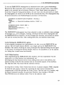
Because it is object-oriented, Turbo Vision is a hierarchy. This hierarchy is partly
illustrated in figure 3.7 and represents some object types of Turbo Vision. The most
important ones (TApplication, TDialog, TEditWindow, TStatusLine, TButton and TRect)
will be discussed later.
Figure 3.7 Part of the Turbo Vision object
hierarchy
3.4.2.2 Why Turbo Vision?
One of the non functional requirements in the software requirements document of the
SIMPLEXYS User Interface says, that the interface should resemble the Turbo Pascal
interface. After some discussion with colleague students I got two options to answer this
requirement:
• Study an interface developed by one of the students, which contained also pundown menus. After that I could develop the SIMPLEXYS User Interface, starting
from scratch.
37
3 The SIMPLEXYS User Interface
•
Use Turbo Vision, which directly implied the resemblance to Turbo Pascal. This
way I could avoid reinventing the same old wheel again.
The choice was not that hard to make.
3.4.2.3 The most important objects of Turbo Vision
In this paragraph the most important objects of Turbo Vision and their field and
methods will be discussed. In this case 'most important' means 'most used' when I
implemented the interface.
TApplication
TApplication is a simple 'wrapper' around TProgram and differs from it only in its
constructor and destructor methods. Usually, application objects will be derived from
TApplication. TApplication contains several methods for handling standard application
commands: HandleEvent method that handles commands from the standard menus, and
methods that tile and cascade windows and shell to Dos. All these defined methods can
actually be used by the software developer.
TApplication inherits a lot of object TProgram. The most useful methods inherited are
InitDesktop, InitMenuBar, InitStatusLine and InsertWindow.
InitDesktop constructs a desktop object for the application. InitMenuBar constructs a
(default empty) menubar. This method almost always should be overridden, to provide a
user-defined menubar. InitStatusLine constructs the status line, with default the string
'Alt+X Exit' being displayed. This method also needs to be overruled. InsertWindow
inserts defined windows on the desktop.
The implementation of the SIMPLEXYS User Interface is mainly based on TApplication. I extended this object with procedures and functions evolving from the structure
diagram, illustrated before. More about this extension will be said later.
TDialog
TDialog is a specialized descendant of TWindow, specially designed for modal use and
for holding controls. Dialog box objects differ from windows by default in the following
ways:
• Dialog boxes are not growable.
• Dialog boxes are closable (by default windows are not) and moveable.
• The TDialog event handler calls TWilldow.HandleEvent, but also handles the special
cases of <Esc> and <Enter> key response (cmCallcel respectively cmDefault).
• Dialog boxes have no window number.
Especially the second and third differences were reasons for me to use Dialog boxes for
printing text or options, because of the user-friendlyness.
38
3 The STMPLEXYS User Interface
Though Dialog boxes define their own constructor Init (creates a dialog box with the
given size and title), it does not define its own destructor. It uses Close and Done
inherited via TWindow, TGroup and TView.
TEditWindow
An editor window is a window specially designed to hold an editor object, either a file
editor or the clipboard. Just like TDialog, TEditWindow is a descendant of TWindow.
Editor windows change their titles to show the name of the file being edited and
automatically create scroll bars. If no file name is passed to the editor window, the file
is 'untitled'.
The editor window uses the Close method inherited from TWindow, unless the editor
file is the clipboard. In this case it calls Hide from TView to hide the clipboard.
TButton
A TButton object is a view that generates a command when pressed. TButton has a
title, that often indicates the command it will generate. The user can press a button by
pressing the highlighted letter, tabbing to button and press the spacebar or <Enter>, or
by clicking the button with the mouse.
Buttons have a three-dimensional look and they appear to move when they are pressed.
TButton is a 'terminal' object that can be inserted into any group. Its methods do not
need to be overridden.
TStatusLine
The TStatusLine object is specialized view, usually displayed at the bottom of the
screen. The status line can display available hot keys, available memory, time or
program hints for users.
The items to be displayed are set up in a linked list by the application object's InitStatusLine method. The string displayed by the status line depends on the help context of
the currently focused view.
A very useful method of the status line object is the method Hint. By default Hint
returns a null string, but Hint can be overridden in descendant status line objects. This
way a context sensitive hint string can be displayed. This string will be drawn on the
status line after a divider bar.
TRect
This object is mainly used to set the boundaries of a view (dialog box or window). Its
method Assign will then be used: procedure Assign(XA, YA,XB, YB: Integer);
The coordinates (XA,YA) form the left upper corner and (XB,YB) the right lower
corner.
39
3 The SIMPLEXYS User Interface
A far more detailed description of all the Turbo Vision objects can be found in the
reference part of [BorIand,1992].
3.4.3 The implementation of the SIMPLEXYS User Interface
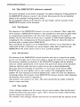
The SIMPLEXYS User Interface was implemented according to its structure diagram,
developed during the design phase. The TApplication object was extended with the
procedures/functions illustrated in this diagram. Besides this, some inherited methods
had to be overruled, and were newly defined.
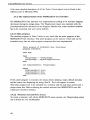
3.4.3.1 Main program
The smallest program in Turbo Vision is very much like the main program of the
SIMPLEXYS User Interface. This small program can be used as a basis and can be
extended every time an other program component has been implemented.
{Main progrdm of SIMPLEXYS User Interface}
program SIMPLEXYSi
uses APPi
type
PSimplexApp
TsirnplexApp
=
ATSirnplexAPPi
object (TApplication)
end;
var SirnplexysShell: TsirnplexAPPi
begin
SimplexysShell.Initi
sirnplexysshell.Runi
SirnplexysShell.Donei
end.
If this small program is executed, the empty default desktop, empty default menubar
and the status line displaying the string 'Alt+X Exit' will appear on screen.
This basic program has to be extended by a menubar and the pull-down menus and a
proper status line. Before defining the needed methods first SIMPLEXYS own Init
constructor should be defined.
3.4.3.2 Menubar and pull-down menus
To create a menubar with all the SIMPLEXYS menu options, the TSimplexApp object
has to define its own InitMenuBar:
40
3 The SIMPLEXYS User Interface
type
PsimplexApp = ~TsimplexApp;
TsimplexApp = object(TApplication)
constructor Init;
procedure InitMenuBar; virtual;
end;
procedure TsimplexApp.lnitMenuBar
var
R: TRect;
begin
GetExtent (R) ;
R.B.Y := R.A.Y + 1;
{The menubar is displayed at top of the screen}
MenuBar := New (PMenuBar, Init( R, NewMenu(
NewSubMenu('-F-ile', hcFile, NewMenu(
Newltem('-N-ew', ", kbNoKey, cmNew, HcFileNew,
Newltem('-O-pen...
" 'F3', kbF3, cmOpen,hcFileOpen,
nil) ) )
nil) ) ) ) ;
end;
The listing below will display a menubar with one option (File). If this option is pressed
then a pull-down menu is displayed with the two defined options (New and Open).
Option New has no hot key, whereas Open has hot key F3.
This way the menu bar with all the SIMPLEXYS options and its pull-down menus can
be implemented.
Because HandleEvent still does not recognize the commands behind the menu options,
pressing one of the options causes nothing to happen.
3.4.3.3 The status line
Not only some hot keys were meant to be displayed on the status line, but also on-line
program hints, as help for the user. To implement these hints, a descendant of TStatusLine object was defined. Within this descendant object THintStatusLine a method Hint
is defined, that ltakes care of the context sensitive hint string. An example of setting the
help context is illustrated in the listing of the menubar; after each new item the help
context ('hcl-contants) is given.
How to implement a status line is well documented in [Borland,1992], an example of
how to implement the hints, is illustrated in next listing.
function THintstatusLine.Hint(AHelpCtx: Word): string;
begin
case AHelpCtx of
hcNoContext: Hint :=
SIMPLEXYS' ;
hcFileExit: Hint := 'Exit SIMPLEXYS';
hcCompile:
Hint := 'Compile a rule base';
else Hint := , , ,
end;
end;
.
41
3 The SIMPLEXYS User Interface
3.4.3.4 HandleEvent
Once a command of the menubar, the pull-down menus or the status line is pressed, this
command has to be executed. Therefore the inherited HandleEvent method had to be
overridden and a new method had to be implemented, adjusted to the defined commands. The method mainly contains a case statement, with all the possible commands.
After each command the procedure/function is given, that should be called to execute
the command. Mter implementing these procedures/functions, pressing a command key
by the user will now cause the right action to be taken. The listing below illustrates a
part of the HandleEvent method.
procedure TSirnplexApp.HandleEvent(var Event: TEvent);
begin
inherited HandleEvent(Event) {call the inherited method first}
if Event.What = evcommand then
begin
case Event.Command of
crnNew:
NewWindow;
crnOpen:
openWindow;
crnRuc:
RulComp;
crnChk:
SemChk;
end;
ClearEvent(Event);
end;
end;
3.4.3.5 Executing the SIMPLEXYS tools
The TApplication object was extended with methods, each calling a subprogram of the
SIMPLEXYS toolbox.
The attempt to implement the tools of SIMPLEXYS (Le., the Rule Compiler, Checkers,
Debugging tools and Inference Engine) as units within the SIMPLEXYS interface,
failed on a too large data segment when the interface was compiled.
A second option was found in the DOS unit: the procedure Exec. This procedure can
execute a specified program with a specified command line.
Before the Exec procedure is called, first SwapVectors should be executed. SwapVectors
swaps the contents of the SwaplntXX pointers in the system unit with the current
contents of the interrupt vectors. This ensures that the Exec'd process does not use any
interrupt handlers installed by the current process and vice versa. Mter the Exec
procedure, of course SwapVectors has to be called again.
As illustrated in the listing below, all the SIMPLEXYS subprograms can be executed
this way.
Swapvectors;
EXec('PET41.EXE', ");
SwapVectors;
42
3 The SIMPLEXYS User Interface
To run the SIMPLEXYS subprograms as mentioned above had a great disadvantage.
Because the Exec procedure uses a command line option, the path name of the subprograms to be executed has to be known. However, Turbo Pascal knows an option to
avoid this. Using the listing printed below, the user must write the directories in which
the subprograms are saved in his PATH (in the autoexec.bat file). The subprograms may
be saved everywhere, the FindExeProgram procedure will find them.
procedure FindExeProgarn(progName: string);
begin
CrndPath := FSearch(progName,GetEnv('PATH'»;
end;
FindExePrograrn( 'PET41.EXE');
Swapvectors;
Exec(FExpand(CmdPath), . ');
Swapvectors;
The SIMPLEXYS subprograms have been adjusted in order to establish a data exchange
of messages (Le., error messages, warnings, statistics) between these subprograms and
the SIMPLEXYS User Interface. All the messages that formerly were printed on screen
will now be written into files. After reading these files, the interface erases them.
3.4.3.6 Setting the SIMPLEXYS options
A new program component was implemented to be able to set the SIMPLEXYS run
options. The developed Options Builder is no longer used in the SIMPLEXYS User
Interface. The results of calling the newly developed Run Options Dialog box are equal
to the results of running the Options Builder. However the possibility to set the options
in a dialog box is much more user-friendly.
3.4.3.7 Help function
After implementing the SIMPLEXYS User Interface, still one requirement was not
answered to: no help function was implemented yet.
Developing the help function did not mean adding much code to the software, but
implied writing a help file that contains help on all possible aspects of the interface.
The help file looks very much like the reference manual.
If a help file is written, Turbo Vision does the rest. A special compiler 1VHC compiles
the help file and creates a pascal file containing the help context constants Chc'constants) and a HLP-file specified for Turbo Vision. The final step is to compile, with
the Pascal command compiler, the generated PAS-file, thus creating a TPU-file.
This TPU-file has to be defined within 'Uses' in the software code.
43
3 The SIMPLEXYS User Interface
The help file I created contains two parts, a reference for the interface and a list of all
possible printed errors by the SIMPLEXYS tools and the error messages. From the
interface both parts can be entered independently.
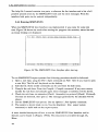
3.4.4 Running SIMPLEXYS
When the SIMPLEXYS User Interface was implemented it was ready for some test
runs. Figure 3.8 shows the result after starting the program: the menubar, status line and
an empty desktop are displayed.
file
Edit
Alt+X Exit
Compile Check
flO Menu
Options
fl Help
I
Debug Simplexys Window
SIMPLEXYS
Help
14:05:34
Figure 3.8 The SIMPLEXYS User Interface after start up
To run SIMPLEXYS expert systems first following procedure should be followed:
1. Open a rule base, using the File I Open command (or File I New if you want to open
a new file). The file will be placed on the desktop.
2. Edit the file. Some useful commands can be used from the Edit menu.
3. Compile the rule base. Press the Compile I Compile command. If any error occurs,
modify the rule base and compile again. Error messages or statistics will be shown.
4. Check the rule base on semantics (Check I Semantics) or protocol (Check I Protocol).
If errors are detected, then 'goto 2 1• The messages generated by the checkers will be
shown.
5. Set the SIMPLEXYS run options. Use the Options I Run Options command.
6. The system is almost ready to run. Use the Simplexys I Run expert system
command, to build and run the expert system.
A more detailed description of how to use the SIMPLEXYS User Interface and its
features can be found in [Poppe I, 1993b]. This document is available through IA
BIom.
44
3 The SlMPLEXYS User Interface
3.4.5 Test results
The SIMPLEXYS User Interface was, after the complete implementation, tested by
some colleague students on user friendliness, and by myself to learn some of the
interface limitations.
User friendly
According to some students, the SIMPLEXYS User Interface is easy in its use. It's clear
from the beginning what the options for the user are. The help function is extensive and
also easy to use. The possibility to switch between relevant help information, without
leaving the help function is a great advantage. Unfortunately, the help function does not
react on words edited in the edit window.
Limitations
The SIMPLEXYS User Interface has some limitations. The number of files that can be
opened by SIMPLEXYS is small. For example only two files with a size of 55 kBytes
can be placed in a window and printed on screen.
The performance of the SIMPLEXYS tools (Le., Rule Compiler, Checkers and Inference
Engine) are decreased a bit. When executing one of these subprograms, a part of the
interface still remains placed in DOS memory. The memory space that can be used by
the program thus has been decreased a little.
The SIMPLEXYS User Interface was compiled by the command line compiler in real
mode. The interface makes no use of available extended memory. Maybe most memory
limitations will be nullified if SIMPLEXYS User Interface is compiled in the DOS
Protected Mode, thus using the extended memory of the computer on which it is being
run.
3.5 Maintenance of the SIMPLEXYS User Interface
The most important aspect of the maintenance of software is the maintenance of the
software documentation. This documentation consists of the software requirements
document, structure diagrams of the developed software, the source code and the
manuals.
The maintenance of SIMPLEXYS User Interface will mainly imply the adjustment of
the created help file SIMHELP.TXT and the reference manual.
The help file can be edited by any ASCII-editor. Mter changing the file, it must be
compiled by TVHC.EXE and the thus generated SIMHELP.PAS must be compiled by
the command line Pascal compiler.
The reference manual is written using WordPerfect 5.l.
The documents and the source code (including added or changed units) are available
through lA. BJorn.
45
4 Writing Software Manuals
The developers as well as the users of hardware and software are convinced of the
importance of good manuals. Often a good manual is the secret of the success of the
newly developed software. The user must be able to use the software easily and
therefore good manuals are a necessity.
Writing manuals is not anymore a dirty job for the programmer, but has grown to be a
profession, exercised by professionals. Technical writers and documentalists have a
whole day's job to supply the users with understandable information.
Many different kinds of manuals can be written, but most of them have two things in
common: they have to support software (that is often hard to understand and difficult to
use) and most manuals are meant for readers not aware of all the secrets of automation.
In other words: the manuals must be easy to read and easy to understand.
Inexperienced programmers will use SIMPLEXYS and thus a good manual is very
important. This section gives an idea of the practical approach to writing good software
manuals. It will be an overview. For a more detailed description the reader is referred to
[Cunningham,1984], [Hendrikx,1993] and [Weiss,1985]. Reading this section, keep in
mind that the users I focus on are inexperienced programmers.
The information presented here is collected from several books and articles, found
during my 'Literature Investigation'. The results of this investigation can be found in
[Poppel,1993a]. All books and articles are based on practical experience. Most writers
have written (software) manuals for many years already.
4.1 Phasing the writing process
To write manuals efficiently and effectively, the writing process has to be divided into
several phases. Every phase requires its own approach of the writer. The writer of good
manuals makes sure he uses his own phases every time again. When phasing the
process, the writer must pay special attention to the adjustment to the readers of the
manual. The writing process therefore starts with the definition of the group of readers
the manual is meant for.
4.1.1 Adjustment to the reader
A manual is nothing more than a text containing instructions. These instructions are
read by many different kinds of people. These readers do not have the same back-
47
4 Writing Software Manuals
ground, experiences or interests. Still, the instruction text must be easy to read for all of
them. How does the writer deal with this problem?
To start with, he forms a profile of the reader, that the manual is meant for in the first
place (the manual has to be suitable for this group of readers). This profile contains
information about the characteristics of the 'goal reader'. Important characteristics are for
example:
• Education or professional knowledge.
• Foreknowledge.
• Motivation, interest.
• Relations with the reader.
4.1.1.1 Education or professional knowledge
To know the education or professional knowledge of the reader is of great importance
for the writer of a manual. Is the manual meant for readers with great knowledge about
automation? Then the writer can use more technical terms. The 'goal reader' will
understand them. But, if the manual goes along with a software program that is intended
to be for a large market, the writer has to be aware of the fact that many inexperienced
users will read his manual. In such a case excessive use of technical terms should be
avoided.
4.1.1.2 Foreknowledge
If the manual to be written follows up on other manuals, books or articles, many basic
instructions can be left out, assuming that the 'goal reader' has read those materials. A
more difficult situation occurs when some readers have knowledge about the earlier
version(s) and others have not. The manual should then be written such, that the reader
with this knowledge can easily skip the text he is already familiar with. One should not
be obliged to read information that one has read before.
Example
If you have to write a software manual for a new version of an existing program,
a large number among the readers will be familiar with this older version.
Then one can consider writing a separate chapter that describes the changes in
the new version.
The readers with foreknowledge only have to read this chapter, instead of finding
their way through the whole manual, looking for the changes.
~'.
48
•••
',.
'-:0:>:"
4 Writing Software Manuals
4.1.1.3 Motivation, interest
The writer of a manual, considers what he has to say to the readers of the manual. But,
sometimes it is very useful to change roles. What does the reader want to know from
the writer? Why should the reader want to read his text? It is worthwhile to tell the
reader his interest. It motivates the reader. The reader has to know that he needs the text
to take actions, that he otherwise could not take.
Taking the readers' interest into account, the writer can ask himself the question 'How
does the reader want to use the manual?' Will it be a reference or more a tutorial? The
division into chapters of both materials will be different, an alphabetic versus a didactic
division.
4.1.1.4 Relations with the reader
The relation between the writer and his readers influences the writer. A more formal
and neutral language will be used when one writes for unknown readers. If the writer
and the reader are somehow related, the writer can use a more informal language. The
distance between reader and writer will get smaller, which causes the text to be easier to
read. A method to find the right approach is to read the text through the eyes of the
reader, asking the same questions the reader would ask.
The adjustment of the manual to the reader seems to be obvious, but still many manuals
are not useful, because they do not appeal to the reader.
4.1.2 A writing process model
In order to write good manuals, the writing process has to be divided into phases. The
writer has to consider many things and it is therefore more efficient to do this in a few
steps, rather than to try to consider it all at once. The writer creates for himself the
opportunity to concentrate on only one aspect of the writing process, if he subdivides it.
The writing process can be divided into the following phases:
1. Formulate the objective.
2. Define the contents.
3. Structure the manual.
4. Write the text.
5. Revise.
6. Test.
4.1.2.1 Formulate the objective
Before the writer starts to write a manual he has to answer for himself some important
questions. Different answers lead to different texts. These questions can be: What is the
goa] of the text: reference, tutorial or maybe a combination of both? Who is the reader?
49
4 Writing Software Manuals
Is the group of readers homogeneous or not? Is the reader familiar with former versions
of the program and manual? The answers to this kind of questions are important in the
first phase of the writing process.
Also other kind of questions can be asked: When must the manual be completed? Can
the writer only use a certain maximum amount of pages?
4.1.2.2 Define the contents
During this phase the writer concentrates on the contents of the manual. He studies the
program, talks with the programmers, analyses all the actions which the user has to
take, etc. The writer collects knowledge about the program and tries to figure out which
part of the knowledge should be written down in the manual. This is the main activity
in this phase. Of course the writer takes notice of the objectives of the manual, that
were formulated in the first phase. The writer's task in this phase is easier to fulfill if he
is also the software developer, but even then this phase cannot be skipped.
4.1.2.3 Structure the manual
The former two phases form a basis for the structure of the manual. The selected
knowledge will be divided into chapters, each containing instructions or program
descriptions that logically belong together. These chapters are chosen and ordered such
that the objective and the 'goal reader' are taken into account.
The result of this phase is the table of contents of the manual.
4.1.2.4 Write the text
During this phase the writer tries to get as much text on paper as possible. He should
not worry too much about choice of words or writing errors; he can deal with those in a
later stage. It would slow him down when he writes his manual, if he would worry
about them now.
4.1.2.5 Revise
When the basic text and figures are ready, the writer can deal with the layout of the
manual. Sentences should be easy to read and not too long. The text must be checked
for spelling mistakes and punctuation. Words or sentences can be accented (bold or
underlined) and the manual gets its layout. Of course the text should be written as
required in the first phase (keep the 'goal reader' in mind!).
4.1.2.6 Test
A way to make sure the manual satisfies its purposes, is to let some readers test it. They
can tell whether the manual is easy to use and give some remarks. Maybe some details
must be changed or some instructions need to be appended. The user is always the best
tester.
50
4 Writing Software Manuals
The former described model is outlined in figure 4.1.
Phase 1:
Formulate the objective
I
Phase 2:
Define contents
I
Phase 3:
Structure the manual
I
Phase 4:
Write the text
I
Phase 5:
Revise
I
Phase 6:
Test the manual
Figure 4.1 The phases of the
manual writing process
Hendrikx and Van der Spek give in their guide [Hendrikx, 1993] some tips, which I
want to mention at this point.
Tips
•
•
•
Start to write a software manual on time. Don't wait too long, don't postpone
it too long. Writing the manual and programming the program should be
parallel processes. Both products can be tuned to each other more easily.
Pay attention to the first phases of the writing process: defining the contents
and structuring the manual.
Stay in close contact with the programmers and users. The quality of the
manual will improve.
51
4 Writing Software Manuals
4.2 Writing the manual
In the previous paragraph the phases of the writing process were described. Terms as
contents, structure and choice of words were mentioned there. In this paragraph the
aspects of the actual writing of a manual will be described and earlier mentioned terms
will be explained. Something will be said about how contents can be defined, how a
manual can be structured and what choice of words is appropriate for a software
manual.
4.2.1 How to define the contents
If the writer of the software manual is not also the software developer, then it's a
serious task to define the contents of the manual. The writer has to collect a lot of
information about the program, the instructions, etc.. In the case of the SIMPLEXYS
User Interface, I was the developer of the interface as well as the writer of the manual.
Therefore I will discuss how to define the contents briefly. I will just mention a possible
procedure for the non-programmer author:
1. Demonstration of the software by the programmers. Let the programmers explain
the program and its use.
2. Test or practise with the program. The author gets to know all aspects of using the
program by practise.
3. Make some screen-dumps.
4. Thoroughly examine the program. The writer must know every instruction or action
and their consequences.
5. Examine relevant literature.
6. Final discussion with the programmers. The writer has to know every detail now;
program secrets may not exist anymore.
If the writer of the manual is also the programmer, he already knows globally what the
contents of the manual will be. Defining it should not be a big problem.
4.2.2 How to structure the manual
Everybody knows the frustrating feeling one gets when one looks for a subject and
knows it must be in the manual, but absolutely does not know how to find it. A manual
like this is very badly structured and fortunately it is more an exception than a rule.
The structure of a manual thus determines for a great deal the accessibility of the
manual. The writer should thoroughly think about the structure and discuss it with
programmers and users before he starts to define a table of contents.
Many different kinds of structures can be generated. The appropriate and useful
structure for the software manual depends on the objective of the manual: is the manual
meant to be a reference or a tutorial?
52
4 Writing Software Manuals
4.2.2.1 Tutorial
If the manual is meant to be a software tutorial, the manual must lead the users step-bystep through the program. A program often asks for a fixed ordered combination of
actions to be taken. In the program WordPerfect, the user first opens a textfile, edits the
file, saves the file and finally prints it out. Turbo Pascal asks the users to open a Pascal
file, edit the file, compile and save the file and finally lets the user run the written
Pascal program. Both examples show that most of the time a fixed order of actions is
required.
The tutorial should have a structure that matches the order of actions required by the
program, to be useful for the user. This way the user can easily find his way through
the program.
4.2.2.2 Reference manual
The structure of the manual will probably be different if the manual is meant to serve as
a reference. In this case, the writer can assume that the user knows how to use the
program. The user just needs some help with functions or instructions he rarely uses.
The instructions or functions must be easy to find. For example a structure which
matches the menus (if the program uses menus) is appropriate. And if in addition the
menus are ordered alphabetically, the user knows how to find help on the instruction or
function without much trouble. At the end of the manual, an index can be given with all
the functions and instructions alphabetically ordered and with the page number where
they are explained.
Sometimes the manual structure of a tutorial resembles the structure of a reference, but
usually they differ.
4.2.3 Choice of words
In the first place the writer of a manual is concerned with the information he has to
present to the user and reader of the manual. But the reader is very sensitive to the way
the writer 'talks' to him. The writer has to pay attention to this sensitivity of the reader.
It can be the difference between a good or a perfect manual.
A text has four functions [Hendrikx, 1993]. And the writer has to consider all four
functions of his text. The functions of a text can be illustrated on the basis of the
following questions:
• Does the reader know the words that are used in the manual? Does he know what
the words mean? The writer should not use too much jargon.
• Does the reader understand what he has to do, after reading the text?
The writer has to guide the reader, to make clear to the reader, at any time, what he
is expected to do. He must not confuse the reader, through a bad choice of words.
53
4 Writing Software Manuals
Example
Don't write:
The activation of the printer causes a document to be sent to the printer.
The print option is activated by using the <Enter> key.
But:
•
•
Press <Enter> to print a text. The document will then be sent to the
printer.
How will the reader react to the writer? Can the reader gather from the written
sentences and the used words an idea about the writer? The emotional value of the
written text influences the reader. Too many negative words (e.g., never, not,
problem, avoid) can cause irritation of the reader.
What is the relationship between the reader and the writer? Does the writer want to
be a teacher towards a student or more a friend who tries to explain something to a
friend. In the two situations the choice of words will be different.
4.3 Criteria for effective manuals
According to Cunningham and Cohen in [Cunningham,1984], there are three criteria for
effective manuals. Effective in this case means useful for the user; the user can
successfully find his way through the program when he uses the manual. The criteria
are:
•
•
•
Suitability.
Accessibility.
Readability.
Suitability
A manual is suitable for its user if the manual's objective is geared to this user.
Thorough examination of the 'goal reader' and the software are necessary to reach a
high grade of suitability. This examination usually takes place during the first phase of
the writing process.
Accessibility
The accessibility of a manual increases if it is well structured, has a logical contents
division and if it has an index. In short, accessibility increases if the reader can find
help on a certain subject faster and more easily. During phase three of the writing
process (structuring the manual) the accessibility will be determined.
54
4 Writing Software Manuals
Readability
Besides that the manual should be well structured to establish accessibility, the text
must be readable. Readability increases if the characters and line height are not too
small. Also right choices of words are important. Too much jargon decreases the
readability. During the 'revise'-phase of the writing process the writer considers the
readability of the manual.
In relation with these criteria for effective manuals, Cunningham and Cohen give three
classes of errors, that can occur when one writes a manual. These error classes are:
• Strategical errors.
• Structural errors.
• Tactical errors.
Strategical errors
Strategical errors in a manual occur when the examination of the 'goal reader' and the
objective of the manual was insufficient and/or incomplete. The suitability of the
manual decreases. The manual does not match the objective and the reader. The writer
should consider to rewrite the manual, because he probably will not reach the right
public.
Structural errors
If structural errors occur in a manual, there is a certain chance that the reader does not
want to use it. He cannot find the subject he wants help on without some trouble. An
example of a structural error is, that the reader has to jump forward and backward over
and over in a tutorial when he tries to learn how to use a program.
If the writer does not pay sufficient attention to the objective of the manual and, in
relation with it, does not consider the structure of the manual too well, structural errors
can occur. The manual will lose value.
Tactical errors
The user of a program wants to start using the program as fast as possible. He does not
want to use the manual if it is not necessary. The writer has to attract the user to the
manual. The writer should make the reader enjoy reading the manual. Only if the user
uses the manual, will he properly learn how to handle the program.
To attract the user means to use little jargon or difficult words or sentences. Also
inconcistent use of words can irritate or confuse the reader. Jargon, difficult words and
inconsistent use of words deteriorate readability. The writer considers the readability and
readability errors in the revise peri ode of the writing process.
55
4 Writing Software Manuals
4.4 The SIMPLEXYS reference manual
The theory described in the former paragraphs was applied during the writing process of
the SIMPLEXYS reference manual. I also divided this process into the six described
phases of the presented writing process model.
In this paragraph subjects as the objective, the 'goal reader', and the structure of the
SIMPLEXYS manual will be discussed.
4.4.1 The Objective
The objective of the SIMPLEXYS manual is to serve as a reference. Thus a logic title
of the manual is 'SIMPLEXYS Reference'. The assumption is made that the 'goal reader'
is a inexperienced programmer with little Turbo Pascal experience. The reader is
familiar with the fixed order of actions that is required by Turbo Pascal (opening a file,
compiling the file, running/saving the Pascal program). These are almost the same as
the fixed order of actions within SIMPLEXYS.
More specifically the objective of the SIMPLEXYS reference can be described as: 'The
reader must be able to find help on a certain subject, rather than to learn how use
SIMPLEXYS. The reader must be able to solve a problem quickly.'
4.4.2 The Structure
The structure of the SIMPLEXYS manual should be such that it is easy for the reader
to turn over the pages, and to find some subject. I choose the structure to be as follows:
The structure resembles the menubar of the SIMPLEXYS program and the menubar
items are ordered alphabetically in the manual. The push down menus of the menubar's
items are described under this item's section and are also ordered alphabetically.
The errors and error messages are described in a second part of the manual. SIMPLEXYS gives an error together with an error number. The subprograms, that will
produce the error messages are ordered alphabetically, where the errors are ordered on
increasing number. The contents of the SIMPLEXYS reference manual, which illustrates
the structure, can be found in Appendix A.
Also present in the manual is an index. This index should help the reader to find the
help he wants even faster.
4.4.3 Test results
A few colleague students read the manual and gave their remarks. Mter the first test I
revised the manual and then tested it again. After a second test I made a final revision
and the manual was ready for use.
The remarks of the colleague students after the first test showed that the structure of the
56
4 Writing Software Manuals
manual was well chosen. Each student could easily find his way through the manual.
But, the amount of text printed on one page was too small. They had to turn over too
many pages. The line height of the first version of the manual was 1.5; I meant to
improve the readability. During the revision I chose the line height to be 1. Maybe this
decreased the readability, but the reader was more served by as much information on
one page as possible. Mter the second test I only had to correct some spelling errors
and the manual was ready for use.
57
Conclusions
The SIMPLEXYS User Interface can be used to develop real time expert system. It's
possible to open new or existing rule bases and to edit them. The implemented editor
resembles the Turbo Pascal editor.
All the SIMPLEXYS tools are accessible. Rule bases can be compiled, checked on
semantics and protocol, debugged and executed successfully.
The SIMPLEXYS User Interface is user friendly. The help function is extensive and
easy in its use. Help can be found on all possible commands or options within SIMPLEXYS. Error and error messages are also explained in the help function.
Beside the help function, the status line contains context sensitive hints. These hints can
help the user to decide what options or command to use.
To support the user even more, a reference manual and user manual have been developed. The reference manual is more extensively then the built in help function. The user
manual is meant to learn the user how to use SIMPLEXYS and the SIMPLEXYS User
Interface.
To make SIMPLEXYS more accessible, the user interface resembles the Turbo Pascal
interface. The same important hot keys are available. The pulI-down menus look alike
and most of the file, edit and window commands are the same. Finally, key events as
well as mouse events are handled by the interface.
Though the SIMPLEXYS User Interface has some memory limitations, the performance
of the SIMPLEXYS toolbox has not decreased worth mentioning. Maybe these memory
limitations can be nullified when SIMPLEXYS is compiled in DOS protected mode.
I think the SIMPLEXYS User Interface is a contribution to the simplification of
programming real time expert systems.
59
References
Blom, J.A.
The SIMPLEXYS Experiment: Real time expert systems in patient monitoring
Thesis: Eindhoven University of Technology, 1990
Blom, J.A. and G.A. van Poppel
SIMPLEXYS Reference
Faculty of Electrical Engineering, Eindhoven University of Technology, 1993
Internal manual.
Borland International
TURBO PASCAL User's Guide
Borland International, Inc., 1990
Borland International
TURBO VISION Programming Guide
Borland International, Inc., 1992
Cunningham, D.H. and G Cohen
Creating technical manuals: a step-by-step approach to writing user-friendly
instructions
London: McGraw-Hill, 1984
McGraw-Hill paperbacks, Vol 12.
Hair, P.J.A. de
Realisatie van een uitlegfaciliteit voor Simplexys Expertsystemen
Thesis: Eindhoven University of Technology, 1988
Hendrikx, W. and Evan der Spek
Gids voor het schrijven van softwarehandleidingen
Groningen: Martinus Nijhoff Uitgevers, 1993
Lammers, J.O.
The Use of Petri Net Theory for Simplexys Expert Systems Protocol Checking
Faculty of Electrical Engineering, Eindhoven University of Technology, 1990
EUT Report 90-E-238
Lutgens, J.M.A.
Knowledge Base Correctness Checking for Simplexys Expert Systems
Faculty of Electrical Engineering, Eindhoven University of Technology, 1990
EUT Report 90-E-240
61
References
Philippens, E.H,J.
Designing Debugging Tools [or Simplexys Expert Systems
Faculty of Electrical Engineering, Eindhoven University of Technology, 1990
EUT Report 90-E-234
Poppel, G.A. van
Literatuuronderzoek naar het schrijven van een goede gebruikershandleiding
Faculty of Electrical Engineering, Eindhoven University of Technology, 1993
Internal report.
Poppel, G.A. van
Using
SIMPLEXYS
Faculty of Electrical Engineering, Eindhoven University of Technology, 1993
Internal manual.
Sommervil1e, I.
Software Engineering: het bouwen van grote programma's
Schoonhoven: Academic Service, 1988
Vries, A.A. de
Toepasbaarheid en uitbreidingen van het real-time expertsysteem SIMPLEXYS
Thesis: Eindhoven University of Technology, 1993
Weiss, E.H.
How to write a usable user manual
Philadelphia: lSI Press, 1985.
Professional writing services, Vol 15.
62
Contents of SIMPLEXYS Reference
Introduction . . . . . . . . . . . . . . . . . . .. 3
Check Menu
Protocol
Semantics
4
4
4
Compile Menu . . . . . . . . . . . . . . . . .. 6
Compile
6
Debug Menu
Explain
Simulate
Edit Menu . . . . . . . . . . . . . . . . . .
Clear. . . . . . . . . . . . . . . . .
Copy
Cut
Paste. . . . . . . . . . . . . . . . .
Show Clipboard '"
,..
Undo
8
8
8
.. 12
.. 12
13
13
.. 13
.. 13
13
File Menu
DOS Shell . . . . . . . . . . . . . "
Exit
New
"
Open
Save
Save As
14
14
15
15
15
16
17
Options Menu
Load desktop . . . . . . . . . . . ..
Run Options
Run Options I Debug Options.
Run Options I Output Options
Run Options I Simulated Time
Save desktop
Toggle video
18
18
19
19
20
20
20
21
SIMPLEXYS Menu
Run expert system
22
22
Window Menu
23
Cascade
23
Qose
23
Next
. . . . . . . . . . . . . .. 23
24
Previous
Size/Move . . . . . . . . . . . . . .. 24
Tile
24
Zoom
25
Errors and Error messages
Compiler Error Messages . . . . . . . .. 27
1. Miscellaneous errors
27
2. Syntax errors
27
3. End of file errors
29
4. Storage overflow errors . . .. 29
5. Semantic errors
30
Inference Engine Errors . . . . . . . . .. 32
1. Fatal error messages
32
PetriNet Checker Errors
34
1. Syntactic errors
34
2. Topology errors
35
3. Dynamic errors . . . . . . . . .. 35
4. Run time errors
36
Semantic Checker Errors . . . . . . . .. 38
"
References .. . . . . . . . . . . . . . . . . .. 40
Index
41
65