1
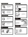
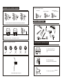
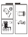
SELF LEARNING PARKING SENSOR KIT
USER MANUAL
AVRSLRN
AVRSLRN
Self Learning Parking Sensor Kit
Parking sensor system consists of 4 ultrasonic sensors, digital control MCU and buzzer.
It detects the distance between a vehicle and obstructions using the ultrasonic sensors installed
into the rear bumper (allowing tow bar fitment), with stage warning sound function. The driver
can judge the distance to avoid collisions.
MAIN FEATURES
1.
2.
3.
4.
5.
6.
7.
8.
Choose correct installation position for the sensors
Select drilling position for sensor A & D
Select drilling position for sensor B & C
Locate the position and drill
Install the sensors and hide wires
Install the buzzer
Install the control box
Connect the whole system according to the General Installation Diagram
INSTALLATION AND TEST
"BiBi" alarm sound
Hidden installation
Sensitivity adjustable switch
70dB buzzer
Fitment to vehicles with tow bar or spare wheel
NEW FEATURES
Tow Bar function
This system has a tow bar function. The system will not alarm if there is a tow bar on the rear of the vehicle.
20CM ON/OFF switch
There is an ON/OFF switch on the rear of the control module. If set to “on” the alarm distance will be 20cm
shorter than the real distance. This is designed to be used when a vehicle has a spare wheel on the rear.
The system will detect the distance between the obstacle and spare tyre rather than between obstacle and
bumper.
TECHNICAL SPECIFICATIONS
Rated Voltage: DC 12V
Operating Voltage: DC 10.5 16V
Rated Current: 20-200mA
Detecting Distance: 0.2 2.5m
Ultrasonic Frequency: 40KHz
Controller Working Temperature : -30 ~+70
Buzzer Dimensions (LxHxD) 42x42x16mm
INSTALLATION AND TEST
1. Adjust the direction of sensors and axial orientation. Neaten the wiring after installation of
sensors.
2. Connect the red controller wire to the 12v+ reverse wire on the vehicle.
Connect the black controller wire to the chassis of the vehicle.
3. Turn on vehicles ignition and select reverse gear. The system will initiate test procedure.
TEST: A. When testing some sensors, if the buzzer gives continuous sound please check that
there are no car parts or unwanted objects within the detecting range or that the sensors are not
near to strong interference sources (such as exhaust pipes or other wires) and check that the
sensors are not too tight; B. If the buzzer shows a distance but there are no objects in front of
the sensors the system may be detecting the ground, in this case please check the position of
sensors and their orientation and check that there are no car parts in the detection range; C. If
the problem still cannot be rectified the whole system should be replaced.
4. Put a board (100cm x 20cm) within 2.5m in front of the sensors. The system should start
warning procedure and sound indication of distance.
NOTE
ALARM MODE
Di stance
Awarenes s
Al ar m sou nd
1
>1.5m
Safety Ar ea
Si len ce
2
1.0-1.5m
Safety Ar ea
Bi.........Bi.........
3
0.7-0.9m
Al ar m Ar ea
Bi......Bi......
4
0.4-0.6m
Al ar m Ar ea
Bi...Bi...
5
<0.3m
Danger Area
Bi...
Stages
INSTALLATION STEPS
1. When installing the system, the vehicles engine should be off.
2. The performance of the sensors may be affected by the following situations: Heavy rain, loose
gravel roads, bumpy/ uneven roads, extreme heat or cold conditions, moist weather and if the
sensors are covered in snow, ice or mud.
3. Other ultrasonic or electronic waves may affect the performance of the system.
4. The sensors should not be installed too tight or too loose. Ensure that the supplied drill bit is
used.
5. Do not install the control unit or sensors close to other interference sources such as exhaust
pipes or vehicles wiring.
6. Test the system to make sure it operates correctly before using.
7. This system acts only as a reminding aid, in the case of any accident the manufacturer or
distributer is not responsible.
5. Sensor Installation
2. Select drilling position for sensor A & D
A. Choose a suitable drilling
position for A & D sensor
with relevant mark.
D
A. Insert the sensors into
the holes with the arrows facing up
up
Sensor
B. To perform the best
detecting angle, select the
position for A & D sensor
ideally 8-13cm away from
side, 11cm is recommended.
A
B. Hide the wires in good
order according to various
cars.
3. Select drilling position for sensor B & C
A
D
A. Measure the distance
between sensor A and D, to
get the result "L".
B. Mark sensor B & C for
every 1/3 "L" interval.
B
6. Control Box
Locate the control box in the
boot, keep safe, cool, dry
and away from shake and
interference.
A
7. Sensor Detecting
4. Drilling
2.5m
Drill with a
small bit to locate
Drill with the
supplied hole cutter
SENSOR INSTALLATION DIAGRAM
Objects that are difficult to detect
Smooth slope
Smooth round objects
Objects absorbing
wave, e.g. Cotton
INSTALLATION TOOLS
0.5-0.8m
Be sure no other parts of the vehicle fall into the detecting range of the sensors.
0.3-0.4m
0.6-0.8m
The best position for 2 sensors
The best position for 4 sensors
Pay attention to the direction of the sensor
up
1. Advised position to install the sensors
up
up
up
up
A
B
C
D
A. 4 drilled holes (A,B,C,D)
should be under the same
line.
B. 0.5-0.8m vertically high
to the ground, 0.55 is recommended
C. Vertical, tidy surface is preferred.
Vertical installation position to the ground
GENERAL INSTALLATION DIAGRAM
DETECTING RANGE
Control box
Buzzer
Top View
C
D
Reversing light
A
B
D
C
ns
Se
A
or
B
Side View
20 cm on/off function
Buzzer
ON OFF
Control box
A
B
C
D Buzzer
Power
wire
Adjust Sensitivity
)
A
B
C
D
Sensor installation height adjustable from 45 to 55cm
Buzzer