1
Programmer Manual
WCA230A & WCA280A
3 GHz & 8 GHz
Portable Wireless Communication Analyzers
071-1255-06
This document applies to firmware version 3.10
and above.
www.tektronix.com
Copyright © Tektronix, Inc. All rights reserved. Licensed software products are owned by Tektronix or its subsidiaries or
suppliers, and are protected by national copyright laws and international treaty provisions.
Tektronix products are covered by U.S. and foreign patents, issued and pending. Information in this publication supercedes
that in all previously published material. Specifications and price change privileges reserved.
TEKTRONIX and TEK are registered trademarks of Tektronix, Inc.
Contacting Tektronix
Tektronix, Inc.
14200 SW Karl Braun Drive
P.O. Box 500
Beaverton, OR 97077
USA
For product information, sales, service, and technical support:
H In North America, call 1-800-833-9200.
H Worldwide, visit www.tektronix.com to find contacts in your area.
Table of Contents
Preface . . . . . . . . . . . . . . . . . . . . . . . . . . . . . . . . . . . . . . . . . . . . . . . . . . .
ix
Related Manual . . . . . . . . . . . . . . . . . . . . . . . . . . . . . . . . . . . . . . . . . . . . . . . . . .
Difference between WCA230A and WCA280A . . . . . . . . . . . . . . . . . . . . . . . . .
ix
ix
Overview of the Manual . . . . . . . . . . . . . . . . . . . . . . . . . . . . . . . . . . . . . . . . . . . .
Connecting the Interface . . . . . . . . . . . . . . . . . . . . . . . . . . . . . . . . . . . . . . . . . . .
Using the GPIB Port . . . . . . . . . . . . . . . . . . . . . . . . . . . . . . . . . . . . . . . . . . . . . . .
Setting the GPIB Parameters from the Front Panel . . . . . . . . . . . . . . . . . . . . . . .
Using TekVISA . . . . . . . . . . . . . . . . . . . . . . . . . . . . . . . . . . . . . . . . . . . . . . . . . .
1–2
1–4
1–5
1–6
1–8
Getting Started
Syntax and Commands
Command Syntax . . . . . . . . . . . . . . . . . . . . . . . . . . . . . . . . . . . . . . . . . .
2–1
Backus-Naur Form Definition . . . . . . . . . . . . . . . . . . . . . . . . . . . . . . . . . . . . . . .
SCPI Commands and Queries . . . . . . . . . . . . . . . . . . . . . . . . . . . . . . . . . . . . . . .
IEEE 488.2 Common Commands . . . . . . . . . . . . . . . . . . . . . . . . . . . . . . . . . . . .
Constructed Mnemonics . . . . . . . . . . . . . . . . . . . . . . . . . . . . . . . . . . . . . . . . . . . .
2–1
2–2
2–10
2–11
Command Groups . . . . . . . . . . . . . . . . . . . . . . . . . . . . . . . . . . . . . . . . . .
2–13
Functional Groups . . . . . . . . . . . . . . . . . . . . . . . . . . . . . . . . . . . . . . . . . . . . . . . .
IEEE Common Commands . . . . . . . . . . . . . . . . . . . . . . . . . . . . . . . . . . . . . . . . .
:ABORt Commands . . . . . . . . . . . . . . . . . . . . . . . . . . . . . . . . . . . . . . . . . . . . . . .
:CALCulate Commands . . . . . . . . . . . . . . . . . . . . . . . . . . . . . . . . . . . . . . . . . . . .
:CALibration Commands . . . . . . . . . . . . . . . . . . . . . . . . . . . . . . . . . . . . . . . . . . .
:CONFigure Commands . . . . . . . . . . . . . . . . . . . . . . . . . . . . . . . . . . . . . . . . . . . .
:DISPlay Commands . . . . . . . . . . . . . . . . . . . . . . . . . . . . . . . . . . . . . . . . . . . . . .
:FETCh Commands . . . . . . . . . . . . . . . . . . . . . . . . . . . . . . . . . . . . . . . . . . . . . . .
:FORMat Commands . . . . . . . . . . . . . . . . . . . . . . . . . . . . . . . . . . . . . . . . . . . . . .
:HCOPy Commands . . . . . . . . . . . . . . . . . . . . . . . . . . . . . . . . . . . . . . . . . . . . . . .
:INITiate Commands . . . . . . . . . . . . . . . . . . . . . . . . . . . . . . . . . . . . . . . . . . . . . .
:INPut Commands . . . . . . . . . . . . . . . . . . . . . . . . . . . . . . . . . . . . . . . . . . . . . . . .
:INSTrument Commands . . . . . . . . . . . . . . . . . . . . . . . . . . . . . . . . . . . . . . . . . . .
:MMEMory Commands . . . . . . . . . . . . . . . . . . . . . . . . . . . . . . . . . . . . . . . . . . . .
:PROGram Commands . . . . . . . . . . . . . . . . . . . . . . . . . . . . . . . . . . . . . . . . . . . . .
:READ Commands . . . . . . . . . . . . . . . . . . . . . . . . . . . . . . . . . . . . . . . . . . . . . . . .
:SENSe Commands . . . . . . . . . . . . . . . . . . . . . . . . . . . . . . . . . . . . . . . . . . . . . . .
:STATus Commands . . . . . . . . . . . . . . . . . . . . . . . . . . . . . . . . . . . . . . . . . . . . . . .
:SYSTem Commands . . . . . . . . . . . . . . . . . . . . . . . . . . . . . . . . . . . . . . . . . . . . . .
:TRACe Commands . . . . . . . . . . . . . . . . . . . . . . . . . . . . . . . . . . . . . . . . . . . . . . .
:TRIGger Commands . . . . . . . . . . . . . . . . . . . . . . . . . . . . . . . . . . . . . . . . . . . . . .
:UNIT Commands . . . . . . . . . . . . . . . . . . . . . . . . . . . . . . . . . . . . . . . . . . . . . . . .
General Programming Procedure . . . . . . . . . . . . . . . . . . . . . . . . . . . . . . . . . . . . .
2–14
2–15
2–15
2–16
2–17
2–17
2–18
2–25
2–26
2–27
2–27
2–27
2–28
2–28
2–29
2–29
2–30
2–36
2–37
2–37
2–38
2–38
2–39
WCA230A & WCA280A Programmer Manual
i
Table of Contents
IEEE Common Commands . . . . . . . . . . . . . . . . . . . . . . . . . . . . . . . . . .
:ABORt Commands . . . . . . . . . . . . . . . . . . . . . . . . . . . . . . . . . . . . . . . .
:CALCulate Commands . . . . . . . . . . . . . . . . . . . . . . . . . . . . . . . . . . . . .
:CALibration Commands . . . . . . . . . . . . . . . . . . . . . . . . . . . . . . . . . . . .
:CONFigure Commands . . . . . . . . . . . . . . . . . . . . . . . . . . . . . . . . . . . . .
:DISPlay Commands . . . . . . . . . . . . . . . . . . . . . . . . . . . . . . . . . . . . . . . .
:FETCh Commands . . . . . . . . . . . . . . . . . . . . . . . . . . . . . . . . . . . . . . . .
:FORMat Commands . . . . . . . . . . . . . . . . . . . . . . . . . . . . . . . . . . . . . . .
:HCOPy Commands . . . . . . . . . . . . . . . . . . . . . . . . . . . . . . . . . . . . . . . .
:INITiate Commands . . . . . . . . . . . . . . . . . . . . . . . . . . . . . . . . . . . . . . .
:INPut Commands . . . . . . . . . . . . . . . . . . . . . . . . . . . . . . . . . . . . . . . . . .
:INSTrument Commands . . . . . . . . . . . . . . . . . . . . . . . . . . . . . . . . . . . .
:MMEMory Commands . . . . . . . . . . . . . . . . . . . . . . . . . . . . . . . . . . . . .
:PROGram Commands . . . . . . . . . . . . . . . . . . . . . . . . . . . . . . . . . . . . .
:READ Commands . . . . . . . . . . . . . . . . . . . . . . . . . . . . . . . . . . . . . . . . .
:SENSe Commands . . . . . . . . . . . . . . . . . . . . . . . . . . . . . . . . . . . . . . . . .
:STATus Commands . . . . . . . . . . . . . . . . . . . . . . . . . . . . . . . . . . . . . . . .
:SYSTem Commands . . . . . . . . . . . . . . . . . . . . . . . . . . . . . . . . . . . . . . .
:TRACe Commands . . . . . . . . . . . . . . . . . . . . . . . . . . . . . . . . . . . . . . . .
:TRIGger Commands . . . . . . . . . . . . . . . . . . . . . . . . . . . . . . . . . . . . . . .
:UNIT Commands . . . . . . . . . . . . . . . . . . . . . . . . . . . . . . . . . . . . . . . . . .
Retrieving Response Message . . . . . . . . . . . . . . . . . . . . . . . . . . . . . . . . .
2–41
2–51
2–53
2–69
2–77
2–91
2–245
2–293
2–295
2–299
2–303
2–309
2–313
2–323
2–329
2–369
2–521
2–529
2–539
2–545
2–557
2–559
Status and Events
Status and Event Reporting System . . . . . . . . . . . . . . . . . . . . . . . . . . . . . . . . . . .
Registers . . . . . . . . . . . . . . . . . . . . . . . . . . . . . . . . . . . . . . . . . . . . . . . . . . . . . . . .
Status Registers . . . . . . . . . . . . . . . . . . . . . . . . . . . . . . . . . . . . . . . . . . . . . . . . . .
Enable Registers . . . . . . . . . . . . . . . . . . . . . . . . . . . . . . . . . . . . . . . . . . . . . . . . . .
Transition Registers . . . . . . . . . . . . . . . . . . . . . . . . . . . . . . . . . . . . . . . . . . . . . . .
Queues . . . . . . . . . . . . . . . . . . . . . . . . . . . . . . . . . . . . . . . . . . . . . . . . . . . . . . . . .
Status and Event Processing Sequence . . . . . . . . . . . . . . . . . . . . . . . . . . . . . . . .
Synchronizing Execution . . . . . . . . . . . . . . . . . . . . . . . . . . . . . . . . . . . . . . . . . . .
3–1
3–5
3–5
3–9
3–11
3–12
3–13
3–14
Error Messages and Codes . . . . . . . . . . . . . . . . . . . . . . . . . . . . . . . . . . .
3–17
Command Errors . . . . . . . . . . . . . . . . . . . . . . . . . . . . . . . . . . . . . . . . . . . . . . . . .
Execution Errors . . . . . . . . . . . . . . . . . . . . . . . . . . . . . . . . . . . . . . . . . . . . . . . . .
Device Specific Errors . . . . . . . . . . . . . . . . . . . . . . . . . . . . . . . . . . . . . . . . . . . . .
Query Errors . . . . . . . . . . . . . . . . . . . . . . . . . . . . . . . . . . . . . . . . . . . . . . . . . . . . .
3–18
3–20
3–22
3–22
Programming Examples
Application Program Sample . . . . . . . . . . . . . . . . . . . . . . . . . . . . . . . . . . . . . . . .
Macro Program Execution Sample . . . . . . . . . . . . . . . . . . . . . . . . . . . . . . . . . . .
ii
4–2
4–14
WCA230A & WCA280A Programmer Manual
Table of Contents
Appendices
Appendix A: Character Charts . . . . . . . . . . . . . . . . . . . . . . . . . . . . . . .
Appendix B: GPIB Interface Specification . . . . . . . . . . . . . . . . . . . . . .
A–1
B–1
Interface Functions . . . . . . . . . . . . . . . . . . . . . . . . . . . . . . . . . . . . . . . . . . . . . . . .
Interface Messages . . . . . . . . . . . . . . . . . . . . . . . . . . . . . . . . . . . . . . . . . . . . . . . .
B–1
B–3
Appendix C: Factory Initialization Settings . . . . . . . . . . . . . . . . . . . . .
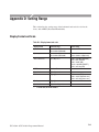
Appendix D: Setting Range . . . . . . . . . . . . . . . . . . . . . . . . . . . . . . . . . .
C–1
D–1
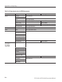
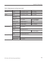
Display Format and Scale . . . . . . . . . . . . . . . . . . . . . . . . . . . . . . . . . . . . . . . . . .
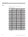
RBW . . . . . . . . . . . . . . . . . . . . . . . . . . . . . . . . . . . . . . . . . . . . . . . . . . . . . . . . . . .
D–1
D–4
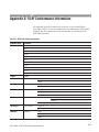
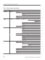
Appendix E: SCPI Conformance Information . . . . . . . . . . . . . . . . . . .
E–1
Glossary and Index
WCA230A & WCA280A Programmer Manual
iii
Table of Contents
List of Figures
iv
Figure 1–1: Command parts . . . . . . . . . . . . . . . . . . . . . . . . . . . . . . . . . .
Figure 1–2: Functional groupings and an alphabetical list of
commands . . . . . . . . . . . . . . . . . . . . . . . . . . . . . . . . . . . . . . . . . . . . .
Figure 1–3: Event-driven program . . . . . . . . . . . . . . . . . . . . . . . . . . . .
Figure 1–4: Sample program (Visual C++ source code) . . . . . . . . . . .
Figure 1–5: GPIB connector (rear panel) . . . . . . . . . . . . . . . . . . . . . . .
Figure 1–6: GPIB connection . . . . . . . . . . . . . . . . . . . . . . . . . . . . . . . . .
Figure 1–7: Typical GPIB network configurations . . . . . . . . . . . . . . .
Figure 1–8: Remote Setup menu . . . . . . . . . . . . . . . . . . . . . . . . . . . . . .
Figure 1–9: Setting the GPIB parameters . . . . . . . . . . . . . . . . . . . . . . .
1–2
Figure 2–1: Example of SCPI subsystem hierarchy tree . . . . . . . . . . .
Figure 2–2: Example of abbreviating a command . . . . . . . . . . . . . . . .
Figure 2–3: Example of chaining commands and queries . . . . . . . . . .
Figure 2–4: Example of omitting root and lower-level nodes in a
chained message . . . . . . . . . . . . . . . . . . . . . . . . . . . . . . . . . . . . . . . .
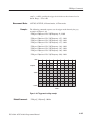
Figure 2–5: View number assignments . . . . . . . . . . . . . . . . . . . . . . . . .
Figure 2–6: Horizontal scale setting requirements . . . . . . . . . . . . . . . .
Figure 2–7: Horizontal scale setting requirements for spectrum
view . . . . . . . . . . . . . . . . . . . . . . . . . . . . . . . . . . . . . . . . . . . . . . . . . . .
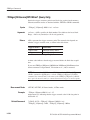
Figure 2–8: :DISPlay:CCDF command setting . . . . . . . . . . . . . . . . . .
Figure 2–9: :DISPlay:DDEMod command setting . . . . . . . . . . . . . . . .
Figure 2–10: :DISPlay:OVIew command setting . . . . . . . . . . . . . . . . .
Figure 2–11: :DISPlay:PULSe:SPECtrum command setting . . . . . . .
Figure 2–12: :DISPlay:SPECtrum command setting . . . . . . . . . . . . .
Figure 2–13: :DISPlay:TFRequency command setting . . . . . . . . . . . .
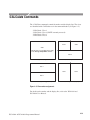
Figure 2–14: View display formats . . . . . . . . . . . . . . . . . . . . . . . . . . . .
Figure 2–15: :DISPlay:WAVeform command setting . . . . . . . . . . . . . .
Figure 2–16: Setting up the ACPR measurement . . . . . . . . . . . . . . . .
Figure 2–17: Defining the analysis range . . . . . . . . . . . . . . . . . . . . . . .
Figure 2–18: Setting up the channel power measurement . . . . . . . . .
Figure 2–19: Setting up the C/N measurement . . . . . . . . . . . . . . . . . . .
Figure 2–20: Defining the analysis range . . . . . . . . . . . . . . . . . . . . . . .
Figure 2–21: Setting up the EBW measurement . . . . . . . . . . . . . . . . .
Figure 2–22: Setting frequency and span . . . . . . . . . . . . . . . . . . . . . . .
Figure 2–23: Setting up the OBW measurement . . . . . . . . . . . . . . . . .
2–2
2–6
2–7
1–2
1–3
1–3
1–4
1–5
1–5
1–6
1–7
2–7
2–53
2–92
2–93
2–94
2–102
2–130
2–152
2–186
2–229
2–239
2–240
2–372
2–374
2–389
2–392
2–402
2–421
2–423
2–433
WCA230A & WCA280A Programmer Manual
Table of Contents
Figure 2–24: Setting up the spurious signal measurement . . . . . . . . .
Figure 2–25: Defining the analysis range . . . . . . . . . . . . . . . . . . . . . . .
Figure 2–26: Trigger mask setting example . . . . . . . . . . . . . . . . . . . . .
Figure 2–27: Retrieving response message . . . . . . . . . . . . . . . . . . . . . .
2–489
2–517
2–547
2–559
Figure 3–1: Status/Event reporting mechanism . . . . . . . . . . . . . . . . . .
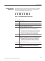
Figure 3–2: The Status Byte Register (SBR) . . . . . . . . . . . . . . . . . . . . .
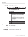
Figure 3–3: The Standard Event Status Register (SESR) . . . . . . . . . .
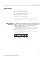
Figure 3–4: The Operation Condition Register (OCR) . . . . . . . . . . . .
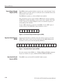
Figure 3–5: The Event Status Enable Register (ESER) . . . . . . . . . . . .
Figure 3–6: The Service Request Enable Register (SRER) . . . . . . . . .
Figure 3–7: Operation Enable Register (OENR) . . . . . . . . . . . . . . . . .
Figure 3–8: Operation Transition Register (OTR) . . . . . . . . . . . . . . . .
Figure 3–9: Status and event processing sequence . . . . . . . . . . . . . . . .
3–2
3–6
3–7
3–8
3–9
3–10
3–10
3–11
3–13
Figure 4–1: Saving the macro programs . . . . . . . . . . . . . . . . . . . . . . . .
4–14
WCA230A & WCA280A Programmer Manual
v
Table of Contents
List of Tables
Table 2–1: BNF symbols and meanings . . . . . . . . . . . . . . . . . . . . . . . .
Table 2–2: Query response examples . . . . . . . . . . . . . . . . . . . . . . . . . .
Table 2–3: Parameter types used in syntax descriptions . . . . . . . . . .
Table 2–4: Available units . . . . . . . . . . . . . . . . . . . . . . . . . . . . . . . . . . .
Table 2–5: Available SI prefixes . . . . . . . . . . . . . . . . . . . . . . . . . . . . . .
Table 2–6: Constructed mnemonics . . . . . . . . . . . . . . . . . . . . . . . . . . .
Table 2–7: Measurement mode . . . . . . . . . . . . . . . . . . . . . . . . . . . . . . .
Table 2–8: List of command groups . . . . . . . . . . . . . . . . . . . . . . . . . . .
Table 2–9: IEEE common commands . . . . . . . . . . . . . . . . . . . . . . . . . .
Table 2–10: :ABORt commands . . . . . . . . . . . . . . . . . . . . . . . . . . . . . .
Table 2–11: :CALCulate commands . . . . . . . . . . . . . . . . . . . . . . . . . . .
Table 2–12: :CALibration commands . . . . . . . . . . . . . . . . . . . . . . . . .
Table 2–13: :CONFigure commands . . . . . . . . . . . . . . . . . . . . . . . . . .
Table 2–14: :DISPlay commands . . . . . . . . . . . . . . . . . . . . . . . . . . . . .
Table 2–15: :FETCh commands . . . . . . . . . . . . . . . . . . . . . . . . . . . . . .
Table 2–16: :FORMat commands . . . . . . . . . . . . . . . . . . . . . . . . . . . . .
Table 2–17: :HCOPy commands . . . . . . . . . . . . . . . . . . . . . . . . . . . . . .
Table 2–18: :INITiate commands . . . . . . . . . . . . . . . . . . . . . . . . . . . . .
Table 2–19: :INPut commands . . . . . . . . . . . . . . . . . . . . . . . . . . . . . . .
Table 2–20: :INSTrument commands . . . . . . . . . . . . . . . . . . . . . . . . . .
Table 2–21: :MMEMory commands . . . . . . . . . . . . . . . . . . . . . . . . . . .
Table 2–22: :PROGram commands . . . . . . . . . . . . . . . . . . . . . . . . . . .
Table 2–23: :READ commands . . . . . . . . . . . . . . . . . . . . . . . . . . . . . . .
Table 2–24: :SENSe commands . . . . . . . . . . . . . . . . . . . . . . . . . . . . . . .
Table 2–25: :STATus commands . . . . . . . . . . . . . . . . . . . . . . . . . . . . . .
Table 2–26: :SYSTem commands . . . . . . . . . . . . . . . . . . . . . . . . . . . . .
Table 2–27: :TRACe commands . . . . . . . . . . . . . . . . . . . . . . . . . . . . . .
Table 2–28: :TRIGger commands . . . . . . . . . . . . . . . . . . . . . . . . . . . . .
Table 2–29: :UNIT commands . . . . . . . . . . . . . . . . . . . . . . . . . . . . . . . .
Table 2–30: :DISPlay command subgroups . . . . . . . . . . . . . . . . . . . . .
Table 2–31: Main view display formats . . . . . . . . . . . . . . . . . . . . . . . .
Table 2–32: Subview display formats . . . . . . . . . . . . . . . . . . . . . . . . . .
Table 2–33: Subview display format . . . . . . . . . . . . . . . . . . . . . . . . . . .
Table 2–34: Subview display formats . . . . . . . . . . . . . . . . . . . . . . . . . .
Table 2–35: Subview display formats in the signal source analysis . .
vi
2–1
2–3
2–4
2–8
2–8
2–11
2–13
2–14
2–15
2–15
2–16
2–17
2–17
2–18
2–25
2–26
2–27
2–27
2–27
2–28
2–28
2–29
2–29
2–30
2–36
2–37
2–37
2–38
2–38
2–91
2–105
2–119
2–148
2–170
2–206
WCA230A & WCA280A Programmer Manual
Table of Contents
Table 2–36: Queried information on the digital modulation analysis
results . . . . . . . . . . . . . . . . . . . . . . . . . . . . . . . . . . . . . . . . . . . . . . . .
Table 2–37: Queried information . . . . . . . . . . . . . . . . . . . . . . . . . . . . .
Table 2–38: RFID analysis . . . . . . . . . . . . . . . . . . . . . . . . . . . . . . . . . . .
Table 2–39: Signal source analysis . . . . . . . . . . . . . . . . . . . . . . . . . . . .
Table 2–40: Input attenuation settings . . . . . . . . . . . . . . . . . . . . . . . . .
Table 2–41: Mixer level settings . . . . . . . . . . . . . . . . . . . . . . . . . . . . . .
Table 2–42: Reference level range . . . . . . . . . . . . . . . . . . . . . . . . . . . . .
Table 2–43: Measurement mode . . . . . . . . . . . . . . . . . . . . . . . . . . . . . .
Table 2–44: Queried information on the digital modulation analysis
results . . . . . . . . . . . . . . . . . . . . . . . . . . . . . . . . . . . . . . . . . . . . . . . .
Table 2–45: Signal source analysis . . . . . . . . . . . . . . . . . . . . . . . . . . . .
Table 2–46: :SENSe command subgroups . . . . . . . . . . . . . . . . . . . . . .
Table 2–47: Measurement item selections . . . . . . . . . . . . . . . . . . . . . .
Table 2–48: Block size setting range . . . . . . . . . . . . . . . . . . . . . . . . . . .
Table 2–49: Modulation selections . . . . . . . . . . . . . . . . . . . . . . . . . . . .
Table 2–50: Communication standard selections . . . . . . . . . . . . . . . .
Table 2–51: Measurement frequency bands . . . . . . . . . . . . . . . . . . . .
Table 2–52: Span setting . . . . . . . . . . . . . . . . . . . . . . . . . . . . . . . . . . . .
Table 2–53: RFID measurement items . . . . . . . . . . . . . . . . . . . . . . . . .
Table 2–54: Decoding format . . . . . . . . . . . . . . . . . . . . . . . . . . . . . . . .
Table 2–55: Modulation format . . . . . . . . . . . . . . . . . . . . . . . . . . . . . .
Table 2–56: Demodulation standard . . . . . . . . . . . . . . . . . . . . . . . . . . .
Table 2–57: FFT windows . . . . . . . . . . . . . . . . . . . . . . . . . . . . . . . . . . .
Table 2–58: S/A mode measurement items . . . . . . . . . . . . . . . . . . . . . .
Table 2–59: Analysis length setting range . . . . . . . . . . . . . . . . . . . . . .
Table 2–60: SSOurce measurement items . . . . . . . . . . . . . . . . . . . . . .
Table 2–61: Bin number setting range . . . . . . . . . . . . . . . . . . . . . . . . .
2–338
2–362
2–369
2–378
2–383
2–409
2–418
2–424
2–430
2–453
2–456
2–457
2–461
2–482
2–484
2–504
2–505
2–546
Table 3–1: SBR bit functions . . . . . . . . . . . . . . . . . . . . . . . . . . . . . . . . .
Table 3–2: SESR bit functions . . . . . . . . . . . . . . . . . . . . . . . . . . . . . . . .
Table 3–3: OCR bit functions . . . . . . . . . . . . . . . . . . . . . . . . . . . . . . . .
Table 3–4: Command errors . . . . . . . . . . . . . . . . . . . . . . . . . . . . . . . . .
Table 3–5: Execution errors . . . . . . . . . . . . . . . . . . . . . . . . . . . . . . . . . .
Table 3–6: Device specific errors . . . . . . . . . . . . . . . . . . . . . . . . . . . . . .
Table 3–7: Query errors . . . . . . . . . . . . . . . . . . . . . . . . . . . . . . . . . . . . .
3–6
3–7
3–8
3–18
3–20
3–22
3–22
Table A–1: ASCII & GPIB code chart . . . . . . . . . . . . . . . . . . . . . . . . . .
A–2
Table B–1: GPIB interface function implementation . . . . . . . . . . . . .
B–1
WCA230A & WCA280A Programmer Manual
2–254
2–261
2–268
2–281
2–304
2–307
2–308
2–310
vii
Table of Contents
Table B–2: Standard interface messages . . . . . . . . . . . . . . . . . . . . . . .
viii
B–3
Table C–1: Factory initialization settiings — IEEE common
commands . . . . . . . . . . . . . . . . . . . . . . . . . . . . . . . . . . . . . . . . . . . . .
Table C–2: Factory initialization settiings — :CALCulate
commands . . . . . . . . . . . . . . . . . . . . . . . . . . . . . . . . . . . . . . . . . . . . .
Table C–3: Factory initialization settiings — :CALibration
commands . . . . . . . . . . . . . . . . . . . . . . . . . . . . . . . . . . . . . . . . . . . . .
Table C–4: Factory initialization settiings — :DISPlay commands .
Table C–5: Factory initialization settiings — :FORMat commands .
Table C–6: Factory initialization settiings — :INITiate commands .
Table C–7: Factory initialization settiings — :INPut commands . . .
Table C–8: Factory initialization settiings — :SENSe commands . . .
Table C–9: Factory initialization settiings — :STATus commands . .
Table C–10: Factory initialization settiings — :TRACe commands .
Table C–11: Factory initialization settiings — :TRIGger commands
Table C–12: Factory initialization settings — :UNIT commands . . .
C–1
C–2
C–7
C–7
C–7
C–8
C–13
C–14
C–14
C–14
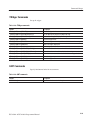
Table D–1: Display format and scale . . . . . . . . . . . . . . . . . . . . . . . . . .
Table D–2: Display format and scale: RFID Measurements . . . . . . .
Table D–3: Display format and scale: Signal source analysis . . . . . .
Table D–4: RBW setting range . . . . . . . . . . . . . . . . . . . . . . . . . . . . . . .
D–1
D–2
D–3
D–4
Table E–1: SCPI 1999.0-defined commands . . . . . . . . . . . . . . . . . . . .
E–1
C–1
C–1
WCA230A & WCA280A Programmer Manual
Preface
This programmer manual is for the WCA230A and WCA280A Portable Wireless
Communication Analyzers. It provides information on operating your analyzer
using the General Purpose Interface Bus (GPIB).
This manual is composed of the following sections:
H
Getting Started outlines how to use the GPIB interface.
H
Syntax and Commands defines the syntax used in command descriptions,
presents a list of all command subsystems, and presents detailed descriptions
of all programming commands.
H
Status and Events describes how the status and Events Reporting system
operates and presents a list of all system errors.
H
Programming Examples describes some example analyzer programs.
H
Appendices provides additional information including character charts, GPIB
interface specification, and factory initialization settings.
Related Manual
WCA230A and WCA280A User Manual
(Standard accessory; Tektronix part number 071-1253-XX)
Describes how to install the analyzer and how to work with the menus and
details the functions.
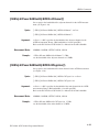
Difference between WCA230A and WCA280A
WCA230A and WCA280A have the same functions except for their measurement frequency ranges:
WCA230A . . . . . . . . . DC to 3 GHz
WCA280A . . . . . . . . . DC to 8 GHz
Unless otherwise noted, descriptions in this manual apply to both.
WCA230A & WCA280A Programmer Manual
ix
Preface
x
WCA230A & WCA280A Programmer Manual
Getting Started
Getting Started
You can write computer programs that remotely set the analyzer front panel
controls or that take measurements and read those measurements for further
analysis or storage.
To help you get started with programming the analyzer, this section includes the
following sections:
H
Overview of the Manual
Summarizes the type of programming information contained in each major
section of this manual.
H
Connecting the Interface
Describes how to physically connect the analyzer to a controller.
H
Using GPIB Ports
Describes how to use the GPIB port.
H
Setting the GPIB Parameters from the Front Panel
Describes how to set the GPIB parameters from the front panel.
H
Using TekVISA
Describes how to use the TekVISA communication protocol.
WCA230A & WCA280A Programmer Manual
1-1
Getting Started
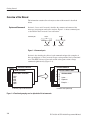
Overview of the Manual
The information contained in each major section of this manual is described
below.
Syntax and Commands
Section 2, Syntax and Commands, describes the structure and content of the
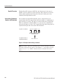
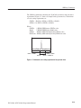
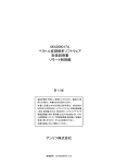
messages your program sends to the analyzer. Figure 1–1 shows command parts
as described in the Command Syntax subsection.
Command parts
Header
Comma
:MMEMory:COPY
FILE1,FILE2
Mnemonics
Space
Arguments
Figure 1-1: Command parts
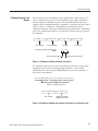
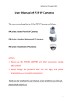
Section 2 also describes the effect of each command and provides examples of
how you might use it. The Command Groups section provides lists by functional
areas. The IEEE Common Commands and the subsequent sections arrange
commands alphabetically (Figure 1–2).
:TRIGger
:CALCulate:MARKer:X
:CALCulate Commands
:ABORt Commands
S
IEEE Common Commands
*CAL?
*CLS
*ESE
*ESR
*IDN?
*OPC
:CALCulate:MARKer:AOFF
:CALCulate:DLINe
A
S
E
A
Syntax: . . .
E
Arguments:
Examples: . . .
Commands grouped in functional areas
Commands listed alphabetically
Figure 1-2: Functional groupings and an alphabetical list of commands
1-2
WCA230A & WCA280A Programmer Manual
Getting Started
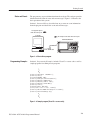
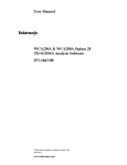
Status and Events
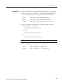
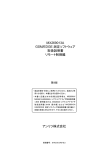
The program may request information from the analyzer. The analyzer provides
information in the form of status and error messages. Figure 1–3 illustrates the
basic operation of this system.
Section 3, Status and Events, describes how to get status or event information
from the program and details the event and error messages.
Your program requests
status and event reports.
Controller
The analyzer sends status and event reports.
WCA230A/WCA280A
GPIB cable
Figure 1-3: EventĆdriven program
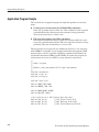
Programming Examples
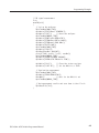
Section 4, Programming Examples, includes Visual C++ source code as well as
sample programs for running macro programs.
GpibWrite("INSTrument 'SANORMAL'");
GpibWrite("*RST");
GpibTimeOut(NORMAL_TIME);
GpibWrite("CONFigure:SPECtrum:CHPower");
GpibWrite("FREQuency:BAND RF1B");
GpibWrite("FREQuency:CENTer 1GHz");
GpibWrite("FREQuency:SPAN 1MHz");
GpibWrite("*CAL?");
GpibRead(readBuf, MAX_BUF);
printf("*CAL? result = %s\n", readBuf);
GpibWrite("CHPower:BANDwidth:INTegration 300kHz");
GpibWrite("SPECtrum:AVERage ON");
Figure 1-4: Sample program (Visual C++ source code)
WCA230A & WCA280A Programmer Manual
1-3
Getting Started
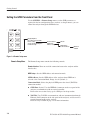
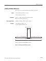
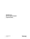
Connecting the Interface
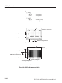
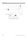
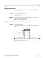
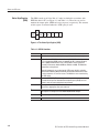
The analyzer has a 24-pin GPIB connector on its rear panel, as shown in
Figure 1–5. This connector has a D-type shell and conforms to IEEE Std
488.1–1987.
Attach an IEEE Std 488.1-1987 GPIB cable (Tektronix part number
012-0991-00) to this connector.
GPIB connector
Figure 1-5: GPIB connector (rear panel)
Appendix B: GPIB Interface Specifications gives more information on the GPIB
configuration of the analyzer.
For the other interfaces, refer to the WCA230A and WCA280A User Manual.
1-4
WCA230A & WCA280A Programmer Manual
Getting Started
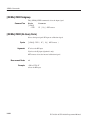
Using the GPIB Port
The analyzer has Talker/Listener functions through which it can communicate
with other devices, as well as the external controller, located on the bus.
GPIB
Controller
Using the analyzer as a talker or listener
Figure 1-6: GPIB connection
GPIB Requirements
Observe these rules when you use your analyzer with a GPIB network:
H
Assign a unique device address to each device on the bus. No two devices
can share the same device address.
H
Do not connect more than 15 devices to any one bus.
H
Connect one device for every 2 meters (6 feet) of cable used.
H
Do not use more than 20 meters (65 feet) of cable to connect devices to a
bus.
H
Turn on at least two-thirds of the devices on the network while using the
network.
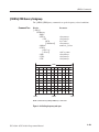
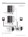
H
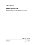
Connect the devices on the network in a star or linear configuration as shown
in Figure 1–7. Do not use loop or parallel configurations.
GPIB Device
GPIB Device
GPIB Device
GPIB Device
GPIB Device
GPIB Device
GPIB Device
Figure 1-7: Typical GPIB network configurations
WCA230A & WCA280A Programmer Manual
1-5
Getting Started
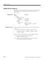
Setting the GPIB Parameters from the Front Panel
Use the SYSTEM → Remote Setup menu to set the GPIB parameters as
required for the bus configuration. Once you have set the parameters, you can
control the analyzer through the GPIB interface.
Display Brightness
Reset All to Factory Defaults
Remote Setup...
Version and Installed Options...
Instrument Setup...
Remote Interface
GPIB Setup...
Ethernet Setup...
Off / On
GPIB Address
Connection Mode...
GPIB Port
TekVISA
Figure 1-8: Remote Setup menu
Remote Setup Menu
The Remote Setup menu contains the following controls:
Remote Interface. Turns on or off the connection between the analyzer and the
interface bus.
GPIB Setup... Sets the GPIB address and connection mode.
GPIB Address. Sets the GPIB address of the analyzer when GPIB Port is
selected as the Connection Mode. Range: 0 to 30 (default: 1)
Connection Mode. Selects the physical GPIB port or the virtual (TekVISA)
connection method.
1-6
H
GPIB Port. Default. Uses the IEEE488.2 connector on the rear panel of the
analyzer to communicate with an external controller.
Refer to the next section Setting up the GPIB port for the procedure.
H
TekVISA. Uses TekVISA to communicate with test instrumentation through
Ethernet (LAN connector on the side panel of the analyzer), and also to run a
control program locally on the analyzer.
Refer to Using TekVISA on page 1–8 for more information.
WCA230A & WCA280A Programmer Manual
Getting Started
Ethernet Setup... Not available currently. Use the Windows XP Control Panel to
set up networking parameters.
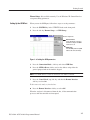
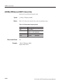
Setting Up the GPIB Port
When you use the GPIB port, follow these steps to set the parameters:
1. Press the SYSTEM key in the UTILITY block on the front panel.
2. Press the side key Remote Setup...→ GPIB Setup...
Remote Setup menu
Remote Interface
Selects whether the connection
between the analyzer and GPIB
is turned on or off.
GPIB Setup...
Sets the GPIB parameters (GPIB
address and connection mode).
Figure 1-9: Setting the GPIB parameters
3. Press the Connection Mode... side key and select GPIB Port.
4. Press the GPIB Address side key and set the address using either the
general purpose knob or the numeric keypad.
NOTE. The GPIB address cannot be initialized with *RST command.
5. Press the Cancel–Back (top) side key and then the Remote Interface
side key to select On.
To disconnect the analyzer from the bus:
H
Press the Remote Interface side key to select Off.
When the analyzer is disconnected from the bus, all the communication
processes with the controller are interrupted.
WCA230A & WCA280A Programmer Manual
1-7
Getting Started
Using TekVISA
TekVISA is Tektronix implementation of VISA (Virtual Instrument Software
Architecture), an industry-standard communication protocol. It allows you to
write programs using the WCA200A Series SCPI command set to control the
instrument through interfaces besides the built-in IEEE 488.2 port. Programs are
written to execute on the local or remote controller. The WCA200A Series
implementation of TekVISA includes a subset of the TekVISA functionality
offered on Tektronix oscilloscopes. The Virtual GPIB (GPIB8), GPIB, and LAN
(VXI-11 protocol) interfaces are supported, but not the ASRL interface.
NOTE. The details on TekVISA concepts and operations are explained in the
TekVISA Programmer Manual. Refer to Installing TekVISA described below for
accessing the files.
Be aware of the following points:
Installing TekVISA
H
If TekVISA is not installed or has not been activated, and you select
TekVISA as the connection mode, the instrument still attempts to connect to
TekVISA. This does not hang up the instrument, but the GPIB port is taken
off-line until you select GPIB Port as the connection mode again.
H
Applications which are designed to execute locally on the instrument need to
share the Windows processor with the measurement calculation software of
the analyzer. If the controller application is very compute-intensive, it will
slow down the analyzer application significantly.
The TekVISA tools are not installed when you receive the instrument.
Use the following procedure to install the tools.
To use TekVISA, these conditions must be satisfied:
1-8
H
Windows XP is used as the instrument’s operating system.
Instruments using Windows 98SE must be upgraded to Windows XP for
TekVISA to operate properly.
H
A TekVISA-compatible version of the analyzer application is installed and
running on the instrument. Version must be greater than 3.00.000.
H
TekVISA is installed on the instrument. Version 2.03 is recommended.
WCA230A & WCA280A Programmer Manual
Getting Started
The TekVISA-related files are on the internal hard disk of the analyzer
in these directories:
H
C:\Tektronix\TekVISA\installer contains the TekVISA installer.
H
C:\Tektronix\TekVISA\manual contains the TekVISA Programmer Manual.
Use the following steps to install the TekVISA tools on your analyzer:
NOTE. For details on accessing Windows XP on the analyzer, refer to the
WCA230A and WCA280A User Manual.
1. Connect a USB mouse and keyboard to the USB ports on the side panel of
the analyzer.
2. Display the Windows XP desktop on the screen.
3. Find the setup.exe file in the C:\Tektronix\TekVISA\installer directory
using Windows Explorer or other file access methods.
4. Run setup.exe and follow the instructions.
The TekVISA Programmer Manual is found in the C:\Tektronix\TekVISA\manual
directory.
WCA230A & WCA280A Programmer Manual
1-9
Getting Started
1-10
WCA230A & WCA280A Programmer Manual
Syntax and Commands
Command Syntax
This section contains information on the Standard Commands for Programmable
Instruments (SCPI) and IEEE 488.2 Common Commands you can use to
program your WCA230A/WCA280A analyzer. The information is organized in
the following subsections:
H
Backus-Naur Form Definition
H
SCPI Commands and Queries
H
IEEE 488.2 Common Commands
H
Constructed Mnemonics
BackusĆNaur Form Definition
This manual may describe commands and queries using the Backus-Naur Form
(BNF) notation. Table 2–1 defines the standard BNF symbols:
Table 2-1: BNF symbols and meanings
Symbol
Meaning
<ą>
Defined element
::=
Is defined as
|
Exclusive OR
{ą}
Group; one element is required
[ą]
Optional; can be omitted
.ă.Ă.
Previous element(s) may be repeated
(ą)
Comment
WCA230A & WCA280A Programmer Manual
2-1
Command Syntax
SCPI Commands and Queries
SCPI is a standard created by a consortium that provides guidelines for remote
programming of instruments. These guidelines provide a consistent programming environment for instrument control and data transfer. This environment
uses defined programming messages, instrument responses, and data format
across all SCPI instruments, regardless of manufacturer. The analyzer uses a
command language based on the SCPI standard.
The SCPI language is based on a hierarchical or tree structure (see Figure 2–1)
that represents a subsystem. The top level of the tree is the root node; it is
followed by one or more lower-level nodes.
LEVel
TRIGger
Root node
SEQuence
LowerĆlevel nodes
POLarity
SOURce
Figure 2-1: Example of SCPI subsystem hierarchy tree
You can create commands and queries from these subsystem hierarchy trees.
Commands specify actions for the instrument to perform. Queries return
measurement data and information about parameter settings.
2-2
WCA230A & WCA280A Programmer Manual
Command Syntax
Creating Commands
SCPI commands are created by stringing together the nodes of a subsystem
hierarchy and separating each node by a colon.
In Figure 2–1, TRIGger is the root node and SEQuence, LEVel, POLarity, and
SOURce are lower-level nodes. To create a SCPI command, start with the root
node TRIGger and move down the tree structure adding nodes until you reach
the end of a branch. Most commands and some queries have parameters; you
must include a value for these parameters. If you specify a parameter value that
is out of range, the parameter will be set to a default value. The command
descriptions, which start on page 2–41, list the valid values for all parameters.
For example, TRIGger:SEQuence:SOURce EXT is a valid SCPI command
created from the hierarchy tree in Figure 2–1.
Creating Queries
Query Responses
To create a query, start at the root node of a tree structure, move down to the end
of a branch, and add a question mark. TRIGger:SEQuence:SOURce? is an
example of a valid SCPI query using the hierarchy tree in Figure 2–1.
The query causes the analyzer to return information about its status or settings.
When a query is sent to the analyzer, only the values are returned. When the
returned value is a mnemonic, it is noted in abbreviated format, as shown in
Table 2–2.
Table 2-2: Query response examples
Query
Response
:DISPlay:OVIew:SGRam:X:SPAN?
10.0E+6
:SENSe:AVERage:TYPE?
RMS
A few queries also initiate an operation action before returning information. For
example, the *CAL? query runs a calibration.
WCA230A & WCA280A Programmer Manual
2-3
Command Syntax
Parameter Types
Every parameter in the command and query descriptions is of a specified type.
The parameters are enclosed in brackets, such as <value>. The parameter type is
listed after the parameter and is enclosed in parentheses, for example, (discrete).
Some parameter types are defined specifically for the WCA200A Series
command set and some are defined by ANSI/IEEE 488.2-1987 (refer to
Table 2–3).
Table 2-3: Parameter types used in syntax descriptions
2-4
Parameter type
Description
Example
arbitrary block1
A specified length of arbitrary data
#512234xxxxx . . .
where 5 indicates that the followĆ
ing 5 digits (12234) specify the
length of the data in bytes;
xxxxx ... indicates the data
boolean
Boolean numbers or values
ON or 1; OFF or 0
discrete
A list of specific values
MIN, MAX, UP, DOWN
binary
Binary numbers
#B0110
octal
Octal numbers
#Q57, #Q3
hexadecimal2
Hexadecimal numbers
(0-9, A, B, C, D, E, F)
#HAA, #H1
NR12,3 numeric
Integers
0, 1, 15, -1
NR22 numeric
Decimal numbers
1.2, 3.141516, -6.5
NR32 numeric
Floating point numbers
3.1415E-9, -16.1E5
NRf2 numeric
Flexible decimal number that may
be type NR1, NR2 or NR3
See NR1, NR2, and NR3 examĆ
ples
string4
Alphanumeric characters
(must be within quotation marks)
Testing 1, 2, 3"
1
Defined in ANSI/IEEE 488.2 as Definite Length Arbitrary Block Response Data."
2
An ANSI/IEEE 488.2-1992Ćdefined parameter type.
3
Some commands and queries will accept an octal or hexadecimal value even though
the parameter type is defined as NR1.
4
Defined in ANSI/IEEE 488.2 as String Response Data."
WCA230A & WCA280A Programmer Manual
Command Syntax
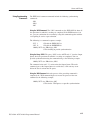
SCPIĆdefined Parameters. In addition to the ANSI/IEEE 488.2-1987-defined
parameters, WCA200A Series support the following SCPI-defined parameters.
H
<NRf> for boolean
OFF | ON | 0 | 1 | <NRf>
You can use <NRf> for boolean parameter. The values other than zero (OFF)
are regarded as one (ON).
H
MAXimum and MINimum for numeric parameters
You can use MAXimum and MINimum for the numeric parameter <NRf>.
The following example sets the trigger level to the maximum (100%).
:TRIGger[:SEQuence]:LEVel:IF MAXimum
The commands that have numeric parameters support the following query:
<header>? { MAXimum | MINimum }
The query command returns the maximum or minimum acceptable value for
the command. For example,
:TRIGger[:SEQuence]:LEVel:IF? MAXimum
returns 100 indicating the maximum trigger level is 100%.
H
UP and DOWN for numeric parameters
The [:SENse]:FREQuency:CENTer command (refer to page 2–425) supports
UP and DOWN for the numeric parameters. The increment/decrement of
UP/DOWN is determined by one of these commands:
[:SENse]:FREQuency:CENTer:STEP:AUTO
[:SENse]:FREQuency:CENTer:STEP[:INCRement]
WCA230A & WCA280A Programmer Manual
2-5
Command Syntax
Special Characters
Abbreviating Commands,
Queries, and Parameters
The Line Feed (LF) character (ASCII 10), and all characters in the range of
ASCII 127-255 are defined as special characters. These characters are used in
arbitrary block arguments only; using these characters in other parts of any
command yields unpredictable results.
You can abbreviate most SCPI commands, queries, and parameters to an
accepted short form. This manual shows these short forms as a combination of
upper and lower case letters. The upper case letters indicate the accepted short
form of a command. As shown in Figure 2–2, you can create a short form by
using only the upper case letters. The accepted short form and the long form are
equivalent and request the same action of the instrument.
Long form of a command
:CALCulate3:MARKer:Y 50
Minimum information needed for
accepted short form
Accepted short form of a
command and parameter
CALC3:MARK:Y 50
Figure 2-2: Example of abbreviating a command
NOTE. The numeric suffix of a command or query may be included in either the
long form or short form; the analyzer will default to “1” if no suffix is used. In
Figure 2–2, the “3” of “CALC3” indicates that the command is directed to
View 3.
2-6
WCA230A & WCA280A Programmer Manual
Command Syntax
Chaining Commands and
Queries
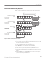
You can chain several commands or queries together into a single message. To
create a chained message, first create a command or query, add a semicolon (;),
and then add more commands or queries and semicolons until the message is
complete. If the command following a semicolon is a root node, precede it with a
colon (:). Figure 2–3 illustrates a chained message consisting of several
commands and queries. The single chained message should end in a command or
query, not a semicolon. Responses to any queries in your message are separated
by semicolons.
:CALC:MARK:XĂ100;:SENS:AVER:STATĂON;:DISP:WAV:Y:PDIV?;:READ:SPEC:CFR?
First command
Second command
First query
The response from this chained message
might be
100;1.2E+9
Response from first query
Second query
Response from second query
Figure 2-3: Example of chaining commands and queries
If a command or query has the same root and lower-level nodes as the previous
command or query, you can omit these nodes. In Figure 2–4, the second
command has the same root node (TRIG:SEQuence) as the first command, so
these nodes can be omitted.
:TRIG:SEQ:MODEĂNORM;:TRIG:SEQ:SLOPĂNEG;:TRIG:SEQ:POSĂ50
Identical root and lowerĆlevel nodes
:TRIG:SEQ:MODEĂNORM;:SLOPĂNEG;POSĂ50
First command
Additional commands
(omitted the root nodes)
Figure 2-4: Example of omitting root and lowerĆlevel nodes in a chained message
WCA230A & WCA280A Programmer Manual
2-7
Command Syntax
Unit and SI Prefix
If the decimal numeric argument refers to amplitude, frequency, or time, you can
express it using SI units instead of using the scaled explicit point input value
format <NR3>. (SI units are units that conform to the Systeme International
d’Unites standard.) For example, you can use the input format 200 mV or
1.0 MHz instead of 200.0E–3 or 1.0E+6, respectively, to specify voltage or
frequency.
Table 2–4 lists the available units:
Table 2-4: Available units
Symbol
Meaning
dB
decibel (relative amplitude)
dBm
decibel (absolute amplitude)
DEG
degree (phase)
Hz
hertz (frequency)
PCT
percent (%)
s
second (time)
V
volt
The available SI prefixes are shown in Table 2–5 below:
Table 2-5: Available SI prefixes
SI prefix
A
F
P
N
U
M
K
MA 1
G
T
PE
EX
Corresponding power
10-18
10-15
10-12
10-9
10-6
10-3
10+3
10+6
10+9
10+12
10+15
10+18
1
When the unit is Hz", M" may be used instead of MA" so that the frequency can be represented by MHz".
You can omit a unit in a command, but you must include the unit when using a
SI prefix. For example, frequency of 15 MHz can be described as follows:
15.0E6, 1.5E7Hz, 15000000, 15000000Hz, 15MHz, etc.
(“15M” is not allowed.)
Note that you can use either lower or upper case units and prefixes. The
following examples have the same result, respectively.
170mhz, 170mHz, 170MHz, etc.
250mv, 250mV, 250MV, etc.
2-8
WCA230A & WCA280A Programmer Manual
Command Syntax
General Rules
Here are three general rules for using SCPI commands, queries, and parameters:
H
H
You can use single (‘ ’) or double (“ ”) quotation marks for quoted strings,
but you cannot use both types of quotation marks for the same string.
correct:
“This string uses quotation marks correctly.”
correct:
‘This string also uses quotation marks correctly.’
incorrect:
“This string does not use quotation marks correctly.’
You can use upper case, lower case, or a mixture of both cases for all
commands, queries, and parameters.
SENSE:SPECTRUM:FFT:LENGTHĂ1024
is the same as
sense:spectrum:fft:lengthĂ1024
and
SENSE:spectrum:FFT:lengthĂ1024
NOTE. Literal strings (quoted) are case sensitive. For example: file names.
H
No embedded spaces are allowed between or within nodes.
correct:
SENSE:SPECTRUM:FFT:LENGTHĂ1024
incorrect:
SENSE: SPECTRUM: FFT: LEN GTHĂ1024
WCA230A & WCA280A Programmer Manual
2-9
Command Syntax
IEEE 488.2 Common Commands
Description
ANSI/IEEE Standard 488.2 defines the codes, formats, protocols, and usage of
common commands and queries used on the interface between the controller and
the instruments. The analyzer complies with this standard.
Command and Query
Structure
The syntax for an IEEE 488.2 common command is an asterisk (*) followed by a
command and, optionally, a space and parameter value. The syntax for an
IEEE 488.2 common query is an asterisk (*) followed by a query and a question
mark. All of the common commands and queries are listed in the last part of the
Syntax and Commands section. The following are examples of common
commands:
H
*ESE 16
H
*CLS
The following are examples of common queries:
2-10
H
*ESR?
H
*IDN?
WCA230A & WCA280A Programmer Manual
Command Syntax
Constructed Mnemonics
Some header mnemonics specify one of a range of mnemonics. For example, a
channel mnemonic can be either CALCulate1, CALCulate2, CALCulate3, or
CALCulate4. You use these mnemonics in the command just as you do any other
mnemonic. For example, there is a :CALCulate1:MARKer:MODE command, and
there is also a :CALCulate2:MARKer:MODE command. In the command
descriptions, this list of choices is abbreviated as CALCulate<x>. The value of
<x> is the upper range of valid suffixes. If the numeric suffix is omitted, the
analyzer uses the default value of “1”.
Table 2-6: Constructed mnemonics
Symbol
Meaning
CALCulate<x>
A view specifier where <x> = 1 to 4.
DLINe<x>
A horizontal display line specifier where <x> = 1 or 2.
VLINe<x>
A vertical display line specifier where <x> = 1 or 2.
MARKer<x>
A marker specifier where <x> = 1 or 2.
TRACe<x>
DATA<x>
A trace specifier where <x> = 1 or 2.
WCA230A & WCA280A Programmer Manual
2-11
Command Syntax
2-12
WCA230A & WCA280A Programmer Manual
Command Groups
This section lists the WCA200A Series analyzer commands in two ways. It first
presents them by functional groups. It then lists them alphabetically. The
functional group list starts below. The alphabetical list provides more detail on
each command and starts on page 2–41.
The WCA200A Series analyzers conform to the Standard Commands for
Programmable Instruments (SCPI) 1999.0 and IEEE Std 488.2-1987 except
where noted.
Items followed by question marks are queries; items without question marks are
commands. Some items in this section have a question mark in parentheses (?) in
the command header section; this indicates that the item can be both a command
and a query.
For the conventions of notation in this manual, refer to Command Syntax on
page 2-1 and following pages.
WCA230A & WCA280A Programmer Manual
2-13
Command Groups
Measurement Mode
Each command may be available or unavailable, depending on the current
measurement mode. The “Measurement Modes” item in each command
description shows the measurement mode in which the command is available. To
set the measurement mode, use the :INSTrument[:SELect] command (refer to
page 2–312) using one of the mnemonics listed below:
Table 2-7: Measurement mode
Mnemonic
Meaning
S/A mode
SANORMAL
Normal spectrum analysis
SASGRAM
Spectrum analysis with spectrogram
SARTIME
RealĆtime spectrum analysis
SAZRTIME
RealĆtime spectrum analysis with zoom function
SADL3G
WĆCDMA downlink spectrum analysis
(Option 22 only)
SAUL3G
WĆCDMA uplink spectrum analysis
(Option 23 only)
SADLR5_3G
3GPPĆR5 downlink spectrum analysis
(Option 27 only)
Demod mode
DEMADEM
Analog modulation analysis
DEMDDEM
Digital modulation analysis
DEMRFID
RFID analysis
DEMUL3G
WĆCDMA uplink modulation analysis
(Option 23 only)
DEMGSMEDGE
GSM/EDGE modulation analysis
(Option 24 only)
DEMFLCDMA2K
cdma2000 forward link analysis
(Option 25 only)
DEMRLCDMA2K
cdma2000 reverse link analysis
(Option 25 only)
DEMFL1XEVDO
cdma2000 1xEVĆDO foward link analysis
(Option 26 only)
DEMRL1XEVDO
cdma2000 1xEVĆDO reverse link analysis
(Option 26 only)
DEMDLR5_3G
3GPPĆR5 downlink modulation analysis
(Option 27 only)
DEMULR5_3G
3GPPĆR5 uplink modulation analysis
(Option 27 only)
DEMTD_SCDMA
TDĆSCDMA modulation analysis
(Option 28 only)
Time mode
2-14
TIMCCDF
CCDF analysis
TIMTRAN
Time characteristics analysis
TIMPULSE
Pulse characteristics analysis
TIMSSOURCE
Signal source analysis
WCA230A & WCA280A Programmer Manual
Command Groups
Functional Groups
The commands are divided into the groups listed below.
Table 2-8: List of command groups
Command group
Function
IEEE common
Conforms to the IEEE Std 488.2Ć1987.
:ABORt
Resets and restarts sweep, measurement, and trigger.
:CALCulate
Controls the markers and the display line.
:CALibration
Calibrates the analyzer.
:CONFigure
Configures the analyzer for each measurement session.
:DISPlay
Controls how to show waveform and measurement result on screen.
:FETCh
Retrieves the measurements from the data last acquired.
:FORMat
Sets the output data format.
:HCOPy
Controls screen hardcopy.
:INITiate
Controls data acquisition.
:INPut
Sets the inputĆrelated conditions.
:INSTrument
Selects a measurement mode.
:MMEMory
Controls file saving/loading to/from the hard disk or floppy disk.
:PROGram
Controls macro programs.
:READ
Obtains the measurement results with acquiring data.
:SENSe
Sets up detailed conditions for each measurement.
:STATus
Controls the status and event registers.
:SYSTem
Sets the system parameters and query system information.
:TRACe
Controls display of Trace 1 and 2.
:TRIGger
Controls triggering.
:UNIT
Specifies fundamental units for measurement.
The following sections list the commands by group.
WCA230A & WCA280A Programmer Manual
2-15
Command Groups
IEEE Common Commands
The IEEE 488.2 common commands have a “*” prefix.
Table 2-9: IEEE common commands
Header
Description
*CAL?
Runs all the calibration routines.
*CLS
Clears the status or event.
*ESE(?)
Sets the value for the ESER register.
*ESR?
Queries the SESR register value.
*IDN?
Queries the analyzer ID.
*OPC(?)
Synchronizes commands.
*OPT?
Queries the options incorporated in the analyzer.
*RST
Restores the factory initialization settings.
*SRE(?)
Sets the value for the SRER register.
*STB?
Queries the Status Byte Register value.
*TRG
Generates a trigger event.
*TST?
Runs a self test.
*WAI
Waits until the run of another command is completed.
:ABORt Commands
Resets the trigger system and related actions such as data acquisition and
measurement.
Table 2-10: :ABORt commands
2-16
Header
Description
:ABORt
Resets and restarts sweep, trigger, and measurement.
WCA230A & WCA280A Programmer Manual
Command Groups
:CALCulate Commands
Control the marker and the display line.
Table 2-11: :CALCulate commands
Header
Description
:CALCulate<x>:DLINe<y>(?)
Sets the vertical position of the horizontal line.
:CALCulate<x>:DLINe<y>:STATe(?)
Determines whether to show the horizontal line.
:CALCulate<x>:MARKer:AOFF
Turns off all the markers.
:CALCulate<x>:MARKer<y>:MAXimum
Places the marker at the maximum point on the trace.
:CALCulate<x>:MARKer<y>:MODE(?)
Selects the marker mode (position or delta).
:CALCulate<x>:MARKer<y>:PEAK:HIGHer
Moves the marker to the next higher peak.
:CALCulate<x>:MARKer<y>:PEAK:LEFT
Moves the marker to the peak on the left.
:CALCulate<x>:MARKer<y>:PEAK:LOWer
Moves the marker to the next lower peak.
:CALCulate<x>:MARKer<y>:PEAK:RIGHt
Moves the marker to the peak on the right.
:CALCulate<x>:MARKer<y>:PTHReshold(?)
Sets the minimum jump of the marker on the horizontal axis.
:CALCulate<x>:MARKer<y>:RCURsor
Displays the reference cursor at the marker position.
:CALCulate<x>:MARKer<y>:ROFF
Turn off the reference cursor.
:CALCulate<x>:MARKer<y>[:SET]:CENTer
Sets the center frequency to the value at the marker position.
:CALCulate<x>:MARKer<y>[:SET]:MEASurement
Sets the measurement position with the marker.
:CALCulate<x>:MARKer<y>[:STATe]
Determines whether to show the marker.
:CALCulate<x>:MARKer<y>:T(?)
Positions the marker on the time axis.
:CALCulate<x>:MARKer<y>:TOGGle
Replaces the delta marker with the main marker.
:CALCulate<x>:MARKer<y>:TRACe(?)
Selects the trace to place the marker.
:CALCulate<x>:MARKer<y>:X(?)
Positions the marker on the horizontal axis.
:CALCulate<x>:MARKer<y>:Y(?)
Positions the marker on the vertical axis.
:CALCulate<x>:VLINe<y>(?)
Sets the horizontal position of the vertical line.
:CALCulate<x>:VLINe<y>:STATe(?)
Determines whether to show the vertical line.
WCA230A & WCA280A Programmer Manual
2-17
Command Groups
:CALibration Commands
Calibrate the analyzer.
Table 2-12: :CALibration commands
Header
Description
:CALibration[:ALL](?)
Runs all the calibration routines.
:CALibration:AUTO(?)
Determines whether to run the RF gain calibration automatically.
:CALibration:DATA:DEFault
Restores the calibrated data to the factory defaults.
:CALibration:OFFSet:BASebanddc(?)
Runs the baseband DC offset calibration.
:CALibration:OFFSet:CENTer(?)
Runs the center offset calibration.
:CALibration:OFFSet:IQINput(?) (Option 03 only)
Runs the IQ input offset calibration.
:CALibration:RF(?)
Runs the RF gain calibration.
:CONFigure Commands
Set up the analyzer in order to perform the specified measurement.
Table 2-13: :CONFigure commands
Header
Description
:CONFigure:ADEMod:AM
Sets up the analyzer to the AM signal analysis default settings.
:CONFigure:ADEMod:FM
Sets up the analyzer to the FM signal analysis default settings.
:CONFigure:ADEMod:PM
Sets up the analyzer to the PM signal analysis default settings.
:CONFigure:ADEMod:PSPectrum
Sets the analyzer to the pulse spectrum measurement default settings.
:CONFigure:CCDF
Sets the up analyzer to the CCDF measurement default settings.
:CONFigure:DDEMod
Sets up the analyzer to the digital modulation analysis default settings.
:CONFigure:OVIew
Turns off measurement to obtain display data in the overview
:CONFigure:PULSe
Sets the analyzer to the pulse characteristics measurement default settings.
:CONFigure:RFID
Sets the analyzer to the RFID analysis default settings.
:CONFigure:SPECtrum
Sets up the analyzer to the spectrum measurement default settings.
:CONFigure:SPECtrum:ACPower
Sets up the analyzer to the ACPR measurement default settings.
:CONFigure:SPECtrum:CFRequency
Sets up the analyzer to the carrier frequency measurement default settings.
:CONFigure:SPECtrum:CHPower
Sets up the analyzer to the channel power measurement default settings.
:CONFigure:SPECtrum:CNRatio
Sets up the analyzer to the C/N measurement default settings.
:CONFigure:SPECtrum:EBWidth
Sets up the analyzer to the emission bandwidth measurement default settings.
2-18
WCA230A & WCA280A Programmer Manual
Command Groups
Table 2-13: :CONFigure commands (Cont.)
Header
Description
:CONFigure:SPECtrum:OBWidth
Sets up the analyzer to the OBW measurement default settings.
:CONFigure:SPECtrum:SPURious
Sets up the analyzer to the spurious signal measurement default settings.
:CONFigure:SSOurce
Sets the analyzer to the signal source analysis default settings.
:CONFigure:TFRequency:RTIMe
Sets up the analyzer to the realĆtime spectrum measurement default settings.
:CONFigure:TFRequency:SGRam
Sets up the analyzer to the spectrogram measurement default settings.
:CONFigure:TRANsient:FVTime
Sets up the analyzer to the frequency vs. time measurement default settings.
:CONFigure:TRANsient:IQVTime
Sets up the analyzer to the IQ level vs. time measurement default settings.
:CONFigure:TRANsient:PVTime
Sets up the analyzer to the power vs. time measurement default settings.
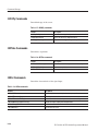
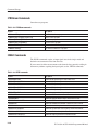
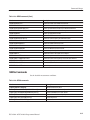
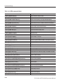
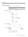
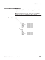
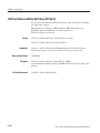
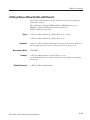
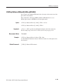
:DISPlay Commands
Control how to show measurement data on the screen.
Table 2-14: :DISPlay commands
Header
Description
:DISPlay:CCDF subgroup
CCDF measurement related.
:DISPlay:CCDF:LINE:GAUSsian[:STATe](?)
Determines whether to show the Gaussian line.
:DISPlay:CCDF:LINE:REFerence[:STATe](?)
Determines whether to show the reference line.
:DISPlay:CCDF:LINE:REFerence:STORe
Stores the current CCDF trace as the reference line.
:DISPlay:CCDF:X[:SCALe]:AUTO(?)
Determines whether to set the horizontal scale automatically.
:DISPlay:CCDF:X[:SCALe]:MAXimum(?)
Sets the maximum horizontal value (right end).
:DISPlay:CCDF:X[:SCALe]:OFFSet(?)
Sets the minimum horizontal value (left end).
:DISPlay:CCDF:Y[:SCALe]:FIT
Runs autoĆscale.
:DISPlay:CCDF:Y[:SCALe]:FULL
Sets the vertical axis to the default fullĆscale.
:DISPlay:CCDF:Y[:SCALe]:MAXimum(?)
Sets the maximum vertical value (top end).
:DISPlay:CCDF:Y[:SCALe]:MINimum(?)
Sets the minimum vertical value (bottom end).
:DISPlay:DDEMod subgroup
Digital modulation analysis related.
:DISPlay:DDEMod:CCDF:LINE:GAUSsian[:STATe](?)
Determines whether to display the Gaussian line.
:DISPlay:DDEMod:MVIew:DSTart(?)
Selects the decoding start position for ASK, FSK, and GFSK signals.
:DISPlay:DDEMod:MVIew:FORMat(?)
Selects the main view display format.
:DISPlay:DDEMod:MVIew:HSSHift(?)
Selects the Q data half symbol shift for an OQPSK signal.
:DISPlay:DDEMod:MVIew:RADix(?)
Selects the base of symbols in the main view.
:DISPlay:DDEMod:MVIew:X[:SCALe]:OFFSet(?)
Sets the minimum horizontal value (left edge) in the main view.
:DISPlay:DDEMod:MVIew:X[:SCALe]:RANGe(?)
Sets the horizontal fullĆscale in the main view.
WCA230A & WCA280A Programmer Manual
2-19
Command Groups
Table 2-14: :DISPlay commands (Cont.)
Header
Description
:DISPlay:DDEMod:MVIew:Y[:SCALe]:FIT
Runs autoĆscale on the main view.
:DISPlay:DDEMod:MVIew:Y[:SCALe]:FULL
Sets the main view's vertical axis to the default fullĆscale value.
:DISPlay:DDEMod:MVIew:Y[:SCALe]:MAXimum(?)
Sets the maximum vertical value (top end) in the CCDF main view.
:DISPlay:DDEMod:MVIew:Y[:SCALe]:MINimum(?)
Sets the minimum vertical value (top end) in the CCDF main view.
:DISPlay:DDEMod:MVIew:Y[:SCALe]:OFFSet(?)
Sets the minimum vertical value (bottom) in the main view.
:DISPlay:DDEMod:MVIew:Y[:SCALe]:RANGe(?)
Sets the vertical fullĆscale in the main view.
:DISPlay:DDEMod:NLINearity:LINE:BFIT[:STATe](?)
Determines whether to display the best-fit line.
:DISPlay:DDEMod:NLINearity:LINE:REFerence[:STATe](?)
Determines whether to display the recovered reference line.
:DISPlay:DDEMod:NLINearity:MASK[:STATe](?)
Determines whether the linear signal region is visible.
:DISPlay:DDEMod:SVIew:DSTart(?)
Selects the decoding start position for ASK, FSK, and GFSK signals.
:DISPlay:DDEMod:SVIew:FORMat(?)
Selects the subview display format.
:DISPlay:DDEMod:SVIew:HSSHift(?)
Selects the Q data half symbol shift for an OQPSK signal.
:DISPlay:DDEMod:SVIew:RADix(?)
Selects the base of symbols in the subview.
:DISPlay:DDEMod:SVIew:X[:SCALe]:OFFSet(?)
Sets the minimum horizontal value (left edge) in the subview.
:DISPlay:DDEMod:SVIew:X[:SCALe]:RANGe(?)
Sets the horizontal fullĆscale in the subview.
:DISPlay:DDEMod:SVIew:Y[:SCALe]:FIT
Runs autoĆscale on the subview.
:DISPlay:DDEMod:SVIew:Y[:SCALe]:FULL
Sets the vertical axis to the default fullĆscale value in the subview.
:DISPlay:DDEMod:SVIew:Y[:SCALe]:MAXimum(?)
Sets the maximum vertical value (top end) in the CCDF subview.
:DISPlay:DDEMod:SVIew:Y[:SCALe]:MINimum(?)
Sets the minimum vertical value (top end) in the CCDF subview.
:DISPlay:DDEMod:SVIew:Y[:SCALe]:OFFSet(?)
Sets the minimum vertical value (bottom) in the subview.
:DISPlay:DDEMod:SVIew:Y[:SCALe]:RANGe(?)
Sets the vertical fullĆscale in the subview.
:DISPlay:OVIew subgroup
DEMOD and TIME mode overview related.
:DISPlay:OVIew:FORMat(?)
Selects the overview display format.
:DISPlay:OVIew:OTINdicator(?)
Determines whether to show the trigger output indicator.
:DISPlay:OVIew:SGRam:COLor[:SCALe]:OFFSet(?)
Sets the minimum colorĆaxis value (bottom end) of the spectrogram.
:DISPlay:OVIew:SGRam:COLor[:SCALe]:RANGe(?)
Sets the colorĆaxis fullĆscale of the spectrogram.
:DISPlay:OVIew:SGRam:X[:SCALe]:OFFSet(?)
Sets the minimum horizontal value (left end) of the spectrogram.
:DISPlay:OVIew:SGRam:X[:SCALe]:SPAN(?)
Sets the horizontal fullĆscale (span) of the spectrogram.
:DISPlay:OVIew:SGRam:Y[:SCALe]:OFFSet(?)
Sets the minimum vertical value of the spectrogram (bottom end).
:DISPlay:OVIew:SGRam:Y[:SCALe]:PLINe(?)
Sets the vertical scale of the spectrogram.
:DISPlay:OVIew:WAVeform:X[:SCALe]:OFFSet(?)
Sets the minimum horizontal value (left edge) in the time domain display.
:DISPlay:OVIew:WAVeform:X[:SCALe]:PDIVision(?)
Sets the horizontal scale in the time domain display.
:DISPlay:OVIew:WAVeform:Y[:SCALe]:FIT
Runs autoĆscale on the time domain display.
:DISPlay:OVIew:WAVeform:Y[:SCALe]:FULL
Sets the time domain display's vertical axis to the default fullĆscale.
2-20
WCA230A & WCA280A Programmer Manual
Command Groups
Table 2-14: :DISPlay commands (Cont.)
Header
Description
:DISPlay:OVIew:WAVeform:Y[:SCALe]:OFFSet(?)
Sets the minimum vertical value in the time domain display.
:DISPlay:OVIew:WAVeform:Y[:SCALe]:PDIVision(?)
Sets the vertical scale in the time domain display.
:DISPlay:OVIew:ZOOM:COLor[:SCALe]:OFFSet(?)
Sets the minimum colorĆaxis value of the spectrogram with zoom.
:DISPlay:OVIew:ZOOM:COLor[:SCALe]:RANGe(?)
Sets the colorĆaxis fullĆscale of the spectrogram with zoom.
:DISPlay:OVIew:ZOOM:X[:SCALe]:OFFSet(?)
Sets the minimum horizontal value of the spectrogram with zoom.
:DISPlay:OVIew:ZOOM:X[:SCALe]:SPAN(?)
Sets the horizontal fullĆscale of the spectrogram with zoom.
:DISPlay:OVIew:ZOOM:Y[:SCALe]:OFFSet(?)
Sets the minimum vertical value of the spectrogram with zoom.
:DISPlay:OVIew:ZOOM:Y[:SCALe]:PLINe(?)
Sets the vertical scale of the spectrogram with zoom.
:DISPlay:PULSe:MVIew|:SVIew subgroup
The main view and subview related in the pulse measurements
:DISPlay:PULSe:MVIew:RESult:CHPower(?)
Determines whether to show channel power measurement results.
:DISPlay:PULSe:MVIew:RESult:DCYCle(?)
Determines whether to show duty cycle measurement results.
:DISPlay:PULSe:MVIew:RESult:EBWidth(?)
Determines whether to show EBW measurement results.
:DISPlay:PULSe:MVIew:RESult:FREQuency(?)
Determines whether to show frequency deviation measurement results.
:DISPlay:PULSe:MVIew:RESult:OBWidth(?)
Determines whether to show OBW measurement results.
:DISPlay:PULSe:MVIew:RESult:OORatio(?)
Determines whether to show on/offĆratio measurement results.
:DISPlay:PULSe:MVIew:RESult:PERiod(?)
Determines whether to show repetition interval measurement results.
:DISPlay:PULSe:MVIew:RESult:PHASe(?)
Determines whether to show pulseĆpulse phase measurement results.
:DISPlay:PULSe:MVIew:RESult:PPOWer(?)
Determines whether to show peak power measurement results.
:DISPlay:PULSe:MVIew:RESult:RIPPle(?)
Determines whether to show pulse ripple measurement results.
:DISPlay:PULSe:MVIew:RESult:WIDTh(?)
Determines whether to show pulse width measurement results.
:DISPlay:PULSe:SVIew:FORMat(?)
Selects the display format of the subview.
:DISPlay:PULSe:SVIew:GUIDelines(?)
Determines whether to show the guidelines in the subview.
:DISPlay:PULSe:SVIew:RANGe(?)
Selects how to set the horizontal scale in the subview.
:DISPlay:PULSe:SVIew:RESult(?)
Selects how to show the result graph in the subview.
:DISPlay:PULSe:SVIew:SELect(?)
Selects a pulse to measure.
:DISPlay:PULSe:SPECtrum subgroup
The spectrum view related in the pulse measurements
:DISPlay:PULSe:SPECtrum:X[:SCALe]:OFFSet(?)
Sets the minimum horizontal value (left edge).
:DISPlay:PULSe:SPECtrum:X[:SCALe]:PDIVision(?)
Sets the horizontal scale (per division).
:DISPlay:PULSe:SPECtrum:Y[:SCALe]:FIT
Runs the autoĆscale.
:DISPlay:PULSe:SPECtrum:Y[:SCALe]:FULL
Sets the vertical axis to the default fullĆscale value.
:DISPlay:PULSe:SPECtrum:Y[:SCALe]:OFFSet(?)
Sets the minimum vertical value (bottom).
:DISPlay:PULSe:SPECtrum:Y[:SCALe]:PDIVision(?)
Sets the vertical scale (per division).
:DISPlay:PULSe:WAVeform subgroup
Time domain display related in the pulse measurements
:DISPlay:PULSe:WAVeform:X[:SCALe]:OFFSet(?)
Sets the minimum value of the horizontal axis (left edge).
:DISPlay:PULSe:WAVeform:X[:SCALe]:PDIVision(?)
Sets or queries the horizontal scale (per division).
WCA230A & WCA280A Programmer Manual
2-21
Command Groups
Table 2-14: :DISPlay commands (Cont.)
Header
Description
:DISPlay:PULSe:WAVeform:Y[:SCALe]:FIT
Runs the autoĆscale.
:DISPlay:PULSe:WAVeform:Y[:SCALe]:FULL
Sets the vertical axis to the default fullĆscale value.
:DISPlay:PULSe:WAVeform:Y[:SCALe]:OFFSet(?)
Sets the minimum value (bottom) of the vertical axis.
:DISPlay:PULSe:WAVeform:Y[:SCALe]:PDIVision(?)
Sets the vertical scale (per division).
:DISPlay:RFID:DDEMod subgroup
Main view and subview related in the RFID analysis.
:DISPlay:RFID:DDEMod:MVIew:BURSt[:NUMBer](?)
Sets the burst number to display the measurement result.
:DISPlay:RFID:DDEMod:MVIew:EDGE[:NUMBer](?)
Sets the edge number to display the measurement result.
:DISPlay:RFID:DDEMod:MVIew:ENVelope[:NUMBer](?)
Sets the envelope number to display the measurement result.
:DISPlay:RFID:DDEMod:MVIew:GUIDeline[:STATe](?)
Determines whether to display the guideline in the main view.
:DISPlay:RFID:DDEMod:MVIew:X[:SCALe]:OFFSet(?)
Sets the minimum horizontal value (left edge) in the main view.
:DISPlay:RFID:DDEMod:MVIew:X[:SCALe]:PDIVision(?)
Sets the horizontal scale (per division) in the main view.
:DISPlay:RFID:DDEMod:MVIew:X[:SCALe]:RANGe(?)
Sets the fullĆscale value of the horizontal axis in the main view.
:DISPlay:RFID:DDEMod:MVIew:Y[:SCALe]:FIT
Runs the autoĆscale on the main view.
:DISPlay:RFID:DDEMod:MVIew:Y[:SCALe]:FULL
Sets the vertical axis in the main view to the default fullĆscale value.
:DISPlay:RFID:DDEMod:MVIew:Y[:SCALe]:OFFSet(?)
Sets the minimum vertical value (bottom) in the main view.
:DISPlay:RFID:DDEMod:MVIew:Y[:SCALe]:PDIVision(?)
Sets the vertical scale (per division) in the main view.
:DISPlay:RFID:DDEMod:MVIew:Y[:SCALe]:RANGe(?)
Sets fullĆscale value of the vertical axis in the main view.
:DISPlay:RFID:DDEMod:SVIew:BURSt[:NUMBer](?)
Sets the burst number to display the measurement result.
:DISPlay:RFID:DDEMod:SVIew:EDGE[:NUMBer](?)
Sets the edge number to display the measurement result.
:DISPlay:RFID:DDEMod:SVIew:ENVelope[:NUMBer](?)
Sets the envelope number to display the measurement result.
:DISPlay:RFID:DDEMod:SVIew:FORMat(?)
Selects the display format of the subview.
:DISPlay:RFID:DDEMod:SVIew:GUIDeline[:STATe](?)
Determines whether to display the guideline in the subview.
:DISPlay:RFID:DDEMod:SVIew:X[:SCALe]:OFFSet(?)
Sets the minimum horizontal value (left edge) in the subview.
:DISPlay:RFID:DDEMod:SVIew:X[:SCALe]:PDIVision(?)
Sets the horizontal scale (time per division) in the subview.
:DISPlay:RFID:DDEMod:SVIew:X[:SCALe]:RANGe(?)
Sets fullĆscale value of the horizontal axis in the subview.
:DISPlay:RFID:DDEMod:SVIew:Y[:SCALe]:FIT
Runs the autoĆscale on the subview.
:DISPlay:RFID:DDEMod:SVIew:Y[:SCALe]:FULL
Sets the vertical axis in the subview to the default fullĆscale value.
:DISPlay:RFID:DDEMod:SVIew:Y[:SCALe]:OFFSet(?)
Sets the minimum vertical value (bottom) in the subview.
:DISPlay:RFID:DDEMod:SVIew:Y[:SCALe]:PDIVision(?)
Sets the vertical scale (per division) in the time domain display.
:DISPlay:RFID:DDEMod:SVIew:Y[:SCALe]:RANGe(?)
Sets fullĆscale value of the vertical axis in the subview.
:DISPlay:RFID:SPECtrum subgroup
Spectrum view related in the RFID analysis.
:DISPlay:RFID:SPECtrum:X[:SCALe]:OFFSet(?)
Sets the minimum horizontal, or frequency, value (left edge).
:DISPlay:RFID:SPECtrum:X[:SCALe]:PDIVision(?)
Sets the horizontal, or frequency, scale (per division).
:DISPlay:RFID:SPECtrum:Y[:SCALe]:FIT
Runs the autoĆscale on the spectrum view.
:DISPlay:RFID:SPECtrum:Y[:SCALe]:FULL
Sets the vertical axis to the default fullĆscale value.
2-22
WCA230A & WCA280A Programmer Manual
Command Groups
Table 2-14: :DISPlay commands (Cont.)
Header
Description
:DISPlay:RFID:SPECtrum:Y[:SCALe]:OFFSet(?)
Sets the minimum vertical, or amplitude, value (bottom).
:DISPlay:RFID:SPECtrum:Y[:SCALe]:PDIVision(?)
Sets the vertical, or amplitude, scale (per division).
:DISPlay:RFID:WAVeform subgroup
Time domain display related in the RFID analysis.
:DISPlay:RFID:WAVeform:X[:SCALe]:OFFSet(?)
Sets the minimum value of the horizontal axis (left edge).
:DISPlay:RFID:WAVeform:X[:SCALe]:PDIVision(?)
Sets the horizontal, or time, scale (per division).
:DISPlay:RFID:WAVeform:Y[:SCALe]:FIT
Runs the autoĆscale on the time domain display.
:DISPlay:RFID:WAVeform:Y[:SCALe]:FULL
Sets the vertical axis to the default fullĆscale value.
:DISPlay:RFID:WAVeform:Y[:SCALe]:OFFSet(?)
Sets the minimum value (bottom) of the vertical axis.
:DISPlay:RFID:WAVeform:Y[:SCALe]:PDIVision(?)
Sets the vertical axis scale (per division).
:DISPlay:SPECtrum subgroup
Spectrum measurement related.
:DISPlay:SPECtrum:BMARker:STATe(?)
Turns on or off the band power marker.
:DISPlay:SPECtrum:GRATicule:GRID(?)
Determines how the graticule is displayed.
:DISPlay:SPECtrum:MLINe:AMPLitude:INTerval(?)
Sets the interval of the amplitude multi display lines.
:DISPlay:SPECtrum:MLINe:AMPLitude:OFFSet(?)
Sets the offset of the amplitude multi display lines.
:DISPlay:SPECtrum:MLINe:AMPLitude[:STATe](?)
Determines whether to show the amplitude multi display lines.
:DISPlay:SPECtrum:MLINe:ANNotation[:STATe](?)
Determines whether to show the readout of the multi display lines.
:DISPlay:SPECtrum:MLINe:FREQuency:INTerval(?)
Sets the interval of the frequency multi display lines.
:DISPlay:SPECtrum:MLINe:FREQuency:OFFSet(?)
Sets the offset of the frequency multi display line.
:DISPlay:SPECtrum:MLINe:FREQuency[:STATe](?)
Determines whether to show the frequency multi display lines.
:DISPlay:SPECtrum:X[:SCALe]:OFFSet(?)
Sets the minimum horizontal value (start frequency).
:DISPlay:SPECtrum:X[:SCALe]:PDIVision(?)
Sets the horizontal scale (span/div).
:DISPlay:SPECtrum:Y[:SCALe]:FIT
Runs autoĆscale.
:DISPlay:SPECtrum:Y[:SCALe]:FULL
Sets the vertical axis to the default fullĆscale.
:DISPlay:SPECtrum:Y[:SCALe]:OFFSet(?)
Sets the minimum vertical, or amplitude, value (bottom end).
:DISPlay:SPECtrum:Y[:SCALe]:PDIVision(?)
Sets the vertical, or amplitude, scale per division.
:DISPlay:SSOurce:MVIew subgroup
Main view related in the signal source analysis.
:DISPlay:SSOurce:MVIew:X[:SCALe]:OFFSet(?)
Sets the minimum horizontal value (left edge) in the main view.
:DISPlay:SSOurce:MVIew:X[:SCALe]:PDIVision(?)
Sets the horizontal scale (per division) in the main view.
:DISPlay:SSOurce:MVIew:X[:SCALe]:RANGe(?)
Sets the fullĆscale value of the horizontal axis in the main view.
:DISPlay:SSOurce:MVIew:X[:SCALe]:STARt(?)
Sets the minimum horizontal value (left edge) in the main view.
:DISPlay:SSOurce:MVIew:X[:SCALe]:STOP(?)
Sets the maximum horizontal value (right edge) in the main view.
:DISPlay:SSOurce:MVIew:Y[:SCALe]:FIT
Runs the autoĆscale on the main view.
:DISPlay:SSOurce:MVIew:Y[:SCALe]:FULL
Sets the vertical axis in the main view to the default fullĆscale value.
:DISPlay:SSOurce:MVIew:Y[:SCALe]:OFFSet(?)
Sets the minimum vertical value (bottom) in the main view.
WCA230A & WCA280A Programmer Manual
2-23
Command Groups
Table 2-14: :DISPlay commands (Cont.)
Header
Description
:DISPlay:SSOurce:MVIew:Y[:SCALe]:PDIVision(?)
Sets the vertical scale (per division) in the main view.
:DISPlay:SSOurce:MVIew:Y[:SCALe]:RANGe(?)
Sets fullĆscale value of the vertical axis in the main view.
:DISPlay:SSOurce:SVIew subgroup
Subview related in the signal source analysis.
:DISPlay:SSOurce:SVIew:COLor[:SCALe]:OFFSet(?)
Sets the minimum value (bottom) of the color axis in the subview.
:DISPlay:SSOurce:SVIew:COLor[:SCALe]:RANGe(?)
Sets fullĆscale value of the color axis in the subview.
:DISPlay:SSOurce:SVIew:FORMat(?)
Selects the display format of the subview.
:DISPlay:SSOurce:SVIew:X[:SCALe]:OFFSet(?)
Sets the minimum horizontal value (left edge) in the subview.
:DISPlay:SSOurce:SVIew:X[:SCALe]:PDIVision(?)
Sets the horizontal scale (per division) in the subview.
:DISPlay:SSOurce:SVIew:X[:SCALe]:RANGe(?)
Sets the fullĆscale value of the horizontal axis in the subview.
:DISPlay:SSOurce:SVIew:X[:SCALe]:STARt(?)
Sets the minimum horizontal value (left edge) in the subview.
:DISPlay:SSOurce:SVIew:X[:SCALe]:STOP(?)
Sets the maximum horizontal value (right edge) in the subview.
:DISPlay:SSOurce:SVIew:Y[:SCALe]:FIT
Runs the autoĆscale on the subview.
:DISPlay:SSOurce:SVIew:Y[:SCALe]:FULL
Sets the vertical axis in the subview to the default fullĆscale value.
:DISPlay:SSOurce:SVIew:Y[:SCALe]:OFFSet(?)
Sets the minimum vertical value (bottom) in the subview.
:DISPlay:SSOurce:SVIew:Y[:SCALe]:PDIVision(?)
Sets the vertical scale (per division) in the subview.
:DISPlay:SSOurce:SVIew:Y[:SCALe]:PLINe(?)
Sets the vertical scale (the number of frames per line) in the subview.
:DISPlay:SSOurce:SVIew:Y[:SCALe]:RANGe(?)
Sets fullĆscale value of the vertical axis in the subview.
:DISPlay:SSOurce:SPECtrum subgroup
Spectrum display related in the Signal source analysis.
:DISPlay:SSOurce:SPECtrum:X[:SCALe]:OFFSet(?)
Sets the minimum horizontal, or frequency, value (left edge).
:DISPlay:SSOurce:SPECtrum:X[:SCALe]:PDIVision(?)
Sets the horizontal, or frequency, scale (per division).
:DISPlay:SSOurce:SPECtrum:Y[:SCALe]:FIT
Runs the autoĆscale on the spectrum view.
:DISPlay:SSOurce:SPECtrum:Y[:SCALe]:FULL
Sets the vertical axis to the default fullĆscale value in the spectrum view.
:DISPlay:SSOurce:SPECtrum:Y[:SCALe]:OFFSet(?)
Sets the minimum vertical, or amplitude, value (bottom).
:DISPlay:SSOurce:SPECtrum:Y[:SCALe]:PDIVision(?)
Sets the vertical, or amplitude, scale (per division).
:DISPlay:SSOurce:TFRequency subgroup
ThreeĆdimensional view related in the signal source analysis.
:DISPlay:SSOurce:TFRequency:NGRam:COLor[:SCALe]
:OFFSet(?)
Sets the minimum value (bottom) of the color, or C/N, axis.
:DISPlay:SSOurce:TFRequency:NGRam:COLor[:SCALe]
:RANGe(?)
Sets fullĆscale value of the color, or C/N, axis.
:DISPlay:SSOurce:TFRequency:NGRam:X[:SCALe]
:STARt(?)
Sets the minimum horizontal, or frequency, value (left edge).
:DISPlay:SSOurce:TFRequency:NGRam:X[:SCALe]:
STOP(?)
Sets the maximum horizontal, or frequency, value (right edge).
2-24
WCA230A & WCA280A Programmer Manual
Command Groups
Table 2-14: :DISPlay commands (Cont.)
Header
Description
:DISPlay:SSOurce:TFRequency:NGRam:Y[:SCALe]
:OFFSet(?)
Sets the minimum vertical, or frame number, value (bottom).
:DISPlay:SSOurce:TFRequency:NGRam:Y[:SCALe]
:PLINe(?)
Sets the vertical scale (the number of frames per line).
:DISPlay:SSOurce:WAVeform subgroup
Time domain display related in the signal source analysis.
:DISPlay:SSOurce:WAVeform:X[:SCALe]:OFFSet(?)
Sets the minimum value of the horizontal axis (left edge).
:DISPlay:SSOurce:WAVeform:X[:SCALe]:PDIVision(?)
Sets the horizontal, or time, scale (per division).
:DISPlay:SSOurce:WAVeform:Y[:SCALe]:FIT
Runs the autoĆscale on the time domain display.
:DISPlay:SSOurce:WAVeform:Y[:SCALe]:FULL
Sets the vertical axis to the default fullĆscale value.
:DISPlay:SSOurce:WAVeform:Y[:SCALe]:OFFSet(?)
Sets the minimum value (bottom) of the vertical axis.
:DISPlay:SSOurce:WAVeform:Y[:SCALe]:PDIVision(?)
Sets the vertical axis scale (per division).
:DISPlay:TFRequency subgroup
3Ćdimensional view related.
:DISPlay:TFRequency:SGRam:COLor[:SCALe]:OFFSet(?)
Sets the minimum colorĆaxis value (bottom end) of the spectrogram.
:DISPlay:TFRequency:SGRam:COLor[:SCALe]:RANGe(?)
Sets the scale of the spectrogram's color axis.
:DISPlay:TFRequency:SGRam:MLINe:ANNotation[:STATe]
(?)
Determines whether to show the readout of the multi display lines.
:DISPlay:TFRequency:SGRam:MLINe:FREQuency:INTerval
(?)
Sets the interval of the frequency multi display lines.
:DISPlay:TFRequency:SGRam:MLINe:FREQuency:OFFSet
(?)
Sets the offset of the frequency multi display lines.
:DISPlay:TFRequency:SGRam:MLINe:FREQuency[:STATe]
(?)
Determines whether to show the frequency multi display lines.
:DISPlay:TFRequency:SGRam:MLINe:TIME:INTerval(?)
Sets the interval of the time multi display lines.
:DISPlay:TFRequency:SGRam:MLINe:TIME:OFFSet(?)
Sets the offset of the time multi display lines.
:DISPlay:TFRequency:SGRam:MLINe:TIME[:STATe](?)
Determines whether to show the time multi display lines.
:DISPlay:TFRequency:SGRam:X[:SCALe]:OFFSet(?)
Sets the minimum horizontal value (left end) of the spectrogram.
:DISPlay:TFRequency:SGRam:X[:SCALe]:SPAN(?)
Sets the horizontal fullĆscale (span) of the spectrogram.
:DISPlay:TFRequency:SGRam:Y[:SCALe]:OFFSet(?)
Sets the minimum vertical value (bottom end) of the spectrogram.
:DISPlay:TFRequency:SGRam:Y[:SCALe]:PLINe(?)
Sets the vertical scale of the spectrogram.
:DISPlay[:VIEW] subgroup
General conditions about display.
:DISPlay[:VIEW]:BRIGhtness(?)
Sets the display brightness.
:DISPlay[:VIEW]:FORMat(?)
Selects the view display format.
:DISPlay:WAVeform subgroup
Time domain display related.
:DISPlay:WAVeform:X[:SCALe]:OFFSet(?)
Sets the minimum horizontal, or time, value (left end).
:DISPlay:WAVeform:X[:SCALe]:PDIVision(?)
Sets the horizontal, or time, scale per division.
WCA230A & WCA280A Programmer Manual
2-25
Command Groups
Table 2-14: :DISPlay commands (Cont.)
Header
Description
:DISPlay:WAVeform:Y[:SCALe]:FIT
Runs autoĆscale.
:DISPlay:WAVeform:Y[:SCALe]:FULL
Sets the vertical axis to the default fullĆscale.
:DISPlay:WAVeform:Y[:SCALe]:OFFSet(?)
Sets the minimum vertical, or amplitude, value (bottom end).
:DISPlay:WAVeform:Y[:SCALe]:PDIVision(?)
Sets the vertical, or amplitude, scale.
:FETCh Commands
The :FETCh commands retrieve the measurements from the data taken by the
latest INITiate command.
If you want to perform a FETCh operation on fresh data, use the :READ
commands, which acquire a new input signal and fetch the measurement results
from that data.
Table 2-15: :FETCh commands
Header
Description
:FETCh:ADEMod:AM?
Returns the AM signal analysis results in time series.
:FETCh:ADEMod:AM:RESult?
Returns the AM signal analysis results.
:FETCh:ADEMod:FM?
Returns the FM signal analysis results in time series.
:FETCh:ADEMod:FM:RESult?
Returns the FM signal analysis results.
:FETCh:ADEMod:PM?
Returns the PM signal analysis results in time series.
:FETCh:ADEMod:PSPectrum?
Returns the spectrum data of the pulse spectrum measurement.
:FETCh:CCDF?
Returns the CCDF measurement results.
:FETCh:DDEMod?
Returns the digital modulation analysis measurement results.
:FETCh:DISTribution:CCDF?
Returns the CCDF trace data.
:FETCh:OVIew?
Returns the maximum and minimum of waveform on the overview.
:FETCh:PULSe?
Returns the result of the pulse characteristics analysis.
:FETCh:PULSe:SPECtrum?
Returns the spectrum data of the frequency domain measurement.
:FETCh:PULSe:TAMPlitude?
Returns the time domain amplitude data.
:FETCh:PULSe:TFRequency?
Returns the frequency deviation measurement results.
:FETCh:RFID?
Returns the measurement result of the RFID analysis.
:FETCh:RFID:ACPower?
Returns the results of the ACPR measurement.
:FETCh:RFID:SPURious?
Returns the results of the spurious signal measurement.
:FETCh:RFID:SPECtrum:ACPower?
Returns spectrum waveform data of the ACPR measurement.
:FETCh:RFID:SPECtrum:SPURious?
Returns spectrum waveform data of the spurious measurement.
2-26
WCA230A & WCA280A Programmer Manual
Command Groups
Table 2-15: :FETCh commands (Cont.)
Header
Description
:FETCh:SPECtrum?
Returns spectrum waveform data.
:FETCh:SPECtrum:ACPower?
Returns the ACPR measurement results.
:FETCh:SPECtrum:CFRequency?
Returns the carrier frequency measurement results.
:FETCh:SPECtrum:CHPower?
Returns the channel power measurement results.
:FETCh:SPECtrum:CNRatio?
Returns the C/N measurement results.
:FETCh:SPECtrum:EBWidth?
Returns the emission bandwidth measurement results.
:FETCh:SPECtrum:OBWidth?
Returns the OBW measurement results.
:FETCh:SPECtrum:SPURious?
Returns the spurious signal measurement results.
:FETCh:SSOurce?
Returns the measurement result in the signal source analysis.
:FETCh:SSOurce:CNVFrequency?
Returns measurement data of the C/N versus offset frequency.
:FETCh:SSOurce:CNVTime?
Returns waveform data of the C/N versus time.
:FETCh:SSOurce:IPNVtime?
Returns waveform data of the integrated phase noise versus time.
:FETCh:SSOurce:RJVTime?
Returns waveform data of the random jitter versus time.
:FETCh:SSOurce:SPECtrum?
Returns the spectrum data.
:FETCh:SSOurce:TRANsient:FVTime?
Returns the frequency versus time measurement. results.
:FETCh:TRANsient:FVTime?
Returns the frequency vs. time measurement results.
:FETCh:TRANsient:IQVTime?
Returns the I/Q level vs. time measurement results.
:FETCh:TRANsient:PVTime?
Returns the power vs. time measurement results.
:FORMat Commands
Define the data output format.
Table 2-16: :FORMat commands
Header
Description
:FORMat:BORDer(?)
Selects the byte order of output data.
:FORMat[:DATA](?)
Selects the data format for output.
WCA230A & WCA280A Programmer Manual
2-27
Command Groups
:HCOPy Commands
Control hardcopy of the screen.
Table 2-17: :HCOPy commands
Header
Description
:HCOPy:BACKground
Selects the hardcopy background color.
:HCOPy:DESTination
Selects the hardcopy output destination.
:HCOPy[:IMMediate]
Outputs the hardcopy to the specified printer.
:INITiate Commands
Control data acquisition.
Table 2-18: :INITiate commands
Header
Description
:INITiate:CONTinuous(?)
Determines whether to acquire data continuously.
:INITiate[:IMMediate]
Starts data acquisition.
:INITiate:RESTart
Restarts data acquisition.
:INPut Commands
Control the characteristics of the signal input.
Table 2-19: :INPut commands
Header
Description
:INPut:ALEVel
Adjusts amplitude automatically for the best system performance.
:INPut:ATTenuation(?)
Sets the input attenuation.
:INPut:ATTenuation:AUTO(?)
Determines whether to set the input attenuation automatically.
:INPut:COUPling(?) (Option 03 only)
Switches the input coupling in the IQ input mode.
:INPut:MIXer(?)
Sets the mixer level.
:INPut:MLEVel(?)
Sets the reference level.
2-28
WCA230A & WCA280A Programmer Manual
Command Groups
:INSTrument Commands
Sets the measurement mode for the analyzer.
Table 2-20: :INSTrument commands
Header
Description
:INSTrument:CATalog?
Queries all the measurement modes that the analyzer has.
:INSTrument[:SELect]
Selects the measurement mode.
:MMEMory Commands
Manipulates files residing on the internal hard disk or floppy disk.
Table 2-21: :MMEMory commands
Header
Description
:MMEMory:COPY
Copies the contents of a file to another.
:MMEMory:DELete
Deletes a file.
:MMEMory:LOAD:CORRection
Loads the correction table from a file.
:MMEMory:LOAD:IQT
Loads the IQ data from a file.
:MMEMory:LOAD:STATe
Loads the analyzer settings from a file.
:MMEMory:LOAD:TRACe
Loads trace data from a file.
:MMEMory:NAME
Specifies the file name for hard copy output.
:MMEMory:STORe:ACPower
Stores the ACPR measurement results in a file in the RFID analysis.
:MMEMory:STORe:CORRection
Stores an amplitude correction table in a file.
:MMEMory:STORe:IQT
Stores IQ data in a file.
:MMEMory:STORe:PULSe
Stores the pulse measurement results in a file.
:MMEMory:STORe:STABle
Stores a symbol table in a file.
:MMEMory:STORe:STATe
Stores the analyzer settings in a file.
:MMEMory:STORe:TRACe
Stores trace data in a file.
WCA230A & WCA280A Programmer Manual
2-29
Command Groups
:PROGram Commands
Control macro programs.
Table 2-22: :PROGram commands
Header
Description
:PROGram:CATalog?
Queries the list of macro programs.
:PROGram[:SELected]:DELete[:SELected]
Deletes a macro program.
:PROGram[:SELected]:EXECute
Runs a macro program.
:PROGram[:SELected]:NAME(?)
Specifies a macro program.
:PROGram:NUMBer(?)
Sets numeric variables for a program.
:PROGram:STRing(?)
Sets character variables for a program.
:READ Commands
The :READ commands acquire an input signal once in the single mode and
obtain the measurement results from that data.
If you want to fetch the measurement results from the data currently residing in
the memory without acquiring the input signal, use the :FETCh commands.
Table 2-23: :READ commands
Header
Description
:READ:ADEMod:AM?
Returns the AM signal analysis results in time series.
:READ:ADEMod:AM:RESult?
Returns the AM signal analysis results.
:READ:ADEMod:FM?
Returns the FM signal analysis results in time series.
:READ:ADEMod:FM:RESult?
Returns the FM signal analysis results.
:READ:ADEMod:PM?
Returns the PM signal analysis results in time series.
:READ:ADEMod:PSPectrum?
Returns the spectrum data of the pulse spectrum measurement.
:READ:CCDF?
Returns the CCDF measurement results.
:READ:DDEMod?
Returns the digital modulation analysis measurement results.
:READ:DISTribution:CCDF?
Returns the CCDF trace data.
:READ:OVIew?
Returns the maximum and minimum of waveform on the overview.
:READ:PULSe?
Returns the result of the pulse characteristics analysis.
:READ:PULSe:SPECtrum?
Returns the spectrum data of the frequency domain measurement.
:READ:PULSe:TAMPlitude?
Returns the time domain amplitude data.
:READ:PULSe:TFRequency?
Returns the frequency deviation measurement results.
2-30
WCA230A & WCA280A Programmer Manual
Command Groups
Table 2-23: :READ commands (Cont.)
Header
Description
:READ:RFID:ACPower?
Returns the results of the ACPR measurement.
:READ:RFID:SPURious?
Returns the results of the spurious signal measurement.
:READ:RFID:SPECtrum:ACPower?
Returns spectrum waveform data of the ACPR measurement.
:READ:RFID:SPECtrum:SPURious?
Returns spectrum waveform data of the spurious measurement.
:READ:SPECtrum?
Returns spectrum waveform data.
:READ:SPECtrum:ACPower?
Returns the ACPR measurement results.
:READ:SPECtrum:CFRequency?
Returns the carrier frequency measurement results.
:READ:SPECtrum:CHPower?
Returns the channel power measurement results.
:READ:SPECtrum:CNRatio?
Returns the C/N measurement results.
:READ:SPECtrum:EBWidth?
Returns the emission bandwidth measurement results.
:READ:SPECtrum:OBWidth?
Returns the OBW measurement results.
:READ:SPECtrum:SPURious?
Returns the spurious signal measurement results.
:READ:SSOurce?
Returns the results of the signal source analysis.
:READ:SSOurce:SPECtrum?
Returns the spectrum data.
:READ:SSOurce:TRANsient:FVTime?
Returns the results of the frequency versus time measurement.
:READ:TRANsient:FVTime?
Returns the frequency vs. time measurement results.
:READ:TRANsient:IQVTime?
Returns the I/Q level vs. time measurement results.
:READ:TRANsient:PVTime?
Returns the power vs. time measurement results.
:SENSe Commands
Set the detailed measurement conditions.
Table 2-24: :SENSe commands
Header
Description
[:SENSe]:ACPower subgroup
ACPR measurement related.
[:SENSe]:ACPower:BANDwidth|BWIDth:ACHannel(?)
Sets the bandwidth of the next adjacent channel.
[:SENSe]:ACPower:BANDwidth|BWIDth:INTegration(?)
Sets the bandwidth of the main channel.
[:SENSe]:ACPower:CSPacing(?)
Sets the channelĆtoĆchannel spacing.
[:SENSe]:ACPower:FILTer:COEFficient(?)
Sets the filter factor.
[:SENSe]:ACPower:FILTer:TYPE(?)
Selects a filter.
WCA230A & WCA280A Programmer Manual
2-31
Command Groups
Table 2-24: :SENSe commands (Cont.)
Header
Description
[:SENSe]:ADEMod subgroup
Analog modulation analysis related.
[:SENSe]:ADEMod:BLOCk(?)
Sets the number of the block to be measured.
[:SENSe]:ADEMod:CARRier:OFFSet(?)
Sets the carrier frequency offset in the FM signal analysis.
[:SENSe]:ADEMod:CARRier:SEARch(?)
Determines whether to detect the FM carrier automatically.
[:SENSe]:ADEMod:FM:THReshold(?)
Sets the threshold level to determine a burst in the FM analysis.
[:SENSe]:ADEMod[:IMMediate]
Runs the analog modulation analysis.
[:SENSe]:ADEMod:LENGth(?)
Sets the length of the measurement range.
[:SENSe]:ADEMod:MODulation(?)
Selects the modulation.
[:SENSe]:ADEMod:OFFSet(?)
Sets the measurement start position.
[:SENSe]:ADEMod:PM:THReshold(?)
Sets the threshold level to determine a burst in the PM analysis.
[:SENSe]:AVERage subgroup
Averaging related.
[:SENSe]:AVERage:CLEar
Restarts the averaging from the beginning.
[:SENSe]:AVERage:COUNt(?)
Sets the number of averages.
[:SENSe]:AVERage[:STATe](?)
Turns on or off averaging.
[:SENSe]:AVERage:TCONtrol(?)
Selects the operation when the number of averages is reached.
[:SENSe]:BSIZe subgroup
Block size setting.
[:SENSe]:BSIZe(?)
Sets the block size.
CCDF subgroup
CCDF measurement related.
[:SENSe]:CCDF:BLOCk(?)
Sets the number of the block to be measured.
[:SENSe]:CCDF:CLEar
Restarts the measurement from the beginning.
[:SENSe]:CCDF:RMEasurement(?)
Clears the CCDF accumulator and restarts the measurement..
[:SENSe]:CCDF:THReshold(?)
Sets the threshold to include the samples in the CCDF calculation.
[:SENSe]:CFRequency subgroup
Carrier frequency measurement related.
[:SENSe]:CFRequency:CRESolution(?)
Sets the counter resolution.
[:SENSe]:CHPower subgroup
Channel power measurement related.
[:SENSe]:CHPower:BANDwidth|BWIDth:INTegration(?)
Sets the channel bandwidth.
[:SENSe]:CHPower:FILTer:COEFficient(?)
Sets the filter rollĆoff rate.
[:SENSe]:CHPower:FILTer:TYPE(?)
Selects the filter.
[:SENSe]:CNRatio subgroup
CarrierĆtoĆNoise (C/N) measurement related.
[:SENSe]:CNRatio:BANDwidth|BWIDth:INTegration(?)
Sets the measurement bandwidth.
[:SENSe]:CNRatio:BANDwidth|BWIDth:NOISe(?)
Sets the noise bandwidth.
[:SENSe]:CNRatio:FILTer:COEFficient(?)
Sets the filter rollĆoff rate.
[:SENSe]:CNRatio:FILTer:TYPE(?)
Selects the filter.
[:SENSe]:CNRatio:OFFSet(?)
Sets the offset frequency.
[:SENSe]:CORRection subgroup
Amplitude correction related.
2-32
WCA230A & WCA280A Programmer Manual
Command Groups
Table 2-24: :SENSe commands (Cont.)
Header
Description
[:SENSe]:CORRection:DATA(?)
Sets amplitude correction data.
[:SENSe]:CORRection:DELete
Deletes amplitude correction data.
[:SENSe]:CORRection:OFFSet[:MAGNitude](?)
Sets amplitude offset.
[:SENSe]:CORRection:OFFSet:FREQuency(?)
Sets frequency offset.
[:SENSe]:CORRection[:STATe](?)
Turns on or off amplitude correction.
[:SENSe]:CORRection:X:SPACing(?)
Selects scaling of the horizontal axis (frequency) for interpolation.
[:SENSe]:CORRection:Y:SPACing(?)
Selects scaling of the vertical axis (amplitude) for interpolation.
[:SENSe]:DDEMod subgroup
Digital modulation analysis related.
[:SENSe]:DDEMod:BLOCk(?)
Sets the number of the block to be measured.
[:SENSe]:DDEMod:CARRier:OFFSet(?)
Sets the carrier frequency offset.
[:SENSe]:DDEMod:CARRier:SEARch(?)
Determines whether to detect the carrier automatically.
[:SENSe]:DDEMod:DECode(?)
Selects the method that is used to decode the data bits.
[:SENSe]:DDEMod:FDEViation(?)
Sets the frequency deviation to determine two states for FSK.
[:SENSe]:DDEMod:FDEViation:AUTO(?)
Selects whether to detect the frequency deviation automatically.
[:SENSe]:DDEMod:FILTer:ALPHa(?)
Sets the filter factor (a/BT).
[:SENSe]:DDEMod:FILTer:MEASurement(?)
Selects the measurement filter.
[:SENSe]:DDEMod:FILTer:REFerence(?)
Selects the reference filter.
[:SENSe]:DDEMod:FORMat(?)
Selects the modulation.
[:SENSe]:DDEMod[:IMMediate]
Starts the digital modulation calculation.
[:SENSe]:DDEMod:LENGth(?)
Sets the measurement range.
[:SENSe]:DDEMod:MDEPth(?)
Sets the modulation depth to separate two states in ASK.
[:SENSe]:DDEMod:MDEPth:AUTO(?)
Determines whether to detect the modulation depth automatically.
[:SENSe]:DDEMod:NLINearity:COEFficient(?)
Sets the maximum order of the bestĆfit curve polynomial.
[:SENSe]:DDEMod:NLINearity:HDIVision(?)
Sets the horizontal interval between display points.
[:SENSe]:DDEMod:NLINearity:LSRegion[:SET](?)
Sets the linear signal region.
[:SENSe]:DDEMod:NLINearity:LSRegion:UNIT(?)
Selects the unit to set the liner signal region.
[:SENSe]:DDEMod:OFFSet(?)
Sets the measurement start position.
[:SENSe]:DDEMod:PRESet(?)
Sets the default settings by the communication standard.
[:SENSe]:DDEMod:SRATe(?)
Sets the symbol rate.
[:SENSe]:EBWidth subgroup
EBW measurement related.
[:SENSe]:EBWidth:XDB(?)
Sets the relative power from the peak for the measurement.
[:SENSe]:FEED subgroup
Input port related.
[:SENSe]:FEED
Selects the input port (RF, IQ, or calibration signal).
WCA230A & WCA280A Programmer Manual
2-33
Command Groups
Table 2-24: :SENSe commands (Cont.)
Header
Description
[:SENSe]:FREQuency subgroup
Frequency related.
[:SENSe]:FREQuency:BAND?
Queries the measurement frequency band.
[:SENSe]:FREQuency:CENTer(?)
Sets the center frequency.
[:SENSe]:FREQuency:CENTer:STEP:AUTO(?)
Determines whether to set the step size automatically by span.
[:SENSe]:FREQuency:CENTer:STEP[:INCRement](?)
Sets the step size of the center frequency.
[:SENSe]:FREQuency:CHANnel(?)
Selects a channel.
[:SENSe]:FREQuency:CTABle:CATalog?
Queries the available channel tables.
[:SENSe]:FREQuency:CTABle[:SELect](?)
Selects a channel table.
[:SENSe]:FREQuency:SPAN(?)
Sets the span.
[:SENSe]:FREQuency:STARt(?)
Sets the start frequency.
[:SENSe]:FREQuency:STOP(?)
Sets the stop frequency.
[:SENSe]:OBWidth subgroup
OBW measurement related.
[:SENSe]:OBWidth:PERCent(?)
Sets the occupied bandwidth.
[:SENSe]:PULSe subgroup
Pulse characteristics analysis related
[:SENSe]:PULSe:BLOCk(?)
Sets the number of the block to measure.
[:SENSe]:PULSe:CHPower:BANDwidth|:BWIDth:INTegration(?)
Sets the channel bandwidth for the channel power measurement.
[:SENSe]:PULSe:CRESolution(?)
Sets the frequency measurement resolution.
[:SENSe]:PULSe:EBWidth:XDB(?)
Sets the level at which the EBW is measured.
[:SENSe]:PULSe:FFT:COEFficient(?)
Sets the rollĆoff ratio for the Nyquist FFT window.
[:SENSe]:PULSe:FFT:WINDow[:TYPE](?)
Selects the FFT window type.
[:SENSe]:PULSe:FILTer:BANDwidth|BWIDth(?)
Sets the bandwidth of the time measurement filter.
[:SENSe]:PULSe:FILTer:COEFficient(?)
Sets the a/BT value for the Gaussian measurement filter.
[:SENSe]:PULSe:FILTer:MEASuerment(?)
Selects the measurement filter for the time measurement.
[:SENSe]:PULSe:FREQuency:OFFSet(?)
Sets the frequency offset.
[:SENSe]:PULSe:FREQuency:RECovery(?)
Selects the frequency recovery.
[:SENSe]:PULSe[:IMMediate](?)
Runs calculation for acquired data.
[:SENSe]:PULSe:OBWidth:PERcent(?)
Sets OBW for the OBW measurement.
[:SENSe]:PULSe:PTOFfset(?)
Sets the time offset for the pulseĆpulse phase measurement point.
[:SENSe]:PULSe:THReshold(?)
Sets the threshold level to detect pulses in acquired data.
[:SENSe]:RFID subgroup
RFID analysis related.
[:SENSe]:RFID:ACPower:BANDwidth|:BWIDth:ACHannel(?)
Sets the adjacent channel bandwidth in the ACPR measurement.
[:SENSe]:RFID:ACPower:BANDwidth|:BWIDth:INTegration(?)
Sets the main channel bandwidth in the ACPR measurement.
[:SENSe]:RFID:ACPower:CSPacing(?)
Sets the channelĆtoĆchannel spacing in the ACPR measurement.
[:SENSe]:RFID:ACPower:FILTer:COEFficient(?)
Sets the filter factor in the ACPR measurement.
[:SENSe]:RFID:ACPower:FILTer:TYPE(?)
Selects the filter for the ACPR measurement.
2-34
WCA230A & WCA280A Programmer Manual
Command Groups
Table 2-24: :SENSe commands (Cont.)
Header
Description
[:SENSe]:RFID:BLOCk(?)
Sets the number of the block to measure.
[:SENSe]:RFID:CARRier:BANDwidth|:BWIDth:INTegration(?)
Sets the channel bandwidth for the maximum EIRP.
[:SENSe]:RFID:CARRier:COUNter[:RESolution](?)
Sets the counter resolution for the carrier measurement.
[:SENSe]:RFID:CARRier:OFFSet(?)
Sets the amplitude offset for the maximum EIRP.
[:SENSe]:RFID:CARRier:PRATio[:SET](?)
Sets the power ratio for the OBW measurement.
[:SENSe]:RFID:CARRier:PRATio:UNIT(?)
Selects the power ratio unit for the OBW measuremen.
[:SENSe]:RFID[:IMMediate]
Perform analysis calculation for the acquired data.
[:SENSe]:RFID:LENGth(?)
Sets the analysis range.
[:SENSe]:RFID:MEASurement(?)
Selects the measurement item.
[:SENSe]:RFID:MODulation:BRATe:AUTO(?)
Determines whether to set the bit rate automatically.
[:SENSe]:RFID:MODulation:BRATe[:SET](?)
Sets the bit rate.
[:SENSe]:RFID:MODulation:DECode(?)
Selects the decoding format.
[:SENSe]:RFID:MODulation:FORMat(?)
Selects the modulation format.
[:SENSe]:RFID:MODulation:INTerpolate(?)
Sets the number of waveform interpolation points.
[:SENSe]:RFID:MODulation:LINK(?)
Selects the link.
[:SENSe]:RFID:MODulation:SERRor[:WIDTh](?)
Sets an error range for determining the settling time.
[:SENSe]:RFID:MODulation:STANdard(?)
Selects the demodulation standard.
[:SENSe]:RFID:MODulation:TARI:AUTO(?)
Determines whether to set Tari automatically.
[:SENSe]:RFID:MODulation:TARI[:SET](?)
Sets Tari.
[:SENSe]:RFID:MODulation[:THReshold]:HIGHer(?)
Sets or queries the higher threshold for measuring a rise/fall time.
[:SENSe]:RFID:MODulation[:THReshold]:LOWer(?)
Sets queries the lower threshold for measuring a rise/fall time.
[:SENSe]:RFID:OFFSet(?)
Sets the measurement start position.
[:SENSe]:RFID:SPURious[:THReshold]:EXCursion(?)
Sets the excursion level in the spurious measurement.
[:SENSe]:RFID:SPURious[:THReshold]:IGNore(?)
Sets the region not to detect spurious signals.
[:SENSe]:RFID:SPURious[:THReshold]:SIGNal(?)
Sets the threshold level to determine if the signal is the carrier.
[:SENSe]:RFID:SPURious[:THReshold]:SPURious(?)
Sets the threshold level to determine if the signal is spurious.
[:SENSe]:RFID:ZOOM:FREQuency:CENTer(?)
Sets or queries the center frequency of a zoomed area.
[:SENSe]:RFID:ZOOM:FREQuency:WIDTh(?)
Sets the frequency width of a zoomed area.
[:SENSe]:ROSCillator subgroup
Reference oscillator related.
[:SENSe]:ROSCillator:SOURce(?)
Selects the reference oscillator.
[:SENSe]:SPECtrum subgroup
Spectrum related.
[:SENSe]:SPEctrum:AVERage:CLEar
Restarts the average process.
[:SENSe]:SPEctrum:AVERage:COUNt(?)
Sets the number of averages.
[:SENSe]:SPEctrum:AVERage[:STATe](?)
Turns on or off averaging.
[:SENSe]:SPEctrum:AVERage:TYPE(?)
Selects the average type.
WCA230A & WCA280A Programmer Manual
2-35
Command Groups
Table 2-24: :SENSe commands (Cont.)
Header
Description
[:SENSe]:SPECtrum:BANDwidth|BWIDth[:RESolution](?)
Sets the resolution bandwidth.
[:SENSe]:SPECtrum:BANDwidth|BWIDth[:RESolution]:AUTO(?)
Determines whether to automatically set the resolution bandwidth.
[:SENSe]:SPECtrum:BANDwidth|BWIDth:STATe(?)
Turns on or off the resolution bandwidth calculation process.
[:SENSe]:SPECtrum:DETector[:FUNCtion](?)
Determines how the trace is compressed.
[:SENSe]:SPECtrum:FILTer:COEFficient(?)
Sets the filter rollĆoff rate.
[:SENSe]:SPECtrum:FILTer:TYPE(?)
Selects the filter.
[:SENSe]:SPECtrum:FFT:ERESolution(?)
Determines whether to enable the extended resolution.
[:SENSe]:SPECtrum:FFT:LENGth(?)
Sets the number of FFT sample points.
[:SENSe]:SPECtrum:FFT:STARt(?)
Sets the time interval between 1024Ćpoint overlapped FFT frames.
[:SENSe]:SPECtrum:FFT:WINDow[:TYPE](?)
Selects a FFT window.
[:SENSe]:SPECtrum:FRAMe(?)
Sets the frame number for the spectrum measurement.
[:SENSe]:SPECtrum:MEASurement(?)
Runs a selected measurement item.
[:SENSe]:SPECtrum:ZOOM:BLOCk(?)
Sets the number of the block to zoom.
[:SENSe]:SPECtrum:ZOOM:FREQuency:CENTer(?)
Sets the center frequency of a zoomed area.
[:SENSe]:SPECtrum:ZOOM:FREQuency:WIDTh(?)
Sets the frequency width of a zoomed area.
[:SENSe]:SPECtrum:ZOOM:LENGth(?)
Sets the time length of a zoomed area.
[:SENSe]:SPECtrum:ZOOM:OFFSet(?)
Sets the starting point of a zoomed area.
[:SENSe]:SPURious subgroup
Spurious signal measurement related.
[:SENSe]:SPURious[:THReshold]:EXCursion(?)
Sets the spurious excursion level.
[:SENSe]:SPURious[:THReshold]:IGNore(?)
Sets an area to ignore spurious.
[:SENSe]:SPURious[:THReshold]:SIGNal(?)
Sets the carrier criterion level.
[:SENSe]:SPURious[:THReshold]:SPURious(?)
Sets the spurious criterion level.
[:SENSe]:SSOurce subgroup
Signal source analysis related.
[:SENSe]:SSOurce:BLOCk(?)
Sets the number of the block to measure.
[:SENSe]:SSOurce:CARRier:BANDwidth|:BWIDth:INTegration(?)
Sets the frequency bandwidth to calculate channel power.
[:SENSe]:SSOurce:CARRier[:THReshold](?)
Sets the threshold for carrier detection.
[:SENSe]:SSOurce:CARRier:TRACking[:STATe](?)
Determines whether to enable or disable the carrier tracking.
[:SENSe]:SSOurce:CNRatio:FFT[:LENGth](?)
Sets the number of FFT samples per frame.
[:SENSe]:SSOurce:CNRatio:OFFSet(?)
Sets the frequency displaying the C/N versus Time in the subview.
[:SENSe]:SSOurce:CNRatio:SBANd(?)
Selects the sideband for measuring phase noise.
[:SENSe]:SSOurce:CNRatio:[:THReshold](?)
Sets the threshold for obtaining the phase noise settling time.
[:SENSe]:SSOurce:FVTime:SMOothing(?)
Sets the smoothing factor in the frequency vs. time measurement.
[:SENSe]:SSOurce:FVTime[:THReshold](?)
Sets the threshold to determine the frequency settling time.
[:SENSe]:SSOurce[:IMMediate]
Perform calculation for the acquired data.
2-36
WCA230A & WCA280A Programmer Manual
Command Groups
Table 2-24: :SENSe commands (Cont.)
Header
Description
[:SENSe]:SSOurce:LENGth(?)
Sets the analysis range.
[:SENSe]:SSOurce:MEASurement(?)
Selects and runs the measurement in the signal source analysis.
[:SENSe]:SSOurce:OFFSet(?)
Sets the measurement start position.
[:SENSe]:SSOurce:PNOise:MPJitter[:THReshold](?)
Sets the threshold level to determine periodic jitter.
[:SENSe]:SSOurce:PNOise:RJITter:OFFSet:STARt(?)
Sets the random jitter measurement start offset frequency.
[:SENSe]:SSOurce:PNOise:RJITter:OFFSet:STOP(?)
Sets the random jitter measurement stop offset frequency.
[:SENSe]:SSOurce:PNOise:RJITter[:THReshold](?)
Sets the threshold for obtaining the random jitter settling time.
[:SENSe]:SSOurce:PNOise:OFFSet:MAXimum(?)
Sets the maximum frequency in the phase noise measurement.
[:SENSe]:SSOurce:PNOise:OFFSet:MINimum(?)
Sets the minimum frequency in the phase noise measurement.
[:SENSe]:SSOurce:SPURious:IGNore(?)
Sets the ignore region in the spurious measurement.
[:SENSe]:SSOurce:SPURious:SFILter[:STATe](?)
Determines whether to enable the symmetrical filter.
[:SENSe]:SSOurce:SPURious[:THReshold]:EXCursion(?)
Sets the excurtion in the spurious measurement.
[:SENSe]:SSOurce:SPURious[:THReshold]:SPURious(?)
Sets the spurious threshold in the spurious measurement.
[:SENSe]:TRANsient subgroup
Time analysis related.
[:SENSe]:TRANsient:BLOCk(?)
Sets the number of the block to be measured.
[:SENSe]:TRANsient[:IMMediate]
Starts a time characteristic analysis.
[:SENSe]:TRANsient:ITEM(?)
Selects a measurement item.
[:SENSe]:TRANsient:LENGth(?)
Sets the length of the measurement range.
[:SENSe]:TRANsient:OFFSet(?)
Sets the measurement start position.
:STATus Commands
Control registers defined in the SCPI status reporting structure.
Table 2-25: :STATus commands
Header
Description
:STATus:OPERation:CONDition?
Queries the contents of the OCR.
:STATus:OPERation:ENABle(?)
Sets the mask for the OENR.
:STATus:OPERation[:EVENt]?
Queries the contents of the OEVR.
:STATus:OPERation:NTRansition(?)
Sets the value of the negative transition filter.
:STATus:OPERation:PTRansition(?)
Sets the value of the positive transition filter.
:STATus:PRESet
Presets a status byte.
:STATus:QUEStionable:CONDition?
Queries the contents of the QCR.
:STATus:QUEStionable:ENABle(?)
Sets the mask for the OENR.
WCA230A & WCA280A Programmer Manual
2-37
Command Groups
Table 2-25: :STATus commands (Cont.)
Header
Description
:STATus:QUEStionable[:EVENt]?
Queries the contents of the QER.
:STATus:QUEStionable:NTRansition(?)
Sets the value of the negative transition filter.
:STATus:QUEStionable:PTRansition(?)
Sets the value of the positive transition filter.
:SYSTem Commands
Set the system parameters and query system information.
Table 2-26: :SYSTem commands
Header
Description
:SYSTem:DATE(?)
Sets the current date.
:SYSTem:ERRor:ALL?
Queries all the error or event information.
:SYSTem:ERRor:CODE:ALL?
Queries all the error or event codes.
:SYSTem:ERRor:CODE[:NEXT]?
Queries the latest error or event codes.
:SYSTem:ERRor:COUNt?
Queries the number of errors or events.
:SYSTem:ERRor[:NEXT]?
Queries the latest error or event information.
:SYSTem:KLOCk(?)
Determine whether to lock or unlock the front panel keys.
:SYSTem:OPTions?
Queries optional information.
:SYSTem:PRESet
Presets the analyzer.
:SYSTem:TIME(?)
Sets the current time.
:SYSTem:VERSion?
Queries the version of the SCPI.
:TRACe Commands
Set up display of Trace 1 and 2.
Table 2-27: :TRACe commands
Header
Description
:TRACe<x>|:DATA<x>:AVERage:CLEar
Restarts trace averaging.
:TRACe<x>|:DATA<x>:AVERage:COUNt(?)
Sets the number of traces to combine for averaging.
:TRACe<x>|:DATA<x>:DDETector(?)
Selects the display detector.
:TRACe<x>|:DATA<x>:MODE(?)
Selects the way to display the traces.
:TRACe2|:DATA2:MODE(?)
Selects how to display Trace 2 in the signal source analysis.
2-38
WCA230A & WCA280A Programmer Manual
Command Groups
:TRIGger Commands
Set up the trigger.
Table 2-28: :TRIGger commands
Header
Description
:TRIGger[:SEQuence]:LEVel:IF(?)
Sets the IF trigger level.
:TRIGger[:SEQuence]:LEVel:IQFRequency(?)
Sets the IQ frequency trigger level (Option 02 only).
:TRIGger[:SEQuence]:LEVel:IQTime(?)
Sets the IQ time trigger level (Option 02 only).
:TRIGger[:SEQuence]:MODE(?)
Selects the trigger mode.
:TRIGger[:SEQuence]:MPOSition?
Queries the trigger occurrence point in one block data on the memory.
:TRIGger[:SEQuence]:OPOSition?
Queries the trigger output point.
:TRIGger[:SEQuence]:POSition(?)
Sets the trigger position.
:TRIGger[:SEQuence]:SAVE:COUNt[:STATe](?)
Determines whether to limit the number of times that data is saved.
:TRIGger[:SEQuence]:SAVE:COUNt:MAXimum(?)
Sets a limit on the number of times that data is saved.
:TRIGger[:SEQuence]:SAVE[:STATe](?)
Determines whether to enable or disable the SaveĆonĆTrigger function.
:TRIGger[:SEQuence]:SLOPe(?)
Selects the trigger slope.
:TRIGger[:SEQuence]:SOURce(?)
Selects the trigger source.
:UNIT Commands
Specify fundamental units for measurement.
Table 2-29: :UNIT commands
Header
Description
:UNIT:ANGLe(?)
Specifies the fundamental unit of angle.
WCA230A & WCA280A Programmer Manual
2-39
Command Groups
General Programming Procedure
You should generally use the following procedure to script a program:
1. Setting the measurement mode
Using an :INSTrument command, select a measurement mode to set the
basic conditions.
[Example] :INSTrument:SELect "SANORMAL"
Selects the normal spectrum analysis mode to set the basic conditions.
2. Setting the measurement item
Using a :CONFigure command, select a measurement item to set up the
analyzer to the defaults.
[Example] :CONFigure:SPECtrum:CHPower
Sets up the analyzer to the channel power measurement defaults.
3. Detailed settings
Use :SENSe commands to set details for the measurement session.
[Example] :SENSe:CHPower:BWIDth:INTegration 3MHz
Sets the channel power measurement range to 3 MHz.
4. Acquiring data
Use an :INITiate or :ABORt command to initiate or stop data acquisition.
[Example] :INITiate:CONTinuous ON
Initiates data acquisition in continuous mode.
To save or load the acquired data and settings, use an :MMEMory command.
[Example] :MMEMory:STORe:IQT "DATA1"
Saves the acquired data in file DATA1.IQT.
5. Obtaining the measurement results
Use a :FETCh or :READ command to obtain the measurement results.
[Example] :FETCh:SPECtrum:CHPower?
Returns the channel power measurement results.
6. Display
Use :DISPlay commands to set the display-related conditions.
[Example] :DISPlay:SPECtrum:X:SCALe:OFFSet 800MHz
Sets 800 MHz for the minimum (left) edge of the horizontal axis in the
spectrum view.
Also refer to Chapter 4, Programming Examples.
Appendix C lists the default settings of the commands.
2-40
WCA230A & WCA280A Programmer Manual
IEEE Common Commands
This section details the IEEE common commands.
Command Tree
Header
*CAL?
*CLS
*ESE
*ESR?
*IDN?
*OPC
*OPT?
*RST
*SRE
*STB?
*TRG
*TST?
*WAI
WCA230A & WCA280A Programmer Manual
Parameter
<value>
<value>
2-41
IEEE Common Commands
*CAL? (Query Only)
Runs the following three calibrations and returns the results indicating whether
they have ended normally.
RF gain calibration
Center offset calibration
DC offset calibration (if the measurement frequency band is the baseband)
This command is equivalent to the :CALibration[:ALL]? query command.
NOTE. The entire calibration process takes several minutes to several dozen
minutes. Wait for a response from a *CAL query. Every command you attempt to
send during this period is rejected.
Syntax
Arguments
Returns
*CAL?
None
<NR1>
0 indicates a normal end. For details of the error codes, refer to page 3–17.
Measurement Modes
Examples
Related Commands
2-42
All
*CAL?
runs a calibration and might return 0, indicating that the calibration has ended
normally.
:CALibration[:ALL]
WCA230A & WCA280A Programmer Manual
IEEE Common Commands
*CLS (No Query Form)
Clears all the event status registers and queues used in the status/event reporting
structure. Refer to Section 3, Status and Events, for the register information.
Syntax
*CLS
Arguments
None
Measurement Modes
Examples
Related Commands
All
*CLS
clears all the event status registers and queues.
*ESE, *ESR, *SRE, *STB?
*ESE (?)
Sets or queries the value of the Event Status Enable Register (ESER) used in the
status/event reporting structure. Refer to Section 3, Status and Events, for the
register information.
Syntax
*ESE <value>
*ESE?
Arguments
Measurement Modes
Examples
<value>::=<NR1> is a value in the range from 0 through 255. The binary bits of
the ESER are set according to this value.
All
*ESE 145
sets the ESER to binary 10010001, which enables the PON, EXE, and OPC bits.
*ESE?
might return the string *ESE 184, showing that the ESER contains the binary
value 10111000.
Related Commands
*CLS, *ESR, *SRE, *STB?
WCA230A & WCA280A Programmer Manual
2-43
IEEE Common Commands
*ESR? (Query Only)
Sets or queries the contents of the Standard Event Status Register (SESR) used
in the status/event reporting structure. The SESR is cleared after being read.
Refer to Section 3, Status and Events, for the register information.
Syntax
Arguments
Returns
Measurement Modes
Examples
Related Commands
2-44
*ESR?
None
<NR1> representing the contents of the SESR by a 0 to 255 decimal number.
All
*ESR?
might return the value 213, showing that the SESR contains binary 11010101.
*CLS, *ESE?, *SRE, *STB?
WCA230A & WCA280A Programmer Manual
IEEE Common Commands
*IDN? (Query Only)
Returns the analyzer identification code.
Syntax
Arguments
Returns
*IDN?
None
The analyzer identification code in the following format:
TEKTRONIX,WCA2X0A,<serial_number>,<firmware_version>
Where
TEKTRONIX indicates that the manufacturer is Tektronix.
WCA2X0A is WCA230A or WCA280A, depending on the model.
<serial_number> is the serial number.
<firmware_version> is the firmware version.
Measurement Modes
Examples
All
*IDN?
might return TEKTRONIX,WCA280A,J300101,1.20 as the analyzer identification
code.
*OPC (?)
Generates the operation complete message in the Standard Event Status Register
(SESR) when all pending operations finish. The *OPC? query places the ASCII
character “1” into the output queue when all pending operations are finished. The
*OPC? response is not available to read until all pending operations finish.
The *OPC command allows you to synchronize the operation of the analyzer
with your application program. Refer to Synchronizing Execution on page 3–14
for the details.
Syntax
*OPC
*OPC?
Arguments
Measurement Modes
None
All
WCA230A & WCA280A Programmer Manual
2-45
IEEE Common Commands
*OPT? (Query Only)
Queries the options installed in the analyzer.
Syntax
Arguments
Returns
Measurement Modes
Examples
2-46
*OPT?
None
The numbers of all the options installed in the analyzer, separated by commas.
If no options have been installed, 0 is returned.
All
*OPT?
might return 02,03,21, indicating that Option 02, 03, and 21 are currently
installed in the analyzer.
WCA230A & WCA280A Programmer Manual
IEEE Common Commands
*RST (No Query Form)
Restores the analyzer to the factory default settings. For the actual settings, refer
to Appendix C: Factory Initialization Settings. This command is equivalent to a
pair of commands :SYSTem:PRESet and *CLS that run successively.
The *RST command does not alter the following:
H
The state of the IEEE Std 488.1–1987 interface.
H
The selected IEEE Std 488.1–1987 address of the analyzer.
H
Measurement mode selected with the :INSTrument[:SELect] command
H
Calibration data that affect device specifications.
H
The Output Queue.
H
The Service Request Enable Register setting.
H
The Standard Event Status Enable Register setting.
H
The Power-on status clear flag setting.
H
Stored settings.
Syntax
*RST
Arguments
None
Measurement Modes
Examples
Related Commands
All
*RST
resets the analyzer.
*CLS, :INSTrument[:SELect], :SYSTem:PRESet
WCA230A & WCA280A Programmer Manual
2-47
IEEE Common Commands
*SRE (?)
Sets or queries the value of the Service Request Enable Register (SRER) used in
the status/event reporting structure. Refer to Section 3, Status and Events, for the
register information.
Syntax
*SRE <value>
*SRE?
Arguments
Measurement Modes
Examples
<value>::=<NR1> is a value in the range from 0 to 255. The binary bits of the
SRER are set according to this value. Using an out-of-range value causes an
execution error.
All
*SRE 48
sets binary 00110000 in the SRER’s bits:
*SRE?
might return 32, indicating that binary value 00100000 has been set in the
SRER’s bits.
Related Commands
2-48
*CLS, *ESE, *ESR?, *STB?
WCA230A & WCA280A Programmer Manual
IEEE Common Commands
*STB? (Query Only)
Returns the contents of the Status Byte Register (SBR) in the status/event
reporting structure using the Master Summary Status (MSS) bit.
Refer to Section 3, Status and Events, for the register information.
Syntax
Arguments
Returns
Measurement Modes
Examples
Related Commands
*STB?
None
<NR1> representing the contents of the SBR as a decimal number.
All
*STB?
might return 96, indicating that the SBR contains binary 0110 0000.
*CLS, *ESE, *ESR?, *SRE
*TRG (No Query Form)
Generates a trigger signal.
This command is equivalent to the :INITiate[:IMMediate] command.
Syntax
*TRG
Arguments
None
Measurement Modes
All
Examples
*TRG
generates a trigger signal.
Related Commands
:INITiate[:IMMediate]
WCA230A & WCA280A Programmer Manual
2-49
IEEE Common Commands
*TST? (Query Only)
Runs a self test and returns the result.
NOTE. The analyzer does not run any self test. It returns 0 whenever a *TST
command is sent.
Syntax
Arguments
Returns
Measurement Modes
Related Commands
*TST?
None
<NR1>. Always 0.
All
*CAL?, CALibration[:ALL]
*WAI (No Query Form)
Prevents the analyzer from executing further commands or queries until all
pending operations finish. This command allows you to synchronize the
operation of the analyzer with your application program. For the details, refer to
Synchronizing Execution on page 3–14.
Syntax
*WAI
Arguments
None
Measurement Modes
Related Commands
2-50
All
*OPC
WCA230A & WCA280A Programmer Manual
:ABORt Commands
Resets the trigger system and related actions such as data acquisition and
measurement.
Command Tree
Header
:ABORt
WCA230A & WCA280A Programmer Manual
Parameter
2-51
:ABORt Commands
:ABORt (No Query Form)
Resets the trigger system and related actions such as data acquisition and
measurement.
NOTE. You must have acquired data using the :INITiate:CONTinuous command
(refer to page 2–300) before you can execute the :ABORt command.
The command function depends on the acquisition mode as follows.
For single acquisition mode:
The :ABORt command forcibly stops data acquisition.
To stop the acquisition because the trigger does not occur in the single mode,
send this command:
:INITiate:CONTinuous OFF
For continuous acquisition mode:
The :ABORt command initiates a new session of data acquisition in the
continuous mode.
To stop the acquisition in the continuous mode, send this command:
:INITiate:CONTinuous OFF
Syntax
Arguments
Measurement Modes
Examples
Related Commands
2-52
:ABORt
None
All
:ABORt
resets the trigger system and related actions such as data acquisition and
measurement.
:INITiate:CONTinuous
WCA230A & WCA280A Programmer Manual
:CALCulate Commands
The :CALCulate commands control the marker and the display line. The views
are identified with :CALCulate<x> in the command header (see Figure 2–5).
:CALCulate1: View 1
:CALCulate2: View 2 (NOTE: currently not used)
:CALCulate3: View 3
:CALCulate4: View 4
View 3
View 1
View 1
May be View 3 or 4, depending on the setting
in the :DISPlay[:VIEW]:FORMat command.
View 4
Single view configuration
ThreeĆview configuration
View 1
View 1
View 4
View 4
TwoĆview configuration (upper/lower)
TwoĆview configuration (left/right)
Figure 2-5: View number assignments
For details on the marker and the display line, refer to the WCA230A and
WCA280A User Manual.
WCA230A & WCA280A Programmer Manual
2-53
:CALCulate Commands
Command Tree
Header
:CALCulate<x>
:DLINe<y>
:STATe
:MARKer<y>
:AOFF
:MAXimum
:MODE
:PEAK
:HIGHer
:LEFT
:LOWer
:RIGHt
:PTHReshold
:ROFF
[:SET]
:CENTer
:MEASurement
:RCURsor
[:STATe]
:T
:TOGGle
:TRACe
:X
:Y
:VLINe<y>
:STATe
2-54
Parameter
<numeric_value>
<boolean>
POSition | DELTa
<numeric_value>
<boolean>
<numeric_value>
MAIN | SUB
<numeric_value>
<numeric_value>
<numeric_value>
<boolean>
WCA230A & WCA280A Programmer Manual
:CALCulate Commands
:CALCulate<x>:DLINe<y> (?)
Sets or queries the vertical position of the horizontal line.
Syntax
:CALCulate<x>:DLINe<y> <value>
:CALCulate<x>:DLINe<y>?
Arguments
Measurement Modes
Examples
Related Commands
<value>::=<NRf> specifies the vertical position of the horizontal line.
Range: –200 to +100 dBm
All S/A modes
:CALCulate1:DLINe1 -20
positions Horizontal Line 1 at –20 dBm in View 1.
:CALCulate<x>:DLINe<y>:STATe
:CALCulate<x>:DLINe<y>:STATe (?)
Determines whether to turn on or off the horizontal line.
Syntax
:CALCulate<x>:DLINe<y>:STATe { OFF | ON | 0 | 1 }
:CALCulate<x>:DLINe<y>:STATe?
Arguments
OFF or 0 hides the horizontal line.
ON or 1 shows the horizontal line.
Measurement Modes
Examples
All S/A modes
:CALCulate1:DLINe2:STATe 1
shows Horizontal Line 2 in View 1.
WCA230A & WCA280A Programmer Manual
2-55
:CALCulate Commands
:CALCulate<x>:MARKer<y>:AOFF (No Query Form)
Turns off all the markers of all the traces in the specified view.
Syntax
Arguments
Measurement Modes
Examples
:CALCulate<x>:MARKer<y>:AOFF
None
All
:CALCulate1:MARKer1:AOFF
turns off all the markers of all the traces in View 1.
:CALCulate<x>:MARKer<y>:MAXimum (No Query Form)
Positions the marker at the maximum point on the trace in the specified view.
Syntax
Arguments
Measurement Modes
Examples
2-56
:CALCulate<x>:MARKer<y>:MAXimum
None
All
:CALCulate1:MARKer1:MAXimum
positions the marker at the maximum point on the trace in View 1.
WCA230A & WCA280A Programmer Manual
:CALCulate Commands
:CALCulate<x>:MARKer<y>:MODE (?)
Selects or queries the marker mode (position or delta) in the specified view.
Syntax
:CALCulate<x>:MARKer<y>:MODE { POSition | DELTa }
:CALCulate<x>:MARKer<y>:MODE?
Arguments
POSition selects the position marker mode, in which the marker measurement is
performed without the reference cursor. It works the same for both <y>=1 and 2.
DELTa selects the delta marker mode, in which the marker measurement is
performed with the reference cursor. The reference cursor is placed at the
position of the specified marker.
Measurement Modes
Examples
All
:CALCulate1:MARKer1:MODE DELTa
selects the delta marker mode in View 1.
:CALCulate<x>:MARKer<y>:PEAK:HIGHer (No Query Form)
Moves the marker higher in amplitude to the next peak in the specified view.
Syntax
Arguments
Returns
Measurement Modes
Examples
:CALCulate<x>:MARKer<y>:PEAK:HIGHer
None
If no peak exists, the error message “No Peak Found Error (202)” is returned.
All
:CALCulate1:MARKer1:PEAK:HIGHer
moves Marker 1 higher in amplitude to the next peak in View 1.
WCA230A & WCA280A Programmer Manual
2-57
:CALCulate Commands
:CALCulate<x>:MARKer<y>:PEAK:LEFT (No Query Form)
Shifts the marker to the next peak on the left in the specified view.
Syntax
Arguments
Returns
Measurement Modes
Examples
:CALCulate<x>:MARKer<y>:PEAK:LEFT
None
If no peak exists, the error message “No Peak Found Error (202)” is returned.
All
:CALCulate1:MARKer1:PEAK:LEFT
shifts the marker to the next peak on the left in View 1.
:CALCulate<x>:MARKer<y>:PEAK:LOWer (No Query Form)
Moves the marker lower in amplitude to the next peak in the specified view.
Syntax
Arguments
Returns
Measurement Modes
Examples
2-58
:CALCulate<x>:MARKer<y>:PEAK:LOWer
None
If no peak exists, error message “No Peak Found Error (202)” is returned.
All
:CALCulate1:MARKer1:PEAK:LOWer
moves Marker 1 lower in amplitude to the next peak in View 1.
WCA230A & WCA280A Programmer Manual
:CALCulate Commands
:CALCulate<x>:MARKer<y>:PEAK:RIGHt (No Query Form)
Shifts the marker to the next peak on the right in the specified view.
Syntax
Arguments
Returns
Measurement Modes
Examples
:CALCulate<x>:MARKer<y>:PEAK:RIGHt
None
If no peak exists, the error message “No Peak Found Error (202)” is returned.
All
:CALCulate1:MARKer1:PEAK:RIGHt
shifts the marker to the next peak on the right in View 1.
:CALCulate<x>:MARKer<y>:PTHReshold (?)
Sets or queries the horizontal minimum jump of the marker for peak search in
the specified view.
Syntax
:CALCulate<x>:MARKer<y>:PTHReshold <value>
:CALCulate<x>:MARKer<y>:PTHReshold?
Arguments
Measurement Modes
Examples
<value>::=<NRf> sets the minimum jump of the marker for peak search.
Range: 1% to 20% of the span setting.
All
:CALCulate1:MARKer1:PTHReshold 10kHz
sets the minimum jump of Marker 1 to 10 kHz for peak search.
WCA230A & WCA280A Programmer Manual
2-59
:CALCulate Commands
:CALCulate<x>:MARKer<y>:ROFF (No Query Form)
Turns off the reference cursor in the specified view.
Syntax
Arguments
Measurement Modes
Examples
Related Commands
:CALCulate<x>:MARKer<y>:ROFF
None
All
:CALCulate1:MARKer1:ROFF
turns off the reference cursor in View 1.
:CALCulate<x>:MARKer<y>[:SET]:RCURsor
:CALCulate<x>:MARKer<y>[:SET]:CENTer (No Query Form)
Sets the center frequency to the value at the marker position in the specified
view.
Syntax
Arguments
Measurement Modes
Examples
2-60
:CALCulate<x>:MARKer<y>[:SET]:CENTer
None
All S/A modes
:CALCulate1:MARKer1:SET:CENTer
sets the center frequency to the value at the marker position in View 1.
WCA230A & WCA280A Programmer Manual
:CALCulate Commands
:CALCulate<x>:MARKer<y>[:SET]:MEASurement (No Query Form)
Defines the measurement position using the marker(s) in the specified view.
NOTE. This command is available in a view that represents time along the
horizontal axis.
The function varies between the marker modes as follows:
H
For the position marker mode:
Sets the current position of the specified marker to the measurement start
position.
H
For the delta marker mode:
Sets the current positions of the specified marker and the reference cursor to
the measurement start and stop positions.
The marker mode is selected with the :CALCulate<x>:MARKer<y>:MODE
command (refer to page 2–57).
Syntax
Arguments
Measurement Modes
Examples
Related Commands
:CALCulate<x>:MARKer<y>[:SET]:MEASurement
None
All Demod modes, all Time modes
:CALCulate1:MARKer1:SET:MEASurement
defines the measurement position using the marker in View 1.
:CALCulate<x>:MARKer<y>:MODE
WCA230A & WCA280A Programmer Manual
2-61
:CALCulate Commands
:CALCulate<x>:MARKer<y>[:SET]:RCURsor (No Query Form)
Displays the reference cursor at the marker position in the specified view.
Syntax
Arguments
Measurement Modes
Examples
Related Commands
:CALCulate<x>:MARKer<y>[:SET]:RCURsor
None
All
:CALCulate1:MARKer1:SET:RCURsor
displays the reference cursor in View 1.
:CALCulate<x>:MARKer<y>:ROFF
:CALCulate<x>:MARKer<y>[:STATe] (?)
Determines whether to turn on or off the marker(s) in the specified view.
Syntax
:CALCulate<x>:MARKer<y>[:STATe] { OFF | ON | 0 | 1 }
:CALCulate<x>:MARKer<y>[:STATe]?
Arguments
OFF or 0 hides the marker(s). If you have selected the delta marker mode, both
the main and delta markers will be turned off.
ON or 1 shows the marker(s). If you have selected the delta marker mode, both
the main and delta markers will be turned on.
To select a marker mode, use :CALCulate<x>:MARKer<y>:MODE.
Measurement Modes
2-62
All
Examples
:CALCulate1:MARKer1:STATe ON
enables Marker 1 in View 1.
Related Commands
:CALCulate<x>:MARKer<y>:MODE
WCA230A & WCA280A Programmer Manual
:CALCulate Commands
:CALCulate<x>:MARKer<y>:T (?)
Sets or queries the time position of the marker in the specified view.
NOTE. This command is valid in the eye diagram and the constellation view.
Syntax
:CALCulate<x>:MARKer<y>:T <time>
:CALCulate<x>:MARKer<y>:T?
Arguments
Measurement Modes
Examples
<time>::=<NRf> sets the time position of the marker in seconds.
For the setting range, refer to Table D–1 in Appendix D.
All Demod modes except DEMADEM
:CALCulate4:MARKer1:T -1.5ms
places Marker 1 at –1.5 ms in View 4 of the eye diagram.
:CALCulate<x>:MARKer<y>:TOGGle (No Query Form)
Replaces the marker and the reference cursor with each other in the specified
view.
Syntax
Arguments
Measurement Modes
Examples
:CALCulate<x>:MARKer<y>:TOGGle
None
All
:CALCulate1:MARKer1:TOGGle
replaces Marker 1 and the reference cursor with each other in View 1.
WCA230A & WCA280A Programmer Manual
2-63
:CALCulate Commands
:CALCulate<x>:MARKer<y>:TRACe (?)
Selects the trace to place the marker in the specified view.
The query command returns the name of the trace on which the marker is
currently placed.
Syntax
:CALCulate<x>:MARKer<y>:TRACe { MAIN | SUB }
:CALCulate<x>:MARKer<y>:TRACe?
Arguments
MAIN places the specified marker on Trace 1 (displayed in yellow on screen).
SUB places the specified marker on Trace 2 (displayed in green on screen).
Measurement Modes
Examples
2-64
All
:CALCulate1:MARKer1:TRACe SUB
places Marker 1 on Trace 2 in View 1.
WCA230A & WCA280A Programmer Manual
:CALCulate Commands
:CALCulate<x>:MARKer<y>:X (?)
Sets or queries the horizontal position of the marker in the specified view.
NOTE. For the eye diagram or the constellation view, only query is available.
For the constellation view, the returned value means an amplitude.
Syntax
:CALCulate<x>:MARKer<y>:X <param>
:CALCulate<x>:MARKer<y>:X?
Arguments
<param>::=<NRf> specifies the horizontal marker position.
The parameter value is different between the marker modes as follows:
H
For the position marker mode:
Sets the absolute position of the specified marker.
H
For the delta marker mode:
Sets the relative position of the specified marker from the reference cursor.
The marker mode is selected with the :CALCulate<x>:MARKer<y>:MODE
command (refer to page 2–57).
The valid setting range depends on the display format. Refer to Table D–1 in
Appendix D.
Measurement Modes
Examples
Related Commands
All
:CALCulate1:MARKer1:X 800MHz
places Marker 1 at 800 MHz in View 1 when the horizontal axis represents
frequency.
:CALCulate<x>:MARKer<y>:MODE
WCA230A & WCA280A Programmer Manual
2-65
:CALCulate Commands
:CALCulate<x>:MARKer<y>:Y (?)
Sets or queries the vertical position of the marker in the specified view.
NOTE. The setting command is valid in the spectrogram view displayed in the
Real Time S/A (real-time spectrum analysis) mode and in the overview of the
Demod (modulation analysis) and the Time (time analysis) modes. If the
command is executed in other views, the error message “Execution Error”
(–200) is returned.
The query is available in all views. For the constellation view, the returned value
means a phase.
Syntax
:CALCulate<x>:MARKer<y>:Y <param>
:CALCulate<x>:MARKer<y>:Y?
Arguments
<param>::=<NRf> specifies the vertical marker position.
The parameter value is different between the marker modes as follows:
H
For the position marker mode:
Sets the absolute position of the specified marker.
H
For the delta marker mode:
Sets the relative position of the specified marker from the reference cursor.
The marker mode is selected with the :CALCulate<x>:MARKer<y>:MODE
command (refer to page 2–57).
For the setting range, refer to Table D–1 in Appendix D.
Measurement Modes
Examples
SARTIME, all Demod modes, and all Time modes for setting.
All modes for query.
:CALCulate1:MARKer1:Y -20
places the first marker at frame #–20 in View 1 (spectrogram).
:CALCulate2:MARKer1:Y?
might return -34.28 indicating the first marker readout is –34.28 dBm in View 2
(spectrum).
Related Commands
2-66
:CALCulate<x>:MARKer<y>:MODE
WCA230A & WCA280A Programmer Manual
:CALCulate Commands
:CALCulate<x>:VLINe<y> (?)
Sets or queries the horizontal position of the vertical line.
Syntax
:CALCulate<x>:VLINe<y> <value>
:CALCulate<x>:VLINe<y>?
Arguments
Measurement Modes
Examples
Related Commands
<value>::=<NRf> specifies the horizontal position of the vertical line.
Range: 0 Hz to 3 GHz for WCA230A, or 8 GHz for WCA280A.
All S/A modes
:CALCulate1:VLINe1 800MHz
sets the horizontal position of Vertical Line 1 to 800 MHz.
:CALCulate<x>:VLINe<y>:STATe
:CALCulate<x>:VLINe<y>:STATe (?)
Determines whether to turn on or off the vertical line.
Syntax
:CALCulate<x>:VLINe<y>:STATe { OFF | ON | 0 | 1 }
:CALCulate<x>:VLINe<y>:STATe?
Arguments
OFF or 0 hides the vertical line.
ON or 1 shows the vertical line.
Measurement Modes
Examples
All S/A modes
:CALCulate1:VLINe1:STATe ON
shows Vertical Line 1 in View 1.
WCA230A & WCA280A Programmer Manual
2-67
:CALCulate Commands
2-68
WCA230A & WCA280A Programmer Manual
:CALibration Commands
The :CALibration commands run calibrations on the analyzer.
For details on calibrations, refer to the WCA230A and WCA280A User Manual.
Command Tree
Header
Parameter
:CALibration
[:ALL]
:AUTO
:DATA
:DEFault
:OFFSet
:BASebanddc
:CENTer
:IQINput (Option 03 only)
:RF
WCA230A & WCA280A Programmer Manual
2-69
:CALibration Commands
:CALibration[:ALL] (?)
Runs the following three calibrations:
H
RF gain calibration
H
Center offset calibration
H
DC offset calibration (if the measurement frequency band is the baseband)
The :CALibration[:ALL]? query command runs these calibrations and returns the
results. This command is equivalent to the *CAL? query command.
Syntax
:CALibration[:ALL]
:CALibration[:ALL]?
Arguments
Returns
None
<NR1>
0 indicates a normal end. For details of the error codes, refer to page 3–17.
Measurement Modes
Examples
Related Commands
2-70
All
:CALibration:ALL
runs all calibrations.
*CAL?
WCA230A & WCA280A Programmer Manual
:CALibration Commands
:CALibration:AUTO (?)
Determines whether to run the RF gain calibration automatically.
Syntax
:CALibration:AUTO { OFF | ON | 0 | 1 }
:CALibration:AUTO?
Arguments
OFF or 0 specifies that the analyzer does not run the RF gain calibration
automatically. Use the :CALibration:RF command to run the RF gain calibration.
ON or 1 specifies that the analyzer runs the RF gain calibration automatically.
Measurement Modes
Examples
Related Commands
All
:CALibration:AUTO ON
specifies that the analyzer runs the RF gain calibration automatically.
:CALibration:RF
:CALibration:DATA:DEFault (No Query Form)
Restores the calibration data to the factory defaults.
Syntax
Arguments
Measurement Modes
Examples
:CALibration:DATA:DEFault
None
All
:CALibration:DATA:DEFault
restores the calibration data to the factory defaults.
WCA230A & WCA280A Programmer Manual
2-71
:CALibration Commands
:CALibration:OFFSet:BASebanddc (?)
Runs the baseband DC offset calibration. The query version of this command
runs the calibration and, if it ends normally, returns 0.
NOTE. This command is available when the analyzer operates in the baseband
(DC to 20 MHz). The frequency setting must satisfy the following condition:
(center frequency) + (span)/2 v 17.5 MHz
Syntax
:CALibration:OFFSet:BASebanddc
:CALibration:OFFSet:BASebanddc?
Arguments
Returns
None
<NR1>
0 indicates a normal end. For details of the error codes, refer to page 3–17.
Measurement Modes
Examples
2-72
All
:CALibration:OFFSet:BASebanddc
runs the baseband DC offset calibration.
WCA230A & WCA280A Programmer Manual
:CALibration Commands
:CALibration:OFFSet:CENTer (?)
Runs the center offset calibration. The query version of this command runs the
calibration and, if it ends normally, returns 0.
Syntax
:CALibration:OFFSet:CENTer
:CALibration:OFFSet:CENTer?
Arguments
Returns
None
<NR1>
0 indicates a normal end. For details of the error codes, refer to page 3–17.
Measurement Modes
Examples
All
:CALibration:OFFSet:CENTer
runs the center offset calibration.
WCA230A & WCA280A Programmer Manual
2-73
:CALibration Commands
:CALibration:OFFSet:IQINput (?)
Option 03 Only
Runs the IQ input offset calibration. The query version of this command runs the
calibration, and if it ends normally, returns 0.
NOTE. Before running the IQ input offset calibration, connect the I/Q signal to
the I/Q input connector on the rear panel and set the I/Q signal level to 0.
To run this command, you must have selected IQ in the [:SENSe]:FEED
command.
Syntax
:CALibration:OFFSet:IQINput
:CALibration:OFFSet:IQINput?
Arguments
Returns
None
<NR1>
0 indicates a normal end. For details of the error codes, refer to page 3–17.
Measurement Modes
Examples
Related Commands
2-74
All
:CALibration:OFFSet:IQINput
runs the IQ input offset calibration.
[:SENSe]:FEED
WCA230A & WCA280A Programmer Manual
:CALibration Commands
:CALibration:RF (?)
Runs the RF gain calibration. The query version of this command runs the
calibration and, if it ends normally, returns 0.
Syntax
:CALibration:RF
:CALibration:RF?
Arguments
Returns
None
<NR1>
0 indicates a normal end. For details of the error codes, refer to page 3–17.
Measurement Modes
Examples
Related Commands
All
:CALibration:RF
runs the RF gain calibration.
:CALibration:AUTO
WCA230A & WCA280A Programmer Manual
2-75
:CALibration Commands
2-76
WCA230A & WCA280A Programmer Manual
:CONFigure Commands
The :CONFigure commands set up the analyzer to the default settings for the
specified measurement.
Command Tree
Header
:CONFigure
:ADEMod
:AM
:FM
:PM
:PSPectrum
:CCDF
:DDEMod
:OVIew
:PULSe
:RFID
:SPECtrum
:ACPower
:CFRequency
:CHPower
:CNRatio
:EBWidth
:OBWidth
:SPURious
:SSOurce
:TFRequency
:RTIMe
:SGRam
:TRANsient
:FVTime
:IQVTime
:PVTime
Parameter
NOTE. Data acquisition stops on completion of a :CONFigure command. The
following each command description shows the front-panel key operation
equivalent to running the command except data acquisition control.
WCA230A & WCA280A Programmer Manual
2-77
:CONFigure Commands
:CONFigure:ADEMod:AM (No Query Form)
Sets up the analyzer to the default settings for AM signal analysis.
Running this command is equivalent to pressing the following front panel keys:
DEMOD key → Analog Demod side key → PRESET key
→ AM Demod side key
Syntax
Arguments
Measurement Modes
Examples
Related Commands
:CONFigure:ADEMod:AM
None
DEMADEM
:CONFigure:ADEMod:AM
sets up the analyzer to the default settings for AM signal analysis.
:INSTrument[:SELect]
:CONFigure:ADEMod:FM (No Query Form)
Sets up the analyzer to the default settings for FM signal analysis.
Running this command is equivalent to pressing the following front panel keys:
DEMOD key → Analog Demod side key → PRESET key
→ FM Demod side key
Syntax
Arguments
Measurement Modes
Examples
Related Commands
2-78
:CONFigure:ADEMod:FM
None
DEMADEM
:CONFigure:ADEMod:FM
sets up the analyzer to the default settings for FM signal analysis.
:INSTrument[:SELect]
WCA230A & WCA280A Programmer Manual
:CONFigure Commands
:CONFigure:ADEMod:PM (No Query Form)
Sets up the analyzer to the default settings for PM signal analysis.
Running this command is equivalent to pressing the following front panel keys:
DEMOD key → Analog Demod side key → PRESET key
→ PM Demod side key
Syntax
Arguments
Measurement Modes
Examples
Related Commands
:CONFigure:ADEMod:PM
None
DEMADEM
:CONFigure:ADEMod:PM
sets up the analyzer to the default settings for PM signal analysis.
:INSTrument[:SELect]
:CONFigure:ADEMod:PSPectrum (No Query Form)
Sets the analyzer to the default settings for the pulse spectrum measurement.
Running this command is equivalent to pressing the following front panel keys:
DEMOD key → Analog Demod side key → PRESET key
→ Pulse Spectrum side key
Syntax
Arguments
Measurement Modes
Examples
Related Commands
:CONFigure:ADEMod:PSPectrum
None
DEMADEM
:CONFigure:ADEMod:PSPectrum
sets the analyzer to the default settings for the pulse spectrum measurement.
:INSTrument[:SELect]
WCA230A & WCA280A Programmer Manual
2-79
:CONFigure Commands
:CONFigure:CCDF (No Query Form)
Sets up the analyzer to the default settings for CCDF measurement.
Running this command is equivalent to pressing the following front panel keys:
TIME key → CCDF side key → PRESET key → CCDF side key
Syntax
Arguments
Measurement Modes
Examples
Related Commands
:CONFigure:CCDF
None
TIMCCDF
:CONFigure:CCDF
sets up the analyzer to the default settings for CCDF measurement.
:INSTrument[:SELect]
:CONFigure:DDEMod (No Query Form)
Sets up the analyzer to the default settings for digital modulation analysis.
Running this command is equivalent to pressing the following front panel keys:
DEMOD key → Digital Demod side key → PRESET key
→ IQ/Frequency versus Time side key
Syntax
Arguments
Measurement Modes
Examples
Related Commands
2-80
:CONFigure:DDEMod
None
DEMDDEM
:CONFigure:DDEMod
sets up the analyzer to the default settings for digital modulation analysis.
:INSTrument[:SELect]
WCA230A & WCA280A Programmer Manual
:CONFigure Commands
:CONFigure:OVIew (No Query Form)
Turns the measurement off in the Demod (modulation analysis) and the Time
(time analysis) modes to obtain data in the overview with the :FETCh:OVIew?
or the :READ:OVIew? command. Running this command is equivalent to
pressing the following front panel keys:
MEASURE key → Measurement Off side key
Syntax
Arguments
Measurement Modes
Examples
Related Commands
:CONFigure:OVIew
None
DEMADEM, TIMCCDF, TIMTRAN
:CONFigure:OVIew
turns the measurement off in the Demod and the Time modes.
:FETCh:OVIew?, :READ:OVIew?, :INSTrument[:SELect]
:CONFigure:PULSe (No Query Form)
Sets the analyzer to the default settings for pulse characteristics measurement.
TIME key → Pulse Measurements side key → PRESET key
Syntax
Arguments
Measurement Modes
Examples
Related Commands
:CONFigure:PULSe
None
TIMPULSE
:CONFigure:PULSe
sets the analyzer to the default settings for pulse characteristics measurement.
:INSTrument[:SELect]
WCA230A & WCA280A Programmer Manual
2-81
:CONFigure Commands
:CONFigure:RFID (No Query Form)
Sets the analyzer to the default settings for the RFID measurement.
Running this command is equivalent to pressing the following front panel keys:
DEMOD key → Standard... side key → RFID 18000-4/6 side key
→ PRESET key
Syntax
Arguments
Measurement Modes
Examples
Related Commands
:CONFigure:RFID
None
DEMRFID
:CONFigure:RFID
sets the analyzer to the default settings for the RFID measurement.
:INSTrument[:SELect]
:CONFigure:SPECtrum (No Query Form)
Sets up the analyzer to the default settings for spectrum measurement.
Running this command is equivalent to pressing the following front panel keys:
S/A key → { Spectrum Analyzer | S/A with Spectrogram | Real Time S/A }
side key → PRESET key → Measurement Off side key
Syntax
Arguments
Measurement Modes
Examples
Related Commands
2-82
:CONFigure:SPECtrum
None
SANORMAL, SASGRAM, SARTIME
:CONFigure:SPECtrum
sets up the analyzer to the default settings for spectrum measurement.,
:INSTrument[:SELect]
WCA230A & WCA280A Programmer Manual
:CONFigure Commands
:CONFigure:SPECtrum:ACPower (No Query Form)
Sets up the analyzer to the default settings for adjacent channel leakage power
ratio (ACPR) measurement. Running this command is equivalent to pressing the
following front panel keys:
S/A key → { Spectrum Analyzer | S/A with Spectrogram | Real Time S/A }
side key → PRESET key → ACPR side key
Syntax
Arguments
Measurement Modes
Examples
Related Commands
:CONFigure:SPECtrum:ACPower
None
SANORMAL, SASGRAM, SARTIME
:CONFigure:SPECtrum:ACPower
sets up the analyzer to the default settings for ACPR measurement.
:INSTrument[:SELect]
:CONFigure:SPECtrum:CFRequency (No Query Form)
Sets up the analyzer to the default settings for carrier frequency measurement.
Running this command is equivalent to pressing the following front panel keys:
S/A key → { Spectrum Analyzer | S/A with Spectrogram | Real Time S/A }
side key → PRESET key → Carrier Frequency side key
Syntax
Arguments
Measurement Modes
Examples
Related Commands
:CONFigure:SPECtrum:CFRequency
None
SANORMAL, SASGRAM, SARTIME
:CONFigure:SPECtrum:CFRequency
sets up the analyzer to the default settings for carrier frequency measurement.
:INSTrument[:SELect]
WCA230A & WCA280A Programmer Manual
2-83
:CONFigure Commands
:CONFigure:SPECtrum:CHPower (No Query Form)
Sets up the analyzer to the default settings for channel power measurement.
Running this command is equivalent to pressing the following front panel keys:
S/A key → { Spectrum Analyzer | S/A with Spectrogram | Real Time S/A }
side key → PRESET key → Channel Power side key
Syntax
Arguments
Measurement Modes
Examples
Related Commands
:CONFigure:SPECtrum:CHPower
None
SANORMAL, SASGRAM, SARTIME
:CONFigure:SPECtrum:CHPower
sets up the analyzer to the default settings for channel power measurement.
:INSTrument[:SELect]
:CONFigure:SPECtrum:CNRatio (No Query Form)
Sets up the analyzer to the default settings for carrier-to-noise ratio (C/N)
measurement. Running this command is equivalent to pressing the following
front panel keys:
S/A key → { Spectrum Analyzer | S/A with Spectrogram | Real Time S/A }
side key → PRESET key → C/N side key
Syntax
Arguments
Measurement Modes
Examples
Related Commands
2-84
:CONFigure:SPECtrum:CNRatio
None
SANORMAL, SASGRAM, SARTIME
:CONFigure:SPECtrum:CNRatio
sets up the analyzer to the default settings for C/N measurement.
:INSTrument[:SELect]
WCA230A & WCA280A Programmer Manual
:CONFigure Commands
:CONFigure:SPECtrum:EBWidth (No Query Form)
Sets up the analyzer to the default settings for emission bandwidth (EBW)
measurement. Running this command is equivalent to pressing the following
front panel keys:
S/A key → { Spectrum Analyzer | S/A with Spectrogram | Real Time S/A }
side key → PRESET key → EBW side key
Syntax
Arguments
Measurement Modes
Examples
Related Commands
:CONFigure:SPECtrum:EBWidth
None
SANORMAL, SASGRAM, SARTIME
:CONFigure:SPECtrum:EBWidth
sets up the analyzer to the default settings for EBW measurement.
:INSTrument[:SELect]
:CONFigure:SPECtrum:OBWidth (No Query Form)
Sets up the analyzer to the default settings for occupied bandwidth (OBW)
measurement. Running this command is equivalent to pressing the following
front panel keys:
S/A key → { Spectrum Analyzer | S/A with Spectrogram | Real Time S/A }
side key → PRESET key → OBW side key
Syntax
Arguments
Measurement Modes
Examples
Related Commands
:CONFigure:SPECtrum:OBWidth
None
SANORMAL, SASGRAM, SARTIME
:CONFigure:SPECtrum:OBWidth
sets up the analyzer to the default settings for OBW measurement:
:INSTrument[:SELect]
WCA230A & WCA280A Programmer Manual
2-85
:CONFigure Commands
:CONFigure:SPECtrum:SPURious (No Query Form)
The following example sets up the analyzer to the default settings for spurious
emission measurement. Running this command is equivalent to pressing the
following front panel keys:
S/A key → { Spectrum Analyzer | S/A with Spectrogram | Real Time S/A }
side key → PRESET key → Spurious side key
Syntax
Arguments
Measurement Modes
Examples
Related Commands
:CONFigure:SPECtrum:SPURious
None
SANORMAL, SASGRAM, SARTIME
:CONFigure:SPECtrum:SPURious
sets up the analyzer to the default settings for spurious signal measurement.
:INSTrument[:SELect]
:CONFigure:SSOurce (No Query Form)
Sets the analyzer to the default settings for the signal source analysis.
Running this command is equivalent to pressing the following front panel keys:
TIME key → Signal Source Analysis side key → PRESET key
Syntax
Arguments
Measurement Modes
Examples
Related Commands
2-86
:CONFigure:SSOurce
None
TIMSSOURCE
:CONFigure:SSOurce
sets the analyzer to the default settings for the signal source analysis.
:INSTrument[:SELect]
WCA230A & WCA280A Programmer Manual
:CONFigure Commands
:CONFigure:TFRequency:RTIMe (No Query Form)
Sets up the analyzer to the default settings for the real-time spectrum measurement. Running this command is equivalent to pressing the following front panel
keys:
S/A key → Real Time S/A side key → PRESET key
Syntax
Arguments
Measurement Modes
Examples
Related Commands
:CONFigure:TFRequency:RTIMe
None
SARTIME
:CONFigure:TFRequency:RTIMe
sets up the analyzer to the default settings for the real-time spectrum measurement.
:INSTrument[:SELect]
:CONFigure:TFRequency:SGRam (No Query Form)
Sets up the analyzer to the default settings for the spectrogram measurement.
Running this command is equivalent to pressing the following front panel keys:
S/A key → S/A with Spectrogram side key → PRESET key
Syntax
Arguments
Measurement Modes
Examples
Related Commands
:CONFigure:TFRequency:SGRam
None
SASGRAM
:CONFigure:TFRequency:SGRam
sets up the analyzer to the default settings for the spectrogram measurement.
:INSTrument[:SELect]
WCA230A & WCA280A Programmer Manual
2-87
:CONFigure Commands
:CONFigure:TRANsient:FVTime (No Query Form)
Sets up the analyzer to the default settings for frequency vs. time measurement.
Running this command is equivalent to pressing the following front panel keys:
TIME key → Transient side key → PRESET key
→ Frequency versus Time side key
Syntax
Arguments
Measurement Modes
Examples
Related Commands
:CONFigure:TRANsient:FVTime
None
TIMTRAN
:CONFigure:TRANsient:FVTime
sets up the analyzer to the default settings for frequency vs. time measurement.
:INSTrument[:SELect]
:CONFigure:TRANsient:IQVTime (No Query Form)
Sets up the analyzer to the default settings for IQ level vs. time measurement.
Running this command is equivalent to pressing the following front panel keys:
TIME key → Transient side key → PRESET key → IQ versus Time side key
Syntax
Arguments
Measurement Modes
Examples
Related Commands
2-88
:CONFigure:TRANsient:IQVTime
None
TIMTRAN
:CONFigure:TRANsient:IQVTime
sets up the analyzer to the default settings for IQ level vs. time measurement.
:INSTrument[:SELect]
WCA230A & WCA280A Programmer Manual
:CONFigure Commands
:CONFigure:TRANsient:PVTime (No Query Form)
Sets up the analyzer to the default settings for power vs. time measurement.
Running this command is equivalent to pressing the following front panel keys:
S/A key → Transient side key → PRESET key
→ Power versus Time side key
Syntax
Arguments
Measurement Modes
Examples
Related Commands
:CONFigure:TRANsient:PVTime
None
TIMTRAN
:CONFigure:TRANsient:PVTime
sets up the analyzer to the default settings for power vs. time measurement.
:INSTrument[:SELect]
WCA230A & WCA280A Programmer Manual
2-89
:CONFigure Commands
2-90
WCA230A & WCA280A Programmer Manual
:DISPlay Commands
The :DISPlay commands control how to show measurement data on the screen.
These commands are divided into the following subgroups:
Table 2-30: :DISPlay command subgroups
Command header
Function
Refer to:
:DISPlay:CCDF
Control display of the CCDF analysis.
page 2-94
:DISPlay:DDEMod
Control display of the digital modulation analysis.
page 2-100
:DISPlay:OVIew
Control the Demod and Time mode overview.
page 2-129
:DISPlay:PULSe:MVIew|:SVIew
Control the main/sub view in the pulse characteristics analysis.
page 2-141
:DISPlay:PULSe:SPECtrum
Control the spectrum view in the pulse characteristics analysis.
page 2-151
:DISPlay:PULSe:WAVeform
Control the time domain view in the pulse characteristics analysis.
page 2-156
:DISPlay:RFID:DDEMod
Controls display of the RFID modulation analysis.
page 2-160
:DISPlay:RFID:SPECtrum
Controls the spectrum view in the RFID analysis.
page 2-177
:DISPlay:RFID:WAVeform
Controls the time domain view in the RFID analysis.
page 2-181
:DISPlay:SPECtrum
Control the spectrum view.
page 2-185
:DISPlay:SSOurce:MVIew
Controls the main view display of the signal source analysis.
page 2-195
:DISPlay:SSOurce:SVIew
Controls the subview display of the signal source analysis.
page 2-204
:DISPlay:SSOurce:SPECtrum
Controls the spectrum view in the signal source analysis.
page 2-216
:DISPlay:SSOurce:TFRequency
Controls the threeĆdimensional view in the signal source analysis.
page 2-220
:DISPlay:SSOurce:WAVeform
Controls the time domain view in the signal source analysis.
page 2-224
:DISPlay:TFRequency
Control the threeĆdimensional (spectrogram) view.
page 2-228
:DISPlay[:VIEW]
Set the display brightness and format.
page 2-237
:DISPlay:WAVeform
Control time domain view.
page 2-240
NOTE. The :DISPlay commands change the measurement display only, and do
not affect the analyzer hardware settings.
WCA230A & WCA280A Programmer Manual
2-91
:DISPlay Commands
Note on Horizontal Scaling
You can expand an acquired waveform vertically and horizontally on screen (but
not contract). Use the :DISPlay commands containing :X[:SCALe] or
:Y[:SCALe] node to set the expansion range. Refer to each command description
for the setting range. Additionally, meet the following requirements for setting
the horizontal scale.
The horizontal display range set by the :DISPlay commands must be within the
data acquisition range set by the :SENSe commands (see Figure 2–6):
XSTART ≤ XMIN < XSTOP
XMAX ≤ XSTOP
Where
XSTART: the beginning of data acquisition range
XSTOP: the end of data acquisition range
XMIN: the beginning of data expansion range
XMAX: the end of data expansion range
Data acquisition range set by
the :SENSe commands
XSTOP
XSTART
Data expansion range set by
the :DISPlay commands
XMIN
XMAX
Figure 2-6: Horizontal scale setting requirements
2-92
WCA230A & WCA280A Programmer Manual
:DISPlay Commands
The :DISPlay commands containing the :X[:SCALe] node must meet the above
requirements. Figure 2–7 shows an example of the spectrum view. The horizontal scale setting requirements are:
CENTer – SPAN/2 ≤ OFFSet < CENTer + SPAN/2
OFFSet + 10*PDIV ≤ CENTer + SPAN/2
Where
CENTer:
SPAN:
OFFSet:
PDIVision:
[:SENSe]:FREQuency:CENTer value
[:SENSe]:FREQuency:SPAN value
:DISPlay:SPECtrum:X[:SCALe]:OFFSet value
:DISPlay:SPECtrum:X[:SCALe]:PDIVision value
CENTer - SPAN/2
CENTer + SPAN/2
OFFSet
OFFSet + 10*PDIVision
Figure 2-7: Horizontal scale setting requirements for spectrum view
WCA230A & WCA280A Programmer Manual
2-93
:DISPlay Commands
:DISPlay:CCDF Subgroup
The :DISPlay:CCDF commands control the CCDF view.
NOTE. To use a command of this group, you must have selected TIMCCDF in the
:INSTrument[:SELect] command.
Command Tree
Header
:DISPlay
:CCDF
:LINE
:GAUSsian
[:STATe]
:REFerence
[:STATe]
:STORe
:X
[:SCALe]
:AUTO
:MAXimum
:OFFSet
:Y
[:SCALe]
:FIT
:FULL
:MAXimum
:MINimum
Parameter
<boolean>
<boolean>
<boolean>
<relative_amplitude>
<relative_amplitude>
<percent>
<percent>
:Y[:SCALe]:MAXimum
:Y[:SCALe]:MINimum
:X[:SCALe]:OFFSet
:X[:SCALe]:MAXimum
NOTE: Command header :DISPlay:CCDF is omitted here.
Figure 2-8: :DISPlay:CCDF command setting
2-94
WCA230A & WCA280A Programmer Manual
:DISPlay Commands
:DISPlay:CCDF:LINE:GAUSsian[:STATe](?)
Determines whether to show the Gaussian line in the CCDF view.
Syntax
:DISPlay:CCDF:LINE:GAUSsian[:STATe] { OFF | ON | 0 | 1 }
:DISPlay:CCDF:LINE:GAUSsian[:STATe]?
Arguments
OFF or 0 hides the Gaussian line.
ON or 1 shows the Gaussian line in the CCDF view.
Measurement Modes
Examples
TIMCCDF
:DISPlay:CCDF:LINE:GAUSsian:STATe ON
shows the Gaussian line in the CCDF view.
:DISPlay:CCDF:LINE:REFerence[:STATe](?)
Selects whether to show the reference line in the CCDF view. The reference line
is stored with the :DISPlay:CCDF:LINE:REFerence:STORe command.
Syntax
:DISPlay:CCDF:LINE:REFerence[:STATe] { OFF | ON | 0 | 1 }
:DISPlay:CCDF:LINE:REFerence[:STATe]?
Arguments
OFF or 0 hides the reference line.
ON or 1 shows the reference line in the CCDF view.
Measurement Modes
Examples
Related Commands
TIMCCDF
:DISPlay:CCDF:LINE:REFerence:STATe ON
shows the reference line in the CCDF view.
:DISPlay:CCDF:LINE:REFerence:STORe
WCA230A & WCA280A Programmer Manual
2-95
:DISPlay Commands
:DISPlay:CCDF:LINE:REFerence:STORe (No Query Form)
Stores the current CCDF trace as a new reference line and automatically enables
the reference line display.
Syntax
Arguments
Measurement Modes
Examples
Related Commands
:DISPlay:CCDF:LINE:REFerence:STORe
None
TIMCCDF
:DISPlay:CCDF:LINE:REFerence:STORe
stores the current CCDF trace as a new reference line.
:DISPlay:CCDF:LINE:REFerence[:STATe]
:DISPlay:CCDF:X[:SCALe]:AUTO(?)
Determines whether to automatically set the horizontal, or power, scale in the
CCDF view.
Syntax
:DISPlay:CCDF:X[:SCALe]:AUTO { OFF | ON | 0 | 1 }
:DISPlay:CCDF:X[:SCALe]:AUTO?
Arguments
OFF or 0 specifies that the horizontal scale is set manually (default). Use the
:DISPlay:CCDF:X[:SCALe]:MAXimum and the :DISPlay:CCDF:X[:SCALe]:OFFSet commands, detailed below, to set the horizontal axis.
ON or 1 specifies that the horizontal scale is set automatically.
Measurement Modes
Examples
Related Commands
2-96
TIMCCDF
:DISPlay:CCDF:X:SCALe:AUTO ON
specifies that the horizontal scale is set automatically.
:DISPlay:CCDF:X[:SCALe]:MAXimum, :DISPlay:CCDF:X[:SCALe]:OFFSet
WCA230A & WCA280A Programmer Manual
:DISPlay Commands
:DISPlay:CCDF:X[:SCALe]:MAXimum(?)
Sets or queries the maximum horizontal, or power, value (right end) in the
CCDF view.
Syntax
:DISPlay:CCDF:X[:SCALe]:MAXimum <rel_ampl>
:DISPlay:CCDF:X[:SCALe]:MAXimum?
Arguments
Measurement Modes
Examples
Related Commands
<rel_ampl>::=<NRf> specifies the maximum horizontal value.
Range: 0 to 15.01 dBm
TIMCCDF
:DISPlay:CCDF:X:SCALe:MAXimum 15
sets the maximum horizontal value to 15 dBm.
:DISPlay:CCDF:X[:SCALe]:AUTO
:DISPlay:CCDF:X[:SCALe]:OFFSet(?)
Sets or queries the start value of the horizontal axis in the CCDF view.
Syntax
:DISPlay:CCDF:X[:SCALe]:OFFSet <rel_ampl>
:DISPlay:CCDF:X[:SCALe]:OFFSet?
Arguments
Measurement Modes
Examples
Related Commands
<rel_ampl>::=<NRf> specifies the start value of the horizontal axis.
Range: 0 to 15.01 dBm
TIMCCDF
:DISPlay:CCDF:X:SCALe:OFFSet 5
sets the start value of the horizontal axis to 5 dBm.
:DISPlay:CCDF:X[:SCALe]:AUTO
WCA230A & WCA280A Programmer Manual
2-97
:DISPlay Commands
:DISPlay:CCDF:Y[:SCALe]:FIT (No Query Form)
Runs auto-scale on the CCDF view. The auto-scale automatically sets the start
value and scale of the vertical axis to display the whole waveform.
Syntax
Arguments
Measurement Modes
Examples
:DISPlay:CCDF:Y[:SCALe]:FIT
None
TIMCCDF
:DISPlay:CCDF:Y:SCALe:FIT
runs auto-scale on the CCDF view.
:DISPlay:CCDF:Y[:SCALe]:FULL (No Query Form)
Sets the vertical axis to the default full-scale value in the CCDF view.
Syntax
Arguments
Measurement Modes
Examples
2-98
:DISPlay:CCDF:Y[:SCALe]:FULL
None
TIMCCDF
:DISPlay:CCDF:Y:SCALe:FULL
sets the vertical axis to the default full-scale value in the CCDF view.
WCA230A & WCA280A Programmer Manual
:DISPlay Commands
:DISPlay:CCDF:Y[:SCALe]:MAXimum(?)
Sets or queries the maximum vertical value (top end) in the CCDF view.
Syntax
:DISPlay:CCDF:Y[:SCALe]:MAXimum <value>
:DISPlay:CCDF:Y[:SCALe]:MAXimum?
Arguments
Measurement Modes
Examples
<value>::=<NRf> sets the maximum vertical value. Range: 10–9 to 100%.
TIMCCDF
:DISPlay:CCDF:Y:SCALe:MAXimum 80
sets the maximum vertical value to 80%.
:DISPlay:CCDF:Y[:SCALe]:MINimum(?)
Sets or queries the minimum vertical value (bottom end) in the CCDF view.
Syntax
:DISPlay:CCDF:Y[:SCALe]:MINimum <value>
:DISPlay:CCDF:Y[:SCALe]:MINimum?
Arguments
Measurement Modes
Examples
<value>::=<NRf> sets the minimum vertical value. Range: 10–9 to 100%.
TIMCCDF
:DISPlay:CCDF:Y:SCALe:MINimum 20
sets the minimum vertical value to 20%.
WCA230A & WCA280A Programmer Manual
2-99
:DISPlay Commands
:DISPlay:DDEMod Subgroup
The :DISPlay:DDEMod commands control display for the digital modulation
analysis.
NOTE. To use a command from this group, you must have selected DEMDDEM
(digital modulation analysis) in the :INSTrument[:SELect] command.
Command Tree
Header
:DISPlay
:DDEMod
:CCDF
:LINE
:GAUSsian
[:STATe]
:MVIew
:DSTart
:FORMat
:HSSHift
:RADix
:X
[:SCALe]
:OFFSet
:RANGe
:Y
[:SCALe]
:FIT
:FULL
:MAXimum
:MINimum
:OFFSet
:RANGe
:NLINearity
:LINE
:BFIT
[:STATe]
:REFerence
[:STATe]
:MASK
[:STATe]
2-100
Parameter
<boolean>
AUTO | FIX | ADD
OFF | IQVTime | FVTime | CONSte
| VECTor | EVM | MERRor | PERRor
| IEYE| QEYE | TEYE | STABle
| PVTime | AMAM | AMPM |
| DAMam | DAMPm | CCDF | PDF
LEFT | NONE | RIGHt
BINary | OCTal | HEXadecimal
<numeric_value>
<numeric_value>
<numeric_value>
<numeric_value>
<numeric_value>
<numeric_value>
<boolean>
<boolean>
<boolean>
WCA230A & WCA280A Programmer Manual
:DISPlay Commands
:SVIew
:DSTart
:FORMat
AUTO | FIX | ADD
SPECtrum | IQVTime | FVTime
| CONSte | VECTor | EVM
| MERRor | PERRor
| IEYE | QEYE | TEYE | STABle
| PVTime | AMAM | AMPM
| DAMam | DAMPm | CCDF | PDF
LEFT | NONE | RIGHt
BINary | OCTal | HEXadecimal
:HSSHift
:RADix
:X
[:SCALe]
:OFFSet
<numeric_value>
:RANGe
<numeric_value>
:Y
[:SCALe]
:FIT
:FULL
:MAXimum
<numeric_value>
:MINimum
<numeric_value>
:OFFSet <numeric_value>
:RANGe <numeric_value>
WCA230A & WCA280A Programmer Manual
2-101
:DISPlay Commands
:SVIew:FORMat
subview
NOTE: Command header :DISPlay:DDEMod is omitted here.
:SVIew:Y[:SCALe]:RANGe
:SVIew:Y[:SCALe]:OFFSet
:SVIew:X[:SCALe]:RANGe
:SVIew:X[:SCALe]:OFFSet
:MVIew:FORMat
Main view
:MVIew:Y[:SCALe]:RANGe
:MVIew:Y[:SCALe]:OFFSet
:MVIew:X[:SCALe]:RANGe
:MVIew:X[:SCALe]:OFFSet
Figure 2-9: :DISPlay:DDEMod command setting
2-102
WCA230A & WCA280A Programmer Manual
:DISPlay Commands
:DISPlay:DDEMod:CCDF:LINE:GAUSsian[:STATe](?)
Determines whether to display the Gaussian line for CCDF measurement in the
digital modulation analysis. This command is valid only when :DISPlay:DDEMod:MVIew:FORMat is set to CCDF.
Syntax
:DISPlay:DDEMod:CCDF:LINE:GAUSsian[:STATe]
{ ON | OFF | 1 | 0 }
:DISPlay:DDEMod:CCDF:LINE:GAUSsian[:STATe]?
Arguments
ON or 1 shows the Gaussian line.
OFF or 0 hides the Gaussian line.
Measurement Modes
Examples
Related Commands
DEMDDEM
:DISPlay:DDEMod:CCDF:LINE:GAUSsian:STATe ON
displays the Gaussian line for the CCDF measurement.
:DISPlay:DDEMod:MVIew:FORMat
WCA230A & WCA280A Programmer Manual
2-103
:DISPlay Commands
:DISPlay:DDEMod:MVIew:DSTart(?)
Selects or queries the decoding start position for ASK, FSK, and GFSK signals
with the decoding format of Manchester or Miller on the main view during the
digital moduration analysis.
This command is valid when :DISPlay:DDEMod:MVIew:FORMat is set to
STABle (symbol table), and [:SENSe]:DDEMod:FORMat is set to ASK, FSK,
or GFSK.
Syntax
:DISPlay:DDEMod:MVIew:DSTart { AUTO | FIX | ADD }
:DISPlay:DDEMod:MVIew:DSTart?
Arguments
AUTO determines the decoding start position automatically.
FIX starts decoding from the beginning of a symbol.
ADD delays the decoding start position by half a symbol.
Measurement Modes
Examples
Related Commands
DEMDDEM
:DISPlay:DDEMod:MVIew:DSTart AUTO
determines the decoding start position automatically.
:DISPlay:DDEMod:MVIew:FORMat, [:SENSe]:DDEMod:FORMat
:DISPlay:DDEMod:MVIew:FORMat(?)
Selects or queries the display format of the main view in the digital modulation
analysis.
Syntax
:DISPlay:DDEMod:MVIew:FORMat { OFF | IQVTime | FVTime | CONSte
| VECTor | EVM | MERRor | PERRor | IEYE | QEYE | TEYE | STABle
| PVTime | AMAM | AMPM | DAMam | DAMPm | CCDF | PDF }
:DISPlay:DDEMod:MVIew:FORMat?
Arguments
2-104
The arguments and display formats are listed in Table 2–31:
WCA230A & WCA280A Programmer Manual
:DISPlay Commands
Table 2-31: Main view display formats
Argument
Display format
OFF
Hides all measurement results
IQVTime
IQ level versus Time
FVTime
Frequency drift versus Time
CONSte
Constellation
VECTor
Vector
EVM
Error vector magnitude (EVM)
MERRor
Amplitude error
PERRor
Phase error
IEYE
Eye diagram (vertical axis: I data)
QEYE
Eye diagram (vertical axis: Q data)
TEYE
Eye diagram (vertical axis: Phase)
STABle
Symbol table
PVTime
Power versus Time
AMAM
AM/AM (vector)
AMPM
AM/PM (vector)
DAMam
AM/AM (dot)
DAMPm
AM/PM (dot)
CCDF
CCDF
PDF
PDF
NOTE. The argument FVTime is valid when [:SENSe]:DDEMod:FORMat is
GFSK or FSK.
The argument PVTime is valid only when [:SENSe]:DDEMod:FORMat is ASK.
The display format is restricted by the modulation type. Refer to the WCA230A
User Manual for details.
Measurement Modes
Examples
Related Commands
DEMDDEM
:DISPlay:DDEMod:MVIew:FORMat IEYE
selects the eye diagram with I data along the vertical axis.
:DISPlay:DDEMod:SVIew:FORMat, [:SENSe]:DDEMod:FORMat
WCA230A & WCA280A Programmer Manual
2-105
:DISPlay Commands
:DISPlay:DDEMod:MVIew:HSSHift(?)
Selects or queries the Q data half symbol shift for an OQPSK modulation signal
on the main view during the digital modulation analysis.
NOTE. This command is valid when [:SENSe]:DDEMod:FORMat is set to
OQPSK. This command setting affects the :DISPLay:DDEMod:SVIew:HSSHift
command setting immediately.
Syntax
:DISPlay:DDEMod:MVIew:HSSHift { LEFT | NONE | RIGHt }
:DISPlay:DDEMod:MVIew:HSSHift?
Arguments
LEFT shifts Q data by half a symbol in the negative direction on the time axis.
NONE does not shift Q data (default).
RIGHt shifts Q data by half a symbol in the positive direction on the time axis.
Measurement Modes
Examples
Related Commands
2-106
DEMDDEM
:DISPlay:DDEMod:MVIew:HSSHift LEFT
shifts Q data by half a symbol in the negative direction on the time axis.
:DISPLay:DDEMod:SVIew:HSSHift, [:SENSe]:DDEMod:FORMat
WCA230A & WCA280A Programmer Manual
:DISPlay Commands
:DISPlay:DDEMod:MVIew:RADix(?)
Selects or queries the base of symbols in the main view in the digital modulation
analysis.
This command is valid only when :DISPlay:DDEMod:MVIew:FORMat is set to
STABle (symbol table).
Syntax
:DISPlay:DDEMod:MVIew:RADix { BINary | OCTal | HEXadecimal }
:DISPlay:DDEMod:MVIew:RADix?
Arguments
BINary selects binary notation.
OCTal selects octal notation.
HEXadecimal selects hexadecimal notation.
Measurement Modes
Examples
Related Commands
DEMDDEM
:DISPlay:DDEMod:MVIew:RADix BINary
selects binary notation for the symbol table.
:DISPlay:DDEMod:MVIew:FORMat
WCA230A & WCA280A Programmer Manual
2-107
:DISPlay Commands
:DISPlay:DDEMod:MVIew:X[:SCALe]:OFFSet(?)
Sets or queries the minimum horizontal value (left edge) in the main view during
the digital modulation analysis.
This command is not available when :DISPlay:DDEMod:MVIew:FORMat is set
to CONSTe, VECTor, IEYE, QEYE, TEYE, or STABle.
Syntax
:DISPlay:DDEMod:MVIew:X[:SCALe]:OFFSet <value>
:DISPlay:DDEMod:MVIew:X[:SCALe]:OFFSet?
Arguments
Measurement Modes
Examples
Related Commands
2-108
<value>::=<NRf> specifies the minimum horizontal value in the main view. The
valid range depends on the display format. Refer to Table D–1 in Appendix D.
DEMDDEM
:DISPlay:DDEMod:MVIew:X:SCALe:OFFSet -40us
sets the minimum horizontal value to –40 ms when the main view displays
IQ level versus time.
:DISPlay:DDEMod:MVIew:FORMat
WCA230A & WCA280A Programmer Manual
:DISPlay Commands
:DISPlay:DDEMod:MVIew:X[:SCALe]:RANGe(?)
Sets or queries the full-scale value of the horizontal axis in the main view during
the digital modulation analysis.
This command is not available when :DISPlay:DDEMod:MVIew:FORMat is set
to CONSTe, VECTor, IEYE, QEYE, TEYE, STABle, AMAM, AMPM,
DAMam or DAMPm.
Syntax
:DISPlay:DDEMod:MVIew:X[:SCALe]:RANGe <value>
:DISPlay:DDEMod:MVIew:X[:SCALe]:RANGe?
Arguments
Measurement Modes
Examples
Related Commands
<value>::=<NRf> specifies the full-scale value of the horizontal axis in the main
view. The valid range depends on the display format. Refer to Table D–1 in
Appendix D.
DEMDDEM
:DISPlay:DDEMod:MVIew:X:SCALe:RANGe 40us
sets the full-scale value of the horizontal axis to 40 ms when the main view
displays IQ level versus time.
:DISPlay:DDEMod:MVIew:FORMat
WCA230A & WCA280A Programmer Manual
2-109
:DISPlay Commands
:DISPlay:DDEMod:MVIew:Y[:SCALe]:FIT (No Query Form)
Runs the auto-scale on the main view during the digital modulation analysis. The
auto-scale automatically sets the start value and scale of the vertical axis to
display the whole waveform.
This command is not available when :DISPlay:DDEMod:MVIew:FORMat is set
to CONSTe, VECTor, IEYE, QEYE, TEYE, STABle, AMAM, AMPM,
DAMam or DAMPm.
Syntax
Arguments
Measurement Modes
Examples
Related Commands
:DISPlay:DDEMod:MVIew:Y[:SCALe]:FIT
None
DEMDDEM
:DISPlay:DDEMod:MVIew:Y:SCALe:FIT
runs the auto-scale on the main view.
:DISPlay:DDEMod:MVIew:FORMat
:DISPlay:DDEMod:MVIew:Y[:SCALe]:FULL (No Query Form)
Sets the vertical axis in the main view to the default full-scale value during the
digital modulation analysis.
This command is not available when :DISPlay:DDEMod:MVIew:FORMat is set
to CONSTe, VECTor, IEYE, QEYE, TEYE, STABle, AMAM, AMPM,
DAMam or DAMPm.
Syntax
Arguments
Measurement Modes
Examples
Related Commands
2-110
:DISPlay:DDEMod:MVIew:Y[:SCALe]:FULL
None
DEMDDEM
:DISPlay:DDEMod:MVIew:Y:SCALe:FULL
sets the main view’s vertical axis to the default full-scale value.
:DISPlay:DDEMod:MVIew:FORMat
WCA230A & WCA280A Programmer Manual
:DISPlay Commands
:DISPlay:DDEMod:MVIew:Y[:SCALe]:MAXimum(?)
Sets or queries the maximum vertical value (top end) in the CCDF main view
during the digital modulation analysis.
This command is valid when :DISPlay:DDEMod:MVIew:FORMat is set to
CCDF.
Syntax
:DISPlay:DDEMod:MVIew:Y[:SCALe]:MAXimum <value>
:DISPlay:DDEMod:MVIew:Y[:SCALe]:MAXimum?
Arguments
<value>::=<NRf> specifies the maximum vertical value in the CCDF view.
Range: Twice of the minimum value to 100%
The minimum value is set using the :DISPlay:DDEMod:MVIew:Y[:SCALe]
:MINimum command.
Measurement Modes
Examples
Related Commands
DEMDDEM
:DISPlay:DDEMod:MVIew:Y:SCALe:MAXimum 80pct
sets the maximum vertical value to 80% in the CCDF main view.
:DISPlay:DDEMod:MVIew:Y[:SCALe]:MINimum
WCA230A & WCA280A Programmer Manual
2-111
:DISPlay Commands
:DISPlay:DDEMod:MVIew:Y[:SCALe]:MINimum(?)
Sets or queries the minimum vertical value (bottom end) in the CCDF main view
during the digital modulation analysis.
This comman is valid when :DISPlay:DDEMod:MVIew:FORMat is set to
CCDF.
Syntax
:DISPlay:DDEMod:MVIew:Y[:SCALe]:MINimum <value>
:DISPlay:DDEMod:MVIew:Y[:SCALe]:MINimum?
Arguments
<value>::=<NRf> specifies the minimum vertical value in the CCDF view.
Range: 0.01 to 1/2 of the maximum value in percent (%)
The maximum value is set using the :DISPlay:DDEMod:MVIew:Y[:SCALe]
:MAXimum command.
Measurement Modes
Examples
Related Commands
2-112
DEMDDEM
:DISPlay:DDEMod:MVIew:Y:SCALe:MINimum 0.1pct
sets the minimum vertical value to 0.1% in the CCDF main view.
:DISPlay:DDEMod:MVIew:Y[:SCALe]:MAXimum
WCA230A & WCA280A Programmer Manual
:DISPlay Commands
:DISPlay:DDEMod:MVIew:Y[:SCALe]:OFFSet(?)
Sets or queries the minimum vertical value (bottom) in the main view during the
digital modulation analysis.
This command is not available when :DISPlay:DDEMod:MVIew:FORMat is set
to CONSTe, VECTor, IEYE, QEYE, TEYE, STABle, AMPM, DAMPm, or
CCDF.
The query command is valid when :DISPlay:DDEMod:MVIew:FORMat is set to
AMAM.
Syntax
:DISPlay:DDEMod:MVIew:Y[:SCALe]:OFFSet <value>
:DISPlay:DDEMod:MVIew:Y[:SCALe]:OFFSet?
Arguments
Measurement Modes
Examples
Related Commands
<value>::=<NRf> specifies the minimum vertical value in the main view. The
valid range depends on the display format. Refer to Table D–1 in Appendix D.
DEMDDEM
:DISPlay:DDEMod:MVIew:Y:SCALe:OFFSet -500mV
sets the minimum vertical value to –500 mV when the main view displays
IQ level versus time.
:DISPlay:DDEMod:MVIew:FORMat
WCA230A & WCA280A Programmer Manual
2-113
:DISPlay Commands
:DISPlay:DDEMod:MVIew:Y[:SCALe]:RANGe(?)
Sets or queries full-scale value of the vertical axis in the main view during the
digital modulation analysis.
This command is not available when :DISPlay:DDEMod:MVIew:FORMat is set
to CONSTe, VECTor, IEYE, QEYE, TEYE, STABle, AMAM, DAMam, or
CCDF.
Syntax
:DISPlay:DDEMod:MVIew:Y[:SCALe]:RANGe <value>
:DISPlay:DDEMod:MVIew:Y[:SCALe]:RANGe?
Arguments
Measurement Modes
Examples
Related Commands
2-114
<value>::=<NRf> specifies full-scale value of the vertical axis in the main view.
The valid range depends on the display format. Refer to Table D–1 in Appendix D.
DEMDDEM
:DISPlay:DDEMod:MVIew:Y:SCALe:RANGe 500mV
sets full-scale value of the vertical axis to 500 mV when the the main view
displays IQ level versus time.
:DISPlay:DDEMod:MVIew:FORMat
WCA230A & WCA280A Programmer Manual
:DISPlay Commands
:DISPlay:DDEMod:NLINearity:LINE:BFIT[:STATe](?)
Determines whether to display the best-fit line for the AM/AM or AM/PM
measurement in the digital modulation analysis.
This command is valid only when :DISPlay:DDEMod:MVIew:FORMat is set to
AMAM, AMPM, DAMam or DAMPm.
Syntax
:DISPlay:DDEMod:NLINearity:LINE:BFIT[:STATe] { ON | OFF | 1 | 0 }
:DISPlay:DDEMod:NLINearity:LINE:BFIT[:STATe]?
Arguments
ON or 1 shows the best-fit line.
OFF or 0 hides the best-fit line.
Measurement Modes
Examples
Related Commands
DEMDDEM
:DISPlay:DDEMod:NLINearity:LINE:BFIT:STATe ON
displays the best-fit line for AM/AM or AM/PM measurement.
:DISPlay:DDEMod:MVIew:FORMat
WCA230A & WCA280A Programmer Manual
2-115
:DISPlay Commands
:DISPlay:DDEMod:NLINearity:LINE:REFerence[:STATe](?)
Determines whether to display the recovered reference line for AM/AM or
AM/PM measurement in the digital modulation analysis.
This command is valid only when :DISPlay:DDEMod:MVIew:FORMat is set to
AMAM, AMPM, DAMam or DAMPm.
Syntax
:DISPlay:DDEMod:NLINearity:LINE:REFerence[:STATe] { ON | OFF
| 1 | 0 }
:DISPlay:DDEMod:NLINearity:LINE:REFerence[:STATe]?
Arguments
ON or 1 shows the reference line.
OFF or 0 hides the reference line.
Measurement Modes
Examples
Related Commands
2-116
DEMDDEM
:DISPlay:DDEMod:NLINearity:LINE:REFerence:STATe ON
displays the reference line for the AM/AM or AM/PM measurement.
:DISPlay:DDEMod:MVIew:FORMat
WCA230A & WCA280A Programmer Manual
:DISPlay Commands
:DISPlay:DDEMod:NLINearity:MASK[:STATe](?)
Determines whether the linear signal region is visible for the AM/AM measurement in the digital modulation analysis.
This command is valid only when :DISPlay:DDEMod:MVIew:FORMat is set to
AMAM or DAMam.
Syntax
:DISPlay:DDEMod:NLINearity:MASK[:STATe] { ON | OFF | 1 | 0 }
:DISPlay:DDEMod:NLINearity:MASK[:STATe]?
Arguments
ON or 1 shows the linear signal region mask.
OFF or 0 hides the linear signal region mask.
Measurement Modes
Examples
Related Commands
DEMDDEM
:DISPlay:DDEMod:NLINearity:MASK:STATe ON
shows the linear signal region mask for the AM/AM measurement.
:DISPlay:DDEMod:MVIew:FORMat
WCA230A & WCA280A Programmer Manual
2-117
:DISPlay Commands
:DISPlay:DDEMod:SVIew:DSTart(?)
Selects or queries the decode start position for ASK, FSK, and GFSK modulation signals on the subview during the digital moduration analysis.
This command is valid when :DISPlay:DDEMod:SVIew:FORMat is set to
STABle (symbol table), and [:SENSe]:DDEMod:FORMat is set to ASK, FSK,
or GFSK.
Syntax
:DISPlay:DDEMod:SVIew:DSTart { AUTO | FIX | ADD }
:DISPlay:DDEMod:SVIew:DSTart?
Arguments
AUTO searches for a possible pattern that maches the format.
FIX fixes the decode criterion inside.
ADD adds a half symbol delay before decoding.
Measurement Modes
Examples
Related Commands
DEMDDEM
:DISPlay:DDEMod:SVIew:DSTart AUTO
searches for a possible pattern that maches the format.
:DISPlay:DDEMod:SVIew:FORMat, [:SENSe]:DDEMod:FORMat
:DISPlay:DDEMod:SVIew:FORMat(?)
Selects or queries the display format of the subview in the digital modulation
analysis.
Syntax
:DISPlay:DDEMod:SVIew:FORMat { SPECtrum | IQVTime | FVTime
| CONSte | VECTor | EVM | MERRor | PERRor | IEYE | QEYE | TEYE
| STABle | PVTime | AMAM | AMPM | DAMam | DAMPm | CCDF | PDF }
:DISPlay:DDEMod:SVIew:FORMat?
Arguments
2-118
The arguments and display formats are listed below:
WCA230A & WCA280A Programmer Manual
:DISPlay Commands
Table 2-32: Subview display formats
Argument
Display format
SPECtrum
Spectrum
IQVTime
IQ level versus Time
FVTime
Frequency shift versus Time
CONSte
Constellation
VECTor
Vector
EVM
Error vector magnitude (EVM)
MERRor
Amplitude error
PERRor
Phase error
IEYE
Eye diagram (vertical axis: I data)
QEYE
Eye diagram (vertical axis: Q data)
TEYE
Eye diagram (vertical axis: Phase)
STABle
Symbol table
PVTime
Power versus Time
AMAM
AM/AM (vector)
AMPM
AM/PM (vector)
DAMam
AM/AM (dot)
DAMPm
AM/PM (dot)
CCDF
CCDF
PDF
PDF
NOTE. The argument FVTime is valid when [:SENSe]:DDEMod:FORMat is
GFSK or FSK.
The argument PVTime is valid only when [:SENSe]:DDEMod:FORMat is ASK.
The display format is restricted by the modulation type. Refer to the WCA230A
User Manual for details.
Measurement Modes
Examples
Related Commands
DEMDDEM
:DISPlay:DDEMod:SVIew:FORMat CONSte
displays the constellation in the subview.
:DISPlay:DDEMod:MVIew:FORMat, [:SENSe]:DDEMod:FORMat
WCA230A & WCA280A Programmer Manual
2-119
:DISPlay Commands
:DISPlay:DDEMod:SVIew:HSSHift(?)
Selects or queries the Q data half symbol shift for an OQPSK modulation signal
on the subview during the digital modulation analysis.
NOTE. This command is valid when [:SENSe]:DDEMod:FORMat is set to
OQPSK. This command setting affects the :DISPLay:DDEMod:MVIew:HSSHift
command setting immediately.
Syntax
:DISPlay:DDEMod:MVIew:HSSHift { LEFT | NONE | RIGHt }
:DISPlay:DDEMod:MVIew:HSSHift?
Arguments
LEFT shifts Q data by half a symbol in the negative direction on the time axis.
NONE does not shift Q data (default).
RIGHt shifts Q data by half a symbol in the positive direction on the time axis.
Measurement Modes
Examples
Related Commands
2-120
DEMDDEM
:DISPlay:DDEMod:MVIew:HSSHift LEFT
specifies that half a symbol of Q data is shifted to the left side.
:DISPLay:DDEMod:MVIew:HSSHift, [:SENSe]:DDEMod:FORMat
WCA230A & WCA280A Programmer Manual
:DISPlay Commands
:DISPlay:DDEMod:SVIew:RADix(?)
Selects or queries the base of symbols in the subview during the digital
modulation analysis.
This command is valid when :DISPlay:DDEMod:SVIew:FORMat is set to
STABle (symbol table).
Syntax
:DISPlay:DDEMod:SVIew:RADix { BINary | OCTal | HEXadecimal }
:DISPlay:DDEMod:SVIew:RADix?
Arguments
BINary selects binary notation.
OCTal selects octal notation.
HEXadecimal selects hexadecimal notation.
Measurement Modes
Examples
Related Commands
DEMDDEM
:DISPlay:DDEMod:MVIew:RADix BINary
selects binary notation for the symbol table.
:DISPlay:DDEMod:SVIew:FORMat
WCA230A & WCA280A Programmer Manual
2-121
:DISPlay Commands
:DISPlay:DDEMod:SVIew:X[:SCALe]:OFFSet(?)
Sets or queries the minimum horizontal value (left edge) in the subview during
the digital modulation analysis.
This command is not available when :DISPlay:DDEMod:SVIew:FORMat is set
to CONSTe, VECTor, IEYE, QEYE, TEYE, or STABle.
Syntax
:DISPlay:DDEMod:SVIew:X[:SCALe]:OFFSet <value>
:DISPlay:DDEMod:SVIew:X[:SCALe]:OFFSet?
Arguments
Measurement Modes
Examples
Related Commands
2-122
<value>::=<NRf> specifies the minimum horizontal value in the subview. The
valid range depends on the display format. Refer to Table D–1 in Appendix D.
DEMDDEM
:DISPlay:DDEMod:SVIew:X:SCALe:OFFSet -2.5
sets the minimum horizontal value to –2.5 when the subview displays the
constellation.
:DISPlay:DDEMod:SVIew:FORMat
WCA230A & WCA280A Programmer Manual
:DISPlay Commands
:DISPlay:DDEMod:SVIew:X[:SCALe]:RANGe(?)
Sets or queries full-scale value of the horizontal axis in the subview during the
digital modulation analysis.
This command is not available when :DISPlay:DDEMod:MVIew:FORMat is set
to CONSTe, VECTor, IEYE, QEYE, TEYE, STABle, AMAM, AMPM,
DAMam or DAMPm.
Syntax
:DISPlay:DDEMod:SVIew:X[:SCALe]:RANGe <value>
:DISPlay:DDEMod:SVIew:X[:SCALe]:RANGe?
Arguments
Measurement Modes
Examples
Related Commands
<value>::=<NRf> specifies full-scale value of the horizontal axis in the
subview. The valid range depends on the display format. Refer to Table D–1 in
Appendix D.
DEMDDEM
:DISPlay:DDEMod:SVIew:X:SCALe:RANGe 2.5
sets full-scale value of the horizontal axis to 2.5 when the subview displays the
constellation.
:DISPlay:DDEMod:SVIew:FORMat
WCA230A & WCA280A Programmer Manual
2-123
:DISPlay Commands
:DISPlay:DDEMod:SVIew:Y[:SCALe]:FIT (No Query Form)
Runs the auto-scale on the subview during the digital modulation analysis. The
auto-scale automatically sets the start value and scale of the vertical axis to
display the whole waveform.
This command is not available when :DISPlay:DDEMod:MVIew:FORMat is set
to CONSTe, VECTor, IEYE, QEYE, TEYE, STABle, AMAM, AMPM,
DAMam or DAMPm.
Syntax
Arguments
Measurement Modes
Examples
Related Commands
:DISPlay:DDEMod:SVIew:Y[:SCALe]:FIT
None
DEMDDEM
:DISPlay:DDEMod:SVIew:Y:SCALe:FIT
runs the auto-scale on the subview.
:DISPlay:DDEMod:SVIew:FORMat
:DISPlay:DDEMod:SVIew:Y[:SCALe]:FULL (No Query Form)
Sets the vertical axis in the subview to the default full-scale value during the
digital modulation analysis.
This command is not available when :DISPlay:DDEMod:MVIew:FORMat is set
to CONSTe, VECTor, IEYE, QEYE, TEYE, STABle, AMAM, AMPM,
DAMam or DAMPm.
Syntax
Arguments
Measurement Modes
Examples
Related Commands
2-124
:DISPlay:DDEMod:SVIew:Y[:SCALe]:FULL
None
DEMDDEM
:DISPlay:DDEMod:SVIew:Y:SCALe:FULL
sets the vertical axis in the subview to the default full-scale value.
:DISPlay:DDEMod:SVIew:FORMat
WCA230A & WCA280A Programmer Manual
:DISPlay Commands
:DISPlay:DDEMod:SVIew:Y[:SCALe]:MAXimum(?)
Sets or queries the maximum vertical value (top end) in the CCDF subview
during the digital modulation analysis.
This command is valid when :DISPlay:DDEMod:SVIew:FORMat is set to
CCDF.
Syntax
:DISPlay:DDEMod:SVIew:Y[:SCALe]:MAXimum <value>
:DISPlay:DDEMod:SVIew:Y[:SCALe]:MAXimum?
Arguments
<value>::=<NRf> specifies the maximum vertical value in the CCDF view.
Range: Twice of the minimum value to 100%
The minimum value is set using the :DISPlay:DDEMod:SVIew:Y[:SCALe]
:MINimum command.
Measurement Modes
Examples
Related Commands
DEMDDEM
:DISPlay:DDEMod:SVIew:Y:SCALe:MAXimum 80pct
sets the maximum vertical value to 80% in the CCDF subview.
:DISPlay:DDEMod:SVIew:Y[:SCALe]:MINimum
WCA230A & WCA280A Programmer Manual
2-125
:DISPlay Commands
:DISPlay:DDEMod:SVIew:Y[:SCALe]:MINimum(?)
Sets or queries the minimum vertical value (bottom end) in the CCDF subview
during the digital modulation analysis.
This comman is valid when :DISPlay:DDEMod:SVIew:FORMat is set to CCDF.
Syntax
:DISPlay:DDEMod:SVIew:Y[:SCALe]:MINimum <value>
:DISPlay:DDEMod:SVIew:Y[:SCALe]:MINimum?
Arguments
<value>::=<NRf> specifies the minimum vertical value in the CCDF view.
Range: 0.01 to 1/2 of the maximum value in percent (%)
The maximum value is set using the :DISPlay:DDEMod:SVIew:Y[:SCALe]
:MAXimum command.
Measurement Modes
Examples
Related Commands
2-126
DEMDDEM
:DISPlay:DDEMod:SVIew:Y:SCALe:MINimum 0.1pct
sets the minimum vertical value to 0.1% in the CCDF subview.
:DISPlay:DDEMod:SVIew:Y[:SCALe]:MAXimum
WCA230A & WCA280A Programmer Manual
:DISPlay Commands
:DISPlay:DDEMod:SVIew:Y[:SCALe]:OFFSet(?)
Sets or queries the minimum vertical value (bottom) in the subview during the
digital modulation analysis.
This command is not available when :DISPlay:DDEMod:SVIew:FORMat is set
to CONSTe, VECTor, IEYE, QEYE, TEYE, STABle, AMPM, DAMPm, or
CCDF.
The query command is valid when :DISPlay:DDEMod:SVIew:FORMat is set to
AMAM.
Syntax
Arguments
Measurement Modes
Examples
Related Commands
:DISPlay:DDEMod:SVIew:Y[:SCALe]:OFFSet <value>
<value>::=<NRf> specifies the minimum vertical value in the subview. The
valid range depends on the display format. Refer to Table D–1 in Appendix D.
DEMDDEM
:DISPlay:DDEMod:SVIew:Y:SCALe:OFFSet -100
sets the minimum vertical value to –100 dBm when the subview displays
spectrum.
:DISPlay:DDEMod:SVIew:FORMat
WCA230A & WCA280A Programmer Manual
2-127
:DISPlay Commands
:DISPlay:DDEMod:SVIew:Y[:SCALe]:RANGe(?)
Sets or queries full-scale value of the vertical axis in the subview during the
digital modulation analysis.
This command is not available when :DISPlay:DDEMod:SVIew:FORMat is set
to CONSTe, VECTor, IEYE, QEYE, TEYE, STABle, AMAM, DAMam, or
CCDF.
Syntax
:DISPlay:DDEMod:SVIew:Y[:SCALe]:RANGe <value>
:DISPlay:DDEMod:SVIew:Y[:SCALe]:RANGe?
Arguments
Measurement Modes
Examples
Related Commands
2-128
<value>::=<NRf> specifies full-scale value of the vertical axis in the subview.
The valid range depends on the display format. Refer to Table D–1 in Appendix D.
DEMDDEM
:DISPlay:DDEMod:SVIew:Y:SCALe:RANGe 100
sets full-scale value of the vertical axis to 100 dB when the subview displays
spectrum.
:DISPlay:DDEMod:SVIew:FORMat
WCA230A & WCA280A Programmer Manual
:DISPlay Commands
:DISPlay:OVIew Subgroup
The :DISPlay:OVIew commands set up the overview in the Demod (modulation
analysis) and Time (time analysis) modes.
NOTE. The :DISPlay:OVIew:ZOOM commands are valid when :INSTrument
[:SELect] is set to SAZRTIME (real-time spectrum analysis with zoom function)
or DEMRFID (RFID analysis, Option 21).
Command Tree
Header
:DISPlay
:OVIew
:FORMat
:OTINdicator
:SGRam
:COLor
[:SCALe]
:OFFSet
:RANge
:X
[:SCALe]
:OFFSet
:SPAN
:Y
[:SCALe]
:OFFSet
:PLINe
:WAVeform
:X
[:SCALe]
:OFFSet
:PDIVision
:Y
[:SCALe]
:FIT
:FULL
:OFFSet
:PDIVision
:ZOOM
:COLor
[:SCALe]
:OFFSet
:RANge
WCA230A & WCA280A Programmer Manual
Parameter
WAVeform | SGRam
<boolean>
<amplitude>
<relative_amplitude>
<frequency>
<frequency>
<frame_count>
<frame_count>
<time>
<time>
<amplitude>
<amplitude>
<amplitude>
<relative_amplitude>
2-129
:DISPlay Commands
:X
:Y
[:SCALe]
:OFFSet
:SPAN
<frequency>
<frequency>
[:SCALe]
:OFFSet
:PLINe
<frame_count>
<frame_count>
:FORMat
Overview
(frequency vs. time display)
:WAVeform:Y[:SCALe]:PDIVision
:WAVeform:Y[:SCALe]:OFFSet
:WAVeform:X[:SCALe]:OFFSet
:WAVeform:X[:SCALe]:PDIVision
:FORMat
Overview
(spectrogram)
:SGRam:Y[:SCALe]:PLINe
:SGRam:COLor[:SCALe]:RANGe
:SGRam:COLor[:SCALe]:OFFSet
:SGRam:Y[:SCALe]:OFFSet
:SGRam:X[:SCALe]:SPAN
:SGRam:X[:SCALe]:OFFSet
NOTE: Command header :DISPlay:OVIew is omitted here.
Figure 2-10: :DISPlay:OVIew command setting
2-130
WCA230A & WCA280A Programmer Manual
:DISPlay Commands
:DISPlay:OVIew:FORMat(?)
Selects or queries the overview display format.
Syntax
:DISPlay:OVIew:FORMat { WAVeform | SGRam }
:DISPlay:OVIew:FORMat?
Arguments
WAVeform displays the amplitude vs. time view.
SGRam displays the spectrogram.
Measurement Modes
Examples
All Demod modes, All Time modes
:DISPlay:OVIew:FORMat SGRam
displays the spectrogram view in the overview.
:DISPlay:OVIew:OTINdicator(?)
Determines whether to show the trigger output indicator (“O”) in the overview.
Syntax
:DISPlay:OVIew:OTINdicator { OFF | ON | 0 | 1 }
:DISPlay:OVIew:OTINdicator?
Arguments
OFF or 0 hides the trigger output indicator.
ON or 1 shows the trigger output indicator.
Measurement Modes
All Demod modes, All Time modes
Examples
:DISPlay:OVIew:OTINdicator ON
shows the trigger output indicator.
WCA230A & WCA280A Programmer Manual
2-131
:DISPlay Commands
:DISPlay:OVIew:SGRam:COLor[:SCALe]:OFFSet(?)
Sets or queries the minimum value (bottom end) of the color, or amplitude, axis
when the overview displays a spectrogram.
Syntax
:DISPlay:OVIew:SGRam:COLor[:SCALe]:OFFSet <ampl>
:DISPlay:OVIew:SGRam:COLor[:SCALe]:OFFSet?
Arguments
Measurement Modes
Examples
<ampl>::=<NRf> specifies the minimum color-axis value in the overview.
Range: –200 to +100 dBm.
All Demod modes, All Time modes
:DISPlay:OVIew:SGRam:COLor:SCALe:OFFSet -100
sets the minimum color-axis value to –100 dBm.
:DISPlay:OVIew:SGRam:COLor[:SCALe]:RANGe(?)
Sets or queries full-scale value of the color, or amplitude, axis when the
overview displays a spectrogram.
Syntax
:DISPlay:OVIew:SGRam:COLor[:SCALe]:RANGe <rel_ampl>
:DISPlay:OVIew:SGRam:COLor[:SCALe]:RANGe?
Arguments
Measurement Modes
Examples
2-132
<rel_ampl>::={ 10 | 20 | 50 | 100 } [dB] specifies the full-scale value of
the color axis.
All Demod modes, All Time modes
:DISPlay:OVIew:SGRam:COLor:SCALe:RANGe 100
sets full-scale value of the color axis to 100 dB.
WCA230A & WCA280A Programmer Manual
:DISPlay Commands
:DISPlay:OVIew:SGRam:X[:SCALe]:OFFSet(?)
Sets or queries the minimum horizontal, or frequency, value (left end) when the
overview displays a spectrogram.
Syntax
:DISPlay:OVIew:SGRam:X[:SCALe]:OFFSet <freq>
:DISPlay:OVIew:SGRam:X[:SCALe]:OFFSet?
Arguments
Measurement Modes
Examples
<freq>::=<NRf> specifies the minimum horizontal value of the spectrogram.
For the setting range, refer to Note on Horizontal Scaling on page 2–92.
All Demod modes, All Time modes
:DISPlay:OVIew:SGRam:X:SCALe:OFFSet 100MHz
sets the minimum horizontal value to 100 MHz.
:DISPlay:OVIew:SGRam:X[:SCALe]:SPAN(?)
Sets or queries the span of the horizontal, or frequency, axis when the overview
displays a spectrogram.
Syntax
:DISPlay:OVIew:SGRam:X[:SCALe]:SPAN <freq>
:DISPlay:OVIew:SGRam:X[:SCALe]:SPAN?
Arguments
Measurement Modes
Examples
<freq>::=<NRf> specifies the horizontal span.
For the setting range, refer to Note on Horizontal Scaling on page 2–92.
All Demod modes, All Time modes
:DISPlay:OVIew:SGRam:X:SCALe:SPAN 100kHz
sets the span to 100 kHz.
WCA230A & WCA280A Programmer Manual
2-133
:DISPlay Commands
:DISPlay:OVIew:SGRam:Y[:SCALe]:OFFSet(?)
Sets or queries the minimum vertical, or frame number, value (bottom end) when
the overview displays a spectrogram.
Syntax
:DISPlay:OVIew:SGRam:Y[:SCALe]:OFFSet <value>
:DISPlay:OVIew:SGRam:Y[:SCALe]:OFFSet?
Arguments
Measurement Modes
Examples
<value>::=<NR1> specifies the minimum vertical value of the spectrogram.
Range: Frame # –63999 to 0.
All Demod modes, All Time modes
:DISPlay:OVIew:SGRam:Y:SCALe:OFFSet -100
sets the minimum vertical value to frame # –100.
:DISPlay:OVIew:SGRam:Y[:SCALe]:PLINe(?)
Sets or queries the vertical scale (the number of frames per line) when the
overview displays a spectrogram.
Frames are thinned out from all the acquired framed data at intervals of the
number of frames specified in this command, before the spectrogram is
displayed. For example, if you set the argument to 5, the data will be displayed
every 5 frames.
Syntax
:DISPlay:OVIew:SGRam:Y[:SCALe]:PLINe <value>
:DISPlay:OVIew:SGRam:Y[:SCALe]:PLINe?
Arguments
Measurement Modes
Examples
2-134
<value>::=<NR1> specifies the vertical scale for the spectrogram.
Range: 1 to 1024 frames per line.
All Demod modes, All Time modes
:DISPlay:OVIew:SGRam:Y:SCALe:PLINe 5
displays the data in the spectrogram every 5 frames.
WCA230A & WCA280A Programmer Manual
:DISPlay Commands
:DISPlay:OVIew:WAVeform:X[:SCALe]:OFFSet(?)
Sets or queries the minimum horizontal, or time, value (left end) when the
overview displays an amplitude vs. time waveform.
Syntax
:DISPlay:OVIew:WAVeform:X[:SCALe]:OFFSet <time>
:DISPlay:OVIew:WAVeform:X[:SCALe]:OFFSet?
Arguments
Measurement Modes
Examples
<time>::=<NRf> specifies the minimum horizontal value. Range: –32000 to 0 s.
All Demod modes, All Time modes
:DISPlay:OVIew:WAVeform:X:SCALe:OFFSet -100us
sets the minimum horizontal value to –100 ms.
:DISPlay:OVIew:WAVeform:X[:SCALe]:PDIVision(?)
Sets or queries the horizontal, or time, scale (per division) when the overview
displays an amplitude vs. time view.
Syntax
:DISPlay:OVIew:WAVeform:X[:SCALe]:PDIVision <time>
:DISPlay:OVIew:WAVeform:X[:SCALe]:PDIVision?
Arguments
Measurement Modes
Examples
<time>::=<NRf> specifies the horizontal scale. Range: 0 to 3200 s/div.
All Demod modes, All Time modes
:DISPlay:OVIew:WAVeform:X:SCALe:PDIVision 10.0E-6
sets the horizontal scale to 10 ms/div.
WCA230A & WCA280A Programmer Manual
2-135
:DISPlay Commands
:DISPlay:OVIew:WAVeform:Y[:SCALe]:FIT (No Query Form)
Runs the auto-scale on the overview. The auto-scale automatically sets the start
value and scale of the vertical axis to display the whole waveform.
Syntax
Arguments
Measurement Modes
Examples
:DISPlay:OVIew:WAVeform:Y[:SCALe]:FIT
None
All Demod modes, All Time modes
:DISPlay:OVIew:WAVeform:Y:SCALe:FIT
runs the auto-scale on the overview.
:DISPlay:OVIew:WAVeform:Y[:SCALe]:FULL (No Query Form)
Sets the vertical axis in the overview to the default full-scale value.
Syntax
Arguments
Measurement Modes
Examples
2-136
:DISPlay:OVIew:WAVeform:Y[:SCALe]:FULL
None
All Demod modes, All Time modes
:DISPlay:OVIew:WAVeform:Y:SCALe:FULL
sets the overview’s vertical axis to the default full-scale value.
WCA230A & WCA280A Programmer Manual
:DISPlay Commands
:DISPlay:OVIew:WAVeform:Y[:SCALe]:OFFSet(?)
Sets or queries the minimum vertical, or amplitude, value (bottom end) when the
overview displays an amplitude vs. time waveform.
Syntax
:DISPlay:OVIew:WAVeform:Y[:SCALe]:OFFSet <ampl>
:DISPlay:OVIew:WAVeform:Y[:SCALe]:OFFSet?
Arguments
Measurement Modes
Examples
<ampl>::=<NRf> specifies the minimum vertical value.
Range: –200 to 0 dBm.
All Demod modes, All Time modes
:DISPlay:OVIew:WAVeform:Y:SCALe:OFFSet -100
sets the minimum vertical value to –100 dBm.
:DISPlay:OVIew:WAVeform:Y[:SCALe]:PDIVision(?)
Sets or queries the vertical, or amplitude, scale (per division) when the overview
displays an amplitude vs. time waveform.
Syntax
:DISPlay:OVIew:WAVeform:Y[:SCALe]:PDIVision <ampl>
:DISPlay:OVIew:WAVeform:Y[:SCALe]:PDIVision?
Arguments
Measurement Modes
Examples
<ampl>::=<NRf> specifies the vertical scale. Range: 0 to 30 dB/div.
All Demod modes, All Time modes
:DISPlay:OVIew:WAVeform:Y:SCALe:PDIVision 10
sets the vertical scale to 10 dB/div.
WCA230A & WCA280A Programmer Manual
2-137
:DISPlay Commands
:DISPlay:OVIew:ZOOM:COLor[:SCALe]:OFFSet(?)
Sets or queries the minimum value (bottom) of the color, or amplitude, axis of
the spectrogram with zoom function.
Syntax
:DISPlay:OVIew:ZOOM:COLor[:SCALe]:OFFSet <ampl>
:DISPlay:OVIew:ZOOM:COLor[:SCALe]:OFFSet?
Arguments
Measurement Modes
Examples
<ampl>::=<NRf> specifies the minimum color-axis value of the spectrogram
with zoom function. Range: –200 to +100 dBm.
SAZRTIME, DEMRFID
:DISPlay:OVIew:ZOOM:COLor:SCALe:OFFSet -100
sets the minimum color-axis value to –100 dBm.
:DISPlay:OVIew:ZOOM:COLor[:SCALe]:RANGe(?)
Sets or queries full-scale value of the color, or amplitude, axis of the spectrogram
with zoom function.
Syntax
:DISPlay:OVIew:ZOOM:COLor[:SCALe]:RANGe <rel_ampl>
:DISPlay:OVIew:ZOOM:COLor[:SCALe]:RANGe?
Arguments
Measurement Modes
Examples
2-138
<rel_ampl>::={ 10 | 20 | 50 | 100 } [dB] specifies the full-scale value of
the color axis of the spectrogram with zoom function.
SAZRTIME, DEMRFID
:DISPlay:OVIew:ZOOM:COLor:SCALe:RANGe 100
sets full-scale value of the color axis to 100 dB.
WCA230A & WCA280A Programmer Manual
:DISPlay Commands
:DISPlay:OVIew:ZOOM:X[:SCALe]:OFFSet(?)
Sets or queries the minimum horizontal, or frequency, value (left edge) of the
spectrogram with zoom function.
Syntax
:DISPlay:OVIew:ZOOM:X[:SCALe]:OFFSet <freq>
:DISPlay:OVIew:ZOOM:X[:SCALe]:OFFSet?
Arguments
Measurement Modes
Examples
<freq>::=<NRf> specifies the minimum horizontal value of the spectrogram
with zoom function. Refer to Note on Horizontal Scaling on page 2–92 for
setting the scale.
SAZRTIME, DEMRFID
:DISPlay:OVIew:ZOOM:X:SCALe:OFFSet 100MHz
sets the minimum horizontal value to 100 MHz.
:DISPlay:OVIew:ZOOM:X[:SCALe]:SPAN(?)
Sets or queries the span of the horizontal, or frequency, axis of the spectrogram
with zoom function.
Syntax
:DISPlay:OVIew:ZOOM:X[:SCALe]:SPAN <freq>
:DISPlay:OVIew:ZOOM:X[:SCALe]:SPAN?
Arguments
Measurement Modes
Examples
<freq>::=<NRf> specifies the horizontal span of the spectrogram with zoom
function. Refer to Note on Horizontal Scaling on page 2–92 for setting the
scale.
SAZRTIME, DEMRFID
:DISPlay:OVIew:ZOOM:X:SCALe:SPAN 100kHz
sets the span to 100 kHz.
WCA230A & WCA280A Programmer Manual
2-139
:DISPlay Commands
:DISPlay:OVIew:ZOOM:Y[:SCALe]:OFFSet(?)
Sets or queries the minimum vertical, or frame number, value (bottom) of the
spectrogram with zoom function.
Syntax
:DISPlay:OVIew:ZOOM:Y[:SCALe]:OFFSet <value>
:DISPlay:OVIew:ZOOM:Y[:SCALe]:OFFSet?
Arguments
Measurement Modes
Examples
<value>::=<NR1> specifies the minimum vertical value of the spectrogram with
zoom function. Range: Frame # –63999 to 0.
SAZRTIME, DEMRFID
:DISPlay:OVIew:ZOOM:Y:SCALe:OFFSet -100
sets the minimum vertical value to frame # –100.
:DISPlay:OVIew:ZOOM:Y[:SCALe]:PLINe(?)
Sets or queries the vertical scale (the number of frames per line) of the spectrogram with zoom function.
Frames are thinned out from all the acquired framed data at intervals of the
number of frames specified in this command, before the spectrogram is
displayed. For example, if you set the argument to 5, the data will be displayed
every 5 frames.
Syntax
:DISPlay:OVIew:ZOOM:Y[:SCALe]:PLINe <value>
:DISPlay:OVIew:ZOOM:Y[:SCALe]:PLINe?
Arguments
Measurement Modes
Examples
2-140
<value>::=<NR1> specifies the vertical scale for the spectrogram with zoom
function. Range: 1 to 1024 frames per line.
SAZRTIME, DEMRFID
:DISPlay:OVIew:ZOOM:Y:SCALe:PLINe 5
displays the data in the spectrogram every 5 frames.
WCA230A & WCA280A Programmer Manual
:DISPlay Commands
:DISPlay:PULSe:MVIew|:SVIew Subgroup
The :DISPlay:PULSe:MVIew|:SVIew commands control display of the main
view (pulse result table) and subview in the pulse charactristics analysis.
NOTE. To use a command from this group, you must have selected TIMPULSE
(pulse characteristics analysis) in the :INSTrument[:SELect] command.
Command Tree
Header
:DISPlay
:PULSe
:MVIew
:RESult
:CHPower
:DCYCle
:EBWidth
:FREQuency
:OBWidth
:OORatio
:PERiod
:PHASe
:PPOWer
:RIPPle
:WIDTh
:SVIew
:FORMat
:GUIDelines
:RANGe
:RESult
:SELect
WCA230A & WCA280A Programmer Manual
Parameter
<boolean>
<boolean>
<boolean>
<boolean>
<boolean>
<boolean>
<boolean>
<boolean>
<boolean>
<boolean>
<boolean>
WIDTh | PPOWer | OORatio | RIPPle
| PERIiod | DCYCle | PHASe | CHPower
| OBWidth | EBWidth | FREQuency
<boolean>
ADAPtive | MAXimum
SINGle | ALL
<numeric_value>
2-141
:DISPlay Commands
:DISPlay:PULSe:MVIew:RESult:CHPower(?)
Determines whether to show channel power measurement results in the pulse
result table.
Syntax
:DISPlay:PULSe:MVIew:RESult:CHPower { 0 | 1 | OFF | ON }
:DISPlay:PULSe:MVIew:RESult:CHPower?
Arguments
OFF or 0 hides channel power measurement results in the pulse result table.
ON or 1 shows channel power measurement results in the pulse result table.
Measurement Modes
Examples
TIMPULSE
:DISPlay:PULSe:MVIew:RESult:CHPower ON
shows channel power measurement results in the pulse result table.
:DISPlay:PULSe:MVIew:RESult:DCYCle(?)
Determines whether to show duty cycle measurement results in the pulse result
table.
Syntax
:DISPlay:PULSe:MVIew:RESult:DCYCle { 0 | 1 | OFF | ON }
:DISPlay:PULSe:MVIew:RESult:DCYCle?
Arguments
OFF or 0 hides duty cycle measurement results in the pulse result table.
ON or 1 shows duty cycle measurement results in the pulse result table.
Measurement Modes
Examples
2-142
TIMPULSE
:DISPlay:PULSe:MVIew:RESult:DCYCle ON
shows duty cycle measurement results in the pulse result table.
WCA230A & WCA280A Programmer Manual
:DISPlay Commands
:DISPlay:PULSe:MVIew:RESult:EBWidth(?)
Determines whether to show EBW (Emission Bandwidth) measurement results
in the pulse result table.
Syntax
:DISPlay:PULSe:MVIew:RESult:EBWidth { 0 | 1 | OFF | ON }
:DISPlay:PULSe:MVIew:RESult:EBWidth?
Arguments
OFF or 0 hides EBW measurement results in the pulse result table.
ON or 1 shows EBW measurement results in the pulse result table.
Measurement Modes
Examples
TIMPULSE
:DISPlay:PULSe:MVIew:RESult:EBWidth ON
shows EBW measurement results in the pulse result table.
:DISPlay:PULSe:MVIew:RESult:FREQuency(?)
Determines whether to show frequency deviation measurement results in the
pulse result table.
Syntax
:DISPlay:PULSe:MVIew:RESult:FREQuency { 0 | 1 | OFF | ON }
:DISPlay:PULSe:MVIew:RESult:FREQuency?
Arguments
OFF or 0 hides frequency deviation measurement results in the pulse result table.
ON or 1 shows frequency deviation measurement results in the pulse result table.
Measurement Modes
Examples
TIMPULSE
:DISPlay:PULSe:MVIew:RESult:FREQuency ON
shows frequency deviation measurement results in the pulse result table.
WCA230A & WCA280A Programmer Manual
2-143
:DISPlay Commands
:DISPlay:PULSe:MVIew:RESult:OBWidth(?)
Determines whether to show OBW (Occupied Bandwidth) measurement results
in the pulse result table.
Syntax
:DISPlay:PULSe:MVIew:RESult:OBWidth { 0 | 1 | OFF | ON }
:DISPlay:PULSe:MVIew:RESult:OBWidth?
Arguments
OFF or 0 hides OBW measurement results in the pulse result table.
ON or 1 shows OBW measurement results in the pulse result table.
Measurement Modes
Examples
TIMPULSE
:DISPlay:PULSe:MVIew:RESult:OBWidth ON
shows OBW measurement results in the pulse result table.
:DISPlay:PULSe:MVIew:RESult:OORatio(?)
Determines whether to show on/off-ratio measurement results in the pulse result
table.
Syntax
:DISPlay:PULSe:MVIew:RESult:OORatio { 0 | 1 | OFF | ON }
:DISPlay:PULSe:MVIew:RESult:OORatio?
Arguments
OFF or 0 hides on/off-ratio measurement results in the pulse result table.
ON or 1 shows on/off-ratio measurement results in the pulse result table.
Measurement Modes
Examples
2-144
TIMPULSE
:DISPlay:PULSe:MVIew:RESult:OORatio ON
shows on/off-ratio measurement results in the pulse result table.
WCA230A & WCA280A Programmer Manual
:DISPlay Commands
:DISPlay:PULSe:MVIew:RESult:PERiod(?)
Determines whether to show pulse repetition interval measurement results in the
pulse result table.
Syntax
:DISPlay:PULSe:MVIew:RESult:PERiod { 0 | 1 | OFF | ON }
:DISPlay:PULSe:MVIew:RESult:PERiod?
Arguments
OFF or 0 hides pulse repetition interval measurement results in the pulse result
table.
ON or 1 shows pulse repetition interval measurement results in the pulse result
table.
Measurement Modes
Examples
TIMPULSE
:DISPlay:PULSe:MVIew:RESult:PERiod ON
shows pulse repetition interval measurement results in the pulse result table.
:DISPlay:PULSe:MVIew:RESult:PHASe(?)
Determines whether to show pulse-pulse phase measurement results in the pulse
result table.
Syntax
:DISPlay:PULSe:MVIew:RESult:PHASe { 0 | 1 | OFF | ON }
:DISPlay:PULSe:MVIew:RESult:PHASe?
Arguments
OFF or 0 hides pulse-pulse phase measurement results in the pulse result table.
ON or 1 shows pulse-pulse phase measurement results in the pulse result table.
Measurement Modes
Examples
TIMPULSE
:DISPlay:PULSe:MVIew:RESult:PHASe ON
shows pulse-pulse phase measurement results in the pulse result table.
WCA230A & WCA280A Programmer Manual
2-145
:DISPlay Commands
:DISPlay:PULSe:MVIew:RESult:PPOWer(?)
Determines whether to show peak power measurement results in the pulse result
table.
Syntax
:DISPlay:PULSe:MVIew:RESult:PPOWer { 0 | 1 | OFF | ON }
:DISPlay:PULSe:MVIew:RESult:PPOWer?
Arguments
OFF or 0 hides peak power measurement results in the pulse result table.
ON or 1 shows peak power measurement results in the pulse result table.
Measurement Modes
Examples
TIMPULSE
:DISPlay:PULSe:MVIew:RESult:PPOWer ON
shows peak power measurement results in the pulse result table.
:DISPlay:PULSe:MVIew:RESult:RIPPle(?)
Determines whether to show pulse ripple measurement results in the pulse result
table.
Syntax
:DISPlay:PULSe:MVIew:RESult:RIPPle { 0 | 1 | OFF | ON }
:DISPlay:PULSe:MVIew:RESult:RIPPle?
Arguments
OFF or 0 hides pulse ripple measurement results in the pulse result table.
ON or 1 shows pulse ripple measurement results in the pulse result table.
Measurement Modes
Examples
2-146
TIMPULSE
:DISPlay:PULSe:MVIew:RESult:RIPPle ON
shows pulse ripple measurement results in the pulse result table.
WCA230A & WCA280A Programmer Manual
:DISPlay Commands
:DISPlay:PULSe:MVIew:RESult:WIDTh(?)
Determines whether to show pulse width measurement results in the pulse result
table.
Syntax
:DISPlay:PULSe:MVIew:RESult:WIDTh { 0 | 1 | OFF | ON }
:DISPlay:PULSe:MVIew:RESult:WIDTh?
Arguments
OFF or 0 hides peak power measurement results in the pulse result table.
ON or 1 shows peak power measurement results in the pulse result table.
Measurement Modes
Examples
TIMPULSE
:DISPlay:PULSe:MVIew:RESult:WIDTh ON
shows peak power measurement results in the pulse result table.
WCA230A & WCA280A Programmer Manual
2-147
:DISPlay Commands
:DISPlay:PULSe:SVIew:FORMat(?)
Selects or queries the display format of the subview in the pulse characteristics
analysis.
Syntax
:DISPlay:PULSe:SVIew:FORMat { WIDTh | PPOWer | OORatio | RIPPle
| PERIiod | DCYCle | PHASe | CHPower | OBWidth | EBWidth
| FREQuency }
:DISPlay:PULSe:SVIew:FORMat?
Arguments
The arguments and display formats are listed below:
Table 2-33: Subview display format
Measurement Modes
Examples
2-148
Argument
Display format
WIDTh
Pulse width
PPOWer
Peak power in the pulseĆon time
OORatio
Difference between the onĆtime power and offĆtime power
RIPPle
Difference between the maximum and minimum power in the pulseĆon time
PERiod
Time between a pulse rising edge and the next pulse rising edge
DCYCle
Ratio of the pulse width to the pulse repetition interval (PRI)
PHASe
Phase at a certain point in each pulse
CHPower
Channel power of the pulseĆon time spectrum
OBWidth
OBW of the pulseĆon time spectrum
EBWidth
EBW of the pulseĆon time spectrum
FREQuency
Frequency deviation of the pulseĆon time
TIMPULSE
:DISPlay:PULSe:SVIew:FORMat WIDTh
displays the pulse width measurement result and waveform in the subview.
WCA230A & WCA280A Programmer Manual
:DISPlay Commands
:DISPlay:PULSe:SVIew:GUIDelines(?)
Determines whether to show the guidelines in the subview.
Syntax
:DISPlay:PULSe:SVIew:GUIDelines { 0 | 1 | OFF | ON }
:DISPlay:PULSe:SVIew:GUIDelines?
Arguments
OFF or 0 hides the guidelines in the subview.
ON or 1 shows the guidelines in the subview (default).
Measurement Modes
Examples
TIMPULSE
:DISPlay:PULSe:SVIew:GUIDelines ON
shows the guidelines in the subview.
:DISPlay:PULSe:SVIew:RANGe(?)
Selects or queries how to set the horizontal scale in the subview.
Syntax
:DISPlay:PULSe:SVIew:RANGe { ADAPtive | MAXimum }
:DISPlay:PULSe:SVIew:RANGe?
Arguments
ADAPtive adjusts the horizontal scale for each pulse to fit the pulse width to the
subview (default).
MAXimum adjusts the horizontal scale to fit the maximum pulse width in the
analysis range to the subview.
Measurement Modes
Examples
TIMPULSE
:DISPlay:PULSe:SVIew:RANGe ADAPtive
adjusts the horizontal scale for each pulse to fit the pulse width to the subview.
WCA230A & WCA280A Programmer Manual
2-149
:DISPlay Commands
:DISPlay:PULSe:SVIew:RESult(?)
Selects or queries how to show the result graph in the subview.
Syntax
:DISPlay:PULSe:SVIew:RESult { SINGle | ALL }
:DISPlay:PULSe:SVIew:RESult?
Arguments
SINGle shows the measurement result and waveform for a pulse in the subview.
Select the pulse using the :DISPlay:PULSe:SVIew:SELect command.
ALL shows the measurement results for all pulses in the subview, representing
pulse numbers along the horizontal axis and measurement values along the
vertical axis.
Measurement Modes
Examples
Related Commands
TIMPULSE
:DISPlay:PULSe:SVIew:RESult SINGle
shows the measurement result and waveform for a pulse in the subview.
:DISPlay:PULSe:SVIew:SELect
:DISPlay:PULSe:SVIew:SELect(?)
Selects or queries a pulse to measure when you select SINGle with the :DISPlay
:PULSe:SVIew:RESult command.
Syntax
:DISPlay:PULSe:SVIew:SELect <number>
:DISPlay:PULSe:SVIew:SELect?
Arguments
Measurement Modes
Examples
2-150
<number>::=<NR1> specifies the a single pulse number. 0 (zero) represents the
latest pulse. The older pulse has the larger negative number. Range: –999 to 0
TIMPULSE
:DISPlay:PULSe:SVIew:RESult -125
specifies pulse #–125 to display in the subview.
WCA230A & WCA280A Programmer Manual
:DISPlay Commands
:DISPlay:PULSe:SPECtrum Subgroup
The :DISPlay:PULSe:SPECtrum commands control the spectrum display in the
frequency domain measurements under the pulse characteristics analysis.
These commands are valid when you select one of the following items using the
:DISplay:PULSe:SVIew:FORMat command.
H
CHPower (channel power)
H
OBWidth (OBW)
H
EBWidth (EBW)
NOTE. To use a command from this group, you must have selected TIMPULSE
(pulse characteristics analysis) in the :INSTrument[:SELect] command.
Command Tree
Header
:DISPlay
:PULSe
:SPECtrum
:X
[:SCALe]
:OFFSet
:PDIVision
:Y
[:SCALe]
:FIT
:FULL
:OFFSet
:PDIVision
WCA230A & WCA280A Programmer Manual
Parameter
<numeric_value>
<numeric_value>
<numeric_value>
<numeric_value>
2-151
:DISPlay Commands
:Y[:SCALe]:PDIVision
:Y[:SCALe]:OFFSet
:X[:SCALe]:OFFSet
:X[:SCALe]:PDIVision
NOTE: Command header :DISPlay:PULSe:SPECtrum is omitted here.
Figure 2-11: :DISPlay:PULSe:SPECtrum command setting
2-152
WCA230A & WCA280A Programmer Manual
:DISPlay Commands
:DISPlay:PULSe:SPECtrum:X[:SCALe]:OFFSet(?)
Sets or queries the minimum horizontal, or frequency, value (left edge) in the
spectrum view.
Syntax
:DISPlay:PULSe:SPECtrum::X[:SCALe]:OFFSet <freq>
:DISPlay:PULSe:SPECtrum::X[:SCALe]:OFFSet?
Arguments
Measurement Modes
Examples
<freq>::=<NRf> specifies the minimum horizontal value in the spectrum view.
For the setting range, refer to Note on Horizontal Scaling on page 2–92.
TIMPULSE
:DISPlay:PULSe:SPECtrum:X:SCALe:OFFSet 100MHz
sets the minimum horizontal value to 100 MHz.
:DISPlay:PULSe:SPECtrum:X[:SCALe]:PDIVision(?)
Sets or queries the horizontal, or frequency, scale (per division) in the spectrum
view.
Syntax
:DISPlay:PULSe:SPECtrum:X[:SCALe]:PDIVision <freq>
:DISPlay:PULSe:SPECtrum:X[:SCALe]:PDIVision?
Arguments
Measurement Modes
Examples
<freq>::=<NRf> specifies the horizontal scale.
For the setting range, refer to Note on Horizontal Scaling on page 2–92.
TIMPULSE
:DISPlay:PULSe:SPECtrum:X:SCALe:PDIVision 100.0E+3
sets the horizontal scale to 100 kHz/div.
WCA230A & WCA280A Programmer Manual
2-153
:DISPlay Commands
:DISPlay:PULSe:SPECtrum:Y[:SCALe]:FIT (No Query Form)
Runs the auto-scale on the spectrum view. The auto-scale automatically sets the
start value and scale of the vertical axis to fit the waveform to the screen.
Syntax
Arguments
Measurement Modes
Examples
:DISPlay:PULSe:SPECtrum:Y[:SCALe]:FIT
None
TIMPULSE
:DISPlay:PULSe:SPECtrum:Y:SCALe:FIT
runs the auto-scale on the spectrum view.
:DISPlay:PULSe:SPECtrum:Y[:SCALe]:FULL (No Query Form)
Sets the vertical axis to the default full-scale value in the spectrum view.
Syntax
Arguments
Measurement Modes
Examples
2-154
:DISPlay:PULSe:SPECtrum:Y[:SCALe]:FULL
None
TIMPULSE
:DISPlay:PULSe:SPECtrum:Y:SCALe:FULL
sets the vertical axis to the default full-scale value in the spectrum view.
WCA230A & WCA280A Programmer Manual
:DISPlay Commands
:DISPlay:PULSe:SPECtrum:Y[:SCALe]:OFFSet(?)
Sets or queries the minimum vertical, or amplitude, value (bottom) in the
spectrum view.
Syntax
:DISPlay:PULSe:SPECtrum:Y[:SCALe]:OFFSet <ampl>
:DISPlay:PULSe:SPECtrum:Y[:SCALe]:OFFSet?
Arguments
Measurement Modes
Examples
<ampl>::=<NRf> sets the minimum vertical value. Range: –200 to 0 dBm.
TIMPULSE
:DISPlay:PULSe:SPECtrum:Y:SCALe:OFFSet -100
sets the minimum vertical value to –100 dBm.
:DISPlay:PULSe:SPECtrum:Y[:SCALe]:PDIVision(?)
Sets or queries the vertical, or amplitude, scale (per division) in the spectrum
view.
Syntax
:DISPlay:PULSe:SPECtrum:Y[:SCALe]:PDIVision <ampl>
:DISPlay:PULSe:SPECtrum:Y[:SCALe]:PDIVision?
Arguments
Measurement Modes
Examples
<ampl>::=<NRf> specifies the vertical scale in the spectrum view.
Range: 0 to 10 dB/div.
TIMPULSE
:DISPlay:PULSe:SPECtrum:Y:SCALe:PDIVision 10
sets the vertical scale to 10 dB/div.
WCA230A & WCA280A Programmer Manual
2-155
:DISPlay Commands
:DISPlay:PULSe:WAVeform Subgroup
The :DISPlay:PULSe:WAVeform commands control the time domain display in
the time domain measurements under the pulse characteristics analysis.
These commands are valid when you select one of the following items using the
:DISplay:PULSe:SVIew:FORMat command.
H
WIDTh (pulse width)
H
PPOWer (peak power)
H
OORatio (pulse on/off ratio)
H
RIPPle (pulse ripple)
H
PERiod (pulse period)
H
DCYCle (duty cycle)
H
PHASe (pulse-pulse phase)
H
FREQuency (frequency deviation)
NOTE. To use a command from this group, you must have selected TIMPULSE
(pulse characteristics analysis) in the :INSTrument[:SELect] command.
Command Tree
2-156
Header
:DISPlay
:PULSe
:WAVeform
:X
[:SCALe]
:OFFSet
:PDIVision
:Y
[:SCALe]
:FIT
:FULL
:OFFSet
:PDIVision
Parameter
<numeric_value>
<numeric_value>
<numeric_value>
<numeric_value>
WCA230A & WCA280A Programmer Manual
:DISPlay Commands
:DISPlay:PULSe:WAVeform:X[:SCALe]:OFFSet(?)
Sets or queries the minimum value of the horizontal axis (left edge) in the time
domain display.
Syntax
:DISPlay:PULSe:WAVeform:X[:SCALe]:OFFSet <time>
:DISPlay:PULSe:WAVeform:X[:SCALe]:OFFSet?
Arguments
Measurement Modes
Examples
<time>::=<NRf> sets the minimum horizontal value. Range: –32000 to 0 s.
For the setting range, refer to Note on Horizontal Scaling on page 2–92.
TIMPULSE
:DISPlay:PULSe:WAVeform:X:SCALe:OFFSet -100us
sets the minimum horizontal value to –100 ms.
:DISPlay:PULSe:WAVeform:X[:SCALe]:PDIVision(?)
Sets or queries the horizontal, or time, scale (per division) in the time domain
display.
Syntax
:DISPlay:PULSe:WAVeform:X[:SCALe]:PDIVision <time>
:DISPlay:PULSe:WAVeform:X[:SCALe]:PDIVision?
Arguments
Measurement Modes
Examples
<time>::=<NRf> specifies the horizontal scale. Range: 0 to 3200 s/div
For the setting range, refer to Note on Horizontal Scaling on page 2–92.
TIMPULSE
:DISPlay:PULSe:WAVeform:X:SCALe:PDIVision 10us
sets the horizontal scale to 10 ms/div.
WCA230A & WCA280A Programmer Manual
2-157
:DISPlay Commands
:DISPlay:PULSe:WAVeform:Y[:SCALe]:FIT (No Query Form)
Runs the auto-scale on the time domain display. The auto-scale automatically
sets the start value and scale of the vertical axis to fit the waveform to the screen.
Syntax
Arguments
Measurement Modes
Examples
:DISPlay:PULSe:WAVeform:Y[:SCALe]:FIT
None
TIMPULSE
:DISPlay:PULSe:WAVeform:Y:SCALe:FIT
runs the auto-scale.
:DISPlay:PULSe:WAVeform:Y[:SCALe]:FULL (No Query Form)
Sets the vertical axis in the time domain display to the default full-scale value.
Syntax
Arguments
Measurement Modes
Examples
2-158
:DISPlay:PULSe:WAVeform:Y[:SCALe]:FULL
None
TIMPULSE
:DISPlay:PULSe:WAVeform:Y:SCALe:FULL
sets the vertical axis in the time domain display to the default full-scale value.
WCA230A & WCA280A Programmer Manual
:DISPlay Commands
:DISPlay:PULSe:WAVeform:Y[:SCALe]:OFFSet(?)
Sets or queries the minimum value (bottom) of the vertical axis in the time
domain display.
Syntax
:DISPlay:PULSe:WAVeform:Y[:SCALe]:OFFSet <ampl>
:DISPlay:PULSe:WAVeform:Y[:SCALe]:OFFSet?
Arguments
Measurement Modes
Examples
<ampl>::=<NRf> specifies the minimum value of the vertical axis. The valid
range depends on the display format. Refer to Table D–1 in Appendix D.
TIMPULSE
:DISPlay:PULSe:WAVeform:Y:SCALe:OFFSet -100
sets the minimum vertical value to –100 dBm.
:DISPlay:PULSe:WAVeform:Y[:SCALe]:PDIVision(?)
Sets the vertical axis scale (per division) in the time domain display.
Syntax
:DISPlay:PULSe:WAVeform:Y[:SCALe]:PDIVision <ampl>
:DISPlay:PULSe:WAVeform:Y[:SCALe]:PDIVision?
Arguments
Measurement Modes
Examples
<ampl>::=<NRf> specifies the vertical scale. The valid range depends on the
display format. Refer to Table D–1 in Appendix D.
TIMPULSE
:DISPlay:PULSe:WAVeform:Y:SCALe:PDIVision 10
sets the vertical scale to 10 dB/div
WCA230A & WCA280A Programmer Manual
2-159
:DISPlay Commands
:DISPlay:RFID:DDEMod Subgroup
The :DISPlay:RFID:DDEMod commands control display of the main view and
subview for the RFID modulation analysis. This command group is valid in the
following measurements:
H
Carrier
H
Power on/down
H
RF envelope
H
Constellation
H
Eye diagram
H
Symbol table
NOTE. To use a command from this group, you must have selected DEMRFID
(RFID modulation analysis) in the :INSTrument[:SELect] command.
2-160
WCA230A & WCA280A Programmer Manual
:DISPlay Commands
Command Tree
Header
:DISPlay
:RFID
:DDEMod
:MVIew
:BURSt[:NUMBer]
:EDGE[:NUMBer]
:ENVelope[:NUMBer]
:GUIDeline[:STATe]
:X
[:SCALe]
:OFFSet
:PDIVision
:RANGe
:Y
[:SCALe]
:FIT
:FULL
:OFFSet
:PDIVision
:RANGe
:SVIew
:BURSt[:NUMBer]
:EDGE[:NUMBer]
:ENVelope[:NUMBer]
:FORMat
Parameter
<numeric_value>
<numeric_value>
<numeric_value>
<boolean>
<numeric_value>
<numeric_value>
<numeric_value>
<numeric_value>
<numeric_value>
<numeric_value>
<numeric_value>
<numeric_value>
<numeric_value>
SPECtrum | PVTime | FVTime
| ZSPectrum | RFENvelope
| CONSte | VECTor | EYE | STABle
:GUIDeline[:STATe] <boolean>
:X
[:SCALe]
:OFFSet
<numeric_value>
:PDIVision
<numeric_value>
:RANGe
<numeric_value>
:Y
[:SCALe]
:FIT
:FULL
:OFFSet
<numeric_value>
:PDIVision
<numeric_value>
:RANGe
<numeric_value>
WCA230A & WCA280A Programmer Manual
2-161
:DISPlay Commands
:DISPlay:RFID:DDEMod:MVIew:BURSt[:NUMBer](?)
Sets or queries the burst number to display the measurement result in the main
view. This command is valid when [:SENse]:RFID:MEASurement is set to
RFENvelope, CONSte, EYE, or STABle.
Syntax
:DISPlay:RFID:DDEMod:MVIew:BURSt[:NUMBer] <number>
:DISPlay:RFID:DDEMod:MVIew:BURSt[:NUMBer]?
Arguments
Measurement Modes
Examples
Related Commands
<number>::=<NR1> specifies the burst number. Range: 0 to 31.
DEMRFID
:DISPlay:RFID:DDEMod:MVIew:BURSt:NUMBer 5
sets the burst number to 5.
[:SENse]:RFID:MEASurement
:DISPlay:RFID:DDEMod:MVIew:EDGE[:NUMBer](?)
Sets or queries the edge number to display the measurement result in the main
view. This command is valid when [:SENse]:RFID:MEASurement is set to
PODown.
Syntax
:DISPlay:RFID:DDEMod:MVIew:EDGE[:NUMBer] <number>
:DISPlay:RFID:DDEMod:MVIew:EDGE[:NUMBer]?
Arguments
Measurement Modes
Examples
Related Commands
2-162
<number>::=<NR1> specifies the edge number.
Range: 0 to (the number of acquired edges) – 1.
DEMRFID
:DISPlay:RFID:DDEMod:MVIew:EDGE:NUMBer 5
sets the edge number to 5.
[:SENse]:RFID:MEASurement
WCA230A & WCA280A Programmer Manual
:DISPlay Commands
:DISPlay:RFID:DDEMod:MVIew:ENVelope[:NUMBer](?)
Sets or queries the envelope number to display the measurement result in the
main view. This command is valid when [:SENse]:RFID:MEASurement is set to
RFENvelope, CONSte, EYE, or STABle.
Syntax
:DISPlay:RFID:DDEMod:MVIew:ENVelope[:NUMBer] <number>
:DISPlay:RFID:DDEMod:MVIew:ENVelope[:NUMBer]?
Arguments
Measurement Modes
Examples
Related Commands
<number>::=<NR1> specifies the envelope number.
Range: 0 to (the number of acquired envelopes) – 1.
DEMRFID
:DISPlay:RFID:DDEMod:MVIew:ENVelope:NUMBer 5
sets the envelope number to 5.
[:SENse]:RFID:MEASurement
:DISPlay:RFID:DDEMod:MVIew:GUIDeline[:STATe](?)
Determines whether to display the guideline in the main view during the RFID
analysis. This command is valid when [:SENse]:RFID:MEASurement is set to
RFENvelope, CONSte, EYE, or STABle.
Syntax
:DISPlay:RFID:DDEMod:MVIew:GUIDeline[:STATe] { ON | OFF | 1 | 0 }
:DISPlay:RFID:DDEMod:MVIew:GUIDeline[:STATe]?
Arguments
ON or 1 shows the guideline in the main view.
OFF or 0 hides the guideline in the main view.
Measurement Modes
Examples
Related Commands
DEMRFID
:DISPlay:RFID:DDEMod:MVIew:GUIDeline:STATe ON
shows the guideline in the main view.
[:SENse]:RFID:MEASurement
WCA230A & WCA280A Programmer Manual
2-163
:DISPlay Commands
:DISPlay:RFID:DDEMod:MVIew:X[:SCALe]:OFFSet(?)
Sets or queries the minimum horizontal value (left edge) in the main view in the
RFID analysis.
Syntax
:DISPlay:RFID:DDEMod:MVIew:X[:SCALe]:OFFSet <value>
:DISPlay:RFID:DDEMod:MVIew:X[:SCALe]:OFFSet?
Arguments
Measurement Modes
Examples
Related Commands
<value>::=<NRf> specifies the minimum horizontal value in the main view.
For the setting range, refer to Note on Horizontal Scaling on page 2–92.
DEMRFID
:DISPlay:RFID:DDEMod:MVIew:X:SCALe:OFFSet -100ms
sets the minimum horizontal value to –100 ms when the main view displays the
RF envelope.
[:SENse]:RFID:MEASurement
:DISPlay:RFID:DDEMod:MVIew:X[:SCALe]:PDIVision(?)
Sets or queries the horizontal scale (per division) in the main view during the
RFID analysis.
Syntax
:DISPlay:RFID:MVIew:X[:SCALe]:PDIVision <value>
:DISPlay:RFID:MVIew:X[:SCALe]:PDIVision?
Arguments
Measurement Modes
Examples
Related Commands
2-164
<value>::=<NRf> specifies the horizontal scale (per division) in the main view.
For the setting range, refer to Note on Horizontal Scaling on page 2–92.
DEMRFID
:DISPlay:RFID:MVIew:X:SCALe:PDIVision 5ms
sets the horizontal scale to 5 ms/div when the main view displays the RF
envelope.
[:SENse]:RFID:MEASurement
WCA230A & WCA280A Programmer Manual
:DISPlay Commands
:DISPlay:RFID:DDEMod:MVIew:X[:SCALe]:RANGe(?)
Sets or queries the full-scale value of the horizontal axis in the main view in the
RFID analysis.
Syntax
:DISPlay:RFID:DDEMod:MVIew:X[:SCALe]:RANGe <value>
:DISPlay:RFID:DDEMod:MVIew:X[:SCALe]:RANGe?
Arguments
Measurement Modes
Examples
Related Commands
<value>::=<NRf> specifies the full-scale value of the horizontal axis in the main
view. For the setting range, refer to Note on Horizontal Scaling on page 2–92.
DEMRFID
:DISPlay:RFID:DDEMod:MVIew:X:SCALe:RANGe 10MHz
sets the full-scale value of the horizontal axis to 10 MHz when the main view
displays the carrier spectrum.
[:SENse]:RFID:MEASurement
WCA230A & WCA280A Programmer Manual
2-165
:DISPlay Commands
:DISPlay:RFID:DDEMod:MVIew:Y[:SCALe]:FIT (No Query Form)
Runs the auto-scale on the main view in the RFID analysis. The auto-scale
automatically sets the start value and scale of the vertical axis to fit the waveform to the screen.
Syntax
Arguments
Measurement Modes
Examples
Related Commands
:DISPlay:RFID:DDEMod:MVIew:Y[:SCALe]:FIT
None
DEMRFID
:DISPlay:RFID:DDEMod:MVIew:Y:SCALe:FIT
runs the auto-scale on the main view.
[:SENse]:RFID:MEASurement
:DISPlay:RFID:DDEMod:MVIew:Y[:SCALe]:FULL (No Query Form)
Sets the vertical axis in the main view to the default full-scale value in the RFID
analysis.
Syntax
Arguments
Measurement Modes
Examples
Related Commands
2-166
:DISPlay:RFID:DDEMod:MVIew:Y[:SCALe]:FULL
None
DEMRFID
:DISPlay:RFID:DDEMod:MVIew:Y:SCALe:FULL
sets the main view’s vertical axis to the default full-scale value:
[:SENse]:RFID:MEASurement
WCA230A & WCA280A Programmer Manual
:DISPlay Commands
:DISPlay:RFID:DDEMod:MVIew:Y[:SCALe]:OFFSet(?)
Sets or queries the minimum vertical value (bottom) of the main view in the
RFID analysis.
Syntax
:DISPlay:RFID:DDEMod:MVIew:Y[:SCALe]:OFFSet <value>
:DISPlay:RFID:DDEMod:MVIew:Y[:SCALe]:OFFSet?
Arguments
Measurement Modes
Examples
Related Commands
<value>::=<NRf> specifies the minimum vertical value in the main view. The
valid range depends on the display format. Refer to Table D–2 in Appendix D.
DEMRFID
:DISPlay:RFID:DDEMod:MVIew:Y:SCALe:OFFSet -100
sets the minimum vertical value to –100 dBm when the main view displays the
carrier spectrum.
[:SENse]:RFID:MEASurement
:DISPlay:RFID:DDEMod:MVIew:Y[:SCALe]:PDIVision(?)
Sets or queries the vertical scale (per division) of the main view in the RFID
analysis.
Syntax
:DISPlay:RFID:DDEMod:MVIew:Y[:SCALe]:PDIVision <value>
:DISPlay:RFID:DDEMod:MVIew:Y[:SCALe]:PDIVision?
Arguments
Measurement Modes
Examples
Related Commands
<value>::=<NRf> specifies the vertical scale (per division). The valid range
depends on the display format. Refer to Table D–2 in Appendix D.
DEMRFID
:DISPlay:RFID:DDEMod:MVIew:Y:SCALe:PDIVision 5m
sets the vertical scale to 5 mV/div when the main view displays the RF envelope.
[:SENse]:RFID:MEASurement
WCA230A & WCA280A Programmer Manual
2-167
:DISPlay Commands
:DISPlay:RFID:DDEMod:MVIew:Y[:SCALe]:RANGe(?)
Sets or queries full-scale value of the vertical axis of the main view in the RFID
analysis.
Syntax
:DISPlay:RFID:DDEMod:MVIew:Y[:SCALe]:RANGe <value>
:DISPlay:RFID:DDEMod:MVIew:Y[:SCALe]:RANGe?
Arguments
Measurement Modes
Examples
Related Commands
<value>::=<NRf> specifies full-scale value of the vertical axis in the main view.
The valid range depends on the display format. Refer to Table D–2 in Appendix D.
DEMRFID
:DISPlay:RFID:DDEMod:MVIew:Y:SCALe:RANGe 100
sets full-scale value of the vertical axis to 100 dB when the main view displays
the carrier spectrum.
[:SENse]:RFID:MEASurement
:DISPlay:RFID:DDEMod:SVIew:BURSt[:NUMBer](?)
Sets or queries the burst number to display the measurement result in the
subview. This command is valid when [:SENse]:RFID:MEASurement is set to
RFENvelope, CONSte, EYE, or STABle.
Syntax
:DISPlay:RFID:DDEMod:SVIew:BURSt[:NUMBer] <number>
:DISPlay:RFID:DDEMod:SVIew:BURSt[:NUMBer]?
Arguments
Measurement Modes
Examples
Related Commands
2-168
<number>::=<NR1> specifies the burst number. Range: 0 to 31.
DEMRFID
:DISPlay:RFID:DDEMod:SVIew:BURSt:NUMBer 5
sets the burst number to 5.
[:SENse]:RFID:MEASurement
WCA230A & WCA280A Programmer Manual
:DISPlay Commands
:DISPlay:RFID:DDEMod:SVIew:EDGE[:NUMBer](?)
Sets or queries the edge number to display the measurement result in the
subview. This command is valid when [:SENse]:RFID:MEASurement is set to
PODown.
Syntax
:DISPlay:RFID:DDEMod:SVIew:EDGE[:NUMBer] <number>
:DISPlay:RFID:DDEMod:SVIew:EDGE[:NUMBer]?
Arguments
Measurement Modes
Examples
Related Commands
<number>::=<NR1> specifies the edge number.
Range: 0 to (the number of acquired edges) – 1.
DEMRFID
:DISPlay:RFID:DDEMod:SVIew:EDGE:NUMBer 5
sets the edge number to 5.
[:SENse]:RFID:MEASurement
:DISPlay:RFID:DDEMod:SVIew:ENVelope[:NUMBer](?)
Sets or queries the envelope number to display the measurement result in the
subview. This command is valid when [:SENse]:RFID:MEASurement is set to
RFENvelope, CONSte, EYE, or STABle.
Syntax
:DISPlay:RFID:DDEMod:SVIew:ENVelope[:NUMBer] <number>
:DISPlay:RFID:DDEMod:SVIew:ENVelope[:NUMBer]?
Arguments
Measurement Modes
Examples
Related Commands
<number>::=<NR1> specifies the envelope number.
Range: 0 to (the number of acquired envelopes) – 1.
DEMRFID
:DISPlay:RFID:DDEMod:SVIew:ENVelope:NUMBer 5
sets the envelope number to 5.
[:SENse]:RFID:MEASurement
WCA230A & WCA280A Programmer Manual
2-169
:DISPlay Commands
:DISPlay:RFID:DDEMod:SVIew:FORMat(?)
Selects or queries the display format of the subview in the RFID analysis.
Syntax
:DISPlay:RFID:DDEMod:SVIew:FORMat { SPECtrum | PVTime | FVTime
| ZSPectrum | RFENvelope | CONSte | VECTor | EYE | STABle }
:DISPlay:RFID:DDEMod:SVIew:FORMat?
Arguments
The arguments and display formats are listed below:
Table 2-34: Subview display formats
Measurement Modes
Examples
Related Commands
2-170
Argument
Display format
SPECtrum
Spectrum
PVTime
Power versus Time
FVTime
Frequency versus Time
ZSPectrum
Zoomed spectrum
RFENvelope
RF envelope
CONSte
Constellation
VECTor
Vector
EYE
Eye diagram
STABle
Symbol table
DEMRFID
:DISPlay:RFID:DDEMod:SVIew:FORMat CONSte
displays the constellation in the subview.
[:SENSe]:RFID:MEASurement
WCA230A & WCA280A Programmer Manual
:DISPlay Commands
:DISPlay:RFID:DDEMod:SVIew:GUIDeline[:STATe](?)
Determines whether to display the guideline in the subview during the RFID
analysis. This command is valid when [:SENse]:RFID:MEASurement is set to
RFENvelope, CONSte, EYE, or STABle.
Syntax
:DISPlay:RFID:DDEMod:SVIew:GUIDeline[:STATe] { ON | OFF | 1 | 0 }
:DISPlay:RFID:DDEMod:SVIew:GUIDeline[:STATe]?
Arguments
ON or 1 shows the guideline in the subview.
OFF or 0 hides the guideline in the subview.
Measurement Modes
Examples
Related Commands
DEMRFID
:DISPlay:RFID:DDEMod:SVIew:GUIDeline:STATe ON
shows the guideline in the subview.
[:SENse]:RFID:MEASurement
WCA230A & WCA280A Programmer Manual
2-171
:DISPlay Commands
:DISPlay:RFID:DDEMod:SVIew:X[:SCALe]:OFFSet(?)
Sets or queries the minimum horizontal value (left edge) in the subview. This
command is valid when :DISPlay:RFID:DDEMod:SVIew:FORMat is set to
SPECtrum, PVTime, FVTime, ZSPectrum, or RFENvelope.
Syntax
:DISPlay:RFID:DDEMod:SVIew:X[:SCALe]:OFFSet <value>
:DISPlay:RFID:DDEMod:SVIew:X[:SCALe]:OFFSet?
Arguments
Measurement Modes
Examples
Related Commands
<value>::=<NRf> specifies the minimum horizontal value in the subview.
For the setting range, refer to Note on Horizontal Scaling on page 2–92.
DEMRFID
:DISPlay:RFID:DDEMod:SVIew:X:SCALe:OFFSet -100ms
sets the minimum horizontal value to –100 ms when the subview displays the RF
envelope.
:DISPlay:RFID:DDEMod:SVIew:FORMat
:DISPlay:RFID:DDEMod:SVIew:X[:SCALe]:PDIVision(?)
Sets or queries the horizontal scale (per division) in the subview. This command
is valid when :DISPlay:RFID:DDEMod:SVIew:FORMat is set to SPECtrum,
PVTime, FVTime, ZSPectrum, or RFENvelope.
Syntax
:DISPlay:RFID:DDEMod:SVIew:X[:SCALe]:PDIVision <value>
:DISPlay:RFID:DDEMod:SVIew:X[:SCALe]:PDIVision?
Arguments
Measurement Modes
Examples
Related Commands
2-172
<value>::=<NRf> specifies the horizontal scale in the subview.
For the setting range, refer to Note on Horizontal Scaling on page 2–92.
DEMRFID
:DISPlay:RFID:DDEMod:SVIew:X:SCALe:PDIVision 5ms
sets the horizontal scale to 5 ms/div when the subview displays the RF envelope.
:DISPlay:RFID:DDEMod:SVIew:FORMat
WCA230A & WCA280A Programmer Manual
:DISPlay Commands
:DISPlay:RFID:DDEMod:SVIew:X[:SCALe]:RANGe(?)
Sets or queries full-scale value of the horizontal axis in the subview.
This command is valid when :DISPlay:RFID:DDEMod:SVIew:FORMat is set to
SPECtrum, PVTime, FVTime, ZSPectrum, or RFENvelope.
Syntax
:DISPlay:RFID:DDEMod:SVIew:X[:SCALe]:RANGe <value>
:DISPlay:RFID:DDEMod:SVIew:X[:SCALe]:RANGe?
Arguments
Measurement Modes
Examples
Related Commands
<value>::=<NRf> specifies full-scale value of the horizontal axis in the
subview. For the setting range, refer to Note on Horizontal Scaling on
page 2–92.
DEMRFID
:DISPlay:RFID:DDEMod:SVIew:X:SCALe:RANGe 10MHz
sets full-scale value of the horizontal axis to 10 MHz when the subview displays
the carrier spectrum.
:DISPlay:RFID:DDEMod:SVIew:FORMat
WCA230A & WCA280A Programmer Manual
2-173
:DISPlay Commands
:DISPlay:RFID:DDEMod:SVIew:Y[:SCALe]:FIT (No Query Form)
Runs the auto-scale on the subview in the RFID analysis.
The auto-scale automatically sets the start value and scale of the vertical axis to
fit the waveform to the screen.
This command is valid when :DISPlay:RFID:DDEMod:SVIew:FORMat is set to
SPECtrum, PVTime, FVTime, ZSPectrum, or RFENvelope.
Syntax
Arguments
Measurement Modes
Examples
Related Commands
:DISPlay:RFID:DDEMod:SVIew:Y[:SCALe]:FIT
None
DEMRFID
:DISPlay:RFID:DDEMod:SVIew:Y:SCALe:FIT
runs the auto-scale on the subview.
:DISPlay:RFID:DDEMod:SVIew:FORMat
:DISPlay:RFID:DDEMod:SVIew:Y[:SCALe]:FULL (No Query Form)
Sets the vertical axis in the subview to the default full-scale value.
This command is valid when :DISPlay:RFID:DDEMod:SVIew:FORMat is set to
SPECtrum, PVTime, FVTime, ZSPectrum, or RFENvelope.
Syntax
Arguments
Measurement Modes
Examples
Related Commands
2-174
:DISPlay:RFID:DDEMod:SVIew:Y[:SCALe]:FULL
None
DEMRFID
:DISPlay:RFID:DDEMod:SVIew:Y:SCALe:FULL
sets the vertical axis in the subview to the default full-scale value.
:DISPlay:RFID:DDEMod:SVIew:FORMat
WCA230A & WCA280A Programmer Manual
:DISPlay Commands
:DISPlay:RFID:DDEMod:SVIew:Y[:SCALe]:OFFSet(?)
Sets or queries the minimum vertical value (bottom) in the subview. This
command is valid when :DISPlay:RFID:DDEMod:SVIew:FORMat is set to
SPECtrum, PVTime, FVTime, ZSPectrum, or RFENvelope.
Syntax
:DISPlay:RFID:DDEMod:SVIew:Y[:SCALe]:OFFSet <value>
:DISPlay:RFID:DDEMod:SVIew:Y[:SCALe]:OFFSet?
Arguments
Measurement Modes
Examples
Related Commands
<value>::=<NRf> specifies the minimum vertical value in the subview. The
valid range depends on the display format. Refer to Table D–2 in Appendix D.
DEMRFID
:DISPlay:RFID:DDEMod:SVIew:Y:SCALe:OFFSet -100
sets the minimum vertical value to –100 dBm when the subview displays the
spectrum.
:DISPlay:RFID:DDEMod:SVIew:FORMat
:DISPlay:RFID:DDEMod:SVIew:Y[:SCALe]:PDIVision(?)
Sets or queries the vertical scale (per division) in the subview. This command is
valid when :DISPlay:RFID:DDEMod:SVIew:FORMat is set to SPECtrum,
PVTime, FVTime, ZSPectrum, or RFENvelope.
Syntax
:DISPlay:RFID:DDEMod:SVIew:Y[:SCALe]:PDIVision <value>
:DISPlay:RFID:DDEMod:SVIew:Y[:SCALe]:PDIVision?
Arguments
Measurement Modes
Examples
Related Commands
<value>::=<NRf> specifies the vertical scale (per division). The valid range
depends on the display format. Refer to Table D–2 in Appendix D.
DEMRFID
:DISPlay:RFID:DDEMod:SVIew:Y:SCALe:PDIVision 5m
sets the vertical scale to 5 mV/div when the subview displays the RF envelope.
:DISPlay:RFID:DDEMod:SVIew:FORMat
WCA230A & WCA280A Programmer Manual
2-175
:DISPlay Commands
:DISPlay:RFID:DDEMod:SVIew:Y[:SCALe]:RANGe(?)
Sets or queries full-scale value of the vertical axis in the subview.
This command is valid when :DISPlay:RFID:DDEMod:SVIew:FORMat is set to
SPECtrum, PVTime, FVTime, ZSPectrum, or RFENvelope.
Syntax
:DISPlay:RFID:DDEMod:SVIew:Y[:SCALe]:RANGe <value>
:DISPlay:RFID:DDEMod:SVIew:Y[:SCALe]:RANGe?
Arguments
Measurement Modes
Examples
Related Commands
2-176
<value>::=<NRf> specifies full-scale value of the vertical axis in the subview.
The valid range depends on the display format. Refer to Table D–2 in Appendix D.
DEMRFID
:DISPlay:RFID:DDEMod:SVIew:Y:SCALe:RANGe 100
sets full-scale value of the vertical axis to 100 dB when the subview displays the
carrier spectrum.
:DISPlay:RFID:DDEMod:SVIew:FORMat
WCA230A & WCA280A Programmer Manual
:DISPlay Commands
:DISPlay:RFID:SPECtrum Subgroup
The :DISPlay:RFID:SPECtrum commands control the spectrum display in the
RFID (Radio Frequency Identification) measurement.
NOTE. To use a command from this group, you must have selected DEMRFID
(RFID analysis) in the :INSTrument[:SELect] command.
Command Tree
Header
:DISPlay
:RFID
:SPECtrum
:X
[:SCALe]
:OFFSet
:PDIVision
:Y
[:SCALe]
:FIT
:FULL
:OFFSet
:PDIVision
WCA230A & WCA280A Programmer Manual
Parameter
<frequency>
<frequency>
<amplitude>
<amplitude>
2-177
:DISPlay Commands
:DISPlay:RFID:SPECtrum:X[:SCALe]:OFFSet(?)
Sets or queries the minimum horizontal, or frequency, value (left edge) in the
spectrum view.
Syntax
:DISPlay:RFID:SPECtrum::X[:SCALe]:OFFSet <freq>
:DISPlay:RFID:SPECtrum::X[:SCALe]:OFFSet?
Arguments
Measurement Modes
Examples
<freq>::=<NRf> specifies the minimum horizontal value in the spectrum view.
Refer to Note on Horizontal Scaling on page 2–92 for setting the scale.
DEMRFID
:DISPlay:RFID:SPECtrum:X:SCALe:OFFSet 100MHz
sets the minimum horizontal value to 100 MHz.
:DISPlay:RFID:SPECtrum:X[:SCALe]:PDIVision(?)
Sets or queries the horizontal, or frequency, scale (per division) in the spectrum
view.
Syntax
:DISPlay:RFID:SPECtrum:X[:SCALe]:PDIVision <freq>
:DISPlay:RFID:SPECtrum:X[:SCALe]:PDIVision?
Arguments
Measurement Modes
Examples
2-178
<freq>::=<NRf> specifies the horizontal scale (per division).
Refer to Note on Horizontal Scaling on page 2–92 for setting the scale.
DEMRFID
:DISPlay:RFID:SPECtrum:X:SCALe:PDIVision 100.0E+3
sets the horizontal scale to 100 kHz/div.
WCA230A & WCA280A Programmer Manual
:DISPlay Commands
:DISPlay:RFID:SPECtrum:Y[:SCALe]:FIT (No Query Form)
Runs the auto-scale on the spectrum view. The auto-scale automatically sets the
start value and scale of the vertical axis to fit the waveform to the screen.
Syntax
Arguments
Measurement Modes
Examples
:DISPlay:RFID:SPECtrum:Y[:SCALe]:FIT
None
DEMRFID
:DISPlay:RFID:SPECtrum:Y:SCALe:FIT
runs the auto-scale on the spectrum view.
:DISPlay:RFID:SPECtrum:Y[:SCALe]:FULL (No Query Form)
Sets the vertical axis to the default full-scale value in the spectrum view.
Syntax
Arguments
Measurement Modes
Examples
:DISPlay:RFID:SPECtrum:Y[:SCALe]:FULL
None
DEMRFID
:DISPlay:RFID:SPECtrum:Y:SCALe:FULL
sets the vertical axis to the default full-scale value in the spectrum view.
WCA230A & WCA280A Programmer Manual
2-179
:DISPlay Commands
:DISPlay:RFID:SPECtrum:Y[:SCALe]:OFFSet(?)
Sets or queries the minimum vertical, or amplitude, value (bottom) in the
spectrum view.
Syntax
:DISPlay:RFID:SPECtrum:Y[:SCALe]:OFFSet <ampl>
:DISPlay:RFID:SPECtrum:Y[:SCALe]:OFFSet?
Arguments
Measurement Modes
Examples
<ampl>::=<NRf> sets the minimum vertical value. Range: –200 to 0 dBm.
DEMRFID
:DISPlay:RFID:SPECtrum:Y:SCALe:OFFSet -100
sets the minimum vertical value to –100 dBm.
:DISPlay:RFID:SPECtrum:Y[:SCALe]:PDIVision(?)
Sets or queries the vertical, or amplitude, scale (per division) in the spectrum
view.
Syntax
:DISPlay:RFID:SPECtrum:Y[:SCALe]:PDIVision <ampl>
:DISPlay:RFID:SPECtrum:Y[:SCALe]:PDIVision?
Arguments
Measurement Modes
Examples
2-180
<ampl>::=<NRf> specifies the vertical scale in the spectrum view.
Range: 0 to 10 dB/div.
DEMRFID
:DISPlay:RFID:SPECtrum:Y:SCALe:PDIVision 10
sets the vertical scale to 10 dB/div.
WCA230A & WCA280A Programmer Manual
:DISPlay Commands
:DISPlay:RFID:WAVeform Subgroup
The :DISPlay:RFID:WAVeform commands control the time domain display in
the RFID (Radio Frequency Identification) measurement.
NOTE. To use a command from this group, you must have selected DEMRFID
(RFID analysis) in the :INSTrument[:SELect] command.
Command Tree
Header
:DISPlay
:RFID
:WAVeform
:X
[:SCALe]
:OFFSet
:PDIVsion
:Y
[:SCALe]
:FIT
:FULL
:OFFSet
:PDIVsion
WCA230A & WCA280A Programmer Manual
Parameter
<time>
<time>
<amplitude>
<amplitude>
2-181
:DISPlay Commands
:DISPlay:RFID:WAVeform:X[:SCALe]:OFFSet(?)
Sets or queries the minimum value of the horizontal axis (left edge) in the
time domain display.
Syntax
:DISPlay:RFID:WAVeform:X[:SCALe]:OFFSet <time>
:DISPlay:RFID:WAVeform:X[:SCALe]:OFFSet?
Arguments
Measurement Modes
Examples
<time>::=<NRf> sets the minimum horizontal value.
Refer to Note on Horizontal Scaling on page 2–92 for setting the scale.
DEMRFID
:DISPlay:RFID:WAVeform:X:SCALe:OFFSet -100us
sets the minimum horizontal value to –100 ms.
:DISPlay:RFID:WAVeform:X[:SCALe]:PDIVision(?)
Sets or queries the horizontal, or time, scale (per division) in the time domain
display.
Syntax
:DISPlay:RFID:WAVeform:X[:SCALe]:PDIVision <time>
:DISPlay:RFID:WAVeform:X[:SCALe]:PDIVision?
Arguments
Measurement Modes
Examples
2-182
<time>::=<NRf> specifies the horizontal scale.
Refer to Note on Horizontal Scaling on page 2–92 for setting the scale.
DEMRFID
:DISPlay:RFID:WAVeform:X:SCALe:PDIVision 10us
sets the horizontal scale to 10 ms/div.
WCA230A & WCA280A Programmer Manual
:DISPlay Commands
:DISPlay:RFID:WAVeform:Y[:SCALe]:FIT (No Query Form)
Runs the auto-scale on the time domain display. The auto-scale automatically
sets the start value and scale of the vertical axis to fit the waveform to the screen.
Syntax
Arguments
Measurement Modes
Examples
:DISPlay:RFID:WAVeform:Y[:SCALe]:FIT
None
DEMRFID
:DISPlay:RFID:WAVeform:Y:SCALe:FIT
runs the auto-scale.
:DISPlay:RFID:WAVeform:Y[:SCALe]:FULL (No Query Form)
Sets the vertical axis in the time domain display to the default full-scale value.
Syntax
Arguments
Measurement Modes
Examples
:DISPlay:RFID:WAVeform:Y[:SCALe]:FULL
None
DEMRFID
:DISPlay:RFID:WAVeform:Y:SCALe:FULL
sets the vertical axis in the time domain display to the default full-scale value.
WCA230A & WCA280A Programmer Manual
2-183
:DISPlay Commands
:DISPlay:RFID:WAVeform:Y[:SCALe]:OFFSet(?)
Sets or queries the minimum value (bottom) of the vertical axis in the time domain display.
Syntax
:DISPlay:RFID:WAVeform:Y[:SCALe]:OFFSet <ampl>
:DISPlay:RFID:WAVeform:Y[:SCALe]:OFFSet?
Arguments
Measurement Modes
Examples
<ampl>::=<NRf> specifies the minimum value of the vertical axis.
For the setting range, refer to Table D–1 in Appendix D.
DEMRFID
:DISPlay:RFID:WAVeform:Y:SCALe:OFFSet -100
sets the minimum vertical value to –100 dBm.
:DISPlay:RFID:WAVeform:Y[:SCALe]:PDIVision(?)
Sets the vertical axis scale (per division) in the time domain display.
Syntax
:DISPlay:RFID:WAVeform:Y[:SCALe]:PDIVision <ampl>
:DISPlay:RFID:WAVeform:Y[:SCALe]:PDIVision?
Arguments
Measurement Modes
Examples
2-184
<ampl>::=<NRf> specifies the vertical scale.
For the setting range, refer to Table D–1 in Appendix D.
DEMRFID
:DISPlay:RFID:WAVeform:Y:SCALe:PDIVision 10
sets the vertical scale to 10 dB/div.
WCA230A & WCA280A Programmer Manual
:DISPlay Commands
:DISPlay:SPECtrum Subgroup
The :DISPlay:SPECtrum commands control the spectrum view.
NOTE. To use a command of this group, you must have a spectrum that is
currently displayed in the view, regardless of the measurement mode.
Command Tree
Header
:DISPlay
:SPECtrum
:BMARker
:STATe
:GRATicule
:GRID
:MLINe
:AMPLitude
:INTerval
:OFFSet
[:STATe]
:ANNotation
[:STATe]
:FREQuency
:INTerval
:OFFSet
[:STATe]
:X
[:SCALe]
:OFFSet
:PDIVision
:Y
[:SCALe]
:FIT
:FULL
:OFFSet
:PDIVision
WCA230A & WCA280A Programmer Manual
Parameter
<boolean>
OFF | FIX | FLEX
<numeric_value>
<numeric_value>
<boolean>
<boolean>
<numeric_value>
<numeric_value>
<boolean>
<frequency>
<frequency>
<amplitude>
<amplitude>
2-185
:DISPlay Commands
:GRATicule:GRID
:BMARker:STATe
:Y[:SCALe]:PDIVision
:Y[:SCALe]:OFFSet
:X[:SCALe]:OFFSet
:X[:SCALe]:PDIVision
NOTE: Command header :DISPlay:SPECtrum is omitted here.
Figure 2-12: :DISPlay:SPECtrum command setting
2-186
WCA230A & WCA280A Programmer Manual
:DISPlay Commands
:DISPlay:SPECtrum:BMARker:STATe(?)
Determines whether to show the band power marker.
Syntax
:DISPlay:SPECtrum:BMARker:STATe { OFF | ON | 0 | 1 }
:DISPlay:SPECtrum:BMARker:STATe?
Arguments
OFF or 0 hides the band power marker.
ON or 1 shows the band power marker.
Measurement Modes
Examples
All
:DISPlay:SPECtrum:BMARker:STATe ON
shows the band power marker.
:DISPlay:SPECtrum:GRATicule:GRID(?)
Selects or queries how the graticule is displayed.
NOTE. This command is available in the S/A (spectrum analysis) mode except
Real Time S/A.
Syntax
:DISPlay:SPECtrum:GRATicule:GRID { OFF | FIX | FLEX }
:DISPlay:SPECtrum:GRATicule:GRID?
Arguments
OFF hides the graticule.
FIX always shows the 10 divisions 10 divisions graticule.
FLEX shows the graticule so that one division is set in 1-2-5 sequence.
Measurement Modes
Examples
SANORMAL, SASGRAM
:DISPlay:SPECtrum:GRATicule:GRID FIX
always shows the 10 10 graticule.
WCA230A & WCA280A Programmer Manual
2-187
:DISPlay Commands
:DISPlay:SPECtrum:MLINe:AMPLitude:INTerval(?)
Sets or queries the interval of the amplitude multi display lines in the spectrum
view.
Syntax
:DISPlay:SPECtrum:MLINe:AMPLitude:INTerval <value>
:DISPlay:SPECtrum:MLINe:AMPLitude:INTerval?
Arguments
Measurement Modes
Examples
<value>::=<NRf> sets the interval of the amplitude multi display lines.
Range: 0 to 100 dB.
SARTIME
:DISPlay:SPECtrum:MLINe:AMPLitude:INTerval 5
sets the interval to 5 dB.
:DISPlay:SPECtrum:MLINe:AMPLitude:OFFSet(?)
Sets or queries the offset of the amplitude multi display lines in the spectrum
view.
Syntax
:DISPlay:SPECtrum:MLINe:AMPLitude:OFFSet <value>
:DISPlay:SPECtrum:MLINe:AMPLitude:OFFSet?
Arguments
Measurement Modes
Examples
2-188
<value>::=<NRf> sets the offset of the amplitude multi display lines.
Range: –100 to 0 dBm.
SARTIME
:DISPlay:SPECtrum:MLINe:AMPLitude:OFFSet -10
sets the offset to –10 dBm.
WCA230A & WCA280A Programmer Manual
:DISPlay Commands
:DISPlay:SPECtrum:MLINe:AMPLitude[:STATe](?)
Determines whether to show the amplitude multi display lines in the spectrum
view.
Syntax
:DISPlay:SPECtrum:MLINe:AMPLitude[:STATe] { OFF | ON | 0 | 1 }
:DISPlay:SPECtrum:MLINe:AMPLitude[:STATe]?
Arguments
OFF or 0 hides the amplitude multi display lines.
ON or 1 shows the amplitude multi display lines.
Measurement Modes
Examples
SARTIME
:DISPlay:SPECtrum:MLINe:AMPLitude:STATe ON
shows the amplitude multi display lines.
:DISPlay:SPECtrum:MLINe:ANNotation[:STATe](?)
Determines whether to show the multi display lines readout in the spectrum
view.
Syntax
:DISPlay:SPECtrum:MLINe:ANNotation[:STATe] { OFF | ON | 0 | 1 }
:DISPlay:SPECtrum:MLINe:ANNotation[:STATe]?
Arguments
OFF or 0 hides the multi display lines readout.
ON or 1 shows the multi display lines readout.
Measurement Modes
Examples
SARTIME
:DISPlay:SPECtrum:MLINe:ANNotation:STATe ON
shows the readout.
WCA230A & WCA280A Programmer Manual
2-189
:DISPlay Commands
:DISPlay:SPECtrum:MLINe:FREQuency:INTerval(?)
Sets or queries the interval of the frequency multi display lines in the spectrum
view.
Syntax
:DISPlay:SPECtrum:MLINe:FREQuency:INTerval <value>
:DISPlay:SPECtrum:MLINe:FREQuency:INTerval?
Arguments
Measurement Modes
Examples
<value>::=<NRf> sets the interval of the frequency multi display lines.
Range: 0 to full span (Hz).
SARTIME
:DISPlay:SPECtrum:MLINe:FREQuency:INTerval 1MHz
sets the interval to 1 MHz.
:DISPlay:SPECtrum:MLINe:FREQuency:OFFSet(?)
Sets or queries the offset of the frequency multi display lines in the spectrum
view.
Syntax
:DISPlay:SPECtrum:MLINe:FREQuency:OFFSet <value>
:DISPlay:SPECtrum:MLINe:FREQuency:OFFSet?
Arguments
<value>::=<NRf> sets the offset of the frequency multi display lines.
Range: Center frequency ± Span/2 (Hz)
The default value is the center frequency; the frequency multi display lines are
placed from the center frequency at regular intervals.
Measurement Modes
Examples
2-190
SARTIME
:DISPlay:SPECtrum:MLINe:FREQuency:OFFSet 2GHz
sets the offset to 2 GHz.
WCA230A & WCA280A Programmer Manual
:DISPlay Commands
:DISPlay:SPECtrum:MLINe:FREQuency[:STATe](?)
Determines whether to show the frequency multi display lines in thr spectrum
view.
Syntax
:DISPlay:SPECtrum:MLINe:FREQuency[:STATe] { OFF | ON | 0 | 1 }
:DISPlay:SPECtrum:MLINe:FREQuency[:STATe]?
Arguments
OFF or 0 hides the frequency multi display lines.
ON or 1 shows the frequency multi display lines.
Measurement Modes
Examples
SARTIME
:DISPlay:SPECtrum:MLINe:FREQuency:STATe ON
shows the frequency multi display lines.
WCA230A & WCA280A Programmer Manual
2-191
:DISPlay Commands
:DISPlay:SPECtrum:X[:SCALe]:OFFSet(?)
Sets or queries the minimum horizontal, or frequency, value (left end) in the
spectrum view.
Syntax
:DISPlay:SPECtrum::X[:SCALe]:OFFSet <freq>
:DISPlay:SPECtrum::X[:SCALe]:OFFSet?
Arguments
Measurement Modes
Examples
<freq>::=<NRf> specifies the minimum horizontal value in the spectrum view.
The valid range depends on the measurement frequency band setting in the
[:SENSe]:FREQuency:BAND command. Refer to Table 2–51 on page 2–424.
All
:DISPlay:SPECtrum:X:SCALe:OFFSet 100MHz
sets the minimum horizontal value to 100 MHz.
:DISPlay:SPECtrum:X[:SCALe]:PDIVision(?)
Sets or queries the horizontal, or frequency, scale (per division) in the spectrum
view.
Syntax
:DISPlay:SPECtrum:X[:SCALe]:PDIVision <freq>
:DISPlay:SPECtrum:X[:SCALe]:PDIVision?
Arguments
Measurement Modes
Examples
2-192
<freq>::=<NRf> specifies the horizontal scale. Refer to Table 2–51 on
page 2–424 for the setting range, where the horizontal scale (/div) = span/10.
All
:DISPlay:SPECtrum:X:SCALe:PDIVision 100.0E+3
sets the horizontal scale to 100 kHz/div.
WCA230A & WCA280A Programmer Manual
:DISPlay Commands
:DISPlay:SPECtrum:Y[:SCALe]:FIT (No Query Form)
Runs the auto-scale on the spectrum view. The auto-scale automatically sets the
start value and scale of the vertical axis to display the whole waveform.
Syntax
Arguments
Measurement Modes
Examples
:DISPlay:SPECtrum:Y[:SCALe]:FIT
None
All
:DISPlay:SPECtrum:Y:SCALe:FIT
runs the auto-scale on the spectrum view.
:DISPlay:SPECtrum:Y[:SCALe]:FULL (No Query Form)
Sets the vertical axis to the default full-scale value in the spectrum view.
Syntax
Arguments
Measurement Modes
Examples
:DISPlay:SPECtrum:Y[:SCALe]:FULL
None
All
:DISPlay:SPECtrum:Y:SCALe:FULL
sets the vertical axis to the default full-scale value in the spectrum view.
WCA230A & WCA280A Programmer Manual
2-193
:DISPlay Commands
:DISPlay:SPECtrum:Y[:SCALe]:OFFSet(?)
Sets or queries the minimum vertical, or amplitude, value (bottom end) in the
spectrum view.
Syntax
:DISPlay:SPECtrum:Y[:SCALe]:OFFSet <ampl>
:DISPlay:SPECtrum:Y[:SCALe]:OFFSet?
Arguments
Measurement Modes
Examples
<ampl>::=<NRf> sets the minimum vertical value. Range: –200 to 0 dBm.
All
:DISPlay:SPECtrum:Y:SCALe:OFFSet -100
sets the minimum vertical value to –100 dBm.
:DISPlay:SPECtrum:Y[:SCALe]:PDIVision(?)
Sets or queries the vertical, or amplitude, scale (per division) in the spectrum
view.
Syntax
:DISPlay:SPECtrum:Y[:SCALe]:PDIVision <ampl>
:DISPlay:SPECtrum:Y[:SCALe]:PDIVision?
Arguments
Measurement Modes
Examples
2-194
<ampl>::=<NRf> specifies the horizontal scale in the spectrum view.
Range: 0 to 10 dB/div.
All
:DISPlay:SPECtrum:Y:SCALe:PDIVision 10
sets the vertical scale to 10 dB/div.
WCA230A & WCA280A Programmer Manual
:DISPlay Commands
:DISPlay:SSOurce:MVIew Subgroup
The :DISPlay:SSOurce:MVIew commands control display of the main view in
the signal source analysis.
NOTE. To use a command from this group, you must have selected TIMSSOURCE (signal source analysis) in the :INSTrument[:SELect] command.
Command Tree
Header
:DISPlay
:SSOurce
:MVIew
:X
:Y
WCA230A & WCA280A Programmer Manual
Parameter
[:SCALe]
:OFFSet
:PDIVision
:RANGe
:STARt
:STOP
<numeric_value>
<numeric_value>
<numeric_value>
<numeric_value>
<numeric_value>
[:SCALe]
:FIT
:FULL
:OFFSet
:PDIVision
:RANGe
<numeric_value>
<numeric_value>
<numeric_value>
2-195
:DISPlay Commands
:DISPlay:SSOurce:MVIew:X[:SCALe]:OFFSet(?)
Sets or queries the minimum horizontal value (left edge) in the main view during
the signal source analysis.
This command is valid when [:SENSe]:SSOurce:MEASurement is set to
SPURious (spurious), RTSPurious (real-time spurious), or
FVTime (frequency versus time).
Syntax
:DISPlay:SSOurce:MVIew:X[:SCALe]:OFFSet <value>
:DISPlay:SSOurce:MVIew:X[:SCALe]:OFFSet?
Arguments
Measurement Modes
Examples
Related Commands
2-196
<value>::=<NRf> specifies the minimum horizontal value in the main view.
For the setting range, refer to Note on Horizontal Scaling on page 2–92.
TIMSSOURCE
:DISPlay:SSOurce:MVIew:X:SCALe:OFFSet 950MHz
sets the minimum horizontal value to 950 MHz when the main view displays the
spurious.
[:SENSe]:SSOurce:MEASurement
WCA230A & WCA280A Programmer Manual
:DISPlay Commands
:DISPlay:SSOurce:MVIew:X[:SCALe]:PDIVision(?)
Sets or queries the horizontal scale (per division) in the main view during the
signal source analysis.
This command is valid when [:SENSe]:SSOurce:MEASurement is set to
SPURious (spurious), RTSPurious (real-time spurious), or
FVTime (frequency versus time).
Syntax
:DISPlay:SSOurce:MVIew:X[:SCALe]:PDIVision <value>
:DISPlay:SSOurce:MVIew:X[:SCALe]:PDIVision?
Arguments
Measurement Modes
Examples
Related Commands
<value>::=<NRf> specifies the horizontal scale (per division) in the main view.
For the setting range, refer to Note on Horizontal Scaling on page 2–92.
TIMSSOURCE
:DISPlay:SSOurce:MVIew:X:SCALe:PDIVision 1us
sets the horizontal scale to 1 µs/div when the main view displays the frequency
versus time.
[:SENSe]:SSOurce:MEASurement
WCA230A & WCA280A Programmer Manual
2-197
:DISPlay Commands
:DISPlay:SSOurce:MVIew:X[:SCALe]:RANGe(?)
Sets or queries the full-scale value of the horizontal axis in the main view during
the signal source analysis.
This command is valid when [:SENSe]:SSOurce:MEASurement is set to
SPURious (spurious), RTSPurious (real-time spurious), or
FVTime (frequency versus time).
Syntax
:DISPlay:SSOurce:MVIew:X[:SCALe]:RANGe <value>
:DISPlay:SSOurce:MVIew:X[:SCALe]:RANGe?
Arguments
Measurement Modes
Examples
Related Commands
2-198
<value>::=<NRf> specifies the full-scale value of the horizontal axis in the main
view. For the setting range, refer to Note on Horizontal Scaling on page 2–92.
TIMSSOURCE
:DISPlay:SSOurce:MVIew:X:SCALe:RANGe 10MHz
sets the full-scale value of the horizontal axis to 10 MHz when the main view
displays the spurious.
[:SENSe]:SSOurce:MEASurement
WCA230A & WCA280A Programmer Manual
:DISPlay Commands
:DISPlay:SSOurce:MVIew:X[:SCALe]:STARt(?)
Sets or queries the minimum horizontal value (left edge) in the main view of the
phase noise measurement.
This command is valid when [:SENSe]:SSOurce:MEASurement is set to
PNOise (phase noise) or RTPNoise (real-time phase noise)
Syntax
:DISPlay:SSOurce:MVIew:X[:SCALe]:STARt <value>
:DISPlay:SSOurce:MVIew:X[:SCALe]:STARt?
Arguments
Measurement Modes
Examples
Related Commands
<value>::=<NRf> specifies the minimum horizontal value in the main view.
For the setting range, refer to Note on Horizontal Scaling on page 2–92.
TIMSSOURCE
:DISPlay:SSOurce:MVIew:X:SCALe:STARt 1kHz
sets the minimum horizontal value to 1 kHz in the main view of the phase noise
measurement.
[:SENSe]:SSOurce:MEASurement
WCA230A & WCA280A Programmer Manual
2-199
:DISPlay Commands
:DISPlay:SSOurce:MVIew:X[:SCALe]:STOP(?)
Sets or queries the maximum horizontal value (right edge) in the main view of
the phase noise measurement.
This command is valid when [:SENSe]:SSOurce:MEASurement is set to
PNOise (phase noise) or RTPNoise (real-time phase noise)
Syntax
:DISPlay:SSOurce:MVIew:X[:SCALe]:STOP <value>
:DISPlay:SSOurce:MVIew:X[:SCALe]:STOP?
Arguments
Measurement Modes
Examples
Related Commands
2-200
<value>::=<NRf> specifies the maximum horizontal value in the main view.
For the setting range, refer to Note on Horizontal Scaling on page 2–92.
TIMSSOURCE
:DISPlay:SSOurce:MVIew:X:SCALe:STOP 1MHz
sets the maximum horizontal value to 1 MHz in the main view of the phase noise
measurement.
[:SENSe]:SSOurce:MEASurement
WCA230A & WCA280A Programmer Manual
:DISPlay Commands
:DISPlay:SSOurce:MVIew:Y[:SCALe]:FIT (No Query Form)
Runs the auto-scale on the main view during the signal source analysis. The
auto-scale automatically sets the start value and scale of the vertical axis to fit
the waveform to the screen.
Syntax
Arguments
Measurement Modes
Examples
Related Commands
:DISPlay:SSOurce:MVIew:Y[:SCALe]:FIT
None
TIMSSOURCE
:DISPlay:SSOurce:MVIew:Y:SCALe:FIT
runs the auto-scale on the main view.
[:SENSe]:SSOurce:MEASurement
:DISPlay:SSOurce:MVIew:Y[:SCALe]:FULL (No Query Form)
Sets the vertical axis in the main view to the default full-scale value during the
signal source analysis.
Syntax
Arguments
Measurement Modes
Examples
Related Commands
:DISPlay:SSOurce:MVIew:Y[:SCALe]:FULL
None
TIMSSOURCE
:DISPlay:SSOurce:MVIew:Y:SCALe:FULL
sets the main view’s vertical axis to the default full-scale value.
[:SENSe]:SSOurce:MEASurement
WCA230A & WCA280A Programmer Manual
2-201
:DISPlay Commands
:DISPlay:SSOurce:MVIew:Y[:SCALe]:OFFSet(?)
Sets or queries the minimum vertical value (bottom) in the main view during the
signal source analysis.
Syntax
:DISPlay:SSOurce:MVIew:Y[:SCALe]:OFFSet <value>
:DISPlay:SSOurce:MVIew:Y[:SCALe]:OFFSet?
Arguments
Measurement Modes
Examples
Related Commands
<value>::=<NRf> specifies the minimum vertical value in the main view. The
valid range depends on the display format. Refer to Table D–3 in Appendix D.
TIMSSOURCE
:DISPlay:SSOurce:MVIew:Y:SCALe:OFFSet -100
sets the minimum vertical value to –100 dBc/Hz in the main view of the phase
noise measurement.
[:SENSe]:SSOurce:MEASurement
:DISPlay:SSOurce:MVIew:Y[:SCALe]:PDIVision(?)
Sets or queries the vertical scale (per division) in the main view during the signal
source analysis.
Syntax
:DISPlay:SSOurce:MVIew:Y[:SCALe]:PDIVision <value>
:DISPlay:SSOurce:MVIew:Y[:SCALe]:PDIVision?
Arguments
Measurement Modes
Examples
Related Commands
2-202
<value>::=<NRf> specifies the vertical scale in the main view.
For the setting range, refer to Table D–3 in Appendix D.
TIMSSOURCE
:DISPlay:SSOurce:MVIew:Y:SCALe:PDIVision 50kHz
sets the vertical scale to 50 kHz/div in the main view of the frequency versus
time measurement.
[:SENSe]:SSOurce:MEASurement
WCA230A & WCA280A Programmer Manual
:DISPlay Commands
:DISPlay:SSOurce:MVIew:Y[:SCALe]:RANGe(?)
Sets or queries full-scale value of the vertical axis in the main view during the
signal source analysis.
Syntax
:DISPlay:SSOurce:MVIew:Y[:SCALe]:RANGe <value>
:DISPlay:SSOurce:MVIew:Y[:SCALe]:RANGe?
Arguments
Measurement Modes
Examples
Related Commands
<value>::=<NRf> specifies full-scale value of the vertical axis in the main view.
The valid range depends on the display format. Refer to Table D–3 in Appendix D.
TIMSSOURCE
:DISPlay:SSOurce:MVIew:Y:SCALe:RANGe 100
sets the vertical full-scale value to 100 dB in the main view of the phase noise
measurement.
[:SENSe]:SSOurce:MEASurement
WCA230A & WCA280A Programmer Manual
2-203
:DISPlay Commands
:DISPlay:SSOurce:SVIew Subgroup
The :DISPlay:SSOurce commands control display of the subview in the signal
source analysis. This command group is valid in the following measurements:
H
Real-time phase noise
H
Real-time spurious
NOTE. To use a command from this group, you must have selected TIMSSOURCE (signal source analysis) in the :INSTrument[:SELect] command.
The :DISPLay:SSOurce:SVIew commands are valid when
[:SENSe]:SSOurce:MEASurement is set to RTPNoise (real-time phase noise) or
RTSPurious (real-time spurious).
Command Tree
Header
:DISPlay
:SSOurce
:SVIew
:COLor
[:SCALe]
:OFFSet
:RANGe
:FORMat
:X
:Y
2-204
Parameter
<numeric_value>
<numeric_value>
SPECTrum | NGRam | RJVTime | IPNVtime
| CNVTime | CNVFrequency
[:SCALe]
:OFFSet
:PDIVision
:RANGe
:STARt
:STOP
<numeric_value>
<numeric_value>
<numeric_value>
<numeric_value>
<numeric_value>
[:SCALe]
:FIT
:FULL
:OFFSet
:PDIVision
:PLINe
:RANGe
<numeric_value>
<numeric_value>
<numeric_value>
<numeric_value>
WCA230A & WCA280A Programmer Manual
:DISPlay Commands
:DISPlay:SSOurce:SVIew:COLor[:SCALe]:OFFSet(?)
Sets or queries the minimum value (bottom) of the color axis in the subview
displaying a noisogram.
This command is valid when :DISPlay:SSOurce:SVIew:FORMat is set to
NGRam.
Syntax
:DISPlay:SSOurce:SVIew:COLor[:SCALe]:OFFSet <value>
:DISPlay:SSOurce:SVIew:COLor[:SCALe]:OFFSet?
Arguments
Measurement Modes
Examples
<ampl>::=<NRf> specifies the minimum color-axis value in the subview.
Range: –230 to +70 dBc/Hz.
TIMSSOURCE
:DISPlay:SSOurce:SVIew:COLor:SCALe:OFFSet -100
sets the minimum color-axis value to –100 dBc/Hz.
:DISPlay:SSOurce:SVIew:COLor[:SCALe]:RANGe(?)
Sets or queries full-scale value of the color axis (C/N) in the subview displaying
a noisogram.
This command is valid when :DISPlay:SSOurce:SVIew:FORMat is set to
NGRam.
Syntax
:DISPlay:SSOurce:SVIew:COLor[:SCALe]:RANGe <value>
:DISPlay:SSOurce:SVIew:COLor[:SCALe]:RANGe?
Arguments
Measurement Modes
Examples
<rel_ampl>::={ 10 | 20 | 50 | 100 } [dB] specifies the full-scale value of
the color axis.
TIMSSOURCE
:DISPlay:SSOurce:SVIew:COLor:SCALe:RANGe 100
sets full-scale value of the color axis to 100 dB.
WCA230A & WCA280A Programmer Manual
2-205
:DISPlay Commands
:DISPlay:SSOurce:SVIew:FORMat(?)
Selects or queries the display format of the subview in the signal source analysis.
Syntax
:DISPlay:SSOurce:SVIew:FORMat { SPECTrum | NGRam | RJVTime
| IPNVtime | CNVTime | CNVFrequency }
:DISPlay:SSOurce:SVIew:FORMat?
Arguments
The arguments and display formats are listed in Table 2–35. The subview format
depends on the main view format as shown in the table.
Table 2-35: Subview display formats in the signal source analysis
Argument
Subview display format
Measurement 1
SPECtrum
Spectrum
RTPNoise or RTSPurious
NGRam
Noisogram
RTPNoise or RTSPurious
RJVTime
Random jitter versus Time
RTPNOise
IPNVtime
Integrated phase noise versus Time
RTPNOise
CNVTime
C/N versus Time
RTPNOise
CNVFrequency
C/N versus Offset frequency
RTSPurious
1
Measurement Modes
Examples
Related Commands
2-206
Use the [:SENSe]:SSOurce:MEASurement command to select the measurement item.
TIMSSOURCE
:DISPlay:SSOurce:SVIew:FORMat NGRam
selects the noisogram for the subview display format.
[:SENSe]:SSOurce:MEASurement
WCA230A & WCA280A Programmer Manual
:DISPlay Commands
:DISPlay:SSOurce:SVIew:X[:SCALe]:OFFSet(?)
Sets or queries the minimum horizontal value (left edge) in the subview during
the signal source analysis.
This command is valid when :DISPlay:SSOurce:SVIew:FORMat is set to
SPECtrum, RJVTime, IPNVtime, or CNVTime.
Syntax
:DISPlay:SSOurce:SVIew:X[:SCALe]:OFFSet <value>
:DISPlay:SSOurce:SVIew:X[:SCALe]:OFFSet?
Arguments
Measurement Modes
Examples
Related Commands
<value>::=<NRf> specifies the minimum horizontal value in the subview.
For the setting range, refer to Note on Horizontal Scaling on page 2–92.
TIMSSOURCE
:DISPlay:SSOurce:SVIew:X:SCALe:OFFSet 1GHz
sets the minimum horizontal value to 1 GHz when the subview displays the
spectrum.
:DISPlay:SSOurce:SVIew:FORMat
WCA230A & WCA280A Programmer Manual
2-207
:DISPlay Commands
:DISPlay:SSOurce:SVIew:X[:SCALe]:PDIVision(?)
Sets or queries the horizontal scale (time per division) in the subview during the
signal source analysis.
This command is valid when :DISPlay:SSOurce:SVIew:FORMat is set to
SPECtrum, RJVTime, IPNVtime, or CNVTime.
Syntax
:DISPlay:SSOurce:SVIew:X[:SCALe]:PDIVision <value>
:DISPlay:SSOurce:SVIew:X[:SCALe]:PDIVision?
Arguments
Measurement Modes
Examples
Related Commands
2-208
<value>::=<NRf> specifies the horizontal scale in the subview.
For the setting range, refer to Note on Horizontal Scaling on page 2–92.
TIMSSOURCE
:DISPlay:SSOurce:SVIew:X:SCALe:PDIVision 1us
sets the horizontal scale to 1 µs/div when the subview displays the random jitter
versus time.
:DISPlay:SSOurce:SVIew:FORMat
WCA230A & WCA280A Programmer Manual
:DISPlay Commands
:DISPlay:SSOurce:SVIew:X[:SCALe]:RANGe(?)
Sets or queries the full-scale value of the horizontal axis in the subview during
the signal source analysis.
This command is valid when :DISPlay:SSOurce:SVIew:FORMat is set to
SPECtrum, RJVTime, IPNVtime, or CNVTime.
Syntax
:DISPlay:SSOurce:SVIew:X[:SCALe]:RANGe <value>
:DISPlay:SSOurce:SVIew:X[:SCALe]:RANGe?
Arguments
Measurement Modes
Examples
Related Commands
<value>::=<NRf> specifies the full-scale value of the horizontal axis in the
subview. For the setting range, refer to Note on Horizontal Scaling on
page 2–92.
TIMSSOURCE
:DISPlay:SSOurce:SVIew:X:SCALe:RANGe 10MHz
sets the full-scale value of the horizontal axis to 10 MHz when the subview
displays the spectrum.
:DISPlay:SSOurce:SVIew:FORMat
WCA230A & WCA280A Programmer Manual
2-209
:DISPlay Commands
:DISPlay:SSOurce:SVIew:X[:SCALe]:STARt(?)
Sets or queries the minimum horizontal value (left edge) in the subview during
the signal source analysis.
This command is valid when :DISPlay:SSOurce:SVIew:FORMat is set to
NGRam or CNVFrequency.
Syntax
:DISPlay:SSOurce:SVIew:X[:SCALe]:STARt <value>
:DISPlay:SSOurce:SVIew:X[:SCALe]:STARt?
Arguments
Measurement Modes
Examples
Related Commands
2-210
<value>::=<NRf> specifies the minimum horizontal value in the main view.
For the setting range, refer to Note on Horizontal Scaling on page 2–92.
TIMSSOURCE
:DISPlay:SSOurce:SVIew:X:SCALe:STARt 1kHz
sets the minimum horizontal value to 1 kHz in the subview displaying noisogram.
:DISPlay:SSOurce:SVIew:FORMat
WCA230A & WCA280A Programmer Manual
:DISPlay Commands
:DISPlay:SSOurce:SVIew:X[:SCALe]:STOP(?)
Sets or queries the maximum horizontal value (right edge) in the subview during
the signal source analysis.
This command is valid when :DISPlay:SSOurce:SVIew:FORMat is set to
NGRam or CNVFrequency.
Syntax
:DISPlay:SSOurce:SVIew:X[:SCALe]:STOP <value>
:DISPlay:SSOurce:SVIew:X[:SCALe]:STOP?
Arguments
Measurement Modes
Examples
Related Commands
<value>::=<NRf> specifies the maximum horizontal value in the subview.
For the setting range, refer to Note on Horizontal Scaling on page 2–92.
TIMSSOURCE
:DISPlay:SSOurce:SVIew:X:SCALe:STOP 1MHz
sets the maximum horizontal value to 1 MHz in the subview displaying
noisogram.
:DISPlay:SSOurce:SVIew:FORMat
WCA230A & WCA280A Programmer Manual
2-211
:DISPlay Commands
:DISPlay:SSOurce:SVIew:Y[:SCALe]:FIT (No Query Form)
Runs the auto-scale on the subview during the signal source analysis. The
auto-scale automatically sets the start value and scale of the vertical axis to fit
the waveform to the screen.
Syntax
Arguments
Measurement Modes
Examples
Related Commands
:DISPlay:SSOurce:SVIew:Y[:SCALe]:FIT
None
TIMSSOURCE
:DISPlay:SSOurce:SVIew:Y:SCALe:FIT
runs the auto-scale on the subview.
:DISPlay:SSOurce:SVIew:FORMat
:DISPlay:SSOurce:SVIew:Y[:SCALe]:FULL (No Query Form)
Sets the vertical axis in the subview to the default full-scale value during the
signal source analysis.
Syntax
Arguments
Measurement Modes
Examples
Related Commands
2-212
:DISPlay:SSOurce:SVIew:Y[:SCALe]:FULL
None
TIMSSOURCE
:DISPlay:SSOurce:SVIew:Y:SCALe:FULL
sets the subview’s vertical axis to the default full-scale value.
:DISPlay:SSOurce:SVIew:FORMat
WCA230A & WCA280A Programmer Manual
:DISPlay Commands
:DISPlay:SSOurce:SVIew:Y[:SCALe]:OFFSet(?)
Sets or queries the minimum vertical value (bottom) in the subview during the
signal source analysis.
Syntax
:DISPlay:SSOurce:SVIew:Y[:SCALe]:OFFSet <value>
:DISPlay:SSOurce:SVIew:Y[:SCALe]:OFFSet?
Arguments
Measurement Modes
Examples
Related Commands
<value>::=<NRf> specifies the minimum vertical value in the subview. The
valid range depends on the display format. Refer to Table D–3 in Appendix D.
TIMSSOURCE
:DISPlay:SSOurce:SVIew:Y:SCALe:OFFSet -100
sets the minimum vertical value to –100 dBm in the subview displaying
spectrum.
:DISPlay:SSOurce:SVIew:FORMat
:DISPlay:SSOurce:SVIew:Y[:SCALe]:PDIVision(?)
Sets or queries the vertical scale (per division) in the time domain display.
This command is valid when :DISPlay:SSOurce:SVIew:FORMat is set to
SPECTrum, RJVTime, IPNVtime, CNVTime, or CNVFrequency.
Syntax
:DISPlay:SSOurce:SVIew:Y[:SCALe]:PDIVision <value>
:DISPlay:SSOurce:SVIew:Y[:SCALe]:PDIVision?
Arguments
Measurement Modes
Examples
Related Commands
<value>::=<NRf> specifies the vertical scale. The valid range depends on the
display format. Refer to Table D–3 in Appendix D.
TIMSSOURCE
:DISPlay:SSOurce:SVIew:Y:SCALe:PDIVision 15
sets the vertical scale to 15 dB/div in the subview displaying C/N versus time.
:DISPlay:SSOurce:SVIew:FORMat
WCA230A & WCA280A Programmer Manual
2-213
:DISPlay Commands
:DISPlay:SSOurce:SVIew:Y[:SCALe]:PLINe(?)
Sets or queries the vertical scale (the number of frames per line) in the subview
displaying a noisogram. Frames are thinned out from all the acquired framed
data at intervals of the number of frames specified in this command, before the
noisogram is displayed. For example, if you set the argument to 5, the data will
be displayed every 5 frames.
This command is valid when :DISPlay:SSOurce:SVIew:FORMat is set to
NGRam.
Syntax
:DISPlay:SSOurce:SVIew:Y[:SCALe]:PLINe <value>
:DISPlay:SSOurce:SVIew:Y[:SCALe]:PLINe?
Arguments
Measurement Modes
Examples
Related Commands
2-214
<value>::=<NR1> specifies the vertical scale for the noisogram.
Range: 1 to 1024 frames per line.
TIMSSOURCE
:DISPlay:OVIew:SGRam:Y:SCALe:PLINe 5
displays the data in the noisogram every 5 frames.
:DISPlay:SSOurce:SVIew:FORMat
WCA230A & WCA280A Programmer Manual
:DISPlay Commands
:DISPlay:SSOurce:SVIew:Y[:SCALe]:RANGe(?)
Sets or queries full-scale value of the vertical axis in the subview during the
signal source analysis.
This command is valid when :DISPlay:SSOurce:SVIew:FORMat is set to
SPECtrum, RJVTime, IPNVtime, CNVTime, or CNVFrequency.
Syntax
:DISPlay:SSOurce:SVIew:Y[:SCALe]:RANGe <value>
:DISPlay:SSOurce:SVIew:Y[:SCALe]:RANGe?
Arguments
Measurement Modes
Examples
Related Commands
<value>::=<NRf> specifies full-scale value of the vertical axis in the subview.
The valid range depends on the display format. Refer to Table D–3 in Appendix D.
TIMSSOURCE
:DISPlay:SSOurce:SVIew:Y:SCALe:RANGe 100
sets full-scale value of the vertical axis to 100 dB when the the subview displays
the spectrum.
:DISPlay:SSOurce:SVIew:FORMat
WCA230A & WCA280A Programmer Manual
2-215
:DISPlay Commands
:DISPlay:SSOurce:SPECtrum Subgroup
The :DISPlay:SSOurce:SPECtrum commands control the spectrum display in
the signal source analysis. This command group is valid in the following
measurements:
H
Spurious
H
Real-time spurious
NOTE. To use a command from this group, you must have selected TIMSSOURCE (signal source analysis) in the :INSTrument[:SELect] command.
The :DISPLay:SSOurce:SPECtrum commands are valid when
[:SENSe]:SSOurce:MEASurement is set to SPURious (spurious) or RTSPurious
(real-time spurious).
Command Tree
2-216
Header
:DISPlay
:SSOurce
:SPECtrum
:X
[:SCALe]
:OFFSet
:PDIVision
:Y
[:SCALe]
:FIT
:FULL
:OFFSet
:PDIVision
Parameter
<frequency>
<frequency>
<amplitude>
<amplitude>
WCA230A & WCA280A Programmer Manual
:DISPlay Commands
:DISPlay:SSOurce:SPECtrum:X[:SCALe]:OFFSet(?)
Sets or queries the minimum horizontal, or frequency, value (left edge) in the
spectrum view.
Syntax
:DISPlay:SSOurce:SPECtrum::X[:SCALe]:OFFSet <freq>
:DISPlay:SSOurce:SPECtrum::X[:SCALe]:OFFSet?
Arguments
Measurement Modes
Examples
<freq>::=<NRf> specifies the minimum horizontal value in the spectrum view.
For the setting range, refer to Note on Horizontal Scaling on page 2–92.
TIMSSOURCE
:DISPlay:SSOurce:SPECtrum:X:SCALe:OFFSet 100MHz
sets the minimum horizontal value to 100 MHz.
:DISPlay:SSOurce:SPECtrum:X[:SCALe]:PDIVision(?)
Sets or queries the horizontal, or frequency, scale (per division) in the spectrum
view.
Syntax
:DISPlay:SSOurce:SPECtrum:X[:SCALe]:PDIVision <freq>
:DISPlay:SSOurce:SPECtrum:X[:SCALe]:PDIVision?
Arguments
Measurement Modes
Examples
<freq>::=<NRf> specifies the horizontal scale (per division).
For the setting range, refer to Note on Horizontal Scaling on page 2–92.
TIMSSOURCE
:DISPlay:SSOurce:SPECtrum:X:SCALe:PDIVision 100.0E+3
sets the horizontal scale to 100 kHz/div.
WCA230A & WCA280A Programmer Manual
2-217
:DISPlay Commands
:DISPlay:SSOurce:SPECtrum:Y[:SCALe]:FIT (No Query Form)
Runs the auto-scale on the spectrum view. The auto-scale automatically sets the
start value and scale of the vertical axis to fit the waveform to the screen.
Syntax
Arguments
Measurement Modes
Examples
:DISPlay:SSOurce:SPECtrum:Y[:SCALe]:FIT
None
TIMSSOURCE
:DISPlay:SSOurce:SPECtrum:Y:SCALe:FIT
runs the auto-scale on the spectrum view.
:DISPlay:SSOurce:SPECtrum:Y[:SCALe]:FULL (No Query Form)
Sets the vertical axis to the default full-scale value in the spectrum view.
Syntax
Arguments
Measurement Modes
Examples
2-218
:DISPlay:SSOurce:SPECtrum:Y[:SCALe]:FULL
None
TIMSSOURCE
:DISPlay:SSOurce:SPECtrum:Y:SCALe:FULL
sets the vertical axis to the default full-scale value in the spectrum view.
WCA230A & WCA280A Programmer Manual
:DISPlay Commands
:DISPlay:SSOurce:SPECtrum:Y[:SCALe]:OFFSet(?)
Sets or queries the minimum vertical, or amplitude, value (bottom) in the
spectrum view.
Syntax
:DISPlay:SSOurce:SPECtrum:Y[:SCALe]:OFFSet <ampl>
:DISPlay:SSOurce:SPECtrum:Y[:SCALe]:OFFSet?
Arguments
Measurement Modes
Examples
<ampl>::=<NRf> sets the minimum vertical value. Range: –200 to 0 dBm.
TIMSSOURCE
:DISPlay:SSOurce:SPECtrum:Y:SCALe:OFFSet -100
sets the minimum vertical value to –100 dBm.
:DISPlay:SSOurce:SPECtrum:Y[:SCALe]:PDIVision(?)
Sets or queries the vertical, or amplitude, scale (per division) in the spectrum
view.
Syntax
:DISPlay:SSOurce:SPECtrum:Y[:SCALe]:PDIVision <ampl>
:DISPlay:SSOurce:SPECtrum:Y[:SCALe]:PDIVision?
Arguments
Measurement Modes
Examples
<ampl>::=<NRf> specifies the vertical scale in the spectrum view.
Range: 0 to 10 dB/div.
TIMSSOURCE
:DISPlay:SSOurce:SPECtrum:Y:SCALe:PDIVision 10
sets the vertical scale to 10 dB/div.
WCA230A & WCA280A Programmer Manual
2-219
:DISPlay Commands
:DISPlay:SSOurce:TFRequency Subgroup
The :DISPlay:SSOurce:TFRequency commands control a three-dimensional
view (noisogram) in the signal source analysis.
NOTE. To use a command from this group, you must have selected TIMSSOURCE (signal source analysis) in the :INSTrument[:SELect] command.
These commands are valid when :DISplay:SSOurce:SVIew:FORMat is set to
NGRam (noisogram).
Command Tree
2-220
Header
:DISPlay
:SSOurce
:TFRequency
:NGRam
:COLor
[:SCALe]
:OFFSet
:RANge
:X
[:SCALe]
:STARt
:STOP
:Y
[:SCALe]
:OFFSet
:PLINe
Parameter
<numeric_value>
<numeric_value>
<frequency>
<frequency>
<frame_count>
<frame_count>
WCA230A & WCA280A Programmer Manual
:DISPlay Commands
:DISPlay:SSOurce:TFRequency:NGRam:COLor[:SCALe]:OFFSet(?)
Sets or queries the minimum value (bottom) of the color axis (C/N) in the
noisogram.
Syntax
:DISPlay:SSOurce:TFRequency:NGRam:COLor[:SCALe]:OFFSet <value>
:DISPlay:SSOurce:TFRequency:NGRam:COLor[:SCALe]:OFFSet?
Arguments
Measurement Modes
Examples
<ampl>::=<NRf> specifies the minimum color-axis value.
Range: –230 to 70 dBc/Hz.
TIMSSOURCE
:DISPlay:SSOurce:TFRequency:NGRam:COLor:SCALe:OFFSet -50
sets the minimum color-axis value to –50 dBc/Hz.
:DISPlay:SSOurce:TFRequency:NGRam:COLor[:SCALe]:RANGe(?)
Sets or queries full-scale value of the color, or amplitude, axis in the noisogram.
Syntax
:DISPlay:SSOurce:TFRequency:NGRam:COLor[:SCALe]:RANGe <rel_ampl>
:DISPlay:SSOurce:TFRequency:NGRam:COLor[:SCALe]:RANGe?
Arguments
Measurement Modes
Examples
<rel_ampl>::={ 10 | 20 | 50 | 100 } [dBc/Hz] specifies full-scale value
of the color axis.
TIMSSOURCE
:DISPlay:SSOurce:TFRequency:NGRam:COLor:SCALe:RANGe 100
sets full-scale value of the color axis to 100 dBc/Hz.
WCA230A & WCA280A Programmer Manual
2-221
:DISPlay Commands
:DISPlay:SSOurce:TFRequency:NGRam:X[:SCALe]:STARt(?)
Sets or queries the minimum horizontal value (left edge) in the noisogram.
Syntax
:DISPlay:SSOurce:TFRequency:NGRam:X[:SCALe]:STARt <freq>
:DISPlay:SSOurce:TFRequency:NGRam:X[:SCALe]:STARt?
Arguments
Measurement Modes
Examples
<freq>::=<NRf> specifies the minimum horizontal value in the noisogram.
Range: 10 Hz to 100 MHz.
TIMSSOURCE
:DISPlay:SSOurce:TFRequency:NGRam:X:SCALe:STARt 1kHz
sets the minimum horizontal value to 1 kHz.
:DISPlay:SSOurce:TFRequency:NGRam:X[:SCALe]:STOP(?)
Sets or queries the maximum horizontal value (right edge) in the noisogram.
Syntax
:DISPlay:SSOurce:TFRequency:NGRam:X[:SCALe]:STOP <freq>
:DISPlay:SSOurce:TFRequency:NGRam:X[:SCALe]:STOP?
Arguments
Measurement Modes
Examples
2-222
<freq>::=<NRf> specifies the maximum horizontal value in the noisogram.
Range: 10 Hz to 100 MHz.
TIMSSOURCE
:DISPlay:SSOurce:TFRequency:NGRam:X:SCALe:STOP 1MHz
sets the maximum horizontal value to 1 MHz.
WCA230A & WCA280A Programmer Manual
:DISPlay Commands
:DISPlay:SSOurce:TFRequency:NGRam:Y[:SCALe]:OFFSet(?)
Sets or queries the minimum horizontal, or frame number, value (bottom) in the
noisogram.
Syntax
:DISPlay:SSOurce:TFRequency:NGRam:Y[:SCALe]:OFFSet <value>
:DISPlay:SSOurce:TFRequency:NGRam:Y[:SCALe]:OFFSet?
Arguments
Measurement Modes
Examples
<value>::=<NR1> specifies the minimum vertical value in the noisogram.
Range: Frame # –40960 to 0.
TIMSSOURCE
:DISPlay:SSOurce:TFRequency:NGRam:Y:SCALe:OFFSet -100
sets the minimum vertical value to frame # –100.
:DISPlay:SSOurce:TFRequency:NGRam:Y[:SCALe]:PLINe(?)
Sets or queries the vertical scale (the number of frames per line) in the noisogram. Frames are thinned out from all the acquired framed data at intervals of the
number of frames specified in this command, before the noisogram is displayed.
For example, if you set the argument to 5, the data will be displayed every 5
frames.
Syntax
:DISPlay:SSOurce:TFRequency:NGRam:Y[:SCALe]:PLINe <value>
:DISPlay:SSOurce:TFRequency:NGRam:Y[:SCALe]:PLINe?
Arguments
Measurement Modes
Examples
<value>::=<NR1> specifies the vertical scale in the noisogram.
Range: 1 to 1024 frames per line.
TIMSSOURCE
:DISPlay:SSOurce:TFRequency:NGRam:Y:SCALe:PLINe 5
displays the data in the noisogram every 5 frames.
WCA230A & WCA280A Programmer Manual
2-223
:DISPlay Commands
:DISPlay:SSOurce:WAVeform Subgroup
The :DISPlay:SSOurce:WAVeform commands control the time domain display
in the signal source analysis. This command group is valid in the frequency
versus time measurement only.
NOTE. To use a command from this group, you must have selected TIMSSOURCE (signal source analysis) in the :INSTrument[:SELect] command.
The :DISPLay:SSOurce:WAVeform commands are valid when
[:SENSe]:SSOurce:MEASurement is set to FVTime (Frequency versus Time).
Command Tree
2-224
Header
:DISPlay
:SSOurce
:WAVeform
:X
[:SCALe]
:OFFSet
:PDIVsion
:Y
[:SCALe]
:FIT
:FULL
:OFFSet
:PDIVsion
Parameter
<time>
<time>
<numeric_value>
<numeric_value>
WCA230A & WCA280A Programmer Manual
:DISPlay Commands
:DISPlay:SSOurce:WAVeform:X[:SCALe]:OFFSet(?)
Sets or queries the minimum value of the horizontal axis (left edge) in the
time domain display.
Syntax
:DISPlay:SSOurce:WAVeform:X[:SCALe]:OFFSet <time>
:DISPlay:SSOurce:WAVeform:X[:SCALe]:OFFSet?
Arguments
Measurement Modes
Examples
<time>::=<NRf> sets the minimum horizontal value.
For the setting range, refer to Note on Horizontal Scaling on page 2–92.
TIMSSOURCE
:DISPlay:SSOurce:WAVeform:X:SCALe:OFFSet -100ms
sets the minimum horizontal value to –100 ms.
:DISPlay:SSOurce:WAVeform:X[:SCALe]:PDIVision(?)
Sets or queries the horizontal, or time, scale (per division) in the time domain
display.
Syntax
:DISPlay:SSOurce:WAVeform:X[:SCALe]:PDIVision <time>
:DISPlay:SSOurce:WAVeform:X[:SCALe]:PDIVision?
Arguments
Measurement Modes
Examples
<time>::=<NRf> specifies the horizontal scale.
For the setting range, refer to Note on Horizontal Scaling on page 2–92.
TIMSSOURCE
:DISPlay:SSOurce:WAVeform:X:SCALe:PDIVision 10ms
sets the horizontal scale to 10 ms/div.
WCA230A & WCA280A Programmer Manual
2-225
:DISPlay Commands
:DISPlay:SSOurce:WAVeform:Y[:SCALe]:FIT (No Query Form)
Runs the auto-scale on the time domain display. The auto-scale automatically
sets the start value and scale of the vertical axis to fit the waveform to the screen.
Syntax
Arguments
Measurement Modes
Examples
:DISPlay:SSOurce:WAVeform:Y[:SCALe]:FIT
None
TIMSSOURCE
:DISPlay:SSOurce:WAVeform:Y:SCALe:FIT
runs the auto-scale.
:DISPlay:SSOurce:WAVeform:Y[:SCALe]:FULL (No Query Form)
Sets the vertical axis to the default full-scale value in the time domain display.
Syntax
Arguments
Measurement Modes
Examples
2-226
:DISPlay:SSOurce:WAVeform:Y[:SCALe]:FULL
None
TIMSSOURCE
:DISPlay:SSOurce:WAVeform:Y:SCALe:FULL
sets the vertical axis in the time domain display to the default full-scale value.
WCA230A & WCA280A Programmer Manual
:DISPlay Commands
:DISPlay:SSOurce:WAVeform:Y[:SCALe]:OFFSet(?)
Sets or queries the minimum value (bottom) of the vertical axis in the time domain display.
Syntax
:DISPlay:SSOurce:WAVeform:Y[:SCALe]:OFFSet <ampl>
:DISPlay:SSOurce:WAVeform:Y[:SCALe]:OFFSet?
Arguments
Measurement Modes
Examples
<ampl>::=<NRf> specifies the minimum value of the vertical axis.
For the setting range, refer to Table D–3 in Appendix D.
TIMSSOURCE
:DISPlay:SSOurce:WAVeform:Y:SCALe:OFFSet -100kHz
sets the minimum vertical value to –100 kHz in the frequency vs. time view.
:DISPlay:SSOurce:WAVeform:Y[:SCALe]:PDIVision(?)
Sets the vertical axis scale (per division) in the time domain display.
Syntax
:DISPlay:SSOurce:WAVeform:Y[:SCALe]:PDIVision <ampl>
:DISPlay:SSOurce:WAVeform:Y[:SCALe]:PDIVision?
Arguments
Measurement Modes
Examples
<ampl>::=<NRf> specifies the vertical scale.
For the setting range, refer to Table D–3 in Appendix D.
TIMSSOURCE
:DISPlay:SSOurce:WAVeform:Y:SCALe:PDIVision 50kHz
sets the vertical scale to 50 kHz/div in the frequency vs. time view.
WCA230A & WCA280A Programmer Manual
2-227
:DISPlay Commands
:DISPlay:TFRequency Subgroup
The :DISPlay:TFRequency commands control a three-dimensional view
(spectrogram).
NOTE. To use a command of this group, you must have selected SARTIME
(Real Time S/A) in the :INSTrument[:SELect] command.
In the SASGRAM (S/A with Spectrogram) mode, you cannot set the scale of the
spectrogram.
Command Tree
2-228
Header
:DISPlay
:TFRequency
:SGRam
:COLor
[:SCALe]
:OFFSet
:RANge
:MLINe
:ANNotation
[:STATe]
:FREQuency
:INTerval
:OFFSet
[:STATe]
:TIME
:INTerval
:OFFSet
[:STATe]
:X
[:SCALe]
:OFFSet
:SPAN
:Y
[:SCALe]
:OFFSet
:PLINe
Parameter
<amplitude>
<relative_amplitude>
<boolean>
<numeric_value>
<numeric_value>
<boolean>
<numeric_value>
<numeric_value>
<boolean>
<frequency>
<frequency>
<frame_count>
<frame_count>
WCA230A & WCA280A Programmer Manual
:DISPlay Commands
Spectrogram
:SGRam:Y[:SCALe]:PLINe
:SGRam:COLor[:SCALe]:RANGe
:SGRam:COLor[:SCALe]:OFFSet
:SGRam:Y[:SCALe]:OFFSet
:SGRam:X[:SCALe]:OFFSet
:SGRam:X[:SCALe]:SPAN
NOTE: Command header :DISPlay:TFRequency is omitted here.
Figure 2-13: :DISPlay:TFRequency command setting
WCA230A & WCA280A Programmer Manual
2-229
:DISPlay Commands
:DISPlay:TFRequency:SGRam:COLor[:SCALe]:OFFSet(?)
Sets or queries the minimum value (bottom end) of the color, or amplitude, axis
in the spectrogram.
Syntax
:DISPlay:TFRequency:SGRam:COLor[:SCALe]:OFFSet <ampl>
:DISPlay:TFRequency:SGRam:COLor[:SCALe]:OFFSet?
Arguments
Measurement Modes
Examples
<ampl>::=<NRf> specifies the minimum color-axis value.
Range: –200 to 0 dBm.
SARTIME
:DISPlay:TFRequency:SGRam:COLor:SCALe:OFFSet -100
sets the minimum color-axis value to –100 dBm.
:DISPlay:TFRequency:SGRam:COLor[:SCALe]:RANGe(?)
Sets or queries full-scale value of the color, or amplitude, axis in the spectrogram.
Syntax
:DISPlay:TFRequency:SGRam:COLor[:SCALe]:RANGe <rel_ampl>
:DISPlay:TFRequency:SGRam:COLor[:SCALe]:RANGe?
Arguments
Measurement Modes
Examples
2-230
<rel_ampl>::={ 10 | 20 | 50 | 100 } [dB] specifies full-scale value of the
color axis.
SARTIME
:DISPlay:TFRequency:SGRam:COLor:SCALe:RANGe 100
sets full-scale value of the color axis to 100 dB.
WCA230A & WCA280A Programmer Manual
:DISPlay Commands
:DISPlay:TFRequency:SGRam:MLINe:ANNotation[:STATe](?)
Determines whether to show the multi display lines readout in the spectrogram.
Syntax
:DISPlay:TFRequency:SGRam:MLINe:ANNotation[:STATe] { OFF | ON
| 0 | 1 }
:DISPlay:TFRequency:SGRam:MLINe:ANNotation[:STATe]?
Arguments
OFF or 0 hides the multi display lines readout.
ON or 1 shows the multi display lines readout.
Measurement Modes
Examples
SARTIME
:DISPlay:TFRequency:SGRam:MLINe:ANNotation:STATe ON
shows the readout.
:DISPlay:TFRequency:SGRam:MLINe:FREQuency:INTerval(?)
Sets or queries the interval of the frequency multi display lines in the spectrogram.
Syntax
:DISPlay:TFRequency:SGRam:MLINe:FREQuency:INTerval <value>
:DISPlay:TFRequency:SGRam:MLINe:FREQuency:INTerval?
Arguments
Measurement Modes
Examples
<value>::=<NRf> sets the interval of the frequency multi display lines.
Range: 0 to full span (Hz).
SARTIME
:DISPlay:TFRequency:SGRam:MLINe:FREQuency:INTerval 1MHz
sets the interval to 1 MHz.
WCA230A & WCA280A Programmer Manual
2-231
:DISPlay Commands
:DISPlay:TFRequency:SGRam:MLINe:FREQuency:OFFSet(?)
Sets or queries the offset of the frequency multi display lines in the spectrogram.
Syntax
:DISPlay:TFRequency:SGRam:MLINe:FREQuency:OFFSet <value>
:DISPlay:TFRequency:SGRam:MLINe:FREQuency:OFFSet?
Arguments
<value>::=<NRf> sets the offset of the frequency multi display lines.
Range: Center frequency ± Span/2 (Hz)
The default value is the center frequency; the frequency multi display lines are
placed from the center frequency at regular intervals.
Measurement Modes
Examples
SARTIME
:DISPlay:TFRequency:SGRam:MLINe:FREQuency:OFFSet 2GHz
sets the offset to 2 GHz.
:DISPlay:TFRequency:SGRam:MLINe:FREQuency[:STATe](?)
Determines whether to show the frequency multi display lines in thr spectrogram.
Syntax
:DISPlay:TFRequency:SGRam:MLINe:FREQuency[:STATe] { OFF | ON
| 0 | 1 }
:DISPlay:TFRequency:SGRam:MLINe:FREQuency[:STATe]?
Arguments
OFF or 0 hides the frequency multi display lines.
ON or 1 shows the frequency multi display lines.
Measurement Modes
Examples
2-232
SARTIME
:DISPlay:TFRequency:SGRam:MLINe:FREQuency:STATe ON
shows the frequency multi display lines.
WCA230A & WCA280A Programmer Manual
:DISPlay Commands
:DISPlay:TFRequency:SGRam:MLINe:TIME:INTerval(?)
Sets or queries the interval of the time multi display lines in the spectrogram.
Syntax
:DISPlay:TFRequency:SGRam:MLINe:TIME:INTerval <value>
:DISPlay:TFRequency:SGRam:MLINe:TIME:INTerval?
Arguments
Measurement Modes
Examples
<value>::=<NRf> sets the interval of the time multi display lines.
Range: 0 second minimum.
The maximum value depends on acquired data quantity.
SARTIME
:DISPlay:TFRequency:SGRam:MLINe:TIME:INTerval 1m
sets the interval to 1 ms.
:DISPlay:TFRequency:SGRam:MLINe:TIME:OFFSet(?)
Sets or queries the offset of the time multi display lines in the spectrogram.
Syntax
:DISPlay:TFRequency:SGRam:MLINe:TIME:OFFSet <value>
:DISPlay:TFRequency:SGRam:MLINe:TIME:OFFSet?
Arguments
Measurement Modes
Examples
<value>::=<NRf> sets the offset of the time multi display lines.
Range: 0 second maximum (Zero represents the latest frame.)
The minimum value depends on acquired data quantity.
SARTIME
:DISPlay:TFRequency:SGRam:MLINe:TIME:OFFSet -500u
sets the offset to –500 µs.
WCA230A & WCA280A Programmer Manual
2-233
:DISPlay Commands
:DISPlay:TFRequency:SGRam:MLINe:TIME[:STATe](?)
Determines whether to show the time multi display lines in thr spectrogram.
Syntax
:DISPlay:TFRequency:SGRam:MLINe:TIME[:STATe] { OFF | ON | 0 | 1 }
:DISPlay:TFRequency:SGRam:MLINe:TIME[:STATe]?
Arguments
OFF or 0 hides the time multi display lines.
ON or 1 shows the time multi display lines.
Measurement Modes
Examples
2-234
SARTIME
:DISPlay:TFRequency:SGRam:MLINe:TIME:STATe ON
shows the time multi display lines.
WCA230A & WCA280A Programmer Manual
:DISPlay Commands
:DISPlay:TFRequency:SGRam:X[:SCALe]:OFFSet(?)
Sets or queries the minimum horizontal, or frequency, value (left end) in the
spectrogram.
Syntax
:DISPlay:TFRequency:SGRam:X[:SCALe]:OFFSet <freq>
:DISPlay:TFRequency:SGRam:X[:SCALe]:OFFSet?
Arguments
Measurement Modes
Examples
Related Commands
<freq>::=<NRf> specifies the minimum horizontal value in the spectrogram.
For the setting range, refer to Note on Horizontal Scaling on page 2–92.
SARTIME
:DISPlay:TFRequency:SGRam:X:SCALe:OFFSet 100MHz
sets the minimum horizontal value to 100 MHz.
[:SENSe]:FREQuency:BAND
:DISPlay:TFRequency:SGRam:X[:SCALe]:SPAN(?)
Sets or queries the horizontal, or frequency, span in the spectrogram.
Syntax
:DISPlay:TFRequency:SGRam:X[:SCALe]:SPAN <freq>
:DISPlay:TFRequency:SGRam:X[:SCALe]:SPAN?
Arguments
Measurement Modes
Examples
<freq>::=<NRf> specifies the horizontal span in the spectrogram.
For the setting range, refer to Note on Horizontal Scaling on page 2–92.
SARTIME
:DISPlay:TFRequency:SGRam:X:SCALe:SPAN 10MHz
sets the span to 10 MHz.
WCA230A & WCA280A Programmer Manual
2-235
:DISPlay Commands
:DISPlay:TFRequency:SGRam:Y[:SCALe]:OFFSet(?)
Sets or queries the minimum horizontal, or frame number, value (bottom end) in
the spectrogram.
Syntax
:DISPlay:TFRequency:SGRam:Y[:SCALe]:OFFSet <value>
:DISPlay:TFRequency:SGRam:Y[:SCALe]:OFFSet?
Arguments
Measurement Modes
Examples
<value>::=<NR1> specifies the minimum vertical value in the spectrogram.
Range: Frame # –63999 to 0.
SARTIME
:DISPlay:TFRequency:SGRam:Y:SCALe:OFFSet -100
sets the minimum vertical value to frame # –100.
:DISPlay:TFRequency:SGRam:Y[:SCALe]:PLINe(?)
Sets or queries the vertical scale (the number of frames per line) when the
overview displays a spectrogram.
Frames are thinned out from all the acquired framed data at intervals of the
number of frames specified in this command, before the spectrogram is
displayed. For example, if you set the argument to 5, the data will be displayed
every 5 frames.
Syntax
:DISPlay:TFRequency:SGRam:Y[:SCALe]:PLINe <value>
:DISPlay:TFRequency:SGRam:Y[:SCALe]:PLINe?
Arguments
Measurement Modes
Examples
2-236
<value>::=<NR1> specifies the vertical scale in the spectrogram.
Range: 1 to 1024 frames per line.
SARTIME
:DISPlay:TFRequency:SGRam:Y:SCALe:PLINe 5
displays the data in the spectrogram every 5 frames.
WCA230A & WCA280A Programmer Manual
:DISPlay Commands
:DISPlay[:VIEW] Subgroup
The :DISPlay[:VIEW] commands control the display brightness and format.
Command Tree
Header
:DISPlay
[:VIEW]
:BRIGhtness
:FORMat
WCA230A & WCA280A Programmer Manual
Parameter
<numeric_value>
V1S | V3S | V4S | VSPL | HSPL
| MULTitude
2-237
:DISPlay Commands
:DISPlay[:VIEW]:BRIGhtness(?)
Sets or queries the display brightness.
Syntax
:DISPlay[:VIEW]:BRIGhtness <value>
:DISPlay[:VIEW]:BRIGhtness?
Arguments
Measurement Modes
Examples
<value>::=<NRf> specifies the brightness. Range: 0 to 1.
One represents the maximum brightness.
All
:DISPlay:VIEW:BRIGhtness 1
sets the display brightness to 1 (maximum).
:DISPlay[:VIEW]:FORMat(?)
Selects or queries the view display format.
Syntax
:DISPlay[:VIEW]:FORMat { V1S | V3S | V4S | VSPL | HSPL
| MULTitude }
:DISPlay[:VIEW]:FORMat?
Arguments
V1S specifies that only View 1 is displayed.
V3S specifies that only View 3 is displayed.
V4S specifies that only View 4 is displayed.
VSPL specifies that Views 1 and 4 are tiled horizontally.
HSPL specifies that Views 1 and 4 are tiled vertically.
MULTitude specifies that multiple views are displayed simultaneously.
NOTE. You must have selected SASGRAM or SARTIME with the INSTrument[:SELect] command to use VSPL or HSPL.
You must have selected a measurement mode which has three views to use
MULTitude.
2-238
WCA230A & WCA280A Programmer Manual
:DISPlay Commands
Measurement Modes
All
Examples
:DISPlay:VIEW:FORMat V1S
specifies that only View 1 is displayed.
View 1
View 3
View 1
View 1
View 4
View 4
MULTitude
HSPL
View 4
VSPL
Figure 2-14: View display formats
Related Commands
:INSTrument[:SELect]
WCA230A & WCA280A Programmer Manual
2-239
:DISPlay Commands
:DISPlay:WAVeform Subgroup
The :DISPlay:WAVeform commands control the time domain display in the main
view in the Demod (modulation analysis) and Time (time analysis) modes. There
are six types of time domain display associated with six different measurement
items:
Frequency vs. Time
I/Q level vs. Time
Frequency shift vs. Time
AM demodulation display (percentage modulation vs. time)
FM demodulation display (frequency shift vs. time)
PM demodulation display (phase shift vs. time)
NOTE. To use a command of this group, you must have selected DEMADEM
(analog modulation analysis) or TIMTRAN (time characteristic analysis) in the
:INSTrument[:SELect] command.
Command Tree
Header
:DISPlay
:WAVeform
:X
[:SCALe]
:OFFSet
:PDIVision
:Y
[:SCALe]
:FIT
:FULL
:OFFSet
:PDIVision
Parameter
<time>
<time>
<amplitude>
<amplitude>
Main view
:Y[:SCALe]:PDIVision
NOTE: Command header
:DISPlay:WAVeform is omitted
here.
:Y[:SCALe]:OFFSet
:X[:SCALe]:PDIVision
:X[:SCALe]:OFFSet
Figure 2-15: :DISPlay:WAVeform command setting
2-240
WCA230A & WCA280A Programmer Manual
:DISPlay Commands
:DISPlay:WAVeform:X[:SCALe]:OFFSet(?)
Sets or queries the minimum value of the horizontal axis (left end) in the time
domain display.
Syntax
:DISPlay:WAVeform:X[:SCALe]:OFFSet <time>
:DISPlay:WAVeform:X[:SCALe]:OFFSet?
Arguments
Measurement Modes
Examples
<time>::=<NRf> sets the minimum horizontal value. Range: –32000 to 0 s.
DEMADEM, TIMTRAN
:DISPlay:WAVeform:X:SCALe:OFFSet -100us
sets the minimum horizontal value to –100 ms.
:DISPlay:WAVeform:X[:SCALe]:PDIVision(?)
Sets or queries the horizontal, or time, scale (per division) in the time domain
display.
Syntax
:DISPlay:WAVeform:X[:SCALe]:PDIVision <time>
:DISPlay:WAVeform:X[:SCALe]:PDIVision?
Arguments
Measurement Modes
Examples
<time>::=<NRf> specifies the horizontal scale. Range: 0 to 3200 s/div
DEMADEM, TIMTRAN
:DISPlay:WAVeform:X:SCALe:PDIVision 10us
sets the horizontal scale to 10 ms/div.
WCA230A & WCA280A Programmer Manual
2-241
:DISPlay Commands
:DISPlay:WAVeform:Y[:SCALe]:FIT (No Query Form)
Runs the auto-scale on the time domain display. The auto-scale automatically
sets the start value and scale of the vertical axis to display the whole waveform.
Syntax
Arguments
Measurement Modes
Examples
:DISPlay:WAVeform:Y[:SCALe]:FIT
None
DEMADEM, TIMTRAN
:DISPlay:WAVeform:Y:SCALe:FIT
runs the auto-scale.
:DISPlay:WAVeform:Y[:SCALe]:FULL (No Query Form)
Sets the vertical axis in the time domain display to the default full-scale value.
Syntax
Arguments
Measurement Modes
Examples
2-242
:DISPlay:WAVeform:Y[:SCALe]:FULL
None
DEMADEM, TIMTRAN
:DISPlay:WAVeform:Y:SCALe:FULL
sets the vertical axis in the time domain display to the default full-scale value.
WCA230A & WCA280A Programmer Manual
:DISPlay Commands
:DISPlay:WAVeform:Y[:SCALe]:OFFSet(?)
Sets or queries the minimum value of the vertical axis (bottom end) in the time
domain display.
Syntax
:DISPlay:WAVeform:Y[:SCALe]:OFFSet <ampl>
:DISPlay:WAVeform:Y[:SCALe]:OFFSet?
Arguments
Measurement Modes
Examples
<ampl>::=<NRf> specifies the minimum value of the vertical axis. The valid
range depends on the display format. Refer to Table D–1 in Appendix D.
DEMADEM, TIMTRAN
:DISPlay:WAVeform:Y:SCALe:OFFSet -100
sets the minimum vertical value to –100 dBm.
:DISPlay:WAVeform:Y[:SCALe]:PDIVision(?)
Sets the vertical axis scale (per division) in the time domain display.
Syntax
:DISPlay:WAVeform:Y[:SCALe]:PDIVision <ampl>
:DISPlay:WAVeform:Y[:SCALe]:PDIVision?
Arguments
Measurement Modes
Examples
<ampl>::=<NRf> specifies the vertical scale. The valid range depends on the
display format. Refer to Table D–1 in Appendix D.
DEMADEM, TIMTRAN
:DISPlay:WAVeform:Y:SCALe:PDIVision 10
sets the vertical scale to 10 dB/div
WCA230A & WCA280A Programmer Manual
2-243
:DISPlay Commands
2-244
WCA230A & WCA280A Programmer Manual
:FETCh Commands
The :FETCh commands retrieve the measurements from the data taken by the
latest INITiate command.
If you want to perform a FETCh operation on fresh data, use the :READ
commands on page 2–329. The :READ commands acquire a new input signal
and fetch the measurement results from that data.
NOTE. To use a :FETCh command, you must have set a measurement mode for
the FETCh operation using the :INSTrument[:SELect] command (refer to
page 2–312).
Command Tree
Header
Parameter
:FETCh
:ADEMod
:AM?
:RESult?
:FM?
:RESult?
:PM?
:PSPectrum?
:CCDF?
:DDEMod?
IQVTime | FVTime | CONSte | EVM | AEVM | PEVM
| MERRor | AMERror | PMERror | PERRor
| APERror | PPERror | RHO | SLENgth | FERRor
| OOFFset | STABle | PVTime | AMAM | AMPM
| CCDF | PDF
:DISTribution:CCDF?
:OVIew?
:PULSe?
ALL | WIDTh | PPOWer | OORatio | RIPPle
| PERiod | DCYCle | PHASe | CHPower
| OBWidth | EBWidth | FREQuency
:SPECtrum?
:TAMPlitude?
:TFRequency?
WCA230A & WCA280A Programmer Manual
2-245
:FETCh Commands
:RFID?
CARRier | PODown | RFENvelope
| CONSTe | EYE | STABle
:ACPower?
:SPURious?
:SPECtrum
:ACPower?
:SPURious?
:SPECtrum?
:ACPower?
:CFRequency?
:CHPower?
:CNRatio?
:EBWidth?
:OBWidth?
:SPURious?
:SSOurce?
PNOise | SPURious | RTPNoise | RTSPurious
| FVTime
:CNVFrequency?
:CNVTime?
:IPNVtime?
:IPNVtime?
:RJVTime?
:SPECtrum?
:TRANsient
:FVTime?
:TRANsient
:FVTime?
:IQVTime?
:PVTime?
2-246
WCA230A & WCA280A Programmer Manual
:FETCh Commands
:FETCh:ADEMod:AM? (Query Only)
Returns the results of the AM signal analysis in time series.
Syntax
Arguments
Returns
:FETCh:ADEMod:AM?
None
#<Num_digit><Num_byte><Data(1)><Data(2)>...<Data(n)>
Where
<Num_digit> is the number of digits in <Num_byte>.
<Num_byte> is the number of bytes of the data that follow.
<Data(n)> is the percentage modulation data in percent (%) for the point n.
4-byte little endian floating-point format specified in IEEE 488.2
n: Max 512000 (= 1024 points 500 frames)
Measurement Modes
Examples
Related Commands
DEMADEM
:FETCh:ADEMod:AM?
might return #41024xxxx... (1024-byte data) for the results of the AM signal
analysis.
:INSTrument[:SELect]
WCA230A & WCA280A Programmer Manual
2-247
:FETCh Commands
:FETCh:ADEMod:AM:RESult? (Query Only)
Returns the measurement results of the AM signal analysis.
Syntax
Arguments
Returns
:FETCh:ADEMod:AM:RESult?
None
<+AM>,<-AM>,<Total_AM>
Where
<+AM>::=<NRf> is the positive peak AM value in percent (%).
<-AM>::=<NRf> is the negative peak AM value in percent (%).
<Total_AM>::=<NRf> is the total AM value: (peak-peak AM value) / 2
in percent (%).
Measurement Modes
Examples
Related Commands
2-248
DEMADEM
:FETCh:ADEMod:AM:RESult?
might return 37.34,-48.75,43.04.
:INSTrument[:SELect]
WCA230A & WCA280A Programmer Manual
:FETCh Commands
:FETCh:ADEMod:FM? (Query Only)
Returns the results of the FM signal analysis in time series.
Syntax
Arguments
Returns
:FETCh:ADEMod:FM?
None
#<Num_digit><Num_byte><Data(1)><Data(2)>...<Data(n)>
Where
<Num_digit> is the number of digits in <Num_byte>.
<Num_byte> is the number of bytes of the data that follow.
<Data(n)> is the frequency shift data in Hz for the point n.
4-byte little endian floating-point format specified in IEEE 488.2
n: Max 512000 (= 1024 points 500 frames)
Measurement Modes
Examples
Related Commands
DEMADEM
:FETCh:ADEMod:FM?
might return #41024xxxx... (1024-byte data) for the results of the FM signal
analysis.
:INSTrument[:SELect]
WCA230A & WCA280A Programmer Manual
2-249
:FETCh Commands
:FETCh:ADEMod:FM:RESult? (Query Only)
Returns the measurement results of the FM signal analysis.
Syntax
Arguments
Returns
:FETCh:ADEMod:FM:RESult?
None
<+Pk_Freq_Dev>,<-Pk_Freq_Dev>,<P2P_Freq_Dev>,<P2P_Freq_Dev/2>,
<RMS_Freq_Dev>
Where
<+Pk_Freq_Dev>::=<NRf> is the positive peak frequency deviation in Hz.
<-Pk_Freq_Dev>::=<NRf> is the negative peak frequency deviation in Hz.
<P2P_Freq_Dev>::=<NRf> is the peak-to-peak frequency deviation in Hz.
<P2P_Freq_Dev/2>::=<NRf> is (peak-to-peak frequency deviation) / 2 in Hz.
<RMS_Freq_Dev>::=<NRf> is the RMS frequency deviation in Hz.
Examples
Related Commands
2-250
:FETCh:ADEMod:FM:RESult?
might return 1.13e+4,-1.55e+4,2.48e+4,1.24e+4,1.03e+4.
:INSTrument[:SELect]
WCA230A & WCA280A Programmer Manual
:FETCh Commands
:FETCh:ADEMod:PM? (Query Only)
Returns the results of the PM signal analysis in time series.
Syntax
Arguments
Returns
:FETCh:ADEMod:PM?
None
#<Num_digit><Num_byte><Data(1)><Data(2)>...<Data(n)>
Where
<Num_digit> is the number of digits in <Num_byte>.
<Num_byte> is the number of bytes of the data that follow.
<Data(n)> is the phase shift data in degrees for the point n.
4-byte little endian floating-point format specified in IEEE 488.2
n: Max 512000 (= 1024 points 500 frames)
Measurement Modes
Examples
Related Commands
DEMADEM
:FETCh:ADEMod:PM?
might return #41024xxxx... (1024-byte data) for the results of the PM signal
analysis.
:INSTrument[:SELect]
WCA230A & WCA280A Programmer Manual
2-251
:FETCh Commands
:FETCh:ADEMod:PSPectrum? (Query Only)
Returns spectrum data of the pulse spectrum measurement in the analog
modulation analysis.
Syntax
Arguments
Returns
:FETCh:ADEMod:PSPectrum?
None
#<Num_digit><Num_byte><Data(1)><Data(2)>...<Data(n)>
Where
<Num_digit> is the number of digits in <Num_byte>.
<Num_byte> is the number of bytes of data that follow.
<Data(n)> is the spectrum amplitude in dBm.
4-byte little endian floating-point format specified IEEE 488.2.
n: Max 240001
Measurement Modes
Examples
Related Commands
2-252
DEMADEM
:FETCh:ADEMod:PSPectrum?
might return #43200xxxx... (3200-byte data) for the spectrum data.
:INSTrument[:SELect]
WCA230A & WCA280A Programmer Manual
:FETCh Commands
:FETCh:CCDF? (Query Only)
Returns the CCDF measurement results.
Syntax
Arguments
Returns
:FETCh:CCDF?
None
<meanpower>,<peakpower>,<cfactor>
Where
<meanpower>::=<NRf> is the average power measured value in dBm.
<peakpower>::=<NRf> is the peak power measured value in dBm.
<cfactor>::=<NRf> is the crest factor in dB.
Measurement Modes
Examples
Related Commands
TIMCCDF
:FETCh:CCDF?
might return -11.16,-8.18,2.96 for the CCDF measurement results.
:INSTrument[:SELect]
WCA230A & WCA280A Programmer Manual
2-253
:FETCh Commands
:FETCh:DDEMod? (Query Only)
Returns the results of the digital modulation analysis.
Syntax
Arguments
:FETCh:DDEMod? { IQVTime | FVTime | CONSte | EVM | AEVM | PEVM
| MERRor | AMERror | PMERror | PERRor | APERror | PPERror | RHO
| SLENgth | FERRor | OOFFset | STABle | PVTime | AMAM | AMPM
| CCDF | PDF }
Information queried is listed below for each of the arguments:
Table 2-36: Queried information on the digital modulation analysis results
2-254
Argument
Information queried
IQVTime
IQ level versus Time measured value
FVTime
Frequency versus Time measured value (for FSK demodulation only)
CONSte
Constellation measurement results (coordinates data array of symbols)
EVM
Error Vector Magnitude (EVM) measurement results
AEVM
EVM RMS value
PEVM
EVM peak value and its symbol number
MERRor
Amplitude error
AMERror
Amplitude error RMS value
PMERror
Amplitude error peak value and its symbol number
PERRor
Phase error
APERror
Phase error RMS value
PPERror
Phase error peak value and its symbol number
RHO
Value of waveform quality (r)
SLENgth
Number of analyzed symbols
FERRor
Frequency error
OOFFset
Origin offset value
(Not available when [:SENSe]:DDEMod:FORMat is set to ASK, FSK or GFSK)
STABle
Data from symbol table
PVTime
Power versus Time
(Valid when [:SENSe]:DDEMod:FORMat is set to ASK)
AMAM
AM/AM measurement results
AMPM
AM/PM measurement results
CCDF
CCDF measurement results
PDF
PDF measurement results
WCA230A & WCA280A Programmer Manual
:FETCh Commands
Returns
Returns are listed below for each of the arguments. You can select degrees or
radians for the angular unit using the :UNIT:ANGLe command.
IQVTime. #<Num_digit><Num_byte><Idata(1)><Qdata(1)>
<Idata(2)><Qdata2>...<Idata(n)><Qdata(n)>
Where
<Num_digit> is the number of digits in <Num_byte>.
<Num_byte> is the number of bytes of data that follow.
<Idata(n)><Qdata(n)> is the I and Q signal level data in volts.
4-byte little endian floating-point format specified in IEEE 488.2
n: Max 512000 (= 1024 points 500 frames)
FVTime. #<Num_digit><Num_byte><Data(1)><Data(2)>...<Data(n)>
Where
<Num_digit> is the number of digits in <Num_byte>.
<Num_byte> is the number of bytes of data that follow.
<Data(n)> is the frequency shift data in Hz for the point n.
4-byte little endian floating-point format specified in IEEE 488.2
n: Max 512000 (= 1024 points 500 frames)
CONSte. #<Num_digit><Num_byte><Ip(1)><Qp(1)>...<Ip(n)><Qp(n)>
Where
<Num_digit> is the number of digits in <Num_byte>.
<Num_byte> is the number of bytes of data that follow.
<Ip(n)> is the sample position on the I axis in a normalized value.
<Qp(n)> is the sample position on the Q axis in a normalized value.
Both <Ip(n)> and <Qp(n)> are in the 4-byte little endian floating-point format
specified in IEEE 488.2. n: Max 512000 (= 1024 points 500 frames)
EVM. #<Num_digit><Num_byte><Evm(1)><Evm(2)>...<Evm(n)>
Where
<Num_digit> is the number of digits in <Num_byte>.
<Num_byte> is the number of bytes of data that follow.
<Evm(n)> is the value of symbol EVM in percent (%).
4-byte little endian floating-point format specified in IEEE 488.2
n: Max 512000 (= 1024 points 500 frames)
AEVM. <aevm>::=<NRf> is the EVM RMS value in percent (%).
WCA230A & WCA280A Programmer Manual
2-255
:FETCh Commands
PEVM. <pevm>,<symb>
Where
<pevm>::=<NRf> is the EVM peak value in percent (%).
<symb>::=<NR1> is the symbol number for the EVM peak value.
MERRor. #<Num_digit><Num_byte><Merr(1)><Merr(2)>...<Merr(n)>
Where
<Num_digit> is the number of digits in <Num_byte>.
<Num_byte> is the number of bytes of data that follow.
<Merr(n)> is the value of amplitude error of symbol in percent (%).
4-byte little endian floating-point format specified in IEEE 488.2
n: Max 512000 (= 1024 points 500 frames)
AMERror. <amer>::=<NRf> is the amplitude error RMS value in percent (%).
PMERror. <pmer>,<symb>
Where
<pmer>::=<NRf> is the amplitude error peak value in percent (%).
<symb>::=<NR1> is the symbol number for the amplitude error peak value.
PERRor. #<Num_digit><Num_byte><Perr(1)><Perr(2)>...<Perr(n)>
Where
<Num_digit> is the number of digits in <Num_byte>.
<Num_byte> is the number of bytes of data that follow.
<Perr(n)> is the value of phase error of symbol in degrees or radians.
4-byte little endian floating-point format specified in IEEE 488.2
n: Max 512000 (= 1024 points 500 frames)
APERror. <aper>::=<NRf> is the phase error RMS in degrees or radians.
PPERror. <pper>,<symb>
Where
<pper>::=<NRf> is the phase error peak value in degrees or radians.
<symb>::=<NRf> is the symbol number for the phase error peak value.
RHO. <rho>::=<NRf> is the measured value of waveform quality (r).
SLENgth. <slen>::=<NR1> is the number of analyzed symbols.
2-256
WCA230A & WCA280A Programmer Manual
:FETCh Commands
FERRor. <ferr>::=<NRf> is the frequency error in Hz.
OOFFset. <ooff>::=<NRf> is the origin offset in dB.
STABle. #<Num_digit><Num_byte><Sym(1)><Sym(2)>...<Sym(n)>
Where
<Num_digit> is the number of digits in <Num_byte>.
<Num_byte> is the number of bytes of data that follow.
<Sym(n)>::=<NR1> is the symbol data.
n: Max 512000 (= 1024 points × 500 frames)
PVTIme. #<Num_digit><Num_byte><Data(1)><Data(2)>...<Data(n)>
Where
<Num_digit> is the number of digit in <Num_byte>.
<Num_byte> is the number of bytes of data that follow.
<Data(n)> is the time domain power data in dBm.
4-byte little endian floating–point format specified IEEE 488.2.
n: Max 512000 (= 1024 points × 500 frames)
AMAM. <Comp>,<Coeff_num>{,<Coeff>}
Where
<Comp>::=<NRf> is the 1 dB compression point in dBm.
<Coeff_Num>::=<NR1> is the number of coefficients (1 to 16).
It is equal to the value set using the [:SENSe]:DDEMod:NLINearity:COEFficient command plus 1.
<Coeff>::=<NRf> is the coefficient value.
AMPM. <Coeff_num>{,<Coeff>}
Where
<Coeff_Num>::=<NR1> is the number of coefficients (1 to 16).
It is equal to the value set using the [:SENSe]:DDEMod:NLINearity:COEFficient command plus 1.
<Coeff>::=<NRf> is the coefficient value.
WCA230A & WCA280A Programmer Manual
2-257
:FETCh Commands
CCDF. <Mean_Power_D>,<Peak_Power_D>,<Crest_Factor_D>,
<Mean_Power_R>,<Peak_Power_R>,<Crest_Factor_R>
Where
<Mean_Power_D>::=<NRf> is the measured average power in dBm.
<Peak_Power_D>::=<NRf> is the measured peak power in dBm.
<Crest_Factor_D>::=<NRf> is the measured crest factor in dB.
<Mean_Power_R>::=<NRf> is the reference average power in dBm.
<Peak_Power_R>::=<NRf> is the reference peak power in dBm.
<Crest_Factor_R>::=<NRf> is the reference crest factor in dB.
PDF. <Mean_Power_D>,<Peak_Power_D>,<Mean_Power_R>,<Peak_Power_R>
Where
<Mean_Power_D>::=<NRf> is the measured average power in dBm.
<Peak_Power_D>::=<NRf> is the measured peak power in dBm.
<Mean_Power_R>::=<NRf> is the reference average power in dBm.
<Peak_Power_R>::=<NRf> is the reference peak power in dBm.
Measurement Modes
Examples
Related Commands
2-258
DEMDDEM
:FETCh:DDEMod? IQVTime
might return #41024xxxx... (1024-byte data) for the IQ level versus time
measurement results.
:INSTrument[:SELect], [:SENSe]:DDEMod:FORMat, :UNIT:ANGLe
WCA230A & WCA280A Programmer Manual
:FETCh Commands
:FETCh:DISTribution:CCDF? (Query Only)
Returns the CCDF trace data in the CCDF measurement.
Syntax
Arguments
Returns
:FETCh:DISTribution:CCDF?
None
#<Num_digit><Num_byte><Data(1)><Data(2)>...<Data(n)>
Where
<Num_digit> is the number of digits in <Num_byte>.
<Num_byte> is the number of bytes of the data that follow.
<Data(n)> is the phase shift data in degrees for the point n.
4-byte little endian floating-point format specified in IEEE 488.2
n: Max 10001
Invalid data is returned as –1000.
Measurement Modes
Examples
Related Commands
TIMCCDF
:FETCh:DISTribution:CCDF?
might return #41024xxxx... (1024-byte data) for the CCDF trace data in the
CCDF measurement.
:FETCh:CCDF?, :INSTrument[:SELect]
WCA230A & WCA280A Programmer Manual
2-259
:FETCh Commands
:FETCh:OVIew? (Query Only)
Returns the minimum and maximum values for each 1024-point segment of
waveform data displayed on the overview in the Demod (modulation analysis)
and the Time (time analysis) modes.
NOTE. The :CONFigure:OVIew command must be run to turn measurement off
before the :FETCh:OVIew command is executed.
Syntax
Returns
:FETCh:OVIew?
#<Num_digit><Num_byte><MinData(1)><MaxData(1)>...
<MinData(n)><MaxData(n)>
Where
<Num_digit> is the number of digits in <Num_byte>.
<Num_byte> is the number of bytes of the data that follow.
<MinData(n)> is the minimum data in dBm for each 1024 data point segment.
4-byte little endian floating-point format specified in IEEE 488.2
<MaxData(n)> is the maximum data in dBm for each 1024 data point segment.
4-byte little endian floating-point format specified in IEEE 488.2
n: Max 16000 (standard) / 64000 (Option 02)
Measurement Modes
Examples
Related Commands
2-260
All Demod modes, All Time modes
:FETCh:OVIew?
might return #510240xxx... (10240-byte data) representing the minimum and
the maximum values of waveform displayed on the overview.
:CONFigure:OVIew, :INSTrument[:SELect]
WCA230A & WCA280A Programmer Manual
:FETCh Commands
:FETCh:PULSe? (Query Only)
Returns the result of the pulse characteristics analysis.
Syntax
Arguments
:FETCh:PULSe? { ALL | WIDTh | PPOWer | OORatio | RIPPle | PERiod
| DCYCle | PHASe | CHPower | OBWidth | EBWidth | FREQuency }
Information queried is listed below for each of the arguments:
Table 2-37: Queried information
Argument
Information queried
ALL
All
WIDTh
Pulse width
PPOWer
Maximum (peak) power in the pulse onĆtime
OORatio
Difference between the onĆtime power and offĆtime power
RIPPle
Difference between the maximum and the minimum power in the onĆtime
PERiod
Time between the pulse rising edge and the next rising edge
DCYCle
Ratio of the pulse width to teh pulse repetition interval (PRI)
PHASe
Phase at a certain point of each pulse
CHPower
Channel power of the pulse onĆtime spectrum
OBWidth
OBW (Occupied Bandwidth) of the pulse onĆtime spectrum
EBWidth
EBW (Emission Bandwidth) of the pulse onĆtime spectrum
FREQuency
Frequency deviation in the pulse onĆtime
WCA230A & WCA280A Programmer Manual
2-261
:FETCh Commands
Returns
Returns are listed below for each of the arguments.
ALL. <width>,<ppower>,<ooratio>,<ripple>,<period>,<dcycle>,
<phase>,<chp>,<obw>,<ebw>,<freq>
Where
<width>::=<NRf> is the pulse width in s.
<ppower>::=<NRf> is the peak power in watts.
<ooratio>::=<NRf> is the on/off ratio in dB.
<ripple>::=<NRf> is the pulse ripple in watts.
<period>::=<NRf> is the pulse repetition interval in s.
<dcycle>::=<NRf> is the duty cycle in percent (%).
<phase>::=<NRf> is the pulse-pulse phase in degrees.
<chp>::=<NRf> is the channel power in watts.
<obw>::=<NRf> is the OBW in Hz.
<ebw>::=<NRf> is the EBW in Hz.
<freq>::=<NRf> is the frequency deviation in Hz.
WIDTh. #<Num_digit><Num_byte><Width(1)><Width(2)>...<Width(n)>
Where
<Num_digit> is the number of digits in <Num_byte>.
<Num_byte> is the number of bytes of data that follow.
<Width(n)> is the pulse width value for each pulse number.
4-byte little endian floating-point format specified in IEEE 488.2
n: Max 1000
PPOWer. #<Num_digit><Num_byte><Ppower(1)><Ppower(2)>...
<Ppower(n)>
Where
<Num_digit> is the number of digits in <Num_byte>.
<Num_byte> is the number of bytes of data that follow.
<Power(n)> is the peak power value for each pulse number.
4-byte little endian floating-point format specified in IEEE 488.2
n: Max 1000
OORatio. #<Num_digit><Num_byte><Ooratio(1)><Ooratio(2)>...
<Ooratio(n)>
Where
<Num_digit> is the number of digits in <Num_byte>.
<Num_byte> is the number of bytes of data that follow.
<Ooratio(n)> is the on/off ratio value for each pulse number.
4-byte little endian floating-point format specified in IEEE 488.2
n: Max 1000
2-262
WCA230A & WCA280A Programmer Manual
:FETCh Commands
RIPPle. #<Num_digit><Num_byte><Ripple(1)><Ripple(2)>...<Ripple(n)>
Where
<Num_digit> is the number of digits in <Num_byte>.
<Num_byte> is the number of bytes of data that follow.
<Ripple(n)> is the ripple value for each pulse number.
4-byte little endian floating-point format specified in IEEE 488.2
n: Max 1000
PERiod. #<Num_digit><Num_byte><Period(1)><Period(2)>...<Period(n)>
Where
<Num_digit> is the number of digits in <Num_byte>.
<Num_byte> is the number of bytes of data that follow.
<Period(n)> is the pulse repetition interval value for each pulse number.
4-byte little endian floating-point format specified in IEEE 488.2
n: Max 1000
DCYCle. #<Num_digit><Num_byte><Dcycle(1)><Dcycle(2)>...<Dcycle(n)>
Where
<Num_digit> is the number of digits in <Num_byte>.
<Num_byte> is the number of bytes of data that follow.
<Dcycle(n)> is the duty value for each pulse number.
4-byte little endian floating-point format specified in IEEE 488.2
n: Max 1000
PHASe. #<Num_digit><Num_byte><Phase(1)><Phase(2)>...<Phase(n)>
Where
<Num_digit> is the number of digits in <Num_byte>.
<Num_byte> is the number of bytes of data that follow.
<Phase(n)> is the pulse–pulse phase value for each pulse number.
4-byte little endian floating-point format specified in IEEE 488.2
n: Max 1000
CHPower. #<Num_digit><Num_byte><Chp(1)><Chp(2)>...<Chp(n)>
Where
<Num_digit> is the number of digits in <Num_byte>.
<Num_byte> is the number of bytes of data that follow.
<Chp(n)> is the Channel Power value for each pulse number.
4-byte little endian floating-point format specified in IEEE 488.2
n: Max 1000
WCA230A & WCA280A Programmer Manual
2-263
:FETCh Commands
OBWidth. #<Num_digit><Num_byte><Obw(1)><Obw(2)>...<Obw(n)>
Where
<Num_digit> is the number of digits in <Num_byte>.
<Num_byte> is the number of bytes of data that follow.
<Obw(n)> is the OBW value for each pulse number.
4-byte little endian floating-point format specified in IEEE 488.2
n: Max 1000
EBWidth. #<Num_digit><Num_byte><Ebw(1)><Ebw(2)>...<Ebw(n)>
Where
<Num_digit> is the number of digits in <Num_byte>.
<Num_byte> is the number of bytes of data that follow.
<Ebw(n)> is the EBW value for each pulse number.
4-byte little endian floating-point format specified in IEEE 488.2
n: Max 1000
FREQuency. #<Num_digit><Num_byte><Freq(1)><Freq(2)>...<Freq(n)>
Where
<Num_digit> is the number of digits in <Num_byte>.
<Num_byte> is the number of bytes of data that follow.
<Freq(n)> is the frequency deviation value for each pulse number.
4-byte little endian floating-point format specified in IEEE 488.2
n: Max 1000
Measurement Modes
Examples
Related Commands
2-264
TIMPULSE
:FETCh:PULSe? WIDTh
might return #3500xxxx... (500-byte data) for the pulse width measurement
result.
:INSTrument[:SELect]
WCA230A & WCA280A Programmer Manual
:FETCh Commands
:FETCh:PULSe:SPECtrum? (Query Only)
Returns the spectrum data of the frequency domain measurement in the pulse
characteristics analysis.
This query command is valid when :DISPlay:PULSe:SVIew:FORMat is set to
CHPowr, OBWidth, or EBWidth.
Syntax
Arguments
Returns
:FETCh:PULSe:SPECtrum?
None
#<Num_digit><Num_byte><Data(1)><Data(2)>...<Data(n)>
Where
<Num_digit> is the number of digits in <Num_byte>.
<Num_byte> is the number of bytes of data that follow.
<Data(n)> is the spectrum in dBm.
4-byte little endian floating-point format specified IEEE 488.2.
n: Max 240001
Measurement Modes
Examples
Related Commands
TIMPULSE
:FETCh:PULSe:SPECtrum?
might return #43200xxxx... (3200-byte data) for the spectrum data.
:DISPlay:PULSe:SVIew:FORMat, :INSTrument[:SELect]
WCA230A & WCA280A Programmer Manual
2-265
:FETCh Commands
:FETCh:PULSe:TAMPlitude? (Query Only)
Returns the time domain amplitude data of the time domain measurement in the
pulse characteristics analysis.
This query command is valid when :DISPlay:PULSe:SVIew:FORMat is set to
WIDTh, PPOWer, OORatio, RIPPle, PERiod, DCYCle, or PHASe.
Syntax
Arguments
Returns
:FETCh:PULSe:TAMPlitude?
None
#<Num_digit><Num_byte><Data(1)><Data(2)>...<Data(n)>
Where
<Num_digit> is the number of digits in <Num_byte>.
<Num_byte> is the number of bytes of data that follow.
<Data(n)> is the absolute power for each data in watts.
4-byte little endian floating-point format specified IEEE 488.2.
n: Max 262,144
Measurement Modes
Examples
Related Commands
2-266
TIMPULSE
:FETCh:PULSe:TAMPlitude?
might return #43200xxxx... (3200-byte data) for the time domain amplitude.
:DISPlay:PULSe:SVIew:FORMat, :INSTrument[:SELect]
WCA230A & WCA280A Programmer Manual
:FETCh Commands
:FETCh:PULSe:TFRequency? (Query Only)
Returns the frequency deviation measurement results in the pulse characteristics
analysis.
This query command is valid when :DISPlay:PULSe:SVIew:FORMat is set to
FREQuency.
Syntax
Arguments
Returns
:FETCh:PULSe:TFRequency?
None
#<Num_digit><Num_byre><Data(1)><Data(2)>...<Data(n)>
Where
<Num_digit> is the number of digits in <Num_byte>.
<Num_byte> is the number of bytes of data that follow.
<Data(n)> is the frequency deviation value in Hz on the time axis.
4-byte little endian floating-point format specified IEEE 488.2.
n: Max 262,144
Measurement Modes
Examples
Related Commands
TIMPULSE
:FETCh:PULSe:TFRequency?
might return #43200xxxx... (3200-byte data) for the time domain frequency.
:DISPlay:PULSe:SVIew:FORMat, :INSTrument[:SELect]
WCA230A & WCA280A Programmer Manual
2-267
:FETCh Commands
:FETCh:RFID? (Query Only)
Returns the results of a selected measurement in the RFID analysis.
Syntax
Arguments
:FETCh:RFID? { CARRier | PODown | RFENvelope | CONSTe | EYE
| STABle }
The arguments indicate the measurements as shown in Table 2–38.
Table 2-38: RFID analysis
Returns
Argument
Measurement
CARRier
Carrier
PODown
Power on/down
RFENvelope
RF envelope
CONSte
Constellation
EYE
Eye diagram
STABle
Symbol table
Returns are listed below for each of the arguments:
CARRier. <Cfreq>,<Obw>,<Ebw>,<Max_EIRP>
Where
<Cfreq>::=<NRf> is the carrier frequency in Hz.
<Obw>::=<NRf> is the occupied bandwidth in Hz.
<Ebw>::=<NRf> is the emission bandwidth in Hz.
<Max_EIRP>::=<NRf> is the maximum EIRP in dBm.
2-268
WCA230A & WCA280A Programmer Manual
:FETCh Commands
PODown. <Srate>,<Esrate>,<Count>{,<Index>,<Rise/Fall>,<Time>,
<Settling>,<Over>,<Under>,<Offset>}
Where
<Srate>::=<NRf> is the actual sample rate in Hz.
<Esrate>::=<NRf> is the effective sample rate in Hz.
<Count>::=<NR1> is the count of data sets that follow (0 to 32).
<Index>::=<NR1> is the index number.
<Rise/Fall>::=<NR1> indicates rise (0) or fall (1) time.
<Time>::=<NRf> is the rise or fall time in seconds.
<Settling>::=<NRf> is the settling time in seconds.
<Over>::=<NRf> is the overshoot in percent (%).
<Under>::=<NRf> is the undershoot in percent (%).
<Offset>::=<NRf> is the average level when the signal is off (%).
RFENvelope. <Srate>,<Esrate>,<Count>{,<Index>,
<On_Width>,<Off_Width>,<Duty>,<On_Ripple>,<Off_Ripple>,
<Slope_1_Rise/Fall>,<Slope_1>,<Slope_2_Rise/Fall>,<Slope_2>,
<Slope_3_Rise/Fall>,<Slope_3>}
Where
<Srate>::=<NRf> is the sample rate in Hz.
<Esrate>::=<NRf> is the effective sample rate in Hz.
<Count>::=<NR1> is the count of data sets that follow (0 to 1024).
<Index>::=<NR1> is the index number.
<On_Width>::=<NRf> is the on width time in seconds.
<Off_Width>::=<NRf> is the off width time in seconds.
<Duty>::=<NRf> is the duty cycle in percent (%).
<On_Ripple>::=<NRf> is the on ripple in percent (%).
<Off_Ripple>::=<NRf> is the off ripple in percent (%).
<Slope_1_Rise/Fall>::=<NR1> indicates rise (0) or fall (1) for Slope 1.
<Slope_1>::=<NRf> is the Slope 1 rise/fall time in seconds.
<Slope_2_Rise/Fall>::=<NR1> indicates rise (0) or fall (1) for Slope 2.
<Slope_2>::=<NRf> is the Slope 2 rise/fall time in seconds.
<Slope_3_Rise/Fall>::=<NR1> indicates rise (0) or fall (1) for Slope 3.
<Slope_3>::=<NRf> is the Slope 3 rise/fall time in seconds.
WCA230A & WCA280A Programmer Manual
2-269
:FETCh Commands
CONSte and EYE .
When the decoding format is other than PIE:
<Mdepth>,<Mindex>,<Ferror>,<Abrate>,<Ebrate>,<Esbrate>
Where
<Mdepth>::=<NRf> is the modulation depth in percent (%).
<Mindex>::=<NRf> is the modulation index in percent (%).
<Ferror>::=<NRf> is the frequency error in Hz.
<Abrate>::=<NR1> is the auto bit rate setting. 0: Off, 1: On.
<Ebrate>::=<NRf> is the estimated bit rate in bps.
<Esbrate>::=<NRf> is the estimated symbol rate in symbols/s.
When the decoding format is PIE:
<Mdepth>,<Mindex>,<Ferror>,<Atari>,<Etdata0_S>,<Etdata0_T>,
<Etdata1_S>,<Etdata1_T>
Where
<Mdepth>::=<NRf> is the modulation depth in percent (%).
<Mindex>::=<NRf> is the modulation index in percent (%).
<Ferror>::=<NRf> is the frequency error in Hz
<Atari>::=<NR1> is the auto tari setting. 0: Off, 1: On.
<Etdata0_S>::=<NRf> is the estimated tari data-0 in seconds.
<Etdata0_T>::=<NRf> is the estimated tari data-0 (Tari).
<Etdata1_S>::=<NRf> is the estimated tari data-1 in seconds.
<Etdata1_T>::=<NRf> is the estimated tari data-1 (Tari).
STABle. #<Num_digit><Num_byte><Sym(1)><Sym(2)>...<Sym(n)>
Where
<Num_digit> is the number of digits in <Num_byte>.
<Num_byte> is the number of bytes of data that follow.
<Sym(n)>::=<NR1> is the symbol data.
4-byte little endian floating-point format specified in IEEE 488.2
Measurement Modes
Examples
Related Commands
2-270
DEMRFID
:FETCh:RFID? CARRier
might return 985.891768E+6,45.383E+3,104.601,30 for the carrier measurement result.
:INSTrument[:SELect]
WCA230A & WCA280A Programmer Manual
:FETCh Commands
:FETCh:RFID:ACPower? (Query Only)
Returns the results of the ACPR (Adjacent Channel leakage Power Ratio)
measurement in the RFID analysis.
Syntax
Arguments
Returns
:FETCh:RFID:ACPower?
None
<Count>{,<Ofrequency>,<Upper>,<Lower>}
Where
<Count>::=<NR1> is the count of data sets that follow (0 to 25).
<Ofrequency>::=<NRf> is the offseet frequency in Hz.
<Upper>::=<NRf> is the ACPR for the nth upper adjacent channel in dBc.
<Lower>::=<NRf> is the ACPR for the nth lower adjacent channel in dBc.
Measurement Modes
Examples
Related Commands
DEMRFID
:FETCh:RFID:ACPower?
might return 2,500E+3,-38.45,-38.43,1E+6,-44.14,-44.11 for the ACPR
measurement result.
:INSTrument[:SELect]
WCA230A & WCA280A Programmer Manual
2-271
:FETCh Commands
:FETCh:RFID:SPURious? (Query Only)
Returns the results of the spurious signal measurement in the RFID analysis.
Syntax
Arguments
Returns
:FETCh:RFID:SPURious?
None
<Snum>{,<Dfreq>,<Rdbc>}
Where
<Snum>::=<NR1> is the number of detected spurious emissions. Max. 20.
<Dfreq>::=<NRf> is the detuned frequency of spurious relative to carrier in Hz.
<Rdbc>::=<NRf> is the spurious signal level relative to carrier in dBc.
Measurement Modes
Examples
Related Commands
2-272
DEMRFID
:FETCh:RFID:SPURious?
might return 2,-468.75E+3,-45.62,787.5E+3,-49.88 for the spurious
measurement result.
:INSTrument[:SELect]
WCA230A & WCA280A Programmer Manual
:FETCh Commands
:FETCh:RFID:SPECtrum:ACPower? (Query Only)
Returns spectrum waveform data of the ACPR (Adjacent Channel leakage Power
Ratio) measurement in the RFID analysis.
Syntax
Arguments
Returns
:FETCh:RFID:SPECtrum:ACPower?
None
#<Num_digit><Num_byte><Data(1)><Data(2)>...<Data(n)>
Where
<Num_digit> is the number of digits in <Num_byte>.
<Num_byte> is the number of bytes of data that follow.
<Data(n)> is the amplitude of the spectrum in dBm.
4-byte little endian floating-point format specified in IEEE 488.2.
n: Max 240001
Measurement Modes
Examples
Related Commands
DEMRFID
:FETCh:RFID:SPECtrum:ACPower?
might return #43200xxxx... (3200-byte data) for the spectrum data.
:INSTrument[:SELect]
WCA230A & WCA280A Programmer Manual
2-273
:FETCh Commands
:FETCh:RFID:SPECtrum:SPURious? (Query Only)
Returns spectrum waveform data of the spurious measurement in the RFID
analysis.
Syntax
Arguments
Returns
:FETCh:RFID:SPECtrum:SPURious?
None
#<Num_digit><Num_byte><Data(1)><Data(2)>...<Data(n)>
Where
<Num_digit> is the number of digits in <Num_byte>.
<Num_byte> is the number of bytes of data that follow.
<Data(n)> is the amplitude of the spectrum in dBm.
4-byte little endian floating-point format specified in IEEE 488.2.
n: Max 240001
Measurement Modes
Examples
Related Commands
2-274
DEMRFID
:FETCh:RFID:SPECtrum:SPURious?
might return #43200xxxx... (3200-byte data) for the spectrum data.
:INSTrument[:SELect]
WCA230A & WCA280A Programmer Manual
:FETCh Commands
:FETCh:SPECtrum? (Query Only)
Returns spectrum waveform data in the S/A (spectrum analysis) mode.
Syntax
Arguments
Returns
:FETCh:SPECtrum?
None
#<Num_digit><Num_byte><Data(1)><Data(2)>...<Data(n)>
Where
<Num_digit> is the number of digits in <Num_byte>.
<Num_byte> is the number of bytes of the data that follow.
<Data(n)> is the amplitude spectrum in dBm.
4-byte little endian floating-point format specified in IEEE 488.2
n: Max 400000 (= 800 points 500 frames)
Measurement Modes
Examples
Related Commands
SANORMAL, SASGRAM, SARTIME, SADL3G, SAUL3G
:FETCh:SPECtrum?
might return #43200xxxx... (3200-byte data) for the spectrum waveform data.
:INSTrument[:SELect]
WCA230A & WCA280A Programmer Manual
2-275
:FETCh Commands
:FETCh:SPECtrum:ACPower? (Query Only)
Returns the results of adjacent channel leakage power ratio (ACPR) measurement in the S/A (spectrum analysis) mode.
Syntax
Arguments
Returns
:FETCh:SPECtrum:ACPower?
None
<chpower>,<acpm1>,<acpp1>,<acpm2>,<acpp2>,<acpm3>,<acpp3>
Where
<chpower>::=<NRf> is the channel power measured value in dBm.
<acpm1>::=<NRf> is the first lower adjacent channel ACPR in dB.
<acpp1>::=<NRf> is the first upper adjacent channel ACPR in dB.
<acpm2>::=<NRf> is the second lower adjacent channel ACPR in dB.
<acpp2>::=<NRf> is the second upper adjacent channel ACPR in dB.
<acpm3>::=<NRf> is the third lower adjacent channel ACPR in dB.
<acpp3>::=<NRf> is the third upper adjacent channel ACPR in dB.
NOTE. All the values may not be returned when the adjacent channel(s) goes out
of the span due to the settings of the channel bandwidth and spacing (refer to the
[:SENSe]:ACPower subgroup). For example, if the third adjacent channel goes
out of the span, the response is <chpower>,<acpm1>,<acpp1>,<acpm2>,
<acpp2>; <acpm3> and <acpp3> are not returned.
Measurement Modes
Examples
Related Commands
2-276
SANORMAL, SASGRAM, SARTIME, SADL3G, SAUL3G
:FETCh:SPECtrum:ACPower?
might return -11.38,-59.41,-59.51,-59.18,-59.31,-59.17,-59.74 for the
ACPR measurement results.
:INSTrument[:SELect], [:SENSe]:ACPower subgroup
WCA230A & WCA280A Programmer Manual
:FETCh Commands
:FETCh:SPECtrum:CFRequency? (Query Only)
Returns the results of the carrier frequency measurement in the S/A (spectrum
analysis) mode.
Syntax
Arguments
Returns
Measurement Modes
Examples
Related Commands
:FETCh:SPECtrum:CFRequency?
None
<cfreq>::=<NRf> is the measured value of carrier frequency in Hz.
SANORMAL, SASGRAM, SARTIME, SADL3G, SAUL3G
:FETCh:SPECtrum:CFRequency?
might return 846187328.5 for the carrier frequency.
:INSTrument[:SELect]
:FETCh:SPECtrum:CHPower? (Query Only)
Returns the results of the channel power measurement in the S/A (spectrum
analysis) mode.
Syntax
Arguments
Returns
Measurement Modes
Examples
Related Commands
:FETCh:SPECtrum:CHPower?
None
<chpower>::=<NRf> is the channel power measured value in dBm.
SANORMAL, SASGRAM, SARTIME, SADL3G, SAUL3G
:FETCh:SPECtrum:CHPower?
might return -1.081 for the measurement results of channel power.
:INSTrument[:SELect]
WCA230A & WCA280A Programmer Manual
2-277
:FETCh Commands
:FETCh:SPECtrum:CNRatio? (Query Only)
Returns the results of the carrier-to-noise ratio (C/N) measurement in the S/A
(spectrum analysis) mode.
Syntax
Arguments
Returns
:FETCh:SPECtrum:CNRatio?
None
<ctn>,<ctno>
Where
<ctn>::=<NRf> is the measured value of C/N in dB.
<ctno>::=<NRf> is the measured value of C/No in dB/Hz.
Measurement Modes
Examples
Related Commands
2-278
SANORMAL, SASGRAM, SARTIME, SADL3G, SAUL3G
:FETCh:SPECtrum:CNRatio?
might return 75.594,125.594 for the C/N measurement results.
:INSTrument[:SELect]
WCA230A & WCA280A Programmer Manual
:FETCh Commands
:FETCh:SPECtrum:EBWidth? (Query Only)
Returns the results of the emission bandwidth (EBW) measurement in the S/A
(spectrum analysis) mode.
Syntax
Arguments
Returns
Measurement Modes
Examples
Related Commands
:FETCh:SPECtrum:EBWidth?
None
<ebw>::=<NRf> is the measured value of EBW in Hz.
SANORMAL, SASGRAM, SARTIME, SADL3G, SAUL3G
:FETCh:SPECtrum:EBWidth?
might return 30956.26 for the EBW measurement results.
:INSTrument[:SELect]
:FETCh:SPECtrum:OBWidth? (Query Only)
Returns the results of the occupied bandwidth (OBW) measurement in the S/A
(spectrum analysis) mode.
Syntax
Arguments
Returns
Measurement Modes
Examples
Related Commands
:FETCh:SPECtrum:OBWidth?
None
<obw>::=<NRf> is the measured value of OBW in Hz.
SANORMAL, SASGRAM, SARTIME, SADL3G, SAUL3G
:FETCh:SPECtrum:OBWidth?
might return 26510.163 for the OBW measurement results.
:INSTrument[:SELect]
WCA230A & WCA280A Programmer Manual
2-279
:FETCh Commands
:FETCh:SPECtrum:SPURious? (Query Only)
Returns the results of the spurious signal measurement in the S/A (spectrum
analysis) mode.
Syntax
Arguments
Returns
:FETCh:SPECtrum:SPURious?
None
<snum>{,<dfreq>,<rdb>}
Where
<snum>::=<NR1> is the number of detected spurious emissions, max. 20
<dfreq>::=<NRf> is the detuned frequency of spurious relative to carrier in Hz.
<rdb>::=<NRf> is the spurious signal level relative to carrier in dB.
Measurement Modes
Examples
Related Commands
2-280
SANORMAL, SASGRAM, SARTIME, SADL3G, SAUL3G
:FETCh:SPECtrum:SPURious?
might return 3,1.2E6,-79,2.4E6,-79.59,1E6,-80.38 for the spurious signal
measurement.
:INSTrument[:SELect]
WCA230A & WCA280A Programmer Manual
:FETCh Commands
:FETCh:SSOurce? (Query Only)
Returns the result of the selected measurement in the signal source analysis.
Syntax
Arguments
:FETCh:SSOurce? { PNOise | SPURious | RTPNoise | RTSPurious
| FVTime }
The arguments indicate the measurements as shown in Table 2–39.
Table 2-39: Signal source analysis
Returns
Argument
Measurement
PNOise
Phase noise
SPURious
Spurious
RTPNoise
RealĆtime phase noise
RTSPurious
RealĆtime spurious
FVTime
Frequency versus Time
Returns are listed below for each of the arguments:
PNOise. <Cfreq>,<Cpower>,<IP_Noise>,<Rj>,<Max_Pj>
Where
<Cfreq>::=<NRf> is the carrier frequency in Hz.
<Cpower>::=<NRf> is the channel power in dBm.
<IP_Noise>::=<NRf> is the integrated phase noise in radians or degrees
<Rj>::=<NRf> is the random jitter in seconds.
<Max_Pj>::=<NRf> is the maximum periodic jitter in seconds.
SPURious. <snum>{,<dfreq>,<rdb>}
Where
<snum>::=<NR1> is the number of detected spurious signals (max. 20)
<dfreq>::=<NRf> is the detuned frequency of spurious relative to carrier in Hz.
<rdb>::=<NRf> is the spurious signal level relative to carrier in dBc.
WCA230A & WCA280A Programmer Manual
2-281
:FETCh Commands
RTPNoise. <Cfreq>,<Cpower>,<IP_Noise>,<Rj>,<Max_Pj>,<Jstime>,
<Jsstart>,<Jsstop>,<PNstime>,<PNstart>,<PNSstop>
Where
<Cfreq>::=<NRf> is the carrier frequency in Hz.
<Cpower>::=<NRf> is the channel power in dBm.
<IP_Noise>::=<NRf> is the integrated phase noise in radians or degrees.
<Rj>::=<NRf> is the random jitter in seconds.
<Max_Pj>::=<NRf> is the maximum periodic jitter in seconds.
<Jstime>::=<NRf> is the jitter settling time in seconds.
<Jsstart>::=<NRf> is the jitter settling time start in seconds.
<Jsstop>::=<NRf> is the jitter settling time stop in seconds.
<PNstime>::=<NRf> is the phase noise settling time in seconds.
<PNsstart>::=<NRf> is the phase noise settling time start in seconds.
<PNsstop>::=<NRf> is the phase noise settling time stop in seconds.
RTSPurious. <Cfreq>,<Cpower>,<Snum>{,<Dfreq>,<Rdbc>}
Where
<Cfreq>::=<NRf> is the carrier frequency in Hz.
<Cpower>::=<NRf> is the channel power in dBm.
<Snum>::=<NR1> is the number of detected spurious signals (max. 20).
<Dfreq>::=<NRf> is the detuned frequency of spurious relative to carrier in Hz.
<Rdbc>::=<NRf> is the spurious signal level relative to carrier in dBc.
FVTime. <Fstime>,<Fsstart>,<Fsstop>,<TFstime>,<Tfsstart>,<Tfsstop>
Where
<Fstime>::=<NRf> is the frequency settling time.
<Fsstart>::=<NRf> is the frequency settling time start.
<Fsstop>::=<NRf> is the frequency settling time stop.
<TFstime>::=<NRf> is the frequency settling time from trigger.
<TFsstart>::=<NRf> is the frequency settling time start from trigger.
<TFsstop>::=<NRf> is the frequency settling time stop from trigger
Unit: All in seconds.
Measurement Modes
Examples
2-282
TIMSSOURCE
:FETCh:SSOurce? PNOise
might return 2.0E+9,-21.430,12.432E-12,8.95,217.725E-12 for the phase
noise measurement result.
WCA230A & WCA280A Programmer Manual
:FETCh Commands
:FETCh:SSOurce:CNVFrequency? (Query Only)
Returns measurement data of the C/N versus offset frequency in the signal
source analysis.
This command is valid when [:SENSe]:SSOurce:MEASurement is set to PNOise
or RTPNoise. It is also valid when [:SENSe]:SSOurce:MEASurement is set to
RTSPurious and :DISPlay:SSOurce:SVIew:FORMat is CNVFrequency.
Syntax
:FETCh:SSOurce:CNVFrequency? { MAIN | SUB }
Arguments
MAIN selects Trace 1 (displayed in yellow on screen).
SUB selects Trace 2 (displayed in green on screen).
Returns
#<Num_digit><Num_byte><Frequency(1)><C/N(1)><Frequency(2)>
<C/N(2)>...<Frequency(n)><C/N(n)>
Where
<Num_digit> is the number of digits in <Num_byte>.
<Num_byte> is the number of bytes of data that follow.
<Frequency(n)> is the offset frequency in Hz.
<C/N(n)> is the C/N in dBc/Hz.
4-byte little endian floating-point format specified in IEEE 488.2.
n: Max 5000
Measurement Modes
Examples
Related Commands
TIMSSOURCE
:FETCh:SSOurce:CNVFrequency? MAIN
might return #43200xxxx... (3200-byte data) for the Trace 1 data of the C/N
versus offset frequency measurement.
:DISPlay:SSOurce:SVIew:FORMat, [:SENSe]:SSOurce:MEASurement
WCA230A & WCA280A Programmer Manual
2-283
:FETCh Commands
:FETCh:SSOurce:CNVTime? (Query Only)
Returns waveform data of the C/N versus time in the signal source analysis.
This command is valid when [:SENSe]:SSOurce:MEASurement is set to
RTPNoise and :DISPlay:SSOurce:SVIew:FORMat is CNVTime.
Syntax
Arguments
Returns
:FETCh:SSOurce:CNVTime?
None
#<Num_digit><Num_byte><Data(1)><Data(2)>...<Data(n)>
Where
<Num_digit> is the number of digits in <Num_byte>.
<Num_byte> is the number of bytes of data that follow.
<Data(n)> is the C/N value in dBc/Hz.
4-byte little endian floating-point format specified in IEEE 488.2.
Measurement Modes
Examples
Related Commands
2-284
TIMSSOURCE
:FETCh:SSOurce:CNVTime?
might return #43200xxxx... (3200-byte data) for waveform data of the C/N
versus time.
:DISPlay:SSOurce:SVIew:FORMat, [:SENSe]:SSOurce:MEASurement
WCA230A & WCA280A Programmer Manual
:FETCh Commands
:FETCh:SSOurce:IPNVtime? (Query Only)
Returns waveform data of the integrated phase noise versus time in the signal
source analysis.
This command is valid when [:SENSe]:SSOurce:MEASurement is set to
RTPNoise and :DISPlay:SSOurce:SVIew:FORMat is IPNVtime.
Syntax
Arguments
Returns
:FETCh:SSOurce:IPNVtime?
None
#<Num_digit><Num_byte><Data(1)><Data(2)>...<Data(n)>
Where
<Num_digit> is the number of digits in <Num_byte>.
<Num_byte> is the number of bytes of data that follow.
<Data(n)> is the phase in radians or degrees.
4-byte little endian floating-point format specified in IEEE 488.2.
Measurement Modes
TIMSSOURCE
Examples
:FETCh:SSOurce:IPNVtime
might return #43200xxxx... (3200-byte data) for waveform data of the
integrated phase noise versus time.
Related Commands
:DISPlay:SSOurce:SVIew:FORMat, [:SENSe]:SSOurce:MEASurement
WCA230A & WCA280A Programmer Manual
2-285
:FETCh Commands
:FETCh:SSOurce:RJVTime? (Query Only)
Returns waveform data of the random jitter versus time in the signal source
analysis.
This command is valid when [:SENSe]:SSOurce:MEASurement is set to
RTPNoise and :DISPlay:SSOurce:SVIew:FORMat is RJVTime.
Syntax
Arguments
Returns
:FETCh:SSOurce:RJVTime?
None
#<Num_digit><Num_byte><Data(1)><Data(2)>...<Data(n)>
Where
<Num_digit> is the number of digits in <Num_byte>.
<Num_byte> is the number of bytes of data that follow.
<Data(n)> is the jitter in seconds.
4-byte little endian floating-point format specified in IEEE 488.2.
Measurement Modes
Related Commands
2-286
TIMSSOURCE
:DISPlay:SSOurce:SVIew:FORMat, [:SENSe]:SSOurce:MEASurement
WCA230A & WCA280A Programmer Manual
:FETCh Commands
:FETCh:SSOurce:SPECtrum? (Query Only)
Returns spectrum waveform data of the frequency domain measurement in the
signal source analysis.
This commands is valid when [:SENSe]:SSOurce:MEASurement is set to
PNOise, SPURious, or RTSPurious.
Syntax
Arguments
Returns
:FETCh:SSOurce:SPECtrum?
None
#<Num_digit><Num_byte><Data(1)><Data(2)>...<Data(n)>
Where
<Num_digit> is the number of digits in <Num_byte>.
<Num_byte> is the number of bytes of data that follow.
<Data(n)> is the amplitude of the spectrum in dBm.
4-byte little endian floating-point format specified in IEEE 488.2.
n: Max 240001
Measurement Modes
Examples
Related Commands
TIMSSOURCE
:FETCh:SSOurce:SPECtrum?
might return #43200xxxx... (3200-byte data) for the spectrum data.
[:SENSe]:SSOurce:MEASurement
WCA230A & WCA280A Programmer Manual
2-287
:FETCh Commands
:FETCh:SSOurce:TRANsient:FVTime? (Query Only)
Returns the frequency versus time measurement results in the signal source
analysis.
Syntax
Arguments
Returns
:FETCh:SSOurce:TRANsient:FVTime?
None
#<Num_digit><Num_byte><Data(1)><Data(2)>...<Data(n)>
Where
<Num_digit> is the number of digits in <Num_byte>.
<Num_byte> is the number of bytes of data that follow.
<Data(n)> is the frequency deviation value in Hz on the time axis.
4-byte little endian floating-point format specified in IEEE 488.2.
n: Max 512000 (1024 points × 500 frames)
Measurement Modes
Examples
2-288
TIMSSOURCE
:FETCh:SSOurce:TRANsient:FVTime?
might return #43200xxxx... (3200-byte data) for the frequency versus time
measurement results.
WCA230A & WCA280A Programmer Manual
:FETCh Commands
:FETCh:TRANsient:FVTime? (Query Only)
Returns the results of the frequency vs. time measurement in the Time (time
analysis) mode.
Syntax
Arguments
Returns
:FETCh:TRANsient:FVTime?
None
#<Num_digit><Num_byte><Data(1)><Data(2)>...<Data(n)>
Where
<Num_digit> is the number of digits in <Num_byte>.
<Num_byte> is the number of bytes of the data that follow.
<Data(n)> is the frequency data in Hz for the point n.
4-byte little endian floating-point format specified in IEEE 488.2
n: Max 512000 (= 1024 points 500 frames)
Measurement Modes
Examples
Related Commands
TIMTRAN
:FETCh:TRANsient:FVTime?
might return #41024xxxx... (1024-byte data) for the results of the frequency vs.
time measurement.
:INSTrument[:SELect]
WCA230A & WCA280A Programmer Manual
2-289
:FETCh Commands
:FETCh:TRANsient:IQVTime? (Query Only)
Returns the results of the IQ level vs. time measurement in the Time (time
analysis) mode.
Syntax
Arguments
Returns
:FETCh:TRANsient:IQVTime?
None
#<Num_digit><Num_byte><Idata(1)><Qdata(1)>
<Idata(2)><Qdata2>...<Idata(n)><Qdata(n)>
Where
<Num_digit> is the number of digits in <Num_byte>.
<Num_byte> is the number of bytes of the data that follow.
<Idata(n)><Qdata(n)> is the I and Q signal level data in volts for the point n.
4-byte little endian floating-point format specified in IEEE 488.2
n: Max 512000 (= 1024 points x 500 frames)
Measurement Modes
Examples
Related Commands
2-290
TIMTRAN
:FETCh:TRANsient:IQVTime?
might return #41024xxxx... (1024-byte data) for the results of the
IQ level vs. time measurement.
:INSTrument[:SELect]
WCA230A & WCA280A Programmer Manual
:FETCh Commands
:FETCh:TRANsient:PVTime? (Query Only)
Returns the results of the power vs. time measurement in the Time (time
analysis) mode.
Syntax
Arguments
Returns
:FETCh:TRANsient:PVTime?
None
#<Num_digit><Num_byte><Data(1)><Data(2)>...<Data(n)>
Where
<Num_digit> is the number of digits in <Num_byte>.
<Num_byte> is the number of bytes of the data that follow.
<Data(n)> is the time domain power data in dBm.
4-byte little endian floating-point format specified in IEEE 488.2
n: Max 512000 (= 1024 points 500 frames)
Measurement Modes
Examples
Related Commands
TIMTRAN
:FETCh:TRANsient:PVTime?
might return #41024xxxx... (1024-byte data) for the results of the
power vs. time measurement.
:INSTrument[:SELect]
WCA230A & WCA280A Programmer Manual
2-291
:FETCh Commands
2-292
WCA230A & WCA280A Programmer Manual
:FORMat Commands
The FORMat commands define the data output format.
Command Tree
Header
:FORMat
:BORDer
[:DATA]
WCA230A & WCA280A Programmer Manual
Parameter
NORMal | SWAPped
REAL,32 | REAL,64
2-293
:FORMat Commands
:FORMat:BORDer (?)
Sets or queries the byte order for transferring binary data.
Syntax
:FORMat:BORDer { NORMal | SWAPped }
:FORMat:BORDer?
Arguments
NORMal selects the normal byte order.
SWAPped swaps the byte order.
Measurement Modes
Examples
All
:FORMat:BORDer SWAPped
swaps the byte order for data output.
:FORMat[:DATA] (?)
Selects or queries the output data format.
Syntax
:FORMat[:DATA] { REAL,32 | REAL,64 }
:FORMat[:DATA]?
Arguments
REAL,32 specifies the 32-bit floating point format.
REAL,64 specifies the 64-bit floating point format.
Measurement Modes
Examples
2-294
All
:FORMat:DATA REAL,32
specifies the 32-bit floating point format for data output.
WCA230A & WCA280A Programmer Manual
:HCOPy Commands
The :HCOPy commands control screen hardcopy.
Command Tree
Header
:HCOPy
:BACKground
:DESTination
[:IMMediate]
WCA230A & WCA280A Programmer Manual
Parameter
BLACk | WHITe
PRINter | MMEMory
2-295
:HCOPy Commands
:HCOPy:BACKground (?)
Selects or queries the hardcopy background color.
Syntax
:HCOPy:BACKground { BLACk | WHITe }
:HCOPy:BACKground?
Arguments
BLACK outputs the screen image in the black background, without reversing it.
WHITe reverses the screen image to output it in the white background.
Measurement Modes
Examples
All
:HCOPy:BACKground WHITe
reverses the screen image to output it in the white background.
:HCOPy:DESTination (?)
Selects or queries the hardcopy output destination (printer or file).
Syntax
:HCOPy:DESTination { PRINter | MMEMory }
:HCOPy:DESTination?
Arguments
PRINTer specifies that the hardcopy is output to the preset printer, which is the
one that has been set as the printer to be used usually under Windows. For using
the printer, refer to the WCA230A and WCA280A User Manual.
MMEMory specifies that the hardcopy is output to the bitmap file specified with
the :MMEMory:NAME command.
Measurement Modes
Examples
Related Commands
2-296
All
:HCOPy:DESTination PRINter
specifies that the hardcopy is output to the preset printer.
:HCOPy[:IMMediate], :MMEMory:NAME
WCA230A & WCA280A Programmer Manual
:HCOPy Commands
:HCOPy[:IMMediate] (No Query Form)
Outputs the screen hardcopy to the destination selected with the
:HCOPy:DESTination command.
Syntax
Arguments
Measurement Modes
Examples
Related Commands
:HCOPy[:IMMediate]
None
All
:HCOPy:IMMediate
outputs the screen hardcopy.
:HCOPy:DESTination
WCA230A & WCA280A Programmer Manual
2-297
:HCOPy Commands
2-298
WCA230A & WCA280A Programmer Manual
:INITiate Commands
The :INITiate commands control data acquisition.
Command Tree
Header
:INITiate
:CONTinuous
[:IMMediate]
:RESTart
WCA230A & WCA280A Programmer Manual
Parameter
<boolean>
2-299
:INITiate Commands
:INITiate:CONTinuous (?)
Determines whether to use the continuous mode to acquire the input signal.
Syntax
:INITiate:CONTinuous { OFF | ON | 0 | 1 }
:INITiate:CONTinuous?
Arguments
OFF or 0 specifies that the single mode, rather than the continuous mode, is used
for data acquisition. To initiate the acquisition, use the :INITiate[:IMMediate],
described below.
To stop the acquisition because the trigger is not generated in single mode, send
the following command:
:INITiate:CONTinuous OFF
ON or 1 initiates data acquisition in the continuous mode.
To stop the acquisition in the continuous mode, send the following command:
:INITiate:CONTinuous OFF
NOTE. When the analyzer receives a :FETCh command while operating in the
continuous mode, it returns an execution error. If you want to run a :FETCh, use
the :INITiate[:IMMediate] command.
Measurement Modes
Examples
Related Commands
2-300
All
:INITiate:CONTinuous ON
specifies that the continuous mode is used to acquire the input signal.
:FETCh commands, :INITiate[:IMMediate]
WCA230A & WCA280A Programmer Manual
:INITiate Commands
:INITiate[:IMMediate] (No Query Form)
Starts input signal acquisition.
Syntax
Arguments
Measurement Modes
Examples
Related Commands
:INITiate[:IMMediate]
None
All
:INITiate:IMMediate
Starts input signal acquisition.
:INITiate:CONTinuous
:INITiate:RESTart (No Query Form)
Reruns input signal acquisition. In the single mode, this command is equivalent
to the :INITiate[:IMMediate] command. In the continuous mode, this command
is equivalent to the :ABORt command.
Syntax
Arguments
Measurement Modes
Examples
Related Commands
:INITiate:RESTart
None
All
:INITiate:RESTart
reruns input signal acquisition.
:ABORt, :INITiate[:IMMediate]
WCA230A & WCA280A Programmer Manual
2-301
:INITiate Commands
2-302
WCA230A & WCA280A Programmer Manual
:INPut Commands
The :INPut commands control the characteristics of the signal input.
Command Tree
Header
:INPut
:ALEVel
:ATTenuation
:AUTO
:COUPling
:MIXer
:MLEVel
WCA230A & WCA280A Programmer Manual
Parameter
<numeric_value>
<boolean>
AC | DC (Option 03 only)
<numeric_value>
<numeric_value>
2-303
:INPut Commands
:INPut:ALEVel (No Query Form)
Adjusts amplitude automatically for the best system performance using the input
signal as a guide.
Syntax
Arguments
Measurement Modes
Examples
:INPut:ALEVel
None
All
:INPut:ALEVel
adjusts amplitude automatically.
:INPut:ATTenuation (?)
When you have selected OFF or 0 in the :INPut:ATTenuation:AUTO command,
described below, use this command to set the input attenuation. The query
version of this command returns the input attenuation setting.
Syntax
:INPut:ATTenuation <rel_ampl>
:INPut:ATTenuation?
Arguments
<rel_ampl>::=<NR1> specifies the input attenuation. The valid settings depend
on the measurement frequency band as shown in Table 2–40.
Table 2-40: Input attenuation settings
Measurement Modes
Examples
Related Commands
2-304
Measurement frequency band
Setting
RF (WCA230A) / RF1 (WCA280A)
0 to 50 dB (in 2 dB steps)
RF2, RF3 (WCA280A)
0 to 50 dB (in 10 dB steps)
All
:INPut:ATTenuation 20
sets the input attenuation to 20 dB.
:INPut:ATTenuation:AUTO
WCA230A & WCA280A Programmer Manual
:INPut Commands
:INPut:ATTenuation:AUTO (?)
Determines whether to automatically set the input attenuation according to the
reference level.
Syntax
:INPut:ATTenuation:AUTO { OFF | ON | 0 | 1 }
:INPut:ATTenuation:AUTO?
Arguments
OFF or 0 specifies that the input attenuation is not set automatically. To set it, use
the :INPut:ATTenuation command, described above.
ON or 1 specifies that the input attenuation is set automatically.
Measurement Modes
Examples
Related Commands
All
:INPut:ATTenuation:AUTO ON
specifies that the input attenuation is set automatically.
:INPut:ATTenuation
WCA230A & WCA280A Programmer Manual
2-305
:INPut Commands
:INPut:COUPling (?)
Option 03 Only
Selects or queries the input coupling in the IQ input mode. This command is
valid when IQ (IQ input) is selected with the [:SENSe]:FEED command.
Syntax
:INPut:COUPling { AC | DC }
:INPut:COUPling?
Arguments
AC selects the AC coupling.
DC selects the DC coupling.
Measurement Modes
Examples
Related Commands
2-306
All
:INPut:COUPling AC
selects the AC coupling in the IQ input mode.
[:SENSe]:FEED
WCA230A & WCA280A Programmer Manual
:INPut Commands
:INPut:MIXer (?)
Selects or queries the mixer level.
NOTE. To set the mixer level, you must have selected On in the
:INPut:ATTenuation:AUTO command.
Syntax
:INPut:MIXer <ampl>
:INPut:MIXer?
Arguments
<ampl>::=<NR1> specifies the mixer level. The valid settings depend on the
measurement frequency band as shown in Table 2–41.
Table 2-41: Mixer level settings
Measurement Modes
Examples
Related Commands
Measurement frequency band
Setting (dBm)
RF (WCA230A) / RF1 (WCA280A)
-5, -10, -15, -20, or -25
RF2, RF3 (WCA280A)
-5, -15, or -25
All
:INPut:MIXer -20
sets the mixer level to –20 dBm.
:INPut:ATTenuation:AUTO
WCA230A & WCA280A Programmer Manual
2-307
:INPut Commands
:INPut:MLEVel (?)
Sets or queries the reference level. Using this command to set the reference level
is equivalent to pressing the AMPLITUDE key and then the Ref Level side key
on the front panel.
Syntax
:INPut:MLEVel <ampl>
:INPut:MLEVel?
Arguments
<ampl>::=<NR1> specifies the reference level. The valid settings depend on the
measurement frequency band as shown in Table 2–42.
Table 2-42: Reference level range
Measurement Modes
Examples
2-308
Measurement frequency band
Setting
Baseband
-30 to +20 dBm (in 2 dB steps)
RF (WCA230A) / RF1 (WCA280A)
-51 to +30 dBm (in 1 dB steps)
RF2, RF3 (WCA280A)
-50 to +30 dBm (in 1 dB steps)
IQ (Option 03 only)
-10 to +20 dBm (in 10 dB steps)
All
:INPut:MLEVel -10
sets the reference level to –10 dBm.
WCA230A & WCA280A Programmer Manual
:INSTrument Commands
The :INSTrument commands set the measurement mode. Before you can start a
measurement, you must set the mode appropriate for the measurement using
these commands.
Command Tree
Header
:INSTrument
:CATalog?
[:SELect]
WCA230A & WCA280A Programmer Manual
Parameter
<mode_name>
2-309
:INSTrument Commands
:INSTrument:CATalog? (Query Only)
Queries all the measurement modes incorporated in the analyzer.
Syntax
Arguments
Returns
:INSTrument:CATalog?
None
<string> contains the measurement mode names available in the analyzer
returned as comma-separated character strings. The following table lists the
mode names and their meanings:
Table 2-43: Measurement mode
Mnemonic
Meaning
S/A mode
SANORMAL
Normal spectrum analysis
SASGRAM
Spectrum analysis with spectrogram
SARTIME
RealĆtime spectrum analysis
SAZRTIME
RealĆtime spectrum analysis with zoom function
SADL3G
WĆCDMA downlink spectrum analysis
(Option 22 only)
SAUL3G
WĆCDMA uplink spectrum analysis
(Option 23 only)
SADLR5_3G
3GPPĆR5 downlink spectrum analysis
(Option 27 only)
Demod mode
2-310
DEMADEM
Analog modulation analysis
DEMDDEM
Digital modulation analysis
DEMRFID
RFID analysis
DEMUL3G
WĆCDMA uplink modulation analysis
(Option 23 only)
DEMGSMEDGE
GSM/EDGE modulation analysis
(Option 24 only)
DEMFLCDMA2K
cdma2000 forward link analysis
(Option 25 only)
DEMRLCDMA2K
cdma2000 reverse link analysis
(Option 25 only)
DEMFL1XEVDO
cdma2000 1xEVĆDO foward link analysis
(Option 26 only)
DEMRL1XEVDO
cdma2000 1xEVĆDO reverse link analysis
(Option 26 only)
DEMDLR5_3G
3GPPĆR5 downlink modulation analysis
(Option 27 only)
DEMULR5_3G
3GPPĆR5 uplink modulation analysis
(Option 27 only)
DEMTD_SCDMA
TDĆSCDMA modulation analysis
(Option 28 only)
WCA230A & WCA280A Programmer Manual
:INSTrument Commands
Table 2-43: Measurement mode (Cont.)
Mnemonic
Meaning
Time mode
TIMCCDF
CCDF analysis
TIMTRAN
Time characteristics analysis
TIMPULSE
Pulse characteristics analysis
TIMSSOURCE
Signal source analysis
If all options are installed, all the above mode names are returned as
comma-separated character strings.
Measurement Modes
Examples
All
:INSTrument:CATalog?
might return "SANORMAL","SASGRAM","SARTIME","DEMADEM","TIMCCDF",
"TIMTRAN" for all the measurement modes that the analyzer has.
WCA230A & WCA280A Programmer Manual
2-311
:INSTrument Commands
:INSTrument[:SELect](?)
Selects or queries the measurement mode.
This command is not affected by *RST.
NOTE. If you want to change the measurement mode, stop the data acquisition
with the :INITiate:CONTinuous OFF command.
Syntax
:INSTrument[:SELect] { SANORMAL | SASGRAM | SARTIME | SAZRTIME
| SAUL3G | SADLR5_3G | DEMADEM | DEMDDEM | DEMRFID | DEMUL3G
| DEMDLR5_3G | DEMULR5_3G | DEMGSMEDGE
| DEMFLCDMA2K | DEMRLCDMA2K | DEMFL1XEVDO | DEMRL1XEVDO
| DEMTD_SCDMA | DEMWLAN
| TIMCCDF | TIMTRAN | TIMPULSE | TIMSSOURCE }
:INSTrument[:SELect]?
Arguments
<string>
For details of the modes, refer to Table 2–43 on the previous page.
Examples
Related Commands
2-312
:INSTrument:SELect "DEMADEM"
places the analyzer in the analog modulation analysis mode.
:CONFigure, :INITiate:CONTinuous
WCA230A & WCA280A Programmer Manual
:MMEMory Commands
The :MMEMory commands allow you to manipulate files on the hard disk or
floppy disk.
For details on file manipulation, refer to the WCA230A and WCA280A User
Manual.
Command Tree
Header
:MMEMory
:COPY
:DELete
:LOAD
:CORRection
:IQT
:STATe
:TRACe
:NAME
:STORe
:ACPower
:CORRection
:IQT
:PULSe
:STABle
:STATe
:TRACe
Parameter
<file_name1>,<file_name2>
<file_name>
<file_name>
<file_name>
<file_name>
<file_name>
<file_name>
<file_name>
<file_name>
<file_name>
<file_name>
<file_name>
<file_name>
<file_name>
NOTE. Use the absolute path to specify the file name. For example, suppose that
data file Sample1.iqt is located in the My Documents folder of Windows. You can
specify it as “C:\My Documents\Sample1.iqt.”
WCA230A & WCA280A Programmer Manual
2-313
:MMEMory Commands
:MMEMory:COPY (No Query Form)
Copies the contents of a file to another.
Syntax
Arguments
:MMEMory:COPY <file_name1>,<file_name2>
<file_name1>::=<string> specifies the source file.
<file_name2>::=<string> specifies the destination file.
Measurement Modes
Examples
All
:MMEMory:COPY "C:\My Documents\File1","C:\My Documents\File2"
copies the contents of File1, located in the My Documents folder, to File2.
:MMEMory:DELete (No Query Form)
Deletes the specified file.
Syntax
Arguments
Measurement Modes
Examples
2-314
:MMEMory:DELete <file_name>
<file_name>::=<string> specifies the file to be deleted.
All
:MMEMory:DELete "C:\My Documents\File1"
deletes File1 located in the My Documents folder.
WCA230A & WCA280A Programmer Manual
:MMEMory Commands
:MMEMory:LOAD:CORRection (No Query Form)
Loads the amplitude correction file.
Syntax
Arguments
Measurement Modes
Examples
:MMEMory:LOAD:CORRection <file_name>
<file_name>::=<string> specifies the file that contains the amplitude
correction table. The file extension is .cor.
All S/A modes except SARTIME and SAZRTIME
:MMEMory:LOAD:CORRection "C:\My Documents\File1.cor"
loads the correction table from File1.cor in the My Documents folder.
:MMEMory:LOAD:IQT (No Query Form)
Loads IQ data in time domain from the specified file.
Syntax
Arguments
Measurement Modes
Examples
:MMEMory:LOAD:IQT <file_name>
<file_name>::=<string> specifies the file from which to load IQ data.
The file extension is .iqt.
SARTIME, SAZRTIME, all Demod modes, all Time modes
:MMEMory:LOAD:IQT "C:\My Documents\Data1.iqt"
loads IQ data from the file Data1.iqt in the My Documents folder.
WCA230A & WCA280A Programmer Manual
2-315
:MMEMory Commands
:MMEMory:LOAD:STATe (No Query Form)
Loads settings from the specified file.
Syntax
Arguments
Measurement Modes
Examples
:MMEMory:LOAD:STATe <file_name>
<file_name>::=<string> specifies the file from which to load settings.
The file extension is .cfg.
All
:MMEMory:LOAD:STATe "C:\My Documents\Setup1.cfg"
loads settings from the file Setup1.cfg in the My Documents folder.
:MMEMory:LOAD:TRACe<x> (No Query Form)
Loads Trace 1 or 2 waveform data from the specified file.
Syntax
Arguments
Measurement Modes
Examples
Related Commands
2-316
:MMEMory:LOAD:TRACe<x> <file_name>
<file_name>::=<string> specifies the file from which to load trace data.
The file extension is .trc.
All S/A modes except SARTIME and SAZRTIME
:MMEMory:LOAD:TRACe "C:\My Documents\Trace1.trc"
loads Trace 1 data from the file Trace1.trc in the My Documents folder.
:MMEMory:STORe:TRACe<x>
WCA230A & WCA280A Programmer Manual
:MMEMory Commands
:MMEMory:NAME (?)
Specifies or queries the file name when the hardcopy output destination is a file.
To select the hardcopy output destination, use the :HCOPy:DESTination
command.
Syntax
:MMEMory:NAME <file_name>
:MMEMory:NAME?
Arguments
Measurement Modes
Examples
Related Commands
<file_name>::=<string> specifies the name of the destination file.
The file extension .bmp is added automatically.
All
:MMEMory:NAME "C:\My Documents\Screen1.bmp"
specifies Screen1.bmp in the My Documents folder as the destination file.
:HCOPy:DESTination
:MMEMory:STORe:ACPower (No Query Form)
Stores the ACPR (Adjacent Channel Leakage Power Ratio) measurement results
in the specified file in the RFID analysis.
Syntax
Arguments
Measurement Modes
Examples
:MMEMory:STORe:ACPower <file_name>
<file_name>::=<string> specifies the file in which to store the ACPR
measurement results. The file extension is .csv.
DEMRFID
:MMEMory:STORe:ACPower "C:\My Documents\Result1.csv"
stores the ACPR measurement results in the Result1.csv file in the My Documents folder.
WCA230A & WCA280A Programmer Manual
2-317
:MMEMory Commands
:MMEMory:STORe:CORRection (No Query Form)
Stores the amplitude correction table in the specified file.
Syntax
Arguments
Measurement Modes
Examples
:MMEMory:STORe:CORRection <file_name>
<file_name>::=<string> specifies the file name.
The file extension is .cor.
All S/A modes except SARTIME and SAZRTIME
:MMEMory:STORe:CORRection "C:\My Documents\Sample1.cor"
stores the amplitude correction table in the file Sample1.cor in the My Documents folder.
:MMEMory:STORe:IQT (No Query Form)
Stores IQ data in time domain in the specified file.
Syntax
Arguments
Measurement Modes
Examples
2-318
:MMEMory:STORe:IQT <file_name>
<file_name>::=<string> specifies the file in which to store IQ data.
The file extension is .iqt.
SARTIME, SAZRTIME, all Demod modes, all Time modes
:MMEMory:STORe:IQT "C:\My Documents\Data1.iqt"
stores IQ data in the file Data1.iqt in the My Documents folder.
WCA230A & WCA280A Programmer Manual
:MMEMory Commands
:MMEMory:STORe:PULSe (No Query Form)
Stores the pulse measurement results in the specified file.
Syntax
Arguments
Measurement Modes
Examples
:MMEMory:STORe:PULSe <file_name>
<file_name>::=<string> specifies the file to store the pulse measurement
results. The file extension is .csv.
TIMPULSE
:MMEMory:STORe:PULSe "C:\My Documents\Result1.csv"
stores the pulse measurement results in the Result1.csv file in the My Documents
folder.
:MMEMory:STORe:STABle (No Query Form)
Stores the symbol table in the specified file.
Syntax
Arguments
:MMEMory:STORe:STABle <file_name>
<file_name>::=<string> specifies the file in which to store.
The file is in text format, and its extension is .sym.
The following are written in the header before the data:
1. Date and time
2..Modulation
3. Symbol rate
4. Measurement filter
5. Reference filter
6. Filter factor (a)
7. Time from the data end point of the first symbol
NOTE. The date and time saved to the .sym file is the date and time of the last
analysis of the symbol table measurement. If the analysis was run on a loaded
signal file (filename.iqt), then the date and time in the .sym file will match the
loaded .iqt file.
WCA230A & WCA280A Programmer Manual
2-319
:MMEMory Commands
File Header for the RFID Analysis.
1.
2.
3.
4.
5.
6.
7.
Date and time
Burst number
Standard type
Link
Modulation type
Decoding format
Auto Tari value (for the PIE Type A and C decoding formats)
Auto Bit Rate value (for other than PIE Type A and C decoding formats)
8. Tari value (for the PIE Type A and C decoding formats)
Bit rate value (for other than PIE Type A and C decoding formats)
9. Lower threshold
10. Higher threshold
For Item 2, refer to the View Define menu. For Items 3 to 10, refer to the Meas
Setup menu. (Refer to the WCA230A and WCA280A User Manual.)
Measurement Modes
Examples
2-320
DEMDDEM, DEMRFID, DEMDL3G, DEMUL3G
:MMEMory:STORe:STABle "C:\My Documents\Data1.sym"
stores symbol table in the file Data1.sym in the My Documents folder.
WCA230A & WCA280A Programmer Manual
:MMEMory Commands
:MMEMory:STORe:STATe (No Query Form)
Stores the current settings in the specified file.
Syntax
Arguments
Measurement Modes
Examples
:MMEMory:STORe:STATe <file_name>
<file_name>::=<string> specifies the file in which to store the current
settings. The file extension is .cfg.
All
:MMEMory:STORe:STATe "C:\My Documents\Setup1.cfg"
stores the current settings the file Setup1.cfg in the My Documents folder.
:MMEMory:STORe:TRACe<x> (No Query Form)
Stores Trace 1 or 2 waveform data in the specified file.
Syntax
Arguments
Measurement Modes
Examples
Related Commands
:MMEMory:STORe:TRACe<x> <file_name>
<file_name> specifies the file in which to store trace data.
The file extension is .trc.
All S/A modes except SARTIME and SAZRTIME
:MMEMory:STORe:TRACe1 "C:\My Documents\Trace1.trc"
stores Trace 1 data in the file Trace1.trc in the My Documents folder.
:MMEMory:LOAD:TRACe<x>
WCA230A & WCA280A Programmer Manual
2-321
:MMEMory Commands
2-322
WCA230A & WCA280A Programmer Manual
:PROGram Commands
The :PROGram commands control running a macro program.
The macro program to be run must be stored under this directory in the analyzer:
C:\Program Files\Tektronix\wca200a\Python\wca200a\measmacro
For incorporating macro programs into the analyzer, contact your local Tektronix
distributor or sales office. For an example of running a macro program, refer to
page 4–14.
Command Tree
Header
:PROGram
:CATalog?
[:SELected]
:DELete
[:SELected]
:EXECute
:NAME
:NUMBer
:STRing
WCA230A & WCA280A Programmer Manual
Parameter
<command_name>
<macro_name>
<varname>,<nvalue>
<varname>,<nvalue>
2-323
:PROGram Commands
:PROGram:CATalog? (Query Only)
Queries the list of the defined macro programs.
Syntax
Arguments
Returns
:PROGram:CATalog?
None
Comma-separated character strings as follows:
"macro_name{,macro_name}"{,"macro_name{,macro_name"}}
macro_name represents a macro name.
If no program has been defined, a null character (“”) is returned.
Measurement Modes
Examples
All
:PROGram:CATalog?
might return "NONREGISTERED.MACROTEST1","NONREGISTERED.MACROTEST2"
indicating that MacroTest1 and MacroTest2 are located under the directory C:
\Program Files\Tektronix\wca200a\Python\wca200a\measmacro\nonregistered.
:PROGram[:SELected]:DELete[:SELected] (No Query Form)
Deletes a macro program specified with the :PROGram[:SELected]:NAME
command, from the memory.
Syntax
Arguments
Measurement Modes
Examples
Related Commands
2-324
:PROGram[:SELected]:DELete[:SELected]
None
All
:PROGram:SELected:DELete:SELected
deletes the specified macro program.
:PROGram[:SELected]:NAME
WCA230A & WCA280A Programmer Manual
:PROGram Commands
:PROGram[:SELected]:EXECute (No Query Form)
Runs a command included in the macro program folder specified with the
:PROGram[:SELected]:NAME command.
Syntax
Arguments
Returns
:PROGram[:SELected]:EXECute <command_name>
<command_name>::=<string> specifies the command.
If the specified command is not found, the following error message is returned:
"Program Syntax error" (-285)
Measurement Modes
Examples
All
:PROGram:SELected:EXECute "TEST1"
runs the TEST1 command.
:PROGram[:SELected]:NAME (?)
Specifies or queries the macro program folder.
Syntax
:PROGram[:SELected]:NAME <macro_name>
:PROGram[:SELected]:NAME?
Arguments
Returns
<macro_name>::=<string> specifies the macro program folder.
If the specified macro is not found, the following error message is returned:
"Program Syntax error" (-285)
Measurement Modes
Examples
Related Commands
All
:PROGram:SELected:NAME "NONREGISTERED.MACROTEST1"
specifies the macro program folder MacroTest1 located under the directory C:
\Program Files\Tektronix\wca200a\Python\wca200a\measmacro\nonregistered.
:PROGram[:SELected]:EXECute
WCA230A & WCA280A Programmer Manual
2-325
:PROGram Commands
:PROGram:NUMBer (?)
Sets a numeric variable used in the macro program.
The query version of this command returns the numeric variable or the measurement result.
Syntax
:PROGram:NUMBer <varname>,<nvalues>
:PROGram:NUMBer? <varname>
Arguments
<varname>::=<string> specifies the variable.
<nvalues>::=<NRf> is the numeric value for the variable.
Returns
<NRf> is the numeric value of the specified variable.
If the specified variable is not found, the following error message is returned:
"Illegal variable name" (-283)
Measurement Modes
Examples
All
:PROGram:NUMBer "LOW_LIMIT",1.5
sets the variable LOW_LIMIT to 1.5.
:PROGram:NUMBer? "RESULT"
might return 1.2345 of the measured value stored in the variable RESULT.
2-326
WCA230A & WCA280A Programmer Manual
:PROGram Commands
:PROGram:STRing (?)
Sets a character variable used in the macro program.
The query form of this command returns the character variable or the measurement result (string).
Syntax
:PROGram:STRing <varname>,<svalues>
:PROGram:STRing? <varname>
Arguments
<varname>::=<string> specifies the variable.
<svalues>::=<string> is the string for the variable.
Returns
<string> of the specified variable.
If the specified variable is not found, the following error message is returned:
"Illegal variable name" (-283)
Measurement Modes
Examples
All
:PROGram:STRing "ERROR_MESSAGE","Measurement Unsuccessful"
sets the character string “Measurement Unsuccessful” in the variable
ERROR_MESSAGE.
WCA230A & WCA280A Programmer Manual
2-327
:PROGram Commands
2-328
WCA230A & WCA280A Programmer Manual
:READ Commands
The :READ commands acquire an input signal once in the single mode and
obtain the measurement results from that data.
If you want to fetch the measurement results from the data currently residing in
the memory without acquiring the input signal, use the :FETCh commands.
Prerequisites for Use
To use a command of this group, you must have run at least the following two
commands:
1. Select a measurement mode using the :INSTrument[:SELect] command.
For example, use the following command to select SARTIME (real-time
spectrum analysis mode).
:INSTrument[:SELect] "SARTIME"
2. Set the acquisition mode to single with the following command:
:INITiate:CONTinuous OFF
NOTE. If a :READ command is run in the continuous mode, the acquisition mode
is changed to single.
Command Tree
Header
Parameter
:READ
:ADEMod
:AM?
:RESult?
:FM?
:RESult?
:PM?
:PSPectrum?
:CCDF?
WCA230A & WCA280A Programmer Manual
2-329
:READ Commands
:DDEMod?
IQVTime | FVTime | CONSte | EVM | AEVM
| MERRor | AMERror | PMERror | PERRor
| APERror | PPERror | RHO | SLENgth | FERRor
| OOFFset | STABle | PVTime | AMAM | AMPM
| CCDF | PDF
:DISTribution:CCDF?
:OVIew?
:PULSe?
ALL | WIDTh | PPOWer | OORatio | RIPPle
| PERiod | DCYCle | PHASe | CHPower
| OBWidth | EBWidth | FREQuency
:SPECtrum?
:TAMPlitude?
:TFRequency
:RFID
:ACPower?
:SPURious?
:SPECtrum
:ACPower?
:SPURious?
:SPECtrum?
:ACPower?
:CFRequency?
:CHPower?
:CNRatio?
:EBWidth?
:OBWidth?
:SPURious?
:SSOurce?
PNOise | SPURious | FVTime
:SPECtrum?
:TRANsient
:FVTime?
:TRANsient
:FVTime?
:IQVTime?
:PVTime?
2-330
WCA230A & WCA280A Programmer Manual
:READ Commands
:READ:ADEMod:AM? (Query Only)
Obtains the results of the AM signal analysis in time series.
Syntax
Arguments
Returns
:READ:ADEMod:AM?
None
#<Num_digit><Num_byte><Data(1)><Data(2)>...<Data(n)>
Where
<Num_digit> is the number of digits in <Num_byte>.
<Num_byte> is the number of bytes of the data that follow.
<Data(n)> is the chronological modulation factor data in percent (%).
4-byte little endian floating-point format specified in IEEE 488.2
n: Max 512000 (= 1024 points 500 frames)
Measurement Modes
Examples
Related Commands
DEMADEM
:READ:ADEMod:AM?
might return #41024xxxx... (1024-byte data) for the results of the AM signal
analysis.
:INSTrument[:SELect]
WCA230A & WCA280A Programmer Manual
2-331
:READ Commands
:READ:ADEMod:AM:RESult? (Query Only)
Obtains the measurement results of the AM signal analysis.
Syntax
Arguments
Returns
:READ:ADEMod:AM:RESult?
None
<+AM>,<-AM>,<Total_AM>
Where
<+AM>::=<NRf> is the positive peak AM value in percent (%).
<-AM>::=<NRf> is the negative peak AM value in percent (%).
<Total_AM>::=<NRf> is the total AM value: (peak-peak AM value) / 2
in percent (%).
Measurement Modes
Examples
Related Commands
2-332
DEMADEM
:READ:ADEMod:AM:RESult?
might return 37.34,-48.75,43.04.
:INSTrument[:SELect]
WCA230A & WCA280A Programmer Manual
:READ Commands
:READ:ADEMod:FM? (Query Only)
Obtains the results of the FM signal analysis in time series.
Syntax
Arguments
Returns
:READ:ADEMod:FM?
None
#<Num_digit><Num_byte><Data(1)><Data(2)>...<Data(n)>
Where
<Num_digit> is the number of digits in <Num_byte>.
<Num_byte> is the number of bytes of the data that follow.
<Data(n)> is the chronological frequency shift data in Hz.
4-byte little endian floating-point format specified in IEEE 488.2
n: Max 512000 (= 1024 points 500 frames)
Measurement Modes
Examples
Related Commands
DEMADEM
:READ:ADEMod:FM?
might return #41024xxxx... (1024-byte data) for the results of the FM signal
analysis.
:INSTrument[:SELect]
WCA230A & WCA280A Programmer Manual
2-333
:READ Commands
:READ:ADEMod:FM:RESult? (Query Only)
Obtains the measurement results of the FM signal analysis.
Syntax
Arguments
Returns
:READ:ADEMod:FM:RESult?
None
<+Pk_Freq_Dev>,<-Pk_Freq_Dev>,<P2P_Freq_Dev>,<P2P_Freq_Dev/2>,
<RMS_Freq_Dev>
Where
<+Pk_Freq_Dev>::=<NRf> is the positive peak frequency deviation in Hz.
<-Pk_Freq_Dev>::=<NRf> is the negative peak frequency deviation in Hz.
<P2P_Freq_Dev>::=<NRf> is the peak-to-peak frequency deviation in Hz.
<P2P_Freq_Dev/2>::=<NRf> is (peak-to-peak frequency deviation) / 2 in Hz.
<RMS_Freq_Dev>::=<NRf> is the RMS frequency deviation in Hz.
Examples
Related Commands
2-334
:READ:ADEMod:FM:RESult?
might return 1.13e+4,-1.55e+4,2.48e+4,1.24e+4,1.03e+4.
:INSTrument[:SELect]
WCA230A & WCA280A Programmer Manual
:READ Commands
:READ:ADEMod:PM? (Query Only)
Obtains the results of the PM signal analysis in time series.
Syntax
Arguments
Returns
:READ:ADEMod:PM?
None
#<Num_digit><Num_byte><Data(1)><Data(2)>...<Data(n)>
Where
<Num_digit> is the number of digits in <Num_byte>.
<Num_byte> is the number of bytes of the data that follow.
<Data(n)> is the chronological phase shift data in degrees.
4-byte little endian floating-point format specified in IEEE 488.2
n: Max 512000 (= 1024 points 500 frames)
Measurement Modes
Examples
Related Commands
DEMADEM
:READ:ADEMod:PM?
might return #41024xxxx... (1024-byte data) for the results of the PM signal
analysis.
:INSTrument[:SELect]
WCA230A & WCA280A Programmer Manual
2-335
:READ Commands
:READ:ADEMod:PSPectrum? (Query Only)
Returns spectrum data of the pulse spectrum measurement in the analog
modulation analysis.
Syntax
Arguments
Returns
:READ:ADEMod:PSPectrum?
None
#<Num_digit><Num_byte><Data(1)><Data(2)>...<Data(n)>
Where
<Num_digit> is the number of digits in <Num_byte>.
<Num_byte> is the number of bytes of data that follow.
<Data(n)> is the spectrum amplitude in dBm.
4-byte little endian floating-point format specified IEEE 488.2.
n: Max 240001
Measurement Modes
Examples
Related Commands
2-336
DEMADEM
:READ:ADEMod:PSPectrum?
might return #43200xxxx... (3200-byte data) for the spectrum data.
:INSTrument[:SELect]
WCA230A & WCA280A Programmer Manual
:READ Commands
:READ:CCDF? (Query Only)
Obtains the CCDF measurement results.
Syntax
Arguments
Returns
:READ:CCDF?
None
<meanpower>,<peakpower>,<cfactor>
Where
<meanpower>::=<NRf> is the average power measured value in dBm.
<peakpower>::=<NRf> is the peak power measured value in dBm.
<cfactor>::=<NRf> is the crest factor in dB.
Measurement Modes
Examples
Related Commands
TIMCCDF
:READ:CCDF?
might return -11.16,-8.18,2.96 for the CCDF measurement results.
:INSTrument[:SELect]
WCA230A & WCA280A Programmer Manual
2-337
:READ Commands
:READ:DDEMod? (Query Only)
Obtains the results of the digital modulation analysis.
Syntax
Arguments
:READ:DDEMod? { IQVTime | FVTime | CONSte | EVM | AEVM | PEVM
| MERRor | AMERror | PMERror | PERRor | APERror | PPERror | RHO
| SLENgth | FERRor | OOFFset | STABle | PVTime | AMAM | AMPM
| CCDF | PDF }
Information queried is listed below for each of the arguments:
Table 2-44: Queried information on the digital modulation analysis results
2-338
Argument
Information queried
IQVTime
IQ level versus Time measured value
FVTime
Frequency versus Time measured value (for FSK demodulation only)
CONSte
Constellation measurement results (coordinates data array of symbols)
EVM
Error Vector Magnitude (EVM) measurement results
AEVM
EVM RMS value
PEVM
EVM peak value and its symbol number
MERRor
Amplitude error
AMERror
Amplitude error RMS value
PMERror
Amplitude error peak value and its symbol number
PERRor
Phase error
APERror
Phase error RMS value
PPERror
Phase error peak value and its symbol number
RHO
Value of waveform quality (r)
SLENgth
Number of analyzed symbols
FERRor
Frequency error
OOFFset
Origin offset value
(Not available when [:SENSe]:DDEMod:FORMat is set to ASK, FSK or GFSK)
STABle
Data from symbol table
PVTime
Power versus Time
(Valid when [:SENSe]:DDEMod:FORMat is set to ASK)
AMAM
AM/AM measurement results
AMPM
AM/PM measurement results
CCDF
CCDF measurement results
PDF
PDF measurement results
WCA230A & WCA280A Programmer Manual
:READ Commands
Returns
Returns are listed below for each of the arguments. You can select degrees or
radians for the angular unit using the :UNIT:ANGLe command.
IQVTime. #<Num_digit><Num_byte><Idata(1)><Qdata(1)>
<Idata(2)><Qdata2>...<Idata(n)><Qdata(n)>
Where
<Num_digit> is the number of digits in <Num_byte>.
<Num_byte> is the number of bytes of data that follow.
<Idata(n)><Qdata(n)> is the I and Q signal level data in volts.
4-byte little endian floating-point format specified in IEEE 488.2
n: Max 512000 (= 1024 points 500 frames)
FVTime. #<Num_digit><Num_byte><Data(1)><Data(2)>...<Data(n)>
Where
<Num_digit> is the number of digits in <Num_byte>.
<Num_byte> is the number of bytes of data that follow.
<Data(n)> is the frequency shift data in Hz for the point n.
4-byte little endian floating-point format specified in IEEE 488.2
n: Max 512000 (= 1024 points 500 frames)
CONSte. #<Num_digit><Num_byte><Ip(1)><Qp(1)>...<Ip(n)><Qp(n)>
Where
<Num_digit> is the number of digits in <Num_byte>.
<Num_byte> is the number of bytes of data that follow.
<Ip(n)> is the sample position on the I axis in a normalized value.
<Qp(n)> is the sample position on the Q axis in a normalized value.
Both <Ip(n)> and <Qp(n)> are in the 4-byte little endian floating-point format
specified in IEEE 488.2. n: Max 512000 (= 1024 points 500 frames)
EVM. #<Num_digit><Num_byte><Evm(1)><Evm(2)>...<Evm(n)>
Where
<Num_digit> is the number of digits in <Num_byte>.
<Num_byte> is the number of bytes of data that follow.
<Evm(n)> is the value of symbol EVM in percent (%).
4-byte little endian floating-point format specified in IEEE 488.2
n: Max 512000 (= 1024 points 500 frames)
AEVM. <aevm>::=<NRf> is the EVM RMS value in percent (%).
WCA230A & WCA280A Programmer Manual
2-339
:READ Commands
PEVM. <pevm>,<symb>
Where
<pevm>::=<NRf> is the EVM peak value in percent (%).
<symb>::=<NR1> is the symbol number for the EVM peak value.
MERRor. #<Num_digit><Num_byte><Merr(1)><Merr(2)>...<Merr(n)>
Where
<Num_digit> is the number of digits in <Num_byte>.
<Num_byte> is the number of bytes of data that follow.
<Merr(n)> is the value of amplitude error of symbol in percent (%).
4-byte little endian floating-point format specified in IEEE 488.2
n: Max 512000 (= 1024 points 500 frames)
AMERror. <amer>::=<NRf> is the amplitude error RMS value in percent (%).
PMERror. <pmer>,<symb>
Where
<pmer>::=<NRf> is the amplitude error peak value in percent (%).
<symb>::=<NR1> is the symbol number for the amplitude error peak value.
PERRor. #<Num_digit><Num_byte><Perr(1)><Perr(2)>...<Perr(n)>
Where
<Num_digit> is the number of digits in <Num_byte>.
<Num_byte> is the number of bytes of data that follow.
<Perr(n)> is the value of phase error of symbol in degrees or radians.
4-byte little endian floating-point format specified in IEEE 488.2
n: Max 512000 (= 1024 points 500 frames)
APERror. <aper>::=<NRf> is the phase error RMS in degrees or radians.
PPERror. <pper>,<symb>
Where
<pper>::=<NRf> is the phase error peak value in degrees or radians.
<symb>::=<NRf> is the symbol number for the phase error peak value.
RHO. <rho>::=<NRf> is the measured value of waveform quality (r).
SLENgth. <slen>::=<NR1> is the number of analyzed symbols.
2-340
WCA230A & WCA280A Programmer Manual
:READ Commands
FERRor. <ferr>::=<NRf> is the frequency error in Hz.
OOFFset. <ooff>::=<NRf> is the origin offset in dB.
STABle. #<Num_digit><Num_byte><Sym(1)><Sym(2)>...<Sym(n)>
Where
<Num_digit> is the number of digits in <Num_byte>.
<Num_byte> is the number of bytes of data that follow.
<Sym(n)>::=<NR1> is the symbol data.
n: Max 512000 (= 1024 points × 500 frames)
PVTIme. #<Num_digit><Num_byte><Data(1)><Data(2)>...<Data(n)>
Where
<Num_digit> is the number of digit in <Num_byte>.
<Num_byte> is the number of bytes of data that follow.
<Data(n)> is the time domain power data in dBm.
4-byte little endian floating–point format specified IEEE 488.2.
n: Max 512000 (= 1024 points × 500 frames)
AMAM. <Comp>,<Coeff_num>{,<Coeff>}
Where
<Comp>::=<NRf> is the 1 dB compression point in dBm.
<Coeff_Num>::=<NR1> is the number of coefficients (1 to 16).
It is equal to the value set using the [:SENSe]:DDEMod:NLINearity:COEFficient command plus 1.
<Coeff>::=<NRf> is the coefficient value.
AMPM. <Coeff_num>{,<Coeff>}
Where
<Coeff_Num>::=<NR1> is the number of coefficients (1 to 16).
It is equal to the value set using the [:SENSe]:DDEMod:NLINearity:COEFficient command plus 1.
<Coeff>::=<NRf> is the coefficient value.
WCA230A & WCA280A Programmer Manual
2-341
:READ Commands
CCDF. <Mean_Power_D>,<Peak_Power_D>,<Crest_Factor_D>,
<Mean_Power_R>,<Peak_Power_R>,<Crest_Factor_R>
Where
<Mean_Power_D>::=<NRf> is the measured average power in dBm.
<Peak_Power_D>::=<NRf> is the measured peak power in dBm.
<Crest_Factor_D>::=<NRf> is the measured crest factor in dB.
<Mean_Power_R>::=<NRf> is the reference average power in dBm.
<Peak_Power_R>::=<NRf> is the reference peak power in dBm.
<Crest_Factor_R>::=<NRf> is the reference crest factor in dB.
PDF. <Mean_Power_D>,<Peak_Power_D>,<Mean_Power_R>,<Peak_Power_R>
Where
<Mean_Power_D>::=<NRf> is the measured average power in dBm.
<Peak_Power_D>::=<NRf> is the measured peak power in dBm.
<Mean_Power_R>::=<NRf> is the reference average power in dBm.
<Peak_Power_R>::=<NRf> is the reference peak power in dBm.
Measurement Modes
Examples
Related Commands
2-342
DEMDDEM
:READ:DDEMod? IQVTime
might return #41024xxxx... (1024-byte data) for the IQ level versus time
measurement results.
:INSTrument[:SELect], [:SENSe]:DDEMod:FORMat, :UNIT:ANGLe
WCA230A & WCA280A Programmer Manual
:READ Commands
:READ:DISTribution:CCDF? (Query Only)
Returns the CCDF trace data in the CCDF measurement.
Syntax
Arguments
Returns
:READ:DISTribution:CCDF?
None
#<Num_digit><Num_byte><Data(1)><Data(2)>...<Data(n)>
Where
<Num_digit> is the number of digits in <Num_byte>.
<Num_byte> is the number of bytes of the data that follow.
<Data(n)> is the phase shift data in degrees for the point n.
4-byte little endian floating-point format specified in IEEE 488.2
n: Max 10001
Invalid data is returned as –1000.
Measurement Modes
Examples
Related Commands
TIMCCDF
:READ:DISTribution:CCDF?
might return #41024xxxx... (1024-byte data) for the CCDF trace data in the
CCDF measurement.
:READ:CCDF?, :INSTrument[:SELect]
WCA230A & WCA280A Programmer Manual
2-343
:READ Commands
:READ:OVIew? (Query Only)
Obtains the minimum and maximum values for each 1024-point segment of
waveform data displayed on the overview in the Demod (modulation analysis)
and the Time (time analysis) modes.
NOTE. The :CONFigure:OVIew command must be run to turn measurement off
before the :READ:OVIew command is executed.
Syntax
Returns
:READ:OVIew?
#<Num_digit><Num_byte><MinData(1)><MaxData(1)>...
<MinData(n)><MaxData(n)>
Where
<Num_digit> is the number of digits in <Num_byte>.
<Num_byte> is the number of bytes of the data that follow.
<MinData(n)> is the minimum data in dBm for each 1024 data point segment.
4-byte little endian floating-point format specified in IEEE 488.2
<MaxData(n)> is the maximum data in dBm for each 1024 data point segment.
4-byte little endian floating-point format specified in IEEE 488.2
n: Max 16000 (standard) / 64000 (Option 02)
Measurement Modes
Examples
Related Commands
2-344
All Demod modes, all Time modes
:READ:OVIew?
might return #510240xxx... (10240-byte data) representing the minimum and
the maximum values of waveform displayed on the overview.
:CONFigure:OVIew, :INSTrument[:SELect]
WCA230A & WCA280A Programmer Manual
:READ Commands
:READ:PULSe? (Query Only)
Returns the result of the pulse characteristics analysis.
Syntax
Arguments
Returns
:READ:PULSe? { ALL | WIDTh | PPOWer | OORatio | RIPPle | PERiod
| DCYCle | PHASe | CHPower | OBWidth | EBWidth | FREQuency }
Information queried is listed below for each of the arguments:
Argument
Information queried
ALL
All
WIDTh
Pulse width
PPOWer
Maximum (peak) power in the pulseĆon time
OORatio
Difference between the pulseĆon time power and off time power
RIPPle
Difference between the maximum and the minimum power in the pulseĆon
PERiod
Time between the pulse rising edge and the next rising edge
DCYCle
Ratio of the pulse width to the pulse repetition interval (PRI)
PHASe
Phase at a certain point of each pulse
CHPower
Channel power of the pulseĆon time spectrum
OBWidth
OBW (Occupied Bandwidth) of the pulseĆon time spectrum
EBWidth
EBW (Emission Bandwidth) of the pulse-on time spectrum
FREQuency
Carrier frequency in the pulseĆon time
Returns are listed below for each of the arguments.
ALL. <width>,<ppower>,<ooratio>,<ripple>,<period>,<dcycle>,
<phase>,<chp>,<obw>,<ebw>,<freq>
Where
<width>::=<NRf> is the pulse width in s.
<ppower>::=<NRf> is the peak power in watts.
<ooratio>::=<NRf> is the on/off ratio in dB.
<ripple>::=<NRf> is the pulse ripple in watts.
<period>::=<NRf> is the pulse repetition interval in s.
<dcycle>::=<NRf> is the duty cycle in percent (%).
<phase>::=<NRf> is the pulse-pulse phase in degrees.
<chp>::=<NRf> is the channel power in watts.
<obw>::=<NRf> is the OBW in Hz.
<ebw>::=<NRf> is the EBW in Hz.
<freq>::=<NRf> is the frequency deviation in Hz.
WCA230A & WCA280A Programmer Manual
2-345
:READ Commands
WIDTh. #<Num_digit><Num_byte><Width(1)><Width(2)>...<Width(n)>
Where
<Num_digit> is the number of digits in <Num_byte>.
<Num_byte> is the number of bytes of the data that follow.
<Width(n)> is the pulse width value for each pulse number.
4-byte little endian floating-point format specified in IEEE 488.2
n: Max 1000
PPOWer. #<Num_digit><Num_byte><Ppower(1)><Ppower(2)>...
<Ppower(n)>
Where
<Num_digit> is the number of digits in <Num_byte>.
<Num_byte> is the number of bytes of the data that follow.
<Power(n)> is the peak power value for each pulse number.
4-byte little endian floating-point format specified in IEEE 488.2
n: Max 1000
OORatio. #<Num_digit><Num_byte><Ooratio(1)><Ooratio(2)>...
<Ooratio(n)>
Where
<Num_digit> is the number of digits in <Num_byte>.
<Num_byte> is the number of bytes of the data that follow.
<Ooratio(n)> is the on/off ratio value for each pulse number.
4-byte little endian floating-point format specified in IEEE 488.2
n: Max 1000
RIPPle. #<Num_digit><Num_byte><Ripple(1)><Ripple(2)>...<Ripple(n)>
Where
<Num_digit> is the number of digits in <Num_byte>.
<Num_byte> is the number of bytes of the data that follow.
<Ripple(n)> is the ripple value for each pulse number.
4-byte little endian floating-point format specified in IEEE 488.2
n: Max 1000
PERiod. #<Num_digit><Num_byte><Period(1)><Period(2)>...<Period(n)>
Where
<Num_digit> is the number of digits in <Num_byte>.
<Num_byte> is the number of bytes of the data that follow.
<Period(n)> is the pulse repetition interval value for each pulse number.
4-byte little endian floating-point format specified in IEEE 488.2
n: Max 1000
2-346
WCA230A & WCA280A Programmer Manual
:READ Commands
DCYCle. #<Num_digit><Num_byte><Dcycle(1)><Dcycle(2)>...<Dcycle(n)>
Where
<Num_digit> is the number of digits in <Num_byte>.
<Num_byte> is the number of bytes of the data that follow.
<Dcycle(n)> is the duty value for each pulse number.
4-byte little endian floating-point format specified in IEEE 488.2
n: Max 1000
PHASe. #<Num_digit><Num_byte><Phase(1)><Phase(2)>...<Phase(n)>
Where
<Num_digit> is the number of digits in <Num_byte>.
<Num_byte> is the number of bytes of the data that follow.
<Phase(n)> is the pulse–pulse phase value for each pulse number.
4-byte little endian floating-point format specified in IEEE 488.2
n: Max 1000
CHPower. #<Num_digit><Num_byte><Chp(1)><Chp(2)>...<Chp(n)>
Where
<Num_digit> is the number of digits in <Num_byte>.
<Num_byte> is the number of bytes of the data that follow.
<Chp(n)> is the Channel Power value for each pulse number.
4-byte little endian floating-point format specified in IEEE 488.2
n: Max 1000
OBWidth. #<Num_digit><Num_byte><Obw(1)><Obw(2)>...<Obw(n)>
Where
<Num_digit> is the number of digits in <Num_byte>.
<Num_byte> is the number of bytes of the data that follow.
<Obw(n)> is the OBW value for each pulse number.
4-byte little endian floating-point format specified in IEEE 488.2
n: Max 1000
EBWidth. #<Num_digit><Num_byte><Ebw(1)><Ebw(2)>...<Ebw(n)>
Where
<Num_digit> is the number of digits in <Num_byte>.
<Num_byte> is the number of bytes of the data that follow.
<Ebw(n)> is the EBW value for each pulse number.
4-byte little endian floating-point format specified in IEEE 488.2
n: Max 1000
WCA230A & WCA280A Programmer Manual
2-347
:READ Commands
FREQuency. #<Num_digit><Num_byte><Freq(1)><Freq(2)>...<Freq(n)>
Where
<Num_digit> is the number of digits in <Num_byte>.
<Num_byte> is the number of bytes of the data that follow.
<Freq(n)> is the frequency deviation value for each pulse number.
4-byte little endian floating-point format specified in IEEE 488.2
n: Max 1000
Measurement Modes
Examples
Related Commands
2-348
TIMPULSE
:READ:PULSe? WIDTh
might return #3500xxxx... (500-byte data) for the pulse width measurement
result.
:INSTrument[:SELect]
WCA230A & WCA280A Programmer Manual
:READ Commands
:READ:PULSe:SPECtrum? (Query Only)
Returns the spectrum data of the frequency domain measurement in the pulse
characteristics analysis.
This query command is valid when :DISPlay:PULSe:SVIew:FORMat is set to
CHPowr, OBWidth, or EBWidth.
Syntax
Arguments
Returns
:READ:PULSe:SPECtrum?
None
#<Num_digit><Num_byte><Data(1)><Data(2)>...<Data(n)>
Where
<Num_digit> is the number of digits in <Num_byte>.
<Num_byte> is the number of bytes of data that follow.
<Data(n)> is the spectrum in dBm.
4-byte little endian floating-point format specified IEEE 488.2.
n: Max 16384
Measurement Modes
Examples
Related Commands
TIMPULSE
:READ:PULSe:SPECtrum?
might return #43200xxxx... (3200-byte data) for the spectrum data.
:DISPlay:PULSe:SVIew:FORMat, :INSTrument[:SELect]
WCA230A & WCA280A Programmer Manual
2-349
:READ Commands
:READ:PULSe:TAMPlitude? (Query Only)
Returns the time domain amplitude data of the time domain measurement in the
pulse characteristics analysis.
This query command is valid when :DISPlay:PULSe:SVIew:FORMat is set to
WIDTh, PPOWer, OORatio, RIPPle, PERiod, DCYCle, or PHASe.
Syntax
Arguments
Returns
:READ:PULSe:TAMPlitude?
None
#<Num_digit><Num_byte><Data(1)><Data(2)>...<Data(n)>
Where
<Num_digit> is the number of digits in <Num_byte>.
<Num_byte> is the number of bytes of data that follow.
<Data(n)> is the absolute power for each data in watts.
4-byte little endian floating-point format specified IEEE 488.2.
n: Max 262,144
Invalid data is returned as –1000.
Measurement Modes
Examples
Related Commands
2-350
TIMPULSE
:READ:PULSe:TAMPlitude?
might return #43200xxxx... (3200-byte data) for the time domain amplitude.
:DISPlay:PULSe:SVIew:FORMat, :INSTrument[:SELect]
WCA230A & WCA280A Programmer Manual
:READ Commands
:READ:PULSe:TFRequency? (Query Only)
Returns the frequency deviation measurement results in the pulse characteristics
analysis.
This query command is valid when :DISPlay:PULSe:SVIew:FORMat is set to
FREQuency.
Syntax
Arguments
Returns
:READ:PULSe:TFRequency?
None
#<Num_digit><Num_byre><Data(1)><Data(2)>...<Data(n)>
Where
<Num_digit> is the number of digits in <Num_byte>.
<Num_byte> is the number of bytes of data that follow.
<Data(n)> is the frequency deviation value in Hz on the time axis.
4-byte little endian floating-point format specified IEEE 488.2.
n: Max 262,144
Invalid data is returned as –1000.
Measurement Modes
Examples
Related Commands
TIMPULSE
:READ:PULSe:TFRequency?
might return #43200xxxx... (3200-byte data) for the time domain frequency.
:DISPlay:PULSe:SVIew:FORMat, :INSTrument[:SELect]
WCA230A & WCA280A Programmer Manual
2-351
:READ Commands
:READ:RFID:ACPower? (Query Only)
Returns the results of the ACPR (Adjacent Channel leakage Power Ratio)
measurement in the RFID analysis.
Syntax
Arguments
Returns
:READ:RFID:ACPower?
None
<Count>{,<Ofrequency>,<Upper>,<Lower>}
Where
<Count>::=<NR1> is the count of data sets that follow (0 to 25).
<Ofrequency>::=<NRf> is the offseet frequency in Hz.
<Upper>::=<NRf> is the ACPR for the nth upper adjacent channel in dBc.
<Lower>::=<NRf> is the ACPR for the nth lower adjacent channel in dBc.
Measurement Modes
Examples
Related Commands
2-352
DEMRFID
:READ:RFID:ACPower?
might return 2,500E+3,-38.45,-38.43,1E+6,-44.14,-44.11 for the ACPR
measurement result.
:INSTrument[:SELect]
WCA230A & WCA280A Programmer Manual
:READ Commands
:READ:RFID:SPURious? (Query Only)
Returns the results of the spurious signal measurement in the RFID analysis.
Syntax
Arguments
Returns
:READ:RFID:SPURious?
None
<Snum>{,<Dfreq>,<Rdbc>}
Where
<Snum>::=<NR1> is the number of detected spurious emissions. Max. 20.
<Dfreq>::=<NRf> is the detuned frequency of spurious relative to carrier in Hz.
<Rdbc>::=<NRf> is the spurious signal level relative to carrier in dBc.
Measurement Modes
Examples
Related Commands
DEMRFID
:READ:RFID:SPURious?
might return 2,-468.75E+3,-45.62,787.5E+3,-49.88 for the spurious
measurement result.
:INSTrument[:SELect]
WCA230A & WCA280A Programmer Manual
2-353
:READ Commands
:READ:RFID:SPECtrum:ACPower? (Query Only)
Returns spectrum waveform data of the ACPR (Adjacent Channel leakage Power
Ratio) measurement in the RFID analysis.
Syntax
Arguments
Returns
:READ:RFID:SPECtrum:ACPower?
None
#<Num_digit><Num_byte><Data(1)><Data(2)>...<Data(n)>
Where
<Num_digit> is the number of digits in <Num_byte>.
<Num_byte> is the number of bytes of data that follow.
<Data(n)> is the amplitude of the spectrum in dBm.
4-byte little endian floating-point format specified in IEEE 488.2.
n: Max 240001
Measurement Modes
Examples
Related Commands
2-354
DEMRFID
:READ:RFID:SPECtrum:ACPower?
might return #43200xxxx... (3200-byte data) for the spectrum data.
:INSTrument[:SELect]
WCA230A & WCA280A Programmer Manual
:READ Commands
:READ:RFID:SPECtrum:SPURious? (Query Only)
Returns spectrum waveform data of the spurious measurement in the RFID
analysis.
Syntax
Arguments
Returns
:READ:RFID:SPECtrum:SPURious?
None
#<Num_digit><Num_byte><Data(1)><Data(2)>...<Data(n)>
Where
<Num_digit> is the number of digits in <Num_byte>.
<Num_byte> is the number of bytes of data that follow.
<Data(n)> is the amplitude of the spectrum in dBm.
4-byte little endian floating-point format specified in IEEE 488.2.
n: Max 240001
Measurement Modes
Examples
Related Commands
DEMRFID
:READ:RFID:SPECtrum:SPURious?
might return #43200xxxx... (3200-byte data) for the spectrum data.
:INSTrument[:SELect]
WCA230A & WCA280A Programmer Manual
2-355
:READ Commands
:READ:SPECtrum? (Query Only)
Obtains spectrum waveform data in the S/A (spectrum analysis) mode.
Syntax
Arguments
Returns
:READ:SPECtrum?
None
#<Num_digit><Num_byte><Data(1)><Data(2)>...<Data(n)>
Where
<Num_digit> is the number of digits in <Num_byte>.
<Num_byte> is the number of bytes of the data that follow.
<Data(n)> is the amplitude spectrum in dBm.
4-byte little endian floating-point format specified in IEEE 488.2
n: Max 240001
Measurement Modes
Examples
Related Commands
2-356
SANORMAL, SASGRAM, SARTIME, SAZRTIME, SADL3G, SAUL3G
:READ:SPECtrum?
might return #43200xxxx... (3200-byte data) for the spectrum waveform data.
:INSTrument[:SELect]
WCA230A & WCA280A Programmer Manual
:READ Commands
:READ:SPECtrum:ACPower? (Query Only)
Obtains the results of the adjacent channel leakage power ratio (ACPR)
measurement in the S/A mode.
Syntax
Arguments
Returns
:READ:SPECtrum:ACPower?
None
<chpower>,<acpm1>,<acpp1>,<acpm2>,<acpp2>,<acpm3>,<acpp3>
Where
<chpower>::=<NRf> is the channel power measured value in dBm.
<acpm1>::=<NRf> is the first lower adjacent channel ACPR in dB.
<acpp1>::=<NRf> is the first upper adjacent channel ACPR in dB.
<acpm2>::=<NRf> is the second lower adjacent channel ACPR in dB.
<acpp2>::=<NRf> is the second upper adjacent channel ACPR in dB.
<acpm3>::=<NRf> is the third lower adjacent channel ACPR in dB.
<acpp3>::=<NRf> is the third upper adjacent channel ACPR in dB.
NOTE. All the values may not be returned when the adjacent channel(s) goes out
of the span due to the settings of the channel bandwidth and spacing (refer to the
[:SENSe]:ACPower subgroup). For example, if the third adjacent channel goes
out of the span, the response is <chpower>,<acpm1>,<acpp1>,<acpm2>,
<acpp2>; <acpm3> and <acpp3> are not returned.
Measurement Modes
Examples
Related Commands
SANORMAL, SASGRAM, SARTIME, SAZRTIME, SADL3G, SAUL3G
:READ:SPECtrum:ACPower?
might return -11.38,-59.41,-59.51,-59.18,-59.31,-59.17,-59.74 for the
ACPR measurement results.
:INSTrument[:SELect], [:SENSe]:ACPower subgroup
WCA230A & WCA280A Programmer Manual
2-357
:READ Commands
:READ:SPECtrum:CFRequency? (Query Only)
Obtains the results of the carrier frequency measurement in the S/A mode.
Syntax
Arguments
Returns
Measurement Modes
Examples
Related Commands
:READ:SPECtrum:CFRequency?
None
<cfreq>::=<NRf> is the measured value of the carrier frequency in Hz.
SANORMAL, SASGRAM, SARTIME, SAZRTIME, SADL3G, SAUL3G
:READ:SPECtrum:CFRequency?
might return 846187328.5 for the carrier frequency.
:INSTrument[:SELect]
:READ:SPECtrum:CHPower? (Query Only)
Obtains the results of the channel power measurement in the S/A mode.
Syntax
Arguments
Returns
Measurement Modes
Examples
Related Commands
2-358
:READ:SPECtrum:CHPower?
None
<chpower>::=<NRf> is the channel power measured value in dBm.
SANORMAL, SASGRAM, SARTIME, SAZRTIME, SADL3G, SAUL3G
:READ:SPECtrum:CHPower?
might return -1.081 for the measurement results of the channel power.
:INSTrument[:SELect]
WCA230A & WCA280A Programmer Manual
:READ Commands
:READ:SPECtrum:CNRatio? (Query Only)
Obtains the results of the carrier-to-noise ratio (C/N) measurement in the S/A
(spectrum analysis) mode.
Syntax
Arguments
Returns
:READ:SPECtrum:CNRatio?
None
<ctn>,<ctno>
Where
<ctn>::=<NRf> is the measured value of C/N in dB.
<ctno>::=<NRf> is the measured value of C/No in dB/Hz.
Measurement Modes
Examples
Related Commands
SANORMAL, SASGRAM, SARTIME, SAZRTIME, SADL3G, SAUL3G
:READ:SPECtrum:CNRatio?
might return 75.594,125.594 for the C/N measurement results.
:INSTrument[:SELect]
WCA230A & WCA280A Programmer Manual
2-359
:READ Commands
:READ:SPECtrum:EBWidth? (Query Only)
Obtains the results of the emission bandwidth (EBW) measurement in the S/A
(spectrum analysis) mode.
Syntax
Arguments
Returns
:READ:SPECtrum:EBWidth?
None
<ebw>::=<NRf> is the measured value of EBW in Hz.
Measurement Modes
SANORMAL, SASGRAM, SARTIME, SAZRTIME, SADL3G, SAUL3G
Examples
:READ:SPECtrum:EBWidth?
might return 30956.26 for the EBW measurement results.
Related Commands
:INSTrument[:SELect]
:READ:SPECtrum:OBWidth? (Query Only)
Obtains the results of the occupied bandwidth (OBW) measurement in the S/A
(spectrum analysis) mode.
Syntax
Arguments
Returns
Measurement Modes
Examples
Related Commands
2-360
:READ:SPECtrum:OBWidth?
None
<obw>::=<NRf> is the measured value of OBW in Hz.
SANORMAL, SASGRAM, SARTIME, SAZRTIME, SADL3G, SAUL3G
:READ:SPECtrum:OBWidth?
might return 26510.163 for the OBW measurement results.
:INSTrument[:SELect]
WCA230A & WCA280A Programmer Manual
:READ Commands
:READ:SPECtrum:SPURious? (Query Only)
Obtains the results of the spurious signal measurement in the S/A (spectrum
analysis) mode.
Syntax
Arguments
Returns
:READ:SPECtrum:SPURious?
None
<snum>{,<dfreq>,<rdb>}
Where
<snum>::=<NR1> is the number of detected spurious emissions, max. 20
<dfreq>::=<NRf> is the detuned frequency of spurious relative to carrier in Hz.
<rdb>::=<NRf> is the relative level of spurious signal to carrier in dB.
Measurement Modes
Examples
Related Commands
SANORMAL, SASGRAM, SARTIME, SAZRTIME, SADL3G, SAUL3G
:READ:SPECtrum:SPURious?
might return 3,1.2E6,-79,2.4E6,-79.59,1E6,-80.38 for the spurious signal
measurement.
:INSTrument[:SELect]
WCA230A & WCA280A Programmer Manual
2-361
:READ Commands
:READ:SSOurce? (Query Only)
Returns the result of the selected measurement in the signal source analysis.
Syntax
Arguments
:READ:SSOurce? { PNOise | SPURious | FVTime }
The arguments indicate the measurements as shown in Table 2–39.
Table 2-45: Signal source analysis
Returns
Argument
Measurement
PNOise
Phase noise
SPURious
Spurious
FVTime
Frequency versus Time
Returns are listed below for each of the arguments:
PNOise. <Cfreq>,<Cpower>,<IP_Noise>,<Rj>,<Max_Pj>
Where
<Cfreq>::=<NRf> is the carrier frequency in Hz.
<Cpower>::=<NRf> is the channel power in dBm.
<IP_Noise>::=<NRf> is the integrated phase noise in radians or degrees
<Rj>::=<NRf> is the random jitter in seconds.
<Max_Pj>::=<NRf> is the maximum periodic jitter in seconds.
SPURious. <snum>{,<dfreq>,<rdb>}
Where
<snum>::=<NR1> is the number of detected spurious signals (max. 20)
<dfreq>::=<NRf> is the detuned frequency of spurious relative to carrier in Hz.
<rdb>::=<NRf> is the spurious signal level relative to carrier in dBc.
FVTime. <Fstime>,<Fsstart>,<Fsstop>,<TFstime>,<Tfsstart>,<Tfsstop>
Where
<Fstime>::=<NRf> is the frequency settling time.
<Fsstart>::=<NRf> is the frequency settling time start.
<Fsstop>::=<NRf> is the frequency settling time stop.
<TFstime>::=<NRf> is the frequency settling time from trigger.
2-362
WCA230A & WCA280A Programmer Manual
:READ Commands
<TFsstart>::=<NRf> is the frequency settling time start from trigger.
<TFsstop>::=<NRf> is the frequency settling time stop from trigger
Unit: All in seconds.
Measurement Modes
Examples
TIMSSOURCE
:READ:SSOurce? PNOise
might return 2.0E+9,-21.430,12.432E-12,8.95,217.725E-12 for the phase
noise measurement result.
:READ:SSOurce:SPECtrum? (Query Only)
Returns spectrum waveform data of the frequency domain measurement in the
signal source analysis.
This commands is valid when [:SENSe]:SSOurce:MEASurement is set to
PNOise, SPURious, or RTSPurious.
Syntax
Arguments
Returns
:READ:SSOurce:SPECtrum?
None
#<Num_digit><Num_byte><Data(1)><Data(2)>...<Data(n)>
Where
<Num_digit> is the number of digits in <Num_byte>.
<Num_byte> is the number of bytes of data that follow.
<Data(n)> is the amplitude of the spectrum in dBm.
4-byte little endian floating-point format specified in IEEE 488.2.
n: Max 240001
Measurement Modes
Examples
Related Commands
TIMSSOURCE
:READ:SSOurce:SPECtrum?
might return #43200xxxx... (3200-byte data) for the spectrum data.
[:SENSe]:SSOurce:MEASurement
WCA230A & WCA280A Programmer Manual
2-363
:READ Commands
:READ:SSOurce:TRANsient:FVTime? (Query Only)
Returns the frequency versus time measurement results in the signal source
analysis.
Syntax
Arguments
Returns
:READ:SSOurce:TRANsient:FVTime?
None
#<Num_digit><Num_byte><Data(1)><Data(2)>...<Data(n)>
Where
<Num_digit> is the number of digits in <Num_byte>.
<Num_byte> is the number of bytes of data that follow.
<Data(n)> is the frequency deviation value in Hz on the time axis.
4-byte little endian floating-point format specified in IEEE 488.2.
n: Max 512000 (1024 points × 500 frames)
Measurement Modes
Examples
2-364
TIMSSOURCE
:READ:SSOurce:TRANsient:FVTime?
might return #43200xxxx... (3200-byte data) for the frequency versus time
measurement results.
WCA230A & WCA280A Programmer Manual
:READ Commands
:READ:TRANsient:FVTime? (Query Only)
Obtains the results of the frequency vs. time measurement in the Time (time
analysis) mode.
Syntax
Arguments
Returns
:READ:TRANsient:FVTime?
None
#<Num_digit><Num_byte><Data(1)><Data(2)>...<Data(n)>
Where
<Num_digit> is the number of digits in <Num_byte>.
<Num_byte> is the number of bytes of the data that follow.
<Data(n)> is the chronological frequency data in Hz.
4-byte little endian floating-point format specified in IEEE 488.2
n: Max 512000 (= 1024 points 500 frames)
Measurement Modes
Examples
Related Commands
TIMTRAN
:READ:TRANsient:FVTime?
might return #41024xxxx... (1024-byte data) for the results of the frequency vs.
time measurement.
:INSTrument[:SELect]
WCA230A & WCA280A Programmer Manual
2-365
:READ Commands
:READ:TRANsient:IQVTime? (Query Only)
Obtains the results of the IQ level vs. time measurement in the Time (time
analysis) mode.
Syntax
Arguments
Returns
:READ:TRANsient:IQVTime?
None
#<Num_digit><Num_byte><Idata(1)><Qdata(1)>
<Idata(2)><Qdata2>...<Idata(n)><Qdata(n)>
Where
<Num_digit> is the number of digits in <Num_byte>.
<Num_byte> is the number of bytes of the data that follow.
<Idata(n)><Qdata(n)> is the I and Q signal level data in volts.
4-byte little endian floating-point format specified in IEEE 488.2
n: Max 512000 (= 1024 points 500 frames)
Measurement Modes
Examples
Related Commands
2-366
TIMTRAN
:READ:TRANsient:IQVTime?
might return #41024xxxx... (1024-byte data) for the results of the
IQ level vs. time measurement.
:INSTrument[:SELect]
WCA230A & WCA280A Programmer Manual
:READ Commands
:READ:TRANsient:PVTime? (Query Only)
Obtains the results of the power measurement vs. time in the Time (time
analysis) mode.
Syntax
Arguments
Returns
:READ:TRANsient:PVTime?
None
#<Num_digit><Num_byte><Data(1)><Data(2)>...<Data(n)>
Where
<Num_digit> is the number of digits in <Num_byte>.
<Num_byte> is the number of bytes of the data that follow.
<Data(n)> is the chronological power data in dBm.
4-byte little endian floating-point format specified in IEEE 488.2
n: Max 512000 (= 1024 points 500 frames)
Measurement Modes
Examples
Related Commands
TIMTRAN
:READ:TRANsient:PVTime?
might return #41024xxxx... (1024-byte data) for the results of the
power vs. time measurement.
:INSTrument[:SELect]
WCA230A & WCA280A Programmer Manual
2-367
:READ Commands
2-368
WCA230A & WCA280A Programmer Manual
:SENSe Commands
The :SENSe commands set the details for each of the measurement sessions.
They are divided into the following subgroups:
Table 2-46: :SENSe command subgroups
Command header
Function
Refer to:
[:SENSE]:ACPower
Set up ACPR measurement
p. 2-370
[:SENSE]:ADEMod
Set up analog modulation analysis
p. 2-374
[:SENSE]:AVERage
Set up average
p. 2-380
[:SENSE]:BSIZe
Set the block size
p. 2-383
[:SENSE]:CCDF
Set up CCDF measurement
p. 2-384
[:SENSE]:CFRequency
Set up carrier frequency measurement
p. 2-387
[:SENSE]:CHPower
Set up channel power measurement
p. 2-388
[:SENSE]:CNRatio
Set up C/N measurement
p. 2-391
[:SENSE]:CORRection
Set up amplitude correction
p. 2-396
[:SENSE]:DDEMod
Set up digital modulation analysis
p. 2-401
[:SENSE]:EBWidth
Set up EBW measurement
p. 2-420
[:SENSE]:FEED
Set up signal path
p. 2-422
[:SENSE]:FREQuency
Set up frequencyĆrelated conditions
p. 2-423
[:SENSE]:OBWidth
Set up OBW measurement
p. 2-432
[:SENSE]:PULSe
Set up pulse characteristics measurement.
p. 2-434
[:SENSE]:RFID
Sets up the RFID analysis.
p. 2-443
[:SENSE]:ROSCillator
Set up reference oscillator
p. 2-469
[:SENSE]:SPECtrum
Set up spectrum measurement
p. 2-470
[:SENSE]:SPURious
Set up spurious signal measurement
p. 2-488
[:SENSE]:SSOurce
Sets up the signal source analysis.
p. 2-492
[:SENSE]:TRANsient
Set up time domain measurement
p. 2-517
WCA230A & WCA280A Programmer Manual
2-369
:SENSe Commands
[:SENSe]:ACPower Subgroup
The [:SENSe]:ACPower commands set up the conditions related to the adjacent
channel leakage power ratio (ACPR) measurement in the S/A (spectrum
analysis) mode.
Command Tree
Prerequisites for Use
Header
[SENSe]
:ACPower
:BANDwidth|:BWIDth
:ACHannel
:INTegration
:CSPacing
:FILTer
:COEFficient
:TYPE
Parameter
<frequency>
<frequency>
<frequency>
<numeric_value>
RECTangle | GAUSsian | NYQuist
| RNYQuist
To use a command of this group, you must have run at least the following two
commands:
1. Run the following command to set the measurement mode to S/A:
:INSTrument[:SELect] { SANORMAL | SASGRAM | SARTIME
| SADL3G | SAUL3G }
2. Run one of the following commands to start the ACPR measurement:
2-370
H
To start the measurement with the default settings:
:CONFigure:SPECtrum:ACPower
H
To start the measurement without modifying the current settings:
[:SENSe]:SPECtrum:MEASurement ACPower
WCA230A & WCA280A Programmer Manual
:SENSe Commands
[:SENSe]:ACPower:BANDwidth|:BWIDth:ACHannel(?)
Sets or queries the bandwidth of the adjacent channels for the ACPR measurement (see Figure 2–16).
Syntax
[:SENSe]:ACPower:BANDwidth|:BWIDth:ACHannel <value>
[:SENSe]:ACPower:BANDwidth|:BWIDth:ACHannel?
Arguments
Measurement Modes
Examples
<value>::=<NRf> specifies the bandwidth of the adjacent channels for the
ACPR measurement. Range: (Bin bandwidth) 8 to full span [Hz].
Refer to the WCA230A and WCA280A User Manual for the bin bandwidth.
SANORMAL, SASGRAM, SARTIME, SADL3G, SAUL3G
:SENSe:ACPower:BANDwidth:ACHannel 3.5MHz
sets the bandwidth of the adjacent channels to 3.5 MHz.
[:SENSe]:ACPower:BANDwidth|:BWIDth:INTegration(?)
Sets or queries the bandwidth of the main channel for the ACPR measurement
(see Figure 2–16).
Syntax
[:SENSe]:ACPower:BANDwidth|:BWIDth:INTegration <value>
[:SENSe]:ACPower:BANDwidth|:BWIDth:INTegration?
Arguments
Measurement Modes
Examples
<value>::=<NRf> specifies the bandwidth of the main channel for the ACPR
measurement. Range: (Bin bandwidth) 8 to full span [Hz].
Refer to the WCA230A and WCA280A User Manual for the bin bandwidth.
SANORMAL, SASGRAM, SARTIME, SADL3G, SAUL3G
:SENSe:ACPower:BANDwidth:INTegration 3.5MHz
sets the bandwidth of the main channel to 3.5 MHz.
WCA230A & WCA280A Programmer Manual
2-371
:SENSe Commands
[:SENSe]:ACPower:CSPacing(?)
Sets or queries the channel-to-channel spacing for the ACPR measurement (see
Figure 2–16).
Syntax
[:SENSe]:ACPower:CSPacing <value>
[:SENSe]:ACPower:CSPacing?
Arguments
Measurement Modes
Examples
<value>::=<NRf> specifies the channel-to-channel spacing for the ACPR
measurement. Range: (Bin bandwidth) 8 to full span [Hz].
Refer to the WCA230A and WCA280A User Manual for the bin bandwidth.
SANORMAL, SASGRAM, SARTIME, SADL3G, SAUL3G
:SENSe:ACPower:CSPacing 5MHz
sets the channel-to-channel spacing to 5 MHz.
Lower3
Lower2
Lower1
Main
Upper1
Upper2
Upper3
:BANDwidth|:BWIDth:INTegration
:BANDwidth|:BWIDth:ACHannel
:BANDwidth|:BWIDth:ACHannel
:CSPacing?
NOTE: The command header [:SENSe]:ACPower is omitted here.
Figure 2-16: Setting up the ACPR measurement
2-372
WCA230A & WCA280A Programmer Manual
:SENSe Commands
[:SENSe]:ACPower:FILTer:COEFficient(?)
Sets or queries the filter roll-off rate for the ACPR measurement when you have
selected either NYQuist (Nyquist filter) or RNYQuist (Root Nyquist filter) using
the [:SENSe]:ACPower:FILTer:TYPE command.
Syntax
[:SENSe]:ACPower:FILTer:COEFficient <ratio>
[:SENSe]:ACPower:FILTer:COEFficient?
Arguments
Measurement Modes
Examples
Related Commands
<ratio>::=<NRf> specifies the roll-off rate. Range: 0 to 1.
SANORMAL, SASGRAM, SARTIME, SADL3G, SAUL3G
:SENSe:ACPower:FILTer:COEFficient 0.5
sets the filter roll-off rate to 0.5.
[:SENSe]:ACPower:FILTer:TYPE
[:SENSe]:ACPower:FILTer:TYPE(?)
Selects or queries the filter for the ACPR measurement.
Syntax
[:SENSe]:ACPower:FILTer:TYPE { RECTangle | GAUSsian | NYQuist
| RNYQuist }
[:SENSe]:ACPower:FILTer:TYPE?
Arguments
RECTangle selects the rectangular filter.
GAUSsian selects the Gaussian filter.
NYQuist selects the Nyquist filter (default).
RNYQuist selects the Root Nyquist filter.
Measurement Modes
Examples
SANORMAL, SASGRAM, SARTIME, SADL3G, SAUL3G
:SENSe:ACPower:FILTer:TYPE NYQuist
selects the Nyquist filter for the ACPR measurement.
WCA230A & WCA280A Programmer Manual
2-373
:SENSe Commands
[:SENSe]:ADEMod Subgroup
Sets up the analog modulation analysis.
NOTE. To use a command of this group, you must have selected DEMADEM
(analog modulation analysis) in the :INSTrument[:SELect] command.
Command Tree
Header
[:SENSe]
:ADEMod
:BLOCk
:CARRier
:OFFSet
:SEARch
:FM
:THReshold
[:IMMediate]
:LENGth
:MODulation
:OFFSet
:PM
:THReshold
Parameter
<numeric_value>
<numeric_value>
<boolean>
<numeric_value>
<numeric_value>
AM | FM | PM | IQVT | OFF
<numeric_value>
<numeric_value>
For the commands defining the analysis range, see the figure below. The analysis
range is shown by a green line in the overview.
:OFFSet
:BLOCk
:LENGth
Overview
All data points in block
NOTE: Command header [:SENSe]:ADEMod is omitted here.
Figure 2-17: Defining the analysis range
2-374
WCA230A & WCA280A Programmer Manual
:SENSe Commands
[:SENSe]:ADEMod:BLOCk(?)
Sets or queries the number of the block to measure in the analog modulation
analysis (see Figure 2–17).
Syntax
[:SENSe]:ADEMod:BLOCk <number>
[:SENSe]:ADEMod:BLOCk?
Arguments
Measurement Modes
Examples
<number>::=<NR1> specifies the block number. Zero represents the latest block.
Range: –M to 0 (M: Number of acquired blocks)
DEMADEM
:SENSe:ADEMod:BLOCk -5
sets the block number to –5.
[:SENSe]:ADEMod:CARRier:OFFSet(?)
Sets or queries the carrier frequency offset in the FM signal analysis.
Syntax
[:SENSe]:ADEMod:CARRier:OFFSet <freq>
[:SENSe]:ADEMod:CARRier:OFFSet?
Arguments
Measurement Modes
Examples
Related Commands
<freq>::=<NR1> is the carrier frequency offset. Range: –30 to +30 MHz
DEMADEM
:SENSe:ADEMod:CARRier:OFFSet 10MHz
sets the carrier frequency offset to 10 MHz.
[:SENSe]:ADEMod:CARRier:SEARch
WCA230A & WCA280A Programmer Manual
2-375
:SENSe Commands
[:SENSe]:ADEMod:CARRier:SEARch(?)
Determines whether to detect the carrier automatically in the FM signal analysis.
Syntax
[:SENSe]:ADEMod:CARRier:SEARch { 0 | 1 | OFF | ON }
[:SENSe]:ADEMod:CARRier:SEARch?
Arguments
OFF or 0 specifies that the carrier is not detected automatically.
To set it, use the [:SENSe]:ADEMod:CARRier:OFFSet command.
ON or 1 specifies that the carrier is detected automatically.
Measurement Modes
Examples
Related Commands
DEMADEM
:SENSe:ADEMod:CARRier:SEARch ON
specifies that the carrier is detected automatically.
[:SENSe]:ADEMod:CARRier:OFFSet
[:SENSe]:ADEMod:FM:THReshold(?)
Sets or queries the threshold level above which the input signal is determined to
be a burst in the FM signal analysis. The burst detected first is used for the
measurement.
Syntax
[:SENSe]:ADEMod:FM:THReshold <value>
[:SENSe]:ADEMod:FM:THReshold?
Arguments
Measurement Modes
Examples
2-376
<value>::=<NRf> specifies the threshold level. Range: –100.0 to 0.0 dB.
DEMADEM
:SENSe:ADEMod:FM:THReshold -10
sets the threshold level to –10 dB.
WCA230A & WCA280A Programmer Manual
:SENSe Commands
[:SENSe]:ADEMod[:IMMediate] (No Query Form)
Runs the analog demodulation calculation for the acquired data. To select the
analog demodulation method, use the [:SENSe]:ADEMod:MODulation
command. To acquire data, use the :INITiate command.
Syntax
Arguments
Measurement Modes
Examples
Related Commands
[:SENSe]:ADEMod[:IMMediate]
None
DEMADEM
:SENSe:ADEMod:IMMediate
runs the analog demodulation calculation.
:INITiate, [:SENSe]:ADEMod:MODulation
[:SENSe]:ADEMod:LENGth(?)
Sets or queries the range for the analog modulation analysis (see Figure 2–17).
Syntax
[:SENSe]:ADEMod:LENGth <value>
[:SENSe]:ADEMod:LENGth?
Arguments
<value>::=<NR1> specifies the analysis range by the number of data points.
Range: 1 to 1024 Block size (Block size ≤ 500).
To set the block size, use the [:SENSe]:BSIZe command.
Measurement Modes
Examples
Related Commands
DEMADEM
:SENSe:ADEMod:LENGth 1000
sets the analysis range to 1000 points.
[:SENSe]:BSIZe
WCA230A & WCA280A Programmer Manual
2-377
:SENSe Commands
[:SENSe]:ADEMod:MODulation(?)
Selects or queries the measurement item of the analog modulation analysis.
Syntax
[:SENSe]:ADEMod:MODulation { AM | FM | PM | IQVT | OFF }
[:SENSe]:ADEMod:MODulation?
Arguments
The arguments and measurement items are listed below:
Table 2-47: Measurement item selections
Measurement Modes
Examples
2-378
Argument
Measurement item
AM
AM signal analysis
FM
FM signal analysis
PM
PM signal analysis
IQVT
IQ level vs. time measurement
OFF
Turns off the measurement.
DEMADEM
:SENSe:ADEMod:MODulation PM
selects the PM signal analysis.
WCA230A & WCA280A Programmer Manual
:SENSe Commands
[:SENSe]:ADEMod:OFFSet(?)
Sets or queries the measurement start position for the analog modulation analysis
(see Figure 2–17).
Syntax
[:SENSe]:ADEMod:OFFSet <value>
[:SENSe]:ADEMod:OFFSet?
Arguments
Measurement Modes
Examples
Related Commands
<value>::=<NR1> specifies the measurement start position by the number of
points. Range: 0 to 1024 (Block size) – 1. To set the block size, use the
[:SENSe]:BSIZe command.
DEMADEM
:SENSe:ADEMod:OFFSet 500
sets the measurement start position to point 500.
[:SENSe]:BSIZe
[:SENSe]:ADEMod:PM:THReshold(?)
Sets or queries the threshold level above which the input signal is determined to
be a burst in the PM signal analysis. The burst detected first is used for the
measurement.
Syntax
[:SENSe]:ADEMod:PM:THReshold <value>
[:SENSe]:ADEMod:PM:THReshold?
Arguments
Measurement Modes
Examples
<value>::=<NRf> specifies the threshold level. Range: –100.0 to 0.0 dB.
DEMADEM
:SENSe:ADEMod:PM:THReshold -10
sets the threshold level to –10 dB.
WCA230A & WCA280A Programmer Manual
2-379
:SENSe Commands
[:SENSe]:AVERage Subgroup
The [:SENSe]:AVERage commands control average process for measured values
in the modulation analysis (Demod mode) and the time analysis (Time mode).
NOTE. Data is always acquired without averaging in the Demod and the Time
modes.
Command Tree
2-380
Header
[:SENSe]
:AVERage
:CLEar
:COUNt
[:STATE]
:TCONtrol
Parameter
<numeric_value>
<boolean>
EXPonential | REPeat
WCA230A & WCA280A Programmer Manual
:SENSe Commands
[:SENSe]:AVERage:CLEar (No Query Form)
Clears average data and counter, and restarts the average process.
Syntax
Arguments
Measurement Modes
Examples
[:SENSe]:AVERage:CLEar
None
All Demod modes, all Time modes
:SENSe:AVERage:CLEar
clears average data and counter, and restarts the average process.
[:SENSe]:AVERage:COUNt(?)
Sets or queries the number of traces to combine using the RMS average. After
:COUNt traces have been averaged, the average process is controlled by the
:TCONtrol setting (refer to page 2–382).
Syntax
[:SENSe]:AVERage:COUNt <value>
[:SENSe]:AVERage:COUNt?
Arguments
<value>::=<NR1> is the number of traces to combine for averaging.
Range: 1 to 100000 (default: 20)
Measurement Modes
All Demod modes, TIMTRAN
Examples
:SENSe:AVERage:COUNt 64
sets the average count to 64.
Related Commands
[:SENSe]:AVERage:TCONtrol
WCA230A & WCA280A Programmer Manual
2-381
:SENSe Commands
[:SENSe]:AVERage[:STATe](?)
Determines whether to turn averaging on or off.
Syntax
[:SENSe]:AVERage[:STATe] { OFF | ON | 0 | 1 }
[:SENSe]:AVERage[:STATe]?
Arguments
OFF or 0 turns off averaging.
ON or 1 turns on averaging.
Measurement Modes
All Demod modes, TIMTRAN
Examples
:SENSe:AVERage:STATe ON
turns on averaging.
[:SENSe]:AVERage:TCONtrol(?)
Selects or queries the action when more than :AVERage:COUNt measurement
results are generated (TCONtrol is TerminalCONtrol).
Syntax
[:SENSe]:AVERage:TCONtrol { EXPonential | REPeat }
[:SENSe]:AVERage:TCONtrol?
Arguments
EXPonential continues the RMS (root-mean-square) average with an
exponential weighting applied to old values using the setting of
[:SENSe]:AVERage:COUNt as the weighting factor.
REPeat clears average data and counter, and restarts the average process when
:AVERage:COUNt is reached.
Measurement Modes
Examples
Related Commands
2-382
All Demod modes, TIMTRAN
:SENSe:AVERage:TCONtrol REPeat
repeats the averaging process.
[:SENSe]:AVERage:COUNt, [:SENSe]:AVERage:TYPE
WCA230A & WCA280A Programmer Manual
:SENSe Commands
[:SENSe]:BSIZe Subgroup
The [:SENSe]:BSIZe command controls the block size (the number of frames in
each contiguous acquisition).
NOTE. This subgroup is available in the Real Time S/A (real-time spectrum
analysis), the Demod (modulation analysis), and the Time (time analysis) modes.
Command Tree
Header
[:SENSe]
:BSIZe
Parameter
<numeric_value>
[:SENSe]:BSIZe(?)
Sets or queries the block size.
Syntax
[:SENSe]:BSIZe <value>
[:SENSe]:BSIZe?
Arguments
<value>::=<NR1> specifies the block size. The range depends on the trigger
mode set with the :TRIGger[:SEQuence]:MODE command as shown in
Table 2–48.
Table 2-48: Block size setting range
Measurement Modes
Examples
Related Commands
Trigger mode
Block size
AUTO
1 to 16000 (standard) / 64000 (Option 02)
NORMal
5 to 16000 (standard) / 64000 (Option 02)
SARTIME, all Demod modes, all Time modes
:SENSe:BSIZe 8
sets the block size to 8.
:TRIGger[:SEQuence]:MODE
WCA230A & WCA280A Programmer Manual
2-383
:SENSe Commands
[:SENSe]:CCDF Subgroup
The [:SENSe]:CCDF commands set up the conditions related to the CCDF
measurement.
NOTE. To use a command of this group, you must have selected TIMCCDF
(CCDF measurement) in the :INSTrument[:SELect] command.
Command Tree
2-384
Header
Parameter
[:SENSe]
:CCDF
:BLOCk
<numeric_value>
:CLEar
:RMEasurement
:THReshold
<numeric_value>
WCA230A & WCA280A Programmer Manual
:SENSe Commands
[:SENSe]:CCDF:BLOCk(?)
Sets or queries the number of the block to measure in the CCDF analysis.
Syntax
[:SENSe]:CCDF:BLOCk <value>
[:SENSe]:CCDF:BLOCk?
Arguments
Measurement Modes
Examples
<value>::=<NR1> specifies the block number. Zero represents the latest block.
Range: –M to 0 (M: Number of acquired blocks)
TIMCCDF
:SENSe:CCDF:BLOCk -5
sets the block number to –5.
[:SENSe]:CCDF:CLEar (No Query Form)
Clears the CCDF accumulator and restarts the measurement.
This command is equivalent to the [:SENSe]:CCDF:RMEasurement command.
Syntax
Arguments
Measurement Modes
Examples
Related Commands
[:SENSe]:CCDF:CLEar
None
TIMCCDF
:SENSe:CCDF:CLEar
clears the CCDF accumulator and restarts the measurement.
[:SENSe]:CCDF:RMEasurement
WCA230A & WCA280A Programmer Manual
2-385
:SENSe Commands
[:SENSe]:CCDF:RMEasurement (No Query Form)
Clears the CCDF accumulator and restarts the measurement.
This command is equivalent to the [:SENSe]:CCDF:CLEar command.
Syntax
Arguments
Measurement Modes
Examples
Related Commands
[:SENSe]:CCDF:RMEasurement
None
TIMCCDF
:SENSe:CCDF:RMEasurement
clears the CCDF accumulator and restarts the measurement.
[:SENSe]:CCDF:CLEar
[:SENSe]:CCDF:THReshold(?)
Sets or queries the threshold which defines the samples to be included in the
CCDF calculation.
Syntax
[:SENSe]:CCDF:THReshold <value>
[:SENSe]:CCDF:THReshold?
Arguments
Measurement Modes
Examples
2-386
<value>::=<NR1> specifies the threshold. Range: –250 to 130 dBm.
TIMCCDF
:SENSe:CCDF:THReshold 50dBm
sets the threshold to 50 dBm.
WCA230A & WCA280A Programmer Manual
:SENSe Commands
[:SENSe]:CFRequency Subgroup
The [:SENSe]:CFRequency commands set up the conditions related to the carrier
frequency measurement.
Command Tree
Prerequisites for Use
Header
[:SENSe]
:CFRequency
:CRESolution
Parameter
<numeric_value>
To use a command of this group, you must have run at least the following two
commands:
1. Run the following command to set the measurement mode to S/A:
INSTrument[:SELect] { SANORMAL | SASGRAM | SARTIME
| SADL3G | SAUL3G | SADLR5_3G }
2. Run one of the following commands to start the carrier frequency measurement:
H
To start the measurement with the default settings:
:CONFigure:SPECtrum:CFRequency
H
To start the measurement without modifying the current settings:
[:SENSe]:SPECtrum:MEASurement CFRequency
[:SENSe]:CFRequency:CRESolution(?)
Sets or queries the counter resolution for the carrier frequency measurement.
Syntax
[:SENSe]:CFRequnecy:CRESolution <value>
[:SENSe]:CFRequnecy:CRESolution?
Arguments
Measurement Modes
Examples
<value>::=<NRf> specifies the counter resolution.
Setting value (Hz): 0.001, 0.01, 0.1, 1, 10, 100, 1k, 10k, 100k, or 1M
All S/A modes
:SENSe:CFRequnecy:CRESolution 1kHz
sets the counter resolution to 1 kHz.
WCA230A & WCA280A Programmer Manual
2-387
:SENSe Commands
[:SENSe]:CHPower Subgroup
The [:SENSe]:CHPower commands set up the conditions related to the channel
power measurement.
Command Tree
Prerequisites for Use
Header
[:SENSe]
:CHPower
:BANDwidth|:BWIDth
:INTegration
:FILTer
:COEFficient
:TYPE
Parameter
<numeric_value>
<numeric_value>
RECTangle | GAUSsian | NYQuist
| RNYQuist
To use a command of this group, you must have run at least the following two
commands:
1. Run the following command to set the measurement mode to S/A:
INSTrument[:SELect] { SANORMAL | SASGRAM | SARTIME
| SADL3G | SAUL3G }
2. Run one of the following commands to start the channel power measurement:
2-388
H
To start the measurement with the default settings:
:CONFigure:SPECtrum:CHPower
H
To start the measurement without modifying the current settings:
[:SENSe]:SPECtrum:MEASurement CHPower
WCA230A & WCA280A Programmer Manual
:SENSe Commands
[:SENSe]:CHPower:BANDwidth|:BWIDth:INTegration(?)
Sets or queries the channel bandwidth for the channel power measurement (see
Figure 2–18).
Syntax
[:SENSe]:CHPower:BANDwidth|:BWIDth:INTegration <value>
[:SENSe]:CHPower:BANDwidth|:BWIDth:INTegration?
Arguments
Measurement Modes
Examples
<value>::=<NRf> specifies the channel bandwidth for the channel power
measurement. Range: (Bin bandwidth) 8 to full span [Hz].
Refer to the WCA230A and WCA280A User Manual for the bin bandwidth.
SANORMAL, SASGRAM, SARTIME, SADL3G, SAUL3G
:SENSe:CHPower:BANDwidth:INTegration 2.5MHz
sets the channel bandwidth to 2.5 MHz.
:BANDwidth|:BWIDth:INTegration
NOTE: Command header [:SENSe]:CHPower is omitted here.
Figure 2-18: Setting up the channel power measurement
WCA230A & WCA280A Programmer Manual
2-389
:SENSe Commands
[:SENSe]:CHPower:FILTer:COEFficient(?)
Sets or queries the roll-off rate of the filter for the channel power measurement
when you have selected either NYQuist (Nyquist filter) or RNYQuist (Root
Nyquist filter) in the [:SENSe]:CHPower:FILTer:TYPE command.
Syntax
[:SENSe]:CHPower:FILTer:COEFficient <ratio>
[:SENSe]:CHPower:FILTer:COEFficient?
Arguments
Measurement Modes
Examples
Related Commands
<ratio>::=<NRf> specifies the roll-off rate of the filter for the channel power
measurement. Range: 0.0001 to 1 (default: 0.5)
SANORMAL, SASGRAM, SARTIME, SADL3G, SAUL3G
:SENSe:CHPower:FILTer:COEFficient 0.3
sets the filter roll-off rate to 0.3.
[:SENSe]:CHPower:FILTer:TYPE
[:SENSe]:CHPower:FILTer:TYPE(?)
Selects or queries the filter for the channel power measurement.
Syntax
[:SENSe]:CHPower:FILTer:TYPE { RECTangle | GAUSsian | NYQuist
| RNYQuist }
[:SENSe]:CHPower:FILTer:TYPE?
Arguments
RECTangle selects the rectangular filter.
GAUSsian selects the Gaussian filter.
NYQuist selects the Nyquist filter (default).
RNYQuist selects the Root Nyquist filter.
Measurement Modes
Examples
2-390
SANORMAL, SASGRAM, SARTIME, SADL3G, SAUL3G
:SENSe:CHPower:FILTer:TYPE RNYQuist
selects the Root Nyquist filter.
WCA230A & WCA280A Programmer Manual
:SENSe Commands
[:SENSe]:CNRatio Subgroup
The [:SENSe]:CNRatio commands set up the conditions related to the carrier-tonoise ratio (C/N) measurement.
Command Tree
Header
[:SENSe]
:CNRatio
:BANDwidth|:BWIDth
:INTegration
:NOISe
:FILTer
:COEFficient
:TYPE
:OFFSet
Prerequisites for Use
Parameter
<frequency>
<frequency>
<numeric_value>
RECTangle | GAUSsian | NYQuist
| RNYQuist
<frequency>
To use a command of this group, you must have run at least the following two
commands:
1. Run the following command to set the measurement mode to S/A:
INSTrument[:SELect] { SANORMAL | SASGRAM | SARTIME }
2. Run one of the following commands to start the C/N measurement:
H
To start the measurement with the default settings:
:CONFigure:SPECtrum:CNRatio
H
To start the measurement without modifying the current settings:
[:SENSe]:SPECtrum:MEASurement CNRatio
WCA230A & WCA280A Programmer Manual
2-391
:SENSe Commands
[:SENSe]:CNRatio:BANDwidth|:BWIDth:INTegration(?)
Sets or queries the channel bandwidth for the C/N measurement
(see Figure 2–19).
Syntax
[:SENSe]:CNRatio:BANDwidth|:BWIDth:INTegration <value>
[:SENSe]:CNRatio:BANDwidth|:BWIDth:INTegration?
Arguments
Measurement Modes
Examples
<value>::=<NRf> is the carrier bandwidth for the C/N measurement.
Range: (Bin bandwidth) 8 to full span [Hz].
Refer to the WCA230A and WCA280A User Manual for the bin bandwidth.
SANORMAL, SASGRAM, SARTIME
:SENSe:CNRatio:BANDwidth:INTegration 1MHz
sets the carrier bandwidth to 1 MHz.
:BANDwidth|:BWIDth
:INTegration
:BANDwidth|:BWIDth
:NOISe
:OFFSet
NOTE: Command header [:SENSe]:CNRatio is omitted here.
Figure 2-19: Setting up the C/N measurement
2-392
WCA230A & WCA280A Programmer Manual
:SENSe Commands
[:SENSe]:CNRatio:BANDwidth|:BWIDth:NOISe(?)
Sets or queries the noise bandwidth for the C/N measurement (see Figure 2–19).
Syntax
[:SENSe]:CNRatio:BANDwidth|:BWIDth:NOISe <value>
[:SENSe]:CNRatio:BANDwidth|:BWIDth:NOISe?
Arguments
Measurement Modes
Examples
<value>::=<NRf> is the noise bandwidth for the C/N measurement.
Range: (Bin bandwidth) 8 to full span [Hz].
Refer to the WCA230A and WCA280A User Manual for the bin bandwidth.
SANORMAL, SASGRAM, SARTIME
:SENSe:CNRatio:BANDwidth:NOISe 1.5MHz
sets the noise bandwidth to 1.5 MHz.
WCA230A & WCA280A Programmer Manual
2-393
:SENSe Commands
[:SENSe]:CNRatio:FILTer:COEFficient(?)
Sets or queries the roll-off rate of the filter for the C/N measurement when you
have selected either NYQuist (Nyquist filter) or RNYQuist (Root Nyquist filter)
in the [:SENSe]:CNRatio:FILTer:TYPE command.
Syntax
[:SENSe]:CNRatio:FILTer:COEFficient <value>
[:SENSe]:CNRatio:FILTer:COEFficient?
Arguments
Measurement Modes
Examples
Related Commands
<value>::=<NRf> is the filter roll-off rate. Range: 0.0001 to 1 (default: 0.5)
SANORMAL, SASGRAM, SARTIME
:SENSe:CNRatio:FILTer:COEFficient 0.3
sets the filter roll-off rate to 0.3.
[:SENSe]:CNRatio:FILTer:TYPE
[:SENSe]:CNRatio:FILTer:TYPE(?)
Selects or queries the filter for the C/N measurement.
Syntax
[:SENSe]:CNRatio:FILTer:TYPE { RECTangle | GAUSsian | NYQuist |
RNYQuist }
[:SENSe]:CNRatio:FILTer:TYPE?
Arguments
RECTangle selects the rectangular filter.
GAUSsian selects the Gaussian filter.
NYQuist selects the Nyquist filter (default).
RNYQuist selects the Root Nyquist filter.
Measurement Modes
Examples
2-394
SANORMAL, SASGRAM, SARTIME
:SENSe:CNRatio:FILTer:TYPE RNYQuist
selects the Root Nyquist filter.
WCA230A & WCA280A Programmer Manual
:SENSe Commands
[:SENSe]:CNRatio:OFFSet(?)
Sets or queries offset from the carrier to noise in the the C/N measurement
(see Figure 2–19).
Syntax
[:SENSe]:CNRatio:OFFSet <freq>
[:SENSe]:CNRatio:OFFSet?
Arguments
Measurement Modes
Examples
<freq>::=<NRf> specifies the offset frequency. Range: –(Span)/2 to +(Span)/2
SANORMAL, SASGRAM, SARTIME
:SENSe:CNRatio:OFFSet 5MHz
sets the offset frequency to 5 MHz.
WCA230A & WCA280A Programmer Manual
2-395
:SENSe Commands
[:SENSe]:CORRection Subgroup
The [:SENSe]:CORRection commands control the amplitude correction. For
details on the amplitude correction, refer to the WCA230A and WCA280A User
Manual.
NOTE. This subgroup is available in the S/A (spectrum analysis) mode except
real-time. You must have selected a S/A mode (except SARTIME) with the
:INSTrument[:SELect] command to use a command in this subgroup but only
[:SENSe]:CORRection[:MAGNitude] command which is available in all the
measurement modes.
Command Tree
Header
[:SENSe]
:CORRection
:DATA
:DELete
:OFFSet
[:MAGNitude]
:FREQency
[:STATe]
:X
:SPACing
:Y
:SPACing
2-396
Parameter
#<Num_digit><Num_byte>
<Freq(1)><Ampl(1)>
<Freq(2)><Ampl(2)>...
<Freq(n)><Ampl(n)>
<numeric_value>
<numeric_value>
LINear | LOGarithmic
LINear | LOGarithmic
WCA230A & WCA280A Programmer Manual
:SENSe Commands
[:SENSe]:CORRection:DATA(?)
Sets or queries the amplitude correction data.
Syntax
[:SENSe]:CORRection:DATA #<Num_digit><Num_byte>
<Freq(1)><Ampl(1)><Freq(2)><Ampl(2)>...<Freq(n)><Ampl(n)>
[:SENSe]:CORRection:DATA?
Arguments
<Num_digit> is the number of digits in <Num_byte>.
<Num_byte> is the number of bytes of the data that follow.
<Freq(n)> is the frequency at correction point in Hz.
4-byte little endian floating–point format specified in IEEE 488.2
<Ampl(n)> is the amplitude correction value at frequency <Freq(n)> in dB.
4-byte little endian floating-point format specified in IEEE 488.2
Enter the data that consists of pairs of the frequency and amplitude correction
values (n: Max 3000).
Measurement Modes
Examples
All S/A modes except SARTIME
:SENSe:CORRection:DATA #41024xxxx...
sets the correction values at 1024 points.
[:SENSe]:CORRection:DELete (No Query Form)
Deletes all the amplitude correction data.
Syntax
Arguments
Measurement Modes
Examples
[:SENSe]:CORRection:DELete
None
All S/A modes except SARTIME
:SENSe:CORRection:DELete
deletes all the amplitude correction data.
WCA230A & WCA280A Programmer Manual
2-397
:SENSe Commands
[:SENSe]:CORRection:OFFSet[:MAGNitude](?)
Sets or queries the amplitude offset value in the amplitude correction.
Syntax
[:SENSe]:CORRection:OFFSet[:MAGNitude] <value>
[:SENSe]:CORRection:OFFSet[:MAGNitude]?
Arguments
Measurement Modes
Examples
Related Commands
<value>::=<NRf> specifies the amplitude offset value.
Range: –200 to +200 dB.
All
:SENSe:CORRection:OFFSet:MAGNitude 10
sets the amplitude offset value to 10 dB.
[:SENSe]:CORRection:OFFSet:STATe
[:SENSe]:CORRection:OFFSet:FREQuency(?)
Sets or queries the frequency offset value in the amplitude correction.
Syntax
[:SENSe]:CORRection:OFFSet:FREQuency <value>
[:SENSe]:CORRection:OFFSet:FREQuency?
Arguments
Measurement Modes
Examples
Related Commands
2-398
<value>::=<NRf> specifies the frequency offset value.
Range: –100 GHz to +100 GHz.
All S/A modes except SARTIME
:SENSe:CORRection:OFFSet:FREQuency 10MHz
sets the frequency offset value to 10 MHz.
[:SENSe]:CORRection:OFFSet:STATe
WCA230A & WCA280A Programmer Manual
:SENSe Commands
[:SENSe]:CORRection[:STATe](?)
Determines whether to turn the amplitude correction on or off.
Syntax
[:SENSe]:CORRection[:STATe] { OFF | ON | 0 | 1 }
[:SENSe]:CORRection[:STATe]?
Arguments
OFF or 0 turns off the amplitude correction.
ON or 1 turns on the amplitude correction.
Measurement Modes
Examples
All S/A modes except SARTIME
:SENSe:CORRection:STATe ON
turns on the amplitude correction.
WCA230A & WCA280A Programmer Manual
2-399
:SENSe Commands
[:SENSe]:CORRection:X:SPACing(?)
Determines whether the horizontal, or frequency, scaling is linear or logarithmic
for interpolation of amplitude correction data.
Syntax
[:SENSe]:CORRection:X:SPACing { LINear | LOGarithmic }
[:SENSe]:CORRection:X:SPACing?
Arguments
LINear selects the linear scale for the interpolation.
LOGarithmic selects the logarithmic scale for the interpolation.
Measurement Modes
Examples
All S/A modes except SARTIME
:SENSe:CORRection:X:SPACing LINear
selects the linear scale for the interpolation.
[:SENSe]:CORRection:Y:SPACing(?)
Determines whether the vertical, or amplitude, scaling is linear or logarithmic for
interpolation of amplitude correction data.
Syntax
[:SENSe]:CORRection:Y:SPACing { LINear | LOGarithmic }
[:SENSe]:CORRection:Y:SPACing?
Arguments
LINear selects the linear scale for the interpolation.
LOGarithmic selects the logarithmic scale for the interpolation.
Measurement Modes
Examples
2-400
All S/A modes except SARTIME
:SENSe:CORRection:Y:SPACing LINear
selects the linear scale for the interpolation.
WCA230A & WCA280A Programmer Manual
:SENSe Commands
[:SENSe]:DDEMod Subgroup
The [:SENSe]:DDEMod commands set up the conditions related to the digital
modulation analysis.
NOTE. To use a command from this group, you must have selected DEMDDEM
(digital modulation analysis) in the :INSTrument[:SELect] command.
Command Tree
Header
[:SENSe]
:DDEMod
:BLOCk
:CARRier
:OFFSet
:SEARch
:DECode
:FDEViation
:AUTO
:FILTer
:ALPHa
:MEASurement
:REFerence
:FORMat
[:IMMediate]
:LENGth
:MDEPth
:AUTO
:NLINearity
:COEFficient
:HDIVision
:LSRegion
[:SET]
:UNIT
:OFFSet
:PRESet
:SRATe
WCA230A & WCA280A Programmer Manual
Parameter
<numeric_value>
<frequency>
<boolean>
NRZ | MANChester | MILLer
<numeric_value>
<boolean>
<numeric_value>
OFF | RRCosine
OFF | RCOSine | GAUSsian
BPSK | QPSK | PS8P | Q16P | Q32P | Q64P
| Q128P | Q256P | GMSK | GFSK | DQPSk
| OQPSk | ASK | FSK
<numeric_value>
<numeric_value>
<boolean>
<numeric_value>
<numeric_value>
<numeric_value>
RELative | ABSolute
<numeric_value>
OFF | NADC | PDC | PHS | TETRa | GSM
| CDPD | BLUetooth
<numeric_value>
2-401
:SENSe Commands
For the commands defining the analysis range, see the figure below. The analysis
range is shown as a green line in the overview.
:OFFSet
:BLOCk
:LENGth
Overview
All data points in block
NOTE: Command header [:SENSe]:DDEMod is omitted here.
Figure 2-20: Defining the analysis range
2-402
WCA230A & WCA280A Programmer Manual
:SENSe Commands
[:SENSe]:DDEMod:BLOCk(?)
Sets or queries the number of the block to measure in the digital modulation
analysis (see Figure 2–20).
Syntax
[:SENSe]:DDEMod:BLOCk <number>
[:SENSe]:DDEMod:BLOCk?
Arguments
Measurement Modes
Examples
<number>::=<NR1> specifies the block number. Zero represents the latest block.
Range: –M to 0 (M: Number of acquired blocks)
DEMDDEM
:SENSe:DDEMod:BLOCk -5
sets the block number to –5.
[:SENSe]:DDEMod:CARRier:OFFSet(?)
Sets or queries the carrier frequency offset in the digital modulation analysis
when [:SENSe]:DDEMod:CARRier:SEARch is set to OFF.
Syntax
[:SENSe]:DDEMod:CARRier:OFFSet <freq>
[:SENSe]:DDEMod:CARRier:OFFSet?
Arguments
Measurement Modes
Examples
Related Commands
<frequency>::=<NR1> is the carrier frequency offset.
Range: –30 MHz to +30 MHz
DEMDDEM
:SENSe:DDEMod:CARRier:OFFSet 10MHz
sets the carrier frequency offset to 10 MHz.
[:SENSe]:DDEMod:CARRier:SEARch
WCA230A & WCA280A Programmer Manual
2-403
:SENSe Commands
[:SENSe]:DDEMod:CARRier:SEARch(?)
Selects or queries whether to detect the carrier automatically in the digital
modulation analysis.
Syntax
[:SENSe]:DDEMod:CARRier:SEARch { OFF | ON | 0 | 1 }
[:SENSe]:DDEMod:CARRier:SEARch?
Arguments
OFF or 0 specifies that the carrier is not detected automatically. To set it, use the
[:SENSe]:DDEMod:CARRier:OFFSet command.
ON or 1 specifies that the carrier is detected automatically.
Measurement Modes
Examples
Related Commands
2-404
DEMDDEM
:SENSe:DDEMod:CARRier:SEARch ON
specifies that the carrier is detected automatically.
[:SENSe]:DDEMod:CARRier:OFFSet
WCA230A & WCA280A Programmer Manual
:SENSe Commands
[:SENSe]:DDEMod:DECode(?)
Selects or queries the method that is used to decode the data bits from each
symbol choice.
NOTE. This command is valid when [:SENSe]:DDEMod:FORMat is ASK, FSK
or GFSK.
Syntax
[:SENSe]:DDEMod:DECode { NRZ | MANChester | MILLer }
[:SENSe]:DDEMod:DECode?
Arguments
NRZ selects the NRZ (Non-Return to Zero) decoding.
MANChecter selects the Manchester decoding.
MILLer selects the Miller decoding.
Measurement Modes
Examples
Related Commands
DEMDDEM
:SENSe:DDEMod:DECode NRZ
selects the NRZ decoding.
[:SENSe]:DDEMod:FORMat
WCA230A & WCA280A Programmer Manual
2-405
:SENSe Commands
[:SENSe]:DDEMod:FDEViation(?)
Sets or queries the frequency deviation to separate two states of an FSK or
GFSK signal. This command is valid when [:SENSe]:DDEMod:FORMat is set
to FSK or GFSK and [:SENSe]:DDEMod:FDEViation:AUTO is set to OFF.
Syntax
[:SENSe]:DDEMod:FDEViation <value>
[:SENSe]:DDEMod:FDEViation?
Arguments
Measurement Modes
Examples
Related Commands
2-406
<value>::=<NRf> sets the frequency deviation. Range: 0 to Span/2 Hz
DEMDDEM
:SENSe:DDEMod:FDEViation 1MHz
sets the frequency deviation to 1 MHz.
[:SENSe]:DDEMod:FDEViation:AUTO, [:SENSe]:DDEMod:FORMat
WCA230A & WCA280A Programmer Manual
:SENSe Commands
[:SENSe]:DDEMod:FDEViation:AUTO(?)
Determines whether to detect automatically or set manually the frequency
deviation used to distinguish between the two states of an FSK or GFSK signal.
This command is valid when [:SENSe]:DDEMod:FORMat is set to FSK or
GFSK.
Syntax
[:SENSe]:DDEMod:FDEViation:AUTO { OFF | ON | 0 | 1 }
[:SENSe]:DDEMod:FDEViation:AUTO?
Arguments
ON or 1 automatically calculates the frequency deviation for the analysis range
and displays the value in the Frequency Deviation side key (default).
OFF or 0 sets sets the frequency deviation using the [:SENSe]:DDEMod
:FDEViation command.
Measurement Modes
Examples
Related Commands
DEMDDEM
:SENSe:DDEMod:FDEViation:AUTO ON
automatically calculates the frequency deviation.
[:SENSe]:DDEMod:FDEViation, [:SENSe]:DDEMod:FORMat
[:SENSe]:DDEMod:FILTer:ALPHa(?)
Sets or queries the filter factor (a/BT) in the digital modulation analysis.
Syntax
[:SENSe]:DDEMod:FILTer:ALPHa <value>
[:SENSe]:DDEMod:FILTer:ALPHa?
Arguments
Measurement Modes
Examples
<value>::=<NRf> is the filter factor. Range: 0.0001 to 1.
DEMDDEM
:SENSe:DDEMod:FILTer:ALPHa 0.5
sets the filter factor to 0.5.
WCA230A & WCA280A Programmer Manual
2-407
:SENSe Commands
[:SENSe]:DDEMod:FILTer:MEASurement(?)
Selects or queries the measurement filter in the digital modulation analysis.
Syntax
[:SENSe]:DDEMod:FILTer:MEASurement { OFF | RRCosine }
[:SENSe]:DDEMod:FILTer:MEASurement?
Arguments
OFF specifies that no filter is used.
RRCosine selects the Root Raised Cosine filter.
Measurement Modes
Examples
DEMDDEM
:SENSe:DDEMod:FILTer:MEASurement RRCosine
selects the Root Raised Cosine filter as the measurement filter.
[:SENSe]:DDEMod:FILTer:REFerence(?)
Selects or queries the reference filter in the digital modulation analysis.
Syntax
[:SENSe]:DDEMod:FILTer:REFerence { OFF | RCOSine | GAUSsian }
[:SENSe]:DDEMod:FILTer:REFerence?
Arguments
OFF specifies that no filter is used.
RCOSine selects the Raised Cosine filter.
GAUSsian selects the Gaussian filter.
Measurement Modes
Examples
2-408
DEMDDEM
:SENSe:DDEMod:FILTer:REFerence RCOSine
selects the Raised Cosine filter as the reference filter.
WCA230A & WCA280A Programmer Manual
:SENSe Commands
[:SENSe]:DDEMod:FORMat(?)
Selects or queries the modulation system in the digital modulation analysis.
Syntax
[:SENSe]:DDEMod:FORMat { BPSK | QPSK | PS8P | Q16P | Q32P | Q64P
| Q128P | Q256P | GMSK | GFSK | DQPSk | OQPSk | ASK | FSK }
[:SENSe]:DDEMod:FORMat?
Arguments
Table 2–49 lists the arguments and corresponding modulations.
Table 2-49: Modulation selections
Measurement Modes
Examples
Argument
Modulation
BPSK
BPSK
QPSK
QPSK
PS8P
8PSK
Q16P
16QAM
Q32P
32QAM
Q64P
64QAM
Q128P
128QAM
Q256P
256QAM
GMSK
GMSK
GFSK
GFSK
DQPSk
1/4pQPSK
OQPSk
OQPSK
ASK
ASK
FSK
FSK
DEMDDEM
:SENSe:DDEMod:FORMat DQPSk
selects 1/4p QPSK modulation system.
WCA230A & WCA280A Programmer Manual
2-409
:SENSe Commands
[:SENSe]:DDEMod[:IMMediate] (No Query Form)
Runs the digital demodulation calculation for the acquired data. To select the
measurement item, use the [:SENSe]:DDEMod:MVIew:FORMat command. To
acquire data, use the :INITiate command.
Syntax
Arguments
Measurement Modes
Examples
Related Commands
2-410
[:SENSe]:DDEMod[:IMMediate]
None
DEMDDEM
:SENSe:DDEMod:IMMediate
runs the digital demodulation calculation.
:INITiate, [:SENSe]:DDEMod:MVIew:FORMat
WCA230A & WCA280A Programmer Manual
:SENSe Commands
[:SENSe]:DDEMod:LENGth(?)
Sets or queries the range for the digital modulation analysis (see Figure 2–20).
NOTE. The [:SENSe]:DDEMod:LENGth? query may return a value smaller than
the default (7680) since the value is limited by the number of data points in the
block.
Syntax
[:SENSe]:DDEMod:LENGth <value>
[:SENSe]:DDEMod:LENGth?
Arguments
Measurement Modes
Examples
Related Commands
<value>::=<NR1> specifies the analysis range by the number of data points.
Range: 1 to [1024 (block size)] or [8192–512=7680] whichever smaller.
To set the block size, use the [:SENSe]:BSIZe command.
DEMDDEM
:SENSe:DDEMod:LENGth 1000
sets the measurement range to 1000 points.
[:SENSe]:BSIZe
WCA230A & WCA280A Programmer Manual
2-411
:SENSe Commands
[:SENSe]:DDEMod:MDEPth(?)
Sets or queries the modulation depth to separate two states of an ASK signal.
This command is valid when [:SENSe]:DDEMod:FORMat is set to ASK and
[:SENSe]:DDEMod:MDEPth:AUTO is set to OFF.
Syntax
[:SENSe]:DDEMod:MDEPth <value>
[:SENSe]:DDEMod:MDEPth?
Arguments
Measurement Modes
Examples
Related Commands
2-412
<value>::=<NRf> specifies the depth of modulation. Range: 0 to 100%
DEMDDEM
:SENSe:DDEMod:MDEPth 20
sets the modulation depth to 20%.
[:SENSe]:DDEMod:FORMat, [:SENSe]:DDEMod:MDEPth:AUTO
WCA230A & WCA280A Programmer Manual
:SENSe Commands
[:SENSe]:DDEMod:MDEPth:AUTO(?)
Determines whether to detect automatically or set manually the modulation
depth used to distinguish between the two states of an ASK signal. This
command is valid when [:SENSe]:DDEMod:FORMat is set to ASK.
Syntax
[:SENSe]:DDEMod:MDEPth:AUTO { OFF | ON | 0 | 1 }
[:SENSe]:DDEMod:MDEPth:AUTO?
Arguments
ON or 1 automatically calculates the modulation depth for the analysis range and
displays the value in the Modulation Depth side key (default).
OFF or 0 sets the modulation depth using the [:SENSe]:DDEMod:MDEPth
command.
Measurement Modes
Examples
Related Commands
DEMDDEM
:SENSe:DDEMod:MDEPth:AUTO ON
automatically calculates the modulation depth.
[:SENSe]:DDEMod:MDEPth, [:SENSe]:DDEMod:FORMat
WCA230A & WCA280A Programmer Manual
2-413
:SENSe Commands
[:SENSe]:DDEMod:NLINearity:COEFficient(?)
Sets or queries the maximum order of the best-fit curve polynomial in the
AM/AM or AM/PM measurement. This command is valid when :DISPlay
:DDEMod:MVIew:FORMat is set to AMAM, AMPM, DAMam or DAMPm.
Syntax
[:SENSe]:DDEMod:NLINearity:COEFficient <number>
[:SENSe]:DDEMod:NLINearity:COEFficient?
Arguments
Measurement Modes
Examples
Related Commands
<number>::=<NR1> specifies the maximum order of the best-fit curve polynomial. Range: 0 to 15 (the default is 8)
DEMDDEM
:SENSe:DDEMod:NLINearity:COEFficient 15
sets the maximum order to 15.
:DISPlay:DDEMod:MVIew:FORMat
[:SENSe]:DDEMod:NLINearity:HDIVision(?)
Sets or queries the horizontal interval between display points for the CCDF or
PDF measurement in the digitald modulation analysis. This command is valid
when :DISPlay:DDEMod:MVIew:FORMat is set to CCDF or PDF.
Syntax
[:SENSe]:DDEMod:NLINearity:HDIVision <value>
[:SENSe]:DDEMod:NLINearity:HDIVision?
Arguments
Measurement Modes
Examples
Related Commands
2-414
<value>::=<NRf> specifies the horizontal interval between display points.
Range: 0.01 to 1 dB (the default is 0.1 dB)
DEMDDEM
:SENSe:DDEMod:NLINearity:HDIVision 0.2
sets the horizontal interval between display points to 0.2 dB.
:DISPlay:DDEMod:MVIew:FORMat
WCA230A & WCA280A Programmer Manual
:SENSe Commands
[:SENSe]:DDEMod:NLINearity:LSRegion[:SET](?)
Sets or queries the linear signal region (a region supposed to have an ideal
characteristic) in the AM/AM and AM/PM measurements. This command is
valid when :DISPlay:DDEMod:MVIew:FORMat is set to AMAM, AMPM,
DAMam or DAMPm.
Syntax
[:SENSe]:DDEMod:NLINearity:LSRegion[:SET] <value>
[:SENSe]:DDEMod:NLINearity:LSRegion[:SET]?
Arguments
<value>::=<NRf> specifies the linear signal region.
Range: –100 to 50 dB or dBm.
The unit is dB when [:SENSe]:DDEMod:NLINearity:LSRegion:UNIT is set to
RELative, and dBm when ABSolute.
Measurement Modes
Examples
Related Commands
DEMDDEM
:SENSe:DDEMod:NLINearity:LSRegion:SET -10
sets the linear signal region to –10 dB (or dBm).
:DISPlay:DDEMod:MVIew:FORMat,
[:SENSe]:DDEMod:NLINearity:LSRegion:UNIT
WCA230A & WCA280A Programmer Manual
2-415
:SENSe Commands
[:SENSe]:DDEMod:NLINearity:LSRegion:UNIT(?)
Selects or queries the unit to set the liner signal region in the AM/AM and
AM/PM measurements. This command is valid when :DISPlay:DDEMod
:MVIew:FORMat is set to AMAM, AMPM, DAMam or DAMPm. Use the
[:SENSe]:DDEMod:NLINearity:LSRegion[:SET] command to set the region.
Syntax
[:SENSe]:DDEMod:NLINearity:LSRegion:UNIT { RELative | ABSolute }
[:SENSe]:DDEMod:NLINearity:LSRegion:UNIT?
Arguments
RELative specifies the linear signal region in dB with a value relative to the
maximum power measured in the analysis range (default).
ABSolute specifies the linear signal region with an absolute power in dBm.
Measurement Modes
Examples
Related Commands
2-416
DEMDDEM
:SENSe:DDEMod:NLINearity:LSRegion:UNIT RELative
specifies the linear signal region in dB.
:DISPlay:DDEMod:MVIew:FORMat,
[:SENSe]:DDEMod:NLINearity:LSRegion[:SET]
WCA230A & WCA280A Programmer Manual
:SENSe Commands
[:SENSe]:DDEMod:OFFSet(?)
Sets or queries the measurement start position in the digital modulation analysis
(see Figure 2–20).
NOTE. The [:SENSe]:DDEMod:OFFSet? query may return a value greater than
the default (0) since the value is limited by the trigger position in the block.
Syntax
[:SENSe]:DDEMod:OFFSet <value>
[:SENSe]:DDEMod:OFFSet?
Arguments
Measurement Modes
Examples
Related Commands
<value>::=<NR1> defines the measurement start position by the number of
points. Range: 0 to 1024 (Block size) –1. To set the block size, use the
[:SENSe]:BSIZe command.
DEMDDEM
:SENSe:DDEMod:OFFSet 500
sets the measurement start position to point 500.
[:SENSe]:BSIZe
WCA230A & WCA280A Programmer Manual
2-417
:SENSe Commands
[:SENSe]:DDEMod:PRESet(?)
Selects or queries the communication standard in the digital modulation analysis.
The analyzer is configured in accordance with the selected standard.
Syntax
[:SENSe]:DDEMod:PRESet { OFF | NADC | PDC | PHS | TETRa | GSM
| CDPD | BLUetooth }
[:SENSe]:DDEMod:PRESet?
Arguments
Table 2–50 lists the arguments and corresponding communication standards.
Table 2-50: Communication standard
selections
Measurement Modes
Examples
2-418
Argument
Communication standard
OFF
No communication standard is selected.
NADC
NADC
PDC
PDC
PHS
PHS
TETRa
TETRA
GSM
GSM
CDPD
CDPD
BLUetooth
Bluetooth
DEMDDEM
:SENSe:DDEMod:PRESet PDC
selects PDC to configure the analyzer for the standard.
WCA230A & WCA280A Programmer Manual
:SENSe Commands
[:SENSe]:DDEMod:SRATe(?)
Sets or queries the symbol rate in the digital modulation analysis.
Syntax
[:SENSe]:DDEMod:SRATe <value>
[:SENSe]:DDEMod:SRATe?
Arguments
<value>::=<NRf> specifies the symbol rate.
Range: 1 to 32 Msps (symbols per second)
NOTE. Do not include the unit in the argument of this command. For example, if
you want to specify 21 ksps for the symbol rate, use 21.0E3”, 21000”, or
another equivalent representation.
Measurement Modes
Examples
DEMDDEM
:SENSe:DDEMod:SRATe 21.0E3
sets the symbol rate to 21 ksps.
WCA230A & WCA280A Programmer Manual
2-419
:SENSe Commands
[:SENSe]:EBWidth Subgroup
The [:SENSe]:EBWidth commands set up the conditions related to the emission
bandwidth (EBW) measurement.
Command Tree
Prerequisites for Use
Header
[:SENSe]
:EBWidth
:XDB
Parameter
<numeric_value>
To use a command of this group, you must have run at least the following two
commands:
1. Run the following command to set the measurement mode to S/A:
:INSTrument[:SELect] { SANORMAL | SASGRAM | SARTIME
| SADL3G | SAUL3G }
2. Run one of the following commands to start an EBW measurement:
2-420
H
To start the measurement with the default settings:
:CONFigure:SPECtrum:EBWidth
H
To start the measurement without modifying the current settings:
[:SENSe]:SPECtrum:MEASurement EBWidth
WCA230A & WCA280A Programmer Manual
:SENSe Commands
[:SENSe]:EBWidth:XDB(?)
Sets or queries the level relative to the maximum peak at which the EBW is
measured (see Figure 2–21).
Syntax
[:SENSe]:EBWidth:XDB <rel_ampl>
[:SENSe]:EBWidth:XDB?
Arguments
Measurement Modes
Examples
<rel_ampl>::=<NRf> is the level at which the EBW is measured. Specify the
amplitude relative to the maximum peak.
Range: –100 to –1 dB (default: –30 dB).
SANORMAL, SASGRAM, SARTIME, SADL3G, SAUL3G
:SENSe:EBWidth:XDB -20
specifies that the EBW is measured at a level –20 dB lower than the maximum
peak.
EBW
[:SENSe]:EBWidth:XDB
Figure 2-21: Setting up the EBW measurement
WCA230A & WCA280A Programmer Manual
2-421
:SENSe Commands
[:SENSe]:FEED Subgroup
The [:SENSe]:FEED commands select the input signal.
Command Tree
Header
[:SENSe]
:FEED
Parameter
RF | IQ | AREFerence
[:SENSe]:FEED (No Query Form)
Selects the input signal: RF input or calibration signal.
Syntax
Arguments
[:SENSe]:FEED { RF | IQ | AREFerence }
RF selects the RF input.
IQ selects the IQ input (Option 03 only).
AREFerence selects the internal calibration signal.
Measurement Modes
Examples
2-422
All
:SENSe:FEED RF
selects the RF input.
WCA230A & WCA280A Programmer Manual
:SENSe Commands
[:SENSe]:FREQuency Subgroup
The [:SENSe]:FREQuency commands set up the frequency-related conditions.
Command Tree
Header
[:SENSe]
:FREQuency
:BAND?
:CENTer
:STEP
:AUTO
[:INCRement]
:CHANnel
:CTABle
:CATalog?
[:SELect]
:SPAN
:STARt
:STOP
Parameter
<frequency>
<frequency>
<boolean>
<frequency>
<numeric_value>
<table_name>
<frequency>
<frequency>
<frequency>
:SPAN
:STARt
:CENTer
:STOP
NOTE: Command header [:SENSe]:FREQuency is omitted here.
Figure 2-22: Setting frequency and span
WCA230A & WCA280A Programmer Manual
2-423
:SENSe Commands
[:SENSe]:FREQuency:BAND? (Query Only)
Queries the measurement frequency band.
Syntax
Returns
[:SENSe]:FREQuency:BAND?
Table 2–51 shows the returned values and corresponding ranges:
Table 2-51: Measurement frequency bands
Measurement Modes
Examples
2-424
Argument
Frequency range
BAS
DC to 20 MHz
RF1B
15 MHz to 3 GHz (WCA230A)
15 MHz to 3.5 GHz (WCA280A)
RF2B
3.5 to 6.5 GHz
(WCA280A)
RF3B
5 to 8 GHz
(WCA280A)
All
:SENSe:FREQuency:BAND?
might return RF1B.
WCA230A & WCA280A Programmer Manual
:SENSe Commands
[:SENSe]:FREQuency:CENTer(?)
Sets or queries the center frequency.
Syntax
[:SENSe]:FREQuency:CENTer <freq>
[:SENSe]:FREQuency:CENTer?
Arguments
Measurement Modes
Examples
Related Commands
<freq>::=<NRf> specifies the center frequency. For the setting range, refer to
Table 2–51 on page 2–424.
All
:SENSe:FREQuency:CENTer 800MHz
sets the center frequency to 800 MHz.
[:SENSe]:FREQuency:BAND
WCA230A & WCA280A Programmer Manual
2-425
:SENSe Commands
[:SENSe]:FREQuency:CENTer:STEP:AUTO(?)
Determines whether to automatically set the step size (amount per click by which
the up and down keys change a setting value) of the center frequency by the span
setting.
Syntax
[:SENSe]:FREQuency:CENTer:STEP:AUTO { OFF | ON | 0 | 1 }
[:SENSe]:FREQuency:CENTer:STEP:AUTO?
Arguments
OFF or 0 specifies that the step size of the center frequency is not set automatically. To set it, use the [:SENSe]:FREQuency:CENTer:STEP[:INCRement]
command.
ON or 1 specifies that the step size of the center frequency is set automatically by
the span.
Measurement Modes
Examples
Related Commands
2-426
All
:SENSe:FREQuency:CENTer:STEP:AUTO ON
specifies that the step size of the center frequency is set automatically.
[:SENSe]:FREQuency:CENTer:STEP[:INCRement]
WCA230A & WCA280A Programmer Manual
:SENSe Commands
[:SENSe]:FREQuency:CENTer:STEP[:INCRement](?)
Sets or queries the step size (amount per click by which the up and down keys
change a setting value) of the center frequency when [:SENSe]:FREQuency
:CENTer:STEP:AUTO is OFF.
NOTE. This command is effective only in remote operation. It does not affect the
front panel setting of the frequency step size.
Syntax
[:SENSe]:FREQuency:CENTer:STEP[:INCRement] <freq>
[:SENSe]:FREQuency:CENTer:STEP[:INCRement]?
Arguments
Measurement Modes
Examples
Related Commands
<freq>::=<NRf> is the step size of the center frequency.
All
:SENSe:FREQuency:CENTer:STEP:INCRement 10kHz
sets the step size of the center frequency to 10 kHz.
[:SENSe]:FREQuency:CENTer:STEP:AUTO
WCA230A & WCA280A Programmer Manual
2-427
:SENSe Commands
[:SENSe]:FREQuency:CHANnel(?)
Sets or queries a channel number in the channel table specified with the
[:SENSe]:FREQuency:CTABle[:SELect] command.
Syntax
[:SENSe]:FREQuency:CHANnel <value>
[:SENSe]:FREQuency:CHANnel?
Arguments
Measurement Modes
Examples
Related Commands
<value>::=<NR1> specifies a channel number in the channel table.
All
:SENSe:FREQuency:CHANnel 10558
sets the channel number to 10558 for the W-CDMA downlink analysis.
[:SENSe]:FREQuency:CTABle[:SELect]
[:SENSe]:FREQuency:CTABle:CATalog? (Query Only)
Queries the available channel tables.
Syntax
Returns
Measurement Modes
Examples
Related Commands
2-428
[:SENSe]:FREQuency:CTABle:CATalog?
<string> is the available channel table name(s). If more than one table is
available, the table names are separated with comma. Refer to the
[:SENSe]:FREQuency:CTABle[:Select] command below for the table names.
All
:SENSe:FREQuency:CTABle:CATalog?
a partial return string may look like this:
"CDMA2000 EU PAMR400ĆFL","CDMA2000 EU PAMR400ĆRL","CDMA2000 EU
PAMR800ĆFL","CDMA2000 EU PAMR800ĆRL",...
[:SENSe]:FREQuency:CTABle[:SELect]
WCA230A & WCA280A Programmer Manual
:SENSe Commands
[:SENSe]:FREQuency:CTABle[:SELect](?)
Selects the channel table. The query command returns the selected channel table.
Syntax
[:SENSe]:FREQuency:CTABle[:SELect] <table>
[:SENSe]:FREQuency:CTABle[:SELect]?
Arguments
<table>::=<string> specifies a channel table. The table name is represented
with the communication standard name followed by “-FL” (forward link),
“-RL” (reverse link), “-UL” (uplink), or “-DL” (downlink).
The following channel tables are available:
None (does not use channel tables)
CDMA2000 EU PAMR400-FL
CDMA2000 EU PAMR400-RL
CDMA2000 EU PAMR800-FL
CDMA2000 EU PAMR800-RL
CDMA2000 GSM BAND 1-FL
CDMA2000 GSM BAND 1-RL
CDMA2000 GSM BAND 2-FL
CDMA2000 GSM BAND 2-RL
CDMA2000 IMT2000-FL
CDMA2000 IMT2000-RL
CDMA2000 JTACS BAND-FL
CDMA2000 JTACS BAND-RL
CDMA2000 KOREA PCS-FL
CDMA2000 KOREA PCS-RL
CDMA2000 N.A. 700MHz Cellular-FL
CDMA2000 N.A. 700MHz Cellular-RL
CDMA2000 N.A. Cellular-FL
CDMA2000 N.A. Cellular-RL
CDMA2000 N.A. PCS-FL
CDMA2000 N.A. PCS-RL
CDMA2000 NMT450 20k-FL
CDMA2000 NMT450 20k-RL
CDMA2000 NMT450 25k-FL
CDMA2000 NMT450 25k-RL
CDMA2000 SMR800-FL
CDMA2000 SMR800-RL
CDMA2000 TACS BAND-FL
CDMA2000 TACS BAND-RL
DCS1800-DL DCS1800-UL
GSM850-DL GSM850-UL
GSM900-DL GSM900-UL
NMT450-DL NMT450-UL
PCS1900-DL PCS1900-UL
W-CDMA-DL W-CDMA-UL
The table name must be within quotation marks for the argument.
Measurement Modes
Examples
Related Commands
All
:SENSe:FREQuency:CTABle:SELect WĆCDMAĆDL"
selects the W-CDMA downlink channel table.
[:SENSe]:FREQuency:CTABle:CATalog?
WCA230A & WCA280A Programmer Manual
2-429
:SENSe Commands
[:SENSe]:FREQuency:SPAN(?)
Sets or queries the span.
NOTE. There are the following relationships among the center, start, and stop
frequencies and the span; they are set interlinked manner:
(Stop frequency + Start frequency) / 2 = Center frequency
Stop frequency – Start frequency = Span
When you set one of these, all the other settings are automatically changed
correspondingly.
Syntax
[:SENSe]:FREQuency:SPAN <freq>
[:SENSe]:FREQuency:SPAN?
Arguments
<freq>::=<NRf> specifies the span. The valid range depends on the measurement mode as listed in Table 2–52:
Table 2-52: Span setting
Measurement Modes
Examples
Related Commands
2-430
Measurement mode
Frequency band
Setting range
All S/A modes
e cept SARTIME
except
RF
50 Hz to 3 GHz (continuous)
Baseband
50 Hz to 20 MHz (continuous)
Other than above
RF
100 Hz to 10 MHz (1Ć2Ć5 sequence), 15 MHz
Baseband
100 Hz to 20 MHz (1Ć2Ć5 sequence)
All
:SENSe:FREQuency:SPAN 1MHz
sets the span to 1 MHz.
[:SENSe]:FREQuency:CENTer, [:SENSe]:FREQuency:STARt,
[:SENSe]:FREQuency:STOP
WCA230A & WCA280A Programmer Manual
:SENSe Commands
[:SENSe]:FREQuency:STARt(?)
Sets or queries the start frequency.
Syntax
[:SENSe]:FREQuency:STARt <freq>
[:SENSe]:FREQuency:STARt?
Arguments
Measurement Modes
Examples
Related Commands
<freq>::=<NRf> specifies the start frequency. For the setting range, refer to
Table 2–51 on page 2–424.
SANORMAL, SASGRAM, SADLR5_3G
:SENSe:FREQuency:STARt 800MHz
sets the start frequency to 800 MHz.
[:SENSe]:FREQuency:CENTer, [:SENSe]:FREQuency:SPAN,
[:SENSe]:FREQuency:STOP
[:SENSe]:FREQuency:STOP(?)
Syntax
[:SENSe]:FREQuency:STOP <freq>
[:SENSe]:FREQuency:STOP?
Arguments
Measurement Modes
Examples
Related Commands
<freq>::=<NRf> specifies the stop frequency. For the setting range, refer to
Table 2–51 on page 2–424.
SANORMAL, SASGRAM, SADLR5_3G
:SENSe:FREQuency:STOP 1GHz
sets the stop frequency to 1 GHz.
[:SENSe]:FREQuency:CENTer, [:SENSe]:FREQuency:SPAN,
[:SENSe]:FREQuency:STARt
WCA230A & WCA280A Programmer Manual
2-431
:SENSe Commands
[:SENSe]:OBWidth Subgroup
The [:SENSe]:OBWidth commands set the conditions related to the occupied
bandwidth (OBW) measurement.
Command Tree
Prerequisites for Use
Header
[SENSe]
:OBWidth
:PERCent
Parameter
<numeric_value>
To use a command of this group, you must have run at least the following two
commands:
1. Run the following command to set the measurement mode to S/A:
:INSTrument[:SELect] { SANORMAL | SASGRAM | SARTIME
| SADL3G | SAUL3G }
2. Run one of the following commands to start the OBW measurement:
2-432
H
To start the measurement with the default settings:
:CONFigure:SPECtrum:OBWidth
H
To start the measurement without modifying the current settings:
[:SENSe]:SPECtrum:MEASurement OBWidth
WCA230A & WCA280A Programmer Manual
:SENSe Commands
[:SENSe]:OBWidth:PERCent(?)
Sets or queries the occupied bandwidth for the OBW measurement.
Syntax
[:SENSe]:OBWidth:PERCent <value>
[:SENSe]:OBWidth:PERCent?
Arguments
Measurement Modes
Examples
<value>::=<NRf> specifies the occupied bandwidth.
Range: 80 to 99.99% (default: 99%)
SANORMAL, SASGRAM, SARTIME, SADL3G, SAUL3G
:SENSe:OBWidth:PERCent 95
sets the occupied bandwidth to 95%.
:PERCent = (Cp/Sp)100
Cp: Power of carrier region
Sp: Power of span region
NOTE: The command header [:SENSe]:OBWidth is omited here.
Figure 2-23: Setting up the OBW measurement
WCA230A & WCA280A Programmer Manual
2-433
:SENSe Commands
[:SENSe]:PULSe Subgroup
The [:SENSe]:PULSe commands set up the conditions related to the pulse
charcteristics analysis.
NOTE. To use a command from this group, you must have selected TIMPULSE
(pulse characteristics analysis) in the :INSTrument[:SELect] command.
Command Tree
2-434
Header
[:SENSe]
:PULSe
:BLOCk
:CHPower
:BANDwidth|BWIDth
:INTegration
:CRESolution
:EBWidth
:XDB
:FFT
:COEFficient
:WINDow
[:TYPE]
:FILTer
:BANDwidth|BWIDth
:COEFficient
:MEASurement
:FREQuency
:OFFSet
:RECovery
[:IMMediate]
:OBWidth
:PERCent
:PTOFfset
:THReshold
Parameter
<numeric_value>
<numeric_value>
<numeric_value>
<numeric_value>
NYQuist | BH4B
<numeric_value>
<numeric_value>
OFF | GAUSsian
<numeric_value>
FIRSt | USER | OFF
<numeric_value>
<numeric_value>
<numeric_value>
WCA230A & WCA280A Programmer Manual
:SENSe Commands
[:SENSe]:PULSe:BLOCk(?)
Sets or queries the number of the block to measure in the pulse characteristics
analysis.
Syntax
[:SENSe]:PULSe:BLOCk <value>
[:SENSe]:PULSe:BLOCk?
Arguments
Measurement Modes
Examples
<value>::=<NR1> specifies the block number. Zero represents the latest block.
Range: –M to 0 (M: the number of acquired blocks)
TIMPULSE
:SENSe:PULSe:BLOCk -5
sets the block number to –5.
[:SENSe]:PULSe:CHPower:BANDwidth|:BWIDth:INTegration(?)
Sets or queries the channel bandwidth for the channel power measurement in the
pulse characteristics analysis.
Syntax
[:SENSe]:PULSe:CHPower:BANDwidth|:BWIDth:INTegration <value>
[:SENSe]:PULSe:CHPower:BANDwidth|:BWIDth:INTegration?
Arguments
Measurement Modes
Examples
<value>::=<NRf> is the channel bandwidth for the channel power measurement.
Range: (Bin bandwidth) 8 to full span [Hz].
Refer to the WCA230A and WCA280A User Manual for the bin bandwidth.
TIMPULSE
:SENSe:PULSe:CHPower:BANDwidth:INTegration 1.5MHz
sets the channel bandwidth to 1.5 MHz.
WCA230A & WCA280A Programmer Manual
2-435
:SENSe Commands
[:SENSe]:PULSe:CRESolution(?)
Sets or queries the frequency measurement resolution in the pulse characteristics
analysis.
Syntax
[:SENSe]:PULSe:CRESolution <value>
[:SENSe]:PULSe:CRESolution?
Arguments
Measurement Modes
Examples
<value>::={ 1 | 10 | 100 | 1k | 10k | 100k | 1M } [Hz] specifies the
frequency measurement resolution.
TIMPULSE
:SENSe:PULSe:CRESolution 1kHz
sets the frequency measurement resolution to 1 kHz.
[:SENSe]:PULSe:EBWidth:XDB(?)
Sets or queries the level relative to the maximum peak at which the EBW is
measured in the pulse characteristics analysis. Refer to the [:SENSe]:EBWidth:XDB command on page 2–421.
Syntax
[:SENSe]:PULSe:EBWidth:XDB <value>
[:SENSe]:PULSe:EBWidth:XDB?
Arguments
Measurement Modes
Examples
Related Commands
2-436
<value>::=<NRf> is the level at which the EBW is measured.
Specify the amplitude relative to the maximum peak.
Range: –100 to –1 dB (default: –30 dB)
TIMPULSE
:SENSe:PULSe:EBWidth:XDB -20
specifies that the EBW is measured at a level –20 dB lower than the maximum
peak.
[:SENSe]:EBWidth:XDB
WCA230A & WCA280A Programmer Manual
:SENSe Commands
[:SENSe]:PULSe:FFT:COEFficient(?)
Sets or queries the roll-off ratio when the FFT window type is Nyquist in the
pulse characteristics analysis.
Syntax
[:SENSe]:PULSe:FFT:COEFficient <value>
[:SENSe]:PULSe:FFT:COEFficient?
Arguments
Measurement Modes
<value>::=<NRf> specifies the roll-off ratio. Range: 0.0001 to 1.0 (default: 0.2)
TIMPULSE
Examples
:SENSe:PULSe:FFT:COEFficient 0.5
sets the roll-off ratio to 0.5.
Related Commands
[:SENSe]:PULSe:FFT:WINDow[:TYPE]
[:SENSe]:PULSe:FFT:WINDow[:TYPE](?)
Selects or queries the FFT window type in the pulse characteristics analysis.
Syntax
[:SENSe]:PULSe:FFT:WINDow[:TYPE] { NYQuist | BH4B }
[:SENSe]:PULSe:FFT:WINDow[:TYPE]?
Arguments
NYQuist selects the Nyquist window.
BH4B selects the Blackman-Harris 4B type window.
Measurement Modes
Examples
TIMPULSE
:SENSe:PULSe:FFT:WINDow:TYPE NYQuist
selects the Nyquist window.
WCA230A & WCA280A Programmer Manual
2-437
:SENSe Commands
[:SENSe]:PULSe:FILTer:BANDwidth|BWIDth(?)
Sets or queries the bandwidth of the time measurement filter in the pulse
characteristics analysis.
Syntax
[:SENSe]:PULSe:FILTer:BANDwidth|BWIDth <value>
[:SENSe]:PULSe:FILTer:BANDwidth|BWIDth?
Arguments
Measurement Modes
Examples
<value>::=<NRf> specifies the bandwidth of the time measurement filter.
Range: Span/10 to full span.
TIMPULSE
:SENSe:PULSe:FILTer:BANDwidth 1MHz
sets the bandwidth of the time measurement filter to 1 MHz.
[:SENSe]:PULSe:FILTer:COEFficient(?)
Sets or queries the α/BT value for the measurement filter when
[:SENSe]:PULSe:FILTer:MEASurement is set to GAUSsian.
Syntax
[:SENSe]:PULSe:FILTer:COEFficient <value>
[:SENSe]:PULSe:FILTer:COEFficient?
Arguments
Measurement Modes
Examples
Related Commands
2-438
<value>::=<NRf> sets the α/BT value for the Gaussian measurement filter.
Range: 0.0001 to 1 (default: 0.35)
TIMPULSE
:SENSe:PULSe:FILTer:COEFficient 0.5
sets the α/BT value to 0.5.
[:SENSe]:PULSe:FILTer:MEASurement
WCA230A & WCA280A Programmer Manual
:SENSe Commands
[:SENSe]:PULSe:FILTer:MEASurement(?)
Selects or queries the measurement filter for the time measurement in the pulse
characteristics analysis.
Syntax
[:SENSe]:PULSe:FILTer:MEASurement { OFF | GAUSsian }
[:SENSe]:PULSe:FILTer:MEASuerment?
Arguments
OFF specifies that no measurement filter is used.
GAUSsian selects the Gaussian filter.
Measurement Modes
Examples
TIMPULSE
:SENSe:PULSe:FILTer:MEASurement GAUSsian
selects the Gaussian filter.
[:SENSe]:PULSe:FREQuency:OFFSet(?)
Sets or queries the frequency offset for the pulse-pulse phase and the
frequency deviation measurements in the pulse characteristics analysis.
This command is valid when [:SENSe]:PULSe:FREQuency:RECovery is set to
USER. This query command is valid when [:SENSe]:PULSe:FREQuency:RECovery is set to FIRSt or USER.
Syntax
[:SENSe]:PULSe:FREQuency:OFFSet <value>
[:SENSe]:PULSe:FREQuency:OFFSet?
Arguments
Measurement Modes
Examples
Related Commands
<value>::=<NRf> specifies the frequency offset. Range: –10 to +10 MHz
TIMPULSE
:SENSe:PULSe:FREQuency:OFFSet 5MHz
sets the frequency offset to 5 MHz.
[:SENSe]:PULSe:FREQuency:RECovery
WCA230A & WCA280A Programmer Manual
2-439
:SENSe Commands
[:SENSe]:PULSe:FREQuency:RECovery(?)
Selects or queries the frequency recovery for the pulse-pulse phase and the
frequency deviation measurements in the pulse characteristics analysis.
Syntax
[:SENSe]:PULSe:FREQuency:RECovery { FIRSt | USER | OFF }
[:SENSe]:PULSe:FREQuency:RECovery?
Arguments
FIRSt specifies that frequency correction is performed for all pulses based on the
frequency error value calculated from the first pulse included in the analysis
range. The calculated frequency error is shown in the Frequency Offset side key.
USER specifies that all pulses are corrected by the value set up by the
[:SENSe]:PULSe:FREQuency:OFFSet command.
OFF disables frequency correction.
Measurement Modes
Examples
Related Commands
2-440
TIMPULSE
:SENSe:PULSe:FREQuency:RECovery FIRSt
specifies that frequency correction is performed using the first pulse.
[:SENSe]:PULSe:FREQuency:OFFSet
WCA230A & WCA280A Programmer Manual
:SENSe Commands
[:SENSe]:PULSe[:IMMediate] (No Query Form)
Runs calculation for acquired data in the pulse characteristics analysis.
To acquire data, use the :INITiate command.
Syntax
Arguments
Measurement Modes
Examples
Related Commands
[:SENSe]:PULSe[:IMMediate]
None
TIMPULSE
:SENSe:PULSe:IMMediate
runs calculation for acquired data.
:INITiate
[:SENSe]:PULSe:OBWidth:PERcent(?)
Sets or queries OBW (Occupied Bandwidth) for the OBW measurement in the
pulse characteristics analysis.
Syntax
[:SENSe]:PULSe:OBWidth:PERcent <value>
[:SENSe]:PULSe:OBWidth:PERcent?
Arguments
Measurement Modes
Examples
<value>::=<NRf> specifies the occupied bandwidth.
Range: 80 to 99.9% (default: 99%).
TIMPULSE
:SENSe:PULSe:OBWidth:PERCent 95
sets the occupied bandwidth to 95%.
WCA230A & WCA280A Programmer Manual
2-441
:SENSe Commands
[:SENSe]:PULSe:PTOFfset(?)
Sets or queries the time offset for the pulse-pulse phase measurement point.
Syntax
[:SENSe]:PULSe:PTOFfset <value>
[:SENSe]:PULSe:PTOFfset?
Arguments
Measurement Modes
Examples
<value>::=<NRf> specifies the time offset. Range: 0 to 1 s (the default is 0)
The default value is 0 (zero), that is, the measurement point is at the beginning of
the pulse-on time.
TIMPULSE
:SENSe:PULSe:PTOFfset 1.5m
Sets the time offset to 1.5 ms.
[:SENSe]:PULSe:THReshold(?)
Sets or queries the threshold level to detect pulses in acquired data.
Syntax
[:SENSe]:PULSe:THReshold <value>
[:SENSe]:PULSe:THReshold?
Arguments
Measurement Modes
Examples
2-442
<value>::=<NRf> specifies the threshold level.
Range: –100 to 0 dBc (the default is –3 dBc)
TIMPULSE
:SENSe:PULSe:THReshold –20
sets the threshold level to –20 dBc.
WCA230A & WCA280A Programmer Manual
:SENSe Commands
[:SENSe]:RFID Subgroup
The [:SENSe]:RFID commands set up the conditions related to the RFID
analysis.
NOTE. To use a command from this group, you must have selected DEMRFID
(RFID analysis) in the :INSTrument[:SELect] command.
Command Tree
Header
Parameter
[:SENSe]
:RFID
:ACPower
:BANDwidth|BWIDth
:ACHannel
<numeric_value>
:INTegration <numeric_value>
:CSPacing
<numeric_value>
:FILTer
:COEFficient <numeric_value>
:TYPE
RECTangle | GAUSsian | NYQuist
| RNYQuist
:BLOCk
<numeric_value>
:Carrier
:BANDwidth|:BWIDth
:INTegration <numeric_value>
:COUNter
[:RESolution]<numeric_value>
:OFFSet
<numeric_value>
:PRATio
[:SET]
<numeric_value>
:UNIT
PERCent | PCT | DB
[:IMMediate]
:LENGth
<numeric_value>
:MEASurement
CARRier | SPURious | ACPower | PODown
| RFENvelope | CONSte | EYE | STABle
:MODulation
:BRATe
:AUTO
<boolean>
[:SET]
<numeric_value>
:DECode
PIE-A" | PIE-C" | FM0"
| MANCHESTER" | MILLER" | MILLER-2"
| MILLER-4" | MILLER-8" | M-MILLER"
| NRZ"
:FORMat
ASK" | DSB-ASK" | SSB-ASK"
| PR-ASK" | OOK"
:INTerpolate
<numeric_value>
WCA230A & WCA280A Programmer Manual
2-443
:SENSe Commands
:LINK
INTerrogator | TAG
:SERRor[:WIDTh] <numeric_value>
:STANdard
18000-4-1" | 18000-6-A" | 18000-6-B"
| 18000-6-C" | MANUAL"
:TARI
:AUTO
<boolean>
[:SET]
<numeric_value>
[:THReshold]
:HIGHer
<numeric_value>
:LOWer
<numeric_value>
:OFFSet
<numeric_value>
:SPurious
[:THReshold]
:EXCursion
<numeric_value>
:IGNore
<numeric_value>
:SIGNal
<numeric_value>
:SPURious
<numeric_value>
:ZOOM
:FREQuency
:CENTer
<numeric_value>
:WIDTh
<numeric_value>
The [:SENSe]:RFID:ACPower commands are based on the [:SENSe]:ACPower
commands in the S/A mode. Refer to page 2–370.
The [:SENSe]:RFID:SPURious commands are based on the [:SENSe]:SPURious
commands in the S/A mode. Refer to page 2–488.
2-444
WCA230A & WCA280A Programmer Manual
:SENSe Commands
[:SENSe]:RFID:ACPower:BANDwidth|:BWIDth:ACHannel(?)
Sets or queries the adjacent channel bandwidth in the ACPR measurement. This
command is valid when [:SENSe]:RFID:MEASurement is set to ACPower.
Syntax
[:SENSe]:RFID:ACPower:BANDwidth|:BWIDth:ACHannel <value>
[:SENSe]:RFID:ACPower:BANDwidth|:BWIDth:ACHannel?
Arguments
Measurement Modes
Examples
Related Commands
<value>::=<NRf> specifies the adjacent channel bandwidth.
Range: 50 kHz to 36 MHz.
DEMRFID
:SENSe:RFID:ACPower:BANDwidth:ACHannel 1MHz
sets the adjacent channel bandwidth to 1 MHz in the RF ACPR measurement.
[:SENSe]:RFID:MEASurement
[:SENSe]:RFID:ACPower:BANDwidth|:BWIDth:INTegration(?)
Sets or queries the main channel bandwidth in the ACPR measurement. This
command is valid when [:SENSe]:RFID:MEASurement is set to ACPower.
Syntax
[:SENSe]:RFID:ACPower:BANDwidth|:BWIDth:INTegration <value>
[:SENSe]:RFID:ACPower:BANDwidth|:BWIDth:INTegration?
Arguments
Measurement Modes
Examples
Related Commands
<value>::=<NRf> specifies the main channel bandwidth.
Range: 50 kHz to 36 MHz.
DEMRFID
:SENSe:RFID:ACPower:BANDwidth:INTegration 1MHz
sets the main channel bandwidth to 1 MHz.
[:SENSe]:RFID:MEASurement
WCA230A & WCA280A Programmer Manual
2-445
:SENSe Commands
[:SENSe]:RFID:ACPower:CSPacing(?)
Sets or queries the channel-to-channel spacing in the ACPR measurement. This
command is valid when [:SENSe]:RFID:MEASurement is set to CARRier.
Syntax
[:SENSe]:RFID:ACPower:CSPacing <value>
[:SENSe]:RFID:ACPower:CSPacing?
Arguments
Measurement Modes
Examples
Related Commands
<value>::=<NRf> specifies the channel-to-channel spacing.
Range: 6.25 kHz to 36 MHz.
DEMRFID
:SENSe:RFID:ACPower:CSPacing 1.4MHz
sets the channel-to-channel spacing to 1.4 MHz.
[:SENSe]:RFID:MEASurement
[:SENSe]:RFID:ACPower:FILTer:COEFficient(?)
Sets or queries the filter roll-off rate for the ACPR measurement when [:SENSe]
:RFID:ACPower:FILTer:TYPE is set to NYQuist (Nyquist filter) or RNYQuist
(Root Nyquist filter). This command is valid when [:SENSe]:RFID:MEASurement is set to CARRier.
Syntax
[:SENSe]:RFID:ACPower:FILTer:COEFficient <ratio>
[:SENSe]:RFID:ACPower:FILTer:COEFficient?
Arguments
Measurement Modes
Examples
Related Commands
2-446
<ratio>::=<NRf> specifies the roll-off rate. Range: 0 to 1.
DEMRFID
:SENSe:RFID:ACPower:FILTer:COEFficient 0.5
sets the filter roll-off rate to 0.5.
[:SENSe]:RFID:ACPower:FILTer:TYPE, [:SENSe]:RFID:MEASurement
WCA230A & WCA280A Programmer Manual
:SENSe Commands
[:SENSe]:RFID:ACPower:FILTer:TYPE(?)
Selects or queries the filter for the ACPR measurement in the RFID analysis.
This command is valid when [:SENSe]:RFID:MEASurement is set to CARRier.
Syntax
[:SENSe]:RFID:ACPower:FILTer:TYPE { RECTangle | GAUSsian
| NYQuist | RNYQuist }
[:SENSe]:RFID:ACPower:FILTer:TYPE?
Arguments
RECTangle selects the rectangular filter.
GAUSsian selects the Gaussian filter.
NYQuist selects the Nyquist filter (default).
RNYQuist selects the Root Nyquist filter.
Measurement Modes
Examples
Related Commands
DEMRFID
:SENSe:RFID:ACPower:FILTer:TYPE RECTangle
selects the rectangular filter for the ACPR measurement.
[:SENSe]:RFID:MEASurement
[:SENSe]:RFID:BLOCk(?)
Sets or queries the number of the block to measure in the RFID analysis.
Syntax
[:SENSe]:RFID:BLOCk <number>
[:SENSe]:RFID:BLOCk?
Arguments
Measurement Modes
Examples
<number>::=<NR1> specifies the block number. Zero represents the latest block.
Range: –M to 0 (M: Number of acquired blocks)
DEMRFID
:SENSe:RFID:BLOCk -5
sets the block number to –5.
WCA230A & WCA280A Programmer Manual
2-447
:SENSe Commands
[:SENSe]:RFID:CARRier:BANDwidth|:BWIDth:INTegration(?)
Sets or queries the channel bandwidth for the maximum EIRP (Effective
Isotropically Radiated Power) in the RFID analysis. This command is valid
when [:SENSe]:RFID:MEASurement is set to CARRier.
Syntax
[:SENSe]:RFID:CARRier:BANDwidth|:BWIDth:INTegration <value>
[:SENSe]:RFID:CARRier:BANDwidth|:BWIDth:INTegration?
Arguments
Measurement Modes
Examples
Related Commands
<value>::=<NRf> specifies the channel bandwidth for the maximum EIRP.
Range: 0 to 10 MHz.
DEMRFID
:SENSe:RFID:CARRier:BANDwidth:INTegration 1MHz
sets the channel bandwidth to 1 MHz.
[:SENSe]:RFID:MEASurement
[:SENSe]:RFID:CARRier:COUNter[:RESolution](?)
Sets or queries the counter resolution for the carrier measurement in the RFID
analysis. This command is valid when [:SENSe]:RFID:MEASurement is set to
CARRier.
Syntax
[:SENSe]:RFID:CARRier:COUNter[:RESolution] <value>
[:SENSe]:RFID:CARRier:COUNter[:RESolution]?
Arguments
Measurement Modes
Examples
Related Commands
2-448
<value>::=<NRf> specifies the counter resolution for the carrier measurement.
Setting values: 0.001, 0.01, 0.1, 1, 10, 100, 1k, 10k, 100k, and 1M.
TIMRFID
:SENSe:RFID:CARRier:COUNter:RESolution 1Hz
sets the counter resolution to 1 Hz.
[:SENSe]:RFID:MEASurement
WCA230A & WCA280A Programmer Manual
:SENSe Commands
[:SENSe]:RFID:CARRier:OFFSet(?)
Sets or queries the amplitude offset for the maximum EIRP (Effective Isotropically Radiated Power) in the RFID analysis. This command is valid when
[:SENSe]:RFID:MEASurement is set to CARRier.
Syntax
[:SENSe]:RFID:CARRier:OFFSet <value>
[:SENSe]:RFID:CARRier:OFFSet?
Arguments
Measurement Modes
Examples
Related Commands
<value>::=<NRf> specifies the amplitude offset for the maximum EIRP.
Range: –100 to +100 dB.
DEMRFID
:SENSe:RFID:CARRier:OFFSet 10
sets the amplitude offset for the maximum EIRP to 10 dB.
[:SENSe]:RFID:MEASurement
WCA230A & WCA280A Programmer Manual
2-449
:SENSe Commands
[:SENSe]:RFID:CARRier:PRATio[:SET](?)
Sets or queries the power ratio for the OBW (Occupied Bandwidth) measurement
in the RFID analysis. This command is only available when [:SENSe]:RFID
:MEASurement is set to CARRier.
Syntax
[:SENSe]:RFID:CARRier:PRATio[:SET] <value>
[:SENSe]:RFID:CARRier:PRATio[:SET]?
Arguments
Measurement Modes
Examples
Related Commands
<value>::=<NRf> specifies the power ratio for the OBW measurement.
Range: –100 to +100 dB.
DEMRFID
:SENSe:RFID:CARRier:PRATio:SET 20
sets the power ratio to 20 dB.
[:SENSe]:RFID:MEASurement
[:SENSe]:RFID:CARRier:PRATio:UNIT(?)
Selects or queries the power ratio unit for the OBW (Occupied Bandwidth)
measurement in the RFID analysis. This command is valid when [:SENSe]:RFID
:MEASurement is set to CARRier.
Syntax
[:SENSe]:RFID:CARRier:PRATio:UNIT { PERCent | PCT | DB }
[:SENSe]:RFID:CARRier:PRATio:UNIT?
Arguments
PERCent and PCT select percent (%) as the power ratio unit.
DB selects dB as the power ratio unit.
Measurement Modes
Examples
Related Commands
2-450
DEMRFID
:SENSe:RFID:CARRier:PRATio:UNIT PERCent
selects percent (%) as the power ratio unit.
[:SENSe]:RFID:MEASurement
WCA230A & WCA280A Programmer Manual
:SENSe Commands
[:SENSe]:RFID[:IMMediate] (No Query Form)
Performs analysis calculation for the acquired data in the RFID analysis.
To select the measurement item, use the [:SENSe]:RFID:MEASurement
command. To acquire data, use the :INITiate command.
Syntax
Arguments
Measurement Modes
Examples
Related Commands
[:SENSe]:RFID[:IMMediate]
None
DEMRFID
:SENSe:RFID:IMMediate
performs calculation for the acquired data in the RFID analysis.
:INITiate, [:SENSe]:RFID:MEASurement
WCA230A & WCA280A Programmer Manual
2-451
:SENSe Commands
[:SENSe]:RFID:LENGth(?)
Sets or queries the range for the RFID analysis.
NOTE. The [:SENSe]:RFID:LENGth? query may return a value smaller than the
default (7680) since the value is limited by the number of data points in the
block.
Syntax
[:SENSe]:RFID:LENGth <value>
[:SENSe]:RFID:LENGth?
Arguments
Measurement Modes
Examples
Related Commands
2-452
<value>::=<NR1> specifies the analysis range by the number of data points.
Range: 1 to 256K.
To set the block size, use the [:SENSe]:BSIZe command.
DEMRFID
:SENSe:RFID:LENGth 1000
sets the measurement range to 1000 points.
[:SENSe]:BSIZe
WCA230A & WCA280A Programmer Manual
:SENSe Commands
[:SENSe]:RFID:MEASurement(?)
Selects the measurement item in the RFID analysis.
The query version of this command returns the current measurement item.
Syntax
[:SENSe]:RFID:MEASurement { CARRier | SPURious | ACPower | PODown
| RFENvelope | CONSte | EYE | STABle }
[:SENSe]:RFID:MEASurement?
Arguments
Table 2–53 shows the arguments and their meanings.
Table 2-53: RFID measurement items
Measurement Modes
Examples
Argument
Measurement item
CARRier
Carrier
SPURious
Spurious
ACPower
ACPR
PODown
Power on/down
RFENvelope
RF envelope
CONSte
Constellation
EYE
Eye diagram
STABle
Symbol table
DEMRFID
:SENSe:RFID:MEASurement CARRier
selects the carrier measurement.
WCA230A & WCA280A Programmer Manual
2-453
:SENSe Commands
[:SENSe]:RFID:MODulation:BRATe:AUTO(?)
Determines whether to set the bit rate automatically or manually for the power
on/down and modulation measurements in the RFID analysis.
This command is valid when [:SENSe]:RFID:MEASurement is set to
RFENvelope, CONSte, EYE, STABle, or PODown, and
[:SENSe]:RFID:MODulation:DECode is set to other than “PIE-A” and “PIE-C”.
Syntax
[:SENSe]:RFID:MODulation:BRATe:AUTO { OFF | ON | 0 | 1 }
[:SENSe]:RFID:MODulation:BRATe:AUTO?
Arguments
OFF or 0 sets the bit rate manually.
Use the [:SENSe]:RFID:MODulation:BRATe[:SET] command to set the bit rate.
ON or 1 sets the bit rate automatically.
Measurement Modes
Examples
Related Commands
2-454
DEMRFID
:SENSe:RFID:MODulation:BRATe:AUTO ON
sets the bit rate automatically.
[:SENSe]:RFID:MEASurement, [:SENSe]:RFID:MODulation:BRATe[:SET],
[:SENSe]:RFID:MODulation:DECode
WCA230A & WCA280A Programmer Manual
:SENSe Commands
[:SENSe]:RFID:MODulation:BRATe[:SET](?)
Sets or queries the bit rate for the power on/down and modulation measurements
when [:SENSe]:RFID:MODulation:BRATe:AUTO is set to Off.
This command is valid when [:SENSe]:RFID:MEASurement is set to
RFENvelope, CONSte, EYE, STABle, or PODown, and
[:SENSe]:RFID:MODulation:DECode is set to other than “PIE-A” and “PIE-C”.
Syntax
[:SENSe]:RFID:MODulation:BRATe[:SET] <value>
[:SENSe]:RFID:MODulation:BRATe[:SET]?
Arguments
Measurement Modes
Examples
Related Commands
<value>::=<NRf> specifies the bit rate. Range: 1 bps to 51.2 Mbps.
DEMRFID
:SENSe:RFID:MODulation:BRATe:SET 40k
ses the bit rate to 40 kbps.
[:SENSe]:RFID:MEASurement, [:SENSe]:RFID:MODulation:BRATe:AUTO,
[:SENSe]:RFID:MODulation:DECode
WCA230A & WCA280A Programmer Manual
2-455
:SENSe Commands
[:SENSe]:RFID:MODulation:DECode(?)
Selects or queries the decoding format for the power on/down and modulation
measurements in the RFID analysis.
This command is valid when [:SENSe]:RFID:MEASurement is set to
RFENvelope, CONSte, EYE, STABle, or PODown.
Syntax
[:SENSe]:RFID:MODulation:DECode { PIE-A" | PIE-C" | FM0"
| MANCHESTER" | MILLER" | MILLER-2" | MILLER-4" | MILLER-8"
| M-MILLER" | NRZ" }
[:SENSe]:RFID:MODulation:DECode?
Arguments
Table 2–54 shows the arguments and their meanings.
Table 2-54: Decoding format
Measurement Modes
Examples
Related Commands
2-456
Argument
Decoding format
PIE-A"
PIE Type A
PIE-C"
PIE Type C
FM0"
FM0
MANCHESTER"
Manchester
MILLER"
Miller
MILLER-2"
Miller (M_2)
MILLER-4"
Miller (M_4)
MILLER-8"
Miller (M_8)
M-MILLER"
Mdifited Miller
NRZ"
NRZ
DEMRFID
:SENSe:RFID:MODulation:DECode FM0"
selects the FM0 decoding format.
[:SENSe]:RFID:MEASurement
WCA230A & WCA280A Programmer Manual
:SENSe Commands
[:SENSe]:RFID:MODulation:FORMat(?)
Selects or queries the modulation format for the power on/down and modulation
measurements in the RFID analysis.
This command is valid when [:SENSe]:RFID:MEASurement is set to
RFENvelope, CONSte, EYE, STABle, or PODown.
Syntax
[:SENSe]:RFID:MODulation:FORMat { ASK" | DSB-ASK" | SSB-ASK"
| PR-ASK" | OOK" }
[:SENSe]:RFID:MODulation:FORMat?
Arguments
Table 2–55 shows the arguments and their meanings.
Table 2-55: Modulation format
Measurement Modes
Examples
Related Commands
Argument
Modulation format
ASK"
ASK
DSB-ASK"
DSBĆASK
SSB-ASK"
SSBĆASK
PR-ASK"
PRĆASK
OOK"
OOK
DEMRFID
:SENSe:RFID:MODulation:FORMat ASK"
selects the ASK modulation.
[:SENSe]:RFID:MEASurement
WCA230A & WCA280A Programmer Manual
2-457
:SENSe Commands
[:SENSe]:RFID:MODulation:INTerpolate(?)
Sets or queries the number of waveform interpolation points for the power
on/down and modulation measurements in the RFID analysis. This is equivalent
to setting Interpolation Points in the Meas Setup menu.
This command is valid when [:SENSe]:RFID:MEASurement is set to
RFENvelope, CONSte, EYE, STABle, or PODown.
Syntax
[:SENSe]:RFID:MODulation:INTerpolate <valule>
[:SENSe]:RFID:MODulation:INTerpolate?
Arguments
Measurement Modes
Examples
Related Commands
2-458
<value>::=<NRf> specifies the number of waveform interpolation points.
Range: 0 to 7 (default: 1). Zero means no interpolation.
DEMRFID
:SENSe:RFID:MODulation:INTerpolate 3
sets the number of interpolation points to 3.
[:SENSe]:RFID:MEASurement
WCA230A & WCA280A Programmer Manual
:SENSe Commands
[:SENSe]:RFID:MODulation:LINK(?)
Selects or queries the link for the power on/down and modulation measurements
in the RFID analysis.
This command is valid when [:SENSe]:RFID:MEASurement is set to
RFENvelope, CONSte, EYE, STABle, or PODown.
Syntax
[:SENSe]:RFID:MODulation:LINK { INTerrogator | TAG }
[:SENSe]:RFID:MODulation:LINK?
Arguments
INTerrogator detects the interrogator preamble from a measurement signal and
decodes the signal with the interrogator decoding format.
TAG detects the tag preamble from a measurement signal and decodes the signal
with the tag decoding format.
Measurement Modes
Examples
Related Commands
DEMRFID
:SENSe:RFID:MODulation:LINK INTerrogator
detects the interrogator preamble from a measurement signal and decodes the
signal with the interrogator decoding format.
[:SENSe]:RFID:MEASurement
WCA230A & WCA280A Programmer Manual
2-459
:SENSe Commands
[:SENSe]:RFID:MODulation:SERRor[:WIDTh](?)
Sets or queries an error range for determining the settling time in the power on/
down and modulation measurements of the RFID analysis. This is equivalent to
setting Settling Error Width in the Meas Setup menu.
This command is valid when [:SENSe]:RFID:MEASurement is set to
RFENvelope, CONSte, EYE, STABle, or PODown.
Syntax
[:SENSe]:RFID:MODulation:SERRor[:WIDTh] <value>
[:SENSe]:RFID:MODulation:SERRor[:WIDTh]?
Arguments
Measurement Modes
Examples
Related Commands
2-460
<value>::=<NRf> specifies the error range for determining the settling time.
Range: 1 to 100%.
DEMRFID
:SENSe:RFID:MODulation:SERRor:WIDTh 5
sets the error range to 5%.
[:SENSe]:RFID:MEASurement
WCA230A & WCA280A Programmer Manual
:SENSe Commands
[:SENSe]:RFID:MODulation:STANdard(?)
Selects or queries the demodulation standard for the power on/down and
modulation measurements in the RFID analysis.
This command is valid when [:SENSe]:RFID:MEASurement is set to
RFENvelope, CONSte, EYE, STABle, or PODown.
Syntax
[:SENSe]:RFID:MODulation:STANdard { 18000-4-1" | 18000-6-A"
| 18000-6-B" | 18000-6-C" | MANUAL" }
[:SENSe]:RFID:MODulation:STANdard?
Arguments
Table 2–56 shows the arguments and their meanings.
Table 2-56: Demodulation standard
Measurement Modes
Examples
Related Commands
Argument
Standard
18000-4-1"
ISO/IEC 18000_4 Mode 1
18000-6-A"
ISO/IEC 18000_6 Type A
18000-6-B"
ISO/IEC 18000_6 Type B
18000-6-C"
ISO/IEC 18000_6 Type C
MANUAL"
Sets parameters manually
DEMRFID
:SENSe:RFID:MODulation:STANdard PART4-MODE1
selects the ISO/IEC 1800_4 Mode 1 standard.
[:SENSe]:RFID:MEASurement
WCA230A & WCA280A Programmer Manual
2-461
:SENSe Commands
[:SENSe]:RFID:MODulation:TARI:AUTO(?)
Determines whether to set Tari automatically or manually for the power on/down
and modulation measurements in the RFID analysis.
This command is valid when [:SENSe]:RFID:MEASurement is set to
RFENvelope, CONSte, EYE, STABle, or PODown, and
[:SENSe]:RFID:MODulation:DECode is set to “PIE-A” or “PIE-C”.
Syntax
[:SENSe]:RFID:MODulation:TARI:AUTO { OFF | ON | 0 | 1 }
[:SENSe]:RFID:MODulation:TARI:AUTO?
Arguments
OFF or 0 sets Tari manually.
Use the [:SENSe]:RFID:MODulation:TARI[:SET] command to set Tari.
ON or 1 sets the Tari automatically.
Measurement Modes
Examples
Related Commands
2-462
DEMRFID
:SENSe:RFID:MODulation:TARI:AUTO ON
sets Tari automatically.
[:SENSe]:RFID:MEASurement, [:SENSe]:RFID:MODulation:TARI[:SET],
[:SENSe]:RFID:MODulation:DECode
WCA230A & WCA280A Programmer Manual
:SENSe Commands
[:SENSe]:RFID:MODulation:TARI[:SET](?)
Sets or queries Tari for the power on/down and modulation measurements when
[:SENSe]:RFID:MODulation:TARI:AUTO is set to On.
This command is valid when [:SENSe]:RFID:MEASurement is set to
RFENvelope, CONSte, EYE, STABle, or PODown, and
[:SENSe]:RFID:MODulation:DECode is set to “PIE-A” and “PIE-C”.
Syntax
[:SENSe]:RFID:MODulation:TARI[:SET] <value>
[:SENSe]:RFID:MODulation:TARI[:SET]?
Arguments
Measurement Modes
Examples
Related Commands
<value>::=<NRf> specifies Tari. Range: 1 ns to 1 s.
DEMRFID
:SENSe:RFID:MODulation:TARI:SET 25u
ses Tari to 25 µs.
[:SENSe]:RFID:MEASurement, [:SENSe]:RFID:MODulation:TARI:AUTO,
[:SENSe]:RFID:MODulation:DECode
WCA230A & WCA280A Programmer Manual
2-463
:SENSe Commands
[:SENSe]:RFID:MODulation[:THReshold]:HIGHer(?)
Sets or queries the higher threshold for measuring a rise/fall time of a pulse.
This command is valid when [:SENSe]:RFID:MEASurement is set to
RFENvelope, CONSte, EYE, STABle, or PODown.
Syntax
[:SENSe]:RFID:MODulation[:THReshold]:HIGHer <value>
[:SENSe]:RFID:MODulation[:THReshold]:HIGHer?
Arguments
Measurement Modes
Examples
Related Commands
<value>::=<NRf> specifies the higher threshold. Range: 50 to 99%.
DEMRFID
:SENSe:RFID:MODulation:THReshold 90
sets the higher threshold to 90%.
[:SENSe]:RFID:MEASurement
[:SENSe]:RFID:MODulation[:THReshold]:LOWer(?)
Sets or queries the lower threshold for measuring a rise/fall time of a pulse.
This command is valid when [:SENSe]:RFID:MEASurement is set to
RFENvelope, CONSte, EYE, STABle, or PODown.
Syntax
[:SENSe]:RFID:MODulation[:THReshold]:LOWer <value>
[:SENSe]:RFID:MODulation[:THReshold]:LOWer?
Arguments
Measurement Modes
Examples
Related Commands
2-464
<value>::=<NRf> specifies the lower threshold. Range: 1 to 50%.
DEMRFID
:SENSe:RFID:MODulation:THReshold 10
sets the lower threshold to 10%.
[:SENSe]:RFID:MEASurement
WCA230A & WCA280A Programmer Manual
:SENSe Commands
[:SENSe]:RFID:OFFSet(?)
Sets or queries the measurement start position in the RFID analysis.
NOTE. The [:SENSe]:RFID:OFFSet? query may return a value greater than the
default (0) since the value is limited by the trigger position in the block.
Syntax
[:SENSe]:RFID:OFFSet <value>
[:SENSe]:RFID:OFFSet?
Arguments
Measurement Modes
Examples
Related Commands
<value>::=<NR1> specifies the measurement start position by the number of
points. Range: 0 to 1024 (block size) –1. To set the block size, use the
[:SENSe]:BSIZe command.
TIMRFID
:SENSe:RFID:OFFSet 500
sets the measurement start position to Point #500.
[:SENSe]:BSIZe
WCA230A & WCA280A Programmer Manual
2-465
:SENSe Commands
[:SENSe]:RFID:SPURious[:THReshold]:EXCursion(?)
Sets or queries the excursion level to determine if the signal is spurious for the
spurious measurement in the RFID analysis. This command is valid when
[:SENSe]:RFID:MEASurement is set to SPURious.
Syntax
[:SENSe]:RFID:SPURious[:THReshold]:EXCursion <value>
[:SENSe]:RFID:SPURious[:THReshold]:EXCursion?
Arguments
Measurement Modes
Examples
Related Commands
<value>::=<NRf> specifies the excursion level to determine if the signal is
spurious. Range: 0 to 30 dB.
DEMRFID
:SENSe:RFID:SPURious:THReshold:EXCursion 5
sets the excursion level to 5 dB.
[:SENSe]:RFID:MEASurement
[:SENSe]:RFID:SPURious[:THReshold]:IGNore(?)
Sets or queries the region not to detect spurious signals around the carrier peak
signal to avoid mistaking spurious for the spurious measurement in the RFID
analysis. This command is valid when [:SENSe]:RFID:MEASurement is set to
SPURious.
Syntax
[:SENSe]:RFID:SPURious[:THReshold]:IGNore <value>
[:SENSe]:RFID:SPURious[:THReshold]:IGNore?
Arguments
Measurement Modes
Examples
Related Commands
2-466
<value>::=<NRf> specifies the ignore range. Range: 0 to Span/2 Hz.
DEMRFID
:SENSe:RFID:SPURious:THReshold:IGNore 5MHz
sets the ignore range to 5 MHz.
[:SENSe]:RFID:MEASurement
WCA230A & WCA280A Programmer Manual
:SENSe Commands
[:SENSe]:RFID:SPURious[:THReshold]:SIGNal(?)
Sets or queries the threshold level to determine if the signal is the carrier for the
spurious measurement in the RFID analysis. This command is valid when
[:SENSe]:RFID:MEASurement is set to SPURious.
Syntax
[:SENSe]:RFID:SPURious[:THReshold]:SIGNal <value>
[:SENSe]:RFID:SPURious[:THReshold]:SIGNal?
Arguments
Measurement Modes
Examples
Related Commands
<value>::=<NRf> specifies the threshold level to determine if the signal is the
carrier. Range: –100 to +30 dBm.
DEMRFID
:SENSe:RFID:SPURious:THReshold:SIGNal -30
sets the carrier threshold level to –30 dBm.
[:SENSe]:RFID:MEASurement
[:SENSe]:RFID:SPURious[:THReshold]:SPURious(?)
Sets or queries the threshold level to determine if the signal is spurious for the
spurious measurement in the RFID analysis. This command is valid when
[:SENSe]:RFID:MEASurement is set to SPURious.
Syntax
[:SENSe]:RFID:SPURious[:THReshold]:SPURious <value>
[:SENSe]:RFID:SPURious[:THReshold]:SPURious?
Arguments
Measurement Modes
Examples
Related Commands
<value>::=<NRf> specifies the threshold level to determine if the signal is the
spurious relative to the carrier peak. Range: –90 to –30 dBc.
DEMRFID
:SENSe:RFID:SPURious:THReshold:SPURious -70
sets the threshold level to –70 dBc.
[:SENSe]:RFID:MEASurement
WCA230A & WCA280A Programmer Manual
2-467
:SENSe Commands
[:SENSe]:RFID:ZOOM:FREQuency:CENTer(?)
Sets or queries the center frequency of a zoomed area. This command is valid
when :DISPlay:RFID:OVIew:FORMat is set to ZOOM.
Syntax
[:SENSe]:RFID:ZOOM:FREQuency:CENTer <value>
[:SENSe]:RFID:ZOOM:FREQuency:CENTer?
Arguments
Measurement Modes
Examples
Related Commands
<value>::=<NRf> specifies the center frequency of a zoomed area.
The setting value must be within the measurement frequency range.
DEMRFID
:SENSe:RFID:ZOOM:FREQuency:CENTer 1.75GHz
sets the center frequency of the zoomed area to 1.75 GHz.
:DISPlay:RFID:OVIew:FORMat
[:SENSe]:RFID:ZOOM:FREQuency:WIDTh(?)
Sets or queries the frequency width of a zoomed area. This command is valid
when :DISPlay:RFID:OVIew:FORMat is set to ZOOM.
Syntax
[:SENSe]:RFID:ZOOM:FREQuency:WIDTh <value>
[:SENSe]:RFID:ZOOM:FREQuency:WIDTh?
Arguments
Measurement Modes
Examples
Related Commands
2-468
<value>::=<NRf> specifies the frequency width of a zoomed area.
The setting value must be within the measurement frequency range.
DEMRFID
:SENSe:RFID:ZOOM:FREQuency:WIDTh 500kHz
sets the frequency width of the zoomed area to 500 kHz.
:DISPlay:RFID:OVIew:FORMat
WCA230A & WCA280A Programmer Manual
:SENSe Commands
[:SENSe]:ROSCillator Subgroup
The [:SENSe]:ROSCillator commands set up the reference oscillator.
Command Tree
Header
[:SENSe]
:ROSCillator
:SOURce
Parameter
INTernal | EXTernal
[:SENSe]:ROSCillator:SOURce(?)
Selects or queries the reference oscillator.
Syntax
[:SENSe]:ROSCillator:SOURce { INTernal | EXTernal }
[:SENSe]:ROSCillator:SOURce?
Arguments
INTernal selects the internal reference oscillator.
EXTernal selects the external reference oscillator. Connect it to the REF IN
connector on the rear panel.
Measurement Modes
Examples
All
:SENSe:ROSCillator:SOURce EXTernal
selects the external reference oscillator.
WCA230A & WCA280A Programmer Manual
2-469
:SENSe Commands
[:SENSe]:SPECtrum Subgroup
The [:SENSe]:SPECtrum commands set up the conditions related to the
spectrum measurement in the S/A (spectrum analysis) mode.
Command Tree
Header
[:SENSe]
:SPECtrum
:AVERage
:CLEar
:COUNt
[:STATE]
TYPE
:BANDwidth|:BWIDth
[:RESolution]
:AUTO
:STATe
:VIDeo
:STATe
:SWEep
[:TIMe]
:DETector
[:FUNction]
:FILTer
:COEFficient
:TYPE
:FFT
:ERESolution
:LENGth
:STARt
:WINDow
[:TYPE]
:FRAMe
:MEASurement
2-470
Parameter
<numeric_value>
<boolean>
RMS | MAXimum | MINimum
<numeric_value>
<boolean>
<boolean>
<numeric_value>
<boolean>
<numeric_value>
NEGative | POSitive | PNEgative
<numeric_value>
RECTangle | GAUSsian | NYQuist
| RNYQuist
<boolean>
<numeric_value>
<numeric_value>
BH3A | BH3B | BH4A | BH4B
| BLACkman | HAMMing | HANNing
| PARZen | ROSEnfield | WELCh
| SLOBe | SCUBed | STO4 | FLATtop
| RECT
<numeric_value>
OFF | CHPower | ACPower | OBWidth
| EBWidth | CNRatio | CFRequency
WCA230A & WCA280A Programmer Manual
:SENSe Commands
:ZOOM
:BLOCk
:FREQuency
:CENTer
:WIDTh
:LENGth
:OFFSet
WCA230A & WCA280A Programmer Manual
<numeric_value>
<numeric_value>
<numeric_value>
<numeric_value>
<numeric_value>
2-471
:SENSe Commands
[:SENSe]:SPECtrum:AVERage:CLEar (No Query Form)
Clears average data and counter, and restarts the averaging process.
Syntax
Arguments
Measurement Modes
Examples
[:SENSe]:SPECtrum:AVERage:CLEar
None
All S/A modes except SARTIME and SAZRTIME
:SENSe:SPECtrum:AVERage:CLEar
Clears average data and counter, and restarts the averaging process.
[:SENSe]:SPECtrum:AVERage:COUNt(?)
Sets or queries the number of traces to combine using the :TYPE setting (refer to
page 2–473).
Syntax
[:SENSe]:SPECtrum:AVERage:COUNt <value>
[:SENSe]:SPECtrum:AVERage:COUNt?
Arguments
Measurement Modes
Examples
Related Commands
2-472
<value>::=<NR1> is the number of traces to combine for averaging.
Range: 1 to 10000 (default: 20)
All S/A modes except SARTIME and SAZRTIME
:SENSe:SPECtrum:AVERage:COUNt 64
sets the average count to 64.
[:SENSe]:SPECtrum:AVERage:TYPE
WCA230A & WCA280A Programmer Manual
:SENSe Commands
[:SENSe]:SPECtrum:AVERage[:STATe](?)
Determines whether to turn averaging on or off.
Syntax
[:SENSe]:SPECtrum:AVERage[:STATe] { OFF | ON | 0 | 1 }
[:SENSe]:SPECtrum:AVERage[:STATe]?
Arguments
OFF or 0 turns off averaging.
ON or 1 turns on averaging.
Measurement Modes
Examples
All S/A modes except SARTIME and SAZRTIME
:SENSe:SPECtrum:AVERage:STATe ON
turns on averaging.
[:SENSe]:SPECtrum:AVERage:TYPE(?)
Selects or queries the type of averaging.
Syntax
[:SENSe]:SPECtrum:AVERage:TYPE { RMS | MAXimum | MINimum }
[:SENSe]:SPECtrum:AVERage:TYPE?
Arguments
RMS performs the averaging process with RMS (root-mean-square).
MAXimum retains the maximum value at each data point on the waveform.
MINimum retains the minimum value at each data point on the waveform.
Measurement Modes
Examples
All S/A modes except SARTIME and SAZRTIME
:SENSe:SPECtrum:AVERage:TYPE RMS
performs the averaging process with RMS.
WCA230A & WCA280A Programmer Manual
2-473
:SENSe Commands
[:SENSe]:SPECtrum:BANDwidth|:BWIDth[:RESolution](?)
Sets or queries the resolution bandwidth (RBW) when [:SENSe]:SPECtrum:BANDwidth|:BWIDth[:RESolution]:AUTO is set to Off.
Syntax
[:SENSe]:SPECtrum:BANDwidth|:BWIDth[:RESolution] <freq>
[:SENSe]:SPECtrum:BANDwidth|:BWIDth[:RESolution]?
Arguments
Measurement Modes
Examples
<freq>::=<NRf> specifies the RBW.
For the setting range, refer to Table D–1 in Appendix D.
All S/A modes except SARTIME and SAZRTIME
:SENSe:SPECtrum:BANDwidth:RESolution 80kHz
sets the RBW to 80 kHz.
[:SENSe]:SPECtrum:BANDwidth|:BWIDth[:RESolution]:AUTO(?)
Determines whether to automatically set the resolution bandwidth (RBW) by the
span setting.
Syntax
[:SENSe]:SPECtrum:BANDwidth|:BWIDth[:RESolution]:AUTO { OFF | ON
| 0 | 1 }
[:SENSe]:SPECtrum:BANDwidth|:BWIDth[:RESolution]:AUTO?
Arguments
OFF or 0 specifies that the RBW is not set automatically. To set it, use the
[:SENSe]:SPECtrum:BANDwidth|:BWIDth[:RESolution] command.
ON or 1 specifies that the RBW is set automatically.
Measurement Modes
Examples
Related Commands
2-474
All S/A modes except SARTIME and SAZRTIME
:SENSe:SPECtrum:BANDwidth:RESolution:AUTO ON
specifies that the RBW is set automatically.
:INSTrument[:SELect]
WCA230A & WCA280A Programmer Manual
:SENSe Commands
[:SENSe]:SPECtrum:BANDwidth|:BWIDth:STATe(?)
Determines whether to perform the resolution bandwidth (RBW) process.
Syntax
[:SENSe]:SPECtrum:BANDwidth|:BWIDth:STATe { OFF | ON | 0 | 1 }
[:SENSe]:SPECtrum:BANDwidth|:BWIDth:STATe?
Arguments
OFF or 0 specifies that the RBW process is not performed so that a spectrum
immediately after the FFT process is displayed on screen.
ON or 1 specifies that the RBW process is performed.
Measurement Modes
Examples
All S/A modes except SARTIME and SAZRTIME
:SENSe:SPECtrum:BANDwidth:STATe ON
specifies that the resolution bandwidth process is performed.
[:SENSe]:SPECtrum:BANDwidth|BWIDth:VIDeo(?)
Sets or queries the frequency bandwidth of the video filter.
This command is valid when :INSTrument[:SELect] is set to DEMRFID and
[:SENSe]:RFID:MEASurement is set to SPURious.
Syntax
[:SENSe]:SPECtrum:BANDwidth|BWIDth:VIDeo <value>
[:SENSe]:SPECtrum:BANDwidth|BWIDth:VIDeo?
Arguments
Measurement Modes
Examples
Related Commands
<value>::=<NRf> specifies the frequency bandwidth of the video filter.
Range: 0 to 1 GHz. The setting value may be limited by the sweep time setting.
DEMRFID
:SENSe:SPECtrum:BANDwidth:VIDeo 100kHz
sets the frequency bandwidth of the video filter to 100 kHz.
:INSTrument[:SELect], [:SENSe]:RFID:MEASurement
WCA230A & WCA280A Programmer Manual
2-475
:SENSe Commands
[:SENSe]:SPECtrum:BANDwidth|BWIDth:VIDeo:STATe(?)
Determines whether or not to use the video filter.
This command is valid when :INSTrument[:SELect] is set to DEMRFID and
[:SENSe]:RFID:MEASurement is set to SPURious.
Syntax
[:SENSe]:SPECtrum:BANDwidth|BWIDth:VIDeo:STATe { OFF | ON
| 0 | 1 }
[:SENSe]:SPECtrum:BANDwidth|BWIDth:VIDeo:STATe?
Arguments
OFF or 0 disables the video filter.
ON or 1 enables the video filter.
Measurement Modes
Examples
Related Commands
2-476
DEMRFID
:SENSe:SPECtrum:BANDwidth:VIDeo:STATe ON
enables the video filter.
:INSTrument[:SELect], [:SENSe]:RFID:MEASurement
WCA230A & WCA280A Programmer Manual
:SENSe Commands
[:SENSe]:SPECtrum:BANDwidth|BWIDth:VIDeo:SWEep[:TIME](?)
Sets or queries the sweep time for the video filter.
This command is valid when :INSTrument[:SELect] is set to DEMRFID and
[:SENSe]:RFID:MEASurement is set to SPURious.
Syntax
[:SENSe]:SPECtrum:BANDwidth|BWIDth:VIDeo:SWEep[:TIMe] <value>
[:SENSe]:SPECtrum:BANDwidth|BWIDth:VIDeo:SWEep[:TIME]?
Arguments
Measurement Modes
Examples
Related Commands
<value>::=<NRf> specifies the sweep time. Range: 0 to 100 s.
DEMRFID
:SENSe:SPECtrum:BANDwidth:VIDeo:SWEep:TIMe 100m
sets the sweep time to 100 ms.
:INSTrument[:SELect], [:SENSe]:RFID:MEASurement
WCA230A & WCA280A Programmer Manual
2-477
:SENSe Commands
[:SENSe]:SPECtrum:DETector[:FUNCtion](?)
Selects or queries the display detector (method to be used for decimating traces
to fit the available horizontal space on screen).
The number of horizontal pixel positions on screen is generally smaller than that
of waveform data points. When actually displayed, the waveform data is
therefore thinned out according to the number of horizontal pixel positions which
can be displayed. For details, refer to the WCA230A User Manual.
Syntax
[:SENSe]:SPECtrum:DETector[:FUNCtion] { NEGative | POSitive
| PNEgative }
[:SENSe]:SPECtrum:DETector[:FUNCtion]?
Arguments
NEGative shows the minimum value of the data corresponding to each horizontal pixel position.
POSitive shows the maximum value of the data corresponding to each
horizontal pixel position.
PNEgative draws a line connecting the maximum and minimum points of the
data corresponding to each horizontal pixel position.
Measurement Modes
Examples
2-478
All S/A modes except SARTIME and SAZRTIME
:SENSe:SPECtrum:DETector:FUNCtion PNEgative
displays waveform drawing a line that connects the maximum and minimum
points of the data for each pixel.
WCA230A & WCA280A Programmer Manual
:SENSe Commands
[:SENSe]:SPECtrum:FILTer:COEFficient(?)
Sets or queries the roll-off rate of the RBW filter when you have selected either
NYQuist (Nyquist filter) or RNYQuist (Root Nyquist filter) in the
[:SENSe]:SPECtrum:FILTer:TYPE command.
Syntax
[:SENSe]:SPECtrum:FILTer:COEFficient <ratio>
[:SENSe]:SPECtrum:FILTer:COEFficient?
Arguments
Measurement Modes
Examples
Related Commands
<ratio>::=<NRf> specifies the roll-off rate. Range: 0 to 1.
All S/A modes except SARTIME and SAZRTIME
:SENSe:SPECtrum:FILTer:COEFficient 0.5
sets the RBW filter roll-off rate to 0.5.
[:SENSe]:SPECtrum:FILTer:TYPE
[:SENSe]:SPECtrum:FILTer:TYPE(?)
Selects or queries the RBW filter.
Syntax
[:SENSe]:SPECtrum:FILTer:TYPE { RECTangle | GAUSsian | NYQuist
| RNYQuist }
[:SENSe]:SPECtrum:FILTer:TYPE?
Arguments
RECTangle selects the rectangular filter.
GAUSsian selects the Gaussian filter.
NYQuist selects the Nyquist filter (default).
RNYQuist selects the Root Nyquist filter.
Measurement Modes
Examples
All S/A modes except SARTIME and SAZRTIME
:SENSe:SPECtrum:FILTer:TYPE NYQuist
selects the Nyquist filter for RBW.
WCA230A & WCA280A Programmer Manual
2-479
:SENSe Commands
[:SENSe]:SPECtrum:FFT:ERESolution(?)
Determines whether to enable the extended resolution that eliminates the limit on
the number of FFT points (it is normally limited internally).
Syntax
[:SENSe]:SPECtrum:FFT:ERESolution { OFF | ON | 0 | 1 }
[:SENSe]:SPECtrum:FFT:ERESolution?
Arguments
OFF or 0 disables the extended resolution. The number of FFT points is limited
internally.
ON or 1 allows you to set the number of FFT points up to 65536. Use the
[:SENSe]:SPECtrum:FFT:LENGth command to set the number.
NOTE. It is recommended to keep the extended resolution off as its default
condition.
Measurement Modes
Examples
Related Commands
2-480
All S/A modes except SARTIME and SAZRTIME
:SENSe:SPECtrum:FFT:ERESolution ON
enables the extended resolution.
[:SENSe]:SPECtrum:FFT:LENGth
WCA230A & WCA280A Programmer Manual
:SENSe Commands
[:SENSe]:SPECtrum:FFT:LENGth(?)
Sets or queries the number of FFT points. This command is valid when
[:SENSe]:SPECtrum:BANDwidth|:BWIDth:STATe is OFF.
Syntax
[:SENSe]:SPECtrum:FFT:LENGth <value>
[:SENSe]:SPECtrum:FFT:LENGth?
Arguments
Measurement Modes
Examples
Related Commands
<value>::=<NR1> sets the number of FFT points.
Range: 64 to 65536 in powers of 2.
All S/A modes except SARTIME and SAZRTIME
:SENSe:SPECtrum:FFT:LENGth 1024
sets the number of FFT points to 1024.
[:SENSe]:SPECtrum:BANDwidth|:BWIDth:STATe
[:SENSe]:SPECtrum:FFT:STARt(?)
Sets or queries the FFT start point between 1024-point overlapped FFTs.
NOTE. This command is valid when :INSTrument[:SELect] is set to SARTIME
(Real Time S/A).
Syntax
[:SENSe]:SPECtrum:FFT:STARt <value>
[:SENSe]:SPECtrum:FFT:STARt?
Arguments
Measurement Modes
Examples
<value>::={ 64 | 128 | 256 | 512 | 1024 } selects the FFT start point
between 1024-points overlapped FFTs with the number of data points.
SARTIME
:SENSe:SPECtrum:FFT:STARt 256
sets the FFT start point to 256 points.
WCA230A & WCA280A Programmer Manual
2-481
:SENSe Commands
[:SENSe]:SPECtrum:FFT:WINDow[:TYPE](?)
Selects or queries the FFT window function. This command is valid when
[:SENSe]:SPECtrum:BANDwidth|:BWIDth:STATe is OFF.
Syntax
[:SENSe]:SPECtrum:FFT:WINDow[:TYPE] { BH3A | BH3B | BH4A | BH4B
| BLACkman | HAMMing | HANNing | PARZen | ROSenfield | WELCh
| SLOBe | SCUBed | ST4T | FLATtop | RECT }
[:SENSe]:SPECtrum:FFT:WINDow[:TYPE]?
Arguments
Table 2–57 shows the arguments and their meanings.
Table 2-57: FFT windows
Measurement Modes
Examples
Related Commands
2-482
Argument
FFT window
BH3A
Blackman-Harris 3A type
BH3B
Blackman-Harris 3B type
BH4A
Blackman-Harris 4A type
BH4B
Blackman-Harris 4B type
BLACkman
Blackman
HAMMing
Hamming
HANNing
Hanning
PARZen
Parzen
ROSenfield
Rosenfield
WELCh
Welch
SLOBe
Sine lobe
SCUBed
Sine cubed
ST4T
Sine to 4th
FLATtop
Flat top
RECT
Rectangular
All S/A modes except SARTIME and SAZRTIME
:SENSe:SPECtrum:FFT:WINDow:TYPE HAMMing
selects the Hamming window.
[:SENSe]:SPECtrum:BANDwidth|:BWIDth:STATe
WCA230A & WCA280A Programmer Manual
:SENSe Commands
[:SENSe]:SPECtrum:FRAMe(?)
Sets or queries the frame number of the spectrum frame to be measured in the
Real Time S/A (real-time spectrum analysis) mode.
Syntax
[:SENSe]:SPECtrum:FRAMe <number>
[:SENSe]:SPECtrum:FRAMe?
Arguments
Measurement Modes
Examples
Related Commands
<number>::=<NR1> specifies the frame number. Range: –M to 0
(M: Block size set using the [:SENSe]:BSIZe command)
SARTIME
:SENSe:SPECtrum:FRAMe -5
sets the frame number to –5.
[:SENSe]:BSIZe, [:SENSe]:SPECtrum:BLOCk
WCA230A & WCA280A Programmer Manual
2-483
:SENSe Commands
[:SENSe]:SPECtrum:MEASurement(?)
Selects and runs the measurement item in the S/A (spectrum analysis) mode. The
query version of this command returns the current measurement item.
Syntax
[:SENSe]:SPECtrum:MEASurement { OFF | CHPower | ACPower | OBWidth
| EBWidth | CNRatio | CFRequency | SPURious }
[:SENSe]:SPECtrum:MEASurement?
Arguments
Table 2–58 shows the arguments and their meanings.
Table 2-58: S/A mode measurement items
Measurement Modes
Examples
2-484
Argument
Measurement item
OFF
Turns off the measurement.
CHPower
Channel power
ACPower
Adjacent channel leakage power (ACPR)
OBWidth
Occupied bandwidth (OBW)
EBWidth
Emission bandwidth (EBW)
CNRatio
CarrierĆtoĆnoise ratio (C/N)
CFRequency
Carrier frequency
SPURious
Spurious signal
SANORMAL, SASGRAM, SARTIME, SAUL3G
:SENSe:SPECtrum:MEASurement CHPower
runs the channel power measurement.
WCA230A & WCA280A Programmer Manual
:SENSe Commands
[:SENSe]:SPECtrum:ZOOM:BLOCk(?)
Sets or queries the number of the block to zoom in the Real-Time S/A with
Zoom mode.
Syntax
[:SENSe]:SPECtrum:ZOOM:BLOCk <value>
[:SENSe]:SPECtrum:ZOOM:BLOCk?
Arguments
Measurement Modes
Examples
<number>::=<NR1> specifies the block number to zoom.
Zero represents the latest block.
Range: –M to 0 (M: Number of acquired blocks).
SAZRTIME
:SENSe:SPECtrum:ZOOM:BLOCk -5
sets the block number to –5.
WCA230A & WCA280A Programmer Manual
2-485
:SENSe Commands
[:SENSe]:SPECtrum:ZOOM:FREQuency:CENTer(?)
Sets or queries the center frequency of a zoomed area in the Real-Time S/A with
Zoom mode.
Syntax
[:SENSe]:SPECtrum:ZOOM:FREQuency:CENTer <value>
[:SENSe]:SPECtrum:ZOOM:FREQuency:CENTer?
Arguments
Measurement Modes
Examples
<value>::=<NRf> specifies the center frequency of a zoomed area.
The setting value must be within the measurement frequency range.
SAZRTIME
:SENSe:SPECtrum:ZOOM:FREQuency:CENTer 1.75GHz
sets the center frequency of the zoomed area to 1.75 GHz.
[:SENSe]:SPECtrum:ZOOM:FREQuency:WIDTh(?)
Sets or queries the frequency width of a zoomed area in the Real-Time S/A with
Zoom mode.
Syntax
[:SENSe]:SPECtrum:ZOOM:FREQuency:WIDTh <value>
[:SENSe]:SPECtrum:ZOOM:FREQuency:WIDTh?
Arguments
Measurement Modes
Examples
2-486
<value>::=<NRf> specifies the frequency width of a zoomed area.
The setting value must be within the measurement frequency range.
SAZRTIME
:SENSe:SPECtrum:ZOOM:FREQuency:WIDTh 500kHz
sets the frequency width of the zoomed area to 500 kHz.
WCA230A & WCA280A Programmer Manual
:SENSe Commands
[:SENSe]:SPECtrum:ZOOM:LENGth(?)
Sets or queries the time length of a zoomed area in the Real-Time S/A with
Zoom mode.
Syntax
[:SENSe]:SPECtrum:ZOOM:LENGth <value>
[:SENSe]:SPECtrum:ZOOM:LENGth?
Arguments
Measurement Modes
Examples
Related Commands
<value>::=<NR1> specifies the range of a zoomed area by the number of
data points. Range: 1 to [1024 (block size)] or [81920 – 512 = 81408]
whichever smaller. To set the block size, use the [:SENSe]:BSIZe command.
SAZRTIME
:SENSe:SPECtrum:ZOOM:LENGth 1000
sets the measurement range to 1000 points.
[:SENSe]:BSIZe
[:SENSe]:SPECtrum:ZOOM:OFFSet(?)
Sets or queries the starting point of a zoomed area in the Real-Time S/A with
Zoom mode.
Syntax
[:SENSe]:SPECtrum:ZOOM:OFFSet <value>
[:SENSe]:SPECtrum:ZOOM:OFFSet?
Arguments
Measurement Modes
Examples
Related Commands
<value>::=<NRf> specifies the starting point of a zoomed area by considering
the trigger output point as the reference. Range: 0 to 1024 (Block size) –1.
To set the block size, use the [:SENSe]:BSIZe command.
SAZRTIME
:SENSe:SPECtrum:ZOOM:OFFSet 500
sets the starting point of a zoomed area to point 500.
[:SENSe]:BSIZe
WCA230A & WCA280A Programmer Manual
2-487
:SENSe Commands
[:SENSe]:SPURious Subgroup
The [:SENSe]:SPURious commands set up the conditions related to the spurious
signal measurement.
Command Tree
Prerequisites for Use
Header
[SENSe]
:SPURious
[:THReshold]
:EXCursion
:IGNore
:SIGNal
:SPURious
Parameter
<numeric_value>
<numeric_value>
<numeric_value>
<numeric_value>
To use a command of this group, you must have run at least the following two
commands:
1. Run the following command to set the measurement mode to S/A:
:INSTrument[:SELect] { SANORMAL | SASGRAM | SARTIME }
2. Run one of the following commands to start the spurious signal measurement:
2-488
H
To start the measurement with the default settings:
:CONFigure:SPECtrum:SPURious
H
To start the measurement without modifying the current settings:
[:SENSe]:SPECtrum:MEASurement SPURious
WCA230A & WCA280A Programmer Manual
:SENSe Commands
[:SENSe]:SPURious[:THReshold]:EXCursion(?)
Sets or queries the excursion level to determine if the signal is spurious in the
spurious signal measurement (see Figure 2–24).
Syntax
[:SENSe]:SPURious[:THReshold]:EXCursion <level>
[:SENSe]:SPURious[:THReshold]:EXCursion?
Arguments
Measurement Modes
Examples
<level>::=<NRf> specifies the excursion level. If the signal exceeds the
excursion level and meets the other threshold requirements that you set, it is
decided to be spurious. Range: 0 to 30 dB (default: 3dB)
SANORMAL, SASGRAM, SARTIME
:SENSe:SPURious:THReshold:EXCursion 5
sets the excursion level to 5 dB.
:IGNore
:SIGNal
:SPURious
:EXCursion
Regular signal
Spurious signal
NOTE: Command header [:SENSe]:SPURious[:THReshold] is omitted here.
Figure 2-24: Setting up the spurious signal measurement
WCA230A & WCA280A Programmer Manual
2-489
:SENSe Commands
[:SENSe]:SPURious[:THReshold]:IGNore(?)
Sets or queries the range not to detect spurious signals around the carrier peak
signal to avoid mistaking spurious (see Figure 2–24).
Syntax
[:SENSe]:SPURious[:THReshold]:IGNore <value>
[:SENSe]:SPURious[:THReshold]:IGNore?
Arguments
Measurement Modes
Examples
<value>::=<NRf> specifies the range not to detect spurious around the carrier
peak signal. Range: 0 to Span/2 [Hz].
SANORMAL, SASGRAM, SARTIME
:SENSe:SPURious:THReshold:IGNore 1MHz
sets the range not to detect spurious to 1 MHz.
[:SENSe]:SPURious[:THReshold]:SIGNal(?)
Sets or queries the threshold level to determine if the signal is the carrier in the
spurious signal measurement (see Figure 2–24).
Syntax
[:SENSe]:SPURious[:THReshold]:SIGNal <level>
[:SENSe]:SPURious[:THReshold]:SIGNal?
Arguments
Measurement Modes
Examples
2-490
<level>::=<NR1> specifies the signal criterion level. If the signal exceeds the
level, it is decided to be the carrier. Range: –100 to +30 dBm
SANORMAL, SASGRAM, SARTIME
:SENSe:SPURious:THReshold:SIGNal -30
sets the carrier criterion level to –30 dBm.
WCA230A & WCA280A Programmer Manual
:SENSe Commands
[:SENSe]:SPURious[:THReshold]:SPURious(?))
Sets or queries the threshold level to determine if the signal is spurious in the
spurious signal measurement (see Figure 2–24).
Syntax
[:SENSe]:SPURious[:THReshold]:SPURious <level>
[:SENSe]:SPURious[:THReshold]:SPURious?
Arguments
Measurement Modes
Examples
<level>::=<NR1> specifies the spurious criterion level relative to the carrier
peak. If the signal exceeds the level and meets the other threshold requirements
that you set, it is decided to be spurious. Range: –90 to –30 dB.
SANORMAL, SASGRAM, SARTIME
:SENSe:SPURious:THReshold:SPURious -50
sets the spurious criterion level to –50 dB relative to the carrier peak.
WCA230A & WCA280A Programmer Manual
2-491
:SENSe Commands
[:SENSe]:SSOurce Subgroup
The [:SENSe]:SSOurce commands set up the conditions related to the signal
source analysis.
NOTE. To use a command from this group, you must have selected TIMSSOURCE (signal source analysis) in the :INSTrument[:SELect] command.
2-492
WCA230A & WCA280A Programmer Manual
:SENSe Commands
Command Tree
Header
Parameter
[:SENSe]
:SSOurce
:BLOCk
<numeric_value>
:CARRier
:BANDwidth|:BWIDth
:INTegration <numeric_value>
[:THReshold] <numeric_value>
:TRACking
[:STATe]
<boolean>
:CNRatio
:FFT
[:LENGth]
<numeric_value>
:OFFSet
<numeric_value>
:SBANd
UPPer | LOWer
[:THReshold]
<numeric_value>
:FVTime
:SMOothing
<numeric_value>
[:THReshold]
<numeric_value>
[:IMMediate]
:LENGth
<numeric_value>
:MEASurement
OFF | PNOise | SPURious
| RTPNoise | RTSPurious | FVTime }
:OFFSet
<numeric_value>
:PNOIse
:MPJitter
[:THReshold] <numeric_value>
:RJITter
:OFFSet
:STARt
<numeric_value>
:STOP
<numeric_value>
[:THReshold] <numeric_value>
:OFFSet
<numeric_value>
:MAXimum
<numeric_value>
:MINimum
<numeric_value>
:SPURious
:IGNore
<numeric_value>
:SFILter
[:STATe]
<boolean>
[:THReshold]
:EXCursion
<numeric_value>
:SPURious
<numeric_value>
WCA230A & WCA280A Programmer Manual
2-493
:SENSe Commands
[:SENSe]:SSOurce:BLOCk(?)
Sets or queries the number of the block to measure in the signal source analysis.
This command is valid when [:SENSe]:SSOurce:MEASurement is set to
RTPNoise, RTSPurious, or FVTime.
Syntax
[:SENSe]:SSOurce:BLOCk <number>
[:SENSe]:SSOurce:BLOCk?
Arguments
Measurement Modes
Examples
Related Commands
2-494
<number>::=<NR1> specifies the block number. Zero represents the latest block.
Range: –M to 0 (M: Number of acquired blocks)
TIMSSOURCE
:SENSe:SSOurce:BLOCk -5
sets the block number to –5.
[:SENSe]:SSOurce:MEASurement
WCA230A & WCA280A Programmer Manual
:SENSe Commands
[:SENSe]:SSOurce:CARRier:BANDwidth|:BWIDth:INTegration(?)
Sets or queries the frequency bandwidth to calculate channel power in the signal
source analysis.
This command is valid when [:SENSe]:SSOurce:MEASurement is set to
PNOise, RTPNoise, or RTSPurious.
Syntax
[:SENSe]:SSOurce:CARRier:BANDwidth|:BWIDth:INTegration <value>
[:SENSe]:SSOurce:CARRier:BANDwidth|:BWIDth:INTegration?
Arguments
Measurement Modes
Examples
Related Commands
<value>::=<NR1> specifies the frequency bandwidth to calculate channel power.
Range: Span/100 to Span/2 Hz.
TIMSSOURCE
:SENSe:SSOurce:CARRier:BANDwidth:INTegration 1MHz
sets the bandwidth to 1 MHz.
[:SENSe]:SSOurce:MEASurement
WCA230A & WCA280A Programmer Manual
2-495
:SENSe Commands
[:SENSe]:SSOurce:CARRier[:THReshold](?)
Sets or queries the threshold for carrier detection in the signal source analysis.
A signal with amplitude above the threshold is detected as a carrier.
This command is only available when [:SENSe]:SSOurce:MEASurement is set
to PNOise, SPURious, RTPNoise, or RTSPurious.
Syntax
[:SENSe]:SSOurce:CARRier[:THReshold] <value>
[:SENSe]:SSOurce:CARRier[:THReshold]?
Arguments
Measurement Modes
Examples
Related Commands
2-496
<value>::=<NRf> specifies threshold level for carrier detection.
Range: –100 to +30 dBm (default: –20 dBm).
TIMSSOURCE
:SENSe:SSOurce:CARRier:THReshold -10
sets the threshold level to –10 dBm.
[:SENSe]:SSOurce:MEASurement
WCA230A & WCA280A Programmer Manual
:SENSe Commands
[:SENSe]:SSOurce:CARRier:TRACking[:STATe](?)
Selects whether carrier tracking is executed or not in the signal source analysis.
Carrier tracking ensures that the carrier frequency is always positioned centrally,
even when the signal drifts (it does not affect the waveform display).
This command is valid when [:SENSe]:SSOurce:MEASurement is set to
SPURious or RTSPurious.
Syntax
[:SENSe]:SSOurce:CARRier:TRACking[:STATe] { OFF | ON | 0 | 1 }
[:SENSe]:SSOurce:CARRier:TRACking[:STATe]?
Arguments
OFF or 0 disables the carrier tracking.
ON or 1 enables the carrier tracking.
Measurement Modes
Examples
Related Commands
TIMSSOURCE
:SENSe:SSOurce:CARRier:TRACking:STATe ON
enables the carrier tracking.
[:SENSe]:SSOurce:MEASurement
WCA230A & WCA280A Programmer Manual
2-497
:SENSe Commands
[:SENSe]:SSOurce:CNRatio:FFT[:LENGth](?)
Sets or queries the number of FFT samples per frame in the real-time phase noise
measurement of the signal source analysis.
This command is valid when [:SENSe]:SSOurce:MEASurement is set to
RTPNoise.
Syntax
[:SENSe]:SSOurce:CNRatio:FFT[:LENGth] <value>
[:SENSe]:SSOurce:CNRatio:FFT[:LENGth]?
Arguments
Measurement Modes
Examples
Related Commands
2-498
<value>::=<NR1> specifies the number of FFT samples.
Range: 64 to 65536 in powers of two (default: 1024)
TIMSSOURCE
:SENSe:SSOurce:CNRatio:FFT:LENGth 2048
sets the FFT length to 2048 points.
[:SENSe]:SSOurce:MEASurement
WCA230A & WCA280A Programmer Manual
:SENSe Commands
[:SENSe]:SSOurce:CNRatio:OFFSet(?)
Sets or queries the frequency displaying the C/N versus Time in the subview.
This is equivalent to setting C/N Offset Frequency in the Meas Setup menu.
This command is valid when [:SENSe]:SSOurce:MEASurement is set to
RTPNoise.
Syntax
[:SENSe]:SSOurce:CNRatio:OFFSet <value>
[:SENSe]:SSOurce:CNRatio:OFFSet?
Arguments
Measurement Modes
Examples
Related Commands
<value>::=<NRf> specifies the value of the frequency displaying the C/N versus
Time in the subview as the offset from carrier frequency. The setting value must
be within the frequency range of the real-time phase noise measurement.
TIMSSOURCE
:SENSe:SSOurce:CNRatio:OFFSet 50kHz
sets the offset to 50 kHz.
[:SENSe]:SSOurce:MEASurement
WCA230A & WCA280A Programmer Manual
2-499
:SENSe Commands
[:SENSe]:SSOurce:CNRatio:SBANd(?)
Selects or queries the sideband for measuring phase noise in the signal source
analysis.
This command is valid when [:SENSe]:SSOurce:MEASurement is set to
PNOise, RTPNoise, or RTSPurious.
Syntax
[:SENSe]:SSOurce:CNRatio:SBANd { UPPer | LOWer }
[:SENSe]:SSOurce:CNRatio:SBANd?
Arguments
UPPer measures the upper sideband (default).
LOWer measures the lower sideband.
Measurement Modes
Examples
Related Commands
2-500
TIMSSOURCE
:SENSe:SSOurce:CNRatio:SBANd UPPer
measures the upper sideband.
[:SENSe]:SSOurce:MEASurement
WCA230A & WCA280A Programmer Manual
:SENSe Commands
[:SENSe]:SSOurce:CNRatio[:THReshold](?)
Sets or queries the threshold value for obtaining the phase noise settling time in
the signal source analysis. This is equivalent to setting C/N Settling Threshold
in the Meas Setup menu.
This command is valid when [:SENSe]:SSOurce:MEASurement is set to
RTPNoise.
Syntax
[:SENSe]:SSOurce:CNRatio:[:THReshold] <value>
[:SENSe]:SSOurce:CNRatio:[:THReshold]?
Arguments
Measurement Modes
Examples
Related Commands
<value>::=<NRf> specifies the threshold value for obtaining the phase noise
settling time. Range: –200 to 0 dBc/Hz.
TIMSSOURCE
:SENSe:SSOurce:CNRatio:THReshold -20
sets the threshold to –20 dBc/Hz.
[:SENSe]:SSOurce:MEASurement
WCA230A & WCA280A Programmer Manual
2-501
:SENSe Commands
[:SENSe]:SSOurce:FVTime:SMOothing(?)
Sets or queries the smoothing factor for the frequency versus time measurement
in the signal source analysis. This command valid when [:SENSe]:SSOurce
:MEASurement is set to FVTime.
Syntax
[:SENSe]:SSOurce:FVTime:SMOothing <value>
[:SENSe]:SSOurce:FVTime:SMOothing?
Arguments
Measurement Modes
Examples
Related Commands
<value>::=<NRf> specifies the smooting factor.
Range: 1 to (analysis length)/2.
TIMSSOURCE
:SENSe]:SSOurce:FVTime:SMOothing 10
sets the smooting factor to 10.
[:SENSe]:SSOurce:MEASurement
[:SENSe]:SSOurce:FVTime[:THReshold](?)
Sets or queries the threshold for judging the frequency settling time in the signal
source analysis. This is equivalent to setting Freq Settling Threshold in the
Meas Setup menu. This command valid when [:SENSe]:SSOurce:MEASurement
is set to FVTime.
Syntax
[:SENSe]:SSOurce:FVTime[:THReshold] <value>
[:SENSe]:SSOurce:FVTime[:THReshold]?
Arguments
Measurement Modes
Examples
Related Commands
2-502
<value>::=<NRf> specifies the frequency settling threshold.
Range: Span/100 to Span/2 Hz.
TIMSSOURCE
:SENSe:SSOurce:FVTime:THReshold 10MHz
sets the frequency settling threshold to 10 MHz.
[:SENSe]:SSOurce:MEASurement
WCA230A & WCA280A Programmer Manual
:SENSe Commands
[:SENSe]:SSOurce[:IMMediate] (No Query Form)
Performs analysis calculation for the acquired data in the signal source analysis.
To select the measurement, use the [:SENSe]:SSOurce:MEASurement command.
Syntax
Arguments
Measurement Modes
Examples
Related Commands
[:SENSe]:SSOurce[:IMMediate]
None
TIMSSOURCE
:SENSe:SSOurce:IMMediate
performs calculation for the acquired data in the signal source analysis.
[:SENSe]:SSOurce:MEASurement
WCA230A & WCA280A Programmer Manual
2-503
:SENSe Commands
[:SENSe]:SSOurce:LENGth(?)
Sets or queries the range for the signal source analysis.
This command is valid when [:SENSe]:SSOurce:MEASurement is set to
RTPNoise, RTSPurious, or FVTime.
NOTE. The [:SENSe]:SSOurce:LENGth? query may return a value smaller than
the default (7680) since the value is limited by the number of data points in the
block.
Syntax
[:SENSe]:SSOurce:LENGth <value>
[:SENSe]:SSOurce:LENGth?
Arguments
<value>::=<NR1> specifies the analysis length by the number of data points.
The setting range depends on option and measurement item as shown in
Table 2–59.
Table 2-59: Analysis length setting range
Option
Setting range
Other than Option 02
1 to [1024 (block size)] or [8192-512=7680] whichever smaller
Option 02
(256 MB memory)
RealĆtime phase noise and realĆtime spurious measurements:
1 to 65,534,976 (1024 (maximum block size=64000) - 1024)
Frequency versus Time:
1 to 512,000 (500 framesɟ1024)
To set the block size, use the [:SENSe]:BSIZe command.
Measurement Modes
Examples
Related Commands
2-504
TIMSSOURCE
:SENSe:SSOurce:LENGth 1000
sets the measurement range to 1000 points.
[:SENSe]:BSIZe, [:SENSe]:SSOurce:MEASurement
WCA230A & WCA280A Programmer Manual
:SENSe Commands
[:SENSe]:SSOurce:MEASurement(?)
Selects and runs the measurement item in the signal source analysis.
The query version of this command returns the current measurement item.
Syntax
[:SENSe]:SSOurce:MEASurement { OFF | PNOise | SPURious | RTPNoise
| RTSPurious | FVTime }
[:SENSe]:SSOurce:MEASurement?
Arguments
Table 2–60 shows the arguments and their meanings.
Table 2-60: SSOurce measurement items
Measurement Modes
Examples
Argument
Measurement item
OFF
Turns off the measurement
PNOise
Phase noise
SPURious
Spurious
RTPNoise
RealĆtime phase noise
RTSPurious
RealĆtime spurious
FVTime
Frequency versus Time
TIMSSOURCE
:SENSe:SSOurce:MEASurement PNOise
selects and runs the phase noise measurement.
WCA230A & WCA280A Programmer Manual
2-505
:SENSe Commands
[:SENSe]:SSOurce:OFFSet(?)
Sets or queries the measurement start position in the signal source analysis.
This command is valid when [:SENSe]:SSOurce:MEASurement is set to
RTPNoise, RTSPurious, or FVTime.
NOTE. The [:SENSe]:SSOurce:OFFSet? query may return a value greater than
the default (0) since the value is limited by the trigger position in the block.
Syntax
[:SENSe]:SSOurce:OFFSet <value>
[:SENSe]:SSOurce:OFFSet?
Arguments
Measurement Modes
Examples
Related Commands
2-506
<value>::=<NR1> defines the measurement start position by the number of
points. Range: 0 to 1024 (Block size) –1. To set the block size, use the
[:SENSe]:BSIZe command.
TIMSSOURCE
:SENSe:SSOurce:OFFSet 500
sets the measurement start position to point 500.
[:SENSe]:BSIZe, [:SENSe]:SSOurce:MEASurement
WCA230A & WCA280A Programmer Manual
:SENSe Commands
[:SENSe]:SSOurce:PNOise:MPJitter[:THReshold](?)
Sets or queries the threshold level to determine periodic jitter in the signal source
analysis. This is equivalent to setting Max Pj Threshold in the Meas Setup
menu.
This command is valid when [:SENSe]:SSOurce:MEASurement is set to
PNOise or RTPNoise.
Syntax
[:SENSe]:SSOurce:PNOise:MPJitter[:THReshold] <value>
[:SENSe]:SSOurce:PNOise:MPJitter[:THReshold]?
Arguments
Measurement Modes
Examples
Related Commands
<value>::=<NRf> specifies the threshold level to determine periodic jitter.
Range: 1 to 50 dB (default: 10 dB)
TIMSSOURCE
:SENSe:SSOurce::PNOise:MPJitter:THReshold 20dB
sets the threshold level to 20 dB.
[:SENSe]:SSOurce:MEASurement
WCA230A & WCA280A Programmer Manual
2-507
:SENSe Commands
[:SENSe]:SSOurce:PNOise:RJITter:OFFSet:STARt(?)
Sets or queries the random jitter measurement start frequency as the offset from
carrier frequency in the signal source analysis. This is equivalent to setting Rj
Start Offset Frequency in the Meas Setup menu.
This command is valid when [:SENSe]:SSOurce:MEASurement is set to
PNOise or RTPNoise.
Syntax
[:SENSe]:SSOurce:PNOise:RJITter:OFFSet:STARt <value>
[:SENSe]:SSOurce:PNOise:RJITter:OFFSet:STARt?
Arguments
<value>::=<NRf> specifies the random jitter measurement start frequency as the
offset from carrier frequency.
Range: 10 Hz (default) to the stop offset frequency
The stop offset frequency is set using the [:SENSe]:SSOurce:PNOise:RJITter
:OFFSet:STOP command.
Measurement Modes
Examples
Related Commands
2-508
TIMSSOURCE
:SENSe:SSOurce::PNOise:RJITter:OFFSet:STARt 10kHz
sets the start frequency offset to 10 kHz for the random jitter measurement.
[:SENSe]:SSOurce:MEASurement,
[:SENSe]:SSOurce:PNOise:RJITter:OFFSet:STOP
WCA230A & WCA280A Programmer Manual
:SENSe Commands
[:SENSe]:SSOurce:PNOise:RJITter:OFFSet:STOP(?)
Sets or queries the random jitter measurement stop frequency as the offset from
carrier frequency in the signal source analysis. This is equivalent to setting Rj
Stop Offset Frequency in the Meas Setup menu.
This command is valid when [:SENSe]:SSOurce:MEASurement is set to
PNOise or RTPNoise.
Syntax
[:SENSe]:SSOurce:PNOise:RJITter:OFFSet:STOP <value>
[:SENSe]:SSOurce:PNOise:RJITter:OFFSet:STOP?
Arguments
<value>::=<NRf> specifies the random jitter measurement stop frequency as the
offset from carrier frequency.
Range: The start offset frequency to 100 MHz (default)
The start offset frequency is set using the [:SENSe]:SSOurce:PNOise:RJITter
:OFFSet:STARt command.
Measurement Modes
Examples
Related Commands
TIMSSOURCE
:SENSe:SSOurce::PNOise:RJITter:OFFSet:STOP 1MHz
sets the stop offset frequency to 1 MHz for the random jitter measurement.
[:SENSe]:SSOurce:MEASurement,
[:SENSe]:SSOurce:PNOise:RJITter:OFFSet:STARt
WCA230A & WCA280A Programmer Manual
2-509
:SENSe Commands
[:SENSe]:SSOurce:PNOise:RJITter[:THReshold](?)
Sets or queries the threshold value for obtaining the random jitter settling time in
the real-time phase noise measurement. This is equivalent to setting Rj Settling
Threshold in the Meas Setup menu.
This command is valid when [:SENSe]:SSOurce:MEASurement is set to
RTPNoise.
Syntax
[:SENSe]:SSOurce:PNOise:RJITter[:THReshold] <value>
[:SENSe]:SSOurce:PNOise:RJITter[:THReshold]?
Arguments
Measurement Modes
Examples
Related Commands
2-510
<value>::=<NRf> specifies the threshold value for obtaining the random jitter
settling time. Range: 0 to 1 s (default: 0).
TIMSSOURCE
:SENSe:SSOurce:PNOise:RJITter:THReshold 0.2ps
sets the threshold value to 0.2 ps.
[:SENSe]:SSOurce:MEASurement
WCA230A & WCA280A Programmer Manual
:SENSe Commands
[:SENSe]:SSOurce:PNOise:OFFSet:MAXimum(?)
Sets or queries the maximum frequency in the phase noise measurement range as
the offset from carrier frequency. This is equivalent to setting Maximum Offset
Frequency in the Meas Setup menu.
This command is valid when [:SENSe]:SSOurce:MEASurement is set to
PNOise.
Syntax
[:SENSe]:SSOurce:PNOise:OFFSet:MAXimum <value>
[:SENSe]:SSOurce:PNOise:OFFSet:MAXimum?
Arguments
Measurement Modes
Examples
Related Commands
<value>::=<NRf> specifies the maximum frequency in the phase noise
measurement range as the offset from carrier frequency:
100 Hz, 1 kHz, 10 kHz, 100 kHz, 1 MHz, 10 MHz, or 100 MHz (default)
TIMSSOURCE
:SENSe:SSOurce:PNOise:OFFSet:MAXimum 1MHz
sets the maximum offset frequency to 1 MHz.
[:SENSe]:SSOurce:MEASurement,
[:SENSe]:SSOurce:PNOise:OFFSet:MINimum
WCA230A & WCA280A Programmer Manual
2-511
:SENSe Commands
[:SENSe]:SSOurce:PNOise:OFFSet:MINimum(?)
Sets or queries the minimum frequency in the phase noise measurement range as
the offset from carrier frequency. This is equivalent to setting Minimum Offset
Frequency in the Meas Setup menu.
This command is valid when [:SENSe]:SSOurce:MEASurement is set to
PNOise.
Syntax
[:SENSe]:SSOurce:PNOise:OFFSet:MINimum <value>
[:SENSe]:SSOurce:PNOise:OFFSet:MINimum?
Arguments
Measurement Modes
Examples
Related Commands
2-512
<value>::=<NRf> specifies the minimum frequency in the phase noise
measurement range as the offset from carrier frequency:
10 Hz (default), 100 Hz, 1 kHz, 10 kHz, 100 kHz, 1 MHz, or 10 MHz
TIMSSOURCE
:SENSe:SSOurce:PNOise:OFFSet:MINimum 10kHz
sets the minimum frequency offset to 10 kHz.
[:SENSe]:SSOurce:MEASurement,
[:SENSe]:SSOurce:PNOise:OFFSet:MAXimum
WCA230A & WCA280A Programmer Manual
:SENSe Commands
[:SENSe]:SSOurce:SPURious:IGNore(?)
Sets or queries the ignore region for the spurious measurement in the signal
source analysis. This command has the same function as [:SENSe]:SPURious
[:THReshold]:IGNore on page 2–490.
This command is valid when [:SENSe]:SSOurce:MEASurement is set to
SPURious or RTSPurious.
Syntax
[:SENSe]:SSOurce:SPURious:IGNore <value>
[:SENSe]:SSOurce:SPURious:IGNore?
Arguments
Measurement Modes
Examples
Related Commands
<value>::=<NRf> specifies the ignore region. Range: 0 to Span/2 [Hz].
TIMSSOURCE
:SENSe:SSOurce:SPURious:IGNore 1MHz
sets the ignore region to 1 MHz.
[:SENSe]:SSOurce:MEASurement, [:SENSe]:SPURious[:THReshold]:IGNore
WCA230A & WCA280A Programmer Manual
2-513
:SENSe Commands
[:SENSe]:SSOurce:SPURious:SFILter[:STATe](?)
Determines whether to enable the symmetrical filter in the spurious measurement
of the signal source analysis.
This command is valid when [:SENSe]:SSOurce:MEASurement is set to
SPURious or RTSPurious.
Syntax
[:SENSe]:SSOurce:SPURious:SFILter[:STATe] { OFF | ON | 0 | 1 }
[:SENSe]:SSOurce:SPURious:SFILter[:STATe]?
Arguments
OFF or 0 disables the symmetrical filter.
All spurious signals are displayed.
ON or 1 enables the symmetrical filter.
Only symmetrical spurious signals are displayed
Measurement Modes
Examples
Related Commands
2-514
TIMSSOURCE
:SENSe:SSOurce:SPURious:SFILter:STATe ON
enables the symmetrical filter, displaying only symmetrical spurious signals.
[:SENSe]:SSOurce:MEASurement
WCA230A & WCA280A Programmer Manual
:SENSe Commands
[:SENSe]:SSOurce:SPURious[:THReshold]:EXCursion(?)
Sets or queries the excursion in the spurious measurement of the signal source
analysis. This command has the same function as [:SENSe]:SPURious
[:THReshold]:EXCursion on page 2–489.
This command is valid when [:SENSe]:SSOurce:MEASurement is set to
SPURious or RTSPurious.
Syntax
[:SENSe]:SSOurce:SPURious[:THReshold]:EXCursion <value>
[:SENSe]:SSOurce:SPURious[:THReshold]:EXCursion?
Arguments
Measurement Modes
Examples
Related Commands
<value>::=<NRf> specifies the excursion. Range: 0 to 30 dB (default: 3 dB)
TIMSSOURCE
:SENSe:SSOurce:SPURious:THReshold:EXCursion 5
sets the excurtion to 5 dB.
[:SENSe]:SSOurce:MEASurement,
[:SENSe]:SPURious[:THReshold]:EXCursion
WCA230A & WCA280A Programmer Manual
2-515
:SENSe Commands
[:SENSe]:SSOurce:SPURious[:THReshold]:SPURious(?)
Sets or queries the spurious threshold in the spurious measurement of the signal
source analysis. This command has the same function as [:SENSe]:SPURious
[:THReshold]:SPURious on page 2–491.
This command is valid when [:SENSe]:SSOurce:MEASurement is set to
SPURious or RTSPurious.
Syntax
[:SENSe]:SSOurce:SPURious[:THReshold]:SPURious <value>
[:SENSe]:SSOurce:SPURious[:THReshold]:SPURious?
Arguments
Measurement Modes
Examples
Related Commands
2-516
<value>::=<NRf> specifies the spurious threshold. Range: –90 to –30 dB.
TIMSSOURCE
:SENSe:SSOurce:SPURious:THReshold:SPURious -50
sets the spurious threshold to –50 dB.
[:SENSe]:SSOurce:MEASurement,
[:SENSe]:SPURious[:THReshold]:SPURious
WCA230A & WCA280A Programmer Manual
:SENSe Commands
[:SENSe]:TRANsient Subgroup
The [:SENSe]:TRANsient commands set up the conditions related to the time
characteristic analysis. The time characteristic analysis includes IQ level vs.
time, power vs. time, and frequency vs. time measurements.
NOTE. To use a command of this group, you must have selected TIMTRAN (time
characteristic analysis) in the :INSTrument[:SELect] command.
Command Tree
Header
[:SENSe]
:TRANsient
:BLOCk
[:IMMediate]
:ITEM
:LENGth
:OFFSet
Parameter
<numeric_value>
IQVTime | PVTime | FVTime
<numeric_value>
<numeric_value>
For the commands defining the analysis range, see the figure below. The analysis
range is shown by a green line in the overview.
:OFFSet
:BLOCk
:LENGth
Overview
All data points in block
NOTE: Command header [:SENSe]:TRANsient is omitted here.
Figure 2-25: Defining the analysis range
WCA230A & WCA280A Programmer Manual
2-517
:SENSe Commands
[:SENSe]:TRANsient:BLOCk(?)
Sets or queries the number of the block to measure in the time characteristic
analysis.
Syntax
[:SENSe]:TRANsient:BLOCk <value>
[:SENSe]:TRANsient:BLOCk?
Arguments
Measurement Modes
Examples
<value>::=<NR1> specifies the block number. Zero represents the latest block.
Range: –M to 0 (M: Number of acquired blocks)
TIMTRAN
:SENSe:TRANsient:BLOCk -5
sets the block number to –5.
[:SENSe]:TRANsient[:IMMediate] (No Query Form)
Runs the time characteristic analysis calculation for the acquired data.
To select the measurement item, use the [:SENSe]:TRANsient:ITEM command.
To acquire data, use the :INITiate command.
Syntax
Arguments
Measurement Modes
Examples
Related Commands
2-518
[:SENSe]:TRANsient[:IMMediate]
None
TIMTRAN
:SENSe:TRANsient:IMMediate
runs the time characteristic analysis calculation.
:INITiate, [:SENSe]:TRANsient:ITEM
WCA230A & WCA280A Programmer Manual
:SENSe Commands
[:SENSe]:TRANsient:ITEM(?)
Selects or queries the measurement item in the time characteristic analysis.
Syntax
[:SENSe]:TRANsient:ITEM { OFF | IQVTime | PVTime | FVTime }
[:SENSe]:TRANsient:ITEM?
Arguments
OFF turns off measurement.
IQVTime selects the IQ level vs. time measurement.
PVTime selects the power vs. time measurement.
FVTime selects the frequency vs. time measurement.
Measurement Modes
Examples
TIMTRAN
:SENSe:TRANsient:ITEM IQVTime
selects the IQ level vs. time measurement.
[:SENSe]:TRANsient:LENGth(?)
Sets or queries the range for the time characteristic analysis.
Syntax
[:SENSe]:TRANsient:LENGth <value>
[:SENSe]:TRANsient:LENGth?
Arguments
<value>::=<NR1> specifies the analysis range by the number of data points.
Range: 1 to 1024 Block size (Block size ≤ 500).
To set the block size, use the [:SENSe]:BSIZe command.
Measurement Modes
Examples
Related Commands
TIMTRAN
:SENSe:TRANsient:LENGth 1000
sets the analysis range to 1000 points.
[:SENSe]:BSIZe
WCA230A & WCA280A Programmer Manual
2-519
:SENSe Commands
[:SENSe]:TRANsient:OFFSet(?)
Sets or queries the measurement start position in the time characteristic analysis.
Syntax
[:SENSe]:TRANsient:OFFSet <value>
[:SENSe]:TRANsient:OFFSet?
Arguments
Measurement Modes
Examples
Related Commands
2-520
<value>::=<NR1> defines the measurement start position by the number of
points. Range: 0 to 1024 (Block size). To set the block size, use the
[:SENSe]:BSIZe command.
TIMTRAN
:SENSe:TRANsient:OFFSet 500
sets the measurement start position to point 500.
[:SENSe]:BSIZe
WCA230A & WCA280A Programmer Manual
:STATus Commands
The :STATus commands control the SCPI-defined status reporting structures. In
addition to those in IEEE 488.2, the analyzer has questionable and operation
registers defined in SCPI. These registers conform to the IEEE 488.2 specification and each is comprised of a condition register, an event register, an enable
register, and negative and positive transition filters. For details on these registers,
refer to Status and Events beginning on page 3–1.
Command Tree
Header
:STATus
:OPERation
:CONDition
:ENABle
[:EVENt]?
:NTRansition
:PTRansition
:PRESet
:QUEStionable
:CONDition
:ENABle
[:EVENt]?
:NTRansition
:PTRansition
WCA230A & WCA280A Programmer Manual
Parameter
<bit_value>
<bit_value>
<bit_value>
<bit_value>
<bit_value>
<bit_value>
2-521
:STATus Commands
:STATus:OPERation:CONDition? (Query Only)
Returns the contents of the Operation Condition Register (OCR).
For detail on the register, refer to Chapter 3, Status and Events.
Syntax
Arguments
Returns
Measurement Modes
Examples
:STATus:OPERation:CONDition?
None
<NR1> is a decimal number showing the contents of the OCR.
All
:STATus:OPERation:CONDition?
might return 16, showing that the bits in the OCR have the binary value
0000000000010000, which means the analyzer is in measurement.
:STATus:OPERation:ENABle (?)
Sets or queries the enable mask of the Operation Enable Register (OENR) which
allows true conditions in the Operation Event Register to be reported in the
summary bit. For detail on the register, refer to Chapter 3, Status and Events.
Syntax
:STATus:OPERation:ENABle <bit_value>
:STATus:OPERation:ENABle?
Arguments
Returns
Measurement Modes
Examples
<bit_value>::=<NR1> is the enable mask of the OENR. Range: 0 to 65535.
<NR1> is a decimal number showing the contents of the OENR.
Range: 0 to 32767 (The most-significant bit cannot be set true.)
All
:STATus:OPERation:ENABle 1
enables the CALibrating bit.
:STATus:OPERation:ENABle?
might return 1, showing that the bits in the OENR have the binary value
00000000 00000001, which means that the CAL bit is valid.
2-522
WCA230A & WCA280A Programmer Manual
:STATus Commands
:STATus:OPERation[:EVENt]? (Query Only)
Returns the contents of the Operation Event Register (OEVR). Reading the
OEVR clears it. For detail on the register, refer to Chapter 3, Status and Events.
Syntax
Arguments
Returns
Measurement Modes
Examples
:STATus:OPERation[:EVENt]?
None
<NR1> is a decimal number showing the contents of the OEVR.
All
STATus:OPERation:EVENt?
might return 1, showing that the bits in the OEVR have the binary value
00000000 00000001, which means that the CAL bit is set.
:STATus:OPERation:NTRansition (?)
Sets or queries the negative transition filter value of the Operation Transition
Register (OTR). For detail on the register, refer to Chapter 3, Status and Events.
Syntax
:STATus:OPERation:NTRansition <bit_value>
:STATus:OPERation:NTRansition?
Arguments
Returns
Measurement Modes
Examples
<bit_value>::=<NR1> is the negative transition filter value. Range: 0 to 65535.
<NR1> is a decimal number showing the contents of the OTR.
Range: 0 to 32767 (The most-significant bit cannot be set true.)
All
:STATus:OPERation:NTRansition #H120
sets the negative transition filter value to #H120.
:STATus:OPERation:NTRansition?
might return 288.
WCA230A & WCA280A Programmer Manual
2-523
:STATus Commands
:STATus:OPERation:PTRansition (?)
Sets or queries the positive transition filter value of the Operation Transition
Register (OTR). For detail on the register, refer to Chapter 3, Status and Events.
Syntax
:STATus:OPERation:PTRansition <bit_value>
:STATus:OPERation:PTRansition?
Arguments
Returns
Measurement Modes
Examples
<bit_value>::=<NR1> is the positive transition filter value. Range: 0 to 65535.
<NR1> is a decimal number showing the contents of the OTR.
Range: 0 to 32767 (The most-significant bit cannot be set true.)
All
:STATus:OPERation:PTRansition 0
sets the positive transition filter value to 0.
:STATus:OPERation:PTRansition?
might return 0.
:STATus:PRESet (No Query Form)
Presets SCPI enable registers OENR (Operation Enable Register) and QENR
(Questionable Enable Register). For details on the registers, refer to Chapter 3,
Status and Events.
Syntax
Arguments
Measurement Modes
Examples
2-524
:STATus:PRESet
None
All
:STATus:PRESet
presets the registers OENR and QENR.
WCA230A & WCA280A Programmer Manual
:STATus Commands
:STATus:QUEStionable:CONDition? (Query Only)
Returns the contents of the Questionable Condition Register (QCR).
For detail on the register, refer to Chapter 3, Status and Events.
NOTE. The QCR is not used in the WCA230A/WCA280A analyzer.
Syntax
Arguments
Returns
Measurement Modes
:STATus:QUEStionable:CONDition?
None
<NR1> is a decimal number showing the contents of the QCR.
All
:STATus:QUEStionable:ENABle (?)
Sets or queries the enable mask of the Questionable Enable Register (QENR)
which allows true conditions in the Questionable Event Register to be reported in
the summary bit. For detail on the register, refer to Chapter 3, Status and Events.
NOTE. The QENR is not used in the WCA230A/WCA280A analyzer.
Syntax
:STATus:QUEStionable:ENABle <bit_value>
:STATus:QUEStionable:ENABle?
Arguments
Returns
Measurement Modes
<bit_value>::=<NR1> is the enable mask of QENR. Range: 0 to 65535.
<NR1> is a decimal number showing the contents of the QENR.
Range: 0 to 32767 (The most-significant bit cannot be set true.)
All
WCA230A & WCA280A Programmer Manual
2-525
:STATus Commands
:STATus:QUEStionable[:EVENt]? (Query Only)
Returns the contents of the Questionable Event Register (QEVR). Reading the
QEVR clears it. For detail on the register, refer to Chapter 3, Status and Events.
NOTE. The QEVR is not used in the WCA230A/WCA280A analyzer.
Syntax
Arguments
Returns
Measurement Modes
:STATus:QUEStionable[:EVENt]?
None
<NR1> is a decimal number showing the contents of the QEVR.
All
:STATus:QUEStionable:NTRansition (?)
Sets or queries the negative transition filter value of the Operation Transition
Register (QTR). For detail on the register, refer to Chapter 3, Status and Events.
NOTE. The QTR is not used in the WCA230A/WCA280A analyzer.
Syntax
:STATus:QUEStionable:NTRansition <bit_value>
:STATus:QUEStionable:NTRansition?
Arguments
Returns
Measurement Modes
2-526
<bit_value>::=<NR1> is the negative transition filter value. Range: 0 to 65535.
<NR1> is a decimal number showing the contents of the QTR.
Range: 0 to 32767 (The most-significant bit cannot be set true.)
All
WCA230A & WCA280A Programmer Manual
:STATus Commands
:STATus:QUEStionable:PTRansition (?)
Sets or queries the positive transition filter value of the Questionable Transition
Register (QTR). For detail on the register, refer to Chapter 3, Status and Events.
NOTE. The QTR is not used in the WCA230A/WCA280A analyzer.
Syntax
:STATus:QUEStionable:PTRansition <bit_value>
:STATus:QUEStionable:PTRansition?
Arguments
Returns
Measurement Modes
<bit_value>::=<NR1> is the positive transition filter value. Range: 0 to 65535.
<NR1> is a decimal number showing the contents of the QTR.
Range: 0 to 32767 (The most-significant bit cannot be set true.)
All
WCA230A & WCA280A Programmer Manual
2-527
:STATus Commands
2-528
WCA230A & WCA280A Programmer Manual
:SYSTem Commands
The :SYSTem commands set up the system-related conditions.
Command Tree
Header
:SYSTem
:DATE
:ERRor
:ALL?
:CODE
:ALL?
[:NEXT]?
:COUNt?
[:NEXT]?
:KLOCk
:OPTions?
:PRESet
:TIME
:VERSion?
WCA230A & WCA280A Programmer Manual
Parameter
<year>,<month>,<day>
<boolean>
<hour>,<minute>,<second>
2-529
:SYSTem Commands
:SYSTem:DATE (?)
Sets or queries the date (year, month, and day). This command is equivalent to
the date setting through the Windows Control Panel.
Syntax
:SYSTem:DATE <year>,<month>,<day>
:SYSTem:DATE?
Arguments
<year>::=<NRf> specifies the year (4 digits). Range: 2000 to 2099
<month>::=<NRf> specifies the month. Range: 1 (January) to 12 (December)
<day>::=<NRf> specifies the day. Range: 1 to 31
These values are rounded to the nearest integer.
*RST has no effect on the settings.
NOTE. This command does not support the arguments of MAXimum and
MINimum.
Measurement Modes
Examples
Related Commands
2-530
All
:SYSTem:DATE 2002,3,19
sets the internal calendar to March 19, 2002.
:SYSTem:TIME
WCA230A & WCA280A Programmer Manual
:SYSTem Commands
:SYSTem:ERRor:ALL? (Query Only)
Returns all the unread information from the error/event queue, and removes all
the information from the queue. For details of the error messages, refer to
page 3–17.
Syntax
Arguments
Returns
:SYSTem:ERRor:ALL?
None
<ecode>,"<edesc>[;<einfo>]"{,<ecode>,"<edesc>[;<einfo>]"}
Where
<ecode>::=<NR1> is the error/event code (–32768 to 32767).
<edesc>::=<string> is the description on the error/event.
<einfo>::=<string> is the detail of the error/event.
Measurement Modes
Examples
All
:SYSTem:ERRor:ALL?
might return
-130, "Suffix error; Unrecognized suffix, INPut:MLEVel -10dB",
indicating that the unit of the reference level is improper.
WCA230A & WCA280A Programmer Manual
2-531
:SYSTem Commands
:SYSTem:ERRor:CODE:ALL? (Query Only)
Returns all the unread error/event codes from the error/event queue, and removes
all the information from the queue. For details of the error messages, refer to
page 3–17.
Syntax
Arguments
Returns
:SYSTem:ERRor:CODE:ALL?
None
<ecode>{,<ecode>}
Where
<ecode>::=<NR1> is the error/event code, ranging from –32768 to 32767.
Measurement Modes
Examples
All
:SYSTem:ERRor:CODE:ALL?
might return -101,-108 of the error codes.
:SYSTem:ERRor:CODE[:NEXT]? (Query Only)
Returns the most recent unread error/event code from the error/event queue, and
removes that information from the queue. For details of the error messages, refer
to page 3–17.
Syntax
Arguments
Returns
Measurement Modes
Examples
2-532
:SYSTem:ERRor:CODE[:NEXT]?
None
<ecode>::=<NR1> is the error/event code, ranging from –32768 to 32767.
All
:SYSTem:ERRor:CODE:NEXT?
might return -101 of the error code.
WCA230A & WCA280A Programmer Manual
:SYSTem Commands
:SYSTem:ERRor:COUNt? (Query Only)
Returns the number of unread errors/events placed in the error/event queue.
Syntax
Arguments
Returns
Measurement Modes
Examples
:SYSTem:ERRor:COUNt?
None
<enum>::=<NR1> is the number of errors/events.
All
:SYSTem:ERRor:COUNt?
might return 2, indicating that the error/event queue contains two of unread
errors/events.
:SYSTem:ERRor[:NEXT]? (Query Only)
Returns the next item from the error/event queue, and removes that item from the
queue. For details of the error messages, refer to page 3–17.
Syntax
Arguments
Returns
:SYSTem:ERRor[:NEXT]?
None
<ecode>,"<edesc>[;<einfo>]"
Where
<ecode>::=<NR1> is the error/event code, ranging from –32768 to 32767.
<edesc>::=<string> is the description on the error/event.
<einfo>::=<string> is the detail of the error/event.
Measurement Modes
Examples
All
:SYSTem:ERRor:NEXT?
might return
-130, "Suffix error; Unrecognized suffix, INPut:MLEVel -10dB",
indicating that the unit is improper.
WCA230A & WCA280A Programmer Manual
2-533
:SYSTem Commands
:SYSTem:KLOCk (?)
Determines whether to lock or unlock the front panel key controls.
Syntax
:SYSTem:KLOCk { OFF | ON | 0 | 1 }
:SYSTem:KLOCk?
Arguments
OFF or 0 unlocks the front panel key controls.
ON or 1 locks the front panel key controls.
Measurement Modes
Examples
All
:SYSTem:KLOCk ON
locks the front panel key controls.
:SYSTem:OPTions? (Query Only)
Queries the options installed in the analyzer.
This command is equivalent to the IEEE common command *OPT?.
Syntax
Arguments
Returns
Measurement Modes
Examples
Related Commands
2-534
:SYSTem:OPTions?
None
<option>::=<string> contains the comma-separated option numbers.
All
:SYSTem:OPTions?
might return "02,03,21", indicating that Option 02, 03, and 21 are currently
installed in the analyzer.
:INSTrument[:SELect]
WCA230A & WCA280A Programmer Manual
:SYSTem Commands
:SYSTem:PRESet (No Query Form)
Restores the analyzer to the defaults.
This command is equivalent to the PRESET key on the front panel.
Syntax
Arguments
Measurement Modes
Examples
:SYSTem:PRESet
None
All
:SYSTem:PRESet
restores the analyzer to the defaults.
WCA230A & WCA280A Programmer Manual
2-535
:SYSTem Commands
:SYSTem:TIME (?)
Sets or queries the time (hours, minutes, and seconds). This command is
equivalent to the time setting through the Windows Control Panel.
Syntax
:SYSTem:TIME <hour>,<minute>,<second>
:SYSTem:TIME?
Arguments
<hour>::= <NRf> specifies the hours. Range: 0 to 23.
<minute>::=<NRf> specifies the minutes. Range: 0 to 59.
<second>::=<NRf> specifies the seconds. Range: 0 to 59.
These values are rounded to the nearest integer.
*RST has no effect on the settings.
NOTE. This command does not support the arguments of MAXimum and
MINimum.
Measurement Modes
Examples
Related Commands
2-536
All
:SYSTem:TIME 10,15,30
sets the time to 10:15:30.
:SYSTem:DATE
WCA230A & WCA280A Programmer Manual
:SYSTem Commands
:SYSTem:VERSion? (Query Only)
Returns the SCPI version number for which the analyzer complies.
Syntax
Arguments
Returns
Measurement Modes
Examples
:SYSTem:VERSion?
None
<NR2> has the form YYYY.V where the Ys represent the year-version (for
example, 1999) and the V represents an approved revision number for that year.
All
:SYSTem:VERSion?
might return 1999.0 for the SCPI version.
WCA230A & WCA280A Programmer Manual
2-537
:SYSTem Commands
2-538
WCA230A & WCA280A Programmer Manual
:TRACe Commands
The :TRACe commands set up display of Trace 1 and 2.
NOTE. The :TRACe commands are available in the S/A (spectrum analysis) mode
except real-time. To use a command in this group, you must have selected a S/A
mode (except SARTIME and SAZRTIME) using the :INSTrument [:SELect]
command.
Command Tree
Header
Parameter
:TRACe<x> | :DATA<x>
:AVERage
:CLEar
:COUNt
<numeric_value>
:DDETector
MAXimum | MINimum | PTPeak
:MODE
NORMal | AVERage | MAXHold | MINHold | FREeze
| OFF
:TRACe2 | :DATA2
:MODE
MAXMinimum | REFerence | OFF
Where
TRACe<x>::={ TRACe[1] | TRACe2 } or DATA<x>::={ DATA[1] | DATA2 }
TRACe[1] or DATA[1] indicates that this setup is made for Trace 1.
TRACe2 or DATA2 indicates that this setup is made for Trace 2.
WCA230A & WCA280A Programmer Manual
2-539
:TRACe Commands
:TRACe<x>|:DATA<x>:AVERage:CLEar (No Query Form)
Clears average data and counter, and restarts the average process for the specified
trace.
This command is effective when you select AVERage, MAXHold or MINHold with
the :TRACe<x>|:DATA<x>:MODE command.
Syntax
Arguments
Measurement Modes
Examples
Related Commands
:TRACe<x>|:DATA<x>:AVERage:CLEar
None
SANORMAL, SASGRAM
:TRACe1:AVERage:CLEar
clears average data and counter, and restarts the average process for Trace 1.
:TRACe<x>|:DATA<x>:MODE
:TRACe<x>|:DATA<x>:AVERage:COUNt (?)
Sets or queries the number of traces to combine using the :MODE setting (refer
to page 2–542).
This command is effective when you select AVERage, MAXHold or MINHold with
the :TRACe<x>|:DATA<x>:MODE command.
Syntax
:TRACe<x>|:DATA<x>:AVERage:COUNt <value>
:TRACe<x>|:DATA<x>:AVERage:COUNt?
Arguments
Measurement Modes
Examples
Related Commands
2-540
<value>::=<NR1> specifies the number of traces to combine for averaging.
Range: 1 to 100000 (default: 20)
SANORMAL, SASGRAM
:TRACe1:AVERage:COUNt 64
sets the average count to 64 for Trace 1.
:TRACe<x>|:DATA<x>:MODE, :TRACe<x>|:DATA<x>:AVERage:TCONtrol
WCA230A & WCA280A Programmer Manual
:TRACe Commands
:TRACe<x>|:DATA<x>:DDETector (?)
Selects or queries the display detector (method to be used for decimating traces
to fit the available horizontal space on screen).
The number of horizontal pixels on screen is generally smaller than that of
waveform data points. When actually displayed, the waveform data is therefore
thinned out, according to the number of pixels, for being compressed. For the
details, refer to the WCA230A and WCA280A User Manual.
Syntax
:TRACe<x>|:DATA<x>:DDETector { MAXimum | MINimum | PTPeak }
:TRACe<x>|:DATA<x>:DDETector?
Arguments
MAXimum displays the maximum data value for each pixel.
MINimum displays the minimum data value for each pixel.
PTPeak displays the maximum and minimum data value by connecting them
with a line for each pixel.
Measurement Modes
Examples
SANORMAL, SASGRAM
:TRACe1:DDETector MAXimum
displays the maximum data value for each pixel on Trace 1.
WCA230A & WCA280A Programmer Manual
2-541
:TRACe Commands
:TRACe<x>|:DATA<x>:MODE (?)
Selects or queries how to display Trace 1 and/or Trace 2.
Syntax
:TRACe<x>|:DATA<x>:MODE { NORMal | AVERage | MAXHold | MINHold |
FREeze | OFF }
:TRACe<x>|:DATA<x>:MODE?
Arguments
NORMal selects an ordinary spectrum display.
AVERage displays averaged waveform of the specified trace. The number of
averages is set with the :TRACe<x>|:DATA<x>:AVERage:COUNt command.
MAXHold holds the maximum level at each frequency.
MINHold holds the minimum level at each frequency.
FREeze stops updating the display. But the data acquisition and measurement
continues.
OFF displays no trace.
Measurement Modes
Examples
Related Commands
2-542
SANORMAL, SASGRAM
:TRACe1:MODE AVERage
displays averaged waveform of Trace 1.
:TRACe<x>|:DATA<x>:AVERage:COUNt,
:TRACe<x>|:DATA<x>:AVERage:TCONtrol
WCA230A & WCA280A Programmer Manual
:TRACe Commands
:TRACe2|:DATA2:MODE(?)
Selects or queries how to display Trace 2 in the signal source analysis.
This command is valid when :INSTrument[:SELect] is set to TIMSSOURCE
(signal source analysis) and [:SENSe]:SSOurce:MEASurement is set to PNOise
(phase noise measurement).
Syntax
:TRACe2|:DATA2:MODE { MAXMinimum | REFerence | OFF }
:TRACe2|:DATA2:MODE?
Arguments
MAXMinimum displays the Max-Min waveform (default). For the Max-Min
waveform, refer to Trace Compression in the WCA230A User Manual.
REFerence displays the reference waveform saved for Trace 2 using the
:MMEMory:STORe:TRACe1 (must be trace one).
OFF displays no Trace 2.
Measurement Modes
Examples
Related Commands
TIMSSOURCE
:TRACe2:MODE REFerence
displays the reference waveform as Trace 2.
:INSTrument[:SELect], :MMEMory:STORe:TRACe1,
[:SENSe]:SSOurce:MEASurement
WCA230A & WCA280A Programmer Manual
2-543
:TRACe Commands
2-544
WCA230A & WCA280A Programmer Manual
:TRIGger Commands
The :TRIGger commands control triggering.
For details on the trigger, refer to the WCA230A and WCA280A User Manual.
Command Tree
Header
:TRIGger
[:SEQuence]
:LEVel
:IF
:IQFRequency
:IQTime
:MODE
:MPOSition?
:OPOSition?
:POSition
:SAVE
:COUNt
:MAXimum
[:STATe]
[:STATe]
:SLOPe
:SOURce
WCA230A & WCA280A Programmer Manual
Parameter
<numeric_value>
<bin_number>,<amplitude>
<numeric_value>
AUTO | NORMal
<numeric_value>
<numeric_value>
<numeric_value>
<numeric_value>
<boolean>
<boolean>
POSitive | NEGative | PNEGative
| NPOSitive
IF | EXTernal | IQFRequency | IQTime
2-545
:TRIGger Commands
:TRIGger[:SEQuence]:LEVel:IF (?)
Sets or queries the trigger level when you select IF with the
:TRIGger[:SEQuence]:SOURce command.
Syntax
:TRIGger[:SEQuence]:LEVel:IF <value>
:TRIGger[:SEQuence]:LEVel:IF?
Arguments
Measurement Modes
Examples
Related Commands
<value>::=<NR1> specifies the IF trigger level. Range: 1 to 100%.
SARTIME, SAZRTIME, all Demod modes, all Time modes
:TRIGger:SEQuence:LEVel:IF 50pct
sets the IF trigger level to 50%.
:TRIGger[:SEQuence]:SOURce
:TRIGger[:SEQuence]:LEVel:IQFRequency (?)
Option 02 Only
Sets or queries the trigger level when you select IQFRequency with the
:TRIGger[:SEQuence]:SOURce command. The IQ frequency trigger is a
triggering function that uses a trigger mask. For details of this function, refer to
the WCA230A and WCA280A User Manual.
Syntax
:TRIGger[:SEQuence]:LEVel:IQFRequency <bnum>,<ampl>
:TRIGger[:SEQuence]:LEVel:IQFRequency? <bnum>
Arguments
<bnum>::=<NR1> specifies the bin number of the point at which to set the trigger
level (a bin is the interval between spectral samples). The valid range depends on
the span as shown in Table 2–61.
Table 2-61: Bin number setting range
2-546
Span
Bin number
2 MHz or lower
0 to 640
5 MHz, 10 MHz, 20 MHz
0 to 800
15 MHz
0 to 600
WCA230A & WCA280A Programmer Manual
:TRIGger Commands
<ampl>::=<NRf> specifies the trigger level relative to the reference level at
bin #n. Range: –70 to 0 dB.
Measurement Modes
Examples
SARTIME, SAZRTIME, all Demod modes, all Time modes
The following command sequence sets the trigger mask shown by the gray
rectangles in Figure 2–26:
:TRIGger:SEQuence:LEVel:IQFRequency 0,-10dB
:TRIGger:SEQuence:LEVel:IQFRequency 1,-10dB
...
:TRIGger:SEQuence:LEVel:IQFRequency 255,-10dB
:TRIGger:SEQuence:LEVel:IQFRequency 256,-30dB
:TRIGger:SEQuence:LEVel:IQFRequency 257,-30dB
...
:TRIGger:SEQuence:LEVel:IQFRequency 384,-30dB
:TRIGger:SEQuence:LEVel:IQFRequency 385,-10dB
:TRIGger:SEQuence:LEVel:IQFRequency 386,-10dB
...
:TRIGger:SEQuence:LEVel:IQFRequency 640,-10dB
0dBm
Amplitude
-50dBm
-100dBm
0
64
128
192
256
320
384
448
512
576
640
Bin No.
Figure 2-26: Trigger mask setting example
Related Commands
:TRIGger[:SEQuence]:SOURce
WCA230A & WCA280A Programmer Manual
2-547
:TRIGger Commands
:TRIGger[:SEQuence]:LEVel:IQTime (?)
Option 02 Only
Sets or queries the trigger level when you select IQTime with the
:TRIGger[:SEQuence]:SOURce command.
Syntax
:TRIGger[:SEQuence]:LEVel:IQTime <ampl>
:TRIGger[:SEQuence]:LEVel:IQTime?
Arguments
Measurement Modes
Examples
Related Commands
2-548
<ampl>::=<NR1> specifies the IQ time trigger level. Range: –40 to 0 dB.
SARTIME, SAZRTIME, all Demod modes, all Time modes
:TRIGger:SEQuence:LEVel:IQTime -10
sets the IQ time trigger level to –10 dB.
:TRIGger[:SEQuence]:SOURce
WCA230A & WCA280A Programmer Manual
:TRIGger Commands
:TRIGger[:SEQuence]:MODE (?)
Selects or queries the trigger mode.
Syntax
:TRIGger[:SEQuence]:MODE { AUTO | NORMal }
:TRIGger[:SEQuence]:MODE?
Arguments
AUTO generates a trigger when the :INITiate[:IMMediate] command is sent.
In the single mode, data for one waveform is acquired and displayed.
In the continuous mode, data acquisition and display are repeated.
NORMal specifies that when the :INITiate[:IMMediate] command is sent after
trigger conditions have been preset, the trigger occurs before the process stops.
You can set the trigger source, slope, level, and position as the trigger conditions.
NOTE. When you select Auto for the trigger mode, you cannot set the trigger
source, slope, position, and level.
At *RST, the trigger mode is set to Auto.
Measurement Modes
Examples
Related Commands
SARTIME, SAZRTIME, all Demod modes, all Time modes
:TRIGger:SEQuence:MODE AUTO
selects the auto trigger.
:INITiate:CONTinuous, :INITiate[:IMMediate],
:TRIGger[:SEQuence]:LEVel, :TRIGger[:SEQuence]:POSition,
:TRIGger[:SEQuence]:SLOPe, :TRIGger[:SEQuence]:SOURce
WCA230A & WCA280A Programmer Manual
2-549
:TRIGger Commands
:TRIGger[:SEQuence]:MPOSition? (Query Only)
Queries the trigger occurence point in one block data acquired on the memory
when measurement results are obtained with the :FETCh or :READ commands.
Syntax
Arguments
Returns
:TRIGger[:SEQuence]:MPOSition? <value>
<value>::=<NR1> specifies the block number. Zero indicates the latest block.
Range: –2285 to 0 (standard) or –9142 to 0 (option 02)
<NR1> represents the trigger occurence point. The returned value depends on
whether a trigger occurred or not, as shown in the table below.
Trigger occurrence
Returned value 1
Trigger occurred
-1024 to (block size) 1024 -1
No trigger occurred
(block size) 1024
1
The block size is set with [:SENSe]:BSIZe.
A minus value indicates that the trigger occurred before the block data acquisition.
If you send :TRIGger[:SEQuence]:MPOSition? MINimum | MAXimum when
the measurement is not performed, “Execution error” (–200) is returned.
NOTE. When you select PNEGative or NPOSitive with the :TRIGger[:SEQuence]
:SLOPe command or IQFRequency with the :TRIGger[:SEQuence]:SOURce
command, the returned value is the same as the :TRIGger[:SEQuence]:OPOSition? query because the analyzer cannot determine the trigger occurrence point.
Measurement Modes
Examples
Related Commands
2-550
SARTIME, SAZRTIME, all Demod modes, all Time modes
:TRIGger:SEQuence:MPOSition? -15
might return 123, indicating that the trigger occurred at the 123th data point in
the block #–15.
[:SENSe]:BSIZe, :TRIGger[:SEQuence]:OPOSition?,
:TRIGger[:SEQuence]:SLOPe, :TRIGger[:SEQuence]:SOURce
WCA230A & WCA280A Programmer Manual
:TRIGger Commands
:TRIGger[:SEQuence]:OPOSition? (Query Only)
Queries the trigger output point in one block data acquired when measurement
results are obtained with the :FETCh or :READ commands (the trigger output
point is indicated by “T” in the overview on screen).
Syntax
Arguments
Returns
:TRIGger[:SEQuence]:OPOSition? <value>
<value>::=<NR1> specifies the block number. Zero indicates the latest block.
Range: –2285 to 0 (standard) or –9142 to 0 (option 02)
<NR1> represents the trigger output point. The value depends on whether a
trigger occurred or not, as shown in the table below.
Trigger occurrence
Returned value 1
Trigger occurred
-1024 to (block size) 1024 -1
No trigger occurred
(block size) 1024
1
The block size is set with [:SENSe]:BSIZe.
A minus value indicates that the trigger was output before the block data
acquisition.
If you send :TRIGger[:SEQuence]:OPOSition? MINimum | MAXimum when
the measurement is not performed, “Execution error” (–200) is returned.
Measurement Modes
Examples
Related Commands
SARTIME, SAZRTIME, all Demod modes, all Time modes
:TRIGger:SEQuence:OPOSition? -15
might return 134, indicating that the trigger output occurs at the 134th data point
in the block #–15.
[:SENSe]:BSIZe
WCA230A & WCA280A Programmer Manual
2-551
:TRIGger Commands
:TRIGger[:SEQuence]:POSition (?)
Sets or queries a trigger position.
Syntax
:TRIGger[:SEQuence]:POSition <value>
:TRIGger[:SEQuence]:POSition?
Arguments
Measurement Modes
Examples
2-552
<value>::=<NRf> specifies the trigger position. Range: 0 to 100%. The trigger
position is represented in percentage within a block. For example, 50% specifies
that the trigger will occur at the middle frame in a block.
SARTIME, SAZRTIME, all Demod modes, all Time modes
:TRIGger:SEQuence:POSition 10pct
sets the trigger position to 10%.
WCA230A & WCA280A Programmer Manual
:TRIGger Commands
:TRIGger[:SEQuence]:SAVE:COUNt[:STATe](?)
Selects whether or not to set a limit on the number of times that data is saved.
Syntax
:TRIGger[:SEQuence]:SAVE:COUNt[:STATe] { OFF | ON | 0 | 1 }
:TRIGger[:SEQuence]:SAVE:COUNt[:STATe]?
Arguments
OFF or 0 specifies that no limit on data save operations is set. In this case, data
saving is halted using the RUN/STOP key on the front panel or the :ABORt or
:INITiate command.
ON or 1 specifies that data saving is halted when the number of data save
operations reaches the limit set by the :TRIGger[:SEQuence]:SAVE:COUNt
:MAXimum command.
NOTE. When the internal hard disk becomes full, data saving is halted and the
“Media full” error message appears.
Measurement Modes
Examples
Related Commands
SARTIME, SAZRTIME, all Demod modes, all Time modes
:TRIGger:SEQuence:SAVE:COUNt:STATe ON
specifies that data saving is halted when the number of data save operations
reaches the limit.
:ABORt, :INITiate, :TRIGger[:SEQuence]:SAVE:COUNt:MAXimum
WCA230A & WCA280A Programmer Manual
2-553
:TRIGger Commands
:TRIGger[:SEQuence]:SAVE:COUNt:MAXimum(?)
Sets or querie a limit on the number of times that data is saved when :TRIGger
[:SEQuence]:SAVE:COUNt[:STATe] is set to On.
Syntax
:TRIGger[:SEQuence]:SAVE:COUNt:MAXimum <value>
:TRIGger[:SEQuence]:SAVE:COUNt:MAXimum?
Arguments
Measurement Modes
Examples
Related Commands
<value>::=<NR1> specifies a limit on the number of times that data is saved.
Range: 1 to 16383.
SARTIME, SAZRTIME, all Demod modes, all Time modes
:TRIGger:SEQuence:SAVE:COUNt:MAXimum 10000
sets the limit to 10000.
:TRIGger[:SEQuence]:SAVE:COUNt[:STATe]
:TRIGger[:SEQuence]:SAVE[:STATe](?)
Determines whether to enable or disable the Save-on-Trigger function (saves one
block of input data to the .IQT file each time a trigger occurs).
Syntax
:TRIGger[:SEQuence]:SAVE[:STATe] { OFF | ON | 0 | 1 }
:TRIGger[:SEQuence]:SAVE[:STATe]?
Arguments
OFF or 0 disables the Save-on-Trigger (default).
ON or 1 enables the Save-on-Trigger.
Measurement Modes
Examples
Related Commands
2-554
SARTIME, SAZRTIME, all Demod modes, all Time modes
:TRIGger:SEQuence:SAVE:STATe ON
enables the Save-on-Trigger function.
:TRIGger[:SEQuence]:SAVE:COUNt[:STATe]
WCA230A & WCA280A Programmer Manual
:TRIGger Commands
:TRIGger[:SEQuence]:SLOPe (?)
Selects or queries the trigger slope.
Syntax
:TRIGger[:SEQuence]:SLOPe { POSitive | NEGative | PNEGative
| NPOSitive }
:TRIGger[:SEQuence]:SLOPe?
Arguments
POSitive generates a trigger on the rising edge of the trigger signal.
NEGative generates a trigger on the falling edge of the trigger signal.
PNEGative specifies that the data of the first block is acquired by generating the
trigger on the rising edge of the trigger signal. The data of the next block is
acquired by generating the trigger on the falling edge of the trigger signal. The
rising and falling edges are changed alternately each time acquisition of
one-block data is completed.
NPOSitive specifies that the data of the first block is acquired by generating the
trigger on the falling edge of the trigger signal. The data of the next block is
acquired by generating the trigger on the rising edge of the trigger signal. The
rising and falling edges are changed alternately each time acquisition of
one-block data is completed.
Measurement Modes
Examples
SARTIME, SAZRTIME, all Demod modes, all Time modes
:TRIGger:SEQuence:SLOPe POSitive
generates a trigger on the rising edge of the trigger signal.
WCA230A & WCA280A Programmer Manual
2-555
:TRIGger Commands
:TRIGger[:SEQuence]:SOURce (?)
Selects or queries the trigger source.
Syntax
:TRIGger[:SEQuence]:SOURce { IF | EXTernal | IQFRequency
| IQTime }
:TRIGger[:SEQuence]:SOURce?
Arguments
IF defines the internal IF (Intermediate Frequency) signal as the trigger source
(default).
EXTernal defines as the trigger source, the external signal that is input through
the TRIG IN connector on the rear panel. The trigger level is fixed internally.
Refer to the WCA230A and WCA280A User Manual for the external trigger level
specification.
IQFRequency generates a trigger in the frequency domain, using the trigger mask
as the trigger source (Option 02 only).
IQTime generates a trigger in the time domain, using the input signal as the
trigger source (Option 02 only).
Measurement Modes
Examples
Related Commands
2-556
SARTIME, SAZRTIME, all Demod modes, all Time modes
:TRIGger:SEQuence:SOURce IF
selects the IF trigger.
:TRIGger[:SEQuence]:MODE
WCA230A & WCA280A Programmer Manual
:UNIT Commands
The :UNIT commands specify fundamental units for measurement.
Command Tree
Header
:UNIT
:ANGLe
WCA230A & WCA280A Programmer Manual
Parameter
DEG | RAD
2-557
:UNIT Commands
:UNIT:ANGLe(?)
Specifies or queries the fundamental unit of angle.
Syntax
:UNIT:ANGLe { DEG | RAD }
:UNIT:ANGLe?
Arguments
DEG selects degree as the unit of angle.
RAD selects radian as the unit of angle.
Measurement Modes
Examples
2-558
All
:UNIT:ANGLe RAD
selects radian as the unit of angle.
WCA230A & WCA280A Programmer Manual
Retrieving Response Message
When receiving a query command from the external controller, the analyzer puts
the response message on the Output Queue. This message cannot be retrieved
unless you perform retrieval operations through the external controller. (For
example, call the IBRD subroutine included in the GPIB software of National
Instruments.)
ÎÎÎÎÎÎÎÎÎÎ
ÎÎÎÎÎÎÎÎÎÎ
ÎÎÎÎÎÎÎ
ÎÎÎÎÎÎÎÎÎÎ
ÎÎÎÎÎÎÎ
ÎÎÎÎÎÎÎÎÎÎ
ÎÎÎÎÎÎÎ
ÎÎÎÎÎÎÎÎÎÎ
ÎÎÎÎÎÎÎÎÎÎ
ÎÎÎ
ÎÎÎÎ
ÎÎÎÎÎÎÎÎÎÎ
ÎÎÎ
ÎÎÎÎ
ÎÎÎÎÎÎÎÎÎÎ
ÎÎÎ
ÎÎÎÎ
ÎÎÎÎÎÎÎÎÎÎ
ÎÎÎ ÎÎÎÎ
ÎÎÎÎÎÎÎÎÎÎ
WCA230A/WCA280A
Controller
Query
:SENSe:FREQuency:CENTer?
Retrieval operations
CALL IBRD
Response
123.45E+6
Command execution
controller
Output
queue
Output
queue
controller
Figure 2-27: Retrieving response message
When the Output Queue contains a response message, sending another command
from the external controller before retrieving this message deletes it from the
queue. The Output Queue always contains the response message to the most
recent query command.
You can use the MAV bit of the Status Byte Register (SBR) to check whether the
Output Queue contains a response message. For details, refer to Status Byte
Register (SBR) on page 3–6.
WCA230A & WCA280A Programmer Manual
2-559
Retrieving Response Message
2-560
WCA230A & WCA280A Programmer Manual
Status and Events
Status and Events
The SCPI interface in the analyzer includes a status and event reporting system
that enables the user to monitor crucial events that occur in the instrument. The
analyzer is equipped with four registers and one queue that conform to
IEEE Std 488.2-1987. This section will discuss these registers and queues along
with status and event processing.
Status and Event Reporting System
Figure 3–1 outlines the status and event reporting mechanism offered in the
WCA200A Series analyzers.
The status and event reporting mechanism contains three major blocks:
H
Standard Event Status
H
Operation Status
H
Questionable Status
The processes performed in these blocks are summarized in the status bytes.
They provide the error and event information.
WCA230A & WCA280A Programmer Manual
3-1
Status and Events
Questionable status block
Not used *
* The use of Bit 15 is not allowed in SCPI.
The value of this bit is always 0.
0
1
2
3
4
5
6
7
8
9
10
11
12
13
14
15
Questionable Condition Register (QCR)
Questionable Transition Register (QTR)
Questionable Event Register (QEVR)
Questionable Enable Register (QENR)
Operation status block
CALibrating
Output Queue
MEASuring
PROGram Running
Not used *
0
1
2
3
4
5
6
7
8
9
10
11
12
13
14
15
Error/Event queue
Operation Condition Register (OCR)
Operation Transition Register (OTR)
Operation Event Register (OEVR)
Operation Enable Register (OENR)
Status bytes
Standard/Event status block
OperationĂComplete
RequestĂControl
QueryĂError
DeviceĂDependentĂError
ExecutionĂError
CommandĂError
UserĂRequest
PowerĂOn
0
1
2
3
4
5
6
7
Standard Event Status Register (SESR)
Event Status Enable Register (ESER)
0
1
2
3
4
5
6
7
Status Byte Register (SBR)
Service Request Enable Register (SRER)
Figure 3-1: Status/Event reporting mechanism
3-2
WCA230A & WCA280A Programmer Manual
Status and Events
Standard Event Status
Block
Reports the power on/off state, command errors, and the running state.
See the Standard/Event Status Block section at the bottom of Figure 3–1. This
block contains two registers:
H
Standard Event Status Register (SESR)
Consists of eight bits. When an error or another event occurs in the analyzer,
the corresponding bit of this register is set. The user cannot write any data in
this register.
H
Event Status Enable Register (ESER)
Consists of eight bits, and masks the SESR. The mask is user-definable. By
obtaining the logical product with SESR, this register can determine whether
to set the Event Status Bit (ESB) of the Status Byte Register (SBR).
Processing Flow. When an event occurs, the SESR bit corresponding to the event
is set, resulting in the event being stacked in the Error/Event Queue. The SBR
OAV bit is also set. If the bit corresponding to the event has also been set in the
ESER, the SBR ESB bit is also set.
When a message is sent to the Output Queue, the SBR MAV bit is set.
WCA230A & WCA280A Programmer Manual
3-3
Status and Events
Operation Status Block
Reports the active state of the function.
See the Operation Status Block section at the middle of Figure 3–1. This block
contains four registers:
H
Operation Condition Register (OCR)
When the analyzer enters a certain state, the corresponding bit is set. The
user cannot write any data in this register.
H
Operation Transition Register (OTR)
There are two OTR types:
H
Operation Positive Transition Register (OPTR)
Filters when the bit corresponding to the OCR changes from False
(reset) to True (set).
H
Operation Negative Transition Register (ONTR)
Filters when the bit corresponding to the OCR changes from True to
False.
H
Operation Event Register (OEVR)
In the OEVR, the corresponding bit is set through the OTR filter.
H
Operation Enable Register (OENR)
Masks the OEVR. The mask is user-definable. By obtaining the logical
product with SBR, this register can determine whether to set the Operation
Status Bit (OSB) of the Status Byte Register (SBR).
For the contents of the bits of this register, refer to Registers on page 3–5.
Processing Flow. When the specified state changes in the OCR, its bit is set or
reset. This change is filtered with a transition register, and the corresponding bit
of the OEVR is set. If the bit corresponding to the event has also been set in the
OENR, the SBR OSS bit is also set.
Questionable Status Block
Reports the states related to signals and data, for example, the signal generated
by the analyzer or the precision of the data to be acquired. The register organization and the processing flow are the same as the Operation Status Block, except
that the corresponding bit of the SBR is the QSB.
NOTE. The Questionable Status Block is not used in the WCA230A/WCA280A
analyzer. Any of the values of the registers in this block are always 0.
3-4
WCA230A & WCA280A Programmer Manual
Status and Events
Registers
There are three main types of registers:
H
Status Registers: stores data relating to instrument status. This register is set
by the analyzer.
H
Enable Registers: determines whether to set events that occur in the analyzer
to the appropriate bit in the status registers and event queues. This type of
register can be set by the user.
H
Transition Registers: operates as a filter that examines whether an event has
occurred or disappeared. This type of register can be set by the user.
Status Registers
There are six status register types:
H
Status Byte Register (SBR)
H
Standard Event Status Register (SESR)
H
Operation Condition Register (OCR)
H
Operation Event Register (OEVR)
H
Questionable Condition Register (QCR)
H
Questionable Event Register (QEVR)
If you need to examine the error or the state of the analyzer, read the contents of
these registers.
WCA230A & WCA280A Programmer Manual
3-5
Status and Events
Status Byte Register
(SBR)
The SBR is made up of 8 bits. Bits 4, 5 and 6 are defined in accordance with
IEEE Std 488.2-1987 (see Figure 3–2 and Table 3–1). These bits are used to
monitor the output queue, SESR and service requests, respectively. The contents
of this register are returned when the *STB? query is used.
6
RQS 5
4
3
2
1
OSS 6
ESB MAV QSS EAV Ċ
MSS
7
0
Ċ
Figure 3-2: The Status Byte Register (SBR)
Table 3-1: SBR bit functions
Bit
Function
7
Operation Summary Status (OSS). Summary of the operation status register.
6
Request Service (RQS)/Master Status Summary (MSS). When the instrument
is accessed using the GPIB serial poll command, this bit is called the Request
Service (RQS) bit and indicates to the controller that a service request has
occurred (in other words, that the GPIB bus SRQ line is LOW). The RQS bit is
cleared when serial poll ends.
When the instrument is accessed using the *STB? query, this bit is called the
Master Status Summary (MSS) bit and indicates that the instrument has issued
a service request for one or more reasons. The MSS bit is never cleared to 0 by
the *STB? query.
3-6
5
Event Status Bit (ESB). This bit indicates whether or not a new event has
occurred after the previous Standard Event Status Register (SESR) has been
cleared or after an event readout has been performed.
4
Message Available Bit (MAV). This bit indicates that a message has been
placed in the output queue and can be retrieved.
3
Questionable Summary Status (QSS). Summary of the Questionable Status
Byte register. It is always zero in the WCA230A/WCA280A analyzer.
2
Event Quantity Available (EAV). Summary of the Error Event Queue.
1-0
Not used
WCA230A & WCA280A Programmer Manual
Status and Events
Standard Event Status
Register (SESR)
The SESR is made up of 8 bits. Each bit records the occurrence of a different
type of event, as shown in Figure 3–3 and Table 3–2. The contents of this
register are returned when the *ESR? query is used.
7
6
PON Ċ
5
4
3
2
1
Ċ
CME EXE DDE QYE
0
OPC
Figure 3-3: The Standard Event Status Register (SESR)
Table 3-2: SESR bit functions
Bit
Function
7
Power On (PON). Indicates that the power to the instrument is on.
6
Not used.
5
Command Error (CME). Indicates that a command error has occurred while
parsing by the command parser was in progress.
4
Execution Error (EXE). Indicates that an error occurred during the execution of
a command. Execution errors occur for one of the following reasons:
H
When a value designated in the argument is outside the allowable range
of the instrument, or is in conflict with the capabilities of the instrument
H
When the command could not be executed properly because the
conditions for execution differed from those essentially required
3
DeviceĆDependent Error (DDE). An instrument error has been detected.
2
Query Error (QYE). Indicates that a query error has been detected by the
output queue controller. Query errors occur for one of the following reasons:
H
An attempt was made to retrieve messages from the output queue,
despite the fact that the output queue is empty or in pending status.
H
The output queue messages have been cleared despite the fact that they
have not been retrieved.
1
Not used.
0
Operation Complete (OPC). This bit is set with the results of the execution of
the *OPC command. It indicates that all pending operations have been
completed.
WCA230A & WCA280A Programmer Manual
3-7
Status and Events
Operation Condition
Register (OCR)
15
The OCR is made up of 16 bits, which record the occurrence of three types of
events, shown in Figure 3–4 and Table 3–3.
14
13
PROG
12
11
10
9
8
7
6
5
4
3
MEAS
2
1
0
CAL
Figure 3-4: The Operation Condition Register (OCR)
Table 3-3: OCR bit functions
Bit
Function
15
Not used.
14
Program Running Bit (PROG): Indicates whether the macro program is in
execution. Set while the macro program is run by a :PROGram:EXECute
command. Reset when it ends.
13-5
Not used.
4
Measuring Bit (MEAS): Indicates whether the analyzer is in measurement.
When the measurement ends after this bit is set in measurement, it is reset.
In measurement" means that one of the following commands is in execution:
:INITiate commands
:READ commands
[:SENSe]:ADEMod[:IMMediate]
[:SENSe]:DDEMod[:IMMediate]
[:SENSe]:TRANsient[:IMMediate]
Operation Event Register
(OEVR)
Questionable Condition
Register (QCR)
Questionable Event
Register (QEVR)
3-8
3-1
Not used.
0
Calibration Bit (CAL): Indicates whether the analyzer is in measurement. When
the measurement ends after this bit is set in calibration, it is reset.
In this instrument, this register has the same content as the Operation Condition
Register (OCR), described above.
The QCR is not used in the WCA230A/WCA280A analyzer.
The QEVR is not used in the WCA230A/WCA280A analyzer.
WCA230A & WCA280A Programmer Manual
Status and Events
Enable Registers
There are four enable register types:
H
Event Status Enable Register (ESER)
H
Service Request Enable Register (SRER)
H
Operation Enable Register (OENR)
H
Questionable Enable Register (QENR)
Each bit in these enable registers corresponds to a bit in the controlling status
register. By setting and resetting the bits in the enable register, the user can
determine whether or not events that occur will be registered to the status register
and queue.
Event Status Enable
Register (ESER)
The ESER is made up of bits defined exactly the same as bits 0 through 7 in the
SESR (see Figure 3–5). This register is used by the user to designate whether the
SBR ESB bit should be set when an event has occurred and whether the
corresponding SESR bit has been set.
To set the SBR ESB bit (when the SESR bit has been set), set the ESER bit
corresponding to that event. To prevent the ESB bit from being set, reset the
ESER bit corresponding to that event.
Use the *ESE command to set the bits of the ESER. Use the *ESE? query to
read the contents of the ESER.
7
6
PON
Ċ
5
4
3
2
1
CME EXE DDE QYE Ċ
0
OPC
Figure 3-5: The Event Status Enable Register (ESER)
WCA230A & WCA280A Programmer Manual
3-9
Status and Events
Service Request Enable
Register (SRER)
The SRER is made up of bits defined exactly the same as bits 0 through 7 in the
SBR (see Figure 3–6). This register is used by the user to determine what events
will generate service requests.
The SRER bit 6 cannot be set. Also, the RQS is not maskable.
The generation of a service request with the GPIB interface involves changing
the SRQ line to LOW and making a service request to the controller. The result
is that a status byte for which an RQS has been set is returned in response to
serial polling by the controller.
Use the *SRE command to set the bits of the SRER. Use the *SRE? query to
read the contents of the SRER. Bit 6 must normally be set to 0.
7
OSB
6
Ċ
5
4
3
2
ESB MAV QSB Ċ
1
Ċ
0
Ċ
Figure 3-6: The Service Request Enable Register (SRER)
Operation Enable Register
(OENR)
15
Consists of the bits that are defined as the same contents as bits 0 to 15 of the
OEVR. This register is used to specify whether to set the SBR OSB bit when
occurrence of an event sets the corresponding OEVR bit.
14
13
PROG
12
11
10
9
8
7
6
5
4
3
MEAS
2
1
0
CAL
Figure 3-7: Operation Enable Register (OENR)
To set the contents of the OENR, use a :STATus:OPERation:ENABle command.
To query its contents, use query command STATus:OPERation:ENABle?.
Questionable Enable
Register (QENR)
3-10
The QENR is not used in the WCA230A/WCA280A analyzer.
WCA230A & WCA280A Programmer Manual
Status and Events
Transition Registers
There are two transition register types:
Operation Transition
Register (OTR)
H
Operation Transition Register (OTR)
H
Questionable Transition Register (QTR)
Consists of the bits that are defined as the same contents as bits 0 to 15 of the
OCR (refer to page 3–9). This bit has two functions. One is positive transition
filtering, which filters when the corresponding bit of the OCR changes from
False (reset) to True (set). The other is negative transition filtering, which filters
when this bit changes from True to False.
To set the OTR bit to use the register as the positive transition filter, use a
:STATus:OPERation:PTRansition command. To read the contents from it, use
query :STATus:OPERation:PTRansition?.
To set the OTR bit to use the register as the negative transition filter, use a
:STATus:OPERation:NTRansition command. To read the contents from it, use
query :STATus:OPERation:NTRansition?.
15
14
13
PROG
12
11
10
9
8
7
6
5
4
3
MEAS
2
1
0
CAL
Figure 3-8: Operation Transition Register (OTR)
Questionable Transition
Register (QTR)
The QTR is not used in the WCA230A/WCA280A analyzer.
WCA230A & WCA280A Programmer Manual
3-11
Status and Events
Queues
There are two types of queues in the status reporting system used in the analyzer:
output queues and event queues.
Output Queue
The output queue is a FIFO queue and holds response messages to queries,
where they await retrieval. When there are messages in the queue, the SBR MAV
bit is set.
The output queue will be emptied each time a command or query is received, so
the controller must read the output queue before the next command or query is
issued. If this is not done, an error will occur and the output queue will be
emptied; however, the operation will proceed even if an error occurs.
Event Queue
3-12
The event queue is a FIFO queue and stores events as they occur in the analyzer.
If more than 32 events occur, event 32 will be replaced with event code –350
(“Queue Overflow”). The error code and text are retrieved using the
:SYSTem:ERRor queries.
WCA230A & WCA280A Programmer Manual
Status and Events
Status and Event Processing Sequence
Figure 3–9 shows an outline of the sequence for status and event processing.
1
Standard Event Status Register
(SESR)
Read using *ESR?
Cannot be written
7
6
PON Ċ
5
4
3
2
1
CME EXE DDE QYE Ċ
0
OPC
2
Event Status Enable Register
(ESER)
Read using *ESE?
Write using *ESE
7
6
PON Ċ
5
4
3
2
1
CME EXE DDE QYE Ċ
3
Read using *STB?
Cannot be written
6
Service Request Enable Register
(SRER)
Read using *SRE?
Write using *SRE
From the operation
status block
7
6
OSS Ċ
Event
queue
Byte
Byte
Byte
Output
queue
0
OPC
4
6
RQS 5
7
4
3
2
1
ESB MAV QSS EAV Ċ
OSS 6
MSS
Status Byte Register
(SBR)
Event
Event
Event
0
Ċ
5
5
4
3
2
1
ESB MAV QSS EAV Ċ
0
Ċ
Figure 3-9: Status and event processing sequence
1. If an event has occurred, the SESR bit corresponding to that event is set and
the event is placed in the event queue.
2. A bit corresponding to that event in the ESER has is set.
3. The SBR ESB bit is set to reflect the status of the ESER.
4. When a message is sent to the output queue, the SBR MAV bit is set.
5. Setting either the ESB or MAV bits in the SBR sets the respective bit in the
SRER.
6. When the SRER bit is set, the SBR MSS bit is set and a service request is
generated when using the GPIB interface.
WCA230A & WCA280A Programmer Manual
3-13
Status and Events
Synchronizing Execution
Almost all commands are executed in the order in which they are sent from the
controller, and the execution of each command is completed in a short period of
time. However, the following commands perform data analysis in another thread,
and another command can thus be executed concurrently:
:INITiateĂcommands
:PROGram[:SELected]:EXEcute
:PROGram[:SELected]:NAME
:READĂcommands
[:SENSe]:ADEMod[:IMMediate]
[:SENSe]:DDEMod[:IMMediate]
[:SENSe]:TRANsient[:IMMediate]
These commands are designed so that the next command to be sent is executed
without waiting for the previous command to be completed. In some cases, a
process executed by another command must first be completed before these
commands can be executed; in other cases, these commands must be completed
before the next command is executed.
You have two options to achieve command synchronization:
Using the Status and
Event Reporting Function
H
Using the status and event reporting function
H
Using synchronizing commands
In the following example, a :READ command is used to obtain the measurement
results while the Operation Condition Register (OCR) is being used to provide
synchronization.
:STATus:OPERation:NTRansition 16
// Set the filter of the OCR MEASuring bit
:STATus:OPERation:ENABle 16
// Enable the filter of the OCR MEASuring bit
*SRE 128
// Set the SRER OSS bit
:READ:SPECtrum? // Obtain the measurement results
The command waits for generation of SRQ.
3-14
WCA230A & WCA280A Programmer Manual
Status and Events
Using Synchronizing
Commands
The IEEE-488.2 common commands include the following synchronizing
commands:
*OPC
*OPC?
*WAI
Using the *OPC Command. The *OPC command sets the SESR OPC bit when all
the operations for which it is waiting are completed. If the GPIB interface is in
use, you can synchronize the execution by using this command together with the
serial polling or service request function.
The following is a command sequence example:
*ESE 1
// Enable the ESER OPC bit
*SRE 32
// Enable the SRER ESB bit
:ABORt;INITiate:IMMediate;*OPC
// Wait for SRQ to provide synchronization
Using the Query *OPC? The query *OPC? writes ASCII code “1” into the Output
Queue when all operations for which it is waiting are completed. You can
provide synchronization using the command string as the following example:
:ABORt;INITiate:IMMediate;*OPC?
The command waits until “1” is written into the Output Queue. When the
command goes to the Output Queue to read the data, a time-out may occur
before the data is written into the queue.
Using the *WAI Command. After the process of the preceding command is
completed, the *WAI command begins to execute the process of the next
command as the following example:.
:ABORt;INITiate:IMMediate;*WAI
// Wait for the *WAI process to provide synchronization
WCA230A & WCA280A Programmer Manual
3-15
Status and Events
3-16
WCA230A & WCA280A Programmer Manual
Error Messages and Codes
Tables 3–4 through 3–7 show the SCPI standard error codes and messages used
in the status and event reporting system in the analyzer.
Event codes and messages can be obtained by using the queries
:SYSTem:ERRor. These are returned in the following format:
<event code>,"<event message>"
WCA230A & WCA280A Programmer Manual
3-17
Error Messages and Codes
Command Errors
Command errors are returned when there is a syntax error in the command.
Table 3-4: Command errors
3-18
Error code
Error message
-100
command error
-101
invalid character
-102
syntax error
-103
invalid separator
-104
data type error
-105
GET not allowed
-108
parameter not allowed
-109
missing parameter
-110
command header error
-111
header separator error
-112
program mnemonic too long
-113
undefined header
-114
header suffix out of range
-120
numeric data error
-121
character
-123
exponent too large
-124
too many digits
-128
numeric data not allowed
-130
suffix error
-131
invalid suffix
-134
suffix too long
-138
suffix not allowed
-140
character data error
-141
invalid character data
-144
character data too long
-148
character data not allowed
-150
string data error
-151
invalid string data
-158
string data not allowed
WCA230A & WCA280A Programmer Manual
Error Messages and Codes
Table 3-4: Command errors (Cont.)
Error code
Error message
-160
block data error
-161
invalid block data
-168
block data not allowed
-170
command expression error
-171
invalid expression
-178
expression data not allowed
-180
macro error
-181
invalid outside macro definition
-183
invalid inside macro definition
-184
macro parameter error
WCA230A & WCA280A Programmer Manual
3-19
Error Messages and Codes
Execution Errors
These error codes are returned when an error is detected while a command is
being executed.
Table 3-5: Execution errors
3-20
Error code
Error message
-200
execution error
-201
invalid while in local
-202
settings lost due to RTL
-210
trigger error
-211
trigger ignored
-212
arm ignored
-213
init ignored
-214
trigger deadlock
-215
arm deadlock
-220
parameter error
-221
settings conflict
-222
data out of range
-223
too much data
-224
illegal parameter value
-225
out of memory
-226
lists not same length
-230
data corrupt or stale
-231
data questionable
-240
hardware error
-241
hardware missing
-250
mass storage error
-251
missing mass storage
-252
missing media
-253
corrupt media
-254
media full
-255
directory full
-256
FileName not found
-257
FileName error
-258
media protected
WCA230A & WCA280A Programmer Manual
Error Messages and Codes
Table 3-5: Execution errors (Cont.)
Error code
Error message
-260
execution expression error
-261
math error in expression
-270
execution macro error
-271
macro syntax error
-272
macro execution error
-273
illegal macro label
-274
execution macro parameter error
-275
macro definition too long
-276
macro recursion error
-277
macro redefinition not allowed
-278
macro header not found
-280
program error
-281
cannot create program
-282
illegal program name
-283
illegal variable name
-284
program currently running
-285
program syntax error
-286
program runtime error
WCA230A & WCA280A Programmer Manual
3-21
Error Messages and Codes
Device Specific Errors
These error codes are returned when an internal instrument error is detected. This
type of error may indicate a hardware problem.
Table 3-6: Device specific errors
Error code
Error message
-300
device specific error
-310
system error
-311
memory error
-312
PUD memory lost
-313
calibration memory lost
-314
save/recall memory lost
-315
configuration memory lost
-330
self test failed
-350
queue overflow
Query Errors
These error codes are returned in response to an unanswered query.
Table 3-7: Query errors
3-22
Error code
Error message
-400
query error
-410
query interrupted
-420
query unterminated
-430
query deadlocked
-440
query unterminated after indefinite period
WCA230A & WCA280A Programmer Manual
Programming Examples
Programming Examples
This section shows an application program sample that controls the analyzer
through the GPIB and a macro program execution sample that uses :PROGram
commands.
H
Application program sample
H
Macro program execution sample
WCA230A & WCA280A Programmer Manual
4-1
Programming Examples
Application Program Sample
This section shows an application program sample that performs two measurements:
H
Channel power measurement (measCHPOWER() subroutine)
In the S/A (spectrum analysis) mode, the *OPC command is used to provide
synchronization while channel power measurement is being performed.
Then, the measured data is saved in a file.
H
FM signal measurement (measFM() subroutine)
In the Demod (modulation analysis) mode, the status byte MAV bit is used
to provide synchronization while the FM vector signal measurement is being
performed. Then, the measured data is saved in a file.
This program has been scripted for use in Microsoft Visual C++ 6.0. It operates
with an IBM PC-compatible system equipped with National Instruments GPIB
board and driver software (operation capabilities confirmed with Windows 98
and National Instruments GPIB board PCI-GPIB). To enable this program, the
analyzer must have been set to DEV1 by using wibconf or other means.
//
// Sample program
//
// Channel power measurement & FM signal measurement
//
#include <windows.h>
#include <stdio.h>
#include <string.h>
#include "decl-32.h"
#define LONG_TIME T100s
#define NORMAL_TIME T10s
#define BOARD_NAME "GPIB0"
#define MAX_BUF (1024)
// Bit definition of SBR (Status Byte Register)
#define ESB (1<<5)
// ESB (Event Status Bit)
#define MAV (1<<4)
// MAV (Message Available)
#define EAV (1<<2)
// EAV (Event Queue Available)
4-2
WCA230A & WCA280A Programmer Manual
Programming Examples
char readBuf[MAX_BUF + 1];
char openDevice [MAX_BUF/2 + 1];
void
void
void
void
void
void
int
void
void
void
void
void
void
void
int
int
int
int
GpibClose(void);
GpibError(char *errorMessage);
GpibExit(int code);
GpibOpen(char *device);
GpibRead(char *resp, int count);
GpibReadFile(char *filename);
GpibSerialPoll(void);
GpibTimeOut(int timeout);
GpibWait(int wait);
GpibWrite(char *string);
measCHPOWER(void);
measFM(void);
WaitOPC(void);
WaitMAV(void);
GpibDevice;
GpibBoard;
GpibCount;
GpibStatus;
//
//
//
//
Device descriptor
GPIB board descriptor
Store ibcnt
Store ibsta
// Main routine
void
main(int argc, char *argv[])
{
strcpy(openDevice, "dev1");
GpibOpen(openDevice); // Detect the specified device
measCHPOWER();
// Channel power measurement
measFM();
// FM signal measurement
GpibClose();
// Terminate the device and board
}
WCA230A & WCA280A Programmer Manual
4-3
Programming Examples
// Channel power measurement
void
measCHPOWER(void)
{
GpibWrite("*CLS");
// Clear the status register
GpibWrite("*ESE 1"); // Set the OPC bit of ESER
GpibWrite("*SRE 32"); // Set the ESB bit of SRER
// Set up the analyzer
GpibTimeOut(LONG_TIME);
GpibWrite("INSTrument 'SANORMAL'");
GpibWrite("*RST");
// Reset the analyzer
GpibTimeOut(NORMAL_TIME);
GpibWrite("CONFigure:SPECtrum:CHPower");
GpibWrite("FREQuency:CENTer 1GHz");
GpibWrite("FREQuency:SPAN 1MHz");
GpibTimeOut(LONG_TIME);
GpibWrite("*CAL?");
GpibRead(readBuf, MAX_BUF);
printf("*CAL? result = %s\n", readBuf);
GpibTimeOut(NORMAL_TIME);
GpibWrite("CHPower:BANDwidth:INTegration 300kHz");
GpibWrite("SPECtrum:AVERage ON");
GpibWrite("SPECtrum:AVERage:COUNt 100");
// Perform the measurement
GpibTimeOut(LONG_TIME);
GpibWrite("INITiate:CONTinuous OFF;*OPC");
WaitOPC();
// Wait for the OPC bit set
GpibWrite("INITiate;*OPC");
WaitOPC();
GpibTimeOut(NORMAL_TIME);
}
4-4
// Get measurement results and save them to the file chpower
GpibWrite("FETCh:SPECtrum:CHPower?");
GpibReadFile("chpower");
WCA230A & WCA280A Programmer Manual
Programming Examples
// FM signal measurement
void
measFM(void)
{
// Set up the analyzer
GpibTimeOut(LONG_TIME);
GpibWrite("INSTrument 'DEMADEM'");
GpibWrite("*RST");
// Reset the analyzer
GpibTimeOut(NORMAL_TIME);
GpibWrite("CONFigure:ADEMod:FM");
GpibWrite("FREQuency:CENTer 1GHz");
GpibWrite("FREQuency:SPAN 1MHz");
GpibWrite("BSIZe 100");
GpibTimeOut(LONG_TIME);
GpibWrite("*CAL?");
GpibRead(readBuf, MAX_BUF);
printf("*CAL? result = %s\n", readBuf);
GpibTimeOut(NORMAL_TIME);
GpibWrite("ADEMod:LENGth 102400");
GpibWrite("ADEMod:FM:THReshold -100");
GpibWrite("*CLS");
// Clear the status register
GpibWrite("*SRE 16"); // Set the MAV bit of SRER
// Perform the measurement
GpibTimeOut(LONG_TIME);
GpibWrite("READ:ADEMod:FM?");
WaitMAV();
// Wait for the MAV bit set
GpibTimeOut(NORMAL_TIME);
}
// Get measurement results and save them to the file fm
GpibReadFile("fm");
WCA230A & WCA280A Programmer Manual
4-5
Programming Examples
// Wait for the OPC (Operation complete) bit set
void
WaitOPC(void)
{
int statusByte;
// Wait for SRQ
GpibWait(RQS);
if (GpibStatus & TIMO)
{
fprintf(stderr, "Timeout occurred in waiting
SRQ cycle.\n");
GpibExit(0);
}
}
4-6
// Serial poll
statusByte = GpibSerialPoll();
if (statusByte & ESB)
{
printf("ESB bit is TRUE\n");
GpibWrite("*ESR?");
GpibRead(readBuf, MAX_BUF);
printf("Standard Event Status Register = %s\n", readBuf);
}
if (statusByte & MAV)
printf("MAV bit is TRUE\n");
if (statusByte & EAV)
printf("EAV bit is TRUE\n");
WCA230A & WCA280A Programmer Manual
Programming Examples
// Wait for the MAV (Message Available) bit set
void
WaitMAV(void)
{
int statusByte;
// Wait for SRQ
GpibWait(RQS);
if (GpibStatus & TIMO)
{
fprintf(stderr, "Timeout occurred in waiting SRQ
cycle.\n");
GpibExit(0);
}
}
// Serial poll
statusByte = GpibSerialPoll();
if (statusByte & MAV)
printf("MAV bit is TRUE\n");
if (statusByte & EAV)
printf("EAV bit is TRUE\n");
WCA230A & WCA280A Programmer Manual
4-7
Programming Examples
// Open the GPIB device
void
GpibOpen(char *device)
{
// Assign ID to the device and interface board,
// and check on error.
GpibDevice = ibfind(device);
if (ibsta & ERR)
{
GpibError("ibfind Error: Unable to find device");
GpibExit(0);
}
GpibBoard = ibfind(BOARD_NAME);
if (ibsta & ERR)
{
GpibError("ibfind Error: Unable to find board");
GpibExit(0);
}
// Clear the device and check on error.
ibclr(GpibDevice);
if (ibsta & ERR)
{
GpibError("ibclr Error: Unable to clear device");
GpibExit(0);
}
ibsre(GpibBoard, 0);
if (ibsta & ERR)
{
GpibError("ibclr Error: Unable to clear board");
GpibExit(0);
}
}
// Set the timeout to 10 seconds (NORMAL_TIME)
GpibTimeOut(NORMAL_TIME);
// Close the GPIB device
void
GpibClose(void)
{
// Turn off the device and interface board
ibonl(GpibDevice, 0);
ibonl(GpibBoard, 0);
}
4-8
WCA230A & WCA280A Programmer Manual
Programming Examples
// End the program
void
GpibExit(int code)
{
GpibClose();
exit(code);
}
// Send string to the device and wait for the completion
void
GpibWrite(char *string)
{
int count = strlen(string);
// Send the string
ibwrt(GpibDevice, string, count);
}
// Determine the I/O completion of ibwrt
if (ibsta & ERR)
{
GpibError("ibwrt I/O Error:");
GpibExit(0);
}
else
{
GpibCount = ibcnt;
GpibStatus = ibsta;
if (GpibSerialPoll() & EAV)
{
ibwrt(GpibDevice, "SYSTem:ERRor:ALL?",
strlen("SYSTem:ERRor:ALL?"));
ibrd(GpibDevice, readBuf, MAX_BUF);
fprintf(stderr, "%s\n", readBuf);
}
}
WCA230A & WCA280A Programmer Manual
4-9
Programming Examples
// Read response from the device
void
GpibRead(char *resp, int count)
{
ibrd(GpibDevice, resp, count);
}
if (ibsta & ERR)
{
GpibError("ibrd I/O Error:");
GpibExit(0);
}
else
{
resp[ibcnt] = '\0';
GpibCount = ibcnt;
GpibStatus = ibsta;
}
// Read response from the device and write it to a file
void
GpibReadFile(char *filename)
{
ibrdf(GpibDevice, filename);
}
4-10
if (ibsta & ERR)
{
GpibError("ibrdf I/O Error:");
GpibExit(0);
}
else
{
GpibStatus = ibsta;
}
WCA230A & WCA280A Programmer Manual
Programming Examples
// Read the status byte
int
GpibSerialPoll(void)
{
char poll = 0;
ibrsp(GpibDevice, &poll);
if (ibsta & ERR)
{
GpibError("ibrsp Error:");
GpibExit(0);
}
else
{
GpibStatus = ibsta;
}
}
return poll & 0xff;
// Set timeout
void
GpibTimeOut(int timeout)
{
ibtmo(GpibDevice, timeout);
if (ibsta & ERR)
{
GpibError("ibtmo Error:");
GpibExit(0);
}
else
{
GpibStatus = ibsta;
}
}
WCA230A & WCA280A Programmer Manual
4-11
Programming Examples
// Wait for the specified event
void
GpibWait(int wait)
{
ibwait(GpibDevice, wait | TIMO);
if (ibsta & (ERR | TIMO))
{
GpibError("ibwait Error:");
}
GpibStatus = ibsta;
}
// Display error message by ibsta
void
GpibError(char *errorMessage)
{
fprintf (stderr, "%s\n", errorMessage);
fprintf (stderr, "ibsta=(%X)h <", ibsta);
if
if
if
if
if
if
if
if
if
if
if
if
if
if
(ibsta
(ibsta
(ibsta
(ibsta
(ibsta
(ibsta
(ibsta
(ibsta
(ibsta
(ibsta
(ibsta
(ibsta
(ibsta
(ibsta
&
&
&
&
&
&
&
&
&
&
&
&
&
&
ERR )
TIMO)
END )
SRQI)
RQS )
CMPL)
LOK )
REM )
CIC )
ATN )
TACS)
LACS)
DTAS)
DCAS)
fprintf
fprintf
fprintf
fprintf
fprintf
fprintf
fprintf
fprintf
fprintf
fprintf
fprintf
fprintf
fprintf
fprintf
(stderr,
(stderr,
(stderr,
(stderr,
(stderr,
(stderr,
(stderr,
(stderr,
(stderr,
(stderr,
(stderr,
(stderr,
(stderr,
(stderr,
"
"
"
"
"
"
"
"
"
"
"
"
"
"
ERR");
TIMO");
END");
SRQI");
RQS");
CMPL");
LOK");
REM");
CIC");
ATN");
TACS");
LACS");
DTAS");
DCAS");
fprintf (stderr, " >\n");
fprintf (stderr, "iberr= %d", iberr);
4-12
WCA230A & WCA280A Programmer Manual
Programming Examples
}
if (iberr
" EDVR
if (iberr
" ECIC
if (iberr
" ENOL
if (iberr
" EADR
if (iberr
" EARG
if (iberr
" ESAC
if (iberr
" EABO
if (iberr
" ENEB
if (iberr
" EOIP
if (iberr
" ECAP
if (iberr
" EFSO
if (iberr
" EBUS
if (iberr
" ESTB
if (iberr
" ESRQ
WCA230A & WCA280A Programmer Manual
== EDVR) fprintf (stderr,
<DOS Error>\n");
== ECIC) fprintf (stderr,
<Not CIC>\n");
== ENOL) fprintf (stderr,
<No Listener>\n");
== EADR) fprintf (stderr,
<Address error>\n");
== EARG) fprintf (stderr,
<Invalid argument>\n");
== ESAC) fprintf (stderr,
<Not Sys Ctrlr>\n");
== EABO) fprintf (stderr,
<Op. aborted>\n");
== ENEB) fprintf (stderr,
<No GPIB board>\n");
== EOIP) fprintf (stderr,
<Async I/O in prg>\n");
== ECAP) fprintf (stderr,
<No capability>\n");
== EFSO) fprintf (stderr,
<File sys. error>\n");
== EBUS) fprintf (stderr,
<Command error>\n");
== ESTB) fprintf (stderr,
<Status byte lost>\n");
== ESRQ) fprintf (stderr,
<SRQ stuck on>\n");
4-13
Programming Examples
Macro Program Execution Sample
This section shows a macro program execution sample. The macro programs are
installed under the following directories in the analyzer:
H
Macros specific to a user:
C:\Program Files\Tektronix\wca200a\Python\wca200a\measmacro
\nonregistered
H
Macros included in a option:
C:\Program Files\Tektronix\wca200a\Python\wca200a\measmacro
\registered
In the example below, the following macro folders are placed in these directories:
MacroTest1, MacroTest2, and MacroTest3 under the nonregistered directory
MacroTest1, MacroTest4, and MacroTest5 under the registered directory
The MacroTest1 macro folder contains macro commands test1, test2, and test3.
C:\ProgramĂFiles\Tektronix\wca200a\Python\wca200a\measmacro
\nonregistered
Macro folders
Macro commands
MacroTest1
test1
test2
MacroTest2
\registered
MacroTest3
MacroTest1
MacroTest4
MacroTest5
test3
Figure 4-1: Saving the macro programs
Suppose that the following variables have been defined in the macro command
test1:
LOW_LIMIT, HIGH_LIMIT (numeric parameters)
ERROR_MESSAGE (character string parameter)
RESULT (measurement results (numeric values))
4-14
WCA230A & WCA280A Programmer Manual
Programming Examples
The following is an example of sending and responding commands:
[Send]
[Response]
[Send]
[Send]
[Send]
[Send]
[Send]
[Send]
[Response]
[Send]
WCA230A & WCA280A Programmer Manual
PROG:CAT?
// Query the list of the macro program
"NONREGISTERED.MACROTEST1",
"NONREGISTERED.MACROTEST2",
"NONREGISTERED.MACROTEST3",
"REGISTERED.MACROTEST1",
"REGISTERED.MACROTEST4",
"REGISTERED.MACROTEST5"
PROG:NAME "NONREGISTERED.MACROTEST1"
// Specify the macro program
PROG:NUMB "LOW_LIMIT",1.5 // Set LOW_LIMIT to 1.5
PROG:NUMB "HIGH_LIMIT",20 // Set HIGH_LIMIT to 20
PROG:STR "ERROR_MESSAGE","Unsuccessful"
// Set ERROR_MESSAGE
PROG:EXEC "TEST1" // Run the macro command
PROG:NUMB? "RESULT" // Retrieve the results
1.2345
PROG:DEL
// Delete the macro program from memory
4-15
Programming Examples
4-16
WCA230A & WCA280A Programmer Manual
Appendices
Appendix A: Character Charts
The ASCII and GPIB code chart is shown in Table A–1 on page A–2.
WCA230A & WCA280A Programmer Manual
A-1
Appendix A: Character Charts
Table A-1: ASCII & GPIB code chart
B7
B6
0
B5
BITS
B4 B3 B2 B1
0 0 0 0
0 0 0 1
0 0 1 0
0 0 1 1
0 1 0 0
0 1 0 1
0 1 1 0
0 1 1 1
1 0 0 0
1 0 0 1
1 0 1 0
1 0 1 1
1 1 0 0
1 1 0 1
1 1 1 0
1 1 1 1
0
0
0
A-2
1
1
0
20
NUL
0
1
SOH
1
2
0
10
GTL
21
1
11
STX
2
3
2
4
EOT
4
5
13
SDC
24
4
14
PPC
25
5
15
6
7
6
10
BS
8
11
HT
9
12
LF
A
13
VT
B
14
FF
C
15
CR
D
16
SO
E
17
SI
F
DC4
NAK
7
17
GET
30
8
18
TCT
31
9
19
CAN
EM
37
15
octal
5
hex
5
19
23
DCL
44
20
24
PPU
45
21
25
46
22
23
27
SPE
50
24
28
SPD
51
25
29
52
26
27
2B
54
28
2C
55
29
2D
56
30
2E
57
31
UNIVERSAL
COMMANDS
ENQ
2A
53
US
1F
26
47
RS
1E
22
43
GS
1D
36
14
18
FS
1C
35
13
42
ESC
1B
34
12
21
SUB
1A
33
11
17
ETB
32
10
41
SYN
16
27
BEL
7
20
DC3
26
ACK
6
16
LL0
DC2
12
3
ENQ
5
DC1
23
ETX
3
40
DLE
22
0
0
1
1
1
NUMBERS
SYMBOLS
CONTROL
ADDRESSED
COMMANDS
KEY
0
0
PPC
5
2F
SP
!
"
#
$
%
&
'
(
)
*
+
,
-
.
/
LA0
60
32
30
LA1
61
33
31
LA2
62
34
32
LA3
63
35
33
LA4
64
36
34
LA5
65
37
35
LA6
66
38
36
LA7
67
39
37
LA8
70
40
38
LA9
71
41
39
LA10
72
42
3A
LA11
73
43
3B
LA12
74
44
3C
LA13
75
45
3D
LA14
76
46
3E
LA15
77
47
3F
0
1
0
0
1
1
UPPER CASE
0
1
2
3
4
5
6
7
8
9
:
;
<
=
>
?
LA16
48
LA17
49
LA18
50
LA19
51
LA20
52
LA21
53
LA22
54
LA23
55
LA24
56
LA25
57
LA26
58
LA27
59
100
40
101
41
102
42
103
43
104
44
105
45
106
46
107
47
110
48
111
49
112
4A
113
4B
LA28
114
60
4C
LA29
115
61
4D
LA30
116
62
UNL
63
LISTEN
ADDRESSES
GPIB code (with ATN asserted)
ASCII character
decimal
4E
117
4F
@
A
B
C
D
E
F
G
H
I
J
K
L
M
N
O
TA0
120
64
50
TA1
121
65
51
TA2
122
66
52
TA3
123
67
53
TA4
124
68
54
TA5
125
69
55
TA6
126
70
56
TA7
127
71
57
TA8
130
72
58
TA9
131
73
59
TA10
74
TA11
75
TA12
76
TA13
77
TA14
78
TA15
79
132
5A
133
5B
134
5C
135
5D
136
5E
137
5F
TALK
ADDRESSES
1
1
1
0
1
LOWER CASE
P
Q
R
S
T
U
V
W
X
Y
Z
[
\
]
^
-
TA16
80
TA17
81
TA18
82
TA19
83
TA20
84
TA21
85
TA22
86
TA23
87
TA24
88
TA25
89
TA26
90
TA27
91
TA28
92
TA29
93
TA30
94
UNT
95
140
SA0
160
60
96
70
141
SA1
161
61
142
62
143
63
144
64
145
65
146
66
147
67
150
68
151
69
152
6A
153
6B
154
6C
155
6D
156
6E
157
6F
a
b
c
d
e
f
g
h
i
j
k
l
m
n
o
97
SA2
98
SA3
99
71
162
72
163
73
SA4
164
100
74
SA5
165
101
75
SA6
166
102
76
SA7
167
103
77
SA8
170
104
78
SA9
171
105
79
SA10
106
SA11
107
SA12
108
SA13
109
SA14
110
SA15
111
172
7A
173
7B
p
q
r
s
t
u
v
w
x
y
z
{
174
7D
176
7E
177
7F
112
SA17
113
SA18
114
SA19
115
SA20
116
SA21
117
SA22
118
SA23
119
SA24
120
SA25
121
SA26
122
SA27
123
SA28
7C
175
SA16
124
}
~
SA29
125
SA30
126
RUBOUT
(DEL)
127
SECONDARY ADDRESSES
OR COMMANDS
Tektronix
REF: ANSI STD X3.4Ć1977
IEEE STD 488.1Ć1987
ISO STD 646Ć2973
WCA230A & WCA280A Programmer Manual
Appendix B: GPIB Interface Specification
This appendix lists and describes the GPIB functions and messages the
waveform generator implements.
Interface Functions
Table B–1 lists the GPIB interface functions this instrument implements. Each
function is briefly described on page B–2.
Table B-1: GPIB interface function implementation
Interface function
Implemented
subset
Capability
Source Handshake (SH)
SH1
Complete
Acceptor Handshake (AH)
AH1
Complete
Talker (T)
T6
Basic Talker, Serial Poll
Unaddress if myĆlistenĆaddress (MLA)
No Talk Only mode
Listener (L)
L4
Basic Listener
Unaddress if my talk address (MTA)
No Listen Only mode
Service Request (SR)
SR1
Complete
Remote/Local (RL)
RL0
None
Parallel Poll (PP)
PP0
None
Device Clear (DC)
DC1
Complete
Device Trigger (DT)
DT0
None
Controller (C)
C0
None
Electrical Interface
E2
ThreeĆstate driver
WCA230A & WCA280A Programmer Manual
B-1
Appendix B: GPIB Interface Specification
B-2
H
Source Handshake (SH). Enables a talking device to support the coordination
of data transfer. The SH function controls the initiation and termination of
data byte transfers.
H
Acceptor Handshake (AH). Enables a listening device to coordinate data
reception. The AH function delays data transfer initiation or termination
until the listening device is ready to receive the next data byte.
H
Talker (T). Enables a device to send device-dependent data over the
interface. This capability is available only when the device is addressed to
talk, and uses a one-byte address.
H
Listener (L). Enables a device to receive device-dependent data over the
interface. This capability is available only when the device is addressed to
listen, and uses a one-byte address.
H
Service Request (SR). Enables a device to assert an SRQ (Service Request)
line to notify the controller when it requires service.
H
Remote/Local (RL). Enables a device to respond to both the GTL (Go To
Local) and LLO (Local Lock Out) interface messages.
H
Parallel Poll (PP). Enables a device to respond to the following interface
messages: PPC, PPD, PPE, and PPU, as well as to send out a status message
when the ATN (Attention) and EOI (End or Identify) lines are asserted
simultaneously.
H
Device Clear (DC). Enables a device to be cleared or initialized, either
individually, or as part of a group of devices.
H
Device Trigger (DT). Enables a device to respond to the GET (Group
Execute Trigger) interface message when acting as a listener.
H
Controller (C). Enables a device that has this capability to send its address,
universal commands, and addressed commands to other devices over the
interface.
H
Electrical Interface (E). Identifies the electrical interface driver type. The
notation E1 means the electrical interface uses open collector drivers, E2
means the electrical interface uses three-state drivers.
WCA230A & WCA280A Programmer Manual
Appendix B: GPIB Interface Specification
Interface Messages
Table B–2 shows the standard interface messages that are supported by the
analyzer.
Table B-2: Standard interface messages
Message
Type
Implemented
Device Clear (DCL)
UC
Yes
Local Lockout (LLO)
UC
No
Serial Poll Disable (SPD)
UC
Yes
Serial Poll Enable (SPE)
UC
Yes
Parallel Poll Unconfigure (PPU)
UC
No
Go To Local (GTL)
AC
Yes
Selected Device Clear (SDC)
AC
Yes
Group Execute Trigger (GET)
AC
No
Take Control (TCT)
AC
No
Parallel Poll Configure (PPC)
AC
No
UC: Universal command; AC: Address command
WCA230A & WCA280A Programmer Manual
B-3
Appendix B: GPIB Interface Specification
B-4
H
Device Clear (DCL). Will clear (initialize) all devices on the bus that have a
device clear function, whether or not the controller has addressed them.
H
Local Lockout (LLO). Disables the return to local function.
H
Serial Poll Disable (SPD). Changes all devices on the bus from the serial
poll state to the normal operating state.
H
Serial Poll Enable (SPE). Puts all bus devices that have a service request
function into the serial poll enabled state. In this state, each device sends the
controller its status byte, instead of its normal output, after the device
receives its talk address on the data lines. This function may be used to
determine which device sent a service request.
H
Go To Local (GTL). Causes the listen-addressed device to switch from
remote to local (front-panel) control.
H
Select Device Clear (SDC). Clears or initializes all listen-addressed devices.
H
Group Execute Trigger (GET). Triggers all applicable devices and causes
them to initiate their programmed actions.
H
Take Control (TCT). Allows the controller in charge to pass control of the
bus to another controller on the bus.
H
Parallel Poll Configure (PPC). Causes the listen-addressed device to respond
to the secondary commands Parallel Poll Enable (PPE) and Parallel Poll
Disable (PPD), which are placed on the bus following the PPC command.
PPE enables a device with parallel poll capability to respond on a particular
data line. PPD disables the device from responding to the parallel poll.
WCA230A & WCA280A Programmer Manual
Appendix C: Factory Initialization Settings
The factory initialization settings provide you a known state for the analyzer. The
*RST command returns the instrument settings to the factory defaults for the
measurement mode specified with :INSTrument[:SELect]. Factory initialization
sets values as shown in Table C–1 through C–11. The column to the far right
shows the measurement modes in which the command is available.
Table C-1: Factory initialization settiings Ċ IEEE common commands
Header
Default value
*ESE
0
*OPC
0
*SRE
0
Table C-2: Factory initialization settiings Ċ :CALCulate commands
Header
Default value
:CALCulate<x>:DLINe<y>
0
:CALCulate<x>:DLINe<y>:STATe
OFF
:CALCulate<x>:MARKer<y>:MODE
POSition
:CALCulate<x>:MARKer<y>:T
0
:CALCulate<x>:MARKer<y>:TRACe
MAIN
:CALCulate<x>:MARKer<y>:X
0
:CALCulate<x>:MARKer<y>:Y
0
:CALCulate<x>:VLINe<y>
0
:CALCulate<x>:VLINe<y>:STATe
OFF
Table C-3: Factory initialization settiings Ċ :CALibration commands
Header
Default value
:CALibration:AUTO
OFF
WCA230A & WCA280A Programmer Manual
C-1
Appendix C: Factory Initialization Settings
Table C-4: Factory initialization settiings Ċ :DISPlay commands
Header
Default value
:DISPlay:CCDF subgroup
:DISPlay:CCDF:LINE:GAUSsian[:STATe]
ON
:DISPlay:CCDF:LINE:REFerence[:STATe]
OFF
:DISPlay:CCDF:X[:SCALe]:AUTO
ON
:DISPlay:CCDF:X[:SCALe]:MAXimum
15 dB
:DISPlay:CCDF:X[:SCALe]:OFFSet
0 dB
:DISPlay:CCDF:Y[:SCALe]:MAXimum
1E-7
:DISPlay:CCDF:Y[:SCALe]:MINimum
100%
:DISPlay:DDEMod subgroup
C-2
:DISPlay:DDEMod:CCDF:LINE:GAUSsian[:STATe]
ON
:DISPlay:DDEMod:MVIew:DSTart
AUTO
:DISPlay:DDEMod:MVIew:FORMat
OFF
:DISPlay:DDEMod:MVIew:HSSHift
0
:DISPlay:DDEMod:MVIew:RADIx
BINary
:DISPlay:DDEMod:MVIew:Y[:SCALe]:MAXimum
100%
:DISPlay:DDEMod:MVIew:Y[:SCALe]:MINimum
1m%
:DISPlay:DDEMod:MVIew:Y[:SCALe]:OFFSet
0
:DISPlay:DDEMod:MVIew:Y[:SCALe]:RANGe
0
:DISPlay:DDEMod:NLINearity:LINE:BFIT[:STATe]
ON
:DISPlay:DDEMod:NLINearity:LINE:REFerence[:STATe]
ON
:DISPlay:DDEMod:NLINearity:MASK[:STATe]
ON
:DISPlay:DDEMod:SVIew:DSTart
AUTO
:DISPlay:DDEMod:SVIew:FORMat
SPECtrum
:DISPlay:DDEMod:SVIew:RADIx
BINary
:DISPlay:DDEMod:SVIew:Y[:SCALe]:MAXimum
100%
:DISPlay:DDEMod:SVIew:Y[:SCALe]:MINimum
1m%
:DISPlay:DDEMod:SVIew:Y[:SCALe]:OFFSet
0
:DISPlay:DDEMod:SVIew:Y[:SCALe]:RANGe
0
WCA230A & WCA280A Programmer Manual
Appendix C: Factory Initialization Settings
Table C-4: Factory initialization settiings Ċ :DISPlay commands (Cont.)
Header
Default value
:DISPlay:OVIew subgroup
:DISPlay:OVIew:FORMat
WAVeform
:DISPlay:OVIew:OTINdicator
OFF
:DISPlay:OVIew:SGRam:COLor[:SCALe]:OFFSet
-100 dBm
:DISPlay:OVIew:SGRam:COLor[:SCALe]:RANGe
100 dB
:DISPlay:OVIew:SGRam:X[:SCALe]:OFFSet
1.4925 GHz
:DISPlay:OVIew:SGRam:X[:SCALe]:SPAN
15 MHz
:DISPlay:OVIew:SGRam:Y[:SCALe]:OFFSet
0
:DISPlay:OVIew:SGRam:Y[:SCALe]:PLINe
1
:DISPlay:OVIew:WAVeform:X[:SCALe]:OFFSet
-40 ms
:DISPlay:OVIew:WAVeform:X[:SCALe]:PDIVision
4 ms/div
:DISPlay:OVIew:WAVeform:Y[:SCALe]:OFFSet
-100 dBm
:DISPlay:OVIew:WAVeform:Y[:SCALe]:PDIVision
100 dB
:DISPlay:OVIew:ZOOM:COLor[:SCALe]:OFFSet
-100 dBm
:DISPlay:OVIew:ZOOM:COLor[:SCALe]:RANGe
100 dB
:DISPlay:OVIew:ZOOM:X[:SCALe]:OFFSet
1.4925 GHz
:DISPlay:OVIew:ZOOM:X[:SCALe]:SPAN
15 MHz
:DISPlay:OVIew:ZOOM:Y[:SCALe]:OFFSet
0
:DISPlay:OVIew:ZOOM:Y[:SCALe]:PLINe
1
:DISPlay:PULSe subgroup
:DISPlay:PULSe:MVIew:RESult:CHPower
OFF
:DISPlay:PULSe:MVIew:RESult:DCYCle
OFF
:DISPlay:PULSe:MVIew:RESult:EBWidth
OFF
:DISPlay:PULSe:MVIew:RESult:FREQuency
OFF
:DISPlay:PULSe:MVIew:RESult:OBWidth
OFF
:DISPlay:PULSe:MVIew:RESult:OORatio
OFF
:DISPlay:PULSe:MVIew:RESult:PERiod
OFF
:DISPlay:PULSe:MVIew:RESult:PHASe
OFF
:DISPlay:PULSe:MVIew:RESult:PPOWer
OFF
:DISPlay:PULSe:MVIew:RESult:RIPPle
OFF
:DISPlay:PULSe:MVIew:RESult:WIDTh
ON
:DISPlay:PULSe:SVIew:FORMat
WIDTh
:DISPlay:PULSe:SVIew:GUIDelines
ON
WCA230A & WCA280A Programmer Manual
C-3
Appendix C: Factory Initialization Settings
Table C-4: Factory initialization settiings Ċ :DISPlay commands (Cont.)
Header
Default value
:DISPlay:PULSe:SVIew:RANGe
ADAPtive
:DISPlay:PULSe:SVIew:RESult
SINGle
:DISPlay:PULSe:SVIew:SELect
0
:DISPlay:RFID:DDEMod subgroup
:DISPlay:RFID:DDEMod:MVIew:BURSt[:NUMBer]
0
:DISPlay:RFID:DDEMod:MVIew:EDGE[:NUMBer]
0
:DISPlay:RFID:DDEMod:MVIew:ENVelope[:NUMBer]
0
:DISPlay:RFID:DDEMod:MVIew:GUIDeline[:STATe]
OFF
:DISPlay:RFID:DDEMod:MVIew:X[:SCALe]:OFFSet
0
:DISPlay:RFID:DDEMod:MVIew:X[:SCALe]:PDIVision
0
:DISPlay:RFID:DDEMod:MVIew:X[:SCALe]:RANGe
0
:DISPlay:RFID:DDEMod:MVIew:Y[:SCALe]:OFFSet
0
:DISPlay:RFID:DDEMod:MVIew:Y[:SCALe]:PDIVision
0
:DISPlay:RFID:DDEMod:MVIew:Y[:SCALe]:RANGe
0
:DISPlay:RFID:DDEMod:SVIew:BURSt[:NUMBer]
0
:DISPlay:RFID:DDEMod:SVIew:EDGE[:NUMBer]
0
:DISPlay:RFID:DDEMod:SVIew:ENVelope[:NUMBer]
0
:DISPlay:RFID:DDEMod:SVIew:FORMat
SPECTrum
:DISPlay:RFID:DDEMod:SVIew:GUIDeline[:STATe]
OFF
:DISPlay:RFID:DDEMod:SVIew:X[:SCALe]:OFFSet
0
:DISPlay:RFID:DDEMod:SVIew:X[:SCALe]:PDIVision
0
:DISPlay:RFID:DDEMod:SVIew:X[:SCALe]:RANGe
0
:DISPlay:RFID:DDEMod:SVIew:Y[:SCALe]:OFFSet
0
:DISPlay:RFID:DDEMod:SVIew:Y[:SCALe]:PDIVision
0
:DISPlay:RFID:DDEMod:SVIew:Y[:SCALe]:RANGe
0
:DISPlay:RFID:SPECtrum subgroup
:DISPlay:RFID:SPECtrum::X[:SCALe]:OFFSet
1.495 GHz
:DISPlay:RFID:SPECtrum:X[:SCALe]:PDIVision
1 MHz
:DISPlay:RFID:SPECtrum:Y[:SCALe]:OFFSet
-100 dBm
:DISPlay:RFID:SPECtrum:Y[:SCALe]:PDIVision
10 dB
:DISPlay:RFID:WAVeform subgroup
C-4
:DISPlay:RFID:WAVeform:X[:SCALe]:OFFSet
0
:DISPlay:RFID:WAVeform:X[:SCALe]:PDIVision
0
WCA230A & WCA280A Programmer Manual
Appendix C: Factory Initialization Settings
Table C-4: Factory initialization settiings Ċ :DISPlay commands (Cont.)
Header
Default value
:DISPlay:RFID:WAVeform:Y[:SCALe]:OFFSet
0
:DISPlay:RFID:WAVeform:Y[:SCALe]:PDIVision
0
:DISPlay:SPECtrum subgroup
:DISPlay:SPECtrum:BMARker:STATe
ON
:DISPlay:SPECtrum:GRATicule:GRID
FIX
:DISPlay:SPECtrum:MLINe:AMPLitude:INTerval
0 dB
:DISPlay:SPECtrum:MLINe:AMPLitude:OFFSet
0 dBm
:DISPlay:SPECtrum:MLINe:AMPLitude[:STATe]
OFF
:DISPlay:SPECtrum:MLINe:ANNotation[:STATe]
ON
:DISPlay:SPECtrum:MLINe:FREQuency:INTerval
0 Hz
:DISPlay:SPECtrum:MLINe:FREQuency:OFFSet
Center frequency
:DISPlay:SPECtrum:MLINe:FREQuency[:STATe]
OFF
:DISPlay:SPECtrum:X[:SCALe]:OFFSet
1.4925 GHz
:DISPlay:SPECtrum:X[:SCALe]:PDIVision
1.5 MHz/div
:DISPlay:SPECtrum:Y[:SCALe]:OFFSet
-100 dBm
:DISPlay:SPECtrum:Y[:SCALe]:PDIVision
10 dB/div
:DISPlay:SSOurce:MVIew subgroup
:DISPlay:SSOurce:MVIew:X[:SCALe]:OFFSet
0
:DISPlay:SSOurce:MVIew:X[:SCALe]:PDIVision
0
:DISPlay:SSOurce:MVIew:X[:SCALe]:RANGe
0
:DISPlay:SSOurce:MVIew:X[:SCALe]:STARt
0
:DISPlay:SSOurce:MVIew:X[:SCALe]:STOP
0
:DISPlay:SSOurce:MVIew:Y[:SCALe]:OFFSet
0
:DISPlay:SSOurce:MVIew:Y[:SCALe]:PDIVision
0
:DISPlay:SSOurce:MVIew:Y[:SCALe]:RANGe
0
:DISPlay:SSOurce:SVIew subgroup
:DISPlay:SSOurce:SVIew:COLor[:SCALe]:OFFSet
0
:DISPlay:SSOurce:SVIew:COLor[:SCALe]:RANGe
100 dB
:DISPlay:SSOurce:SVIew:FORMat
SPECtrum
:DISPlay:SSOurce:SVIew:X[:SCALe]:OFFSet
0
:DISPlay:SSOurce:SVIew:X[:SCALe]:PDIVision
0
:DISPlay:SSOurce:SVIew:X[:SCALe]:RANGe
0
WCA230A & WCA280A Programmer Manual
C-5
Appendix C: Factory Initialization Settings
Table C-4: Factory initialization settiings Ċ :DISPlay commands (Cont.)
Header
Default value
:DISPlay:SSOurce:SVIew:X[:SCALe]:STARt
0
:DISPlay:SSOurce:SVIew:X[:SCALe]:STOP
0
:DISPlay:SSOurce:SVIew:Y[:SCALe]:OFFSet
0
:DISPlay:SSOurce:SVIew:Y[:SCALe]:PDIVision
0
:DISPlay:SSOurce:SVIew:Y[:SCALe]:PLINe
1
:DISPlay:SSOurce:SVIew:Y[:SCALe]:RANGe
0
:DISPlay:SSOurce:SPECtrum subgroup
:DISPlay:SSOurce:SPECtrum::X[:SCALe]:OFFSet
0
:DISPlay:SSOurce:SPECtrum:X[:SCALe]:PDIVision
0
:DISPlay:SSOurce:SPECtrum:Y[:SCALe]:OFFSet
0
:DISPlay:SSOurce:SPECtrum:Y[:SCALe]:PDIVision
0
:DISPlay:SSOurce:TFRequency subgroup
:DISPlay:SSOurce:TFRequency:NGRam:COLor[:SCALe]:OFFSet
-130 dBc/Hz
:DISPlay:SSOurce:TFRequency:NGRam:COLor[:SCALe]:RANGe
100 dB
:DISPlay:SSOurce:TFRequency:NGRam:X[:SCALe]:STARt
10 Hz
:DISPlay:SSOurce:TFRequency:NGRam:X[:SCALe]:STOP
18 MHz
:DISPlay:SSOurce:TFRequency:NGRam:Y[:SCALe]:OFFSet
0
:DISPlay:SSOurce:TFRequency:NGRam:Y[:SCALe]:PLINe
1
:DISPlay:SSOurce:WAVeform subgroup
:DISPlay:SSOurce:WAVeform:X[:SCALe]:OFFSet
0
:DISPlay:SSOurce:WAVeform:X[:SCALe]:PDIVision
0
:DISPlay:SSOurce:WAVeform:Y[:SCALe]:OFFSet
0
:DISPlay:SSOurce:WAVeform:Y[:SCALe]:PDIVision
0
:DISPlay:TFRequency subgroup
C-6
:DISPlay:TFRequency:SGRam:COLor[:SCALe]:OFFSet
-100 dBm
:DISPlay:TFRequency:SGRam:COLor[:SCALe]:RANGe
100 dB
:DISPlay:TFRequency:SGRam:MLINe:ANNotation[:STATe]
ON
:DISPlay:TFRequency:SGRam:MLINe:FREQuency:INTerval
0 Hz
:DISPlay:TFRequency:SGRam:MLINe:FREQuency:OFFSet
Center frequency
:DISPlay:TFRequency:SGRam:MLINe:FREQuency[:STATe]
OFF
:DISPlay:TFRequency:SGRam:MLINe:TIME:INTerval
0s
:DISPlay:TFRequency:SGRam:MLINe:TIME:OFFSet
10 ms
:DISPlay:TFRequency:SGRam:MLINe:TIME[:STATe]
OFF
WCA230A & WCA280A Programmer Manual
Appendix C: Factory Initialization Settings
Table C-4: Factory initialization settiings Ċ :DISPlay commands (Cont.)
Header
Default value
:DISPlay:TFRequency:SGRam:X[:SCALe]:OFFSet
1.4925 GHz
:DISPlay:TFRequency:SGRam:X[:SCALe]:SPAN
15 MHz
:DISPlay:TFRequency:SGRam:Y[:SCALe]:OFFSet
0
:DISPlay:TFRequency:SGRam:Y[:SCALe]:PLINe
1
:DISPlay[:VIEW] subgroup
:DISPlay[:VIEW]:BRIGhtness
100
:DISPlay[:VIEW]:FORMat
V1S
(SANORMAL)
MULTitude
(Other than
above)
:DISPlay:WAVeform subgroup
:DISPlay:WAVeform:X[:SCALe]:OFFSet
-160 ms
:DISPlay:WAVeform:X[:SCALe]:PDIVision
16 ms/div
:DISPlay:WAVeform:Y[:SCALe]:OFFSet
0
:DISPlay:WAVeform:Y[:SCALe]:PDIVision
0
Table C-5: Factory initialization settiings Ċ :FORMat commands
Header
Default value
:FORMat:BORDer
NORMal
:FORMat[:DATA]
REAL,32
Table C-6: Factory initialization settiings Ċ :INITiate commands
Header
Default value
:INITiate:CONTinuous
OFF
Table C-7: Factory initialization settiings Ċ :INPut commands
Header
Default value
:INPut:ATTenuation
20 dB
:INPut:ATTenuation:AUTO
ON
WCA230A & WCA280A Programmer Manual
C-7
Appendix C: Factory Initialization Settings
Table C-7: Factory initialization settiings Ċ :INPut commands (Cont.)
Header
Default value
:INPut:COUPling
AC
:INPut:MAXLevel
0 dB
:INPut:MIXer
-25 dBm
Table C-8: Factory initialization settiings Ċ :SENSe commands
Header
Default value
[:SENSe]:ACPower subgroup
[:SENSe]:ACPower:BANDwidth|BWIDth:ACHannel
1.5 MHz
[:SENSe]:ACPower:BANDwidth|BWIDth:INTegration
1.5 MHz
[:SENSe]:ACPower:CSPacing
2.1MHz
[:SENSe]:ACPower:FILTer:TYPE
NYQuist
[:SENSe]:ACPower:FILTer:COEFficient
0.5
[:SENSe]:ADEMod subgroup
[:SENSe]:ADEMod:BLOCk
0
[:SENSe]:ADEMod:CARRier:OFFSet
0
[:SENSe]:ADEMod:CARRier:SEARch
ON
[:SENSe]:ADEMod:FM:THReshold
-100 dB
[:SENSe]:ADEMod:LENGth
8192
[:SENSe]:ADEMod:MODulation
OFF
[:SENSe]:ADEMod:OFFSet
0
[:SENSe]:ADEMod:PM:THReshold
-100 dB
[:SENSe]:AVERage subgroup
[:SENSe]:AVERage:COUNt
20
[:SENSe]:AVERage[:STATe]
OFF
[:SENSe]:AVERage:TCONtrol
EXPonential
[:SENSe]:BSIZe subgroup
[:SENSe]:BSIZe
2
[:SENSe]:CCDF subgroup
C-8
[:SENSe]:CCDF:BLOCk
0
[:SENSe]:CCDF:THReshold
-150 dBm
WCA230A & WCA280A Programmer Manual
Appendix C: Factory Initialization Settings
Table C-8: Factory initialization settiings Ċ :SENSe commands (Cont.)
Header
Default value
[:SENSe]:CFRequency subgroup
[:SENSe]:CFRequency:CRESolution
1 Hz
[:SENSe]:CHPower subgroup
[:SENSe]:CHPower:BANDwidth|BWIDth:INTegration
3 MHz
[:SENSe]:CHPower:FILTer:COEFficient
0.5
[:SENSe]:CHPower:FILTer:TYPE
NYQuist
[:SENSe]:CNRatio subgroup
[:SENSe]:CNRatio:BANDwidth|BWIDth:INTegration
1.5 MHz
[:SENSe]:CNRatio:BANDwidth|BWIDth:NOISe
1.5 MHz
[:SENSe]:CNRatio:FILTer:COEFficient
0.5
[:SENSe]:CNRatio:FILTer:TYPE
NYQuist
[:SENSe]:CNRatio:OFFSet
4.5 MHz
[:SENSe]:CORRection subgroup
[:SENSe]:CORRection:OFFSet[:MAGNitude]
0
[:SENSe]:CORRection:OFFSet:FREQuency
0
[:SENSe]:CORRection[:STATe]
OFF
[:SENSe]:CORRection:X:SPACing
LINear
[:SENSe]:CORRection:Y:SPACing
LOGarithmic
[:SENSe]:DDEMod subgroup
[:SENSe]:DDEMod:BLOCk
0
[:SENSe]:DDEMod:CARRier:OFFSet
0
[:SENSe]:DDEMod:CARRier:SEARch
ON
[:SENSe]:DDEMod:FILTer:ALPHa
0.3
[:SENSe]:DDEMod:FILTer:MEASurement
OFF
[:SENSe]:DDEMod:FILTer:REFerence
GAUSsian
[:SENSe]:DDEMod:FORMat
GMSK
[:SENSe]:DDEMod:LENGth
7680
[:SENSe]:DDEMod:NLINearity:COEFficient
8
[:SENSe]:DDEMod:NLINearity:HDIVision
0.1
[:SENSe]:DDEMod:NLINearity:LSRegion[:SET]
-10
[:SENSe]:DDEMod:NLINearity:LSRegion:UNIT
RELative
[:SENSe]:DDEMod:OFFSet
0
WCA230A & WCA280A Programmer Manual
C-9
Appendix C: Factory Initialization Settings
Table C-8: Factory initialization settiings Ċ :SENSe commands (Cont.)
Header
Default value
[:SENSe]:DDEMod:PRESet
OFF
[:SENSe]:DDEMod:SRATe
270.833 ksps
[:SENSe]:EBWidth subgroup
[:SENSe]:EBWidth:XDB
-30 dB
[:SENSe]:FEED subgroup
[:SENSe]:FEED
RF
[:SENSe]:FREQuency subgroup
[:SENSe]:FREQuency:CENTer
1.5 GHz
[:SENSe]:FREQuency:CENTer:STEP:AUTO
ON
[:SENSe]:FREQuency:CENTer:STEP[:INCRement]
150 kHz
[:SENSe]:FREQuency:CTABle[:SELect]
None
[:SENSe]:FREQuency:SPAN
15 MHz
[:SENSe]:FREQuency:STARt
1.4925 GHz
[:SENSe]:FREQuency:STOP
1.5075 GHz
[:SENSe]:OBWidth subgroup
[:SENSe]:OBWidth:PERCent
99%
[:SENSe]:PULSe subgroup
[:SENSe]:PULSe:BLOCk
0
[:SENSe]:PULSe:CHPower:BANDwidth|:BWIDth:INTegration
1 MHz
[:SENSe]:PULSe:CRESolution
1 kHz
[:SENSe]:PULSe:EBWidth:XDB
-30 dB
[:SENSe]:PULSe:FILTer:COEFficient
0.35
[:SENSe]:PULSe:FILTer:BANDwidth|BWIDth
3.6 MHz
[:SENSe]:PULSe:FILTer:MEASuerment
OFF
[:SENSe]:PULSe:FILTer:OBWidth:PERcent
90%
[:SENSe]:PULSe:PTOFfset
0
[:SENSe]:PULSe:THReshold
-3 dBc
[:SENSe]:RFID subgroup
C-10
[:SENSe]:RFID:ACPower:BANDwidth|:BWIDth:ACHannel
1 MHz
[:SENSe]:RFID:ACPower:BANDwidth|:BWIDth:INTegration
1 MHz
[:SENSe]:RFID:ACPower:CSPacing
1.4 MHz
[:SENSe]:RFID:ACPower:FILTer:COEFficient
0.5
[:SENSe]:RFID:ACPower:FILTer:TYPE
NYQuist
WCA230A & WCA280A Programmer Manual
Appendix C: Factory Initialization Settings
Table C-8: Factory initialization settiings Ċ :SENSe commands (Cont.)
Header
Default value
[:SENSe]:RFID:BLOCk
0
[:SENSe]:RFID:CARRier:BANDwidth|:BWIDth:INTegration
0
[:SENSe]:RFID:CARRier:COUNter[:RESolution]
1 MHz
[:SENSe]:RFID:CARRier:OFFSet
0
[:SENSe]:RFID:CARRier:PRATio[:SET]
20 dB
[:SENSe]:RFID:CARRier:PRATio:UNIT
dB
[:SENSe]:RFID:LENGth
7680
[:SENSe]:RFID:MEASurement
OFF
[:SENSe]:RFID:MODulation:BRATe:AUTO
OFF
[:SENSe]:RFID:MODulation:BRATe[:SET]
40 kbps
[:SENSe]:RFID:MODulation:DECode
NRZ
[:SENSe]:RFID:MODulation:FORMat
ASK
[:SENSe]:RFID:MODulation:INTerpolate
1
[:SENSe]:RFID:MODulation:LINK
INTerrogator
[:SENSe]:RFID:MODulation:SERRor[:WIDTh]
5%
[:SENSe]:RFID:MODulation:STANdard
MANUAL
[:SENSe]:RFID:MODulation:TARI:AUTO
OFF
[:SENSe]:RFID:MODulation:TARI[:SET]
20 µs
[:SENSe]:RFID:MODulation[:THReshold]:HIGHer
90%
[:SENSe]:RFID:MODulation[:THReshold]:LOWer
10%
[:SENSe]:RFID:OFFSet
0
[:SENSe]:RFID:RFSPurious[:THReshold]:EXCursion
3 dB
[:SENSe]:RFID:RFSPurious[:THReshold]:IGNore
0
[:SENSe]:RFID:RFSPurious[:THReshold]:SIGNal
-20 dBm
[:SENSe]:RFID:RFSPurious[:THReshold]:SPURious
-70 dBc
[:SENSe]:RFID:ZOOM:FREQuency:CENTer
Center frequency
[:SENSe]:RFID:ZOOM:FREQuency:WIDTh
Full span
[:SENSe]:ROSCillator subgroup
[:SENSe]:ROSCillator:SOURce
INTernal
[:SENSe]:SPECtrum subgroup
[:SENSe]:SPEctrum:AVERage:COUNt
20
[:SENSe]:SPEctrum:AVERage[:STATe]
OFF
[:SENSe]:SPEctrum:AVERage:TYPE
RMS
WCA230A & WCA280A Programmer Manual
C-11
Appendix C: Factory Initialization Settings
Table C-8: Factory initialization settiings Ċ :SENSe commands (Cont.)
Header
Default value
[:SENSe]:SPECtrum:BANDwidth|BWIDth[:RESolution]
80 kHz
[:SENSe]:SPECtrum:BANDwidth|BWIDth[:RESolution]:AUTO
ON
[:SENSe]:SPECtrum:BANDwidth|BWIDth:STATe
ON
[:SENSe]:SPECtrum:BANDwidth|BWIDth:VIDeo
0
[:SENSe]:SPECtrum:BANDwidth|BWIDth:VIDeo:STATe
OFF
[:SENSe]:SPECtrum:BANDwidth|BWIDth:VIDeo:SWEep[:TIME]
0
[:SENSe]:SPECtrum:DETector[:FUNCtion]
POSitive
[:SENSe]:SPECtrum:FILTer:COEFficient
0.5
[:SENSe]:SPECtrum:FILTer:TYPE
NYQuist
[:SENSe]:SPECtrum:FFT:ERESolution
OFF
[:SENSe]:SPECtrum:FFT:LENGth
1024
[:SENSe]:SPECtrum:FFT:STARt
1024
[:SENSe]:SPECtrum:FFT:WINDow[:TYPE]
BH4B
[:SENSe]:SPECtrum:FRAMe
0
[:SENSe]:SPECtrum:MEASurement
OFF
[:SENSe]:SPECtrum:ZOOM:BLOCk
0
[:SENSe]:SPECtrum:ZOOM:FREQuency:CENTer
Center frequency
[:SENSe]:SPECtrum:ZOOM:FREQuency:WIDTh
Span
[:SENSe]:SPECtrum:ZOOM:LENGth
7680
[:SENSe]:SPECtrum:ZOOM:OFFSet
0
[:SENSe]:SPURious subgroup
[:SENSe]:SPURious[:THReshold]:EXCursion
3 dB
[:SENSe]:SPURious[:THReshold]:IGNore
0 Hz
[:SENSe]:SPURious[:THReshold]:SIGNal
-20 dBm
[:SENSe]:SPURious[:THReshold]:SPURious
-70 dB
[:SENSe]:SSOurce subgroup
C-12
[:SENSe]:SSOurce:BLOCk
0
[:SENSe]:SSOurce:CARRier:BANDwidth|:BWIDth:INTegration
Span/100
[:SENSe]:SSOurce:CARRier[:THReshold]
-20 dBm
[:SENSe]:SSOurce:CARRier:TRACking[:STATe]
ON
[:SENSe]:SSOurce:CNRatio:FFT[:LENGth]
1024
[:SENSe]:SSOurce:CNRatio:OFFSet
10 Hz
WCA230A & WCA280A Programmer Manual
Appendix C: Factory Initialization Settings
Table C-8: Factory initialization settiings Ċ :SENSe commands (Cont.)
Header
Default value
[:SENSe]:SSOurce:CNRatio:SBANd
UPPer
[:SENSe]:SSOurce:CNRatio:[:THReshold]
-30 dBc/Hz
[:SENSe]:SSOurce:FVTime:SMOothing
1
[:SENSe]:SSOurce:FVTime[:THReshold]
10 Hz
[:SENSe]:SSOurce:LENGth
7680
[:SENSe]:SSOurce:MEASurement
OFF
[:SENSe]:SSOurce:OFFSet
0
[:SENSe]:SSOurce:PNOise:MPJitter[:THReshold]
10 dB
[:SENSe]:SSOurce:PNOise:RJITter:OFFSet:STARt
10 Hz
[:SENSe]:SSOurce:PNOise:RJITter:OFFSet:STOP
100 MHz
[:SENSe]:SSOurce:PNOise:RJITter[:THReshold]
0
[:SENSe]:SSOurce:PNOise:OFFSet:MAXimum
100 MHz
[:SENSe]:SSOurce:PNOise:OFFSet:MINimum
10 Hz
[:SENSe]:SSOurce:SPURious:IGNore
0
[:SENSe]:SSOurce:SPURious:SFILter[:STATe]
ON
[:SENSe]:SSOurce:SPURious[:THReshold]:EXCursion
3
[:SENSe]:SSOurce:SPURious[:THReshold]:SPURious
-70 dBc
[:SENSe]:TRANsient subgroup
[:SENSe]:TRANsient:BLOCk
0
[:SENSe]:TRANsient:ITEM
OFF
[:SENSe]:TRANsient:LENGth
8192
[:SENSe]:TRANsient:OFFSet
0
Table C-9: Factory initialization settiings Ċ :STATus commands
Header
Default value
:STATus:OPERation:ENABle
0
:STATus:QUEStionable:ENABle
0
:SYSTem:QUESTionable[:EVENt]
0
WCA230A & WCA280A Programmer Manual
C-13
Appendix C: Factory Initialization Settings
Table C-10: Factory initialization settiings Ċ :TRACe commands
Header
Default value
:TRACe<x>:MODE
NORMal
:TRACe<x>:DDETector
MAXimum
:TRACe<x>:AVERage:COUNt
20
:TRACe2:MODE
MAXMinimum
Table C-11: Factory initialization settiings Ċ :TRIGger commands
Header
Default value
:TRIGger[:SEQuence]:LEVel:IF
50%
:TRIGger[:SEQuence]:LEVel:IQFRequency
0,0,...
(1198 of zeros)
:TRIGger[:SEQuence]:LEVel:IQTime
-40 dBfs
:TRIGger[:SEQuence]:MODE
AUTO
:TRIGger[:SEQuence]:POSition
50%
:TRIGger[:SEQuence]:SAVE:COUNt[:STATe]
OFF
:TRIGger[:SEQuence]:SAVE:COUNt:MAXimum
100
:TRIGger[:SEQuence]:SAVE[:STATe]
OFF
:TRIGger[:SEQuence]:SLOPe
Rise
:TRIGger[:SEQuence]:SOURce
IF
Table C-12: Factory initialization settings Ċ :UNIT commands
C-14
Header
Default value
:UNIT:ANGLe
DEG
WCA230A & WCA280A Programmer Manual
Appendix D: Setting Range
This section lists the setting range of the horizontal and vertical scale for the
views, and of RBW (Resolution Bandwidth).
Display Format and Scale
Table D-1: Display format and scale
Display format
Horizontal range
Vertical range
Spectrum
0 Hz to 3 GHz (WCA230A)
0 Hz to 8 GHz (WCA280A)
-200 to +100 dBm
Spectrogram
0 Hz to 3 GHz (WCA230A)
0 Hz to 8 GHz (WCA280A)
Frame -15999 to 0
Frame -63999 to 0 (Option 02)
Time domain view
- (Tf × Nf) to 0 s *
-200 to +100 dBm (Amplitude)
-30 to +30 V (I/Q level)
-300 to +300% (AM)
-38.4 to +38.4 MHz (FM/FVT)
-675 to +675 deg. (PM)
CCDF
0 to 15.01 dB
10-9 to 100%
Constellation
- (Tf × Nf) to 0 s *
fixed
EVM
- (Tf × Nf) to 0 s *
-100 to +200% (EVM)
-300 to +300% (amplitude error)
-675 to +675 deg. (phase error)
Eye diagram
- (Tf × Nf) to 0 s *
fixed
Symbol table
0 to (1024 × Nf) symbols
NA
*
Tf: Frame time; Nf: Frame number
WCA230A & WCA280A Programmer Manual
D-1
Appendix D: Setting Range
Table D-2: Display format and scale: RFID Measurements
Measurement item
Display format
Horizontal range
Carrier
Waveform
Refer to Table D-1.
Vertical range
Spectrogram
Zoom
Same as Spectrogram.
Spectrum
(Center frequency) ± (Zoomed span)/2
-200 to 100 dBm
Power vs. Time
-200 to 100 dBm
Frequency vs. Time
(Center frequency) ± (Zoomed span)/2
Zoomed spectrum
Same as Spectrum above.
Spurious
Spurious
Same as Spectrum in Carrier.
ACPR
ACPR
Same as Spectrum in Carrier.
Power on/down
Waveform
Same as Carrier.
Spectrogram
Zoom
Spectrum
Power vs. Time
Frequency vs. Time
Power On/Down
RF envelope
Constellation
Eye diagram
Symbol table
Waveform
-200 to 100 dBm
Same as Carrier.
Spectrogram
Zoom
Spectrum
Power vs. Time
Frequency vs. Time
RF Envelope
Constellation
-50 to 100 mV
Refer to Table D-1.
Eye Diagram
Symbol Table
D-2
WCA230A & WCA280A Programmer Manual
Appendix D: Setting Range
Table D-3: Display format and scale: Signal source analysis
Measurement item
Display format
Horizontal range
Vertical range
Phase noise
Spectrum
(Center frequency) ± (Span)/2
-200 to +100 dBm
C/N vs. Offset frequency
10 Hz to 100 MHz
-310 to +140 dBc/Hz
Spurious
Spurious
(Center frequency) ± (Span)/2
-200 to +100 dBm
RealĆtime phase noise
Spectrogram
Refer to Table D-1.
Power vs. Time
Real-time spurious
Spectrum
Same as that in Phase noise.
Noisogram
10 Hz to 100 MHz
Vertical: 40 to 40960 frames
Color: -230 to 70 dBc/Hz
Equiv. jitter vs. Time
-(Acquisition length) to 0 s
0 to 0.1 s
RMS noise vs. Time
-(Acquisition length) to 0 s
0 to 359 degrees / 0 to 6.28 radians
C/N vs. Time
0 to (Analysis length) s
-310 to +140 dBc/Hz
C/N vs. Offset frequency
Same as that in Phase noise.
Spectrogram
Refer to Table D-1.
Power vs. Time
Frequency vs. Time
Spectrum
Same as that in Phase noise.
Noisogram
10 Hz to 100 MHz
C/N vs. Offset frequency
Same as that in Phase noise.
Spurious
Same as that in Spurious above.
Spectrogram
Refer to Table D-1.
Vertical: 40 to 40960 frames
Color: -230 to 70 dBc/Hz
Power vs. Time
Spectrum
Same as that in Phase noise.
Frequency vs. Time
Refer to Table D-1.
WCA230A & WCA280A Programmer Manual
D-3
Appendix D: Setting Range
RBW
The RBW setting range depends on span as shown in Table D–4.
Table D-4: RBW setting range
Span (Hz)
Default value (Hz)
/[Number of samples]
Minimum value (Hz)
/[Number of samples]
Maximum value (Hz)
/[Number of samples]
50 to 100
2
[1024]
1
[2048]
10
[128]
120 to 200
5
[512]
1
[4096]
20
[128]
250 to 500
10
[1024]
1
[8192]
50
[128]
600 to 1 k
20
[1024]
1
[16384]
100
[128]
1.2 k to 2 k
50
[512]
2
[16384]
200
[128]
2.5 k to 5 k
100
[1024]
5
[16384]
500
[128]
6 k to 10 k
100
[2048]
10
[16384]
1k
[128]
12 k to 20 k
200
[2048]
20
[16384]
2k
[128]
30 k to 50 k
300
[4096]
50
[16384]
5k
[128]
60 k to 100 k
500
[4096]
100
[16384]
10 k
[128]
120 k to 200 k
1k
[4096]
200
[16384]
20 k
[128]
250 k to 500 k
2k
[2048]
500
[16384]
50 k
[128]
600 k to 1 M
5k
[2048]
1k
[16384]
100 k
[128]
1.2 M to 2 M
10 k
[4096]
1k
[32768]
200 k
[128]
2.5 M to 5 M
20 k
[4096]
1k
[65536]
500 k
[256]
6 M to 10 M
50 k
[2048]
1k
[65536]
1M
[128]
15 M
80 k
[4096]
2k
[65536]
2M
[256]
20 M to 40 M
100 k
[1024*N]
10 k
[8192*N]
2M
[64*N]
50 M to 80 M
300 k
[512*N]
10 k
[8192*N]
2M
[64*N]
100 M to 150 M
500 k
[256*N]
10 k
[8192*N]
10 M
[64*N]
200 M to 400 M
1M
[128*N]
10 k
[8192*N]
10 M
[64*N]
500 M to 800 M
2M
[128*N]
20 k
[4096*N]
10 M
[64*N]
1 G to 1.5 G
5M
[128*N]
50 k
[2048*N]
20 M
[64*N]
2 G to 3 G
10 M
[128*N]
100 k
[1024*N]
30 M
[64*N]
*
D-4
N: Number of multiĆframes, that is the value rounded off [(span)/(10 MHz)] to the
positive infinity.
WCA230A & WCA280A Programmer Manual
Appendix E: SCPI Conformance Information
All commands in the WCA200A Series analyzers are based on SCPI Version 1999.0. Table E–1 lists the commands that are defined in the SCPI 1999.0
Standard. The other commands not listed in the table are not defined in the
SCPI 1999.0 Standard.
Table E-1: SCPI 1999.0Ćdefined commands
Command group
Command
IEEE common
*CAL?
*CLS
*ESE
*ESR?
*IDN?
*OPC
*RST
*SRE
*STB?
*TST?
*WAI
:ABORt
:ABORt
:CALibration
:CALibration
[:ALL]?
:AUTO
:HCOPy
:HCOPy
:DESTination
[:IMMediate]
:INITiate
:INITiate
:CONTinuous
[:IMMediate]
:RESTart
:INPut
:INPut
:ATTenuation
:AUTO
:COUPling
:INSTrument
:INSTrument
:CATalog
[:SELect]
:MMEMory
:MMEMory
:COPY
:DELete
:NAME
WCA230A & WCA280A Programmer Manual
E-1
Appendix E: SCPI Conformance Information
Table E-1: SCPI 1999.0Ćdefined commands (Cont.)
Command group
Command
:PROGram
:PROGram
:CATalog?
[:SELected]
:DELete
[:SELected]
:EXECute
:NAME
:NUMBer
:STRing
:SENSe
[:SENSe]
:FREQuency
:CENTer
:STEP
:AUTO
[:INCrement]
:SPAN
:STARt
:STOP
:STATus
:STATus
:ROSCillator
:SOURce
:OPERation
:CONDition?
:ENABle
[:EVENt]?
NTRansition
PTRansition
:PRESet
:QUEStionable
:CONDition?
:ENABle
[:EVENt]?
NTRansition
PTRansition
:SYSTem
:SYSTem
:DATE
:ERRor
:ALL?
:CODE
:ALL?
[:NEXT]?
:COUNt?
[:NEXT]?
:KLOCk
:PRESet
:TIME
:VERSion?
E-2
WCA230A & WCA280A Programmer Manual
Appendix E: SCPI Conformance Information
Table E-1: SCPI 1999.0Ćdefined commands (Cont.)
Command group
Command
:TRIGger
:TRIGger
[:SEQuence]
:MODE
:POSition
:SLOPe
:SOURce
:UNIT
:UNIT
:ANGLe
WCA230A & WCA280A Programmer Manual
E-3
Appendix E: SCPI Conformance Information
E-4
WCA230A & WCA280A Programmer Manual
Glossary and Index
Glossary
AM (Amplitude Modulation)
The process, or result of a process, in which the amplitude of a sine wave
(the carrier) is varied in accordance with the instantaneous voltage of a
second electrical signal (the modulating signal).
ASCII
Acronym for the American Standard Code for Information Interchange.
Controllers transmit commands to the analyzer using ASCII character
encoding.
Backus-Naur Form (BNF)
A standard notation system for command syntax diagrams. The syntax
diagrams in this manual use BNF notation.
Controller
A computer or other device that sends commands to and accepts responses
from the analyzer.
EVM (Error Vector Magnitude)
The magnitude of an error of an actual signal relative to an ideal signal in a
constellation display.
FM (Frequency Modulation)
The process, or result of a process, in which the frequency of an electrical
signal (the carrier) is varied in accordance with some characteristic of a
second electrical signal (the modulating signal or modulation).
GPIB
Acronym for General Purpose Interface Bus, the common name for the
communications interface system defined in IEEE Std 488.
IEEE
Acronym for the Institute for Electrical and Electronic Engineers.
PM (Pulse Modulation)
The process, or result of a process, in which the amplitude, phase, or
duration of a pulse train (the carrier) is varied in accordance with some
characteristic of a second electrical signal (the modulating signal or
modulation).
WCA230A & WCA280A Programmer Manual
Glossary-1
Glossary
Glossary-2
WCA230A & WCA280A Programmer Manual
Index
A
Abbreviations, commands, queries, and parameters,
2–6
:ABORt command group, 2–15
:ABORt commands, 2–51
Arguments, parameters, 2–4
B
Backus-Naur Form, 2–1
BNF (Backus-Naur form), 2–1
C
*CAL?, 2–42
:CALCulate command group, 2–16
:CALCulate commands, 2–53
:CALibration command group, 2–17
:CALibration commands, 2–69
Case sensitivity, 2–9
Character chart, A–1
Command group
:ABORt, 2–15
:CALCulate, 2–16
:CALibration, 2–17
:CONFigure, 2–17
:DISPlay, 2–18
:FETCh, 2–25
:FORMat, 2–26
:HCOPy, 2–27
IEEE common, 2–15
:INITiate, 2–27
:INPut, 2–27
:INSTrument, 2–28
:MMEMory, 2–28
:PROGram, 2–29
:READ, 2–29
:SENSe, 2–30
:STATus, 2–36
:SYSTem, 2–37
:TRACe, 2–37
:TRIGger, 2–38
:UNIT, 2–38
Commands
chaining, 2–7
rules for forming, 2–1
structure of IEEE 488.2 commands, 2–10
syntax, 2–1
WCA230A & WCA280A Programmer Manual
:CONFigure command group, 2–17
:CONFigure commands, 2–77
:CONFigure commands for Option 21
Conformance information, E–1
Creating commands, 2–3
D
Demod mode, definition, 2–13, 2–310
Difference between WCA230A and WCA280A, ix
:DISPlay command group, 2–18
:DISPlay commands, 2–91
:DISPlay commands for Option 21
:DISPlay commands for Option 24
:DISPlay:CCDF subgroup, 2–94
:DISPlay:DDEMod subgroup, 2–100
:DISPlay:OVIew subgroup, 2–129
:DISPlay:PULSe:MVIew|:SVIew subgroup, 2–141
:DISPlay:PULSe:SPECtrum subgroup, 2–151
:DISPlay:PULSe:WAVeform subgroup, 2–156
:DISPlay:RFID:DDEMod subgroup, 2–160
:DISPlay:RFID:SPECtrum subgroup, 2–177
:DISPlay:RFID:WAVeform subgroup, 2–181
:DISPlay:SPECtrum subgroup, 2–185
:DISPlay:SSOurce:MVIew subgroup, 2–195
:DISPlay:SSOurce:SPECtrum subgroup, 2–216
:DISPlay:SSOurce:SVIew subgroup, 2–204
:DISPlay:SSOurce:TFRequency subgroup, 2–220
:DISPlay:SSOurce:WAVeform subgroup, 2–224
:DISPlay:TFRequency subgroup, 2–228
:DISPlay:WAVeform subgroup, 2–240
:DISPlay[:VIEW] subgroup, 2–237
E
Error codes, 3–17
commands, 3–18
device specific, 3–22
execution, 3–20
hardware, 3–22
query, 3–22
Example, programming, 4–1
F
:FETCh command group, 2–25
:FETCh commands, 2–245
:FETCh commands for Option 21
Index-1
Index
:FORMat command group, 2–26
:FORMat commands, 2–293
G
GPIB
configurations, 1–5
connection rules, 1–5
interface specification, B–1
setting GPIB parameters, 1–6
H
:HCOPy command group, 2–27
:HCOPy commands, 2–295
Hierarchy tree, 2–2
I
IEEE 488.2 Common Commands, 2–10
IEEE common command group, 2–15
IEEE common commands, 2–41
IEEE Std 488.2-1987, 2–1
Initialization settings, C–1
:INITiate command group, 2–27
:INITiate commands, 2–299
:INPut command group, 2–27
:INPut commands, 2–303
:INSTrument command group, 2–28
:INSTrument commands, 2–309
Interface message, B–3
M
Measurement modes, 2–13, 2–310
:MMEMory command group, 2–28
:MMEMory commands, 2–313
Mnemonics, Constructed, 2–11
Mode, measurement, 2–13, 2–310
P
Parameter Types Used in Syntax Descriptions, 2–4
:PROGram command group, 2–29
:PROGram commands, 2–323
Programming example, 4–1
Q
Queries, 2–3
Index-2
Query Responses, 2–3
Queues
event, 3–12
output, 3–12
Quotes, 2–9
R
:READ command group, 2–29
:READ commands, 2–329
:READ commands for Option 21
Registers
Event Status Enable Register (ESER), 3–9
Operation Condition Register (OCR), 3–8
Operation Event Register (OEVR), 3–8
Service Request Enable Register (SRER), 3–10
Standard Event Status Register (SESR), 3–7
Status Byte Register (SRB), 3–6
Retrieving response message, 2–559
Rules
command forming, 2–1
for using SCPI commands, 2–9
S
S/A mode, definition, 2–13, 2–310
SCPI
abbreviating, 2–6
chaining commands, 2–7
commands, 2–2
conformance information, E–1
general rules, 2–9
parameter types, 2–4
subsystem hierarchy tree, 2–2
SCPI commands and queries syntax, 2–2
creating commands, 2–3
creating queries, 2–3
:SENSe command group, 2–30
:SENSe commands, 2–369
:SENSe commands for Option 21
[:SENSe]:ACPower subgroup, 2–370
[:SENSe]:ADEMod subgroup, 2–374
[:SENSe]:ADEMod:LENGth (?), 2–377
[:SENSe]:AVERage subgroup, 2–380
[:SENSe]:BSIZe subgroup, 2–383
[:SENSe]:CCDF subgroup, 2–384
[:SENSe]:CFRequency subgroup, 2–387
[:SENSe]:CHPower subgroup, 2–388
[:SENSe]:CNRatio subgroup, 2–391
[:SENSe]:CORRection subgroup, 2–396
[:SENSe]:DDEMod subgroup (Option 21 Only), 2–401
[:SENSe]:EBWidth subgroup, 2–420
WCA230A & WCA280A Programmer Manual
Index
[:SENSe]:FEED subgroup, 2–422
[:SENSe]:FREQuency subgroup, 2–423
[:SENSe]:OBWidth subgroup, 2–432
[:SENSe]:PULSe subgroup, 2–434
[:SENSe]:RFID subgroup, 2–443
[:SENSe]:ROSCillator subgroup, 2–469
[:SENSe]:SPECtrum subgroup, 2–470
[:SENSe]:SPURious subgroup, 2–488
[:SENSe]:SSOurce subgroup, 2–492
[:SENSe]:TRANsient subgroup, 2–517
Setting
range of RBW, D–4
range of scale, D–1
SI prefix and unit, 2–8
Special characters, 2–6
:STATus command group, 2–36
:STATus commands, 2–521
Syntax, command, 2–1
:SYSTem command group, 2–37
WCA230A & WCA280A Programmer Manual
:SYSTem commands, 2–529
T
TekVISA, 1–8
installing, 1–8
Time mode, definition, 2–13, 2–310
:TRACe command group, 2–37
:TRACe commands, 2–539
:TRIGger command group, 2–38
:TRIGger commands, 2–545
U
Unit and SI prefix, 2–8
:UNIT command group, 2–38
:UNIT commands, 2–557
Index-3
Index
Index-4
WCA230A & WCA280A Programmer Manual