1
Programming Manual
Spectrum Master
MS2720T High Performance Handheld Spectrum Analyzer
Anritsu Company
490 Jarvis Drive
Morgan Hill, CA 95037-2809
USA
http://www.anritsu.com
Part Number: 10580-00341
Revision: C
Published: August 2015
Copyright 2015 Anritsu Company
END-USER LICENSE AGREEMENT FOR ANRITSU SOFTWARE
IMPORTANT-READ CAREFULLY: This End-User License Agreement ("EULA") is a legal agreement
between you (either an individual or a single entity) and Anritsu for the Anritsu software product
identified above, which includes computer software and associated media and printed materials, and
may include “online” or electronic documentation (“SOFTWARE PRODUCT” or “SOFTWARE”). By
receiving or otherwise using the SOFTWARE PRODUCT, you agree to be bound by the terms of this
EULA.
SOFTWARE PRODUCT LICENSE
The SOFTWARE PRODUCT is protected by copyright laws and international copyright treaties, as well
as other intellectual property laws and treaties. The SOFTWARE PRODUCT is licensed, not sold.
1. GRANT OF LICENSE. This EULA grants you the following rights:
a. You may use ONE copy of the Software Product identified above only on the hardware product
(Anritsu instrument and its internal computer) which it was originally installed. The SOFTWARE is in
“use” on a computer when it is loaded into temporary memory (for example, RAM) or installed into
permanent memory (for example, hard disk, CD-ROM, or other storage device) of that computer.
However, installation on a network server for the sole purpose of internal distribution to one or more
other computer(s) shall not constitute “use.”
b. Solely with respect to electronic documents included with the SOFTWARE, you may make an
unlimited number of copies (either in hardcopy or electronic form), provided that such copies shall be
used only for internal purposes and are not republished or distributed to any third party.
2. OWNERSHIP. Except as expressly licensed to you in this Agreement, Anritsu retains all right, title,
and interest in and to the SOFTWARE PRODUCT; provided, however, that, subject to the license grant
in Section 1.a and Anritsu's ownership of the underlying SOFTWARE PRODUCT, you shall own all
right, title and interest in and to any Derivative Technology of the Product created by or for you.
3. COPYRIGHT. All title and copyrights in and to the SOFTWARE PRODUCT (including but not
limited to any images, photographs, animations, video, audio, music, text, and “applets” incorporated
into the SOFTWARE PRODUCT), the accompanying printed materials, and any copies of the
SOFTWARE PRODUCT are owned by Anritsu or its suppliers. The SOFTWARE PRODUCT is protected
by copyright laws and international treaty provisions. Therefore, you must treat the SOFTWARE
PRODUCT like any other copyrighted material except that you may make one copy of the SOFTWARE
PRODUCT solely for backup or archival purposes. You may not copy any printed materials
accompanying the SOFTWARE PRODUCT.
4. DESCRIPTION OF OTHER RIGHTS AND LIMITATIONS.
a. Limitations on Reverse Engineering, Decompilation, and Disassembly. You may not reverse engineer,
decompile, or disassemble the SOFTWARE, except and only to the extent that such activity is expressly
permitted by applicable law notwithstanding this limitation.
b. Rental. You may not rent or lease the SOFTWARE PRODUCT.
c. Software Transfer. You may permanently transfer all of your rights under this EULA, provided that
you retain no copies, you transfer all of the SOFTWARE PRODUCT (including the Anritsu instrument,
all component parts, the media and printed materials, any upgrades, this EULA, and, if applicable, the
Certificate of Authenticity), and the recipient agrees to the terms of this EULA.
d. Termination. Without prejudice to any other rights, Anritsu may terminate this EULA if you fail to
comply with the terms and conditions of this EULA. In such event, you must destroy all copies of the
SOFTWARE PRODUCT.
5. U.S. GOVERNMENT RESTRICTED RIGHTS. THE SOFTWARE PRODUCT AND
DOCUMENTATION ARE PROVIDED WITH RESTRICTED RIGHTS. USE, DUPLICATION, OR
DISCLOSURE BY THE GOVERNMENT IS SUBJECT TO RESTRICTIONS AS SET FORTH IN
SUBPARAGRAPH (C)(1)(II) OF THE RIGHTS IN TECHNICAL DATA AND COMPUTER SOFTWARE
CLAUSE AT DFARS 252.227-7013 OR SUBPARAGRAPHS (C)(1) AND (2) OF THE COMMERCIAL
COMPUTER SOFTWARE-RESTRICTED RIGHTS AT 48 CFR 52.227-19, AS APPLICABLE.
MANUFACTURER IS ANRITSU COMPANY, 490 JARVIS DRIVE, MORGAN HILL, CALIFORNIA
95037-2809.
The Anritsu software is copyright © 2015, Anritsu Company. All rights are reserved by all parties.
Safety Symbols
To prevent the risk of personal injury or loss related to equipment malfunction, Anritsu
Company uses the following symbols to indicate safety-related information. For your own
safety, please read the information carefully before operating the equipment.
Symbols Used in Manuals
Danger
This indicates a risk from a very dangerous condition or procedure that
could result in serious injury or death and possible loss related to equipment
malfunction. Follow all precautions and procedures to minimize this risk.
Warning
This indicates a risk from a hazardous condition or procedure that could
result in light-to-severe injury or loss related to equipment malfunction.
Follow all precautions and procedures to minimize this risk.
Caution
This indicates a risk from a hazardous procedure that could result in loss
related to equipment malfunction. Follow all precautions and procedures to
minimize this risk.
Safety Symbols Used on Equipment and in Manuals
The following safety symbols are used inside or on the equipment near operation locations to
provide information about safety items and operation precautions. Ensure that you clearly
understand the meanings of the symbols and take the necessary precautions before operating
the equipment. Some or all of the following five symbols may or may not be used on all
Anritsu equipment. In addition, there may be other labels attached to products that are not
shown in the diagrams in this manual.
This indicates a prohibited operation. The prohibited operation is indicated
symbolically in or near the barred circle.
This indicates a compulsory safety precaution. The required operation is
indicated symbolically in or near the circle.
This indicates a warning or caution. The contents are indicated symbolically
in or near the triangle.
This indicates a note. The contents are described in the box.
These indicate that the marked part should be recycled.
MS2720T PM
PN: 10580-00341 Rev. C
Safety-1
For Safety
Warning
Always refer to the operation manual when working near locations at
which the alert mark, shown on the left, is attached. If the operation,
etc., is performed without heeding the advice in the operation
manual, there is a risk of personal injury. In addition, the equipment
performance may be reduced. Moreover, this alert mark is sometimes
used with other marks and descriptions indicating other dangers.
Warning
When supplying power to this equipment, connect the accessory
3-pin power cord to a 3-pin grounded power outlet. If power is
supplied without grounding the equipment, there is a risk of receiving
a severe or fatal electric shock.
Warning
Use two or more people to lift and move this equipment, or use an
equipment cart. There is a risk of back injury if this equipment is lifted
by one person.
Caution
Electrostatic Discharge (ESD) can damage the highly sensitive
circuits in the instrument. ESD is most likely to occur as test devices
are being connected to, or disconnected from, the instrument’s front
and rear panel ports and connectors. You can protect the instrument
and test devices by wearing a static-discharge wristband.
Alternatively, you can ground yourself to discharge any static charge
by touching the outer chassis of the grounded instrument before
touching the instrument’s front and rear panel ports and connectors.
Avoid touching the test port center conductors unless you are
properly grounded and have eliminated the possibility of static
discharge.
Repair of damage that is found to be caused by electrostatic
discharge is not covered under warranty.
Warning
Safety-2
This product is supplied with a rechargeable battery that could
potentially leak hazardous compounds into the environment. These
hazardous compounds present a risk of injury or loss due to
exposure. Anritsu Company recommends removing the battery for
long-term storage of the instrument and storing the battery in a
leak-proof, plastic container. Follow the environmental storage
requirements specified in the product technical data sheet.
PN: 10580-00341 Rev. C
MS2720T PM
Table of Contents
Chapter 1—General Information
1-1
About this Manual . . . . . . . . . . . . . . . . . . . . . . . . . . . . . . . . . . . . . . . . . . . . 1-1
1-2
Introduction . . . . . . . . . . . . . . . . . . . . . . . . . . . . . . . . . . . . . . . . . . . . . . . . . 1-1
1-3
Contacting Anritsu . . . . . . . . . . . . . . . . . . . . . . . . . . . . . . . . . . . . . . . . . . . 1-1
1-4
Remote Programming Setup and Interface . . . . . . . . . . . . . . . . . . . . . . . . 1-2
Ethernet Interface Connection and Setup . . . . . . . . . . . . . . . . . . . . . . . 1-2
USB Interface Connection and Setup . . . . . . . . . . . . . . . . . . . . . . . . . . 1-4
1-5
Sending SCPI Commands . . . . . . . . . . . . . . . . . . . . . . . . . . . . . . . . . . . . . 1-7
Chapter 2—Programming with SCPI
2-1
Introduction . . . . . . . . . . . . . . . . . . . . . . . . . . . . . . . . . . . . . . . . . . . . . . . . . 2-1
2-2
Introduction to SCPI Programming . . . . . . . . . . . . . . . . . . . . . . . . . . . . . . . 2-1
SCPI Common Commands . . . . . . . . . . . . . . . . . . . . . . . . . . . . . . . . . . 2-1
SCPI Required Commands . . . . . . . . . . . . . . . . . . . . . . . . . . . . . . . . . . 2-2
SCPI Optional Commands . . . . . . . . . . . . . . . . . . . . . . . . . . . . . . . . . . 2-2
2-3
Subsystem Commands. . . . . . . . . . . . . . . . . . . . . . . . . . . . . . . . . . . . . . . . 2-4
Command Names . . . . . . . . . . . . . . . . . . . . . . . . . . . . . . . . . . . . . . . . . 2-4
Hierarchical Command Structure . . . . . . . . . . . . . . . . . . . . . . . . . . . . . 2-5
Query Commands . . . . . . . . . . . . . . . . . . . . . . . . . . . . . . . . . . . . . . . . . 2-6
Identifiers . . . . . . . . . . . . . . . . . . . . . . . . . . . . . . . . . . . . . . . . . . . . . . . . 2-7
Data Parameters . . . . . . . . . . . . . . . . . . . . . . . . . . . . . . . . . . . . . . . . . . 2-8
Data Parameter Notations . . . . . . . . . . . . . . . . . . . . . . . . . . . . . . . . . . . 2-8
Unit Suffixes . . . . . . . . . . . . . . . . . . . . . . . . . . . . . . . . . . . . . . . . . . . . . 2-9
2-4
Notational Conventions. . . . . . . . . . . . . . . . . . . . . . . . . . . . . . . . . . . . . . . 2-10
2-5
Notational Examples. . . . . . . . . . . . . . . . . . . . . . . . . . . . . . . . . . . . . . . . . 2-11
Command Terminators . . . . . . . . . . . . . . . . . . . . . . . . . . . . . . . . . . . . 2-12
2-6
Formatting Conventions . . . . . . . . . . . . . . . . . . . . . . . . . . . . . . . . . . . . . . 2-12
2-7
Parameter Names. . . . . . . . . . . . . . . . . . . . . . . . . . . . . . . . . . . . . . . . . . . 2-13
Spectrum Analyzer Parameter Names . . . . . . . . . . . . . . . . . . . . . . . . 2-14
GSM Parameter Names . . . . . . . . . . . . . . . . . . . . . . . . . . . . . . . . . . . 2-20
WiMAX, Mobile WiMAX Parameter Names. . . . . . . . . . . . . . . . . . . . . 2-21
WCDMA Parameter Names . . . . . . . . . . . . . . . . . . . . . . . . . . . . . . . . 2-23
CDMA Parameter Names . . . . . . . . . . . . . . . . . . . . . . . . . . . . . . . . . . 2-25
EVDO Parameter Names . . . . . . . . . . . . . . . . . . . . . . . . . . . . . . . . . . 2-27
TDSCDMA Parameter Names. . . . . . . . . . . . . . . . . . . . . . . . . . . . . . . 2-29
MS2720T PM
PN: 10580-00341 Rev. C
Contents-1
Table of Contents (Continued)
Chapter 3—All Mode Commands
3-1
:FETCh Subsystem. . . . . . . . . . . . . . . . . . . . . . . . . . . . . . . . . . . . . . . . . . . 3-1
3-2
:INSTrument Subsystem . . . . . . . . . . . . . . . . . . . . . . . . . . . . . . . . . . . . . . 3-1
3-3
:MMEMory Subsystem . . . . . . . . . . . . . . . . . . . . . . . . . . . . . . . . . . . . . . . 3-3
3-4
[:SENSe] Subsystem . . . . . . . . . . . . . . . . . . . . . . . . . . . . . . . . . . . . . . . . . 3-8
3-5
:STATus Subsystem . . . . . . . . . . . . . . . . . . . . . . . . . . . . . . . . . . . . . . . . . 3-9
3-6
:SYSTem Subsystem . . . . . . . . . . . . . . . . . . . . . . . . . . . . . . . . . . . . . . . 3-10
Chapter 4—Spectrum Analyzer Commands
4-1
:ABORt Subsystem . . . . . . . . . . . . . . . . . . . . . . . . . . . . . . . . . . . . . . . . . . 4-1
4-2
:CALCulate Subsystem . . . . . . . . . . . . . . . . . . . . . . . . . . . . . . . . . . . . . . . 4-2
4-3
:CONFigure Subsystem . . . . . . . . . . . . . . . . . . . . . . . . . . . . . . . . . . . . . 4-24
4-4
:DISPlay Subsystem . . . . . . . . . . . . . . . . . . . . . . . . . . . . . . . . . . . . . . . . 4-26
4-5
:FETCh Subsystem . . . . . . . . . . . . . . . . . . . . . . . . . . . . . . . . . . . . . . . . . 4-28
4-6
:FORMat Subsystem . . . . . . . . . . . . . . . . . . . . . . . . . . . . . . . . . . . . . . . . 4-30
4-7
:INITiate Subsystem . . . . . . . . . . . . . . . . . . . . . . . . . . . . . . . . . . . . . . . . 4-31
4-8
:MEASure Subsystem . . . . . . . . . . . . . . . . . . . . . . . . . . . . . . . . . . . . . . . 4-33
4-9
:MMEMory Subsystem . . . . . . . . . . . . . . . . . . . . . . . . . . . . . . . . . . . . . . 4-36
4-10 :READ Subsystem
. . . . . . . . . . . . . . . . . . . . . . . . . . . . . . . . . . . . . . . . . 4-37
4-11 :TRACe Subsystem
. . . . . . . . . . . . . . . . . . . . . . . . . . . . . . . . . . . . . . . . 4-39
4-12 :TRIGger Subsystem
. . . . . . . . . . . . . . . . . . . . . . . . . . . . . . . . . . . . . . . 4-46
4-13 :UNIT Subsystem . . . . . . . . . . . . . . . . . . . . . . . . . . . . . . . . . . . . . . . . . . 4-48
4-14 [:SENSe] Subsystem
. . . . . . . . . . . . . . . . . . . . . . . . . . . . . . . . . . . . . . . 4-49
Chapter 5—Tracking Generator Commands
5-1
:CONFigure Subsystem . . . . . . . . . . . . . . . . . . . . . . . . . . . . . . . . . . . . . . 5-2
5-2
:FETCh Subsystem . . . . . . . . . . . . . . . . . . . . . . . . . . . . . . . . . . . . . . . . . . 5-3
5-3
:GENerator Subsystem . . . . . . . . . . . . . . . . . . . . . . . . . . . . . . . . . . . . . . . 5-4
5-4
:INITiate Subsystem . . . . . . . . . . . . . . . . . . . . . . . . . . . . . . . . . . . . . . . . . 5-6
5-5
:MEASure Subsystem . . . . . . . . . . . . . . . . . . . . . . . . . . . . . . . . . . . . . . . . 5-7
5-6
:READ Subsystem
5-7
[:SENSe] Subsystem
Contents-2
. . . . . . . . . . . . . . . . . . . . . . . . . . . . . . . . . . . . . . . . . . 5-8
. . . . . . . . . . . . . . . . . . . . . . . . . . . . . . . . . . . . . . . . 5-9
PN: 10580-00341 Rev. C
MS2720T PM
Table of Contents (Continued)
Chapter 6—CDMA Commands
6-1
:ABORt Subsystem . . . . . . . . . . . . . . . . . . . . . . . . . . . . . . . . . . . . . . . . . . 6-1
6-2
:CALCulate Subsystem . . . . . . . . . . . . . . . . . . . . . . . . . . . . . . . . . . . . . . . 6-2
6-3
:CONFigure Subsystem . . . . . . . . . . . . . . . . . . . . . . . . . . . . . . . . . . . . . . 6-3
6-4
:DISPlay Subsystem . . . . . . . . . . . . . . . . . . . . . . . . . . . . . . . . . . . . . . . . . 6-5
6-5
:FETCh Subsystem . . . . . . . . . . . . . . . . . . . . . . . . . . . . . . . . . . . . . . . . . . 6-6
6-6
:FORMat Subsystem
6-7
:INITiate Subsystem . . . . . . . . . . . . . . . . . . . . . . . . . . . . . . . . . . . . . . . . 6-10
6-8
:MEASure Subsystem . . . . . . . . . . . . . . . . . . . . . . . . . . . . . . . . . . . . . . . 6-11
6-9
:READ Subsystem . . . . . . . . . . . . . . . . . . . . . . . . . . . . . . . . . . . . . . . . . 6-16
. . . . . . . . . . . . . . . . . . . . . . . . . . . . . . . . . . . . . . . . 6-9
6-10 :TRACe Subsystem
. . . . . . . . . . . . . . . . . . . . . . . . . . . . . . . . . . . . . . . . 6-20
6-11 :TRIGger Subsystem
. . . . . . . . . . . . . . . . . . . . . . . . . . . . . . . . . . . . . . . 6-23
6-12 :UNIT Subsystem . . . . . . . . . . . . . . . . . . . . . . . . . . . . . . . . . . . . . . . . . . 6-24
6-13 [:SENSe] Subsystem
. . . . . . . . . . . . . . . . . . . . . . . . . . . . . . . . . . . . . . . 6-25
Chapter 7—EV-DO Commands
7-1
:ABORt Subsystem . . . . . . . . . . . . . . . . . . . . . . . . . . . . . . . . . . . . . . . . . . 7-1
7-2
:CALCulate Subsystem . . . . . . . . . . . . . . . . . . . . . . . . . . . . . . . . . . . . . . . 7-2
7-3
:CONFigure Subsystem . . . . . . . . . . . . . . . . . . . . . . . . . . . . . . . . . . . . . . 7-3
7-4
:DISPlay Subsystem . . . . . . . . . . . . . . . . . . . . . . . . . . . . . . . . . . . . . . . . . 7-5
7-5
:FETCh Subsystem . . . . . . . . . . . . . . . . . . . . . . . . . . . . . . . . . . . . . . . . . . 7-6
7-6
:FORMat Subsystem
7-7
:INITiate Subsystem . . . . . . . . . . . . . . . . . . . . . . . . . . . . . . . . . . . . . . . . 7-12
7-8
:MEASure Subsystem . . . . . . . . . . . . . . . . . . . . . . . . . . . . . . . . . . . . . . . 7-13
7-9
:READ Subsystem . . . . . . . . . . . . . . . . . . . . . . . . . . . . . . . . . . . . . . . . . 7-20
. . . . . . . . . . . . . . . . . . . . . . . . . . . . . . . . . . . . . . . 7-11
7-10 :TRACe Subsystem
. . . . . . . . . . . . . . . . . . . . . . . . . . . . . . . . . . . . . . . . 7-23
7-11 :TRIGger Subsystem
. . . . . . . . . . . . . . . . . . . . . . . . . . . . . . . . . . . . . . . 7-26
7-12 :UNIT Subsystem . . . . . . . . . . . . . . . . . . . . . . . . . . . . . . . . . . . . . . . . . . 7-27
7-13 [:SENSe] Subsystem
. . . . . . . . . . . . . . . . . . . . . . . . . . . . . . . . . . . . . . . 7-28
Chapter 8—WCDMA Commands
8-1
:ABORt Subsystem . . . . . . . . . . . . . . . . . . . . . . . . . . . . . . . . . . . . . . . . . . 8-1
8-2
:CALCulate Subsystem . . . . . . . . . . . . . . . . . . . . . . . . . . . . . . . . . . . . . . . 8-2
8-3
:CONFigure Subsystem . . . . . . . . . . . . . . . . . . . . . . . . . . . . . . . . . . . . . . 8-4
8-4
:DISPlay Subsystem . . . . . . . . . . . . . . . . . . . . . . . . . . . . . . . . . . . . . . . . . 8-7
8-5
:FETCh Subsystem . . . . . . . . . . . . . . . . . . . . . . . . . . . . . . . . . . . . . . . . . . 8-8
MS2720T PM
PN: 10580-00341 Rev. C
Contents-3
Table of Contents (Continued)
8-6
:FORMat Subsystem . . . . . . . . . . . . . . . . . . . . . . . . . . . . . . . . . . . . . . . . 8-20
8-7
:INITiate Subsystem . . . . . . . . . . . . . . . . . . . . . . . . . . . . . . . . . . . . . . . . 8-21
8-8
:MEASure Subsystem . . . . . . . . . . . . . . . . . . . . . . . . . . . . . . . . . . . . . . . 8-22
8-9
:MMEMory Subsystem . . . . . . . . . . . . . . . . . . . . . . . . . . . . . . . . . . . . . . 8-36
8-10 :READ Subsystem
. . . . . . . . . . . . . . . . . . . . . . . . . . . . . . . . . . . . . . . . . 8-37
8-11 :TRACe Subsystem
. . . . . . . . . . . . . . . . . . . . . . . . . . . . . . . . . . . . . . . . 8-46
8-12 [:SENSe] Subsystem
. . . . . . . . . . . . . . . . . . . . . . . . . . . . . . . . . . . . . . . 8-48
Chapter 9—TDSCDMA Commands
9-1
:ABORt Subsystem . . . . . . . . . . . . . . . . . . . . . . . . . . . . . . . . . . . . . . . . . . 9-1
9-2
:CONFigure Subsystem . . . . . . . . . . . . . . . . . . . . . . . . . . . . . . . . . . . . . . 9-2
9-3
:DISPlay Subsystem . . . . . . . . . . . . . . . . . . . . . . . . . . . . . . . . . . . . . . . . . 9-4
9-4
:FETCh Subsystem . . . . . . . . . . . . . . . . . . . . . . . . . . . . . . . . . . . . . . . . . . 9-5
9-5
:FORMat Subsystem . . . . . . . . . . . . . . . . . . . . . . . . . . . . . . . . . . . . . . . . . 9-8
9-6
:INITiate Subsystem . . . . . . . . . . . . . . . . . . . . . . . . . . . . . . . . . . . . . . . . . 9-9
9-7
:MEASure Subsystem . . . . . . . . . . . . . . . . . . . . . . . . . . . . . . . . . . . . . . . 9-10
9-8
:READ Subsystem
. . . . . . . . . . . . . . . . . . . . . . . . . . . . . . . . . . . . . . . . . 9-16
9-9
:TRACe Subsystem
. . . . . . . . . . . . . . . . . . . . . . . . . . . . . . . . . . . . . . . . 9-20
9-10 :UNIT Subsystem . . . . . . . . . . . . . . . . . . . . . . . . . . . . . . . . . . . . . . . . . . 9-23
9-11 [:SENSe] Subsystem
. . . . . . . . . . . . . . . . . . . . . . . . . . . . . . . . . . . . . . . 9-24
Chapter 10—GSM Commands
10-1 :ABORt Subsystem . . . . . . . . . . . . . . . . . . . . . . . . . . . . . . . . . . . . . . . . . 10-1
10-2 :CONFigure Subsystem . . . . . . . . . . . . . . . . . . . . . . . . . . . . . . . . . . . . . 10-2
10-3 :DISPlay Subsystem . . . . . . . . . . . . . . . . . . . . . . . . . . . . . . . . . . . . . . . . 10-5
10-4 :FETCh Subsystem . . . . . . . . . . . . . . . . . . . . . . . . . . . . . . . . . . . . . . . . . 10-6
10-5 :FORMat Subsystem . . . . . . . . . . . . . . . . . . . . . . . . . . . . . . . . . . . . . . . . 10-9
10-6 :INITiate Subsystem . . . . . . . . . . . . . . . . . . . . . . . . . . . . . . . . . . . . . . . 10-10
10-7 :MEASure Subsystem . . . . . . . . . . . . . . . . . . . . . . . . . . . . . . . . . . . . . . 10-11
10-8 :READ Subsystem
. . . . . . . . . . . . . . . . . . . . . . . . . . . . . . . . . . . . . . . . 10-15
10-9 :TRACe Subsystem
. . . . . . . . . . . . . . . . . . . . . . . . . . . . . . . . . . . . . . . 10-18
10-10 [:SENSe] Subsystem
. . . . . . . . . . . . . . . . . . . . . . . . . . . . . . . . . . . . . . 10-19
Chapter 11—Fixed WiMAX Commands
11-1 :ABORt Subsystem . . . . . . . . . . . . . . . . . . . . . . . . . . . . . . . . . . . . . . . . . 11-1
11-2 :CONFigure Subsystem . . . . . . . . . . . . . . . . . . . . . . . . . . . . . . . . . . . . . 11-2
11-3 :DISPlay Subsystem . . . . . . . . . . . . . . . . . . . . . . . . . . . . . . . . . . . . . . . . 11-5
11-4 :FETCh Subsystem . . . . . . . . . . . . . . . . . . . . . . . . . . . . . . . . . . . . . . . . . 11-7
Contents-4
PN: 10580-00341 Rev. C
MS2720T PM
Table of Contents (Continued)
11-5 :FORMat Subsystem
. . . . . . . . . . . . . . . . . . . . . . . . . . . . . . . . . . . . . . 11-10
11-6 :INITiate Subsystem . . . . . . . . . . . . . . . . . . . . . . . . . . . . . . . . . . . . . . . 11-11
11-7 :MEASure Subsystem . . . . . . . . . . . . . . . . . . . . . . . . . . . . . . . . . . . . . . 11-12
11-8 :READ Subsystem . . . . . . . . . . . . . . . . . . . . . . . . . . . . . . . . . . . . . . . . 11-17
11-9 :TRACe Subsystem
. . . . . . . . . . . . . . . . . . . . . . . . . . . . . . . . . . . . . . . 11-21
11-10 [:SENSe] Subsystem
. . . . . . . . . . . . . . . . . . . . . . . . . . . . . . . . . . . . . . 11-23
Chapter 12—Mobile WiMAX Commands
12-1 :ABORt Subsystem . . . . . . . . . . . . . . . . . . . . . . . . . . . . . . . . . . . . . . . . . 12-1
12-2 :CONFigure Subsystem . . . . . . . . . . . . . . . . . . . . . . . . . . . . . . . . . . . . . 12-2
12-3 :DISPlay Subsystem . . . . . . . . . . . . . . . . . . . . . . . . . . . . . . . . . . . . . . . . 12-5
12-4 :FETCh Subsystem . . . . . . . . . . . . . . . . . . . . . . . . . . . . . . . . . . . . . . . . . 12-7
12-5 :FORMat Subsystem
. . . . . . . . . . . . . . . . . . . . . . . . . . . . . . . . . . . . . . 12-10
12-6 :INITiate Subsystem . . . . . . . . . . . . . . . . . . . . . . . . . . . . . . . . . . . . . . . 12-11
12-7 :MEASure Subsystem . . . . . . . . . . . . . . . . . . . . . . . . . . . . . . . . . . . . . . 12-12
12-8 :READ Subsystem . . . . . . . . . . . . . . . . . . . . . . . . . . . . . . . . . . . . . . . . 12-17
12-9 :TRACe Subsystem
. . . . . . . . . . . . . . . . . . . . . . . . . . . . . . . . . . . . . . . 12-21
12-10 [:SENSe] Subsystem
. . . . . . . . . . . . . . . . . . . . . . . . . . . . . . . . . . . . . . 12-23
Chapter 13—LTE Commands
13-1 :ABORt Subsystem . . . . . . . . . . . . . . . . . . . . . . . . . . . . . . . . . . . . . . . . . 13-1
13-2 :CALCulate Subsystem . . . . . . . . . . . . . . . . . . . . . . . . . . . . . . . . . . . . . . 13-2
13-3 :CONFigure Subsystem . . . . . . . . . . . . . . . . . . . . . . . . . . . . . . . . . . . . . 13-6
13-4 :DISPlay Subsystem . . . . . . . . . . . . . . . . . . . . . . . . . . . . . . . . . . . . . . . . 13-9
13-5 :FETCh Subsystem . . . . . . . . . . . . . . . . . . . . . . . . . . . . . . . . . . . . . . . . 13-10
13-6 :FORMat Subsystem
. . . . . . . . . . . . . . . . . . . . . . . . . . . . . . . . . . . . . . 13-14
13-7 :INITiate Subsystem . . . . . . . . . . . . . . . . . . . . . . . . . . . . . . . . . . . . . . . 13-15
13-8 :MEASure Subsystem . . . . . . . . . . . . . . . . . . . . . . . . . . . . . . . . . . . . . . 13-16
13-9 :READ Subsystem . . . . . . . . . . . . . . . . . . . . . . . . . . . . . . . . . . . . . . . . 13-21
13-10 :UNIT Subsystem . . . . . . . . . . . . . . . . . . . . . . . . . . . . . . . . . . . . . . . . . 13-25
13-11 [:SENSe] Subsystem
. . . . . . . . . . . . . . . . . . . . . . . . . . . . . . . . . . . . . . 13-26
Chapter 14—TD-LTE Commands
14-1 :ABORt Subsystem . . . . . . . . . . . . . . . . . . . . . . . . . . . . . . . . . . . . . . . . . 14-1
14-2 :CALCulate Subsystem . . . . . . . . . . . . . . . . . . . . . . . . . . . . . . . . . . . . . . 14-2
14-3 :CONFigure Subsystem . . . . . . . . . . . . . . . . . . . . . . . . . . . . . . . . . . . . . 14-6
14-4 :DISPlay Subsystem . . . . . . . . . . . . . . . . . . . . . . . . . . . . . . . . . . . . . . . . 14-9
14-5 :FETCh Subsystem . . . . . . . . . . . . . . . . . . . . . . . . . . . . . . . . . . . . . . . . 14-10
MS2720T PM
PN: 10580-00341 Rev. C
Contents-5
Table of Contents (Continued)
14-6 :FORMat Subsystem . . . . . . . . . . . . . . . . . . . . . . . . . . . . . . . . . . . . . . . 14-13
14-7 :INITiate Subsystem . . . . . . . . . . . . . . . . . . . . . . . . . . . . . . . . . . . . . . . 14-14
14-8 :MEASure Subsystem . . . . . . . . . . . . . . . . . . . . . . . . . . . . . . . . . . . . . . 14-15
14-9 :READ Subsystem
. . . . . . . . . . . . . . . . . . . . . . . . . . . . . . . . . . . . . . . . 14-20
14-10 :TRIGger Subsystem
. . . . . . . . . . . . . . . . . . . . . . . . . . . . . . . . . . . . . . 14-24
14-11 :UNIT Subsystem . . . . . . . . . . . . . . . . . . . . . . . . . . . . . . . . . . . . . . . . . 14-25
14-12 [:SENSe] Subsystem
. . . . . . . . . . . . . . . . . . . . . . . . . . . . . . . . . . . . . . 14-26
Chapter 15—AM/FM/PM Commands
15-1 :CALCulate Subsystem . . . . . . . . . . . . . . . . . . . . . . . . . . . . . . . . . . . . . . 15-1
15-2 :DISPlay Subsystem . . . . . . . . . . . . . . . . . . . . . . . . . . . . . . . . . . . . . . . . 15-5
15-3 :FORMat Subsystem . . . . . . . . . . . . . . . . . . . . . . . . . . . . . . . . . . . . . . . . 15-6
15-4 :INITiate Subsystem . . . . . . . . . . . . . . . . . . . . . . . . . . . . . . . . . . . . . . . . 15-8
15-5 :MMEMory Subsystem . . . . . . . . . . . . . . . . . . . . . . . . . . . . . . . . . . . . . . 15-9
15-6 :TRACe Subsystem
. . . . . . . . . . . . . . . . . . . . . . . . . . . . . . . . . . . . . . . 15-13
15-7 [:SENSe] Subsystem
. . . . . . . . . . . . . . . . . . . . . . . . . . . . . . . . . . . . . . 15-14
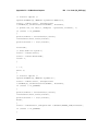
Appendix A—Programming Example
A-1
C/C++ . . . . . . . . . . . . . . . . . . . . . . . . . . . . . . . . . . . . . . . . . . . . . . . . . . . . . A-1
A-2
Visual Basic . . . . . . . . . . . . . . . . . . . . . . . . . . . . . . . . . . . . . . . . . . . . . . . . A-5
A-3
LabVIEW™ . . . . . . . . . . . . . . . . . . . . . . . . . . . . . . . . . . . . . . . . . . . . . . . . . A-6
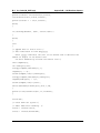
Appendix B—IQ Waveform Capture
B-1
MATLAB Script (getdata_simple_24.m) . . . . . . . . . . . . . . . . . . . . . . . . . . . B-2
B-2
C++ Code (IQ_SCPI.cpp) . . . . . . . . . . . . . . . . . . . . . . . . . . . . . . . . . . . . . . B-5
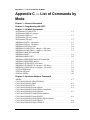
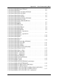
Appendix C—List of Commands by Mode
Appendix D—List of All Commands
Index
Contents-6
PN: 10580-00341 Rev. C
MS2720T PM
Chapter 1 — General Information
1-1
About this Manual
This SCPI Programming Manual provides information for remote operation of the MS2720T
High Performance Handheld Spectrum Analyzer using commands sent from an external
controller via Ethernet or USB connection. This Programming Manual includes the following:
• An overview of Ethernet and USB connection to the instrument.
• An overview of Standard Commands for Programmable Instruments (SCPI) command
structure and conventions.
• The IEEE common commands that are supported by the MS2720T.
• A complete listing and description of all the SCPI commands that can be used to
remotely control functions of the Spectrum Master. The commands are organized by
instrument mode starting in Chapter 3, “All Mode Commands”.
This manual is intended to be used in conjunction with the MS2720T User Guide,
P/N: 10580-00340. Refer to that manual for general information about the MS2720T,
including equipment setup and operating instructions.
1-2
Introduction
This chapter provides a general description of remote programming setup and interface
connections using Ethernet or USB, and sending SCPI commands to the instrument.
1-3
Contacting Anritsu
To contact Anritsu, please visit:
http://www.anritsu.com/contact.asp
From here, you can select the latest sales, select service and support contact information in
your country or region, provide online feedback, complete a “Talk to Anritsu” form to have
your questions answered, or obtain other services offered by Anritsu.
Updated product information can be found on the Anritsu website:
http://www.anritsu.com/
Search for the product model number. The latest documentation is on the product page under
the Library tab.
MS2720T PM
PN: 10580-00341 Rev. C
1-1
1-4
Remote Programming Setup and Interface
1-4
Chapter 1 — General Information
Remote Programming Setup and Interface
Remote programming and operation of the instrument is accomplished via the Ethernet or
the USB interface. The following sections provide information about the interface
connections, cable requirements, and remote operation setup.
Note
If a password has been set for the instrument, to control access via the Anritsu
Web Remote Tools, for example, remote operation using SCPI commands is not
possible.
Ethernet Interface Connection and Setup
The MS2720T fully supports the IEEE-802.3 standard. Most instrument functions (except
power on/off) can be controlled via an Ethernet connection to a PC connected directly (with an
Ethernet cross-over cable) or through a network. The instrument software supports the
TCP/IP network protocol.
Ethernet networking uses a bus or star topology in which all of the interfacing devices are
connected to a central cable called the bus, or are connected to a hub. Ethernet uses the
CSMA/CD access method to handle simultaneous transmissions over the bus. CSMA/CD
stands for Carrier Sense Multiple Access/Collision Detection. This standard enables network
devices to detect simultaneous data channel usage, called a collision, and provides for a
contention protocol. When a network device detects a collision, the CSMA/CD standard
dictates that the data is retransmitted after waiting a random amount of time. If a second
collision is detected, the data is again retransmitted after waiting twice as long. This is
known as exponential back off.
The TCP/IP setup requires the following:
• IP Address: Every computer and electronic device in a TCP/IP network requires an IP
address. An IP address has four numbers (each between 0 and 255) separated by
periods. For example: 128.111.122.42 is a valid IP address.
• Subnet Mask: The subnet mask distinguishes the portion of the IP address that is the
network ID from the portion that is the station ID. The subnet mask 255.255.0.0, when
applied to the IP address given above, would identify the network ID as 128.111 and
the station ID as 122.42. All stations in the same local area network should have the
same network ID, but different station IDs.
• Default Gateway: A TCP/IP network can have a gateway to communicate beyond the
LAN identified by the network ID. A gateway is a computer or electronic device that is
connected to two different networks and can move TCP/IP data from one network to the
other. A single LAN that is not connected to other LANs requires a default gateway
setting of 0.0.0.0. If you have a gateway, then the default gateway would be set to the
appropriate value of your gateway
• Ethernet Address: An Ethernet address is a unique 48-bit value that identifies a
network interface card to the rest of the network. Every network card has a unique
Ethernet address (MAC address) permanently stored into its memory.
1-2
PN: 10580-00341 Rev. C
MS2720T PM
Chapter 1 — General Information
1-4
Remote Programming Setup and Interface
Interface between the instrument and other devices on the network is via a category five
(CAT-5) interface cable connected to a network. This cable uses four twisted pairs of insulated
copper wires terminated into an RJ45 connector. CAT-5 cabling is capable of supporting
frequencies up to 100 MHz and data transfer speeds up to 1 Gbps, which accommodates
1000Base-T, 100Base-T, and 10Base-T networks. CAT-5 cables are based on the EIA/TIA 568
Commercial Building Telecommunications Wiring Standard developed by the Electronics
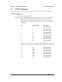
Industries Association. A pinout diagram is shown in Table 1-1.
Table 1-1.
8-pin Ethernet RJ45 Connector Pinout Diagram
87654321
Pin
Name
Description
Wire Color
1
TX+
Transmit data (> +3 volts)
White/Orange
2
TX–
Transmit data (< –3 volts)
Orange
3
RX+
Receive data (> +3 volts)
White/Green
4
–
Not used (common mode termination)
Blue
5
–
Not used (common mode termination)
White/Blue
6
RX–
Receive data (< –3 volts)
Green
7
–
Not used (common mode termination)
White/Brown
8
–
Not used (common mode termination)
Brown
TCP/IP connectivity requires setting up the parameters described at the beginning of this
section. The following is a brief overview of how to set up a general LAN connection on the
MS2720T.
Note
You may need to consult your network documentation or network administrator for
assistance in configuring your network setup.
LAN Connection
The RJ45 connector is used to connect the instrument to a local area network. Integrated into
this connector are two LEDs. The amber LED indicates the presence of LAN voltages (a live
LAN connection) while the green LED flashes to show that LAN traffic is present. The
instrument IP address is set by pressing the Shift key, then the System (8) key followed by
the System Options soft key and the Ethernet Config soft key. The instrument IP address can
be set automatically using DHCP, or manually by entering the desired IP address, gateway
address and subnet mask.
MS2720T PM
PN: 10580-00341 Rev. C
1-3
1-4
Remote Programming Setup and Interface
Chapter 1 — General Information
An active Ethernet cable must be connected to the instrument before it is turned
on in order to enable the Ethernet port for DHCP or for a static IP address.
Note
Depending on local conditions, the port may remain enabled when changing from
DHCP to static IP address, when changing from static IP address to DHCP, or
when temporarily disconnecting the Ethernet cable.
If the port becomes disabled, verify that an active Ethernet cable is attached to the
instrument, then cycle the power off and back on.
Dynamic Host Configuration Protocol (DHCP) is an Internet protocol that automates the
process of setting IP addresses for devices that use TCP/IP, and is the most common method
of configuring a device for network use.
To determine if a network is set up for DHCP, connect the instrument to the network and
select DHCP protocol in the Ethernet Config menu. Power cycle the instrument. If the network
is set up for DHCP, the assigned IP address should be displayed briefly after the power-up
sequence.
To display the IP address of the instrument, press the Shift key followed by System (8), then
the System Options soft key and Ethernet Config.
USB Interface Connection and Setup
The Universal Serial Bus (USB) architecture is a high-performance networking standard that
is considered “plug and play” compatible. The USB driver software is automatically detected
and configured by the operating system of the devices that are connected to the bus. The
instrument conforms to the USB 2.0 standard and is a USB “full-speed” device that supports
data rates of up to 10 Mbps with the following restrictions:
• One USB network can support up to 127 devices.
• The maximum length of USB cables between active devices is 5 meters for USB 2.0 and
3 meters for USB 1.0.
You must have NI-VISA 2.5 or later installed on the controller PC and you must select the
VISA library (visa32.dll) as a reference in a Visual Basic project. For remote USB control, the
controlling PC must have a version of VISA installed that supports USBTMC (USB Test and
Measurement Class) devices.
The USB 2.0 Mini-B device connector can be used to connect the MS2720T directly to a PC.
The first time the instrument is connected to a PC, the normal USB device detection by the
computer operating system takes place.
1. Power on the instrument and controller PC and wait for the systems to power up
completely.
2. Connect the USB cable mini-B connector to the instrument.
1-4
PN: 10580-00341 Rev. C
MS2720T PM
Chapter 1 — General Information
1-4
Remote Programming Setup and Interface
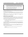
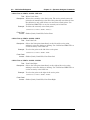
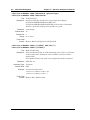
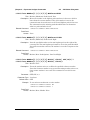
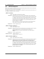
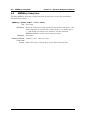
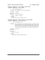
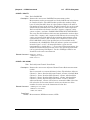
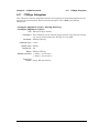
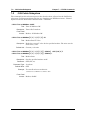
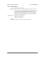
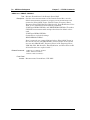
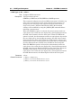
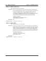
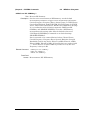
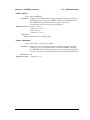
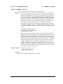
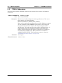
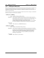
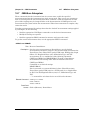
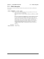
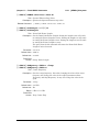
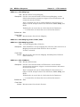
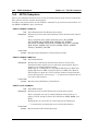
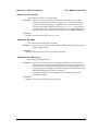
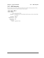
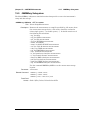
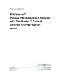
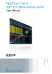
3. Connect the USB cable A connector to the controller PC USB host port. The controller
PC should indicate “New Hardware Found” if the combination of USB VID/PID/Serial
Number has never been connected to this controller PC.
Figure 1-1.
Found New Hardware Wizard
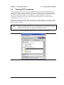
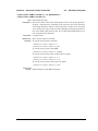
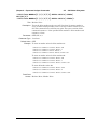
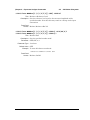
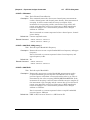
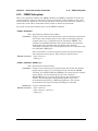
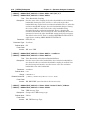
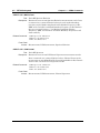
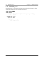
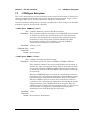
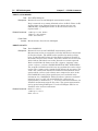
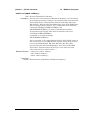
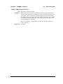
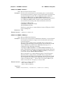
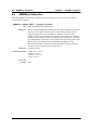
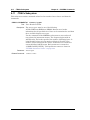
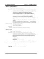
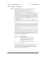
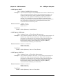
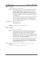
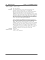
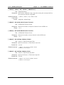
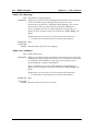
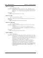
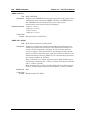
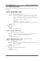
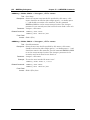
4. Select to allow the Wizard to search for and install the USB software automatically.
Figure 1-2.
MS2720T PM
Found New Hardware Wizard
PN: 10580-00341 Rev. C
1-5
1-4
Remote Programming Setup and Interface
Chapter 1 — General Information
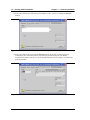
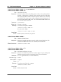
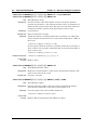
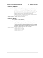
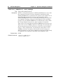
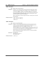
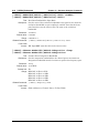
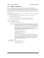
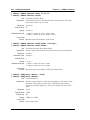
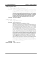
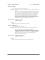
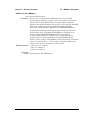
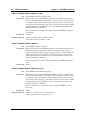
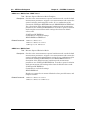
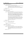
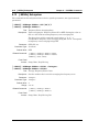
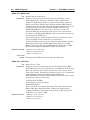
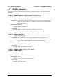
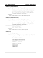
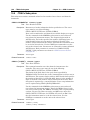
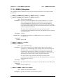
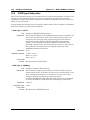
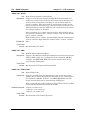
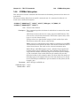
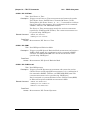
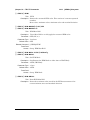
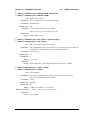
5. After the software finishes installing, close the Wizard by clicking Finish.
Figure 1-3.
1-6
Found New Hardware Wizard
PN: 10580-00341 Rev. C
MS2720T PM
Chapter 1 — General Information
1-5
1-5
Sending SCPI Commands
Sending SCPI Commands
SCPI commands can be sent to the instrument through any Virtual Instrument Software
Architecture (VISA) controller. VISA is a commonly used API in the Test and Measurement
industry for communicating with instruments from a PC. The physical connection between
the PC and the Spectrum Master can be Ethernet or USB. NI-VISA is the National
Instruments implementation of the VISA I/O standard. Information and downloads are
available at http://www.ni.com/visa/.
The following example describes the verification that a VISA controller can interact with the
instrument. The images shown and the instructions for your instrument and software may
differ from the examples.
Note
Before remote operation, confirm that the instrument is not in the Menu screen.
Sending commands while this screen is displayed is an invalid operation. Refer to
the instrument User Guide for information on the Menu screen.
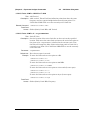
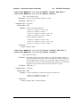
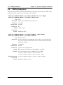
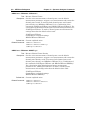
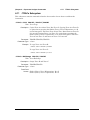
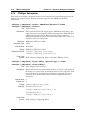
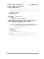
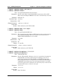
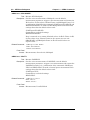
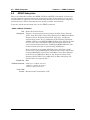
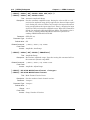
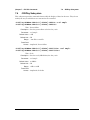
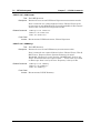
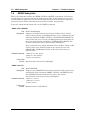
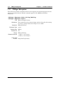
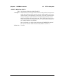
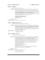
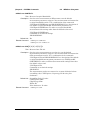
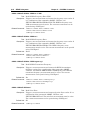
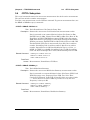
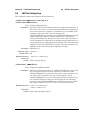
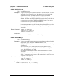
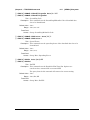
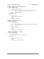
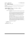
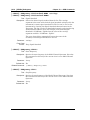
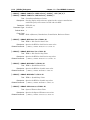
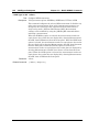
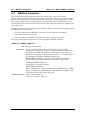
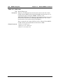
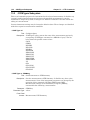
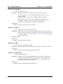
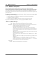
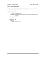
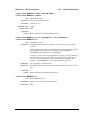
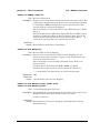
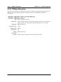
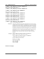
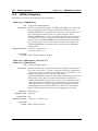
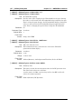
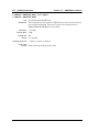
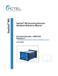
1. On the PC, run VISA Interactive Control and double-click on the instrument.
Figure 1-4.
MS2720T PM
VISA Interactive Control
PN: 10580-00341 Rev. C
1-7
1-5
Sending SCPI Commands
Chapter 1 — General Information
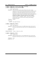
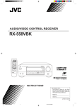
2. Select the viWrite tab and execute the default *IDN? write by clicking the Execute
button.
Figure 1-5.
VISA Interactive Control viWrite Tab
3. Select the viRead tab and click the Execute button. If the PC is connected to the
instrument, the command returns the following information from the Buffer:
manufacturer name (“Anritsu”), model number/options, serial number, and firmware
package number.
Figure 1-6.
1-8
VISA Interactive Control viRead Tab
PN: 10580-00341 Rev. C
MS2720T PM
Chapter 2 — Programming with SCPI
2-1
Introduction
This chapter provides an introduction to SCPI programming that includes descriptions of the
command types, hierarchical command structure, command subsystems, data parameters
and notational conventions.
2-2
Introduction to SCPI Programming
The Standard Commands for Programmable Instruments (SCPI) defines a set of standard
programming commands for use by all SCPI compatible instruments. SCPI is intended to give
the user a consistent environment for program development. It does so by defining controller
messages, instrument responses, and message formats for all SCPI compatible instruments.
SCPI commands are messages to the instrument to perform specific tasks. The MS272xC
command set includes:
• “SCPI Common Commands” on page 2-1
• “SCPI Required Commands” on page 2-2
• “SCPI Optional Commands” on page 2-2
Note
This instrument follows the SCPI standard but is not fully compliant with the
standard.
SCPI Common Commands
Some common commands are defined in the IEEE-488.2 standard and must be implemented
by all SCPI compatible instruments. These commands are identified by the asterisk (*) at the
beginning of the command keyword. These commands are defined to control instrument
status registers, status reporting, synchronization, and other common functions. The common
commands supported by the Spectrum Master are shown below.
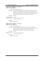
*IDN?
Title: Identification Query
Description: This command returns the following information in <string> format
separated by commas: manufacturer name (“Anritsu”), model
number/options, serial number, firmware package number. The model
number and options are separated by a “/” and each option is separated
by a “/”.
For example, the return string might look like:
“Anritsu,MS2722C/3/2,62011032,1.23”
MS2720T PM
PN: 10580-00341 Rev. C
2-1
2-2
Introduction to SCPI Programming
Chapter 2 — Programming with SCPI
*RST
Title: Reset
Description: This command restores parameters in the current application as well as
system settings to their factory default values.
System settings affected by this command are Ethernet configuration,
language, volume and brightness. Note that the unit will power-cycle
after this command is executed.
After executing this command communication will be lost. Wait a
minimum of 60 seconds before re-establishing communication.
Front Panel
Access: Shift-8 (System), System Options, Reset, Factory Defaults
See Also::SYSTem:PRESet
SCPI Required Commands
The required SCPI commands supported by the MS272xC are listed in the Table 2-1. These
command work in all measurement modes and are described in Chapter 3.
Table 2-1.
SCPI Required Commands
:STATus
:SYSTem
SCPI Optional Commands
Table 2-2 lists the optional SCPI commands that comprise the majority of the command set
described in this document. These commands control most of the programmable functions of
the MS272xC.
Table 2-2.
2-2
SCPI Optional Commands
:ABORt
:FETCh
:MEASure
:TRACe
:CALCulate
:FORMat
:MMEMory
:TRIGger
:CALibration
:INITiate
:READ
:UNIT
:CONFigure
:INPut
:SENSe
[:SENSe]
:DISPlay
:INSTrument
:SOURce
PN: 10580-00341 Rev. C
MS2720T PM
Chapter 2 — Programming with SCPI
2-2
Introduction to SCPI Programming
The SCPI optional commands are sorted by measurement modes, and commands may be
repeated in more than one mode.
• Chapter 3, “All Mode Commands”
• Chapter 4, “Spectrum Analyzer Commands”
• Chapter 5, “Tracking Generator Commands”
• Chapter 6, “CDMA Commands”
• Chapter 7, “EV-DO Commands”
• Chapter 8, “WCDMA Commands”
• Chapter 9, “TDSCDMA Commands”
• Chapter 10, “GSM Commands”
• Chapter 11, “Fixed WiMAX Commands”
• Chapter 12, “Mobile WiMAX Commands”
• Chapter 13, “LTE Commands”
• Chapter 14, “TD-LTE Commands”
• Chapter 15, “AM/FM/PM Commands”
MS2720T PM
PN: 10580-00341 Rev. C
2-3
2-3
Subsystem Commands
2-3
Chapter 2 — Programming with SCPI
Subsystem Commands
Subsystem commands control all instrument functions and some general purpose functions.
All subsystem commands are identified by the colon used between keywords, as in
:INITiate:CONTinuous.
The following information is provided for each subsystem command described in the following
chapters.
• The command name, see “Command Names” on page 2-4.
• The path from the subsystem root command, see “Hierarchical Command Structure” on
page 2-5.
• The query form of the command (if applicable), see “Query Commands” on page 2-6.
• The command title
• A description of the purpose of the command.
• The data parameters used as arguments for the command, see “Data Parameters” on
page 2-8. This may include the parameter type and the available parameter choices.
Command Names
Typical SCPI commands consist of one or more keywords, parameters, and punctuation. SCPI
command keywords can be a mixture of upper and lower case characters. Except for common
commands, each keyword has a long and a short form. In this manual, the long form is
presented with the short form in upper case and the remainder in lower case. For example,
the long form of the command keyword to control the instrument display is :DISPlay.
The short form keyword is usually the first four characters of the long form (example: DISP
for DISPlay). The exception to this is when the long form is longer than four characters and
the fourth character is a vowel. In such cases, the vowel is dropped and the short form
becomes the first three characters of the long form. Example: the short form of the keyword
:POWer is :POW.
Some command keywords may have a numeric suffix to differentiate between multiple
instrument features such as multiple trace options. For example; keywords
:TRACe[:DATA]{1|2|3}, :TRACe1, or :TRACe3.
Note
In the previous paragraph, :TRACe is identical to :TRACe1. If a numeric suffix it
not included in a command, the first option is implied. Curly brackets { } designate
optional keyword parameters. Square brackets [ ] designate optional command
keywords.
As with any programming language, the exact command keywords and command syntax
must be used. The syntax of the individual commands is described in detail in the
programming command chapters. Unrecognized versions of long form or short form
commands, or improper syntax, will generate an error.
2-4
PN: 10580-00341 Rev. C
MS2720T PM
Chapter 2 — Programming with SCPI
2-3
Subsystem Commands
Long Format vs. Short Format
Each keyword has a long format and a short format. The start frequency can be specified by
:SENSe:FREQuency:STARt or :SENS:FREQ:STAR. The capital letters in the command
specification indicate the short form of the command. A mixture of the entire short form
elements with entire long form elements of each command is acceptable. For example,
:SENS:FREQuency:STAR is an acceptable form of the command. However,
:SENS:FREQuen:STA is not an acceptable form of the command because :FREQuen is not the
entire short or long form of the command element.
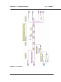
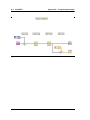
Hierarchical Command Structure
All SCPI commands, except the common commands, are organized in a hierarchical structure
similar to the inverted tree file structure used in most computers. The SCPI standard refers
to this structure as “the Command Tree.” The command keywords that correspond to the
major instrument control functions are located at the top of the command tree. The root
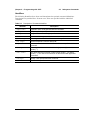
command keywords for the MS272xC SCPI command set are shown in Figure 2-1.
root
:ABORt
:FETCh
:MEASure
:STATus
:UNIT
:CALCulate
:FORMat
:MMEMory
:SYSTem
[:SENSe]
:CALibration
:INITiate
:READ
:TRACe
:CONFigure
:INPut
:SENSe
:TRIGger
:DISPlay
:INSTrument
:SOURce
Figure 2-1.
MS2720T PM
SCPI Command Tree
PN: 10580-00341 Rev. C
2-5
2-3
Subsystem Commands
Chapter 2 — Programming with SCPI
All MS272xC SCPI commands, except the :ABORt command, have one or more subcommands
(keywords) associated with them to further define the instrument function to be controlled.
The subcommand keywords may also have one or more associated subcommands (keywords).
Each subcommand level adds another layer to the command tree. The command keyword and
its associated subcommand keywords form a portion of the command tree called a command
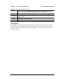
subsystem. The :CONFigure command subsystem is shown in Figure 2-2.
:CONFigure
:ACPower
:OBWidth
:CHPower
:OTA
:DEMOD
:Pfail
:FSTRength
:PM
:MEASure
:PVTFrame
:PVTSlot
:MENU
:RF
:SPECTRUM
:MULTi
:SINGle
:SUMMARY
:VVM
Figure 2-2.
SCPI :CONFigure Subsystem
A colon (:) separates each subsystem. For example, the command
:SENSe:FREQuency:STARt <freq> sets the start frequency. The start frequency is part of
the :FREQuency subsystem which is part of the :SENSe subsystem. Stop frequency is also
part of the :SENSe:FREQuency subsystem. It is specified by :SENSe:FREQuency:STOP.
Query Commands
All commands, unless specifically noted in the commands syntax descriptions, have a query
form. As defined in IEEE-488.2, a query is a command with a question mark symbol
appended (examples: *IDN? and :OPTions?). When a query form of a command is received,
the current setting associated with the command is placed in the output buffer. Query
commands always return the short form of the parameter unless otherwise documented.
Boolean values are returned as 1 or 0, even when they can be set as on or off.
2-6
PN: 10580-00341 Rev. C
MS2720T PM
Chapter 2 — Programming with SCPI
2-3
Subsystem Commands
Identifiers
The following identifiers have been used throughout the optional command definitions.
Descriptions are provided here. In most cases, units are specified with the individual
command.
Table 2-3.
Description of Command Identifiers
Identifier
Description
<amplitude>
Amplitude value. Units specified with the command.
<freq>
Frequency. Units specified with the command.
<integer>
Integer value, no units. Range specified with the command.
<number>
Numeric value, integer, or real.
<percentage>
Percentage value from 0 to 100. Units are always %.
<rel ampl>
Relative amplitude. Units are always dB.
<x-parameter>
Parameter value in the units of the x-axis. Units are specified with the
command.
<string>
The string should be enclosed in either single quotes (‘ ’) or double
quotes (“ ”).
<file name>
The name should be enclosed in either single quotes (‘ ’) or double
quotes (“ ”). The need for an extension is documented with applicable
commands.
<voltage>
Voltage. Units specified with the command.
<current>
Current. Units specified with the command.
MS2720T PM
PN: 10580-00341 Rev. C
2-7
2-3
Subsystem Commands
Chapter 2 — Programming with SCPI
Data Parameters
Data parameters, referred to simply as “parameters,” are the quantitative values used as
arguments for the command keywords. The parameter type associated with a particular SCPI
command is determined by the type of information required to control the particular
instrument function. For example, Boolean (ON | OFF) type parameters are used with
commands that control switch functions.
Some command descriptions specify the type of data parameter to be used with each
command. The most commonly used parameter types are numeric, extended numeric,
discrete, and Boolean.
Numeric
Numeric parameters comprise integer numbers or any number in decimal or scientific
notation, and may include polarity signs. This includes <NR1>, <NR2>, and <NR3>
numeric data as defined in “Data Parameter Notations” below. Parameters that accept
all three <NR> formats are designated <NRf> throughout this document.
Extended Numeric
Extended numeric parameters include values such as MAXimum and MINimum.
Discrete
Discrete parameters, such as INTernal and EXTernal, are used to control program
settings to a predetermined finite value or condition.
Boolean
Boolean parameters represent binary conditions and may be expressed as ON, OFF or
1, 0.
Data Parameter Notations
The following syntax conventions are used for data parameter descriptions in this manual:
Table 2-4.
<arg>
<bNR1>
Parameter Notations (1 of 2)
::=a generic command argument consisting of one or more of the other data types
::=boolean values in <NR1> format; numeric 1 or 0
<boolean>
::=ON | OFF. Can also be represented as 1 or 0, where 1 means ON and 0 means
OFF
Boolean parameters are always returned as 1 or 0 in <NR1> format by query
commands
<integer>
::=an unsigned integer without a decimal point (implied radix point)
2-8
<NR1>
::=a signed integer without a decimal point (implied radix point)
<NR2>
::=a signed number with an explicit radix point
<NR3>
::=a scaled explicit decimal point numeric value with and exponent (e.g., floating
point number)
<NRf>
::=<NR1>|<NR2>|<NR3>
PN: 10580-00341 Rev. C
MS2720T PM
Chapter 2 — Programming with SCPI
Table 2-4.
2-3
Subsystem Commands
Parameter Notations (2 of 2)
<nv>
::=SCPI numeric value: <NRf>|MINimum|MAXimum|UP|DOWN|DEFault|NAN
(Not A Number)|INFinity|NINFinity (Negative Infinity) or other types
<char>
::=<CHARACTER PROGRAM DATA> Examples: CW, FIXed, UP, and DOWN
<string>
::=<STRING PROGRAM DATA> ASCII characters enclosed by double quotes For
example: “OFF”
<block>
::=IEEE-488.2 block data format
<NA>
::=Not Applicable
Unit Suffixes
Unit suffixes are not required for data parameters, provided the values are scaled for the
global default units. The Spectrum Master SCPI default units are: Hz (Hertz) for frequency
related parameters s (seconds) for time related parameters, and m (meters) for distance
related parameters.
MS2720T PM
PN: 10580-00341 Rev. C
2-9
2-4
Notational Conventions
2-4
Chapter 2 — Programming with SCPI
Notational Conventions
The SCPI interface standardizes command syntax and style that simplifies the task of
programming across a wide range of instrumentation. As with any programming language,
the exact command keywords and command syntax must be used. Unrecognized commands
or improper syntax will not function.
Table 2-5.
Notational Conventions
:
A colon links command keywords together to form commands. The colon is not an
actual part of the keyword, but is a signal to the SCPI interface parser. A colon must
precede a root keyword immediately following a semicolon (see “Notational
Examples” on page 2-11).
;
A semicolon separates commands if multiple commands are placed on a single
program line.
[]
Square brackets enclose one or more optional keywords.
{}
Braces enclose one or more keyword or command parameters that may be
included one or more times.
|
A vertical bar indicates “or” and is used to separate alternative parameter options.
Example: ON | OFF is the same as ON or OFF.
<>
Angle brackets enclose parameter descriptions.
::=
Means “is defined as” For example: <a>::=<b><c> indicates that <b><c> can
replace <a>.
sp
Space, referred to as white space, must be used to separate keywords from their
associated data parameters. It must not be used between keywords or inside
keywords.
XXX
Indicates a root command name
For further information about SCPI command syntax and style, refer to the Standard
Commands for Programmable Instruments (SCPI) 1999.0 document.
2-10
PN: 10580-00341 Rev. C
MS2720T PM
Chapter 2 — Programming with SCPI
2-5
2-5
Notational Examples
Notational Examples
Table 2-6 provides examples of valid command syntax:
Table 2-6.
Creating Valid Commands
Command Specification
[:SENSe]:FREQuency:STARt <freq>
Valid Forms
The following all produce the same result:
:SENSe:FREQuency:STARt 1 MHZ
:SENS:FREQ:STAR 1 MHZ
:sense:frequency:start 1000000
:FREQ:STAR 1000 kHZ
:CALCulate:MARKer{1|2|3|4|5|6}:X
<x-parameter>
The first 2 commands set the location of
marker 1. The third command sets the location
of marker 2.
:CALC:MARK:X 1 GHZ
:CALC:MARK1:X 1 GHZ
:CALC:MARK2:X 2 GHZ
:UNIT:POWer dBM|DBV|DBMV|DBUV|V|W
The following commands are identical:
:UNIT:POWer dBM
:unit:pow dBm
:INITiate:CONTinuous OFF|ON|0|1
The following commands are identical:
:INITiate:CONTinuous OFF
:init:cont 0
Command statements read from left to right and from top to bottom. In the command
statement above, the :FREQuency keyword immediately follows the :SENSe keyword with no
separating space. A space (sp) is used between the command string and its argument.
Note that the first keyword in the command string does not require a leading colon; however,
it is good practice to always use a leading colon for all keywords. Note also that the :SENSe
keyword is optional. This is a SCPI convention for all voltage or signal source type
instruments that allows shorter command statements to be used.
The following is an example of a multiple command statement that uses two separate
commands in a single statement:
:FREQuency:STARt 10E6;:FREQuency:STOP 20E9
Note
MS2720T PM
A semicolon is used to join the commands and a leading colon used immediately
after the semicolon to start the second command.
PN: 10580-00341 Rev. C
2-11
2-6
Formatting Conventions
Chapter 2 — Programming with SCPI
Command Terminators
The <new line> character (ASCII 10) in the last data byte of a command string is used as a
command terminator. Use of a command terminator will reset the command path to the root
of the tree.
2-6
Formatting Conventions
This manual uses the following conventions in describing SCPI commands.
Table 2-7.
Formatting Conventions
:COMMands:LOOK:LIKE:THIS
Commands are formatted to differentiate them
from their description.
:COMMand:QUERies:LOOK:LIKE:THIS?
The query form of the command is followed by
a “?”
Front-panel key sequences use this formatting
Front-panel key presses are formatted to
differentiate them from text descriptions. Key
presses are separated by a comma (“,”).
<identifier>
Identifiers are enclosed in “< >”. They indicate
that some type of data must be provided. See
Table 2-3 for details on the types of identifiers.
|
The “|” indicates that a choice must be made.
[optional input]
Optional input is be enclosed in “[ ]”. The “[ ]”
are not part of the command.
2-12
PN: 10580-00341 Rev. C
MS2720T PM
Chapter 2 — Programming with SCPI
2-7
2-7
Parameter Names
Parameter Names
The following tables list the parameter options for the :TRACe:PREamble? command in
each supported measurement mode.
MS2720T PM
PN: 10580-00341 Rev. C
2-13
2-7
Parameter Names
Chapter 2 — Programming with SCPI
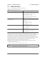
Spectrum Analyzer Parameter Names
Table 2-8.
Available Parameters in Spectrum Analyzer Mode (1 of 6)
Parameter Name
Description
SN
Instrument serial #
UNIT_NAME
Instrument name
DESCR
Trace name
DATE
Trace date/time
BASE_VER
Base FW version
APP_NAME
Application name
APP_VER
Application FW version
UNITS
Amplitude units
CENTER_FREQ
Center frequency
SPAN
Frequency span
FREQ_STEP
Frequency step size
RBW
Resolution bandwidth
RBW_TYPE
RBW coupling auto/manual
VBW
Video bandwidth
VBW_TYPE
VBW coupling auto/manual
RBW_VBW_RATIO
RBW/VBW ratio
SPAN_RBW_RATIO
Span/RBW ratio
INPUT_ATTEN
Input attenuation
ATTEN_TYPE
Attenuation coupling auto/manual
REFERENCE_LEVEL
Reference level
SCALE
y-axis scale
PREAMP_SET
Preamp state
REF_LEVEL_OFFSET
Reference level offset
DETECTION
Detection type
TRACE_AVERAGE
Number of traces to average
SWEEP_TYPE
Single/continuous
CURRENT_SIGNAL
Current signal index
CURRENT_CHANNEL
Current signal channel
TRACE_MODE
Normal/Avg/Max
2-14
PN: 10580-00341 Rev. C
MS2720T PM
Chapter 2 — Programming with SCPI
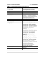
Table 2-8.
2-7
Parameter Names
Available Parameters in Spectrum Analyzer Mode (2 of 6)
Parameter Name
Description
TRACE_STATUS
TRACE_A_VIEW_NOT_BLANK:
0x0000000000000001
TRACE_A_WRITE_NOT_HOLD:
0x0000000000000002
TRACE_A_DATA_VALID:
0x0000000000000004
TRACE_B_VIEW_NOT_BLANK:
0x0000000000010000
TRACE_B_WRITE_NOT_HOLD:
0x0000000000020000
TRACE_B_DATA_VALID:
0x0000000000040000
TRACE_C_VIEW_NOT_BLANK:
0x0000000100000000
TRACE_C_WRITE_NOT_HOLD:
0x0000000200000000
TRACE_C_DATA_VALID:
0x0000000400000000
TRACE_C_IS_B_MINUS_A_ON:
0x0000001000000000
TRACE_C_IS_A_MINUS_B_ON:
0x0000002000000000
TRACE_COUNT
Number of traces averaged
UI_DATA_POINTS
Number of display points
IMPEDANCE
Input impedance
REFERENCE_FREQUENCY
Reference freq
SET_SWEEP_TIME
Minimum sweep time setting
TRIGGER_TYPE
Trigger type
VIDEO_TRIGGER_LEVEL
Video trigger level
TRIGGER_POSITION
Trigger position as a percent of the display
PEAK_THRESHOLD
Marker peak search threshold
MARKER_TABLE
Marker table status
ACTIVE_ MEASUREMENT
Current measurement
ANTENNA
Antenna index
OCC_BW_METHOD
Occupied bandwidth method
OCC_BW_PERCENT
Occupied bandwidth % of power setting
OCC_BW_DBC
Occupied bandwidth dBc setting
OCC_BW_MEASURED_ dB
Occupied bandwidth measured dBc value
MS2720T PM
PN: 10580-00341 Rev. C
2-15
2-7
Parameter Names
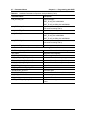
Table 2-8.
Chapter 2 — Programming with SCPI
Available Parameters in Spectrum Analyzer Mode (3 of 6)
Parameter Name
Description
OCC_BW_MEASURED_ PERCENT
Occupied bandwidth measured % value
OCC_BW_VALUE
Measured occupied bandwidth
OCC_BW_LINE_ MARKER_INFO
Mask off 16 bits at a time to get the display
point location of the 3 OBW display indicators
CH_PWR_WIDTH
Channel power integration bandwidth
CH_PWR_VALUE
Measured channel power
CH_PWR_DENSITY
Measured channel power density
CH_PWR_LINE_ MARKER_INFO
Mask off 16 bits at a time to get the display
point location of the 2 channel power display
indicators
ACPR_MAIN_CH_BW
ACPR main channel bandwidth
ACPR_ADJC_CH_BW
ACPR adjacent channel bandwidth
ACPR_CHANNEL_ SPACING
ACPR channel spacing
ACPR_MAIN_CH_PWR
ACPR measured main channel power
ACPR_UPPER_CH_PWR
ACPR measured upper channel power
ACPR_LOWER_CH_ PWR
ACPR measured lower channel power
ACPR_LOWER_CH_ LINE_MARKER_INFO
Mask off 16 bits at a time to get the display
point location of the 2 ACPR lower channel
display indicators
ACPR_MAIN_CH_LINE_ MARKER_INFO
Mask off 16 bits at a time to get the display
point location of the 2 ACPR main channel
display indicators
ACPR_UPPER_CH_ LINE_MARKER_INFO
Mask off 16 bits at a time to get the display
point location of the 2 ACPR upper channel
display indicators
AM_FM_DEMOD_VOL
AM/FM demod volume
AM_FM_DEMOD_ FREQUENCY
AM/FM demod freq
AM_FM_DEMOD_TYPE
AM/FM demod type
AM_FM_DEMOD_TIME
AM/FM demod time
AM_FM_LINE_ MARKER
Display point location of the demodulation
frequency
BEAT_FREQUENCY_ OSC_FREQUENCY
BFO oscillator freq
CI_C_TYPE
C/I measurement carrier type
CI_C_VALUE
C/I measurement measured carrier power
CI_I_BB_VALUE
C/I measurement measured broadband
interference power
CI_I_NB_VALUE
C/I measurement measured narrowband
interference power
2-16
PN: 10580-00341 Rev. C
MS2720T PM
Chapter 2 — Programming with SCPI
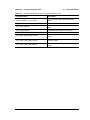
Table 2-8.
2-7
Parameter Names
Available Parameters in Spectrum Analyzer Mode (4 of 6)
Parameter Name
Description
CI_I_WB_VALUE
C/I measurement measured wideband
interference power
CI_BB_VALUE
C/I measurement with broadband interference
CI_NB_VALUE
C/I measurement with narrowband interference
CI_WB_VALUE
C/I measurement with wideband interference
MKR_SPA_FREQNx
Marker x frequency (where x is the marker
number 0 to 11, 0 represent the reference
marker #1 and 1 represent delta marker #1, 2
represent reference marker #2, and 3
represent delta marker #2, and so on)
MKR_SPA_POINTx
Reference marker x display point
MKR_SPA_MAGNTx
Reference marker x magnitude
MKR_SPA_PRCNTx
Reference marker x display percentage
MKR_SPA_FLAGSx
Reference marker x flags:
SPA_MKR_FLAG_ON_OFF: 0x00000001
SPA_MKR_FLAG_DELTA_MKR: 0x00000002
SPA_MKR_FLAG_SELECTED: 0x00000004
SPA_MKR_FLAG_DATA_INVALID:
0x00000008
SPA_MKR_FLAG_DATA_STALE: 0x00000010
SPA_MKR_FLAG_FIXED: 0x00000020
SPA_MKR_FLAG_MASK: 0x000000FF
SPA_MKR_FLAG_DISPL_AMPL_HZ:
0x00000100
SPA_MKR_FLAG_DISPL_AMPL_PER_HZ:
0x00000200
SPA_MKR_FLAG_DISP_FLAG: 0x00000F00
SPA_MKR_FLAG_RELATIVE: 0x00001000
SPA_MKR_STANDARD: 0x10000000
SPA_MKR_FIELD_STRENGHT: 0x20000000
SPA_MKR_NOISE: 0x30000000
SPA_MKR_COUNTER: 0x40000000
SPA_MKR_TIME: 0x50000000
MKR_SPA_REF_TOx
Specifies which marker is the marker x
reference to
MKR_SPA_TRACex
Specifies which trace the marker x is for.
MS2720T PM
PN: 10580-00341 Rev. C
2-17
2-7
Parameter Names
Table 2-8.
Chapter 2 — Programming with SCPI
Available Parameters in Spectrum Analyzer Mode (5 of 6)
Parameter Name
Description
LIM_LFLAGS_UP
Upper limit flags:
LIMIT_FLAG_ON: 0x00000004
LIMIT_FLAG_ALARM_ON: 0x00000002
LIM_FREQNC_UPx
Upper limit point x freq (where x is the limit
point number starting with 0)
LIM_MAGNTD_UPx
Upper limit point x amplitude
LIM_LFLAGS_LO
Lower limit flags:
LIMIT_FLAG_ON: 0x00000004
LIMIT_FLAG_ALARM_ON: 0x00000002
LIM_FREQNC_LOx
Lower limit point x freq (where x is the limit
point number starting with 0)
LIM_MAGNTD_LOx
Lower limit point x amplitude
Parameters Related to Tracking Generator
EXTERNAL_GAIN_LOSS
Generator External Gain/Loss Setting
SG_FREQ
Generator CW Frequency
TG_GEN_SELECT Generator
CW/Tracking Mode Selection
TG_IL_ABS_AVG_PWR_VALUE
Generator Power Statistics (Average Value)
TG_IL_ABS_MAX_PWR_VALUE
Generator Power Statistics (Max Value)
TG_IL_ABS_MIN_PWR_VALUE
Generator Power Statistics (Min Value)
TG_LEVEL_1 Generator
Output Power Level
TG_S21_NORMALIZE_ON_OFF
Generator Normalize Measurement
GENERATOR_OUTPUT
Generator State
TG_REF_POSITION
Normalized Trace Reference Position
TG_REF_AMPLITUDE
Reference Amplitude at the Reference Position
TG_SCALE
Normalized Trace Scale
ACPR_UPPER_ALT_CH_PWR
ACPR measured upper alternate channel
power
2-18
PN: 10580-00341 Rev. C
MS2720T PM
Chapter 2 — Programming with SCPI
Table 2-8.
2-7
Parameter Names
Available Parameters in Spectrum Analyzer Mode (6 of 6)
Parameter Name
Description
ACPR_LOWER_ALT_CH_PWR
ACPR measured lower alternate channel
power
TG_S21_NORMALIZE_ON_OFF
TG Normalization State
TG_IL_REL_STATS
TG Transmission Measurement Statistics Table
State
TG_IL_ABS_STATS
Generator Power Statistics Table State
TG_REF_LEVEL_OFFSET
TG Transmission Offset
TG_IL_REL_MAX_PWR_VALUE
TG Transmission Measurement Statistics (Max
Value)
TG_IL_REL_AVG_PWR_VALUE
TG Transmission Measurement Statistics
(Average Value)
TG_IL_REL_MIN_PWR_VALUE
TG Transmission Measurement Statistics (Min
Value)
MS2720T PM
PN: 10580-00341 Rev. C
2-19
2-7
Parameter Names
Chapter 2 — Programming with SCPI
GSM Parameter Names
Table 2-9.
Available Parameters in GSM Mode
Parameter Name
Description
SN
Instrument serial #
UNIT_NAME
Instrument name
TYPE
The data type (Setup or Data)
DESCR
Trace name
DATE
Trace date/time
BASE_VER
Base FW version
APP_NAME
Application name
APP_VER
Application FW version
APP_MODE
Application Mode
REFERENCE_LEVEL
Reference Level
CENTER_FREQ
Center freq
SIGNAL_STANDARD
Current signal standard (the value is the index
of the signal standard list, where a value of 1 is
the first index in the list)
CHANNEL
Current channel
POWER_OFFSET
Applied power offset
REFERENCE_FREQUENCY
Selected external reference frequency
UNITS
Amplitude units
CURRENT_VIEW
Current view
CURRENT_MEASUREMENTS
Current measurements
DYNAMIC_ATTENUATION
Dynamic range on/off
SPAN
Frequency span
MANUAL_SYSTEM_SELECT
GSM/EDGE select
CURRENT_SPECTRUM_VIEW
Current spectrum view (single or multiple
channel spectrum)
I_Q_VIEW
IQ view
RUN_HOLD
Run/Hold on/off
MC_SPECTRUM_START_FREQ
Multi-channel spectrum start frequency
MC_SPECTRUM_STOP_FREQ
Multi-channel spectrum stop frequency
MC_CHANNEL_CURSOR
Multi-channel spectrum channel cursor (used
for markers)
MC_FREQ_CURSOR
Multi-channel spectrum frequency cursor (used
for markers)
TEST_MODEL
Current pass fail model being tested
2-20
PN: 10580-00341 Rev. C
MS2720T PM
Chapter 2 — Programming with SCPI
2-7
Parameter Names
WiMAX, Mobile WiMAX Parameter Names
Table 2-10. Available Parameters in WiMAX and Mobile WiMAX Mode (1 of 2)
Parameter Name
Description
SN
Instrument serial #
UNIT_NAME
Instrument name
TYPE
The data type (Setup or Data)
DESCR
Trace name
DATE
Trace date/time
BASE_VER
Base FW version
APP_NAME
Application name
APP_VER
Application FW version
APP_MODE
Application Mode
REFERENCE_LEVEL
Reference Level
UNITS
Amplitude units
SCALE
Y axis scale
CENTER_FREQ
Center freq
SIGNAL_STANDARD
Current signal standard (the value is the index
of the signal standard list, where a value of 0 is
the first index in the list)
CHANNEL
Current channel
POWER_OFFSET
Applied power offset
REFERENCE_FREQUENCY
Selected external reference frequency
UNITS
Amplitude units
CURRENT_VIEW
Current view
CURRENT_MEASUREMENTS
Current measurements
DYNAMIC_ATTENUATION
Dynamic range on/off
SPAN
Frequency span
PVT_FRAME_START_TIME
Power vs. Time start time
PVT_FRAME_STOP_TIME
Power vs. Time stop time
BW_SELECT
Current Bandwidth (MHz)
CURRENT_SPECTRUM_VIEW
Current spectrum view (single or multiple
channel spectrum)
I_Q_VIEW
IQ view
RUN_HOLD
Run/Hold on/off
TEST_MODEL
Current pass fail model being tested
CP_RATIO
Cyclic Prefix Ratio (the value is the index of the
CP Ratio list, where a value of 0 is the first
index in the list)
MS2720T PM
PN: 10580-00341 Rev. C
2-21
2-7
Parameter Names
Chapter 2 — Programming with SCPI
Table 2-10. Available Parameters in WiMAX and Mobile WiMAX Mode (2 of 2)
Parameter Name
Description
SPECTRUM_SPAN
Spectrum frequency span (the value is the
index of the span list, where a value of 0 is the
first index in the list
AUTO_SPAN
Auto span on/off
MAX_HOLD
Max hold on/off
EVM_SUB_CARRIER_TOP
Y Axis Max for EVM vs. Symbol/Sub-Carrier
EVM_SUB_CARRIER_SCALE
EVM vs. Symbol/Sub-Carrier scale
SPECTRAL_FLATNESS_SCALE
Spectral Flatness scale
ACPR_DISPLAY_GRAPH
Display ACPR trace on/off
NUM_OF_ACPR_MAIN_CHANNELS
Number of main channels
NUM_OF_ACPR_ADJC_CHANNELS
Number of adjacent channels
CONSTELLATION_REFERENCE_POINTS
Constellation reference points on/off
SPECTRAL_FLATNESS_TOP
Y Axis Max for Spectral Flatness
SPECTRAL_FLATNESS_EVM_SUB_START
Spectral Flatness/EVM vs. sub-carrier start
SPECTRAL_FLATNESS_EVM_SUB_STOP
Spectral Flatness/EVM vs. sub-carrier stop
EVM_SYM_START
EVM vs. Symbol start
EVM_SYM_STOP
EVM vs. Symbol stop
2-22
PN: 10580-00341 Rev. C
MS2720T PM
Chapter 2 — Programming with SCPI
2-7
Parameter Names
WCDMA Parameter Names
Table 2-11. Available Parameters in WCDMA Mode (1 of 2)
Parameter Name
Description
SN
Instrument serial #
UNIT_NAME
Instrument name
TYPE
The data type (Setup or Data)
DESCR
Trace name
DATE
Trace date/time
BASE_VER
Base FW version
APP_NAME
Application name
APP_VER
Application FW version
APP_MODE
Application Mode
CENTER_FREQ
Center frequency
AUTO_SCRAMBLING_CODE
Auto scrambling code detection on/off
SCRAMBLING_CODE
Selected manual scrambling code
MAX_SPREADING_FACTOR
Maximum spreading factor
REFERENCE_LEVEL
Reference Level
THRESHOLD
Active channel threshold
CURRENT_MEASUREMENTS
Currently active measurements
SCALE
Display scale (dB/division)
POWER_OFFSET
Applied power offset
SCCPCH_CODE
Selected S-CCPCH channelization code
PICH_CODE
Selected PICH channelization code
CURRENT_VIEW
Current view
CDP_ZOOM
Zoom range for code domain power
CDP_ZOOM_START
Start code for zoom window
REFERENCE_FREQUENCY
Reference Frequency
SCCPCH_SPREAD_FCT
Selected S-CCPCH spreading factor
RUN_HOLD
Run/hold state
EXT_REF_FREQ
Selected external reference frequency
DYNAMIC_ATTENUATION
Dynamic range on/off
ACLR_DISPLAY_GRAPH
Display ACLR trace on/off
MARKER_TABLE
Marker table on/off
OTA_AUTO_SC
OTA auto scrambling code on/off
OTA_CODE_LOCK
OTA code lock on/off
OTA_DISPLAY_VALUE
Selected OTA display value
OTA_SORT_PARAM
Selected OTA sort parameter
MS2720T PM
PN: 10580-00341 Rev. C
2-23
2-7
Parameter Names
Chapter 2 — Programming with SCPI
Table 2-11. Available Parameters in WCDMA Mode (2 of 2)
Parameter Name
Description
OTA_MANUAL_SC_1
Selected manual scrambling code 1
OTA_MANUAL_SC_2
Selected manual scrambling code 2
OTA_MANUAL_SC_3
Selected manual scrambling code 3
OTA_MANUAL_SC_4
Selected manual scrambling code 4
OTA_MANUAL_SC_5
Selected manual scrambling code 5
OTA_MANUAL_SC_6
Selected manual scrambling code 6
CODOGRAM_SINGLE_SWEEP_TIME
Single sweep time for codogram
TEST_MODEL
Current pass fail model being tested
CONSTELLATION_CODE
Code number for which IQ data is being
displayed
CONSTELLATION_SPREAD
Spreading factor of code for which IQ data is
being displayed
NUM_OF_ACLR_MAIN_CHANNELS
Number of main channels
NUM_OF_ACLR_MAIN_CHANNELS
Number of adjacent channels
BAND_SPECTRUM_START_FREQ
Band spectrum start frequency
BAND_SPECTRUM_STOP_FREQ
Band spectrum stop frequency
DL_CHANNEL_NUMBER
Currently selected band spectrum channel
AUTO_THRESHOLD
Auto threshold value
HSDPA_DEMOD_SINGLE_SWEEP_TIME
Single sweep time for hsdpa
BAND_SPECTRUM_REFERENCE_LEVEL
Reference level for band spectrum
CONSTELLATION_PERSISTENCE
Persistence level for IQ data
SIGNAL_STANDARD
Current Signal standard
CHANNEL
Current channel
CONSTELLATION_MARKER
Display location of the IQ marker
RF_MKR_POINT_[1]|2|3|4|5|6
RF marker point number
RF_MKR_STATE_[1]|2|3|4|5|6
RF marker on/off
DEMOD_MKR_POINT_[1]|2|3|4|5|6
Code domain marker point number
DEMOD_MKR_STATE_[1]|2|3|4|5|6
Code domain marker on/off
CODOGRAM_MKR_POINT_1
Codogram marker point number
CODOGRAM_MKR_STATE_1
Codogram marker on/off
CODOGRAM_MKR_TIME_1
Codogram marker time offset
2-24
PN: 10580-00341 Rev. C
MS2720T PM
Chapter 2 — Programming with SCPI
2-7
Parameter Names
CDMA Parameter Names
Table 2-12. Available Parameters in CDMA Mode (1 of 2)
SN
Instrument serial #
UNIT_NAME
Instrument name
TYPE
The data type (Setup or Data)
DESCR
Trace name
DATE
Trace date/time
BASE_VER
Base FW version
APP_NAME
Application name
APP_VER
Application FW version
APP_MODE
Application Mode
CENTER_FREQ
Center frequency
REFERENCE_LEVEL
Reference Level
THRESHOLD
Active channel threshold
CURRENT_MEASUREMENTS
Currently active measurements
SCALE
Display scale (dB/division)
SPAN
Span
POWER_OFFSET
Applied power offset
CURRENT_VIEW
Current view
CDP_ZOOM
Zoom range for code domain power (16/32/64)
CDP_ZOOM_START
Start code for zoom window
REFERENCE_FREQUENCY
Reference Frequency
RUN_HOLD
Run/hold state
DYNAMIC_ATTENUATION
Dynamic range on/off
MARKER_TABLE
Marker table on/off
TEST_MODEL
Current pass fail model being tested
NUM_OF_ACLR_MAIN_CHANNELS
Number of main channels
NUM_OF_ACLR_ADJC_CHANNELS
Number of adjacent channels
SIGNAL_STANDARD
Current Signal standard
CHANNEL
Current channel
CHANNEL_WIDTH
Channel width
DATA_MODULATION
Data channel modulation type
PN_OFFSET
PN offset
WALSH_CODE
Walsh code (64/128)
CDP_SCALE
Code Domain Power scale
MEAS_SPEED
Measurement speed (Fast/Normal/Slow)
PN_TYPE
PN trigger type (No Trig/GPS/Ext)
MS2720T PM
PN: 10580-00341 Rev. C
2-25
2-7
Parameter Names
Chapter 2 — Programming with SCPI
Table 2-12. Available Parameters in CDMA Mode (2 of 2)
SN
Instrument serial #
PN_SEARCH_TYPE
PN search type (Auto/Manual)
TRIGGER_POLARITY
Trigger polarity (Rising/Falling)
PN_INCREMENT
PN increment
SPUR_EMM_DISPLAY_POINTS
Number of Spurious Emission display points
CDP_UNITS
Code Domain Power unit type
(Relative/Absolute)
USER_PWR_UNIT
Default unit (dBm/W/mW)
BAND_CLASS
Band class
USER_CARRIER_BW
Carrier bandwidth (1.23/1.24/1.25)
RF_MKR_POINT_[1]|2|3|4|5|6
RF marker point number
RF_MKR_STATE_[1]|2|3|4|5|6
RF marker on/off
DEMOD_MKR_POINT_[1]|2|3|4|5|6
Code domain marker point number
DEMOD_MKR_STATE_[1]|2|3|4|5|6
Code domain marker on/off
2-26
PN: 10580-00341 Rev. C
MS2720T PM
Chapter 2 — Programming with SCPI
2-7
Parameter Names
EVDO Parameter Names
Table 2-13. Available Parameters in EVDO Mode (1 of 2)
Parameter Name
Description
SN
Instrument serial #
UNIT_NAME
Instrument name
TYPE
The data type (Setup or Data)
DESCR
Trace name
DATE
Trace date/time
BASE_VER
Base FW version
APP_NAME
Application name
APP_VER
Application FW version
APP_MODE
Application Mode
CENTER_FREQ
Center frequency
REFERENCE_LEVEL
Reference Level
THRESHOLD
Active channel threshold
CURRENT_MEASUREMENTS
Currently active measurements
SCALE
Display scale (dB/division)
SPAN
Span
POWER_OFFSET
Applied power offset
CURRENT_VIEW
Current view
CDP_ZOOM
Zoom range for code domain power (16/32/64)
CDP_ZOOM_START
Start code for zoom window
REFERENCE_FREQUENCY
Reference Frequency
RUN_HOLD
Run/hold state
DYNAMIC_ATTENUATION
Dynamic range on/off
MARKER_TABLE
Marker table on/off
TEST_MODEL
Current pass fail model being tested
NUM_OF_ACLR_MAIN_CHANNELS
Number of main channels
NUM_OF_ACLR_ADJC_CHANNELS
Number of adjacent channels
SIGNAL_STANDARD
Current Signal standard
CHANNEL
Current channel
CHANNEL_WIDTH
Channel width
DATA_MODULATION
Data channel modulation type
PN_OFFSET
PN offset
WALSH_CODE
Walsh code (64/128)
POWER_TIME
Power vs. Time slot type
CDP_SCALE
Code Domain Power scale
MS2720T PM
PN: 10580-00341 Rev. C
2-27
2-7
Parameter Names
Chapter 2 — Programming with SCPI
Table 2-13. Available Parameters in EVDO Mode (2 of 2)
Parameter Name
Description
SPUR_EMM_DISPLAY_POINTS
Number of Spurious Emission display points
POWER_VS_TIME_THRESHOLD
Power vs. Time threshold
MEAS_SPEED
Measurement speed (Fast/Normal/Slow)
PN_TYPE
PN trigger type (No Trig/GPS/Ext)
PN_SEARCH_TYPE
PN search type (Auto/Manual)
TRIGGER_POLARITY
Trigger polarity (Rising/Falling)
PN_INCREMENT
PN increment
CDP_UNITS
Code Domain Power unit type
(Relative/Absolute)
POWER_VS_TIME_START
Power vs. Time start chip
POWER_VS_TIME_STOP
Power vs. Time stop chip
USER_PWR_UNIT
Default unit (dBm/W/mW)
BAND_CLASS
Band class
USER_CARRIER_BW
Carrier bandwidth (1.23/1.24/1.25)
RF_MKR_POINT_[1]|2|3|4|5|6
RF marker point number
RF_MKR_STATE_[1]|2|3|4|5|6
RF marker on/off
DEMOD_MKR_POINT_[1]|2|3|4|5|6
Code domain marker point number
DEMOD_MKR_STATE_[1]|2|3|4|5|6
Code domain marker on/off
2-28
PN: 10580-00341 Rev. C
MS2720T PM
Chapter 2 — Programming with SCPI
2-7
Parameter Names
TDSCDMA Parameter Names
Table 2-14. Available Parameters in TDSCDMA Mode (1 of 2)
SN
Instrument serial #
UNIT_NAME
Instrument name
TYPE
The data type (Setup or Data)
DESCR
Trace name
DATE
Trace date/time
BASE_VER
Base FW version
APP_NAME
Application name
APP_VER
Application FW version
APP_MODE
Application Mode
CENTER_FREQ
Center frequency
SIGNAL_STANDARD
Current Signal Standard
CHANNEL
Current Signal Standard Channel
SPAN
Span
REFERENCE_LEVEL
Reference Level
SCALE
Display Scale
POWER_OFFSET
Applied power offset
UNITS
0 = dBm, 1 = Watts
DYNAMIC_ATTENUATION
Dynamic range on/off
REFERENCE_FREQUENCY
Reference Frequency
OTA_DISPLAY_MODE
0 = Code Scan, 1 = Tau Scan
CURRENT_VIEW
Current view
CURRENT_MEASUREMENTS
Currently active measurements
POWER_TIME_VIEW
0 = Sub-Frame, 1 = Slot View
POWER_VS_TIME_START
Start time
POWER_VS_TIME_STOP
Stop time
SLOT_NUMBER_SET
Slot number (7 = auto)
SLOT_NUMBER_RETURN
Slot number
Dynamic Range
0 = Normal, 1 = Wide
MARKER_TABLE
Marker table on/off
NUM_OF_ACLR_MAIN_CHANNELS
Number of main channels
NUM_OF_ACLR_ADJC_CHANNELS
Number of adjacent channels
CHANNEL_WIDTH
Channel width
SCRAMBLING_CODE_SET
Scrambling code (128 = auto)
SCRAMBLING_CODE_SET_RETURN
Actual detected scrambling code
SCRAMBLING_CODE_1
Scrambling code 1
MS2720T PM
PN: 10580-00341 Rev. C
2-29
2-7
Parameter Names
Chapter 2 — Programming with SCPI
Table 2-14. Available Parameters in TDSCDMA Mode (2 of 2)
SN
Instrument serial #
SCRAMBLING_CODE_2
Scrambling code 2
SCRAMBLING_CODE_3
Scrambling code 3
SCRAMBLING_CODE_4
Scrambling code 4
SPREADING_FACTOR
Spread factor
SYNC_DL_CODE_SET
Sync DL code (32 = auto)
SYNC_DL_CODE_RETURN
Actual detected sync DL code set
DWPTS
DWPTS Power
NUM_OF_CARRIERS
0 = 1 carrier, 1 = 3 carriers
MAX_USERS_SET
Max users set (0 = auto)
MAX_USERS_RETURN
Max users detected
UPLINK_SLOT_SWITCH_POINT
Uplink slot switch point set
THRESHOLD
Threshold
MEAS_SPEED
Measurement speed (Fast/Normal/Slow)
TAU_OFFSET
Tau time offset
TRIGGER_TYPE
Trigger type (No Trig/GPS/External)
TRIGGER_POLARITY
Trigger polarity (Rising/Falling)
TRIGGER_ACCURACY
Trigger accuracy
CDP_ZOOM
CDP Zoom
CDP_ZOOM_START
CDP Zoom Start
WALSH_CODE
Walsh Code
CDP_SCALE
CDP scale
CDP_UNITS
CDP units (Absolute/Relative)
DATA_MODULATION
Data Modulation (QPSK/8PSK/16QAM)
DEMOD_MODE
Demod mode
RUN_HOLD
Run/hold
CODE_AUTOSAVE
Code autosave on/off
TEST_MODEL
Current pass fail model being tested
RF_MKR_POINT_[1]|2|3|4|5|6
RF marker point number
RF_MKR_STATE_[1]|2|3|4|5|6
RF marker on/off
DEMOD_MKR_POINT_[1]|2|3|4|5|6
Code domain marker point number
DEMOD_MKR_STATE_[1]|2|3|4|5|6
Code domain marker on/off
2-30
PN: 10580-00341 Rev. C
MS2720T PM
Chapter 3 — All Mode Commands
3-1
:FETCh Subsystem
Use this command to get GPS information.
:FETCh:GPS?
Title: Fetch GPS Information
Required Option: 31
Description: Returns the GPS fix status, UTC timing information, and the GPS
location in radians.
Related Command: :SENSe:GPS
Front Panel
Access: Shift-8 (System), GPS, GPS Info
3-2
:INSTrument Subsystem
One instrument may contain many logical instruments (“modes”). This subsystem controls
the selection of the current instrument mode.
:INSTrument:CATalog:FULL?
Title: Query Available Modes
Description: Returns a comma-separated list of available modes. Mode names are
enclosed in double quotes (“ “). Immediately following the string name is
the application number. For example, an MS272xC instrument with
SPA, WCDMA, and Fixed WiMAX would return the
string:“SPA”1,“WCDMA”5,“WIMAX_D”18.
An instrument with all available modes would return the string:
“SPA”1,“WCDMA”5,“CDMA”7,“GSM”8,“EVDO”9,“HI_PM”10,“WIMAX_
D”18,
“WIMAX_E”19,“TDSCDMA”23,“PM”6,“CS”15,“IA”14, “LTE”29
Front Panel
Access: Shift-9 (Mode)
MS2720T PM
PN: 10580-00341 Rev. C
3-1
3-2
:INSTrument Subsystem
Chapter 3 — All Mode Commands
:INSTrument:NSELect <integer>
:INSTrument:NSELect?
Title: Select Mode by Number
Description: Sets the instrument mode based on the value of <integer>. The query
version returns the number associated with the current mode. Use
:INSTrument:CATalog:FULL? to get a list of available mode names and
their integer representations. After issuing the set command, wait a
minimum of 60 seconds before issuing the next command.
Parameter: <integer>
Parameter Type: <integer>
Related Command: :INSTrument:CATalog:FULL?
:STATus:OPERation?
Front Panel
Access: Shift-9 (Mode)
:INSTrument[:SELect] <string>
:INSTrument[:SELect]?
Title: Select Mode by Name
Description: Sets the instrument mode based on the mode name specified by
<string>. Enclose the <string> argument in single or double quotes. The
query version returns the name of the current mode. Use
:INSTrument:CATalog:FULL? to get a list of available modes.
Parameter: <string>
Related Command: :INSTrument:CATalog:FULL?
:INSTrument:NSELect
Front Panel
Access: Shift-9 (Mode)
3-2
PN: 10580-00341 Rev. C
MS2720T PM
Chapter 3 — All Mode Commands
3-3
3-3
:MMEMory Subsystem
:MMEMory Subsystem
The Mass :MEMory subsystem contains functions that provide access to the instrument’s
setup and data storage.
:MMEMory:DATA? <file name>
Title: Transfer Data
Description: Transfers the data stored in the given file from the instrument to the
controlling program. Data is transferred in the form of
<header><block>. The ASCII <header> specifies the number of
data byes. It looks like #AX, where A is the number of digits in X and X
is the number of bytes in <block>. <file name> should be enclosed
in either single quotes (‘ ’) or double quotes (“ ”) and should contain a file
extension (.stp, .jpg) and the file must not be larger than
262136 bytes. Use the command :MMEMory:MSIS to set the current
storage location.
Parameter: <file name>
:MMEMory:DELete <file name>
Title: Delete Setup/Measurement
Description: Removes the measurement or setup file specified by <file name> from
the current mass storage device. <file name> should be enclosed in
either single quotes (‘ ’) or double quotes (“ ”). It should contain one of
the following file extensions:
“.stp” for setup
“.edg” for GSM measurements
“.spa” for SPA measurement
“.wcd” for WCDMA measurements
“.wmxd” for WiMAX
“.wmxe” for Mobile WiMAX measurements
“.cdma” for CDMA measurements
“.tds” for TDSCDMA measurements
“.evdo” for EVDO measurements
“.ia” for Interference Analysis measurements
“.cs” for Channel Scanner measurements
“.lte” for LTE Analyzer measurements
Use the command MMEMory:MSIS to set the current mass storage
location.
Parameter: <file name>
Related Command: :MMEMory:STORE:STATe
:MMEMory:STORe:TRACe
:MMEMory:MSIS INTernal|USB
Front Panel
Access: Shift-7 (File), Delete, Delete Selected File
MS2720T PM
PN: 10580-00341 Rev. C
3-3
3-3
:MMEMory Subsystem
Chapter 3 — All Mode Commands
:MMEMory:INITialize USB
Title: Format Storage Device
Description: Formats the USB Flash drive. Issuing this command will erase all files
on an installed USB Flash drive and create the /usr directory for storage
of measurements, setups and jpg files.
Parameter: USB
Parameter Type: <char>
:MMEMory:LOAD:STATe <integer>,<file name>
Title: Recall Setup
Description: Recalls a previously stored instrument setup in the current storage
location. The setup file to be loaded is specified by <file name>. <file
name> should be enclosed in either single quotes (‘ ’) or double quotes
(“ ”) and should contain a file extension “.stp”. Use the command
MMEMory:MSIS to set the current storage location. The <integer>
parameter is not currently used, but it must be sent.
Send a 1.
Parameter: <integer>, <file name>
Related Command: :MMEMory:STORe:STATe
:MMEMory:MSIS INTernal|USB
Front Panel
Access: Shift-7 (File), Recall, (select Setup file from list)
Note
3-4
When recalling a setup that causes a mode switch, wait a minimum of 60 seconds
before issuing the next command.
PN: 10580-00341 Rev. C
MS2720T PM
Chapter 3 — All Mode Commands
3-3
:MMEMory Subsystem
:MMEMory:LOAD:TRACe <integer>,<file name>
Title: Recall Measurement
Description: The instrument must be in the mode of the saved trace in order to recall
that trace. Use :INSTrument:SELect or :INSTrument:NSELect to set
the mode.
Recalls a previously stored measurement trace from the current storage
location. The saved measurement trace to be loaded is specified by <file
name>. <file name> should be enclosed in either single quotes (‘ ’) or
double quotes (“ ”) and should contain a file extension. Note that the
trace specified by <file name> should be available at the current mass
storage location. Use the command MMEMory:MSIS to set the current
mass storage location. The <integer> parameter is not currently used,
but it must be sent.
Send a 1.
Note: When using this command in SPA mode, a manual key press from
the instrument is necessary to continue.
In some modes, the recall of the traces using the front panel allows a
user to retain or discard the instrument setup that was saved along
with the measurement. This choice is not supported using a SCPI
command. :MMEMory:LOAD:STATe is the recommended method to
restore a saved instrument setup.
File name extensions:
“.edg” for GSM
“.spa” for SPA
“.wcd” for WCDMA
“.wmxd” for WiMAX
“.wmxe” for Mobile WiMAX
“.cdma” for CDMA
“.tds” for TDSCDMA
“.evdo” for EVDO
“.ia” for Interference Analysis
“.cs” for Channel Scanner
“.pm” for Power Meter
Parameter: <integer>, <file name>
Example: To recall trace with file name “trace”:
:MMEMory:LOAD:TRACe 1,”trace.spa”
Related Command: :MMEMory:STORe:TRACe
:MMEMory:STORe:TRACe
:MMEMory:MSIS INTernal|USB
Front Panel
Access: Shift-7 (File), (select Measurement file from list)
MS2720T PM
PN: 10580-00341 Rev. C
3-5
3-3
:MMEMory Subsystem
Chapter 3 — All Mode Commands
:MMEMory:MSIS INTernal|USB
:MMEMory:MSIS?
Title: Storage Location
Description: Sets the storage location. Setting the storage location to INTernal will
set the current storage location to be the internal memory. Setting the
storage location to USB will set the current storage location to be the
USB Flash drive.
Note: MMEM:MSIS? does not reflect changes made using the
instrument’s front panel keys. The query command only returns what
was set with the MMEM:MSIS command.
Parameter: INTernal|USB
Parameter Type: <char>
Related Command: :MMEMory:MSIS:DESTination
Front Panel
Access: Shift-7 (File), Save, Change Save Location, (select drive or folder)
:MMEMory:MSIS:COPY
Title: Copy From Current Location To Destination
Description: Copies all measurements, setups and jpg files stored in the current
storage location to the drive or folder highlighted in Select Destination.
Related Command: :MMEMory:MSIS
:MMEMory:MSIS:DESTination
Front Panel
Access: Shift-7 (File), Copy
:MMEMory:MSIS:DESTination INTernal|USB
:MMEMory:MSIS:DESTination?
Title: Copy to Destination
Description: Sets the destination to where measurements and setups in the current
storage location are copied. Setting the location to INTernal will result
in copying the files that are stored at the current storage location to the
internal memory when the command :MMEMory:MSIS:COPY is sent.
Setting the location to USB will result in copying the files that are
stored at the current storage location to the USB Flash drive when the
command :MMEMory:MSIS:COPY is sent.
Parameter: INTernal|USB
Parameter Type: <char>
Related Command: :MMEMory:MSIS
:MMEMory:MSIS:COPY
Front Panel
Access: Shift-7 (File), Copy, (select drive or folder under Select Destination)
3-6
PN: 10580-00341 Rev. C
MS2720T PM
Chapter 3 — All Mode Commands
3-3
:MMEMory Subsystem
:MMEMory:STORe:JPEG <file name>
Title: Save Screen as JPEG
Description: Saves the current screen measurement as a JPEG file. This will save
the screen as a JPEG file specified by <file name> with the extension
.jpg to the current storage location. <file name> should be enclosed in
either single quotes (‘ ’) or double quotes (“ ”) and should not contain a
file extension. Use the command MMEMory:MSIS to set the current
storage location.
Parameter: <file name>
Example: To save the screen into the file name “trace”:
:MMEMory:STORe:JPEG “trace”
Related Command: :MMEMory:DATA?
:MMEMory:MSIS INTernal|USB
Front Panel
Access: Shift-7 (File), Save, Change Type, (select JPEG from list)
:MMEMory:STORe:STATe <integer>,<file name>
Title: Save Setup
Description: Stores the current setup into the file specified by <file name>. <file
name> should be enclosed in either single quotes (‘ ’) or double quotes
(“ ”) and should not contain a file extension. Use the command
MMEMory:MSIS to set the current storage location. The <integer>
parameter is not currently used, but it must be sent. Send a value of 0.
Parameter: <integer>, <file name>
Related Command: :MMEMory:LOAD:STATe
:MMEMory:MSIS INTernal|USB
Front Panel
Access: Shift-7 (File), Save, Change Type, (select Setup from list)
MS2720T PM
PN: 10580-00341 Rev. C
3-7
3-4
[:SENSe] Subsystem
Chapter 3 — All Mode Commands
:MMEMory:STORe:TRACe <integer>,<file name>
Title: Save Measurement
Description: Stores the trace into the file specified by <file name>. <file name>
should be enclosed in either single quotes (‘ ’) or double quotes (“ ”) and
should not contain a file extension. Use the command MMEMory:MSIS
to set the current storage location. The <integer> parameter is not
currently used, but it must be sent. Send a 0.
Parameter: <integer>, <file name>
Example: To save the trace into the file name “trace”:
:MMEMory:STORe:TRACe 0,”trace”
Related Command: :MMEMory:LOAD:TRACe
:MMEMory:MSIS INTernal|USB
Front Panel
Access: Shift-7 (File), Save Measurement
3-4
[:SENSe] Subsystem
Use these commands to switch GPS on or off, and to query GPS state.
[:SENSe]:GPS ON|OFF|1|0
[:SENSe]:GPS?
Title: GPS State
Required Option: 31
Description: Toggles GPS ON or OFF.
The query form of this command returns a 0 or 1 when GPS state is
OFF or ON, respectively.
Front Panel
Access: Shift-8 (System), GPS, GPS On/Off
3-8
PN: 10580-00341 Rev. C
MS2720T PM
Chapter 3 — All Mode Commands
3-5
3-5
:STATus Subsystem
:STATus Subsystem
The commands in this subsystem relate to the current operating state of the instrument.
:STATus:OPERation?
Title: Query Operation Status
Description: This command requests information about the current status of the
instrument. Each bit of the return value represents some operation.
Only a subset of the bits are implemented for each application. The
number returned is the decimal representation of the bit-wise OR of the
enabled bits:
Bit
Decimal Value
Description
0
1
Not implemented
1
2
Not implemented
2
4
Not implemented
3
8
Not implemented
4
16
Not implemented
5
32
Not implemented
6
64
Not implemented
7
128
Not implemented
8
256
Sweep Complete
This bit is set to 0 when the command :INITiate[:IMMediate] is sent to
trigger a sweep. It will have a value of 1 when the sweep has completed.
MS2720T PM
9
512
Not implemented
10
1024
Not implemented
11
2048
Not implemented
12
4096
Not implemented
13
8192
Not implemented
14
16384
Not implemented
15
0
Will always be 0
PN: 10580-00341 Rev. C
3-9
3-6
3-6
:SYSTem Subsystem
Chapter 3 — All Mode Commands
:SYSTem Subsystem
This subsystem contains commands that affect instrument functionality that does not
directly relate to data collection, display or transfer.
:SYSTem:OPTions?
Title: Query Installed Options
Description: Returns a string of the installed options. Options are separated by a “/”.
The string will return “NONE” if no options are installed.
Related Command: *IDN?
:SYSTem:PRESet
Title: Preset
Description: This command restores all application parameters to their factory
preset values. This does not modify system parameters such as
Ethernet configuration, language, volume or brightness.
Note: Wait a minimum of 10 seconds before issuing the next command.
Related Command: *RST
Front Panel
Access: Shift-1 (Preset), Preset
3-10
PN: 10580-00341 Rev. C
MS2720T PM
Chapter 4 — Spectrum Analyzer
Commands
4-1
:ABORt Subsystem
The abort subsystem includes commands that allow the user to stop current measurement
activities on the instrument.
:ABORt
Title: Abort
Description: Restarts the current sweep and/or measurement. Resets the trigger
system. If :INITiate:CONTinuous is OFF (i.e. the instrument is in
single sweep mode), send the command :INITiate[:IMMediate] to
trigger the next sweep. If :INITiate:CONTinuous is ON (i.e. the
instrument is in continuous sweep mode) a new sweep will start
immediately.
Parameter: NA
Related Command: :INITiate:CONTinuous
:INITiate[:IMMediate]
MS2720T PM
PN: 10580-00341 Rev. C
4-1
4-2
:CALCulate Subsystem
4-2
Chapter 4 — Spectrum Analyzer Commands
:CALCulate Subsystem
The commands in this subsystem process data that has been collected via the SENSe
subsystem.
:CALCulate:LIMit:ALARm OFF|ON|0|1
:CALCulate:LIMit:ALARm?
Title: Limit Alarm
Description: Enables/disables the currently active limit line alarm. Setting the value
to ON or 1 will turn on the limit alarm. Setting the value to OFF or 0
will turn off the limit alarm. The query version of the command returns
a 1 if the currently selected limit line alarm is set to ON and returns 0 if
OFF. Use :CALCulate:LIMit:TYPe to set the currently active limit line.
Parameter: OFF|ON|0|1
Parameter Type: <boolean>
Default Value: OFF
Example: To turn off limit alarm:
:CALCulate:LIMit:ALARm OFF
:CALCulate:LIMit:ALARm 0
To turn on limit alarm:
:CALCulate:LIMit:ALARm ON
:CALCulate:LIMit:ALARm 1
Related Command: :CALCulate:LIMit:TYPe
Front Panel
Access: Shift-6 (Limit), Limit Alarm
:CALCulate:LIMit:CENTer
Title: Move Limit to Current Center Frequency
Description: Moves the center of the current active limit line to the center frequency.
If no limit line is turned on, a new flat default limit line is turned on.
Example: To move the limit to the current center:
:CALCulate:LIMit:CENTer
Front Panel
Access: Shift-6 (Limit), Limit Move, Move Limit to Current Center Freq
4-2
PN: 10580-00341 Rev. C
MS2720T PM
Chapter 4 — Spectrum Analyzer Commands
4-2
:CALCulate Subsystem
:CALCulate:LIMit:ENVelope:CREate
Title: Create Limit Envelope
Description: Creates a limit envelope. This generates a limit line that formed a mask
just above or below the existing signals. Note that this command will
turn on the currently selected limit line if it is not already on. Use
:CALCulate:LIMit:TYPe to set the currently active limit line.
Example: To create a limit envelope:
:CALCulate:LIMit:ENVelope:CREate
Front Panel
Access: Shift-6 (Limit), Limit Envelope, Create Envelope
:CALCulate:LIMit:ENVelope:OFFSet <amplitude>
:CALCulate:LIMit:ENVelope:OFFSet?
Title: Limit Envelope Offset
Description: Sets limit envelope offset. This defines how far away from the measured
signal the active limit envelope is placed. Use :CALCulate:LIMit:TYPe
to set the currently active limit line.
Parameter: <amplitude>
Default Value: 3 dB for upper limit, –3 dB for lower limit
Default Unit: dB
Range: –100 dB to 100 dB
Example: To set the limit envelope offset to 5dB:
:CALCulate:LIMit:ENVelope:OFFSet 5
Front Panel
Access: Shift-6 (Limit), Limit Envelope, Upper Offset (If limit is toggled to
Upper)
Shift-6 (Limit), Limit Envelope, Lower Offset (If limit is toggled to
Lower)
MS2720T PM
PN: 10580-00341 Rev. C
4-3
4-2
:CALCulate Subsystem
Chapter 4 — Spectrum Analyzer Commands
:CALCulate:LIMit:ENVelope:POINt <number>
:CALCulate:LIMit:ENVelope:POINt?
Title: Number of Limit Envelope Points
Description: Sets the number of inflection point for the currently active limit
envelope. Use :CALCulate:LIMit:TYPe to set the currently active limit
line.
Parameter: <number>
Default Value: 21
Range: 2 to 41
Example: To set the number of inflection point to 31:
:CALCulate:LIMit:ENVelope:POINt 31
Front Panel
Access: Shift-6 (Limit), Limit Envelope, Upper Point (If limit is toggled to
Upper)
Shift-6 (Limit), Limit Envelope, Lower Point (If limit is toggled to
Lower)
:CALCulate:LIMit:ENVelope:SHAPe SQUare|SLOPe
:CALCulate:LIMit:ENVelope:SHAPe?
Title: Limit Envelope Shape
Description: Sets the currently active limit envelope shape.
Parameter: SQUare|SLOPe
Parameter Type: <char>
Example: To set the limit envelope to a square:
:CALCulate:LIMit:ENVelope:SHAPe SQUare
Front Panel
Access: Shift-6 (Limit), Limit Envelope, Upper Shape (If limit is toggled to
Upper) or Lower Shape (If limit is toggled to Lower)
:CALCulate:LIMit:ENVelope:UPDate:X
Title: Update Limit Envelope Frequency
Description: Updates limit envelope frequency. Note that this command is valid only
if the limit envelope shape is set to a square. Use
:CALCulate:LIMit:TYPe to set the currently active limit line.
Example: To adjust the envelope frequency:
:CALCulate:LIMit:ENVelope:UPDate:X
4-4
PN: 10580-00341 Rev. C
MS2720T PM
Chapter 4 — Spectrum Analyzer Commands
4-2
:CALCulate Subsystem
:CALCulate:LIMit:ENVelope:UPDate:Y
Title: Update Limit Envelope Amplitude
Description: Updates the amplitude of the current limit without changing the
frequencies of the inflection point. Use :CALCulate:LIMit:TYPe to set
the currently active limit line.
Example: To adjust the limit envelope amplitude:
:CALCulate:LIMit:ENVelope:UPDate:Y
Front Panel
Access: Shift-6 (Limit), Limit Envelope, Update Envelope Amplitude
:CALCulate:LIMit:FAIL?
Title: Limit Fail State
Description: Query whether the currently active limit line (upper or lower) has failed
or not. The command returns a 0 on success, 1 on fail, and 2 if the
current active limit is OFF or the alarm is OFF. Use
:CALCulate:LIMit:TYPe to set the currently active limit line.
:CALCulate:LIMit:LOWer:ALARm OFF|ON|0|1
:CALCulate:LIMit:LOWer:ALARm?
Title: Lower Limit Alarm
Description: Enables/disables the lower limit alarm. It is a combination of the
commands :CALCulate:LIMit:TYPe 1 and :CALCulate:LIMit:ALARm
ON|OFF. Setting the value to ON or 1 will turn on the lower limit
alarm. Setting the value to OFF or 0 will turn off the lower limit alarm.
The query version of the command returns a 1 if the lower limit line
alarm is ON and returns 0 if OFF. Note that using this command set
the lower limit line active for editing.
Parameter: OFF|ON|0|1
Parameter Type: <boolean>
Default Value: OFF
Related Command: :CALCulate:LIMit:ALARm
Front Panel
Access: Shift-6 (Limit), Limit Alarm
:CALCulate:LIMit:LOWer:FAIL?
Title: Lower Limit Fail State
Description: Query whether the lower limit line has failed or not. The command
returns a 0 on success, 1 on fail, and 2 if the lower limit line is OFF or
the alarm is OFF.
MS2720T PM
PN: 10580-00341 Rev. C
4-5
4-2
:CALCulate Subsystem
Chapter 4 — Spectrum Analyzer Commands
:CALCulate:LIMit:LOWer:POINt?
Title: Number of Lower Limit Points
Description: Returns the number of points currently in the lower limit line.
Default Value: 2
Related Command: :CALCulate:LIMit:POINt?
:CALCulate:LIMit:LOWer[:STATe] OFF|ON|0|1
:CALCulate:LIMit:LOWer[:STATe]?
Title: Lower Limit State
Description: Turns the lower limit line ON or OFF. It is a combination of the
commands :CALCulate:LIMit:TYPe 1 and :CALCulate:LIMit:STATe
ON|OFF. The query version of the command returns a 1 if the lower
limit line is ON and returns a 0 if OFF.
Parameter: OFF|ON|0|1
Parameter Type: <boolean>
Default Value: OFF
Example: To turn on lower limit:
:CALCulate:LIMit:LOWer ON
:CALCulate:LIMit:LOWer 1
:CALCulate:LIMit:LOWer:STATe ON
To turn off lower limit:
:CALCulate:LIMit:LOWer OFF
:CALCulate:LIMit:LOWer 0
:CALCulate:LIMit:LOWer:STATe 0
Related Command: :CALCulate:LIMit:ALARm
Front Panel
Access: Shift-6 (Limit), Limit Alarm
4-6
PN: 10580-00341 Rev. C
MS2720T PM
Chapter 4 — Spectrum Analyzer Commands
4-2
:CALCulate Subsystem
:CALCulate:LIMit:LTYPe ABSolute|RELative
:CALCulate:LIMit:LTYPe?
Title: Limit Line Type
Description: Sets the currently active limit line type. Absolutes limit lines set the
limit inflection points based upon the entered frequencies for each
point. Relative limit lines set the limit inflection points relative to the
current center frequency.
Parameter: ABSolute|RELative
Parameter Type: <char>
Default Value: ABSolute
Range: ABSolute|RELative
Example: To set the limit line type to relative:
:CALCulate:LIMit:LTYPe RELative
Related Command: :CALCulate:LIMit[:STATe]
Front Panel
Access: Shift-6 (Limit), Limit Advanced, Limit Line Type
:CALCulate:LIMit:MIRRor
Title: Limit Mirror
Description: Creates a limit mirror. Use :CALCulate:LIMit:TYPe to set the currently
active limit line.
Related Command: :CALCulate:LIMit:TYPe
Front Panel
Access: Shift-6 (Limit), Limit Advanced, Limit Mirror
:CALCulate:LIMit:POINt:ADD
Title: Add Limit Point
Description: Adds a new limit point to the currently active limit line. Use
:CALCulate:LIMit:TYPe to set the currently active limit line.
Related Command: :CALCulate:LIMit:TYPe
Front Panel
Access: Shift-6 (Limit), Limit Edit, Add Point
MS2720T PM
PN: 10580-00341 Rev. C
4-7
4-2
:CALCulate Subsystem
Chapter 4 — Spectrum Analyzer Commands
:CALCulate:LIMit:POINt:DELete
Title: Delete Limit Point
Description: Deletes the currently active limit point. The active point becomes the
point that is immediately to the left of the point that was deleted. Note
that deletion is only valid if there are more than 2 limit points. Use
:CALCulate:LIMit:TYPe to set the currently active limit line.
Example: To delete the currently active limit point:
:CALCulate:LIMit:POINt:DELete
Front Panel
Access: Shift-6 (Limit), Limit Edit, Delete Point
:CALCulate:LIMit:POINt:LEFT
Title: Next Point Left
Description: Selects the limit point immediately to the left of the active point,
making it active for editing or deleting. Use :CALCulate:LIMit:TYPe to
set the currently active limit line.
Example: To select the point to the left of the active point:
:CALCulate:LIMit:POINt:LEFT
Front Panel
Access: Shift-6 (Limit), Limit Edit, Next Point Left
:CALCulate:LIMit:POINt:RIGHt
Title: Next Point Right
Description: Selects the limit point immediately to the right of the active point,
making it active for editing or deleting. Use :CALCulate:LIMit:TYPe to
set the currently active limit line.
Example: To select the point to the right of the active point:
:CALCulate:LIMit:POINt:RIGHt
Front Panel
Access: Shift-6 (Limit), Limit Edit, Next Point Right
4-8
PN: 10580-00341 Rev. C
MS2720T PM
Chapter 4 — Spectrum Analyzer Commands
4-2
:CALCulate Subsystem
:CALCulate:LIMit:POINt:X <x-parameter>
:CALCulate:LIMit:POINt:X?
Title: Limit Point X Value
Description: Sets the location of the active limit point on the x-axis at the specified
location. <x-parameter> is defined in the current x-axis. Note that this
will change the Move Limit on the front panel to Point if it is currently
set to Limit. The query version of the command returns the location of
the active limit point on the x-axis. Use :CALCulate:LIMit:TYPe to set
the currently active limit line.
Parameter: <x-parameter>
Default Unit: Hz or for zero span in seconds
Example: To set the active point to 5 Hertz:
:CALCulate:LIMit:POINt:X 5
:CALCulate:LIMit:POINt:X 5Hz
To set the active point to 500 MHz:
:CALCulate:LIMIt:POINt:X 500MHz
To set the active point to 2.5 seconds (In zero span):
:CALCulate:LIMit:POINt:X 2.5
:CALCulate:LIMit:POINt:X 2.5s
To set the active point to 25 us (In zero span):
:CALCulate:LIMit:POINt:X 25us
Front Panel
Access: Shift-6 (Limit), Limit Edit, Frequency
MS2720T PM
PN: 10580-00341 Rev. C
4-9
4-2
:CALCulate Subsystem
Chapter 4 — Spectrum Analyzer Commands
:CALCulate:LIMit:POINt:Y <y-parameter>
:CALCulate:LIMit:POINt:Y?
Title: Limit Point Y Value
Description: Sets the location of the active limit point on the y-axis at the specified
location. <y-parameter> is defined in the current y-axis. Note that this
will change the Move Limit on the front panel to Point if it is currently
set to Limit. The query version of the command returns the location of
the active limit point on the y-axis. Use :CALCulate:LIMit:TYPe to set
the currently active limit line.
Parameter: <y-parameter>
Default Unit: Current y-axis unit.
Example: To set the active point to 5dBm:
:CALCulate:LIMit:POINt:Y 5
(If y-axis unit is dBm)
:CALCulate:LIMit:POINt:Y 5dBm
Front Panel
Access: Shift-6 (Limit), Limit Edit, Amplitude
:CALCulate:LIMit:POINt?
Title: Number of Limit Points
Description: Returns the number of points currently in the selected limit line. Use
:CALCulate:LIMit:TYPe to set the currently active limit line.
Related Command: :CALCulate:LIMit:TYPe
:CALCulate:LIMit:TYPe 0|1
:CALCulate:LIMit:TYPe?
Title: Set Limit Line Upper or Lower
Description: Sets the currently active limit line to either upper or lower. Subsequent
limit line operations will be performed on the selected limit line.
Parameter: 0|1 (0 = upper limit line, 1 = lower limit line)
Parameter Type: number
Default Value: 0 (upper)
Range: 0|1
Example: To set the active limit line to upper:
:CALCulate:LIMit:TYPe 0
Front Panel
Access: Shift-6 (Limit), Limit
4-10
PN: 10580-00341 Rev. C
MS2720T PM
Chapter 4 — Spectrum Analyzer Commands
4-2
:CALCulate Subsystem
:CALCulate:LIMit:UPPer:ALARm OFF|ON|0|1
:CALCulate:LIMit:UPPer:ALARm?
Title: Upper Limit Alarm
Description: Enables/disables the alarm for the upper limit. It is a combination of the
commands :CALCulate:LIMit:TYPe 0 and :CALCulate:LIMit:ALARm
ON|OFF. Setting the value to ON or 1 will turn on the upper limit
alarm. Setting the value to OFF or 0 will turn off the upper limit alarm.
The query version of the command returns a 1 if the upper limit line
alarm is ON and returns 0 if OFF.
Parameter: OFF|ON|0|1
Parameter Type: <boolean>
Default Value: OFF
Related Command: :CALCulate:LIMit:ALARm
Front Panel
Access: Shift-6 (Limit), Limit Alarm
:CALCulate:LIMit:UPPer:FAIL?
Title: Upper Limit Fail State
Description: Query whether the upper limit line has failed or not. The command
returns a 0 on success, 1 on fail, and 2 if the upper limit line is OFF or
the alarm is OFF.
:CALCulate:LIMit:UPPer:POINt?
Title: Number of Upper Limit Points
Description: Returns the number of points currently in the upper limit line.
Default Value: 2
Related Command: :CALCulate:LIMit:POINt?
MS2720T PM
PN: 10580-00341 Rev. C
4-11
4-2
:CALCulate Subsystem
Chapter 4 — Spectrum Analyzer Commands
:CALCulate:LIMit:UPPer[:STATe] OFF|ON|0|1
:CALCulate:LIMit:UPPer[:STATe]?
Title: Upper Limit State
Description: Turns the upper limit line ON or OFF. It is a combination of the
commands :CALCulate:LIMit:TYPe 0 and :CALCulate:LIMit:STATe
ON|OFF. The query version of the command returns a 1 if the upper
limit line is ON and returns a 0 if OFF.
Parameter: OFF|ON|0|1
Parameter Type: <boolean>
Default Value: OFF
Example: To turn on upper limit:
:CALCulate:LIMit:UPPer ON
:CALCulate:LIMit:UPPer 1
:CALCulate:LIMit:UPPer:STATe ON
To turn off upper limit:
:CALCulate:LIMit:UPPer OFF
:CALCulate:LIMit:UPPer 0
:CALCulate:LIMit:UPPer:STATe 0
Related Command: :CALCulate:LIMit[:STATe]
Front Panel
Access: Shift-6 (Limit), On/Off
:CALCulate:LIMit:VALue <value>
Title: Move Limit
Description: Sets the currently active limit line value. This command moves an
entire single or multi-segment limit line up or down by the given
<value>. This command is equivalent to the command
:CALCulate:LIMit:Y. Use :CALCulate:LIMit:TYPe to set the currently
active limit line.
Note that this will change the Move Limit on the front panel to Limit if
it is currently set to Point.
Parameter: <value>
Default Unit: Current y-axis unit.
Related Command: :CALCulate:LIMit:Y
:CALCulate:LIMit:TYPe
Front Panel
Access: Shift-6 (Limit), Limit Edit, Amplitude
4-12
PN: 10580-00341 Rev. C
MS2720T PM
Chapter 4 — Spectrum Analyzer Commands
4-2
:CALCulate Subsystem
:CALCulate:LIMit:VERTical:ADD
Title: Add Vertical
Description: Adds vertical. This will add two inflection points that share the same
frequency and are centered midpoint between adjacent points. Use
:CALCulate:LIMit:TYPe to set the currently active limit line.
Related Command: :CALCulate:LIMit:TYPe
Front Panel
Access: Shift-6 (Limit), Limit Edit, Add Vertical
:CALCulate:LIMit:X <x-parameter>
Title: Limit X Value
Description: Sets the location of the active limit line on the x-axis at the specified
location. This moves the entire limit and moves the active limit point to
the given value. <x-parameter> is defined in the current x-axis. Note
that this will change the Move Limit on the front panel to Limit if it is
currently set to Point. Use :CALCulate:LIMit:TYPe to set the currently
active limit line.
Parameter: <x-parameter>
Default Unit: Hz or for zero span in seconds
Example: To move the limit and set active point to 5 Hz:
:CALCulate:LIMit:X 5
:CALCulate:LIMit:X 5Hz
To move the limit and set active point to 500 MHz:
:CALCulate:LIMit:X 500MHz
To move the limit and set active point to 2.5 seconds (In zero span):
:CALCulate:LIMit:X 2.5
:CALCulate:LIMit:X 2.5s
To move the limit and set active point to 25 µs (In zero span):
:CALCulate:LIMit:X 25µs
Front Panel
Access: Shift-6 (Limit), Limit Edit, Frequency
MS2720T PM
PN: 10580-00341 Rev. C
4-13
4-2
:CALCulate Subsystem
Chapter 4 — Spectrum Analyzer Commands
:CALCulate:LIMit:Y <y-parameter>
Title: Limit Line Y Value
Description: Sets the location of the active limit line on the y-axis at the specified
location. This moves the entire limit and moves the current active limit
point by the given value. <y-parameter> is defined in the current y-axis.
Note that this will change the Move Limit on the front panel to Limit if
it is currently set to Point. Use :CALCulate:LIMit:TYPe to set the
currently active limit line.
Parameter: <y-parameter>
Default Unit: Current y-axis unit.
Example: To move limit and set the active point to 5 dBm:
:CALCulate:LIMit:Y 5
(If y-axis unit is dBm)
:CALCulate:LIMit:Y 5dBm
Front Panel
Access: Shift-6 (Limit), Limit Edit, Amplitude
:CALCulate:LIMit[:SET]:DEFault
Title: Set Default Limit
Description: Deletes all limit points for the currently active limit line and sets the
default limit line value. Note that this command will turn on the
currently selected limit line if it is not already on. The current selected
limit line can be modified by using the command
:CALCulate:LIMit:TYPe.
Front Panel
Access: Shift-6 (Limit), Set Default Limit
4-14
PN: 10580-00341 Rev. C
MS2720T PM
Chapter 4 — Spectrum Analyzer Commands
4-2
:CALCulate Subsystem
:CALCulate:LIMit[:STATe] OFF|ON|0|1
:CALCulate:LIMit[:STATe]?
Title: Limit State
Description: Turns the currently selected limit line (upper or lower) ON or OFF. If
the value is set to ON or 1, the currently selected limit line is ON. If the
value is set to OFF or 0, the currently selected limit line is OFF. The
query version of the command returns a 1 if the currently selected limit
line is ON and returns a 0 if OFF. Use :CALCulate:LIMit:TYPe to set
the currently active limit line.
Parameter: OFF|ON|0|1
Parameter Type: <boolean>
Default Value: OFF
Example: To turn on the currently selected limit line:
:CALCulate:LIMit ON
:CALCulate:LIMit:STATe ON
:CALCulate:LIMit:STATe 1
To turn off the currently selected limit line:
:CALCulate:LIMit OFF
:CALCulate:LIMit:STATe 0
:CALCulate:LIMit 0
Front Panel
Access: Shift-6 (Limit), On/Off
:CALCulate:MARKer:AOFF
Title: Turn All Markers Off
Description: Turns off all markers.
Front Panel
Access: Marker, More, All Markers Off
MS2720T PM
PN: 10580-00341 Rev. C
4-15
4-2
:CALCulate Subsystem
Chapter 4 — Spectrum Analyzer Commands
:CALCulate:MARKer:PEAK:THReshold <percentage>
:CALCulate:MARKer:PEAK:THReshold?
Title: Peak Threshold
Description: Sets the peak/valley threshold as a percentage of the display.
:CALCulate:MARKer:MAXimum:LEFT and
:CALCulate:MARKer:MAXimum:RIGHt use this value to determine
whether a particular display point qualifies as a peak.
Parameter: <percentage>
Default Value: 10
Default Unit: %
Range: 0% to 100%
Front Panel
Access: Marker, More Peak Options, Peak Threshold
:CALCulate:MARKer:TABLe[:STATe] OFF|ON|0|1
:CALCulate:MARKer:TABLe[:STATe]?
Title: Marker Table State
Description: Turns the Marker Table on or off. Setting the value to ON or 1 will turn
on the marker table. Setting the value to OFF or 0 will turn off the
marker table.
Note: Marker Table Large mode is not supported with this command.
Parameter: OFF|ON|0|1
Parameter Type: <boolean>
Default Value: OFF
Example: To turn on marker table:
:CALCulate:MARKer:TABLe ON
:CALCulate:MARKer:TABLe 1
Front Panel
Access: Marker, More, Marker Table
4-16
PN: 10580-00341 Rev. C
MS2720T PM
Chapter 4 — Spectrum Analyzer Commands
4-2
:CALCulate Subsystem
:CALCulate:MARKer{1|2|3|4|5|6}:DELTa:NOISe[:STATe]
OFF|ON|0|1
:CALCulate:MARKer{1|2|3|4|5|6}:DELTa:NOISe[:STATe]?
Title: Marker Noise
Description: Turns the delta marker noise on or off. Note that if counter marker is
set to on when setting marker noise to on, then counter marker is set to
off. This command is not valid in zero span. The query version of this
command returns a 1 if the specified delta marker is noise marker and
returns a 0 if not.
Parameter: OFF|ON|0|1
Parameter Type: <boolean>
Default Value: OFF
Example: To turn on marker noise for delta marker #1:
:CALCulate:MARKer1:DELTa:NOISe ON
:CALCulate:MARKer1:DELTa:NOISe 1
:CALCulate:MARKer:DELTa:NOISe 1
:CALCulate:MARKer:DELTa:NOISe:STATe ON
To turn on marker noise for delta marker #2:
:CALCulate:MARKer2:DELTa:NOISe ON
:CALCulate:MARKer2:DELTa:NOISe 1
:CALCulate:MARKer2:DELTa:NOISe:STATe ON
To turn off marker noise #5:
:CALCulate:MARKer5:DELTa:NOISe OFF
:CALCulate:MARKer5:DELTa:NOISe 0
:CALCulate:MARKer5:DELTa:NOISe:STATe OFF
Front Panel
Access: Marker, More, Marker Noise
MS2720T PM
PN: 10580-00341 Rev. C
4-17
4-2
:CALCulate Subsystem
Chapter 4 — Spectrum Analyzer Commands
:CALCulate:MARKer{1|2|3|4|5|6}:DELTa:X <x-parameter>
:CALCulate:MARKer{1|2|3|4|5|6}:DELTa:X?
Title: Delta Marker X Value
Description: Sets the location of the delta marker on the x-axis at the specified
location <x-parameter> + the reference marker x-axis. <x-parameter> is
defined in the current x-axis units. The query version of the command
returns the absolute location of the delta marker on the x-axis.
Parameter: <x-parameter>
Default Unit: Hz or seconds if in zero span
Example: If both the reference and delta marker #1 is currently at 1 GHz on the
x-axis, send the command below to set the delta marker #1 to 1 GHz on
the x-axis:
:CALCulate:MARKer1:DELTa:X 1GHz
(In zero span) If both the reference and delta marker #1 is currently at
25 μs on the x-axis, send the command below to set the delta marker to
25 μs on the x-axis:
:CALCulate:MARKer1:DELTa:X 25us
Related Command: :CALCulate:MARKer[1]|2|3|4|5|6:X
Front Panel
Access: Marker, Delta
:CALCulate:MARKer{1|2|3|4|5|6}:DELTa:Y?
Title: Delta Marker Read Y Value
Description: Reads the current absolute Y value for the specified delta marker. The
units are the units of the y-axis.
Default Unit: Current y-axis unit
:CALCulate:MARKer{1|2|3|4|5|6}:DELTa[:SET]:SPAN
Title: Delta Marker to Span
Description: Sets the total span width to the value of the specified delta marker.
Note that this command is valid only if delta marker is on.
Example: To set the span to the value of delta marker #4:
:CALCulate:MARKer4:DELTa:SPAN
Front Panel
Access: Marker, More Peak Options, Delta Marker to Span
4-18
PN: 10580-00341 Rev. C
MS2720T PM
Chapter 4 — Spectrum Analyzer Commands
4-2
:CALCulate Subsystem
:CALCulate:MARKer{1|2|3|4|5|6}:DELTa[:STATe] OFF|ON|0|1
:CALCulate:MARKer{1|2|3|4|5|6}:DELTa[:STATe]?
Title: Delta Marker State
Description: Sets the specified delta marker on or off.
Parameter: OFF|ON|0|1
Parameter Type: <boolean>
Default Value: OFF
Example: To turn on delta marker #3:
:CALCulate:MARKer3:DELTa ON
:CALCulate:MARKer3:DELTa 1
:CALCulate:MARKer3:DELTa:STATe ON
:CALCulate:MARKer3:DELTa:STATe 1
To turn off delta marker #6
:CALCulate:MARKer6:DELTa OFF
:CALCulate:MARKer6:DELTa:STATe OFF
:CALCulate:MARKer6:DELTa:STATe 0
Front Panel
Access: Marker, Delta
:CALCulate:MARKer{1|2|3|4|5|6}:FCOunt[:STATe] OFF|ON|0|1
:CALCulate:MARKer{1|2|3|4|5|6}:FCOunt[:STATe]?
Title: Marker Counter
Description: Turns the marker frequency counter on or off. The marker counter is
turned off when the selected marker is turned off. If delta marker is on
when setting marker counter to on, then delta marker is turned off. If
noise marker is set to on when setting marker counter to on, then noise
marker is set to off. This command is not valid in zero span.
Parameter: OFF|ON|0|1
Parameter Type: <boolean>
Default Value: OFF
Example: To turn on frequency counter for reference marker # 2:
:CALCulate:MARKer2:FCOunt ON
:CALCulate:MARKer2:FCOunt 1
Front Panel
Access: Marker, More, Counter Marker
MS2720T PM
PN: 10580-00341 Rev. C
4-19
4-2
:CALCulate Subsystem
Chapter 4 — Spectrum Analyzer Commands
:CALCulate:MARKer{1|2|3|4|5|6}:FIXed[:STATe] OFF|ON|0|1
:CALCulate:MARKer{1|2|3|4|5|6}:FIXed[:STATe]?
Title: Marker Fixed State
Description: Sets the specified reference marker fixed state on or off. If Fixed is set to
on, then the selected reference markers stay at the amplitude they were
at when the marker is set to Fixed.
Parameter: OFF|ON|0|1
Parameter Type: <boolean>
Default Value: OFF
Example: To set reference marker #1 to fixed:
:CALCulate:MARKer:FIXed ON
:CALCulate:MARKer:FIXed 1
Front Panel
Access: Marker, More, Marker Style
:CALCulate:MARKer{1|2|3|4|5|6}:MAXimum
Title: Marker (Maximum) Peak Search
Description: Puts the specified marker at the maximum amplitude in the trace.
Front Panel
Access: Marker, [Marker 1/2/3/4/5/6,] Peak Search Marker, More Peak Options,
Peak Search
:CALCulate:MARKer{1|2|3|4|5|6}:MAXimum:LEFT
Title: Marker (Maximum) Peak Search Left
Description: Puts the specified marker on the next highest peak to the left of the
current peak. The next highest peak must be above the peak threshold.
If no point meets that criterion, the marker is set to the first point on
the trace.
Related Command: :CALCulate:MARKer:PEAK:THReshold
Front Panel
Access: Marker, More Peak Options, Next Peak Left
4-20
PN: 10580-00341 Rev. C
MS2720T PM
Chapter 4 — Spectrum Analyzer Commands
4-2
:CALCulate Subsystem
:CALCulate:MARKer{1|2|3|4|5|6}:MAXimum:NEXT
Title: Marker (Maximum) Peak Search Next
Description: Moves the marker to the highest peak anywhere in the trace which is
lower than the current marker. If the given marker is not on, the
command turns it on and sets it to the second highest peak in the trace.
The command uses the existing peak threshold values to determine
what is a peak and what is not.
Related Command: :CALCulate:MARKer:PEAK:THReshold
Front Panel
Access: None
:CALCulate:MARKer{1|2|3|4|5|6}:MAXimum:RIGHt
Title: Marker (Maximum) Peak Search Right
Description: Puts the specified marker on the next highest peak to the right of the
current peak. The next highest peak must be above the peak threshold.
If no point meets that criterion, the marker is set to the last point on the
trace.
Related Command: :CALCulate:MARKer:PEAK:THReshold
Front Panel
Access: Marker, More Peak Options, Next Peak Right
:CALCulate:MARKer{1|2|3|4|5|6}:NOISe[:STATe] OFF|ON|0|1
:CALCulate:MARKer{1|2|3|4|5|6}:NOISe[:STATe]?
Title: Marker Noise
Description: Turns the marker noise on or off for the specified reference marker.
Note that if counter marker is set to on when setting marker noise to on,
then counter marker is set to off. This command is not valid in zero
span.
Parameter: OFF|ON|0|1
Parameter Type: <boolean>
Default Value: OFF
Example: To set reference marker #3 as noise marker:
:CALCulate:MARKer3:NOISe ON
:CALCulate:MARKer3:NOISe 1
Front Panel
Access: Marker, More, Marker Noise
MS2720T PM
PN: 10580-00341 Rev. C
4-21
4-2
:CALCulate Subsystem
Chapter 4 — Spectrum Analyzer Commands
:CALCulate:MARKer{1|2|3|4|5|6}:X <x-parameter>
:CALCulate:MARKer{1|2|3|4|5|6}:X?
Title: Marker X Value
Description: Sets the location of the marker on the x-axis at the specified location.
<x-parameter> is defined in the current x-axis units. The query version
of the command returns the location of the marker on the x-axis. Note
that the marker is snapped to the data point closest to the specified
value. If the specified marker is not on it is set to on.
Parameter: <x-parameter>
Default Unit: Hz or seconds if in zero span
Example: To set reference marker #2 to 5 hertz on the x-axis:
:CALCulate:MARKer2:X 5
:CALCulate:MARKer2:X 5Hz
To set reference marker #1 to 1.5 GHz on the x-axis:
:CALCulate:MARKer:X 1.5GHz
:CALCulate:MARKer1:X 1.5GHz
(In zero span) To set reference marker #3 to 1.5 seconds on the x-axis:
:CALCulate:MARKer3:X 1.5
:CALCulate:MARKer3:X 1.5s
(In zero span) To set reference marker #1 to 25 µs:
:CALCulate:MARKer:X 25µs
:CALCulate:MARker1:X 25µs
Front Panel
Access: Marker, [Marker 1/2/3/4/5/6]
:CALCulate:MARKer{1|2|3|4|5|6}:Y?
Title: Marker Read Y Value
Description: Reads the current Y value for the specified marker. The units are the
units of the y-axis.
Default Unit: Current y-axis unit
:CALCulate:MARKer{1|2|3|4|5|6}[:SET]:CENTer
Title: Marker Frequency to Center
Description: Sets the center frequency equal to the frequency of the specified marker.
Note that this will result in a change to the start and stop frequencies
and may also result in a change to the span. Note that this command is
not valid in zero span.
Front Panel
Access: Marker, Marker Freq to Center
4-22
PN: 10580-00341 Rev. C
MS2720T PM
Chapter 4 — Spectrum Analyzer Commands
4-2
:CALCulate Subsystem
:CALCulate:MARKer{1|2|3|4|5|6}[:SET]:RLEVel
Title: Marker to Reference Level
Description: Sets the reference level equal to the measured amplitude of the
specified marker. Note that this may result in a change to the input
attenuation.
Front Panel
Access: Marker, Marker to Ref Lvl
:CALCulate:MARKer{1|2|3|4|5|6}[:STATe] OFF|ON|0|1
:CALCulate:MARKer{1|2|3|4|5|6}[:STATe]?
Title: Marker State
Description: Sets the specified marker on/off.
Parameter: OFF|ON|0|1
Parameter Type: <boolean>
Default Value: OFF
Example: To turn off reference marker #1:
:CALCulate:MARKer1:STATe OFF
Front Panel
Access: Marker, On/Off
MS2720T PM
PN: 10580-00341 Rev. C
4-23
4-3
4-3
:CONFigure Subsystem
Chapter 4 — Spectrum Analyzer Commands
:CONFigure Subsystem
This set of commands prepares the instrument for the selected measurement. It disables any
currently-enabled measurements and activates the specified measurement. It sets the
instrument to single sweep mode, waiting for an :INITiate command. It will not initiate the
taking of a measurement.
Current instrument settings may be changed to default values. These changes are identified
with their respective measurement commands.
:CONFigure:ACPower
Title: Configure Adjacent Channel Power Ratio
Description: Configures the default adjacent channel power ratio measurement.
Disables any other active one-button measurements, including channel
power, occupied bandwidth, AM/FM demodulation and C/I. Sets the
main channel bandwidth equal to the span. Sets the adjacent channel
bandwidth and channel spacing equal to the main channel bandwidth.
Sets the detection method to RMS. Sets the instrument to single sweep
mode (:INITiate:CONTinuous OFF). Measurement settings can be
modified by using the [:SENSe]:ACPower commands before initiating a
sweep.
Related Command: [:SENSe]:ACPower:STATe
[:SENSe]:ACPower:BANDwidth|BWIDth:MAIN
[:SENSe]:ACPower:BANDwidth|BWIDth:ADJacent
[:SENSe]:ACPower:BANDwidth|BWIDth:SPACing
:CONFigure:CHPower
Title: Configure Channel Power
Description: Configures the default channel power measurement. Disables any other
active one-button measurements, including ACPR, occupied bandwidth,
AM/FM demodulation and C/I. Sets the integration bandwidth equal to
the span. Sets the detection method to RMS. Sets the instrument to
single sweep mode (:INITiate:CONTinuous OFF). Measurement
settings can be modified by using the [:SENSe]:CHPower commands
before initiating a sweep. Note that this measurement is not valid in
zero span.
Related Command: [:SENSe]:CHPower:STATe
:SENSe:CHPower:BANDwidth|BWIDth:INTegration
4-24
PN: 10580-00341 Rev. C
MS2720T PM
Chapter 4 — Spectrum Analyzer Commands
4-3
:CONFigure Subsystem
:CONFigure:FSTRength
Title: Configure Field Strength
Description: Configures the default field strength measurement. Disables any other
active one-button measurements, including channel power, adjacent
channel power, occupied bandwidth, AM/FM demodulation and C/I.
Sets the antenna to the first antenna in the instrument’s antenna list.
Sets the instrument to single sweep mode (:INITiate:CONTinuous
OFF). Measurement settings can be modified by using the
[:SENSe]:FSTRength commands before initiating a sweep. Note that
this measurement is not valid in zero span.
Related Command: [:SENSe]:FSTRength:ANTenna
:CONFigure:OBWidth
Title: Configure Occupied Bandwidth
Description: Configures the default occupied bandwidth measurement. Disables any
other active one-button measurements, including channel power,
ACPR, AM/FM demodulation and C/I. Sets the method to %. Sets the %
of power to 99%. Sets the instrument to single sweep mode
(:INITiate:CONTinuous OFF). Measurement settings can be modified
by using the [:SENSe]:OBWidth commands before initiating a sweep.
Note that this measurement is not valid in zero span.
Related Command: [:SENSe]:OBWidth:STATe
[:SENSe]:OBWidth:METHod
[:SENSe]:OBWidth:PERCent
[:SENSe]:OBWidth:XDB
MS2720T PM
PN: 10580-00341 Rev. C
4-25
4-4
4-4
:DISPlay Subsystem
Chapter 4 — Spectrum Analyzer Commands
:DISPlay Subsystem
This subsystem provides commands that modify the display of data for the user. They do not
modify the way in which data are returned to the controller.
:DISPlay:WINDow:TRACe:Y[:SCALe]:PDIVision <rel ampl>
:DISPlay:WINDow:TRACe:Y[:SCALe]:PDIVision?
Title: Scale
Description: Sets the scale (dB/division) for the y-axis.
Parameter: <rel ampl>
Default Value: 10 dB/div
Default Unit: dB
Range: 1 dB to 15 dB
Front Panel
Access: Amplitude, Scale
:DISPlay:WINDow:TRACe:Y[:SCALe]:RLEVel <amplitude>
:DISPlay:WINDow:TRACe:Y[:SCALe]:RLEVel?
Title: Reference Level
Description: Sets the reference level amplitude value for the y-axis. Note that this
may cause a change in attenuation if the automatic input attenuation
coupling is enabled.
Parameter: <amplitude>
Default Value: 10 dBm
Default Unit: Current active amplitude unit
Range: With reference level offset = 0 dB: 30 dBm to –150 dBm
Example: To set the reference level to 15dBm (If y-axis is dBm)
:DISPlay:WINDow:TRACe:Y:SCALe:RLEVel 15
:DISPlay:WINDow:TRACe:Y:SCALe:RLEVel 15dBm
Related Command: :DISPlay:WINDow:TRACe:Y[:SCALe]:RLEVel:OFFset
Front Panel
Access: Amplitude, Reference Level
4-26
PN: 10580-00341 Rev. C
MS2720T PM
Chapter 4 — Spectrum Analyzer Commands
4-4
:DISPlay Subsystem
:DISPlay:WINDow:TRACe:Y[:SCALe]:RLEVel:OFFSet <rel ampl>
:DISPlay:WINDow:TRACe:Y[:SCALe]:RLEVel:OFFSet?
Title: Reference Level Offset
Description: Sets the reference level offset value for the y-axis.
Parameter: <rel ampl>
Default Value: 0 dB
Default Unit: dB
Range: –99.9 dB to +99.9 dB
Front Panel
Access: Amplitude, RL Offset
:DISPlay[:WINDow]:TRACe:Y[:SCALe]:RLEVel:AUTO IMMediate
Title: Automatic Reference Level
Description: Causes the reference level to immediately be set to an automatically
computed value that best displays the particular data. The computed
reference level is the smallest multiple of the scale that would cause the
current trace peak to be positioned half a division from the top grid line.
This command is semantically equivalent to
:DISPlay[:WINDow]:TRACe[:SCALe]:RLEVel <amplitude> with
the computed value for amplitude.
Parameter: IMMediate
Front Panel
Access: Shift-8 (System), Application Options, Auto Ref Level
MS2720T PM
PN: 10580-00341 Rev. C
4-27
4-5
4-5
:FETCh Subsystem
Chapter 4 — Spectrum Analyzer Commands
:FETCh Subsystem
This set of commands returns the most recent measurement data of the active measurement.
They will not switch to another measurement.
To make a new measurement, use the INITiate command. To get new measurement data, use
the READ or MEASure query commands.
:FETCh:ACPower?
Title: Fetch Adjacent Channel Power Ratio
Description: Returns the most recent adjacent channel power ratio measurement
results. If the instrument is sweeping, it will not return until the sweep
is complete. If the instrument is not sweeping and the current data is
not valid it will return error -230. This could occur if there was a *RST
immediately before the :FETCh? or if a measurement parameter was
changed without an :INITiate.
Data is returned as 3 comma-separated values: main channel power,
lower adjacent channel power, upper adjacent channel power.
Default Unit: Current amplitude units
:FETCh:CHPower:CHPower?
Title: Fetch Channel Power
Description: Returns the most recent channel power measurement result. It returns
only the channel power, not the channel power density. Use
:FETCh:CHPower? to get both channel power and channel power
density.
Default Unit: Current amplitude units
Related Command: :FETCh:CHPower?
:FETCh:CHPower:DENSity?
:FETCh:CHPower:DENSity?
Title: Fetch Channel Power Density
Description: Returns the most recent channel power density measurement result. It
returns only the channel power density, not the channel power. Use
:FETCh:CHPower? to get both channel power and channel power
density. If the instrument is sweeping, it will not return until the sweep
is complete. If the instrument is not sweeping and the current data is
not valid it will return error -230. This could occur if there was a *RST
immediately before the :FETCh? or if a measurement parameter was
changed without an :INITiate.
Default Unit: Current amplitude units
4-28
PN: 10580-00341 Rev. C
MS2720T PM
Chapter 4 — Spectrum Analyzer Commands
4-5
:FETCh Subsystem
:FETCh:CHPower?
Title: Fetch Channel Power/Density
Description: This command returns the most recent channel power measurement
results: channel power and channel power density. If the instrument is
sweeping, it will not return until the sweep is complete. If the
instrument is not sweeping and the current data is not valid it will
return error -230. This could occur if there was a *RST immediately
before the :FETCh? or if a measurement parameter was changed
without an :INITiate.
Data is returned as 2 comma-separated values: channel power, channel
power density.
Default Unit: Current amplitude units
Related Command: :FETCh:CHPower:CHPower?
:FETCh:CHPower:DENSity?
:FETCh:OBWidth:FREQuency?
Title: Fetch Occupied Bandwidth Frequency
Description: Returns the most recent occupied bandwidth lower frequency and upper
frequency.
Data is returned as 2 comma-separated values: lower frequency and
upper frequency in Hz.
Default Unit: Hz
Related Command: :FETCh:CHPower?
:FETCh:CHPower:CHPower?
:FETCh:OBWidth?
Title: Fetch Occupied Bandwidth
Description: Returns the most recent occupied bandwidth measurement results:
occupied bandwidth, percent of power and dB down. One of either
percent of power or dB down is measured and the other is set. That is
determined by the value set using [:SENSe]:OBWidth:METHod. If the
instrument is sweeping, it will not return until the sweep is complete. If
the instrument is not sweeping and the current data is not valid it will
return error -230. This could occur if there was a *RST immediately
before the :FETCh? or if a measurement parameter was changed
without an :INITiate.
Data is returned as 3 comma-separated values: occupied bandwidth,
percent of power, dB down.
Default Unit: OBW in Hz, Percent of Power in %, dB Down in dB
MS2720T PM
PN: 10580-00341 Rev. C
4-29
4-6
:FORMat Subsystem
4-6
Chapter 4 — Spectrum Analyzer Commands
:FORMat Subsystem
This subsystem contains commands that determine the formatting of numeric data when it is
transferred.
The format setting affects data in specific commands only. If a command is affected, it is
noted in the command description.
:FORMat[:READings][:DATA] ASCii|INTeger,32|REAL,[<length>]
:FORMat[:READings][:DATA]?
Title: Numeric Data Format
Description: This command specifies the format in which data is returned in certain
commands. The optional <length> parameter is needed for REAL
format only. It defines the length of the floating point number in bits.
Valid values are 32 and 64. If no length is specified, the default length of
REAL data is set to 64 bits.
ASCii format returns the data in comma-separated ASCII format. The
units are the current instrument units. This format requires many more
bytes so it is the slowest format. INTeger, 32 values are signed 32-bit
integers in little-endian byte order. This format returns the data in
4-byte blocks. The units are always mdBm. For example, if the
measured result was –12.345 dBm, that value would be sent as –12345.
REAL,32 values are 32-bit floating point numbers conforming to the
IEEE 754 standard in little-endian byte order. This format returns the
data in 4-byte binary format. The units are the current instrument
units. REAL,64 values are 64-bit floating point numbers conforming to
the IEEE 754 standard in little-endian byte order. This format returns
the data in 8-byte binary format. The units are the current instrument
units. For a more precise reading, REAL,64 should be used instead of
REAL,32 when the current instrument unit is set to Volt or Watt.
Both INTeger and REAL formats return a definite block length. Each
transfer begins with an ASCII header such as #42204 for INTeger,32
and REAL,32 and #44408 for REAL,64. The first digit represents the
number of following digits in the header (in this example, 4). The
remainder of the header indicates the number of bytes that follow the
header (in this example, 2204 for INT,32 and REAL,32 and 4408 for
REAL,64). You then divide the number of following bytes by the number
of bytes in the data format you’ve chosen (4 for both INTeger,32 and
REAL,32Ötherefore 2204/4, and 8 for REAL,64) to get the number of
data points (in this example, 551).
Parameter: ASCii|INTeger,32|REAL,[<length>]
Parameter Type: <char>
Default Value: ASCii
Related Command: :TRACe[:DATA]
4-30
PN: 10580-00341 Rev. C
MS2720T PM
Chapter 4 — Spectrum Analyzer Commands
4-7
4-7
:INITiate Subsystem
:INITiate Subsystem
This subsystem controls the triggering of measurements.
:INITiate:CONTinuous OFF|ON|0|1
:INITiate:CONTinuous?
Title: Continuous/Single Sweep
Description: Specifies whether the sweep/measurement is triggered continuously. If
the value is set to ON or 1, another sweep/measurement is triggered
as soon as the current one completes. If continuous is set to OFF or 0,
the instrument enters the “idle” state and waits for the
:INITiate[:IMMediate] command or for :INITiate:CONTinuous
ON. The default value is ON. That is, sending :INIT:CONT is
equivalent to sending :INIT:CONT ON. The query version of the
command returns a 1 if the instrument is continuously
sweeping/measuring and returns a 0 if the instrument is in single
sweep/measurement mode. Note that rapid toggling between ON and
OFF is not allowed. The instrument must be allowed to make a full
sweep before toggling can be done.
Parameter: OFF|ON|0|1
Parameter Type: <boolean>
Default Value: ON
Related Command: :INITiate[:IMMediate]
Front Panel
Access: Shift-3 (Sweep), Sweep (Single/Continuous)
MS2720T PM
PN: 10580-00341 Rev. C
4-31
4-7
:INITiate Subsystem
Chapter 4 — Spectrum Analyzer Commands
:INITiate[:IMMediate] ONCE|AVERage
Title: Trigger Sweep/Measurement
Description: Initiates a sweep/measurement. If :INITiate:CONTinuous is set to ON,
this command is ignored. Use this command in combination with
:STATus:OPERation? to synchronize the capture of one complete set of
data. When this command is sent, the “sweep complete” bit of
:STATus:OPERation? is set to 0, indicating that the measurement has
not completed. The data collection is then triggered. The controlling
program can poll :STATus:OPERation? to determine the status. When
the “sweep complete” bit is set to 1, data is ready to be retrieved.
If the value is set to ONCE, then INITiate[:IMMediate] will sweep once.
If the value is set to AVERage and trace averaging is on, then the unit
will sweep and average the next X traces, where X is equal to Shift-5
(Trace) -> Trace A Operations -> # of Averages. If the value is set to
AVERage and trace averaging is off, then the unit will sweep once.
When averaging is on, the sweep complete bit is set after the Xth sweep
is completed. If no argument is specified, then AVERage is sent.
Default Value: ONCE
Related Command: :INITiate:CONTinuous
:STATus:OPERation?
4-32
PN: 10580-00341 Rev. C
MS2720T PM
Chapter 4 — Spectrum Analyzer Commands
4-8
4-8
:MEASure Subsystem
:MEASure Subsystem
These commands take the instrument from its current state, enable the specified
measurement and put the instrument into single sweep mode. They correct any parameters
that are invalid given the new measurement state such that a valid measurement can take
place. Other settings may be changed. Refer to the documentation of CONFigure for each
measurement. They then initiate the measurement. When the measurement is complete, they
return the result.
To make a measurement with settings other than the “default” measurement settings applied
by CONFigure, do the following:
• Send the appropriate CONFigure command to set the desired measurement.
• Modify the settings as required.
• Send the appropriate READ command to measure and return the result.
To get the current measurement data, use the appropriate FETCh command.
:MEASure:ACPower?
Title: Measure Adjacent Channel Power Ratio
Description: Sets the active measurement to adjacent channel power ratio, sets the
default measurement parameters, triggers a new measurement and
returns the main channel power lower adjacent and upper adjacent
channel power results. It is a combination of the commands
:CONFigure:ACPower and :READ:ACPower? For a description of the
default adjacent channel power ratio measurement parameters see
:CONFigure:ACPower. To make an adjacent channel power ratio
measurement with settings other than the default values send:
:CONFigure:ACPower
Commands to set desired settings
:READ:ACPower?
Data is returned as 3 comma-separated values: main channel power,
lower adjacent channel power, upper adjacent channel power.
Default Unit: Current amplitude units
Related Command: :CONFigure:ACPower
MS2720T PM
PN: 10580-00341 Rev. C
4-33
4-8
:MEASure Subsystem
Chapter 4 — Spectrum Analyzer Commands
:MEASure:CHPower:CHPower?
Title: Measure Channel Power
Description: Sets the active measurement to channel power, sets the default
measurement parameters, triggers a new measurement and returns the
channel power result. To measure both channel power and channel
power density use :MEASure:CHPower? It is a combination of the
commands :CONFigure:CHPower and :READ:CHPower:CHPower? For
a description of the default channel power measurement parameters see
:CONFigure:CHPower. To make a channel power measurement with
settings other than the default values send:
:CONFigure:CHPower
Commands to set desired settings
:READ:CHPower:CHPower?
Default Unit: Current amplitude units
Related Command: :MEASure:CHPower?
:MEASure:CHPower:DENSity?
:CONFigure:CHPower
:MEASure:CHPower:DENSity?
Title: Measure Channel Power Density
Description: Sets the active measurement to channel power, sets the default
measurement parameters, triggers a new measurement and returns the
channel power density result. To measure both channel power and
channel power density use :MEASure:CHPower? It is a combination of
the commands :CONFigure:CHPower and :READ:CHPower:DENSity?
For a description of the default channel power measurement
parameters see :CONFigure:CHPower. To make a channel power
measurement with settings other than the default values send:
:CONFigure:CHPower
Commands to set desired settings
:READ:CHPower:DENSity?
Default Unit: Current amplitude units
Related Command: :MEASure:CHPower?
:MEASure:CHPower:CHPower?
:CONFigure:CHPower
4-34
PN: 10580-00341 Rev. C
MS2720T PM
Chapter 4 — Spectrum Analyzer Commands
4-8
:MEASure Subsystem
:MEASure:CHPower?
Title: Measure Channel Power/Density
Description: Sets the active measurement to channel power, sets the default
measurement parameters, triggers a new measurement and returns the
channel power and channel power density results. It is a combination of
the commands :CONFigure:CHPower and :READ:CHPower? For a
description of the default channel power measurement parameters see
:CONFigure:CHPower. To make a channel power measurement with
settings other than the default values send:
:CONFigure:CHPower
Commands to set desired settings
:READ:CHPower?
Data is returned as 2 comma-separated values: channel power, channel
power density.
Default Unit: Current amplitude units
Related Command: :MEASure:CHPower:CHPower?
:MEASure:CHPower:DENSity?
:CONFigure:CHPower
:MEASure:OBWidth?
Title: Measure Occupied Bandwidth
Description: Sets the active measurement to occupied bandwidth, sets the default
measurement parameters, triggers a new measurement and returns the
occupied bandwidth, percent of power and dB down results. It is a
combination of the commands :CONFigure:OBWidth and
:READ:OBWidth? For a description of the default occupied bandwidth
measurement parameters see :CONFigure:OBWidth. To make an
occupied bandwidth measurement with settings other than the default
values send:
:CONFigure:OBWidth
Commands to set desired settings
:READ:OBWidth?
Data is returned as 3 comma-separated values: occupied bandwidth,
percent of power, dB down.
Default Unit: For OBW: Hz
For Percent of Power: %
For dB Down: dB
Related Command: :CONFigure:OBWidth
:CONFigure:RF SPECtrum
MS2720T PM
PN: 10580-00341 Rev. C
4-35
4-9
4-9
:MMEMory Subsystem
Chapter 4 — Spectrum Analyzer Commands
:MMEMory Subsystem
The Mass MEMory subsystem contains functions that provide access to the instrument’s
setup and data storage.
:MMEMory:STORe:LIMit <file name>
Title: Save Limit
Description: Stores the current limit setup into the file specified by <file name>. <file
name> should be enclosed in either single quotes (‘ ’) or double quotes
(“ ”) and should not contain a file extension. Use the command
MMEMory:MSIS to set the current storage location.
Parameter: <file name>
Related Command: :MMEMory:MSIS INTernal|USB
Front Panel
Access: Shift-7 (File), Save, Change Type, (select Limit Line from list)
4-36
PN: 10580-00341 Rev. C
MS2720T PM
Chapter 4 — Spectrum Analyzer Commands
4-10
4-10
:READ Subsystem
:READ Subsystem
This set of commands combines the ABORt, INITiate and FETCh commands. It aborts any
current triggering sequence and sets the trigger state to idle. It then initiates a new active
measurement (i.e. begins the collection of new data). When the measurement is complete, it
returns the result. These commands will not switch to another measurement.
To get the current measurement data, use the FETCh command.
:READ:ACPower?
Title: Read Adjacent Channel Power Ratio
Description: Triggers a new adjacent channel power ratio measurement and returns
the results: main channel power, lower adjacent and upper adjacent
channel power. It is a combination of the commands :ABORT, and
:INITiate, and :FETCh:ACPower? The channel power measurement
must be the active measurement (specified by the command
:CONFigure:ACPower). The current measurement can be queried using
the command :CONFigure?
Data is returned as 3 comma-separated values: main channel power,
lower adjacent channel power, upper adjacent channel power.
Related Command: :READ:ACPower?
:CONFigure
:READ:CHPower:DENSity?
Title: Read Channel Power Density
Description: Triggers a new channel power measurement and returns the channel
power density result. It is a combination of the commands :ABORT,
:INITiate, and :FETCh:CHPower:DENSity? It returns only the channel
power density, not the channel power. Use the command
:READ:CHPower? to get both channel power and channel power
density. The channel power measurement must be the active
measurement (specified by :CONFigure:CHPower). The current
measurement can be queried using :CONFigure? command.
Default Unit: Current amplitude units
Related Command: :READ:CHPower?
:READ:CHPower:CHPower?
:CONFigure
MS2720T PM
PN: 10580-00341 Rev. C
4-37
4-10
:READ Subsystem
Chapter 4 — Spectrum Analyzer Commands
:READ:CHPower?
Title: Read Channel Power/Density
Description: Triggers a new channel power measurement and returns the results:
channel power and channel power density. It is a combination of the
commands :ABORT, :INITiate, and :FETCh:CHPower? The channel
power measurement must be the active measurement (specified by the
command :CONFigure:CHPower). The current measurement can be
queried using the command :CONFigure?
Data is returned as 2 comma-separated values: channel power, channel
power density.
Related Command: :READ:CHPower:CHPower?
:READ:CHPower:DENSity?
:CONFigure
:READ:OBWidth?
Title: Read Occupied Bandwidth
Description: Triggers a new occupied bandwidth measurement and returns the
results: occupied bandwidth, percent of power and dB down. It is a
combination of the commands :ABORT, :INITiate, and
:FETCh:OBWidth? The occupied bandwidth measurement must be the
active measurement (specified by :CONFigure:OBWidth). The current
measurement can be queried using the :CONFigure?
Data is returned as 3 comma-separated values: occupied bandwidth,
percent of power, dB down.
Default Unit: For OBW: Hz
For Percent of Power: %
For dB Down: dB
Related Command: :CONFigure
4-38
PN: 10580-00341 Rev. C
MS2720T PM
Chapter 4 — Spectrum Analyzer Commands
4-11
4-11
:TRACe Subsystem
:TRACe Subsystem
This subsystem contains commands related to the transfer of trace data to and from the
instrument.
:TRACe:COPY TRACE1,TRACE2|TRACE3
Title: Trace Copy
Description: Copies Trace A to either Trace B or Trace C. Copying Trace A to Trace B
is equivalent to pressing the Shift-5 (Trace), Trace B Operations, A->B
on the front panel. This store Trace A into Trace B and turns on Trace B
if it was off. Copying Trace A to Trace C is equivalent to pressing the
Shift-5 (Trace), Trace C Operations, A->C on the front panel. This store
Trace A into Trace C and turns on Trace C if it was off.
Parameter: TRACE1,TRACE2|TRACE3
Parameter Type: <char>
Example: To copy Trace A to Trace B:
:TRACe:COPY TRACE1,TRACE2
To copy Trace A to Trace C:
:TRACe:COPY TRACE1,Trace3
:TRACe:EXCHange TRACE2,TRACE3
Title: Trace Exchange
Description: Swaps Trace B and Trace C.
Parameter: TRACE2,TRACE3
Parameter Type: <char>
Front Panel
Access: Shift-5 (Trace), Trace B Operations, B<->C
Shift-5 (Trace), Trace C Operations, B<->C
MS2720T PM
PN: 10580-00341 Rev. C
4-39
4-11
:TRACe Subsystem
Chapter 4 — Spectrum Analyzer Commands
:TRACe:PREamble? {1|2|3}
Title: Trace Header Transfer
Description: Returns trace header information for the specified trace. Data can be
transferred to and from the 3 available display traces. Use the
commands in the MMEMory subsystem to store and recall traces from
the instrument memory. The response begins with an ASCII header.
The header specifies the number of following bytes. It looks like #AX,
where A is the number of digits in X, and X is the number of bytes that
follow the header. Parameters are returned in comma-delimited ASCII
format. Each parameter is returned as “NAME=VALUE[ UNITS],”. Note
that the parameters that are returned depend on the firmware version
and that this document does not cover all parameter values that are
returned by the command. Valid parameter names are listed in
“Spectrum Analyzer Parameter Names” on page 2-14.
Parameter: [1]|2|3
Range: 1|2|3
Front Panel
Access: NA
4-40
PN: 10580-00341 Rev. C
MS2720T PM
Chapter 4 — Spectrum Analyzer Commands
4-11
:TRACe Subsystem
:TRACe[:DATA] {1|2|3},(<header><block>)
:TRACe[:DATA]? {1|2|3}
Title: Trace Data Transfer
Description: This command transfers data from the controlling program to the
instrument. The query form transfers trace data from the instrument to
the controller. Data is transferred to the instrument enclosed in
parentheses as (<header><block>) and from the instrument as
<header><block>.
The ASCII header specifies the number of data bytes. It looks like #AX,
where A is the number of digits in X and X is the number of bytes in the
<block>.
The format of the block data in the query form is specified by
:FORMat:DATA. The block data in the command form is always sent in
ASCII format. Data can be transferred to and from the 3 available
display traces. Use the commands in the MMEMory subsystem to store
and recall traces from the instrument memory. The command form does
not support setting all trace points to a single value. To do this, send the
same value to each point. Trace setup information can be acquired using
:TRACe[:DATA]:PREamble?.
To acquire the data from trace A in the instrument send
:TRACe[:DATA]? 1. A 551 point trace is returned as #42204<block
data>. <block> data could be in either INTeger,32 or REAL,32 format.
In both cases, there is 4 bytes per data point. So, 4 bytes per point *
551 data points gives 2204 bytes in <block> data. This example
assumes that :FORMat:DATA INTeger,32 or :FORMat:DATA REAL,32
has been sent to the instrument before the query command is sent.
The query command will return a #0 if data is invalid for the active
trace.
Parameter: {1|2|3},(<header><block>)
Related Command: :FORMat:DATA
:TRACe[:DATA]:PREamble?
MS2720T PM
PN: 10580-00341 Rev. C
4-41
4-11
:TRACe Subsystem
Chapter 4 — Spectrum Analyzer Commands
:TRACe{1|2|3}:DISPlay[:STATe] OFF|ON|0|1
:TRACe{1|2|3}:DISPlay[:STATe]?
Title: Trace View State
Description: Specifies whether the specified trace should be able to be displayed
(visible) or hidden. TRACe1 corresponds to Trace A, TRACe2
corresponds to Trace B, and TRACe3 corresponds to Trace C. Setting
the value to ON or 1 will set the specified trace visible. Setting the value
to OFF or 0 will set the specified trace hidden. Note that issuing this
command will also set the specified trace as active trace.
Parameter: OFF|ON|0|1
Parameter Type: <boolean>
Default Value: ON for Trace A
OFF for Trace B
OFF for Trace C
Example: To set Trace A to Blank:
:TRACe:DISPlay OFF
:TRACe1:DISPlay 0
To set Trace B to View:
:TRACe2:DISPlay ON
:TRACe2:DISPlay:STATe ON
:TRACe2:DISPlay 1
Front Panel
Access: Shift-5 (Trace), View/Blank
4-42
PN: 10580-00341 Rev. C
MS2720T PM
Chapter 4 — Spectrum Analyzer Commands
4-11
:TRACe Subsystem
:TRACe{1|2|3}:WRITe[:STATe] OFF|ON|0|1
:TRACe{1|2|3}:WRITe[:STATe]?
Title: Trace Write State
Description: Specifies whether the specified trace state should be set to write or hold.
TRACe1 corresponds to Trace A, TRACe2 corresponds to Trace B, and
TRACe3 corresponds to Trace C. Setting the state to ON or 1 will set the
specified trace to write. Setting the state to OFF or 0 will set the
specified trace to hold.
Parameter: OFF|ON|0|1
Parameter Type: <boolean>
Default Value: ON for Trace A
OFF for Trace B
OFF for Trace C
Example: To set Trace A to Hold:
:TRACe:WRITe:STATe OFF
:TRACe:WRITe OFF OR :TRACe:WRITe 0
To set Trace C to Write:
:TRACe3:WRITe ON
:TRACe3:WRITe:STATe ON
:TRACe3:WRITe 1
Related Command: :TRACe:DATA
Front Panel
Access: Shift-5 (Trace), Write/Hold
MS2720T PM
PN: 10580-00341 Rev. C
4-43
4-11
:TRACe Subsystem
Chapter 4 — Spectrum Analyzer Commands
:TRACe1:OPERation NORMal|MAXHold|MINHold|AVERage
:TRACe1:OPERation?
Title: Trace A Operation
Description: This command specifies how successive traces are combined to produce
the resulting display values.
Setting the operation to NORMal is equivalent to pressing the Shift-5
(Trace), Trace A Operations, Normal->A on the front panel. This
displays a trace based on the detection method selected.
Setting the operation to MAXHold is equivalent to pressing the Shift-5
(Trace), Trace A Operations, Max Hold->A on the front panel. This
displays the largest signal for each display point over multiple sweeps.
Setting the operation to MINHold is equivalent to pressing the Shift-5
(Trace), Trace A Operations, Min Hold->A on the front panel. This
displays the smallest signal for each display point over multiple sweeps.
Setting the operation to AVERage is equivalent to pressing the Shift-5
(Trace), Trace A Operations, Average->A on the front panel. This
displays the average value of multiple sweeps for each display point.
The query version of the command returns the current operation mode
or “NONE” if no operation is set.
Parameter: NORMal|MAXHold|MINHold|AVERage
Parameter Type: <char>
Default Value: NORMal
Related Command: [:SENSe]:AVERage:TYPE
:TRACe2:OPERation MAXHold|MINHold
:TRACe2:OPERation?
Title: Trace B Operation
Description: This command specifies how successive traces are combined to produce
the resulting display values.
Setting the operation to MAXHold is equivalent to pressing the Shift-5
(Trace), Trace B Operations, Max Hold->B on the front panel. This
displays the largest signal for each display point over multiple sweeps.
Setting the operation to MINHold is equivalent to pressing the Shift-5
(Trace), Trace B Operations, Min Hold->B on the front panel. This
displays the smallest signal for each display point over multiple sweeps.
The query version of the command returns the current operation mode
or “NONE” if no operation is set.
Parameter: MAXHold|MINHold
Parameter Type: <char>
Default Value: None
Range: MAXHold|MINHold
4-44
PN: 10580-00341 Rev. C
MS2720T PM
Chapter 4 — Spectrum Analyzer Commands
4-11
:TRACe Subsystem
:TRACe3:OPERation MAXHold|MINHold|A-B|B-A
:TRACe3:OPERation?
Title: Trace C Operation
Description: This command specifies how successive traces are combined to produce
the resulting display values.
Setting the operation to MAXHold is equivalent to pressing the Shift-5
(Trace), Trace C Operations, Max Hold->C on the front panel. This
displays the largest signal for each display point over multiple sweeps.
Setting the operation to MINHold is equivalent to pressing the Shift-5
(Trace), Trace C Operations, Min Hold->C on the front panel. This
displays the smallest signal for each display point over multiple sweeps.
Setting the operation to A-B is equivalent to pressing the Shift-5
(Trace), Trace C Operations, A-B->C. This displays the difference
between trace A and trace B values in trace C.
Setting the operation to B-A is equivalent to pressing the Shift-5
(Trace), Trace C Operations, B-A->C. This displays the difference
between trace B and trace A values in trace C.
The query version of the command returns the current operation mode
or “NONE” if no operation is set.
Parameter: MAXHold|MINHold|A-B|B-A
Parameter Type: <char>
Default Value: None
Range: MAXHold|MINHold|A-B|B-A
MS2720T PM
PN: 10580-00341 Rev. C
4-45
4-12
4-12
:TRIGger Subsystem
Chapter 4 — Spectrum Analyzer Commands
:TRIGger Subsystem
This subsystem contains commands related to the triggering of instrument functions for the
purposes of synchronization. Related commands appear in the ABORt and INITiate
subsystems.
:TRIGger[:SEQuence]:SOURce IMMediate|EXTernal|VIDeo
:TRIGger[:SEQuence]:SOURce?
Title: Trigger Source
Description: This command defines the trigger source. IMMediate triggering is the
equivalent of free-run triggering. EXTernal triggering is triggered when
a TTL signal is applied to the External Trigger input connector.
EXTernal triggering is always done on the rising edge of the signal. It is
available only in zero span mode.
Parameter: IMMediate|EXTernal|VIDeo
Parameter Type: <char>
Default Value: Immediate
Range: IMMediate|EXTernal|VIDeo
Related Command: :TRIGger[:SEQuence]:VIDeo:LEVel
:TRIGger[:SEQuence]:VIDeo:POSition
Front Panel
Access: Shift-3 (Sweep), Triggering, Source, Free Run|External|Video
:TRIGger[:SEQuence]:VIDeo:DELay <percentage> or <time>
:TRIGger[:SEQuence]:VIDeo:DELay?
Title: Video Trigger Position (time)
Description: This command sets the video triggering delay as either a percentage of
the display or in time units. If setting the delay by time is desired, then
time units must be specified when sending the command. The query
version of this command will return the video triggering delay as a
percentage.
Default Value: –1
Default Unit: %
Range: –100% to +200% (–1 ms to +2 ms)
Example: To set the delay to 1 ms:
:TRIGger:SEQuence:VIDeo:DELay 1 ms
To set the delay to 1 %:
:TRIGger:SEQuence:VIDeo:DELay 1
Front Panel
Access: Shift-3 (Sweep), Triggering, Delay
4-46
PN: 10580-00341 Rev. C
MS2720T PM
Chapter 4 — Spectrum Analyzer Commands
4-12
:TRIGger Subsystem
:TRIGger[:SEQuence]:VIDeo:LEVel <amplitude>
:TRIGger[:SEQuence]:VIDeo:LEVel?
Title: Video Trigger Level
Description: This command sets the video triggering level.
Parameter: <amplitude>
Default Value: –65.0 dBm
Default Unit: Current amplitude unit
Range: 30 dBm to –150 dBm
Front Panel
Access: Shift-3 (Sweep), Triggering, Level
:TRIGger[:SEQuence]:VIDeo:POSition <percentage>
:TRIGger[:SEQuence]:VIDeo:POSition?
Title: Video Trigger Position
Description: This command sets the video triggering position as a percentage of the
display. When the sweep is triggered, the trigger point is drawn at the
location defined by the position. The graph appearing to the left of the
trigger position is data acquired before the trigger. The graph appearing
to the right of the trigger position is data acquired after the trigger.
Parameter: <percentage>
Default Value: 1
Default Unit: %
Range: 0% to 100%
Front Panel
Access: Shift-3 (Sweep), Triggering, Delay
MS2720T PM
PN: 10580-00341 Rev. C
4-47
4-13
4-13
:UNIT Subsystem
Chapter 4 — Spectrum Analyzer Commands
:UNIT Subsystem
The unit subsystem is used to modify the default units used for related parameters. These
changes affect parameters in both commands and responses.
:UNIT:POWer dBM|DBV|DBMV|DBUV|V|W
:UNIT:POWer?
Title: Measurement Units
Description: Sets the default amplitude units for input, output and display.
Available units: dBm, dBV, dBmV, dBµV, V, W.
Note that linear units are not operational with SPA V3.06. The set
command is non-operational with SPA V3.06 as well.
Parameter: DBM|DBV|DBMV|DBUV|V|W
Parameter Type: <char>
Default Value: dBm
Front Panel
Access: Amplitude, Units, Unit of Measure
4-48
PN: 10580-00341 Rev. C
MS2720T PM
Chapter 4 — Spectrum Analyzer Commands
4-14
4-14
[:SENSe] Subsystem
[:SENSe] Subsystem
The commands in this subsystem relate to device-specific parameters, not signal-oriented
parameters.
[:SENSe]:ACPower:BANDwidth|BWIDth:ADJacent <freq>
[:SENSe]:ACPower:BANDwidth|BWIDth:ADJacent?
Title: ACPR Adjacent Channel Bandwidth
Description: Sets the adjacent channel bandwidth for the ACPR measurement.
Parameter: <freq>
Default Value: 10.35 MHz
Default Unit: Hz
Range: MS2722C 1 Hz to 9 GHz
MS2723C 1 Hz to 13 GHz
MS2724C 1 Hz to 20 GHz
MS2725C 1 Hz to 32 GHz
MS2726C 1 Hz to 43 GHz
Front Panel
Access: Shift-4 (Measure), ACPR, Adj Ch BW
[:SENSe]:ACPower:BANDwidth|BWIDth:MAIN <freq>
[:SENSe]:ACPower:BANDwidth|BWIDth:MAIN?
Title: ACPR Main Channel Bandwidth
Description: Sets the main channel bandwidth for the ACPR measurement.
Parameter: <freq>
Default Value: 10.35 MHz
Default Unit: Hz
Range: MS2722C 1 Hz to 9 GHz
MS2723C 1 Hz to 13 GHz
MS2724C 1 Hz to 20 GHz
MS2725C 1 Hz to 32 GHz
MS2726C 1 Hz to 43 GHz
Front Panel
Access: Shift-4 (Measure), ACPR, Main Ch BW
MS2720T PM
PN: 10580-00341 Rev. C
4-49
4-14
[:SENSe] Subsystem
Chapter 4 — Spectrum Analyzer Commands
[:SENSe]:ACPower:BANDwidth|BWIDth:SPACing <freq>
[:SENSe]:ACPower:BANDwidth|BWIDth:SPACing?
Title: ACPR Channel Spacing
Description: Sets the channel spacing for the ACPR measurement.
Parameter: <freq>
Default Value: 10.35 MHz
Default Unit: Hz
Range: MS2722C 1 Hz to 9 GHz
MS2723C 1 Hz to 13 GHz
MS2724C 1 Hz to 20 GHz
MS2725C 1 Hz to 32 GHz
MS2726C 1 Hz to 43 GHz
Front Panel
Access: Shift-4 (Measure), ACPR, Ch Spacing
[:SENSe]:ACPower:STATe OFF|ON|0|1
[:SENSe]:ACPower:STATe?
Title: ACPR Measurement State
Description: Sets the state of the adjacent channel power ratio measurement, ON or
OFF. When using :CONFigure:ACPower, the state is automatically set
to ON.
Parameter: OFF|ON|0|1
Parameter Type: <boolean>
Default Value: OFF
[:SENSe]:AVERage:COUNt <integer>
[:SENSe]:AVERage:COUNt?
Title: Number of Traces to Average
Description: Sets the number of traces to average.
Parameter: <integer>
Parameter Type: <integer>
Default Value: 10
Range: 2 to 65535
Front Panel
Access: Shift-5 (Trace), Trace A Operations, # of Averages
4-50
PN: 10580-00341 Rev. C
MS2720T PM
Chapter 4 — Spectrum Analyzer Commands
4-14
[:SENSe] Subsystem
[:SENSe]:AVERage:TYPE NONE|SCALar|MAXimum|MINimum
[:SENSe]:AVERage:TYPE?
Title: Trace Mode (Normal/Average/Max Hold/Min Hold)
Description: Specifies how successive traces are combined to produce the resulting
display value. Setting the TYPE to NONE is the equivalent of setting
the trace mode to “Normal->A” on the front panel. The displayed value
for a point is the current measured value for that point. Setting the
TYPE to SCALar is the equivalent of setting the trace mode to
“Average->A” on the front panel. The displayed value for a point is the
average of the last <integer> measured values where <integer> is set by
[:SENSe]:AVERage:COUNt. Setting the TYPE to MAXimum is the
equivalent of setting the trace mode to “Max Hold->A” on the front
panel. The displayed value for a point is the maximum measured value
for that point over sweeps. Setting the TYPE to MINimum is the
equivalent of setting the trace mode to “Min Hold->A” on the front
panel. The displayed value for a point is the minimum measured value
for that point over sweeps.
Parameter: NONE|SCALar|MAXimum|MINimum
Parameter Type: <char>
Default Value: NONE
Example: To set the TYPE to SCALar:
:SENSe:AVERage:TYPE SCALar
To set the TYPE to MAXimum:
:SENSe:AVERage:TYPE MAXimum
Related Command: [:SENSe]:AVERage:COUNt
Front Panel
Access: Shift-5 (Trace), Trace A Operations
[:SENSe]:BANDwidth|BWIDth:VIDeo <freq>
[:SENSe]:BANDwidth|BWIDth:VIDeo?
Title: Video Bandwidth
Description: Sets the video bandwidth. Note that using this command turns the
automatic video bandwidth setting OFF.
Parameter: <freq>
Default Value: 3 MHz
Default Unit: Hz
Range: 1 Hz to 10 MHz in a 1:3 sequence
Related Command: [:SENSe]:BANDwidth|BWIDth:VIDeo:AUTO
Front Panel
Access: BW, VBW
MS2720T PM
PN: 10580-00341 Rev. C
4-51
4-14
[:SENSe] Subsystem
Chapter 4 — Spectrum Analyzer Commands
[:SENSe]:BANDwidth|BWIDth:VIDeo:AUTO OFF|ON|0|1
[:SENSe]:BANDwidth|BWIDth:VIDeo:AUTO?
Title: Video Bandwidth Coupling
Description: Sets the state of the coupling of the video bandwidth to the resolution
bandwidth. Setting the value to ON or 1 will result in the video
bandwidth being coupled to the resolution bandwidth. That is, when the
resolution bandwidth changes, the video bandwidth changes. Setting
the value to OFF or 0 will result in the video bandwidth being
uncoupled from the resolution bandwidth. That is, changing the
resolution bandwidth will not change the video bandwidth. When this
command is issued, the video bandwidth setting itself will not change.
The default value is ON. That is, sending :SENS:BAND:VID:AUTO is
equivalent to sending :SENS:BAND:VID:AUTO ON.
Parameter: OFF|ON|0|1
Parameter Type: <boolean>
Default Value: ON
Front Panel
Access: BW, Auto VBW
[:SENSe]:BANDwidth|BWIDth:VIDeo:RATio <number>
[:SENSe]:BANDwidth|BWIDth:VIDeo:RATio?
Title: Video Bandwidth to Resolution Bandwidth Ratio
Description: Sets the ratio of the video bandwidth to the resolution bandwidth for
use when the video to resolution bandwidth coupling is enabled. Note
that the front panel interface sets the inverse ratio: the resolution
bandwidth to the video bandwidth.
Parameter: <number>
Default Value: 0.33
Range: 0.000001 to 1
Related Command: [:SENSe]:BANDwidth|BWIDth:VIDeo:AUTO
Front Panel
Access: BW, RBW/VBW (note that this is the inverse ratio)
[:SENSe]:BANDwidth|BWIDth:VIDeo:TYPE LOGarithmic|LINear
[:SENSe]:BANDwidth|BWIDth:VIDeo:TYPE?
Title: VBW/Average Type
Description: Changes the VBW/Average type.
Default Value: LINear
Front Panel
Access: BW, VBW/Average Type
4-52
PN: 10580-00341 Rev. C
MS2720T PM
Chapter 4 — Spectrum Analyzer Commands
4-14
[:SENSe] Subsystem
[:SENSe]:BANDwidth|BWIDth[:RESolution] <freq>
[:SENSe]:BANDwidth|BWIDth[:RESolution]?
Title: Resolution Bandwidth
Description: Sets the resolution bandwidth. Note that using this command turns the
automatic resolution bandwidth setting OFF.
Parameter: <freq>
Default Value: 10 MHz
Default Unit: Hz
Range: 1 Hz to 10 MHz in a 1:3 sequence
Related Command: [:SENSe]:BANDwidth|BWIDth[:RESolution]:AUTO
Front Panel
Access: BW, RBW
[:SENSe]:BANDwidth|BWIDth[:RESolution]:AUTO OFF|ON|0|1
[:SENSe]:BANDwidth|BWIDth[:RESolution]:AUTO?
Title: Resolution Bandwidth Coupling
Description: Sets the state of the coupling of the resolution bandwidth to the
frequency span. Setting the value to ON or 1 will result in the resolution
bandwidth being coupled to the span. That is, when the span changes,
the resolution bandwidth changes. Setting the value to OFF or 0 will
result in the resolution bandwidth being uncoupled from the span. That
is, changing the span will not change the resolution bandwidth. When
this command is issued, the resolution bandwidth setting itself will not
change. The default value is ON. That is, sending
:SENS:BAND:RES:AUTO is equivalent to sending
:SENS:BAND:RES:AUTO ON.
Parameter: OFF|ON|0|1
Parameter Type: <boolean>
Default Value: ON
Related Command: [:SENSe]:BANDwidth|BWIDth[:RESolution]:RATio
Front Panel
Access: BW, Auto RBW
MS2720T PM
PN: 10580-00341 Rev. C
4-53
4-14
[:SENSe] Subsystem
Chapter 4 — Spectrum Analyzer Commands
[:SENSe]:BANDwidth|BWIDth[:RESolution]:RATio <number>
[:SENSe]:BANDwidth|BWIDth[:RESolution]:RATio?
Title: Resolution Bandwidth to Span Ratio
Description: Sets the ratio of the resolution bandwidth to the span for use when the
resolution bandwidth to span coupling is enabled. Note that the front
panel interface sets the inverse ratio: the span to the resolution
bandwidth.
Parameter: <number>
Default Value: 0.010000
Range: 0.000001 to 1
Related Command: [:SENSe]:BANDwidth|BWIDth[:RESolution]:AUTO
Front Panel
Access: BW, Span/RBW (note that this is the inverse ratio)
[:SENSe]:CHPower:BANDwidth|BWIDth:INTegration <freq>
[:SENSe]:CHPower:BANDwidth|BWIDth:INTegration?
Title: Channel Power Integration Bandwidth
Description: Sets the integration bandwidth for the channel power measurement.
Integration bandwidth must be less than or equal to the frequency span.
Parameter: <freq>
Default Value: 10.35 MHz
Default Unit: Hz
Range: MS2722C 10 Hz to 9 GHz
MS2723C 10 Hz to 13 GHz
MS2724C 10 Hz to 20 GHz
MS2725C 10 Hz to 32 GHz
MS2726C 10 Hz to 43 GHz
Related Command: [:SENSe]:FREQuency:SPAN
Front Panel
Access: Shift-4 (Measure), Channel Power, Ch Pwr Width
4-54
PN: 10580-00341 Rev. C
MS2720T PM
Chapter 4 — Spectrum Analyzer Commands
4-14
[:SENSe] Subsystem
[:SENSe]:CHPower:STATe OFF|ON|0|1
[:SENSe]:CHPower:STATe?
Title: Channel Power Measurement State
Description: Sets the state of the channel power measurement, ON or OFF. When
using :CONFigure:CHPower, the state is automatically set to ON.
Parameter: OFF|ON|0|1
Parameter Type: <boolean>
Default Value: OFF
Related Command: :CONFigure:ACPower
Front Panel
Access: Shift-4 (Measure), ACPR, On/Off
[:SENSe]:CORRection:IMPedance[:INPut]:OFFSet <rel ampl>
[:SENSe]:CORRection:IMPedance[:INPut]:OFFSet?
Title: Other Input Impedance Loss
Description: Sets the value that is used for amplitude correction when the value set
by [:SENSe]:CORRection:IMPedance[:INPut][:MAGNitude] is
something other than 50 or 75. This value is not applied if the
impedance is set to either 50 or 75.
Parameter: <rel ampl>
Default Value: 0
Default Unit: dB
Range: 0 dB to 100 dB
Related Command: [:SENSe]:CORRection:IMPedance[:INPut][:MAGNitude]
Front Panel
Access: Shift-8 (System), Application Options, Impedance
MS2720T PM
PN: 10580-00341 Rev. C
4-55
4-14
[:SENSe] Subsystem
Chapter 4 — Spectrum Analyzer Commands
[:SENSe]:CORRection:IMPedance[:INPut][:MAGNitude] <integer>
[:SENSe]:CORRection:IMPedance[:INPut][:MAGNitude]?
Title: Input Impedance
Description: Sets the input impedance that is used for amplitude correction and
conversion between units (dBm vs. dBV vs. Volts, etc.). If the value of
<integer> is 50, no correction is performed. If the value of <integer> is
75, correction is done based on Anritsu adapter 12N50-75B. To place the
instrument in Other or offset mode, send a 2. Once in the “Other” mode,
the command, [:SENSe]:CORRection:IMPedance[:INPut]:OFFSet, can
be used to adjust the offset.
Parameter: <integer>
Parameter Type: <integer>
Default Value: 50 Ohm
Range: 50 Ohm, 75 Ohm, all other values are treated as described above
Front Panel
Access: Shift-8 (System), Application Options, Impedance
[:SENSe]:DETector[:FUNCtion]
POSitive|RMS|NEGative|SAMPle|QUASI
[:SENSe]:DETector[:FUNCtion]?
Title: Detection Type
Description: Sets the detection method for calculating each display point. Each
display point represents several measurements. The detection type
determines how the display point is derived from its associated
measurements. POSitive Peak detection displays the maximum value of
the associated measurements. RMS detection displays the average
power of the associated measurements. NEGative Peak detection
displays the minimum value of the associated measurements. SAMPle
detection displays the “middle” point of those measurements associated
with a display point. For example, if there are 3 measurement
frequencies associated with a given display point, sample detection will
display the value at the frequency of the second measurement point.
Parameter: POSitive|RMS|NEGative|SAMPle|QUASI
Parameter Type: <char>
Default Value: (Positive) Peak
Front Panel
Access: Amplitude, Detection, Peak|RMS|Negative|Sample|Quasi
4-56
PN: 10580-00341 Rev. C
MS2720T PM
Chapter 4 — Spectrum Analyzer Commands
4-14
[:SENSe] Subsystem
[:SENSe]:EMF:STATe OFF|ON|0|1
[:SENSe]:EMF:STATe?
Title: EMF State
Description: Switches EMF ON or OFF.
The query form of this command returns a 0 or 1 when EMF state is
OFF or ON, respectively.
Note: EMF will turn ON only if the start and stop frequencies are
within the frequency range of the spectrum analyzer and isotropic
antenna used. The antenna must be connected.
Parameter: OFF|ON|0|1
Parameter Type: <boolean>
Default Value: OFF
Front Panel
Access: Shift-4 (Measure), Power and Bandwidth, EMF Measurement, On/Off
[:SENSe]:FREQuency:CENTer <freq>
[:SENSe]:FREQuency:CENTer?
Title: Center Frequency
Description: Sets the center frequency. Note that changing the value of the center
frequency will change the value of the coupled parameters Start
Frequency and Stop Frequency. It may also change the value of the
span.
Parameter: <freq>
Default Value: MS2722C 4.5 GHz
MS2723C 6.5 GHz
MS2724C10 GHz
MS2725C 16 GHz
MS2726C 21.5 GHz
Default Unit: Hz
Range: MS2722C 0 Hz and 10 Hz to 9 GHz
MS2723C 0 Hz and 10 Hz to 13 GHz
MS2724C 0 Hz and 10 Hz to 20 GHz
MS2725C 0 Hz and 10 Hz to 32 GHz
MS2726C 0 Hz and 10 Hz to 43 GHz
Front Panel
Access: Freq, Center Freq
MS2720T PM
PN: 10580-00341 Rev. C
4-57
4-14
[:SENSe] Subsystem
Chapter 4 — Spectrum Analyzer Commands
[:SENSe]:FREQuency:SIGStandard:CHANnel <number>
[:SENSe]:FREQuency:SIGStandard:CHANnel?
Title: Channel Selection
Description: Sets the channel number for the selected signal standard.
Parameter: <number>
Front Panel
Access: Frequency, Channel
[:SENSe]:FREQuency:SIGStandard:NAMe <string>
[:SENSe]:FREQuency:SIGStandard:NAMe?
Title: Signal Standard
Description: Selects the desired signal standard from the list. The <string>
argument is the name of the desired signal standard as displayed in the
instrument’s current signal standard list. The list can be seen on the
instrument by choosing the Signal Standard submenu button in the
Freq menu. The list can also be downloaded remotely and viewed using
Anritsu Master Software Tools. For example, if the desired Signal
Standard is P-GSM 900 - Uplink, then the value of the <string>
argument would be “P-GSM 900 - Uplink”.
The query form of this command will return the name of the currently
selected Signal Standard from the list.
Parameter: <string>
Front Panel
Access: Freq, Signal Standard
4-58
PN: 10580-00341 Rev. C
MS2720T PM
Chapter 4 — Spectrum Analyzer Commands
4-14
[:SENSe] Subsystem
[:SENSe]:FREQuency:SPAN <freq>
[:SENSe]:FREQuency:SPAN?
Title: Frequency Span
Description: Sets the frequency span. Setting the value of <freq> to 0 Hz is the
equivalent of setting the span mode to zero span. Note that changing
the value of the frequency span will change the value of the coupled
parameters Start Frequency and Stop Frequency and may change the
Center Frequency.
Parameter: <freq>
Default Value: MS2722C 9 GHz
MS2723C 13 GHz
MS2724C 20 GHz
MS2725C 32 GHz
MS2726C 43 GHz
Default Unit: Hz
Range: MS2722C 0 Hz to 9 GHz
MS2723C 0 Hz to 13 GHz
MS2724C 0 Hz to 20 GHz
MS2725C 0 Hz to 32 GHz
MS2726C 0 Hz to 43 GHz
[:SENSe]:FREQuency:SPAN:FULL
Title: Frequency Span – Full
Description: Sets the frequency span to full span. Note that changing the value of the
frequency span will change the value of the coupled parameters, Start
Frequency and Stop Frequency and may change the Center Frequency.
Default Value: MS2722C 9 GHz
MS2723C 13 GHz
MS2724C 20 GHz
MS2725C 32 GHz
MS2726C 43 GHz
Front Panel
Access: Span, Full Span
MS2720T PM
PN: 10580-00341 Rev. C
4-59
4-14
[:SENSe] Subsystem
Chapter 4 — Spectrum Analyzer Commands
[:SENSe]:FREQuency:SPAN:PREVious
Title: Frequency Span – Last
Description: Sets the frequency span to the previous span value. Note that changing
the value of the frequency span will change the value of the coupled
parameters, Start Frequency and Stop Frequency and may change the
Center Frequency.
Default Unit: Hz
Range: MS2722C 0 Hz and 10 Hz to 9 GHz
MS2723C 0 Hz and 10 Hz to 13 GHz
MS2724C 0 Hz and 10 Hz to 20 GHz
MS2725C 0 Hz and 10 Hz to 32 GHz
MS2726C 0 Hz and 10 Hz to 43 GHz
Front Panel
Access: Freq, Span, Last Span
[:SENSe]:FREQuency:STARt <freq>
[:SENSe]:FREQuency:STARt?
Title: Start Frequency
Description: Sets the start frequency. Note that in the spectrum analyzer, changing
the value of the start frequency will change the value of the coupled
parameters, Center Frequency and Span.
Parameter: <freq>
Default Value: 0 Hz
Default Unit: Hz
Range: MS2722C 0 Hz to 9 GHz
MS2723C 0 Hz to 13 GHz
MS2724C 0 Hz to 20 GHz
MS2725C 0 Hz to 32 GHz
MS2726C 0 Hz to 43 GHz
Related Command: [:SENSe]:FREQuency:STOP?
Front Panel
Access: Freq, Start Freq
4-60
PN: 10580-00341 Rev. C
MS2720T PM
Chapter 4 — Spectrum Analyzer Commands
4-14
[:SENSe] Subsystem
[:SENSe]:FREQuency:STEP[:INCRement] <freq>
[:SENSe]:FREQuency:STEP[:INCRement]?
Title: Frequency Step
Description: Sets the frequency step to the given frequency value.
Parameter: <freq>
Default Value: 1 MHz
Default Unit: Hz
Range: MS2722C 1 Hz to 9 GHz
MS2723C 1 Hz to 13 GHz
MS2724C 1 Hz to 20 GHz
MS2725C 1 Hz to 32 GHz
MS2726C 1 Hz to 43 GHz
Front Panel
Access: Freq, Freq Step
[:SENSe]:FREQuency:STOP <freq>
[:SENSe]:FREQuency:STOP?
Title: Stop Frequency
Description: Sets the stop frequency. Note that in the spectrum analyzer, changing
the value of the stop frequency will change the value of the coupled
parameters, Center Frequency and Span.
Parameter: <freq>
Default Value: MS2722C 9 GHz
MS2723C 13 GHz
MS2724C 20 GHz
MS2725C 32 GHz
MS2726C 43 GHz
Default Unit: Hz
Range: MS2722C
MS2723C
MS2724C
MS2725C
MS2726C
MS2720T PM
10 Hz to 9 GHz
10 Hz to 13 GHz
10 Hz to 20 GHz
10 Hz to 32 GHz
10 Hz to 43 GHz
PN: 10580-00341 Rev. C
4-61
4-14
[:SENSe] Subsystem
Chapter 4 — Spectrum Analyzer Commands
[:SENSe]:FSTRength:ANTenna <antenna>
[:SENSe]:FSTRength:ANTenna?
Title: Field Strength Antenna
Description: Selects an antenna from the antenna list to use for field strength
measurement result calculations. The <antenna> argument is a 1-based
index of the position of the desired antenna in the instrument’s current
antenna list. The list can be seen on the instrument by choosing the
“Antenna” submenu key in the “F Strength” menu. For example, if the
desired antenna were the 3rd item on the antenna listing then the value
of the <antenna> argument would be 3. Setting the <antenna>
argument to 0 indicates that no antenna is selected.
The query form of this command will return the index of the
currently-selected antenna.
Parameter: <antenna>
Default Value: 1
Related Command: :CONFigure:FSTRength
Front Panel
Access: Shift-4(Measure), Field Strength, Antenna
[:SENSe]:FSTRength:STATe OFF|ON|0|1
[:SENSe]:FSTRength:STATe?
Title: Field Strength Measurement State
Description: Sets the state of the field strength measurement, ON or OFF. When
using :CONFigure:FSTRength, the state is automatically set to ON.
Parameter: OFF|ON|0|1
Parameter Type: <boolean>
Default Value: OFF
Related Command: :CONFigure:CHPower
Front Panel
Access: Shift-4 (Measure), Field Strength, On/Off
4-62
PN: 10580-00341 Rev. C
MS2720T PM
Chapter 4 — Spectrum Analyzer Commands
4-14
[:SENSe] Subsystem
[:SENSe]:OBWidth:METHod XDB|PERCent
[:SENSe]:OBWidth:METHod?
Title: Occupied Bandwidth Measurement Method
Description: Sets the method for calculating occupied bandwidth. XDB calculates the
occupied bandwidth based on points a specified number of dB below the
carrier. Issue command [:SENSe]:OBWidth:XDB to set the number
of dB to be used. PERCent calculates the occupied bandwidth based on
points a specified percentage of the carrier power below the carrier.
Issue command [:SENSe]:OBWidth:PERCent to set the percentage to be
used.
Parameter: XDB|PERCent
Parameter Type: <char>
Default Value: PERCent
Related Command: [:SENSe]:OBWidth:XDB [:SENSe]:OBWidth:PERCent
Front Panel
Access: Shift-4 (Measure), OCC BW, Method, % Int Pwr|> dBc
[:SENSe]:OBWidth:PERCent <percentage>
[:SENSe]:OBWidth:PERCent?
Title: Occupied Bandwidth Percent of Power
Description: This command sets the percentage of carrier power used to measure the
occupied bandwidth. This value is used in the measurement if
:SENSe:OBWidth:METHod is set to PERCent.
Parameter: <percentage>
Default Value: 99
Default Unit: %
Range: 0% to 100%
Related Command: [:SENSe]:OBWidth:METHod
Front Panel
Access: Shift-4 (Measure), OCC BW, %
MS2720T PM
PN: 10580-00341 Rev. C
4-63
4-14
[:SENSe] Subsystem
Chapter 4 — Spectrum Analyzer Commands
[:SENSe]:OBWidth:STATe OFF|ON|0|1
[:SENSe]:OBWidth:STATe?
Title: Occupied Bandwidth Measurement State
Description: Sets the state of the occupied bandwidth measurement, ON or OFF.
When using :CONFigure:OBWidth, the state is automatically set to ON.
Parameter: OFF|ON|0|1
Parameter Type: <boolean>
Default Value: OFF
Related Command: :CONFigure:OBWidth
Front Panel
Access: Shift-4 (Measure), OCC BW, On/Off
[:SENSe]:OBWidth:XDB <rel ampl>
[:SENSe]:OBWidth:XDB?
Title: Occupied Bandwidth dB Down
Description: This command sets the number of dB below the carrier used to measure
the occupied bandwidth. This value is used in the measurement if
:SENSe:OBWidth:METHod is set to XDB.
Parameter: <rel ampl>
Default Value: 3 dBc
Default Unit: dBc
Range: 0 to 100 dBc
Related Command: [:SENSe]:OBWidth:METHod
Front Panel
Access: Shift-4 (Measure), OCC BW, dBc
[:SENSe]:OPTion:IF:BWSTate 1|2|3|4|5
[:SENSe]:OPTion:IF:BWSTate?
Title: IF Bandwidth State
Description: Sets the IF Bandwidth. Setting a value of 1 is equivalent of setting the
IF Bandwidth to Normal on the front panel. Setting a value of 3 is
equivalent of setting the IF Bandwidth to 10 MHz BW on the front
panel. Setting the value of 4 is equivalent of setting the IF Bandwidth to
16 MHz BW on the front panel. Note that option 89 must be available
and in Zero span for the command to be valid. The query version of this
command will return a 0 if not in zero span.
Parameter: 1|2|3|4|5
Range: 1|2|3|4|5
Front Panel
Access: Span, Zero Span
4-64
PN: 10580-00341 Rev. C
MS2720T PM
Chapter 4 — Spectrum Analyzer Commands
4-14
[:SENSe] Subsystem
[:SENSe]:POWer[:RF]:ATTenuation <rel ampl>
[:SENSe]:POWer[:RF]:ATTenuation?
Title: Input Attenuation
Description: Sets the input attenuation. Note that issuing this command will set the
automatic input attenuation OFF.
Parameter: <rel ampl>
Default Value: 30 dB
Default Unit: dB
Range: 0 dB to 65 dB
Related Command: [:SENSe]:POWer[:RF]:ATTenuation:AUTO
Front Panel
Access: Amplitude, Atten Lvl
[:SENSe]:POWer[:RF]:ATTenuation:AUTO OFF|ON|0|1
[:SENSe]:POWer[:RF]:ATTenuation:AUTO?
Title: Input Attenuation Coupling
Description: Sets the input attenuation coupling. Setting the value to ON or 1 will
result in the input attenuation being coupled to the reference level.
Setting the value to OFF or 0 will result in the input attenuation being
uncoupled from the reference level. That is, changing the reference level
will not change the input attenuation. When this command is issued,
the input attenuator setting itself will not change. The default value is
ON. That is, sending :SENS:POW:ATT:AUTO is equivalent to sending
:SENS:POW:ATT:AUTO ON.
Parameter: OFF|ON|0|1
Parameter Type: <boolean>
Default Value: ON
Related Command: [:SENSe]:POWer[:RF]:ATTenuation
Front Panel
Access: Amplitude, Auto Atten
MS2720T PM
PN: 10580-00341 Rev. C
4-65
4-14
[:SENSe] Subsystem
Chapter 4 — Spectrum Analyzer Commands
[:SENSe]:POWer[:RF]:GAIN[:STATe] OFF|ON|0|1
[:SENSe]:POWer[:RF]:GAIN[:STATe]?
Title: Preamp State
Description: Sets the state of the preamp. Note that this may cause a change in the
reference level and/or attenuation.
Parameter: OFF|ON|0|1
Parameter Type: <boolean>
Default Value: OFF
Front Panel
Access: Amplitude, Pre Amp
[:SENSe]:SWEep:MODE FAST|PERFormance|NOFFt
[:SENSe]:SWEep:MODE?
Title: Sweep Mode
Description: Changes the current sweep mode. See Shift-3 (Sweep) -> Sweep Mode ->
Show Help for information on the specific trade-offs between sweep
modes.
Default Value: FAST
Front Panel
Access: Shift-3 (Sweep), Sweep Mode
[:SENSe]:SWEep:STATus?
Title: Sweep Status
Description: Returns 1 when the sweep is complete. Returns 0 when the sweep is in
progress.
Front Panel
Access: None
[:SENSe]:SWEep:TIME[:LLIMit]
[:SENSe]:SWEep:TIME[:LLIMit]?
Title: Minimum Sweep Time
Description: Sets the value of the minimum sweep time parameter. The sweep will
complete in the shortest time possible greater than the specified time.
To sweep as fast as possible, enter the minimum value allowed for the
sweep time.
Default Value: 0.001
Default Unit: Seconds
Range: 10 μs to 600000000 μs
Front Panel
Access: Shift-3 (Sweep), Sweep Time
4-66
PN: 10580-00341 Rev. C
MS2720T PM
Chapter 4 — Spectrum Analyzer Commands
4-14
[:SENSe] Subsystem
[:SENSe]:SWEep:TIME:ACTual?
Title: Actual sweep time.
Description: Returns the actual sweep time in seconds as opposed to the specified
sweep time.
[:SENSe]:SWEep:TIME:AUTO ON|OFF
[:SENSe]:SWEep:TIME:AUTO?
Title: Auto Sweep Time
Description: Toggles Auto Sweep Time.
Front Panel
Access: Shift-3 (Sweep), Auto Sweep Time
MS2720T PM
PN: 10580-00341 Rev. C
4-67
4-14
4-68
[:SENSe] Subsystem
Chapter 4 — Spectrum Analyzer Commands
PN: 10580-00341 Rev. C
MS2720T PM
Chapter 5 — Tracking Generator
Commands
Note
MS2720T PM
This chapter is specific to Spectrum Master MS2720T instruments with
Option 809, Option 813, or Option 820.
PN: 10580-00341 Rev. C
5-1
5-1
5-1
:CONFigure Subsystem
Chapter 5 — Tracking Generator Commands
:CONFigure Subsystem
This set of commands prepares the instrument for the selected measurement. It disables any
currently-enabled measurements and activates the specified measurement. It sets the
instrument to single sweep mode, waiting for an :INITiate command. It will not initiate the
taking of a measurement.
Current instrument settings may be changed to default values. These changes are identified
with their respective measurement commands.
:CONFigure:GENerator:TRACking POWStats|TXStats
:CONFigure?
Title: Configure Tracking Generator Measurement
Description: (Valid only for Tracking Mode) This command configures the selected
tracking generator power statistic measurement. It disables any other
active one-button measurements, including CW, channel power,
occupied bandwidth, AM/FM demodulation, and C/I.
Sets the tracking generator measurement state to ON.
Sets the instrument to single sweep mode (:INITiate:CONTinuous
OFF).
Measurement settings can be modified by using the
[:SENSe]:GENerator commands before initiating a sweep.
When the POWStats option is selected, the measurement results are
equivalent to the results that are displayed by choosing
Shift-4 (Measure), then Generator, then Generator Output On, then
Generator Mode Tracking, then Settings, then Power Statistics On. In
this mode the :CONF? query would return TRAC,POWS.
When the TXStats option is selected, the Normalize state is set to ON
and the measurement results are equivalent to the results that are
displayed by choosing Shift-4 (Measure), then Generator, then
Generator Output On, then Generator Mode Tracking, then
Transmission Measurement, then Normalize On, then Transmission
Statistics On. In this mode the :CONF? query would return TRAC,TXS.
Note: :CONFigure:GENerator:TRACking TXStats does not set the
instrument to Single Sweep mode. :INIT:CONT OFF sets the
instrument in single sweep mode.
Example: To configure power measurements:
:CONFigure:GENerator:TRACking POWStats
Related Command: :GENerator:OUTput:POWer
[:SENSe:]:TGENerator:TX[:SCALe]:RLEVel:OFFSet
[:SENSe:]:TGENerator:TX[:SCALe]:PDIVision
Front Panel
Access: Refer to Description section above.
5-2
PN: 10580-00341 Rev. C
MS2720T PM
Chapter 5 — Tracking Generator Commands
5-2
5-2
:FETCh Subsystem
:FETCh Subsystem
This set of commands returns the most recent measurement data of the active measurement.
They will not switch to another measurement.
To make a new measurement, use the INITiate command. To get new measurement data, use
the READ or MEASure query commands.
:FETCh:TGENerator:POWStats?
Title: Fetch Tracking Generator Absolute Power Statistics
Description: (Only valid for Tracking Mode) Returns the most recent tracking
generator absolute power statistic measurement results displayed in
the Tracking Generator Summary table.
Data is returned as 3 comma-separated values: Absolute Maximum
Power, Absolute Minimum Power, and Absolute Average Power. "---" is
returned for each data that is not valid at that instance.
Default Unit: Current amplitude units
Related Command: :CONFigure:GENerator:TRACking POWStats
Front Panel
Access: Shift-4 (Measure), Generator, Settings, Power Statistics
:FETCh:TGENerator:TXStats?
Title: Fetch Tracking Generator Transmission Statistics
Description: (Only valid for Tracking Mode and Normalize On) Returns the most
recent tracking generator transmission statistic measurement results.
Data is returned as 3 comma-separated values: Maximum Power,
Minimum Power, Average Power "---" is returned for each data that is
not valid at that instance.
Default Unit: Current amplitude units
Related Command: :CONFigure:GENerator:TRACking TXStats
Front Panel
Access: Shift-4 (Measure), Generator, Transmission Measurement,
Transmission Statistics
MS2720T PM
PN: 10580-00341 Rev. C
5-3
5-3
5-3
:GENerator Subsystem
Chapter 5 — Tracking Generator Commands
:GENerator Subsystem
This subsystem contains commands related to the generator.
:GENerator:OUTput:POWer <amplitude>
:GENerator:OUTput:POWer?
Title: Generator Output Power
Description: Sets the output power for the Generator.
Query returns actual output power setting without regards to any
external gain or loss setting.
Note: Returned value will not match displayed output power on the
instrument if external gain/loss setting is not 0 dB.
Parameter: <amplitude>
Default Value: –40 dBm
Range: –50 dBm to +15 dBm
Default Unit: Current active amplitude unit
Example: To set the output to –30 dBm when the active amplitude units are dBm:
:GENerator:OUTput:POWer –30
Related Command: :INITiate:GENerator
:GENerator:OUTput:POWer:OFFSet[:MAGNitude]
Front Panel
Access: Shift-4 (Measure), Generator, Output Power
5-4
PN: 10580-00341 Rev. C
MS2720T PM
Chapter 5 — Tracking Generator Commands
5-3
:GENerator Subsystem
:GENerator:OUTput:POWer:OFFSet[:MAGNitude] <value>
:GENerator:OUTput:POWer:OFFSet[:MAGNitude]?
Title: Generator Output Power Offset or External Gain/Loss Setting
Description: Sets the output power level offset or the External Gain/Loss Setting.
Note that changing this value also causes the displayed output power to
adjust with the new offset. For example, if the output power is set to
–25 dBm, and if the External Gain/Loss is then set to 10 dB external
gain, then the power limits will be adjusted by 10 dB, and the value of
the output power that is displayed on the instrument will be adjusted to
–15 dBm. The query returns a value from –100 to +100. A negative sign
indicates external loss, and no sign indicates external gain.
Parameter: <value>
Default Value: 0 dB
Range: 100 dB Ext Loss to 100 dB Ext Gain
Default Unit: dB
Example: To set the signal generator offset to 10 dB external gain:
:GENerator:OUTput:POWer:OFFSet 10
Related Command: :GENerator:OUTput:POWer
Front Panel
Access: Shift-4 (Measure), Generator, Settings, Ext Gain/Loss
MS2720T PM
PN: 10580-00341 Rev. C
5-5
5-4
:INITiate Subsystem
5-4
Chapter 5 — Tracking Generator Commands
:INITiate Subsystem
This subsystem controls the triggering of measurements.
:INITiate:GENerator OFF|ON|0|1
:INITiate:GENerator?
Title: Generator On/Off
Description: Specifies whether the generator is on or off. If the value is set to ON
or 1, then the generator is turned on. If the value is set to OFF or 0,
then the generator is turned off.
The query version of the command returns a 1 if the generator is on and
returns a 0 if the generator is off.
Parameter: OFF|ON|0|1
Parameter Type: <boolean>
Default Value: OFF
Example: To turn off generator:
:INITiate:GENerator OFF
To turn on generator:
:INITiate:GENerator ON
Related Command: [:SENSe]:GENerator:MODe
Front Panel
Access: Shift-4 (Measure), Generator, Generator Output
5-6
PN: 10580-00341 Rev. C
MS2720T PM
Chapter 5 — Tracking Generator Commands
5-5
5-5
:MEASure Subsystem
:MEASure Subsystem
These commands take the instrument from its current state, enable the specified
measurement, and put the instrument into single sweep mode. They correct any parameters
that are invalid given the new measurement state such that a valid measurement can take
place. Other settings may be changed. Refer to the documentation of CONFigure for each
measurement. These commands then initiate the measurement. When the measurement is
complete, they return the result.
To make a measurement with settings other than the “default” measurement settings applied
by CONFigure, do the following:
• Send the appropriate CONFigure command to set the desired measurement.
• Modify the settings as required.
• Send the appropriate READ command to measure and return the result.
To get the current measurement data, use the appropriate FETCh command.
:MEASure:TGENerator:POWStats?
Title: Measure Tracking Generator Absolute Statistics
Description: Sets the active measurement to tracking generator with absolute
statistics on, sets the default measurement parameters, triggers a new
measurement, and returns the results.
It is a combination of the commands
:CONFigure:GENerator:TRACking POWStats and
:READ:TGENerator:POWStats?
For a description of the default tracking generator absolute statistics
measurement parameters, refer to “:CONFigure:GENerator:TRACking
POWStats|TXStats” on page 5-2.
To make a tracking generator absolute statistics measurement with
settings other than the default values, send:
:CONFigure:GENerator:TRACking POWStats, then Commands to set
desired settings, then :READ:TGENerator POWStats?
Data is returned as 3 comma-separated values: Maximum Power,
Minimum Power, Average Power.
Default Unit: Current amplitude units
Example: To measure tracking generator absolute statistics:
:MEAS:TGEN:POWS?
Related Command: :CONFigure:GENerator
Front Panel
Access: Shift-4 (Measure), Generator, Settings, Power Statistics
MS2720T PM
PN: 10580-00341 Rev. C
5-7
5-6
5-6
:READ Subsystem
Chapter 5 — Tracking Generator Commands
:READ Subsystem
This set of commands combines the ABORt, INITiate, and FETCh commands. It aborts any
current triggering sequence and sets the trigger state to idle. It then initiates a new active
measurement (in other words, begins the collection of new data). When the measurement is
complete, it returns the result. These commands will not switch to another measurement.
To get the current measurement data, use the FETCh command.
:READ:TGENerator:POWStats?
Title: Read Tracking Generator Absolute Statistics
Description: Triggers a new tracking generator absolute statistic measurement and
returns the results.
It is a combination of the commands :ABORT, :INITiate, and
:FETCh:TGENerator:POWStats?
The tracking generator absolute statistic measurement must be the
active measurement (specified by
:CONFigure:GENerator:TRACking POWStats). The current
measurement can be queried using :CONFigure?
Data is returned as 3 comma-separated values: absolute maximum
power, absolute minimum power, absolute average power.
Example: To read tracking generator absolute statistics:
:READ:TGEN:POWS?
Front Panel
Access: Shift-4 (Measure), Generator, Settings, Power Statistics
:READ:TGENerator:TXStats?
Title: Read Tracking Generator Transmission Statistics
Description: (Only valid for Tracking Mode and Normalize On) Triggers a new
tracking generator transmission statistics measurement and returns
the results.
It is a combination of the commands :ABORT, :INITiate, and
:FETCh:TGENerator:TXStats?
The tracking generator transmission statistic measurement must be the
active measurement (specified by
:CONFigure:GENerator:TRACking TXStats). The current
measurement can be queried using :CONFigure?
Data is returned as 3 comma-separated values: relative maximum
power, relative minimum power, relative average power.
Front Panel
Access: Shift-4 (Measure), Generator, Transmission Measurement,
Transmission Statistics
5-8
PN: 10580-00341 Rev. C
MS2720T PM
Chapter 5 — Tracking Generator Commands
5-7
5-7
[:SENSe] Subsystem
[:SENSe] Subsystem
The commands in this subsystem relate to device-specific parameters, not signal-oriented
parameters.
[:SENSe]:CW:FREQuency
[:SENSe]:CW:FREQuency?
Title: CW Frequency
Description: Sets the frequency for the Generator in CW Mode.
Default Value: 1 GHz
Range: 100 kHz to 9 GHz (–0809) or to 13 GHz (–0813) or to 20 GHz (–0820)
Default Unit: Hz
Example: To set CW frequency at 2 GHz
:CW:FREQ 2000000000 or :CW:FREQ 2 GHz
Related Command: :INITiate:GENerator, :GENerator MODe CW
Front Panel
Access: Shift-4 (Measure), Generator, Generator Mode CW, CW Frequency
[:SENSe]:GENerator:MODe CW|TRACking
[:SENSe]:GENerator:MODe?
Title: Generator Mode
Description: Toggle Generator Mode between CW and Tracking.
Note: This command does not turn the generator on. Refer to
:INITiate:GENerator
Parameter: CW|TRACking
Default Value: CW
Example: To select Tracking Generator Mode:
:GEN:MOD TRAC
Related Command: :INITiate:GENerator
Front Panel
Access: Shift-4 (Measure), Generator, Generator Mode
MS2720T PM
PN: 10580-00341 Rev. C
5-9
5-7
[:SENSe] Subsystem
Chapter 5 — Tracking Generator Commands
[:SENSe]:TGENerator:POWStats[:STATe] OFF|ON|0|1
[:SENSe]:TGENerator:POWStats[:STATe]?
Title: Tracking Generator Absolute Power Statistic State
Description: Specifies whether the tracking generator absolute power statistic table
is ON or OFF. If the value is set to ON or 1, the tracking generator
absolute statistic table is turned on.If the value is set to OFF or 0, the
tracking generator absolute statistic table is turned off.
The query version of the command returns a 1 if the tracking generator
absolute power statistic is on and returns a 0 if the tracking generator
power statistic is off.
Note that this command is ignored if the tracking generator output is
off.
Parameter: OFF|ON|0|1
Parameter Type: <boolean>
Default Value: OFF
Example: To turn off the generator absolute power statistics:
:TGENerator:POWStats OFF
Front Panel
Access: Shift-4 (Measure), Generator, Settings, Power Statistics
[:SENSe]:TGENerator:TX:NORMalize[:STATe] OFF|ON|0|1
[:SENSe]:TGENerator:TX:NORMalize[:STATe]?
Title: Tracking Generator Normalize State
Description: Specifies whether the tracking generator normalization is ON or OFF.
If the value is set to ON or 1, the tracking generator normalization is
turned on. If the value is set to OFF or 0, the tracking generator
normalization is turned off.
The query version of the command returns a 1 if the tracking generator
normalization is on and returns a 0 if the tracking generator
normalization is off.
Note that this command is ignored if the tracking generator output is
off.
Parameter: OFF|ON|0|1
Parameter Type: <boolean>
Default Value: OFF
Example: To turn off the tracking generator normalized state:
:TGENerator:TX:NORMalize OFF
Front Panel
Access: Shift-4 (Measure), Generator, Transmission Measurement, Normalize
5-10
PN: 10580-00341 Rev. C
MS2720T PM
Chapter 5 — Tracking Generator Commands
5-7
[:SENSe] Subsystem
[:SENSe]:TGENerator:TX[:SCALe]:PDIVision <rel ampl>
[:SENSe]:TGENerator:TX[:SCALe]:PDIVision?
Title: Tracking Generator Scale
Description: (Only valid for Tracking Mode) Sets the tracking generator normalized
scale (dB/division) in Transmission measurements.
Default Value: 10 dB/div
Range: 1 dB to 15 dB
Default Unit: dB
Related Command: [:SENSe]:TGENerator:TX:NORMalize[:STATe]
Front Panel
Access: Shift-4 (Measure), Generator, Transmission Measurement, Scale
[:SENSe]:TGENerator:TX[:SCALe]:REFerence
:AMPLitude <amplitude>
[:SENSe]:TGENerator:TX[:SCALe]:REFerence:AMPLitude?
Title: Tracking Generator Normalized Reference Amplitude
Description: (Valid only for Tracking Mode) Sets the tracking generator normalized
reference Amplitude (dB) in Transmission measurements.
Parameter: <amplitude>
Parameter Type: <amplitude>
Default Value: 0 dB
Range: –300 dB to +300 dB
Example: To set the tracking generator reference amplitude:
:TGENerator:TX:REFerence:AMPLitude 10 dB
Related Command: [:SENSe]:TGENerator:TX[:SCALe]:REFerence:POSition
<integer>
Front Panel
Access: Shift 4 (Measure), Generator, Transmission Measurement,
Reference Amplitude
MS2720T PM
PN: 10580-00341 Rev. C
5-11
5-7
[:SENSe] Subsystem
Chapter 5 — Tracking Generator Commands
[:SENSe]:TGENerator:TX[:SCALe]:REFerence:POSition <integer>
[:SENSe]:TGENerator:TX[:SCALe]:REFerence:POSition?
Title: Tracking Generator Reference Position
Description: (Valid only for Tracking Mode) Sets the tracking generator reference
position in Transmission measurements.
Parameter: <integer>
Parameter Type: <integer>
Default Value: 5
Range: 0 to 10
Example: To set the tracking generator reference position to 5:
:TGENerator:TX:REFerence:POSition 5
Front Panel
Access: Shift 4 (Measure), Generator, Transmission Measurement,
Reference Position
[:SENSe]:TGENerator:TX[:SCALe]:RLEVel:OFFSet <rel ampl>
[:SENSe]:TGENerator:TX[:SCALe]:RLEVel:OFFSet?
Title: (Only valid for Tracking Mode and Normalize On) Tracking Generator
Reference Level Offset
Description: Sets the tracking generator reference level offset value for the y-axis in
Transmission measurements.
Default Value: 0 dB
Range: –100 dB to +100 dB
Default Unit: dB
Related Command: [:SENSe]:TGENerator:TX:NORMalize[:STATe]
Front Panel
Access: Shift-4 (Measure), Generator, Transmission Measurement,
Transmission Offset
5-12
PN: 10580-00341 Rev. C
MS2720T PM
Chapter 5 — Tracking Generator Commands
5-7
[:SENSe] Subsystem
[:SENSe]:TGENerator:TXStats[:STATe] OFF|ON|0|1
[:SENSe]:TGENerator:TXStats[:STATe]?
Title: Tracking Generator Transmission Statistic State
Description: (Only valid for Tracking Mode and Normalize On) Specifies whether the
tracking generator transmission statistic is ON or OFF. If the value is
set to ON or 1, the tracking generator transmission statistic is turned
on. If the value is set to OFF or 0, the tracking generator transmission
statistic is turned off.
The query version of the command returns a 1 if the tracking generator
transmission statistic is on and returns a 0 if the tracking generator is
off.
Note that this command is ignored if the tracking generator
normalization is off.
Parameter: OFF|ON|0|1
Parameter Type: <boolean>
Default Value: OFF
Example: To turn on the tracking generator transmission statistic state:
:TGENerator:TXStats ON
Related Command: [:SENSe]:TGENerator:TX:NORMalize[:STATe]
Front Panel
Access: Shift-4 (Measure), Generator, Transmission Measurement,
Transmission Statistics
MS2720T PM
PN: 10580-00341 Rev. C
5-13
5-7
5-14
[:SENSe] Subsystem
Chapter 5 — Tracking Generator Commands
PN: 10580-00341 Rev. C
MS2720T PM
Chapter 6 — CDMA Commands
6-1
:ABORt Subsystem
The abort subsystem includes commands that allow the user to stop current measurement
activities on the instrument.
:ABORt
Title: Abort
Description: Restarts the current sweep and/or measurement. Resets the trigger
system. If :INITiate:CONTinuous is OFF (i.e. the instrument is in
single sweep mode), send the command :INITiate[:IMMediate] to
trigger the next sweep. If :INITiate:CONTinuous is ON (i.e. the
instrument is in continuous sweep mode) a new sweep will start
immediately.
Parameter: NA
Related Command: :INITiate:CONTinuous
:INITiate[:IMMediate]
MS2720T PM
PN: 10580-00341 Rev. C
6-1
6-2
:CALCulate Subsystem
6-2
Chapter 6 — CDMA Commands
:CALCulate Subsystem
The commands in this subsystem process data that has been collected via the CALCulate
subsystem. Valid measurements with the use of markers are RF Measurement - Channel
Spectrum and the Demodulator Measurement - CDP.
:CALCulate:MARKer:AOFF
Title: Turn All Markers Off
Description: Turns off all markers.
Front Panel
Access: Marker, All Markers Off
:CALCulate:MARKer{1|2|3|4|5|6}:Y?
Title: Marker Read Y Value
Description: Reads the current Y value for the specified marker. The units are the
units of the y-axis.
Default Unit: Current y-axis unit
:CALCulate:MARKer{1|2|3|4|5|6}[:STATe] OFF|ON|0|1
:CALCulate:MARKer{1|2|3|4|5|6}[:STATe]?
Title: Marker State
Description: Sets the specified marker on/off.
Parameter: OFF|ON|0|1
Parameter Type: <boolean>
Default Value: OFF
Example: To turn off reference marker #1:
:CALCulate:MARKer1:STATe OFF
Front Panel
Access: Marker, On/Off
6-2
PN: 10580-00341 Rev. C
MS2720T PM
Chapter 6 — CDMA Commands
6-3
6-3
:CONFigure Subsystem
:CONFigure Subsystem
This set of commands prepares the instrument for the selected measurement. It disables any
currently-enabled measurements and activates the specified measurement. It sets the
instrument to single sweep mode, waiting for an :INITiate command. It will not initiate the
taking of a measurement.
Current instrument settings may be changed to default values. These changes are identified
with their respective measurement commands.
:CONFigure SUMMary|PFail
Title: Configure Summary and Pass/Fail Measurements
Description: This command configures the summary and PASS/FAIL measurements.
It disables any other active measurements. None of the instrument
parameters are changed by the execution of this command. Sets the
instrument to single sweep mode (:INITiate:CONTinuous OFF).
Measurement settings can be modified by using the [:SENSe]
commands before initiating a measurement.
Parameter: SUMMary|PFail
Parameter Type: <char>
Front Panel
Access: Measurements, CDMA Summary or Pass/Fail Mode
:CONFigure:DEMod <char>
Title: Configure Demodulation Measurement
Description: Valid <char> parameter options: SUMMary|CDPower|CDPTable
This command configures the selected demodulation measurement. It
disables any other active measurements. Sets the instrument to single
sweep mode (:INITiate:CONTinuous OFF). Measurement settings can
be modified by using the [:SENSe]:DEMod commands before initiating a
measurement.
When the SUMMARY option is selected, the measurement results are
equivalent to the results that are displayed by choosing Measurements,
then Demodulator, then Modulation Summary from the front panel.
When the CDPower option is selected, the measurement results are
equivalent to the results that are displayed by choosing Measurements,
then Demodulator, then CDP from the front panel. When the CDPTable
option is selected, the measurement results are equivalent to the results
that are displayed by choosing Measurements, then Demodulator, then
CDP Table from the front panel.
Parameter: <char>
Front Panel
Access: Measurements, Demodulator
MS2720T PM
PN: 10580-00341 Rev. C
6-3
6-3
:CONFigure Subsystem
Chapter 6 — CDMA Commands
:CONFigure:OTA <char>
Title: Configure Over-The-Air Measurement
Description: Valid parameter options: PSCAn|MPATh. This command configures
the selected Over The Air measurement. It disables any other active
measurements. Sets the instrument to single sweep mode
(:INITiate:CONTinuous OFF). Measurement settings can be modified
before initiating a measurement. When the PSCAn option is selected,
the measurement results are equivalent to the results that are
displayed by choosing Measurements, then OTA, then Pilot Scan from
the front panel. When the MPATh option is selected, the measurement
results are equivalent to the results that are displayed by choosing
Measurements, then OTA, then Multipath from the front panel.
Parameter: <char>
:CONFigure:RF <char>
Title: Configure RF Measurement
Description: Valid parameter options: SUMMary|SPECtrum|ACPR|EMISsion
This command configures the selected RF measurement. It disables any
other active measurements. Sets the instrument to single sweep mode
(:INITiate:CONTinuous OFF). Measurement settings can be modified
by using the [:SENSe]:RF commands before initiating a measurement.
When the SUMMary option is selected, the measurement results are
equivalent to the results that are displayed by choosing Measurements,
then RF, then RF Summary from the front panel. When the SPECtrum
option is selected, the measurement results are equivalent to the results
that are displayed by choosing Measurements, then RF, then Channel
Spectrum from the front panel. When the ACPR option is selected, the
measurement results are equivalent to the results that are displayed by
choosing Measurements, then RF, then ACPR from the front panel.
When the EMISsion option is selected, the measurement results are
equivalent to the results that are displayed by choosing Measurements,
then RF Measurements, then Spurious Emission from the front panel.
Parameter: <char>
Related Command: [:SENSe]:FREQuency
6-4
PN: 10580-00341 Rev. C
MS2720T PM
Chapter 6 — CDMA Commands
6-4
6-4
:DISPlay Subsystem
:DISPlay Subsystem
This subsystem provides commands that modify the display of data for the user. They do not
modify the way in which data are returned to the controller.
:DISPlay:WINDow:TRACe:Y[:SCALe]:OFFSet <rel ampl>
:DISPlay:WINDow:TRACe:Y[:SCALe]:OFFSet?
Title: Power Offset
Description: Sets the power offset value for the y-axis.
Parameter: <rel ampl>
Default Value: 0 dB
Default Unit: dB
Range: –100 dB to +100 dB
Front Panel
Access: Amplitude, Power Offset
:DISPlay:WINDow:TRACe:Y[:SCALe]:PDIVision <rel ampl>
:DISPlay:WINDow:TRACe:Y[:SCALe]:PDIVision?
Title: Scale
Description: Sets the scale (dB/division) for the y-axis.
Parameter: <rel ampl>
Default Value: 10 dB/div
Default Unit: dB
Range: 1 dB to 15 dB
Front Panel
Access: Amplitude, Scale/div
MS2720T PM
PN: 10580-00341 Rev. C
6-5
6-5
6-5
:FETCh Subsystem
Chapter 6 — CDMA Commands
:FETCh Subsystem
This set of commands returns the most recent measurement data of the active measurement.
They will not switch to another measurement.
To make a new measurement, use the INITiate command. To get new measurement data, use
the READ or MEASure query commands.
:FETCh:DEMod:CDPower?
Title: Fetch Demodulated Channel Power
Description: Returns the most recent Code Domain Power measurement results.
Data is returned as 12 comma-delimited values: Pilot Power in the
current user set unit (dBm/W/mW), Channel Power in the current user
set unit (dBm/W/mW), Noise Floor in dB, Rho, Carrier Feed Through
in dB, Tau in ps, RMS Phase Error in deg, Frequency Error in Hz,
Frequency Error PPM, Page in dBm, Sync in dBm, and Q Page. All
invalid values are replaced with “--”.
Default Unit: dBm
Related Command: :CONFigure:DEMod CDPower
:MEASure:DEMod:CDPower?
:READ:DEMod:CDPower?
Front Panel
Access: Measurements, Demodulator, CDP
:FETCh:OTA:MPATh?
Title: Fetch OTA Multipath
Description: Returns the most recent Multipath measurement results.
Data is returned as 14 comma-delimited values: six Ec/Io Values in dB,
six Tau values in ps, Channel Power in the current user set unit
(dBm/W/mW), and Multipath Power in dB. All invalid values are
replaced with “--”.
Related Command: :CONFigure:OTA MPATh
:MEASure:OTA:MPATh?
:READ:OTA:MPATh?
Front Panel
Access: Measurements, Over-the-Air, Multipath
6-6
PN: 10580-00341 Rev. C
MS2720T PM
Chapter 6 — CDMA Commands
6-5
:FETCh Subsystem
:FETCh:PFail?
Title: Fetch PASS/FAIL
Description: Returns the most recent PASS/FAIL measurement results.
Measurement results are returned in a block of ASCII text in the format
of <header><block>. The ASCII header specifies the number of data
bytes. It looks like #AX, where A is the number of digits in X and X is
the number of bytes in the <block>. The block consists of a set of records
which indicate individual test results. Records are comma-separated.
Each record follows the format <test ID>: <input1> <input2> <min>
<max> <value1> <value2> <PASS/FAIL/OPTION NOT INSTALLED>.
The <test ID> field indicates which test was performed to retrieve these
results. The < input1> and < input2> fields indicate the test setup. The
<min> and <max> fields indicate the minimum and maximum values
against which <value1> and <value2> were compared to arrive at the
final PASS/FAIL result. If the specified test is not available in the
instrument, the <PASS/FAIL> field will indicate “option not available”
instead of “pass” or “fail”. All unused fields for a given test are
represented by a double dash (“--”). To receive valid measurements, the
Pass/Fail measurement must be the active. The current measurement
can be queried using CONFigure?. Use the :CONFigure PFail to set
Pass/Fail as the active measurement.
Related Command: MEASure:PFail?
:CONFigure PFail
READ:PFail?
:FETCh:RF:ACPR?
Title: Fetch Adjacent Channel Power Ratio
Description: Returns the most recent Adjacent Channel Power Ratio measurement
results.
Data is returned as 9 comma-delimited values: The Absolute Adjacent
Channel 1 Power, Absolute Adjacent Channel 2 Power, Absolute Main
Channel 1 Power, Absolute Main Channel 2 Power, Absolute Main
Channel 3 Power, Absolute Main Channel 4 Power, Absolute Main
Channel 5 Power, Absolute Adjacent Channel 3 Power, Absolute
Adjacent Channel 4 Power. All values are returned in dBm. Note that
the values for all five main channel carriers are shown even if the
number of carriers set on the instrument is below five.
Related Command: :CONFigure:RF ACPR
:MEASure:RF:ACPR?
:READ:RF:ACPR?
Front Panel
Access: Measurements, RF Measurements, ACPR
MS2720T PM
PN: 10580-00341 Rev. C
6-7
6-5
:FETCh Subsystem
Chapter 6 — CDMA Commands
:FETCh:RF:EMISsion?
Title: Fetch RF Spurious Emission
Description: Returns the most recent Spurious Emission measurement result. Data
is returned as 5 comma-delimited values for each marker/boundary
(40 values total): Marker Amplitude in dB, Marker Frequency in Hz,
RBW in Hz, Pass/Fail, and Mask Boundary Frequency in Hz. Markers
that are not on will return “--” for Marker Amplitude, Marker
Frequency, RBW, and Pass/Fail. All Mask Boundary Frequencies will
show normally.
Related Command: :CONFigure:RF EMISsion
:MEASure:RF:EMISsion?
:READ:RF:EMISsion?
Front Panel
Access: Measurements, RF Measurements, Spurious Emission
:FETCh:RF:SPECtrum?
Title: Fetch RF Spectrum
Description: Returns the most recent RF Channel Spectrum measurement results.
Data is returned as 4 comma-delimited values: Channel Power in the
current user set unit (dBm/W/mW), Occupied bandwidth in Hz, Channel
Power in fW, and Peak to Average Power in dB.
Related Command: :CONFigure:RF SPECtrum
:MEASure:RF:SPECtrum?
:READ:RF:SPECtrum?
Front Panel
Access: Measurements, RF Measurements, Channel Spectrum
6-8
PN: 10580-00341 Rev. C
MS2720T PM
Chapter 6 — CDMA Commands
6-6
6-6
:FORMat Subsystem
:FORMat Subsystem
This subsystem contains commands that determine the formatting of numeric data when it is
transferred.
The format setting affects data in specific commands only. If a command is affected, it is
noted in the command description.
:FORMat[:READings][:DATA] ASCii|INTeger,32|REAL,32
:FORMat[:READings][:DATA]?
Title: Numeric Data Format
Description: This command specifies the format in which data is returned in certain
commands.
ASCii format returns the data in comma-separated ASCII format. The
units are the current instrument units. This format requires many more
bytes so it is the slowest format. INTeger 32 values are signed 32-bit
integers in little-endian byte order. This format returns the data in
4-byte blocks.
Both INTeger,32 and REAL,32 formats return a definite block length.
Each transfer begins with an ASCII header such as #42204. The first
digit represents the number of following digits in the header (in this
example, 4). The remainder of the header indicates the number of bytes
that follow the header (in this example, 2204). You then divide the
number of following bytes by the number of bytes in the data format
you’ve chosen (4 for both INTeger,32 and REAL,32) to get the number of
data points (in this example, 551).
Parameter: ASCii|INTeger,32|REAL,32
Parameter Type: <char>
Default Value: ASCii
Related Command: :TRACe[:DATA]
MS2720T PM
PN: 10580-00341 Rev. C
6-9
6-7
:INITiate Subsystem
6-7
Chapter 6 — CDMA Commands
:INITiate Subsystem
This subsystem controls the triggering of measurements.
:INITiate:CONTinuous OFF|ON|0|1
:INITiate:CONTinuous?
Title: Continuous/Single Sweep
Description: Specifies whether the sweep/measurement is triggered continuously. If
the value is set to ON or 1, another sweep/measurement is triggered as
soon as the current one completes. If continuous is set to OFF or 0, the
instrument enters the “idle” state and waits for the
:INITiate[:IMMediate] command or for :INITiate:CONTinuous ON. The
default value is ON. That is, sending :INIT:CONT is equivalent to
sending :INIT:CONT ON. The query version of the command returns a
1 if the instrument is continuously sweeping/measuring and returns a 0
if the instrument is in single sweep/measurement mode. Note that rapid
toggling between ON and OFF is not allowed. The instrument must be
allowed to make a full sweep before toggling can be done.
Note: Issue the command :INITiate[:IMMediate] after changing from
single sweep mode to continuous sweep mode in order to begin
sweeping.
Parameter: OFF|ON|0|1
Parameter Type: <boolean>
Default Value: ON
Related Command: :INITiate[:IMMediate]
Front Panel
Access: Shift-3 (Sweep), Sweep
:INITiate[:IMMediate]
Title: Trigger Sweep/Measurement
Description: Use this command in combination with :STATus:OPERation? to
synchronize the capture of one complete set of data. When this
command is sent, the “sweep complete” bit of :STATus:OPERation? is
set to 0, indicating that the measurement has not completed. The data
collection is then triggered. The controlling program can poll
:STATus:OPERation? to determine the status. When the “sweep
complete” bit is set to 1, data is ready to be retrieved.
Related Command: :INITiate:CONTinuous
:STATus:OPERation?
Front Panel
Access: Shift-3 (Sweep),Trigger Sweep
6-10
PN: 10580-00341 Rev. C
MS2720T PM
Chapter 6 — CDMA Commands
6-8
6-8
:MEASure Subsystem
:MEASure Subsystem
These commands take the instrument from its current state, enable the specified
measurement and put the instrument into single sweep mode. They correct any parameters
that are invalid given the new measurement state such that a valid measurement can take
place. Other settings may be changed. Refer to the documentation of CONFigure for each
measurement. They then initiate the measurement. When the measurement is complete, they
return the result.
To make a measurement with settings other than the “default” measurement settings applied
by CONFigure, do the following:
• Send the appropriate CONFigure command to set the desired measurement.
• Modify the settings as required.
• Send the appropriate READ command to measure and return the result.
To get the current measurement data, use the appropriate FETCh command.
:MEASure:DEMod:CDPower?
Title: Measure Code Domain Power
Description: Sets the active measurement to Code Domain Power, sets the default
measurement parameters, triggers a new measurement and returns the
Pilot Power, Channel Power, Noise Floor, Rho, Carrier Feed Through,
Tau, RMS Phase Error, Frequency Error, Frequency Error PPM, Page,
Sync, and Q Page measurement results. It is a combination of the
following commands :CONFigure:DEMod CDPower and
:READ:DEMod:CDPower? To make a CDP measurement with settings
other than the default values send:
:CONFigure:DEMod CDPower
Commands to set desired settings
:READ:DEMod:CDPower?
Data is returned as 12 comma-delimited values: Pilot Power in the
current user set unit (dBm/W/mW), Channel Power in the current user
set unit (dBm/W/mW), Noise Floor in dB, Rho, Carrier Feed Through
in dB, Tau in ps, RMS Phase Error in deg, Frequency Error in Hz,
Frequency Error PPM, Page in dBm, Sync in dBm, and Q Page. All
invalid values are replaced with “--”.
Default Unit: dBm
Related Command: :CONFigure:DEMod CDPower
:READ:DEMod:CDPower?
FETCh:DEMod:CDPower?
MS2720T PM
PN: 10580-00341 Rev. C
6-11
6-8
:MEASure Subsystem
Chapter 6 — CDMA Commands
:MEASure:OTA:MPATh?
Title: Measure OTA Multipath
Description: Sets the active measurement to Multipath, sets the default
measurement parameters, triggers a new measurement and returns six
Ec/Io values, six Tau values, Channel Power, and Multipath Power. It is
a combination of the following commands :CONFigure:OTA MPATh and
:READ:OTA:MPATh? To make an OTA Multipath measurement with
settings other than the default values send:
:CONFigure:OTA MPATh
Commands to set desired settings
:READ:OTA:MPATh?
Data is returned as 14 comma-delimited values: six Ec/Io Values in dB,
six Tau values in ps, Channel Power in the current user set unit
(dBm/W/mW), and Multipath Power in dB. All invalid values are
replaced with “--”.
Related Command: :CONFigure:OTA MPATh
:READ:OTA:MPATh?
:FETCh:OTA:MPATh?
Front Panel
Access: Measurements, Over-the-Air, Multipath
:MEASure:PFail?
Title: Measure PASS/FAIL
Description: Sets the active measurement to PASS/FAIL, sets the default
measurement parameters, triggers a new measurement and returns the
PASS/FAIL results. It is a combination of the commands :CONFigure
PFail and :READ:PFail? To make a channel power measurement with
settings other than the default values send:
:CONFigure PFail
Commands to set desired settings
:READ:PFail?
Related Command: :CONFigure PFail
READ:PFail?
FETCh:PFail?
Front Panel
Access: Measurements, Pass/Fail Mode
6-12
PN: 10580-00341 Rev. C
MS2720T PM
Chapter 6 — CDMA Commands
6-8
:MEASure Subsystem
:MEASure:RF:ACPR?
Title: Measure Adjacent Channel Power Ratio
Description: Sets the active measurement to ACPR, sets the default measurement
parameters, triggers a new measurement, and returns the power levels
for each of the adjacent and main channels (9 total). It is a combination
of the commands :CONFigure:RF ACPR and :READ:RF:ACPR? To
make an RF ACPR measurement with settings other than the default
values send:
:CONFigure:RF ACPR
Commands to set desired settings
:READ:RF:ACPR?
Data is returned as 9 comma-delimited values: The Absolute Adjacent
Channel 1 Power, Absolute Adjacent Channel 2 Power, Absolute Main
Channel 1 Power, Absolute Main Channel 2 Power, Absolute Main
Channel 3 Power, Absolute Main Channel 4 Power, Absolute Main
Channel 5 Power, Absolute Adjacent Channel 3 Power, Absolute
Adjacent Channel 4 Power. All values are returned in dBm.
Note that the values for all five main channel carriers are shown even if
the number of carriers set on the instrument is below five.
Related Command: :READ:RF:ACPR?
:CONFigure:RF ACPR
:FETCh:RF:ACPR?
Front Panel
Access: Measurements, RF Measurements, ACPR
MS2720T PM
PN: 10580-00341 Rev. C
6-13
6-8
:MEASure Subsystem
Chapter 6 — CDMA Commands
:MEASure:RF:EMISsion?
Title: Measure RF Spurious Emission
Description: Sets the active measurement to Spurious Emission, sets the default
measurement parameters, triggers a new measurement and returns the
Marker Amplitude, Marker Frequency, RBW, a Pass/Fail assessment,
and the Mask Boundary Frequency for all markers/boundaries. It is a
combination of the following commands :CONFigure:RF EMISsion and
:READ:RF:EMISsion? To make an RF Spurious Emission measurement
with settings other than the default values send:
:CONFigure:RF EMISsion
Commands to set desired settings
:READ:RF:EMISsion?
Data is returned as 5 comma-delimited values for each
marker/boundary: Marker Amplitude in dB, Marker Frequency in Hz,
RBW in Hz, Pass/Fail, and Mask Boundary Frequency in Hz.
Markers that are not on will return “--” for Marker Amplitude, Marker
Frequency, RBW, and Pass/Fail. Mask Boundary Frequency will show
normally despite the corresponding marker being off.
Related Command: :CONFigure:RF EMISsion
:READ:RF:EMISsion?
:FETCh:RF:EMISsion?
Front Panel
Access: Measurements, RF Measurements, Spurious Emission
6-14
PN: 10580-00341 Rev. C
MS2720T PM
Chapter 6 — CDMA Commands
6-8
:MEASure Subsystem
:MEASure:RF:SPECtrum?
Title: Measure RF Spectrum
Description: Sets the active measurement to Channel Spectrum, sets the default
measurement parameters, triggers a new measurement and returns the
Channel Power (Current User Set Unit), Occupied Bandwidth, Channel
Power (Watts) and Peak to Average Power measurement results. It is a
combination of the following commands :CONFigure:RF SPECtrum and
:READ:RF:SPECtrum? To make an RF Spectrum measurement with
settings other than the default values send:
:CONFigure:RF SPECtrum
Commands to set desired settings
:READ:RF:SPECtrum?
Data is returned as 4 comma-delimited values: Channel Power in the
current user set unit (dBm/W/mW), Occupied bandwidth in Hz, Channel
Power in fW, and Peak to Average Power in dB.
Related Command: :CONFigure:RF SPECtrum
:READ:RF:SPECtrum?
:FETCh:RF:SPECtrum?
Front Panel
Access: Measurements, RF Measurements, Channel Spectrum
MS2720T PM
PN: 10580-00341 Rev. C
6-15
6-9
6-9
:READ Subsystem
Chapter 6 — CDMA Commands
:READ Subsystem
This set of commands combines the ABORt, INITiate and FETCh commands. It aborts any
current triggering sequence and sets the trigger state to idle. It then initiates a new active
measurement (i.e. begins the collection of new data). When the measurement is complete, it
returns the result. These commands will not switch to another measurement.
To get the current measurement data, use the FETCh command.
:READ:DEMod:CDPower?
Title: Read Code Domain Power
Description: Triggers a new measurement and returns the Pilot Power, Channel
Power, Noise Floor, Rho, Carrier Feed Through, Tau, RMS Phase Error,
Frequency Error, Frequency Error PPM, Page, Sync, and Q Page
measurement results. It is a combination of the following commands
:ABORt, :INITiate, and :FETCh:DEMod:CDPower? In order for the data
to be accurate, the Code Domain Power measurement must be the
active measurement (specified by :CONFigure:DEMod CDPower. The
current measurement can be queried using :CONFigure?
Data is returned as 12 comma-delimited values: Pilot Power in the
current user set unit (dBm/W/mW), Channel Power in the current user
set unit (dBm/W/mW), Noise Floor in dB, Rho, Carrier Feed Through
in dB, Tau in ps, RMS Phase Error in deg, Frequency Error in Hz,
Frequency Error PPM, Page in dBm, Sync in dBm, and Q Page. All
invalid values are replaced with “--”.
Default Unit: dBm
Related Command: CONFigure:DEMod CDPower
:MEASure:DEMod:CDPower?
:FETCh:DEMod:CDPower?
Front Panel
Access: Measurements, Demodulator, CDP
6-16
PN: 10580-00341 Rev. C
MS2720T PM
Chapter 6 — CDMA Commands
6-9
:READ Subsystem
:READ:OTA:MPATh?
Title: Read OTA Multipath
Description: Triggers a new measurement and returns six Ec/Io values, six Tau
values, Channel Power, and Multipath Power. It is a combination of the
following commands :ABORt, :INITiate, and :FETCh:OTA:MPATh? In
order for the data to be accurate, the Multipath measurement must be
the active measurement (specified by :CONFigure:OTA MPATh. The
current measurement can be queried using :CONFigure?
Data is returned as 14 comma-delimited values: six Ec/Io Values in dB,
six Tau values in ps, Channel Power in the current user set unit
(dBm/W/mW), and Multipath Power in dB. All invalid values are
replaced with “--”.
Related Command: :CONFigure:OTA MPATh
:MEASure:OTA:MPATh?
:FETCh:OTA:MPATh?
Front Panel
Access: Measurements, Over-the-Air, Multipath
:READ:PFail?
Title: Read PASS/FAIL
Description: Triggers a new PASS/FAIL measurement and returns the results. It is a
combination of the commands :ABORT, :INITiate, and FETCh:PFail?
The PASS/FAIL measurement must be active. The current
measurement can be queried using :CONFigure?
Related Command: MEASure:PFail?
:CONFigure PFail
FETCh:PFail?
:CONFigure PFail
Front Panel
Access: Measurements, Pass/Fail Mode
MS2720T PM
PN: 10580-00341 Rev. C
6-17
6-9
:READ Subsystem
Chapter 6 — CDMA Commands
:READ:RF:ACPR?
Title: Read Adjacent Channel Power Ratio
Description: Triggers a new measurement, and returns the power levels for each of
the adjacent and main channels (9 total). It is a combination of the
commands :ABORt, :INITiate, and :FETCh:RF:ACPR? In order for the
data to be accurate, the ACPR measurement must be the active
measurement (specified by :CONFigure:RF ACPR. The current
measurement can be queried using :CONFigure?
Data is returned as 9 comma-delimited values: The Absolute Adjacent
Channel 1 Power, Absolute Adjacent Channel 2 Power, Absolute Main
Channel 1 Power, Absolute Main Channel 2 Power, Absolute Main
Channel 3 Power, Absolute Main Channel 4 Power, Absolute Main
Channel 5 Power, Absolute Adjacent Channel 3 Power, Absolute
Adjacent Channel 4 Power. All values are returned in dBm. Note that
the values for all five main channel carriers are shown even if the
number of carriers set on the instrument is below five.
Related Command: :FETCh:RF:ACPR?
:CONFigure:RF ACPR
:MEASure:RF:ACPR?
Front Panel
Access: Measurements, RF Measurements, ACPR
:READ:RF:EMISsion?
Title: Read RF Spurious Emission
Description: Triggers a new measurement and returns the Marker Amplitude,
Marker Frequency, RBW, a Pass/Fail assessment, and the Mask
Boundary Frequency for all markers/boundaries. It is a combination of
the following commands :ABORt, :INITiate, and :FETCh:RF:EMISsion?
In order for the data to be valid, the Spurious Emission measurement
must be the active measurement (specified by :CONFigure:RF
EMISsion. The current measurement can be queried using
:CONFigure?
Data is returned as 5 comma-delimited values for each
marker/boundary (40 values total): Marker Amplitude in dB, Marker
Frequency in Hz, RBW in Hz, Pass/Fail, and Mask Boundary Frequency
in Hz. Markers that are not on will return “--” for Marker Amplitude,
Marker Frequency, RBW, and Pass/Fail. All Mask Boundary
Frequencies will show normally.
Related Command: :CONFigure:RF EMISsion
:MEASure:RF:EMISsion?
:FETCh:RF:EMISsion?
Front Panel
Access: Measurements, RF Measurements, Spurious Emission
6-18
PN: 10580-00341 Rev. C
MS2720T PM
Chapter 6 — CDMA Commands
6-9
:READ Subsystem
:READ:RF:SPECtrum?
Title: Read RF Spectrum
Description: Triggers a new measurement and returns the Channel Power (Current
User Set Unit), Occupied Bandwidth, Channel Power (Watts) and Peak
to Average Power measurement results. It is a combination of the
following commands :ABORt, :INITiate, and :FETCh:RF:SPECtrum? In
order for the data to be accurate, the Channel Spectrum measurement
must be the active measurement (specified by :CONFigure:RF
SPECtrum). The current measurement can be queried using
:CONFigure?
Data is returned as 4 comma-delimited values: Channel Power in the
current user set unit (dBm/W/mW), Occupied bandwidth in Hz, Channel
Power in fW, and Peak to Average Power in dB.
Related Command: :FETCh:RF:SPECtrum?
:CONFigure:RF SPECtrum
:MEASure:RF:SPECtrum?
Front Panel
Access: Measurements, RF Measurements, Channel Spectrum
MS2720T PM
PN: 10580-00341 Rev. C
6-19
6-10
6-10
:TRACe Subsystem
Chapter 6 — CDMA Commands
:TRACe Subsystem
This subsystem contains commands related to the transfer of trace data to and from the
instrument.
:TRACe:PREamble? <trace type>
Title: Trace Header Transfer
Description: Returns trace header information for the specified trace. The <trace
type> must be one of the following:
SPECtrum|EMISsion|DEMod|PSCAn|MPATh.
Data can be transferred to and from the 5 available display trace types.
Use the commands in the MMEMory subsystem to store and recall
traces from the instrument memory. The response begins with an
ASCII header. The header specifies the number of following bytes. It
looks like #AX, where A is the number of digits in X and X is the
number of bytes that follow the header. Parameters are returned in
comma-delimited ASCII format. Each parameter is returned as
“NAME=VALUE[ UNITS],” Valid parameter names are shown in
“CDMA Parameter Names” on page 2-25.
Parameter: <trace type>
Related Command: :TRACe:DATA?
6-20
PN: 10580-00341 Rev. C
MS2720T PM
Chapter 6 — CDMA Commands
6-10
:TRACe Subsystem
:TRACe[:DATA]? <trace type>
Title: Trace Data Transfer
Description: This command transfers trace data from the instrument to the
controller. The <trace type> must be one of the following:
SPECtrum|EMISsion|DEMod|PSCAn|MPATh|ACPR.
The format of the block data in the query form is specified by
:FORMat:DATA. The block data in the command form is always sent in
ASCII format.
The response begins with an ASCII header that specifies the number of
data bytes. It looks like #AX, where A is the number of digits in X and X
is the number of bytes that follow the header. Each data point is
separated by a comma delimiter.
Trace setup information can be acquired using
:TRACe[:DATA]:PREamble?. Use the commands in the MMEMory
subsystem to store and recall traces from the instrument memory.
The RF measurements ACPR and Channel Spectrum both only have
one value per data point that is returned in dBm. Each value is 4 bytes.
For the RF Spurious Emission measurement, each data point will have
two values. The first value is the wave data, while the second value is
the mask data. Both values are four bytes and returned in dBm.
The Demodulator Code Domain Power measurement has four values
per data point. The first value is the point number, which has no unit.
The second value is the relative power returned in dB. The third value
is the absolute power returned in dBm. The fourth value is the type,
which is defined in the following table.
Return Value
Signal Type
Color
0
Noise
Grey
1
IS95 Traffic
Yellow
2
CDMA2000 Traffic
Orange
3
CDMA2000 Traffic
Orange
4
Pilot
Red
5
Sync
Blue
6
Page
Green
7
Q Page
Purple
All values are four bytes each.
Both of the Over the Air (OTA) measurements, Pilot Scan and
Multipath, will have three values per data point. The first value is the
type, which can be 0 (Noise, Grey), 1 (Primary, Blue), and 2 (Secondary,
Red), or. The second value is the Ec/Io returned in dB. The third value is
Tau returned in s. All three values are the same and are 4 bytes each.
MS2720T PM
PN: 10580-00341 Rev. C
6-21
6-10
:TRACe Subsystem
Chapter 6 — CDMA Commands
Note that the instrument must be set in the selected view. Use the
CONFigure command to set the unit to the selected view.
Parameter: <trace type>
Related Command: :FORMat[:DATA]
:TRACe[:DATA]:PREamble?
6-22
PN: 10580-00341 Rev. C
MS2720T PM
Chapter 6 — CDMA Commands
6-11
6-11
:TRIGger Subsystem
:TRIGger Subsystem
This subsystem contains commands related to the triggering of instrument functions for the
purposes of synchronization. Related commands appear in the ABORt and INITiate
subsystems.
:TRIGger:SEQuence:SLOPe RISing|FALLing
:TRIGger:SEQuence:SLOPe?
Title: External Trigger Polarity
Description: This command sets the external trigger polarity. Note that this setting
can only be changed when the PN Type is set to “EXT”.
Parameter: RISing|FALLing
Parameter Type: <char>
Default Value: RISing
Default Unit: NA
Range: RISing, FALLing
Related Command: [:SENSe]:PN:TRIGger
[:SENSe]:PN:TRIGger?
Front Panel
Access: Setup, Ext Trig Polarity
MS2720T PM
PN: 10580-00341 Rev. C
6-23
6-12
6-12
:UNIT Subsystem
Chapter 6 — CDMA Commands
:UNIT Subsystem
The unit subsystem is used to modify the default units used for related parameters. These
changes affect parameters in both commands and responses.
:UNIT:POWer dBM|W
:UNIT:POWer?
Description: Sets the default amplitude units for input, output and display.
Parameter: DBM|W
Parameter Type: <char>
Default Value: dBm
Front Panel
Access: Amplitude, Unit
6-24
PN: 10580-00341 Rev. C
MS2720T PM
Chapter 6 — CDMA Commands
6-13
6-13
[:SENSe] Subsystem
[:SENSe] Subsystem
The commands in this subsystem relate to device-specific parameters, not signal-oriented
parameters.
[:SENSe]:ACPower:BANDwidth:MAIN <freq>
[:SENSe]:ACPower:BANDwidth:MAIN?
Title: ACPR Main Channel Bandwidth
Description: Sets the main channel carrier bandwidth. The <freq> value must be
1.23|1.24|1.25.
Parameter: <freq>
Default Value: 1.25 MHz
Default Unit: MHz
Range: 1.23 MHz, 1.24 MHz, 1.25 MHz
Front Panel
Access: Setup, Carrier BW (MHz)
[:SENSe]:DEMod:CDPower:UNITs RELative|ABSolute
[:SENSe]:DEMod:CDPower:UNITs?
Title: Code Domain Power Unit Type
Description: Sets the Code Domain Power unit type. The query form returns either a
“REL” for relative units, or an “ABS” for absolute units in Ascii (without
the double quotes).
Parameter: RELative|ABSolute
Parameter Type: <char>
Default Value: RELative
Range: RELative, ABSolute
Front Panel
Access: Measurements, Demodulator, CDP, CDP Units
MS2720T PM
PN: 10580-00341 Rev. C
6-25
6-13
[:SENSe] Subsystem
Chapter 6 — CDMA Commands
[:SENSe]:DEMod:CDPower:ZOOM 16|32|64
[:SENSe]:DEMod:CDPower:ZOOM?
Title: Code Domain Power Zoom
Description: Sets the zoom for the Code Domain Power measurement. The query
form returns either 16, 32, or 64.
Parameter: 16|32|64
Default Value: 16
Range: 16, 32, 64
Related Command: [:SENSe]:DEMod:CDPower:ZOOM:STARt
[:SENSe]:DEMod:CDPower:ZOOM:STARt?
Front Panel
Access: Measurements, Demodulator, CDP, Zoom
[:SENSe]:DEMod:CDPower:ZOOM:STARt <integer>
[:SENSe]:DEMod:CDPower:ZOOM:STARt?
Title: Code Domain Power Zoom Start Index
Description: Sets the zoom start index for the Code Domain Power measurement.
Parameter: <integer>
Parameter Type: <integer>
Default Value: 0
Range: 0 to 112
Related Command: [:SENSe]:DEMod:CDPower:ZOOM
[:SENSe]:DEMod:CDPower:ZOOM?
Front Panel
Access: Measurements, Demodulator, CDP, Zoom Start Index
[:SENSe]:FREQuency:CENTer <freq>
[:SENSe]:FREQuency:CENTer?
Title: Center Frequency
Description: Sets the center frequency. Note that changing the value of the center
frequency will change the value of the coupled parameters Start
Frequency and Stop Frequency. It may also change the value of the
span.
Parameter: <freq>
Default Value: 1 GHz
Default Unit: Hz
Range: 1 MHz to 2.7 GHz
Front Panel
Access: Freq, Center Freq
6-26
PN: 10580-00341 Rev. C
MS2720T PM
Chapter 6 — CDMA Commands
6-13
[:SENSe] Subsystem
[:SENSe]:FREQuency:SIGStandard:CHANnel <number>
[:SENSe]:FREQuency:SIGStandard:CHANnel?
Title: Channel Selection
Description: Sets the channel number for the selected signal standard.
Parameter: <number>
Front Panel
Access: Freq, Channel
[:SENSe]:FREQuency:SIGStandard:NAMe <string>
[:SENSe]:FREQuency:SIGStandard:NAMe?
Title: Signal Standard
Description: Selects the desired signal standard from the list. The <string>
argument is the name of the desired signal standard as displayed in the
instrument’s current signal standard list. The list can be seen on the
instrument by choosing the Signal Standard submenu button in the
Freq menu. The list can also be downloaded remotely and viewed using
Anritsu Master Software Tools. For example, if the desired Signal
Standard is P-GSM 900 - Uplink then the value of the <string>
argument would be
"P-GSM 900 - Uplink".
The query form of this command will return the name of the
currently-selected Signal Standard on the list.
Parameter: <string>
Front Panel
Access: Freq, Signal Standard
[:SENSe]:FREQuency:SPAN?
Title: Frequency Span
Description: This is a query command only. The user can not set the span in CDMA
or EVDO modes.
Parameter: <freq>
Default Unit: Hz
MS2720T PM
PN: 10580-00341 Rev. C
6-27
6-13
[:SENSe] Subsystem
Chapter 6 — CDMA Commands
[:SENSe]:PFail <test set>
[:SENSe]:PFail?
Title: PASS/FAIL Test Selection
Description: Selects the active test set to be used in subsequent PASS/FAIL
measurements. The <test set> value must correspond to a test set that
is defined in the test set list. To view the list on the instrument, go into
the “Measurement” menu, press the “Pass/Fail Mode” key, and then
press the “Select Pass/Fail Test” submenu. Alternatively, the list can be
retrieved remotely and viewed using the Anritsu Master Software
Tools. The <test set> argument is a 1-based index of the position of the
desired Pass/Fail test set in the instrument’s current Pass/Fail test set
list. For example, if the desired Pass/Fail test is the 3rd item on the list
then the value of the <test set> argument would be 3.
When using the query form of the command, the return value is the
currently selected test set number. If there is not a valid test set
selected, the return value is “–1” (negative 1).
Parameter: <test set>
Related Command: :CONFigure PFail
Front Panel
Access: Measurements, Pass/Fail Mode, Select Pass/Fail Test
[:SENSe]:PN:OFFSet <integer>
[:SENSe]:PN:OFFSet?
Title: PN Offset
Description: Sets the PN offset. Note that this can only be changed when PN Trigger
is set to “GPS”, or “EXT”. A return value of the PN offset query is
invalid when PN search type is AUTO.
Parameter: <integer>
Parameter Type: <integer>
Default Value: 0
Range: 0 to 511
Related Command: [:SENSe]:PN:TRIGger
[:SENSe]:PN:TRIGger?
[:SENSe]:PN:STYPe [:SENSe]:PN:STYPe?
Front Panel
Access: Setup, PN Setup, Manual PN Offset
6-28
PN: 10580-00341 Rev. C
MS2720T PM
Chapter 6 — CDMA Commands
6-13
[:SENSe] Subsystem
[:SENSe]:PN:STYPe:AUTO 1|0|ON|OFF
[:SENSe]:PN:STYPe:AUTO?
Title: PN Search Type
Description: Sets the PN search type. The default value is ON. That is, sending
:SENSe:PN:STYPe:AUTO is equivalent to sending
:SENSe:PN:STYPe:AUTO ON. The query form returns either a 1 for
ON, or a 0 for OFF. Note that this can only be changed when PN Trigger
is set to “GPS”, or “EXT”.
Parameter: 1|0|ON|OFF
Parameter Type: <boolean>
Default Value: ON
Range: ON, OFF
Related Command: [:SENSe]:PN:TRIGger
[:SENSe]:PN:TRIGger?
[:SENSe]:PN:OFFSet [:SENSe]:PN:OFFSet?
Front Panel
Access: Setup, PN Setup, PN Trigger (GPS|Ext), PN Search Type
[:SENSe]:PN:TRIGger NOTRig|GPS|EXT
[:SENSe]:PN:TRIGger?
Title: External PN Trigger
Description: Sets the external PN trigger. The query form returns either “NOTRIG”,
“GPS”, or “EXT” in Ascii (without the double quotes).
Parameter: NOTRig|GPS|EXT
Parameter Type: <char>
Default Value: No Trig
Range: NOTRig, GPS, EXT
Related Command: [:SENSe]:PN:STYPe
[:SENSe]:PN:STYPe?
[:SENSe]:PN:OFFSet [:SENSe]:PN:OFFSet?
Front Panel
Access: Setup, PN Setup, PN Trigger
MS2720T PM
PN: 10580-00341 Rev. C
6-29
6-13
[:SENSe] Subsystem
Chapter 6 — CDMA Commands
[:SENSe]:POWer[:RF]:RANGe:AUTO OFF|ON|0|1
[:SENSe]:POWer[:RF]:RANGe:AUTO?
Title: Automatic Amplitude Range
Description: Sets the automatic amplitude range. Setting the value to ON or 1 will
result in the amplitude range being coupled to the detected input signal
level. Setting the value to OFF or 0 will result in the input attenuation
being uncoupled from the input signal level. That is, changing the input
signal level will not change the amplitude range. When this command is
issued, the amplitude range itself will not change. The default value is
ON. That is, sending :SENS:POW:RANG:AUTO is equivalent to
sending :SENS:POW:RANG:AUTO ON.
Parameter: OFF|ON|0|1
Parameter Type: <boolean>
Default Value: ON
Related Command: [:SENSe]:POWer[:RF]:RANGe
Front Panel
Access: Amplitude, Auto Range
[:SENSe]:POWer[:RF]:RANGe[:IMMediate]
Title: Amplitude Range
Description: Recalculates amplitude range. Note that issuing this command will set
the automatic dynamic range OFF.
Related Command: [:SENSe]:POWer[:RF]:RANGe:AUTO
Front Panel
Access: Amplitude, Adjust Range
[:SENSe]:RF:ACPR:MAINchannelcount <integer>
[:SENSe]:RF:ACPR:MAINchannelcount?
Title: Main Channel Carrier Count
Description: Sets the number of main channel carriers.
Parameter: <integer>
Parameter Type: <integer>
Default Value: 1
Range: 1 to 5
Front Panel
Access: Setup, Number of Carriers
6-30
PN: 10580-00341 Rev. C
MS2720T PM
Chapter 6 — CDMA Commands
6-13
[:SENSe] Subsystem
[:SENSe]:SWEep:SPEed FAST|NORM|SLOW
[:SENSe]:SWEep:SPEed?
Title: Measurement Speed
Description: Sets the measurement speed. The query form returns either “FAST”,
“NORM”, or “SLOW” in Ascii (without the double quotes).
Parameter: FAST|NORM|SLOW
Parameter Type: <char>
Default Value: Norm
Range: FAST, NORM, SLOW
Front Panel
Access: Setup, Meas Speed
[:SENSe]:WCODe 64|128
[:SENSe]:WCODe?
Title: Walsh Codes
Description: Sets the Walsh codes.
Parameter: 64|128
Default Value: 128
Range: 64, 128
Front Panel
Access: Setup, Walsh Codes
MS2720T PM
PN: 10580-00341 Rev. C
6-31
6-13
6-32
[:SENSe] Subsystem
Chapter 6 — CDMA Commands
PN: 10580-00341 Rev. C
MS2720T PM
Chapter 7 — EV-DO Commands
7-1
:ABORt Subsystem
The abort subsystem includes commands that allow the user to stop current measurement
activities on the instrument.
:ABORt
Title: Abort
Description: Restarts the current sweep and/or measurement. Resets the trigger
system. If :INITiate:CONTinuous is OFF (i.e. the instrument is in
single sweep mode), send the command :INITiate[:IMMediate] to
trigger the next sweep. If :INITiate:CONTinuous is ON (i.e. the
instrument is in continuous sweep mode) a new sweep will start
immediately.
Parameter: NA
Related Command: :INITiate:CONTinuous
:INITiate[:IMMediate]
MS2720T PM
PN: 10580-00341 Rev. C
7-1
7-2
:CALCulate Subsystem
7-2
Chapter 7 — EV-DO Commands
:CALCulate Subsystem
The commands in this subsystem process data that has been collected via the CALCulate
subsystem. Valid measurements with the use of markers are RF Measurement - Channel
Spectrum and the Demodulator Measurement - CDP MAC.
:CALCulate:MARKer:AOFF
Title: Turn All Markers Off
Description: Turns off all markers.
Front Panel
Access: Marker, All Markers Off
:CALCulate:MARKer{1|2|3|4|5|6}:Y?
Title: Marker Read Y Value
Description: Reads the current Y value for the specified marker. The units are the
units of the y-axis.
Default Unit: Current y-axis unit
:CALCulate:MARKer{1|2|3|4|5|6}[:STATe] OFF|ON|0|1
:CALCulate:MARKer{1|2|3|4|5|6}[:STATe]?
Title: Marker State
Description: Sets the specified marker on/off.
Parameter: OFF|ON|0|1
Parameter Type: <boolean>
Default Value: OFF
Example: To turn off reference marker #1:
:CALCulate:MARKer1:STATe OFF
Front Panel
Access: Marker, On/Off
7-2
PN: 10580-00341 Rev. C
MS2720T PM
Chapter 7 — EV-DO Commands
7-3
7-3
:CONFigure Subsystem
:CONFigure Subsystem
This set of commands prepares the instrument for the selected measurement. It disables any
currently-enabled measurements and activates the specified measurement. It sets it to SS
and triggers ONE sweep. It will not initiate the taking of a measurement.
Current instrument settings may be changed to default values. These changes are identified
with their respective measurement commands.
:CONFigure SUMMary|PFail
Title: Configure Summary and Pass/Fail Measurements
Description: This command configures the summary and PASS/FAIL measurements.
It disables any other active measurements. None of the instrument
parameters are changed by the execution of this command. Sets the
instrument to single sweep mode (:INITiate:CONTinuous OFF).
Measurement settings can be modified by using the [:SENSe]
commands before initiating a measurement.
Parameter: SUMMary|PFail
Parameter Type: <char>
Front Panel
Access: Measurements
:CONFigure:DEMod <char>
Title: Configure Demodulation Measurement
Description: Valid <char> parameter options: SUMMary|CDPMac|CDPData
This command configures the selected demodulation measurement. It
disables any other active measurements. Sets the instrument to single
sweep mode (:INITiate:CONTinuous OFF). Measurement settings can
be modified by using the [:SENSe]:DEMod commands before initiating a
measurement.
When the SUMMARY option is selected, the measurement results are
equivalent to the results that are displayed by choosing Measurements,
then Demodulator, then Modulation Summary from the front panel.
When the CDPMac option is selected, the measurement results are
equivalent to the results that are displayed by choosing Measurements,
then Demodulator, then CDP MAC from the front panel. When the
CDPData option is selected, the measurement results are equivalent to
the results that are displayed by choosing Measurements, then
Demodulator, then CDP Data from the front panel.
Parameter: <char>
Front Panel
Access: Measurements, Demodulator
MS2720T PM
PN: 10580-00341 Rev. C
7-3
7-3
:CONFigure Subsystem
Chapter 7 — EV-DO Commands
:CONFigure:OTA <char>
Title: Configure Over-The-Air Measurement
Description: This command configures the selected Over The Air measurement. It
disables any other active measurements. Sets the instrument to single
sweep mode (:INITiate:CONTinuous OFF). Measurement settings can
be modified before initiating a measurement. When the PSCAn option is
selected, the measurement results are equivalent to the results that are
displayed by choosing Measurements, then OTA, then Pilot Scan from
the front panel. When the MPATh option is selected, the measurement
results are equivalent to the results that are displayed by choosing
Measurements, then OTA, then Multipath from the front panel.
Parameter: <char> PSCAn, MPATh
:CONFigure:RF <char>
Title: Configure RF Measurement
Description: Valid parameter options:
SUMMary|SPECtrum|ACPR|EMISsion|PVTime
This command configures the selected RF measurement. It disables any
other active measurements. Sets the instrument to single sweep mode
(:INITiate:CONTinuous OFF). Measurement settings can be modified
by using the [:SENSe]:RF commands before initiating a measurement.
When the SUMMary option is selected, the measurement results are
equivalent to the results that are displayed by choosing Measurements,
then RF, then RF Summary from the front panel. When the SPECtrum
option is selected, the measurement results are equivalent to the results
that are displayed by choosing Measurements, then RF, then Channel
Spectrum from the front panel. When the ACPR option is selected, the
measurement results are equivalent to the results that are displayed by
choosing Measurements, then RF, then ACPR from the front panel.
When the EMISsion option is selected, the measurement results are
equivalent to the results that are displayed by choosing Measurements,
then RF, then Spurious Emission from the front panel. When the
PVTime option is selected, the measurement results are equivalent to
the results that are displayed by choosing Measurements, then RF, then
Power vs. Time from the front panel.
Parameter: <char>
Related Command: [:SENSe]:FREQuency
7-4
PN: 10580-00341 Rev. C
MS2720T PM
Chapter 7 — EV-DO Commands
7-4
7-4
:DISPlay Subsystem
:DISPlay Subsystem
This subsystem provides commands that modify the display of data for the user. They do not
modify the way in which data are returned to the controller.
:DISPlay:WINDow:TRACe:Y[:SCALe]:OFFSet <rel ampl>
:DISPlay:WINDow:TRACe:Y[:SCALe]:OFFSet?
Title: Power Offset
Description: Sets the power offset value for the y-axis.
Parameter: <rel ampl>
Default Value: 0 dB
Default Unit: dB
Range: –100 dB to +100 dB
Front Panel
Access: Amplitude, Power Offset
:DISPlay:WINDow:TRACe:Y[:SCALe]:PDIVision <rel ampl>
:DISPlay:WINDow:TRACe:Y[:SCALe]:PDIVision?
Title: Scale
Description: Sets the scale (dB/division) for the y-axis.
Parameter: <rel ampl>
Default Value: 10 dB/div
Default Unit: dB
Range: 1 dB to 15 dB
Front Panel
Access: Amplitude, Scale/div
MS2720T PM
PN: 10580-00341 Rev. C
7-5
7-5
7-5
:FETCh Subsystem
Chapter 7 — EV-DO Commands
:FETCh Subsystem
This set of commands returns the most recent measurement data of the active measurement.
They will not switch to another measurement.
To make a new measurement, use the INITiate command. To get new measurement data, use
the READ or MEASure query commands.
:FETCh:DEMod:CDPData?
Title: Fetch Demodulator Code Domain Power Data
Description: Returns the most recent Code Domain Power Data measurement
results.
Data is returned as 6 comma-delimited values: Active Data Power in
the current user set unit (dBm/W/mW), Data Modulation, Rho Pilot,
Rho Overall1, Max Data CDP in dB, and Min Data CDP in dB. All
invalid values are replaced with “--”.
Related Command: :CONFigure:DEMod CDPData
:MEASure:DEMod:CDPData?
:READ:DEMod:CDPData?
Front Panel
Access: Measurements, Demodulator, CDP Data
:FETCh:DEMod:CDPMac?
Title: Fetch Demodulator Code Domain Power MAC
Description: Returns the most recent Code Domain Power MAC measurement
results.
Data is returned as 8 comma-delimited values: Pilot & MAC Power in
the current user set unit (dBm/W/mW), Channel Power in the current
user set unit (dBm/W/mW), Frequency Error in Hz, Frequency Error
PPM, Rho Pilot, Rho Overall1, Data Modulation, and Noise Floor in dB.
All invalid values are replaced with “--”.
Related Command: :CONFigure:DEMod CDPMac
:MEASure:DEMod:CDPMac?
:READ:DEMod:CDPMac?
Front Panel
Access: Measurements, Demodulator, CDP MAC
7-6
PN: 10580-00341 Rev. C
MS2720T PM
Chapter 7 — EV-DO Commands
7-5
:FETCh Subsystem
:FETCh:DEMod:SUMMary?
Title: Fetch Demodulator Summary
Description: Returns the most recent Modulation Summary measurement results.
Data is returned as 12 comma-delimited values: Pilot & MAC Power in
the current user set unit (dBm/W/mW), Channel Power in the current
user set unit (dBm/W/mW), Rho Pilot, Rho Mac, Rho Data, Rho
Overall1, Rho Overall2, Data Modulation, Noise Floor in dB, RMS
Phase Error, Frequency Error in Hz, Tau in tens of microseconds. All
invalid values are replaced with “--”.
Related Command: :CONFigure:DEMod SUMMary
:MEASure:DEMod:SUMMary?
:READ:DEMod:SUMMary?
Front Panel
Access: Measurements, Demodulator, Modulation Summary
MS2720T PM
PN: 10580-00341 Rev. C
7-7
7-5
:FETCh Subsystem
Chapter 7 — EV-DO Commands
:FETCh:OTA:MPATh?
Title: Fetch OTA Multipath
Description: Returns the most recent Multipath measurement results.
Data is returned as 14 comma-delimited values: six Ec/Io Values in dB,
six Tau values in ps, Channel Power in the current user set unit
(dBm/W/mW), and Multipath Power in dB. All invalid values are
replaced with “--”.
Related Command: :CONFigure:OTA MPATh
:MEASure:OTA:MPATh?
:READ:OTA:MPATh?
Front Panel
Access: Measurements, Over-the-Air, Multipath
:FETCh:PFail?
Title: Fetch PASS/FAIL
Description: Returns the most recent PASS/FAIL measurement results.
Measurement results are returned in a block of ASCII text in the format
of <header><block>. The ASCII header specifies the number of data
bytes. It looks like #AX, where A is the number of digits in X and X is
the number of bytes in the <block>. The block consists of a set of records
which indicate individual test results. Records are comma-separated.
Each record follows the format <test ID>: <input1> <input2> <min>
<max> <value1> <value2> <PASS/FAIL/OPTION NOT INSTALLED>.
The <test ID> field indicates which test was performed to retrieve these
results. The < input1> and < input2> fields indicate the test setup. The
<min> and <max> fields indicate the minimum and maximum values
against which <value1> and <value2> were compared to arrive at the
final PASS/FAIL result. If the specified test is not available in the
instrument, the <PASS/FAIL> field will indicate “option not available”
instead of “pass” or “fail”. All unused fields for a given test are
represented by a double dash (“--”). To receive valid measurements, the
Pass/Fail measurement must be the active. The current measurement
can be queried using CONFigure?. Use the :CONFigure PFail to set
Pass/Fail as the active measurement.
Related Command: MEASure:PFail?
:CONFigure PFail
READ:PFail?
7-8
PN: 10580-00341 Rev. C
MS2720T PM
Chapter 7 — EV-DO Commands
7-5
:FETCh Subsystem
:FETCh:RF:ACPR?
Title: Fetch Adjacent Channel Power Ratio
Description: Returns the most recent Adjacent Channel Power Ratio measurement
results.
Data is returned as 9 comma-delimited values: The Absolute Adjacent
Channel 1 Power, Absolute Adjacent Channel 2 Power, Absolute Main
Channel 1 Power, Absolute Main Channel 2 Power, Absolute Main
Channel 3 Power, Absolute Main Channel 4 Power, Absolute Main
Channel 5 Power, Absolute Adjacent Channel 3 Power, Absolute
Adjacent Channel 4 Power. All values are returned in dBm. Note that
the values for all five main channel carriers are shown even if the
number of carriers set on the instrument is below five.
Related Command: :CONFigure:RF ACPR
:MEASure:RF:ACPR?
:READ:RF:ACPR?
Front Panel
Access: Measurements, RF Measurements, ACPR
:FETCh:RF:EMISsion?
Title: Fetch RF Spurious Emission
Description: Returns the most recent Spurious Emission measurement result.
Data is returned as 5 comma-delimited values for each
marker/boundary (40 values total): Marker Amplitude in dB, Marker
Frequency in Hz, RBW in Hz, Pass/Fail, and Mask Boundary Frequency
in Hz. Markers that are not on will return “--” for Marker Amplitude,
Marker Frequency, RBW, and Pass/Fail. All Mask Boundary
Frequencies will show normally.
Related Command: :CONFigure:RF EMISsion
:MEASure:RF:EMISsion?
:READ:RF:EMISsion?
Front Panel
Access: Measurements, RF Measurements, Spurious Emission
MS2720T PM
PN: 10580-00341 Rev. C
7-9
7-5
:FETCh Subsystem
Chapter 7 — EV-DO Commands
:FETCh:RF:SPECtrum?
Title: Fetch RF Spectrum
Description: Returns the most recent RF Channel Spectrum measurement results.
Data is returned as 4 comma-delimited values: Channel Power in the
current user set unit (dBm/W/mW), Occupied bandwidth in Hz, Channel
Power in fW, and Peak to Average Power in dB.
Related Command: :CONFigure:RF SPECtrum
:MEASure:RF:SPECtrum?
:READ:RF:SPECtrum?
Front Panel
Access: Measurements, RF Measurements, Channel Spectrum
:FETCh:RF:SUMMary?
Title: Fetch RF Summary
Description: Returns the most recent RF Summary measurement results.
Data is returned as 9 comma-delimited values: Channel Power, Pilot &
MAC Power, Frequency Error, Spurious Emission, Occupied
Bandwidth, Idle Activity, Active Activity, ON/OFF Ratio, Peak to Avg
Power. All invalid values are replaced with “--”. Power units are in watt
or dBm as per what is set by the user. Frequency is always in Hz.
Related Command: :CONFigure:RF SUMMary
:MEASure:RF:SUMMary?
:READ:RF:SUMMary?
Front Panel
Access: Measurements, RF, RF Summary
7-10
PN: 10580-00341 Rev. C
MS2720T PM
Chapter 7 — EV-DO Commands
7-6
7-6
:FORMat Subsystem
:FORMat Subsystem
This subsystem contains commands that determine the formatting of numeric data when it is
transferred.
The format setting affects data in specific commands only. If a command is affected, it is
noted in the command description.
:FORMat[:READings][:DATA] ASCii|INTeger,32|REAL,32
:FORMat[:READings][:DATA]?
Title: Numeric Data Format
Description: This command specifies the format in which data is returned in certain
commands.
ASCii format returns the data in comma-separated ASCII format. The
units are the current instrument units. This format requires many more
bytes so it is the slowest format. INTeger 32 values are signed 32-bit
integers in little-endian byte order. This format returns the data in
4-byte blocks. REAL,32 values are 32-bit floating point numbers
conforming to the IEEE 754 standard in little-endian byte order. This
format returns the data in 4-byte binary format. The units are the
current instrument units.
Both INTeger,32 and REAL,32 formats return a definite block length.
Each transfer begins with an ASCII header such as #42204. The first
digit represents the number of following digits in the header (in this
example, 4). The remainder of the header indicates the number of bytes
that follow the header (in this example, 2204). You then divide the
number of following bytes by the number of bytes in the data format
you’ve chosen (4 for both INTeger,32 and REAL,32) to get the number of
data points (in this example, 551).
Parameter: ASCii|INTeger,32|REAL,32
Parameter Type: <char>
Default Value: ASCii
Related Command: :TRACe[:DATA]
MS2720T PM
PN: 10580-00341 Rev. C
7-11
7-7
:INITiate Subsystem
7-7
Chapter 7 — EV-DO Commands
:INITiate Subsystem
This subsystem controls the triggering of measurements.
:INITiate:CONTinuous OFF|ON|0|1
:INITiate:CONTinuous?
Title: Continuous/Single Sweep
Description: Specifies whether the sweep/measurement is triggered continuously. If
the value is set to ON or 1, another sweep/measurement is triggered as
soon as the current one completes. If continuous is set to OFF or 0, the
instrument enters the “idle” state and waits for the
:INITiate[:IMMediate] command or for :INITiate:CONTinuous ON. The
default value is ON. That is, sending :INIT:CONT is equivalent to
sending :INIT:CONT ON. The query version of the command returns a
1 if the instrument is continuously sweeping/measuring and returns a 0
if the instrument is in single sweep/measurement mode. Note that rapid
toggling between ON and OFF is not allowed. The instrument must be
allowed to make a full sweep before toggling can be done.
Note: Issue the command :INITiate[:IMMediate] after changing from
single sweep mode to continuous sweep mode in order to begin
sweeping.
Parameter: OFF|ON|0|1
Parameter Type: <boolean>
Default Value: ON
Related Command: :INITiate[:IMMediate]
Front Panel
Access: Shift-3 (Sweep), Sweep
:INITiate[:IMMediate]
Title: Trigger Sweep/Measurement
Description: Use this command in combination with :STATus:OPERation? to
synchronize the capture of one complete set of data. When this
command is sent, the “sweep complete” bit of :STATus:OPERation? is
set to 0, indicating that the measurement has not completed. The data
collection is then triggered. The controlling program can poll
:STATus:OPERation? to determine the status. When the “sweep
complete” bit is set to 1, data is ready to be retrieved.
Related Command: :INITiate:CONTinuous
:STATus:OPERation?
Front Panel
Access: Shift-3 (Sweep),Trigger Sweep
7-12
PN: 10580-00341 Rev. C
MS2720T PM
Chapter 7 — EV-DO Commands
7-8
7-8
:MEASure Subsystem
:MEASure Subsystem
These commands take the instrument from its current state, enable the specified
measurement and put the instrument into single sweep mode. They correct any parameters
that are invalid given the new measurement state such that a valid measurement can take
place. Other settings may be changed. Refer to the documentation of CONFigure for each
measurement. They then initiate the measurement. When the measurement is complete, they
return the result.
To make a measurement with settings other than the “default” measurement settings applied
by CONFigure, do the following:
• Send the appropriate CONFigure command to set the desired measurement.
• Modify the settings as required.
• Send the appropriate READ command to measure and return the result.
To get the current measurement data, use the appropriate FETCh command.
:MEASure:DEMod:CDPData?
Title: Measure Demodulator Code Domain Power Data
Description: Sets the active measurement to Code Domain Power Data, sets the
default measurement parameters, triggers a new measurement and
returns the Active Data Power, Data Modulation, Rho Pilot, Rho
Overall1, Max Data CDP, and Min Data CDP. It is a combination of the
following commands :CONFigure:DEMod CDPData and
:READ:DEMod:CDPData? To make a CDP Data measurement with
settings other than the default values send:
:CONFigure:DEMod CDPData
Commands to set desired settings
:READ:DEMod:CDPData?
Data is returned as 6 comma-delimited values: Active Data Power in
the current user set unit (dBm/W/mW), Data Modulation, Rho Pilot,
Rho Overall1, Max Data CDP in dB, and Min Data CDP in dB. All
invalid values are replaced with “--”.
Related Command: :CONFigure:DEMod CDPData
:READ:DEMod:CDPData?
:FETCh:DEMod:CDPData?
Front Panel
Access: Measurements, Demodulator, CDP Data
MS2720T PM
PN: 10580-00341 Rev. C
7-13
7-8
:MEASure Subsystem
Chapter 7 — EV-DO Commands
:MEASure:DEMod:CDPMac?
Title: Measure Demodulator Code Domain Power MAC
Description: Sets the active measurement to Code Domain Power Mac, sets the
default measurement parameters, triggers a new measurement and
returns the Pilot & MAC Power, Channel Power, Frequency Error,
Frequency Error PPM, Rho Pilot, Rho Overall1, Data Modulation, Noise
Floor. It is a combination of the following commands
:CONFigure:DEMod CDPMac and :READ:DEMod:CDPMac? To make a
CDP MAC measurement with settings other than the default values
send:
:CONFigure:DEMod CDPMac
Commands to set desired settings
:READ:DEMod:CDPMac?
Data is returned as 8 comma-delimited values: Pilot & MAC Power in
the current user set unit (dBm/W/mW), Channel Power in the current
user set unit (dBm/W/mW), Frequency Error in Hz, Frequency Error
PPM, Rho Pilot, Rho Overall1, Data Modulation, and Noise Floor in dB.
All invalid values are replaced with “--”.
Related Command: :CONFigure:DEMod CDPMac
:READ:DEMod:CDPMac?
:FETCh:DEMod:CDPMac?
Front Panel
Access: Measurements, Demodulator, CDP MAC
7-14
PN: 10580-00341 Rev. C
MS2720T PM
Chapter 7 — EV-DO Commands
7-8
:MEASure Subsystem
:MEASure:DEMod:SUMMary?
Title: Measure Demodulator Summary
Description: Sets the active measurement to Modulation Summary, sets the default
measurement parameters, triggers a new measurement and returns the
Pilot & MAC Power, Channel Power, Rho Pilot, Rho Mac, Rho Data,
Rho Overall1, Rho Overall2, Data Modulation, Noise Floor, RMS Phase
Error, Frequency Error and Tau. It is a combination of the following
commands :CONFigure:DEMod SUMMary and
:READ:DEMod:SUMMary? To make a Demodulator Summary
measurement with settings other than the default values send:
:CONFigure:DEMod SUMMary
Commands to set desired settings
:READ:DEMod:SUMMary?
Data is returned as 12 comma-delimited values: Pilot & MAC Power in
the current user set unit (dBm/W/mW), Channel Power in the current
user set unit (dBm/W/mW), Rho Pilot, Rho Mac, Rho Data, Rho
Overall1, Rho Overall2, Data Modulation, Noise Floor in dB, RMS
Phase Error, Frequency Error in Hz, Tau in tens of microseconds.
All invalid values are replaced with “--”.
Related Command: :CONFigure:DEMod SUMMary
:READ:DEMod:SUMMary?
:FETCh:DEMod:SUMMary?
Front Panel
Access: Measurements, Demodulator, Modulation Summary
MS2720T PM
PN: 10580-00341 Rev. C
7-15
7-8
:MEASure Subsystem
Chapter 7 — EV-DO Commands
:MEASure:OTA:MPATh?
Title: Measure OTA Multipath
Description: Sets the active measurement to Multipath, sets the default
measurement parameters, triggers a new measurement and returns six
Ec/Io values, six Tau values, Channel Power, and Multipath Power. It is
a combination of the following commands :CONFigure:OTA MPATh and
:READ:OTA:MPATh? To make an OTA Multipath measurement with
settings other than the default values send:
:CONFigure:OTA MPATh
Commands to set desired settings
:READ:OTA:MPATh?
Data is returned as 14 comma-delimited values: six Ec/Io Values in dB,
six Tau values in ps, Channel Power in the current user set unit
(dBm/W/mW), and Multipath Power in dB. All invalid values are
replaced with “--”.
Related Command: :CONFigure:OTA MPATh
:READ:OTA:MPATh?
:FETCh:OTA:MPATh?
Front Panel
Access: Measurements, Over-the-Air, Multipath
:MEASure:PFail?
Title: Measure PASS/FAIL
Description: Sets the active measurement to PASS/FAIL, sets the default
measurement parameters, triggers a new measurement and returns the
PASS/FAIL results. It is a combination of the commands
:CONFigure PFail and :READ:PFail? To make a channel power
measurement with settings other than the default values send:
:CONFigure PFail
Commands to set desired settings
:READ:PFail?
Related Command: :CONFigure PFail
READ:PFail?
FETCh:PFail?
Front Panel
Access: Measurements, Pass/Fail mode
7-16
PN: 10580-00341 Rev. C
MS2720T PM
Chapter 7 — EV-DO Commands
7-8
:MEASure Subsystem
:MEASure:RF:ACPR?
Title: Measure Adjacent Channel Power Ratio
Description: Sets the active measurement to ACPR, sets the default measurement
parameters, triggers a new measurement, and returns the power levels
for each of the adjacent and main channels (9 total). It is a combination
of the commands :CONFigure:RF ACPR and :READ:RF:ACPR? To
make an RF ACPR measurement with settings other than the default
values send:
:CONFigure:RF ACPR
Commands to set desired settings
:READ:RF:ACPR?
Data is returned as 9 comma-delimited values: The Absolute Adjacent
Channel 1 Power, Absolute Adjacent Channel 2 Power, Absolute Main
Channel 1 Power, Absolute Main Channel 2 Power, Absolute Main
Channel 3 Power, Absolute Main Channel 4 Power, Absolute Main
Channel 5 Power, Absolute Adjacent Channel 3 Power, Absolute
Adjacent Channel 4 Power. All values are returned in dBm.
Note that the values for all five main channel carriers are shown even if
the number of carriers set on the instrument is below five.
Related Command: :READ:RF:ACPR?
:CONFigure:RF ACPR
:FETCh:RF:ACPR?
Front Panel
Access: Measurements, RF Measurements, ACPR
MS2720T PM
PN: 10580-00341 Rev. C
7-17
7-8
:MEASure Subsystem
Chapter 7 — EV-DO Commands
:MEASure:RF:EMISsion?
Title: Measure RF Spurious Emission
Description: Sets the active measurement to Spurious Emission, sets the default
measurement parameters, triggers a new measurement and returns the
Marker Amplitude, Marker Frequency, RBW, a Pass/Fail assessment,
and the Mask Boundary Frequency for all markers/boundaries. It is a
combination of the following commands :CONFigure:RF EMISsion and
:READ:RF:EMISsion? To make an RF Spurious Emission measurement
with settings other than the default values send:
:CONFigure:RF EMISsion
Commands to set desired settings
:READ:RF:EMISsion?
Data is returned as 5 comma-delimited values for each
marker/boundary: Marker Amplitude in dB, Marker Frequency in Hz,
RBW in Hz, Pass/Fail, and Mask Boundary Frequency in Hz.
Markers that are not on will return “--” for Marker Amplitude, Marker
Frequency, RBW, and Pass/Fail. Mask Boundary Frequency will show
normally despite the corresponding marker being off.
Related Command: :CONFigure:RF EMISsion
:READ:RF:EMISsion?
:FETCh:RF:EMISsion?
Front Panel
Access: Measurements, RF Measurements, Spurious Emission
:MEASure:RF:SPECtrum?
Title: Measure RF Spectrum
Description: Sets the active measurement to Channel Spectrum, sets the default
measurement parameters, triggers a new measurement and returns the
Channel Power (Current User Set Unit), Occupied Bandwidth, Channel
Power (Watts) and Peak to Average Power measurement results. It is a
combination of the following commands :CONFigure:RF SPECtrum and
:READ:RF:SPECtrum? To make an RF Spectrum measurement with
settings other than the default values send:
:CONFigure:RF SPECtrum
Commands to set desired settings
:READ:RF:SPECtrum?
Data is returned as 4 comma-delimited values: Channel Power in the
current user set unit (dBm/W/mW), Occupied bandwidth in Hz, Channel
Power in fW, and Peak to Average Power in dB.
Related Command: :CONFigure:RF SPECtrum
:READ:RF:SPECtrum?
:FETCh:RF:SPECtrum?
Front Panel
Access: Measurements, RF Measurements, Channel Spectrum
7-18
PN: 10580-00341 Rev. C
MS2720T PM
Chapter 7 — EV-DO Commands
7-8
:MEASure Subsystem
:MEASure:RF:SUMMary?
Title: Measure RF Summary
Description: Sets the active measurement to RF Summary, sets the default
measurement parameters, triggers a new measurement and returns
Channel Power, Pilot & MAC Power, Frequency Error, Spurious
Emission, Occupied Bandwidth, Idle Activity, Active Activity, ON/OFF
Ratio, Peak to Avg Power. It is a combination of the following
commands :CONFigure:RF SUMMary and :READ:RF:SUMMary?
To make a RF Summary measurement with settings other than the
default values send: :CONFigure:RF SUMMary Commands to set
desired settings :READ:RF:SUMMary? Data is returned as
9 comma-delimited values: Channel Power, Pilot & MAC Power,
Frequency Error, Spurious Emission, Occupied Bandwidth, Idle
Activity, Active Activity, ON/OFF Ratio, Peak to Avg Power. All invalid
values are replaced with “--”. Power units are in watt or dBm as per
what is set by the user. Frequency is always in Hz.
Related Command: :CONFigure:RF SUMMary
:READ:RF:SUMMary?
:FETCh:RF:SUMMary?
Front Panel
Access: Measurements, RF, RF Summary
MS2720T PM
PN: 10580-00341 Rev. C
7-19
7-9
7-9
:READ Subsystem
Chapter 7 — EV-DO Commands
:READ Subsystem
This set of commands combines the ABORt, INITiate and FETCh commands. It aborts any
current triggering sequence and sets the trigger state to idle. It then initiates a new active
measurement (i.e. begins the collection of new data). When the measurement is complete, it
returns the result. These commands will not switch to another measurement.
To get the current measurement data, use the FETCh command.
:READ:OTA:MPATh?
Title: Read OTA Multipath
Description: Triggers a new measurement and returns six Ec/Io values, six Tau
values, Channel Power, and Multipath Power. It is a combination of the
following commands :ABORt, :INITiate, and :FETCh:OTA:MPATh? In
order for the data to be accurate, the Multipath measurement must be
the active measurement (specified by :CONFigure:OTA MPATh. The
current measurement can be queried using :CONFigure?
Data is returned as 14 comma-delimited values: six Ec/Io Values in dB,
six Tau values in ps, Channel Power in the current user set unit
(dBm/W/mW), and Multipath Power in dB. All invalid values are
replaced with “--”.
Related Command: :CONFigure:OTA MPATh
:MEASure:OTA:MPATh?
:FETCh:OTA:MPATh?
Front Panel
Access: Measurements, Over-the-Air, Multipath
:READ:PFail?
Title: Read PASS/FAIL
Description: Triggers a new PASS/FAIL measurement and returns the results. It is a
combination of the commands :ABORT, :INITiate, and FETCh:PFail?
The PASS/FAIL measurement must be active. The current
measurement can be queried using :CONFigure?
Related Command: :MEASure:PFail?
:CONFigure PFail
:FETCh:PFail?
Front Panel
Access: Measurements, Pass/Fail Mode
7-20
PN: 10580-00341 Rev. C
MS2720T PM
Chapter 7 — EV-DO Commands
7-9
:READ Subsystem
:READ:RF:ACPR?
Title: Read Adjacent Channel Power Ratio
Description: Triggers a new measurement, and returns the power levels for each of
the adjacent and main channels (9 total). It is a combination of the
commands :ABORt, :INITiate, and :FETCh:RF:ACPR? In order for the
data to be accurate, the ACPR measurement must be the active
measurement (specified by :CONFigure:RF ACPR. The current
measurement can be queried using :CONFigure?
Data is returned as 9 comma-delimited values: The Absolute Adjacent
Channel 1 Power, Absolute Adjacent Channel 2 Power, Absolute Main
Channel 1 Power, Absolute Main Channel 2 Power, Absolute Main
Channel 3 Power, Absolute Main Channel 4 Power, Absolute Main
Channel 5 Power, Absolute Adjacent Channel 3 Power, Absolute
Adjacent Channel 4 Power. All values are returned in dBm. Note that
the values for all five main channel carriers are shown even if the
number of carriers set on the instrument is below five.
Related Command: :FETCh:RF:ACPR?
:CONFigure:RF ACPR
:MEASure:RF:ACPR?
Front Panel
Access: Measurements, RF Measurements, ACPR
:READ:RF:EMISsion?
Title: Read RF Spurious Emission
Description: Triggers a new measurement and returns the Marker Amplitude,
Marker Frequency, RBW, a Pass/Fail assessment, and the Mask
Boundary Frequency for all markers/boundaries. It is a combination of
the following commands :ABORt, :INITiate, and :FETCh:RF:EMISsion?
In order for the data to be valid, the Spurious Emission measurement
must be the active measurement (specified by :CONFigure:RF
EMISsion. The current measurement can be queried using
:CONFigure?
Data is returned as 5 comma-delimited values for each
marker/boundary (40 values total): Marker Amplitude in dB, Marker
Frequency in Hz, RBW in Hz, Pass/Fail, and Mask Boundary Frequency
in Hz. Markers that are not on will return “--” for Marker Amplitude,
Marker Frequency, RBW, and Pass/Fail. All Mask Boundary
Frequencies will show normally.
Related Command: :CONFigure:RF EMISsion
:MEASure:RF:EMISsion?
:FETCh:RF:EMISsion?
Front Panel
Access: Measurements, RF Measurements, Spurious Emission
MS2720T PM
PN: 10580-00341 Rev. C
7-21
7-9
:READ Subsystem
Chapter 7 — EV-DO Commands
:READ:RF:SPECtrum?
Title: Read RF Spectrum
Description: Triggers a new measurement and returns the Channel Power (Current
User Set Unit), Occupied Bandwidth, Channel Power (Watts) and Peak
to Average Power measurement results. It is a combination of the
following commands :ABORt, :INITiate, and :FETCh:RF:SPECtrum? In
order for the data to be accurate, the Channel Spectrum measurement
must be the active measurement (specified by :CONFigure:RF
SPECtrum). The current measurement can be queried using
:CONFigure?
Data is returned as 4 comma-delimited values: Channel Power in the
current user set unit (dBm/W/mW), Occupied bandwidth in Hz, Channel
Power in fW, and Peak to Average Power in dB.
Related Command: :FETCh:RF:SPECtrum?
:CONFigure:RF SPECtrum
:MEASure:RF:SPECtrum?
Front Panel
Access: Measurements, RF Measurements, Channel Spectrum
:READ:RF:SUMMary?
Title: Read RF Summary
Description:
Triggers a new RF Summary measurement and returns the results.It is
combination of the commands :ABORT, :INITiate, and
FETCh:RF:SUMMary? The current measurement can be queried using
:CONFigure?
Data is returned as 9 comma-delimited values: Channel Power, Pilot &
MAC Power, Frequency Error, Spurious Emission, Occupied
Bandwidth, Idle Activity, Active Activity, ON/OFF Ratio, Peak to Avg
Power. All invalid values are replaced with “--”. Power units are in watt
or dBm as per what is set by the user. Frequency is always in Hz.
Related Command: :CONFigure:RF SUMMary
:READ:RF:SUMMary?
:FETCh:RF:SUMMary?
Front Panel
Access: Measurements, RF, RF Summary
7-22
PN: 10580-00341 Rev. C
MS2720T PM
Chapter 7 — EV-DO Commands
7-10
7-10
:TRACe Subsystem
:TRACe Subsystem
This subsystem contains commands related to the transfer of trace data to and from the
instrument.
:TRACe:PREamble? <trace type>
Title: Trace Header Transfer
Description: Returns trace header information for the specified trace. The <trace
type> must be one of the following:
SPECtrum|EMISsion|CDPMac|CDPData|PSCAn|MPATh.
Data can be transferred to and from the 6 available display trace types.
Use the commands in the MMEMory subsystem to store and recall
traces from the instrument memory. The response begins with an
ASCII header. The header specifies the number of following bytes. It
looks like #AX, where A is the number of digits in X and X is the
number of bytes that follow the header.)
Parameters are returned in comma-delimited ASCII format. Each
parameter is returned as “NAME=VALUE[ UNITS],” Valid parameter
names are shown in “EVDO Parameter Names” on page 2-27.
Parameter: <trace type>
Related Command: :TRACe:DATA?
MS2720T PM
PN: 10580-00341 Rev. C
7-23
7-10
:TRACe Subsystem
Chapter 7 — EV-DO Commands
:TRACe[:DATA]? <trace type>
Title: Trace Data Transfer
Description: This command transfers trace data from the instrument to the
controller. The <trace type> must be one of the following:
SPECtrum|EMISsion|CDPMac|CDPData|PSCAn|MPATh|ACPR.
The format of the block data in the query form is specified by
:FORMat:DATA. The block data in the command form is always sent in
ASCII format. The response begins with an ASCII header that specifies
the number of data bytes. It looks like #AX, where A is the number of
digits in X and X is the number of bytes that follow the header. Each
data point is separated by a comma delimiter. Trace setup information
can be acquired using :TRACe[:DATA]:PREamble?. Use the commands
in the MMEMory subsystem to store and recall traces from the
instrument memory.
The RF measurements ACPR and Channel Spectrum both only have
one value per data point that is returned in dBm. Each value is 4 bytes.
For the RF Spurious Emission measurement, each data point will have
two values. The first value is the wave data, while the second value is
the mask data. Both values are four bytes and returned in dBm.
Power vs. Time data points have three values each. The first value is
the wave data. The second value is the upper mask data. The third
value is the lower mask data. All values are returned in dB and are
4 bytes each.
The Demodulator Code Domain Power MAC measurement has four
values per data point. The first value is the point number, which has no
unit. The second value is the relative power returned in dB. The third
value is the absolute power returned in dBm. The fourth value is the
type, which is defined in the following.
7-24
Return Value
Signal Type
Color
0
Noise
Grey
1
IS95 Traffic
Yellow
2
CDMA2000 Traffic
Orange
3
CDMA2000 Traffic
Orange
4
Pilot
Red
5
Sync
Blue
6
Page
Green
7
Q Page
Purple
PN: 10580-00341 Rev. C
MS2720T PM
Chapter 7 — EV-DO Commands
7-10
:TRACe Subsystem
For the Code Domain Power Data measurement, each data point has six
values. The first value is the point number, which has no unit. The
second value is the relative I Data Magnitude, which is returned in dB.
The third value is the absolute I Data Magnitude returned in dBm. The
fourth value is the relative Q Data Magnitude returned in dB. The fifth
value is the absolute Q Data Magnitude returned in dBm. The sixth
value is the type, which follows the table above in terms of returned
values. All values are four bytes each.
Both of the Over the Air (OTA) measurements, Pilot Scan and
Multipath, will have three values per data point. The first value is the
type, which can be 0 (Noise, Grey), 1 (Primary, Blue), and 2 (Secondary,
Red), or. The second value is the Ec/Io returned in dB. The third value is
Tau returned in s. All three values are the same for both measurements
and are 4 bytes each.
Note that the instrument must be set in the selected view. Use the
CONFigure command to set the unit to the selected view.
Parameter: <trace type>
Related Command: :FORMat[:DATA]
:TRACe[:DATA]:PREamble?
MS2720T PM
PN: 10580-00341 Rev. C
7-25
7-11
7-11
:TRIGger Subsystem
Chapter 7 — EV-DO Commands
:TRIGger Subsystem
This subsystem contains commands related to the triggering of instrument functions for the
purposes of synchronization. Related commands appear in the ABORt and INITiate
subsystems.
:TRIGger:SEQuence:SLOPe RISing|FALLing
:TRIGger:SEQuence:SLOPe?
Title: External Trigger Polarity
Description: This command sets the external trigger polarity. Note that this setting
can only be changed when the PN Type is set to “EXT”.
Parameter: RISing|FALLing
Parameter Type: <char>
Default Value: RISing
Default Unit: NA
Range: RISing, FALLing
Related Command: [:SENSe]:PN:TRIGger
[:SENSe]:PN:TRIGger?
Front Panel
Access: Setup, Ext Trig Polarity
7-26
PN: 10580-00341 Rev. C
MS2720T PM
Chapter 7 — EV-DO Commands
7-12
7-12
:UNIT Subsystem
:UNIT Subsystem
The unit subsystem is used to modify the default units used for related parameters. These
changes affect parameters in both commands and responses.
:UNIT:POWer dBM|W
:UNIT:POWer?
Title: Measurement Units
Description: Sets the default amplitude units for input, output and display.
Parameter: DBM|W
Parameter Type: <char>
Default Value: dBm
Front Panel
Access: Amplitude, Unit
MS2720T PM
PN: 10580-00341 Rev. C
7-27
7-13
7-13
[:SENSe] Subsystem
Chapter 7 — EV-DO Commands
[:SENSe] Subsystem
The commands in this subsystem relate to device-specific parameters, not signal-oriented
parameters.
[:SENSe]:ACPower:BANDwidth:MAIN <freq>
[:SENSe]:ACPower:BANDwidth:MAIN?
Title: ACPR Main Channel Bandwidth
Description: Sets the main channel carrier bandwidth. The <freq> value must be
1.23|1.24|1.25.
Parameter: <freq>
Default Value: 1.25 MHz
Default Unit: MHz
Range: 1.23 MHz, 1.24 MHz, 1.25 MHz
Front Panel
Access: Setup, Carrier BW (MHz)
[:SENSe]:DEMod:CDPower:UNITs RELative|ABSolute
[:SENSe]:DEMod:CDPower:UNITs?
Title: Code Domain Power Unit Type
Description: Sets the Code Domain Power unit type. The query form returns either a
“REL” for relative units, or an “ABS” for absolute units in Ascii (without
the double quotes).
Parameter: RELative|ABSolute
Parameter Type: <char>
Default Value: RELative
Range: RELative, ABSolute
Front Panel
Access: Measurements, Demodulator, CDP Data, CDP Units
7-28
PN: 10580-00341 Rev. C
MS2720T PM
Chapter 7 — EV-DO Commands
7-13
[:SENSe] Subsystem
[:SENSe]:DEMod:CDPower:ZOOM 16|32|64
[:SENSe]:DEMod:CDPower:ZOOM?
Title: Code Domain Power Zoom
Description: Sets the zoom for the Code Domain Power measurement. The query
form returns either 16, 32, or 64.
Parameter: 16|32|64
Default Value: 16
Range: 16, 32, 64
Related Command: [:SENSe]:DEMod:CDPower:ZOOM:STARt
[:SENSe]:DEMod:CDPower:ZOOM:STARt?
Front Panel
Access: Measurements, Demodulator, CDP MAC, Zoom
[:SENSe]:DEMod:CDPower:ZOOM:STARt <integer>
[:SENSe]:DEMod:CDPower:ZOOM:STARt?
Title: Code Domain Power Zoom Start Index
Description: Sets the zoom start index for the Code Domain Power measurement.
Parameter: <integer>
Parameter Type: <integer>
Default Value: 0
Range: 0 to 112
Related Command: [:SENSe]:DEMod:CDPower:ZOOM
[:SENSe]:DEMod:CDPower:ZOOM?
Front Panel
Access: Measurements, Demodulator, CDP MAC, Zoom Start
[:SENSe]:FREQuency:CENTer <freq>
[:SENSe]:FREQuency:CENTer?
Title: Center Frequency
Description: Sets the center frequency.
Parameter: <freq>
Default Value: 2.7 GHz
Default Unit: Hz
Range: 5 MHz to 2.7 GHz
Front Panel
Access: Freq, Center Freq
MS2720T PM
PN: 10580-00341 Rev. C
7-29
7-13
[:SENSe] Subsystem
Chapter 7 — EV-DO Commands
[:SENSe]:FREQuency:SIGStandard:CHANnel <number>
[:SENSe]:FREQuency:SIGStandard:CHANnel?
Title: Channel Selection
Description: Sets the channel number for the selected signal standard.
Parameter: <number>
Front Panel
Access: Freq, Channel
[:SENSe]:FREQuency:SIGStandard:NAMe <string>
[:SENSe]:FREQuency:SIGStandard:NAMe?
Title: Signal Standard
Description: Selects the desired signal standard from the list. The <string>
argument is the name
of the desired signal standard as displayed in the instrument’s current
signal standard list. The list can be seen on the instrument by choosing
the Signal Standard
submenu button in the Freq menu. The list can also be downloaded
remotely and
viewed using Anritsu Master Software Tools. For example, if the
desired Signal
Standard is P-GSM 900 - Uplink then the value of the <string>
argument would be “P-GSM 900 - Uplink”.
The query form of this command will return the name of the
currently-selected Signal Standard on the list.
Parameter: <string>
Front Panel
Access: Freq, Signal Standard
[:SENSe]:FREQuency:SPAN?
Title: Frequency Span
Description: This is a query command only. The user can not set the span in CDMA
or EVDO modes.
Parameter: <freq>
Default Unit: Hz
7-30
PN: 10580-00341 Rev. C
MS2720T PM
Chapter 7 — EV-DO Commands
7-13
[:SENSe] Subsystem
[:SENSe]:PFail <test set>
[:SENSe]:PFail?
Title: PASS/FAIL Test Selection
Description: Selects the active test set to be used in subsequent PASS/FAIL
measurements. The <test set> value must correspond to a test set that
is defined in the test set list. To view the list on the instrument, go into
the “Measurement” menu, press the “Pass/Fail Mode” key, and then
press the “Select Pass/Fail Test” submenu. Alternatively, the list can be
retrieved remotely and viewed using the Anritsu Master Software
Tools. The <test set> argument is a 1-based index of the position of the
desired Pass/Fail test set in the instrument’s current Pass/Fail test set
list. For example, if the desired Pass/Fail test is the 3rd item on the list
then the value of the <test set> argument would be 3.
When using the query form of the command, the return value is the
currently selected test set number. If there is not a valid test set
selected, the return value is “–1” (negative 1).
Parameter: <test set>
Related Command: :CONFigure PFail
Front Panel
Access: Measurements, Pass/Fail Mode, Select Pass/Fail Test
[:SENSe]:PN:OFFSet <integer>
[:SENSe]:PN:OFFSet?
Title: PN Offset
Description: Sets the PN offset. Note that this can only be changed when PN Trigger
is set to “GPS”, or “EXT”. A return value of the PN offset query is
invalid when PN search type is AUTO.
Parameter: <integer>
Parameter Type: <integer>
Default Value: 0
Range: 0 to 511
Related Command: [:SENSe]:PN:TRIGger
[:SENSe]:PN:TRIGger?
[:SENSe]:PN:STYPe [:SENSe]:PN:STYPe?
Front Panel
Access: Setup, PN Setup, Manual PN Offset
MS2720T PM
PN: 10580-00341 Rev. C
7-31
7-13
[:SENSe] Subsystem
Chapter 7 — EV-DO Commands
[:SENSe]:PN:STYPe:AUTO 1|0|ON|OFF
[:SENSe]:PN:STYPe:AUTO?
Title: PN Search Type
Description: Sets the PN search type. The default value is ON. That is, sending
:SENSe:PN:STYPe:AUTO is equivalent to sending
:SENSe:PN:STYPe:AUTO ON. The query form returns either a 1 for
ON, or a 0 for OFF. Note that this can only be changed when PN Trigger
is set to “GPS”, or “Ext”.
Parameter: 1|0|ON|OFF
Parameter Type: <boolean>
Default Value: 1
Range: ON, OFF
Related Command: [:SENSe]:PN:TRIGger
[:SENSe]:PN:TRIGger?
[:SENSe]:PN:OFFSet [:SENSe]:PN:OFFSet?
Front Panel
Access: Setup, PN Setup (GPS|Ext), PN Search Type
[:SENSe]:PN:TRIGger NOTRig|GPS|EXT
[:SENSe]:PN:TRIGger?
Title: External PN Trigger
Description: Sets the external PN trigger. The query form returns either “NOTRIG”,
“GPS”, or “EXT” in Ascii (without the double quotes).
Parameter: NOTRIG|GPS|EXT
Parameter Type: <char>
Default Value: NOTRIG
Range: NOTRIG, GPS, EXT
Related Command: [:SENSe]:PN:STYPe
[:SENSe]:PN:STYPe?
[:SENSe]:PN:OFFSet [:SENSe]:PN:OFFSet?
Front Panel
Access: Setup, PN Setup, PN Trigger
7-32
PN: 10580-00341 Rev. C
MS2720T PM
Chapter 7 — EV-DO Commands
7-13
[:SENSe] Subsystem
[:SENSe]:POWer[:RF]:RANGe:AUTO OFF|ON|0|1
[:SENSe]:POWer[:RF]:RANGe:AUTO?
Title: Automatic Amplitude Range
Description: Sets the automatic amplitude range. Setting the value to ON or 1 will
result in the amplitude range being coupled to the detected input signal
level. Setting the value to OFF or 0 will result in the input attenuation
being uncoupled from the input signal level. That is, changing the input
signal level will not change the amplitude range. When this command is
issued, the amplitude range itself will not change. The default value is
ON. That is, sending :SENS:POW:RANG:AUTO is equivalent to
sending :SENS:POW:RANG:AUTO ON.
Parameter: OFF|ON|0|1
Parameter Type: <boolean>
Default Value: ON
Related Command: [:SENSe]:POWer[:RF]:RANGe
Front Panel
Access: Amplitude, Auto Range
[:SENSe]:POWer[:RF]:RANGe[:IMMediate]
Title: Amplitude Range
Description: Recalculates amplitude range. Note that issuing this command will set
the automatic dynamic range OFF.
Related Command: [:SENSe]:POWer[:RF]:RANGe:AUTO
Front Panel
Access: Amplitude, Adjust Range
[:SENSe]:RF:ACPR:MAINchannelcount <integer>
[:SENSe]:RF:ACPR:MAINchannelcount?
Title: Main Channel Carrier Count
Description: Sets the number of main channel carriers.
Parameter: <integer>
Parameter Type: <integer>
Default Value: 1
Range: 1 to 5
Front Panel
Access: Setup, Number of Carriers
MS2720T PM
PN: 10580-00341 Rev. C
7-33
7-13
[:SENSe] Subsystem
Chapter 7 — EV-DO Commands
[:SENSe]:SWEep:SPEed FAST|NORM|SLOW
[:SENSe]:SWEep:SPEed?
Title: Measurement Speed
Description: Sets the measurement speed. The query form returns either “FAST”,
“NORM”, or “SLOW” in Ascii (without the double quotes).
Parameter: FAST|NORM|SLOW
Parameter Type: <char>
Default Value: Norm
Range: FAST, NORM, SLOW
Front Panel
Access: Setup, Meas Speed
[:SENSe]:WCODe 64|128
[:SENSe]:WCODe?
Title: Walsh Codes
Description: Sets the Walsh codes.
Parameter: 64|128
Default Value: 128
Range: 64, 128
Front Panel
Access: Setup, Walsh Codes
7-34
PN: 10580-00341 Rev. C
MS2720T PM
Chapter 8 — WCDMA Commands
8-1
:ABORt Subsystem
The abort subsystem includes commands that allow the user to stop current measurement
activities on the instrument.
:ABORt
Title: Abort
Description: Restarts the current sweep and/or measurement. Resets the trigger
system. If :INITiate:CONTinuous is OFF (i.e. the instrument is in
single sweep mode), send the command :INITiate[:IMMediate] to
trigger the next sweep. If :INITiate:CONTinuous is ON (i.e. the
instrument is in continuous sweep mode) a new sweep will start
immediately.
Parameter: NA
Related Command: :INITiate:CONTinuous
:INITiate[:IMMediate]
MS2720T PM
PN: 10580-00341 Rev. C
8-1
8-2
8-2
:CALCulate Subsystem
Chapter 8 — WCDMA Commands
:CALCulate Subsystem
The commands in this subsystem process data that has been collected via the SENSe
subsystem.
:CALCulate:MARKer:AOFF
Title: Turn All Markers Off
Description: Turns off all markers.
Front Panel
Access: Marker, All Markers Off
:CALCulate:MARKer{1|2|3|4|5|6}:X <x-parameter>
:CALCulate:MARKer{1|2|3|4|5|6}:X?
Title: Marker X Value
Description: Sets the location of the marker on the x-axis at the specified location.
<x-parameter> is defined in the current x-axis units. The query version
of the command returns the location of the marker on the x-axis. Note
that the marker is snapped to the data point closest to the specified
value. If the specified marker is not on it is set to on.
Parameter: <x-parameter>
Default Unit: Current x-axis unit
Example: To set reference marker #2 to 1 GHz on the x-axis:
:CALCulate:MARKer2:X 1
:CALCulate:MARKer2:X 1GHz
To set reference marker #1 to 1.5 GHz on the x-axis:
:CALCulate:MARKer:X 1.5GHz
:CALCulate:MARKer1:X 1.5GHz
Front Panel
Access: Marker, Marker [1/2/3/4/5/6]
:CALCulate:MARKer{1|2|3|4|5|6}:Y?
Title: Marker Read Y Value
Description: Reads the current Y value for the specified marker. The units are the
units of the y-axis.
Default Unit: Current y-axis unit
8-2
PN: 10580-00341 Rev. C
MS2720T PM
Chapter 8 — WCDMA Commands
8-2
:CALCulate Subsystem
:CALCulate:MARKer{1|2|3|4|5|6}[:STATe] OFF|ON|0|1
:CALCulate:MARKer{1|2|3|4|5|6}[:STATe]?
Title: Marker State
Description: Sets the specified marker on/off.
Parameter: OFF|ON|0|1
Parameter Type: <boolean>
Default Value: OFF
Example: To turn off reference marker #1:
:CALCulate:MARKer1:STATe OFF
Front Panel
Access: Marker, On/Off
MS2720T PM
PN: 10580-00341 Rev. C
8-3
8-3
:CONFigure Subsystem
8-3
Chapter 8 — WCDMA Commands
:CONFigure Subsystem
This set of commands prepares the instrument for the selected measurement. It disables any
currently-enabled measurements and activates the specified measurement. It sets the
instrument to single sweep mode, waiting for an :INITiate command. It will not initiate the
taking of a measurement.
Current instrument settings may be changed to default values. These changes are identified
with their respective measurement commands.
:CONFigure SUMMary|PFail
Title: Configure Summary Measurement
Description: This command configures the UMTS Summary or PASS/FAIL
measurement. It disables any other active measurements. None of the
instrument parameters are changed by the execution of this command.
Sets the instrument to single sweep mode (:INITiate:CONTinuous
OFF). Measurement settings can be modified by using the [:SENSe]
commands before initiating a measurement. In SUMMARY mode, the
measurement results are equivalent to the results that are displayed by
choosing Measurements, then WCDMA Summary from the front panel.
In PFail mode, the results are equivalent to those that are displayed by
choosing Measurements, then Pass Fail Mode from the front panel. This
set of commands returns the most recent measurement data of the
active measurement. They will not switch to another measurement. To
get new measurement data, use the READ command.
Parameter: SUMMARY|PFail
Parameter Type: <char>
8-4
PN: 10580-00341 Rev. C
MS2720T PM
Chapter 8 — WCDMA Commands
8-3
:CONFigure Subsystem
:CONFigure:DEMod <char>
Title: Configure Demodulation Measurement
Description: Valid <char> parameter options:
SUMMary|CDPower|CODogram|HSDPa
The HSDPA measurement is only available if option 65 is installed.
This command configures the selected demodulation measurement. It
disables any other active measurements. None of the instrument
parameters are changed by the execution of this command. Sets the
instrument to single sweep mode (:INITiate:CONTinuous OFF).
Measurement settings can be modified by using the [:SENSe]:DEMod
commands before initiating a measurement.
When the SUMMARY option is selected, the measurement results are
equivalent to the results that are displayed by choosing Measurements,
then Demod, then Summary from the front panel. When the CDP option
is selected, the measurement results are equivalent to the results that
are displayed by choosing Measurements, then Demod, then CDP from
the front panel. When the CODOGRAM option is selected, the
measurement results are equivalent to the results that are displayed by
choosing Measurements, then Demod, then Codogram from the front
panel. When the HSDPa option is selected, the measurement results are
equivalent to the results that are displayed by choosing Measurements,
then Demod, then HSDPA from the front panel.
Parameter: <char>
Related Command: [:SENSe]:DEMod:SCODe
[:SENSe]:DEMod:SFACtor
[:SENSe]:DEMod:THRShold
[:SENSe]:DEMod:PICH:CODE
[:SENSe]:DEMod:SCCPch:CODE
Front Panel
Access: Measurements, Demodulator
:CONFigure:OTA
Title: Configure Over-The-Air Measurement
Description: This command configures the over-the-air measurement. It disables any
other active measurements. None of the instrument parameters are
changed by the execution of this command. Sets the instrument to
single sweep mode (:INITiate:CONTinuous OFF). Measurement
settings can be modified by using the [:SENSe]:OTA commands before
initiating a measurement. The measurement results are equivalent to
the results that are displayed by choosing Measurements, then OTA
from the front panel.
Related Command: [:SENSe]:OTA:RESet
[:SENSe]:OTA:SCODe
[:SENSe]:OTA:SORT
MS2720T PM
PN: 10580-00341 Rev. C
8-5
8-3
:CONFigure Subsystem
Chapter 8 — WCDMA Commands
:CONFigure:RF <char>
Title: Configure RF Measurement
Description: Valid parameter options:
SUMMary|SPECtrum|ACLR|EMISsion|BANDspectrum
This command configures the selected RF measurement. It disables any
other active measurements. None of the instrument parameters are
changed by the execution of this command. Sets the instrument to
single sweep mode (:INITiate:CONTinuous OFF). Measurement
settings can be modified by using the [:SENSe]:RF commands before
initiating a measurement.
When the SUMMary option is selected, the measurement results are
equivalent to the results that are displayed by choosing Measurements,
then RF, then Summary from the front panel. When the SPECtrum
option is selected, the measurement results are equivalent to the results
that are displayed by choosing Measurements, then RF, then Channel
Spectrum from the front panel. When the ACLR option is selected, the
measurement results are equivalent to the results that are displayed by
choosing Measurements, then RF, then ACLR from the front panel.
When the EMISsion option is selected, the measurement results are
equivalent to the results that are displayed by choosing Measurements,
then RF, then Spectral Emission Mask from the front panel. When the
BANDspectrum option is selected, the measurement results are
equivalent to the results that are displayed by choosing Measurements,
then RF Measurements, then Band Spectrum from the front panel.
Parameter: <char>
Related Command: [:SENSe]:FREQuency
[:SENSe]:RF:ACLR:MAINchannelcount
[:SENSe]:RF:ACLR:ADJCchannelcount
8-6
PN: 10580-00341 Rev. C
MS2720T PM
Chapter 8 — WCDMA Commands
8-4
8-4
:DISPlay Subsystem
:DISPlay Subsystem
This subsystem provides commands that modify the display of data for the user. They do not
modify the way in which data are returned to the controller.
:DISPlay:WINDow:TRACe:Y[:SCALe]:OFFSet <rel ampl>
:DISPlay:WINDow:TRACe:Y[:SCALe]:OFFSet?
Title: Power Offset
Description: Sets the power offset value for the y-axis.
Parameter: <rel ampl>
Default Value: 0 dB
Default Unit: dB
Range: 0 dB to 100 dB
Front Panel
Access: Amplitude, Power Offset
:DISPlay:WINDow:TRACe:Y[:SCALe]:PDIVision <rel ampl>
:DISPlay:WINDow:TRACe:Y[:SCALe]:PDIVision?
Title: Scale
Description: Sets the scale (dB/division) for the y-axis.
Parameter: <rel ampl>
Default Value: 10 dB/div
Default Unit: dB
Range: 1 dB to 15 dB
Front Panel
Access: Amplitude, Scale
MS2720T PM
PN: 10580-00341 Rev. C
8-7
8-5
8-5
:FETCh Subsystem
Chapter 8 — WCDMA Commands
:FETCh Subsystem
This set of commands returns the most recent measurement data of the active measurement.
They will not switch to another measurement.
To make a new measurement, use the INITiate command. To get new measurement data, use
the READ or MEASure query commands.
:FETCh:ACLR?
Title: Fetch Adjacent Channel Leakage Ratio
Description: Returns the most recent adjacent channel leakage ratio measurement
results. If the instrument is sweeping, it will not return until the sweep
is complete. If the instrument is not sweeping and the current data is
not valid it will return error -230. This could occur if there was a *RST
immediately before the :FETCh? or if a measurement parameter was
changed without an :INITiate.
Data is returned as 12 comma-separated values: –20 MHz channel
power, –15 MHz channel power, –10 MHz channel power, –5 MHz
channel power, Main channel power 1, Main channel power 2, Main
channel power 3, Main channel power 4, +5 MHz channel power,
+10 MHz channel power, +15 MHz channel power, +20 MHz channel
power.
Default Unit: dBm
:FETCh:CHPower?
Title: Fetch Channel Power/Density
Description: Returns the most recent channel power measurement results. If the
instrument is sweeping, it will not return until the sweep is complete. If
the instrument is not sweeping and the current data is not valid it will
return error -230. This could occur if there was a *RST immediately
before the :FETCh? or if a measurement parameter was changed
without an :INITiate.
Default Unit: dBm
Related Command: :FETCh:CHPower:CHPower?
:FETCh:CHPower:DENSity?
8-8
PN: 10580-00341 Rev. C
MS2720T PM
Chapter 8 — WCDMA Commands
8-5
:FETCh Subsystem
:FETCh:DEMod:ACTChannels?
Title: Fetch Active Channel Count
Description: Returns the active channel count from the most recent measurement
results. If the instrument is sweeping, it will not return until the sweep
is complete. If the instrument is not sweeping and the current data is
not valid it will return error -230. This could occur if there was a *RST
immediately before the :FETCh? or if a measurement parameter was
changed without an :INITiate.
Data is returned as a single value representing the total number of
active channels.
Default Unit: No Units
MS2720T PM
PN: 10580-00341 Rev. C
8-9
8-5
:FETCh Subsystem
Chapter 8 — WCDMA Commands
:FETCh:DEMod:CDPower?
Title: Fetch Demodulated Channel Power
Description: Returns the most recent absolute power measurement results for the
requested logical channel. If the instrument is sweeping, it will not
return until the sweep is complete. If the instrument is not sweeping
and the current data is not valid it will return error -230. This could
occur if there was a *RST immediately before the :FETCh? or if a
measurement parameter was changed without an :INITiate.
Data is returned as 4 comma-delimited values: CPICH power, PCCPCH
power, PICH power, SCCPCH power.
Default Unit: dBm
Related Command: :CONFigure:DEMod CDPower
:MEASure:DEMod:CDPower?
:READ:DEMod:CDPower?
Front Panel
Access: Measurements, Demodulator, CDP
:FETCh:DEMod:CFTHrough?
Title: Fetch Carrier Feed Through
Description: Returns the most recent carrier feed through measurement results. If
the instrument is sweeping, it will not return until the sweep is
complete. If the instrument is not sweeping and the current data is not
valid it will return error -230. This could occur if there was a *RST
immediately before the :FETCh? or if a measurement parameter was
changed without an :INITiate.
Data is returned as a single value representing the carrier feed through.
Default Unit: dB
:FETCh:DEMod:EVM?
Title: Fetch Error Vector Magnitude (EVM)
Description: Returns the most recent EVM measurement result. If the instrument is
sweeping, it will not return until the sweep is complete. If the
instrument is not sweeping and the current data is not valid it will
return error -230. This could occur if there was a *RST immediately
before the :FETCh? or if a measurement parameter was changed
without an :INITiate.
Data is returned as a single value representing the RMS error vector
magnitude
Default Unit: %
8-10
PN: 10580-00341 Rev. C
MS2720T PM
Chapter 8 — WCDMA Commands
8-5
:FETCh Subsystem
:FETCh:DEMod:FERRor:PPM?
Title: Fetch Frequency Error PPM
Description: Returns the most recent frequency error PPM measurement result. If
the instrument is sweeping, it will not return until the sweep is
complete. If the instrument is not sweeping and the current data is not
valid it will return error -230. This could occur if there was a *RST
immediately before the :FETCh? or if a measurement parameter was
changed without an :INITiate.
Data is returned as a single value representing the frequency error
PPM.
Default Unit: No units
Related Command: MEASure:DEMod:FERRor:PPM?
READ:DEMod:FERRor:PPM?
:FETCh:DEMod:FERRor:PRECise?
Title: Fetch Frequency Error
Description: Returns the most recent frequency error measurement result. If the
instrument is sweeping, it will not return until the sweep is complete. If
the instrument is not sweeping and the current data is not valid it will
return error –230. This could occur if there was a *RST immediately
before the :FETCh? or if a measurement parameter was changed
without an :INITiate.
Data is returned as a single value representing the frequency error.
Note that this command is the same as :FETCh:DEMod:FERRor?, but
returns the result with a precision of one-tenth Hertz.
Default Unit: Hertz
:FETCh:DEMod:FERRor?
Title: Fetch Frequency Error
Description: Returns the most recent frequency error measurement result. If the
instrument is sweeping, it will not return until the sweep is complete. If
the instrument is not sweeping and the current data is not valid it will
return error –230. This could occur if there was a *RST immediately
before the :FETCh? or if a measurement parameter was changed
without an :INITiate.
Data is returned as a single value representing the frequency error.
Default Unit: Hertz
MS2720T PM
PN: 10580-00341 Rev. C
8-11
8-5
:FETCh Subsystem
Chapter 8 — WCDMA Commands
:FETCh:DEMod:HSDPa:FERRor:PPM?
Title: Fetch HSDPA Frequency Error PPM
Description: Returns the most recent HSDPA frequency error PPM measurement
result. If the instrument is sweeping, it will not return until the sweep
is complete. If the instrument is not sweeping and the current data is
not valid it will return error –230. This could occur if there was a *RST
immediately before the :FETCh? or if a measurement parameter was
changed without an :INITiate.
Data is returned as a single value representing the HSDPA frequency
error PPM.
Default Unit: No units
Related Command: MEASure:DEMod:HSDPa:FERRor:PPM?
READ:DEMod:HSDPa:FERRor:PPM?
:FETCh:DEMod:HSDPa:FERRor?
Title: Fetch HSDPA Frequency Error
Description: Returns the most recent HSDPA frequency error measurement result.
If the instrument is sweeping, it will not return until the sweep is
complete. If the instrument is not sweeping and the current data is not
valid it will return error –230. This could occur if there was a *RST
immediately before the :FETCh? or if a measurement parameter was
changed without an :INITiate.
Data is returned as a single value representing the HSDPA frequency
error.
Default Unit: Hertz
:FETCh:DEMod:HSDPa:TXFRequency?
Title: Fetch HSDPA Transmitter Frequency
Description: Returns the most recent HSDPA transmitter frequency measurement
results. If the instrument is sweeping, it will not return until the sweep
is complete. If the instrument is not sweeping and the current data is
not valid it will return error –230. This could occur if there was a *RST
immediately before the :FETCh? or if a measurement parameter was
changed without an :INITiate.
Data is returned as a single value representing the HSDPA carrier
frequency.
Default Unit: Hertz
Related Command: :MEASure:DEMod:HSDPa:TXFRequency?
:READ:DEMod:HSDPa:TXFRequency?
8-12
PN: 10580-00341 Rev. C
MS2720T PM
Chapter 8 — WCDMA Commands
8-5
:FETCh Subsystem
:FETCh:DEMod:NFLoor?
Title: Fetch Code Domain Noise Floor
Description: Returns the most recent code domain noise floor measurement result. If
the instrument is sweeping, it will not return until the sweep is
complete. If the instrument is not sweeping and the current data is not
valid it will return error –230. This could occur if there was a *RST
immediately before the :FETCh? or if a measurement parameter was
changed without an :INITiate.
Data is returned as a single value representing the noise floor power
level.
Default Unit: dB
:FETCh:DEMod:NUMChannels?
Title: Fetch Total Channel Count
Description: Returns the total channel count from the most recent measurement
results. If the instrument is sweeping, it will not return until the sweep
is complete. If the instrument is not sweeping and the current data is
not valid it will return error –230. This could occur if there was a *RST
immediately before the :FETCh? or if a measurement parameter was
changed without an :INITiate.
Data is returned as a single value representing the total number of
channels.
Default Unit: No units
:FETCh:DEMod:SPOWer?
Title: Fetch Synch Channel Power
Description: Returns the most recent absolute power measurement results for the
requested synch channel. If the instrument is sweeping, it will not
return until the sweep is complete. If the instrument is not sweeping
and the current data is not valid it will return error –230. This could
occur if there was a *RST immediately before the :FETCh? or if a
measurement parameter was changed without an :INITiate.
Data is returned as 3 comma-delimited values: SCH power, PSCH
power, SSCH power.
Default Unit: dBm
MS2720T PM
PN: 10580-00341 Rev. C
8-13
8-5
:FETCh Subsystem
Chapter 8 — WCDMA Commands
:FETCh:DEMod:SUMMary?
Title: Fetch Modulation Summary
Description: Returns the most recent Modulation Summary measurement results.
Data is returned as 13 comma-delimited values: Carrier Frequency,
Frequency Error, channel Power, P-CPICH Power, Carrier Feed
Through, Peak CDE, EVM, P-CCPCH Power, S-CCPCH Power, PICH
Power, PSCH Power, SSCH Power, RMS Phase Er (deg). All invalid
values are replaced with “--”. Power units are in watt or dBm as per
what is set by the user. Frequency is always in Hz.
Related Command: :CONFigure:DEMod SUMMary
:MEASure:DEMod:SUMMary?
:READ:DEMod:SUMMary?
Front Panel
Access: Measurements, Demodulator, Modulation Summary
:FETCh:DEMod:TXFRequency:PRECise?
Title: Fetch Transmitter Frequency
Description: Returns the most recent transmitter frequency measurement results. If
the instrument is sweeping, it will not return until the sweep is
complete. If the instrument is not sweeping and the current data is not
valid it will return error –230. This could occur if there was a *RST
immediately before the :FETCh? or if a measurement parameter was
changed without an :INITiate.
Data is returned as a single value representing the carrier frequency.
Note that this command is the same as :FETCh:DEMod:TXFRequency?,
but returns the result with a precision of one-tenth Hertz.
Default Unit: Hertz
:FETCh:DEMod:TXFRequency?
Title: Fetch Transmitter Frequency
Description: Returns the most recent transmitter frequency measurement results. If
the instrument is sweeping, it will not return until the sweep is
complete. If the instrument is not sweeping and the current data is not
valid it will return error –230. This could occur if there was a *RST
immediately before the :FETCh? or if a measurement parameter was
changed without an :INITiate.
Data is returned as a single value representing the carrier frequency.
Default Unit: Hertz
8-14
PN: 10580-00341 Rev. C
MS2720T PM
Chapter 8 — WCDMA Commands
8-5
:FETCh Subsystem
:FETCh:EMISsion:FAIL?
Title: Fetch Spectral Emission Mask Pass/Fail
Description: Returns the most recent spectral emission mask pass/fail measurement
result. Any violation of the spectral emission mask template will cause
a FAIL result. If the instrument is sweeping, it will not return until the
sweep is complete. If the instrument is not sweeping and the current
data is not valid it will return error –230. This could occur if there was a
*RST immediately before the :FETCh? or if a measurement parameter
was changed without an :INITiate.
Data is returned as a single value indicating the PASS/FAIL status of
the spectral emission mask measurement (PASS = 0, FAIL = 1).
Default Unit: No units
MS2720T PM
PN: 10580-00341 Rev. C
8-15
8-5
:FETCh Subsystem
Chapter 8 — WCDMA Commands
:FETCh:EMISsion:TEMPlate:DATA?
Title: Fetch Spectral Emission Mask Template Data
Description: Returns the spectral emission mask template power level, frequency,
and PASS/FAIL data for all ten frequency ranges shown in the Spectral
Emission Summary. If the instrument is sweeping, it will not return
until the sweep is complete. If the instrument is not sweeping and the
current data is not valid it will return error -230. This could occur if
there was a *RST immediately before the :FETCh? or if a measurement
parameter was changed without an :INITiate. Any violation of the
spectral emission mask template will cause a FAIL result.
For each frequency range, the data is returned as 3 comma delimited
values: Power Level in dBm, Frequency in Hz, and PASS/FAIL. The
order in which the data is returned is shown below (from top to bottom).
Range: –12.5 MHz to –8 MHz
–8 MHz to –4 MHz
–4 MHz to –3.515 MHz
–3.515 MHz to –2.715 MHz
–2.715 MHz to –2.515 MHz
2.515 MHz to 2.715 MHz
2.715 MHz to 3.515 MHz
3.515 MHz to 4 MHz
4 MHz to 8 MHz
8 MHz to 12.5 MHz
Related Command: MEASure:EMISsion:TEMPlate:DATA?
READ:EMISsion:TEMPlate:DATA?
:FETCh:EMISsion:TEMPlate?
Title: Fetch Spectral Emission Mask Template
Description: Returns the spectral emission mask template used for the most recent
spectral emission mask measurement. Any violation of the spectral
emission mask template will cause a FAIL result. If the instrument is
sweeping, it will not return until the sweep is complete. If the
instrument is not sweeping and the current data is not valid it will
return error –230. This could occur if there was a *RST immediately
before the :FETCh? or if a measurement parameter was changed
without an :INITiate.
Data is returned as a single value representing the template used for
the current spectral emission mask measurement results.
Templates:
Template 0: Power >= 43 dBm
Template 1: 43 dBm > Power >= 39 dBm
Template 2: 39 dBm > Power >= 31 dBm
Template 3: Power < 31 dBm
Default Unit: No units
8-16
PN: 10580-00341 Rev. C
MS2720T PM
Chapter 8 — WCDMA Commands
8-5
:FETCh Subsystem
:FETCh:EMISsion?
Title: Fetch Spectral Emission Mask Results
Description: Returns the most recent spectral emission mask pass/fail and template
measurement results. Any violation of the spectral emission mask
template will cause a FAIL result. If the instrument is sweeping, it will
not return until the sweep is complete. If the instrument is not
sweeping and the current data is not valid it will return error –230. This
could occur if there was a *RST immediately before the :FETCh? or if a
measurement parameter was changed without an :INITiate.
Data is returned as 2 comma-delimited values: PASS/FAIL status
(PASS = 0, FAIL = 1), template number. See
:FETCh:EMISsion:TEMPlate command for valid template numbers.
Default Unit: No units
Related Command: :FETCh:EMISsion:FAIL?
:FETCh:EMISsion:TEMPlate?
:FETCh:OBWidth?
Title: Fetch Occupied Bandwidth
Description: Returns the most recent occupied bandwidth measurement results. If
the instrument is sweeping, it will not return until the sweep is
complete. If the instrument is not sweeping and the current data is not
valid it will return error –230. This could occur if there was a *RST
immediately before the :FETCh? or if a measurement parameter was
changed without an :INITiate.
Default Unit: Hz
:FETCh:OTA{1|2|3|4|5|6}?
Title: Fetch Over The Air
Description: Returns the most recent over-the-air measurement results. If the
instrument is sweeping, it will not return until the sweep is complete. If
the instrument is not sweeping and the current data is not valid it will
return error -230. This could occur if there was a *RST immediately
before the :FETCh? or if a measurement parameter was changed
without an :INITiate.
The measurement results are returned as 5 comma delimited values:
scrambling code, CPICH power, chip energy, Ec/I0 ratio, pilot
dominance. If valid results are not available in the requested position
(1 to 6), the returned string will contain a series of 3 dashes “---” instead
of the numeric results.
Default Unit: Scrambling Code: No units
CPICH power: dBm
EC/I0: dB
Chip Energy: dBm
Pilot dominance: No units
MS2720T PM
PN: 10580-00341 Rev. C
8-17
8-5
:FETCh Subsystem
Chapter 8 — WCDMA Commands
:FETCh:PFail?
Title: Fetch PASS/FAIL
Description: Returns the most recent PASS/FAIL measurement results. If the
instrument is actively measuring, it will not return until the
measurement is complete. If the instrument is not actively measuring
and the current data is not valid it will return error -230. This could
occur if there was a *RST immediately before the :FETCh? or if a
measurement parameter was changed without an :INITiate.
Measurement results are returned in a block of ASCII text in the format
of <header><block>. The ASCII header specifies the number of data
bytes. It looks like #AX, where A is the number of digits in X and X is
the number of bytes in the <block>. The block consists of a set of records
which indicate individual test results. Records are comma-separated.
Each record follows the format <test ID>: <input1> <input2> <min>
<max> <value1> <value2> <PASS/FAIL/OPTION NOT INSTALLED>.
The <test ID> field indicates which test was performed to retrieve these
results. The < input1> and < input2> fields indicate the test setup. The
<min> and <max> fields indicate the minimum and maximum values
against which <value1> and <value2> were compared to arrive at the
final PASS/FAIL result. If the specified test is not available in the
instrument, the <PASS/FAIL> field will indicate “option not available”
instead of “pass” or “fail”. All unused fields for a given test are
represented by a double dash (“--”).
Related Command: MEASure:PFail?
:CONFigure PFail
READ:PFail?
:FETCh:PTAPower?
Title: Fetch Peak to Average Power Ratio
Description: Returns the most recent peak to average power ratio measurement
result. If the instrument is sweeping, it will not return until the sweep
is complete. If the instrument is not sweeping and the current data is
not valid it will return error –230. This could occur if there was a *RST
immediately before the :FETCh? or if a measurement parameter was
changed without an :INITiate.
Default Unit: dB
8-18
PN: 10580-00341 Rev. C
MS2720T PM
Chapter 8 — WCDMA Commands
8-5
:FETCh Subsystem
:FETCh:RF:SUMMary?
Title: Fetch RF Summary
Description: Returns the most recent RF Summary measurement results.
Data is returned as 10 comma-delimited values: Channel Power,
Carrier Frequency, Frequency Error, Spectral Emission, Occupied
Bandwidth, Peak to Avg Power,
Filtered –10MHz, Filtered –5 MHz, Filtered 5MHz, Filtered 10 MHz.
All invalid values are replaced with “--”. Power units are in watt or dBm
as per what is set by the user. Frequency is always in Hz.
Related Command: :CONFigure:RF SUMMary
:MEASure:RF:SUMMary?
:READ:RF:SUMMary?
Front Panel
Access: Measurements, RF, RF Summary
MS2720T PM
PN: 10580-00341 Rev. C
8-19
8-6
:FORMat Subsystem
8-6
Chapter 8 — WCDMA Commands
:FORMat Subsystem
This subsystem contains commands that determine the formatting of numeric data when it is
transferred.
The format setting affects data in specific commands only. If a command is affected, it is
noted in the command description.
:FORMat[:READings][:DATA] ASCii|INTeger,32|REAL,32
:FORMat[:READings][:DATA]?
Title: Numeric Data Format
Description: This command specifies the format in which data is returned in certain
commands.
ASCii format returns the data in comma-separated ASCII format. The
units are the current instrument units. This format requires many more
bytes so it is the slowest format. INTeger 32 values are signed 32-bit
integers in little-endian byte order. This format returns the data in
4-byte blocks.
The units are always mdBm. For example, if the measured result was
–12.345 dBm, that value would be sent as –12345.) REAL,32 values are
32-bit floating point numbers conforming to the IEEE 754 standard in
little-endian byte order. This format returns the data in 4-byte binary
format. The units are the current instrument units.
Both INTeger,32 and REAL,32 formats return a definite block length.
Each transfer begins with an ASCII header such as #42204. The first
digit represents the number of following digits in the header (in this
example, 4). The remainder of the header indicates the number of bytes
that follow the header (in this example, 2204). You then divide the
number of following bytes by the number of bytes in the data format
you’ve chosen (4 for both INTeger,32 and REAL,32) to get the number of
data points (in this example, 551).
Parameter: ASCii|INTeger,32|REAL,32
Parameter Type: <char>
Default Value: ASCii
Related Command: :TRACe[:DATA]
8-20
PN: 10580-00341 Rev. C
MS2720T PM
Chapter 8 — WCDMA Commands
8-7
8-7
:INITiate Subsystem
:INITiate Subsystem
This subsystem controls the triggering of measurements.
:INITiate:CONTinuous OFF|ON|0|1
:INITiate:CONTinuous?
Title: Continuous/Single Sweep
Description: Specifies whether the sweep/measurement is triggered continuously. If
the value is set to ON or 1, another sweep/measurement is triggered as
soon as the current one completes. If continuous is set to OFF or 0, the
instrument enters the “idle” state and waits for the
:INITiate[:IMMediate] command or for :INITiate:CONTinuous ON. The
default value is ON. That is, sending :INIT:CONT is equivalent to
sending :INIT:CONT ON. The query version of the command returns a
1 if the instrument is continuously sweeping/measuring and returns a 0
if the instrument is in single sweep/measurement mode. Note that rapid
toggling between ON and OFF is not allowed. The instrument must be
allowed to make a full sweep before toggling can be done.
Parameter: OFF|ON|0|1
Parameter Type: <boolean>
Default Value: ON
Related Command: :INITiate[:IMMediate]
Front Panel
Access: Shift-3 (Sweep), Sweep
:INITiate[:IMMediate]
Title: Trigger Sweep/Measurement
Description: Initiates a sweep/measurement. If :INITiate:CONTinuous is set to ON,
this command is ignored. Use this command in combination with
:STATus:OPERation? to synchronize the capture of one complete set of
data. When this command is sent, the “sweep complete” bit of
:STATus:OPERation? is set to 0, indicating that the measurement has
not completed. The data collection is then triggered. The controlling
program can poll :STATus:OPERation? to determine the status. When
the “sweep complete” bit is set to 1, data is ready to be retrieved.
Related Command: :INITiate:CONTinuous
:STATus:OPERation?
Front Panel
Access: Shift-3 (Sweep),Trigger Sweep
MS2720T PM
PN: 10580-00341 Rev. C
8-21
8-8
8-8
:MEASure Subsystem
Chapter 8 — WCDMA Commands
:MEASure Subsystem
These commands take the instrument from its current state, enable the specified
measurement and put the instrument into single sweep mode. They correct any parameters
that are invalid given the new measurement state such that a valid measurement can take
place. Other settings may be changed. Refer to the documentation of CONFigure for each
measurement. They then initiate the measurement. When the measurement is complete, they
return the result.
To make a measurement with settings other than the “default” measurement settings applied
by CONFigure, do the following:
• Send the appropriate CONFigure command to set the desired measurement.
• Modify the settings as required.
• Send the appropriate READ command to measure and return the result.
To get the current measurement data, use the appropriate FETCh command.
:MEASure:ACLR?
Title: Measure Adjacent Channel Leakage Ratio
Description: Sets the active measurement to adjacent channel power ratio, sets the
default measurement parameters, triggers a new measurement and
returns the main channel(s) power, and adjacent channel(s) power. It is
a combination of the commands :CONFigure:RF ACLR and
:READ:ACLR? For a description of the default adjacent channel power
ratio measurement parameters see :CONFigure:RF ACLR. To make an
adjacent channel power ratio measurement with settings other than the
default values send:
:CONFigure:RF ACLR
Commands to set desired settings
:READ:ACLR?
Data is returned as 12 comma-separated values: –20 MHz channel
power, –15 MHz channel power, –10 MHz channel power, –5 MHz
channel power, Main channel power 1, Main channel power 2, Main
channel power 3, Main channel power 4, +5 MHz channel power,
+10 MHz channel power, +15 MHz channel power, +20 MHz channel
power.
Default Unit: dBm
8-22
PN: 10580-00341 Rev. C
MS2720T PM
Chapter 8 — WCDMA Commands
8-8
:MEASure Subsystem
:MEASure:CHPower?
Title: Measure Channel Power
Description: Sets the active measurement to Code Domain Power (CDP), sets the
default measurement parameters, triggers a new measurement and
returns the channel power results. It is a combination of the commands
:CONFigure:DEMod CDPower and :READ:CHPower? For a description
of the default channel power measurement parameters see
:CONFigure:DEMod CDPower. To make a channel power measurement
with settings other than the default values send:
:CONFigure:DEMOd CDPower
Commands to set desired settings
:READ:CHPower?
Default Unit: dBm
Related Command: :CONFigure:DEMod CDPower
:MEASure:DEMod:ACTChannels?
Title: Measure Active Code Domain Channels
Description: Sets the active measurement to code domain power, sets the default
measurement parameters, triggers a new measurement and returns the
number of active traffic channels. It is a combination of the commands
:CONFigure:DEMod CDP and :READ:DEMod:ACTChannels? For a
description of the default code domain power measurement parameters
see :CONFigure:DEMod CDP.
Related Command: :CONFigure:RF ACLR
:CONFigure:DEMod:CDP
:MEASure:DEMod:CDPower?
Title: Measure Code Domain Power
Description: Sets the active measurement to code domain power, sets the default
measurement parameters, triggers a new measurement and returns the
channel power results. It is a combination of the commands
:CONFigure:DEMod CDPower and :READ:DEMod:CDPower? For a
description of the default channel power measurement parameters see
:CONFigure:DEMod CDPower. To make a code domain power
measurement with settings other than the default values send:
:CONFigure:DEMod CDP
Commands to set desired settings
:READ:DEMod:CDPower?
Results are returned as 4 comma-delimited values: CPICH power,
PCCPCH power, PICH power, SCCPCH power.
Default Unit: dBm
Related Command: :CONFigure:DEMod CDPower
:READ:DEMod:CDPower?
FETCh:DEMod:CDPower?
MS2720T PM
PN: 10580-00341 Rev. C
8-23
8-8
:MEASure Subsystem
Chapter 8 — WCDMA Commands
:MEASure:DEMod:CFTHrough?
Title: Measure Carrier Feed Through
Description: Sets the active measurement to code domain power, sets the default
measurement parameters, triggers a new measurement and returns the
carrier feed through results. It is a combination of the commands
:CONFigure:DEMod CDP and :READ:DEMod:CFTHrough? For a
description of the default code domain power measurement parameters
see :CONFigure:DEMod CDP. To make a carrier feed through
measurement with settings other than the default values send:
:CONFigure:DEMod
CDP Commands to set desired settings
:READ:DEMod:CFTHrough?
Default Unit: dB
Related Command: :CONFigure:DEMod CDP
:MEASure:DEMod:EVM?
Title: Measure Error Vector Magnitude
Description: Sets the active measurement to code domain power, sets the default
measurement parameters, triggers a new measurement and returns the
EVM results. It is a combination of the commands :CONFigure:DEMod
CDP and :READ:DEMod:EVM? For a description of the default code
domain power measurement parameters see :CONFigure:DEMod CDP.
To make a carrier feed through measurement with settings other than
the default values send:
:CONFigure:DEMod CDP
Commands to set desired settings
:READ:DEMod:EVM?
Default Unit: %
Related Command: :CONFigure:DEMod CDP
8-24
PN: 10580-00341 Rev. C
MS2720T PM
Chapter 8 — WCDMA Commands
8-8
:MEASure Subsystem
:MEASure:DEMod:FERRor:PPM?
Title: Measure Frequency Error PPM
Description: Sets the active measurement to code domain power, sets the default
measurement parameters, triggers a new measurement and returns the
frequency error PPM results. It is a combination of the commands
:CONFigure:DEMod CDP and :READ:DEMod:FERRor:PPM? For a
description of the default code domain power measurement parameters,
see :CONFigure:DEMod CDP. To make a frequency error measurement
with settings other than the default values send:
:CONFigure:DEMod CDP
Commands to set desired settings
:READ:DEMod:FERRor:PPM?
Related Command: :READ:DEMod:FERRor:PPM?
:FETCh:DEMod:FERRor:PPM?
:CONFigure:DEMod:CDP
:MEASure:DEMod:FERRor:PRECise?
Title: Measure Frequency Error
Description: Sets the active measurement to code domain power, sets the default
measurement parameters, triggers a new measurement and returns the
frequency error results. It is a combination of the commands
:CONFigure:DEMod CDP and :READ:DEMod:FERRor:PRECise? For a
description of the default code domain power measurement parameters
see :CONFigure:DEMod CDP. To make a frequency error measurement
with settings other than the default values send:
:CONFigure:DEMod CDP
Commands to set desired settings
:READ:DEMod:FERRor:PRECise?
Note that this command is the same as :MEASure:DEMod:FERRor?,
but returns the result with a precision of one-tenth Hertz.
Default Unit: Hz
Related Command: :CONFigure:DEMod CDP
:MEASure:DEMod:FERRor?
MS2720T PM
PN: 10580-00341 Rev. C
8-25
8-8
:MEASure Subsystem
Chapter 8 — WCDMA Commands
:MEASure:DEMod:FERRor?
Title: Measure Frequency Error
Description: Sets the active measurement to code domain power, sets the default
measurement parameters, triggers a new measurement and returns the
frequency error results. It is a combination of the commands
:CONFigure:DEMod CDP and :READ:DEMod:FERRor? For a
description of the default code domain power measurement parameters
see :CONFigure:DEMod CDP. To make a frequency error measurement
with settings other than the default values send:
:CONFigure:DEMod CDP
Commands to set desired settings
:READ:DEMod:FERRor?
Default Unit: Hz
Related Command: :CONFigure:DEMod CDP
:MEASure:DEMod:HSDPa:FERRor:PPM?
Title: Measure HSDPA Frequency Error PPM
Description: Sets the active measurement to HSDPA sets the default measurement
parameters, triggers a new measurement and returns the HSDPA
frequency error PPM results. It is a combination of the commands
:CONFigure:DEMod HSDPa and
:READ:DEMod:HSDPa:FERRor:PPM? For a description of the default
HSDPA measurement parameters, see :CONFigure:DEMod HSDPa. To
make a frequency error measurement with settings other than the
default values send:
:CONFigure:DEMod HSDPa
Commands to set desired settings
:READ:DEMod:HSDPa:FERRor:PPM?
Related Command: :READ:DEMod:HSDPa:FERRor:PPM?
:FETCh:DEMod:HSDPa:FERRor:PPM?
:CONFigure:DEMod HSDPa
8-26
PN: 10580-00341 Rev. C
MS2720T PM
Chapter 8 — WCDMA Commands
8-8
:MEASure Subsystem
:MEASure:DEMod:HSDPa:FERRor?
Title: Measure HSDPA Frequency Error
Description: Sets the active measurement to HSDPA, sets the default measurement
parameters, triggers a new measurement and returns the HSDPA
frequency error results. It is a combination of the commands
:CONFigure:DEMod HSDPa and :READ:DEMod:HSDPA:FERRor? For
a description of the default HSDPA measurement parameters, see
:CONFigure:DEMod HSDPa. To make a frequency error measurement
with settings other than the default values send:
:CONFigure:DEMod HSDPa
Commands to set desired settings
:READ:DEMod:HSDPa:FERRor?
Default Unit: Hz
Related Command: :READ:DEMod:HSDPa:FERRor?
:FETCh:DEMod:HSDPa:FERRor?
:CONFigure:DEMod HSDPa
:MEASure:DEMod:HSDPa:TXFRequency?
Title: Measure HSDPA Transmitter Frequency
Description: Sets the active measurement to HSDPA, sets the default measurement
parameters, triggers a new measurement and returns the HSDPA
transmitter frequency results. It is a combination of the commands
:CONFigure:DEMod HSDPa and
:READ:DEMod:HSDPa:TXFRequency? For a description of the default
HSDPA measurement parameters, see :CONFigure:DEMod HSDPa. To
make a transmitter frequency measurement with settings other than
the default values send:
:CONFigure:DEMod HSDPa
Commands to set desired settings
:READ:DEMod:HSDPa:TXFRequency?
Default Unit: Hz
Related Command: :READ:DEMod:HSDPa:TXFRequency?
:FETCh:DEMod:HSDPa:TXFRequency?
:CONFigure:DEMod:HSDPa
MS2720T PM
PN: 10580-00341 Rev. C
8-27
8-8
:MEASure Subsystem
Chapter 8 — WCDMA Commands
:MEASure:DEMod:NFLoor?
Title: Measure Code Domain Noise Floor
Description: Sets the active measurement to code domain power, sets the default
measurement parameters, triggers a new measurement and returns the
noise floor results. It is a combination of the commands
:CONFigure:DEMod CDP and :READ:DEMod:NFLoor? For a
description of the default code domain power measurement parameters
see :CONFigure:DEMod CDP. To make a noise floor measurement with
settings other than the default values send:
:CONFigure:DEMod HSDPa
Commands to set desired settings
:READ:DEMod:NFLoor?
Default Unit: dB
Related Command: :CONFigure:DEMod CDP
:MEASure:DEMod:NUMChannels?
Title: Measure Code Domain Channel Count
Description: Sets the active measurement to code domain power, sets the default
measurement parameters, triggers a new measurement and returns the
number of channels. It is a combination of the commands
:CONFigure:DEMod CDP and :READ:DEMod:NUMChannels? For a
description of the default code domain power measurement parameters
see :CONFigure:DEMod CDP. To make an channel count measurement
with settings other than the default values send:
:CONFigure:DEMod HSDPa
Commands to set desired settings
:READ:DEMod:NUMChannels?
Default Unit: dB
Related Command: :CONFigure:DEMod CDP
8-28
PN: 10580-00341 Rev. C
MS2720T PM
Chapter 8 — WCDMA Commands
8-8
:MEASure Subsystem
:MEASure:DEMod:SPOWer?
Title: Measure Synch Channel Power
Description: Sets the active measurement to code domain power, sets the default
measurement parameters, triggers a new measurement and returns the
synch channel power results. It is a combination of the commands
:CONFigure:DEMod CDP and :READ:DEMod:SPOWer? For a
description of the default code domain power measurement parameters
see :CONFigure:DEMod CDP. To make a synch channel power
measurement with settings other than the default values send:
:CONFigure:DEMod CDP
Commands to set desired settings
:READ:DEMod:SPOWer?
Results are returned as 3 comma-delimited values: SCH power, PSCH
power, SSCH power.
Default Unit: dBm
Related Command: :CONFigure:DEMod CDP
:MEASure:DEMod:SUMMary?
Title: Measure Modulation Summary
Description: Sets the active measurement to Modulation Summary, sets the default
measurement parameters, triggers a new measurement and returns
Carrier Frequency,
Frequency Error, channel Power, P-CPICH Power, Carrier Feed
Through, Peak CDE, EVM, P-CCPCH Power, S-CCPCH Power, PICH
Power, PSCH Power, SSCH Power, RMS Phase Er (deg). It is a
combination of the following commands
:CONFigure:DEMod SUMMary and :READ:DEMod:SUMMary? To
make a Demodulator Summary measurement with settings other than
the default values send: :CONFigure:DEMod SUMMary Commands to
set desired settings :READ:DEMod:SUMMary?
Data is returned as 13 comma-delimited values: Carrier Frequency,
Frequency Error, channel Power, P-CPICH Power, Carrier Feed
Through, Peak CDE, EVM, P-CCPCH Power, S-CCPCH Power, PICH
Power, PSCH Power, SSCH Power, RMS Phase Er (deg). All invalid
values are replaced with “--”. Power units are in watt or dBm as per
what is set by the user. Frequency is always in Hz.
Related Command: :CONFigure:DEMod SUMMary
:READ:DEMod:SUMMary?
:FETCh:DEMod:SUMMary?
Front Panel
Access: Measurements, Demodulator, Modulation Summary
MS2720T PM
PN: 10580-00341 Rev. C
8-29
8-8
:MEASure Subsystem
Chapter 8 — WCDMA Commands
:MEASure:DEMod:TXFRequency:PRECise?
Title: Measure Transmitter Frequency
Description: Sets the active measurement to code domain power, sets the default
measurement parameters, triggers a new measurement and returns the
transmitter frequency results. It is a combination of the commands
:CONFigure:DEMod CDP and :READ:DEMod:TXFRequency:PRECise?
For a description of the default code domain power measurement
parameters see :CONFigure:DEMod CDP. To make a transmitter
frequency measurement with settings other than the default values
send:
:CONFigure:DEMod
CDP Commands to set desired settings
:READ:DEMod:TXFRequency:PRECise?
Note that this command is the same as
:MEASure:DEMod:TXFRequency?, but returns the result with a
precision of one-tenth Hertz.
Default Unit: Hertz
Related Command: :CONFigure:DEMod CDP
:MEASure:DEMod:TXFRequency?
:MEASure:DEMod:TXFRequency?
Title: Measure Transmitter Frequency
Description: Sets the active measurement to code domain power, sets the default
measurement parameters, triggers a new measurement and returns the
transmitter frequency results. It is a combination of the commands
:CONFigure:DEMod CDP and :READ:DEMod:TXFRequency? For a
description of the default code domain power measurement parameters
see :CONFigure:DEMod CDP. To make a transmitter frequency
measurement with settings other than the default values send:
:CONFigure:DEMod
CDP Commands to set desired settings
:READ:DEMod:TXFRequency?
Default Unit: Hertz
Related Command: :CONFigure:DEMod CDP
8-30
PN: 10580-00341 Rev. C
MS2720T PM
Chapter 8 — WCDMA Commands
8-8
:MEASure Subsystem
:MEASure:EMISsion:FAIL?
Title: Measure Spectral Emission Mask Pass/Fail status
Description: Sets the active measurement to spectral emission mask, sets the default
measurement parameters, triggers a new measurement and returns the
spectral emission mask pass/fail results. It is a combination of the
commands CONFigure:RF EMISsion and :READ:EMISsion:FAIL? For
a description of the default spectral emission mask measurement
parameters see :CONFigure:RF EMISsion. To make a spectral emission
mask pass/fail status measurement with settings other than the default
values send:
:CONFigure:RF EMISsion
Commands to set desired settings
:READ:EMISsion:FAIL?
Related Command: :MEASure:EMISsion
:MEASure:EMISsion:TEMPlate?
:CONFigure:RF EMISsion
:MEASure:EMISsion:TEMPlate:DATA?
Title: Measure Spectral Emission Mask Template Data
Description: Sets the active measurement to spectral emission mask, sets the default
measurement parameters, triggers a new measurement and returns the
spectral emission mask template power level, frequency, and
PASS/FAIL data for all ten frequency ranges shown in the Spectral
Emission Summary. It is a combination of the commands
:CONFigure:RF EMISsion and :READ:EMISsion:TEMPlate:DATA? For
a description of the default spectral emission mask measurement
parameters, see :CONFigure:RF EMISsion. To make a spectral
emission mask template measurement with settings other than the
default values send:
:CONFigure:RF EMISsion
Commands to set desired settings
:READ:EMISsion:TEMPlate:DATA?
For each frequency range, the data is returned as 3 comma-delimited
values: Power Level in dBm, Frequency in Hz, and PASS/FAIL.
Related Command: :READ:EMISsion:TEMPlate:DATA?
:FETCh:EMISsion:TEMPlate:DATA?
:CONFigure:RF EMISsion
MS2720T PM
PN: 10580-00341 Rev. C
8-31
8-8
:MEASure Subsystem
Chapter 8 — WCDMA Commands
:MEASure:EMISsion:TEMPlate?
Title: Measure Spectral Emission Mask Template
Description: Sets the active measurement to spectral emission mask, sets the default
measurement parameters, triggers a new measurement and returns the
spectral emission mask template results. It is a combination of the
commands :CONFigure:RF EMISsion and :READ:EMISsion:TEMPlate?
For a description of the default spectral emission mask measurement
parameters see :CONFigure:RF EMISsion. To make a spectral emission
mask template measurement with settings other than the default
values send:
:CONFigure:RF EMISsion
Commands to set desired settings
:READ:EMISsion:TEMPlate?
Related Command: :MEASure:EMISsion?
:MEASure:EMISsion:FAIL?
:CONFigure:RF EMISsion
:MEASure:EMISsion?
Title: Measure Spectral Emission Mask
Description: Sets the active measurement to spectral emission mask, sets the default
measurement parameters, triggers a new measurement and returns the
spectral emission mask measurement results. It is a combination of the
commands :CONFigure:RF EMISsion and :READ:EMISsion? For a
description of the default spectral emission mask measurement
parameters see :CONFigure:RF EMISsion. To make a spectral emission
mask measurement with settings other than the default values send:
:CONFigure:RF EMISsion
Commands to set desired settings
:READ:EMISsion?
Results are returned as 2 comma-delimited values: pass/fail status, and
template number.
Related Command: :MEASure:EMISsion:FAIL?
:MEASure:EMISsion:TEMPlate?
8-32
PN: 10580-00341 Rev. C
MS2720T PM
Chapter 8 — WCDMA Commands
8-8
:MEASure Subsystem
:MEASure:OBWidth?
Title: Measure Occupied Bandwidth
Description: Sets the active measurement to RF spectrum, sets the default
measurement parameters, triggers a new measurement and returns the
occupied bandwidth results. It is a combination of the commands
:CONFigure:RF SPECtrum and :READ:OBWidth? For a description of
the default occupied bandwidth measurement parameters see
:CONFigure:RF SPECtrum. To make an occupied bandwidth
measurement with settings other than the default values send:
:CONFigure:RF SPECtrum
Commands to set desired settings
:READ:OBWidth?
Default Unit: Hz
Related Command: :CONFigure:OBWidth
:CONFigure:RF SPECtrum
:MEASure:OTA{1|2|3|4|5|6}?
Title: Measure Over The Air
Description: Sets the active measurement to over-the-air, sets the default
measurement parameters, triggers a new measurement and returns the
OTA measurement results. It is a combination of the commands
:CONFigure:OTA and :READ:OBWidth? For a description of the default
occupied bandwidth measurement parameters see :CONFigure:RF
SPECTRUM. To make an OTA measurement with settings other than
the default values send:
:CONFigure:OTA
Commands to set desired settings
:READ:OTA?
The measurement results are returned as 5 comma delimited values:
scrambling code, CPICH power, chip energy, Ec/I0 ratio, pilot
dominance.
Default Unit: Scrambling Code: No units
CPICH power: dBm
Chip Energy: dBm
EC/I0: dB
Pilot dominance: No units
Related Command: :CONFigure:OTA
MS2720T PM
PN: 10580-00341 Rev. C
8-33
8-8
:MEASure Subsystem
Chapter 8 — WCDMA Commands
:MEASure:PFail?
Title: Measure PASS/FAIL
Description: Sets the active measurement to PASS/FAIL, sets the default
measurement parameters, triggers a new measurement and returns the
PASS/FAIL results. It is a combination of the commands :CONFigure
PFail and :READ:PFail? To make a channel power measurement with
settings other than the default values send:
:CONFigure PFail
Commands to set desired settings
:READ:PFail?
Related Command: :CONFigure PFail
READ:PFail?
FETCh:PFail?
Front Panel
Access: Measurements, Pass/Fail Mode
:MEASure:PTAPower?
Title: Measure Peak to Average Power
Description: Sets the active measurement to RF spectrum, sets the default
measurement parameters, triggers a new measurement and returns the
PTAP measurement results. It is a combination of the commands
:CONFigure:RF SPECtrum and :READ:PTAPower? For a description of
the default occupied bandwidth measurement parameters see
:CONFigure:RF SPECtrum. To make a peak to average power
measurement with settings other than the default values send:
:CONFigure:RF SPECtrum
Commands to set desired settings
:READ:PTAPower?
Default Unit: dB
Related Command: :CONFigure:RF SPECtrum
8-34
PN: 10580-00341 Rev. C
MS2720T PM
Chapter 8 — WCDMA Commands
8-8
:MEASure Subsystem
:MEASure:RF:SUMMary?
Title: Measure RF Summary
Description: Sets the active measurement to RF Summary, sets the default
measurement parameters, triggers a new measurement and returns
Carrier Frequency, Frequency Error, channel Power, P-CPICH Power,
Carrier Feed Through, Peak CDE, EVM, P-CCPCH Power, S-CCPCH
Power, PICH Power, PSCH Power, SSCH Power, RMS Phase Er (deg).
It is a combination of the following commands :CONFigure:RF
SUMMary and :READ:RF:SUMMary? To make a RF Summary
measurement with settings other than the default values send:
:CONFigure:RF SUMMary Commands to set desired settings
:READ:RF:SUMMary?
Data is returned as 10 comma-delimited values: Channel Power,
Carried Frequency, Frequency Error, Spectral Emission, Occupied
Bandwidth, Peak to Avg Power, Filtered –10MHz, Filtered –5 MHz,
Filtered 5MHz, Filtered 10 MHz. All invalid values are replaced with
“--”. Power units are in watt or dBm as per what is set by the user.
Frequency is always in Hz.
Related Command: :CONFigure:RF SUMMary
:READ:RF:SUMMary?
:FETCh:RF:SUMMary?
Front Panel
Access: Measurements, RF, RF Summary
MS2720T PM
PN: 10580-00341 Rev. C
8-35
8-9
8-9
:MMEMory Subsystem
Chapter 8 — WCDMA Commands
:MMEMory Subsystem
The Mass MEMory subsystem contains functions that provide access to the instrument’s
setup and data storage.
:MMEMory:STORe:PFail <header><block>
Title: Store PASS/FAIL Test Definitions
Description: Stores a new PASS/FAIL test definition file in the internal file space for
future use. The ASCII header specifies the number of data bytes. It
looks like #AX, where A is the number of digits in X and X is the
number of bytes in the <block>. The format of the block data is always
ASCII text. The contents of the block data is the contents of a Pass/Fail
test definition file. These files can be generated using the Pass/Fail Test
Editor that is included with the Anritsu Master Software Tools
Measurement Editor. For the latest Master Software Tools, visit the
Anritsu web site at http://www.us.anritsu.com.
Parameter: <header><block>
Related Command: :CONFigure PFail
:FETCh:PFail?
:MEASure:PFail?
:READ:PFail?
Front Panel
Access: None
8-36
PN: 10580-00341 Rev. C
MS2720T PM
Chapter 8 — WCDMA Commands
8-10
8-10
:READ Subsystem
:READ Subsystem
This set of commands combines the ABORt, INITiate and FETCh commands. It aborts any
current triggering sequence and sets the trigger state to idle. It then initiates a new active
measurement (i.e. begins the collection of new data). When the measurement is complete, it
returns the result. These commands will not switch to another measurement.
To get the current measurement data, use the FETCh command.
:READ:ACLR?
Title: Read Adjacent Channel Leakage Ratio (ACLR)
Description: Triggers a new adjacent channel power ratio measurement and returns
the results: main channel power, lower adjacent and upper adjacent
channel power, and lower alternate and upper alternate channel power.
It is a combination of the commands :ABORT, :INITiate, and
:FETCh:ACLR? The ACLR measurement must be the active
measurement (specified by :CONFigure:RF ACLR). The current
measurement can be queried using :CONFigure?
Data is returned as 12 comma-separated values: –20 MHz channel
power, –15 MHz channel power, –10 MHz channel power, –5 MHz
channel power, Main channel power 1, Main channel power 2, Main
channel power 3, Main channel power 4, +5 MHz channel power,
+10 MHz channel power, +15 MHz channel power, +20 MHz channel
power.
Related Command: :CONFigure:RF ACLR
:READ:CHPower?
Title: Read Channel Power
Description: Triggers a new channel power measurement and returns the channel
power result. It is a combination of the commands :ABORT, :INITiate,
and :FETCh:CHPower:CHPower? It returns only the channel power,
not the channel power density. Use the command :READ:CHPower? to
get both channel power and channel power density. The channel power
measurement must be the active measurement (specified by
:CONFigure:CHPower). The current measurement can be queried using
the :CONFigure? command.
Default Unit: Current amplitude units
Related Command: :READ:CHPower?
:READ:CHPower:DENSity?
:CONFigure
MS2720T PM
PN: 10580-00341 Rev. C
8-37
8-10
:READ Subsystem
Chapter 8 — WCDMA Commands
:READ:DEMod:ACTChannels?
Title: Read Active Code Domain Channel Count
Description: Triggers a new measurement and returns the active channel count. It is
a combination of the commands :ABORT, :INITiate, and
:FETCh:DEMod:ACTChannels? A demodulation measurement must be
active. The current measurement can be queried using :CONFigure?
Default Unit: dB
Related Command: :CONFigure:DEMod
:READ:DEMod:CDPower?
Title: Read Code Domain Power
Description: Triggers a new measurement and returns the Pilot Power, Channel
Power, Noise Floor, Rho, Carrier Feed Through, Tau, RMS Phase Error,
Frequency Error, Frequency Error PPM, Page, Sync, and Q Page
measurement results. It is a combination of the following commands
:ABORt, :INITiate, and :FETCh:DEMod:CDPower? In order for the data
to be accurate, the Code Domain Power measurement must be the
active measurement (specified by :CONFigure:DEMod CDPower. The
current measurement can be queried using :CONFigure?
Data is returned as 12 comma-delimited values: Pilot Power in the
current user set unit (dBm/W/mW), Channel Power in the current user
set unit (dBm/W/mW), Noise Floor in dB, Rho, Carrier Feed Through
in dB, Tau in ps, RMS Phase Error in deg, Frequency Error in Hz,
Frequency Error PPM, Page in dBm, Sync in dBm, and Q Page. All
invalid values are replaced with “--”.
Default Unit: dBm
Related Command: CONFigure:DEMod CDPower
:MEASure:DEMod:CDPower?
:FETCh:DEMod:CDPower?
Front Panel
Access: Measurements, Demodulator, CDP
:READ:DEMod:CFTHrough?
Title: Read Carrier Feed Through
Description: Triggers a new measurement and returns the carrier feed through
results. It is a combination of the commands :ABORT, :INITiate, and
:FETCh:DEMod:CFTHrough? The carrier feed through measurement
must be active. The current measurement can be queried using
:CONFigure?
Default Unit: dB
8-38
PN: 10580-00341 Rev. C
MS2720T PM
Chapter 8 — WCDMA Commands
8-10
:READ Subsystem
:READ:DEMod:EVM?
Title: Read Error Vector Magnitude (EVM)
Description: Triggers a new measurement and returns the EVM results. It is a
combination of the commands :ABORT, :INITiate, and
:FETCh:DEMod:EVM? The EVM measurement must be active. The
current measurement can be queried using :CONFigure?
Default Unit: %
Related Command: :CONFigure:DEMod
:READ:DEMod:FERRor:PPM?
Title: Read Frequency Error PPM
Description: See Also: :CONFigure:DEMod Triggers a new measurement and
returns the frequency error results. It is a combination of the commands
:ABORT, :INITiate, and :FETCh:DEMod:FERRor:PPM? The frequency
error PPM measurement must be active. The current measurement can
be queried using :CONFigure?
Related Command: :MEASure:DEMod:FERRor:PPM?
:FETCh:DEMod:FERRor:PPM?
:CONFigure:DEMod CDP
:READ:DEMod:FERRor:PRECise?
Title: Read Frequency Error
Description: Triggers a new measurement and returns the frequency error results. It
is a combination of the commands :ABORT, :INITiate, and
:FETCh:DEMod:FERRor:PRECise? The frequency error measurement
must be active. The current measurement can be queried using
:CONFigure? Note that this command is the same as
:READ:DEMod:FERRor?, but returns the result with a precision of
one-tenth Hertz.
Default Unit: Hertz
Related Command: :CONFigure:DEMod
:READ:DEMod:FERRor?
:READ:DEMod:FERRor?
Title: Read Frequency Error
Description: Triggers a new measurement and returns the frequency error results. It
is a combination of the commands :ABORT, :INITiate, and
:FETCh:DEMod:FERRor? The frequency error measurement must be
active. The current measurement can be queried using :CONFigure?
Default Unit: Hertz
Related Command: :CONFigure:DEMod
MS2720T PM
PN: 10580-00341 Rev. C
8-39
8-10
:READ Subsystem
Chapter 8 — WCDMA Commands
:READ:DEMod:HSDPa:FERRor:PPM?
Title: Read HSDPA Frequency Error PPM
Description: Triggers a new measurement and returns the frequency error results. It
is a combination of the commands :ABORT, :INITiate, and
:FETCh:DEMod:HSDPa:FERRor:PPM? The HSDPA frequency error
PPM measurement must be active. The current measurement can be
queried using :CONFigure?
Related Command: :MEASure:DEMod:HSDPa:FERRor:PPM?
:FETCh:DEMod:HSDPa:FERRor:PPM?
:CONFigure:DEMod HSDPa
:READ:DEMod:HSDPa:FERRor?
Title: Read HSDPA Frequency Error
Description: Triggers a new measurement and returns the frequency error results. It
is a combination of the commands :ABORT, :INITiate, and
:FETCh:DEMod:HSDPa:FERRor? The HSDPA frequency error
measurement must be active. The current measurement can be queried
using :CONFigure?
Default Unit: Hertz
Related Command: :MEASure:DEMod:HSDPa:FERRor?
:FETCh:DEMod:HSDPa:FERRor?
:CONFigure:DEMod HSDPa
:READ:DEMod:HSDPa:TXFRequency?
Title: Read HSDPA Transmitter Frequency
Description: Triggers a new measurement and returns the HSDPA transmitter
frequency results. It is a combination of the commands :ABORT,
:INITiate, and :FETCh:DEMod:HSDPa:TXFRequency? The HSDPA
transmitter frequency measurement must be active. The current
measurement can be queried using :CONFigure?
Default Unit: Hz
Related Command: :MEASure:DEMod:HSDPa:TXFRequency?
:FETCh:DEMod:HSDPa:TXFREquency?
:CONFigure:DEMod HSDPa
:READ:DEMod:NFLoor?
Title: Read Noise Floor
Description: Triggers a new measurement and returns the noise floor results. It is a
combination of the commands :ABORT, :INITiate, and
:FETCh:DEMod:NFLoor? The noise floor measurement must be active.
The current measurement can be queried using :CONFigure?
Default Unit: dB
Related Command: :CONFigure:DEMod
8-40
PN: 10580-00341 Rev. C
MS2720T PM
Chapter 8 — WCDMA Commands
8-10
:READ Subsystem
:READ:DEMod:NUMChannels?
Title: Read Code Domain Channel Count
Description: Triggers a new measurement and returns the channel count. It is a
combination of the commands :ABORT, :INITiate, and
:FETCh:DEMod:NUMChannels? A demodulation measurement must
be active. The current measurement can be queried using :CONFigure?
Default Unit: dB
Related Command: :CONFigure:DEMod
:READ:DEMod:SPOWer?
Title: Read Synch Channel Power
Description: Triggers a new measurement and returns the synch channel power
results. It is a combination of the commands :ABORT, :INITiate, and
:FETCh:DEMod:SPOWer? The synch channel power measurement
must be active. The current measurement can be queried using
:CONFigure?
Results are returned as 3 comma-delimited values: SCH power, PSCH
power, SSCH power.
Default Unit: dBm
Related Command: :CONFigure:DEMod
:READ:DEMod:SUMMary?
Title: Read Modulation Summary
Description: Triggers a new Modulation Summary measurement and returns the
results. It is combination of the commands :ABORT, :INITiate, and
FETCh:DEMod:SUMMary?
The current measurement can be queried using :CONFigure?
Data is returned as 13 comma-delimited values: : Carrier Frequency,
Frequency Error, channel Power, P-CPICH Power, Carrier Feed
Through, Peak CDE, EVM, P-CCPCH Power, S-CCPCH Power, PICH
Power, PSCH Power, SSCH Power, RMS Phase Er (deg). All invalid
values are replaced with “--”. Power units are in watt or dBm as per
what is set by the user. Frequency is always in Hz.
Related Command: :CONFigure:DEMod SUMMary
:READ:DEMod:SUMMary?
:FETCh:DEMod:SUMMary?
Front Panel
Access: Measurements, Demodulator, Modulation Summary
MS2720T PM
PN: 10580-00341 Rev. C
8-41
8-10
:READ Subsystem
Chapter 8 — WCDMA Commands
:READ:DEMod:TXFRequency:PRECise?
Title: Read Transmitter Frequency
Description: Triggers a new measurement and returns transmitter frequency
results. It is a combination of the commands :ABORT, :INITiate, and
:FETCh:DEMod:TXFRequency:PRECise? The carrier frequency
measurement must be active. The current measurement can be queried
using :CONFigure? Note that this command is the same as
:READ:DEMod:TXFRequency?, but returns the result with a precision
of one-tenth Hertz.
Default Unit: Hz
Related Command: :CONFigure:DEMod
:READ:DEMod:TXFRequency?
:READ:DEMod:TXFRequency?
Title: Read Transmitter Frequency
Description: Triggers a new measurement and returns transmitter frequency
results. It is a combination of the commands :ABORT, :INITiate, and
:FETCh:DEMod:TXFRequency? The carrier frequency measurement
must be active. The current measurement can be queried using
:CONFigure?
Default Unit: Hz
Related Command: :CONFigure:DEMod
:READ:EMISsion:FAIL?
Title: Read Spectral Emission Mask Pass/Fail Status
Description: Triggers a new spectral emission mask measurement and returns the
pass/fail results. It is a combination of the commands :ABORT,
:INITiate, and :FETCh:EMISsion:FAIL? The spectral emission mask
measurement must be active. The current measurement can be queried
using :CONFigure?
Related Command: :CONFigure:RF EMISsion
8-42
PN: 10580-00341 Rev. C
MS2720T PM
Chapter 8 — WCDMA Commands
8-10
:READ Subsystem
:READ:EMISsion:TEMPlate:DATA?
Title: Read Spectral Emission Mask Template Data
Description: Triggers a new spectral emission mask measurement and returns the
spectral emission mask template power level, frequency, and
PASS/FAIL data for all ten frequency ranges shown in the Spectral
Emission Summary. It is a combination of the commands :ABORT,
:INITiate, and :FETCh:EMISsion:TEMPlate:DATA? The spectral
emission mask measurement must be active. The current measurement
can be queried using :CONFigure?
For each frequency range, the data is returned as 3 comma-delimited
values: Power Level in dBm, Frequency in Hz, and PASS/FAIL.
Related Command: :MEASure:EMISsion:TEMPlate:DATA?
:FETCh:EMISsion:TEMPlate:DATA?
:CONFigure:RF EMISsion
:READ:EMISsion:TEMPlate?
Title: Read Spectral Emission Mask Template
Description: Triggers a new spectral emission mask measurement and returns the
template number result. It is a combination of the commands :ABORT,
:INITiate, and :FETCh:EMISsion:TEMPlate? The spectral emission
mask measurement must be active. The current measurement can be
queried using :CONFigure?
Related Command: :CONFigure:RF EMISsion
:READ:EMISsion?
Title: Read Spectral Emission Mask
Description: Triggers a new spectral emission mask measurement and returns the
results: pass/fail status and template number. It is a combination of the
commands :ABORT, :INITiate, and :FETCh:EMISsion? The spectral
emission mask measurement must be active. The current measurement
can be queried using :CONFigure?
Results are returned as 2 comma-delimited values: pass/fail status, and
template number.
Related Command: :CONFigure:RF EMISsion
MS2720T PM
PN: 10580-00341 Rev. C
8-43
8-10
:READ Subsystem
Chapter 8 — WCDMA Commands
:READ:OBWidth?
Title: Read Occupied Bandwidth
Description: Triggers a new occupied bandwidth measurement and returns the
results: occupied bandwidth, percent of power and dB down. It is a
combination of the commands :ABORT, :INITiate, and
:FETCh:OBWidth? The occupied bandwidth measurement must be the
active measurement (specified by :CONFigure:OBWidth). The current
measurement can be queried using the :CONFigure?
Default Unit: Hz
Related Command: :CONFigure
:READ:OTA{1|2|3|4|5|6}?
Title: Read Over The Air
Description: Triggers a new over-the-air measurement and returns the result. It is a
combination of the commands :ABORT, :INITiate, and :FETCh:OTA?
The over-the-air measurement must be active. The current
measurement can be queried using :CONFigure?
The measurement results are returned as 5 comma delimited values:
scrambling code, CPICH power, chip energy, Ec/I0 ratio, pilot
dominance.
Default Unit: Scrambling Code: No units
CPICH power: dBm
Chip Energy: dBm
EC/I0: dB
Pilot dominance: No units
Related Command: :CONFigure:OTA
:READ:RF:SUMMary?
Title: Read RF Summary
Description:
Triggers a new RF Summary measurement and returns the results.It is
combination of the commands :ABORT, :INITiate, and
FETCh:RF:SUMMary? The current measurement can be queried using
:CONFigure?
Data is returned as 10 comma-delimited values: Channel Power,
Carrier Frequency, Frequency Error, Spectral Emission, Occupied
Bandwidth, Peak to Avg Power, Filtered –10MHz, Filtered –5 MHz,
Filtered 5MHz, Filtered 10 MHz. All invalid values are replaced with
“--”. Power units are in watt or dBm as per what is set by the user.
Frequency is always in Hz
Related Command: :CONFigure:RF SUMMary
:READ:RF:SUMMary?
:FETCh:RF:SUMMary?
Front Panel
Access: Measurements, RF, RF Summary
8-44
PN: 10580-00341 Rev. C
MS2720T PM
Chapter 8 — WCDMA Commands
8-10
:READ Subsystem
:READ:PFail?
Title: Read PASS/FAIL
Description: Triggers a new PASS/FAIL measurement and returns the results. It is a
combination of the commands :ABORT, :INITiate, and FETCh:PFail?
The PASS/FAIL measurement must be active. The current
measurement can be queried using :CONFigure?
Related Command: MEASure:PFail?
:CONFigure PFail
FETCh:PFail?
:CONFigure PFail
Front Panel
Access: Measurements, Pass/Fail Mode
:READ:PTAPower?
Title: Read Peak to Average Power Ratio
Description: Triggers a new measurement and returns the peak to average power
ratio result. It is a combination of the commands :ABORT, :INITiate,
and :FETCh:PTAPower? The peak to average power measurement must
be active. The current measurement can be queried using :CONFigure?
Default Unit: dB
Related Command: :CONFigure:RF
MS2720T PM
PN: 10580-00341 Rev. C
8-45
8-11
8-11
:TRACe Subsystem
Chapter 8 — WCDMA Commands
:TRACe Subsystem
This subsystem contains commands related to the transfer of trace data to and from the
instrument.
:TRACe:PREamble? <trace type>
Title: Trace Header Transfer
Description: The <trace type> must be one of the following:
ACLR|SPECtrum|EMISsion|DEMod. Returns trace header
information for the specified trace. Data can be transferred to and from
the 4 available display trace types.
Use the commands in the MMEMory subsystem to store and recall
traces from the instrument memory. The response begins with an
ASCII header. The header specifies the number of following bytes. It
looks like #AX, where A is the number of digits in X and X is the
number of bytes that follow the header. Parameters are returned in
comma-delimited ASCII format. Each parameter is returned as
“NAME=VALUE[ UNITS],” Valid parameter names are shown in
“WCDMA Parameter Names” on page 2-23.
Parameter: <trace type>
Related Command: :TRACe:DATA?
8-46
PN: 10580-00341 Rev. C
MS2720T PM
Chapter 8 — WCDMA Commands
8-11
:TRACe Subsystem
:TRACe[:DATA]
ACLR|SPECtrum|EMISsion|DEMod,(<header><block>)
:TRACe[:DATA]? ACLR|SPECtrum|EMISsion|DEMod
Title: Trace Data Transfer
Description: This command transfers data from the controlling program to the
instrument. The query form transfers trace data from the instrument to
the controller. Before executing this command the instrument must be
set to the desired measurement.
The ASCII header specifies the number of data bytes. It looks like #AX,
where A is the number of digits in X and X is the number of bytes in the
<block>. The number of bytes in the block is calculated by multiplying
the number of data points by the number of bytes used to transfer each
data point. Also note that the second argument must be enclosed in
parentheses.
The format of the block data in the query form is specified by
:FORMat:DATA. The block data in the command form is always sent in
ASCII format. Trace setup information can be acquired using
:TRACe[:DATA]:PREamble?. Data can be transferred to and from the
4 available display types. Use the commands in the MMEMory
subsystem to store and recall traces from the instrument memory. This
command does not support setting all trace points to a single value. To
do this, send the same value to each point. For RF traces (ACLR,
Spectrum and EMISsion), there is only one value per data point.
For example, to transfer a 501 point trace from the controlling program
to the ACLR trace in the instrument the command :TRACe:DATA
ACLR,(#42004<block>) would be sent. <block> data could be in either
INTeger,32 or REAL,32 format. In both cases, there would be 4 bytes
per data point. So, 4 bytes per point * 501 data points gives 2004 bytes
in <block> data. For the demodulated code domain power trace, each
data point is represented by 6 values of 4 bytes each: code number (no
units), absolute power (dBm), relative power (dB), spreading factor (no
units), symbol EVM (%), code state (0 = Inactive, 1 = Active). If Option
65 is installed code state will indicate the modulation type (0 = Noise, 1
= QPSK, 2 = 16_QAM).
Note that the instrument must be set in the selected view. Use the
CONFigure command to set the unit to the selected view.
Parameter: ACLR|SPECtrum|EMISsion|DEMod,(<header><block>)
Parameter Type: <char>
Related Command: :FORMat:DATA
:TRACe[:DATA]:PREamble?
MS2720T PM
PN: 10580-00341 Rev. C
8-47
8-12
8-12
[:SENSe] Subsystem
Chapter 8 — WCDMA Commands
[:SENSe] Subsystem
The commands in this subsystem relate to device-specific parameters, not signal-oriented
parameters.
[:SENSe]:AVERage:FERRor OFF|ON|0|1
[:SENSe]:AVERage:FERRor?
Title: Frequency Error Averaging State
Description: Turns averaging for Frequency Error ON or OFF. Setting the value to
ON or 1 will result in turning frequency error averaging ON.
The Query form of this command returns either “1” or “0”. “1”
corresponds to frequency error averaging being ON and “0” corresponds
to frequency error averaging being OFF.
Parameter: OFF|ON|0|1
Parameter Type: <boolean>
Default Value: OFF
Related Command: [:SENSe]:AVERage:FERRor:COUNt
[:SENSe]:AVERage:FERRor:COUNt?
:MMEMory:LOAD:TRACe
Front Panel
Access: Setup, More, Freq Err Avg
[:SENSe]:AVERage:FERRor:COUNt <integer>
[:SENSe]:AVERage:FERRor:COUNt?
Title: Average Frequency Error Count
Description: Sets the number that is used for averaging the frequency error.
Parameter: <integer>
Parameter Type: <integer>
Default Value: 2
Range: 2 to 15
Related Command: [:SENSe]:AVERage:FERRor
[:SENSe]:AVERage:FERRor?
Front Panel
Access: Setup, More, Freq Err Avg Cnt
8-48
PN: 10580-00341 Rev. C
MS2720T PM
Chapter 8 — WCDMA Commands
8-12
[:SENSe] Subsystem
[:SENSe]:DEMod:CODogram:TIME <seconds>
[:SENSe]:DEMod:CODogram:TIME?
Title: Codogram Measurement Time
Description: This command refers to the minimum elapsed time between successive
codogram measurements.
Parameter: <seconds>
Default Value: 5 seconds
Range: 5 seconds to 6000 seconds
[:SENSe]:DEMod:CPICh:ABSolute?
Title: Absolute Common Pilot Channel (CPICH) Level
Description: Queries the absolute Common Pilot Channel level.
Default Unit: dB
Related Command: MEASure:DEMod:CDPower?
READ:DEMod:CDPower?
FETCh:DEMod:CDPower?
[:SENSe]:DEMod:CPICh:RELative?
Title: Relative Common Pilot Channel (CPICH) Level
Description: Queries the relative Common Pilot Channel level.
Default Unit: dB
Related Command: MEASure:DEMod:CDPower?
:READ:DEMod:CDPower?
:FETCh:DEMod:CDPower?
[:SENSe]:DEMod:CTRLchannels:UNIT RELative|ABSolute|DELTa
[:SENSe]:DEMod:CTRLchannels:UNIT?
Title: Control Channels Display Units
Description: This command refers to the display units for the control channels in the
HSDPA and CDP view. Setting the value to RELative will result in
displaying P-CCPCH, S-CCPCH, PICH, P-SCH and S-SCH in relative
powers. Setting the value to ABSolute will result in displaying
P-CCPCH, S-CCPCH, PICH, P-SCH and S-SCH in absolute powers.
Parameter: RELative|ABSolute|DELTa
Parameter Type: <char>
Default Value: RELative
Range: RELative|ABSolute|DELTa
Front Panel
Access: Measurements, Demodulator, HSDPA, Control Channels,
Measurements, Demodulator, CDP, Control Channels
MS2720T PM
PN: 10580-00341 Rev. C
8-49
8-12
[:SENSe] Subsystem
Chapter 8 — WCDMA Commands
[:SENSe]:DEMod:HSDPa:IQPersistence <integer>
[:SENSe]:DEMod:HSDPa:IQPersistence?
Title: HSDPA IQ Persistence
Description: Sets the number of samples before displaying the screen.
Parameter: <integer>
Parameter Type: <integer>
Default Value: 1
Range: 1 to 48
Front Panel
Access: Measurements, Demodulator, HSDPA, IQ Persistence
[:SENSe]:DEMod:HSDPa:TIME <seconds>
[:SENSe]:DEMod:HSDPa:TIME?
Title: HSDPA Measurement Time
Description: This command refers to the minimum elapsed time between successive
codogram measurements.
Parameter: <seconds>
Default Value: 5 seconds
Range: 5 to 6000 seconds
Front Panel
Access: Measurements, Demodulator, HSDPA, Single Sweep Time
[:SENSe]:DEMod:PCCPch:RELative?
Title: Relative Primary Common Control Physical Channel (P-CCPCH) Level
Description: Queries the relative Primary Common Control Physical Channel level.
Default Unit: dB
Related Command: MEASure:DEMod:CDPower?
:READ:DEMod:CDPower?
:FETCh:DEMod:CDPower?
[:SENSe]:DEMod:PCDerror?
Title: Peak Code Domain Error
Description: Queries the Peak Code Domain Error.
Default Unit: dB
8-50
PN: 10580-00341 Rev. C
MS2720T PM
Chapter 8 — WCDMA Commands
8-12
[:SENSe] Subsystem
[:SENSe]:DEMod:PICH:CODE <code number>
[:SENSe]:DEMod:PICH:CODE?
Title: PICH Code Number
Description: This command refers to the channelization code number of the PICH
channel for W-CDMA code domain demodulation measurements.
Parameter: <code number>
Default Value: 16
Range: 0 to 255
Front Panel
Access: Setup, PICH Code
[:SENSe]:DEMod:SCCPch:CODE <code number>
[:SENSe]:DEMod:SCCPch:CODE?
Title: S-CCPCH Code Number
Description: This command refers to the channelization code number of the
S-CCPCH channel for W-CDMA code domain demodulation
measurements.
Parameter: <code number>
Default Value: 3
[:SENSe]:DEMod:SCCPch:SFACtor 4|8|16|32|64|128|256
[:SENSe]:DEMod:SCCPch:SFACtor?
Title: S-CCPCH Spreading Factor
Description: This command refers to the spreading factor of the S-CCPCH channel
for W-CDMA code domain demodulation measurements.
Parameter: 4|8|16|32|64|128|256
Default Value: 256
Front Panel
Access: Setup, S-CCPCH Spread
MS2720T PM
PN: 10580-00341 Rev. C
8-51
8-12
[:SENSe] Subsystem
Chapter 8 — WCDMA Commands
[:SENSe]:DEMod:SCODe <scrambling code>
[:SENSe]:DEMod:SCODe?
Title: Scrambling Code
Description: This command refers to the primary scrambling code used for W-CDMA
code domain demodulation measurements. When the auto scrambling
code feature is turned on, this setting will be overwritten by the
automatically detected value.
Parameter: <scrambling code>
Default Value: NA
Range: 0 to 511
Front Panel
Access: Setup, Manual Scrambling Code
[:SENSe]:DEMod:SCODe:AUTO OFF|ON|0|1
[:SENSe]:DEMod:SCODe:AUTO?
Title: Automatic Scrambling Code Detection
Description: Sets the state of the automatic scrambling code detection feature.
Setting the value to ON or 1 will result in the scrambling code being set
to the code of the strongest detected signal. That is, the instrument will
detect the strongest signal present and use the scrambling code of that
signal for demodulation. Setting the value to OFF or 0 will force the
instrument to base all demodulation on the user-selected scrambling
code value. The default value is ON. That is, sending
:SENS:DEM:SCOD:AUTO is equivalent to sending
:SENS:DEM:SCOD:AUTO ON.
Parameter: OFF|ON|0|1
Parameter Type: <boolean>
Default Value: ON
Related Command: [:SENSe]:DEMod:SCODe
Front Panel
Access: Setup, Scrambling Code
[:SENSe]:DEMod:SFACtor 256|512
[:SENSe]:DEMod:SFACtor?
Title: Maximum Spreading Factor
Description: This command refers to the maximum spreading factor used when
demodulating a UMTS/W-CDMA signal.
Parameter: 256|512
Default Value: 512
Front Panel
Access: Setup, Max Spreading
8-52
PN: 10580-00341 Rev. C
MS2720T PM
Chapter 8 — WCDMA Commands
8-12
[:SENSe] Subsystem
[:SENSe]:DEMod:THRShold <rel ampl>
[:SENSe]:DEMod:THRShold?
Title: Active Code Threshold
Description: This command refers to the threshold used for detecting active vs.
inactive traffic channels in W-CDMA code domain demodulation
measurements. If the automatic threshold feature is used, this setting
will be overwritten by the automatically detected threshold.
Parameter: <rel ampl>
Default Value: –30 dB
Range: –50 dB to –10 dB
[:SENSe]:DEMod:THRShold:AUTO OFF|ON|0|1
[:SENSe]:DEMod:THRShold:AUTO?
Title: Automatic Threshold
Description: Sets the state of the automatic threshold feature. Setting the value to
ON or 1 will enable the automatic threshold feature. Setting the value
to OFF or 0 will disable the automatic threshold feature. The default
value is ON. That is, sending :SENS:DEM:THRS:AUTO is equivalent to
sending :SENS:DEM:THRS:AUTO ON.
Parameter: OFF|ON|0|1
Parameter Type: <boolean>
Default Value: ON
Related Command: [:SENSe]:DEMod:THRShold
Front Panel
Access: Setup, More, Threshold
[:SENSe]:FREQuency:CENTer <freq>
[:SENSe]:FREQuency:CENTer?
Title: Center Frequency
Description: Sets the center frequency. Note that changing the value of the center
frequency will change the value of the coupled parameters Start
Frequency and Stop Frequency. It may also change the value of the
span.
Parameter: <freq>
Default Value: 1 GHz
Default Unit: Hz
Range: 824 MHz to 2.7 GHz
Front Panel
Access: Freq, Center Freq
MS2720T PM
PN: 10580-00341 Rev. C
8-53
8-12
[:SENSe] Subsystem
Chapter 8 — WCDMA Commands
[:SENSe]:FREQuency:SIGStandard:NAMe <string>
[:SENSe]:FREQuency:SIGStandard:NAMe?
Title: Signal Standard
Description: Selects the desired signal standard from the list. The <string>
argument is the name of the desired signal standard as displayed in the
instrument’s current signal standard list. The list can be seen on the
instrument by choosing the Signal Standard submenu button in the
Freq menu. The list can also be downloaded remotely and viewed using
Anritsu Master Software Tools. For example, if the desired Signal
Standard is P-GSM 900 - Uplink then the value of the <string>
argument would be “P-GSM 900 - Uplink”. The query form of this
command will return the name of the currently-selected Signal
Standard on the list.
Parameter: <string>
Front Panel
Access: Freq, Signal Standard
[:SENSe]:FREQuency:STARt?
Title: Start Frequency
Description: Queries the start frequency of the RF Band Spectrum. Note that this
command is valid only if the current view is set to RF Band Spectrum.
Parameter: <freq>
Default Unit: Hz
Related Command: [:SENSe]:FREQuency:STOP?
[:SENSe]:FREQuency:STOP?
Title: Stop Frequency
Description: Queries the stop frequency of the RF Band Spectrum. Note that this
command is valid only if the current view is set to RF Band Spectrum.
Parameter: <freq>
Default Unit: Hz
8-54
PN: 10580-00341 Rev. C
MS2720T PM
Chapter 8 — WCDMA Commands
8-12
[:SENSe] Subsystem
[:SENSe]:OTA:RESet
Title: OTA Reset
Description: This command forces the instrument to reset the over-the-air
measurement and start fresh without any history. When the auto
scrambling code feature is ON the RESet command will clear the list of
scrambling codes and attempt to detect new codes. When the auto
scrambling code feature is OFF the RESet command will force the
instrument to take new measurements for all of the user-selected
scrambling codes.
Front Panel
Access: Measurements, Over-the-Air, Scrambling Code, Code Lock Reset
[:SENSe]:OTA:SCODe:AUTO OFF|ON|0|1
[:SENSe]:OTA:SCODe:AUTO?
Title: Automatic OTA Scrambling Code Detection
Description: Sets the state of the automatic scrambling code detection feature.
Setting the value to ON or 1 will result in the scrambling codes being
set to the codes of the strongest detected signals. That is, the
instrument will detect the strongest signals present. Setting the value
to OFF or 0 will force the instrument to base all over-the-air
measurements on the user-selected scrambling code values. The default
value is ON. That is, sending :SENS:DEM:OTA:SCOD:AUTO is
equivalent to sending :SENS:DEM:OTA:SCOD:AUTO ON.
Parameter: OFF|ON|0|1
Parameter Type: <boolean>
Default Value: ON
Related Command: [:SENSe]:DEMod:OTA:SCODe
Front Panel
Access: Measurements, Over-the-Air, Scrambling Code, Scrambling Code
(Auto)
MS2720T PM
PN: 10580-00341 Rev. C
8-55
8-12
[:SENSe] Subsystem
Chapter 8 — WCDMA Commands
[:SENSe]:OTA:SCODe:LOCK OFF|ON|0|1
[:SENSe]:OTA:SCODe:LOCK?
Title: OTA Scrambling Code Lock
Description: This command refers to the primary scrambling codes used for
W-CDMA over-the-air measurements. When scrambling code lock is
ON, the instrument will not search for any new scrambling codes and
will only measure the codes that have already been detected. When
scrambling code lock is OFF, the instrument will dynamically update
the list of scrambling codes that are to be included in the current
measurements. This feature has no effect when scrambling code auto
detection is OFF for over-the-air measurements. The default value for
this command is ON. That is, sending SENS:DEM:OTA:LOCK is
equivalent to SENS:DEM:OTA:LOCK ON.
Parameter: OFF|ON|0|1
Parameter Type: <boolean>
Default Value: OFF
Front Panel
Access: Measurements, Over-the-Air, Scrambling Code, Code Lock
[:SENSe]:OTA:SCODe{1|2|3|4|5|6}<scrambling code>
[:SENSe]:OTA:SCODe{1|2|3|4|5|6}?
Title: OTA Scrambling Code
Description: This command refers to the primary scrambling codes used for
W-CDMA over-the-air measurements. To disable the specified code use
a scrambling code value of ‘–1’. When the auto scrambling code feature
is turned on, setting this value has no direct effect on measurement
results.
Parameter: <scrambling code>
Default Value: –1
Range: –1 to 511
Front Panel
Access: Measurements, Over-the-Air, Scrambling Code, Manual Code
8-56
PN: 10580-00341 Rev. C
MS2720T PM
Chapter 8 — WCDMA Commands
8-12
[:SENSe] Subsystem
[:SENSe]:OTA:SORT CODE|POWer
[:SENSe]:OTA:SORT?
Title: OTA Sort Parameter
Description: This command refers to the parameter that is used to sort the
over-the-air measurement results.
Parameter: CODE|POWer
Parameter Type: <char>
Default Value: CODE
Front Panel
Access: Measurements, Over-the-Air, Scrambling Code, Sort By
[:SENSe]:PFail <test set>
[:SENSe]:PFail?
Title: PASS/FAIL Test Selection
Description: Selects the active test set to be used in subsequent PASS/FAIL
measurements. The <test set> value must correspond to a test set that
is defined in the test set list. For more information on loading test sets
to the instrument, see the :MMEMory:STORe:PFail command. NOTE:
The first test set in the list would be test set 0, the next test set would
be 1, etc.
When using the query form of the command, the return value is the
currently selected test set number. If there is not a valid test set
selected, the return value is “–1” (negative 1).
Parameter: <test set>
Related Command: :CONFigure PFail
Front Panel
Access: Measurements, Pass/Fail Mode, Select Pass/Fail Test
MS2720T PM
PN: 10580-00341 Rev. C
8-57
8-12
[:SENSe] Subsystem
Chapter 8 — WCDMA Commands
[:SENSe]:POWer[:RF]:RANGe:AUTO OFF|ON|0|1
[:SENSe]:POWer[:RF]:RANGe:AUTO?
Title: Automatic Amplitude Range
Description: Sets the automatic amplitude range. Setting the value to ON or 1 will
result in the amplitude range being coupled to the detected input signal
level. Setting the value to OFF or 0 will result in the input attenuation
being uncoupled from the input signal level. That is, changing the input
signal level will not change the amplitude range. When this command is
issued, the amplitude range itself will not change. The default value is
ON. That is, sending :SENS:POW:RANG:AUTO is equivalent to
sending :SENS:POW:RANG:AUTO ON.
Parameter: OFF|ON|0|1
Parameter Type: <boolean>
Default Value: ON
Related Command: [:SENSe]:POWer[:RF]:RANGe
Front Panel
Access: Amplitude, Auto Range
[:SENSe]:POWer[:RF]:RANGe[:IMMediate]
Title: Amplitude Range
Description: Recalculates amplitude range. Note that issuing this command will set
the automatic dynamic range OFF.
Related Command: [:SENSe]:POWer[:RF]:RANGe:AUTO
Front Panel
Access: Amplitude, Adjust Range
[:SENSe]:RF:ACLR:ADJCchannelcount <num of channels>
[:SENSe]:RF:ACLR:ADJCchannelcount?
Title: ACLR ADJC Channel Count
Description: This command refers to the number of Adjacent channels in the ACLR
view.
Parameter: <num of channels>
Default Value: 2
Range: 1 to 4
Front Panel
Access: Measurements, RF Measurements, ACLR, Select # of Adjacent
Channels
8-58
PN: 10580-00341 Rev. C
MS2720T PM
Chapter 8 — WCDMA Commands
8-12
[:SENSe] Subsystem
[:SENSe]:RF:ACLR:MAINchannelcount <num of main channels>
[:SENSe]:RF:ACLR:MAINchannelcount?
Title: ACLR MAIN Channel Count
Description: This command refers to the number of main channels in the ACLR
view.
Parameter: <num of main channels>
Default Value: 1 Main Channel
Range: 1 to 4
Front Panel
Access: Measurements, RF Measurements, ACLR, Select # of Main Channels
MS2720T PM
PN: 10580-00341 Rev. C
8-59
8-12
8-60
[:SENSe] Subsystem
Chapter 8 — WCDMA Commands
PN: 10580-00341 Rev. C
MS2720T PM
Chapter 9 — TDSCDMA Commands
9-1
:ABORt Subsystem
The abort subsystem includes commands that allow the user to stop current measurement
activities on the instrument.
:ABORt
Title: Abort
Description: Restarts the current sweep and/or measurement. Resets the trigger
system. If :INITiate:CONTinuous is OFF (i.e. the instrument is in
single sweep mode), send the command :INITiate[:IMMediate] to
trigger the next sweep. If :INITiate:CONTinuous is ON (i.e. the
instrument is in continuous sweep mode) a new sweep will start
immediately.
Parameter: NA
Related Command: :INITiate:CONTinuous
:INITiate[:IMMediate]
MS2720T PM
PN: 10580-00341 Rev. C
9-1
9-2
:CONFigure Subsystem
9-2
Chapter 9 — TDSCDMA Commands
:CONFigure Subsystem
This set of commands prepares the instrument for the selected measurement. It disables any
currently-enabled measurements and activates the specified measurement. It sets the
instrument to single sweep mode, waiting for an :INITiate command. It will not initiate the
taking of a measurement.
Current instrument settings may be changed to default values. These changes are identified
with their respective measurement commands.
:CONFigure SUMMary|PFail
Title: Configure Summary and Pass/Fail Measurements
Description: This command configures the summary and PASS/FAIL measurements.
It disables any other active measurements. None of the instrument
parameters are changed by the execution of this command. Sets the
instrument to single sweep mode (:INITiate:CONTinuous OFF).
Measurement settings can be modified by using the [:SENSe]
commands before initiating a measurement.
Parameter: SUMMary|PFail
Parameter Type: <char>
Front Panel
Access: Shift-4 (Measure), TD-SCDMA Summary or Pass/Fail Mode
:CONFigure:DEMod <char>
Title: Configure Demodulation Measurement
Description: Valid <char> parameter options: SUMMary|CDPData
This command configures the selected demodulation measurement. It
disables any other active measurements. Sets the instrument to single
sweep mode (:INITiate:CONTinuous OFF). Measurement settings can
be modified by using the [:SENSe]:DEMod commands before initiating a
measurement. When the SUMMARY option is selected, the
measurement results are equivalent to the results that are displayed by
choosing Measurements, then Demodulator, then Modulation Summary
from the front panel. When the CDPData option is selected, the
measurement results are equivalent to the results that are displayed by
choosing Measurements, then Demodulator, then CDP from the front
panel.
Parameter: <char>
Front Panel
Access: Measurements, Demodulator
9-2
PN: 10580-00341 Rev. C
MS2720T PM
Chapter 9 — TDSCDMA Commands
9-2
:CONFigure Subsystem
:CONFigure:OTA
Title: Configure Over-The-Air Measurement
Description: Valid parameter options: CSCan|TSCan
This command configures the selected Over The Air measurement. It
disables any other active measurements. Sets the instrument to single
sweep mode (:INITiate:CONTinuous OFF). Measurement settings can
be modified before initiating a measurement. When the CSCan option is
selected, the measurement results are equivalent to the results that are
displayed by choosing Measurements, then OTA, then Code Scan from
the front panel. When the TSCan option is selected, the measurement
results are equivalent to the results that are displayed by choosing
Measurements, then OTA, then Tau Scan from the front panel.
:CONFigure:RF <char>
Title: Configure RF Measurement
Description: Valid parameter options: SUMMary|SPECtrum|PVTSlot|EMISsion
This command configures the selected RF measurement. It disables any
other active measurements. Sets the instrument to single sweep mode
(:INITiate:CONTinuous OFF). Measurement settings can be modified
by using the [:SENSe]:RF commands before initiating a measurement.
When the SUMMary option is selected, the measurement results are
equivalent to the results that are displayed by choosing Measurements,
then RF Measurements, then RF Summary from the front panel. When
the SPECtrum option is selected, the measurement results are
equivalent to the results that are displayed by choosing Measurements,
then RF Measurements, then Channel Spectrum from the front panel.
When the PVTSlot option is selected, the measurement results are
equivalent to the results that are displayed by choosing Measurements,
then RF, then Power vs. Time from the front panel. When the EMISsion
option is selected, the measurement results are equivalent to the results
that are displayed by choosing Measurements, then RF Measurements,
then Spectrum Emission from the front panel.
Parameter: <char>
Related Command: [:SENSe]:FREQuency
MS2720T PM
PN: 10580-00341 Rev. C
9-3
9-3
9-3
:DISPlay Subsystem
Chapter 9 — TDSCDMA Commands
:DISPlay Subsystem
This subsystem provides commands that modify the display of data for the user. They do not
modify the way in which data are returned to the controller.
:DISPlay:WINDow:TRACe:Y[:SCALe]:OFFSet <rel ampl>
:DISPlay:WINDow:TRACe:Y[:SCALe]:OFFSet?
Title: Power Offset
Description: Sets the power offset value for the y-axis.
Parameter: <rel ampl>
Default Value: 0 dB
Default Unit: dB
Range: –100 dB to +100 dB
Front Panel
Access: Amplitude, Power Offset
:DISPlay:WINDow:TRACe:Y[:SCALe]:PDIVision <rel ampl>
:DISPlay:WINDow:TRACe:Y[:SCALe]:PDIVision?
Title: Scale
Description: Sets the scale (dB/division) for the y-axis.
Parameter: <rel ampl>
Default Value: 10 dB/div
Default Unit: dB
Range: 1 dB to 15 dB
Front Panel
Access: Amplitude, Scale/div
9-4
PN: 10580-00341 Rev. C
MS2720T PM
Chapter 9 — TDSCDMA Commands
9-4
9-4
:FETCh Subsystem
:FETCh Subsystem
This set of commands returns the most recent measurement data of the active measurement.
They will not switch to another measurement.
To make a new measurement, use the INITiate command. To get new measurement data, use
the READ or MEASure query commands.
:FETCh:DEMod:CDPData?
Title: Fetch Demodulator Code Domain Power Data
Description: Returns the most recent Code Domain Data measurement results.
Data is returned as 24 comma-delimited values: Slot Power in dBm,
DwPTS Power in dBm, Channel Power RRC in dBm, Freq Error in Hz,
Freq Error in PPM, EVM RMS percentage, EVM Peak in percentage,
RMS Phase Error in percentage, Carrier Feed Through in dB, DwPTS
EVM in percentage, DwPTS PCDE in dB, CDP Noise Floor in dB, CDP
Threshold hold in dB, Tau in nanoseconds, Sync DL Code in unitless
number, Scrambling Code in unitless number, Max User in unitless
number, Spread Factor in dB, Data Modulation Type (0 = Noise, 1 =
QPSK, 2 = 8PSK, 3 = 16QAM), Scrambling Code 1 in dB, Scrambling
Code 2 in dB, Scrambling Code 3 in dB, and Scrambling Code 4 in dB.
Related Command: :CONFigure:DEMod CDPData
:MEASure:DEMod:CDPData?
:READ:DEMod:CDPData?
Front Panel
Access: Measurements, Demodulator, CDP Data
:FETCh:DEMod:SUMMary?
Title: Fetch Modulation Summary
Description: Returns the most recent Modulation Summary measurement results.
Data is returned as 9 comma-delimited values: Slot Power, EVM, Peak
EVM, Frequency error, Frequency Error PPM, Tau, Noise Floor,
Carrier Feed Through, Peak CDE. All invalid values are replaced with
“--”. Power units are in watt or dBm as per what is set by the user.
Frequency is always in Hz.
Related Command: :CONFigure:DEMod SUMMary
:MEASure:DEMod:SUMMary?
:READ:DEMod:SUMMary?
Front Panel
Access: Measurements, Demodulator, Modulation Summary
MS2720T PM
PN: 10580-00341 Rev. C
9-5
9-4
:FETCh Subsystem
Chapter 9 — TDSCDMA Commands
:FETCh:OTA?
Title: Fetch OTA Pilot Scan
Description: Returns the most recent Pilot Scan measurement results.
Data is returned as 2 comma-delimited values: DwPTS Power in dBm,
and Pilot Dominance in dBm. All invalid values are replaced with “--”.
Related Command: :CONFigure:OTA
:MEASure:OTA?
:READ:OTA?
Front Panel
Access: Measurements, Over-the-Air, Code Scan
:FETCh:RF:EMISsion?
Title: Fetch RF Spectrum Emission
Description: Returns the most recent Spectrum Emission measurement result.
Data is returned as 3 comma-delimited values for Left Power, Center
Power, and Right Power in dBm. They are followed by
8 comma-delimited values for each marker/boundary: Marker number,
Marker Start Frequency in MHz, Marker Stop Frequency in MHz,
Marker Peak Power Frequency in MHz, Marker Peak Power in dBm,
Marker Power Margin in dB, RBW in MHz, and Pass/Fail.
Related Command: :CONFigure:RF EMISsion
:MEASure:RF:EMISsion?
:READ:RF:EMISsion?
Front Panel
Access: Measurements, RF Measurements, Spectrum Emission
:FETCh:RF:SPECtrum?
Title: Fetch RF Spectrum
Description: Returns the most recent RF Channel Spectrum measurement results.
Data is returned as 6 comma-delimited values: Channel Power in dBm,
Occupied Bandwidth in Hz, Left Channel Power in dBm, Left Channel
Occupied Bandwidth in Hz, Right Channel Power in dBm and Right
Channel Occupied Bandwidth in Hz.
Related Command: :CONFigure:RF SPECtrum
:MEASure:RF:SPECtrum?
:READ:RF:SPECtrum?
Front Panel
Access: Measurements, RF Measurements, Channel Spectrum
9-6
PN: 10580-00341 Rev. C
MS2720T PM
Chapter 9 — TDSCDMA Commands
9-4
:FETCh Subsystem
:FETCh:RF:SUMMary?
Title: Fetch RF Summary
Description: Returns the most recent RF Summary measurement results.
Data is returned as 11 comma-delimited values: Channel Power,
Channel Power RRC, Occupied Bandwidth, DwPTS Power, UpPTS
Power, ON/OFF Ratio, Slot PAR, Left Channel Power, Right Channel
Power, Left Channel Occupied Bandwidth, Right Channel Occupied
Bandwidth. All invalid values are replaced with “--”. Power units are in
watt or dBm as per what is set by the user. Frequency is always in Hz.
Related Command: :CONFigure:RF SUMMary
:MEASure:RF:SUMMary?
:READ:RF:SUMMary?
Front Panel
Access: Measurements, RF, RF Summary
MS2720T PM
PN: 10580-00341 Rev. C
9-7
9-5
:FORMat Subsystem
9-5
Chapter 9 — TDSCDMA Commands
:FORMat Subsystem
This subsystem contains commands that determine the formatting of numeric data when it is
transferred.
The format setting affects data in specific commands only. If a command is affected, it is
noted in the command description.
:FORMat[:READings][:DATA] ASCii|INTeger,32|REAL,32
:FORMat[:READings][:DATA]?
Title: Numeric Data Format
Description: This command specifies the format in which data is returned in certain
commands.
ASCii format returns the data in comma-separated ASCII format. The
units are the current instrument units. This format requires many more
bytes so it is the slowest format. INTeger 32 values are signed 32-bit
integers in little-endian byte order. This format returns the data in
4-byte blocks. REAL,32 values are 32-bit floating point numbers
conforming to the IEEE 754 standard in little-endian byte order. This
format returns the data in 4-byte binary format. The units are the
current instrument units.
Both INTeger,32 and REAL,32 formats return a definite block length.
Each transfer begins with an ASCII header such as #42204. The first
digit represents the number of following digits in the header (in this
example, 4). The remainder of the header indicates the number of bytes
that follow the header (in this example, 2204). You then divide the
number of following bytes by the number of bytes in the data format
you’ve chosen (4 for both INTeger,32 and REAL,32) to get the number of
data points (in this example, 551).
Parameter: ASCii|INTeger,32|REAL,32
Parameter Type: <char>
Default Value: ASCii
Related Command: :TRACe[:DATA]
9-8
PN: 10580-00341 Rev. C
MS2720T PM
Chapter 9 — TDSCDMA Commands
9-6
9-6
:INITiate Subsystem
:INITiate Subsystem
This subsystem controls the triggering of measurements.
:INITiate:CONTinuous OFF|ON|0|1
:INITiate:CONTinuous?
Title: Continuous/Single Sweep
Description: Specifies whether the sweep/measurement is triggered continuously. If
the value is set to ON or 1, another sweep/measurement is triggered as
soon as the current one completes. If continuous is set to OFF or 0, the
instrument enters the “idle” state and waits for the
:INITiate[:IMMediate] command or for :INITiate:CONTinuous ON. The
default value is ON. That is, sending :INIT:CONT is equivalent to
sending :INIT:CONT ON. The query version of the command returns a
1 if the instrument is continuously sweeping/measuring and returns a 0
if the instrument is in single sweep/measurement mode. Note that rapid
toggling between ON and OFF is not allowed. The instrument must be
allowed to make a full sweep before toggling can be done.
Parameter: OFF|ON|0|1
Parameter Type: <boolean>
Default Value: ON
Related Command: :INITiate[:IMMediate]
Front Panel
Access: Shift-3 (Sweep), Sweep
:INITiate[:IMMediate]
Title: Trigger Sweep/Measurement
Description: Initiates a sweep/measurement. If :INITiate:CONTinuous is set to ON,
this command is ignored. Use this command in combination with
:STATus:OPERation? to synchronize the capture of one complete set of
data. When this command is sent, the “sweep complete” bit of
:STATus:OPERation? is set to 0, indicating that the measurement has
not completed. The data collection is then triggered. The controlling
program can poll :STATus:OPERation? to determine the status. When
the “sweep complete” bit is set to 1, data is ready to be retrieved.
Related Command: :INITiate:CONTinuous
:STATus:OPERation?
Front Panel
Access: Shift-3 (Sweep),Trigger Sweep
MS2720T PM
PN: 10580-00341 Rev. C
9-9
9-7
9-7
:MEASure Subsystem
Chapter 9 — TDSCDMA Commands
:MEASure Subsystem
These commands take the instrument from its current state, enable the specified
measurement and put the instrument into single sweep mode. They correct any parameters
that are invalid given the new measurement state such that a valid measurement can take
place. Other settings may be changed. Refer to the documentation of CONFigure for each
measurement. They then initiate the measurement. When the measurement is complete, they
return the result.
To make a measurement with settings other than the “default” measurement settings applied
by CONFigure, do the following:
• Send the appropriate CONFigure command to set the desired measurement.
• Modify the settings as required.
• Send the appropriate READ command to measure and return the result.
To get the current measurement data, use the appropriate FETCh command.
9-10
PN: 10580-00341 Rev. C
MS2720T PM
Chapter 9 — TDSCDMA Commands
9-7
:MEASure Subsystem
:MEASure:DEMod:CDPData?
Title: Measure Demodulator Code Domain Power Data
Description: Sets the active measurement to Code Domain Data, sets the default
measurement parameters, triggers a new measurement and returns the
Slot Power, DwPTS Power, Channel Power RRC, Frequency Error in
Hz, Frequency Error in PPM, EVM RMS, EVM Peak, RMS Phase Error,
Carrier Feed Through, DwPTS EVM, DwPTS PCDE, CDP Noise Floor,
CDP Threshold, Tau, Selected Slot, Sync DL Code, Scrambling Code,
Max Users, Spread Factor, Data Modulation Type, Scrambling Code 1,
Scrambling Code 2, Scrambling Code 3, and Scrambling Code 4
measurement results. It is a combination of the following commands
:CONFigure:DEMod CDPower and :READ:DEMod:CDPData? To make
a CDP Data measurement with settings other than the default values
send:
:CONFigure:DEMod CDPData
Commands to set desired settings
:READ:DEMod:CDPData?
Data is returned as 24 comma-delimited values: Slot Power in dBm,
DwPTS Power in dBm, Channel Power RRC in dBm, Freq Error in Hz,
Freq Error in PPM, EVM RMS percentage, EVM Peak in percentage,
RMS Phase Error in percentage, Carrier Feed Through in dB, DwPTS
EVM in percentage, DwPTS PCDE in dB, CDP Noise Floor in dB, CDP
Threshold hold in dB, Tau in nanoseconds, Sync DL Code in unitless
number, Scrambling Code in unitless number, Max User in unitless
number, Spread Factor in dB, Data Modulation Type (0 = Noise, 1 =
QPSK, 2 = 8PSK, 3 = 16QAM), Scrambling Code 1 in dB, Scrambling
Code 2 in dB, Scrambling Code 3 in dB, and Scrambling Code 4 in dB.
All invalid values are replaced with “--”.
Related Command: :CONFigure:DEMod CDPData
:READ:DEMod:CDPData?
:FETCh:DEMod:CDPData?
Front Panel
Access: Measurements, Demodulator, CDP Data
MS2720T PM
PN: 10580-00341 Rev. C
9-11
9-7
:MEASure Subsystem
Chapter 9 — TDSCDMA Commands
:MEASure:DEMod:SUMMary?
Title: Measure Modulation Summary
Description: Sets the active measurement to Modulation Summary, sets the default
measurement parameters, triggers a new measurement and returns
Slot Power, EVM, Peak EVM, Frequency error, Frequency Error PPM,
Tau, Noise Floor, Carrier Feed Through,
Peak CDE. It is a combination of the following commands
:CONFigure:DEMod SUMMary and :READ:DEMod:SUMMary?
To make a Demodulator Summary measurement with settings other
than the default values send: :CONFigure:DEMod SUMMary
Commands to set desired settings :READ:DEMod:SUMMary?
Data is returned as 9 comma-delimited values: Slot Power, EVM, Peak
EVM,
Frequency error, Frequency Error PPM, Tau, Noise Floor, Carrier Feed
Through,
Peak CDE. All invalid values are replaced with “--”. Power units are in
watt or dBm as per what is set by the user. Frequency is always in Hz.
Related Command: :CONFigure:DEMod SUMMary
:READ:DEMod:SUMMary?
:FETCh:DEMod:SUMMary?
Front Panel
Access: Measurements, Demodulator, Modulation Summary
:MEASure:OTA?
Title: Measure OTA Pilot Scan
Description: Sets the active measurement to Pilot Scan, sets the default
measurement parameters, triggers a new measurement and returns
DwPTS Power and Pilot Dominance. It is a combination of the following
commands :CONFigure:OTA PSCAn and :READ:OTA? To make an
OTA Pilot Scan measurement with settings other than the default
values send:
:CONFigure:OTA
Commands to set desired settings
:READ:OTA?
Data is returned as 2 comma-delimited values: DwPTS Power in dBm,
and Pilot Dominance in dBm. All invalid values are replaced with “--”.
Related Command: :CONFigure:OTA
:READ:OTA?
:FETCh:OTA?
Front Panel
Access: Measurements, Over-the-Air, Code Scan
9-12
PN: 10580-00341 Rev. C
MS2720T PM
Chapter 9 — TDSCDMA Commands
9-7
:MEASure Subsystem
:MEASure:RF:EMISsion?
Title: Measure RF Spectrum Emission
Description: Sets the active measurement to Spectrum Emission, sets the default
measurement parameters, triggers a new measurement and returns the
Left Power, Center Power, Right Power, followed by Marker Number,
Marker Start Frequency, Marker Stop Frequency, Marker Peak Power
Frequency, Marker Peak Power, Marker Power Margin, Marker RBW,
Marker’s Pass/Fail Status for all markers/boundaries. It is a
combination of the following commands :CONFigure:RF EMISsion and
:READ:RF:EMISsion? To make an RF Spectrum Emission
measurement with settings other than the default values send:
:CONFigure:RF EMISsion
Commands to set desired settings
:READ:RF:EMISsion?
Data is returned as 3 comma-delimited values for Left Power, Center
Power, and Right Power in dBm. They are followed by
8 comma-delimited values for each marker/boundary: Marker number,
Marker Start Frequency in MHz, Marker Stop Frequency in MHz,
Marker Peak Power Frequency in MHz, Marker Peak Power in dBm,
Marker Power Margin in dB, RBW in MHz, and Pass/Fail.
Related Command: :CONFigure:RF EMISsion
:READ:RF:EMISsion?
:FETCh:RF:EMISsion?
Front Panel
Access: Measurements, RF Measurements, Spectrum Emission
MS2720T PM
PN: 10580-00341 Rev. C
9-13
9-7
:MEASure Subsystem
Chapter 9 — TDSCDMA Commands
:MEASure:RF:SPECtrum?
Title: Measure RF Spectrum
Description: Sets the active measurement to Channel Spectrum, sets the default
measurement parameters, triggers a new measurement and returns the
Channel Power, Occupied Bandwidth, Left Channel Power, Left
Channel Occupied Bandwidth, Right Channel Power and Right
Channel Occupied Bandwidth measurement results. It is a combination
of the following commands :CONFigure:RF SPECtrum and
:READ:RF:SPECtrum?
To make an RF Spectrum measurement with settings other than the
default values send:
:CONFigure:RF SPECtrum
Commands to set desired settings
:READ:RF:SPECtrum?
Data is returned as 5 comma-delimited values: Channel Power in dBm,
Occupied bandwidth in Hz, Left Channel Power, Left Channel Occupied
Bandwidth, Right Channel Power, and Right Channel Occupied
Bandwidth.
Related Command: :CONFigure:RF SPECtrum
:READ:RF:SPECtrum?
:FETCh:RF:SPECtrum?
Front Panel
Access: Measurements, RF Measurements, Channel Spectrum
9-14
PN: 10580-00341 Rev. C
MS2720T PM
Chapter 9 — TDSCDMA Commands
9-7
:MEASure Subsystem
:MEASure:RF:SUMMary?
Title: Measure RF Summary
Description: Sets the active measurement to RF Summary, sets the default
measurement parameters, triggers a new measurement and returns
Channel Power, Channel Power RRC,
Occupied Bandwidth, DwPTS Power, UpPTS Power, ON/OFF Ratio,
Slot PAR,
Left Channel Power, Right Channel Power, Left Channel Occupied
Bandwidth,
Right Channel Occupied Bandwidth. It is a combination of the following
commands :CONFigure:RF SUMMary and :READ:RF:SUMMary?
To make a RF Summary measurement with settings other than the
default values send: :CONFigure:RF SUMMary Commands to set
desired settings :READ:RF:SUMMary?
Data is returned as 11 comma-delimited values: Channel Power,
Channel Power RRC, Occupied Bandwidth, DwPTS Power, UpPTS
Power, ON/OFF Ratio, Slot PAR,
Left Channel Power, Right Channel Power, Left Channel Occupied
Bandwidth,
Right Channel Occupied Bandwidth. All invalid values are replaced
with “--”.
Power units are in watt or dBm as per what is set by the user.
Frequency is always in Hz.
Related Command: :CONFigure:RF SUMMary
:READ:RF:SUMMary?
:FETCh:RF:SUMMary?
Front Panel
Access: Measurements, RF, RF Summary
MS2720T PM
PN: 10580-00341 Rev. C
9-15
9-8
9-8
:READ Subsystem
Chapter 9 — TDSCDMA Commands
:READ Subsystem
This set of commands combines the ABORt, INITiate and FETCh commands. It aborts any
current triggering sequence and sets the trigger state to idle. It then initiates a new active
measurement (i.e. begins the collection of new data). When the measurement is complete, it
returns the result. These commands will not switch to another measurement.
To get the current measurement data, use the FETCh command.
:READ:DEMod:CDPData?
Title: Read Demodulator Code Domain Data
Description: Triggers a new measurement and returns the Slot Power, DwPTS
Power, Channel Power RRC, Frequency Error in Hz, Frequency Error
in PPM, EVM RMS, EVM Peak, RMS Phase Error, Carrier Feed
Through, DwPTS EVM, DwPTS PCDE, CDP Noise Floor, CDP
Threshold, Tau, Selected Slot, Sync DL Code, Scrambling Code, Max
Users, Spread Factor, Data Modulation Type, Scrambling Code 1,
Scrambling Code 2, Scrambling Code 3, and Scrambling Code 4
measurement results. It is a combination of the following commands
:ABORt, :INITiate, and :FETCh:DEMod:CDPData?
In order for the data to be accurate, the Code Domain Power
measurement must be the active measurement (specified by
:CONFigure:DEMod CDPData. The current measurement can be
queried using :CONFigure?
Data is returned as 24 comma-delimited values: Slot Power in dBm,
DwPTS Power in dBm, Channel Power RRC in dBm, Freq Error in Hz,
Freq Error in PPM, EVM RMS percentage, EVM Peak in percentage,
RMS Phase Error in percentage, Carrier Feed Through in dB, DwPTS
EVM in percentage, DwPTS PCDE in dB, CDP Noise Floor in dB, CDP
Threshold hold in dB, Tau in nanoseconds, Sync DL Code in unitless
number, Scrambling Code in unitless number, Max User in unitless
number, Spread Factor in dB, Data Modulation Type (0 = Noise, 1 =
QPSK, 2 = 8PSK, 3 = 16QAM), Scrambling Code 1 in dB, Scrambling
Code 2 in dB, Scrambling Code 3 in dB, and Scrambling Code 4 in dB.
All invalid values are replaced with “--”.
Related Command: :CONFigure:DEMod CDPData
:MEASure:DEMod:CDPData?
:FETCh:DEMod:CDPData?
Front Panel
Access: Measurements, Demodulator, CDP Data
9-16
PN: 10580-00341 Rev. C
MS2720T PM
Chapter 9 — TDSCDMA Commands
9-8
:READ Subsystem
:READ:DEMod:SUMMary?
Title: Read Modulation Summary
Description:
Triggers a new RF Summary measurement and returns the results.It is
combination of the commands :ABORT, :INITiate, and FETCh:
DEMod:SUMMary? The current measurement can be queried using
:CONFigure?
Data is returned as 9 comma-delimited values: Slot Power, EVM, Peak
EVM, Frequency error, Frequency Error PPM, Tau, Noise Floor,
Carrier Feed Through, Peak CDE. All invalid values are replaced with
“--”. Power units are in watt or dBm as per what is set by the user.
Frequency is always in Hz.
Related Command: :CONFigure:DEMod SUMMary
:READ:DEMod:SUMMary?
:FETCh:DEMod:SUMMary?
Front Panel
Access: Measurements, Demodulator, Modulation Summary
:READ:OTA?
Title: Read OTA Pilot Scan
Description: Sets the active measurement to Pilot Scan, sets the default
measurement parameters, triggers a new measurement and returns
DwPTS Power and Pilot Dominance. It is a combination of the following
commands :ABORt, :INITiate, and :FETCh:OTA? In order for the data
to be accurate, the Pilot Scan must be the active measurement
(specified by :CONFigure:OTA. The current measurement can be
queried using :CONFigure?
Data is returned as 2 comma-delimited values: DwPTS Power in dBm,
and Pilot Dominance in dBm. All invalid values are replaced with “--”.
Related Command: :CONFigure:OTA
:MEASure:OTA?
:FETCh:OTA?
Front Panel
Access: Measurements, Over-the-Air, Code Scan
MS2720T PM
PN: 10580-00341 Rev. C
9-17
9-8
:READ Subsystem
Chapter 9 — TDSCDMA Commands
:READ:RF:EMISsion?
Title: Read RF Spectrum Emission
Description: Triggers a new measurement and returns the Left Power, Center
Power, Right Power, followed by Marker Number, Marker Start
Frequency, Marker Stop Frequency, Marker Peak Power Frequency,
Marker Peak Power, Marker Power Margin, Marker RBW, Marker’s
Pass/Fail Status for all markers/boundaries markers/boundaries. It is a
combination of the following commands :ABORt, :INITiate, and
:FETCh:RF:EMISsion? In order for the data to be accurate, the
Spectrum Emission measurement must be the active measurement
(specified by :CONFigure:RF EMISsion. The current measurement can
be queried using :CONFigure?
Data is returned as 3 comma-delimited values for Left Power, Center
Power, and Right Power in dBm. They are followed by
8 comma-delimited values for each marker/boundary: Marker number,
Marker Start Frequency in MHz, Marker Stop Frequency in MHz,
Marker Peak Power Frequency in MHz, Marker Peak Power in dBm,
Marker Power Margin in dB, RBW in MHz, and Pass/Fail.
Related Command: :CONFigure:RF EMISsion
:MEASure:RF:EMISsion?
:FETCh:RF:EMISsion?
Front Panel
Access: Measurements, RF Measurements, Spectrum Emission
:READ:RF:PVTSlot?
Title: Read Power vs. Time
Description: Triggers a new measurement and returns the Channel Power RRC,
Sync Download Power, Sync Upload Power, On Off Ratio, Peak Average
Ratio, Dw Up Delta, Slot 1 Power, Slot 2 Power, Slot 3 Power, Slot 4
Power, Slot 5 Power, Slot 6 Power, and Slot 7 Power. It is a combination
of the following commands CONFigure:RF PVTSlot and
:READ:RF:PVTSlot? To make an RF ACPR measurement with settings
other than the default values send:
:CONFigure:RF PVTSlot
Commands to set desired settings
:READ:RF:PVTSlot?
Data is returned as 13 comma-delimited values: The Channel Power
RRC in dBm, Sync Download Power in dBm, Sync Upload Power
in dBm, On Off Ratio in dB, Peak Average Ratio in dB, Dw Up Delta
in dB, Slot 1 to 7 Power in dBm.
Related Command: :CONFigure:RF PVTSlot
:MEASure:RF:PVTSlot?
:FETCh:RF:PVTSlot?
9-18
PN: 10580-00341 Rev. C
MS2720T PM
Chapter 9 — TDSCDMA Commands
9-8
:READ Subsystem
:READ:RF:SPECtrum?
Title: Read RF Spectrum
Description: Triggers a new measurement and returns the Channel Power, Occupied
Bandwidth, Left Channel Power, Left Channel Occupied Bandwidth,
Right Channel Power and Right Channel Occupied Bandwidth
measurement results. It is a combination of the following commands
:ABORt, :INITiate, and :FETCh:RF:SPECtrum? In order for the data to
be accurate, the Channel Spectrum measurement must be the active
measurement (specified by :CONFigure:RF SPECtrum). The current
measurement can be queried using :CONFigure?
Data is returned as 6 comma-delimited values: Channel Power in dBm,
Occupied bandwidth in Hz, Left Channel Power, Left Channel Occupied
Bandwidth, Right Channel Power, and Right Channel Occupied
Bandwidth.
Related Command: :FETCh:RF:SPECtrum?
:CONFigure:RF SPECtrum
:MEASure:RF:SPECtrum?
Front Panel
Access: Measurements, RF Measurements, Channel Spectrum
:READ:RF:SUMMary?
Title: Read RF Summary
Description: Triggers a new RF Summary measurement and returns the results. It is
combination of the commands :ABORT, :INITiate, and
FETCh:RF:SUMMary? The current measurement can be queried using
:CONFigure?
Data is returned as 11 comma-delimited values: Channel Power,
Channel Power RRC, Occupied Bandwidth, DwPTS Power, UpPTS
Power, ON/OFF Ratio, Slot PAR,
Left Channel Power, Right Channel Power, Left Channel Occupied
Bandwidth,
Right Channel Occupied Bandwidth. All invalid values are replaced
with “--”. Power units are in watt or dBm as per what is set by the user.
Frequency is always in Hz.
Related Command: :CONFigure:RF SUMMary
:READ:RF:SUMMary?
:FETCh:RF:SUMMary?
Front Panel
Access: Measurements, RF, RF Summary
MS2720T PM
PN: 10580-00341 Rev. C
9-19
9-9
9-9
:TRACe Subsystem
Chapter 9 — TDSCDMA Commands
:TRACe Subsystem
This subsystem contains commands related to the transfer of trace data to and from the
instrument.
:TRACe:PREamble? <trace type>
Title: Trace Header Transfer
Description: Returns trace header information for the specified trace. The <trace
type> must be one of the following:
SPECtrum|EMISsion|DEMod|OTA|PVTSlot.
Data can be transferred to and from the 5 available display trace types.
Use the commands in the MMEMory subsystem to store and recall
traces from the instrument memory. The response begins with an
ASCII header. The header specifies the number of following bytes. It
looks like #AX, where A is the number of digits in X and X is the
number of bytes that follow the header. Parameters are returned in
comma-delimited ASCII format. Each parameter is returned as
“NAME=VALUE[ UNITS],” Valid parameter names are shown in
“TDSCDMA Parameter Names” on page 2-29.
Parameter: <trace type>
Related Command: :TRACe:DATA?
9-20
PN: 10580-00341 Rev. C
MS2720T PM
Chapter 9 — TDSCDMA Commands
9-9
:TRACe Subsystem
:TRACe[:DATA]? <trace type>
Title: Trace Data Transfer
Description: This command transfers trace data from the instrument to the
controller. The trace type must be one of the following:
SPECtrum|EMISsion|DEMod|OTA|PVTSlot.
The format of the block data in the query form is specified by
:FORMat:DATA. The block data in the command form is always sent in
ASCII format. The response begins with an ASCII header that specifies
the number of data bytes. It looks like #AX, where A is the number of
digits in X and X is the number of bytes that follow the header. Each
data point is separated by a comma delimiter. Trace setup information
can be acquired using :TRACe[:DATA]:PREamble?. Use the commands
in the MMEMory subsystem to store and recall traces from the
instrument memory.
The RF measurements Power vs. Time and Channel Spectrum both
only have one value per data point that is returned in dBm. Each value
is 4 bytes.
For the RF Spectrum Emission measurement, each data point will have
two values. The first value is the wave data, while the second value is
the mask data. Both values are four bytes and returned in dBm. Note
that the second value, which is the mask, may contain default value
300 dBm. This is to signify the mask for the frequency point isn’t valid
and out of range.
The Demodulator Code Domain Power measurement has six values per
data point. The first value is the point number, which has no unit. The
second value is the relative power returned in dB of I data. The third
value is the absolute power returned in dBm of I data. The fourth value
is the relative power returned in dB of Q data. The fifth value is the
absolute power returned in dBm of Q data.The sixth value is the type,
which is defined in the following table.
Return Value
Signal Type & Color
0
Inactive (appears as gray on the screen)
1
QPSK (appears as orange on the screen)
2
8PSK (appears as purple on the screen)
3
16QAM (appears as brown on the screen)
All values are four bytes each.
Over the Air (OTA) measurements will have three values per data
point. The first value is the type, which can be 0 (Noise, Grey), 1
(Primary, Blue), and 2 (Secondary, Red), or. The second value is the
Ec/Io returned in dB. The third value is Tau returned in s. All three
values are the same and are 4 bytes each.
MS2720T PM
PN: 10580-00341 Rev. C
9-21
9-9
:TRACe Subsystem
Chapter 9 — TDSCDMA Commands
Note that the instrument must be set in the selected view. Use the
CONFigure command to set the unit to the selected view.
Parameter: <trace type>
Related Command: :FORMat[:DATA]
:TRACe[:DATA]:PREamble?
9-22
PN: 10580-00341 Rev. C
MS2720T PM
Chapter 9 — TDSCDMA Commands
9-10
9-10
:UNIT Subsystem
:UNIT Subsystem
The unit subsystem is used to modify the default units used for related parameters. These
changes affect parameters in both commands and responses.
:UNIT:POWer dBM|W
:UNIT:POWer?
Title: Measurement Units
Description: Sets the default amplitude units for input, output and display.
Parameter: DBM|W
Parameter Type: <char>
Default Value: dBm
Front Panel
Access: Amplitude, Units
MS2720T PM
PN: 10580-00341 Rev. C
9-23
9-11
9-11
[:SENSe] Subsystem
Chapter 9 — TDSCDMA Commands
[:SENSe] Subsystem
The commands in this subsystem relate to device-specific parameters, not signal-oriented
parameters.
[:SENSe]:DEMod:CDPData:UNITs RELative|ABSolute
[:SENSe]:DEMod:CDPData:UNITs?
Title: Code Domain Data Unit Type
Description: Sets the Code Domain Power unit type. The query form returns either a
“REL” for relative units, or an “ABS” for absolute units in Ascii (without
the double quotes).
Default Value: RELative
Range: RELative, ABSolute
Front Panel
Access: Measurements, Demodulator, CDP Data, CDP Units
[:SENSe]:DEMod:MODType Auto|QPSK|8PSK|16QAM
[:SENSe]:DEMod:MODType?
Title: Modulation Type
Description: This command sets the Data Slot Modulation Type. Options are:
auto-detection, assumed QPSK, assumed 8PSK, assumed 16QAM. The
query version of this command returns the current setting.
Default Value: Auto
Range: Auto|QPSK|8PSK|16QAM
Front Panel
Access: Setup, More, Modulation Type
[:SENSe]:DEMod:MUSer Auto|2-16 (even)
[:SENSe]:DEMod:MUSer?
Title: Max Users
Description: Sets the Walsh codes.
Default Value: Auto
Range: Auto|2 to 16 (even numbers only)
Front Panel
Access: Setup, Max Users
9-24
PN: 10580-00341 Rev. C
MS2720T PM
Chapter 9 — TDSCDMA Commands
9-11
[:SENSe] Subsystem
[:SENSe]:DEMod:SCRamblingcode Auto|0-127
[:SENSe]:DEMod:SCRamblingcode?
Title: Scrambling Code
Description: This command sets the Scrambling/Midamble Code of downlink data
slot to be demodulated.
Default Value: Auto
Range: Auto|0 to 127
Front Panel
Access: Setup, Scrambling Midamble Code
[:SENSe]:DEMod:SPRFactor Auto|16|1
[:SENSe]:DEMod:SPRFactor?
Title: Spread Factor
Description: This command sets the spreading factor of the downlink data slot to be
demodulated.
Default Value: Auto
Range: Auto|16|1
Front Panel
Access: Setup, More, Spreading Factor
[:SENSe]:DWPTs Auto|On|Off
[:SENSe]:DWPTs?
Title: DwPTS
Description: This command sets the Downlink Pilot Time Slot. Options are:
auto-detection, assumed ON or assumed OFF.
The query form of this command will returns the current setting.
Default Value: Auto
Range: Auto|On|Off
Front Panel
Access: Setup, More, DwPTS
MS2720T PM
PN: 10580-00341 Rev. C
9-25
9-11
[:SENSe] Subsystem
Chapter 9 — TDSCDMA Commands
[:SENSe]:FREQuency:CENTer <freq>
[:SENSe]:FREQuency:CENTer?
Title: Center Frequency
Description: Sets the center frequency. Note that changing the value of the center
frequency will change the value of the coupled parameters Start
Frequency and Stop Frequency. It may also change the value of the
span.
Parameter: <freq>
Default Value: 2.01 GHz
Default Unit: Hz
Range: 2.5 MHz to 2.7 GHz
Front Panel
Access: Freq, Center Freq
[:SENSe]:FREQuency:SIGStandard:CHANnel <number>
[:SENSe]:FREQuency:SIGStandard:CHANnel?
Title: Channel Selection
Description: Sets the channel number for the selected signal standard.
Parameter: <number>
Front Panel
Access: Freq, Channel
[:SENSe]:FREQuency:SIGStandard:NAMe <string>
[:SENSe]:FREQuency:SIGStandard:NAMe?
Title: Signal Standard
Description: Selects the desired signal standard from the list. The <string>
argument is the name of the desired signal standard as displayed in the
instrument’s current signal standard list. The list can be seen on the
instrument by choosing the Signal Standard submenu button in the
Freq menu. The list can also be downloaded remotely and viewed using
Anritsu Master Software Tools. For example, if the desired Signal
Standard is P-GSM 900 - Uplink then the value of the <string>
argument would be “P-GSM 900 - Uplink”.
The query form of this command will return the name of the
currently-selected Signal Standard on the list.
Parameter: <string>
Front Panel
Access: Freq, Signal Standard
9-26
PN: 10580-00341 Rev. C
MS2720T PM
Chapter 9 — TDSCDMA Commands
9-11
[:SENSe] Subsystem
[:SENSe]:NUMCarriers 1|3
[:SENSe]:NUMCarriers?
Title: Number of Carriers
Description: This command sets the number of main/center TD-SCDMA carriers, for
multicarrier configuration. The query version returns the current
setting.
Default Value: 1
Range: 1|3
Front Panel
Access: Setup, More, Number of Carriers
[:SENSe]:PFail <test set>
[:SENSe]:PFail?
Title: PASS/FAIL Test Selection
Description: Selects the active test set to be used in subsequent PASS/FAIL
measurements. The <test set> value must correspond to a test set that
is defined in the test set list. To view the list on the instrument, go into
the “Measurement” menu, press the “Pass/Fail Mode” key, and then
press the “Select Pass/Fail Test” submenu. Alternatively, the list can be
retrieved remotely and viewed using the Anritsu Master Software
Tools. The <test set> argument is a 1-based index of the position of the
desired Pass/Fail test set in the instrument’s current Pass/Fail test set
list. For example, if the desired Pass/Fail test is the 3rd item on the list
then the value of the <test set> argument would be 3.
When using the query form of the command, the return value is the
currently selected test set number. If there is not a valid test set
selected, the return value is “–1” (negative 1).
Parameter: <test set>
Related Command: :CONFigure PFail
Front Panel
Access: Measurements, Pass Fail/Mode, Select Pass/Fail Test
MS2720T PM
PN: 10580-00341 Rev. C
9-27
9-11
[:SENSe] Subsystem
Chapter 9 — TDSCDMA Commands
[:SENSe]:POWer[:RF]:RANGe:AUTO OFF|ON|0|1
[:SENSe]:POWer[:RF]:RANGe:AUTO?
Title: Automatic Amplitude Range
Description: Sets the automatic amplitude range. Setting the value to ON or 1 will
result in the amplitude range being coupled to the detected input signal
level. Setting the value to OFF or 0 will result in the input attenuation
being uncoupled from the input signal level. That is, changing the input
signal level will not change the amplitude range. When this command is
issued, the amplitude range itself will not change. The default value is
ON. That is, sending :SENS:POW:RANG:AUTO is equivalent to
sending :SENS:POW:RANG:AUTO ON.
Parameter: OFF|ON|0|1
Parameter Type: <boolean>
Default Value: ON
Related Command: [:SENSe]:POWer[:RF]:RANGe
Front Panel
Access: Amplitude, Auto Range
[:SENSe]:POWer[:RF]:RANGe[:IMMediate]
Title: Amplitude Range
Description: Recalculates amplitude range. Note that issuing this command will set
the automatic dynamic range OFF.
Related Command: [:SENSe]:POWer[:RF]:RANGe:AUTO
Front Panel
Access: Amplitude, Adjust Range
[:SENSe]:SLOTselection Auto|0-6
[:SENSe]:SLOTselection?
Title: Slot Selection
Description: Sets the Walsh codes.
Default Value: Auto (7)
Range: Auto, 0 to 6
Front Panel
Access: Setup, Slot Selection
9-28
PN: 10580-00341 Rev. C
MS2720T PM
Chapter 9 — TDSCDMA Commands
9-11
[:SENSe] Subsystem
[:SENSe]:SWEep:SPEed FAST|NORM|SLOW
[:SENSe]:SWEep:SPEed?
Title: Measurement Speed
Description: Sets the measurement speed. The query form returns either “FAST”,
“NORM”, or “SLOW” in Ascii (without the double quotes).
Parameter: FAST|NORM|SLOW
Parameter Type: <char>
Default Value: Norm
Range: FAST, NORM, SLOW
Front Panel
Access: Setup, Meas Speed
[:SENSe]:SYDLcode Auto|0-31
[:SENSe]:SYDLcode?
Title: Sync-DL Code
Description: This command sets the Sync-DL code of the Downlink Pilot Time Slot
used in subframe sync.
Default Value: Auto (32)
Range: Auto, 0 to 31
Front Panel
Access: Setup, SYNC-DL Code
[:SENSe]:TAU:OFFSet <integer>
[:SENSe]:TAU:OFFSet?
Title: Tau Offset
Description: Sets the Tau offset in microsecond.
Default Value: 0
Range: –5000000 to +5000000
Front Panel
Access: Setup, Trigger, Tau Offset
MS2720T PM
PN: 10580-00341 Rev. C
9-29
9-11
[:SENSe] Subsystem
Chapter 9 — TDSCDMA Commands
[:SENSe]:TRIGger NOTRig|GPS|EXT
[:SENSe]:TRIGger?
Title: External Trigger
Description: Sets the external trigger. The query form returns either “NOTRIG”,
“GPS”, or “EXT” in Ascii (without the double quotes).
Default Value: No Trig
Range: NOTRig, GPS, EXT
Front Panel
Access: Setup, Trigger, Trigger Type
[:SENSe]:ULSWitchpoint 0-6
[:SENSe]:ULSWitchpoint?
Title: Uplink Switch Point
Description: Index of the last downlink slot in the subframe.
Default Value: 3
Range: 0 to 6
Front Panel
Access: Setup, Uplink Switch Point
9-30
PN: 10580-00341 Rev. C
MS2720T PM
Chapter 10 — GSM Commands
10-1
:ABORt Subsystem
The abort subsystem includes commands that allow the user to stop current measurement
activities on the instrument.
:ABORt
Title: Abort
Description: Restarts the current sweep and/or measurement. Resets the trigger
system. If :INITiate:CONTinuous is OFF (i.e. the instrument is in
single sweep mode), send the command :INITiate[:IMMediate] to
trigger the next sweep. If :INITiate:CONTinuous is ON (i.e. the
instrument is in continuous sweep mode) a new sweep will start
immediately.
Parameter: NA
Related Command: :INITiate:CONTinuous
:INITiate[:IMMediate]
MS2720T PM
PN: 10580-00341 Rev. C
10-1
10-2
10-2
:CONFigure Subsystem
Chapter 10 — GSM Commands
:CONFigure Subsystem
This set of commands prepares the instrument for the selected measurement. It disables any
currently-enabled measurements and activates the specified measurement. It sets the
instrument to single sweep mode, waiting for an :INITiate command. It will not initiate the
taking of a measurement.
Current instrument settings may be changed to default values. These changes are identified
with their respective measurement commands.
:CONFigure:SUMMary
Title: Configure Summary Measurement
Description: This command configures the summary of all the related numerical
measurement results. It disables any other active measurements. None
of the instrument parameters are changed by the execution of this
command. Sets the instrument to single sweep mode
(:INITiate:CONTinuous OFF). Measurement settings can be modified
by using the [:SENSe] commands before initiating a measurement.
Front Panel
Access: Shift-4 (Measure), GSM/EDGE Summary
:CONFigure:DEMod
Title: Configure Demodulation Measurement
Description: This command configures the Demodulator measurement. It disables
any other active measurements. None of the instrument parameters are
changed by the execution of this command. Sets the instrument to
single sweep mode (:INITiate:CONTinuous OFF). Measurement
settings can be modified by using the [:SENSe] commands before
initiating a measurement.
Front Panel
Access: Shift-4 (Measure), Demodulator
10-2
PN: 10580-00341 Rev. C
MS2720T PM
Chapter 10 — GSM Commands
10-2
:CONFigure Subsystem
:CONFigure:PFail
Title: Configure PASS/FAIL Measurement
Description: This command configures the PASS/FAIL measurement. It disables any
other active measurements. None of the instrument parameters are
changed by the execution of this command. Sets the instrument to
single sweep mode (:INITiate:CONTinuous OFF). Measurement
settings can be modified by using the [:SENSe] commands before
initiating a measurement. The measurement results are equivalent to
the results that are displayed by choosing Measurements, then
Pass/Fail mode from the front panel.
Related Command: :FETCh:PFail?
MEASure:PFail?
READ:PFail?
Front Panel
Access: Shift-4 (Measure), Pass/Fail Mode
:CONFigure:PVTFrame
Title: Configure Power vs. Time (Frame) Measurement
Description: This command configures the Power vs. Time (Frame) measurement. It
disables any other active measurements. None of the instrument
parameters are changed by the execution of this command. Sets the
instrument to single sweep mode (:INITiate:CONTinuous OFF).
Measurement settings can be modified by using the [:SENSe]
commands before initiating a measurement.
Related Command: MEASure:PVTFrame?
READ:PVTFrame?
FETCh:PVTFrame?
Front Panel
Access: Shift-4 (Measure), Power vs. Time (Frame)
:CONFigure:PVTSlot
Title: Configure Power vs. Time (Slot) Measurement
Description: This command configures the Power vs. Time (Slot) measurement. It
disables any other active measurements. None of the instrument
parameters are changed by the execution of this command. Sets the
instrument to single sweep mode (:INITiate:CONTinuous OFF).
Measurement settings can be modified by using the [:SENSe]
commands before initiating a measurement.
Related Command: MEASure:PVTSlot?
READ:PVTSlot?
FETCh:PVTSlot?
Front Panel
Access: Shift-4 (Measure), Power vs. Time (Slot)
MS2720T PM
PN: 10580-00341 Rev. C
10-3
10-2
:CONFigure Subsystem
Chapter 10 — GSM Commands
:CONFigure:SPECtrum:MULTi
Title: Configure Multi-Channel Spectrum Measurement
Description: This command configures the Multi-Channel Spectrum measurement.
It disables any other active measurements. None of the instrument
parameters are changed by the execution of this command. Sets the
instrument to single sweep mode (:INITiate:CONTinuous OFF).
Measurement settings can be modified by using the [:SENSe]:RF
commands before initiating a measurement.
Front Panel
Access: Shift-4 (Measure), Spectrum, Multi-Channel Spectrum
:CONFigure:SPECtrum:SINGle
Title: Configure Single Channel Spectrum Measurement
Description: This command configures the Single Channel Spectrum measurement.
It disables any other active measurements. None of the instrument
parameters are changed by the execution of this command. Sets the
instrument to single sweep mode (:INITiate:CONTinuous OFF).
Measurement settings can be modified by using the [:SENSe]:RF
commands before initiating a measurement.
Related Command: MEASure:SPECtrum:SINGle?
READ:SPECtrum:SINGle?
FETCh:SPECtrum:SINGle?
Front Panel
Access: Shift-4 (Measure), Spectrum, Channel Spectrum
:CONFigure?
Title: Configure Query
Description: :CONFigure? query returns the name of the measurement previously
set up using a CONFigure command or a MEASure? query. The list
below shows the possible return values and the actual names of each
configuration.
Returns Value Actual Name
SPEC, SINGSingle Channel Spectrum
SPEC, MULTMulti-Channel Spectrum
PVTFPower vs. Time (Frame)
PVTSPower vs. Time (Slot)
DEMDemodulator
PFPass/Fail Mode
SUMMSummary
10-4
PN: 10580-00341 Rev. C
MS2720T PM
Chapter 10 — GSM Commands
10-3
10-3
:DISPlay Subsystem
:DISPlay Subsystem
This subsystem provides commands that modify the display of data for the user. They do not
modify the way in which data are returned to the controller.
:DISPlay:WINDow:TRACe:Y[:SCALe]:OFFSet <rel ampl>
:DISPlay:WINDow:TRACe:Y[:SCALe]:OFFSet?
Title: Power Offset
Description: Sets the power offset value for the y-axis.
Parameter: <rel ampl>
Default Value: 0 dB
Default Unit: dB
Range: –100 dB to 100 dB
Front Panel
Access: Amplitude, Power Offset
MS2720T PM
PN: 10580-00341 Rev. C
10-5
10-4
10-4
:FETCh Subsystem
Chapter 10 — GSM Commands
:FETCh Subsystem
This set of commands returns the most recent measurement data of the active measurement.
They will not switch to another measurement.
To make a new measurement, use the INITiate command. To get new measurement data, use
the READ or MEASure query commands.
:FETCh:DEMod?
Title: Fetch Demodulator
Description: Returns the most recent Demodulator measurement results. The
Demodulator measurement must be the active measurement. The
current measurement can be queried using CONFigure?. Use the
CONFigure:DEMod command to set Demodulator as the active
measurement.
Data is returned as 9 comma-delimited values: Phase Error (rms),
Phase Error (peak), EVM (rms) in %, EVM (peak) in %, Origin Offset
in dB, C/I in dB, Magnitude Error (rms) in %, Modulation Type, and
TSC. “--” is returned for data that is not valid at that instance.
Related Command: MEASure:DEMod?
CONFigure:DEMod
READ:DEMod?
:FETCh:PFail?
Title: Fetch PASS/FAIL
Description: Returns the most recent PASS/FAIL measurement results.
Measurement results are returned in a block of ASCII text in the format
of <header><block>. The ASCII header specifies the number of data
bytes. It looks like #AX, where A is the number of digits in X and X is
the number of bytes in the <block>. The block consists of a set of records
which indicate individual test results. Records are comma-separated.
Each record follows the format <test ID>: <input1> <input2> <min>
<max> <value1> <value2> <PASS/FAIL/OPTION NOT INSTALLED>.
The <test ID> field indicates which test was performed to retrieve these
results. The < input1> and < input2> fields indicate the test setup. The
<min> and <max> fields indicate the minimum and maximum values
against which <value1> and <value2> were compared to arrive at the
final PASS/FAIL result. If the specified test is not available in the
instrument, the <PASS/FAIL> field will indicate “option not available”
instead of “pass” or “fail”. All unused fields for a given test are
represented by a double dash (“--”). To receive valid measurements, the
Pass/Fail measurement must be the active. The current measurement
can be queried using CONFigure?. Use the :CONFigure:PFail to set
Pass/Fail as the active measurement.
Related Command: MEASure:PFail?
:CONFigure:PFail
READ:PFail?
10-6
PN: 10580-00341 Rev. C
MS2720T PM
Chapter 10 — GSM Commands
10-4
:FETCh Subsystem
:FETCh:PVTFrame?
Title: Fetch Power vs. Time (Frame)
Description: Returns the most recent Power vs. Time (Frame) measurement results.
The Power vs. Time (Frame) measurement must be the active
measurement. The current measurement can be queried using
CONFigure?. Use the CONFigure:PVTFrame command to set Power vs.
Time (Frame) as the active measurement.
Data is returned as 9 comma-delimited values: Channel Power in dBm,
Burst Power in dBm, Average Burst Power in dBm, Span in MHz,
Occupied Bandwidth in MHz, Frequency Error in MHz, Frequency
Error (ppm), Modulation Type, and TSC. “--” is returned for each data
that is not valid at that instance.
Related Command: MEASure:PVTFrame?
CONFigure:PVTFrame
READ:PVTFrame?
:FETCh:PVTSlot?
Title: Fetch Power vs. Time (Slot)
Description: Returns the most recent Power vs. Time (Slot) measurement results.
The Power vs. Time (Slot) measurement must be the active
measurement. The current measurement can be queried using
CONFigure?. Use the CONFigure:PVTSlot command to set Power vs.
Time (Slot) as the active measurement.
Data is returned as 9 comma-delimited values: Channel Power in dBm,
Burst Power in dBm, Average Burst Power in dBm, Span in MHz,
Occupied Bandwidth in MHz, Frequency Error in MHz, Frequency
Error (ppm), Modulation Type, and TSC. “--” is returned for each data
that is not valid at that instance.
:FETCh:SPECtrum:MULTi?
Title: Fetch Multi-Channel Spectrum
Description: Returns the most recent Multi-Channel Spectrum measurement
results. The Multi-Channel Spectrum measurement must be the active
measurement. The current measurement can be queried using
CONFigure?. Use the CONFigure:SPECtrum:MULTi command to set
Multi-Channel Spectrum as the active measurement.
Data is returned as 1 value: Span in MHz.
Related Command: MEASure:SPECtrum:MULTi?
:CONFigure:SPECtrum:MULTi
READ:SPECtrum:MULTi?
MS2720T PM
PN: 10580-00341 Rev. C
10-7
10-4
:FETCh Subsystem
Chapter 10 — GSM Commands
:FETCh:SPECtrum:SINGle?
Title: Fetch Single Channel Spectrum
Description: Returns the most recent Single Channel Spectrum measurement
results. The Single Channel Spectrum measurement must be the active
measurement. The current measurement can be queried using
CONFigure?. Use the CONFigure:SPECtrum:SINGle command to set
Single Channel Spectrum as the active measurement.
Data is returned as 9 comma-delimited values.
Related Command: MEASure:PVTSlot?
:CONFigure:PVTSlot
READ:PVTSlot?
10-8
PN: 10580-00341 Rev. C
MS2720T PM
Chapter 10 — GSM Commands
10-5
10-5
:FORMat Subsystem
:FORMat Subsystem
This subsystem contains commands that determine the formatting of numeric data when it is
transferred.
The format setting affects data in specific commands only. If a command is affected, it is
noted in the command description.
:FORMat[:READings][:DATA] ASCii|INTeger,32|REAL,32
:FORMat[:READings][:DATA]?
Title: Numeric Data Format
Description: This command specifies the format in which data is returned in certain
commands.
ASCii format returns the data in comma-separated ASCII format. The
units are the current instrument units. This format requires many more
bytes so it is the slowest format. INTeger 32 values are signed 32-bit
integers in little-endian byte order. This format returns the data in
4-byte blocks. REAL,32 values are 32-bit floating point numbers
conforming to the IEEE 754 standard in little-endian byte order. This
format returns the data in 4-byte binary format. The units are the
current instrument units.
Both INTeger,32 and REAL,32 formats return a definite block length.
Each transfer begins with an ASCII header such as #42204. The first
digit represents the number of following digits in the header (in this
example, 4). The remainder of the header indicates the number of bytes
that follow the header (in this example, 2204). You then divide the
number of following bytes by the number of bytes in the data format
you’ve chosen (4 for both INTeger,32 and REAL,32) to get the number of
data points (in this example, 551).
Parameter: ASCii|INTeger,32|REAL,32
Parameter Type: <char>
Default Value: ASCii
Related Command: :TRACe[:DATA]
MS2720T PM
PN: 10580-00341 Rev. C
10-9
10-6
10-6
:INITiate Subsystem
Chapter 10 — GSM Commands
:INITiate Subsystem
This subsystem controls the triggering of measurements.
:INITiate:CONTinuous OFF|ON|0|1
:INITiate:CONTinuous?
Title: Continuous/Single Sweep
Description: Specifies whether the sweep/measurement is triggered continuously. If
the value is set to ON or 1, another sweep/measurement is triggered as
soon as the current one completes. If continuous is set to OFF or 0, the
instrument enters the “idle” state and waits for the
:INITiate[:IMMediate] command or for :INITiate:CONTinuous ON. The
default value is ON. That is, sending :INIT:CONT is equivalent to
sending :INIT:CONT ON. The query version of the command returns a
1 if the instrument is continuously sweeping/measuring and returns a 0
if the instrument is in single sweep/measurement mode. Note that rapid
toggling between ON and OFF is not allowed. The instrument must be
allowed to make a full sweep before toggling can be done.
Parameter: OFF|ON|0|1
Parameter Type: <boolean>
Default Value: ON
Related Command: :INITiate[:IMMediate]
Front Panel
Access: Shift-3 (Sweep), Sweep
:INITiate[:IMMediate]
Title: Trigger Sweep/Measurement
Description: Initiates a sweep/measurement. If :INITiate:CONTinuous is set to ON,
this command is ignored. Use this command in combination with
:STATus:OPERation? to synchronize the capture of one complete set of
data. When this command is sent, the “sweep complete” bit of
:STATus:OPERation? is set to 0, indicating that the measurement has
not completed. The data collection is then triggered. The controlling
program can poll :STATus:OPERation? to determine the status. When
the “sweep complete” bit is set to 1, data is ready to be retrieved.
Related Command: :INITiate:CONTinuous
:STATus:OPERation?
Front Panel
Access: Shift-3 (Sweep),Trigger Sweep
10-10
PN: 10580-00341 Rev. C
MS2720T PM
Chapter 10 — GSM Commands
10-7
10-7
:MEASure Subsystem
:MEASure Subsystem
These commands take the instrument from its current state, enable the specified
measurement and put the instrument into single sweep mode. They correct any parameters
that are invalid given the new measurement state such that a valid measurement can take
place. Other settings may be changed. Refer to the documentation of CONFigure for each
measurement. They then initiate the measurement. When the measurement is complete, they
return the result.
To make a measurement with settings other than the “default” measurement settings applied
by CONFigure, do the following:
• Send the appropriate CONFigure command to set the desired measurement.
• Modify the settings as required.
• Send the appropriate READ command to measure and return the result.
To get the current measurement data, use the appropriate FETCh command.
:MEASure:DEMod?
Title: Measure Demodulator
Description: Sets the active measurement to Demodulator, sets the default
measurement parameters, triggers a new measurement and returns the
Phase Error (rms), Phase Error (peak), EVM (rms), EVM (peak), Origin
Offset, C/I, Magnitude Error (rms), Modulation Type, and TSC
measurement. It is a combination of the following commands
CONFigure:DEMod and READ:DEMod? To make a Demodulator
measurement with settings other than the default values send:
CONFigure:DEMod
Commands to set desired settings
READ:DEMod?
Data is returned as 9 comma-delimited values: Phase Error (rms),
Phase Error (peak), EVM (rms) in %, EVM (peak) in %, Origin Offset
in dB, C/I in dB, Magnitude Error (rms) in %, Modulation Type, and
TSC.
“--” is returned for each data that is not valid at that instance.
Related Command: CONFigure:DEMod
READ:DEMod?
FETCh:DEMod?
Front Panel
Access: Shift-4 (Measure), Demodulator
MS2720T PM
PN: 10580-00341 Rev. C
10-11
10-7
:MEASure Subsystem
Chapter 10 — GSM Commands
:MEASure:PFail?
Title: Measure PASS/FAIL
Description: Sets the active measurement to PASS/FAIL, sets the default
measurement parameters, triggers a new measurement and returns the
PASS/FAIL results. It is a combination of the commands
:CONFigure:PFail and :READ:PFail? To make a channel power
measurement with settings other than the default values send:
:CONFigure:PFail
Commands to set desired settings
:READ:PFail?
Related Command: :CONFigure:PFail
READ:PFail?
FETCh:PFail?
Front Panel
Access: Shift-4 (Measure), PASS/FAIL mode
:MEASure:PVTFrame?
Title: Measure Power vs. Time (Frame)
Description: Sets the active measurement to Power vs. Time (Frame), sets the
default measurement parameters, triggers a new measurement and
returns the Channel Power, Burst Power, Average Burst Power, Span,
Occupied Bandwidth, Frequency Error, Frequency Error (ppm),
Modulation Type, and TSC measurement. It is a combination of the
following commands CONFigure:PVTFrame and READ:PVTFrame? To
make a Power vs. Time (Frame) measurement with settings other than
the default values send:
:CONFigure:PVTFrame
Commands to set desired settings
READ:PVTFrame?
Data is returned as 9 comma-delimited values: Channel Power in dBm,
Burst Power in dBm, Average Burst Power in dBm, Span in MHz,
Occupied Bandwidth in MHz, Frequency Error in MHz, Frequency
Error (ppm), Modulation Type, and TSC. “--” is returned for each data
that is not valid at that instance.
10-12
PN: 10580-00341 Rev. C
MS2720T PM
Chapter 10 — GSM Commands
10-7
:MEASure Subsystem
:MEASure:PVTSlot?
Title: Measure Power vs. Time (Slot)
Description: Sets the active measurement to Power vs. Time (Slot), sets the default
measurement parameters, triggers a new measurement and returns the
Channel Power, Burst Power, Average Burst Power, Span, Occupied
Bandwidth, Frequency Error, Frequency Error (ppm), Modulation Type,
and TSC measurement. It is a combination of the following commands
CONFigure:PVTSlot and READ:PVTSlot? To make a Power vs. Time
(Slot) measurement with settings other than the default values send:
CONFigure:PVTSlot
Commands to set desired settings
READ:PVTSlot?
Data is returned as 9 comma-delimited values: Channel Power in dBm,
Burst Power in dBm, Average Burst Power in dBm, Span in MHz,
Occupied Bandwidth in MHz, Frequency Error in MHz, Frequency
Error (ppm), Modulation Type, and TSC. “--” is returned for each data
that is not valid at that instance.
Related Command: CONFigure:PVTSlot
:READ:PVTSlot?
:FETCh:PVTSlot?
Front Panel
Access: Shift-4 (Measure), Power vs. Time (Slot)
:MEASure:SPECtrum:MULTi?
Title: Measure Multi-Channel Spectrum
Description: Sets the active measurement to Multi-Channel Spectrum, sets the
default measurement parameters, triggers a new measurement and
returns the Span. It is a combination of the following commands
:CONFigure:SPECtrum:MULTi and :READ:SPECtrum:MULTi? To
make a Multi-Channel Spectrum measurement with settings other than
the default values send:
CONFigure:SPECtrum:MULTi
Commands to set desired settings
READ:SPECtrum:MULTi?
Data is returned as 1 value: Span in MHz.
Related Command: CONFigure:SPECtrum:MULTi
:READ:SPECtrum:MULTi?
FETCh:SPECtrum:MULTi?
Front Panel
Access: Shift-4 (Measure), Spectrum, Multi-Channel Spectrum
MS2720T PM
PN: 10580-00341 Rev. C
10-13
10-7
:MEASure Subsystem
Chapter 10 — GSM Commands
:MEASure:SPECtrum:SINGle?
Title: Measure Single Channel Spectrum
Description: Sets the active measurement to Single Channel Spectrum, sets the
default measurement parameters, triggers a new measurement and
returns the Channel Power, Burst Power, Average Burst Power, Span,
Occupied Bandwidth, Frequency Error, Frequency Error (ppm),
Modulation Type, and TSC measurement. It is a combination of the
following commands CONFigure:SPECtrum:SINGle and
READ:SPECtrum:SINGle? To make a Single Channel Spectrum
measurement with settings other than the default values send:
CONFigure:SPECtrum:SINGle
Commands to set desired settings
READ:SPECtrum:SINGle?
Data is returned as 9 comma-delimited values: Channel Power in dBm,
Burst Power in dBm, Average Burst Power in dBm, Span in MHz,
Occupied Bandwidth in MHz, Frequency Error in MHz, Frequency
Error (ppm), Modulation Type, and TSC. “--” is returned for each data
that is not valid at that instance.
Related Command: CONFigure:SPECtrum:SINGle
:READ:SPECtrum:SINGle?
:FETCh:SPECtrum:SINGle?
Front Panel
Access: Shift-4 (Measure), Spectrum, Channel Spectrum
10-14
PN: 10580-00341 Rev. C
MS2720T PM
Chapter 10 — GSM Commands
10-8
10-8
:READ Subsystem
:READ Subsystem
This set of commands combines the ABORt, INITiate and FETCh commands. It aborts any
current triggering sequence and sets the trigger state to idle. It then initiates a new active
measurement (i.e. begins the collection of new data). When the measurement is complete, it
returns the result. These commands will not switch to another measurement.
To get the current measurement data, use the FETCh command.
:READ:DEMod?
Title: Read Demodulator
Description: Triggers a new Demodulator measurement and returns the results:
Phase Error (rms), Phase Error (peak), EVM (rms), EVM (peak), Origin
Offset, C/I, Magnitude Error (rms), Modulation Type, and TSC
measurement. It is a combination of the commands :ABORT, :INITiate,
and FETCh:DEMod? The Demodulator measurement must be the
active measurement (specified by CONFigure:DEMod. The current
measurement can be queried using CONFigure?
Data is returned as 9 comma-delimited values: Phase Error (rms),
Phase Error (peak), EVM (rms) in %, EVM (peak) in %, Origin Offset
in dB, C/I in dB, Magnitude Error (rms) in %, Modulation Type, and
TSC. “--” is returned for each data that is not valid at that instance.
Related Command: MEASure:DEMod?
:CONFigure:DEMod
:FETCh:DEMod?
Front Panel
Access: Shift-4 (Measure), Demodulator
:READ:PFail?
Title: Read PASS/FAIL
Description: Triggers a new PASS/FAIL measurement and returns the results. It is a
combination of the commands :ABORT, :INITiate, and FETCh:PFail?
The PASS/FAIL measurement must be active. The current
measurement can be queried using :CONFigure?
Related Command: MEASure:PFail?
:CONFigure:PFail
FETCh:PFail?
:CONFigure:PFail
Front Panel
Access: Shift-4 (Measure), PASS/FAIL Mode
MS2720T PM
PN: 10580-00341 Rev. C
10-15
10-8
:READ Subsystem
Chapter 10 — GSM Commands
:READ:PVTFrame?
Title: Read Power vs. Time (Frame)
Description: Triggers a new Power vs. Time (Frame) measurement and returns the
results: Channel Power, Burst Power, Average Burst Power, Span,
Occupied Bandwidth, Frequency Error, Frequency Error (ppm),
Modulation Type, and TSC measurement. It is a combination of the
commands :ABORT, :INITiate, and FETCh:PVTFrame? The Power vs.
Time (Frame) measurement must be the active measurement (specified
by CONFigure:PVTFrame. The current measurement can be queried
using CONFigure?
Data is returned as 9 comma-delimited values: Channel Power in dBm,
Burst Power in dBm, Average Burst Power in dBm, Span in MHz,
Occupied Bandwidth in MHz, Frequency Error in MHz, Frequency
Error (ppm), Modulation Type, and TSC. “--” is returned for each data
that is not valid at that instance.
Related Command: MEASure:PVTFrame?
:CONFigure:PVTFrame
:FETCh:PVTFrame?
Front Panel
Access: Shift-4 (Measure), Power vs. Time (Frame)
:READ:PVTSlot?
Title: Read Power vs. Time (Slot)
Description: Triggers a new Power vs. Time (Slot) measurement and returns the
results: Channel Power, Burst Power, Average Burst Power, Span,
Occupied Bandwidth, Frequency Error, Frequency Error (ppm),
Modulation Type, and TSC measurement. Result Format See
FETCh:PFail? It is a combination of the commands :ABORT, :INITiate,
and FETCh:PVTSlot? The Power vs. Time (Slot) measurement must be
the active measurement (specified by CONFigure:PVTSlot. The current
measurement can be queried using CONFigure?
Data is returned as 9 comma-delimited values: Channel Power in dBm,
Burst Power in dBm, Average Burst Power in dBm, Span in MHz,
Occupied Bandwidth in MHz, Frequency Error in MHz, Frequency
Error (ppm), Modulation Type, and TSC. “--” is returned for each data
that is not valid at that instance.
Related Command: MEASure:PVTSlot? CONFigure:PVTSlot FETCh:PVTSlot?
Front Panel
Access: Shift-4 (Measure), Power vs. Time (Slot)
10-16
PN: 10580-00341 Rev. C
MS2720T PM
Chapter 10 — GSM Commands
10-8
:READ Subsystem
:READ:SPECtrum:MULTi?
Title: Read Multi-Channel Spectrum
Description: Triggers a new Multi-Channel Spectrum measurement and returns the
results: Span. It is a combination of the commands :ABORT, :INITiate,
and FETCh:SPECtrum:MULTi? The Multi-Channel Spectrum
measurement must be the active measurement (specified by
CONFigure:SPECtrum:MULTi. The current measurement can be
queried using CONFigure?
Data is returned as 1 value: Span in MHz.
Default Unit: MHz
Front Panel
Access: Shift-4 (Measure), Spectrum, Multi-Channel Spectrum
:READ:SPECtrum:SINGle?
Title: Read Single Channel Spectrum
Description: Triggers a new Single Channel Spectrum measurement and returns the
results: Channel Power, Burst Power, Average Burst Power, Span,
Occupied Bandwidth, Frequency Error, Frequency Error (ppm),
Modulation Type, and TSC measurement. It is a combination of the
commands :ABORT, :INITiate, and FETCh:SPECtrum:SINGle? The
Single Channel Spectrum measurement must be the active
measurement (specified by CONFigure:SPECtrum:SINGle. The current
measurement can be queried using :CONFigure?
Data is returned as 9 comma-delimited values: Channel Power in dBm,
Burst Power in dBm, Average Burst Power in dBm, Span in MHz,
Occupied Bandwidth in MHz, Frequency Error in MHz, Frequency
Error (ppm), Modulation Type, and TSC. “--” is returned for each data
that is not valid at that instance.
Related Command: MEASure:SPECtrum:SINGle?
:CONFigure:SPECtrum:SINGle FETCh:SPECtrum:SINGle?
Front Panel
Access: Shift-4 (Measure), Spectrum, Channel Spectrum
MS2720T PM
PN: 10580-00341 Rev. C
10-17
10-9
10-9
:TRACe Subsystem
Chapter 10 — GSM Commands
:TRACe Subsystem
This subsystem contains commands related to the transfer of trace data to and from the
instrument.
:TRACe:PREamble? <trace type>
Title: Trace Header Transfer
Description: Returns trace header information for the specified trace. The <trace
type> must be one of the following:
SINGle|MULTi|PVTFrame|PVTSlot|DEMod
Data can be transferred to and from the 5 available display trace types.
Use the commands in the MMEMory subsystem to store and recall
traces from the instrument memory. The response begins with an
ASCII header. The header specifies the number of following bytes. It
looks like #AX, where A is the number of digits in X and X is the
number of bytes that follow the header. Note that the instrument must
be set in the selected view. Use the CONFigure commands to set the
unit to the selected view. Parameters are returned in comma-delimited
ASCII format. Each parameter is returned as “NAME=VALUE[
UNITS],” Valid parameters are shown in “GSM Parameter Names”
on page 2-20.
Parameter: <trace type>
Related Command: :TRACe:DATA?
:TRACe[:DATA]? <trace type>
Title: Trace Data Transfer
Description: This command transfers trace data from the instrument to the
controller. The <trace type> must be one of the following:
SINGle|MULTi|PVTFrame|PVTSlot|DEMod.
The format of the block data in the query form is specified by
:FORMat:DATA. The block data in the command form is always sent in
ASCII format. The response begins with an ASCII header that specifies
the number of data bytes. It looks like #AX, where A is the number of
digits in X and X is the number of bytes that follow the header. Each
data point is separated by a comma delimiter. Trace setup information
can be acquired using :TRACe[:DATA]:PREamble?.
Use the commands in the MMEMory subsystem to store and recall
traces from the instrument memory. Except for DEMod, there is only
one value per data point. For DEMod, each data point is represented by
2 values, 4 bytes each: IData (no units), and QData (no units). For
SINGle, MULTi, PVTFrame, and PVTSlot, the unit is in dBm. Note
that the instrument must be set in the selected view. Use the
CONFigure commands to set the unit to the selected view.
Parameter: <trace type>
Related Command: :FORMat[:DATA]
:TRACe[:DATA]:PREamble?
10-18
PN: 10580-00341 Rev. C
MS2720T PM
Chapter 10 — GSM Commands
10-10
[:SENSe] Subsystem
10-10 [:SENSe] Subsystem
The commands in this subsystem relate to device-specific parameters, not signal-oriented
parameters.
[:SENSe]:FREQuency:BAND AUTO|GSM|EDGE
[:SENSe]:FREQuency:BAND?
Title: GSM/EDGE Measurement Selection
Description: This command toggles the type of signal that is measured. AUTO allows
the instrument to search for a GSM or EDGE signal automatically.
GSM sets the instrument to measure only GSM signals. EDGE sets the
instrument to measure only EDGE signals.
The query form of the command returns the measurement mode that
the instrument is currently in.
Parameter: AUTO|GSM|EDGE
Parameter Type: <char>
Default Value: AUTO
Front Panel
Access: Setup, GSM/EDGE Select
[:SENSe]:FREQuency:CENTer <freq>
[:SENSe]:FREQuency:CENTer?
Title: Center Frequency
Description: Sets the center frequency. Note that changing the value of the center
frequency will change the value of the coupled parameters Start
Frequency and Stop Frequency. It may also change the value of the
span.
Parameter: <freq>
Default Value: 1 GHz
Default Unit: Hz
Range: 0 Hz to 7.1 GHz
Front Panel
Access: Freq, Center Freq
[:SENSe]:FREQuency:SIGStandard:CHANnel <number>
[:SENSe]:FREQuency:SIGStandard:CHANnel?
Title: Channel Selection
Description: Sets the channel number for the selected signal standard.
Parameter: <number>
Front Panel
Access: Freq, Channel
MS2720T PM
PN: 10580-00341 Rev. C
10-19
10-10
[:SENSe] Subsystem
Chapter 10 — GSM Commands
[:SENSe]:FREQuency:SIGStandard:NAMe <string>
[:SENSe]:FREQuency:SIGStandard:NAMe?
Title: Signal Standard
Description: Selects the desired signal standard from the list. The <string>
argument is the name of the desired signal standard as displayed in the
instrument’s current signal standard list. The list can be seen on the
instrument by choosing the Signal Standard submenu button in the
Freq menu. The list can also be downloaded remotely and viewed using
Anritsu Master Software Tools. For example, if the desired Signal
Standard is P-GSM 900 - Uplink then the value of the <string>
argument would be “P-GSM 900 - Uplink”.
The query form of this command will return the name of the
currently-selected Signal Standard on the list.
Parameter: <string>
Front Panel
Access: Freq, Signal Standard
[:SENSe]:FREQuency:STARt?
Title: Start Frequency
Description: Queries the start frequency of the Multi-Channel Spectrum. Note that
this command is valid only if the current view is set to Multi-Channel
Spectrum.
Parameter: <freq>
Default Unit: Hz
Related Command: [:SENSe]:FREQuency:STOP?
[:SENSe]:FREQuency:STOP?
Title: Stop Frequency
Description: Queries the stop frequency of the Multi-Channel Spectrum. Note that
this command is valid only if the current view is set to Multi-Channel
Spectrum.
Parameter: <freq>
Default Unit: Hz
10-20
PN: 10580-00341 Rev. C
MS2720T PM
Chapter 10 — GSM Commands
10-10
[:SENSe] Subsystem
[:SENSe]:PFail <test set>
[:SENSe]:PFail?
Title: PASS/FAIL Test Selection
Description: Selects the active test set to be used in subsequent PASS/FAIL
measurements. The <test set> value must correspond to a test set that
is defined in the test set list. To view the list on the instrument, go into
the “Measurement” menu, press the “Pass/Fail Mode” key, and then
press the “Select Pass/Fail Test” submenu. Alternatively, the list can be
retrieved remotely and viewed using the Anritsu Master Software
Tools. The <test set> argument is a 1-based index of the position of the
desired Pass/Fail test set in the instrument’s current Pass/Fail test set
list. For example, if the desired Pass/Fail test is the 3rd item on the list
then the value of the <test set> argument would be 3.
When using the query form of the command, the return value is the
currently selected test set number. If there is not a valid test set
selected, the return value is “–1” (negative 1).
Parameter: <test set>
Related Command: :CONFigure:PFail
Front Panel
Access: Measurements, Pass/Fail Mode, Select Pass/Fail Test
[:SENSe]:POWer[:RF]:RANGe:AUTO OFF|ON|0|1
[:SENSe]:POWer[:RF]:RANGe:AUTO?
Title: Automatic Amplitude Range
Description: Sets the automatic amplitude range. Setting the value to ON or 1 will
result in the amplitude range being coupled to the detected input signal
level. Setting the value to OFF or 0 will result in the input attenuation
being un-coupled from the input signal level. That is, changing the
input signal level will not change the amplitude range. When this
command is issued, the amplitude range itself will not change. The
default value is ON. That is, sending :SENS:POW:RANG:AUTO is
equivalent to sending :SENS:POW:RANG:AUTO ON.
Parameter: OFF|ON|0|1
Parameter Type: <boolean>
Default Value: ON
Related Command: [:SENSe]:POWer[:RF]:RANGe
Front Panel
Access: Amplitude, Auto Range
MS2720T PM
PN: 10580-00341 Rev. C
10-21
10-10
[:SENSe] Subsystem
Chapter 10 — GSM Commands
[:SENSe]:POWer[:RF]:RANGe[:IMMediate]
Title: Amplitude Range
Description: Re-calculates amplitude range. Note that issuing this command will set
the automatic dynamic range OFF.
Related Command: [:SENSe]:POWer[:RF]:RANGe:AUTO
Front Panel
Access: Amplitude, Adjust Range
[:SENSe]:PVTFrame:STARt?
Title: Power vs. Time (Frame) Start Time
Description: Queries the Power vs. Time (Frame) start time. Only valid in the Power
vs. Time (Frame) measurement.
Default Unit: seconds
Related Command: [:SENSe]:PVTFrame:STOP?
[:SENSe]:PVTFrame:STOP?
Title: Power vs. Time (Frame) Stop Time
Description: Queries the Power vs. Time (Frame) stop time. Only valid in the Power
vs. Time (Frame) measurement.
Default Unit: seconds
Related Command: [:SENSe]:PVTFrame:STARt?
[:SENSe]:PVTSlot:STARt?
Title: Power vs. Time (Slot) Start Time
Description: Queries the Power vs. Time (Slot) start time. Only valid in the Power vs.
Time (Slot) measurement.
Default Unit: seconds
Related Command: [:SENSe]:PVTSlot:STOP?
[:SENSe]:PVTSlot:STOP?
Title: Power vs. Time (Slot) Stop Time
Description: Queries the Power vs. Time (Slot) stop time. Only valid in the Power vs.
Time (Slot) measurement.
Default Unit: seconds
Related Command: [:SENSe]:PVTSlot:STARt?
10-22
PN: 10580-00341 Rev. C
MS2720T PM
Chapter 11 — Fixed WiMAX
Commands
11-1
:ABORt Subsystem
The abort subsystem includes commands that allow the user to stop current measurement
activities on the instrument.
:ABORt
Title: Abort
Description: Restarts the current sweep and/or measurement. Resets the trigger
system. If :INITiate:CONTinuous is OFF (i.e. the instrument is in
single sweep mode), send the command :INITiate[:IMMediate] to
trigger the next sweep. If :INITiate:CONTinuous is ON (i.e. the
instrument is in continuous sweep mode) a new sweep will start
immediately.
Parameter: NA
Related Command: :INITiate:CONTinuous
:INITiate[:IMMediate]
MS2720T PM
PN: 10580-00341 Rev. C
11-1
11-2
11-2
:CONFigure Subsystem
Chapter 11 — Fixed WiMAX Commands
:CONFigure Subsystem
This set of commands prepares the instrument for the selected measurement. It disables any
currently-enabled measurements and activates the specified measurement. It sets the
instrument to single sweep mode, waiting for an :INITiate command. It will not initiate the
taking of a measurement.
Current instrument settings may be changed to default values. These changes are identified
with their respective measurement commands.
:CONFigure SUMMary
Title: Configure Summary Measurement
Description: This command configures the summary of all the related numerical
measurement results. It disables any other active measurements. None
of the instrument parameters are changed by the execution of this
command. Sets the instrument to single sweep mode
(:INITiate:CONTinuous OFF). Measurement settings can be modified
by using the [:SENSe] commands before initiating a measurement.
Parameter: SUMMary
Parameter Type: <char>
Front Panel
Access: Shift-4 (Measure), WiMAX Summary
11-2
PN: 10580-00341 Rev. C
MS2720T PM
Chapter 11 — Fixed WiMAX Commands
11-2
:CONFigure Subsystem
:CONFigure:DEMod <char>
Title: Configure Demodulation Measurement
Description: Valid <char> parameters are:
SUMMary|CONStln|SFLatness|EVSCarrier|EVSYmbol.
This command configures the selected demodulation measurement. It
disables any other active measurements. None of the instrument
parameters are changed by the execution of this command. Sets the
instrument to single sweep mode (:INITiate:CONTinuous OFF).
Measurement settings can be modified by using the [:SENSe]:DEMod
commands before initiating a measurement.
When the SUMMARY option is selected, the measurement results are
equivalent to the results that are displayed by choosing Measurements,
then Demodulator, then Modulation Summary from the front panel.
When the CONStln option is selected, the measurement results are
equivalent to the results that are displayed by choosing Measurements,
then Demodulator, then Constellation from the front panel. When the
SFLatness option is selected, the measurement results are equivalent to
the results that are displayed by choosing Measurements, then
Demodulator, then Spectral Flatness from the front panel. When the
EVSCarrier option is selected, the measurement results are equivalent
to the results that are displayed by choosing Measurements, then
Demodulator then EVM vs Sub Carrier from the front panel. When the
EVSYmbol option is selected, the measurement results are equivalent
to the results that are displayed by choosing Measurements, then
Demodulator then EVM vs Symbol from the front panel.
Parameter: <char>
Front Panel
Access: Shift-4 (Measure), Demodulator
:CONFigure PFail
Title: Configure PASS/FAIL Measurement
Description: This command configures the PASS/FAIL measurement. It disables any
other active measurements. None of the instrument parameters are
changed by the execution of this command. Sets the instrument to
single sweep mode (:INITiate:CONTinuous OFF). Measurement
settings can be modified by using the [:SENSe] commands before
initiating a measurement. The measurement results are equivalent to
the results that are displayed by choosing Measurements, then
PASS/FAIL from the front panel.
Parameter: PFail
Related Command: :FETCh:PFail?
MEASure:PFail?
READ:PFail?
Front Panel
Access: Shift-4 (Measure), Pass/Fail Mode
MS2720T PM
PN: 10580-00341 Rev. C
11-3
11-2
:CONFigure Subsystem
Chapter 11 — Fixed WiMAX Commands
:CONFigure:RF <char>
Title: Configure RF Measurement
Description: Valid parameter options: SUMMary|SPECtrum|PVTime|ACPR
This command configures the selected RF measurement. It disables any
other active measurements. None of the instrument parameters are
changed by the execution of this command. Sets the instrument to
single sweep mode (:INITiate:CONTinuous OFF). Measurement
settings can be modified by using the [:SENSe]:RF commands before
initiating a measurement.
When the SUMMary option is selected, the measurement results are
equivalent to the results that are displayed by choosing Measurements,
then RF, then RF Summary from the front panel. When the SPECtrum
option is selected, the measurement results are equivalent to the results
that are displayed by choosing Measurements, then RF, then Spectrum
from the front panel. When the PVTime option is selected, the
measurement results are equivalent to the results that are displayed by
choosing Measurements, then RF, then Power vs Time from the front
panel. When the ACPR option is selected, the measurement results are
equivalent to the results that are displayed by choosing Measurements,
then RF, then ACPR from the front panel.
Parameter: <char>
Related Command: [:SENSe]:FREQuency
11-4
PN: 10580-00341 Rev. C
MS2720T PM
Chapter 11 — Fixed WiMAX Commands
11-3
11-3
:DISPlay Subsystem
:DISPlay Subsystem
This subsystem provides commands that modify the display of data for the user. They do not
modify the way in which data are returned to the controller.
:DISPlay:WINDow:TRACe:MAXHold OFF|ON|0|1
:DISPlay:WINDow:TRACe:MAXHold?
Title: Max Hold State
Description: Specifies whether the Max Hold is ON or OFF. The default value is 0.
That is, sending :DISP:WIND:TRAC:MAXH is equivalent to sending
:DISP:WIND:TRAC:MAXH ON. The query version of the command
returns a 1 if Max Hold is set to ON and returns a 0 if the Max Hold is
set to OFF. Note that this command is available only in the Spectrum
and EVM vs. Sub-carrier views.
Parameter: OFF|ON|0|1
Parameter Type: <boolean>
Default Value: 0
Related Command: :CONFigure:RF SPECtrum
:CONFigure:DEMod EVSCarrier
Front Panel
Access: Shift-5 (Trace), Max Hold
:DISPlay:WINDow:TRACe:Y[:SCALe]:OFFSet <rel ampl>
:DISPlay:WINDow:TRACe:Y[:SCALe]:OFFSet?
Title: Power Offset
Description: Sets the power offset value for the y-axis.
Parameter: <rel ampl>
Default Value: 0 dB
Default Unit: dB
Range: 0 dB to 100 dB
Front Panel
Access: Amplitude, Power Offset
MS2720T PM
PN: 10580-00341 Rev. C
11-5
11-3
:DISPlay Subsystem
Chapter 11 — Fixed WiMAX Commands
:DISPlay:WINDow:TRACe:Y[:SCALe]:PDIVision <value>
:DISPlay:WINDow:TRACe:Y[:SCALe]:PDIVision?
Title: Scale Resolution Per Division
Description: Sets the scale per division for the y-axis. The units change from dB/div
to % when EVM is the y-axis value. The resolution per division value is
maintained separately for each measurement.
Parameter: <value>
Default Value: Spectral Flatness: 1 dB/div
EVM vs. SubCarrier: 0.50 %
EVM vs. Symbol: 0.50 %
All others: 10 dB/div
Default Unit: Current active amplitude unit
Range: EVM vs. SubCarrier: 0.1 % to 10 %
EVM vs. SubCarrier: 0.1 % to 10 %
All others: 1 dB to 15 dB
:DISPlay:WINDow:TRACe:Y[:SCALe]:TOP <amplitude>
:DISPlay:WINDow:TRACe:Y[:SCALe]:TOP?
Title: Y Axis Max
Description: Sets the maximum value of the Y axis. Note that this command is
available only in the Spectral Flatness and EVM vs. Symbol/Sub-carrier
views.
Parameter: <amplitude>
Default Value: Spectral Flatness: 5 dB
EVM vs. Symbol: 5 %
EVM vs. Sub-carrier: 5 %
Default Unit: Current active amplitude unit
Range: Spectral Flatness: –5 to +5
EVM vs. Symbol: 1 % to 100 %
EVM vs. Sub-carrier: 1 % to 100 %
Front Panel
Access: Amplitude, Y Axis Max
11-6
PN: 10580-00341 Rev. C
MS2720T PM
Chapter 11 — Fixed WiMAX Commands
11-4
11-4
:FETCh Subsystem
:FETCh Subsystem
This set of commands returns the most recent measurement data of the active measurement.
They will not switch to another measurement.
To make a new measurement, use the INITiate command. To get new measurement data, use
the READ or MEASure query commands.
:FETCh:DEMod:CONStln?
Title: Fetch Constellation
Description: Returns the constellation of the demodulated data symbol over one
frame measurement results.
Data is returned as 8 comma-delimited values: EVM (rms) in %, EVM
(pk) in %, RCE (rms) in dB, RCE (pk) in dB, Carrier Frequency in MHz,
Freq Error in MHz, Freq Error in ppm, and the Base Station ID. “--” is
returned for each data that is not valid at that instance.
:FETCh:DEMod:EVSCarrier?
Title: Fetch EVM vs. Sub Carrier
Description: Returns the EVM vs. Sub Carrier measurement results.
Data is returned as 8 comma-delimited values: EVM (rms) in %, EVM
(pk) in %, RCE (rms) in dB, RCE (pk) in dB, Carrier Frequency in MHz,
Freq Error in MHz, Freq Error in ppm, and the Base Station ID. “--” is
returned for each data that is not valid at that instance.
:FETCh:DEMod:EVSYmbol?
Title: Fetch EVM vs. Symbol
Description: Returns the EVM vs. Symbol measurement results.
Data is returned as 8 comma-delimited values: EVM (rms) in %, EVM
(pk) in %, RCE (rms) in dB, RCE (pk) in dB, Carrier Frequency in MHz,
Freq Error in MHz, Freq Error in ppm, and the Base Station ID. “--” is
returned for each data that is not valid at that instance.
:FETCh:DEMod:SFLatness?
Title: Fetch Spectral Flatness
Description: Returns the absolute delta of the power between adjacent sub carriers
in dB. “--” is returned for data that is not valid at that instance.
MS2720T PM
PN: 10580-00341 Rev. C
11-7
11-4
:FETCh Subsystem
Chapter 11 — Fixed WiMAX Commands
:FETCh:PFail?
Title: Fetch PASS/FAIL
Description: Returns the most recent PASS/FAIL measurement results.
Measurement results are returned in a block of ASCII text in the format
of <header><block>. The ASCII header specifies the number of data
bytes. It looks like #AX, where A is the number of digits in X and X is
the number of bytes in the <block>. The block consists of a set of records
which indicate individual test results. Records are comma-separated.
Each record follows the format <test ID>: <input1> <input2> <min>
<max> <value1> <value2> <PASS/FAIL/OPTION NOT INSTALLED>.
The <test ID> field indicates which test was performed to retrieve these
results. The < input1> and < input2> fields indicate the test setup. The
<min> and <max> fields indicate the minimum and maximum values
against which <value1> and <value2> were compared to arrive at the
final PASS/FAIL result. If the specified test is not available in the
instrument, the <PASS/FAIL> field will indicate “option not available”
instead of “pass” or “fail”. All unused fields for a given test are
represented by a double dash (“--”). To receive valid measurements, the
Pass/Fail measurement must be the active. The current measurement
can be queried using CONFigure?. Use the :CONFigure PFail to set
Pass/Fail as the active measurement.
Related Command: MEASure:PFail?
:CONFigure PFail
READ:PFail?
:FETCh:RF:ACPR?
Title: Fetch Adjacent Channel Power Ratio
Description: Returns the most recent adjacent channel power ratio measurement
results.
Data is returned as 11 comma-delimited values: The Channel Power
in dBm, relative adjacent channel 1 power level, absolute adjacent
channel 1 power level, relative adjacent channel 2 power level, absolute
adjacent channel 2 power level, relative adjacent channel 3 power level,
absolute adjacent channel 3 power level, relative adjacent channel 4
power level, absolute adjacent channel 4 power level, relative adjacent
channel 5 power level, absolute adjacent channel 5 power level. The
relative adjacent channel power level is in dB and the absolute adjacent
channel power level is in dBm. “--” is returned for each data that is not
valid at that instance.
Related Command: :CONFigure:RF ACPR
:MEASure:RF:ACPR?
:READ:RF:ACPR?
Front Panel
Access: Measurements, RF Measurements, ACPR
11-8
PN: 10580-00341 Rev. C
MS2720T PM
Chapter 11 — Fixed WiMAX Commands
11-4
:FETCh Subsystem
:FETCh:RF:PVTime?
Title: Fetch Power vs. Time
Description: Returns the most recent WiMAX 802.16-2004 OFDM signal over
approximately one frame time domain measurement results.
Data is returned as 4 comma-delimited values: The Channel Power
in dBm, Preamble power in dBm, burst power of data bursts in dBm,
and the Crest Factor in dB. “--” is returned for each data that is not
valid at that instance.
:FETCh:RF:SPECtrum?
Title: Fetch RF Spectrum
Description: Returns the most recent RF Spectrum measurement results.
Data is returned as 2 comma-delimited values: Channel Power(RSSI)
in dBm and Occupied bandwidth measurement in MHz. “--” is returned
for each data that is not valid at that instance.
Related Command: :CONFigure:RF SPECtrum
:MEASure:RF:SPECtrum?
:READ:RF:SPECtrum?
Front Panel
Access: Measurements, RF Measurements, Spectrum
MS2720T PM
PN: 10580-00341 Rev. C
11-9
11-5
11-5
:FORMat Subsystem
Chapter 11 — Fixed WiMAX Commands
:FORMat Subsystem
This subsystem contains commands that determine the formatting of numeric data when it is
transferred.
The format setting affects data in specific commands only. If a command is affected, it is
noted in the command description.
:FORMat[:READings][:DATA] ASCii|INTeger,32|REAL,32
:FORMat[:READings][:DATA]?
Title: Numeric Data Format
Description: This command specifies the format in which data is returned in certain
commands.
ASCii format returns the data in comma-separated ASCII format. The
units are the current instrument units. This format requires many more
bytes so it is the slowest format. INTeger 32 values are signed 32-bit
integers in little-endian byte order. This format returns the data in
4-byte blocks. REAL,32 values are 32-bit floating point numbers
conforming to the IEEE 754 standard in little-endian byte order. This
format returns the data in 4-byte binary format. The units are the
current instrument units.
Both INTeger,32 and REAL,32 formats return a definite block length.
Each transfer begins with an ASCII header such as #42204. The first
digit represents the number of following digits in the header (in this
example, 4). The remainder of the header indicates the number of bytes
that follow the header (in this example, 2204). You then divide the
number of following bytes by the number of bytes in the data format
you’ve chosen (4 for both INTeger,32 and REAL,32) to get the number of
data points (in this example, 551).
Parameter: ASCii|INTeger,32|REAL,32
Parameter Type: <char>
Default Value: ASCii
Related Command: :TRACe[:DATA]
11-10
PN: 10580-00341 Rev. C
MS2720T PM
Chapter 11 — Fixed WiMAX Commands
11-6
11-6
:INITiate Subsystem
:INITiate Subsystem
This subsystem controls the triggering of measurements.
:INITiate:CONTinuous OFF|ON|0|1
:INITiate:CONTinuous?
Title: Continuous/Single Sweep
Description: Specifies whether the sweep/measurement is triggered continuously. If
the value is set to ON or 1, another sweep/measurement is triggered as
soon as the current one completes. If continuous is set to OFF or 0, the
instrument enters the “idle” state and waits for the
:INITiate[:IMMediate] command or for :INITiate:CONTinuous ON. The
default value is ON. That is, sending :INIT:CONT is equivalent to
sending :INIT:CONT ON. The query version of the command returns a
1 if the instrument is continuously sweeping/measuring and returns a 0
if the instrument is in single sweep/measurement mode. Note that rapid
toggling between ON and OFF is not allowed. The instrument must be
allowed to make a full sweep before toggling can be done.
Parameter: OFF|ON|0|1
Parameter Type: <boolean>
Default Value: ON
Related Command: :INITiate[:IMMediate]
Front Panel
Access: Shift-3 (Sweep), Sweep
:INITiate[:IMMediate]
Title: Trigger Sweep/Measurement
Description: Initiates a sweep/measurement. If :INITiate:CONTinuous is set to ON,
this command is ignored. Use this command in combination with
:STATus:OPERation? to synchronize the capture of one complete set of
data. When this command is sent, the “sweep complete” bit of
:STATus:OPERation? is set to 0, indicating that the measurement has
not completed. The data collection is then triggered. The controlling
program can poll :STATus:OPERation? to determine the status. When
the “sweep complete” bit is set to 1, data is ready to be retrieved.
Related Command: :INITiate:CONTinuous
:STATus:OPERation?
Front Panel
Access: Shift-3 (Sweep),Trigger Sweep
MS2720T PM
PN: 10580-00341 Rev. C
11-11
11-7
11-7
:MEASure Subsystem
Chapter 11 — Fixed WiMAX Commands
:MEASure Subsystem
These commands take the instrument from its current state, enable the specified
measurement and put the instrument into single sweep mode. They correct any parameters
that are invalid given the new measurement state such that a valid measurement can take
place. Other settings may be changed. Refer to the documentation of CONFigure for each
measurement. They then initiate the measurement. When the measurement is complete, they
return the result.
To make a measurement with settings other than the “default” measurement settings applied
by CONFigure, do the following:
• Send the appropriate CONFigure command to set the desired measurement.
• Modify the settings as required.
• Send the appropriate READ command to measure and return the result.
To get the current measurement data, use the appropriate FETCh command.
:MEASure:DEMod:CONStln?
Title: Measure Constellation
Description: Sets the active measurement to Constellation, sets the default
measurement parameters, triggers a new measurement, and returns
the EVM (rms), EVM (pk), RCE (rms), RCE (pk), Carrier Frequency,
Freq Error, Freq Error, and the Base Station ID It is a combination of
the commands :CONFigure:DEMod CONStln and
:READ:DEMod:CONStln? To make a Demodulated Constellation
measurement with settings other than the default values send:
:CONFigure:DEMod CONStln
Commands to set desired settings
:READ:DEMod:CONStln?
Data is returned as 8 comma-delimited values: EVM (rms) in %, EVM
(pk) in %, RCE (rms) in dB, RCE (pk) in dB, Carrier Frequency in MHz,
Freq Error in MHz, Freq Error in ppm, and the Base Station ID.
Related Command: :READ:DEMod:CONStln?
:CONFigure:DEMod CONStln
11-12
PN: 10580-00341 Rev. C
MS2720T PM
Chapter 11 — Fixed WiMAX Commands
11-7
:MEASure Subsystem
:MEASure:DEMod:EVSCarrier?
Title: Measure EVM vs. Sub Carrier
Description: Sets the active measurement to EVM vs. Sub Carrier, sets the default
measurement parameters, triggers a new measurement, and returns
the EVM (rms), EVM (pk), RCE (rms), RCE (pk), Carrier Frequency,
Freq Error, Freq Error, and the Base Station ID. It is a combination of
the commands :CONFigure:DEMod EVSCarrier and
:READ:DEMod:EVSCarrier? To make a EVM vs. Symbol measurement
with settings other than the default values send:
:CONFigure:DEMod EVSCarrier
Commands to set the desired settings
:READ:DEMod:EVSCarrier?
Data is returned as 8 comma-delimited values: EVM (rms) in %, EVM
(pk) in %, RCE (rms) in dB, RCE (pk) in dB, Carrier Frequency in MHz,
Freq Error in MHz, Freq Error in ppm, and the Base Station ID.
Related Command: :READ:DEMod:EVSCarrier?
:CONFigure:DEMod EVSCarrier
:MEASure:DEMod:EVSYmbol?
Title: Measure EVM vs. Symbol
Description: Sets the active measurement to EVM vs. Symbol, sets the default
measurement parameters, triggers a new measurement, and returns
the EVM (rms), EVM (pk), RCE (rms), RCE (pk), Carrier Frequency,
Freq Error, Freq Error, and the Base Station ID. It is a combination of
the commands :CONFigure:DEMod EVSYmbol and
:READ:DEMod:EVSYmbol? To make a EVM vs. Symbol measurement
with settings other than the default values send:
:CONFigure:DEMod EVSYmbol
Commands to set the desired settings
:READ:DEMod:EVSYmbol?
Data is returned as 8 comma-delimited values: EVM (rms) in %, EVM
(pk) in %, RCE (rms) in dB, RCE (pk) in dB, Carrier Frequency in MHz,
Freq Error in MHz, Freq Error in ppm, and the Base Station ID.
Related Command: :READ:DEMod:EVSYmbol?
:CONFigure:DEMod EVSYmbol
MS2720T PM
PN: 10580-00341 Rev. C
11-13
11-7
:MEASure Subsystem
Chapter 11 — Fixed WiMAX Commands
:MEASure:DEMod:SFLatness?
Title: Measure Spectral Flatness
Description: Sets the active measurement to Spectral Flatness, sets the default
measurement parameters, triggers a new measurement, and returns
the absolute delta of the power between adjacent sub carriers in dB. It
is a combination of the commands :CONFigure:DEMod SFLatness and
:READ:DEMod:SFLatness? To make a Spectral Flatness measurement
with settings other than the default values send:
:CONFigure:DEMod SFLatness
Commands to set desired settings
:READ:DEMod:SFLatness?
Related Command: :READ:DEMod:SFLatness?
:CONFigure:DEMod SFLatness
:MEASure:PFail?
Title: Measure PASS/FAIL
Description: Sets the active measurement to PASS/FAIL, sets the default
measurement parameters, triggers a new measurement and returns the
PASS/FAIL results. It is a combination of the commands :CONFigure
PFail and :READ:PFail? To make a channel power measurement with
settings other than the default values send:
:CONFigure PFail
Commands to set desired settings
:READ:PFail?
Related Command: :CONFigure PFail
READ:PFail?
FETCh:PFail?
Front Panel
Access: Shift-4 (Measure), Pass/Fail Mode
11-14
PN: 10580-00341 Rev. C
MS2720T PM
Chapter 11 — Fixed WiMAX Commands
11-7
:MEASure Subsystem
:MEASure:RF:ACPR?
Title: Measure Adjacent Channel Power Ratio
Description: Sets the active measurement to ACPR, sets the default measurement
parameters, triggers a new measurement, and returns the power levels
for each channel (both absolute and relative). It is a combination of the
commands :CONFigure:RF ACPR and :READ:RF:ACPR? To make an
RF ACPR measurement with settings other than the default values
send:
:CONFigure:RF ACPR
Commands to set desired settings
:READ:RF:ACPR?
Data is returned as 11 comma-delimited values: The Channel Power
in dBm, relative adjacent channel 1 power level, absolute adjacent
channel 1 power level, relative adjacent channel 2 power level, absolute
adjacent channel 2 power level, relative adjacent channel 3 power level,
absolute adjacent channel 3 power level, relative adjacent channel 4
power level, absolute adjacent channel 4 power level, relative adjacent
channel 5 power level, absolute adjacent channel 5 power level. The
relative adjacent channel power level is in dB and the absolute adjacent
channel power level is in dBm.
Related Command: :READ:RF:ACPR?
:CONFigure:RF ACPR
:FETCh:RF:ACPR?
Front Panel
Access: Measurements, RF Measurements, ACPR
:MEASure:RF:PVTime?
Title: Measure Power vs. Time
Description: Sets the active measurement to Power vs. Time, sets the default
measurement parameters, triggers a new measurement and returns the
Channel Power, Preamble power, burst power of data bursts, and the
Crest Factor. It is a combination of the following commands
CONFigure:RF PVTime and :READ:RF:PVTime? To make an RF PVT
measurement with settings other than the default values send:
:CONFigure:RF PVTime
Commands to set desired settings
:READ:RF:PVTime?
Data is returned as 4 comma-delimited values: The Channel Power
in dBm, Preamble power in dBm, burst power of data bursts in dBm,
and the Crest Factor in dB.
Related Command: :READ:RF:PVTime?
:CONFigure:RF PVTime
MS2720T PM
PN: 10580-00341 Rev. C
11-15
11-7
:MEASure Subsystem
Chapter 11 — Fixed WiMAX Commands
:MEASure:RF:SPECtrum?
Title: Measure RF Spectrum
Description: Sets the active measurement to Spectrum, sets the default
measurement parameters, triggers a new measurement and returns the
Channel Power (RSSI) and Occupied bandwidth measurement. It is a
combination of the following commands :CONFigure:RF SPECtrum and
:READ:RF:SPECtrum? To make an RF Spectrum measurement with
settings other than the default values send:
:CONFigure:RF SPECtrum
Commands to set desired settings
:READ:RF:SPECtrum?
Data is returned as 2 comma-delimited values: Channel Power (RSSI)
in dBm Occupied bandwidth measurement in MHz.
Related Command: :CONFigure:RF SPECtrum
:READ:RF:SPECtrum?
:FETCh:RF:SPECtrum?
Front Panel
Access: Measurements, RF Measurements, Spectrum
11-16
PN: 10580-00341 Rev. C
MS2720T PM
Chapter 11 — Fixed WiMAX Commands
11-8
11-8
:READ Subsystem
:READ Subsystem
This set of commands combines the ABORt, INITiate and FETCh commands. It aborts any
current triggering sequence and sets the trigger state to idle. It then initiates a new active
measurement (i.e. begins the collection of new data). When the measurement is complete, it
returns the result. These commands will not switch to another measurement.
To get the current measurement data, use the FETCh command.
:READ:DEMod:CONStln?
Title: Read Constellation
Description: Triggers a new Constellation measurement and returns the results:
EVM (rms), EVM (pk), RCE (rms), RCE (pk), Carrier Frequency, Freq
Error, Freq Error, and the Base Station ID. The Constellation
measurement must be the active measurement (specified by
:CONFigure:DEMod CONStln. The current measurement can be
queried using the command :CONFigure?
Data is returned as 8 comma-delimited values: EVM (rms) in %, EVM
(pk) in %, RCE (rms) in dB, RCE (pk) in dB, Carrier Frequency in MHz,
Freq Error in MHz, Freq Error in ppm, and the Base Station ID.
Related Command: :FETCh:DEMod:CONStln?
:CONFigure:DEMod CONStln
:READ:DEMod:EVSCarrier?
Title: Read EVM vs. Sub Carrier
Description: Triggers a new EVM vs. Sub Carrier measurement and returns the
results: EVM (rms), EVM (pk), RCE (rms), RCE (pk), Carrier
Frequency, Freq Error, Freq Error, and the Base Station ID. The EVM
vs. Sub Carrier measurement must be the active measurement
(specified by :CONFigure:DEMod EVSCarrier. The current
measurement can be queried using the command :CONFigure?
Data is returned as 8 comma-delimited values: EVM (rms) in %, EVM
(pk) in %, RCE (rms) in dB, RCE (pk) in dB, Carrier Frequency in MHz,
Freq Error in MHz, Freq Error in ppm, and the Base Station ID.
Related Command: :FETCh:DEMod:EVSCarrier?
:CONFigure:DEMod EVSCarrier
MS2720T PM
PN: 10580-00341 Rev. C
11-17
11-8
:READ Subsystem
Chapter 11 — Fixed WiMAX Commands
:READ:DEMod:EVSYmbol?
Title: Read EVM vs. Symbol
Description: Triggers a new EVM vs. Symbol measurement and returns the results:
EVM (rms), EVM (pk), RCE (rms), RCE (pk), Carrier Frequency, Freq
Error, Freq Error, and the Base Station ID The EVM vs. Symbol
measurement must be the active measurement (specified by
:CONFigure:DEMod EVSYmbol. The current measurement can be
queried using the command :CONFigure?
Data is returned as 8 comma-delimited values: EVM (rms) in %, EVM
(pk) in %, RCE (rms) in dB, RCE (pk) in dB, Carrier Frequency in MHz,
Freq Error in MHz, Freq Error in ppm, and the Base Station ID.
Related Command: :FETCh:DEMod:EVSYmbol?
:CONFigure:DEMod EVSYmbol
:READ:DEMod:SFLatness?
Title: Read Spectral Flatness
Description: Triggers a new Spectral Flatness measurement and returns the
absolute delta of the power between adjacent sub carriers in dB. The
Spectral Flatness measurement must be the active measurement
(specified by :CONFigure:DEMod SFLatness. The current
measurement can be queried using the command :CONFigure?
Related Command: :FETCh:DEMod:SFLatness?
:CONFigure:DEMod SFLatness
:READ:PFail?
Title: Read PASS/FAIL
Description: Triggers a new PASS/FAIL measurement and returns the results. It is a
combination of the commands :ABORT, :INITiate, and FETCh:PFail?
The PASS/FAIL measurement must be active. The current
measurement can be queried using :CONFigure?
Related Command: MEASure:PFail?
:CONFigure PFail
FETCh:PFail?
:CONFigure PFail
Front Panel
Access: Measurements, Pass/Fail Mode
11-18
PN: 10580-00341 Rev. C
MS2720T PM
Chapter 11 — Fixed WiMAX Commands
11-8
:READ Subsystem
:READ:RF:ACPR?
Title: Read Adjacent Channel Power Ratio
Description: Triggers a new Adjacent Channel Power Ratio measurement and
returns the results: Power levels for each channel (both absolute and
relative). It is a combination of the commands :ABORT, :INITiate, and
:FETCh:RF:ACPR? The ACPR measurement must be the active
measurement (specified by :CONFigure:RF ACPR. The current
measurement can be queried using :CONFigure?
Data is returned as 11 comma-delimited values: The Channel Power
in dBm, relative adjacent channel 1 power level, absolute adjacent
channel 1 power level, relative adjacent channel 2 power level, absolute
adjacent channel 2 power level, relative adjacent channel 3 power level,
absolute adjacent channel 3 power level, relative adjacent channel 4
power level, absolute adjacent channel 4 power level, relative adjacent
channel 5 power level, absolute adjacent channel 5 power level. The
relative adjacent channel power level is in dB and the absolute adjacent
channel power level is in dBm.
Related Command: :FETCh:RF:ACPR?
:CONFigure:RF ACPR
:MEASure:RF:ACPR?
Front Panel
Access: Measurements, RF Measurements, ACPR
:READ:RF:PVTime?
Title: Read Power vs. Time
Description: Triggers a new Power vs. Time measurement and returns the results:
Channel Power, Preamble power, burst power of data bursts, and the
Crest Factor. It is a combination of the commands :ABORT, :INITiate,
and :FETCh:RF:PVTime? The Power vs. Time measurement must be
the active measurement (specified by :CONFigure:RF PVTime. The
current measurement can be queried using :CONFigure?
Data is returned as 4 comma-delimited values: The Channel Power
in dBm, Preamble power in dBm, burst power of data bursts in dBm,
and the Crest Factor in dB.
Related Command: :FETCh:RF:PVTime?
:CONFigure:RF PVTime
MS2720T PM
PN: 10580-00341 Rev. C
11-19
11-8
:READ Subsystem
Chapter 11 — Fixed WiMAX Commands
:READ:RF:SPECtrum?
Title: Read RF Spectrum
Description: Triggers a new RF Spectrum measurement and returns the results:
Channel Power (RSSI) and Occupied bandwidth measurement. It is a
combination of the commands :ABORT, :INITiate, and
:FETCh:RF:SPECtrum? The Spectrum measurement must be the active
measurement (specified by :CONFigure:RF SPECtrum. The current
measurement can be queried using :CONFigure?
Data is returned as 2 comma-delimited values: Channel Power(RSSI)
in dBm and Occupied bandwidth measurement in MHz.
Related Command: :FETCh:RF:SPECtrum?
:CONFigure:RF SPECtrum
:MEASure:RF:SPECtrum?
11-20
PN: 10580-00341 Rev. C
MS2720T PM
Chapter 11 — Fixed WiMAX Commands
11-9
11-9
:TRACe Subsystem
:TRACe Subsystem
This subsystem contains commands related to the transfer of trace data to and from the
instrument.
:TRACe:PREamble? <trace type>
Title: Returns trace header information for the specified trace. The <trace
type> must be one of the following:
SPECtrum|PVTime|ACPR|CONStln|SFLatness|EVSCarrier|EVSY
mbol
Data can be transferred to and from the 7 available display trace types.
Use the commands in the MMEMory subsystem to store and recall
traces from the instrument memory. The response begins with an
ASCII header. The header specifies the number of following bytes. It
looks like #AX, where A is the number of digits in X and X is the
number of bytes that follow the header. Parameters are returned in
comma-delimited ASCII format. Each parameter is returned as
“NAME=VALUE[ UNITS],” Valid parameter names are shown in
Chapter 2.
Parameter: <trace type>
Related Command: :TRACe:DATA?
MS2720T PM
PN: 10580-00341 Rev. C
11-21
11-9
:TRACe Subsystem
Chapter 11 — Fixed WiMAX Commands
:TRACe[:DATA]? <trace type>
Title: Trace Data Transfer
Description: This command transfers trace data from the instrument to the
controller. The <trace type> must be one of the following:
SPECtrum|PVTime|CONStln|SFLatness|EVSCarrier|EVSYmbol.
The format of the block data in the query form is specified by
:FORMat:DATA. The block data in the command form is always sent in
ASCII format. The response begins with an ASCII header that specifies
the number of data bytes. It looks like #AX, where A is the number of
digits in X and X is the number of bytes that follow the header. Each
data point is separated by a comma delimiter. Trace setup information
can be acquired using :TRACe[:DATA]:PREamble?.
Use the commands in the MMEMory subsystem to store and recall
traces from the instrument memory. Except for CONStln there is only
one value per data point. If max hold is set to ON for SPECtrum and
EVM vs. Sub Carrier then the max hold value is returned. For
CONStln, each data point is represented by 3 values 4 bytes each: IData
(no units), QData (no units), and the constellation type (no units). For
SPECtrum and PVTime unit is in dBm. For Spectral Flatness unit is
in dB. For EVM vs Sub Carrier and EVM vs Symbol unit is in percent.
Note that the instrument must be set in the selected view. Use the
CONFigure command to set the unit to the selected view.
Parameter: <trace type>
Related Command: :FORMat[:DATA]
:TRACe[:DATA]:PREamble?
11-22
PN: 10580-00341 Rev. C
MS2720T PM
Chapter 11 — Fixed WiMAX Commands
11-10
[:SENSe] Subsystem
11-10 [:SENSe] Subsystem
The commands in this subsystem relate to device-specific parameters, not signal-oriented
parameters.
[:SENSe]:BANDwidth|BWIDth[:RESolution] <index>
[:SENSe]:BANDwidth|BWIDth[:RESolution]?
Title: Resolution Bandwidth
Description: Sets the resolution bandwidth. The <index> argument is a 1-based
index of the position of the desired bandwidth in the instrument’s
current bandwidth list. The list can be seen on the instrument by
choosing the “BW” submenu button in the “Setup” menu. For example,
if the desired bandwidth is the 3rd item on the list then the value of the
<index> argument would be 3.
The query form of this command will return the index of the
currently-selected bandwidth on the list. The Default is the 1st index in
the bandwidth list.
Parameter: <index>
Default Value: The default bandwidth is 1.25MHz which is the 1st index in the
bandwidth list.
Front Panel
Access: Setup, BW
[:SENSe]:CPRatio <index>
[:SENSe]:CPRatio?
Title: Cyclic Prefix Ratio (G)
Description: Selects the desired Cyclic Prefix Ratio from the list. The <index>
argument is a 1-based index of the position of the desired CP Ratio in
the instrument’s current CP Ratio list. The list can be seen on the
instrument by choosing the “CP Ratio (G)” submenu button in the
“Setup” menu. For example, if the desired CP Ratio is the 3rd item on
the list then the value of the <index> argument would be 3.
The query form of this command will return the index of the
currently-selected CP Ratio on the list. The default CP ratio is the first
index in the CP ratio list.
Parameter: <index>
Default Value: The default CP Ratio is 1/4, which is the first index in the CP Ratio list.
Front Panel
Access: Setup, CP Ratio (G)
[:SENSe]:DEMod:CONStln:POINts?
Title: Number of Constellation Point
Description: Queries the number of Constellation points.
MS2720T PM
PN: 10580-00341 Rev. C
11-23
11-10
[:SENSe] Subsystem
Chapter 11 — Fixed WiMAX Commands
[:SENSe]:DEMod:CONStln:REFPoints[:STATe] OFF|ON|0|1
[:SENSe]:DEMod:CONStln:REFPoints[:STATe]?
Title: Constellation Reference Points
Description: Sets the display of the reference points for the various constellations
on/off. The query will return 1 for ON and 0 for OFF.
Parameter: OFF|ON|0|1
Parameter Type: <boolean>
Default Value: 1
Front Panel
Access: Shift 4 (Measure), Demodulator, Constellation, Reference Points
[:SENSe]:DEMod:EVSCarrier:STARt:X?
Title: EVM vs. Sub Carrier Start Value
Description: Queries the EVM vs. Sub Carrier start value.
Related Command: [:SENSe]:DEMod:EVSCarrier:STOP:X?
[:SENSe]:DEMod:EVSCarrier:STOP:X?
Title: EVM vs. Sub Carrier Stop Value
Description: Queries the EVM vs. Sub Carrier stop value.
Related Command: [:SENSe]:DEMod:EVSCarrier:STARt:X?
[:SENSe]:DEMod:EVSYmbol:STARt:X?
Title: EVM vs. Symbol Start Value
Description: Queries the EVM vs. Symbol start value.
Related Command: [:SENSe]:DEMod:EVSYmbol:STOP:X?
[:SENSe]:DEMod:EVSYmbol:STOP:X?
Title: EVM vs. Symbol Stop Value
Description: Queries the EVM vs. Symbol stop value.
Related Command: [:SENSe]:DEMod:EVSYmbol:STARt:X?
[:SENSe]:DEMod:SFLatness:STARt:X?
Title: Spectral Flatness Start Value
Description: Queries the Spectral Flatness start value.
Related Command: [:SENSe]:DEMod:SFLatness:STOP:X?
11-24
PN: 10580-00341 Rev. C
MS2720T PM
Chapter 11 — Fixed WiMAX Commands
11-10
[:SENSe] Subsystem
[:SENSe]:DEMod:SFLatness:STOP:X?
Title: Spectral Flatness Stop Value
Description: Queries the Spectral Flatness stop value.
Related Command: [:SENSe]:DEMod:SFLatness:STARt:X?
[:SENSe]:DLFLength 2.5|5|10
[:SENSe]:DLFLength?
Title: Down Link Frame Length
Description: Set the Down Link Frame Length. Setting the length to 2.5 will result
in setting the Frame Length to 2.5 ms. Setting the length to 5 will result
in setting the Frame Length to 5 ms. Setting the length to 10 will result
in setting the Frame Length to 10 ms.
The query form of this command will return the Down Link Frame
Length in unit of seconds.
Parameter: 2.5|5|10
Default Value: 2500 us
Default Unit: seconds
Front Panel
Access: Setup, Frame Length
[:SENSe]:FREQuency:CENTer <freq>
[:SENSe]:FREQuency:CENTer?
Title: Center Frequency
Description: Sets the center frequency. Note that changing the value of the center
frequency will change the value of the coupled parameters Start
Frequency and Stop Frequency. It may also change the value of the
span.
Parameter: <freq>
Default Value: 2.5 GHz
Default Unit: Hz
Range: 0 Hz to 7.1 GHz
Front Panel
Access: Freq, Center Freq
MS2720T PM
PN: 10580-00341 Rev. C
11-25
11-10
[:SENSe] Subsystem
Chapter 11 — Fixed WiMAX Commands
[:SENSe]:FREQuency:SIGStandard:CHANnel <number>
[:SENSe]:FREQuency:SIGStandard:CHANnel?
Title: Channel Selection
Description: Sets the channel number for the selected signal standard.
Parameter: <number>
Front Panel
Access: Freq, Channel
[:SENSe]:FREQuency:SIGStandard:NAMe <string>
[:SENSe]:FREQuency:SIGStandard:NAMe?
Title: Signal Standard
Description: Selects the desired signal standard from the list. The <string>
argument is the
name of the desired signal standard as displayed in the instrument’s
current signal standard list. The list can be seen on the instrument by
choosing the Signal Standard submenu button in the Freq menu. The
list can also be downloaded remotely
and viewed using Anritsu Master Software Tools. For example, if the
desired
Signal Standard is P-GSM 900 - Uplink then the value of the <string>
argument would be “P-GSM 900 - Uplink”.
The query form of this command will return the name of the
currently-selected Signal Standard on the list.
Parameter: <string>
Front Panel
Access: Freq, Signal Standard
11-26
PN: 10580-00341 Rev. C
MS2720T PM
Chapter 11 — Fixed WiMAX Commands
11-10
[:SENSe] Subsystem
[:SENSe]:PFail <test set>
[:SENSe]:PFail?
Title: PASS/FAIL Test Selection
Description: Selects the active test set to be used in subsequent PASS/FAIL
measurements. The <test set> value must correspond to a test set that
is defined in the test set list. To view the list on the instrument, go into
the “Measurement” menu, press the “Pass/Fail Mode” key, and then
press the “Select Pass/Fail Test” submenu. Alternatively, the list can be
retrieved remotely and viewed using the Anritsu Master Software
Tools. The <test set> argument is a 1-based index of the position of the
desired Pass/Fail test set in the instrument’s current Pass/Fail test set
list. For example, if the desired Pass/Fail test is the 3rd item on the list
then the value of the <test set> argument would be 3.
When using the query form of the command, the return value is the
currently selected test set number. If there is not a valid test set
selected, the return value is “–1” (negative 1).
Parameter: <test set>
Related Command: :CONFigure PFail
Front Panel
Access: Measurements, Pass/Fail Mode, Select Pass/Fail Test
[:SENSe]:POWer[:RF]:RANGe:AUTO OFF|ON|0|1
[:SENSe]:POWer[:RF]:RANGe:AUTO?
Title: Automatic Amplitude Range
Description: Sets the automatic amplitude range. Setting the value to ON or 1 will
result in the amplitude range being coupled to the detected input signal
level. Setting the value to OFF or 0 will result in the input attenuation
being uncoupled from the input signal level. That is, changing the input
signal level will not change the amplitude range. When this command is
issued, the amplitude range itself will not change. The default value is
ON. That is, sending :SENS:POW:RANG:AUTO is equivalent to
sending :SENS:POW:RANG:AUTO ON.
Parameter: OFF|ON|0|1
Parameter Type: <boolean>
Default Value: ON
Related Command: [:SENSe]:POWer[:RF]:RANGe
Front Panel
Access: Amplitude, Auto Range
MS2720T PM
PN: 10580-00341 Rev. C
11-27
11-10
[:SENSe] Subsystem
Chapter 11 — Fixed WiMAX Commands
[:SENSe]:POWer[:RF]:RANGe[:IMMediate]
Title: Amplitude Range
Description: Recalculates amplitude range. Note that issuing this command will set
the automatic dynamic range OFF.
Related Command: [:SENSe]:POWer[:RF]:RANGe:AUTO
Front Panel
Access: Amplitude, Adjust Range
[:SENSe]:RF:ACPR:ADJCchannelcount?
Title: ACPR ADJC Channel Count
Description: Returns the number of Adjacent channels in the ACPR view.
Range: 1 to 4
[:SENSe]:RF:ACPR:MAINchannelcount?
Title: ACPR MAIN Channel Count
Description: Returns the number of main channels in the ACPR view.
Range: 1 to 4
[:SENSe]:RF:PVTime:FRAMe:STARt?
Title: Power vs. Time Frame Start Time
Description: Queries the Power vs. Time Frame start time.
Default Unit: seconds
Related Command: [:SENSe]:RF:PVTime:FRAMe:STOP?
[:SENSe]:DLFLength?
[:SENSe]:RF:PVTime:FRAMe:STOP?
Title: Power vs. Time Frame Stop Time
Description: Queries the Power vs. Time frame stop time.
Default Unit: seconds
Related Command: [:SENSe]:RF:PVTime:FRAMe:STARt?
[:SENSe]:DLFLength?
11-28
PN: 10580-00341 Rev. C
MS2720T PM
Chapter 11 — Fixed WiMAX Commands
11-10
[:SENSe] Subsystem
[:SENSe]:RF:SPECtrum:SPAN 5|10|20|30
[:SENSe]:RF:SPECtrum:SPAN?
Title: Spectrum View Span
Description: Sets the span for the Spectrum view. Setting the value to 5 will set the
span for the Spectrum view to 5 MHz. Setting the value to 10 will set
the span for the Spectrum view to 10 MHz. Setting the value to 20 will
set the span for the Spectrum view to 20MHz. Setting the value to 30
will set the span for the Spectrum view to 30MHz.
Parameter: 5|10|20|30
Default Value: 5 MHz
Default Unit: MHz
Front Panel
Access: Measurements, RF Measurements, Spectrum, Span
MS2720T PM
PN: 10580-00341 Rev. C
11-29
11-10
11-30
[:SENSe] Subsystem
Chapter 11 — Fixed WiMAX Commands
PN: 10580-00341 Rev. C
MS2720T PM
Chapter 12 — Mobile WiMAX
Commands
12-1
:ABORt Subsystem
The abort subsystem includes commands that allow the user to stop current measurement
activities on the instrument.
:ABORt
Title: Abort
Description: Restarts the current sweep and/or measurement. Resets the trigger
system. If :INITiate:CONTinuous is OFF (i.e. the instrument is in
single sweep mode), send the command :INITiate[:IMMediate] to
trigger the next sweep. If :INITiate:CONTinuous is ON (i.e. the
instrument is in continuous sweep mode) a new sweep will start
immediately.
Parameter: NA
Related Command: :INITiate:CONTinuous
:INITiate[:IMMediate]
MS2720T PM
PN: 10580-00341 Rev. C
12-1
12-2
12-2
:CONFigure Subsystem
Chapter 12 — Mobile WiMAX Commands
:CONFigure Subsystem
This set of commands prepares the instrument for the selected measurement. It disables any
currently-enabled measurements and activates the specified measurement. It sets the
instrument to single sweep mode, waiting for an :INITiate command. It will not initiate the
taking of a measurement.
Current instrument settings may be changed to default values. These changes are identified
with their respective measurement commands.
:CONFigure PFail
Title: Configure PASS/FAIL Measurement
Description: This command configures the PASS/FAIL measurement. It disables any
other active measurements. None of the instrument parameters are
changed by the execution of this command. Sets the instrument to
single sweep mode (:INITiate:CONTinuous OFF). Measurement
settings can be modified by using the [:SENSe] commands before
initiating a measurement. The measurement results are equivalent to
the results that are displayed by choosing Measurements, then
PASS/FAIL from the front panel.
Parameter: PFail
Related Command: :FETCh:PFail?
MEASure:PFail?
READ:PFail?
Front Panel
Access: Measurements, Pass/Fail Mode
:CONFigure SUMMary
Title: Configure Summary Measurement
Description: This command configures the summary of all the related numerical
measurement results. It disables any other active measurements. None
of the instrument parameters are changed by the execution of this
command. Sets the instrument to single sweep mode
(:INITiate:CONTinuous OFF). Measurement settings can be modified
by using the [:SENSe] commands before initiating a measurement.
Parameter: SUMMary
Parameter Type: <char>
Front Panel
Access: Measurements, WiMAX Summary
12-2
PN: 10580-00341 Rev. C
MS2720T PM
Chapter 12 — Mobile WiMAX Commands
12-2
:CONFigure Subsystem
:CONFigure:DEMod <char>
Title: Configure Demodulation Measurement
Description: Valid <char> parameters are:
SUMMary|CONStln|SFLatness|EVSCarrier|EVSYmbol.
This command configures the selected demodulation measurement. It
disables any other active measurements. None of the instrument
parameters are changed by the execution of this command. Sets the
instrument to single sweep mode (:INITiate:CONTinuous OFF).
Measurement settings can be modified by using the [:SENSe]:DEMod
commands before initiating a measurement.
When the SUMMARY option is selected, the measurement results are
equivalent to the results that are displayed by choosing Measurements,
then Demodulator, then Modulation Summary from the front panel.
When the CONStln option is selected, the measurement results are
equivalent to the results that are displayed by choosing Measurements,
then Demodulator, then Constellation from the front panel. When the
SFLatness option is selected, the measurement results are equivalent to
the results that are displayed by choosing Measurements, then
Demodulator, then Spectral Flatness from the front panel. When the
EVSCarrier option is selected, the measurement results are equivalent
to the results that are displayed by choosing Measurements, then
Demodulator then EVM vs Sub Carrier from the front panel. When the
EVSYmbol option is selected, the measurement results are equivalent
to the results that are displayed by choosing Measurements, then
Demodulator then EVM vs Symbol from the front panel.
Parameter: <char>
Front Panel
Access: Measurements, Demodulator
MS2720T PM
PN: 10580-00341 Rev. C
12-3
12-2
:CONFigure Subsystem
Chapter 12 — Mobile WiMAX Commands
:CONFigure:RF <char>
Title: Configure RF Measurement
Description: Valid parameter options: SUMMary|SPECtrum|PVTime|ACPR
This command configures the selected RF measurement. It disables any
other active measurements. None of the instrument parameters are
changed by the execution of this command. Sets the instrument to
single sweep mode (:INITiate:CONTinuous OFF). Measurement
settings can be modified by using the [:SENSe]:RF commands before
initiating a measurement.
When the SUMMary option is selected, the measurement results are
equivalent to the results that are displayed by choosing Measurements,
then RF, then RF Summary from the front panel. When the SPECtrum
option is selected, the measurement results are equivalent to the results
that are displayed by choosing Measurements, then RF, then Spectrum
from the front panel. When the PVTime option is selected, the
measurement results are equivalent to the results that are displayed by
choosing Measurements, then RF, then Power vs Time from the front
panel. When the ACPR option is selected, the measurement results are
equivalent to the results that are displayed by choosing Measurements,
then RF, then ACPR from the front panel.
Parameter: <char>
Related Command: [:SENSe]:FREQuency
12-4
PN: 10580-00341 Rev. C
MS2720T PM
Chapter 12 — Mobile WiMAX Commands
12-3
12-3
:DISPlay Subsystem
:DISPlay Subsystem
This subsystem provides commands that modify the display of data for the user. They do not
modify the way in which data are returned to the controller.
:DISPlay:WINDow:TRACe:MAXHold OFF|ON|0|1
:DISPlay:WINDow:TRACe:MAXHold?
Title: Max Hold State
Description: Specifies whether the Max Hold is ON or OFF. The default value is ON.
That is, sending :DISP:WIND:TRAC:MAXH is equivalent to sending
:DISP:WIND:TRAC:MAXH ON. The query version of the command
returns a 1 if Max Hold is set to ON and returns a 0 if the Max Hold is
set to OFF. Note that this command is available only in the Spectrum
and EVM vs. Sub-carrier views.
Parameter: OFF|ON|0|1
Parameter Type: <boolean>
Default Value: 0
Front Panel
Access: Shift-5 (Trace), Max Hold
:DISPlay:WINDow:TRACe:Y[:SCALe]:OFFSet <rel ampl>
:DISPlay:WINDow:TRACe:Y[:SCALe]:OFFSet?
Title: Power Offset
Description: Sets the power offset value for the y-axis.
Parameter: <rel ampl>
Default Value: 0 dB
Default Unit: dB
Range: 0 dB to 100 dB
Front Panel
Access: Amplitude, Power Offset
MS2720T PM
PN: 10580-00341 Rev. C
12-5
12-3
:DISPlay Subsystem
Chapter 12 — Mobile WiMAX Commands
:DISPlay:WINDow:TRACe:Y[:SCALe]:PDIVision <value>
:DISPlay:WINDow:TRACe:Y[:SCALe]:PDIVision?
Title: Scale Resolution Per Division
Description: Sets the scale per division for the y-axis. The units change from dB/div
to % when EVM is the y-axis value. The resolution per division value is
maintained separately for each measurement.
Parameter: <value>
Default Value: Spectral Flatness: 1 dB/div
EVM vs. SubCarrier: 0.50%
EVM vs. Symbol: 0.50%
All others: 10dB/div
Default Unit: Current active amplitude unit
Range: EVM vs. SubCarrier: 0.1 % to 10 %
EVM vs. SubCarrier: 0.1 % to 10 %
All others: 1 dB to 15 dB
:DISPlay:WINDow:TRACe:Y[:SCALe]:TOP <amplitude>
:DISPlay:WINDow:TRACe:Y[:SCALe]:TOP?
Title: Y Axis Max
Description: Sets the maximum value of the Y axis. Note that this command is
available only in the Spectral Flatness and EVM vs. Symbol/Sub-carrier
views.
Parameter: <amplitude>
Default Value: Spectral Flatness: 5dB
EVM vs. Symbol: 5%
EVM vs. Sub-carrier: 5%
Default Unit: Current active amplitude unit
Range: Spectral Flatness: –5dB to 5dB
EVM vs. Symbol: 1% to 100%
EVM vs. Sub-carrier: 1% to 100%
Front Panel
Access: Amplitude, Y Axis Max
12-6
PN: 10580-00341 Rev. C
MS2720T PM
Chapter 12 — Mobile WiMAX Commands
12-4
12-4
:FETCh Subsystem
:FETCh Subsystem
This set of commands returns the most recent measurement data of the active measurement.
They will not switch to another measurement.
To make a new measurement, use the INITiate command. To get new measurement data, use
the READ or MEASure query commands.
:FETCh:DEMod:CONStln?
Title: Fetch Constellation
Description: Returns the constellation of the demodulated data symbol over one
frame measurement results.
Data is returned as 8 comma-delimited values: EVM (rms) in %, EVM
(pk) in %, RCE (rms) in dB, RCE (pk) in dB, Carrier Frequency in MHz,
Freq Error in MHz, Freq Error in ppm, and the Base Station ID. “--” is
returned for each data that is not valid at that instance.
:FETCh:DEMod:EVSCarrier?
Title: Fetch EVM vs. Sub Carrier
Description: Returns the EVM vs. Sub Carrier measurement results.
Data is returned as 8 comma-delimited values: EVM (rms) in %, EVM
(pk) in %, RCE (rms) in dB, RCE (pk) in dB, Carrier Frequency in MHz,
Freq Error in MHz, Freq Error in ppm, and the Base Station ID. “--” is
returned for each data that is not valid at that instance.
:FETCh:DEMod:EVSYmbol?
Title: Fetch EVM vs. Symbol
Description: Returns the EVM vs. Symbol measurement results.
Data is returned as 8 comma-delimited values: EVM (rms) in %, EVM
(pk) in %, RCE (rms) in dB, RCE (pk) in dB, Carrier Frequency in MHz,
Freq Error in MHz, Freq Error in ppm, and the Base Station ID. “--” is
returned for each data that is not valid at that instance.
:FETCh:DEMod:SFLatness?
Title: Fetch Spectral Flatness
Description: Returns the absolute delta of the power between adjacent sub carriers
in dB. “--” is returned for data that is not valid at that instance.
MS2720T PM
PN: 10580-00341 Rev. C
12-7
12-4
:FETCh Subsystem
Chapter 12 — Mobile WiMAX Commands
:FETCh:PFail?
Title: Fetch PASS/FAIL
Description: Returns the most recent PASS/FAIL measurement results.
Measurement results are returned in a block of ASCII text in the format
of <header><block>. The ASCII header specifies the number of data
bytes. It looks like #AX, where A is the number of digits in X and X is
the number of bytes in the <block>. The block consists of a set of records
which indicate individual test results. Records are comma-separated.
Each record follows the format <test ID>: <input1> <input2> <min>
<max> <value1> <value2> <PASS/FAIL/OPTION NOT INSTALLED>.
The <test ID> field indicates which test was performed to retrieve these
results. The < input1> and < input2> fields indicate the test setup. The
<min> and <max> fields indicate the minimum and maximum values
against which <value1> and <value2> were compared to arrive at the
final PASS/FAIL result. If the specified test is not available in the
instrument, the <PASS/FAIL> field will indicate “option not available”
instead of “pass” or “fail”. All unused fields for a given test are
represented by a double dash (“--”). To receive valid measurements, the
Pass/Fail measurement must be the active. The current measurement
can be queried using CONFigure?. Use the :CONFigure PFail to set
Pass/Fail as the active measurement.
Related Command: MEASure:PFail?
:CONFigure PFail
READ:PFail?
:FETCh:RF:ACPR?
Title: Fetch Adjacent Channel Power Ratio
Description: Returns the most recent adjacent channel power ratio measurement
results.
Data is returned as 11 comma-delimited values: The Channel Power
in dBm, relative adjacent channel 1 power level, absolute adjacent
channel 1 power level, relative adjacent channel 2 power level, absolute
adjacent channel 2 power level, relative adjacent channel 3 power level,
absolute adjacent channel 3 power level, relative adjacent channel 4
power level, absolute adjacent channel 4 power level, relative adjacent
channel 5 power level, absolute adjacent channel 5 power level. The
relative adjacent channel power level is in dB and the absolute adjacent
channel power level is in dBm. “--” is returned for each data that is not
valid at that instance.
Related Command: :CONFigure:RF ACPR
:MEASure:RF:ACPR?
:READ:RF:ACPR?
Front Panel
Access: Measurements, RF Measurements, ACPR
12-8
PN: 10580-00341 Rev. C
MS2720T PM
Chapter 12 — Mobile WiMAX Commands
12-4
:FETCh Subsystem
:FETCh:RF:PVTime?
Title: Fetch Power vs. Time
Description: Returns the most recent WiMAX 802.16-2004 OFDM signal over
approximately one frame time domain measurement results.
Data is returned as 4 comma-delimited values: The Channel Power
in dBm, Preamble power in dBm, downlink burst power of data bursts
in dBm, and uplink burst power of data bursts in dBm. “--” is returned
for each data that is not valid at that instance.
:FETCh:RF:SPECtrum?
Title: Fetch RF Spectrum
Description: Returns the most recent RF Spectrum measurement results.
Data is returned as 2 comma-delimited values: Channel Power(RSSI)
in dBm and Occupied bandwidth measurement in MHz. “--” is returned
for each data that is not valid at that instance.
Related Command: :CONFigure:RF SPECtrum
:MEASure:RF:SPECtrum?
:READ:RF:SPECtrum?
MS2720T PM
PN: 10580-00341 Rev. C
12-9
12-5
12-5
:FORMat Subsystem
Chapter 12 — Mobile WiMAX Commands
:FORMat Subsystem
This subsystem contains commands that determine the formatting of numeric data when it is
transferred.
The format setting affects data in specific commands only. If a command is affected, it is
noted in the command description.
:FORMat[:READings][:DATA] ASCii|INTeger,32|REAL,32
:FORMat[:READings][:DATA]?
Title: Numeric Data Format
Description: This command specifies the format in which data is returned in certain
commands.
ASCii format returns the data in comma-separated ASCII format. The
units are the current instrument units. This format requires many more
bytes so it is the slowest format. INTeger 32 values are signed 32-bit
integers in little-endian byte order. This format returns the data in
4-byte blocks. REAL,32 values are 32-bit floating point numbers
conforming to the IEEE 754 standard in little-endian byte order. This
format returns the data in 4-byte binary format. The units are the
current instrument units.
Both INTeger,32 and REAL,32 formats return a definite block length.
Each transfer begins with an ASCII header such as #42204. The first
digit represents the number of following digits in the header (in this
example, 4). The remainder of the header indicates the number of bytes
that follow the header (in this example, 2204). You then divide the
number of following bytes by the number of bytes in the data format
you’ve chosen (4 for both INTeger,32 and REAL,32) to get the number of
data points (in this example, 551).
Parameter: ASCii|INTeger,32|REAL,32
Parameter Type: <char>
Default Value: ASCii
Related Command: :TRACe[:DATA]
12-10
PN: 10580-00341 Rev. C
MS2720T PM
Chapter 12 — Mobile WiMAX Commands
12-6
12-6
:INITiate Subsystem
:INITiate Subsystem
This subsystem controls the triggering of measurements.
:INITiate:CONTinuous OFF|ON|0|1
:INITiate:CONTinuous?
Title: Continuous/Single Sweep
Description: Specifies whether the sweep/measurement is triggered continuously. If
the value is set to ON or 1, another sweep/measurement is triggered as
soon as the current one completes. If continuous is set to OFF or 0, the
instrument enters the “idle” state and waits for the
:INITiate[:IMMediate] command or for :INITiate:CONTinuous ON. The
default value is ON. That is, sending :INIT:CONT is equivalent to
sending :INIT:CONT ON. The query version of the command returns a
1 if the instrument is continuously sweeping/measuring and returns a
0 if the instrument is in single sweep/measurement mode. Note that
rapid toggling between ON and OFF is not allowed. The instrument
must be allowed to make a full sweep before toggling can be done.
Parameter: OFF|ON|0|1
Parameter Type: <boolean>
Default Value: ON
Related Command: :INITiate[:IMMediate]
Front Panel
Access: Shift-3 (Sweep), Sweep
:INITiate[:IMMediate]
Title: Trigger Sweep/Measurement
Description: Initiates a sweep/measurement. If :INITiate:CONTinuous is set to ON,
this command is ignored. Use this command in combination with
:STATus:OPERation? to synchronize the capture of one complete set of
data. When this command is sent, the “sweep complete” bit of
:STATus:OPERation? is set to 0, indicating that the measurement has
not completed. The data collection is then triggered. The controlling
program can poll :STATus:OPERation? to determine the status. When
the “sweep complete” bit is set to 1, data is ready to be retrieved.
Related Command: :INITiate:CONTinuous
:STATus:OPERation?
Front Panel
Access: Shift-3 (Sweep),Trigger Sweep
MS2720T PM
PN: 10580-00341 Rev. C
12-11
12-7
12-7
:MEASure Subsystem
Chapter 12 — Mobile WiMAX Commands
:MEASure Subsystem
These commands take the instrument from its current state, enable the specified
measurement and put the instrument into single sweep mode. They correct any parameters
that are invalid given the new measurement state such that a valid measurement can take
place. Other settings may be changed. Refer to the documentation of CONFigure for each
measurement. They then initiate the measurement. When the measurement is complete, they
return the result.
To make a measurement with settings other than the “default” measurement settings applied
by CONFigure, do the following:
• Send the appropriate CONFigure command to set the desired measurement.
• Modify the settings as required.
• Send the appropriate READ command to measure and return the result.
To get the current measurement data, use the appropriate FETCh command.
:MEASure:DEMod:CONStln?
Title: Measure Constellation
Description: Sets the active measurement to Constellation, sets the default
measurement parameters, triggers a new measurement, and returns
the EVM (rms), EVM (pk), RCE (rms), RCE (pk), Carrier Frequency,
Freq Error, Freq Error, and the Base Station ID. It is a combination of
the commands :CONFigure:DEMod CONStln and
:READ:DEMod:CONStln? To make a Demodulated Constellation
measurement with settings other than the default values send:
:CONFigure:DEMod CONStln
Commands to set desired settings
:READ:DEMod:CONStln?
Data is returned as 8 comma-delimited values: EVM (rms) in %, EVM
(pk) in %, RCE (rms) in dB, RCE (pk) in dB, Freq Error in MHz, CINR
in dB, Base Station ID, and the Sector ID.
Related Command: :READ:DEMod:CONStln?
:CONFigure:DEMod CONStln
12-12
PN: 10580-00341 Rev. C
MS2720T PM
Chapter 12 — Mobile WiMAX Commands
12-7
:MEASure Subsystem
:MEASure:DEMod:EVSCarrier?
Title: Measure EVM vs. Sub Carrier
Description: Sets the active measurement to EVM vs. Sub Carrier, sets the default
measurement parameters, triggers a new measurement, and returns
the EVM (rms), EVM (pk), RCE (rms), RCE (pk), Carrier Frequency,
Freq Error, Freq Error, and the Base Station ID. It is a combination of
the commands :CONFigure:DEMod EVSCarrier and
:READ:DEMod:EVSCarrier? To make a EVM vs. Symbol measurement
with settings other than the default values send:
:CONFigure:DEMod EVSCarrier
Commands to set the desired settings
:READ:DEMod:EVSCarrier?
Data is returned as 8 comma-delimited values: EVM (rms) in %, EVM
(pk) in %, RCE (rms) in dB, RCE (pk) in dB, Carrier Frequency in MHz,
Freq Error in MHz, Freq Error in ppm, and the Base Station ID.
Related Command: :READ:DEMod:EVSCarrier?
:CONFigure:DEMod EVSCarrier
:MEASure:DEMod:EVSYmbol?
Title: Measure EVM vs. Symbol
Description: Sets the active measurement to EVM vs. Symbol, sets the default
measurement parameters, triggers a new measurement, and returns
the EVM (rms), EVM (pk), RCE (rms), RCE (pk), Carrier Frequency,
Freq Error, Freq Error, and the Base Station ID. It is a combination of
the commands :CONFigure:DEMod EVSYmbol and
:READ:DEMod:EVSYmbol? To make a EVM vs. Symbol measurement
with settings other than the default values send:
:CONFigure:DEMod EVSYmbol
Commands to set the desired settings
:READ:DEMod:EVSYmbol?
Data is returned as 8 comma-delimited values: EVM (rms) in %, EVM
(pk) in %, RCE (rms) in dB, RCE (pk) in dB, Carrier Frequency in MHz,
Freq Error in MHz, Freq Error in ppm, and the Base Station ID.
Related Command: :READ:DEMod:EVSYmbol?
:CONFigure:DEMod EVSYmbol
MS2720T PM
PN: 10580-00341 Rev. C
12-13
12-7
:MEASure Subsystem
Chapter 12 — Mobile WiMAX Commands
:MEASure:DEMod:SFLatness?
Title: Measure Spectral Flatness
Description: Sets the active measurement to Spectral Flatness, sets the default
measurement parameters, triggers a new measurement, and returns
the absolute delta of the power between adjacent sub carriers in dB. It
is a combination of the commands :CONFigure:DEMod SFLatness and
:READ:DEMod:SFLatness? To make a Spectral Flatness measurement
with settings other than the default values send:
:CONFigure:DEMod SFLatness
Commands to set desired settings
:READ:DEMod:SFLatness?
Related Command: :READ:DEMod:SFLatness?
:CONFigure:DEMod SFLatness
:MEASure:PFail?
Title: Measure PASS/FAIL
Description: Sets the active measurement to PASS/FAIL, sets the default
measurement parameters, triggers a new measurement and returns the
PASS/FAIL results. It is a combination of the commands :CONFigure
PFail and :READ:PFail? To make a channel power measurement with
settings other than the default values send:
:CONFigure PFail
Commands to set desired settings
:READ:PFail?
Related Command: :CONFigure PFail
READ:PFail?
FETCh:PFail?
Front Panel
Access: Measurements, Pass/Fail Mode
12-14
PN: 10580-00341 Rev. C
MS2720T PM
Chapter 12 — Mobile WiMAX Commands
12-7
:MEASure Subsystem
:MEASure:RF:ACPR?
Title: Measure Adjacent Channel Power Ratio
Description: Sets the active measurement to ACPR, sets the default measurement
parameters, triggers a new measurement, and returns the power levels
for each channel (both absolute and relative). It is a combination of the
commands :CONFigure:RF ACPR and :READ:RF:ACPR? To make an
RF ACPR measurement with settings other than the default values
send:
:CONFigure:RF ACPR
Commands to set desired settings
:READ:RF:ACPR?
Data is returned as 11 comma-delimited values: The Channel Power
in dBm, relative adjacent channel 1 power level, absolute adjacent
channel 1 power level, relative adjacent channel 2 power level, absolute
adjacent channel 2 power level, relative adjacent channel 3 power level,
absolute adjacent channel 3 power level, relative adjacent channel 4
power level, absolute adjacent channel 4 power level, relative adjacent
channel 5 power level, absolute adjacent channel 5 power level. The
relative adjacent channel power level is in dB and the absolute adjacent
channel power level is in dBm.
Related Command: :READ:RF:ACPR?
:CONFigure:RF ACPR
:FETCh:RF:ACPR?
Front Panel
Access: Measurements, RF Measurements, ACPR
:MEASure:RF:PVTime?
Title: Measure Power vs. Time
Description: Sets the active measurement to Power vs. Time, sets the default
measurement parameters, triggers a new measurement and returns the
Channel Power, Preamble power, burst power of data bursts, and the
Crest Factor. It is a combination of the following commands
CONFigure:RF PVTime and :READ:RF:PVTime? To make an RF PVT
measurement with settings other than the default values send:
:CONFigure:RF PVTime
Commands to set desired settings
:READ:RF:PVTime?
Data is returned as 4 comma-delimited values: The Channel Power
in dBm, Preamble power in dBm, burst power of data bursts in dBm,
and the Crest Factor in dB.
Related Command: :READ:RF:PVTime?
:CONFigure:RF PVTime
MS2720T PM
PN: 10580-00341 Rev. C
12-15
12-7
:MEASure Subsystem
Chapter 12 — Mobile WiMAX Commands
:MEASure:RF:SPECtrum?
Title: Measure RF Spectrum
Description: Sets the active measurement to Spectrum, sets the default
measurement parameters, triggers a new measurement and returns the
Channel Power (RSSI) and Occupied bandwidth measurement. It is a
combination of the following commands :CONFigure:RF SPECtrum and
:READ:RF:SPECtrum? To make an RF Spectrum measurement with
settings other than the default values send:
:CONFigure:RF SPECtrum
Commands to set desired settings
:READ:RF:SPECtrum?
Data is returned as 2 comma-delimited values: Channel Power (RSSI)
in dBm Occupied bandwidth measurement in MHz.
Related Command: :CONFigure:RF SPECtrum
:READ:RF:SPECtrum?
:FETCh:RF:SPECtrum?
Front Panel
Access: Measurements, RF Measurements, Channel Spectrum
12-16
PN: 10580-00341 Rev. C
MS2720T PM
Chapter 12 — Mobile WiMAX Commands
12-8
12-8
:READ Subsystem
:READ Subsystem
This set of commands combines the ABORt, INITiate and FETCh commands. It aborts any
current triggering sequence and sets the trigger state to idle. It then initiates a new active
measurement (i.e. begins the collection of new data). When the measurement is complete, it
returns the result. These commands will not switch to another measurement.
To get the current measurement data, use the FETCh command.
:READ:DEMod:CONStln?
Title: Read Constellation
Description: Triggers a new Constellation measurement and returns the results:
EVM (rms), EVM (pk), RCE (rms), RCE (pk), Carrier Frequency, Freq
Error, Freq Error, and the Base Station ID. The Constellation
measurement must be the active measurement (specified by
:CONFigure:DEMod CONStln. The current measurement can be
queried using the command :CONFigure?
Data is returned as 8 comma-delimited values: EVM (rms) in %, EVM
(pk) in %, RCE (rms) in dB, RCE (pk) in dB, Carrier Frequency in MHz,
Freq Error in MHz, Freq Error in ppm, and the Base Station ID.
Related Command: :FETCh:DEMod:CONStln?
:CONFigure:DEMod CONStln
:READ:DEMod:EVSCarrier?
Title: Read EVM vs. Sub Carrier
Description: Triggers a new EVM vs. Sub Carrier measurement and returns the
results: EVM (rms), EVM (pk), RCE (rms), RCE (pk), Carrier
Frequency, Freq Error, Freq Error, and the Base Station ID. The EVM
vs. Sub Carrier measurement must be the active measurement
(specified by :CONFigure:DEMod EVSCarrier. The current
measurement can be queried using the command :CONFigure?
Data is returned as 8 comma-delimited values: EVM (rms) in %, EVM
(pk) in %, RCE (rms) in dB, RCE (pk) in dB, Carrier Frequency in MHz,
Freq Error in MHz, Freq Error in ppm, and the Base Station ID.
Related Command: :FETCh:DEMod:EVSCarrier?
:CONFigure:DEMod EVSCarrier
MS2720T PM
PN: 10580-00341 Rev. C
12-17
12-8
:READ Subsystem
Chapter 12 — Mobile WiMAX Commands
:READ:DEMod:EVSYmbol?
Title: Read EVM vs. Symbol
Description: Triggers a new EVM vs. Symbol measurement and returns the results:
EVM (rms), EVM (pk), RCE (rms), RCE (pk), Carrier Frequency, Freq
Error, Freq Error, and the Base Station ID The EVM vs. Symbol
measurement must be the active measurement (specified by
:CONFigure:DEMod EVSYmbol. The current measurement can be
queried using the command :CONFigure?
Data is returned as 8 comma-delimited values: EVM (rms) in %, EVM
(pk) in %, RCE (rms) in dB, RCE (pk) in dB, Carrier Frequency in MHz,
Freq Error in MHz, Freq Error in ppm, and the Base Station ID.
Related Command: :FETCh:DEMod:EVSYmbol?
:CONFigure:DEMod EVSYmbol
:READ:DEMod:SFLatness?
Title: Read Spectral Flatness
Description: Triggers a new Spectral Flatness measurement and returns the
absolute delta of the power between adjacent sub carriers in dB. The
Spectral Flatness measurement must be the active measurement
(specified by :CONFigure:DEMod SFLatness. The current
measurement can be queried using the command :CONFigure?
Related Command: :FETCh:DEMod:SFLatness?
:CONFigure:DEMod SFLatness
:READ:PFail?
Title: Read PASS/FAIL
Description: Triggers a new PASS/FAIL measurement and returns the results. It is a
combination of the commands :ABORT, :INITiate, and FETCh:PFail?
The PASS/FAIL measurement must be active. The current
measurement can be queried using :CONFigure?
Related Command: MEASure:PFail?
:CONFigure PFail
FETCh:PFail?
:CONFigure PFail
Front Panel
Access: Measurements, Pass/Fail Mode
12-18
PN: 10580-00341 Rev. C
MS2720T PM
Chapter 12 — Mobile WiMAX Commands
12-8
:READ Subsystem
:READ:RF:ACPR?
Title: Read Adjacent Channel Power Ratio
Description: Triggers a new Adjacent Channel Power Ratio measurement and
returns the results: Power levels for each channel (both absolute and
relative). It is a combination of the commands :ABORT, :INITiate, and
:FETCh:RF:ACPR? The ACPR measurement must be the active
measurement (specified by :CONFigure:RF ACPR. The current
measurement can be queried using :CONFigure?
Data is returned as 11 comma-delimited values: The Channel Power
in dBm, relative adjacent channel 1 power level, absolute adjacent
channel 1 power level, relative adjacent channel 2 power level, absolute
adjacent channel 2 power level, relative adjacent channel 3 power level,
absolute adjacent channel 3 power level, relative adjacent channel 4
power level, absolute adjacent channel 4 power level, relative adjacent
channel 5 power level, absolute adjacent channel 5 power level. The
relative adjacent channel power level is in dB and the absolute adjacent
channel power level is in dBm.
Related Command: :FETCh:RF:ACPR?
:CONFigure:RF ACPR
:MEASure:RF:ACPR?
:READ:RF:PVTime?
Title: Read Power vs. Time
Description: Triggers a new Power vs. Time measurement and returns the results:
Channel Power, Preamble power, burst power of data bursts, and the
Crest Factor. It is a combination of the commands :ABORT, :INITiate,
and :FETCh:RF:PVTime? The Power vs. Time measurement must be
the active measurement (specified by :CONFigure:RF PVTime. The
current measurement can be queried using :CONFigure?
Data is returned as 4 comma-delimited values: The Channel Power
in dBm, Preamble power in dBm, burst power of data bursts in dBm,
and the Crest Factor in dB.
Related Command: :FETCh:RF:PVTime?
:CONFigure:RF PVTime
MS2720T PM
PN: 10580-00341 Rev. C
12-19
12-8
:READ Subsystem
Chapter 12 — Mobile WiMAX Commands
:READ:RF:SPECtrum?
Title: Read RF Spectrum
Description: Triggers a new RF Spectrum measurement and returns the results:
Channel Power (RSSI) and Occupied bandwidth measurement. It is a
combination of the commands :ABORT, :INITiate, and
:FETCh:RF:SPECtrum? The Spectrum measurement must be the active
measurement (specified by :CONFigure:RF SPECtrum. The current
measurement can be queried using :CONFigure?
Data is returned as 2 comma-delimited values: Channel Power(RSSI)
in dBm and Occupied bandwidth measurement in MHz.
Related Command: :FETCh:RF:SPECtrum?
:CONFigure:RF SPECtrum
:MEASure:RF:SPECtrum?
12-20
PN: 10580-00341 Rev. C
MS2720T PM
Chapter 12 — Mobile WiMAX Commands
12-9
12-9
:TRACe Subsystem
:TRACe Subsystem
This subsystem contains commands related to the transfer of trace data to and from the
instrument.
:TRACe:PREamble? <trace type>
Title: Trace Header Transfer
Description: Returns trace header information for the specified trace. The <trace
type> must be one of the following:
SPECtrum|PVTime|ACPR|CONStln|SFLatness|EVSCarrier|EVSY
mbol
Data can be transferred to and from the 7 available display trace types.
Use the commands in the MMEMory subsystem to store and recall
traces from the instrument memory. The response begins with an
ASCII header. The header specifies the number of following bytes. It
looks like #AX, where A is the number of digits in X and X is the
number of bytes that follow the header. Parameters are returned in
comma-delimited ASCII format. Each parameter is returned as
“NAME=VALUE[ UNITS],” Valid parameter names are shown in
Chapter 2.
Parameter: <trace type>
Related Command: :TRACe:DATA?
MS2720T PM
PN: 10580-00341 Rev. C
12-21
12-9
:TRACe Subsystem
Chapter 12 — Mobile WiMAX Commands
:TRACe[:DATA]? <trace type>
Title: Trace Data Transfer
Description: This command transfers trace data from the instrument to the
controller. The <trace type> must be one of the following:
SPECtrum|PVTime|CONStln|SFLatness|EVSCarrier|EVSYmbol.
The format of the block data in the query form is specified by
:FORMat:DATA. The block data in the command form is always sent in
ASCII format. The response begins with an ASCII header that specifies
the number of data bytes. It looks like #AX, where A is the number of
digits in X and X is the number of bytes that follow the header. Each
data point is separated by a comma delimiter. Trace setup information
can be acquired using :TRACe[:DATA]:PREamble?.
Use the commands in the MMEMory subsystem to store and recall
traces from the instrument memory. Except for CONStln there is only
one value per data point. If max hold is set to ON for SPECtrum and
EVM vs. Sub Carrier then the max hold value is returned. For
CONStln, each data point is represented by 3 values 4 bytes each: IData
(no units), QData (no units), and the constellation type (no units). For
SPECtrum and PVTime unit is in dBm. For Spectral Flatness unit is
in dB. For EVM vs Sub Carrier and EVM vs Symbol unit is in percent.
Note that the instrument must be set in the selected view. Use the
CONFigure command to set the unit to the selected view.
Parameter: <trace type>
Related Command: :FORMat[:DATA]
:TRACe[:DATA]:PREamble?
12-22
PN: 10580-00341 Rev. C
MS2720T PM
Chapter 12 — Mobile WiMAX Commands
12-10
[:SENSe] Subsystem
12-10 [:SENSe] Subsystem
The commands in this subsystem relate to device-specific parameters, not signal-oriented
parameters.
[:SENSe]:BANDwidth|BWIDth[:RESolution] <index>
[:SENSe]:BANDwidth|BWIDth[:RESolution]?
Title: Resolution Bandwidth
Description: Sets the resolution bandwidth. The <index> argument is a 1-based
index of the position of the desired bandwidth in the instrument’s
current bandwidth list. The list can be seen on the instrument by
choosing the “BW” submenu button in the “Setup” menu. For example,
if the desired bandwidth is the 3rd item on the list then the value of the
<index> argument would be 3.
The query form of this command will return the index of the
currently-selected bandwidth on the list. The Default is the 1st index in
the bandwidth list.
Parameter: <index>
Default Value: The default bandwidth is 5 MHz which is the 1st index in the
bandwidth list.
Front Panel
Access: Setup, BW
[:SENSe]:DEMod:CONStln:REFPoints[:STATe] OFF|ON|0|1
[:SENSe]:DEMod:CONStln:REFPoints[:STATe]?
Title: Constellation Reference Points
Description: Sets the display of the reference points for the various constellations
on/off.
Parameter: OFF|ON|0|1
Parameter Type: <boolean>
Default Value: ON
Front Panel
Access: Measurements, Demodulator, Constellation, Reference Points
MS2720T PM
PN: 10580-00341 Rev. C
12-23
12-10
[:SENSe] Subsystem
Chapter 12 — Mobile WiMAX Commands
[:SENSe]:FREQuency:CENTer <freq>
[:SENSe]:FREQuency:CENTer?
Title: Center Frequency
Description: Sets the center frequency. Note that changing the value of the center
frequency will change the value of the coupled parameters Start
Frequency and Stop Frequency. It may also change the value of the
span.
Parameter: <freq>
Default Value: 2.5 GHz
Default Unit: Hz
Range: 0 Hz to 7.1 GHz
Front Panel
Access: Freq, Center Freq
[:SENSe]:FREQuency:SIGStandard:CHANnel <number>
[:SENSe]:FREQuency:SIGStandard:CHANnel?
Title: Channel Selection
Description: Sets the channel number for the selected signal standard.
Parameter: <number>
Front Panel
Access: Freq, Channel
[:SENSe]:FREQuency:SIGStandard:NAMe <string>
[:SENSe]:FREQuency:SIGStandard:NAMe?
Title: Signal Standard
Description: Selects the desired signal standard from the list. The <string>
argument is the name
of the desired signal standard as displayed in the instrument’s current
signal
standard list. The list can be seen on the instrument by choosing the
Signal Standard submenu button in the Freq menu. The list can also be
downloaded remotely and
viewed using Anritsu Master Software Tools. For example, if the
desired Signal
Standard is P-GSM 900 - Uplink then the value of the <string>
argument would be “P-GSM 900 - Uplink”.
The query form of this command will return the name of the
currently-selected Signal Standard on the list.
Parameter: <string>
Front Panel
Access: Freq, Signal Standard
12-24
PN: 10580-00341 Rev. C
MS2720T PM
Chapter 12 — Mobile WiMAX Commands
12-10
[:SENSe] Subsystem
[:SENSe]:PFail <test set>
[:SENSe]:PFail?
Title: PASS/FAIL Test Selection
Description: Selects the active test set to be used in subsequent PASS/FAIL
measurements. The <test set> value must correspond to a test set that
is defined in the test set list. To view the list on the instrument, go into
the “Measurement” menu, press the “Pass/Fail Mode” key, and then
press the “Select Pass/Fail Test” submenu. Alternatively, the list can be
retrieved remotely and viewed using the Anritsu Master Software
Tools. The <test set> argument is a 1-based index of the position of the
desired Pass/Fail test set in the instrument’s current Pass/Fail test set
list. For example, if the desired Pass/Fail test is the 3rd item on the list
then the value of the <test set> argument would be 3.
When using the query form of the command, the return value is the
currently selected test set number. If there is not a valid test set
selected, the return value is “–1” (negative 1).
Parameter: <test set>
Related Command: :CONFigure PFail
Front Panel
Access: Measurements, Pass/Fail Mode, Select Pass/Fail Test
[:SENSe]:POWer[:RF]:RANGe:AUTO OFF|ON|0|1
[:SENSe]:POWer[:RF]:RANGe:AUTO?
Title: Automatic Amplitude Range
Description: Sets the automatic amplitude range. Setting the value to ON or 1 will
result in the amplitude range being coupled to the detected input signal
level. Setting the value to OFF or 0 will result in the input attenuation
being uncoupled from the input signal level. That is, changing the input
signal level will not change the amplitude range. When this command is
issued, the amplitude range itself will not change. The default value is
ON. That is, sending :SENS:POW:RANG:AUTO is equivalent to
sending :SENS:POW:RANG:AUTO ON.
Parameter: OFF|ON|0|1
Parameter Type: <boolean>
Default Value: ON
Related Command: [:SENSe]:POWer[:RF]:RANGe
Front Panel
Access: Amplitude, Auto Range
MS2720T PM
PN: 10580-00341 Rev. C
12-25
12-10
[:SENSe] Subsystem
Chapter 12 — Mobile WiMAX Commands
[:SENSe]:POWer[:RF]:RANGe[:IMMediate]
Title: Amplitude Range
Description: Recalculates amplitude range. Note that issuing this command will set
the automatic dynamic range OFF.
Related Command: [:SENSe]:POWer[:RF]:RANGe:AUTO
Front Panel
Access: Amplitude, Adjust Range
[:SENSe]:RF:SPECtrum:SPAN 5|10|20|30
[:SENSe]:RF:SPECtrum:SPAN?
Title: Spectrum View Span
Description: Sets the span for the Spectrum view. Setting the value to 5 will set the
span for the Spectrum view to 5 MHz. Setting the value to 10 will set
the span for the Spectrum view to 10 MHz. Setting the value to 20 will
set the span for the Spectrum view to 20 MHz. Setting the value to 30
will set the span for the Spectrum view to 30 MHz.
Parameter: 5|10|20|30
Default Value: 10 MHz
Default Unit: MHz
Front Panel
Access: Measurements, RF Measurements, Spectrum, Span
12-26
PN: 10580-00341 Rev. C
MS2720T PM
Chapter 13 — LTE Commands
13-1
:ABORt Subsystem
The abort subsystem includes commands that allow the user to stop current measurement
activities on the instrument.
:ABORt
Title: Abort
Description: Restarts the current sweep and/or measurement. If
INITiate:CONTinuous is OFF
(i.e. the instrument is in single sweep mode), send the command
:INITiate[:IMMediate] to trigger the next sweep. If
:INITiate:CONTinuous is ON (i.e. the instrument is in continuous
sweep mode) a new sweep will start immediately.
Parameter: NA
MS2720T PM
PN: 10580-00341 Rev. C
13-1
13-2
13-2
:CALCulate Subsystem
Chapter 13 — LTE Commands
:CALCulate Subsystem
The commands in this subsystem process data that has been collected via the SENSe
subsystem.
:CALCulate:MARKer:AOFF
Title: Turn All Markers Off
Description: Turns off all markers in Channel Spectrum.
Front Panel
Access: Marker, Markers Off
:CALCulate:MARKer1:DELTa:X <x1 parameter>
:CALCulate:MARKer1:DELTa:X?
Title: Delta Marker 1 X Value
Description:
Sets/Queries the relative location of the delta marker from the
reference marker on the x-axis.
Note: The query value might not always match the set value since the
instrument will round the set value based on the display pixel
resolution.
The x1 parameter is used to set the delta position. For example,
CALC:MARK1:DELT:X 2 MHz will set the delta value to 2 MHz.
Parameter: <x1 parameter>
Default Unit: Hz
Related Command: :CALCulate:MARKer1:X
Front Panel
Access: Marker, Marker Select (M1), Marker State (Delta), (Use arrow keys or
rotary knob.)
:CALCulate:MARKer1:DELTa:Y?
Title: Delta Marker 1 Read Y Value
Description: Reads the current absolute Y value for delta marker 1.
Default Unit: dBm
:CALCulate:MARKer1:MAXimum
Title: Set Marker 1 to Peak
Description: Moves marker 1 to peak position on data trace.
Parameter: NA
Front Panel
Access: Marker, Marker Select (M1), Peak Search
13-2
PN: 10580-00341 Rev. C
MS2720T PM
Chapter 13 — LTE Commands
13-2
:CALCulate Subsystem
:CALCulate:MARKer1:STATe OFF|ON|DELta
:CALCulate:MARKer1:STATe?
Title: Set Marker 1 State
Description: Sets marker 1 on/off or delta.
Parameter: OFF|ON|DELta
Parameter Type: <char>
Default Value: OFF
Front Panel
Access: Marker, Marker Select (M1), Marker State
:CALCulate:MARKer1:X <x-parameter>
:CALCulate:MARKer1:X?
Title: Set Marker 1 Value
Description: Sets/Queries the location of marker 1 on the x-axis at the specified
location.
Parameter: <x-parameter>
Default Unit: Hz
Front Panel
Access: Marker, Marker Select (M1), Peak Search
:CALCulate:MARKer1:Y?
Title: Marker 1 Read Y Value
Description: Reads the current Y value for marker 1.
Default Unit: dBm
MS2720T PM
PN: 10580-00341 Rev. C
13-3
13-2
:CALCulate Subsystem
Chapter 13 — LTE Commands
:CALCulate:MARKer2:DELTa:X <x1 parameter>
:CALCulate:MARKer2:DELTa:X?
Title: Delta Marker X Value
Description: Sets/Queries the relative location of the delta marker from the reference
marker on the x-axis.
Note: The query value might not always match the set value since the
instrument will round the set value based on the display pixel
resolution.
The x1 parameter is used to set the delta position.
For example, :CALC:MARK2:DELT:X 2 MHz will set the delta value to
2 MHz.
Parameter: <x1 parameter>
Default Unit: Hz
Related Command: :CALCulate:MARKer2:X
Front Panel
Access: Marker, Marker Select (M2), Marker State (Delta), (Use arrow keys or
rotary knob.)
:CALCulate:MARKer2:DELTa:Y?
Title: Delta Marker 2 Read Y Value
Description: Reads the current absolute Y value for delta marker 2.
Default Unit: dBm
:CALCulate:MARKer2:MAXimum
Title: Set Marker 2 to Peak
Description: Moves marker 2 to peak position on data trace.
Parameter: NA
Front Panel
Access: Marker, Marker Select (M2), Peak Search
:CALCulate:MARKer2:STATe OFF|ON|DELta
:CALCulate:MARKer2:STATe?
Title: Set Marker 2 State
Description: Sets marker 2 on/off or delta.
Parameter: OFF|ON|Delta
Parameter Type: <char>
Default Value: OFF
Front Panel
Access: Marker, Marker Select (M2), Marker State
13-4
PN: 10580-00341 Rev. C
MS2720T PM
Chapter 13 — LTE Commands
13-2
:CALCulate Subsystem
:CALCulate:MARKer2:X <x-parameter>
:CALCulate:MARKer2:X?
Title: Set Marker 2 Value
Description: Sets/Queries the location of marker 2 on the x-axis at the specified
location.
Parameter: <x-parameter>
Default Unit: Hz
Front Panel
Access: Marker, Marker Select (M2), Peak Search
:CALCulate:MARKer2:Y?
Title: Marker2 Read Y Value
Description: Reads the current Y value for marker 2.
Default Unit: dBm
MS2720T PM
PN: 10580-00341 Rev. C
13-5
13-3
13-3
:CONFigure Subsystem
Chapter 13 — LTE Commands
:CONFigure Subsystem
This set of commands prepares the instrument for the selected measurement. It disables any
currently-enabled measurements and activates the specified measurement. It sets the
instrument to single sweep mode, waiting for an :INITiate command. It will not initiate the
taking of a measurement.
Current instrument settings may be changed to default values. These changes are identified
with their respective measurement commands.
:CONFigure?
Title: Configure Query
Description: :CONFigure? query returns the name of the measurement previously
set up using a CONFigure command or a MEASure? query. The list
below shows the possible return values.
CAGG
SUMM
RF,SPEC
RF,ACLR
RF,SEM
RF,SUMM
DEM,CONS
DEM,CCPG
DEM,CCPT
DEM,PVRB
DEM,SUMM
PF
OTA
OTA,OTAS
OTA,OTATX
OTA,MAP
:CONFigure SUMMary
Title: Set Measurement to LTE Summary
Description: Sets the measurement to LTE Summary. It disables any other active
measurements. None of the instrument parameters are changed by the
execution of this command. (:INITiate:CONTinuous OFF).
Measurement settings can be modified by using the [:SENSe]
commands before initiating a measurement.
Parameter: SUMMary
Parameter Type: <char>
Front Panel
Access: Measurements, LTE Summary
13-6
PN: 10580-00341 Rev. C
MS2720T PM
Chapter 13 — LTE Commands
13-3
:CONFigure Subsystem
:CONFigure:DEMod SUMMary|CONStln|CCPGraph|CCPTable
Title: Select the Modulation Measurement
Description: Sets measurement to one of the Modulation screens. This can be one of:
SUMMary: Modulation Summary view
CONStln: Modulation Constellation diagram
CCPGraph: Control Channel Powers - Bar-graph view
CCPTable: Control Channel Powers - Table view
It disables any other active measurements. None of the instrument
parameters are changed by the execution of this command. Sets the
instrument to single sweep mode (:INITiate:CONTinuous OFF).
Measurement settings can be modified by using the [:SENSe]
commands before initiating a measurement.
Parameter: SUMMary|CONStln|CCPGraph|CCPTable
Parameter Type: <char>
Front Panel
Access: Measurements, Modulation, (Constellation, Control Channel Power,
Modulation Summary).
If Control Channel Power is selected, press Control Channel Power
again then press Display Mode to select Bar Graph or Table.
:CONFigure:OTA SCANner|TXTEst|MAPping|CAGGregation
Title: Configure Over-the-Air Measurement
Description: Sets the measurement to one of the Over-the-Air screens. This can be
one of:
SCANner: Scanner measurement view
TXTEst: Tx Test measurement view
MAPping: Coverage Mapping measurement view
CAGGregation: Carrier Aggregation measurement view
Parameter: SCANner|TXTEst|MAPping|CAGGregation
Parameter Type: <char>
Front Panel
Access: Measurements, Over-the-Air
MS2720T PM
PN: 10580-00341 Rev. C
13-7
13-3
:CONFigure Subsystem
Chapter 13 — LTE Commands
:CONFigure:RF SUMMary|SPECtrum|ACLR|SEM
Title: Select RF Measurements
Description: This command configures RF measurements. It disables any other
active measurements. None of the instrument parameters are changed
by the execution of this command. Sets the instrument to single sweep
mode (:INITiate:CONTinuous OFF).Measurement settings can be
modified by using the [:SENSe] commands before initiating a
measurement.
Set measurement to one of the RF measurement screens. This can be
one of:
SUMMary: RF measurement summary screen.
SPECtrum: RF Channel Spectrum measurement screen.
ACLR: ACLR measurement view.
SEM: Spectral Emission Mask measurement.
Parameter: SUMMary|SPECtrum|ACLR|SEM
Front Panel
Access: Measurements, RF, (Channel Spectrum, ACLR, Spectral Emission
Mask, RF Summary)
13-8
PN: 10580-00341 Rev. C
MS2720T PM
Chapter 13 — LTE Commands
13-4
13-4
:DISPlay Subsystem
:DISPlay Subsystem
This subsystem provides commands that modify the display of data for the user. They do not
modify the way in which data are returned to the controller.
:DISPlay:WINDow:TRACe:Y[:SCALe]:OFFSet <rel ampl>
:DISPlay:WINDow:TRACe:Y[:SCALe]:OFFSet?
Title: Power Offset
Description: Sets the power offset value for the y-axis.
Parameter: <rel ampl>
Default Value: 0 dB
Default Unit: dB
Range: –100 dB to +100 dB
Front Panel
Access: Amplitude, Power Offset
:DISPlay:WINDow:TRACe:Y[:SCALe]:PDIVision <rel ampl>
:DISPlay:WINDow:TRACe:Y[:SCALe]:PDIVision?
Title: Scale
Description: Sets the Scale/Division setting for the y-axis. This only affects the scale
for the Channel Spectrum measurement.
Parameter: <rel ampl>
Default Value: 10 dB/div
Default Unit: dB
Range: 1 dB to 15 dB
Front Panel
Access: Amplitude, Scale
MS2720T PM
PN: 10580-00341 Rev. C
13-9
13-5
13-5
:FETCh Subsystem
Chapter 13 — LTE Commands
:FETCh Subsystem
This set of commands returns the most recent measurement data of the active measurement.
They will not switch to another measurement.
To make a new measurement, use the INITiate command. To get new measurement data, use
the READ or MEASure query commands.
:FETCh:DEMod:CCPData?
Title: Fetch Control Power Data
Description: Returns the most recent Control Channel Power measurement numeric
results.
Data is returned as 24 comma-delimited values: RS_POWER,
PSS_POWER, SSS_POWER, BCH_POWER, CFI_POWER,
RS_TOTAL_POWER, PSS_TOTAL_POWER, SSS_TOTAL_POWER,
BCH_TOTAL_POWER, CFI_TOTAL_POWER, TOTAL_POWER,
TOTAL_CHANNEL_POWER
Front Panel
Access: Measurements, Modulation, Control Channel Power
:FETCh:DEMod:CONStln?
Title: Fetch Constellation
Description: Returns the constellation measurement numeric results of the
demodulated data symbol over one sub-frame measurement.
Data is returned as 9 comma-delimited values: EVM (rms) in %, EVM
(pk) in %, Ref Signal (RS) Power in dBm, Sync Signal (SS) Power
in dBm, Carrier Frequency in MHz, Freq Error in Hz, Freq Error in
ppm, the Cell ID, and the number of measurements used in the
frequency error average. “--” is returned for each data that is not valid
at that instance.
If frequency error average is on, then the response string includes the
averaged frequency error value.
Front Panel
Access: Measurements, Modulation, Constellation
13-10
PN: 10580-00341 Rev. C
MS2720T PM
Chapter 13 — LTE Commands
13-5
:FETCh Subsystem
:FETCh:OTA:CAGGregation?
Title: Fetch OTA Carrier Aggregation
Description: Returns the result of the most recent Carrier Aggregation measurement
numeric results. Data is returned as 60 comma delimited values. The
values consist of 5 sets of Component Carrier (CC) data with each set
containing 12 fields (CP, tx1 antenna, tx2 antenna, RS Power, RS Delta
Power, SS Power, EVM(rms), EVM(PK), Freq Error, Freq Error (ppm),
TAE (nS), and Cell ID). The data is in sequential CC order. A field with
“--“ means the data was invalid. An inactive Component Carrier will
show N/A for the entire set of data.
Front Panel
Access: Measurements, Over-the-Air, Carrier Aggregation, CC#
:FETCh:OTA:MAPping?
Title: Fetch OTA Coverage Mapping
Description: Returns the most recent Coverage Mapping measurement results.
Data is returned as 2 comma-delimited values: Channel Power in dBm
and Occupied bandwidth measurement in MHz. “--” is returned for each
data that is not valid at that instance.
Data is returned as 6 sets of comma-delimited values. Each set as
follows: Cell ID,
Group ID, Sector ID, S-SS Power, RSRP, RSRQ, and SINR.
Following the six sets of data is a final value for the Dominance.“--” is
returned for each data that is not valid at that instance.
Front Panel
Access: Measurements, Over-the-Air, Mapping
:FETCh:OTA:SCANner?
Title: Fetch OTA Scanner
Description: Returns the most recent OTA Scanner measurement results.
Data is returned as 6 sets of comma-delimited values. Each set as
follows: Cell ID, Group ID, Sector ID, S-SS Power, RSRP, RSRQ, and
SINR
Following the six sets of data is a final value for the Dominance. “--” is
returned for each data that is not valid at that instance.
Front Panel
Access: Measurements, Over-the-Air, Scanner
MS2720T PM
PN: 10580-00341 Rev. C
13-11
13-5
:FETCh Subsystem
Chapter 13 — LTE Commands
:FETCh:OTA:TXTEst?
Title: Fetch OTA Tx Test
Description: Returns the most recent OTA Tx Text measurement results.
Data is returned as 3 sets of comma-delimited values. Each set as
follows: Cell ID,
Group ID, Sector ID, S-SS Power, RSRP, RSRQ, and SINR
Following the six sets of data is and addition set of four numbers:
Dominance, Antenna count, Average Power, Delta Power. “--” is
returned for each data that is not valid at that instance.
Front Panel
Access: Measurements, Over-the-Air, Tx Test
:FETCh:RF:ACLR?
Title: Fetch Adjacent Channel Leakage Ratio
Description: Returns the most recent adjacent channel leakage ratio measurement
results. If the instrument is sweeping, it will not return until the sweep
is complete. Refer to “:READ:RF:ACLR?” on page 13-24 for a description
of the returned data.
Default Unit: dBm
Front Panel
Access: Measurements, RF, ACLR
:FETCh:RF:SEM?
Title: Fetch Spectral Emission Mask
Description: Returns Spectral Emission Mask measurement results (Pass or Fail).
Front Panel
Access: Measurements, RF, Spectral Emission Mask
:FETCh:RF:SPECtrum?
Title: Fetch RF Spectrum
Description: Returns the most recent RF Spectrum measurement results. Data is
returned as 2 comma-delimited values: Channel Power in dBm and
Occupied bandwidth measurement in MHz. “--” is returned for each
data that is not valid at that instance.
Front Panel
Access: Measurements, RF, Channel Spectrum
13-12
PN: 10580-00341 Rev. C
MS2720T PM
Chapter 13 — LTE Commands
13-5
:FETCh Subsystem
:FETCh:SUMMary?
Title: Fetch Summary
Description: Returns the values displayed in a Summary measurement view. If the
current display is not a summary screen, then the return value is ‘N/A’.
The return value is a comma separated list of the values displayed on
the screen, in the order they are displayed from top to bottom. The list is
preceded by the name of the summary view, either “LTE Summary”,
“RF Summary”, or “Modulation Summary”.
If frequency Error is a parameter in the summary results, then the
returned value will be current displayed value averaged over an
indeterminate number of previous measurements. Averaged value only
returned if Frequency Error Average Count > 1. The maximum number
of averaged values will be the value setting for Frequency Error
Average Count.
MS2720T PM
PN: 10580-00341 Rev. C
13-13
13-6
13-6
:FORMat Subsystem
Chapter 13 — LTE Commands
:FORMat Subsystem
This subsystem contains commands that determine the formatting of numeric data when it is
transferred.
The format setting affects data in specific commands only. If a command is affected, it is
noted in the command description.
:FORMat[:READings][:DATA] ASCii|INTeger,32|REAL,32
:FORMat[:READings][:DATA]?
Title: Numeric Data Format
Description: This command specifies the format in which data is returned in certain
commands.
ASCii format returns the data in comma-separated ASCII format. The
units are the current instrument units. This format requires many more
bytes so it is the slowest format.
INTeger values are signed 32-bit integers in little-endian byte order.
This format returns the data in 4-byte blocks.
REAL values are 32-bit floating point numbers conforming to the IEEE
754 standard in little-endian byte order. This format returns the data in
4-byte binary format. The units are the current instrument units.
Both INTeger and REAL formats return a definite block length. Each
transfer begins with an ASCII header such as #42204. The first digit
represents the number of following digits in the header (in this example,
4). The remainder of the header indicates the number of bytes that
follow the header (in this example, 2204). You then divide the number of
following bytes by the number of bytes in the data format you’ve chosen
(4 for both INTeger and REAL) to get the number of data points (in this
example, 551).
Parameter: ASCii|INTeger,32|REAL,32
Parameter Type: <char>
Default Value: ASCii
13-14
PN: 10580-00341 Rev. C
MS2720T PM
Chapter 13 — LTE Commands
13-7
13-7
:INITiate Subsystem
:INITiate Subsystem
This subsystem controls the triggering of measurements.
:INITiate:CONTinuous OFF|ON|0|1
:INITiate:CONTinuous?
Title: Continuous/Single Sweep
Description: Specifies whether the sweep/measurement is triggered continuously. If
the value is set to ON or 1, another sweep/measurement is triggered as
soon as the current one completes. If continuous is set to OFF or 0, the
instrument enters the “idle” state and waits for the
:INITiate[:IMMediate] command or for :INITiate:CONTinuous ON. The
default value is ON. That is, sending :INIT:CONT is equivalent to
sending :INIT:CONT ON. The query version of the command returns a
1 if the instrument is continuously sweeping/measuring and returns a
0 if the instrument is in single sweep/measurement mode. Note that
rapid toggling between ON and OFF is not allowed. The instrument
must be allowed to make a full sweep before toggling can be done.
Parameter: OFF|ON|0|1
Parameter Type: <boolean>
Default Value: ON
Related Command: :INITiate[:IMMediate]
Front Panel
Access: Shift-3 (Sweep), Sweep
:INITiate[:IMMediate]
Title: Trigger Sweep/Measurement
Description: Initiates a sweep/measurement. If :INITiate:CONTinuous is set to ON,
this command is ignored. Use this command in combination with
:STATus:OPERation? to synchronize the capture of one complete set of
data. When this command is sent, the “sweep complete” bit of
:STATus:OPERation? is set to 0, indicating that the measurement has
not completed. The data collection is then triggered. The controlling
program can poll:STATus:OPERation? to determine the status. When
the “sweep complete” bit is set to 1, data is ready to be retrieved.
Related Command: :INITiate:CONTinuous
:STATus:OPERation?
Front Panel
Access: Shift-3 (Sweep), Sweep (Single), Trigger Sweep
MS2720T PM
PN: 10580-00341 Rev. C
13-15
13-8
13-8
:MEASure Subsystem
Chapter 13 — LTE Commands
:MEASure Subsystem
These commands take the instrument from its current state, enable the specified
measurement and put the instrument into single sweep mode. They correct any parameters
that are invalid given the new measurement state such that a valid measurement can take
place. Other settings may be changed. Refer to the documentation of CONFigure for each
measurement. They then initiate the measurement. When the measurement is complete, they
return the result.
To make a measurement with settings other than the “default” measurement settings applied
by CONFigure, do the following:
• Send the appropriate CONFigure command to set the desired measurement.
• Modify the settings as required.
• Send the appropriate READ command to measure and return the result.
To get the current measurement data, use the appropriate FETCh command.
:MEAsure:DEMod:AVErage?
Title: Measure Constellation with Frequency Error Averaging
Description: Triggers a series of new Constellation measurements and returns the
results. The number of measurements is set by the
[:SENSe]AVErage:FERRor:COUNt n command.
Although ‘n’ measurements are taken, only a single result string
returns. This will be the measured results of the last measurement in
the set, except for frequency error, which is averaged over the entire ‘n’
measurements.
Note: If n is large, then an appropriately large value for the time-out of
the SCPI interface is required.
Data is returned as 9 comma-delimited values: EVM (rms) in %, EVM
(pk) in %,
Ref Signal (RS) Power in dBm, Sync Signal (SS) Power in dBm, Carrier
Frequency
in MHz, Freq Error in Hz, Freq Error in ppm, the Cell ID, and the
number of measurements average for Frequency Error. “--” is returned
for each data that is not valid at that instance.
Front Panel
Access: Measurements, Modulation, Constellation
13-16
PN: 10580-00341 Rev. C
MS2720T PM
Chapter 13 — LTE Commands
13-8
:MEASure Subsystem
:MEASure:DEMod:CCPData?
Title: Read Modulation Control Channel Power Data
Description: Sets the active measurement to Control Channel Power, sets the default
measurement parameters, triggers a new measurement, and returns
the measured values:
RS_POWER, PSS_POWER, SSS_POWER, BCH_POWER,
CFI_POWER, RS_TOTAL_POWER, PSS_TOTAL_POWER,
SSS_TOTAL_POWER, BCH_TOTAL_POWER, CFI_TOTAL_POWER,
TOTAL_POWER, TOTAL_CHANNEL_POWER.
Data returned is the same for Bar Graph or Table mode. The Control
Channel Power measurement must be the active measurement.
Front Panel
Access: Measurements, Modulation, Control Channel Power
:MEASure:DEMod:CONStln?
Title: Measure Constellation
Description: Triggers a new Constellation measurement and returns the results. The
Constellation measurement must be the active measurement (specified
by :CONFigure:DEMod CONStln. The current measurement can be
queried using the command :CONFigure?
Data is returned as 9 comma-delimited values: EVM (rms) in %, EVM
(pk) in %, Ref Signal (RS) Power in dBm, Sync Signal (SS) Power
in dBm, Carrier Frequency in MHz, Freq Error in Hz, Freq Error in
ppm, the Cell ID, and the number of measurements average for
Frequency Error. “--” is returned for each data that is not valid at that
instance.
Front Panel
Access: Measurements, Modulation, Constellation
:MEASure:OTA:CAGGregation?
Title: Measure OTA Carrier Aggregation
Description: Sets the active measurement to Carrier Aggregation, triggers a new
measurement, and returns the measured values.
Data is returned as 60 comma delimited values. The values consist of
5 sets of Component Carrier (CC) data with each set containing
12 fields (CP, tx1 antenna, tx2 antenna, RS Power, RS Delta Power,
SS Power, EVM(rms), EVM(PK), Freq Error, Freq Error (ppm),
TAE (nS), and Cell ID). The data is in sequential CC order. A field with
“--” means the data was invalid. An inactive Component Carrier will
show N/A for the entire set of data.
Front Panel
Access: Measurements, Over-the-Air, Carrier Aggregation
MS2720T PM
PN: 10580-00341 Rev. C
13-17
13-8
:MEASure Subsystem
Chapter 13 — LTE Commands
:MEASure:OTA:MAPping?
Title: Measure OTA Coverage Mapping
Description: Sets the active measurement to OTA Coverage Mapping, sets the
default measurement parameters, triggers a new measurement, and
returns the measured values:
Data is returned as 6 sets of comma-delimited values. Each set as
follows: Cell ID, Group ID, Sector ID, S-SS Power, RSRP, RSRQ, and
SINR
Following the six sets of data is a final value for the Dominance.
“--” is returned for each data that is not valid at that instance.
Default Unit: dBm
Front Panel
Access: Measurements, Over-the-Air, Mapping
:MEASure:OTA:MAPping:RUN STARt|STOP
:MEASure:OTA:MAPping:RUN?
Title: Coverage Mapping Data Collection
Description: Turns On/Off the coverage mapping data collection. Unit needs to be in
Mapping measurement mode for this to have any affect.
No data is returned.
Front Panel
Access: Measurements, Over-the-Air, Mapping, Start/Stop Data Collection
(Main menu key)
:MEASure:OTA:SCANner?
Title: Measure OTA Scanner
Description: Sets the active measurement to OTA Scanner, sets the default
measurement parameters, triggers a new measurement, and returns
the measured values:
Data is returned as 6 sets of comma-delimited values. Each set as
follows: Cell ID, Group ID, Sector ID, S-SS Power, RSRP, RSRQ, and
SINR
Following the six sets of data is a final value for the Dominance.
“--” is returned for each data that is not valid at that instance.
Default Unit: dBm
Front Panel
Access: Measurements, Over-the-Air, Scanner
13-18
PN: 10580-00341 Rev. C
MS2720T PM
Chapter 13 — LTE Commands
13-8
:MEASure Subsystem
:MEASure:OTA:TXTEst?
Title: Measure OTA Tx Test
Description: Sets the active measurement to OTA Tx Test, sets the default
measurement parameters, triggers a new measurement, and returns
the measured values:
Data is returned as 3 sets of comma-delimited values. Each set as
follows: Cell ID, Group ID, Sector ID, S-SS Power, RSRP, RSRQ, and
SINR
Following the six sets of data is an additional set of four results:
Dominance,
Antenna count, Average Power, Delta Power.
“--” is returned for each data that is not valid at that instance.
Default Unit: dBm
Front Panel
Access: Measurements, Over-the-Air, Tx Test
:MEASure:RF:ACLR?
Title: Measure Adjacent Channel Leakage Ratio
Description: Sets the active measurement to adjacent channel power ratio, sets the
default measurement parameters, triggers a new measurement and
returns the main channel(s) power, and adjacent channel(s) power. It is
a combination of the commands :CONFigure:RF ACLR and
:READ:RF:ACLR? Refer to “:READ:RF:ACLR?” on page 13-24 for a
description of the returned data.
Default Unit: dBm
Front Panel
Access: Measurements, RF, ACLR
:MEASure:RF:SEM?
Title: Measure Spectral Emission Mask
Description: Sets the active measurement to Spectral Emission Mask and returns a
PASS or FAIL result.
Front Panel
Access: Measurements, RF, Spectral Emission Mask
MS2720T PM
PN: 10580-00341 Rev. C
13-19
13-8
:MEASure Subsystem
Chapter 13 — LTE Commands
:MEASure:RF:SPECtrum?
Title: Measure RF Spectrum
Description: Sets the active measurement to Channel Spectrum, sets the default
measurement parameters, triggers a new measurement and returns the
Channel Power and
Occupied Bandwidth measurement results. It is a combination of the
following command: :CONFigure:RF SPECtrum and
:READ:RF:SPECtrum?.
Data is returned as 2 comma-delimited values: Channel Power in dBm
and Occupied bandwidth in MHz.
Front Panel
Access: Measurements, RF, Channel Spectrum
13-20
PN: 10580-00341 Rev. C
MS2720T PM
Chapter 13 — LTE Commands
13-9
13-9
:READ Subsystem
:READ Subsystem
This set of commands combines the ABORt, INITiate and FETCh commands. It aborts any
current triggering sequence and sets the trigger state to idle. It then initiates a new active
measurement (i.e. begins the collection of new data). When the measurement is complete, it
returns the result. These commands will not switch to another measurement.
To get the current measurement data, use the FETCh command.
:READ:DEMod:CONStln?
Title: Read Constellation
Description: Triggers a new Constellation measurement and returns the results. The
Constellation measurement must be the active measurement (specified
by :CONFigure:DEMod CONStln. The current measurement can be
queried using the command :CONFigure?
Data is returned as 8 comma-delimited values: EVM (rms) in %, EVM
(pk) in %, Ref Signal (RS) Power in dBm, Sync Signal (SS) Power
in dBm, Carrier Frequency in MHz, Freq Error in Hz, Freq Error in
ppm, and the Cell ID. “--” is returned for each data that is not valid at
that instance.
Front Panel
Access: Measurements, Modulation, Constellation
:READ:OTA:CAGGregation?
Title: Read OTA Carrier Aggregation
Description: Triggers a new Carrier Aggregation measurement and returns the
results. The Carrier Aggregation measurement must be the active
measurement (specified by :CONFigure:DEMod CAGGregation). The
current measurement can be queried using the command :CONFigure?.
Data is returned as 60 comma delimited values. The values consist of
5 sets of Component Carrier (CC) data with each set containing
12 fields (CP, tx1 antenna, tx2 antenna, RS Power, RS Delta Power,
SS Power, EVM(rms), EVM(PK), Freq Error, Freq Error (ppm),
TAE (nS), and Cell ID). The data is in sequential CC order. A field with
“--” means the data was invalid. An inactive Component Carrier will
show N/A for the entire set of data.
Front Panel
Access: Measurements, Over-the-Air, Carrier Aggregation
MS2720T PM
PN: 10580-00341 Rev. C
13-21
13-9
:READ Subsystem
Chapter 13 — LTE Commands
:READ:OTA:MAPping?
Title:
Read OTA Coverage Mapping
Description: Triggers a new OTA Coverage Mapping measurement and returns the
results. The OTA Scanner measurement must be the active
measurement (specified by :CONFigure:OTA MAPping. The current
measurement can be queried using the command :CONFigure?
Data is returned as 6 sets of comma-delimited values. Each set as
follows: Cell ID, Group ID, Sector ID, S-SS Power, RSRP, RSRQ, and
SINR
Following the six sets of data is a final value for the Dominance.
“--” is returned for each data that is not valid at that instance.
Default Unit: dBm
Front Panel
Access:
Measurements, Over-the-Air, Mapping
:READ:OTA:SCANner?
Title: Read OTA Scanner
Description: Triggers a new OTA Scanner measurement and returns the results. The
OTA Scanner measurement must be the active measurement (specified
by :CONFigure:OTA SCANner. The current measurement can be
queried using the command :CONFigure?
Data is returned as 6 sets of comma-delimited values. Each set as
follows: Cell ID, Group ID, Sector ID, S-SS Power, RSRP, RSRQ, and
SINR
Following the six sets of data is a final value for the Dominance.
“--” is returned for each data that is not valid at that instance.
Default Unit: dBm
Front Panel
Access: Measurements, Over-the-Air, Scanner
13-22
PN: 10580-00341 Rev. C
MS2720T PM
Chapter 13 — LTE Commands
13-9
:READ Subsystem
:READ:OTA:TXTEst?
Title: Read OTA Tx Test
Description: Triggers a new OTA Tx Test measurement and returns the results. The
OTA Tx Test measurement must be the active measurement (specified
by :CONFigure:OTA Tx Test. The current measurement can be queried
using the command :CONFigure?
Data is returned as 3 sets of comma-delimited values. Each set as
follows: Cell ID, Group ID, Sector ID, S-SS Power, RSRP, RSRQ, and
SINR
Following the six sets of data is and addition set of four numbers:
Dominance, Antenna count, Average Power, Delta Power.
“--” is returned for each data that is not valid at that instance.
Default Unit: dBm
Front Panel
Access: Measurements, Over-the-Air, Tx Test
:READ:PFail?
Title: Read PASS/FAIL
Description: Triggers a new PASS/FAIL measurement and returns the results. It is a
combination of the commands :ABORT, :INITiate, and :FETCh:PFail?
The PASS/FAIL measurement must be active. The current
measurement can be queried using :CONFigure?
Related Command: :MEASure:PFail?
:CONFigure PFail
:FETCh:PFail?
:CONFigure PFail
Front Panel
Access: Measurements, Pass/Fail Test
MS2720T PM
PN: 10580-00341 Rev. C
13-23
13-9
:READ Subsystem
Chapter 13 — LTE Commands
:READ:RF:ACLR?
Title: Read Adjacent Channel Leakage Ratio
Description: Triggers a new Adjacent Channel Leakage Ratio measurement and
returns the results: Power levels for each channel (both absolute and
relative). If the instrument is sweeping, it will not return until the
sweep is complete. If the instrument is not sweeping and the current
data is not valid it will return error -230. This could occur if there was a
*RST immediately before the :FETCh? or if a measurement parameter
was changed without an :INITiate.
Data is returned as 11 comma-separated values: Main channel power,
Left alternate channel power - relative, absolute, Left adjacent channel
power - relative, absolute,
Main channel power - relative, absolute, Right adjacent channel power
-relative, absolute, Right Alternate channel power - relative, absolute.
Default Unit: dBm
Front Panel
Access: Measurements, RF, ACLR
:READ:RF:SEM?
Title: Read RF Spectral Emission Mask
Description: Triggers a new RF Spectral Emission Mask measurement and returns a
PASS or FAIL result. It is a combination of the commands :ABORT,
:INITiate, and FETCh:RF:SEM? The current measurement can be
queried using :CONFigure?
Front Panel
Access: Measurements, RF, Spectral Emission Mask
:READ:RF:SPECtrum?
Title: Read RF Spectrum
Description: Triggers a new RF Spectrum measurement and returns the results:
Channel Power and Occupied BW measurement. It is a combination of
the commands :ABORT, :INITiate, and FETCh:RF:SPECtrum? The
current measurement can be queried using :CONFigure?
Data is returned as 2 comma-delimited values: Channel Power in dBm
and Occupied bandwidth measurement in MHz.
Related Command: :FETCh:RF:SPECtrum?
:CONFigure:RF SPECtrum
:MEASure:RF:SPECtrum?
Front Panel
Access: Measurements, RF, Channel Spectrum
13-24
PN: 10580-00341 Rev. C
MS2720T PM
Chapter 13 — LTE Commands
13-10
:UNIT Subsystem
13-10 :UNIT Subsystem
The unit subsystem is used to modify the default units used for related parameters. These
changes affect parameters in both commands and responses.
:UNIT:POWer dBM|W
:UNIT:POWer?
Title: Measurement Units
Description: Sets/Returns the current display mode for power values as either dBm
or in watts.
Parameter: DBM|W
Parameter Type: <char>
Default Value: dBm
Front Panel
Access: Amplitude, Units
MS2720T PM
PN: 10580-00341 Rev. C
13-25
13-11
[:SENSe] Subsystem
Chapter 13 — LTE Commands
13-11 [:SENSe] Subsystem
The commands in this subsystem relate to device-specific parameters, not signal-oriented
parameters.
[:SENSe]:AVErage:FERRor:COUNt n
[:SENSe]:AVErage:FERRor:COUNt?
Title: Frequency Error Average
Description: When count is greater than one, the frequency error value is averaged
over past measurements. If count is one, then no averaging occurs.
If Count = N, and M is the number of measured values, then when M <
N:
FE next = (FE1 + FE2 + … + FEN–1)/(N–1).
When M >= N:
FE next = [(N–1) * FE previous + FE new]/N
Note: This is commonly called a modified (or running) moving average.
Parameter: 1–15
Parameter Type: <char>
Default Value: 1
Front Panel
Access: Setup, Freq Err Ave Cnt
[:SENSe]:AVERage:FERRor:RESet
Title: Frequency Error Average Reset
Description: Resets the frequency error averaging. Does not change the value of
Count set with [:SENSe]:AVErage:FERRor:COUNt n.
Front Panel
Access: Setup, Freq Err Ave Cnt
[:SENSe]:BANDWidth[:RESolution] 1.4|3|5|10|15|20
[:SENSe]:BANDWidth[:RESolution]?
Title: Bandwidth Resolution
Description: Sets the channel bandwidth. 15 MHz and 20 MHz are only available if
Option 543 is installed.
Parameter: 1.4|3|5|10|15|20
Parameter Type: <char>
Default Value: The default bandwidth is 10 MHz.
Front Panel
Access: Setup, BW
13-26
PN: 10580-00341 Rev. C
MS2720T PM
Chapter 13 — LTE Commands
13-11
[:SENSe] Subsystem
[:SENSe]:CC{1|2|3|4|5}:ACTive OFF|ON
[:SENSe]:CC{1|2|3|4|5}:ACTive?
Title: Active Component Carrier
Description: Sets the specified Component Carrier (CC) to be on or off.
Parameter: OFF|ON|0|1
Parameter Type: <boolean>
[:SENSe]:CC{1|2|3|4|5}:BANDWidth 1.4|3|5|10|15|20
[:SENSe]:CC{1|2|3|4|5}:BANDWidth?
Title: Component Carrier Bandwidth
Description: Sets the channel bandwidth of the specified Component Carrier (CC).
Parameter: 1.4|3|5|10|15|20
[:SENSe]:CC{1|2|3|4|5}:CHANnel <number>
[:SENSe]:CC{1|2|3|4|5}:CHANnel?
Title: Component Carrier Channel
Description: Sets the channel number for the selected signal standard for the
specified Component Carrier (CC).
Parameter: <number>
[:SENSe]:CC{1|2|3|4|5}:FREQuency <freq>
[:SENSe]:CC{1|2|3|4|5}:FREQuency?
Title: Component Carrier Frequency
Description: Sets the center frequency of the specified Component Carrier (CC).
Parameter: <freq>
Parameter Type: <NRf>
MS2720T PM
PN: 10580-00341 Rev. C
13-27
13-11
[:SENSe] Subsystem
Chapter 13 — LTE Commands
[:SENSe]:CC{1|2|3|4|5}:SIGStandard <string>
[:SENSe]:CC{1|2|3|4|5}:SIGStandard?
Title: Component Carrier Signal Standard
Description: Selects the desired signal standard from the list. The <string>
argument is the name of the desired signal standard as displayed in the
instrument’s current signal standard list. The list can be seen on the
instrument by choosing the Signal Standard submenu button in the
Freq menu. The list can also be downloaded remotely and viewed using
Anritsu Master Software Tools. For example, if the desired Signal
Standard is P-GSM 900 - Uplink, then the value of the <string>
argument would be “P-GSM 900 - Uplink”.
The query form of this command returns the name of the currently
selected Signal Standard from the list.
Parameter: <string>
Parameter Type: <char>
[:SENSe]:CELLID <char>
[:SENSe]:CELLID?
Title: Cell ID
Description: Sets the Cell ID value used when Sync Type is set to ‘RS’.
Parameter: (the known Cell ID)
Parameter Type: <char>
Front Panel
Access: Setup, Sync (RS), Cell ID
[:SENSe]:EMF:STATe OFF|ON|0|1
[:SENSe]:EMF:STATe?
Title: EMF State
Description: Switches EMF ON or OFF.
The query form of this command returns a 0 or 1 when EMF state is
OFF or ON, respectively.
Note: EMF will turn ON only if the start and stop frequencies are
within the frequency range of the signal analyzer and isotropic antenna
used. The antenna must be connected.
Parameter: OFF|ON|0|1
Parameter Type: <boolean>
Default Value: OFF
Front Panel
Access: Measurements, Over-the-Air, EMF
13-28
PN: 10580-00341 Rev. C
MS2720T PM
Chapter 13 — LTE Commands
13-11
[:SENSe] Subsystem
[:SENSe]:EVM?
Title: EVM
Description: Returns the measured EVM value. This consists of 4 comma-separated
numbers:
Mean value, maximum value, minimum value and standard deviation.
[:SENSe]:EVM:MAXHold ON|OFF
[:SENSe]:EVM:MAXHold?
Title: EVM Max Hold
Description: Turns Max Hold on or off (toggle) for measured EVM value.
Parameter: OFF|ON|0|1
Parameter Type: <boolean>
Default Value: OFF
Related Command: [:SENSe]:EVM?
Front Panel
Access: Setup, EVM Max Hold
[:SENSe]:EVM:MODe AUTO|PBCHonly
[:SENSe]:EVM:MODe?
Title: Set EVM Mode
Description: Sets/Returns the EVM Mode to either Auto or PBCH Only.
Parameter: AUTO|PBCHonly
Parameter Type: <char>
Default Value: AUTO
Front Panel
Access: Setup, EVM Mode
[:SENSe]:EVM:RESet
Title: Reset EVM Max Hold
Description: Resets the maximum value stored for the EVM measurement. Also
resets minimum, mean and standard deviation.
MS2720T PM
PN: 10580-00341 Rev. C
13-29
13-11
[:SENSe] Subsystem
Chapter 13 — LTE Commands
[:SENSe]:FREQuency:CENTer <freq>
[:SENSe]:FREQuency:CENTer?
Title: Center Frequency
Description: Sets the center frequency.
Parameter: <freq>
Default Value: 1 GHz
Default Unit: Hz
Range: 10 MHz to 4 GHz
Front Panel
Access: Freq, Center Freq
[:SENSe]:FREQuency:SIGStandard:CHANnel <number>
[:SENSe]:FREQuency:SIGStandard:CHANnel?
Title: Channel Selection
Description: Sets the channel number for the selected signal standard.
Parameter: <number>
Front Panel
Access: Frequency, Channel
[:SENSe]:FREQuency:SIGStandard:NAMe [String]
[:SENSe]:FREQuency:SIGStandard:NAMe?
Title: Signal Standard
Description: Selects the desired signal standard from the list. The <string>
argument is the name of the desired signal standard as displayed in the
instrument’s current signal standard list. The list can be seen on the
instrument by choosing the Signal Standard submenu button in the
Freq menu. The list can also be downloaded remotely and viewed using
Anritsu Master Software Tools. For example, if the desired Signal
Standard is P-GSM 900 - Uplink, then the value of the <string>
argument would be “P-GSM 900 - Uplink”.
The query form of this command will return the name of the currently
selected Signal Standard from the list.
Parameter: <string>
Front Panel
Access: Freq, Signal Standard
13-30
PN: 10580-00341 Rev. C
MS2720T PM
Chapter 13 — LTE Commands
13-11
[:SENSe] Subsystem
[:SENSe]:LTE:STATus?
Title: Sweep Status
Description: Returns 1 when the sweep is complete. Returns 0 when the sweep is in
progress.
Front Panel
Access: None
[:SENSe][:OTA]:MAPping:MEASurement SSSPower|RSRP|RSRQ|SINR
[:SENSe][:OTA]:MAPping:MEASurement?
Title: Coverage Mapping Measurement Parameter
Description: Selects the measurement parameter used by the mapping system. The
selected parameter’s threshold levels will be used to determine the
signal quality and corresponding color displayed on the map. This will
also be the parameter name and value shown if a kml file is created and
loaded into Google Earth.
Parameter: <string> SSSPower|RSRP|RSRQ|SINR
Default Value: SSSPower
Example: [SENSe:][OTA:]MAPping:MEASurement SSSPower
Related Command: [:SENSe][:OTA]:MAPping:SSSPower:THREShold
“xx.x,xx.x,xx.x,xx.x,xx.x“
[:SENSe][:OTA]:MAPping:SSSPower:THREShold?
[:SENSe][:OTA]:MAPping:RSRP:THREShold
“xx.x,xx.x,xx.x,xx.x,xx.x”
[:SENSe][:OTA]:MAPping:RSRP:THREShold?
[:SENSe][:OTA]:MAPping:RSRQ:THREShold
“xx.x,xx.x,xx.x,xx.x,xx.x”
[:SENSe][:OTA]:MAPping:RSRQ:THREShold?
[:SENSe][:OTA]:MAPping:SINR:THREShold
“xx.x,xx.x,xx.x,xx.x,xx.x”
[:SENSe][:OTA]:MAPping:SINR:THREShold?
Front Panel
Access: Measurement, Over-the-Air, Mapping, Measurement Setup,
Measurement
MS2720T PM
PN: 10580-00341 Rev. C
13-31
13-11
[:SENSe] Subsystem
Chapter 13 — LTE Commands
[:SENSe][:OTA]:MAPping:SSSPower:THREShold
“xx.x,xx.x,xx.x,xx.x,xx.x “
[:SENSe][:OTA]:MAPping:SSSPower:THREShold?
[:SENSe][:OTA]:MAPping:RSRP:THREShold
“xx.x,xx.x,xx.x,xx.x,xx.x”
[:SENSe][:OTA]:MAPping:RSRP:THREShold?
[:SENSe][:OTA]:MAPping:RSRQ:THREShold
“xx.x,xx.x,xx.x,xx.x,xx.x”
[:SENSe][:OTA]:MAPping:RSRQ:THREShold?
[:SENSe][:OTA]:MAPping:SINR:THREShold
“xx.x,xx.x,xx.x,xx.x,xx.x”
[:SENSe][:OTA]:MAPping:SINR:THREShold?
Title: Coverage Mapping Thresholds
Description: The above commands set/return the threshold levels used in coverage
mapping.
There are five defined levels: Excellent, Very Good, Good, Fair and Poor.
For each level, there is a threshold power that sets the lower boundary
for that level. Setting the Excellent threshold to –100.0 dBm, for
instance, means that measurement greater than –100.0 dBm will be
considered excellent in the report and as display on the coverage map.
Thresholds are set as a comma separated list of power values in order
from Excellent to Poor. No units are used, and when setting the
threshold values, enclose the all five values in a single set of quote
markers.
Examples: Sending: SENSe:OTA:MAPping:SSSPower:THREShold?
Returns: –107.0,–110.0,–114.0,–117.0,–120.0
Sending: SENSe:OTA:MAPping:SSSPower:THREShold
“–100.0,–103.0,–104.5,–112.0,–118.0 “
Sets the S-SS Power thresholds to:
Excellent: 100.0 dBm
Very Good: 103.0 dBm
Good: 104.5 dBm
Fair: 112.0 dBm
Poor: 118.0 dBm
Continued on next page
13-32
PN: 10580-00341 Rev. C
MS2720T PM
Chapter 13 — LTE Commands
13-11
[:SENSe] Subsystem
Parameter: <string> “xxx.x,xxx.x,xxx.x,xxx.x,xxx.x”
Front Panel
Access: Measurement, Over-the-Air, Mapping, Measurement Setup, S-SS
Thresholds
Measurement, Over-the-Air, Mapping, Measurement Setup, RSRP
Thresholds
Measurement, Over-the-Air, Mapping, Measurement Setup, RSRQ
Thresholds
Measurement, Over-the-Air, Mapping, Measurement Setup, SINR
Thresholds
[:SENSe][:OTA]:MAPping:POInts:DELete
Title: Clear Coverage Mapping measurement
Description: Clears all data points collected for the coverage map.
Front Panel
Access: Measurement, Over-the-Air, Mapping, Point Distance/Time Setup,
Delete All Points
[:SENSe][:OTA]:MAPping:RECAll:MAP <filename>
Title: Recall Coverage Map
Description:
Recalls a saved coverage map from memory.
Front Panel
Access: Measurement, Over-the-Air, Mapping, Save/Recall Points/Map, Recall a
Map
[:SENSe][:OTA]:MAPping:RECAll:MAP:DEFAult
Title: Coverage Map Default Grid
Description: Recalls a default grid for coverage mapping.
Front Panel
Access: Measurement, Over-the-Air, Mapping, Save/Recall Points/Map, Recall
Default Grid
MS2720T PM
PN: 10580-00341 Rev. C
13-33
13-11
[:SENSe] Subsystem
Chapter 13 — LTE Commands
[:SENSe][:OTA]:MAPping:REPeat:TYPe: TIMe|DISTance
[:SENSe][:OTA]:MAPping:REPeat:TYPe?
Title: Coverage Map Repeat Type
Description: Sets the mode for determining data collection trigger. Setting is either
Time or Distance. In Time mode, data is collected at fixed intervals in
time. In Distance mode, data is collected at fixed intervals in distance.
Related Command: [:SENSe][:OTA]:MAPping:REPeat:TIMe
[:SENSe][:OTA]:MAPping:REPeat:DISTance
Front Panel
Access: Measurement, Over-the-Air, Mapping, Point Distance/Time Setup,
Repeat Type
[:SENSe][:OTA]:MAPping:REPeat:TIMe <seconds>
[:SENSe][:OTA]:MAPping:REPeat:TIMe?
Title: Coverage Map Repeat Time Interval
Description: Sets the time interval for data collection.
Related Command: [:SENSe][:OTA]:MAPping:REPeat:TYPe: TIMe|DISTance
Front Panel
Access: Measurement, Over-the-Air, Mapping, Point Distance/Time Setup,
Repeat Time
[:SENSe][:OTA]:MAPping:REPeat:DISTance <meters>
[:SENSe][:OTA]:MAPping:REPeat:DISTance?
Title: Coverage Map Repeat Distance Interval
Description: Sets the distance interval for data collection.
Related Command: [:SENSe][:OTA]:MAPping:REPeat:TYPe: TIMe|DISTance
Front Panel
Access: Measurement, Over-the-Air, Mapping, Point Distance/Time Setup,
Repeat Distance
[:SENSe][:OTA]:MAPping:SAVe:KML “<filename>”
Title: Coverage Map Save KML data file
Description: Saves all collected data to a KML data file. This file is compatible with
various GIS programs, including Google Maps and Google Earth. The
filename must be enclosed in quotation marks. Do not include the file
extension.
Front Panel
Access: Measurement, Over-the-Air, Mapping, Save/Recall Points/Map, Save
KML Points
13-34
PN: 10580-00341 Rev. C
MS2720T PM
Chapter 13 — LTE Commands
13-11
[:SENSe] Subsystem
[:SENSe][:OTA]:MAPping:SAVe:TEXt “<filename>”
Title: Coverage Map Save KML data file
Description: Saves all collected data to a tab delimited text file. The filename must
be enclosed in quotation marks. Do not include the file extension.
Front Panel
Access: Measurement, Over-the-Air, Mapping, Save/Recall Points/Map, Save
Tab Delimited Points
[:SENSe][:OTA]:SORTby
CELLid|GROUpid|SECTorid|SSSPower|RSRP|RSRQ|SINR
[:SENSe][:OTA]:SORTby?
Title: OTA Scanner Sort By
Description: Sets the parameter used for sorting the OTA Scanner table. This is used
by all OTA displays (Scanner, Tx Test and Mapping).
S-SS Power, RSRP, SINR, RSRQ are descending. Cell ID, Sector ID,
Group ID are ascending.
Front Panel
Access: Measurement, Over-the-Air, Scanner, Sort By
[:SENSe]:POWer[:RF]:RANGe[:IMMediate]
Title: Amplitude Range
Description: Recalculates amplitude range. Note that issuing this command will set
the automatic dynamic range OFF.
Related Command: [:SENSe]:POWer[:RF]:RANGe:AUTO
Front Panel
Access: Amplitude, Adjust Range
MS2720T PM
PN: 10580-00341 Rev. C
13-35
13-11
[:SENSe] Subsystem
Chapter 13 — LTE Commands
[:SENSe]:POWer[:RF]:RANGe:AUTO <Boolean (default=1 [ON])>
[:SENSe]:POWer[:RF]:RANGe:AUTO?
Title: Automatic Amplitude Range
Description: Sets the automatic amplitude range. Setting the value to ON or 1 will
result in the amplitude range being coupled to the detected input signal
level. Setting the value to OFF or 0 will result in the input attenuation
being uncoupled from the input signal level. That is, changing the input
signal level will not change the amplitude range. When this command is
issued, the amplitude range itself will not change. The default value is
ON. That is, sending :SENS:POW:RANG:AUTO is equivalent to
sending :SENS:POW:RANG:AUTO ON.
Parameter: OFF|ON|0|1
Parameter Type: <boolean>
Default Value: ON
Related Command: [:SENSe]:POWer[:RF]:RANGe
Front Panel
Access: Amplitude, Auto Range
[:SENSe]:RF:SPECtrum:SPAN Auto|1.4|3|5|10|15|20|30
[:SENSe]:RF:SPECtrum:SPAN?
Description: Sets the span for the Spectrum view. For example, setting the value to 5
will set the span for the Spectrum view to 5 MHz and setting the value
to 20 will set the span for the Spectrum view to 20 MHz.
Parameter: Auto|1.4|3|5|10|15|20|30
Default Value: Auto
Default Unit: MHz
Front Panel
Access: Measurements, RF, Channel Spectrum, Span
[:SENSe]:SYNC:TYPe SS|RS
[:SENSe]:SYNC:TYPe?
Title: Set Sync Type
Description: Sets the sync type setting.
Parameter: SS|RS
Parameter Type: <char>
Default Value: SS
Front Panel
Access: Setup, Sync, Sync Type
13-36
PN: 10580-00341 Rev. C
MS2720T PM
Chapter 13 — LTE Commands
13-11
[:SENSe] Subsystem
[:SENSe]:TAE:ACTive OFF|ON
[:SENSe]:TAE:ACTive?
Title: Time Alignment Error
Description: Sets the state of the TAE measurement for OTA carrier aggregation.
Parameter: OFF|ON|0|1
Parameter Type: <boolean>
MS2720T PM
PN: 10580-00341 Rev. C
13-37
13-11
13-38
[:SENSe] Subsystem
Chapter 13 — LTE Commands
PN: 10580-00341 Rev. C
MS2720T PM
Chapter 14 — TD-LTE Commands
14-1
:ABORt Subsystem
The abort subsystem includes commands that allow the user to stop current measurement
activities on the instrument.
:ABORt
Title: Abort
Description: Restarts the current sweep and/or measurement. If
INITiate:CONTinuous is OFF
(i.e. the instrument is in single sweep mode), send the command
:INITiate[:IMMediate] to trigger the next sweep. If
:INITiate:CONTinuous is ON (i.e. the instrument is in continuous
sweep mode) a new sweep will start immediately.
Parameter: NA
MS2720T PM
PN: 10580-00341 Rev. C
14-1
14-2
14-2
:CALCulate Subsystem
Chapter 14 — TD-LTE Commands
:CALCulate Subsystem
The commands in this subsystem process data that has been collected via the SENSe
subsystem.
:CALCulate:MARKer:AOFF
Title: Turn All Markers Off
Description: Turn off All markers in RF Channel Spectrum and RF Power vs. Time.
Front Panel
Access: Marker, Markers Off
:CALCulate:MARKer1:DELTa:X <x1 parameter>,<x2 parameter>
:CALCulate:MARKer1:DELTa:X?
Title: Delta Marker 1 X Value
Description: Sets/Queries the relative location of the delta marker from the reference
marker on the x-axis. Note: The query value might not always match
the set value since the instrument will round the set value based on the
display pixel resolution.
In Channel Spectrum view, the x1 parameter is used to set the delta
position. The x2 parameter is ignored. For example,
:CALC:MARK1:DELT:X 2 MHz will set the delta value to 2 MHz. In
Power vs. Time view, the x2 parameter is used to set the delta position.
The units must be specified (valid units are us, ms, s). The x1 parameter
value is ignored but is required. For example, :CALC:MARK1:DELT:X
0,1 ms will set the delta value to
1 ms.
Parameters: <x1 parameter>,<x2 parameter>
Default Unit: Hz in RF Channel Spectrum view and microseconds in Power vs Time
view.
Related Command: :CALCulate:MARKer1:X
Front Panel
Access: Marker, Marker Select (M1), Marker State (Delta), (Use arrow keys or
rotary knob.)
:CALCulate:MARKer1:DELTa:Y?
Title: Delta Marker 1 Read Y Value
Description: Reads the current absolute Y value for delta marker 1.
Default Unit: dBm
14-2
PN: 10580-00341 Rev. C
MS2720T PM
Chapter 14 — TD-LTE Commands
14-2
:CALCulate Subsystem
:CALCulate:MARKer1:MAXimum
Title: Set Marker 1 to Peak
Description: Moves marker 1 to peak position on data trace.
Parameter: NA
Front Panel
Access: Marker, Marker Select (M1), Peak Search
:CALCulate:MARKer1:STATe OFF|ON|DELta
:CALCulate:MARKer1:STATe?
Title: Set Marker 1 State
Description: Sets marker 1 on/off or delta.
Parameter: OFF|ON|DELta
Parameter Type: <char>
Default Value: OFF
Front Panel
Access: Marker, Marker Select (M1), Marker State
:CALCulate:MARKer1:X <x1 parameter>,<x2 parameter>
:CALCulate:MARKer1:X?
Title: Set Marker 1 Value
Description: Sets/Queries the location of marker 1 on the x-axis at the specified
location.
In Channel Spectrum view, the x1 parameter is used to set the position.
The x2 parameter is ignored. For example, :CALC:MARK1:X
756.24 MHz will set Marker 1 to 756.24 MHz.
In Power vs. Time view, the x2 parameter is used to set the position of
the marker in time units.
The units must be specified (valid units are us, ms, s). The x1 parameter
value is ignored but is required. For example, :CALC:MARK1:X 0,1 ms
will set Marker 1 to 1 ms.
Parameters: <x1 parameter>,<x2 parameter>
Default Unit: Hz in RF Channel Spectrum view and microseconds in Power vs. Time
view.
Front Panel
Access: Marker, Marker Select (M1), Peak Search
:CALCulate:MARKer1:Y?
Title: Marker 1 Read Y Value
Description: Reads the current Y value for marker 1.
Default Unit: dBm
MS2720T PM
PN: 10580-00341 Rev. C
14-3
14-2
:CALCulate Subsystem
Chapter 14 — TD-LTE Commands
:CALCulate:MARKer2:DELTa:X <x1 parameter>,<x2 parameter>
:CALCulate:MARKer2:DELTa:X?
Title: Delta Marker 2 X Value
Description: Sets/Queries the relative location of the delta marker from the reference
marker on the x-axis. Note: The query value might not always match
the set value since the instrument will round the set value based on the
display pixel resolution.
In Channel Spectrum view, the x1 parameter is used to set the delta
position. The
x2 parameter is ignored. For example, :CALC:MARK2:DELT:X 2 MHz
will set the Marker 2 delta value to 2 MHz.
In Power vs. Time view, the x2 parameter is used to set the delta
position. The units must be specified (valid units are us, ms, s). The x1
parameter value is ignored but is required.
For example, :CALC:MARK2:DELT:X 0,1 ms will set the Marker 2 delta
value to 1 ms.
Parameters: <x1 parameter>,<x2 parameter>
Default Unit: Hz in RF Channel Spectrum view and microseconds in Power vs. Time
view.
Related Command: :CALCulate:MARKer2:X
Front Panel
Access: Marker, Marker Select (M2), Marker State (Delta), (Use arrow keys or
rotary knob.)
:CALCulate:MARKer2:DELTa:Y?
Title: Delta Marker 2 Read Y Value
Description: Reads the current absolute Y value for delta marker 2.
Default Unit: dBm
:CALCulate:MARKer2:MAXimum
Title: Set Marker 2 to Peak
Description: Moves marker 2 to peak position on data trace.
Parameter: NA
Front Panel
Access: Marker, Marker Select (M2), Peak Search
14-4
PN: 10580-00341 Rev. C
MS2720T PM
Chapter 14 — TD-LTE Commands
14-2
:CALCulate Subsystem
:CALCulate:MARKer2:STATe OFF|ON|DELta
:CALCulate:MARKer2:STATe?
Title: Set Marker 2 State
Description: Sets marker 2 on/off or delta.
Parameter: OFF|ON|Delta
Parameter Type: <char>
Default Value: OFF
Front Panel
Access: Marker, Marker Select (M2), Marker State
:CALCulate:MARKer2:X <x1 parameter>,<x2 parameter>
:CALCulate:MARKer2:X?
Title: Set Marker 2 Value
Description: Sets/Queries the location of marker 2 on the x-axis at the specified
location.
In Channel Spectrum view, the x1 parameter is used to set the position.
The x2 parameter is ignored. For example, :CALC:MARK2:X
756.24 MHz will set Marker 2 to 756.24 MHz.
In Power vs. Time view, the x2 parameter is used to set the position of
the marker in time units. The units must be specified (valid units are
us, ms, s). The x1 parameter value is ignored but is required. For
example, :CALC:MARK2:X 0,1 ms will set Marker 2 to 1 ms.
Parameters: <x1 parameter>,<x2 parameter>
Default Unit: Hz in RF Channel Spectrum view and microseconds in Power vs. Time
view.
Front Panel
Access: Marker, Marker Select (M2), Peak Search
:CALCulate:MARKer2:Y?
Title: Marker2 Read Y Value
Description: Reads the current Y value for marker 2.
Default Unit: dBm
MS2720T PM
PN: 10580-00341 Rev. C
14-5
14-3
14-3
:CONFigure Subsystem
Chapter 14 — TD-LTE Commands
:CONFigure Subsystem
This set of commands prepares the instrument for the selected measurement. It disables any
currently-enabled measurements and activates the specified measurement. It sets the
instrument to single sweep mode, waiting for an :INITiate command. It will not initiate the
taking of a measurement.
Current instrument settings may be changed to default values. These changes are identified
with their respective measurement commands.
:CONFigure SUMMary
Title: Set Measurement to TD-LTE Summary
Description: Sets the measurement to TD-LTE Summary. It disables any other
active measurements. None of the instrument parameters are changed
by the execution of this command. (:INITiate:CONTinuous OFF).
Measurement settings can be modified by using the [:SENSe]
commands before initiating a measurement.
Parameter: SUMMary
Parameter Type: <char>
Front Panel
Access: Measurements, TD-LTE Summary
:CONFigure?
Title: Configure Query
Description: :CONFigure? query returns the name of the measurement previously
set up using a CONFigure command or a MEASure? query. The list
below shows the possible return values.
SUMM
RF,SPEC
RF,ACLR
RF,SEM
RF, PVT, SUBF
RF, PVT, FRAM
RF,SUMM
DEM,CONS
DEM,CCPG
DEM,CCPT
DEM,PVRB
DEM,SUMM
PF
OTA,OTAS
OTA,OTATX
OTA,MAP
14-6
PN: 10580-00341 Rev. C
MS2720T PM
Chapter 14 — TD-LTE Commands
14-3
:CONFigure Subsystem
:CONFigure:DEMod SUMMary|CONStln|CCPGraph|CCPTable
Title: Select the Modulation Measurement
Description: Sets measurement to one of the Modulation screens. This can be one of:
SUMMary: Modulation Summary view
CONStln: Modulation Constellation diagram.
CCPGraph: Control Channel Powers - Bar-graph view.
CCPTable: Control Channel Powers - Table view.
It disables any other active measurements. None of the instrument
parameters are changed by the execution of this command. Sets the
instrument to single sweep mode (:INITiate:CONTinuous OFF).
Measurement settings can be modified by using the [:SENSe]
commands before initiating a measurement.
Parameter: SUMMary|CONStln|CCPGraph|CCPTable
Parameter Type: <char>
Front Panel
Access: Measurements, Modulation, (Constellation, Control Channel Power,
Modulation Summary). If Control Channel Power is selected, press
Control Channel Power again then press Display Mode to select Bar
Graph or Table.
:CONFigure:OTA SCANner|TXTEst|MAPping
Title: Select the Over-the-Air Scanner Measurement
Description: Sets the measurement to one of the Over-the-Air screens.
Parameter: SCANner|TXTEst|MAPping
Parameter Type: <char>
Front Panel
Access: Measurements, Over-the-Air, Scanner
MS2720T PM
PN: 10580-00341 Rev. C
14-7
14-3
:CONFigure Subsystem
Chapter 14 — TD-LTE Commands
:CONFigure:RF SUMMary|SPECtrum|ACLR|SEM|PVTime
Title: Select RF Measurements
Description: This command configures RF measurements. It disables any other
active measurements. None of the instrument parameters are changed
by the execution of this command. Sets the instrument to single sweep
mode (:INITiate:CONTinuous OFF).Measurement settings can be
modified by using the [:SENSe] commands before initiating a
measurement.
Set measurement to one of the RF measurement screens. This can be
one of:
SUMMary: RF measurement summary screen.
SPECtrum: RF Channel Spectrum measurement screen.
ACLR: ACLR measurement view.
SEM: Spectral Emission Mask measurement.
PVTime: Power vs. Time measurement
Parameter: SUMMary|SPECtrum|ACLR|SEM|PVTime
Front Panel
Access: Measurements, RF, (Channel Spectrum, Power vs. Time, ACLR,
Spectral Emission Mask, RF Summary)
:CONFigure:RF:PVTime FRAMe|SUBFrame
Title: Configure Power vs Time Measurements
Description: Sets the current display mode for Power vs. Time measurements, either
‘Frame’ or ‘Sub-frame’.
Parameter: FRAMe|SUBFrame
Parameter Type: <char>
Front Panel
Access: Measurements, RF, Power vs. Time, View
14-8
PN: 10580-00341 Rev. C
MS2720T PM
Chapter 14 — TD-LTE Commands
14-4
14-4
:DISPlay Subsystem
:DISPlay Subsystem
This subsystem provides commands that modify the display of data for the user. They do not
modify the way in which data are returned to the controller.
:DISPlay:WINDow:TRACe:Y[:SCALe]:OFFSet <rel ampl>
:DISPlay:WINDow:TRACe:Y[:SCALe]:OFFSet?
Title: Power Offset
Description: Sets the power offset value for the y-axis.
Parameter: <rel ampl>
Default Value: 0 dB
Default Unit: dB
Range: –100 dB to +100 dB
Front Panel
Access: Amplitude, Power Offset
:DISPlay:WINDow:TRACe:Y[:SCALe]:PDIVision <rel ampl>
:DISPlay:WINDow:TRACe:Y[:SCALe]:PDIVision?
Title: Scale
Description: Sets the Scale/Division setting for the y-axis. This only affects the scale
for the Channel Spectrum and Power vs Time measurements.
Parameter: <rel ampl>
Default Value: 10 dB/div
Default Unit: dB
Range: 1 dB to 15 dB
Front Panel
Access: Amplitude, Scale
MS2720T PM
PN: 10580-00341 Rev. C
14-9
14-5
14-5
:FETCh Subsystem
Chapter 14 — TD-LTE Commands
:FETCh Subsystem
This set of commands returns the most recent measurement data of the active measurement.
They will not switch to another measurement.
To make a new measurement, use the INITiate command. To get new measurement data, use
the READ or MEASure query commands.
:FETCh:DEMod:CCPData?
Title: Fetch Demodulator Code Domain Power Data
Description: Returns the most recent Control Channel Power measurement numeric
results.
Data is returned as 24 comma-delimited values: RS_POWER,
PSS_POWER, SSS_POWER, BCH_POWER, CFI_POWER,
RS_TOTAL_POWER, PSS_TOTAL_POWER, SSS_TOTAL_POWER,
BCH_TOTAL_POWER, CFI_TOTAL_POWER, TOTAL_POWER,
TOTAL_CHANNEL_POWER
Front Panel
Access: Measurements, Modulation, Control Channel Power
:FETCh:DEMod:CONStln?
Title: Fetch Constellation
Description:
Returns the constellation measurement numeric results of the
demodulated data symbol over one sub-frame measurement. Data is
returned as 9 comma-delimited values:
EVM (rms) in %, EVM (pk) in %, Ref Signal (RS) Power in dBm, Sync
Signal (SS) Power in dBm, Carrier Frequency in MHz, Freq Error in
Hz, Freq Error in ppm, the Cell ID, and the number of measurements
used in the frequency error average. “--” is returned for each data that is
not valid at that instance.
Front Panel
Access: Measurements, Modulation, Constellation
:FETCh:OTA:SCANner?
Title: Fetch OTA Scanner
Description: Returns the most recent OTA Scanner measurement results.
Data is returned as 6 sets of comma-delimited values. Each set as
follows: Cell ID, Group ID, Sector ID, S-SS Power, RSRP, RSRQ, and
SINR
Following the six sets of data is a final value for the Dominance.
“--” is returned for each data that is not valid at that instance.
Front Panel
Access: Measurements, RF, Channel Spectrum
14-10
PN: 10580-00341 Rev. C
MS2720T PM
Chapter 14 — TD-LTE Commands
14-5
:FETCh Subsystem
:FETCh:OTA:TXTEst?
Title: Fetch OTA Tx Test
Description: Returns the most recent OTA Tx Test measurement results. Data is
returned as 2 comma-delimited values: Channel Power in dBm and
Occupied bandwidth measurement in MHz. “--” is returned for each
data that is not valid at that instance.
Data is returned as 3 sets of comma-delimited values. Each set as
follows: Cell ID, Group ID, Sector ID, S-SS Power, RSRP, RSRQ, and
SINR
Following the six sets of data is and addition set of four numbers:
Dominance, Antenna count, Average Power, Delta Power.
“--” is returned for each data that is not valid at that instance.
Front Panel
Access: Measurements, RF, Channel Spectrum
:FETCh:OTA:MAPping?
Title: Fetch OTA Coverage Mapping
Description: Returns the most recent Coverage Mapping measurement results. Data
is returned as 2 comma-delimited values: Channel Power in dBm and
Occupied bandwidth measurement in MHz. “--” is returned for each
data that is not valid at that instance.
Data is returned as 6 sets of comma-delimited values. Each set as
follows: Cell ID, Group ID, Sector ID, S-SS Power, RSRP, RSRQ, and
SINR.
Following the six sets of data is a final value for the Dominance.
“--” is returned for each data that is not valid at that instance.
Front Panel
Access: Measurements, Over-the-Air, Mapping
:FETCh:RF:ACLR?
Title: Fetch Adjacent Channel Leakage Ratio
Description: Returns the most recent adjacent channel leakage ratio measurement
results. If the instrument is sweeping, it will not return until the sweep
is complete. Refer to “:READ:RF:ACLR?” on page 14-22 for a description
of the returned data.
Default Unit: dBm
Front Panel
Access: Measurements, RF, ACLR
MS2720T PM
PN: 10580-00341 Rev. C
14-11
14-5
:FETCh Subsystem
Chapter 14 — TD-LTE Commands
:FETCh:RF:PVTime?
Title: Fetch Power vs. Time
Description:
Returns Power vs. Time measurement results – Total Frame Power,
DwPTS Power, Transmit Off Power, Cell ID, Timing Error, Sub-Frame
Power 1, 2, ...10. “--” is returned for each data that is not valid at that
instance.
Front Panel
Access: Measurements, RF, Power vs. Time
:FETCh:RF:SEM?
Title: Fetch Spectral Emission Mask
Description: Returns Spectral Emission Mask measurement results (Pass or Fail).
Front Panel
Access: Measurements, RF, Spectral Emission Mask
:FETCh:RF:SPECtrum?
Title: Fetch RF Spectrum
Description: Returns the most recent RF Spectrum measurement results. Data is
returned as
2 comma-delimited values: Channel Power in dBm and Occupied
bandwidth measurement in MHz. “--” is returned for each data that is
not valid at that instance.
Front Panel
Access: Measurements, RF, Channel Spectrum
:FETCh:SUMMary?
Title: Fetch Summary
Description: Returns the values displayed in a Summary measurement view. If the
current display is not a summary screen, then the return value is ‘N/A’.
The return value is a comma separated list of the values displayed on
the screen, in the order they are displayed from top to bottom. The list is
preceded by the name of the summary view, either
“TD-LTE Summary”, “RF Summary”, or “Modulation Summary”.
If frequency Error is a parameter in the summary results, then the
returned value will be current displayed value averaged over an
indeterminate number of previous measurements. Averaged value only
returned if Frequency Error Average Count > 1. The maximum number
of averaged values will be the value setting for Frequency Error
Average Count.
14-12
PN: 10580-00341 Rev. C
MS2720T PM
Chapter 14 — TD-LTE Commands
14-6
14-6
:FORMat Subsystem
:FORMat Subsystem
This subsystem contains commands that determine the formatting of numeric data when it is
transferred.
The format setting affects data in specific commands only. If a command is affected, it is
noted in the command description.
:FORMat[:READings][:DATA] ASCii|INTeger,32|REAL,32
:FORMat[:READings][:DATA]?
Title: Numeric Data Format
Description: This command specifies the format in which data is returned in certain
commands.
ASCii format returns the data in comma-separated ASCII format. The
units are the current instrument units. This format requires many more
bytes so it is the slowest format.
INTeger values are signed 32-bit integers in little-endian byte order.
This format returns the data in 4-byte blocks.
REAL values are 32-bit floating point numbers conforming to the IEEE
754 standard in little-endian byte order. This format returns the data in
4-byte binary format. The units are the current instrument units.
Both INTeger and REAL formats return a definite block length. Each
transfer begins with an ASCII header such as #42204. The first digit
represents the number of following digits in the header (in this example,
4). The remainder of the header indicates the number of bytes that
follow the header (in this example, 2204). You then divide the number of
following bytes by the number of bytes in the data format you’ve chosen
(4 for both INTeger and REAL) to get the number of data points (in this
example, 551).
Parameter: ASCii|INTeger,32|REAL,32
Parameter Type: <char>
Default Value: ASCii
MS2720T PM
PN: 10580-00341 Rev. C
14-13
14-7
14-7
:INITiate Subsystem
Chapter 14 — TD-LTE Commands
:INITiate Subsystem
This subsystem controls the triggering of measurements.
:INITiate:CONTinuous OFF|ON|0|1
:INITiate:CONTinuous?
Title: Continuous/Single Sweep
Description:
Specifies whether the sweep/measurement is triggered continuously. If
the value is set to ON or 1, another sweep/measurement is triggered as
soon as the current one completes. If continuous is set to OFF or 0, the
instrument enters the “idle” state and waits for the
:INITiate[:IMMediate] command or for :INITiate:CONTinuous ON. The
default value is ON. That is, sending :INIT:CONT is equivalent to
sending :INIT:CONT ON. The query version of the command returns a
1 if the instrument is continuously sweeping/measuring and returns a
0 if the instrument is in single sweep/measurement mode. Note that
rapid toggling between ON and OFF is not allowed. The instrument
must be allowed to make a full sweep before toggling can be done.
Parameter: OFF|ON|0|1
Parameter Type: <boolean>
Default Value: ON
Related Command: :INITiate[:IMMediate]
Front Panel
Access: Shift-3 (Sweep), Sweep
:INITiate[:IMMediate]
Title: Trigger Sweep/Measurement
Description: Initiates a sweep/measurement. If :INITiate:CONTinuous is set to ON,
this command is ignored. Use this command in combination with
:STATus:OPERation? to synchronize the capture of one complete set of
data. When this command is sent, the “sweep complete” bit of
:STATus:OPERation? is set to 0, indicating that the measurement has
not completed. The data collection is then triggered. The controlling
program can poll:STATus:OPERation? to determine the status. When
the “sweep complete” bit is set to 1, data is ready to be retrieved.
Related Command: :INITiate:CONTinuous
:STATus:OPERation?
Front Panel
Access: Shift-3 (Sweep), Sweep (Single), Trigger Sweep
14-14
PN: 10580-00341 Rev. C
MS2720T PM
Chapter 14 — TD-LTE Commands
14-8
14-8
:MEASure Subsystem
:MEASure Subsystem
These commands take the instrument from its current state, enable the specified
measurement and put the instrument into single sweep mode. They correct any parameters
that are invalid given the new measurement state such that a valid measurement can take
place. Other settings may be changed. Refer to the documentation of CONFigure for each
measurement. They then initiate the measurement. When the measurement is complete, they
return the result.
To make a measurement with settings other than the “default” measurement settings applied
by CONFigure, do the following:
• Send the appropriate CONFigure command to set the desired measurement.
• Modify the settings as required.
• Send the appropriate READ command to measure and return the result.
To get the current measurement data, use the appropriate FETCh command.
:MEAsure:DEMod:AVErage?
Title: Measure Constellation with Frequency Error Averaging
Description: Triggers a series of new Constellation measurements and returns the
results. The number of measurements is set by the
[:SENSe]:AVErage:FERRor:COUNt n command.
Although ‘n’ measurements are taken, only a single result string
returns. This will be the measured results of the last measurement in
the set, except for frequency error, which is averaged over the entire ‘n’
measurements.
Note: If n is large, then an appropriately large value for the time-out of
the SCPI interface is required.
Data is returned as 9 comma-delimited values: EVM (rms) in %, EVM
(pk) in %,
Ref Signal (RS) Power in dBm, Sync Signal (SS) Power in dBm, Carrier
Frequency in MHz, Freq Error in Hz, Freq Error in ppm, the Cell ID,
and the number of measurements average for Frequency Error. “--” is
returned for each data that is not valid at that instance.
Front Panel
Access: Measurements, Modulation, Constellation
MS2720T PM
PN: 10580-00341 Rev. C
14-15
14-8
:MEASure Subsystem
Chapter 14 — TD-LTE Commands
:MEASure:DEMod:CCPData?
Title: Read Modulation Control Channel Power Data
Description: Sets the active measurement to Control Channel Power, sets the default
measurement parameters, triggers a new measurement, and returns
the measured values: RS_POWER, PSS_POWER, SSS_POWER,
BCH_POWER, CFI_POWER, RS_TOTAL_POWER,
PSS_TOTAL_POWER, SSS_TOTAL_POWER, BCH_TOTAL_POWER,
CFI_TOTAL_POWER, TOTAL_POWER, TOTAL_CHANNEL_POWER.
Data returned is the same for Bar Graph or Table mode. The Control
Channel Power measurement must be the active measurement.
Front Panel
Access: Measurements, Modulation, Control Channel Power
14-16
PN: 10580-00341 Rev. C
MS2720T PM
Chapter 14 — TD-LTE Commands
14-8
:MEASure Subsystem
:MEASure:DEMod:CONStln?
Title: Measure Constellation
Description: Triggers a new Constellation measurement and returns the results. The
Constellation measurement must be the active measurement (specified
by :CONFigure:DEMod CONStln. The current measurement can be
queried using the command :CONFigure?
Data is returned as 9 comma-delimited values: EVM (rms) in %, EVM
(pk) in %,
Ref Signal (RS) Power in dBm, Sync Signal (SS) Power in dBm, Carrier
Frequency in MHz, Freq Error in Hz, Freq Error in ppm, the Cell ID,
and the number of measurements average for Frequency Error. “--” is
returned for each data that is not valid at that instance.
Front Panel
Access: Measurements, Modulation, Constellation
:MEASure:OTA:MAPping?
Title: Measure OTA Coverage Mapping
Description: Sets the active measurement to OTA Coverage Mapping, sets the
default measurement parameters, triggers a new measurement, and
returns the measured values:
Data is returned as 6 sets of comma-delimited values. Each set as
follows: Cell ID,
Group ID, Sector ID, S-SS Power, RSRP, RSRQ, and SINR
Following the six sets of data is a final value for the Dominance.
“--” is returned for each data that is not valid at that instance.
Default Unit: dBm
Front Panel
Access:
Measurements, Over-the-Air, Mapping
:MEASure:OTA:MAPping:RUN STARt|STOP
:MEASure:OTA:MAPping:RUN?
Title: Coverage Mapping Data Collection
Description: Turns On/Off the coverage mapping data collection. Unit needs to be in
Mapping measurement mode for this to have any affect.
No data is returned.
Front Panel
Access: Measurements, Over-the-Air, Mapping, Start/Stop Data Collection
(Main Menu key)
MS2720T PM
PN: 10580-00341 Rev. C
14-17
14-8
:MEASure Subsystem
Chapter 14 — TD-LTE Commands
:MEASure:OTA:SCANner?
Title:
Measure OTA Scanner
Description: Sets the active measurement to OTA Scanner, sets the default
measurement parameters, triggers a new measurement, and returns
the measured values:
Data is returned as 6 sets of comma-delimited values. Each set as
follows: Cell ID, Group ID, Sector ID, S-SS Power, RSRP, RSRQ, and
SINR
Following the six sets of data is a final value for the Dominance.
“--” is returned for each data that is not valid at that instance.
Default Unit: dBm
Front Panel
Access:
Measurements, Over-the-Air, Scanner
:MEASure:OTA:TXTEst?
Title: Measure OTA Tx Test
Description: Sets the active measurement to OTA Tx Test, sets the default
measurement parameters, triggers a new measurement, and returns
the measured values:
Data is returned as 3 sets of comma-delimited values. Each set as
follows: Cell ID,
Group ID, Sector ID, S-SS Power, RSRP, RSRQ, and SINR
Following the six sets of data is an additional set of four results:
Dominance,
Antenna count, Average Power, Delta Power.
“--” is returned for each data that is not valid at that instance.
Default Unit: dBm
Front Panel
Access: Measurements, Over-the-Air, Tx Test
:MEASure:RF:ACLR?
Title: Measure Adjacent Channel Leakage Ratio
Description: Sets the active measurement to adjacent channel power ratio, sets the
default measurement parameters, triggers a new measurement and
returns the main channel(s) power, and adjacent channel(s) power. It is
a combination of the commands :CONFigure:RF ACLR and
:READ:RF:ACLR? Refer to “:READ:RF:ACLR?” on page 14-22 for a
description of the returned data.
Default Unit: dBm
Front Panel
Access: Measurements, RF, ACLR
14-18
PN: 10580-00341 Rev. C
MS2720T PM
Chapter 14 — TD-LTE Commands
14-8
:MEASure Subsystem
:MEASure:RF:PVTime?
Title: Measure Power vs. Time (Frame)
Description: Sets the active measurement to Power vs. Time (Frame), sets the
default measurement parameters, triggers a new measurement and
returns the Total Frame Power, DwPTS Power, Transmit Off Power,
Cell ID, Timing Error, Sub-Frame Power 1, 2, ...10. “--” is returned for
each data that is not valid at that instance. It is a combination of the
following commands: :CONFigure:RF:PVTime and :READ:RF:PVTime?
Front Panel
Access: Measurements, RF, Power vs. Time
:MEASure:RF:SEM?
Title: Measure Spectral Emission Mask
Description: Sets the active measurement to Spectral Emission Mask and returns a
PASS or FAIL result.
Front Panel
Access: Measurements, RF, Spectral Emission Mask
:MEASure:RF:SPECtrum?
Title: Measure RF Spectrum
Description: Sets the active measurement to Channel Spectrum, sets the default
measurement parameters, triggers a new measurement and returns the
Channel Power and Occupied Bandwidth measurement results. It is a
combination of the following command:CONFigure:RF SPECtrum and
:READ:RF:SPECtrum?. Data is returned as
2 comma-delimited values: Channel Power in dBm and Occupied
bandwidth in MHz.
Front Panel
Access: Measurements, RF, Channel Spectrum
MS2720T PM
PN: 10580-00341 Rev. C
14-19
14-9
14-9
:READ Subsystem
Chapter 14 — TD-LTE Commands
:READ Subsystem
This set of commands combines the ABORt, INITiate and FETCh commands. It aborts any
current triggering sequence and sets the trigger state to idle. It then initiates a new active
measurement (i.e. begins the collection of new data). When the measurement is complete, it
returns the result. These commands will not switch to another measurement.
To get the current measurement data, use the FETCh command.
:READ:DEMod:CONStln?
Title: Read Constellation
Description: Triggers a new Constellation measurement and returns the results. The
Constellation measurement must be the active measurement (specified
by :CONFigure:DEMod CONStln. The current measurement can be
queried using the command :CONFigure?
Data is returned as 8 comma-delimited values: EVM (rms) in %, EVM
(pk) in %, Ref Signal (RS) Power in dBm, Sync Signal (SS) Power
in dBm, Carrier Frequency in MHz, Freq Error in Hz, Freq Error in
ppm, and the Cell ID. “--” is returned for each data that is not valid at
that instance.
Front Panel
Access: Measurements, Modulation, Constellation
:READ:OTA:MAPping?
Title:
Read OTA Coverage Mapping
Description: Triggers a new OTA Coverage Mapping measurement and returns the
results. The
OTA Scanner measurement must be the active measurement (specified
by :CONFigure:OTA MAPping. The current measurement can be
queried using the command :CONFigure?
Data is returned as 6 sets of comma-delimited values. Each set as
follows: Cell ID, Group ID, Sector ID, S-SS Power, RSRP, RSRQ, and
SINR.
Following the six sets of data is a final value for the Dominance.
“--” is returned for each data that is not valid at that instance.
Default Unit: dBm
Front Panel
Access:
14-20
Measurements, Over-the-Air, Mapping
PN: 10580-00341 Rev. C
MS2720T PM
Chapter 14 — TD-LTE Commands
14-9
:READ Subsystem
:READ:OTA:SCANner?
Title: Read OTA Scanner
Description: Triggers a new OTA Scanner measurement and returns the results. The
OTA Scanner measurement must be the active measurement (specified
by :CONFigure:OTA SCANner. The current measurement can be
queried using the command :CONFigure?
Data is returned as 6 sets of comma-delimited values. Each set as
follows: Cell ID, Group ID, Sector ID, S-SS Power, RSRP, RSRQ, and
SINR
Following the six sets of data is a final value for the Dominance.
“--” is returned for each data that is not valid at that instance.
Default Unit: dBm
Front Panel
Access: Measurements, Over-the-Air, Scanner
:READ:OTA:TXTEst?
Title: Read OTA Tx Test
Description: Triggers a new OTA Tx Test measurement and returns the results. The
OTA Tx Test measurement must be the active measurement (specified
by :CONFigure:OTA Tx Test. The current measurement can be queried
using the command :CONFigure?
Data is returned as 3 sets of comma-delimited values. Each set as
follows: Cell ID, Group ID, Sector ID, S-SS Power, RSRP, RSRQ, and
SINR
Following the six sets of data is and addition set of four numbers:
Dominance, Antenna count, Average Power, Delta Power.
“--” is returned for each data that is not valid at that instance.
Default Unit: dBm
Front Panel
Access:
MS2720T PM
Measurements, Over-the-Air, Tx Test
PN: 10580-00341 Rev. C
14-21
14-9
:READ Subsystem
Chapter 14 — TD-LTE Commands
:READ:PFail?
Title: Read PASS/FAIL
Description: Triggers a new PASS/FAIL measurement and returns the results. It is a
combination of the commands :ABORT, :INITiate, and FETCh:PFail?
The PASS/FAIL measurement must be active. The current
measurement can be queried using :CONFigure?
Related Command: :MEASure:PFail?
:CONFigure PFail
:FETCh:PFail?
:CONFigure PFail
Front Panel
Access: Measurements, Pass/Fail Test
:READ:RF:ACLR?
Title: Read Adjacent Channel Leakage Ratio
Description: Triggers a new Adjacent Channel Leakage Ratio measurement and
returns the results: Power levels for each channel (both absolute and
relative). If the instrument is sweeping, it will not return until the
sweep is complete. If the instrument is not sweeping and the current
data is not valid it will return error -230. This could occur if there was a
*RST immediately before the :FETCh? or if a measurement parameter
was changed without an :INITiate.
Data is returned as 11 comma-separated values: Main channel power,
Left alternate channel power - relative, absolute, Left adjacent channel
power - relative, absolute,
Main channel power - relative, absolute, Right adjacent channel power relative, absolute, Right Alternate channel power - relative, absolute.
Default Unit: dBm
Front Panel
Access: Measurements, RF, ACLR
14-22
PN: 10580-00341 Rev. C
MS2720T PM
Chapter 14 — TD-LTE Commands
14-9
:READ Subsystem
:READ:RF:PVTime?
Title: Read Power vs. Time
Description: Triggers a new Power vs. Time measurement and returns the results:
Total Frame Power, DwPTS Power, Transmit Off Power, Cell ID,
Timing Error, Sub-Frame Power 1, 2, ...10. “--” is returned for each data
that is not valid at that instance. It is a combination of the commands
:ABORT, :INITiate, and :FETCh:RF:PVTime?
The Power vs. Time measurement must be the active measurement
(specified by :CONFigure:RF PVTime). The current measurement can
be queried using :CONFigure?
Related Command: :FETCh:RF:PVTime?
:CONFigure:RF PVTime
Front Panel
Access: Measurements, RF, Power vs. Time
:READ:RF:SEM?
Title: Read RF Spectral Emission Mask
Description: Triggers a new RF Spectral Emission Mask measurement and returns a
PASS or FAIL result. It is a combination of the commands :ABORT,
:INITiate, and FETCh:RF:SEM? The current measurement can be
queried using :CONFigure?
Front Panel
Access: Measurements, RF, Spectral Emission Mask
:READ:RF:SPECtrum?
Title: Read RF Spectrum
Description: Triggers a new RF Spectrum measurement and returns the results:
Channel Power and Occupied BW measurement. It is a combination of
the commands :ABORT, :INITiate, and FETCh:RF:SPECtrum? The
current measurement can be queried using :CONFigure?
Data is returned as 2 comma-delimited values: Channel Power(RSSI)
in dBm and Occupied bandwidth measurement in MHz.
Related Command: :FETCh:RF:SPECtrum?
:CONFigure:RF SPECtrum
:MEASure:RF:SPECtrum?
Front Panel
Access: Measurements, RF, Channel Spectrum
MS2720T PM
PN: 10580-00341 Rev. C
14-23
14-10
:TRIGger Subsystem
Chapter 14 — TD-LTE Commands
14-10 :TRIGger Subsystem
This subsystem contains commands related to the triggering of instrument functions for the
purposes of synchronization. Related commands appear in the ABORt and INITiate
subsystems.
:TRIGger:SEQuence:SLOPe RISing|FALLing
:TRIGger:SEQuence:SLOPe?
Title: External Trigger Polarity
Description: This command sets/returns the external trigger polarity. Note that this
setting can only be changed when the Trigger Source is set to “Ext”.
Parameter: RISing|FALLing
Parameter Type: <char>
Default Value: RISing
Default Unit: NA
Range: RISing, FALLing
Front Panel
Access: Setup, Trigger, Trigger Source (Ext), Trigger Polarity
14-24
PN: 10580-00341 Rev. C
MS2720T PM
Chapter 14 — TD-LTE Commands
14-11
:UNIT Subsystem
14-11 :UNIT Subsystem
The unit subsystem is used to modify the default units used for related parameters. These
changes affect parameters in both commands and responses.
:UNIT:POWer dBM|W
:UNIT:POWer?
Title: Measurement Units
Description: Sets/Returns the current display mode for power values as either dBm
or in watts.
Parameter: DBM|W
Parameter Type: <char>
Default Value: dBm
Front Panel
Access: Amplitude, Units
MS2720T PM
PN: 10580-00341 Rev. C
14-25
14-12
[:SENSe] Subsystem
Chapter 14 — TD-LTE Commands
14-12 [:SENSe] Subsystem
The commands in this subsystem relate to device-specific parameters, not signal-oriented
parameters.
[:SENSe]:AVErage:FERRor:COUNt n
[:SENSe]:AVErage:FERRor:COUNt?
Title:
Frequency Error Average
Description: When count is greater than one, the frequency error value is averaged
over past measurements. If count is one, then no averaging occurs.
If Count = N, and M is the number of measured values, then when M <
N:
FE next = (FE1 + FE2 + … + FEN–1)/(N–1).
When M ≤ N:
FE next = [(N–1) * FE previous + FE new]/N
Note: This is commonly called a modified (or running) moving average.
Parameter: 1–15
Parameter Type: <char>
Default Value: 1
Front Panel
Access: Setup, Freq Err Ave Cnt
[:SENSe]:AVERage:FERRor:RESet
Title:
Description:
Frequency Error Average Reset
Resets the frequency error averaging. Does not change the value of
Count set with [:SENSe]:AVErage:FERRor:COUNt n.
Front Panel
Access: Setup, Freq Err Ave Cnt
[:SENSe]:BANDWidth[:RESolution] 1.4|3|5|10|15|20
[:SENSe]:BANDWidth[:RESolution]?
Title: Bandwidth
Description: Sets the channel bandwidth. 15 MHz and 20 MHz are only available if
Option 543 is installed.
Parameter: 1.4|3|5|10|15|20
Parameter Type: <char>
Default Value: The default bandwidth is 10 MHz.
Front Panel
Access: Setup, BW
14-26
PN: 10580-00341 Rev. C
MS2720T PM
Chapter 14 — TD-LTE Commands
14-12
[:SENSe] Subsystem
[:SENSe]:EVM?
Title:
EVM
Description: Returns the measured EVM value. This consists of 4 comma-separated
numbers:
Mean value, maximum value, minimum value and standard deviation.
[:SENSe]:EVM:MAXHold ON|OFF
[:SENSe]:EVM:MAXHold?
Title: EVM Max Hold
Description:
Turns Max Hold on or off (toggle) for measured EVM value.
Parameter: OFF|ON|0|1
Parameter Type: <boolean>
Default Value: OFF
Related Command: [:SENSe]:EVM?
Front Panel
Access: Setup, EVM Max Hold
[:SENSe]:EVM:MODe AUTO|PBCHonly
[:SENSe]:EVM:MODe?
Title: Set EVM Mode
Description: Sets/Returns the EVM Mode to either Auto or PBCH Only.
Parameter: AUTO|PBCHonly
Parameter Type: <char>
Default Value: AUTO
Front Panel
Access: Setup, EVM Mode
[:SENSe]:EVM:RESet
Title: Reset EVM Max Hold
Description: Resets the maximum value stored for the EVM measurement. Also
resets minimum, mean and standard deviation.
MS2720T PM
PN: 10580-00341 Rev. C
14-27
14-12
[:SENSe] Subsystem
Chapter 14 — TD-LTE Commands
[:SENSe]:FREQuency:CENTer <freq>
[:SENSe]:FREQuency:CENTer?
Title: Center Frequency
Description: Sets the center frequency.
Parameter: <freq>
Default Value: 1 GHz
Default Unit: Hz
Range: 10 MHz to 4 GHz
Front Panel
Access: Freq, Center Freq
[:SENSe]:FREQuency:SIGStandard:CHANnel <number>
[:SENSe]:FREQuency:SIGStandard:CHANnel?
Title: Channel Selection
Description: Sets the channel number for the selected signal standard.
Parameter: <number>
Front Panel
Access: Frequency, Channel
[:SENSe]:FREQuency:SIGStandard:NAMe [String]
[:SENSe]:FREQuency:SIGStandard:NAMe?
Title: Signal Standard
Description: Selects the desired signal standard from the list. The <string>
argument is the name of the desired signal standard as displayed in the
instrument’s current signal standard list. The list can be seen on the
instrument by choosing the Signal Standard submenu button in the
Freq menu. The list can also be downloaded remotely and viewed using
Anritsu Master Software Tools. For example, if the desired Signal
Standard is P-GSM 900 - Uplink, then the value of the <string>
argument would be “P-GSM 900 - Uplink”.
The query form of this command will return the name of the currently
selected Signal Standard from the list.
Parameter: <string>
Front Panel
Access: Freq, Signal Standard
14-28
PN: 10580-00341 Rev. C
MS2720T PM
Chapter 14 — TD-LTE Commands
14-12
[:SENSe] Subsystem
[:SENSe]:LTE:STATus?
Title: Sweep Status
Description: Returns 1 when the sweep is complete. Returns 0 when the sweep is in
progress.
Front Panel
Access: None
[:SENSe][:OTA]:MAPping:MEASurement SSSPower|RSRP|RSRQ|SINR
[:SENSe][:OTA]:MAPping:MEASurement?
Title: Coverage Mapping Measurement Parameter
Description: Selects the measurement parameter used by the mapping system. The
selected parameter’s threshold levels will be used to determine the
signal quality and corresponding color displayed on the map. This will
also be the parameter name and value shown if a kml file is created and
loaded into Google Earth.
Parameter: <string> SSSPower|RSRP|RSRQ|SINR
Default Value: SSSPower
Example: [SENSe:][OTA:]MAPping:MEASurement SSSPower
Related Command: [:SENSe][:OTA]:MAPping:SSSPower:THREShold
“xx.x,xx.x,xx.x,xx.x,xx.x“
[:SENSe][:OTA]:MAPping:SSSPower:THREShold?
[:SENSe][:OTA]:MAPping:RSRP:THREShold
“xx.x,xx.x,xx.x,xx.x,xx.x”
[:SENSe][:OTA]:MAPping:RSRP:THREShold?
[:SENSe][:OTA]:MAPping:RSRQ:THREShold
“xx.x,xx.x,xx.x,xx.x,xx.x”
[:SENSe][:OTA]:MAPping:RSRQ:THREShold?
[:SENSe][:OTA]:MAPping:SINR:THREShold
“xx.x,xx.x,xx.x,xx.x,xx.x”
[:SENSe][:OTA]:MAPping:SINR:THREShold?
Front Panel
Access: Measurement, Over-the-Air, Mapping, Measurement Setup,
Measurement
MS2720T PM
PN: 10580-00341 Rev. C
14-29
14-12
[:SENSe] Subsystem
Chapter 14 — TD-LTE Commands
[:SENSe][:OTA]:MAPping:SSSPower:THREShold
“xx.x,xx.x,xx.x,xx.x,xx.x “
[:SENSe][:OTA]:MAPping:SSSPower:THREShold?
[:SENSe][:OTA]:MAPping:RSRP:THREShold
“xx.x,xx.x,xx.x,xx.x,xx.x”
[:SENSe][:OTA]:MAPping:RSRP:THREShold?
[:SENSe][:OTA]:MAPping:RSRQ:THREShold
“xx.x,xx.x,xx.x,xx.x,xx.x”
[:SENSe][:OTA]:MAPping:RSRQ:THREShold?
[:SENSe][:OTA]:MAPping:SINR:THREShold
“xx.x,xx.x,xx.x,xx.x,xx.x”
[:SENSe][:OTA]:MAPping:SINR:THREShold?
Title: Coverage Mapping Thresholds
Description:
The above commands set/return the threshold levels used in coverage
mapping. There are five defined levels: Excellent, Very Good, Good, Fair
and Poor. For each level, there is a threshold power that sets the lower
boundary for that level. Setting the Excellent threshold to –100.0 dBm,
for instance, means that measurement greater than –100.0 dBm will be
considered excellent in the report and as display on the coverage map.
Thresholds are set as a comma separated list of power values in order
from Excellent to Poor. No units are used, and when setting the
threshold values, enclose the all five values in a single set of quote
markers.
Examples: Sending: SENSe:OTA:MAPping:SSSPower:THREShold?
Returns: –107.0,–110.0,–114.0,–117.0,–120.0
Sending: SENSe:OTA:MAPping:SSSPower:THREShold
“–100.0,–103.0,–104.5,–112.0,–118.0 “
Sets the S-SS Power thresholds to:
Excellent: 100.0 dBm
Very Good: 103.0 dBm
Good: 104.5 dBm
Fair: 112.0 dBm
Poor: 118.0 dBm
Continued on next page
14-30
PN: 10580-00341 Rev. C
MS2720T PM
Chapter 14 — TD-LTE Commands
14-12
[:SENSe] Subsystem
Parameter: <string> “xxx.x,xxx.x,xxx.x,xxx.x,xxx.x”
Front Panel
Access: Measurement, Over-the-Air, Mapping, Measurement Setup, S-SS
Thresholds
Measurement, Over-the-Air, Mapping, Measurement Setup, RSRP
Thresholds
Measurement, Over-the-Air, Mapping, Measurement Setup, RSRQ
Thresholds
Measurement, Over-the-Air, Mapping, Measurement Setup, SINR
Thresholds
[:SENSe][:OTA]:MAPping:POInts:DELete
Title: Clear Coverage Mapping measurement
Description: Clears all data points collected for the coverage map.
Front Panel
Access: Measurement, Over-the-Air, Mapping, Point Distance/Time Setup,
Delete All Points
[:SENSe][:OTA]:MAPping:RECAll:MAP <filename>
Title: Recall Coverage Map
Description: Recalls a saved coverage map from memory.
Front Panel
Access: Measurement, Over-the-Air, Mapping, Save/Recall Points/Map, Recall a
Map
[:SENSe][:OTA]:MAPping:RECAll:MAP:DEFAult
Title: Coverage Map Default Grid
Description: Recalls a default grid for coverage mapping.
Front Panel
Access: Measurement, Over-the-Air, Mapping, Save/Recall Points/Map, Recall
Default Grid
MS2720T PM
PN: 10580-00341 Rev. C
14-31
14-12
[:SENSe] Subsystem
Chapter 14 — TD-LTE Commands
[:SENSe][:OTA]:MAPping:REPeat:TYPe: TIMe|DISTance
[:SENSe][:OTA]:MAPping:REPeat:TYPe?
Title: Coverage Map Repeat Type
Description: Sets the mode for determining data collection trigger. Setting is either
Time or Distance. In Time mode, data is collected at fixed intervals in
time. In Distance mode, data is collected at fixed intervals in distance.
Related Command: [:SENSe][:OTA]:MAPping:REPeat:TIMe
[:SENSe][:OTA]:MAPping:REPeat:DISTance
Front Panel
Access: Measurement, Over-the-Air, Mapping, Point Distance/Time Setup,
Repeat Type
[:SENSe][:OTA]:MAPping:REPeat:TIMe <seconds>
[:SENSe][:OTA]:MAPping:REPeat:TIMe?
Title: Coverage Map Repeat Time Interval
Description: Sets the time interval for data collection.
Related Command: [:SENSe][:OTA]:MAPping:REPeat:TYPe: TIMe|DISTance
Front Panel
Access: Measurement, Over-the-Air, Mapping, Point Distance/Time Setup,
Repeat Time
[:SENSe][:OTA]:MAPping:REPeat:DISTance <meters>
[:SENSe][:OTA]:MAPping:REPeat:DISTance?
Title: Coverage Map Repeat Distance Interval
Description: Sets the distance interval for data collection.
Related Command: [:SENSe][:OTA]:MAPping:REPeat:TYPe: TIMe|DISTance
Front Panel
Access: Measurement, Over-the-Air, Mapping, Point Distance/Time Setup,
Repeat Distance
[:SENSe][:OTA]:MAPping:SAVe:KML “<filename>”
Title: Coverage Map Save KML data file
Description: Saves all collected data to a KML data file. This file is compatible with
various GIS programs, including Google Maps and Google Earth. The
filename must be enclosed in quotation marks. Do not include the file
extension.
Front Panel
Access: Measurement, Over-the-Air, Mapping, Save/Recall Points/Map, Save
KML Points
14-32
PN: 10580-00341 Rev. C
MS2720T PM
Chapter 14 — TD-LTE Commands
14-12
[:SENSe] Subsystem
[:SENSe][:OTA]:MAPping:SAVe:TEXt “<filename>”
Title: Coverage Map Save KML data file
Description: Saves all collected data to a tab delimited text file. The filename must
be enclosed in quotation marks. Do not include the file extension.
Front Panel
Access: Measurement, Over-the-Air, Mapping, Save/Recall Points/Map, Save
Tab Delimited Points
[:SENSe][:OTA]:SORTby
CELLid|GROUpid|SECTorid|SSSPower|RSRP|RSRQ|SINR
[:SENSe][:OTA]:SORTby?
Title: OTA Scanner Sort By
Description: Sets the parameter used for sorting the OTA Scanner table. This is used
by all OTA displays (Scanner, Tx Test and Mapping).
S-SS Power, RSRP, SINR, RSRQ are descending. Cell ID, Sector ID,
Group ID are ascending.
Front Panel
Access: Measurement, Over-the-Air, Scanner, Sort By
[:SENSe]:POWer[:RF]:RANGe[:IMMediate]
Title: Amplitude Range
Description: Recalculates amplitude range. Note that issuing this command will set
the automatic dynamic range OFF.
Related Command: [:SENSe]:POWer[:RF]:RANGe:AUTO
Front Panel
Access: Amplitude, Adjust Range
[:SENSe]:POWer[:RF]:RANGe:AUTO {Boolean (default=1 [ON])}
[:SENSe]:POWer[:RF]:RANGe:AUTO?
Title: Automatic Amplitude Range
Description: Sets the automatic amplitude range. Setting the value to ON or 1 will
result in the amplitude range being coupled to the detected input signal
level. Setting the value to OFF or 0 will result in the input attenuation
being uncoupled from the input signal level. That is, changing the input
signal level will not change the amplitude range.
MS2720T PM
PN: 10580-00341 Rev. C
14-33
14-12
[:SENSe] Subsystem
Chapter 14 — TD-LTE Commands
When this command is issued, the amplitude range itself will not
change. The default value is ON. That is, sending
:SENS:POW:RANG:AUTO is equivalent to sending
:SENS:POW:RANG:AUTO ON.
Parameter: OFF|ON|0|1
Parameter Type: <boolean>
Default Value: ON
Related Command: [:SENSe]:POWer[:RF]:RANGe
Front Panel
Access: Amplitude, Auto Range
[:SENSe]:RF:SPECtrum:SPAN Auto|1.4|3|5|10|15|20|30
[:SENSe]:RF:SPECtrum:SPAN?
Title: Automatic Amplitude Range
Description: Sets the span for the Spectrum view. For example, setting the value to 5
will set the span for the Spectrum view to 5 MHz and setting the value
to 20 will set the span for the Spectrum view to 20 MHz.
Parameter: Auto|1.4|3|5|10|15|20|30
Default Value: Auto
Default Unit: MHz
Front Panel
Access: Measurements, RF, Channel Spectrum, Span
[:SENSe]:SUBFrame <Sub-frame number 0-9>
[:SENSe]:SUBFrame?
Title: Set Sub-Frame Number
Description: Sets/returns the sub-frame number. The sub-frame number is used in
Power vs. Time to zoom in the trace data to a particular sub-frame.
Parameter: 0–9
Parameter Type: <char>
Default Value: 0
Front Panel
Access: Measurement, RF, Power vs. Time, View (Sub-Frame), Sub-Frame
Number
14-34
PN: 10580-00341 Rev. C
MS2720T PM
Chapter 14 — TD-LTE Commands
14-12
[:SENSe] Subsystem
[:SENSe]:TRIGger NOTRIGger|EXTernal
[:SENSe]:TRIGger?
Title: External Trigger
Description: Sets the external trigger. The query form returns either “NOTRIG” or
“EXT” in Ascii (without the double quotes).
Default Value: No Trig
Front Panel
Access: Setup, Trigger, Trigger Source
MS2720T PM
PN: 10580-00341 Rev. C
14-35
14-12
14-36
[:SENSe] Subsystem
Chapter 14 — TD-LTE Commands
PN: 10580-00341 Rev. C
MS2720T PM
Chapter 15 — AM/FM/PM Commands
15-1
:CALCulate Subsystem
The commands in this subsystem process data that has been collected via the SENSe
subsystem.
:CALCulate:MARKer{1|2|3|4|5|6}[:STATe] OFF|ON|0|1
:CALCulate:MARKer{1|2|3|4|5|6}[:STATe]?
Title: Marker State
Description: Sets the specified marker on/off.
Parameter: OFF|ON|0|1
Parameter Type: <boolean>
Default Value: OFF
Example: To turn off reference marker #1:
:CALCulate:MARKer1:STATe OFF
Front Panel
Access: Marker, On/Off
:CALCulate:MARKer{1|2|3|4|5|6}:DELTa[:STATe] OFF|ON|0|1
:CALCulate:MARKer{1|2|3|4|5|6}:DELTa[:STATe]?
Title: Delta Marker State
Description: Sets the specified delta marker on or off.
Parameter: OFF|ON|0|1
Parameter Type: <boolean>
Default Value: OFF
Example: To turn on delta marker #3:
:CAL1Culate:MARKer3:DELTa ON
:CALCulate:MARKer3:DELTa 1
:CALCulate:MARKer3:DELTa:STATe ON
:CALCulate:MARKer3:DELTa:STATe 1
To turn off delta marker #6
:CALCulate:MARKer6:DELTa OFF
:CALCulate:MARKer6:DELTa:STATe OFF
:CALCulate:MARKer6:DELTa:STATe 0
Front Panel
Access: Marker, Delta
MS2720T PM
PN: 10580-00341 Rev. C
15-1
15-1
:CALCulate Subsystem
Chapter 15 — AM/FM/PM Commands
:CALCulate:MARKer{1|2|3|4|5|6}:DELTa:X <x-parameter>
:CALCulate:MARKer{1|2|3|4|5|6}:DELTa:X?
Title: Delta Marker X Value
Description: Sets the location of the delta marker on the x-axis at the specified
location
<x-parameter> plus the reference marker x-axis. <x-parameter> is
defined in the current x-axis units. The query version of the command
returns the location of the delta marker on the x-axis.
Parameter: <x-parameter>
Default Unit: Hz or seconds if in Audio Waveform.
Example: If both the reference and delta marker #1 is currently at 1 GHz on the
x-axis, send the command below to set the delta marker #1 to 2 GHz on
the x-axis:
:CALCulate:MARKer1:DELTa:X 1GHz
(In Audio Waveform) If both the reference and delta marker #1 is
currently at 25 µs on the x-axis, send the command below to set the
delta marker to 50 µs on the x-axis:
:CALCulate:MARKer1:DELTa:X 25µs
Related Command: :CALCulate:MARKer[1]|2|3|4|5|6:X
Front Panel
Access: Marker, Delta
:CALCulate:MARKer{1|2|3|4|5|6}:DELTa:Y?
Title: Delta Marker Read Y Value
Description: In RF spectrum view, the value is returned in dBm. In Audio Spectrum
or Audio Waveform view, the value is returned in % for AM, Hz for FM
and Radians for PM.
Default Unit: Current y-axis unit
:CALCulate:MARKer{1|2|3|4|5|6}[:SET]:CENTer
Title: Marker Frequency to Center
Description: In RF spectrum view, this command sets the center frequency equal to
the frequency of the specified marker. Note that this will result in a
change to the start and stop frequencies and may also result in a change
to the span. Note that this command is not valid in Audio Spectrum,
Audio Waveform and Summary view.
Front Panel
Access: Marker, Marker Freq to Center
15-2
PN: 10580-00341 Rev. C
MS2720T PM
Chapter 15 — AM/FM/PM Commands
15-1
:CALCulate Subsystem
:CALCulate:MARKer{1|2|3|4|5|6}:MAXimum
Title: Marker (Maximum) Peak Search
Description: Puts the specified marker at the maximum amplitude in the trace.
Front Panel
Access: Marker, Marker [1/2/3/4/5/6], Peak Search
Marker, Marker [1/2/3/4/5/6], More Peak Options, Peak Search
:CALCulate:MARKer{1|2|3|4|5|6}[:SET]:RLEVel
Title: Marker to Reference Level
Description: Sets the reference level equal to the measured amplitude of the
specified marker. Note that this may result in a change to the input
attenuation. Note that this command is not valid in Audio Spectrum,
Audio Waveform and Summary view.
Front Panel
Access: Marker, Marker to Ref Lvl
:CALCulate:MARKer{1|2|3|4|5|6}:X <x-parameter>
:CALCulate:MARKer{1|2|3|4|5|6}:X?
Title: Marker X Value
Description: Sets the location of the marker on the x-axis at the specified location.
<x-parameter> is defined in the current x-axis units. The query version
of the command returns the location of the marker on the x-axis. Note
that the marker is snapped to the data point closest to the specified
value. If the specified marker is not on it is set to on.
Parameter: <x-parameter>
Default Unit: Hz or seconds if in Audio Waveform.
Example: To set reference marker #2 to 5 hertz on the x-axis:
:CALCulate:MARKer2:X 5
:CALCulate:MARKer2:X 5Hz
To set reference marker #1 to 1.5 GHz on the x-axis:
:CALCulate:MARKer:X 1.5GHz
:CALCulate:MARKer1:X 1.5GHz
(In Audio Waveform) To set reference marker #3 to 1.5 milliseconds on
the x-axis:
:CALCulate:MARKer3:X .0015
:CALCulate:MARKer3:X 1.5ms
MS2720T PM
PN: 10580-00341 Rev. C
15-3
15-1
:CALCulate Subsystem
Chapter 15 — AM/FM/PM Commands
:CALCulate:MARKer{1|2|3|4|5|6}:Y?
Title: Marker Read Y Value
Description: In RF spectrum view, the value is returned in dBm. In Audio Spectrum
or Audio Waveform view, the value is returned in % for AM, Hz for FM
and Radians for PM.
Default Unit: Current y-axis unit
:CALCulate:MARKer:AOFF
Title: Turn All Markers Off
Description: Turns off all markers.
Front Panel
Access: Marker, More, All Markers Off
:CALCulate:MARKer:TABLe[:STATe] OFF|ON|0|1
:CALCulate:MARKer:TABLe[:STATe]?
Title: Marker Table State
Description: Turns the Marker Table on or off. Setting the value to ON or 1 will turn
on the marker table. Setting the value to OFF or 0 will turn off the
marker table.
Parameter: OFF|ON|0|1
Parameter Type: <boolean>
Default Value: OFF
Example: To turn on marker table:
:CALCulate:MARKer:TABLe ON
:CALCulate:MARKer:TABLe 1
15-4
PN: 10580-00341 Rev. C
MS2720T PM
Chapter 15 — AM/FM/PM Commands
15-2
15-2
:DISPlay Subsystem
:DISPlay Subsystem
This subsystem provides commands that modify the display of data for the user. They do not
modify the way in which data are returned to the controller.
:DISPlay:WINDow:TRACe:Y[:SCALe]:PDIVision <rel ampl>
:DISPlay:WINDow:TRACe:Y[:SCALe]:PDIVision?
Title: Scale
Description: Sets the scale (dB/division) for the y-axis in RF Spectrum view.
Parameter: <rel ampl>
Default Value: 10 dB/div
Default Unit: dB
Range: 1 dB to 15 dB
Front Panel
Access: Amplitude, Scale
:DISPlay:WINDow:TRACe:Y:AFPanalyzer:PWR:OFFSet <rel ampl>
:DISPlay:WINDow:TRACe:Y:AFPanalyzer:PWR:OFFSet?
Title: Power Offset
Description: Sets the power offset value for the y-axis in RF Spectrum view.
Parameter: <rel ampl>
Default Value: 0 dB
Default Unit: dB
Range: –100 dB to +100 dB
Front Panel
Access: Amplitude, Power Offset
MS2720T PM
PN: 10580-00341 Rev. C
15-5
15-3
15-3
:FORMat Subsystem
Chapter 15 — AM/FM/PM Commands
:FORMat Subsystem
This subsystem contains commands that determine the formatting of numeric data when it is
transferred. The format setting affects data in specific commands only. If a command is
affected, it is noted in the command description.
:FORMat[:READings][:DATA] ASCii|INTeger,32|REAL,[<length>]
:FORMat[:READings][:DATA]?
Title: Numeric Data Format
Description: This command specifies the format in which data is returned in certain
commands. The optional <length> parameter is needed for REAL
format only. It defines the
length of the floating point number in bits. Valid values are 32 and 64.
If no length is specified, the default length of REAL data is set to
64 bits.
ASCii format returns the data in comma-separated ASCII format. The
units are
dBm for RF Spectrum, % for AM Audio Spectrum/Waveform, Hz for FM
Audio Spectrum/Waveform, Radians for PM Audio
Spectrum/Waveform.
This format requires many more bytes so it is the slowest format.
INTeger,
32 values are signed 32-bit integers in little-endian byte order. This
format
returns the data in 4-byte blocks. The units are mdBm for RF Spectrum,
1000*% for AM Audio Spectrum/Waveform, Hz for FM Audio
Spectrum/Waveform, milliradians for PM Audio Spectrum/Waveform.
For example, if the measured result was –12.345 dBm, that value would
be sent as –12345. REAL,32 values are 32-bit floating point numbers
conforming to the IEEE 754 standard in little-endian byte order. This
format returns the data in 4-byte binary format. The units are dBm for
RF Spectrum, % for AM Audio Spectrum/Waveform,
Hz for FM Audio Spectrum/Waveform, Radians for PM Audio
Spectrum/Waveform.
REAL,64 values are 64-bit floating point numbers conforming to the
IEEE 754 standard in little-endian byte order. This format returns the
data in 8-byte binary format. The units are dBm for RF Spectrum, % for
AM Audio Spectrum/Waveform, Hz for FM Audio Spectrum/Waveform,
Radians for PM Audio Spectrum/Waveform.
15-6
PN: 10580-00341 Rev. C
MS2720T PM
Chapter 15 — AM/FM/PM Commands
15-3
:FORMat Subsystem
Both INTeger and REAL formats return a definite block length. Each
transfer begins with an ASCII header such as #42204 for INTeger,32
and REAL,32 and #44408 for REAL,64. The first digit represents the
number of following digits in the header (in this example, 4). The
remainder of the header indicates the number of bytes that follow the
header (in this example, 2204 for INT,32 and REAL,32 and 4408 for
REAL,64). Divide the number of following bytes by the number of bytes
in the data format chosen
(4 for both INTeger,32 and REAL,32, and 8 for REAL,64) to get the
number of data points (in this example, 551).
Parameter: ASCii|INTeger,32|REAL,[<length>]
Parameter Type: <char>
Default Value: ASCii
Related Command: :TRACe[:DATA]
MS2720T PM
PN: 10580-00341 Rev. C
15-7
15-4
15-4
:INITiate Subsystem
Chapter 15 — AM/FM/PM Commands
:INITiate Subsystem
This subsystem controls the triggering of measurements.
:INITiate[:IMMediate]
Title: Trigger Sweep/Measurement
Description: Initiates a sweep/measurement. If :INITiate:CONTinuous is set to ON,
this command is ignored. Use this command in combination with
:STATus:OPERation? to synchronize the capture of one complete set of
data. When this command is sent, the “sweep complete” bit of
:STATus:OPERation? is set to 0, indicating that the measurement has
not completed. The data collection is then triggered. The controlling
program can poll :STATus:OPERation? to determine the status. When
the “sweep complete” bit is set to 1, data is ready to be retrieved. An
:INITiate[:IMMediate] command must be issued for each additional
sweep desired.
Related Command: :INITiate:CONTinuous
:STATus:OPERation?
Front Panel
Access: Shift-3 (Sweep), Manual Trigger
:INITiate:CONTinuous OFF|ON|0|1
:INITiate:CONTinuous?
Title: Continuous/Single Sweep
Description: Specifies whether the sweep/measurement is triggered continuously. If
the value is set to ON or 1, another sweep/measurement is triggered as
soon as the current one completes. If continuous is set to OFF or 0, the
instrument enters the “idle” state and waits for the
:INITiate[:IMMediate] command or for :INITiate:CONTinuous ON. The
default value is ON. That is, sending :INIT:CONT is equivalent to
sending :INIT:CONT ON. The query version of the command returns a
1 if the instrument is continuously sweeping/measuring and returns a
0 if the instrument is in single sweep/measurement mode. Note that
rapid toggling between ON and OFF is not allowed. The instrument
must be allowed to make a full sweep before toggling can be done.
Parameter: OFF|ON|0|1
Parameter Type: <boolean>
Default Value: ON
Related Command: :INITiate[:IMMediate]
Front Panel
Access: Shift-3 (Sweep), Sweep
15-8
PN: 10580-00341 Rev. C
MS2720T PM
Chapter 15 — AM/FM/PM Commands
15-5
15-5
:MMEMory Subsystem
:MMEMory Subsystem
The Mass MEMory subsystem contains functions that provide access to the instrument’s
setup and data storage.
:MMEMory:DELete <file name>
Title: Delete Setup/Measurement
Description: Removes the measurement or setup file specified by <file name> from
the current mass storage device. <file name> should be enclosed in
either single quotes (‘ ’) or double quotes (“ ”). It should contain one of
the following file extensions:
“.stp” for setup
“.edg” for GSM measurements
“.spa” for SPA measurement
“.wcd” for WCDMA measurements
“.wmxd” for WiMAX
“.wmxe” for Mobile WiMAX measurements
“.vna” for Cable & Antenna measurements
“.cdma” for CDMA measurements
“.tds” for TDSCDMA measurements
“.evdo” for EVDO measurements
“.ia” for Interference Analysis measurements
“.cs” for Channel Scanner measurements
“.dmr2” for DMR 2 Analyzer measurements
“.p25” for P25 Analyzer measurements
“.nxdn” for NXDN Analyzer measurements
“.afp” for AMFMPM Analyzer measurements
Use the command MMEMory:MSIS to set the current mass storage
location.
Parameter: <file name>
Related Command: :MMEMory:STORE:STATe
:MMEMory:STORe:TRACe
:MMEMory:MSIS INTernal|USB
Front Panel
Access: Shift-7 (File), Delete, Delete Selected File
MS2720T PM
PN: 10580-00341 Rev. C
15-9
15-5
:MMEMory Subsystem
Chapter 15 — AM/FM/PM Commands
:MMEMory:LOAD:STATe <integer>,<file name>
Title: Recall Setup
Description: Recalls a previously stored instrument setup in the current storage
location. The setup file to be loaded is specified by <file name>. <file
name> should be enclosed in either single quotes (‘ ’) or double quotes
(“ ”) and should contain a file extension “.stp”. Use the command
MMEMory:MSIS to set the current storage location. The <integer>
parameter is not currently used, but it must be sent. Send a 1.
Parameter: <integer>, <file name>
Related Command: :MMEMory:STORe:STATe
:MMEMory:MSIS INTernal|USB
Front Panel
Access: Shift-7 (File), Recall
15-10
PN: 10580-00341 Rev. C
MS2720T PM
Chapter 15 — AM/FM/PM Commands
15-5
:MMEMory Subsystem
:MMEMory:LOAD:TRACe <integer>,<file name>
Title: Recall Measurement
Description: The instrument must be in the mode of the saved trace in order to recall
that trace.Use :INSTrument:SELect or :INSTrument:NSELect to set
the mode. Recalls a previously stored measurement trace from the
current storage location. The saved measurement trace to be loaded is
specified by <file name>. <file name> should be enclosed in either single
quotes (‘ ’) or double quotes (“ ”) and should contain a file extension.
Note that the trace specified by <file name> should be available at the
current mass storage location.
Use the command MMEMory:MSIS to set the current mass storage
location. The <integer> parameter is not currently used, but it must be
sent. Send a 1.
File name extensions:
“.edg” for GSM
“.spa” for SPA
“.wcd” for WCDMA
“.wmxd” for WiMAX
“.wmxe” for Mobile WiMAX
“.vna” for Cable & Antenna
“.cdma” for CDMA
“.tds” for TDSCDMA
“.evdo” for EVDO
“.ia” for Interference Analysis
“.cs” for Channel Scanner
“.pm” for Power Meter
“.tm” for Transmission Measurement
“.dmr2” for DMR 2 Analyzer measurements
“.p25” for P25 Analyzer measurements
“.nxdn” for NXDN Analyzer measurements
“.afp” for AMFMPM Analyzer measurements
Note: Extensions not available for T1 and Hi_PM.
Parameter: <integer>, <file name>
Example: To recall trace with file name “trace”:
:MMEMory:LOAD:TRACe 1,”trace.spa”
Related Command: :MMEMory:STORe:TRACe
:MMEMory:MSIS INTernal|USB
Front Panel
Access: Shift-7 (File), Recall Measurement
MS2720T PM
PN: 10580-00341 Rev. C
15-11
15-5
:MMEMory Subsystem
Chapter 15 — AM/FM/PM Commands
:MMEMory:STORe:STATe <integer>,<file name>
Title: Save Setup
Description: Stores the current setup into the file specified by <file name>. <file
name> should be enclosed in either single quotes (‘ ’) or double quotes
(“ ”) and should not contain a file extension. Use the command
MMEMory:MSIS to set the current storage location. The <integer>
parameter is not currently used, but it must be sent. Send a value of 0.
Parameter: <integer>, <file name>
Related Command: :MMEMory:LOAD:STATe
:MMEMory:MSIS INTernal|USB
Front Panel
Access: Shift-7 (File)
:MMEMory:STORe:TRACe <integer>,<file name>
Title: Save Measurement
Description: Stores the trace into the file specified by <file name>. <file name>
should be enclosed in either single quotes (‘ ’) or double quotes (“ ”) and
should not contain a file extension. Use the command MMEMory:MSIS
to set the current storage location. The <integer> parameter is not
currently used, but it must be sent. Send a 0.
Parameter: <integer>, <file name>
Example: To save the trace into the file name “trace”:
:MMEMory:STORe:TRACe 0,”trace”
Related Command: :MMEMory:LOAD:TRACe
:MMEMory:MSIS INTernal|USB
Front Panel
Access: Shift-7 (File), Save
15-12
PN: 10580-00341 Rev. C
MS2720T PM
Chapter 15 — AM/FM/PM Commands
15-6
15-6
:TRACe Subsystem
:TRACe Subsystem
This subsystem contains commands related to the transfer of trace data to and from the
instrument.
:TRACe[:DATA]?
Title: Trace Data Transfer
Description: This command transfers data from the controlling program to the
instrument. The query form transfers trace data from the instrument to
the controller. Data is transferred to the instrument enclosed in
parentheses as (<header><block>) and from the instrument as
<header><block>.
The ASCII header specifies the number of data bytes. It looks like #AX,
where A is the number of digits in X and X is the number of bytes in the
<block>. The format of the block data in the query form is specified by
:FORMat:DATA. The block data in the command form is always sent in
ASCII format.
To acquire the data from the trace in the instrument send
:TRACe[:DATA]?. A 551 point trace is returned as #42204<block data>.
<block> data could be in either INTeger,32 or REAL,32 format. In both
cases, there is 4 bytes per data point. So, 4 bytes per point * 551 data
points gives 2204 bytes in <block> data. This example assumes that
:FORMat:DATA INTeger,32 or :FORMat:DATA REAL,32 has been sent
to the instrument before the query command is sent.
The query command will return a #0 if data is invalid for the active
trace.
Related Command: :FORMat:DATA
MS2720T PM
PN: 10580-00341 Rev. C
15-13
15-7
15-7
[:SENSe] Subsystem
Chapter 15 — AM/FM/PM Commands
[:SENSe] Subsystem
The commands in this subsystem relate to device-specific parameters, not signal-oriented
parameters.
[:SENSe]:AFPanalyzer:AVERage:COUNt <avg count>
[:SENSe]:AFPanalyzer:AVERage:COUNt?
Title: Measurement Average
Description: Sets the average count for the measurement data in the summary mode.
The query format of this command returns the value only in the
summary mode. The query format returns nothing in other
measurement modes.
Parameter: <number>
Range: 1 to 65535
Front Panel
Access: Shift-4 (Measure), Average (only in Summary mode)
[:SENSe]:AFPanalyzer:DEMod:DATA?
Title: Summary data
Description: This query returns the measurement values in the Summary view. The
order of the values are as follows:
<Modulation rate> in Hz, <RMS Deviation> in % or Hz or Rad
depending on the demod type, <Peak-Peak/2 Dev> in % or Hz or Rad
depending on the demod type, <SINAD> in dB, <THD> in % and
<Distortion> in %. All values are comma separated.
Front Panel
Access: Shift-4 (Measure), Audio Spectrum/Waveform.
[:SENSe]:AFPanalyzer:DEMod:MODE RFSP|AFSP|AFWV|SUMMary
[:SENSe]:AFPanalyzer:DEMod:MODE?
Title: Demodulation Mode
Description: This command sets the demodulation mode (graph type) to RF
spectrum (RFSP) or Audio Spectrum (AFSP) or Audio
Waveform (AFWV) or Summary.
Parameter: RFSP|AFSP|AFWV|SUMMary
Default Value: RFSP
Example: To set the demodulation mode to Audio Waveform:
SENSe:AFPanalyzer:DEMod:MODE AFWV
Front Panel
Access: Shift-4 (Measure).
15-14
PN: 10580-00341 Rev. C
MS2720T PM
Chapter 15 — AM/FM/PM Commands
15-7
[:SENSe] Subsystem
[:SENSe]:AFPanalyzer:DEMod:TYPE AM|FM|PM
[:SENSe]:AFPanalyzer:DEMod:TYPE?
Title: Demodulation Type
Description: This command sets the demodulation type.
Parameter: AM|FM|PM
Default Value: AM
Example: To set the demodulation type to FM:
SENSe:AFPanalyzer:DEMod:TYPE FM
Front Panel
Access: Setup, Demod Type
[:SENSe]:AFPanalyzer:FM:SCALe <percentage>
[:SENSe]:AFPanalyzer:FM:SCALe?
Title: FM y-axis reference level percentage
Description: This command sets the y-axis reference level as the percentage of the IF
bandwidth in the FM Audio spectrum/waveform display.
Parameter: <percentage>
Default Value: 50
Default Unit: %
Range: 0% to 100%
Front Panel
Access: Shift-4 (Measure), Audio Spectrum/Waveform, Scale: % IFBW
[:SENSe]:AFPanalyzer:IFBW <freq>
[:SENSe]:AFPanalyzer:IFBW?
Title: IF bandwidth
Description: Sets the IF bandwidth. Note that using this command turns the
automatic IF bandwidth setting OFF.
Parameter: <freq>
Default Value: 300 kHz
Default Unit: Hz
Range: 1 kHz to 300 kHz in a 1:3 sequence
Related Command: [:SENSe]:AFPanalyzer:IFBW:AUTO
Front Panel
Access: Setup, IFBW
MS2720T PM
PN: 10580-00341 Rev. C
15-15
15-7
[:SENSe] Subsystem
Chapter 15 — AM/FM/PM Commands
[:SENSe]:AFPanalyzer:IFBW:AUTO 0|1
[:SENSe]:AFPanalyzer:IFBW:AUTO?
Title: IF bandwidth coupling
Description: Sets the state of the coupling of the IF bandwidth to the span. Setting
the value to 1 will result in the IF bandwidth being coupled to the span.
That is, when the span changes, the IF bandwidth changes. Setting the
value to 0 will result in the IF bandwidth being uncoupled from the
span. That is, changing the span will not change the IF bandwidth.
Parameter: 0|1
Parameter Type: <boolean>
Default Value: 1
Front Panel
Access: Setup, Auto IFBW
[:SENSe]:AFPanalyzer:PM:SCALe <Radians>
[:SENSe]:AFPanalyzer:PM:SCALe?
Title: PM y-axis reference level
Description: This command sets the y-axis reference level in the PM Audio
spectrum/waveform display.
Parameter: <number>
Default Value: 3.140
Range: 3.140 to 3140
Front Panel
Access:
Shift-4 (Measure), Audio Spectrum/Waveform, Scale: milli-Rad
[:SENSe]:AFPanalyzer:RFSPectrum:DATA?
Title: Summary data
Description: This query returns the measurement values in the RF spectrum view.
The order of the values are as follows:
<carrier power> in dBm, <carrier freq> in Hz, <Occ BW> in Hz. All
values are comma separated.
Front Panel
Access: Shift-4 (Measure), RF Spectrum.
15-16
PN: 10580-00341 Rev. C
MS2720T PM
Chapter 15 — AM/FM/PM Commands
15-7
[:SENSe] Subsystem
[:SENSe]:AFPanalyzer:SPAN <freq>
[:SENSe]:AFPanalyzer:SPAN?
Title: Audio Frequency Span
Description: Sets the audio frequency span in the audio spectrum view. Valid values
are 2 kHz, 5 kHz, 10 kHz, 20 kHz and 70 kHz.
Parameter: <freq>
Default Unit: Hz
Front Panel
Access: Shift-4 (Measure), Audio Spectrum, Span
[:SENSe]:AFPanalyzer:SWEep:TIME <time>
[:SENSe]:AFPanalyzer:SWEep:TIME?
Title: Audio Waveform sweep time
Description: Sets the audio waveform sweep time in the audio waveform view.
Parameter: <time>
Default Unit: Seconds
Range: 50 µs to 50 ms.
Front Panel
Access: Shift-4 (Measure), Audio Waveform, Sweep Time
[:SENSe]:AFPanalyzer:SUMMary:DATA?
Title: Summary data
Description: This query returns the measurement values in the Summary view. The
order of the values are as follows:
<demod type> (AM|FM|PM), <RMS Deviation> in % or Hz or Rad
depending on the demod type, <Peak+ Deviation> in % or Hz or Rad
depending on the demod type, <Peak-Dev> in % or Hz or Rad depending
on the demod type,
<Peak-Peak/2 Dev> in % or Hz or Rad depending on the demod type,
<carrier power> in dBm, <carrier freq> in Hz, <Occ BW> in Hz,
<Modulation rate> in Hz, <SINAD> in dB, <THD> in % and
<Distortion> in %. All values are comma separated.
Front Panel
Access: Shift-4 (Measure), Summary.
MS2720T PM
PN: 10580-00341 Rev. C
15-17
15-7
[:SENSe] Subsystem
Chapter 15 — AM/FM/PM Commands
[:SENSe]:FREQuency:CENTer <freq>
[:SENSe]:FREQuency:CENTer?
Title: Center Frequency
Description: Sets the center frequency. Note that changing the value of the center
frequency may also change the value of the span.
Parameter: <freq>
Default Unit: Hz
Front Panel
Access: Freq, Center Freq
[:SENSe]:FREQuency:SIGStandard:CHANnel <number>
[:SENSe]:FREQuency:SIGStandard:CHANnel?
Title: Channel Selection
Description: Sets the channel number for the selected signal standard.
Parameter: <number>
Front Panel
Access: Freq, Channel
15-18
PN: 10580-00341 Rev. C
MS2720T PM
Chapter 15 — AM/FM/PM Commands
15-7
[:SENSe] Subsystem
[:SENSe]:FREQuency:SIGStandard:NAMe <string>
[:SENSe]:FREQuency:SIGStandard:NAMe?
Title: Signal Standard
Description: Selects the desired signal standard from the list. The <string>
argument is the name of the desired signal standard as displayed in the
instrument’s current signal standard list. The list can be seen on the
instrument by choosing the Signal Standard submenu button in the
Freq menu. The list can also be downloaded remotely and viewed using
Anritsu Master Software Tools. For example, if the desired Signal
Standard is:
P-GSM 900 - Uplink then the value of the <string> would be “P-GSM
900 - Uplink”.
The query form of this command will return the name of the
currently-selected Signal Standard on the list.
Parameter: <string>
Front Panel
Access: Freq, Signal Standard
[:SENSe]:FREQuency:SPAN <freq>
[:SENSe]:FREQuency:SPAN?
Title: Frequency Span
Description: Sets the frequency span. Minimum value and the maximum value are
10 kHz and 10 MHz respectively. Note that changing the value of the
frequency span may change the Center Frequency.
Parameter: <freq>
Default Unit: Hz
Front Panel
Access: Freq, Span
[:SENSe]:FREQuency:SPAN:FULL
Title: Frequency Span – Full
Description: Sets the frequency span to maximum span (10 MHz). Note that
changing the value of the frequency span may change the Center
Frequency.
Front Panel
Access: Freq, Span, Max Span
MS2720T PM
PN: 10580-00341 Rev. C
15-19
15-7
[:SENSe] Subsystem
Chapter 15 — AM/FM/PM Commands
[:SENSe]:FREQuency:SPAN:MINimum
Title: Frequency Span – Minimum
Description: Sets the frequency span to minimum span (10 kHz). Note that changing
the value of the frequency span may change the Center Frequency.
Front Panel
Access: Freq, Span, Min Span
[:SENSe]:FREQuency:SPAN:PREVious
Title: Frequency Span – Last
Description: Sets the frequency span to the previous span value. Note that changing
the value of the frequency span may change the Center Frequency.
Default Unit: Hz
Front Panel
Access: Freq, Span, Last Span
[:SENSe]:FREQuency:STEP[:INCRement] <freq>
[:SENSe]:FREQuency:STEP[:INCRement]?
Title: Frequency Step
Description: Sets the frequency step to the given frequency value.
Parameter: <freq>
Default Value: 1 MHz
Default Unit: Hz
Range: 1 Hz to 20 GHz
Front Panel
Access: Freq, Freq Step
15-20
PN: 10580-00341 Rev. C
MS2720T PM
Chapter 15 — AM/FM/PM Commands
15-7
[:SENSe] Subsystem
[:SENSe]:OBWidth:METHod XDB|PERCent
[:SENSe]:OBWidth:METHod?
Title: Occupied Bandwidth Measurement Method
Description: Sets the method for calculating occupied bandwidth. XDB calculates the
occupied bandwidth based on points a specified number of dB below the
carrier. Issue command [:SENSe]:OBWidth:XDB to set the number
of dB to be used. PERCent calculates the occupied bandwidth based on
points a specified percentage of the carrier power below the carrier.
Issue command [:SENSe]:OBWidth:PERCent to set the percentage to be
used.
Parameter: XDB|PERCent
Parameter Type: <char>
Default Value: PERCent
Related Command: [:SENSe]:OBWidth:XDB [:SENSe]:OBWidth:PERCent
Front Panel
Access: Shift-4 (Measure), RF Spectrum, Occ BW Method
[:SENSe]:OBWidth:PERCent <percentage>
[:SENSe]:OBWidth:PERCent?
Title: Occupied Bandwidth Percent of Power
Description: This command sets the percentage of carrier power used to measure the
occupied bandwidth. This value is used in the measurement if
:SENSe:OBWidth:METHod is set to PERCent.
Parameter: <percentage>
Default Value: 99
Default Unit: %
Range: 0% to 100%
Related Command: [:SENSe]:OBWidth:METHod
Front Panel
Access: Shift-4 (Measure), RF Spectrum, %
MS2720T PM
PN: 10580-00341 Rev. C
15-21
15-7
[:SENSe] Subsystem
Chapter 15 — AM/FM/PM Commands
[:SENSe]:OBWidth:XDB <rel ampl>
[:SENSe]:OBWidth:XDB?
Title: Occupied Bandwidth dB Down
Description: This command sets the number of dB below the carrier used to measure
the occupied bandwidth. This value is used in the measurement if
:SENSe:OBWidth:METHod is set to XDB.
Parameter: <rel ampl>
Default Value: 3 dBc
Default Unit: dBc
Range: 0 to 100 dBc
Related Command: [:SENSe]:OBWidth:METHod
Front Panel
Access: Shift-4 (Measure), RF Spectrum, dBc
15-22
PN: 10580-00341 Rev. C
MS2720T PM
Appendix A — Programming Example
A-1
C/C++
This example is run on the command line. It sends the *IDN? query to the instrument and
prints the response to the console.
MS2720T PM
PN: 10580-00341 Rev. C
A-1
A-1
C/C++
Appendix A — Programming Example
// IdnExample.cpp : Microsoft Visual Studio-Generated Example
//Based on Example 2-1 in the NI-VISA User Manual
//Usage : IdnExample “USB0::0x0B58::0xFFF9::xxxxxxxx_xxx_xx::INSTR”
//where xxxxxxxx_xxx_xx is the USB Device ID of the
//instrument.
//Output : The string identity string returned from the
//instrument.
//VISA Header : visa.h (must be included)
//VISA Libarary : visa32.lib(must be linked with)
#include “stdafx.h”
#include “stdio.h”
#include “string.h”
#include “visa.h”
#define BUFFER_SIZE 255
int main(int argc, char* argv[])
{
ViStatus status; /* For checking errors */
ViSession defaultRM, instr; /* Communication channels */
ViUInt32 retCount; /* Return count from string I/O */
ViChar buffer[BUFFER_SIZE]; /* Buffer for string I/O */
char tempDisplay[BUFFER_SIZE]; /* Display buffer for example */
char *pAddress;
/* Make sure we got our address. */
if ( argc < 2 )
{
printf(”Usage: IdnExample
\”USB0::0x0B58::0xFFF9::xxxxxxxx_xxx_xx::INSTR”);
printf(”\t where xxxxxxxx_xxx_xx is the USB Device ID of your
instrument.\n”);
return -1;
A-2
PN: 10580-00341 Rev. C
MS2720T PM
Appendix A — Programming Example
A-1
C/C++
}
/* Store the address. */
pAddress = argv[1];
/* Begin by initializing the system*/
status = viOpenDefaultRM(&defaultRM);
if (status < VI_SUCCESS)
{
/* Error Initializing VISA...exiting*/
printf(”Can't initialize VISA\n”);
return -1;
}
/* USB0::0x0B58::0xFFF9::xxxxxxxx_xxx_xx::INSTR*/
/* NOTE: For simplicity, we will not show error checking*/
/* TODO: Add error handling. */
status = viOpen(defaultRM, pAddress, VI_NULL, VI_NULL, &instr);
/* Set the timeout for message-based communication*/
/* TODO: Add error handling. */
status = viSetAttribute(instr, VI_ATTR_TMO_VALUE, 120000);
/* Ask the device for identification */
sprintf(buffer, “*IDN?\n”);
status = viWrite(instr, (unsigned char *)&buffer[0], 6, &retCount);
status = viRead(instr, (unsigned char *)buffer, BUFFER_SIZE, &retCount);
/* TODO: Add code to process data. */
strncpy(tempDisplay, buffer, retCount);
tempDisplay[retCount] = 0;
/* Null-terminate display string. */
printf(”*IDN? Returned %d bytes: %s\n”, retCount, tempDisplay);
/* Close down the system */
/* TODO: Add error handling. */
MS2720T PM
PN: 10580-00341 Rev. C
A-3
A-1
C/C++
Appendix A — Programming Example
status = viClose(instr);
status = viClose(defaultRM);
return 0;
}
A-4
PN: 10580-00341 Rev. C
MS2720T PM
Appendix A — Programming Example
A-2
A-2
Visual Basic
Visual Basic
This function can be called in a Visual Basic program. It sends the *IDN? query to the
instrument and returns the byte count and ASCII response string.
Rem This example is based on Example 2-1 from the NI-VISA User Manual.
Public Sub IdnMain(ByVal address As String, ByRef byteCount As String,
ByRef returnBytes As String)
Const BUFFER_SIZE = 200
Dim stat As ViStatus
Dim dfltRM As ViSession
Dim sesn As ViSession
Dim retCount As Long
Dim buffer As String * BUFFER_SIZE
Rem ***Include visa32.dll as a reference in your project.***
Rem Begin by initializing the system
stat = viOpenDefaultRM(dfltRM)
If (stat < VI_SUCCESS) Then
Rem Error initializing VISA...exiting
MsgBox “Can't initialize VISA”
Exit Sub
End If
Rem Open communication with Device
Rem NOTE: For simplicity, we will not show error checking
Rem TODO: Add error handling.
stat = viOpen(dfltRM, address, VI_NULL, VI_NULL, sesn)
Rem Set the timeout for message-based communication
Rem TODO: Add error handling.
stat = viSetAttribute(sesn, VI_ATTR_TMO_VALUE, 120000)
Rem Ask the device for identification
Rem TODO: Add error handling.
MS2720T PM
PN: 10580-00341 Rev. C
A-5
A-3
LabVIEW™
Appendix A — Programming Example
stat = viWrite(sesn, “*IDN?”, 5, retCount)
stat = viRead(sesn, buffer, BUFFER_SIZE, retCount)
Rem TODO: Add code to process the data.
byteCount = retCount
returnBytes = Left(buffer, retCount)
Rem Close down the system
Rem TODO: Add error handling.
stat = viClose(sesn)
stat = viClose(dfltRM)
End Sub
A-3
LabVIEW™
This example shows how to read the trace data from the instrument in 32-bit integer format.
The output is an array of data point magnitudes. Figure A-1 shows the data capture and
conversion to 32-bit integers in the format used by LabVIEW. Figure A-2 shows the details of
the conversion.
Note
A-6
Your instrument must first be defined to the VISA resource manager using
NI-MAX. The VISA resource for your instrument serves as the VISA resource input
to the vi.
PN: 10580-00341 Rev. C
MS2720T PM
Appendix A — Programming Example
Figure A-1.
MS2720T PM
A-3
LabVIEW™
Data Capture
PN: 10580-00341 Rev. C
A-7
A-3
LabVIEW™
Figure A-2.
A-8
Appendix A — Programming Example
Data Conversion
PN: 10580-00341 Rev. C
MS2720T PM
Appendix B — IQ Waveform Capture
Example of Metafile and C++ code are shown below. The MATLAB script is used to read a
WCAP file from the instrument and unpack the data into a MATLAB array. The C++ sample
program uses the SCPI commands to initiate a capture and save it directly to the PC.
MS2720T PM
PN: 10580-00341 Rev. C
B-1
B-1
B-1
MATLAB Script (getdata_simple_24.m)
Appendix B — IQ Waveform Capture
MATLAB Script (getdata_simple_24.m)
function Data = getdata_simple_24()
% target file has 24 bit data
% I/Q both contained in same file, 1-by-1
% use with *.wcap files captured manually on unit
% Data contains complex-valued contents of filename.wcap
fidIQ = fopen('filename.wcap','r');
% fetch # of complex data samples
stat = fseekStr(fidIQ, '"CaptureSample" Value="');
if stat == -1
disp 'ERROR: data size could not be found in file';
fclose(fidIQ);
return;
else
samples = fscanf(fidIQ, '%d', 1);
end
% fetch sample rate
stat = fseekStr(fidIQ, '"SamplingClock" Value="');
if stat == -1
disp 'ERROR: sample rate could not be found in file';
samp_rate = 1;
else
samp_rate = fscanf(fidIQ, '%d', 1);
end
% fetch freq_offset
stat = fseekStr(fidIQ, '"FreqOffset" Value="');
if stat == -1
disp 'ERROR: sample rate could not be found in file';
freq_offset = 0;
else
B-2
PN: 10580-00341 Rev. C
MS2720T PM
Appendix B — IQ Waveform Capture
B-1
MATLAB Script (getdata_simple_24.m)
freq_offset = fscanf(fidIQ, '%e', 1);
end
freq_offset
%find data section
stat = fseekStr(fidIQ, '<Data>');
if stat == -1
disp 'ERROR: data could not be found in file';
fclose(fidIQ);
return;
end
DataIQ = fread(fidIQ,samples*2,'bit24');
Data = DataIQ(1:2:end) + j*DataIQ(2:2:end);
fclose(fidIQ);
len = length(Data);
%t = [0:len-1]/samp_rate;
freqs = [-len/2:len/2-1]*samp_rate/len;
f = fftshift(20*log10(abs(fft(Data)+eps)));
f = f-max(f);
plot(freqs,f);
length(Data)
function status = fseekStr(fid, str)
% read from fid until we find str
% used to extract values from the XML-based .wcap files
status = 0;
len = length(str);
ii = 1;
fseek(fid,0,'bof');
while ( 1 )
cc = fread(fid,1);
if cc == str(ii)
if ii == len
MS2720T PM
PN: 10580-00341 Rev. C
B-3
B-1
MATLAB Script (getdata_simple_24.m)
break;
Appendix B — IQ Waveform Capture
%found it, ready to import
end
ii = ii + 1;
else
ii = 1;
end
if feof(fid)
status = -1;
return
end
end
B-4
PN: 10580-00341 Rev. C
MS2720T PM
Appendix B — IQ Waveform Capture
B-2
B-2
C++ Code (IQ_SCPI.cpp)
C++ Code (IQ_SCPI.cpp)
This script initiates a capture but does not allow for the data to be saved on the instrument.
Instead, data is saved directly to the PC.
/*
Anritsu Company
Example SCPI-based program to initiate IQ capture and receive data on PC
Data captured using this program will be written to binary output,
data.bin.
Data points are packed in an alternating fashion: I0, Q0, I1, Q1...
Each data point is 3 bytes in size (I0 = 3 bytes, Q0 = 3 bytes).
*/
#include "stdafx.h"
#include "stdio.h"
#include "string.h"
#include "visa.h"
#include <windows.h>
#define BUFFER_SIZE 0x80000/* maximum size of scpi response buffer */
int _tmain(int argc, _TCHAR* argv[])
{
ViStatus status;
/* For checking errors */
ViSession defaultRM, instr; /* Communication channels */
ViUInt32 retCount;
/* Return count from string I/O */
char *pAddress;
char *pFileName;
FILE * fd;
int i;
ViChar cmdBuf[256];
ViChar statStr[256];
char dataBuf[BUFFER_SIZE];
MS2720T PM
PN: 10580-00341 Rev. C
B-5
B-2
C++ Code (IQ_SCPI.cpp)
Appendix B — IQ Waveform Capture
// the VISA address of the instrument
pAddress = "TCPIP::10.0.0.10::inst0::INSTR";
// the output filename of the data
pFileName = "data.bin";
/* Begin by initializing the system*/
status = viOpenDefaultRM(&defaultRM);
if (status != VI_SUCCESS)
{
/* Error Initializing VISA...exiting*/
printf("Can't initialize VISA\n");
return -1;
}
/* Open communication with TCP/IP device at xxx.xxx.xxx.xxx*/
/* NOTE: For simplicity, we will not show error checking*/
/* TODO: Add error handling. */
status = viOpen(defaultRM, pAddress, VI_NULL, VI_NULL, &instr);
if (status != VI_SUCCESS)
{
printf("viOpen failed %d\n",status);
return -1;
}
/* Set the timeout for message-based communication*/
/* TODO: Add error handling. */
status = viSetAttribute(instr, VI_ATTR_TMO_VALUE,30000);
fd = fopen(pFileName,"wb");
if (fd == NULL)
{
printf("Can't open the file\n");
status = viClose(instr);
status = viClose(defaultRM);
return -1;
}
B-6
PN: 10580-00341 Rev. C
MS2720T PM
Appendix B — IQ Waveform Capture
B-2
C++ Code (IQ_SCPI.cpp)
/* initiate capture */
sprintf(&cmdBuf[0],"MEASure:IQ:CAPture REMote\n");
status = viWrite(instr, (unsigned char
*)&cmdBuf[0],(ViUInt32)strlen(cmdBuf), &retCount);
/* printf("%d, %d, %d\n",i,(numBytes - bytesLeft),retCount); */
if (status != VI_SUCCESS)
{
printf("viWrite 1 failed 0x%x\n",status);
viStatusDesc(instr,status,statStr);
printf("statStr 1 = %s\n",statStr);
fclose(fd);
/* Close down the system */
status = viClose(instr);
status = viClose(defaultRM);
return -1;
}
i = 0;
while (1)
{
/* initiate capture */
sprintf(&cmdBuf[0],"MEASure:IQ:GET?\n");
status = viWrite(instr, (unsigned char
*)&cmdBuf[0],(ViUInt32)strlen(cmdBuf), &retCount);
if (status != VI_SUCCESS)
{
printf("viWrite 1 failed 0x%x\n",status);
viStatusDesc(instr,status,statStr);
printf("statStr 1 = %s\n",statStr);
break;
}
status = viRead(instr,(unsigned char *)dataBuf,BUFFER_SIZE,&retCount);
if (status != VI_SUCCESS)
{
MS2720T PM
PN: 10580-00341 Rev. C
B-7
B-2
C++ Code (IQ_SCPI.cpp)
Appendix B — IQ Waveform Capture
printf("viRead 1 failed 0x%x\n",status);
viStatusDesc(instr,status,statStr);
printf("statStr 1 = %s\n",statStr);
break;
}
if(!strncmp(dataBuf, "#10", strlen("#10")))
{
break;
}
else
{
/* append data to end of file */
/* data comes back in form #xyyyyyyy
where yyyyyy indicates the size of the buffer and x indicates the
number of digits in the buffer size
the data immediately follows the buffer size */
char tempBuf[16];
int numDigits,size;
strncpy(tempBuf,&dataBuf[1],1);
tempBuf[1] = '\0';
sscanf(tempBuf,"%d\n",&numDigits);
strncpy(tempBuf,&dataBuf[2],numDigits);
tempBuf[numDigits] = '\0';
sscanf(tempBuf,"%d\n",&size);
fwrite(&dataBuf[2+numDigits],size,1,fd);
}
printf("i=%d,retCount=%d\n",i++,retCount);
}
fclose(fd);
/* Close down the system */
/* TODO: Add error handling. */
status = viClose(instr);
status = viClose(defaultRM);
B-8
PN: 10580-00341 Rev. C
MS2720T PM
Appendix B — IQ Waveform Capture
B-2
C++ Code (IQ_SCPI.cpp)
return 0;
}
MS2720T PM
PN: 10580-00341 Rev. C
B-9
B-2
B-10
C++ Code (IQ_SCPI.cpp)
Appendix B — IQ Waveform Capture
PN: 10580-00341 Rev. C
MS2720T PM
Appendix C — List of Commands by Mode
Appendix C — List of Commands by
Mode
Chapter 1—General Information
Chapter 2—Programming with SCPI
Chapter 3—All Mode Commands
:INSTrument:CATalog:FULL? . . . . . . . . . . . . . . . . . . . . . . . . . . . . . . . . . . . . . 3-1
:INSTrument:NSELect <integer>
:INSTrument:NSELect?. . . . . . . . . . . . . . . . . . . . . . . . . . . . . . . . . . . . . . . . . . . 3-1
:INSTrument[:SELect] <string>
:INSTrument[:SELect]? . . . . . . . . . . . . . . . . . . . . . . . . . . . . . . . . . . . . . . . . . . . 3-2
:MMEMory:DATA? <file name> . . . . . . . . . . . . . . . . . . . . . . . . . . . . . . . . . . . 3-3
:MMEMory:DELete <file name> . . . . . . . . . . . . . . . . . . . . . . . . . . . . . . . . . . . 3-3
:MMEMory:INITialize USB . . . . . . . . . . . . . . . . . . . . . . . . . . . . . . . . . . . . . . . 3-4
:MMEMory:LOAD:STATe <integer>,<file name> . . . . . . . . . . . . . . . . . . . . . 3-4
:MMEMory:LOAD:TRACe <integer>,<file name> . . . . . . . . . . . . . . . . . . . . . 3-5
:MMEMory:MSIS INTernal|USB
:MMEMory:MSIS? . . . . . . . . . . . . . . . . . . . . . . . . . . . . . . . . . . . . . . . . . . . . . . 3-6
:MMEMory:MSIS:COPY . . . . . . . . . . . . . . . . . . . . . . . . . . . . . . . . . . . . . . . . . 3-6
:MMEMory:MSIS:DESTination INTernal|USB
:MMEMory:MSIS:DESTination? . . . . . . . . . . . . . . . . . . . . . . . . . . . . . . . . . . . 3-6
:MMEMory:STORe:JPEG <file name> . . . . . . . . . . . . . . . . . . . . . . . . . . . . . . 3-7
:MMEMory:STORe:STATe <integer>,<file name> . . . . . . . . . . . . . . . . . . . . . 3-7
:MMEMory:STORe:TRACe <integer>,<file name> . . . . . . . . . . . . . . . . . . . . 3-8
:STATus:OPERation? . . . . . . . . . . . . . . . . . . . . . . . . . . . . . . . . . . . . . . . . . . . . 3-9
:SYSTem:OPTions?. . . . . . . . . . . . . . . . . . . . . . . . . . . . . . . . . . . . . . . . . . . . . 3-10
:SYSTem:PRESet . . . . . . . . . . . . . . . . . . . . . . . . . . . . . . . . . . . . . . . . . . . . . . 3-10
Chapter 4—Spectrum Analyzer Commands
:ABORt . . . . . . . . . . . . . . . . . . . . . . . . . . . . . . . . . . . . . . . . . . . . . . . . . . . . . . .
:CALCulate:LIMit:ALARm OFF|ON|0|1
:CALCulate:LIMit:ALARm? . . . . . . . . . . . . . . . . . . . . . . . . . . . . . . . . . . . . . .
:CALCulate:LIMit:CENTer. . . . . . . . . . . . . . . . . . . . . . . . . . . . . . . . . . . . . . . .
:CALCulate:LIMit:ENVelope:CREate . . . . . . . . . . . . . . . . . . . . . . . . . . . . . . .
:CALCulate:LIMit:ENVelope:OFFSet <amplitude>
:CALCulate:LIMit:ENVelope:OFFSet? . . . . . . . . . . . . . . . . . . . . . . . . . . . . . .
:CALCulate:LIMit:ENVelope:POINt <number>
:CALCulate:LIMit:ENVelope:POINt? . . . . . . . . . . . . . . . . . . . . . . . . . . . . . . .
:CALCulate:LIMit:ENVelope:SHAPe SQUare|SLOPe
:CALCulate:LIMit:ENVelope:SHAPe? . . . . . . . . . . . . . . . . . . . . . . . . . . . . . .
:CALCulate:LIMit:ENVelope:UPDate:X . . . . . . . . . . . . . . . . . . . . . . . . . . . . .
MS2720T PM
PN: 10580-00341 Rev. C
4-1
4-2
4-2
4-3
4-3
4-4
4-4
4-4
C-1
Appendix C — List of Commands by Mode
:CALCulate:LIMit:ENVelope:UPDate:Y . . . . . . . . . . . . . . . . . . . . . . . . . . . . . . 4-5
:CALCulate:LIMit:FAIL? . . . . . . . . . . . . . . . . . . . . . . . . . . . . . . . . . . . . . . . . . . 4-5
:CALCulate:LIMit:LOWer:ALARm OFF|ON|0|1
:CALCulate:LIMit:LOWer:ALARm?. . . . . . . . . . . . . . . . . . . . . . . . . . . . . . . . . 4-5
:CALCulate:LIMit:LOWer:FAIL? . . . . . . . . . . . . . . . . . . . . . . . . . . . . . . . . . . . 4-5
:CALCulate:LIMit:LOWer:POINt? . . . . . . . . . . . . . . . . . . . . . . . . . . . . . . . . . . 4-6
:CALCulate:LIMit:LOWer[:STATe] OFF|ON|0|1
:CALCulate:LIMit:LOWer[:STATe]? . . . . . . . . . . . . . . . . . . . . . . . . . . . . . . . . 4-6
:CALCulate:LIMit:LTYPe ABSolute|RELative
:CALCulate:LIMit:LTYPe? . . . . . . . . . . . . . . . . . . . . . . . . . . . . . . . . . . . . . . . . 4-7
:CALCulate:LIMit:MIRRor . . . . . . . . . . . . . . . . . . . . . . . . . . . . . . . . . . . . . . . . 4-7
:CALCulate:LIMit:POINt:ADD . . . . . . . . . . . . . . . . . . . . . . . . . . . . . . . . . . . . . 4-7
:CALCulate:LIMit:POINt:DELete . . . . . . . . . . . . . . . . . . . . . . . . . . . . . . . . . . . 4-8
:CALCulate:LIMit:POINt:LEFT. . . . . . . . . . . . . . . . . . . . . . . . . . . . . . . . . . . . . 4-8
:CALCulate:LIMit:POINt:RIGHt . . . . . . . . . . . . . . . . . . . . . . . . . . . . . . . . . . . . 4-8
:CALCulate:LIMit:POINt:X <x-parameter>
:CALCulate:LIMit:POINt:X? . . . . . . . . . . . . . . . . . . . . . . . . . . . . . . . . . . . . . . . 4-9
:CALCulate:LIMit:POINt:Y <y-parameter>
:CALCulate:LIMit:POINt:Y? . . . . . . . . . . . . . . . . . . . . . . . . . . . . . . . . . . . . . . 4-10
:CALCulate:LIMit:POINt? . . . . . . . . . . . . . . . . . . . . . . . . . . . . . . . . . . . . . . . . 4-10
:CALCulate:LIMit:TYPe 0|1
:CALCulate:LIMit:TYPe?. . . . . . . . . . . . . . . . . . . . . . . . . . . . . . . . . . . . . . . . . 4-10
:CALCulate:LIMit:UPPer:ALARm OFF|ON|0|1
:CALCulate:LIMit:UPPer:ALARm? . . . . . . . . . . . . . . . . . . . . . . . . . . . . . . . . 4-11
:CALCulate:LIMit:UPPer:FAIL? . . . . . . . . . . . . . . . . . . . . . . . . . . . . . . . . . . . 4-11
:CALCulate:LIMit:UPPer:POINt? . . . . . . . . . . . . . . . . . . . . . . . . . . . . . . . . . . 4-11
:CALCulate:LIMit:UPPer[:STATe] OFF|ON|0|1
:CALCulate:LIMit:UPPer[:STATe]? . . . . . . . . . . . . . . . . . . . . . . . . . . . . . . . . 4-12
:CALCulate:LIMit:VALue <value> . . . . . . . . . . . . . . . . . . . . . . . . . . . . . . . . . 4-12
:CALCulate:LIMit:VERTical:ADD . . . . . . . . . . . . . . . . . . . . . . . . . . . . . . . . . 4-13
:CALCulate:LIMit:X <x-parameter> . . . . . . . . . . . . . . . . . . . . . . . . . . . . . . . . 4-13
:CALCulate:LIMit:Y <y-parameter> . . . . . . . . . . . . . . . . . . . . . . . . . . . . . . . . 4-14
:CALCulate:LIMit[:SET]:DEFault . . . . . . . . . . . . . . . . . . . . . . . . . . . . . . . . . . 4-14
:CALCulate:LIMit[:STATe] OFF|ON|0|1
:CALCulate:LIMit[:STATe]? . . . . . . . . . . . . . . . . . . . . . . . . . . . . . . . . . . . . . . 4-15
:CALCulate:MARKer:AOFF . . . . . . . . . . . . . . . . . . . . . . . . . . . . . . . . . . . . . . 4-15
:CALCulate:MARKer:PEAK:THReshold <percentage>
:CALCulate:MARKer:PEAK:THReshold? . . . . . . . . . . . . . . . . . . . . . . . . . . . 4-16
:CALCulate:MARKer:TABLe[:STATe] OFF|ON|0|1
:CALCulate:MARKer:TABLe[:STATe]?. . . . . . . . . . . . . . . . . . . . . . . . . . . . . 4-16
:CALCulate:MARKer{1|2|3|4|5|6}:DELTa:NOISe[:STATe] OFF|ON|0|1
:CALCulate:MARKer{1|2|3|4|5|6}:DELTa:NOISe[:STATe]?. . . . . . . . . . . . . 4-17
:CALCulate:MARKer{1|2|3|4|5|6}:DELTa:X <x-parameter>
C-2
PN: 10580-00341 Rev. C
MS2720T PM
Appendix C — List of Commands by Mode
:CALCulate:MARKer{1|2|3|4|5|6}:DELTa:X? . . . . . . . . . . . . . . . . . . . . . . . .
:CALCulate:MARKer{1|2|3|4|5|6}:DELTa:Y? . . . . . . . . . . . . . . . . . . . . . . . .
:CALCulate:MARKer{1|2|3|4|5|6}:DELTa[:SET]:SPAN. . . . . . . . . . . . . . . .
:CALCulate:MARKer{1|2|3|4|5|6}:DELTa[:STATe] OFF|ON|0|1
:CALCulate:MARKer{1|2|3|4|5|6}:DELTa[:STATe]? . . . . . . . . . . . . . . . . . .
:CALCulate:MARKer{1|2|3|4|5|6}:FCOunt[:STATe] OFF|ON|0|1
:CALCulate:MARKer{1|2|3|4|5|6}:FCOunt[:STATe]?. . . . . . . . . . . . . . . . . .
:CALCulate:MARKer{1|2|3|4|5|6}:FIXed[:STATe] OFF|ON|0|1
:CALCulate:MARKer{1|2|3|4|5|6}:FIXed[:STATe]? . . . . . . . . . . . . . . . . . . .
:CALCulate:MARKer{1|2|3|4|5|6}:MAXimum . . . . . . . . . . . . . . . . . . . . . . .
:CALCulate:MARKer{1|2|3|4|5|6}:MAXimum:LEFT . . . . . . . . . . . . . . . . . .
:CALCulate:MARKer{1|2|3|4|5|6}:MAXimum:RIGHt . . . . . . . . . . . . . . . . .
:CALCulate:MARKer{1|2|3|4|5|6}:NOISe[:STATe] OFF|ON|0|1
:CALCulate:MARKer{1|2|3|4|5|6}:NOISe[:STATe]? . . . . . . . . . . . . . . . . . .
:CALCulate:MARKer{1|2|3|4|5|6}:X <x-parameter>
:CALCulate:MARKer{1|2|3|4|5|6}:X? . . . . . . . . . . . . . . . . . . . . . . . . . . . . . .
:CALCulate:MARKer{1|2|3|4|5|6}:Y? . . . . . . . . . . . . . . . . . . . . . . . . . . . . . .
:CALCulate:MARKer{1|2|3|4|5|6}[:SET]:CENTer . . . . . . . . . . . . . . . . . . . .
:CALCulate:MARKer{1|2|3|4|5|6}[:SET]:RLEVel. . . . . . . . . . . . . . . . . . . . .
:CALCulate:MARKer{1|2|3|4|5|6}[:STATe] OFF|ON|0|1
:CALCulate:MARKer{1|2|3|4|5|6}[:STATe]?. . . . . . . . . . . . . . . . . . . . . . . . .
:CONFigure:ACPower. . . . . . . . . . . . . . . . . . . . . . . . . . . . . . . . . . . . . . . . . . .
:CONFigure:CHPower. . . . . . . . . . . . . . . . . . . . . . . . . . . . . . . . . . . . . . . . . . .
:CONFigure:FSTRength . . . . . . . . . . . . . . . . . . . . . . . . . . . . . . . . . . . . . . . . .
:CONFigure:OBWidth . . . . . . . . . . . . . . . . . . . . . . . . . . . . . . . . . . . . . . . . . . .
:DISPlay:WINDow:TRACe:Y[:SCALe]:PDIVision <rel ampl>
:DISPlay:WINDow:TRACe:Y[:SCALe]:PDIVision?. . . . . . . . . . . . . . . . . . .
:DISPlay:WINDow:TRACe:Y[:SCALe]:RLEVel <amplitude>
:DISPlay:WINDow:TRACe:Y[:SCALe]:RLEVel? . . . . . . . . . . . . . . . . . . . .
:DISPlay:WINDow:TRACe:Y[:SCALe]:RLEVel:OFFSet <rel ampl>
:DISPlay:WINDow:TRACe:Y[:SCALe]:RLEVel:OFFSet? . . . . . . . . . . . . . .
:FETCh:ACPower? . . . . . . . . . . . . . . . . . . . . . . . . . . . . . . . . . . . . . . . . . . . . .
:FETCh:CHPower:CHPower? . . . . . . . . . . . . . . . . . . . . . . . . . . . . . . . . . . . . .
:FETCh:CHPower:DENSity? . . . . . . . . . . . . . . . . . . . . . . . . . . . . . . . . . . . . .
:FETCh:CHPower? . . . . . . . . . . . . . . . . . . . . . . . . . . . . . . . . . . . . . . . . . . . . .
:FETCh:OBWidth:FREQuency? . . . . . . . . . . . . . . . . . . . . . . . . . . . . . . . . . . .
:FETCh:OBWidth? . . . . . . . . . . . . . . . . . . . . . . . . . . . . . . . . . . . . . . . . . . . . .
:FORMat[:READings][:DATA] ASCii|INTeger,32|REAL,[<length>]
:FORMat[:READings][:DATA]? . . . . . . . . . . . . . . . . . . . . . . . . . . . . . . . . . .
:INITiate:CONTinuous OFF|ON|0|1
:INITiate:CONTinuous? . . . . . . . . . . . . . . . . . . . . . . . . . . . . . . . . . . . . . . . . .
:INITiate[:IMMediate] ONCE|AVERage . . . . . . . . . . . . . . . . . . . . . . . . . . . .
:MEASure:ACPower? . . . . . . . . . . . . . . . . . . . . . . . . . . . . . . . . . . . . . . . . . . .
MS2720T PM
PN: 10580-00341 Rev. C
4-18
4-18
4-18
4-19
4-19
4-20
4-20
4-20
4-20
4-21
4-21
4-22
4-22
4-22
4-22
4-23
4-23
4-24
4-24
4-25
4-25
4-26
4-27
4-27
4-27
4-28
4-28
4-28
4-29
4-30
4-31
4-32
C-3
Appendix C — List of Commands by Mode
:MEASure:CHPower:CHPower? . . . . . . . . . . . . . . . . . . . . . . . . . . . . . . . . . . .
:MEASure:CHPower:DENSity? . . . . . . . . . . . . . . . . . . . . . . . . . . . . . . . . . . . .
:MEASure:CHPower? . . . . . . . . . . . . . . . . . . . . . . . . . . . . . . . . . . . . . . . . . . . .
:MEASure:OBWidth? . . . . . . . . . . . . . . . . . . . . . . . . . . . . . . . . . . . . . . . . . . . .
:MMEMory:STORe:LIMit <file name> . . . . . . . . . . . . . . . . . . . . . . . . . . . . . .
:READ:ACPower? . . . . . . . . . . . . . . . . . . . . . . . . . . . . . . . . . . . . . . . . . . . . . .
:READ:CHPower:DENSity?. . . . . . . . . . . . . . . . . . . . . . . . . . . . . . . . . . . . . . .
:READ:CHPower? . . . . . . . . . . . . . . . . . . . . . . . . . . . . . . . . . . . . . . . . . . . . . .
:READ:OBWidth?. . . . . . . . . . . . . . . . . . . . . . . . . . . . . . . . . . . . . . . . . . . . . . .
:TRACe:COPY TRACE1,TRACE2|TRACE3 . . . . . . . . . . . . . . . . . . . . . . . . .
:TRACe:EXCHange TRACE2,TRACE3 . . . . . . . . . . . . . . . . . . . . . . . . . . . . .
:TRACe:PREamble? {1|2|3} . . . . . . . . . . . . . . . . . . . . . . . . . . . . . . . . . . . . . . .
:TRACe[:DATA] {1|2|3},(<header><block>)
:TRACe[:DATA]? {1|2|3} . . . . . . . . . . . . . . . . . . . . . . . . . . . . . . . . . . . . . . . .
:TRACe{1|2|3}:DISPlay[:STATe] OFF|ON|0|1
:TRACe{1|2|3}:DISPlay[:STATe]? . . . . . . . . . . . . . . . . . . . . . . . . . . . . . . . . .
:TRACe{1|2|3}:WRITe[:STATe] OFF|ON|0|1
:TRACe{1|2|3}:WRITe[:STATe]? . . . . . . . . . . . . . . . . . . . . . . . . . . . . . . . . . .
:TRACe1:OPERation NORMal|MAXHold|MINHold|AVERage
:TRACe1:OPERation? . . . . . . . . . . . . . . . . . . . . . . . . . . . . . . . . . . . . . . . . . . .
:TRACe2:OPERation MAXHold|MINHold
:TRACe2:OPERation? . . . . . . . . . . . . . . . . . . . . . . . . . . . . . . . . . . . . . . . . . . .
:TRACe3:OPERation MAXHold|MINHold|A-B|B-A
:TRACe3:OPERation? . . . . . . . . . . . . . . . . . . . . . . . . . . . . . . . . . . . . . . . . . . .
:TRIGger[:SEQuence]:SOURce IMMediate|EXTernal|VIDeo
:TRIGger[:SEQuence]:SOURce? . . . . . . . . . . . . . . . . . . . . . . . . . . . . . . . . . . .
:TRIGger[:SEQuence]:VIDeo:DELay <percentage> or <time>
:TRIGger[:SEQuence]:VIDeo:DELay? . . . . . . . . . . . . . . . . . . . . . . . . . . . . . .
:TRIGger[:SEQuence]:VIDeo:LEVel <amplitude>
:TRIGger[:SEQuence]:VIDeo:LEVel? . . . . . . . . . . . . . . . . . . . . . . . . . . . . . . .
:TRIGger[:SEQuence]:VIDeo:POSition <percentage>
:TRIGger[:SEQuence]:VIDeo:POSition? . . . . . . . . . . . . . . . . . . . . . . . . . . . . .
:UNIT:POWer dBM|DBV|DBMV|DBUV|V|W
:UNIT:POWer? . . . . . . . . . . . . . . . . . . . . . . . . . . . . . . . . . . . . . . . . . . . . . . . . .
[:SENSe]:ACPower:BANDwidth|BWIDth:ADJacent <freq>
[:SENSe]:ACPower:BANDwidth|BWIDth:ADJacent? . . . . . . . . . . . . . . . . . .
[:SENSe]:ACPower:BANDwidth|BWIDth:MAIN <freq>
[:SENSe]:ACPower:BANDwidth|BWIDth:MAIN? . . . . . . . . . . . . . . . . . . . . .
[:SENSe]:ACPower:BANDwidth|BWIDth:SPACing <freq>
[:SENSe]:ACPower:BANDwidth|BWIDth:SPACing?. . . . . . . . . . . . . . . . . . .
[:SENSe]:ACPower:STATe OFF|ON|0|1
[:SENSe]:ACPower:STATe? . . . . . . . . . . . . . . . . . . . . . . . . . . . . . . . . . . . . . .
[:SENSe]:AVERage:COUNt <integer>
C-4
PN: 10580-00341 Rev. C
4-33
4-33
4-34
4-34
4-35
4-36
4-36
4-37
4-37
4-38
4-38
4-39
4-40
4-41
4-42
4-43
4-43
4-44
4-45
4-45
4-46
4-46
4-47
4-48
4-48
4-49
4-49
MS2720T PM
Appendix C — List of Commands by Mode
[:SENSe]:AVERage:COUNt? . . . . . . . . . . . . . . . . . . . . . . . . . . . . . . . . . . . . .
[:SENSe]:AVERage:TYPE NONE|SCALar|MAXimum|MINimum
[:SENSe]:AVERage:TYPE? . . . . . . . . . . . . . . . . . . . . . . . . . . . . . . . . . . . . . .
[:SENSe]:BANDwidth|BWIDth:VIDeo <freq>
[:SENSe]:BANDwidth|BWIDth:VIDeo? . . . . . . . . . . . . . . . . . . . . . . . . . . . .
[:SENSe]:BANDwidth|BWIDth:VIDeo:AUTO OFF|ON|0|1
[:SENSe]:BANDwidth|BWIDth:VIDeo:AUTO? . . . . . . . . . . . . . . . . . . . . . .
[:SENSe]:BANDwidth|BWIDth:VIDeo:RATio <number>
[:SENSe]:BANDwidth|BWIDth:VIDeo:RATio? . . . . . . . . . . . . . . . . . . . . . .
[:SENSe]:BANDwidth|BWIDth:VIDeo:TYPE LOGarithmic|LINear
[:SENSe]:BANDwidth|BWIDth:VIDeo:TYPE? . . . . . . . . . . . . . . . . . . . . . . .
[:SENSe]:BANDwidth|BWIDth[:RESolution] <freq>
[:SENSe]:BANDwidth|BWIDth[:RESolution]? . . . . . . . . . . . . . . . . . . . . . . .
[:SENSe]:BANDwidth|BWIDth[:RESolution]:AUTO OFF|ON|0|1
[:SENSe]:BANDwidth|BWIDth[:RESolution]:AUTO? . . . . . . . . . . . . . . . . .
[:SENSe]:BANDwidth|BWIDth[:RESolution]:RATio <number>
[:SENSe]:BANDwidth|BWIDth[:RESolution]:RATio? . . . . . . . . . . . . . . . . .
[:SENSe]:CHPower:BANDwidth|BWIDth:INTegration <freq>
[:SENSe]:CHPower:BANDwidth|BWIDth:INTegration?. . . . . . . . . . . . . . . .
[:SENSe]:CHPower:STATe OFF|ON|0|1
[:SENSe]:CHPower:STATe?. . . . . . . . . . . . . . . . . . . . . . . . . . . . . . . . . . . . . .
[:SENSe]:CORRection:IMPedance[:INPut]:OFFSet <rel ampl>
[:SENSe]:CORRection:IMPedance[:INPut]:OFFSet? . . . . . . . . . . . . . . . . . .
[:SENSe]:CORRection:IMPedance[:INPut][:MAGNitude] <integer>
[:SENSe]:CORRection:IMPedance[:INPut][:MAGNitude]? . . . . . . . . . . . . .
[:SENSe]:DETector[:FUNCtion] POSitive|RMS|NEGative|SAMPle|QUASI
[:SENSe]:DETector[:FUNCtion]? . . . . . . . . . . . . . . . . . . . . . . . . . . . . . . . . . .
[:SENSe]:EMF:STATe OFF|ON|0|1
[:SENSe]:EMF:STATe? . . . . . . . . . . . . . . . . . . . . . . . . . . . . . . . . . . . . . . . . .
[:SENSe]:FREQuency:CENTer <freq>
[:SENSe]:FREQuency:CENTer? . . . . . . . . . . . . . . . . . . . . . . . . . . . . . . . . . . .
[:SENSe]:FREQuency:SIGStandard:CHANnel <number>
[:SENSe]:FREQuency:SIGStandard:CHANnel? . . . . . . . . . . . . . . . . . . . . . .
[:SENSe]:FREQuency:SIGStandard:NAMe <string>
[:SENSe]:FREQuency:SIGStandard:NAMe? . . . . . . . . . . . . . . . . . . . . . . . . .
[:SENSe]:FREQuency:SPAN <freq>
[:SENSe]:FREQuency:SPAN? . . . . . . . . . . . . . . . . . . . . . . . . . . . . . . . . . . . .
[:SENSe]:FREQuency:SPAN:FULL . . . . . . . . . . . . . . . . . . . . . . . . . . . . . . . .
[:SENSe]:FREQuency:SPAN:PREVious . . . . . . . . . . . . . . . . . . . . . . . . . . . .
[:SENSe]:FREQuency:STARt <freq>
[:SENSe]:FREQuency:STARt? . . . . . . . . . . . . . . . . . . . . . . . . . . . . . . . . . . . .
[:SENSe]:FREQuency:STEP[:INCRement] <freq>
[:SENSe]:FREQuency:STEP[:INCRement]? . . . . . . . . . . . . . . . . . . . . . . . . .
MS2720T PM
PN: 10580-00341 Rev. C
4-49
4-50
4-50
4-51
4-51
4-51
4-52
4-52
4-53
4-53
4-54
4-54
4-55
4-55
4-56
4-56
4-57
4-57
4-58
4-58
4-59
4-59
4-60
C-5
Appendix C — List of Commands by Mode
[:SENSe]:FREQuency:STOP <freq>
[:SENSe]:FREQuency:STOP? . . . . . . . . . . . . . . . . . . . . . . . . . . . . . . . . . . . . .
[:SENSe]:FSTRength:ANTenna <antenna>
[:SENSe]:FSTRength:ANTenna? . . . . . . . . . . . . . . . . . . . . . . . . . . . . . . . . . . .
[:SENSe]:FSTRength:STATe OFF|ON|0|1
[:SENSe]:FSTRength:STATe? . . . . . . . . . . . . . . . . . . . . . . . . . . . . . . . . . . . . .
[:SENSe]:OBWidth:METHod XDB|PERCent
[:SENSe]:OBWidth:METHod?. . . . . . . . . . . . . . . . . . . . . . . . . . . . . . . . . . . . .
[:SENSe]:OBWidth:PERCent <percentage>
[:SENSe]:OBWidth:PERCent? . . . . . . . . . . . . . . . . . . . . . . . . . . . . . . . . . . . . .
[:SENSe]:OBWidth:STATe OFF|ON|0|1
[:SENSe]:OBWidth:STATe? . . . . . . . . . . . . . . . . . . . . . . . . . . . . . . . . . . . . . .
[:SENSe]:OBWidth:XDB <rel ampl>
[:SENSe]:OBWidth:XDB? . . . . . . . . . . . . . . . . . . . . . . . . . . . . . . . . . . . . . . . .
[:SENSe]:OPTion:IF:BWSTate 1|2|3|4|5
[:SENSe]:OPTion:IF:BWSTate?. . . . . . . . . . . . . . . . . . . . . . . . . . . . . . . . . . . .
[:SENSe]:POWer[:RF]:ATTenuation <rel ampl>
[:SENSe]:POWer[:RF]:ATTenuation? . . . . . . . . . . . . . . . . . . . . . . . . . . . . . . .
[:SENSe]:POWer[:RF]:ATTenuation:AUTO OFF|ON|0|1
[:SENSe]:POWer[:RF]:ATTenuation:AUTO? . . . . . . . . . . . . . . . . . . . . . . . . .
[:SENSe]:POWer[:RF]:GAIN[:STATe] OFF|ON|0|1
[:SENSe]:POWer[:RF]:GAIN[:STATe]? . . . . . . . . . . . . . . . . . . . . . . . . . . . . .
[:SENSe]:SWEep:MODE FAST|PERFormance|NOFFt
[:SENSe]:SWEep:MODE? . . . . . . . . . . . . . . . . . . . . . . . . . . . . . . . . . . . . . . . .
[:SENSe]:SWEep:TIME[:LLIMit]
[:SENSe]:SWEep:TIME[:LLIMit]? . . . . . . . . . . . . . . . . . . . . . . . . . . . . . . . . .
[:SENSe]:SWEep:TIME:ACTual? . . . . . . . . . . . . . . . . . . . . . . . . . . . . . . . . . .
[:SENSe]:SWEep:TIME:AUTO ON|OFF
[:SENSe]:SWEep:TIME:AUTO? . . . . . . . . . . . . . . . . . . . . . . . . . . . . . . . . . . .
4-60
4-61
4-61
4-62
4-62
4-63
4-63
4-63
4-64
4-64
4-65
4-65
4-65
4-65
4-66
Chapter 5—Tracking Generator Commands
:CONFigure:GENerator:TRACking POWStats|TXStats
:CONFigure? . . . . . . . . . . . . . . . . . . . . . . . . . . . . . . . . . . . . . . . . . . . . . . . . . . . .
:FETCh:TGENerator:POWStats? . . . . . . . . . . . . . . . . . . . . . . . . . . . . . . . . . . . .
:FETCh:TGENerator:TXStats? . . . . . . . . . . . . . . . . . . . . . . . . . . . . . . . . . . . . . .
:GENerator:OUTput:POWer <amplitude>
:GENerator:OUTput:POWer? . . . . . . . . . . . . . . . . . . . . . . . . . . . . . . . . . . . . . . .
:GENerator:OUTput:POWer:OFFSet[:MAGNitude] <value>
:GENerator:OUTput:POWer:OFFSet[:MAGNitude]? . . . . . . . . . . . . . . . . . . . .
:INITiate:GENerator OFF|ON|0|1
:INITiate:GENerator? . . . . . . . . . . . . . . . . . . . . . . . . . . . . . . . . . . . . . . . . . . . . .
:MEASure:TGENerator:POWStats? . . . . . . . . . . . . . . . . . . . . . . . . . . . . . . . . . .
:READ:TGENerator:POWStats? . . . . . . . . . . . . . . . . . . . . . . . . . . . . . . . . . . . .
:READ:TGENerator:TXStats? . . . . . . . . . . . . . . . . . . . . . . . . . . . . . . . . . . . . . .
C-6
PN: 10580-00341 Rev. C
5-2
5-3
5-3
5-4
5-5
5-6
5-7
5-8
5-8
MS2720T PM
Appendix C — List of Commands by Mode
[:SENSe]:CW:FREQuency
[:SENSe]:CW:FREQuency? . . . . . . . . . . . . . . . . . . . . . . . . . . . . . . . . . . . . . . . 5-9
[:SENSe]:GENerator:MODe CW|TRACking
[:SENSe]:GENerator:MODe? . . . . . . . . . . . . . . . . . . . . . . . . . . . . . . . . . . . . . . 5-9
[:SENSe]:TGENerator:POWStats[:STATe] OFF|ON|0|1
[:SENSe]:TGENerator:POWStats[:STATe]? . . . . . . . . . . . . . . . . . . . . . . . . . 5-10
[:SENSe]:TGENerator:TX:NORMalize[:STATe] OFF|ON|0|1
[:SENSe]:TGENerator:TX:NORMalize[:STATe]?. . . . . . . . . . . . . . . . . . . . . 5-10
[:SENSe]:TGENerator:TX[:SCALe]:PDIVision <rel ampl>
[:SENSe]:TGENerator:TX[:SCALe]:PDIVision? . . . . . . . . . . . . . . . . . . . . . . 5-11
[:SENSe]:TGENerator:TX[:SCALe]:REFerence
:AMPLitude <amplitude>
[:SENSe]:TGENerator:TX[:SCALe]:REFerence:AMPLitude? . . . . . . . . . . . 5-11
[:SENSe]:TGENerator:TX[:SCALe]:REFerence:POSition <integer>
[:SENSe]:TGENerator:TX[:SCALe]:REFerence:POSition? . . . . . . . . . . . . . 5-12
[:SENSe]:TGENerator:TX[:SCALe]:RLEVel:OFFSet <rel ampl>
[:SENSe]:TGENerator:TX[:SCALe]:RLEVel:OFFSet? . . . . . . . . . . . . . . . . . 5-12
[:SENSe]:TGENerator:TXStats[:STATe] OFF|ON|0|1
[:SENSe]:TGENerator:TXStats[:STATe]? . . . . . . . . . . . . . . . . . . . . . . . . . . . 5-13
Chapter 6—CDMA Commands
:ABORt . . . . . . . . . . . . . . . . . . . . . . . . . . . . . . . . . . . . . . . . . . . . . . . . . . . . . . . 6-1
:CALCulate:MARKer:AOFF . . . . . . . . . . . . . . . . . . . . . . . . . . . . . . . . . . . . . . 6-2
:CALCulate:MARKer{1|2|3|4|5|6}:Y? . . . . . . . . . . . . . . . . . . . . . . . . . . . . . . . 6-2
:CALCulate:MARKer{1|2|3|4|5|6}[:STATe] OFF|ON|0|1
:CALCulate:MARKer{1|2|3|4|5|6}[:STATe]?. . . . . . . . . . . . . . . . . . . . . . . . . . 6-2
:CONFigure SUMMary|PFail . . . . . . . . . . . . . . . . . . . . . . . . . . . . . . . . . . . . . . 6-3
:CONFigure:DEMod <char> . . . . . . . . . . . . . . . . . . . . . . . . . . . . . . . . . . . . . . . 6-3
:CONFigure:OTA <char> . . . . . . . . . . . . . . . . . . . . . . . . . . . . . . . . . . . . . . . . . 6-4
:CONFigure:RF <char> . . . . . . . . . . . . . . . . . . . . . . . . . . . . . . . . . . . . . . . . . . . 6-4
:DISPlay:WINDow:TRACe:Y[:SCALe]:OFFSet <rel ampl>
:DISPlay:WINDow:TRACe:Y[:SCALe]:OFFSet? . . . . . . . . . . . . . . . . . . . . . . 6-5
:DISPlay:WINDow:TRACe:Y[:SCALe]:PDIVision <rel ampl>
:DISPlay:WINDow:TRACe:Y[:SCALe]:PDIVision?. . . . . . . . . . . . . . . . . . . . 6-5
:FETCh:DEMod:CDPower? . . . . . . . . . . . . . . . . . . . . . . . . . . . . . . . . . . . . . . . 6-6
:FETCh:OTA:MPATh? . . . . . . . . . . . . . . . . . . . . . . . . . . . . . . . . . . . . . . . . . . . 6-6
:FETCh:PFail? . . . . . . . . . . . . . . . . . . . . . . . . . . . . . . . . . . . . . . . . . . . . . . . . . . 6-7
:FETCh:RF:ACPR? . . . . . . . . . . . . . . . . . . . . . . . . . . . . . . . . . . . . . . . . . . . . . . 6-7
:FETCh:RF:EMISsion? . . . . . . . . . . . . . . . . . . . . . . . . . . . . . . . . . . . . . . . . . . . 6-8
:FETCh:RF:SPECtrum?. . . . . . . . . . . . . . . . . . . . . . . . . . . . . . . . . . . . . . . . . . . 6-8
:FORMat[:READings][:DATA] ASCii|INTeger,32|REAL,32
:FORMat[:READings][:DATA]? . . . . . . . . . . . . . . . . . . . . . . . . . . . . . . . . . . . 6-9
:INITiate:CONTinuous OFF|ON|0|1
:INITiate:CONTinuous? . . . . . . . . . . . . . . . . . . . . . . . . . . . . . . . . . . . . . . . . . 6-10
MS2720T PM
PN: 10580-00341 Rev. C
C-7
Appendix C — List of Commands by Mode
:INITiate[:IMMediate] . . . . . . . . . . . . . . . . . . . . . . . . . . . . . . . . . . . . . . . . . . .
:MEASure:DEMod:CDPower? . . . . . . . . . . . . . . . . . . . . . . . . . . . . . . . . . . . . .
:MEASure:OTA:MPATh? . . . . . . . . . . . . . . . . . . . . . . . . . . . . . . . . . . . . . . . .
:MEASure:PFail? . . . . . . . . . . . . . . . . . . . . . . . . . . . . . . . . . . . . . . . . . . . . . . .
:MEASure:RF:ACPR? . . . . . . . . . . . . . . . . . . . . . . . . . . . . . . . . . . . . . . . . . . .
:MEASure:RF:EMISsion?. . . . . . . . . . . . . . . . . . . . . . . . . . . . . . . . . . . . . . . . .
:MEASure:RF:SPECtrum? . . . . . . . . . . . . . . . . . . . . . . . . . . . . . . . . . . . . . . . .
:READ:DEMod:CDPower? . . . . . . . . . . . . . . . . . . . . . . . . . . . . . . . . . . . . . . .
:READ:OTA:MPATh? . . . . . . . . . . . . . . . . . . . . . . . . . . . . . . . . . . . . . . . . . . .
:READ:PFail? . . . . . . . . . . . . . . . . . . . . . . . . . . . . . . . . . . . . . . . . . . . . . . . . . .
:READ:RF:ACPR? . . . . . . . . . . . . . . . . . . . . . . . . . . . . . . . . . . . . . . . . . . . . . .
:READ:RF:EMISsion? . . . . . . . . . . . . . . . . . . . . . . . . . . . . . . . . . . . . . . . . . . .
:READ:RF:SPECtrum? . . . . . . . . . . . . . . . . . . . . . . . . . . . . . . . . . . . . . . . . . . .
:TRACe:PREamble? <trace type> . . . . . . . . . . . . . . . . . . . . . . . . . . . . . . . . . .
:TRACe[:DATA]? <trace type> . . . . . . . . . . . . . . . . . . . . . . . . . . . . . . . . . . . .
:TRIGger:SEQuence:SLOPe RISing|FALLing
:TRIGger:SEQuence:SLOPe? . . . . . . . . . . . . . . . . . . . . . . . . . . . . . . . . . . . . . .
:UNIT:POWer dBM|W
:UNIT:POWer? . . . . . . . . . . . . . . . . . . . . . . . . . . . . . . . . . . . . . . . . . . . . . . . . .
[:SENSe]:ACPower:BANDwidth:MAIN <freq>
[:SENSe]:ACPower:BANDwidth:MAIN? . . . . . . . . . . . . . . . . . . . . . . . . . . . .
[:SENSe]:DEMod:CDPower:UNITs RELative|ABSolute
[:SENSe]:DEMod:CDPower:UNITs?. . . . . . . . . . . . . . . . . . . . . . . . . . . . . . . .
[:SENSe]:DEMod:CDPower:ZOOM 16|32|64
[:SENSe]:DEMod:CDPower:ZOOM? . . . . . . . . . . . . . . . . . . . . . . . . . . . . . . .
[:SENSe]:DEMod:CDPower:ZOOM:STARt <integer>
[:SENSe]:DEMod:CDPower:ZOOM:STARt? . . . . . . . . . . . . . . . . . . . . . . . . .
[:SENSe]:FREQuency:CENTer <freq>
[:SENSe]:FREQuency:CENTer? . . . . . . . . . . . . . . . . . . . . . . . . . . . . . . . . . . .
[:SENSe]:FREQuency:SIGStandard:CHANnel <number>
[:SENSe]:FREQuency:SIGStandard:CHANnel? . . . . . . . . . . . . . . . . . . . . . . .
[:SENSe]:FREQuency:SIGStandard:NAMe <string>
[:SENSe]:FREQuency:SIGStandard:NAMe? . . . . . . . . . . . . . . . . . . . . . . . . . .
[:SENSe]:FREQuency:SPAN? . . . . . . . . . . . . . . . . . . . . . . . . . . . . . . . . . . . . .
[:SENSe]:PFail <test set>
[:SENSe]:PFail? . . . . . . . . . . . . . . . . . . . . . . . . . . . . . . . . . . . . . . . . . . . . . . . .
[:SENSe]:PN:OFFSet <integer>
[:SENSe]:PN:OFFSet? . . . . . . . . . . . . . . . . . . . . . . . . . . . . . . . . . . . . . . . . . . .
[:SENSe]:PN:STYPe:AUTO 1|0|ON|OFF
[:SENSe]:PN:STYPe:AUTO?. . . . . . . . . . . . . . . . . . . . . . . . . . . . . . . . . . . . . .
[:SENSe]:PN:TRIGger NOTRig|GPS|EXT
[:SENSe]:PN:TRIGger? . . . . . . . . . . . . . . . . . . . . . . . . . . . . . . . . . . . . . . . . . .
[:SENSe]:POWer[:RF]:RANGe:AUTO OFF|ON|0|1
6-10
6-11
6-12
6-12
6-13
6-14
6-15
6-16
6-17
6-17
6-18
6-18
6-19
6-20
6-21
C-8
MS2720T PM
PN: 10580-00341 Rev. C
6-23
6-24
6-25
6-25
6-26
6-26
6-26
6-27
6-27
6-27
6-28
6-28
6-29
6-29
Appendix C — List of Commands by Mode
[:SENSe]:POWer[:RF]:RANGe:AUTO? . . . . . . . . . . . . . . . . . . . . . . . . . . . .
[:SENSe]:POWer[:RF]:RANGe[:IMMediate] . . . . . . . . . . . . . . . . . . . . . . . .
[:SENSe]:RF:ACPR:MAINchannelcount <integer>
[:SENSe]:RF:ACPR:MAINchannelcount? . . . . . . . . . . . . . . . . . . . . . . . . . . .
[:SENSe]:SWEep:SPEed FAST|NORM|SLOW
[:SENSe]:SWEep:SPEed? . . . . . . . . . . . . . . . . . . . . . . . . . . . . . . . . . . . . . . . .
[:SENSe]:WCODe 64|128
[:SENSe]:WCODe? . . . . . . . . . . . . . . . . . . . . . . . . . . . . . . . . . . . . . . . . . . . . .
6-30
6-30
6-30
6-31
6-31
Chapter 7—EV-DO Commands
:ABORt . . . . . . . . . . . . . . . . . . . . . . . . . . . . . . . . . . . . . . . . . . . . . . . . . . . . . . . 7-1
:CALCulate:MARKer:AOFF . . . . . . . . . . . . . . . . . . . . . . . . . . . . . . . . . . . . . . 7-2
:CALCulate:MARKer{1|2|3|4|5|6}:Y? . . . . . . . . . . . . . . . . . . . . . . . . . . . . . . . 7-2
:CALCulate:MARKer{1|2|3|4|5|6}[:STATe] OFF|ON|0|1
:CALCulate:MARKer{1|2|3|4|5|6}[:STATe]?. . . . . . . . . . . . . . . . . . . . . . . . . . 7-2
:CONFigure SUMMary|PFail . . . . . . . . . . . . . . . . . . . . . . . . . . . . . . . . . . . . . . 7-3
:CONFigure:DEMod <char> . . . . . . . . . . . . . . . . . . . . . . . . . . . . . . . . . . . . . . . 7-3
:CONFigure:OTA <char> . . . . . . . . . . . . . . . . . . . . . . . . . . . . . . . . . . . . . . . . . 7-4
:CONFigure:RF <char> . . . . . . . . . . . . . . . . . . . . . . . . . . . . . . . . . . . . . . . . . . . 7-4
:DISPlay:WINDow:TRACe:Y[:SCALe]:OFFSet <rel ampl>
:DISPlay:WINDow:TRACe:Y[:SCALe]:OFFSet? . . . . . . . . . . . . . . . . . . . . . . 7-5
:DISPlay:WINDow:TRACe:Y[:SCALe]:PDIVision <rel ampl>
:DISPlay:WINDow:TRACe:Y[:SCALe]:PDIVision?. . . . . . . . . . . . . . . . . . . . 7-5
:FETCh:DEMod:CDPData? . . . . . . . . . . . . . . . . . . . . . . . . . . . . . . . . . . . . . . . 7-6
:FETCh:DEMod:CDPMac? . . . . . . . . . . . . . . . . . . . . . . . . . . . . . . . . . . . . . . . . 7-6
:FETCh:DEMod:SUMMary? . . . . . . . . . . . . . . . . . . . . . . . . . . . . . . . . . . . . . . 7-7
:FETCh:OTA:MPATh? . . . . . . . . . . . . . . . . . . . . . . . . . . . . . . . . . . . . . . . . . . . 7-8
:FETCh:PFail? . . . . . . . . . . . . . . . . . . . . . . . . . . . . . . . . . . . . . . . . . . . . . . . . . . 7-8
:FETCh:RF:ACPR? . . . . . . . . . . . . . . . . . . . . . . . . . . . . . . . . . . . . . . . . . . . . . . 7-9
:FETCh:RF:EMISsion? . . . . . . . . . . . . . . . . . . . . . . . . . . . . . . . . . . . . . . . . . . . 7-9
:FETCh:RF:SPECtrum?. . . . . . . . . . . . . . . . . . . . . . . . . . . . . . . . . . . . . . . . . . 7-10
:FETCh:RF:SUMMary? . . . . . . . . . . . . . . . . . . . . . . . . . . . . . . . . . . . . . . . . . 7-10
:FORMat[:READings][:DATA] ASCii|INTeger,32|REAL,32
:FORMat[:READings][:DATA]? . . . . . . . . . . . . . . . . . . . . . . . . . . . . . . . . . . 7-11
:INITiate:CONTinuous OFF|ON|0|1
:INITiate:CONTinuous? . . . . . . . . . . . . . . . . . . . . . . . . . . . . . . . . . . . . . . . . . 7-12
:INITiate[:IMMediate] . . . . . . . . . . . . . . . . . . . . . . . . . . . . . . . . . . . . . . . . . . . 7-12
:MEASure:DEMod:CDPData? . . . . . . . . . . . . . . . . . . . . . . . . . . . . . . . . . . . . 7-13
:MEASure:DEMod:CDPMac? . . . . . . . . . . . . . . . . . . . . . . . . . . . . . . . . . . . . 7-14
:MEASure:DEMod:SUMMary? . . . . . . . . . . . . . . . . . . . . . . . . . . . . . . . . . . . 7-15
:MEASure:OTA:MPATh? . . . . . . . . . . . . . . . . . . . . . . . . . . . . . . . . . . . . . . . . 7-16
:MEASure:PFail? . . . . . . . . . . . . . . . . . . . . . . . . . . . . . . . . . . . . . . . . . . . . . . . 7-16
:MEASure:RF:ACPR? . . . . . . . . . . . . . . . . . . . . . . . . . . . . . . . . . . . . . . . . . . . 7-17
:MEASure:RF:EMISsion? . . . . . . . . . . . . . . . . . . . . . . . . . . . . . . . . . . . . . . . . 7-18
MS2720T PM
PN: 10580-00341 Rev. C
C-9
Appendix C — List of Commands by Mode
:MEASure:RF:SPECtrum? . . . . . . . . . . . . . . . . . . . . . . . . . . . . . . . . . . . . . . . .
:MEASure:RF:SUMMary? . . . . . . . . . . . . . . . . . . . . . . . . . . . . . . . . . . . . . . . .
:READ:OTA:MPATh? . . . . . . . . . . . . . . . . . . . . . . . . . . . . . . . . . . . . . . . . . . .
:READ:PFail? . . . . . . . . . . . . . . . . . . . . . . . . . . . . . . . . . . . . . . . . . . . . . . . . . .
:READ:RF:ACPR? . . . . . . . . . . . . . . . . . . . . . . . . . . . . . . . . . . . . . . . . . . . . . .
:READ:RF:EMISsion? . . . . . . . . . . . . . . . . . . . . . . . . . . . . . . . . . . . . . . . . . . .
:READ:RF:SPECtrum? . . . . . . . . . . . . . . . . . . . . . . . . . . . . . . . . . . . . . . . . . . .
:READ:RF:SUMMary?. . . . . . . . . . . . . . . . . . . . . . . . . . . . . . . . . . . . . . . . . . .
:TRACe:PREamble? <trace type> . . . . . . . . . . . . . . . . . . . . . . . . . . . . . . . . . .
:TRACe[:DATA]? <trace type> . . . . . . . . . . . . . . . . . . . . . . . . . . . . . . . . . . . .
:TRIGger:SEQuence:SLOPe RISing|FALLing
:TRIGger:SEQuence:SLOPe? . . . . . . . . . . . . . . . . . . . . . . . . . . . . . . . . . . . . . .
:UNIT:POWer dBM|W
:UNIT:POWer? . . . . . . . . . . . . . . . . . . . . . . . . . . . . . . . . . . . . . . . . . . . . . . . . .
[:SENSe]:ACPower:BANDwidth:MAIN <freq>
[:SENSe]:ACPower:BANDwidth:MAIN? . . . . . . . . . . . . . . . . . . . . . . . . . . . .
[:SENSe]:DEMod:CDPower:UNITs RELative|ABSolute
[:SENSe]:DEMod:CDPower:UNITs?. . . . . . . . . . . . . . . . . . . . . . . . . . . . . . . .
[:SENSe]:DEMod:CDPower:ZOOM 16|32|64
[:SENSe]:DEMod:CDPower:ZOOM? . . . . . . . . . . . . . . . . . . . . . . . . . . . . . . .
[:SENSe]:DEMod:CDPower:ZOOM:STARt <integer>
[:SENSe]:DEMod:CDPower:ZOOM:STARt? . . . . . . . . . . . . . . . . . . . . . . . . .
[:SENSe]:FREQuency:CENTer <freq>
[:SENSe]:FREQuency:CENTer? . . . . . . . . . . . . . . . . . . . . . . . . . . . . . . . . . . .
[:SENSe]:FREQuency:SIGStandard:CHANnel <number>
[:SENSe]:FREQuency:SIGStandard:CHANnel? . . . . . . . . . . . . . . . . . . . . . . .
[:SENSe]:FREQuency:SIGStandard:NAMe <string>
[:SENSe]:FREQuency:SIGStandard:NAMe? . . . . . . . . . . . . . . . . . . . . . . . . . .
[:SENSe]:FREQuency:SPAN? . . . . . . . . . . . . . . . . . . . . . . . . . . . . . . . . . . . . .
[:SENSe]:PFail <test set>
[:SENSe]:PFail? . . . . . . . . . . . . . . . . . . . . . . . . . . . . . . . . . . . . . . . . . . . . . . . .
[:SENSe]:PN:OFFSet <integer>
[:SENSe]:PN:OFFSet? . . . . . . . . . . . . . . . . . . . . . . . . . . . . . . . . . . . . . . . . . . .
[:SENSe]:PN:STYPe:AUTO 1|0|ON|OFF
[:SENSe]:PN:STYPe:AUTO?. . . . . . . . . . . . . . . . . . . . . . . . . . . . . . . . . . . . . .
[:SENSe]:PN:TRIGger NOTRig|GPS|EXT
[:SENSe]:PN:TRIGger? . . . . . . . . . . . . . . . . . . . . . . . . . . . . . . . . . . . . . . . . . .
[:SENSe]:POWer[:RF]:RANGe:AUTO OFF|ON|0|1
[:SENSe]:POWer[:RF]:RANGe:AUTO? . . . . . . . . . . . . . . . . . . . . . . . . . . . . .
[:SENSe]:POWer[:RF]:RANGe[:IMMediate] . . . . . . . . . . . . . . . . . . . . . . . . .
[:SENSe]:RF:ACPR:MAINchannelcount <integer>
[:SENSe]:RF:ACPR:MAINchannelcount? . . . . . . . . . . . . . . . . . . . . . . . . . . . .
[:SENSe]:SWEep:SPEed FAST|NORM|SLOW
C-10
PN: 10580-00341 Rev. C
7-18
7-19
7-20
7-20
7-21
7-21
7-22
7-22
7-23
7-24
7-26
7-27
7-28
7-28
7-29
7-29
7-29
7-30
7-30
7-30
7-31
7-31
7-32
7-32
7-33
7-33
7-33
MS2720T PM
Appendix C — List of Commands by Mode
[:SENSe]:SWEep:SPEed? . . . . . . . . . . . . . . . . . . . . . . . . . . . . . . . . . . . . . . . . 7-34
[:SENSe]:WCODe 64|128
[:SENSe]:WCODe? . . . . . . . . . . . . . . . . . . . . . . . . . . . . . . . . . . . . . . . . . . . . . 7-34
Chapter 8—WCDMA Commands
:ABORt . . . . . . . . . . . . . . . . . . . . . . . . . . . . . . . . . . . . . . . . . . . . . . . . . . . . . . . 8-1
:CALCulate:MARKer:AOFF . . . . . . . . . . . . . . . . . . . . . . . . . . . . . . . . . . . . . . 8-2
:CALCulate:MARKer{1|2|3|4|5|6}:X <x-parameter>
:CALCulate:MARKer{1|2|3|4|5|6}:X? . . . . . . . . . . . . . . . . . . . . . . . . . . . . . . . 8-2
:CALCulate:MARKer{1|2|3|4|5|6}:Y? . . . . . . . . . . . . . . . . . . . . . . . . . . . . . . . 8-2
:CALCulate:MARKer{1|2|3|4|5|6}[:STATe] OFF|ON|0|1
:CALCulate:MARKer{1|2|3|4|5|6}[:STATe]?. . . . . . . . . . . . . . . . . . . . . . . . . . 8-3
:CONFigure SUMMary|PFail . . . . . . . . . . . . . . . . . . . . . . . . . . . . . . . . . . . . . . 8-4
:CONFigure:DEMod <char> . . . . . . . . . . . . . . . . . . . . . . . . . . . . . . . . . . . . . . . 8-5
:CONFigure:OTA . . . . . . . . . . . . . . . . . . . . . . . . . . . . . . . . . . . . . . . . . . . . . . . 8-5
:CONFigure:RF <char> . . . . . . . . . . . . . . . . . . . . . . . . . . . . . . . . . . . . . . . . . . . 8-6
:DISPlay:WINDow:TRACe:Y[:SCALe]:OFFSet <rel ampl>
:DISPlay:WINDow:TRACe:Y[:SCALe]:OFFSet? . . . . . . . . . . . . . . . . . . . . . . 8-7
:DISPlay:WINDow:TRACe:Y[:SCALe]:PDIVision <rel ampl>
:DISPlay:WINDow:TRACe:Y[:SCALe]:PDIVision?. . . . . . . . . . . . . . . . . . . . 8-7
:FETCh:ACLR? . . . . . . . . . . . . . . . . . . . . . . . . . . . . . . . . . . . . . . . . . . . . . . . . . 8-8
:FETCh:CHPower? . . . . . . . . . . . . . . . . . . . . . . . . . . . . . . . . . . . . . . . . . . . . . . 8-8
:FETCh:DEMod:ACTChannels? . . . . . . . . . . . . . . . . . . . . . . . . . . . . . . . . . . . . 8-9
:FETCh:DEMod:CDPower? . . . . . . . . . . . . . . . . . . . . . . . . . . . . . . . . . . . . . . 8-10
:FETCh:DEMod:CFTHrough? . . . . . . . . . . . . . . . . . . . . . . . . . . . . . . . . . . . . 8-10
:FETCh:DEMod:EVM? . . . . . . . . . . . . . . . . . . . . . . . . . . . . . . . . . . . . . . . . . . 8-10
:FETCh:DEMod:FERRor:PPM? . . . . . . . . . . . . . . . . . . . . . . . . . . . . . . . . . . . 8-11
:FETCh:DEMod:FERRor:PRECise? . . . . . . . . . . . . . . . . . . . . . . . . . . . . . . . . 8-11
:FETCh:DEMod:FERRor? . . . . . . . . . . . . . . . . . . . . . . . . . . . . . . . . . . . . . . . 8-11
:FETCh:DEMod:HSDPa:FERRor:PPM? . . . . . . . . . . . . . . . . . . . . . . . . . . . . 8-12
:FETCh:DEMod:HSDPa:FERRor? . . . . . . . . . . . . . . . . . . . . . . . . . . . . . . . . . 8-12
:FETCh:DEMod:HSDPa:TXFRequency? . . . . . . . . . . . . . . . . . . . . . . . . . . . . 8-12
:FETCh:DEMod:NFLoor? . . . . . . . . . . . . . . . . . . . . . . . . . . . . . . . . . . . . . . . . 8-13
:FETCh:DEMod:NUMChannels? . . . . . . . . . . . . . . . . . . . . . . . . . . . . . . . . . . 8-13
:FETCh:DEMod:SPOWer? . . . . . . . . . . . . . . . . . . . . . . . . . . . . . . . . . . . . . . . 8-13
:FETCh:DEMod:SUMMary? . . . . . . . . . . . . . . . . . . . . . . . . . . . . . . . . . . . . . 8-14
:FETCh:DEMod:TXFRequency:PRECise?. . . . . . . . . . . . . . . . . . . . . . . . . . . 8-14
:FETCh:DEMod:TXFRequency? . . . . . . . . . . . . . . . . . . . . . . . . . . . . . . . . . . 8-14
:FETCh:EMISsion:FAIL? . . . . . . . . . . . . . . . . . . . . . . . . . . . . . . . . . . . . . . . . 8-15
:FETCh:EMISsion:TEMPlate:DATA? . . . . . . . . . . . . . . . . . . . . . . . . . . . . . . 8-16
:FETCh:EMISsion:TEMPlate? . . . . . . . . . . . . . . . . . . . . . . . . . . . . . . . . . . . . 8-16
:FETCh:EMISsion? . . . . . . . . . . . . . . . . . . . . . . . . . . . . . . . . . . . . . . . . . . . . . 8-17
:FETCh:OBWidth? . . . . . . . . . . . . . . . . . . . . . . . . . . . . . . . . . . . . . . . . . . . . . 8-17
:FETCh:OTA{1|2|3|4|5|6}? . . . . . . . . . . . . . . . . . . . . . . . . . . . . . . . . . . . . . . . 8-17
MS2720T PM
PN: 10580-00341 Rev. C
C-11
Appendix C — List of Commands by Mode
:FETCh:PFail?. . . . . . . . . . . . . . . . . . . . . . . . . . . . . . . . . . . . . . . . . . . . . . . . . .
:FETCh:PTAPower? . . . . . . . . . . . . . . . . . . . . . . . . . . . . . . . . . . . . . . . . . . . . .
:FETCh:RF:SUMMary? . . . . . . . . . . . . . . . . . . . . . . . . . . . . . . . . . . . . . . . . . .
:FORMat[:READings][:DATA] ASCii|INTeger,32|REAL,32
:FORMat[:READings][:DATA]? . . . . . . . . . . . . . . . . . . . . . . . . . . . . . . . . . . .
:INITiate:CONTinuous OFF|ON|0|1
:INITiate:CONTinuous? . . . . . . . . . . . . . . . . . . . . . . . . . . . . . . . . . . . . . . . . . .
:INITiate[:IMMediate] . . . . . . . . . . . . . . . . . . . . . . . . . . . . . . . . . . . . . . . . . . .
:MEASure:ACLR? . . . . . . . . . . . . . . . . . . . . . . . . . . . . . . . . . . . . . . . . . . . . . .
:MEASure:CHPower? . . . . . . . . . . . . . . . . . . . . . . . . . . . . . . . . . . . . . . . . . . . .
:MEASure:DEMod:ACTChannels? . . . . . . . . . . . . . . . . . . . . . . . . . . . . . . . . .
:MEASure:DEMod:CDPower? . . . . . . . . . . . . . . . . . . . . . . . . . . . . . . . . . . . . .
:MEASure:DEMod:CFTHrough? . . . . . . . . . . . . . . . . . . . . . . . . . . . . . . . . . . .
:MEASure:DEMod:EVM? . . . . . . . . . . . . . . . . . . . . . . . . . . . . . . . . . . . . . . . .
:MEASure:DEMod:FERRor:PPM? . . . . . . . . . . . . . . . . . . . . . . . . . . . . . . . . .
:MEASure:DEMod:FERRor:PRECise? . . . . . . . . . . . . . . . . . . . . . . . . . . . . . .
:MEASure:DEMod:FERRor? . . . . . . . . . . . . . . . . . . . . . . . . . . . . . . . . . . . . . .
:MEASure:DEMod:HSDPa:FERRor:PPM? . . . . . . . . . . . . . . . . . . . . . . . . . . .
:MEASure:DEMod:HSDPa:FERRor? . . . . . . . . . . . . . . . . . . . . . . . . . . . . . . .
:MEASure:DEMod:HSDPa:TXFRequency? . . . . . . . . . . . . . . . . . . . . . . . . . .
:MEASure:DEMod:NFLoor? . . . . . . . . . . . . . . . . . . . . . . . . . . . . . . . . . . . . . .
:MEASure:DEMod:NUMChannels?. . . . . . . . . . . . . . . . . . . . . . . . . . . . . . . . .
:MEASure:DEMod:SPOWer?. . . . . . . . . . . . . . . . . . . . . . . . . . . . . . . . . . . . . .
:MEASure:DEMod:SUMMary? . . . . . . . . . . . . . . . . . . . . . . . . . . . . . . . . . . . .
:MEASure:DEMod:TXFRequency:PRECise? . . . . . . . . . . . . . . . . . . . . . . . . .
:MEASure:DEMod:TXFRequency? . . . . . . . . . . . . . . . . . . . . . . . . . . . . . . . . .
:MEASure:EMISsion:FAIL?. . . . . . . . . . . . . . . . . . . . . . . . . . . . . . . . . . . . . . .
:MEASure:EMISsion:TEMPlate:DATA?. . . . . . . . . . . . . . . . . . . . . . . . . . . . .
:MEASure:EMISsion:TEMPlate? . . . . . . . . . . . . . . . . . . . . . . . . . . . . . . . . . . .
:MEASure:EMISsion?. . . . . . . . . . . . . . . . . . . . . . . . . . . . . . . . . . . . . . . . . . . .
:MEASure:OBWidth? . . . . . . . . . . . . . . . . . . . . . . . . . . . . . . . . . . . . . . . . . . . .
:MEASure:OTA{1|2|3|4|5|6}?. . . . . . . . . . . . . . . . . . . . . . . . . . . . . . . . . . . . . .
:MEASure:PFail? . . . . . . . . . . . . . . . . . . . . . . . . . . . . . . . . . . . . . . . . . . . . . . .
:MEASure:PTAPower? . . . . . . . . . . . . . . . . . . . . . . . . . . . . . . . . . . . . . . . . . . .
:MEASure:RF:SUMMary? . . . . . . . . . . . . . . . . . . . . . . . . . . . . . . . . . . . . . . . .
:MMEMory:STORe:PFail <header><block> . . . . . . . . . . . . . . . . . . . . . . . . . .
:READ:ACLR? . . . . . . . . . . . . . . . . . . . . . . . . . . . . . . . . . . . . . . . . . . . . . . . . .
:READ:CHPower? . . . . . . . . . . . . . . . . . . . . . . . . . . . . . . . . . . . . . . . . . . . . . .
:READ:DEMod:ACTChannels? . . . . . . . . . . . . . . . . . . . . . . . . . . . . . . . . . . . .
:READ:DEMod:CDPower? . . . . . . . . . . . . . . . . . . . . . . . . . . . . . . . . . . . . . . .
:READ:DEMod:CFTHrough?. . . . . . . . . . . . . . . . . . . . . . . . . . . . . . . . . . . . . .
:READ:DEMod:EVM? . . . . . . . . . . . . . . . . . . . . . . . . . . . . . . . . . . . . . . . . . . .
:READ:DEMod:FERRor:PPM? . . . . . . . . . . . . . . . . . . . . . . . . . . . . . . . . . . . .
8-21
8-21
8-22
8-23
8-23
8-23
8-24
8-24
8-25
8-25
8-26
8-26
8-27
8-27
8-28
8-28
8-29
8-29
8-30
8-30
8-31
8-31
8-32
8-32
8-33
8-33
8-34
8-34
8-35
8-36
8-37
8-37
8-38
8-38
8-38
8-39
8-39
C-12
MS2720T PM
PN: 10580-00341 Rev. C
8-18
8-18
8-19
8-20
Appendix C — List of Commands by Mode
:READ:DEMod:FERRor:PRECise? . . . . . . . . . . . . . . . . . . . . . . . . . . . . . . . .
:READ:DEMod:FERRor? . . . . . . . . . . . . . . . . . . . . . . . . . . . . . . . . . . . . . . . .
:READ:DEMod:HSDPa:FERRor:PPM? . . . . . . . . . . . . . . . . . . . . . . . . . . . . .
:READ:DEMod:HSDPa:FERRor? . . . . . . . . . . . . . . . . . . . . . . . . . . . . . . . . .
:READ:DEMod:HSDPa:TXFRequency? . . . . . . . . . . . . . . . . . . . . . . . . . . . .
:READ:DEMod:NFLoor? . . . . . . . . . . . . . . . . . . . . . . . . . . . . . . . . . . . . . . . .
:READ:DEMod:NUMChannels? . . . . . . . . . . . . . . . . . . . . . . . . . . . . . . . . . .
:READ:DEMod:SPOWer? . . . . . . . . . . . . . . . . . . . . . . . . . . . . . . . . . . . . . . .
:READ:DEMod:SUMMary? . . . . . . . . . . . . . . . . . . . . . . . . . . . . . . . . . . . . . .
:READ:DEMod:TXFRequency:PRECise? . . . . . . . . . . . . . . . . . . . . . . . . . . .
:READ:DEMod:TXFRequency? . . . . . . . . . . . . . . . . . . . . . . . . . . . . . . . . . . .
:READ:EMISsion:FAIL? . . . . . . . . . . . . . . . . . . . . . . . . . . . . . . . . . . . . . . . .
:READ:EMISsion:TEMPlate:DATA?. . . . . . . . . . . . . . . . . . . . . . . . . . . . . . .
:READ:EMISsion:TEMPlate? . . . . . . . . . . . . . . . . . . . . . . . . . . . . . . . . . . . . .
:READ:EMISsion? . . . . . . . . . . . . . . . . . . . . . . . . . . . . . . . . . . . . . . . . . . . . .
:READ:OBWidth? . . . . . . . . . . . . . . . . . . . . . . . . . . . . . . . . . . . . . . . . . . . . . .
:READ:OTA{1|2|3|4|5|6}?. . . . . . . . . . . . . . . . . . . . . . . . . . . . . . . . . . . . . . . .
:READ:RF:SUMMary? . . . . . . . . . . . . . . . . . . . . . . . . . . . . . . . . . . . . . . . . . .
:READ:PFail? . . . . . . . . . . . . . . . . . . . . . . . . . . . . . . . . . . . . . . . . . . . . . . . . .
:READ:PTAPower? . . . . . . . . . . . . . . . . . . . . . . . . . . . . . . . . . . . . . . . . . . . . .
:TRACe:PREamble? <trace type>. . . . . . . . . . . . . . . . . . . . . . . . . . . . . . . . . .
:TRACe[:DATA] ACLR|SPECtrum|EMISsion|DEMod,(<header><block>)
:TRACe[:DATA]? ACLR|SPECtrum|EMISsion|DEMod . . . . . . . . . . . . . . . .
[:SENSe]:AVERage:FERRor OFF|ON|0|1
[:SENSe]:AVERage:FERRor? . . . . . . . . . . . . . . . . . . . . . . . . . . . . . . . . . . . .
[:SENSe]:AVERage:FERRor:COUNt <integer>
[:SENSe]:AVERage:FERRor:COUNt? . . . . . . . . . . . . . . . . . . . . . . . . . . . . . .
[:SENSe]:DEMod:CODogram:TIME <seconds>
[:SENSe]:DEMod:CODogram:TIME? . . . . . . . . . . . . . . . . . . . . . . . . . . . . . .
[:SENSe]:DEMod:CPICh:ABSolute? . . . . . . . . . . . . . . . . . . . . . . . . . . . . . . .
[:SENSe]:DEMod:CPICh:RELative? . . . . . . . . . . . . . . . . . . . . . . . . . . . . . . .
[:SENSe]:DEMod:CTRLchannels:UNIT RELative|ABSolute|DELTa
[:SENSe]:DEMod:CTRLchannels:UNIT? . . . . . . . . . . . . . . . . . . . . . . . . . . .
[:SENSe]:DEMod:HSDPa:IQPersistence <integer>
[:SENSe]:DEMod:HSDPa:IQPersistence? . . . . . . . . . . . . . . . . . . . . . . . . . . .
[:SENSe]:DEMod:HSDPa:TIME <seconds>
[:SENSe]:DEMod:HSDPa:TIME? . . . . . . . . . . . . . . . . . . . . . . . . . . . . . . . . .
[:SENSe]:DEMod:PCCPch:RELative? . . . . . . . . . . . . . . . . . . . . . . . . . . . . . .
[:SENSe]:DEMod:PCDerror? . . . . . . . . . . . . . . . . . . . . . . . . . . . . . . . . . . . . .
[:SENSe]:DEMod:PICH:CODE <code number>
[:SENSe]:DEMod:PICH:CODE? . . . . . . . . . . . . . . . . . . . . . . . . . . . . . . . . . .
[:SENSe]:DEMod:SCCPch:CODE <code number>
[:SENSe]:DEMod:SCCPch:CODE? . . . . . . . . . . . . . . . . . . . . . . . . . . . . . . . .
MS2720T PM
PN: 10580-00341 Rev. C
8-39
8-39
8-40
8-40
8-40
8-40
8-41
8-41
8-41
8-42
8-42
8-42
8-43
8-43
8-43
8-44
8-44
8-44
8-45
8-45
8-46
8-47
8-48
8-48
8-49
8-49
8-49
8-49
8-50
8-50
8-50
8-50
8-51
8-51
C-13
Appendix C — List of Commands by Mode
[:SENSe]:DEMod:SCCPch:SFACtor 4|8|16|32|64|128|256
[:SENSe]:DEMod:SCCPch:SFACtor? . . . . . . . . . . . . . . . . . . . . . . . . . . . . . . .
[:SENSe]:DEMod:SCODe <scrambling code>
[:SENSe]:DEMod:SCODe? . . . . . . . . . . . . . . . . . . . . . . . . . . . . . . . . . . . . . . .
[:SENSe]:DEMod:SCODe:AUTO OFF|ON|0|1
[:SENSe]:DEMod:SCODe:AUTO? . . . . . . . . . . . . . . . . . . . . . . . . . . . . . . . . .
[:SENSe]:DEMod:SFACtor 256|512
[:SENSe]:DEMod:SFACtor? . . . . . . . . . . . . . . . . . . . . . . . . . . . . . . . . . . . . . .
[:SENSe]:DEMod:THRShold <rel ampl>
[:SENSe]:DEMod:THRShold? . . . . . . . . . . . . . . . . . . . . . . . . . . . . . . . . . . . . .
[:SENSe]:DEMod:THRShold:AUTO OFF|ON|0|1
[:SENSe]:DEMod:THRShold:AUTO? . . . . . . . . . . . . . . . . . . . . . . . . . . . . . . .
[:SENSe]:FREQuency:CENTer <freq>
[:SENSe]:FREQuency:CENTer? . . . . . . . . . . . . . . . . . . . . . . . . . . . . . . . . . . .
[:SENSe]:FREQuency:SIGStandard:NAMe <string>
[:SENSe]:FREQuency:SIGStandard:NAMe? . . . . . . . . . . . . . . . . . . . . . . . . . .
[:SENSe]:FREQuency:STARt?. . . . . . . . . . . . . . . . . . . . . . . . . . . . . . . . . . . . .
[:SENSe]:FREQuency:STOP? . . . . . . . . . . . . . . . . . . . . . . . . . . . . . . . . . . . . .
[:SENSe]:OTA:RESet . . . . . . . . . . . . . . . . . . . . . . . . . . . . . . . . . . . . . . . . . . . .
[:SENSe]:OTA:SCODe:AUTO OFF|ON|0|1
[:SENSe]:OTA:SCODe:AUTO?. . . . . . . . . . . . . . . . . . . . . . . . . . . . . . . . . . . .
[:SENSe]:OTA:SCODe:LOCK OFF|ON|0|1
[:SENSe]:OTA:SCODe:LOCK? . . . . . . . . . . . . . . . . . . . . . . . . . . . . . . . . . . . .
[:SENSe]:OTA:SCODe{1|2|3|4|5|6}<scrambling code>
[:SENSe]:OTA:SCODe{1|2|3|4|5|6}? . . . . . . . . . . . . . . . . . . . . . . . . . . . . . . . .
[:SENSe]:OTA:SORT CODE|POWer
[:SENSe]:OTA:SORT? . . . . . . . . . . . . . . . . . . . . . . . . . . . . . . . . . . . . . . . . . . .
[:SENSe]:PFail <test set>
[:SENSe]:PFail? . . . . . . . . . . . . . . . . . . . . . . . . . . . . . . . . . . . . . . . . . . . . . . . .
[:SENSe]:POWer[:RF]:RANGe:AUTO OFF|ON|0|1
[:SENSe]:POWer[:RF]:RANGe:AUTO? . . . . . . . . . . . . . . . . . . . . . . . . . . . . .
[:SENSe]:POWer[:RF]:RANGe[:IMMediate] . . . . . . . . . . . . . . . . . . . . . . . . .
[:SENSe]:RF:ACLR:ADJCchannelcount <num of channels>
[:SENSe]:RF:ACLR:ADJCchannelcount? . . . . . . . . . . . . . . . . . . . . . . . . . . . .
[:SENSe]:RF:ACLR:MAINchannelcount <num of main channels>
[:SENSe]:RF:ACLR:MAINchannelcount? . . . . . . . . . . . . . . . . . . . . . . . . . . . .
8-51
8-52
8-52
8-52
8-53
8-53
8-53
8-54
8-54
8-54
8-55
8-55
8-56
8-56
8-57
8-57
8-58
8-58
8-58
8-59
Chapter 9—TDSCDMA Commands
:ABORt . . . . . . . . . . . . . . . . . . . . . . . . . . . . . . . . . . . . . . . . . . . . . . . . . . . . . . . .
:CONFigure SUMMary|PFail . . . . . . . . . . . . . . . . . . . . . . . . . . . . . . . . . . . . . . .
:CONFigure:DEMod <char>. . . . . . . . . . . . . . . . . . . . . . . . . . . . . . . . . . . . . . . .
:CONFigure:OTA . . . . . . . . . . . . . . . . . . . . . . . . . . . . . . . . . . . . . . . . . . . . . . . .
:CONFigure:RF <char>. . . . . . . . . . . . . . . . . . . . . . . . . . . . . . . . . . . . . . . . . . . .
:DISPlay:WINDow:TRACe:Y[:SCALe]:OFFSet <rel ampl>
C-14
PN: 10580-00341 Rev. C
9-1
9-2
9-2
9-3
9-3
MS2720T PM
Appendix C — List of Commands by Mode
:DISPlay:WINDow:TRACe:Y[:SCALe]:OFFSet? . . . . . . . . . . . . . . . . . . . . . . 9-4
:DISPlay:WINDow:TRACe:Y[:SCALe]:PDIVision <rel ampl>
:DISPlay:WINDow:TRACe:Y[:SCALe]:PDIVision?. . . . . . . . . . . . . . . . . . . . 9-4
:FETCh:DEMod:CDPData? . . . . . . . . . . . . . . . . . . . . . . . . . . . . . . . . . . . . . . . 9-5
:FETCh:DEMod:SUMMary? . . . . . . . . . . . . . . . . . . . . . . . . . . . . . . . . . . . . . . 9-5
:FETCh:OTA? . . . . . . . . . . . . . . . . . . . . . . . . . . . . . . . . . . . . . . . . . . . . . . . . . . 9-6
:FETCh:RF:EMISsion? . . . . . . . . . . . . . . . . . . . . . . . . . . . . . . . . . . . . . . . . . . . 9-6
:FETCh:RF:SPECtrum?. . . . . . . . . . . . . . . . . . . . . . . . . . . . . . . . . . . . . . . . . . . 9-6
:FETCh:RF:SUMMary? . . . . . . . . . . . . . . . . . . . . . . . . . . . . . . . . . . . . . . . . . . 9-7
:FORMat[:READings][:DATA] ASCii|INTeger,32|REAL,32
:FORMat[:READings][:DATA]? . . . . . . . . . . . . . . . . . . . . . . . . . . . . . . . . . . . 9-8
:INITiate:CONTinuous OFF|ON|0|1
:INITiate:CONTinuous? . . . . . . . . . . . . . . . . . . . . . . . . . . . . . . . . . . . . . . . . . . 9-9
:INITiate[:IMMediate] . . . . . . . . . . . . . . . . . . . . . . . . . . . . . . . . . . . . . . . . . . . . 9-9
:MEASure:DEMod:CDPData? . . . . . . . . . . . . . . . . . . . . . . . . . . . . . . . . . . . . 9-11
:MEASure:DEMod:SUMMary? . . . . . . . . . . . . . . . . . . . . . . . . . . . . . . . . . . . 9-12
:MEASure:OTA? . . . . . . . . . . . . . . . . . . . . . . . . . . . . . . . . . . . . . . . . . . . . . . . 9-12
:MEASure:RF:EMISsion? . . . . . . . . . . . . . . . . . . . . . . . . . . . . . . . . . . . . . . . . 9-13
:MEASure:RF:SPECtrum? . . . . . . . . . . . . . . . . . . . . . . . . . . . . . . . . . . . . . . . 9-14
:MEASure:RF:SUMMary? . . . . . . . . . . . . . . . . . . . . . . . . . . . . . . . . . . . . . . . 9-15
:READ:DEMod:CDPData? . . . . . . . . . . . . . . . . . . . . . . . . . . . . . . . . . . . . . . . 9-16
:READ:DEMod:SUMMary? . . . . . . . . . . . . . . . . . . . . . . . . . . . . . . . . . . . . . . 9-17
:READ:OTA? . . . . . . . . . . . . . . . . . . . . . . . . . . . . . . . . . . . . . . . . . . . . . . . . . 9-17
:READ:RF:EMISsion? . . . . . . . . . . . . . . . . . . . . . . . . . . . . . . . . . . . . . . . . . . 9-18
:READ:RF:PVTSlot?. . . . . . . . . . . . . . . . . . . . . . . . . . . . . . . . . . . . . . . . . . . . 9-18
:READ:RF:SPECtrum? . . . . . . . . . . . . . . . . . . . . . . . . . . . . . . . . . . . . . . . . . . 9-19
:READ:RF:SUMMary? . . . . . . . . . . . . . . . . . . . . . . . . . . . . . . . . . . . . . . . . . . 9-19
:TRACe:PREamble? <trace type>. . . . . . . . . . . . . . . . . . . . . . . . . . . . . . . . . . 9-20
:TRACe[:DATA]? <trace type> . . . . . . . . . . . . . . . . . . . . . . . . . . . . . . . . . . . 9-21
:UNIT:POWer dBM|W
:UNIT:POWer? . . . . . . . . . . . . . . . . . . . . . . . . . . . . . . . . . . . . . . . . . . . . . . . . 9-23
[:SENSe]:DEMod:CDPData:UNITs RELative|ABSolute
[:SENSe]:DEMod:CDPData:UNITs? . . . . . . . . . . . . . . . . . . . . . . . . . . . . . . . 9-24
[:SENSe]:DEMod:MODType Auto|QPSK|8PSK|16QAM
[:SENSe]:DEMod:MODType? . . . . . . . . . . . . . . . . . . . . . . . . . . . . . . . . . . . . 9-24
[:SENSe]:DEMod:MUSer Auto|2-16 (even)
[:SENSe]:DEMod:MUSer? . . . . . . . . . . . . . . . . . . . . . . . . . . . . . . . . . . . . . . . 9-24
[:SENSe]:DEMod:SCRamblingcode Auto|0-127
[:SENSe]:DEMod:SCRamblingcode? . . . . . . . . . . . . . . . . . . . . . . . . . . . . . . . 9-25
[:SENSe]:DEMod:SPRFactor Auto|16|1
[:SENSe]:DEMod:SPRFactor? . . . . . . . . . . . . . . . . . . . . . . . . . . . . . . . . . . . . 9-25
[:SENSe]:DWPTs Auto|On|Off
[:SENSe]:DWPTs? . . . . . . . . . . . . . . . . . . . . . . . . . . . . . . . . . . . . . . . . . . . . . 9-25
MS2720T PM
PN: 10580-00341 Rev. C
C-15
Appendix C — List of Commands by Mode
[:SENSe]:FREQuency:CENTer <freq>
[:SENSe]:FREQuency:CENTer? . . . . . . . . . . . . . . . . . . . . . . . . . . . . . . . . . . .
[:SENSe]:FREQuency:SIGStandard:CHANnel <number>
[:SENSe]:FREQuency:SIGStandard:CHANnel? . . . . . . . . . . . . . . . . . . . . . . .
[:SENSe]:FREQuency:SIGStandard:NAMe <string>
[:SENSe]:FREQuency:SIGStandard:NAMe? . . . . . . . . . . . . . . . . . . . . . . . . . .
[:SENSe]:NUMCarriers 1|3
[:SENSe]:NUMCarriers?. . . . . . . . . . . . . . . . . . . . . . . . . . . . . . . . . . . . . . . . . .
[:SENSe]:PFail <test set>
[:SENSe]:PFail? . . . . . . . . . . . . . . . . . . . . . . . . . . . . . . . . . . . . . . . . . . . . . . . .
[:SENSe]:POWer[:RF]:RANGe:AUTO OFF|ON|0|1
[:SENSe]:POWer[:RF]:RANGe:AUTO? . . . . . . . . . . . . . . . . . . . . . . . . . . . . .
[:SENSe]:POWer[:RF]:RANGe[:IMMediate] . . . . . . . . . . . . . . . . . . . . . . . . .
[:SENSe]:SLOTselection Auto|0-6
[:SENSe]:SLOTselection?. . . . . . . . . . . . . . . . . . . . . . . . . . . . . . . . . . . . . . . . .
[:SENSe]:SWEep:SPEed FAST|NORM|SLOW
[:SENSe]:SWEep:SPEed?. . . . . . . . . . . . . . . . . . . . . . . . . . . . . . . . . . . . . . . . .
[:SENSe]:SYDLcode Auto|0-31
[:SENSe]:SYDLcode?. . . . . . . . . . . . . . . . . . . . . . . . . . . . . . . . . . . . . . . . . . . .
[:SENSe]:TAU:OFFSet <integer>
[:SENSe]:TAU:OFFSet? . . . . . . . . . . . . . . . . . . . . . . . . . . . . . . . . . . . . . . . . . .
[:SENSe]:TRIGger NOTRig|GPS|EXT
[:SENSe]:TRIGger? . . . . . . . . . . . . . . . . . . . . . . . . . . . . . . . . . . . . . . . . . . . . .
[:SENSe]:ULSWitchpoint 0-6
[:SENSe]:ULSWitchpoint? . . . . . . . . . . . . . . . . . . . . . . . . . . . . . . . . . . . . . . . .
Chapter 10—GSM Commands
:ABORt . . . . . . . . . . . . . . . . . . . . . . . . . . . . . . . . . . . . . . . . . . . . . . . . . . . . . . .
:CONFigure:SUMMary. . . . . . . . . . . . . . . . . . . . . . . . . . . . . . . . . . . . . . . . . . .
:CONFigure:DEMod . . . . . . . . . . . . . . . . . . . . . . . . . . . . . . . . . . . . . . . . . . . . .
:CONFigure:PFail . . . . . . . . . . . . . . . . . . . . . . . . . . . . . . . . . . . . . . . . . . . . . . .
:CONFigure:PVTFrame . . . . . . . . . . . . . . . . . . . . . . . . . . . . . . . . . . . . . . . . . .
:CONFigure:PVTSlot . . . . . . . . . . . . . . . . . . . . . . . . . . . . . . . . . . . . . . . . . . . .
:CONFigure:SPECtrum:MULTi . . . . . . . . . . . . . . . . . . . . . . . . . . . . . . . . . . . .
:CONFigure:SPECtrum:SINGle . . . . . . . . . . . . . . . . . . . . . . . . . . . . . . . . . . . .
:CONFigure? . . . . . . . . . . . . . . . . . . . . . . . . . . . . . . . . . . . . . . . . . . . . . . . . . . .
:DISPlay:WINDow:TRACe:Y[:SCALe]:OFFSet <rel ampl>
:DISPlay:WINDow:TRACe:Y[:SCALe]:OFFSet?. . . . . . . . . . . . . . . . . . . . . .
:FETCh:DEMod? . . . . . . . . . . . . . . . . . . . . . . . . . . . . . . . . . . . . . . . . . . . . . . .
:FETCh:PFail?. . . . . . . . . . . . . . . . . . . . . . . . . . . . . . . . . . . . . . . . . . . . . . . . . .
:FETCh:PVTFrame? . . . . . . . . . . . . . . . . . . . . . . . . . . . . . . . . . . . . . . . . . . . . .
:FETCh:PVTSlot? . . . . . . . . . . . . . . . . . . . . . . . . . . . . . . . . . . . . . . . . . . . . . . .
:FETCh:SPECtrum:MULTi?. . . . . . . . . . . . . . . . . . . . . . . . . . . . . . . . . . . . . . .
:FETCh:SPECtrum:SINGle?. . . . . . . . . . . . . . . . . . . . . . . . . . . . . . . . . . . . . . .
C-16
PN: 10580-00341 Rev. C
9-26
9-26
9-26
9-27
9-27
9-28
9-28
9-28
9-29
9-29
9-29
9-30
9-30
10-1
10-2
10-2
10-3
10-3
10-3
10-4
10-4
10-4
10-5
10-6
10-6
10-7
10-7
10-7
10-8
MS2720T PM
Appendix C — List of Commands by Mode
:FORMat[:READings][:DATA] ASCii|INTeger,32|REAL,32
:FORMat[:READings][:DATA]? . . . . . . . . . . . . . . . . . . . . . . . . . . . . . . . . . . 10-9
:INITiate:CONTinuous OFF|ON|0|1
:INITiate:CONTinuous? . . . . . . . . . . . . . . . . . . . . . . . . . . . . . . . . . . . . . . . . 10-10
:INITiate[:IMMediate] . . . . . . . . . . . . . . . . . . . . . . . . . . . . . . . . . . . . . . . . . . 10-10
:MEASure:DEMod? . . . . . . . . . . . . . . . . . . . . . . . . . . . . . . . . . . . . . . . . . . . 10-11
:MEASure:PFail? . . . . . . . . . . . . . . . . . . . . . . . . . . . . . . . . . . . . . . . . . . . . . . 10-12
:MEASure:PVTFrame? . . . . . . . . . . . . . . . . . . . . . . . . . . . . . . . . . . . . . . . . . 10-12
:MEASure:PVTSlot? . . . . . . . . . . . . . . . . . . . . . . . . . . . . . . . . . . . . . . . . . . . 10-13
:MEASure:SPECtrum:MULTi?. . . . . . . . . . . . . . . . . . . . . . . . . . . . . . . . . . . 10-13
:MEASure:SPECtrum:SINGle? . . . . . . . . . . . . . . . . . . . . . . . . . . . . . . . . . . . 10-14
:READ:DEMod? . . . . . . . . . . . . . . . . . . . . . . . . . . . . . . . . . . . . . . . . . . . . . . 10-15
:READ:PFail? . . . . . . . . . . . . . . . . . . . . . . . . . . . . . . . . . . . . . . . . . . . . . . . . 10-15
:READ:PVTFrame? . . . . . . . . . . . . . . . . . . . . . . . . . . . . . . . . . . . . . . . . . . . . 10-16
:READ:PVTSlot?. . . . . . . . . . . . . . . . . . . . . . . . . . . . . . . . . . . . . . . . . . . . . . 10-16
:READ:SPECtrum:MULTi? . . . . . . . . . . . . . . . . . . . . . . . . . . . . . . . . . . . . . 10-17
:READ:SPECtrum:SINGle? . . . . . . . . . . . . . . . . . . . . . . . . . . . . . . . . . . . . . 10-17
:TRACe:PREamble? <trace type>. . . . . . . . . . . . . . . . . . . . . . . . . . . . . . . . . 10-18
:TRACe[:DATA]? <trace type> . . . . . . . . . . . . . . . . . . . . . . . . . . . . . . . . . . 10-18
[:SENSe]:FREQuency:BAND AUTO|GSM|EDGE
[:SENSe]:FREQuency:BAND? . . . . . . . . . . . . . . . . . . . . . . . . . . . . . . . . . . . 10-19
[:SENSe]:FREQuency:CENTer <freq>
[:SENSe]:FREQuency:CENTer? . . . . . . . . . . . . . . . . . . . . . . . . . . . . . . . . . . 10-19
[:SENSe]:FREQuency:SIGStandard:CHANnel <number>
[:SENSe]:FREQuency:SIGStandard:CHANnel? . . . . . . . . . . . . . . . . . . . . . 10-19
[:SENSe]:FREQuency:SIGStandard:NAMe <string>
[:SENSe]:FREQuency:SIGStandard:NAMe? . . . . . . . . . . . . . . . . . . . . . . . . 10-20
[:SENSe]:FREQuency:STARt? . . . . . . . . . . . . . . . . . . . . . . . . . . . . . . . . . . . 10-20
[:SENSe]:FREQuency:STOP?. . . . . . . . . . . . . . . . . . . . . . . . . . . . . . . . . . . . 10-20
[:SENSe]:PFail <test set>
[:SENSe]:PFail? . . . . . . . . . . . . . . . . . . . . . . . . . . . . . . . . . . . . . . . . . . . . . . . 10-21
[:SENSe]:POWer[:RF]:RANGe:AUTO OFF|ON|0|1
[:SENSe]:POWer[:RF]:RANGe:AUTO? . . . . . . . . . . . . . . . . . . . . . . . . . . . 10-21
[:SENSe]:POWer[:RF]:RANGe[:IMMediate] . . . . . . . . . . . . . . . . . . . . . . . 10-22
[:SENSe]:PVTFrame:STARt? . . . . . . . . . . . . . . . . . . . . . . . . . . . . . . . . . . . . 10-22
[:SENSe]:PVTFrame:STOP?. . . . . . . . . . . . . . . . . . . . . . . . . . . . . . . . . . . . . 10-22
[:SENSe]:PVTSlot:STARt? . . . . . . . . . . . . . . . . . . . . . . . . . . . . . . . . . . . . . . 10-22
[:SENSe]:PVTSlot:STOP? . . . . . . . . . . . . . . . . . . . . . . . . . . . . . . . . . . . . . . 10-22
Chapter 11—Fixed WiMAX Commands
:ABORt . . . . . . . . . . . . . . . . . . . . . . . . . . . . . . . . . . . . . . . . . . . . . . . . . . . . . .
:CONFigure SUMMary . . . . . . . . . . . . . . . . . . . . . . . . . . . . . . . . . . . . . . . . . .
:CONFigure:DEMod <char> . . . . . . . . . . . . . . . . . . . . . . . . . . . . . . . . . . . . . .
:CONFigure PFail . . . . . . . . . . . . . . . . . . . . . . . . . . . . . . . . . . . . . . . . . . . . . .
MS2720T PM
PN: 10580-00341 Rev. C
11-1
11-2
11-3
11-3
C-17
Appendix C — List of Commands by Mode
:CONFigure:RF <char>. . . . . . . . . . . . . . . . . . . . . . . . . . . . . . . . . . . . . . . . . . . 11-4
:DISPlay:WINDow:TRACe:MAXHold OFF|ON|0|1
:DISPlay:WINDow:TRACe:MAXHold? . . . . . . . . . . . . . . . . . . . . . . . . . . . . . 11-5
:DISPlay:WINDow:TRACe:Y[:SCALe]:OFFSet <rel ampl>
:DISPlay:WINDow:TRACe:Y[:SCALe]:OFFSet?. . . . . . . . . . . . . . . . . . . . . . 11-5
:DISPlay:WINDow:TRACe:Y[:SCALe]:PDIVision <value>
:DISPlay:WINDow:TRACe:Y[:SCALe]:PDIVision? . . . . . . . . . . . . . . . . . . . 11-6
:DISPlay:WINDow:TRACe:Y[:SCALe]:TOP <amplitude>
:DISPlay:WINDow:TRACe:Y[:SCALe]:TOP? . . . . . . . . . . . . . . . . . . . . . . . . 11-6
:FETCh:DEMod:CONStln? . . . . . . . . . . . . . . . . . . . . . . . . . . . . . . . . . . . . . . . 11-7
:FETCh:DEMod:EVSCarrier? . . . . . . . . . . . . . . . . . . . . . . . . . . . . . . . . . . . . . 11-7
:FETCh:DEMod:EVSYmbol?. . . . . . . . . . . . . . . . . . . . . . . . . . . . . . . . . . . . . . 11-7
:FETCh:DEMod:SFLatness?. . . . . . . . . . . . . . . . . . . . . . . . . . . . . . . . . . . . . . . 11-7
:FETCh:PFail?. . . . . . . . . . . . . . . . . . . . . . . . . . . . . . . . . . . . . . . . . . . . . . . . . . 11-8
:FETCh:RF:ACPR?. . . . . . . . . . . . . . . . . . . . . . . . . . . . . . . . . . . . . . . . . . . . . . 11-8
:FETCh:RF:PVTime? . . . . . . . . . . . . . . . . . . . . . . . . . . . . . . . . . . . . . . . . . . . . 11-9
:FETCh:RF:SPECtrum? . . . . . . . . . . . . . . . . . . . . . . . . . . . . . . . . . . . . . . . . . . 11-9
:FORMat[:READings][:DATA] ASCii|INTeger,32|REAL,32
:FORMat[:READings][:DATA]? . . . . . . . . . . . . . . . . . . . . . . . . . . . . . . . . . . 11-10
:INITiate:CONTinuous OFF|ON|0|1
:INITiate:CONTinuous? . . . . . . . . . . . . . . . . . . . . . . . . . . . . . . . . . . . . . . . . . 11-11
:INITiate[:IMMediate] . . . . . . . . . . . . . . . . . . . . . . . . . . . . . . . . . . . . . . . . . . 11-11
:MEASure:DEMod:CONStln? . . . . . . . . . . . . . . . . . . . . . . . . . . . . . . . . . . . . 11-12
:MEASure:DEMod:EVSCarrier? . . . . . . . . . . . . . . . . . . . . . . . . . . . . . . . . . . 11-13
:MEASure:DEMod:EVSYmbol? . . . . . . . . . . . . . . . . . . . . . . . . . . . . . . . . . . 11-13
:MEASure:DEMod:SFLatness? . . . . . . . . . . . . . . . . . . . . . . . . . . . . . . . . . . . 11-14
:MEASure:PFail? . . . . . . . . . . . . . . . . . . . . . . . . . . . . . . . . . . . . . . . . . . . . . . 11-14
:MEASure:RF:ACPR? . . . . . . . . . . . . . . . . . . . . . . . . . . . . . . . . . . . . . . . . . . 11-15
:MEASure:RF:PVTime? . . . . . . . . . . . . . . . . . . . . . . . . . . . . . . . . . . . . . . . . . 11-15
:MEASure:RF:SPECtrum? . . . . . . . . . . . . . . . . . . . . . . . . . . . . . . . . . . . . . . . 11-16
:READ:DEMod:CONStln? . . . . . . . . . . . . . . . . . . . . . . . . . . . . . . . . . . . . . . . 11-17
:READ:DEMod:EVSCarrier? . . . . . . . . . . . . . . . . . . . . . . . . . . . . . . . . . . . . . 11-17
:READ:DEMod:EVSYmbol? . . . . . . . . . . . . . . . . . . . . . . . . . . . . . . . . . . . . . 11-18
:READ:DEMod:SFLatness? . . . . . . . . . . . . . . . . . . . . . . . . . . . . . . . . . . . . . . 11-18
:READ:PFail? . . . . . . . . . . . . . . . . . . . . . . . . . . . . . . . . . . . . . . . . . . . . . . . . . 11-18
:READ:RF:ACPR? . . . . . . . . . . . . . . . . . . . . . . . . . . . . . . . . . . . . . . . . . . . . . 11-19
:READ:RF:PVTime?. . . . . . . . . . . . . . . . . . . . . . . . . . . . . . . . . . . . . . . . . . . . 11-19
:READ:RF:SPECtrum? . . . . . . . . . . . . . . . . . . . . . . . . . . . . . . . . . . . . . . . . . . 11-20
:TRACe:PREamble? <trace type> . . . . . . . . . . . . . . . . . . . . . . . . . . . . . . . . . 11-21
:TRACe[:DATA]? <trace type> . . . . . . . . . . . . . . . . . . . . . . . . . . . . . . . . . . . 11-22
[:SENSe]:BANDwidth|BWIDth[:RESolution] <index>
[:SENSe]:BANDwidth|BWIDth[:RESolution]? . . . . . . . . . . . . . . . . . . . . . . . 11-23
[:SENSe]:CPRatio <index>
C-18
PN: 10580-00341 Rev. C
MS2720T PM
Appendix C — List of Commands by Mode
[:SENSe]:CPRatio? . . . . . . . . . . . . . . . . . . . . . . . . . . . . . . . . . . . . . . . . . . . .
[:SENSe]:DEMod:CONStln:POINts? . . . . . . . . . . . . . . . . . . . . . . . . . . . . . .
[:SENSe]:DEMod:CONStln:REFPoints[:STATe] OFF|ON|0|1
[:SENSe]:DEMod:CONStln:REFPoints[:STATe]? . . . . . . . . . . . . . . . . . . .
[:SENSe]:DEMod:EVSCarrier:STARt:X? . . . . . . . . . . . . . . . . . . . . . . . . . .
[:SENSe]:DEMod:EVSCarrier:STOP:X? . . . . . . . . . . . . . . . . . . . . . . . . . . .
[:SENSe]:DEMod:EVSYmbol:STARt:X? . . . . . . . . . . . . . . . . . . . . . . . . . .
[:SENSe]:DEMod:EVSYmbol:STOP:X? . . . . . . . . . . . . . . . . . . . . . . . . . . .
[:SENSe]:DEMod:SFLatness:STARt:X? . . . . . . . . . . . . . . . . . . . . . . . . . . .
[:SENSe]:DEMod:SFLatness:STOP:X? . . . . . . . . . . . . . . . . . . . . . . . . . . . .
[:SENSe]:DLFLength 2.5|5|10
[:SENSe]:DLFLength? . . . . . . . . . . . . . . . . . . . . . . . . . . . . . . . . . . . . . . . . .
[:SENSe]:FREQuency:CENTer <freq>
[:SENSe]:FREQuency:CENTer? . . . . . . . . . . . . . . . . . . . . . . . . . . . . . . . . . .
[:SENSe]:FREQuency:SIGStandard:CHANnel <number>
[:SENSe]:FREQuency:SIGStandard:CHANnel? . . . . . . . . . . . . . . . . . . . . .
[:SENSe]:FREQuency:SIGStandard:NAMe <string>
[:SENSe]:FREQuency:SIGStandard:NAMe? . . . . . . . . . . . . . . . . . . . . . . . .
[:SENSe]:PFail <test set>
[:SENSe]:PFail? . . . . . . . . . . . . . . . . . . . . . . . . . . . . . . . . . . . . . . . . . . . . . . .
[:SENSe]:POWer[:RF]:RANGe:AUTO OFF|ON|0|1
[:SENSe]:POWer[:RF]:RANGe:AUTO? . . . . . . . . . . . . . . . . . . . . . . . . . . .
[:SENSe]:POWer[:RF]:RANGe[:IMMediate] . . . . . . . . . . . . . . . . . . . . . . .
[:SENSe]:RF:ACPR:ADJCchannelcount? . . . . . . . . . . . . . . . . . . . . . . . . . .
[:SENSe]:RF:ACPR:MAINchannelcount? . . . . . . . . . . . . . . . . . . . . . . . . . .
[:SENSe]:RF:PVTime:FRAMe:STARt? . . . . . . . . . . . . . . . . . . . . . . . . . . . .
[:SENSe]:RF:PVTime:FRAMe:STOP?. . . . . . . . . . . . . . . . . . . . . . . . . . . . .
[:SENSe]:RF:SPECtrum:SPAN 5|10|20|30
[:SENSe]:RF:SPECtrum:SPAN? . . . . . . . . . . . . . . . . . . . . . . . . . . . . . . . . . .
Chapter 12—Mobile WiMAX Commands
:ABORt . . . . . . . . . . . . . . . . . . . . . . . . . . . . . . . . . . . . . . . . . . . . . . . . . . . . . .
:CONFigure PFail . . . . . . . . . . . . . . . . . . . . . . . . . . . . . . . . . . . . . . . . . . . . . .
:CONFigure SUMMary . . . . . . . . . . . . . . . . . . . . . . . . . . . . . . . . . . . . . . . . . .
:CONFigure:DEMod <char> . . . . . . . . . . . . . . . . . . . . . . . . . . . . . . . . . . . . . .
:CONFigure:RF <char> . . . . . . . . . . . . . . . . . . . . . . . . . . . . . . . . . . . . . . . . . .
:DISPlay:WINDow:TRACe:MAXHold OFF|ON|0|1
:DISPlay:WINDow:TRACe:MAXHold? . . . . . . . . . . . . . . . . . . . . . . . . . . . .
:DISPlay:WINDow:TRACe:Y[:SCALe]:OFFSet <rel ampl>
:DISPlay:WINDow:TRACe:Y[:SCALe]:OFFSet? . . . . . . . . . . . . . . . . . . . . .
:DISPlay:WINDow:TRACe:Y[:SCALe]:PDIVision <value>
:DISPlay:WINDow:TRACe:Y[:SCALe]:PDIVision?. . . . . . . . . . . . . . . . . . .
:DISPlay:WINDow:TRACe:Y[:SCALe]:TOP <amplitude>
:DISPlay:WINDow:TRACe:Y[:SCALe]:TOP? . . . . . . . . . . . . . . . . . . . . . . .
MS2720T PM
PN: 10580-00341 Rev. C
11-23
11-23
11-24
11-24
11-24
11-24
11-24
11-24
11-25
11-25
11-25
11-26
11-26
11-27
11-27
11-28
11-28
11-28
11-28
11-28
11-29
12-1
12-2
12-2
12-3
12-4
12-5
12-5
12-6
12-6
C-19
Appendix C — List of Commands by Mode
:FETCh:DEMod:CONStln? . . . . . . . . . . . . . . . . . . . . . . . . . . . . . . . . . . . . . . . 12-7
:FETCh:DEMod:EVSCarrier? . . . . . . . . . . . . . . . . . . . . . . . . . . . . . . . . . . . . . 12-7
:FETCh:DEMod:EVSYmbol?. . . . . . . . . . . . . . . . . . . . . . . . . . . . . . . . . . . . . . 12-7
:FETCh:DEMod:SFLatness?. . . . . . . . . . . . . . . . . . . . . . . . . . . . . . . . . . . . . . . 12-7
:FETCh:PFail?. . . . . . . . . . . . . . . . . . . . . . . . . . . . . . . . . . . . . . . . . . . . . . . . . . 12-8
:FETCh:RF:ACPR?. . . . . . . . . . . . . . . . . . . . . . . . . . . . . . . . . . . . . . . . . . . . . . 12-8
:FETCh:RF:PVTime? . . . . . . . . . . . . . . . . . . . . . . . . . . . . . . . . . . . . . . . . . . . . 12-9
:FETCh:RF:SPECtrum? . . . . . . . . . . . . . . . . . . . . . . . . . . . . . . . . . . . . . . . . . . 12-9
:FORMat[:READings][:DATA] ASCii|INTeger,32|REAL,32
:FORMat[:READings][:DATA]? . . . . . . . . . . . . . . . . . . . . . . . . . . . . . . . . . . 12-10
:INITiate:CONTinuous OFF|ON|0|1
:INITiate:CONTinuous? . . . . . . . . . . . . . . . . . . . . . . . . . . . . . . . . . . . . . . . . . 12-11
:INITiate[:IMMediate] . . . . . . . . . . . . . . . . . . . . . . . . . . . . . . . . . . . . . . . . . . 12-11
:MEASure:DEMod:CONStln? . . . . . . . . . . . . . . . . . . . . . . . . . . . . . . . . . . . . 12-12
:MEASure:DEMod:EVSCarrier? . . . . . . . . . . . . . . . . . . . . . . . . . . . . . . . . . . 12-13
:MEASure:DEMod:EVSYmbol? . . . . . . . . . . . . . . . . . . . . . . . . . . . . . . . . . . 12-13
:MEASure:DEMod:SFLatness? . . . . . . . . . . . . . . . . . . . . . . . . . . . . . . . . . . . 12-14
:MEASure:PFail? . . . . . . . . . . . . . . . . . . . . . . . . . . . . . . . . . . . . . . . . . . . . . . 12-14
:MEASure:RF:ACPR? . . . . . . . . . . . . . . . . . . . . . . . . . . . . . . . . . . . . . . . . . . 12-15
:MEASure:RF:PVTime? . . . . . . . . . . . . . . . . . . . . . . . . . . . . . . . . . . . . . . . . . 12-15
:MEASure:RF:SPECtrum? . . . . . . . . . . . . . . . . . . . . . . . . . . . . . . . . . . . . . . . 12-16
:READ:DEMod:CONStln? . . . . . . . . . . . . . . . . . . . . . . . . . . . . . . . . . . . . . . . 12-17
:READ:DEMod:EVSCarrier? . . . . . . . . . . . . . . . . . . . . . . . . . . . . . . . . . . . . . 12-17
:READ:DEMod:EVSYmbol? . . . . . . . . . . . . . . . . . . . . . . . . . . . . . . . . . . . . . 12-18
:READ:DEMod:SFLatness? . . . . . . . . . . . . . . . . . . . . . . . . . . . . . . . . . . . . . . 12-18
:READ:PFail? . . . . . . . . . . . . . . . . . . . . . . . . . . . . . . . . . . . . . . . . . . . . . . . . . 12-18
:READ:RF:ACPR? . . . . . . . . . . . . . . . . . . . . . . . . . . . . . . . . . . . . . . . . . . . . . 12-19
:READ:RF:PVTime?. . . . . . . . . . . . . . . . . . . . . . . . . . . . . . . . . . . . . . . . . . . . 12-19
:READ:RF:SPECtrum? . . . . . . . . . . . . . . . . . . . . . . . . . . . . . . . . . . . . . . . . . . 12-20
:TRACe:PREamble? <trace type> . . . . . . . . . . . . . . . . . . . . . . . . . . . . . . . . . 12-21
:TRACe[:DATA]? <trace type> . . . . . . . . . . . . . . . . . . . . . . . . . . . . . . . . . . . 12-22
[:SENSe]:BANDwidth|BWIDth[:RESolution] <index>
[:SENSe]:BANDwidth|BWIDth[:RESolution]? . . . . . . . . . . . . . . . . . . . . . . . 12-23
[:SENSe]:DEMod:CONStln:REFPoints[:STATe] OFF|ON|0|1
[:SENSe]:DEMod:CONStln:REFPoints[:STATe]? . . . . . . . . . . . . . . . . . . . . 12-23
[:SENSe]:FREQuency:CENTer <freq>
[:SENSe]:FREQuency:CENTer? . . . . . . . . . . . . . . . . . . . . . . . . . . . . . . . . . . 12-24
[:SENSe]:FREQuency:SIGStandard:CHANnel <number>
[:SENSe]:FREQuency:SIGStandard:CHANnel? . . . . . . . . . . . . . . . . . . . . . . 12-24
[:SENSe]:FREQuency:SIGStandard:NAMe <string>
[:SENSe]:FREQuency:SIGStandard:NAMe? . . . . . . . . . . . . . . . . . . . . . . . . . 12-24
[:SENSe]:PFail <test set>
[:SENSe]:PFail? . . . . . . . . . . . . . . . . . . . . . . . . . . . . . . . . . . . . . . . . . . . . . . . 12-25
C-20
PN: 10580-00341 Rev. C
MS2720T PM
Appendix C — List of Commands by Mode
[:SENSe]:POWer[:RF]:RANGe:AUTO OFF|ON|0|1
[:SENSe]:POWer[:RF]:RANGe:AUTO? . . . . . . . . . . . . . . . . . . . . . . . . . . . 12-25
[:SENSe]:POWer[:RF]:RANGe[:IMMediate] . . . . . . . . . . . . . . . . . . . . . . . 12-26
[:SENSe]:RF:SPECtrum:SPAN 5|10|20|30
[:SENSe]:RF:SPECtrum:SPAN? . . . . . . . . . . . . . . . . . . . . . . . . . . . . . . . . . . 12-26
Chapter 13—LTE Commands
:ABORt . . . . . . . . . . . . . . . . . . . . . . . . . . . . . . . . . . . . . . . . . . . . . . . . . . . . . . 13-1
:CALCulate:MARKer:AOFF . . . . . . . . . . . . . . . . . . . . . . . . . . . . . . . . . . . . . 13-2
:CALCulate:MARKer1:DELTa:X <x1 parameter>
:CALCulate:MARKer1:DELTa:X? . . . . . . . . . . . . . . . . . . . . . . . . . . . . . . . . . 13-2
:CALCulate:MARKer1:DELTa:Y? . . . . . . . . . . . . . . . . . . . . . . . . . . . . . . . . . 13-2
:CALCulate:MARKer1:MAXimum . . . . . . . . . . . . . . . . . . . . . . . . . . . . . . . . 13-2
:CALCulate:MARKer1:STATe OFF|ON|DELta
:CALCulate:MARKer1:STATe? . . . . . . . . . . . . . . . . . . . . . . . . . . . . . . . . . . . 13-3
:CALCulate:MARKer1:X <x-parameter>
:CALCulate:MARKer1:X? . . . . . . . . . . . . . . . . . . . . . . . . . . . . . . . . . . . . . . . 13-3
:CALCulate:MARKer1:Y? . . . . . . . . . . . . . . . . . . . . . . . . . . . . . . . . . . . . . . . 13-3
:CALCulate:MARKer2:DELTa:X <x1 parameter>
:CALCulate:MARKer2:DELTa:X? . . . . . . . . . . . . . . . . . . . . . . . . . . . . . . . . . 13-4
:CALCulate:MARKer2:DELTa:Y? . . . . . . . . . . . . . . . . . . . . . . . . . . . . . . . . . 13-4
:CALCulate:MARKer2:MAXimum . . . . . . . . . . . . . . . . . . . . . . . . . . . . . . . . 13-4
:CALCulate:MARKer2:STATe OFF|ON|DELta
:CALCulate:MARKer2:STATe? . . . . . . . . . . . . . . . . . . . . . . . . . . . . . . . . . . . 13-4
:CALCulate:MARKer2:X <x-parameter>
:CALCulate:MARKer2:X? . . . . . . . . . . . . . . . . . . . . . . . . . . . . . . . . . . . . . . . 13-5
:CALCulate:MARKer2:Y? . . . . . . . . . . . . . . . . . . . . . . . . . . . . . . . . . . . . . . . 13-5
:CONFigure? . . . . . . . . . . . . . . . . . . . . . . . . . . . . . . . . . . . . . . . . . . . . . . . . . . 13-6
:CONFigure SUMMary . . . . . . . . . . . . . . . . . . . . . . . . . . . . . . . . . . . . . . . . . . 13-6
:CONFigure:DEMod SUMMary|CONStln|CCPGraph|CCPTable . . . . . . . . . 13-7
:CONFigure:OTA SCANner|TXTEst|MAPping|CAGGregation . . . . . . . . . . 13-7
:CONFigure:RF SUMMary|SPECtrum|ACLR|SEM. . . . . . . . . . . . . . . . . . . . 13-8
:DISPlay:WINDow:TRACe:Y[:SCALe]:OFFSet <rel ampl>
:DISPlay:WINDow:TRACe:Y[:SCALe]:OFFSet? . . . . . . . . . . . . . . . . . . . . . 13-9
:DISPlay:WINDow:TRACe:Y[:SCALe]:PDIVision <rel ampl>
:DISPlay:WINDow:TRACe:Y[:SCALe]:PDIVision?. . . . . . . . . . . . . . . . . . . 13-9
:FETCh:DEMod:CCPData?. . . . . . . . . . . . . . . . . . . . . . . . . . . . . . . . . . . . . . 13-10
:FETCh:DEMod:CONStln? . . . . . . . . . . . . . . . . . . . . . . . . . . . . . . . . . . . . . . 13-10
:FETCh:OTA:CAGGregation? . . . . . . . . . . . . . . . . . . . . . . . . . . . . . . . . . . . 13-11
:FETCh:OTA:MAPping?. . . . . . . . . . . . . . . . . . . . . . . . . . . . . . . . . . . . . . . . 13-11
:FETCh:OTA:SCANner?. . . . . . . . . . . . . . . . . . . . . . . . . . . . . . . . . . . . . . . . 13-11
:FETCh:OTA:TXTEst? . . . . . . . . . . . . . . . . . . . . . . . . . . . . . . . . . . . . . . . . . 13-12
:FETCh:RF:ACLR? . . . . . . . . . . . . . . . . . . . . . . . . . . . . . . . . . . . . . . . . . . . . 13-12
:FETCh:RF:SEM? . . . . . . . . . . . . . . . . . . . . . . . . . . . . . . . . . . . . . . . . . . . . . 13-12
MS2720T PM
PN: 10580-00341 Rev. C
C-21
Appendix C — List of Commands by Mode
:FETCh:RF:SPECtrum? . . . . . . . . . . . . . . . . . . . . . . . . . . . . . . . . . . . . . . . . .
:FETCh:SUMMary? . . . . . . . . . . . . . . . . . . . . . . . . . . . . . . . . . . . . . . . . . . . .
:FORMat[:READings][:DATA] ASCii|INTeger,32|REAL,32
:FORMat[:READings][:DATA]? . . . . . . . . . . . . . . . . . . . . . . . . . . . . . . . . . .
:INITiate:CONTinuous OFF|ON|0|1
:INITiate:CONTinuous? . . . . . . . . . . . . . . . . . . . . . . . . . . . . . . . . . . . . . . . . .
:INITiate[:IMMediate] . . . . . . . . . . . . . . . . . . . . . . . . . . . . . . . . . . . . . . . . . .
:MEAsure:DEMod:AVErage? . . . . . . . . . . . . . . . . . . . . . . . . . . . . . . . . . . . .
:MEASure:DEMod:CCPData? . . . . . . . . . . . . . . . . . . . . . . . . . . . . . . . . . . . .
:MEASure:DEMod:CONStln? . . . . . . . . . . . . . . . . . . . . . . . . . . . . . . . . . . . .
:MEASure:OTA:CAGGregation? . . . . . . . . . . . . . . . . . . . . . . . . . . . . . . . . . .
:MEASure:OTA:MAPping? . . . . . . . . . . . . . . . . . . . . . . . . . . . . . . . . . . . . . .
:MEASure:OTA:MAPping:RUN STARt|STOP
:MEASure:OTA:MAPping:RUN? . . . . . . . . . . . . . . . . . . . . . . . . . . . . . . . . .
:MEASure:OTA:SCANner? . . . . . . . . . . . . . . . . . . . . . . . . . . . . . . . . . . . . . .
:MEASure:OTA:TXTEst?. . . . . . . . . . . . . . . . . . . . . . . . . . . . . . . . . . . . . . . .
:MEASure:RF:ACLR? . . . . . . . . . . . . . . . . . . . . . . . . . . . . . . . . . . . . . . . . . .
:MEASure:RF:SEM?. . . . . . . . . . . . . . . . . . . . . . . . . . . . . . . . . . . . . . . . . . . .
:MEASure:RF:SPECtrum? . . . . . . . . . . . . . . . . . . . . . . . . . . . . . . . . . . . . . . .
:READ:DEMod:CONStln? . . . . . . . . . . . . . . . . . . . . . . . . . . . . . . . . . . . . . . .
:READ:OTA:CAGGregation? . . . . . . . . . . . . . . . . . . . . . . . . . . . . . . . . . . . .
:READ:OTA:MAPping? . . . . . . . . . . . . . . . . . . . . . . . . . . . . . . . . . . . . . . . . .
:READ:OTA:SCANner? . . . . . . . . . . . . . . . . . . . . . . . . . . . . . . . . . . . . . . . . .
:READ:OTA:TXTEst? . . . . . . . . . . . . . . . . . . . . . . . . . . . . . . . . . . . . . . . . . .
:READ:PFail? . . . . . . . . . . . . . . . . . . . . . . . . . . . . . . . . . . . . . . . . . . . . . . . . .
:READ:RF:ACLR? . . . . . . . . . . . . . . . . . . . . . . . . . . . . . . . . . . . . . . . . . . . . .
:READ:RF:SEM? . . . . . . . . . . . . . . . . . . . . . . . . . . . . . . . . . . . . . . . . . . . . . .
:READ:RF:SPECtrum? . . . . . . . . . . . . . . . . . . . . . . . . . . . . . . . . . . . . . . . . . .
:UNIT:POWer dBM|W
:UNIT:POWer? . . . . . . . . . . . . . . . . . . . . . . . . . . . . . . . . . . . . . . . . . . . . . . . .
[:SENSe]:AVErage:FERRor:COUNt n
[:SENSe]:AVErage:FERRor:COUNt? . . . . . . . . . . . . . . . . . . . . . . . . . . . . . .
[:SENSe]:AVERage:FERRor:RESet . . . . . . . . . . . . . . . . . . . . . . . . . . . . . . .
[:SENSe]:BANDWidth[:RESolution] 1.4|3|5|10|15|20
[:SENSe]:BANDWidth[:RESolution]? . . . . . . . . . . . . . . . . . . . . . . . . . . . . . .
[:SENSe]:CC{1|2|3|4|5}:ACTive OFF|ON
[:SENSe]:CC{1|2|3|4|5}:ACTive? . . . . . . . . . . . . . . . . . . . . . . . . . . . . . . . . .
[:SENSe]:CC{1|2|3|4|5}:BANDWidth 1.4|3|5|10|15|20
[:SENSe]:CC{1|2|3|4|5}:BANDWidth? . . . . . . . . . . . . . . . . . . . . . . . . . . . . .
[:SENSe]:CC{1|2|3|4|5}:CHANnel <number>
[:SENSe]:CC{1|2|3|4|5}:CHANnel? . . . . . . . . . . . . . . . . . . . . . . . . . . . . . . . .
[:SENSe]:CC{1|2|3|4|5}:FREQuency <freq>
[:SENSe]:CC{1|2|3|4|5}:FREQuency? . . . . . . . . . . . . . . . . . . . . . . . . . . . . . .
C-22
PN: 10580-00341 Rev. C
13-12
13-13
13-14
13-15
13-15
13-16
13-17
13-17
13-17
13-18
13-18
13-18
13-19
13-19
13-19
13-20
13-21
13-21
13-22
13-22
13-23
13-23
13-24
13-24
13-24
13-25
13-26
13-26
13-26
13-27
13-27
13-27
13-27
MS2720T PM
Appendix C — List of Commands by Mode
[:SENSe]:CC{1|2|3|4|5}:SIGStandard <string>
[:SENSe]:CC{1|2|3|4|5}:SIGStandard? . . . . . . . . . . . . . . . . . . . . . . . . . . . . . 13-28
[:SENSe]:CELLID <char>
[:SENSe]:CELLID? . . . . . . . . . . . . . . . . . . . . . . . . . . . . . . . . . . . . . . . . . . . . 13-28
[:SENSe]:EMF:STATe OFF|ON|0|1
[:SENSe]:EMF:STATe? . . . . . . . . . . . . . . . . . . . . . . . . . . . . . . . . . . . . . . . . 13-28
[:SENSe]:EVM? . . . . . . . . . . . . . . . . . . . . . . . . . . . . . . . . . . . . . . . . . . . . . . 13-29
[:SENSe]:EVM:MAXHold ON|OFF
[:SENSe]:EVM:MAXHold? . . . . . . . . . . . . . . . . . . . . . . . . . . . . . . . . . . . . . 13-29
[:SENSe]:EVM:MODe AUTO|PBCHonly
[:SENSe]:EVM:MODe? . . . . . . . . . . . . . . . . . . . . . . . . . . . . . . . . . . . . . . . . 13-29
[:SENSe]:EVM:RESet . . . . . . . . . . . . . . . . . . . . . . . . . . . . . . . . . . . . . . . . . . 13-29
[:SENSe]:FREQuency:CENTer <freq>
[:SENSe]:FREQuency:CENTer? . . . . . . . . . . . . . . . . . . . . . . . . . . . . . . . . . . 13-30
[:SENSe]:FREQuency:SIGStandard:CHANnel <number>
[:SENSe]:FREQuency:SIGStandard:CHANnel? . . . . . . . . . . . . . . . . . . . . . 13-30
[:SENSe]:FREQuency:SIGStandard:NAMe [String]
[:SENSe]:FREQuency:SIGStandard:NAMe? . . . . . . . . . . . . . . . . . . . . . . . . 13-30
[:SENSe][:OTA]:MAPping:MEASurement SSSPower|RSRP|RSRQ|SINR
[:SENSe][:OTA]:MAPping:MEASurement? . . . . . . . . . . . . . . . . . . . . . . . . 13-31
[:SENSe][:OTA]:MAPping:SSSPower:THREShold “xx.x,xx.x,xx.x,xx.x,xx.x “
[:SENSe][:OTA]:MAPping:SSSPower:THREShold?. . . . . . . . . . . . . . . . . . 13-31
[:SENSe][:OTA]:MAPping:RSRP:THREShold “xx.x,xx.x,xx.x,xx.x,xx.x”
[:SENSe][:OTA]:MAPping:RSRP:THREShold? . . . . . . . . . . . . . . . . . . . . . 13-31
[:SENSe][:OTA]:MAPping:RSRQ:THREShold “xx.x,xx.x,xx.x,xx.x,xx.x”
[:SENSe][:OTA]:MAPping:RSRQ:THREShold? . . . . . . . . . . . . . . . . . . . . . 13-31
[:SENSe][:OTA]:MAPping:SINR:THREShold “xx.x,xx.x,xx.x,xx.x,xx.x”
[:SENSe][:OTA]:MAPping:SINR:THREShold? . . . . . . . . . . . . . . . . . . . . . 13-32
[:SENSe][:OTA]:MAPping:POInts:DELete . . . . . . . . . . . . . . . . . . . . . . . . . 13-33
[:SENSe][:OTA]:MAPping:RECAll:MAP <filename> . . . . . . . . . . . . . . . . 13-33
[:SENSe][:OTA]:MAPping:RECAll:MAP:DEFAult . . . . . . . . . . . . . . . . . . 13-33
[:SENSe][:OTA]:MAPping:REPeat:TYPe: TIMe|DISTance
[:SENSe][:OTA]:MAPping:REPeat:TYPe? . . . . . . . . . . . . . . . . . . . . . . . . . 13-33
[:SENSe][:OTA]:MAPping:REPeat:TIMe <seconds>
[:SENSe][:OTA]:MAPping:REPeat:TIMe? . . . . . . . . . . . . . . . . . . . . . . . . . 13-33
[:SENSe][:OTA]:MAPping:REPeat:DISTance <meters>
[:SENSe][:OTA]:MAPping:REPeat:DISTance? . . . . . . . . . . . . . . . . . . . . . . 13-34
[:SENSe][:OTA]:MAPping:SAVe:KML “<filename>” . . . . . . . . . . . . . . . . 13-34
[:SENSe][:OTA]:MAPping:SAVe:TEXt “<filename>” . . . . . . . . . . . . . . . . 13-34
[:SENSe][:OTA]:SORTby CELLid|GROUpid|SECTorid|SSSPower|RSRP|RSRQ|SINR
[:SENSe][:OTA]:SORTby? . . . . . . . . . . . . . . . . . . . . . . . . . . . . . . . . . . . . . . 13-34
[:SENSe]:POWer[:RF]:RANGe[:IMMediate] . . . . . . . . . . . . . . . . . . . . . . . 13-35
[:SENSe]:POWer[:RF]:RANGe:AUTO <Boolean (default=1 [ON])>
MS2720T PM
PN: 10580-00341 Rev. C
C-23
Appendix C — List of Commands by Mode
[:SENSe]:POWer[:RF]:RANGe:AUTO? . . . . . . . . . . . . . . . . . . . . . . . . . . . .
[:SENSe]:RF:SPECtrum:SPAN Auto|1.4|3|5|10|15|20|30
[:SENSe]:RF:SPECtrum:SPAN? . . . . . . . . . . . . . . . . . . . . . . . . . . . . . . . . . .
[:SENSe]:SYNC:TYPe SS|RS
[:SENSe]:SYNC:TYPe? . . . . . . . . . . . . . . . . . . . . . . . . . . . . . . . . . . . . . . . . .
[:SENSe]:TAE:ACTive OFF|ON
[:SENSe]:TAE:ACTive? . . . . . . . . . . . . . . . . . . . . . . . . . . . . . . . . . . . . . . . . .
13-35
13-35
13-36
13-36
Chapter 14—TD-LTE Commands
:ABORt . . . . . . . . . . . . . . . . . . . . . . . . . . . . . . . . . . . . . . . . . . . . . . . . . . . . . . . 14-1
:CALCulate:MARKer:AOFF . . . . . . . . . . . . . . . . . . . . . . . . . . . . . . . . . . . . . . 14-2
:CALCulate:MARKer1:DELTa:X <x1 parameter>,<x2 parameter>
:CALCulate:MARKer1:DELTa:X? . . . . . . . . . . . . . . . . . . . . . . . . . . . . . . . . . 14-2
:CALCulate:MARKer1:DELTa:Y? . . . . . . . . . . . . . . . . . . . . . . . . . . . . . . . . . 14-2
:CALCulate:MARKer1:MAXimum . . . . . . . . . . . . . . . . . . . . . . . . . . . . . . . . . 14-3
:CALCulate:MARKer1:STATe OFF|ON|DELta
:CALCulate:MARKer1:STATe?. . . . . . . . . . . . . . . . . . . . . . . . . . . . . . . . . . . . 14-3
:CALCulate:MARKer1:X <x1 parameter>,<x2 parameter>
:CALCulate:MARKer1:X? . . . . . . . . . . . . . . . . . . . . . . . . . . . . . . . . . . . . . . . . 14-3
:CALCulate:MARKer1:Y? . . . . . . . . . . . . . . . . . . . . . . . . . . . . . . . . . . . . . . . . 14-3
:CALCulate:MARKer2:DELTa:X <x1 parameter>,<x2 parameter>
:CALCulate:MARKer2:DELTa:X? . . . . . . . . . . . . . . . . . . . . . . . . . . . . . . . . . 14-4
:CALCulate:MARKer2:DELTa:Y? . . . . . . . . . . . . . . . . . . . . . . . . . . . . . . . . . 14-4
:CALCulate:MARKer2:MAXimum . . . . . . . . . . . . . . . . . . . . . . . . . . . . . . . . . 14-4
:CALCulate:MARKer2:STATe OFF|ON|DELta
:CALCulate:MARKer2:STATe?. . . . . . . . . . . . . . . . . . . . . . . . . . . . . . . . . . . . 14-5
:CALCulate:MARKer2:X <x1 parameter>,<x2 parameter>
:CALCulate:MARKer2:X? . . . . . . . . . . . . . . . . . . . . . . . . . . . . . . . . . . . . . . . . 14-5
:CALCulate:MARKer2:Y? . . . . . . . . . . . . . . . . . . . . . . . . . . . . . . . . . . . . . . . . 14-5
:CONFigure SUMMary. . . . . . . . . . . . . . . . . . . . . . . . . . . . . . . . . . . . . . . . . . . 14-6
:CONFigure? . . . . . . . . . . . . . . . . . . . . . . . . . . . . . . . . . . . . . . . . . . . . . . . . . . . 14-6
:CONFigure:DEMod SUMMary|CONStln|CCPGraph|CCPTable . . . . . . . . . . 14-7
:CONFigure:OTA SCANner|TXTEst|MAPping. . . . . . . . . . . . . . . . . . . . . . . . 14-7
:CONFigure:RF SUMMary|SPECtrum|ACLR|SEM|PVTime . . . . . . . . . . . . . 14-8
:CONFigure:RF:PVTime FRAMe|SUBFrame . . . . . . . . . . . . . . . . . . . . . . . . . 14-8
:DISPlay:WINDow:TRACe:Y[:SCALe]:OFFSet <rel ampl>
:DISPlay:WINDow:TRACe:Y[:SCALe]:OFFSet?. . . . . . . . . . . . . . . . . . . . . . 14-9
:DISPlay:WINDow:TRACe:Y[:SCALe]:PDIVision <rel ampl>
:DISPlay:WINDow:TRACe:Y[:SCALe]:PDIVision? . . . . . . . . . . . . . . . . . . . 14-9
:FETCh:DEMod:CCPData? . . . . . . . . . . . . . . . . . . . . . . . . . . . . . . . . . . . . . . 14-10
:FETCh:DEMod:CONStln? . . . . . . . . . . . . . . . . . . . . . . . . . . . . . . . . . . . . . . 14-10
:FETCh:OTA:SCANner? . . . . . . . . . . . . . . . . . . . . . . . . . . . . . . . . . . . . . . . . 14-10
:FETCh:OTA:TXTEst? . . . . . . . . . . . . . . . . . . . . . . . . . . . . . . . . . . . . . . . . . . 14-11
:FETCh:OTA:MAPping? . . . . . . . . . . . . . . . . . . . . . . . . . . . . . . . . . . . . . . . . 14-11
C-24
PN: 10580-00341 Rev. C
MS2720T PM
Appendix C — List of Commands by Mode
:FETCh:RF:ACLR? . . . . . . . . . . . . . . . . . . . . . . . . . . . . . . . . . . . . . . . . . . . .
:FETCh:RF:PVTime? . . . . . . . . . . . . . . . . . . . . . . . . . . . . . . . . . . . . . . . . . .
:FETCh:RF:SEM? . . . . . . . . . . . . . . . . . . . . . . . . . . . . . . . . . . . . . . . . . . . . .
:FETCh:RF:SPECtrum?. . . . . . . . . . . . . . . . . . . . . . . . . . . . . . . . . . . . . . . . .
:FETCh:SUMMary? . . . . . . . . . . . . . . . . . . . . . . . . . . . . . . . . . . . . . . . . . . .
:FORMat[:READings][:DATA] ASCii|INTeger,32|REAL,32
:FORMat[:READings][:DATA]? . . . . . . . . . . . . . . . . . . . . . . . . . . . . . . . . .
:INITiate:CONTinuous OFF|ON|0|1
:INITiate:CONTinuous? . . . . . . . . . . . . . . . . . . . . . . . . . . . . . . . . . . . . . . . .
:INITiate[:IMMediate] . . . . . . . . . . . . . . . . . . . . . . . . . . . . . . . . . . . . . . . . . .
:MEAsure:DEMod:AVErage? . . . . . . . . . . . . . . . . . . . . . . . . . . . . . . . . . . . .
:MEASure:DEMod:CCPData? . . . . . . . . . . . . . . . . . . . . . . . . . . . . . . . . . . .
:MEASure:DEMod:CONStln? . . . . . . . . . . . . . . . . . . . . . . . . . . . . . . . . . . .
:MEASure:OTA:MAPping? . . . . . . . . . . . . . . . . . . . . . . . . . . . . . . . . . . . . .
:MEASure:OTA:MAPping:RUN STARt|STOP
:MEASure:OTA:MAPping:RUN?. . . . . . . . . . . . . . . . . . . . . . . . . . . . . . . . .
:MEASure:OTA:SCANner? . . . . . . . . . . . . . . . . . . . . . . . . . . . . . . . . . . . . .
:MEASure:OTA:TXTEst? . . . . . . . . . . . . . . . . . . . . . . . . . . . . . . . . . . . . . . .
:MEASure:RF:ACLR?. . . . . . . . . . . . . . . . . . . . . . . . . . . . . . . . . . . . . . . . . .
:MEASure:RF:PVTime? . . . . . . . . . . . . . . . . . . . . . . . . . . . . . . . . . . . . . . . .
:MEASure:RF:SEM? . . . . . . . . . . . . . . . . . . . . . . . . . . . . . . . . . . . . . . . . . . .
:MEASure:RF:SPECtrum? . . . . . . . . . . . . . . . . . . . . . . . . . . . . . . . . . . . . . .
:READ:DEMod:CONStln? . . . . . . . . . . . . . . . . . . . . . . . . . . . . . . . . . . . . . .
:READ:OTA:MAPping? . . . . . . . . . . . . . . . . . . . . . . . . . . . . . . . . . . . . . . . .
:READ:OTA:SCANner? . . . . . . . . . . . . . . . . . . . . . . . . . . . . . . . . . . . . . . . .
:READ:OTA:TXTEst? . . . . . . . . . . . . . . . . . . . . . . . . . . . . . . . . . . . . . . . . .
:READ:PFail? . . . . . . . . . . . . . . . . . . . . . . . . . . . . . . . . . . . . . . . . . . . . . . . .
:READ:RF:ACLR? . . . . . . . . . . . . . . . . . . . . . . . . . . . . . . . . . . . . . . . . . . . .
:READ:RF:PVTime? . . . . . . . . . . . . . . . . . . . . . . . . . . . . . . . . . . . . . . . . . . .
:READ:RF:SEM? . . . . . . . . . . . . . . . . . . . . . . . . . . . . . . . . . . . . . . . . . . . . .
:READ:RF:SPECtrum? . . . . . . . . . . . . . . . . . . . . . . . . . . . . . . . . . . . . . . . . .
:TRIGger:SEQuence:SLOPe RISing|FALLing
:TRIGger:SEQuence:SLOPe? . . . . . . . . . . . . . . . . . . . . . . . . . . . . . . . . . . . .
:UNIT:POWer dBM|W
:UNIT:POWer? . . . . . . . . . . . . . . . . . . . . . . . . . . . . . . . . . . . . . . . . . . . . . . .
[:SENSe]:AVErage:FERRor:COUNt n
[:SENSe]:AVErage:FERRor:COUNt? . . . . . . . . . . . . . . . . . . . . . . . . . . . . .
[:SENSe]:AVERage:FERRor:RESet . . . . . . . . . . . . . . . . . . . . . . . . . . . . . . .
[:SENSe]:BANDWidth[:RESolution] 1.4|3|5|10|15|20
[:SENSe]:BANDWidth[:RESolution]? . . . . . . . . . . . . . . . . . . . . . . . . . . . . .
[:SENSe]:EVM? . . . . . . . . . . . . . . . . . . . . . . . . . . . . . . . . . . . . . . . . . . . . . .
[:SENSe]:EVM:MAXHold ON|OFF
[:SENSe]:EVM:MAXHold? . . . . . . . . . . . . . . . . . . . . . . . . . . . . . . . . . . . . .
MS2720T PM
PN: 10580-00341 Rev. C
14-11
14-12
14-12
14-12
14-12
14-13
14-14
14-14
14-15
14-16
14-17
14-17
14-17
14-18
14-18
14-18
14-19
14-19
14-19
14-20
14-20
14-21
14-21
14-22
14-22
14-23
14-23
14-23
14-24
14-25
14-26
14-26
14-26
14-27
14-27
C-25
Appendix C — List of Commands by Mode
[:SENSe]:EVM:MODe AUTO|PBCHonly
[:SENSe]:EVM:MODe? . . . . . . . . . . . . . . . . . . . . . . . . . . . . . . . . . . . . . . . . . 14-27
[:SENSe]:EVM:RESet . . . . . . . . . . . . . . . . . . . . . . . . . . . . . . . . . . . . . . . . . . 14-27
[:SENSe]:FREQuency:CENTer <freq>
[:SENSe]:FREQuency:CENTer? . . . . . . . . . . . . . . . . . . . . . . . . . . . . . . . . . . 14-28
[:SENSe]:FREQuency:SIGStandard:CHANnel <number>
[:SENSe]:FREQuency:SIGStandard:CHANnel? . . . . . . . . . . . . . . . . . . . . . . 14-28
[:SENSe]:FREQuency:SIGStandard:NAMe [String]
[:SENSe]:FREQuency:SIGStandard:NAMe? . . . . . . . . . . . . . . . . . . . . . . . . . 14-28
[:SENSe][:OTA]:MAPping:MEASurement SSSPower|RSRP|RSRQ|SINR
[:SENSe][:OTA]:MAPping:MEASurement? . . . . . . . . . . . . . . . . . . . . . . . . . 14-29
[:SENSe][:OTA]:MAPping:SSSPower:THREShold “xx.x,xx.x,xx.x,xx.x,xx.x “
[:SENSe][:OTA]:MAPping:SSSPower:THREShold? . . . . . . . . . . . . . . . . . . 14-30
[:SENSe][:OTA]:MAPping:RSRP:THREShold “xx.x,xx.x,xx.x,xx.x,xx.x”
[:SENSe][:OTA]:MAPping:RSRP:THREShold? . . . . . . . . . . . . . . . . . . . . . . 14-30
[:SENSe][:OTA]:MAPping:RSRQ:THREShold “xx.x,xx.x,xx.x,xx.x,xx.x”
[:SENSe][:OTA]:MAPping:RSRQ:THREShold?. . . . . . . . . . . . . . . . . . . . . . 14-30
[:SENSe][:OTA]:MAPping:SINR:THREShold “xx.x,xx.x,xx.x,xx.x,xx.x”
[:SENSe][:OTA]:MAPping:SINR:THREShold? . . . . . . . . . . . . . . . . . . . . . . 14-31
[:SENSe][:OTA]:MAPping:POInts:DELete . . . . . . . . . . . . . . . . . . . . . . . . . . 14-31
[:SENSe][:OTA]:MAPping:RECAll:MAP <filename> . . . . . . . . . . . . . . . . . 14-32
[:SENSe][:OTA]:MAPping:RECAll:MAP:DEFAult . . . . . . . . . . . . . . . . . . . 14-32
[:SENSe][:OTA]:MAPping:REPeat:TYPe: TIMe|DISTance
[:SENSe][:OTA]:MAPping:REPeat:TYPe? . . . . . . . . . . . . . . . . . . . . . . . . . . 14-32
[:SENSe][:OTA]:MAPping:REPeat:TIMe <seconds>
[:SENSe][:OTA]:MAPping:REPeat:TIMe? . . . . . . . . . . . . . . . . . . . . . . . . . . 14-32
[:SENSe][:OTA]:MAPping:REPeat:DISTance <meters>
[:SENSe][:OTA]:MAPping:REPeat:DISTance?. . . . . . . . . . . . . . . . . . . . . . . 14-33
[:SENSe][:OTA]:MAPping:SAVe:KML “<filename>”. . . . . . . . . . . . . . . . . 14-33
[:SENSe][:OTA]:MAPping:SAVe:TEXt “<filename>”. . . . . . . . . . . . . . . . . 14-33
[:SENSe][:OTA]:SORTby CELLid|GROUpid|SECTorid|SSSPower|RSRP|RSRQ|SINR
[:SENSe][:OTA]:SORTby?. . . . . . . . . . . . . . . . . . . . . . . . . . . . . . . . . . . . . . . 14-33
[:SENSe]:POWer[:RF]:RANGe[:IMMediate] . . . . . . . . . . . . . . . . . . . . . . . . 14-34
[:SENSe]:POWer[:RF]:RANGe:AUTO {Boolean (default=1 [ON])}
[:SENSe]:POWer[:RF]:RANGe:AUTO? . . . . . . . . . . . . . . . . . . . . . . . . . . . . 14-34
[:SENSe]:RF:SPECtrum:SPAN Auto|1.4|3|5|10|15|20|30
[:SENSe]:RF:SPECtrum:SPAN? . . . . . . . . . . . . . . . . . . . . . . . . . . . . . . . . . . 14-34
[:SENSe]:SUBFrame <Sub-frame number 0-9>
[:SENSe]:SUBFrame?. . . . . . . . . . . . . . . . . . . . . . . . . . . . . . . . . . . . . . . . . . . 14-35
[:SENSe]:TRIGger NOTRIGger|EXTernal
[:SENSe]:TRIGger? . . . . . . . . . . . . . . . . . . . . . . . . . . . . . . . . . . . . . . . . . . . . 14-35
Chapter 15—AM/FM/PM Commands
:CALCulate:MARKer{1|2|3|4|5|6}[:STATe] OFF|ON|0|1
C-26
PN: 10580-00341 Rev. C
MS2720T PM
Appendix C — List of Commands by Mode
:CALCulate:MARKer{1|2|3|4|5|6}[:STATe]?. . . . . . . . . . . . . . . . . . . . . . . . . 15-1
:CALCulate:MARKer{1|2|3|4|5|6}:DELTa[:STATe] OFF|ON|0|1
:CALCulate:MARKer{1|2|3|4|5|6}:DELTa[:STATe]? . . . . . . . . . . . . . . . . . . 15-1
:CALCulate:MARKer{1|2|3|4|5|6}:DELTa:X <x-parameter>
:CALCulate:MARKer{1|2|3|4|5|6}:DELTa:X? . . . . . . . . . . . . . . . . . . . . . . . . 15-2
:CALCulate:MARKer{1|2|3|4|5|6}:DELTa:Y? . . . . . . . . . . . . . . . . . . . . . . . . 15-2
:CALCulate:MARKer{1|2|3|4|5|6}[:SET]:CENTer . . . . . . . . . . . . . . . . . . . . 15-2
:CALCulate:MARKer{1|2|3|4|5|6}[:SET]:RLEVel. . . . . . . . . . . . . . . . . . . . . 15-3
:CALCulate:MARKer{1|2|3|4|5|6}:X <x-parameter>
:CALCulate:MARKer{1|2|3|4|5|6}:X? . . . . . . . . . . . . . . . . . . . . . . . . . . . . . . 15-3
:CALCulate:MARKer{1|2|3|4|5|6}:Y? . . . . . . . . . . . . . . . . . . . . . . . . . . . . . . 15-4
:CALCulate:MARKer:AOFF . . . . . . . . . . . . . . . . . . . . . . . . . . . . . . . . . . . . . 15-4
:CALCulate:MARKer:TABLe[:STATe] OFF|ON|0|1
:CALCulate:MARKer:TABLe[:STATe]? . . . . . . . . . . . . . . . . . . . . . . . . . . . . 15-4
:DISPlay:WINDow:TRACe:Y[:SCALe]:PDIVision <rel ampl>
:DISPlay:WINDow:TRACe:Y[:SCALe]:PDIVision?. . . . . . . . . . . . . . . . . . . 15-5
:DISPlay:WINDow:TRACe:Y:AFPanalyzer:PWR:OFFSet <rel ampl>
:DISPlay:WINDow:TRACe:Y:AFPanalyzer:PWR:OFFSet? . . . . . . . . . . . . . 15-5
:FORMat[:READings][:DATA] ASCii|INTeger,32|REAL,[<length>]
:FORMat[:READings][:DATA]? . . . . . . . . . . . . . . . . . . . . . . . . . . . . . . . . . . 15-6
:INITiate[:IMMediate] . . . . . . . . . . . . . . . . . . . . . . . . . . . . . . . . . . . . . . . . . . . 15-8
:INITiate:CONTinuous OFF|ON|0|1
:INITiate:CONTinuous? . . . . . . . . . . . . . . . . . . . . . . . . . . . . . . . . . . . . . . . . . 15-8
:MMEMory:DELete <file name> . . . . . . . . . . . . . . . . . . . . . . . . . . . . . . . . . . 15-9
:MMEMory:LOAD:STATe <integer>,<file name> . . . . . . . . . . . . . . . . . . . 15-10
:MMEMory:LOAD:TRACe <integer>,<file name> . . . . . . . . . . . . . . . . . . . 15-11
:MMEMory:STORe:STATe <integer>,<file name> . . . . . . . . . . . . . . . . . . . 15-12
:MMEMory:STORe:TRACe <integer>,<file name> . . . . . . . . . . . . . . . . . . 15-12
:TRACe[:DATA]? . . . . . . . . . . . . . . . . . . . . . . . . . . . . . . . . . . . . . . . . . . . . . 15-13
[:SENSe]:AFPanalyzer:AVERage:COUNt <avg count>
[:SENSe]:AFPanalyzer:AVERage:COUNt? . . . . . . . . . . . . . . . . . . . . . . . . . 15-14
[:SENSe]:AFPanalyzer:DEMod:DATA? . . . . . . . . . . . . . . . . . . . . . . . . . . . 15-14
[:SENSe]:AFPanalyzer:DEMod:MODE RFSP|AFSP|AFWV|SUMMary
[:SENSe]:AFPanalyzer:DEMod:MODE? . . . . . . . . . . . . . . . . . . . . . . . . . . . 15-14
[:SENSe]:AFPanalyzer:DEMod:TYPE AM|FM|PM
[:SENSe]:AFPanalyzer:DEMod:TYPE? . . . . . . . . . . . . . . . . . . . . . . . . . . . . 15-15
[:SENSe]:AFPanalyzer:FM:SCALe <percentage>
[:SENSe]:AFPanalyzer:FM:SCALe? . . . . . . . . . . . . . . . . . . . . . . . . . . . . . . 15-15
[:SENSe]:AFPanalyzer:IFBW <freq>
[:SENSe]:AFPanalyzer:IFBW? . . . . . . . . . . . . . . . . . . . . . . . . . . . . . . . . . . . 15-15
[:SENSe]:AFPanalyzer:IFBW:AUTO 0|1
[:SENSe]:AFPanalyzer:IFBW:AUTO? . . . . . . . . . . . . . . . . . . . . . . . . . . . . . 15-16
[:SENSe]:AFPanalyzer:PM:SCALe <Radians>
MS2720T PM
PN: 10580-00341 Rev. C
C-27
Appendix C — List of Commands by Mode
[:SENSe]:AFPanalyzer:PM:SCALe? . . . . . . . . . . . . . . . . . . . . . . . . . . . . . . .
[:SENSe]:AFPanalyzer:RFSPectrum:DATA? . . . . . . . . . . . . . . . . . . . . . . . .
[:SENSe]:AFPanalyzer:SPAN <freq>
[:SENSe]:AFPanalyzer:SPAN?. . . . . . . . . . . . . . . . . . . . . . . . . . . . . . . . . . . .
[:SENSe]:AFPanalyzer:SWEep:TIME <time>
[:SENSe]:AFPanalyzer:SWEep:TIME? . . . . . . . . . . . . . . . . . . . . . . . . . . . . .
[:SENSe]:AFPanalyzer:SUMMary:DATA? . . . . . . . . . . . . . . . . . . . . . . . . . .
[:SENSe]:FREQuency:CENTer <freq>
[:SENSe]:FREQuency:CENTer? . . . . . . . . . . . . . . . . . . . . . . . . . . . . . . . . . .
[:SENSe]:FREQuency:SIGStandard:CHANnel <number>
[:SENSe]:FREQuency:SIGStandard:CHANnel? . . . . . . . . . . . . . . . . . . . . . .
[:SENSe]:FREQuency:SIGStandard:NAMe <string>
[:SENSe]:FREQuency:SIGStandard:NAMe? . . . . . . . . . . . . . . . . . . . . . . . . .
[:SENSe]:FREQuency:SPAN <freq>
[:SENSe]:FREQuency:SPAN? . . . . . . . . . . . . . . . . . . . . . . . . . . . . . . . . . . . .
[:SENSe]:FREQuency:SPAN:FULL . . . . . . . . . . . . . . . . . . . . . . . . . . . . . . .
[:SENSe]:FREQuency:SPAN:MINimum . . . . . . . . . . . . . . . . . . . . . . . . . . . .
[:SENSe]:FREQuency:SPAN:PREVious . . . . . . . . . . . . . . . . . . . . . . . . . . . .
[:SENSe]:FREQuency:STEP[:INCRement] <freq>
[:SENSe]:FREQuency:STEP[:INCRement]? . . . . . . . . . . . . . . . . . . . . . . . . .
[:SENSe]:OBWidth:METHod XDB|PERCent
[:SENSe]:OBWidth:METHod?. . . . . . . . . . . . . . . . . . . . . . . . . . . . . . . . . . . .
[:SENSe]:OBWidth:PERCent <percentage>
[:SENSe]:OBWidth:PERCent? . . . . . . . . . . . . . . . . . . . . . . . . . . . . . . . . . . . .
[:SENSe]:OBWidth:XDB <rel ampl>
[:SENSe]:OBWidth:XDB? . . . . . . . . . . . . . . . . . . . . . . . . . . . . . . . . . . . . . . .
C-28
PN: 10580-00341 Rev. C
15-16
15-16
15-17
15-17
15-17
15-18
15-18
15-19
15-19
15-19
15-20
15-20
15-20
15-21
15-21
15-22
MS2720T PM
Appendix D — List of All Commands
Appendix D — List of All Commands
:ABORt . . . . . . . . . . . . . . . . . . . . . . . . . . . . . . . . . . . . . . . . . . . . . . . . . . . . . . 10-1
:ABORt . . . . . . . . . . . . . . . . . . . . . . . . . . . . . . . . . . . . . . . . . . . . . . . . . . . . . . 11-1
:ABORt . . . . . . . . . . . . . . . . . . . . . . . . . . . . . . . . . . . . . . . . . . . . . . . . . . . . . . 12-1
:ABORt . . . . . . . . . . . . . . . . . . . . . . . . . . . . . . . . . . . . . . . . . . . . . . . . . . . . . . 13-1
:ABORt . . . . . . . . . . . . . . . . . . . . . . . . . . . . . . . . . . . . . . . . . . . . . . . . . . . . . . 14-1
:ABORt . . . . . . . . . . . . . . . . . . . . . . . . . . . . . . . . . . . . . . . . . . . . . . . . . . . . . . . 4-1
:ABORt . . . . . . . . . . . . . . . . . . . . . . . . . . . . . . . . . . . . . . . . . . . . . . . . . . . . . . . 6-1
:ABORt . . . . . . . . . . . . . . . . . . . . . . . . . . . . . . . . . . . . . . . . . . . . . . . . . . . . . . . 7-1
:ABORt . . . . . . . . . . . . . . . . . . . . . . . . . . . . . . . . . . . . . . . . . . . . . . . . . . . . . . . 8-1
:ABORt . . . . . . . . . . . . . . . . . . . . . . . . . . . . . . . . . . . . . . . . . . . . . . . . . . . . . . . 9-1
:CALCulate:LIMit:ALARm OFF|ON|0|1
:CALCulate:LIMit:ALARm? . . . . . . . . . . . . . . . . . . . . . . . . . . . . . . . . . . . . . . 4-2
:CALCulate:LIMit:CENTer. . . . . . . . . . . . . . . . . . . . . . . . . . . . . . . . . . . . . . . . 4-2
:CALCulate:LIMit:ENVelope:CREate . . . . . . . . . . . . . . . . . . . . . . . . . . . . . . . 4-3
:CALCulate:LIMit:ENVelope:OFFSet <amplitude>
:CALCulate:LIMit:ENVelope:OFFSet? . . . . . . . . . . . . . . . . . . . . . . . . . . . . . . 4-3
:CALCulate:LIMit:ENVelope:POINt <number>
:CALCulate:LIMit:ENVelope:POINt? . . . . . . . . . . . . . . . . . . . . . . . . . . . . . . . 4-4
:CALCulate:LIMit:ENVelope:SHAPe SQUare|SLOPe
:CALCulate:LIMit:ENVelope:SHAPe? . . . . . . . . . . . . . . . . . . . . . . . . . . . . . . 4-4
:CALCulate:LIMit:ENVelope:UPDate:X . . . . . . . . . . . . . . . . . . . . . . . . . . . . . 4-4
:CALCulate:LIMit:ENVelope:UPDate:Y . . . . . . . . . . . . . . . . . . . . . . . . . . . . . 4-5
:CALCulate:LIMit:FAIL? . . . . . . . . . . . . . . . . . . . . . . . . . . . . . . . . . . . . . . . . . 4-5
:CALCulate:LIMit:LOWer:ALARm OFF|ON|0|1
:CALCulate:LIMit:LOWer:ALARm? . . . . . . . . . . . . . . . . . . . . . . . . . . . . . . . . 4-5
:CALCulate:LIMit:LOWer:FAIL? . . . . . . . . . . . . . . . . . . . . . . . . . . . . . . . . . . 4-5
:CALCulate:LIMit:LOWer:POINt?. . . . . . . . . . . . . . . . . . . . . . . . . . . . . . . . . . 4-6
:CALCulate:LIMit:LOWer[:STATe] OFF|ON|0|1
:CALCulate:LIMit:LOWer[:STATe]?. . . . . . . . . . . . . . . . . . . . . . . . . . . . . . . . 4-6
:CALCulate:LIMit:LTYPe ABSolute|RELative
:CALCulate:LIMit:LTYPe?. . . . . . . . . . . . . . . . . . . . . . . . . . . . . . . . . . . . . . . . 4-7
:CALCulate:LIMit:MIRRor. . . . . . . . . . . . . . . . . . . . . . . . . . . . . . . . . . . . . . . . 4-7
:CALCulate:LIMit:POINt:ADD . . . . . . . . . . . . . . . . . . . . . . . . . . . . . . . . . . . . 4-7
:CALCulate:LIMit:POINt:DELete . . . . . . . . . . . . . . . . . . . . . . . . . . . . . . . . . . 4-8
:CALCulate:LIMit:POINt:LEFT . . . . . . . . . . . . . . . . . . . . . . . . . . . . . . . . . . . . 4-8
:CALCulate:LIMit:POINt:RIGHt . . . . . . . . . . . . . . . . . . . . . . . . . . . . . . . . . . . 4-8
:CALCulate:LIMit:POINt:X <x-parameter>
:CALCulate:LIMit:POINt:X? . . . . . . . . . . . . . . . . . . . . . . . . . . . . . . . . . . . . . . 4-9
:CALCulate:LIMit:POINt:Y <y-parameter>
:CALCulate:LIMit:POINt:Y? . . . . . . . . . . . . . . . . . . . . . . . . . . . . . . . . . . . . . 4-10
:CALCulate:LIMit:POINt? . . . . . . . . . . . . . . . . . . . . . . . . . . . . . . . . . . . . . . . 4-10
MS2720T PM
PN: 10580-00341 Rev. C
D-1
Appendix D — List of All Commands
:CALCulate:LIMit:TYPe 0|1
:CALCulate:LIMit:TYPe?. . . . . . . . . . . . . . . . . . . . . . . . . . . . . . . . . . . . . . . . . 4-10
:CALCulate:LIMit:UPPer:ALARm OFF|ON|0|1
:CALCulate:LIMit:UPPer:ALARm? . . . . . . . . . . . . . . . . . . . . . . . . . . . . . . . . 4-11
:CALCulate:LIMit:UPPer:FAIL? . . . . . . . . . . . . . . . . . . . . . . . . . . . . . . . . . . . 4-11
:CALCulate:LIMit:UPPer:POINt? . . . . . . . . . . . . . . . . . . . . . . . . . . . . . . . . . . 4-11
:CALCulate:LIMit:UPPer[:STATe] OFF|ON|0|1
:CALCulate:LIMit:UPPer[:STATe]? . . . . . . . . . . . . . . . . . . . . . . . . . . . . . . . . 4-12
:CALCulate:LIMit:VALue <value> . . . . . . . . . . . . . . . . . . . . . . . . . . . . . . . . . 4-12
:CALCulate:LIMit:VERTical:ADD . . . . . . . . . . . . . . . . . . . . . . . . . . . . . . . . . 4-13
:CALCulate:LIMit:X <x-parameter> . . . . . . . . . . . . . . . . . . . . . . . . . . . . . . . . 4-13
:CALCulate:LIMit:Y <y-parameter> . . . . . . . . . . . . . . . . . . . . . . . . . . . . . . . . 4-14
:CALCulate:LIMit[:SET]:DEFault . . . . . . . . . . . . . . . . . . . . . . . . . . . . . . . . . . 4-14
:CALCulate:LIMit[:STATe] OFF|ON|0|1
:CALCulate:LIMit[:STATe]? . . . . . . . . . . . . . . . . . . . . . . . . . . . . . . . . . . . . . . 4-15
:CALCulate:MARKer:AOFF . . . . . . . . . . . . . . . . . . . . . . . . . . . . . . . . . . . . . . 13-2
:CALCulate:MARKer:AOFF . . . . . . . . . . . . . . . . . . . . . . . . . . . . . . . . . . . . . . 14-2
:CALCulate:MARKer:AOFF . . . . . . . . . . . . . . . . . . . . . . . . . . . . . . . . . . . . . . 15-4
:CALCulate:MARKer:AOFF . . . . . . . . . . . . . . . . . . . . . . . . . . . . . . . . . . . . . . 4-15
:CALCulate:MARKer:AOFF . . . . . . . . . . . . . . . . . . . . . . . . . . . . . . . . . . . . . . . 6-2
:CALCulate:MARKer:AOFF . . . . . . . . . . . . . . . . . . . . . . . . . . . . . . . . . . . . . . . 7-2
:CALCulate:MARKer:AOFF . . . . . . . . . . . . . . . . . . . . . . . . . . . . . . . . . . . . . . . 8-2
:CALCulate:MARKer:PEAK:THReshold <percentage>
:CALCulate:MARKer:PEAK:THReshold? . . . . . . . . . . . . . . . . . . . . . . . . . . . 4-16
:CALCulate:MARKer:TABLe[:STATe] OFF|ON|0|1
:CALCulate:MARKer:TABLe[:STATe]?. . . . . . . . . . . . . . . . . . . . . . . . . . . . . 15-4
:CALCulate:MARKer:TABLe[:STATe] OFF|ON|0|1
:CALCulate:MARKer:TABLe[:STATe]?. . . . . . . . . . . . . . . . . . . . . . . . . . . . . 4-16
:CALCulate:MARKer{1|2|3|4|5|6}:DELTa:NOISe[:STATe] OFF|ON|0|1
:CALCulate:MARKer{1|2|3|4|5|6}:DELTa:NOISe[:STATe]?. . . . . . . . . . . . . 4-17
:CALCulate:MARKer{1|2|3|4|5|6}:DELTa:X <x-parameter>
:CALCulate:MARKer{1|2|3|4|5|6}:DELTa:X?. . . . . . . . . . . . . . . . . . . . . . . . . 15-2
:CALCulate:MARKer{1|2|3|4|5|6}:DELTa:X <x-parameter>
:CALCulate:MARKer{1|2|3|4|5|6}:DELTa:X?. . . . . . . . . . . . . . . . . . . . . . . . . 4-18
:CALCulate:MARKer{1|2|3|4|5|6}:DELTa:Y?. . . . . . . . . . . . . . . . . . . . . . . . . 15-2
:CALCulate:MARKer{1|2|3|4|5|6}:DELTa:Y?. . . . . . . . . . . . . . . . . . . . . . . . . 4-18
:CALCulate:MARKer{1|2|3|4|5|6}:DELTa[:SET]:SPAN . . . . . . . . . . . . . . . . 4-18
:CALCulate:MARKer{1|2|3|4|5|6}:DELTa[:STATe] OFF|ON|0|1
:CALCulate:MARKer{1|2|3|4|5|6}:DELTa[:STATe]? . . . . . . . . . . . . . . . . . . . 15-1
:CALCulate:MARKer{1|2|3|4|5|6}:DELTa[:STATe] OFF|ON|0|1
:CALCulate:MARKer{1|2|3|4|5|6}:DELTa[:STATe]? . . . . . . . . . . . . . . . . . . . 4-19
:CALCulate:MARKer{1|2|3|4|5|6}:FCOunt[:STATe] OFF|ON|0|1
:CALCulate:MARKer{1|2|3|4|5|6}:FCOunt[:STATe]? . . . . . . . . . . . . . . . . . . 4-19
D-2
PN: 10580-00341 Rev. C
MS2720T PM
Appendix D — List of All Commands
:CALCulate:MARKer{1|2|3|4|5|6}:FIXed[:STATe] OFF|ON|0|1
:CALCulate:MARKer{1|2|3|4|5|6}:FIXed[:STATe]? . . . . . . . . . . . . . . . . . . . 4-20
:CALCulate:MARKer{1|2|3|4|5|6}:MAXimum . . . . . . . . . . . . . . . . . . . . . . . 4-20
:CALCulate:MARKer{1|2|3|4|5|6}:MAXimum:LEFT . . . . . . . . . . . . . . . . . . 4-20
:CALCulate:MARKer{1|2|3|4|5|6}:MAXimum:RIGHt . . . . . . . . . . . . . . . . . 4-20
:CALCulate:MARKer{1|2|3|4|5|6}:NOISe[:STATe] OFF|ON|0|1
:CALCulate:MARKer{1|2|3|4|5|6}:NOISe[:STATe]? . . . . . . . . . . . . . . . . . . 4-21
:CALCulate:MARKer{1|2|3|4|5|6}:X <x-parameter>
:CALCulate:MARKer{1|2|3|4|5|6}:X? . . . . . . . . . . . . . . . . . . . . . . . . . . . . . . 15-3
:CALCulate:MARKer{1|2|3|4|5|6}:X <x-parameter>
:CALCulate:MARKer{1|2|3|4|5|6}:X? . . . . . . . . . . . . . . . . . . . . . . . . . . . . . . 4-21
:CALCulate:MARKer{1|2|3|4|5|6}:X <x-parameter>
:CALCulate:MARKer{1|2|3|4|5|6}:X? . . . . . . . . . . . . . . . . . . . . . . . . . . . . . . . 8-2
:CALCulate:MARKer{1|2|3|4|5|6}:Y? . . . . . . . . . . . . . . . . . . . . . . . . . . . . . . 15-4
:CALCulate:MARKer{1|2|3|4|5|6}:Y? . . . . . . . . . . . . . . . . . . . . . . . . . . . . . . 4-22
:CALCulate:MARKer{1|2|3|4|5|6}:Y? . . . . . . . . . . . . . . . . . . . . . . . . . . . . . . . 6-2
:CALCulate:MARKer{1|2|3|4|5|6}:Y? . . . . . . . . . . . . . . . . . . . . . . . . . . . . . . . 7-2
:CALCulate:MARKer{1|2|3|4|5|6}:Y? . . . . . . . . . . . . . . . . . . . . . . . . . . . . . . . 8-2
:CALCulate:MARKer{1|2|3|4|5|6}[:SET]:CENTer . . . . . . . . . . . . . . . . . . . . 15-2
:CALCulate:MARKer{1|2|3|4|5|6}[:SET]:CENTer . . . . . . . . . . . . . . . . . . . . 4-22
:CALCulate:MARKer{1|2|3|4|5|6}[:SET]:RLEVel. . . . . . . . . . . . . . . . . . . . . 15-3
:CALCulate:MARKer{1|2|3|4|5|6}[:SET]:RLEVel. . . . . . . . . . . . . . . . . . . . . 4-22
:CALCulate:MARKer{1|2|3|4|5|6}[:STATe] OFF|ON|0|1
:CALCulate:MARKer{1|2|3|4|5|6}[:STATe]?. . . . . . . . . . . . . . . . . . . . . . . . . 15-1
:CALCulate:MARKer{1|2|3|4|5|6}[:STATe] OFF|ON|0|1
:CALCulate:MARKer{1|2|3|4|5|6}[:STATe]?. . . . . . . . . . . . . . . . . . . . . . . . . 4-22
:CALCulate:MARKer{1|2|3|4|5|6}[:STATe] OFF|ON|0|1
:CALCulate:MARKer{1|2|3|4|5|6}[:STATe]?. . . . . . . . . . . . . . . . . . . . . . . . . . 6-2
:CALCulate:MARKer{1|2|3|4|5|6}[:STATe] OFF|ON|0|1
:CALCulate:MARKer{1|2|3|4|5|6}[:STATe]?. . . . . . . . . . . . . . . . . . . . . . . . . . 7-2
:CALCulate:MARKer{1|2|3|4|5|6}[:STATe] OFF|ON|0|1
:CALCulate:MARKer{1|2|3|4|5|6}[:STATe]?. . . . . . . . . . . . . . . . . . . . . . . . . . 8-3
:CALCulate:MARKer1:DELTa:X <x1 parameter>,<x2 parameter>
:CALCulate:MARKer1:DELTa:X? . . . . . . . . . . . . . . . . . . . . . . . . . . . . . . . . . 14-2
:CALCulate:MARKer1:DELTa:X <x1 parameter>
:CALCulate:MARKer1:DELTa:X? . . . . . . . . . . . . . . . . . . . . . . . . . . . . . . . . . 13-2
:CALCulate:MARKer1:DELTa:Y? . . . . . . . . . . . . . . . . . . . . . . . . . . . . . . . . . 13-2
:CALCulate:MARKer1:DELTa:Y? . . . . . . . . . . . . . . . . . . . . . . . . . . . . . . . . . 14-2
:CALCulate:MARKer1:MAXimum . . . . . . . . . . . . . . . . . . . . . . . . . . . . . . . . 13-2
:CALCulate:MARKer1:MAXimum . . . . . . . . . . . . . . . . . . . . . . . . . . . . . . . . 14-3
:CALCulate:MARKer1:STATe OFF|ON|DELta
:CALCulate:MARKer1:STATe? . . . . . . . . . . . . . . . . . . . . . . . . . . . . . . . . . . . 13-3
:CALCulate:MARKer1:STATe OFF|ON|DELta
MS2720T PM
PN: 10580-00341 Rev. C
D-3
Appendix D — List of All Commands
:CALCulate:MARKer1:STATe?. . . . . . . . . . . . . . . . . . . . . . . . . . . . . . . . . . . . 14-3
:CALCulate:MARKer1:X <x1 parameter>,<x2 parameter>
:CALCulate:MARKer1:X? . . . . . . . . . . . . . . . . . . . . . . . . . . . . . . . . . . . . . . . . 14-3
:CALCulate:MARKer1:X <x-parameter>
:CALCulate:MARKer1:X? . . . . . . . . . . . . . . . . . . . . . . . . . . . . . . . . . . . . . . . . 13-3
:CALCulate:MARKer1:Y? . . . . . . . . . . . . . . . . . . . . . . . . . . . . . . . . . . . . . . . . 13-3
:CALCulate:MARKer1:Y? . . . . . . . . . . . . . . . . . . . . . . . . . . . . . . . . . . . . . . . . 14-3
:CALCulate:MARKer2:DELTa:X <x1 parameter>,<x2 parameter>
:CALCulate:MARKer2:DELTa:X? . . . . . . . . . . . . . . . . . . . . . . . . . . . . . . . . . 14-4
:CALCulate:MARKer2:DELTa:X <x1 parameter>
:CALCulate:MARKer2:DELTa:X? . . . . . . . . . . . . . . . . . . . . . . . . . . . . . . . . . 13-4
:CALCulate:MARKer2:DELTa:Y? . . . . . . . . . . . . . . . . . . . . . . . . . . . . . . . . . 13-4
:CALCulate:MARKer2:DELTa:Y? . . . . . . . . . . . . . . . . . . . . . . . . . . . . . . . . . 14-4
:CALCulate:MARKer2:MAXimum . . . . . . . . . . . . . . . . . . . . . . . . . . . . . . . . . 13-4
:CALCulate:MARKer2:MAXimum . . . . . . . . . . . . . . . . . . . . . . . . . . . . . . . . . 14-4
:CALCulate:MARKer2:STATe OFF|ON|DELta
:CALCulate:MARKer2:STATe?. . . . . . . . . . . . . . . . . . . . . . . . . . . . . . . . . . . . 13-4
:CALCulate:MARKer2:STATe OFF|ON|DELta
:CALCulate:MARKer2:STATe?. . . . . . . . . . . . . . . . . . . . . . . . . . . . . . . . . . . . 14-5
:CALCulate:MARKer2:X <x1 parameter>,<x2 parameter>
:CALCulate:MARKer2:X? . . . . . . . . . . . . . . . . . . . . . . . . . . . . . . . . . . . . . . . . 14-5
:CALCulate:MARKer2:X <x-parameter>
:CALCulate:MARKer2:X? . . . . . . . . . . . . . . . . . . . . . . . . . . . . . . . . . . . . . . . . 13-5
:CALCulate:MARKer2:Y? . . . . . . . . . . . . . . . . . . . . . . . . . . . . . . . . . . . . . . . . 13-5
:CALCulate:MARKer2:Y? . . . . . . . . . . . . . . . . . . . . . . . . . . . . . . . . . . . . . . . . 14-5
:CONFigure PFail . . . . . . . . . . . . . . . . . . . . . . . . . . . . . . . . . . . . . . . . . . . . . . . 11-3
:CONFigure PFail . . . . . . . . . . . . . . . . . . . . . . . . . . . . . . . . . . . . . . . . . . . . . . . 12-2
:CONFigure SUMMary. . . . . . . . . . . . . . . . . . . . . . . . . . . . . . . . . . . . . . . . . . . 11-2
:CONFigure SUMMary. . . . . . . . . . . . . . . . . . . . . . . . . . . . . . . . . . . . . . . . . . . 12-2
:CONFigure SUMMary. . . . . . . . . . . . . . . . . . . . . . . . . . . . . . . . . . . . . . . . . . . 13-6
:CONFigure SUMMary. . . . . . . . . . . . . . . . . . . . . . . . . . . . . . . . . . . . . . . . . . . 14-6
:CONFigure SUMMary|PFail . . . . . . . . . . . . . . . . . . . . . . . . . . . . . . . . . . . . . . . 6-3
:CONFigure SUMMary|PFail . . . . . . . . . . . . . . . . . . . . . . . . . . . . . . . . . . . . . . . 7-3
:CONFigure SUMMary|PFail . . . . . . . . . . . . . . . . . . . . . . . . . . . . . . . . . . . . . . . 8-4
:CONFigure SUMMary|PFail . . . . . . . . . . . . . . . . . . . . . . . . . . . . . . . . . . . . . . . 9-2
:CONFigure:ACPower . . . . . . . . . . . . . . . . . . . . . . . . . . . . . . . . . . . . . . . . . . . 4-23
:CONFigure:CHPower . . . . . . . . . . . . . . . . . . . . . . . . . . . . . . . . . . . . . . . . . . . 4-23
:CONFigure:DEMod <char>. . . . . . . . . . . . . . . . . . . . . . . . . . . . . . . . . . . . . . . 11-3
:CONFigure:DEMod <char>. . . . . . . . . . . . . . . . . . . . . . . . . . . . . . . . . . . . . . . 12-3
:CONFigure:DEMod <char>. . . . . . . . . . . . . . . . . . . . . . . . . . . . . . . . . . . . . . . . 6-3
:CONFigure:DEMod <char>. . . . . . . . . . . . . . . . . . . . . . . . . . . . . . . . . . . . . . . . 7-3
:CONFigure:DEMod <char>. . . . . . . . . . . . . . . . . . . . . . . . . . . . . . . . . . . . . . . . 8-5
:CONFigure:DEMod <char>. . . . . . . . . . . . . . . . . . . . . . . . . . . . . . . . . . . . . . . . 9-2
D-4
PN: 10580-00341 Rev. C
MS2720T PM
Appendix D — List of All Commands
:CONFigure:DEMod SUMMary|CONStln|CCPGraph|CCPTable . . . . . . . . . 13-7
:CONFigure:DEMod SUMMary|CONStln|CCPGraph|CCPTable . . . . . . . . . 14-7
:CONFigure:DEMod . . . . . . . . . . . . . . . . . . . . . . . . . . . . . . . . . . . . . . . . . . . . 10-2
:CONFigure:FSTRength . . . . . . . . . . . . . . . . . . . . . . . . . . . . . . . . . . . . . . . . . 4-24
:CONFigure:GENerator:TRACking POWStats|TXStats
:CONFigure? . . . . . . . . . . . . . . . . . . . . . . . . . . . . . . . . . . . . . . . . . . . . . . . . . . . 5-2
:CONFigure:OBWidth . . . . . . . . . . . . . . . . . . . . . . . . . . . . . . . . . . . . . . . . . . . 4-24
:CONFigure:OTA <char> . . . . . . . . . . . . . . . . . . . . . . . . . . . . . . . . . . . . . . . . . 6-4
:CONFigure:OTA <char> . . . . . . . . . . . . . . . . . . . . . . . . . . . . . . . . . . . . . . . . . 7-4
:CONFigure:OTA SCANner|TXTEst|MAPping . . . . . . . . . . . . . . . . . . . . . . . 14-7
:CONFigure:OTA SCANner|TXTEst|MAPping|CAGGregation . . . . . . . . . . 13-7
:CONFigure:OTA . . . . . . . . . . . . . . . . . . . . . . . . . . . . . . . . . . . . . . . . . . . . . . . 8-5
:CONFigure:OTA . . . . . . . . . . . . . . . . . . . . . . . . . . . . . . . . . . . . . . . . . . . . . . . 9-3
:CONFigure:PFail . . . . . . . . . . . . . . . . . . . . . . . . . . . . . . . . . . . . . . . . . . . . . . 10-3
:CONFigure:PVTFrame. . . . . . . . . . . . . . . . . . . . . . . . . . . . . . . . . . . . . . . . . . 10-3
:CONFigure:PVTSlot . . . . . . . . . . . . . . . . . . . . . . . . . . . . . . . . . . . . . . . . . . . 10-3
:CONFigure:RF <char> . . . . . . . . . . . . . . . . . . . . . . . . . . . . . . . . . . . . . . . . . . 11-4
:CONFigure:RF <char> . . . . . . . . . . . . . . . . . . . . . . . . . . . . . . . . . . . . . . . . . . 12-4
:CONFigure:RF <char> . . . . . . . . . . . . . . . . . . . . . . . . . . . . . . . . . . . . . . . . . . . 6-4
:CONFigure:RF <char> . . . . . . . . . . . . . . . . . . . . . . . . . . . . . . . . . . . . . . . . . . . 7-4
:CONFigure:RF <char> . . . . . . . . . . . . . . . . . . . . . . . . . . . . . . . . . . . . . . . . . . . 8-6
:CONFigure:RF <char> . . . . . . . . . . . . . . . . . . . . . . . . . . . . . . . . . . . . . . . . . . . 9-3
:CONFigure:RF SUMMary|SPECtrum|ACLR|SEM. . . . . . . . . . . . . . . . . . . . 13-8
:CONFigure:RF SUMMary|SPECtrum|ACLR|SEM|PVTime . . . . . . . . . . . . 14-8
:CONFigure:RF:PVTime FRAMe|SUBFrame . . . . . . . . . . . . . . . . . . . . . . . . 14-8
:CONFigure:SPECtrum:MULTi . . . . . . . . . . . . . . . . . . . . . . . . . . . . . . . . . . . 10-4
:CONFigure:SPECtrum:SINGle . . . . . . . . . . . . . . . . . . . . . . . . . . . . . . . . . . . 10-4
:CONFigure:SUMMary . . . . . . . . . . . . . . . . . . . . . . . . . . . . . . . . . . . . . . . . . . 10-2
:CONFigure? . . . . . . . . . . . . . . . . . . . . . . . . . . . . . . . . . . . . . . . . . . . . . . . . . . 10-4
:CONFigure? . . . . . . . . . . . . . . . . . . . . . . . . . . . . . . . . . . . . . . . . . . . . . . . . . . 13-6
:CONFigure? . . . . . . . . . . . . . . . . . . . . . . . . . . . . . . . . . . . . . . . . . . . . . . . . . . 14-6
:DISPlay:WINDow:TRACe:MAXHold OFF|ON|0|1
:DISPlay:WINDow:TRACe:MAXHold? . . . . . . . . . . . . . . . . . . . . . . . . . . . . 11-5
:DISPlay:WINDow:TRACe:MAXHold OFF|ON|0|1
:DISPlay:WINDow:TRACe:MAXHold? . . . . . . . . . . . . . . . . . . . . . . . . . . . . 12-5
:DISPlay:WINDow:TRACe:Y:AFPanalyzer:PWR:OFFSet <rel ampl>
:DISPlay:WINDow:TRACe:Y:AFPanalyzer:PWR:OFFSet? . . . . . . . . . . . . . 15-5
:DISPlay:WINDow:TRACe:Y[:SCALe]:OFFSet <rel ampl>
:DISPlay:WINDow:TRACe:Y[:SCALe]:OFFSet? . . . . . . . . . . . . . . . . . . . . . 10-5
:DISPlay:WINDow:TRACe:Y[:SCALe]:OFFSet <rel ampl>
:DISPlay:WINDow:TRACe:Y[:SCALe]:OFFSet? . . . . . . . . . . . . . . . . . . . . . 11-5
:DISPlay:WINDow:TRACe:Y[:SCALe]:OFFSet <rel ampl>
:DISPlay:WINDow:TRACe:Y[:SCALe]:OFFSet? . . . . . . . . . . . . . . . . . . . . . 12-5
MS2720T PM
PN: 10580-00341 Rev. C
D-5
Appendix D — List of All Commands
:DISPlay:WINDow:TRACe:Y[:SCALe]:OFFSet <rel ampl>
:DISPlay:WINDow:TRACe:Y[:SCALe]:OFFSet?. . . . . . . . . . . . . . . . . . . . . . 13-9
:DISPlay:WINDow:TRACe:Y[:SCALe]:OFFSet <rel ampl>
:DISPlay:WINDow:TRACe:Y[:SCALe]:OFFSet?. . . . . . . . . . . . . . . . . . . . . . 14-9
:DISPlay:WINDow:TRACe:Y[:SCALe]:OFFSet <rel ampl>
:DISPlay:WINDow:TRACe:Y[:SCALe]:OFFSet?. . . . . . . . . . . . . . . . . . . . . . . 6-5
:DISPlay:WINDow:TRACe:Y[:SCALe]:OFFSet <rel ampl>
:DISPlay:WINDow:TRACe:Y[:SCALe]:OFFSet?. . . . . . . . . . . . . . . . . . . . . . . 7-5
:DISPlay:WINDow:TRACe:Y[:SCALe]:OFFSet <rel ampl>
:DISPlay:WINDow:TRACe:Y[:SCALe]:OFFSet?. . . . . . . . . . . . . . . . . . . . . . . 8-7
:DISPlay:WINDow:TRACe:Y[:SCALe]:OFFSet <rel ampl>
:DISPlay:WINDow:TRACe:Y[:SCALe]:OFFSet?. . . . . . . . . . . . . . . . . . . . . . . 9-4
:DISPlay:WINDow:TRACe:Y[:SCALe]:PDIVision <rel ampl>
:DISPlay:WINDow:TRACe:Y[:SCALe]:PDIVision? . . . . . . . . . . . . . . . . . . . 13-9
:DISPlay:WINDow:TRACe:Y[:SCALe]:PDIVision <rel ampl>
:DISPlay:WINDow:TRACe:Y[:SCALe]:PDIVision? . . . . . . . . . . . . . . . . . . . 14-9
:DISPlay:WINDow:TRACe:Y[:SCALe]:PDIVision <rel ampl>
:DISPlay:WINDow:TRACe:Y[:SCALe]:PDIVision? . . . . . . . . . . . . . . . . . . . 15-5
:DISPlay:WINDow:TRACe:Y[:SCALe]:PDIVision <rel ampl>
:DISPlay:WINDow:TRACe:Y[:SCALe]:PDIVision? . . . . . . . . . . . . . . . . . . . 4-25
:DISPlay:WINDow:TRACe:Y[:SCALe]:PDIVision <rel ampl>
:DISPlay:WINDow:TRACe:Y[:SCALe]:PDIVision? . . . . . . . . . . . . . . . . . . . . 6-5
:DISPlay:WINDow:TRACe:Y[:SCALe]:PDIVision <rel ampl>
:DISPlay:WINDow:TRACe:Y[:SCALe]:PDIVision? . . . . . . . . . . . . . . . . . . . . 7-5
:DISPlay:WINDow:TRACe:Y[:SCALe]:PDIVision <rel ampl>
:DISPlay:WINDow:TRACe:Y[:SCALe]:PDIVision? . . . . . . . . . . . . . . . . . . . . 8-7
:DISPlay:WINDow:TRACe:Y[:SCALe]:PDIVision <rel ampl>
:DISPlay:WINDow:TRACe:Y[:SCALe]:PDIVision? . . . . . . . . . . . . . . . . . . . . 9-4
:DISPlay:WINDow:TRACe:Y[:SCALe]:PDIVision <value>
:DISPlay:WINDow:TRACe:Y[:SCALe]:PDIVision? . . . . . . . . . . . . . . . . . . . 11-6
:DISPlay:WINDow:TRACe:Y[:SCALe]:PDIVision <value>
:DISPlay:WINDow:TRACe:Y[:SCALe]:PDIVision? . . . . . . . . . . . . . . . . . . . 12-6
:DISPlay:WINDow:TRACe:Y[:SCALe]:RLEVel <amplitude>
:DISPlay:WINDow:TRACe:Y[:SCALe]:RLEVel? . . . . . . . . . . . . . . . . . . . . . 4-25
:DISPlay:WINDow:TRACe:Y[:SCALe]:RLEVel:OFFSet <rel ampl>
:DISPlay:WINDow:TRACe:Y[:SCALe]:RLEVel:OFFSet? . . . . . . . . . . . . . . 4-26
:DISPlay:WINDow:TRACe:Y[:SCALe]:TOP <amplitude>
:DISPlay:WINDow:TRACe:Y[:SCALe]:TOP? . . . . . . . . . . . . . . . . . . . . . . . . 11-6
:DISPlay:WINDow:TRACe:Y[:SCALe]:TOP <amplitude>
:DISPlay:WINDow:TRACe:Y[:SCALe]:TOP? . . . . . . . . . . . . . . . . . . . . . . . . 12-6
:FETCh:ACLR?. . . . . . . . . . . . . . . . . . . . . . . . . . . . . . . . . . . . . . . . . . . . . . . . . . 8-8
:FETCh:ACPower? . . . . . . . . . . . . . . . . . . . . . . . . . . . . . . . . . . . . . . . . . . . . . . 4-27
:FETCh:CHPower:CHPower?. . . . . . . . . . . . . . . . . . . . . . . . . . . . . . . . . . . . . . 4-27
D-6
PN: 10580-00341 Rev. C
MS2720T PM
Appendix D — List of All Commands
:FETCh:CHPower:DENSity? . . . . . . . . . . . . . . . . . . . . . . . . . . . . . . . . . . . . . 4-27
:FETCh:CHPower? . . . . . . . . . . . . . . . . . . . . . . . . . . . . . . . . . . . . . . . . . . . . . 4-28
:FETCh:CHPower? . . . . . . . . . . . . . . . . . . . . . . . . . . . . . . . . . . . . . . . . . . . . . . 8-8
:FETCh:DEMod:ACTChannels? . . . . . . . . . . . . . . . . . . . . . . . . . . . . . . . . . . . . 8-9
:FETCh:DEMod:CCPData?. . . . . . . . . . . . . . . . . . . . . . . . . . . . . . . . . . . . . . 13-10
:FETCh:DEMod:CCPData?. . . . . . . . . . . . . . . . . . . . . . . . . . . . . . . . . . . . . . 14-10
:FETCh:DEMod:CDPData? . . . . . . . . . . . . . . . . . . . . . . . . . . . . . . . . . . . . . . . 7-6
:FETCh:DEMod:CDPData? . . . . . . . . . . . . . . . . . . . . . . . . . . . . . . . . . . . . . . . 9-5
:FETCh:DEMod:CDPMac? . . . . . . . . . . . . . . . . . . . . . . . . . . . . . . . . . . . . . . . . 7-6
:FETCh:DEMod:CDPower? . . . . . . . . . . . . . . . . . . . . . . . . . . . . . . . . . . . . . . . 6-6
:FETCh:DEMod:CDPower? . . . . . . . . . . . . . . . . . . . . . . . . . . . . . . . . . . . . . . 8-10
:FETCh:DEMod:CFTHrough? . . . . . . . . . . . . . . . . . . . . . . . . . . . . . . . . . . . . 8-10
:FETCh:DEMod:CONStln? . . . . . . . . . . . . . . . . . . . . . . . . . . . . . . . . . . . . . . . 11-7
:FETCh:DEMod:CONStln? . . . . . . . . . . . . . . . . . . . . . . . . . . . . . . . . . . . . . . . 12-7
:FETCh:DEMod:CONStln? . . . . . . . . . . . . . . . . . . . . . . . . . . . . . . . . . . . . . . 13-10
:FETCh:DEMod:CONStln? . . . . . . . . . . . . . . . . . . . . . . . . . . . . . . . . . . . . . . 14-10
:FETCh:DEMod:EVM? . . . . . . . . . . . . . . . . . . . . . . . . . . . . . . . . . . . . . . . . . . 8-10
:FETCh:DEMod:EVSCarrier? . . . . . . . . . . . . . . . . . . . . . . . . . . . . . . . . . . . . . 11-7
:FETCh:DEMod:EVSCarrier? . . . . . . . . . . . . . . . . . . . . . . . . . . . . . . . . . . . . . 12-7
:FETCh:DEMod:EVSYmbol? . . . . . . . . . . . . . . . . . . . . . . . . . . . . . . . . . . . . . 11-7
:FETCh:DEMod:EVSYmbol? . . . . . . . . . . . . . . . . . . . . . . . . . . . . . . . . . . . . . 12-7
:FETCh:DEMod:FERRor:PPM? . . . . . . . . . . . . . . . . . . . . . . . . . . . . . . . . . . . 8-11
:FETCh:DEMod:FERRor:PRECise? . . . . . . . . . . . . . . . . . . . . . . . . . . . . . . . . 8-11
:FETCh:DEMod:FERRor? . . . . . . . . . . . . . . . . . . . . . . . . . . . . . . . . . . . . . . . 8-11
:FETCh:DEMod:HSDPa:FERRor:PPM? . . . . . . . . . . . . . . . . . . . . . . . . . . . . 8-12
:FETCh:DEMod:HSDPa:FERRor? . . . . . . . . . . . . . . . . . . . . . . . . . . . . . . . . . 8-12
:FETCh:DEMod:HSDPa:TXFRequency? . . . . . . . . . . . . . . . . . . . . . . . . . . . . 8-12
:FETCh:DEMod:NFLoor? . . . . . . . . . . . . . . . . . . . . . . . . . . . . . . . . . . . . . . . . 8-13
:FETCh:DEMod:NUMChannels? . . . . . . . . . . . . . . . . . . . . . . . . . . . . . . . . . . 8-13
:FETCh:DEMod:SFLatness? . . . . . . . . . . . . . . . . . . . . . . . . . . . . . . . . . . . . . . 11-7
:FETCh:DEMod:SFLatness? . . . . . . . . . . . . . . . . . . . . . . . . . . . . . . . . . . . . . . 12-7
:FETCh:DEMod:SPOWer? . . . . . . . . . . . . . . . . . . . . . . . . . . . . . . . . . . . . . . . 8-13
:FETCh:DEMod:SUMMary? . . . . . . . . . . . . . . . . . . . . . . . . . . . . . . . . . . . . . . 7-7
:FETCh:DEMod:SUMMary? . . . . . . . . . . . . . . . . . . . . . . . . . . . . . . . . . . . . . 8-14
:FETCh:DEMod:SUMMary? . . . . . . . . . . . . . . . . . . . . . . . . . . . . . . . . . . . . . . 9-5
:FETCh:DEMod:TXFRequency:PRECise?. . . . . . . . . . . . . . . . . . . . . . . . . . . 8-14
:FETCh:DEMod:TXFRequency? . . . . . . . . . . . . . . . . . . . . . . . . . . . . . . . . . . 8-14
:FETCh:DEMod? . . . . . . . . . . . . . . . . . . . . . . . . . . . . . . . . . . . . . . . . . . . . . . . 10-6
:FETCh:EMISsion:FAIL? . . . . . . . . . . . . . . . . . . . . . . . . . . . . . . . . . . . . . . . . 8-15
:FETCh:EMISsion:TEMPlate:DATA? . . . . . . . . . . . . . . . . . . . . . . . . . . . . . . 8-16
:FETCh:EMISsion:TEMPlate? . . . . . . . . . . . . . . . . . . . . . . . . . . . . . . . . . . . . 8-16
:FETCh:EMISsion? . . . . . . . . . . . . . . . . . . . . . . . . . . . . . . . . . . . . . . . . . . . . . 8-17
:FETCh:OBWidth:FREQuency? . . . . . . . . . . . . . . . . . . . . . . . . . . . . . . . . . . . 4-28
MS2720T PM
PN: 10580-00341 Rev. C
D-7
Appendix D — List of All Commands
:FETCh:OBWidth? . . . . . . . . . . . . . . . . . . . . . . . . . . . . . . . . . . . . . . . . . . . . . . 4-28
:FETCh:OBWidth? . . . . . . . . . . . . . . . . . . . . . . . . . . . . . . . . . . . . . . . . . . . . . . 8-17
:FETCh:OTA:CAGGregation? . . . . . . . . . . . . . . . . . . . . . . . . . . . . . . . . . . . . 13-11
:FETCh:OTA:MAPping? . . . . . . . . . . . . . . . . . . . . . . . . . . . . . . . . . . . . . . . . 13-11
:FETCh:OTA:MAPping? . . . . . . . . . . . . . . . . . . . . . . . . . . . . . . . . . . . . . . . . 14-11
:FETCh:OTA:MPATh?. . . . . . . . . . . . . . . . . . . . . . . . . . . . . . . . . . . . . . . . . . . . 6-6
:FETCh:OTA:MPATh?. . . . . . . . . . . . . . . . . . . . . . . . . . . . . . . . . . . . . . . . . . . . 7-8
:FETCh:OTA:SCANner? . . . . . . . . . . . . . . . . . . . . . . . . . . . . . . . . . . . . . . . . 13-11
:FETCh:OTA:SCANner? . . . . . . . . . . . . . . . . . . . . . . . . . . . . . . . . . . . . . . . . 14-10
:FETCh:OTA:TXTEst? . . . . . . . . . . . . . . . . . . . . . . . . . . . . . . . . . . . . . . . . . . 13-12
:FETCh:OTA:TXTEst? . . . . . . . . . . . . . . . . . . . . . . . . . . . . . . . . . . . . . . . . . . 14-11
:FETCh:OTA? . . . . . . . . . . . . . . . . . . . . . . . . . . . . . . . . . . . . . . . . . . . . . . . . . . . 9-6
:FETCh:OTA{1|2|3|4|5|6}? . . . . . . . . . . . . . . . . . . . . . . . . . . . . . . . . . . . . . . . . 8-17
:FETCh:PFail?. . . . . . . . . . . . . . . . . . . . . . . . . . . . . . . . . . . . . . . . . . . . . . . . . . 10-6
:FETCh:PFail?. . . . . . . . . . . . . . . . . . . . . . . . . . . . . . . . . . . . . . . . . . . . . . . . . . 11-8
:FETCh:PFail?. . . . . . . . . . . . . . . . . . . . . . . . . . . . . . . . . . . . . . . . . . . . . . . . . . 12-8
:FETCh:PFail?. . . . . . . . . . . . . . . . . . . . . . . . . . . . . . . . . . . . . . . . . . . . . . . . . . . 6-7
:FETCh:PFail?. . . . . . . . . . . . . . . . . . . . . . . . . . . . . . . . . . . . . . . . . . . . . . . . . . . 7-8
:FETCh:PFail?. . . . . . . . . . . . . . . . . . . . . . . . . . . . . . . . . . . . . . . . . . . . . . . . . . 8-18
:FETCh:PTAPower? . . . . . . . . . . . . . . . . . . . . . . . . . . . . . . . . . . . . . . . . . . . . . 8-18
:FETCh:PVTFrame? . . . . . . . . . . . . . . . . . . . . . . . . . . . . . . . . . . . . . . . . . . . . . 10-7
:FETCh:PVTSlot? . . . . . . . . . . . . . . . . . . . . . . . . . . . . . . . . . . . . . . . . . . . . . . . 10-7
:FETCh:RF:ACLR?. . . . . . . . . . . . . . . . . . . . . . . . . . . . . . . . . . . . . . . . . . . . . 13-12
:FETCh:RF:ACLR?. . . . . . . . . . . . . . . . . . . . . . . . . . . . . . . . . . . . . . . . . . . . . 14-11
:FETCh:RF:ACPR?. . . . . . . . . . . . . . . . . . . . . . . . . . . . . . . . . . . . . . . . . . . . . . 11-8
:FETCh:RF:ACPR?. . . . . . . . . . . . . . . . . . . . . . . . . . . . . . . . . . . . . . . . . . . . . . 12-8
:FETCh:RF:ACPR?. . . . . . . . . . . . . . . . . . . . . . . . . . . . . . . . . . . . . . . . . . . . . . . 6-7
:FETCh:RF:ACPR?. . . . . . . . . . . . . . . . . . . . . . . . . . . . . . . . . . . . . . . . . . . . . . . 7-9
:FETCh:RF:EMISsion? . . . . . . . . . . . . . . . . . . . . . . . . . . . . . . . . . . . . . . . . . . . . 6-8
:FETCh:RF:EMISsion? . . . . . . . . . . . . . . . . . . . . . . . . . . . . . . . . . . . . . . . . . . . . 7-9
:FETCh:RF:EMISsion? . . . . . . . . . . . . . . . . . . . . . . . . . . . . . . . . . . . . . . . . . . . . 9-6
:FETCh:RF:PVTime? . . . . . . . . . . . . . . . . . . . . . . . . . . . . . . . . . . . . . . . . . . . . 11-9
:FETCh:RF:PVTime? . . . . . . . . . . . . . . . . . . . . . . . . . . . . . . . . . . . . . . . . . . . . 12-9
:FETCh:RF:PVTime? . . . . . . . . . . . . . . . . . . . . . . . . . . . . . . . . . . . . . . . . . . . 14-12
:FETCh:RF:SEM? . . . . . . . . . . . . . . . . . . . . . . . . . . . . . . . . . . . . . . . . . . . . . . 13-12
:FETCh:RF:SEM? . . . . . . . . . . . . . . . . . . . . . . . . . . . . . . . . . . . . . . . . . . . . . . 14-12
:FETCh:RF:SPECtrum? . . . . . . . . . . . . . . . . . . . . . . . . . . . . . . . . . . . . . . . . . . 11-9
:FETCh:RF:SPECtrum? . . . . . . . . . . . . . . . . . . . . . . . . . . . . . . . . . . . . . . . . . . 12-9
:FETCh:RF:SPECtrum? . . . . . . . . . . . . . . . . . . . . . . . . . . . . . . . . . . . . . . . . . 13-12
:FETCh:RF:SPECtrum? . . . . . . . . . . . . . . . . . . . . . . . . . . . . . . . . . . . . . . . . . 14-12
:FETCh:RF:SPECtrum? . . . . . . . . . . . . . . . . . . . . . . . . . . . . . . . . . . . . . . . . . . . 6-8
:FETCh:RF:SPECtrum? . . . . . . . . . . . . . . . . . . . . . . . . . . . . . . . . . . . . . . . . . . 7-10
:FETCh:RF:SPECtrum? . . . . . . . . . . . . . . . . . . . . . . . . . . . . . . . . . . . . . . . . . . . 9-6
D-8
PN: 10580-00341 Rev. C
MS2720T PM
Appendix D — List of All Commands
:FETCh:RF:SUMMary? . . . . . . . . . . . . . . . . . . . . . . . . . . . . . . . . . . . . . . . . . 7-10
:FETCh:RF:SUMMary? . . . . . . . . . . . . . . . . . . . . . . . . . . . . . . . . . . . . . . . . . 8-19
:FETCh:RF:SUMMary? . . . . . . . . . . . . . . . . . . . . . . . . . . . . . . . . . . . . . . . . . . 9-7
:FETCh:SPECtrum:MULTi? . . . . . . . . . . . . . . . . . . . . . . . . . . . . . . . . . . . . . . 10-7
:FETCh:SPECtrum:SINGle? . . . . . . . . . . . . . . . . . . . . . . . . . . . . . . . . . . . . . . 10-8
:FETCh:SUMMary? . . . . . . . . . . . . . . . . . . . . . . . . . . . . . . . . . . . . . . . . . . . 13-13
:FETCh:SUMMary? . . . . . . . . . . . . . . . . . . . . . . . . . . . . . . . . . . . . . . . . . . . 14-12
:FETCh:TGENerator:POWStats? . . . . . . . . . . . . . . . . . . . . . . . . . . . . . . . . . . . 5-3
:FETCh:TGENerator:TXStats? . . . . . . . . . . . . . . . . . . . . . . . . . . . . . . . . . . . . . 5-3
:FORMat[:READings][:DATA] ASCii|INTeger,32|REAL,[<length>]
:FORMat[:READings][:DATA]? . . . . . . . . . . . . . . . . . . . . . . . . . . . . . . . . . . 15-6
:FORMat[:READings][:DATA] ASCii|INTeger,32|REAL,[<length>]
:FORMat[:READings][:DATA]? . . . . . . . . . . . . . . . . . . . . . . . . . . . . . . . . . . 4-29
:FORMat[:READings][:DATA] ASCii|INTeger,32|REAL,32
:FORMat[:READings][:DATA]? . . . . . . . . . . . . . . . . . . . . . . . . . . . . . . . . . . 10-9
:FORMat[:READings][:DATA] ASCii|INTeger,32|REAL,32
:FORMat[:READings][:DATA]? . . . . . . . . . . . . . . . . . . . . . . . . . . . . . . . . . 11-10
:FORMat[:READings][:DATA] ASCii|INTeger,32|REAL,32
:FORMat[:READings][:DATA]? . . . . . . . . . . . . . . . . . . . . . . . . . . . . . . . . . 12-10
:FORMat[:READings][:DATA] ASCii|INTeger,32|REAL,32
:FORMat[:READings][:DATA]? . . . . . . . . . . . . . . . . . . . . . . . . . . . . . . . . . 13-14
:FORMat[:READings][:DATA] ASCii|INTeger,32|REAL,32
:FORMat[:READings][:DATA]? . . . . . . . . . . . . . . . . . . . . . . . . . . . . . . . . . 14-13
:FORMat[:READings][:DATA] ASCii|INTeger,32|REAL,32
:FORMat[:READings][:DATA]? . . . . . . . . . . . . . . . . . . . . . . . . . . . . . . . . . . . 6-9
:FORMat[:READings][:DATA] ASCii|INTeger,32|REAL,32
:FORMat[:READings][:DATA]? . . . . . . . . . . . . . . . . . . . . . . . . . . . . . . . . . . 7-11
:FORMat[:READings][:DATA] ASCii|INTeger,32|REAL,32
:FORMat[:READings][:DATA]? . . . . . . . . . . . . . . . . . . . . . . . . . . . . . . . . . . 8-20
:FORMat[:READings][:DATA] ASCii|INTeger,32|REAL,32
:FORMat[:READings][:DATA]? . . . . . . . . . . . . . . . . . . . . . . . . . . . . . . . . . . . 9-8
:GENerator:OUTput:POWer <amplitude>
:GENerator:OUTput:POWer? . . . . . . . . . . . . . . . . . . . . . . . . . . . . . . . . . . . . . . 5-4
:GENerator:OUTput:POWer:OFFSet[:MAGNitude] <value>
:GENerator:OUTput:POWer:OFFSet[:MAGNitude]? . . . . . . . . . . . . . . . . . . . 5-5
:INITiate:CONTinuous OFF|ON|0|1
:INITiate:CONTinuous? . . . . . . . . . . . . . . . . . . . . . . . . . . . . . . . . . . . . . . . . 10-10
:INITiate:CONTinuous OFF|ON|0|1
:INITiate:CONTinuous? . . . . . . . . . . . . . . . . . . . . . . . . . . . . . . . . . . . . . . . . 11-11
:INITiate:CONTinuous OFF|ON|0|1
:INITiate:CONTinuous? . . . . . . . . . . . . . . . . . . . . . . . . . . . . . . . . . . . . . . . . 12-11
:INITiate:CONTinuous OFF|ON|0|1
:INITiate:CONTinuous? . . . . . . . . . . . . . . . . . . . . . . . . . . . . . . . . . . . . . . . . 13-15
MS2720T PM
PN: 10580-00341 Rev. C
D-9
Appendix D — List of All Commands
:INITiate:CONTinuous OFF|ON|0|1
:INITiate:CONTinuous? . . . . . . . . . . . . . . . . . . . . . . . . . . . . . . . . . . . . . . . . . 14-14
:INITiate:CONTinuous OFF|ON|0|1
:INITiate:CONTinuous? . . . . . . . . . . . . . . . . . . . . . . . . . . . . . . . . . . . . . . . . . . 15-8
:INITiate:CONTinuous OFF|ON|0|1
:INITiate:CONTinuous? . . . . . . . . . . . . . . . . . . . . . . . . . . . . . . . . . . . . . . . . . . 4-30
:INITiate:CONTinuous OFF|ON|0|1
:INITiate:CONTinuous? . . . . . . . . . . . . . . . . . . . . . . . . . . . . . . . . . . . . . . . . . . 6-10
:INITiate:CONTinuous OFF|ON|0|1
:INITiate:CONTinuous? . . . . . . . . . . . . . . . . . . . . . . . . . . . . . . . . . . . . . . . . . . 7-12
:INITiate:CONTinuous OFF|ON|0|1
:INITiate:CONTinuous? . . . . . . . . . . . . . . . . . . . . . . . . . . . . . . . . . . . . . . . . . . 8-21
:INITiate:CONTinuous OFF|ON|0|1
:INITiate:CONTinuous? . . . . . . . . . . . . . . . . . . . . . . . . . . . . . . . . . . . . . . . . . . . 9-9
:INITiate:GENerator OFF|ON|0|1
:INITiate:GENerator? . . . . . . . . . . . . . . . . . . . . . . . . . . . . . . . . . . . . . . . . . . . . . 5-6
:INITiate[:IMMediate] ONCE|AVERage . . . . . . . . . . . . . . . . . . . . . . . . . . . . . 4-31
:INITiate[:IMMediate] . . . . . . . . . . . . . . . . . . . . . . . . . . . . . . . . . . . . . . . . . . 10-10
:INITiate[:IMMediate] . . . . . . . . . . . . . . . . . . . . . . . . . . . . . . . . . . . . . . . . . . 11-11
:INITiate[:IMMediate] . . . . . . . . . . . . . . . . . . . . . . . . . . . . . . . . . . . . . . . . . . 12-11
:INITiate[:IMMediate] . . . . . . . . . . . . . . . . . . . . . . . . . . . . . . . . . . . . . . . . . . 13-15
:INITiate[:IMMediate] . . . . . . . . . . . . . . . . . . . . . . . . . . . . . . . . . . . . . . . . . . 14-14
:INITiate[:IMMediate] . . . . . . . . . . . . . . . . . . . . . . . . . . . . . . . . . . . . . . . . . . . 15-8
:INITiate[:IMMediate] . . . . . . . . . . . . . . . . . . . . . . . . . . . . . . . . . . . . . . . . . . . 6-10
:INITiate[:IMMediate] . . . . . . . . . . . . . . . . . . . . . . . . . . . . . . . . . . . . . . . . . . . 7-12
:INITiate[:IMMediate] . . . . . . . . . . . . . . . . . . . . . . . . . . . . . . . . . . . . . . . . . . . 8-21
:INITiate[:IMMediate] . . . . . . . . . . . . . . . . . . . . . . . . . . . . . . . . . . . . . . . . . . . . 9-9
:INSTrument:CATalog:FULL?. . . . . . . . . . . . . . . . . . . . . . . . . . . . . . . . . . . . . . 3-1
:INSTrument:NSELect <integer>
:INSTrument:NSELect? . . . . . . . . . . . . . . . . . . . . . . . . . . . . . . . . . . . . . . . . . . . 3-1
:INSTrument[:SELect] <string>
:INSTrument[:SELect]? . . . . . . . . . . . . . . . . . . . . . . . . . . . . . . . . . . . . . . . . . . . 3-2
:MEASure:ACLR? . . . . . . . . . . . . . . . . . . . . . . . . . . . . . . . . . . . . . . . . . . . . . . 8-22
:MEASure:ACPower? . . . . . . . . . . . . . . . . . . . . . . . . . . . . . . . . . . . . . . . . . . . . 4-32
:MEASure:CHPower:CHPower? . . . . . . . . . . . . . . . . . . . . . . . . . . . . . . . . . . . 4-33
:MEASure:CHPower:DENSity? . . . . . . . . . . . . . . . . . . . . . . . . . . . . . . . . . . . . 4-33
:MEASure:CHPower? . . . . . . . . . . . . . . . . . . . . . . . . . . . . . . . . . . . . . . . . . . . . 4-34
:MEASure:CHPower? . . . . . . . . . . . . . . . . . . . . . . . . . . . . . . . . . . . . . . . . . . . . 8-23
:MEASure:DEMod:ACTChannels? . . . . . . . . . . . . . . . . . . . . . . . . . . . . . . . . . 8-23
:MEAsure:DEMod:AVErage? . . . . . . . . . . . . . . . . . . . . . . . . . . . . . . . . . . . . 13-16
:MEAsure:DEMod:AVErage? . . . . . . . . . . . . . . . . . . . . . . . . . . . . . . . . . . . . 14-15
:MEASure:DEMod:CCPData? . . . . . . . . . . . . . . . . . . . . . . . . . . . . . . . . . . . . 13-17
:MEASure:DEMod:CCPData? . . . . . . . . . . . . . . . . . . . . . . . . . . . . . . . . . . . . 14-16
D-10
PN: 10580-00341 Rev. C
MS2720T PM
Appendix D — List of All Commands
:MEASure:DEMod:CDPData? . . . . . . . . . . . . . . . . . . . . . . . . . . . . . . . . . . . . 7-13
:MEASure:DEMod:CDPData? . . . . . . . . . . . . . . . . . . . . . . . . . . . . . . . . . . . . 9-11
:MEASure:DEMod:CDPMac? . . . . . . . . . . . . . . . . . . . . . . . . . . . . . . . . . . . . 7-14
:MEASure:DEMod:CDPower? . . . . . . . . . . . . . . . . . . . . . . . . . . . . . . . . . . . . 6-11
:MEASure:DEMod:CDPower? . . . . . . . . . . . . . . . . . . . . . . . . . . . . . . . . . . . . 8-23
:MEASure:DEMod:CFTHrough? . . . . . . . . . . . . . . . . . . . . . . . . . . . . . . . . . . 8-24
:MEASure:DEMod:CONStln? . . . . . . . . . . . . . . . . . . . . . . . . . . . . . . . . . . . 11-12
:MEASure:DEMod:CONStln? . . . . . . . . . . . . . . . . . . . . . . . . . . . . . . . . . . . 12-12
:MEASure:DEMod:CONStln? . . . . . . . . . . . . . . . . . . . . . . . . . . . . . . . . . . . 13-17
:MEASure:DEMod:CONStln? . . . . . . . . . . . . . . . . . . . . . . . . . . . . . . . . . . . 14-17
:MEASure:DEMod:EVM? . . . . . . . . . . . . . . . . . . . . . . . . . . . . . . . . . . . . . . . 8-24
:MEASure:DEMod:EVSCarrier? . . . . . . . . . . . . . . . . . . . . . . . . . . . . . . . . . 11-13
:MEASure:DEMod:EVSCarrier? . . . . . . . . . . . . . . . . . . . . . . . . . . . . . . . . . 12-13
:MEASure:DEMod:EVSYmbol?. . . . . . . . . . . . . . . . . . . . . . . . . . . . . . . . . . 11-13
:MEASure:DEMod:EVSYmbol?. . . . . . . . . . . . . . . . . . . . . . . . . . . . . . . . . . 12-13
:MEASure:DEMod:FERRor:PPM? . . . . . . . . . . . . . . . . . . . . . . . . . . . . . . . . . 8-25
:MEASure:DEMod:FERRor:PRECise? . . . . . . . . . . . . . . . . . . . . . . . . . . . . . 8-25
:MEASure:DEMod:FERRor? . . . . . . . . . . . . . . . . . . . . . . . . . . . . . . . . . . . . . 8-26
:MEASure:DEMod:HSDPa:FERRor:PPM? . . . . . . . . . . . . . . . . . . . . . . . . . . 8-26
:MEASure:DEMod:HSDPa:FERRor? . . . . . . . . . . . . . . . . . . . . . . . . . . . . . . . 8-27
:MEASure:DEMod:HSDPa:TXFRequency?. . . . . . . . . . . . . . . . . . . . . . . . . . 8-27
:MEASure:DEMod:NFLoor? . . . . . . . . . . . . . . . . . . . . . . . . . . . . . . . . . . . . . 8-28
:MEASure:DEMod:NUMChannels? . . . . . . . . . . . . . . . . . . . . . . . . . . . . . . . . 8-28
:MEASure:DEMod:SFLatness?. . . . . . . . . . . . . . . . . . . . . . . . . . . . . . . . . . . 11-14
:MEASure:DEMod:SFLatness?. . . . . . . . . . . . . . . . . . . . . . . . . . . . . . . . . . . 12-14
:MEASure:DEMod:SPOWer? . . . . . . . . . . . . . . . . . . . . . . . . . . . . . . . . . . . . . 8-29
:MEASure:DEMod:SUMMary? . . . . . . . . . . . . . . . . . . . . . . . . . . . . . . . . . . . 7-15
:MEASure:DEMod:SUMMary? . . . . . . . . . . . . . . . . . . . . . . . . . . . . . . . . . . . 8-29
:MEASure:DEMod:SUMMary? . . . . . . . . . . . . . . . . . . . . . . . . . . . . . . . . . . . 9-12
:MEASure:DEMod:TXFRequency:PRECise? . . . . . . . . . . . . . . . . . . . . . . . . 8-30
:MEASure:DEMod:TXFRequency? . . . . . . . . . . . . . . . . . . . . . . . . . . . . . . . . 8-30
:MEASure:DEMod? . . . . . . . . . . . . . . . . . . . . . . . . . . . . . . . . . . . . . . . . . . . 10-11
:MEASure:EMISsion:FAIL? . . . . . . . . . . . . . . . . . . . . . . . . . . . . . . . . . . . . . . 8-31
:MEASure:EMISsion:TEMPlate:DATA? . . . . . . . . . . . . . . . . . . . . . . . . . . . . 8-31
:MEASure:EMISsion:TEMPlate? . . . . . . . . . . . . . . . . . . . . . . . . . . . . . . . . . . 8-32
:MEASure:EMISsion? . . . . . . . . . . . . . . . . . . . . . . . . . . . . . . . . . . . . . . . . . . . 8-32
:MEASure:OBWidth? . . . . . . . . . . . . . . . . . . . . . . . . . . . . . . . . . . . . . . . . . . . 4-34
:MEASure:OBWidth? . . . . . . . . . . . . . . . . . . . . . . . . . . . . . . . . . . . . . . . . . . . 8-33
:MEASure:OTA:CAGGregation? . . . . . . . . . . . . . . . . . . . . . . . . . . . . . . . . . 13-17
:MEASure:OTA:MAPping:RUN STARt|STOP
:MEASure:OTA:MAPping:RUN?. . . . . . . . . . . . . . . . . . . . . . . . . . . . . . . . . 13-18
:MEASure:OTA:MAPping:RUN STARt|STOP
:MEASure:OTA:MAPping:RUN?. . . . . . . . . . . . . . . . . . . . . . . . . . . . . . . . . 14-17
MS2720T PM
PN: 10580-00341 Rev. C
D-11
Appendix D — List of All Commands
:MEASure:OTA:MAPping? . . . . . . . . . . . . . . . . . . . . . . . . . . . . . . . . . . . . . . 13-18
:MEASure:OTA:MAPping? . . . . . . . . . . . . . . . . . . . . . . . . . . . . . . . . . . . . . . 14-17
:MEASure:OTA:MPATh? . . . . . . . . . . . . . . . . . . . . . . . . . . . . . . . . . . . . . . . . 6-12
:MEASure:OTA:MPATh? . . . . . . . . . . . . . . . . . . . . . . . . . . . . . . . . . . . . . . . . 7-16
:MEASure:OTA:SCANner? . . . . . . . . . . . . . . . . . . . . . . . . . . . . . . . . . . . . . . 13-18
:MEASure:OTA:SCANner? . . . . . . . . . . . . . . . . . . . . . . . . . . . . . . . . . . . . . . 14-18
:MEASure:OTA:TXTEst?. . . . . . . . . . . . . . . . . . . . . . . . . . . . . . . . . . . . . . . . 13-19
:MEASure:OTA:TXTEst?. . . . . . . . . . . . . . . . . . . . . . . . . . . . . . . . . . . . . . . . 14-18
:MEASure:OTA?. . . . . . . . . . . . . . . . . . . . . . . . . . . . . . . . . . . . . . . . . . . . . . . . 9-12
:MEASure:OTA{1|2|3|4|5|6}?. . . . . . . . . . . . . . . . . . . . . . . . . . . . . . . . . . . . . . 8-33
:MEASure:PFail? . . . . . . . . . . . . . . . . . . . . . . . . . . . . . . . . . . . . . . . . . . . . . . 10-12
:MEASure:PFail? . . . . . . . . . . . . . . . . . . . . . . . . . . . . . . . . . . . . . . . . . . . . . . 11-14
:MEASure:PFail? . . . . . . . . . . . . . . . . . . . . . . . . . . . . . . . . . . . . . . . . . . . . . . 12-14
:MEASure:PFail? . . . . . . . . . . . . . . . . . . . . . . . . . . . . . . . . . . . . . . . . . . . . . . . 6-12
:MEASure:PFail? . . . . . . . . . . . . . . . . . . . . . . . . . . . . . . . . . . . . . . . . . . . . . . . 7-16
:MEASure:PFail? . . . . . . . . . . . . . . . . . . . . . . . . . . . . . . . . . . . . . . . . . . . . . . . 8-34
:MEASure:PTAPower? . . . . . . . . . . . . . . . . . . . . . . . . . . . . . . . . . . . . . . . . . . . 8-34
:MEASure:PVTFrame? . . . . . . . . . . . . . . . . . . . . . . . . . . . . . . . . . . . . . . . . . . 10-12
:MEASure:PVTSlot?. . . . . . . . . . . . . . . . . . . . . . . . . . . . . . . . . . . . . . . . . . . . 10-13
:MEASure:RF:ACLR? . . . . . . . . . . . . . . . . . . . . . . . . . . . . . . . . . . . . . . . . . . 13-19
:MEASure:RF:ACLR? . . . . . . . . . . . . . . . . . . . . . . . . . . . . . . . . . . . . . . . . . . 14-18
:MEASure:RF:ACPR? . . . . . . . . . . . . . . . . . . . . . . . . . . . . . . . . . . . . . . . . . . 11-15
:MEASure:RF:ACPR? . . . . . . . . . . . . . . . . . . . . . . . . . . . . . . . . . . . . . . . . . . 12-15
:MEASure:RF:ACPR? . . . . . . . . . . . . . . . . . . . . . . . . . . . . . . . . . . . . . . . . . . . 6-13
:MEASure:RF:ACPR? . . . . . . . . . . . . . . . . . . . . . . . . . . . . . . . . . . . . . . . . . . . 7-17
:MEASure:RF:EMISsion?. . . . . . . . . . . . . . . . . . . . . . . . . . . . . . . . . . . . . . . . . 6-14
:MEASure:RF:EMISsion?. . . . . . . . . . . . . . . . . . . . . . . . . . . . . . . . . . . . . . . . . 7-18
:MEASure:RF:EMISsion?. . . . . . . . . . . . . . . . . . . . . . . . . . . . . . . . . . . . . . . . . 9-13
:MEASure:RF:PVTime? . . . . . . . . . . . . . . . . . . . . . . . . . . . . . . . . . . . . . . . . . 11-15
:MEASure:RF:PVTime? . . . . . . . . . . . . . . . . . . . . . . . . . . . . . . . . . . . . . . . . . 12-15
:MEASure:RF:PVTime? . . . . . . . . . . . . . . . . . . . . . . . . . . . . . . . . . . . . . . . . . 14-19
:MEASure:RF:SEM?. . . . . . . . . . . . . . . . . . . . . . . . . . . . . . . . . . . . . . . . . . . . 13-19
:MEASure:RF:SEM?. . . . . . . . . . . . . . . . . . . . . . . . . . . . . . . . . . . . . . . . . . . . 14-19
:MEASure:RF:SPECtrum? . . . . . . . . . . . . . . . . . . . . . . . . . . . . . . . . . . . . . . . 11-16
:MEASure:RF:SPECtrum? . . . . . . . . . . . . . . . . . . . . . . . . . . . . . . . . . . . . . . . 12-16
:MEASure:RF:SPECtrum? . . . . . . . . . . . . . . . . . . . . . . . . . . . . . . . . . . . . . . . 13-20
:MEASure:RF:SPECtrum? . . . . . . . . . . . . . . . . . . . . . . . . . . . . . . . . . . . . . . . 14-19
:MEASure:RF:SPECtrum? . . . . . . . . . . . . . . . . . . . . . . . . . . . . . . . . . . . . . . . . 6-15
:MEASure:RF:SPECtrum? . . . . . . . . . . . . . . . . . . . . . . . . . . . . . . . . . . . . . . . . 7-18
:MEASure:RF:SPECtrum? . . . . . . . . . . . . . . . . . . . . . . . . . . . . . . . . . . . . . . . . 9-14
:MEASure:RF:SUMMary? . . . . . . . . . . . . . . . . . . . . . . . . . . . . . . . . . . . . . . . . 7-19
:MEASure:RF:SUMMary? . . . . . . . . . . . . . . . . . . . . . . . . . . . . . . . . . . . . . . . . 8-35
:MEASure:RF:SUMMary? . . . . . . . . . . . . . . . . . . . . . . . . . . . . . . . . . . . . . . . . 9-15
D-12
PN: 10580-00341 Rev. C
MS2720T PM
Appendix D — List of All Commands
:MEASure:SPECtrum:MULTi?. . . . . . . . . . . . . . . . . . . . . . . . . . . . . . . . . . . 10-13
:MEASure:SPECtrum:SINGle? . . . . . . . . . . . . . . . . . . . . . . . . . . . . . . . . . . . 10-14
:MEASure:TGENerator:POWStats? . . . . . . . . . . . . . . . . . . . . . . . . . . . . . . . . . 5-7
:MMEMory:DATA? <file name> . . . . . . . . . . . . . . . . . . . . . . . . . . . . . . . . . . . 3-3
:MMEMory:DELete <file name> . . . . . . . . . . . . . . . . . . . . . . . . . . . . . . . . . . 15-9
:MMEMory:DELete <file name> . . . . . . . . . . . . . . . . . . . . . . . . . . . . . . . . . . . 3-3
:MMEMory:INITialize USB . . . . . . . . . . . . . . . . . . . . . . . . . . . . . . . . . . . . . . . 3-4
:MMEMory:LOAD:STATe <integer>,<file name> . . . . . . . . . . . . . . . . . . . 15-10
:MMEMory:LOAD:STATe <integer>,<file name> . . . . . . . . . . . . . . . . . . . . . 3-4
:MMEMory:LOAD:TRACe <integer>,<file name> . . . . . . . . . . . . . . . . . . . 15-11
:MMEMory:LOAD:TRACe <integer>,<file name> . . . . . . . . . . . . . . . . . . . . . 3-5
:MMEMory:MSIS INTernal|USB
:MMEMory:MSIS? . . . . . . . . . . . . . . . . . . . . . . . . . . . . . . . . . . . . . . . . . . . . . . 3-6
:MMEMory:MSIS:COPY . . . . . . . . . . . . . . . . . . . . . . . . . . . . . . . . . . . . . . . . . 3-6
:MMEMory:MSIS:DESTination INTernal|USB
:MMEMory:MSIS:DESTination? . . . . . . . . . . . . . . . . . . . . . . . . . . . . . . . . . . . 3-6
:MMEMory:STORe:JPEG <file name> . . . . . . . . . . . . . . . . . . . . . . . . . . . . . . 3-7
:MMEMory:STORe:LIMit <file name> . . . . . . . . . . . . . . . . . . . . . . . . . . . . . 4-35
:MMEMory:STORe:PFail <header><block> . . . . . . . . . . . . . . . . . . . . . . . . . 8-36
:MMEMory:STORe:STATe <integer>,<file name> . . . . . . . . . . . . . . . . . . . 15-12
:MMEMory:STORe:STATe <integer>,<file name> . . . . . . . . . . . . . . . . . . . . . 3-7
:MMEMory:STORe:TRACe <integer>,<file name> . . . . . . . . . . . . . . . . . . 15-12
:MMEMory:STORe:TRACe <integer>,<file name> . . . . . . . . . . . . . . . . . . . . 3-8
:READ:ACLR? . . . . . . . . . . . . . . . . . . . . . . . . . . . . . . . . . . . . . . . . . . . . . . . . 8-37
:READ:ACPower? . . . . . . . . . . . . . . . . . . . . . . . . . . . . . . . . . . . . . . . . . . . . . . 4-36
:READ:CHPower:DENSity? . . . . . . . . . . . . . . . . . . . . . . . . . . . . . . . . . . . . . . 4-36
:READ:CHPower? . . . . . . . . . . . . . . . . . . . . . . . . . . . . . . . . . . . . . . . . . . . . . . 4-37
:READ:CHPower? . . . . . . . . . . . . . . . . . . . . . . . . . . . . . . . . . . . . . . . . . . . . . . 8-37
:READ:DEMod:ACTChannels? . . . . . . . . . . . . . . . . . . . . . . . . . . . . . . . . . . . 8-38
:READ:DEMod:CDPData? . . . . . . . . . . . . . . . . . . . . . . . . . . . . . . . . . . . . . . . 9-16
:READ:DEMod:CDPower? . . . . . . . . . . . . . . . . . . . . . . . . . . . . . . . . . . . . . . . 6-16
:READ:DEMod:CDPower? . . . . . . . . . . . . . . . . . . . . . . . . . . . . . . . . . . . . . . . 8-38
:READ:DEMod:CFTHrough? . . . . . . . . . . . . . . . . . . . . . . . . . . . . . . . . . . . . . 8-38
:READ:DEMod:CONStln? . . . . . . . . . . . . . . . . . . . . . . . . . . . . . . . . . . . . . . 11-17
:READ:DEMod:CONStln? . . . . . . . . . . . . . . . . . . . . . . . . . . . . . . . . . . . . . . 12-17
:READ:DEMod:CONStln? . . . . . . . . . . . . . . . . . . . . . . . . . . . . . . . . . . . . . . 13-21
:READ:DEMod:CONStln? . . . . . . . . . . . . . . . . . . . . . . . . . . . . . . . . . . . . . . 14-20
:READ:DEMod:EVM? . . . . . . . . . . . . . . . . . . . . . . . . . . . . . . . . . . . . . . . . . . 8-39
:READ:DEMod:EVSCarrier? . . . . . . . . . . . . . . . . . . . . . . . . . . . . . . . . . . . . 11-17
:READ:DEMod:EVSCarrier? . . . . . . . . . . . . . . . . . . . . . . . . . . . . . . . . . . . . 12-17
:READ:DEMod:EVSYmbol? . . . . . . . . . . . . . . . . . . . . . . . . . . . . . . . . . . . . 11-18
:READ:DEMod:EVSYmbol? . . . . . . . . . . . . . . . . . . . . . . . . . . . . . . . . . . . . 12-18
:READ:DEMod:FERRor:PPM? . . . . . . . . . . . . . . . . . . . . . . . . . . . . . . . . . . . 8-39
MS2720T PM
PN: 10580-00341 Rev. C
D-13
Appendix D — List of All Commands
:READ:DEMod:FERRor:PRECise? . . . . . . . . . . . . . . . . . . . . . . . . . . . . . . . . . 8-39
:READ:DEMod:FERRor?. . . . . . . . . . . . . . . . . . . . . . . . . . . . . . . . . . . . . . . . . 8-39
:READ:DEMod:HSDPa:FERRor:PPM?. . . . . . . . . . . . . . . . . . . . . . . . . . . . . . 8-40
:READ:DEMod:HSDPa:FERRor? . . . . . . . . . . . . . . . . . . . . . . . . . . . . . . . . . . 8-40
:READ:DEMod:HSDPa:TXFRequency? . . . . . . . . . . . . . . . . . . . . . . . . . . . . . 8-40
:READ:DEMod:NFLoor? . . . . . . . . . . . . . . . . . . . . . . . . . . . . . . . . . . . . . . . . . 8-40
:READ:DEMod:NUMChannels? . . . . . . . . . . . . . . . . . . . . . . . . . . . . . . . . . . . 8-41
:READ:DEMod:SFLatness? . . . . . . . . . . . . . . . . . . . . . . . . . . . . . . . . . . . . . . 11-18
:READ:DEMod:SFLatness? . . . . . . . . . . . . . . . . . . . . . . . . . . . . . . . . . . . . . . 12-18
:READ:DEMod:SPOWer? . . . . . . . . . . . . . . . . . . . . . . . . . . . . . . . . . . . . . . . . 8-41
:READ:DEMod:SUMMary?. . . . . . . . . . . . . . . . . . . . . . . . . . . . . . . . . . . . . . . 8-41
:READ:DEMod:SUMMary?. . . . . . . . . . . . . . . . . . . . . . . . . . . . . . . . . . . . . . . 9-17
:READ:DEMod:TXFRequency:PRECise? . . . . . . . . . . . . . . . . . . . . . . . . . . . . 8-42
:READ:DEMod:TXFRequency?. . . . . . . . . . . . . . . . . . . . . . . . . . . . . . . . . . . . 8-42
:READ:DEMod? . . . . . . . . . . . . . . . . . . . . . . . . . . . . . . . . . . . . . . . . . . . . . . . 10-15
:READ:EMISsion:FAIL? . . . . . . . . . . . . . . . . . . . . . . . . . . . . . . . . . . . . . . . . . 8-42
:READ:EMISsion:TEMPlate:DATA? . . . . . . . . . . . . . . . . . . . . . . . . . . . . . . . 8-43
:READ:EMISsion:TEMPlate? . . . . . . . . . . . . . . . . . . . . . . . . . . . . . . . . . . . . . 8-43
:READ:EMISsion? . . . . . . . . . . . . . . . . . . . . . . . . . . . . . . . . . . . . . . . . . . . . . . 8-43
:READ:OBWidth?. . . . . . . . . . . . . . . . . . . . . . . . . . . . . . . . . . . . . . . . . . . . . . . 4-37
:READ:OBWidth?. . . . . . . . . . . . . . . . . . . . . . . . . . . . . . . . . . . . . . . . . . . . . . . 8-44
:READ:OTA:CAGGregation? . . . . . . . . . . . . . . . . . . . . . . . . . . . . . . . . . . . . 13-21
:READ:OTA:MAPping? . . . . . . . . . . . . . . . . . . . . . . . . . . . . . . . . . . . . . . . . . 13-22
:READ:OTA:MAPping? . . . . . . . . . . . . . . . . . . . . . . . . . . . . . . . . . . . . . . . . . 14-20
:READ:OTA:MPATh? . . . . . . . . . . . . . . . . . . . . . . . . . . . . . . . . . . . . . . . . . . . 6-17
:READ:OTA:MPATh? . . . . . . . . . . . . . . . . . . . . . . . . . . . . . . . . . . . . . . . . . . . 7-20
:READ:OTA:SCANner? . . . . . . . . . . . . . . . . . . . . . . . . . . . . . . . . . . . . . . . . . 13-22
:READ:OTA:SCANner? . . . . . . . . . . . . . . . . . . . . . . . . . . . . . . . . . . . . . . . . . 14-21
:READ:OTA:TXTEst? . . . . . . . . . . . . . . . . . . . . . . . . . . . . . . . . . . . . . . . . . . 13-23
:READ:OTA:TXTEst? . . . . . . . . . . . . . . . . . . . . . . . . . . . . . . . . . . . . . . . . . . 14-21
:READ:OTA? . . . . . . . . . . . . . . . . . . . . . . . . . . . . . . . . . . . . . . . . . . . . . . . . . . 9-17
:READ:OTA{1|2|3|4|5|6}? . . . . . . . . . . . . . . . . . . . . . . . . . . . . . . . . . . . . . . . . 8-44
:READ:PFail? . . . . . . . . . . . . . . . . . . . . . . . . . . . . . . . . . . . . . . . . . . . . . . . . . 10-15
:READ:PFail? . . . . . . . . . . . . . . . . . . . . . . . . . . . . . . . . . . . . . . . . . . . . . . . . . 11-18
:READ:PFail? . . . . . . . . . . . . . . . . . . . . . . . . . . . . . . . . . . . . . . . . . . . . . . . . . 12-18
:READ:PFail? . . . . . . . . . . . . . . . . . . . . . . . . . . . . . . . . . . . . . . . . . . . . . . . . . 13-23
:READ:PFail? . . . . . . . . . . . . . . . . . . . . . . . . . . . . . . . . . . . . . . . . . . . . . . . . . 14-22
:READ:PFail? . . . . . . . . . . . . . . . . . . . . . . . . . . . . . . . . . . . . . . . . . . . . . . . . . . 6-17
:READ:PFail? . . . . . . . . . . . . . . . . . . . . . . . . . . . . . . . . . . . . . . . . . . . . . . . . . . 7-20
:READ:PFail? . . . . . . . . . . . . . . . . . . . . . . . . . . . . . . . . . . . . . . . . . . . . . . . . . . 8-45
:READ:PTAPower? . . . . . . . . . . . . . . . . . . . . . . . . . . . . . . . . . . . . . . . . . . . . . 8-45
:READ:PVTFrame? . . . . . . . . . . . . . . . . . . . . . . . . . . . . . . . . . . . . . . . . . . . . 10-16
:READ:PVTSlot? . . . . . . . . . . . . . . . . . . . . . . . . . . . . . . . . . . . . . . . . . . . . . . 10-16
D-14
PN: 10580-00341 Rev. C
MS2720T PM
Appendix D — List of All Commands
:READ:RF:ACLR? . . . . . . . . . . . . . . . . . . . . . . . . . . . . . . . . . . . . . . . . . . . . 13-24
:READ:RF:ACLR? . . . . . . . . . . . . . . . . . . . . . . . . . . . . . . . . . . . . . . . . . . . . 14-22
:READ:RF:ACPR? . . . . . . . . . . . . . . . . . . . . . . . . . . . . . . . . . . . . . . . . . . . . 11-19
:READ:RF:ACPR? . . . . . . . . . . . . . . . . . . . . . . . . . . . . . . . . . . . . . . . . . . . . 12-19
:READ:RF:ACPR? . . . . . . . . . . . . . . . . . . . . . . . . . . . . . . . . . . . . . . . . . . . . . 6-18
:READ:RF:ACPR? . . . . . . . . . . . . . . . . . . . . . . . . . . . . . . . . . . . . . . . . . . . . . 7-21
:READ:RF:EMISsion? . . . . . . . . . . . . . . . . . . . . . . . . . . . . . . . . . . . . . . . . . . 6-18
:READ:RF:EMISsion? . . . . . . . . . . . . . . . . . . . . . . . . . . . . . . . . . . . . . . . . . . 7-21
:READ:RF:EMISsion? . . . . . . . . . . . . . . . . . . . . . . . . . . . . . . . . . . . . . . . . . . 9-18
:READ:RF:PVTime? . . . . . . . . . . . . . . . . . . . . . . . . . . . . . . . . . . . . . . . . . . . 11-19
:READ:RF:PVTime? . . . . . . . . . . . . . . . . . . . . . . . . . . . . . . . . . . . . . . . . . . . 12-19
:READ:RF:PVTime? . . . . . . . . . . . . . . . . . . . . . . . . . . . . . . . . . . . . . . . . . . . 14-23
:READ:RF:PVTSlot?. . . . . . . . . . . . . . . . . . . . . . . . . . . . . . . . . . . . . . . . . . . . 9-18
:READ:RF:SEM? . . . . . . . . . . . . . . . . . . . . . . . . . . . . . . . . . . . . . . . . . . . . . 13-24
:READ:RF:SEM? . . . . . . . . . . . . . . . . . . . . . . . . . . . . . . . . . . . . . . . . . . . . . 14-23
:READ:RF:SPECtrum? . . . . . . . . . . . . . . . . . . . . . . . . . . . . . . . . . . . . . . . . . 11-20
:READ:RF:SPECtrum? . . . . . . . . . . . . . . . . . . . . . . . . . . . . . . . . . . . . . . . . . 12-20
:READ:RF:SPECtrum? . . . . . . . . . . . . . . . . . . . . . . . . . . . . . . . . . . . . . . . . . 13-24
:READ:RF:SPECtrum? . . . . . . . . . . . . . . . . . . . . . . . . . . . . . . . . . . . . . . . . . 14-23
:READ:RF:SPECtrum? . . . . . . . . . . . . . . . . . . . . . . . . . . . . . . . . . . . . . . . . . . 6-19
:READ:RF:SPECtrum? . . . . . . . . . . . . . . . . . . . . . . . . . . . . . . . . . . . . . . . . . . 7-22
:READ:RF:SPECtrum? . . . . . . . . . . . . . . . . . . . . . . . . . . . . . . . . . . . . . . . . . . 9-19
:READ:RF:SUMMary? . . . . . . . . . . . . . . . . . . . . . . . . . . . . . . . . . . . . . . . . . . 7-22
:READ:RF:SUMMary? . . . . . . . . . . . . . . . . . . . . . . . . . . . . . . . . . . . . . . . . . . 8-44
:READ:RF:SUMMary? . . . . . . . . . . . . . . . . . . . . . . . . . . . . . . . . . . . . . . . . . . 9-19
:READ:SPECtrum:MULTi? . . . . . . . . . . . . . . . . . . . . . . . . . . . . . . . . . . . . . 10-17
:READ:SPECtrum:SINGle? . . . . . . . . . . . . . . . . . . . . . . . . . . . . . . . . . . . . . 10-17
:READ:TGENerator:POWStats? . . . . . . . . . . . . . . . . . . . . . . . . . . . . . . . . . . . . 5-8
:READ:TGENerator:TXStats? . . . . . . . . . . . . . . . . . . . . . . . . . . . . . . . . . . . . . 5-8
:STATus:OPERation? . . . . . . . . . . . . . . . . . . . . . . . . . . . . . . . . . . . . . . . . . . . . 3-9
:SYSTem:OPTions?. . . . . . . . . . . . . . . . . . . . . . . . . . . . . . . . . . . . . . . . . . . . . 3-10
:SYSTem:PRESet . . . . . . . . . . . . . . . . . . . . . . . . . . . . . . . . . . . . . . . . . . . . . . 3-10
:TRACe:COPY TRACE1,TRACE2|TRACE3 . . . . . . . . . . . . . . . . . . . . . . . . 4-38
:TRACe:EXCHange TRACE2,TRACE3 . . . . . . . . . . . . . . . . . . . . . . . . . . . . 4-38
:TRACe:PREamble? {1|2|3} . . . . . . . . . . . . . . . . . . . . . . . . . . . . . . . . . . . . . . 4-39
:TRACe:PREamble? <trace type>. . . . . . . . . . . . . . . . . . . . . . . . . . . . . . . . . 10-18
:TRACe:PREamble? <trace type>. . . . . . . . . . . . . . . . . . . . . . . . . . . . . . . . . 11-21
:TRACe:PREamble? <trace type>. . . . . . . . . . . . . . . . . . . . . . . . . . . . . . . . . 12-21
:TRACe:PREamble? <trace type>. . . . . . . . . . . . . . . . . . . . . . . . . . . . . . . . . . 6-20
:TRACe:PREamble? <trace type>. . . . . . . . . . . . . . . . . . . . . . . . . . . . . . . . . . 7-23
:TRACe:PREamble? <trace type>. . . . . . . . . . . . . . . . . . . . . . . . . . . . . . . . . . 8-46
:TRACe:PREamble? <trace type>. . . . . . . . . . . . . . . . . . . . . . . . . . . . . . . . . . 9-20
:TRACe[:DATA] {1|2|3},(<header><block>)
MS2720T PM
PN: 10580-00341 Rev. C
D-15
Appendix D — List of All Commands
:TRACe[:DATA]? {1|2|3} . . . . . . . . . . . . . . . . . . . . . . . . . . . . . . . . . . . . . . . . 4-40
:TRACe[:DATA] ACLR|SPECtrum|EMISsion|DEMod,(<header><block>)
:TRACe[:DATA]? ACLR|SPECtrum|EMISsion|DEMod. . . . . . . . . . . . . . . . . 8-47
:TRACe[:DATA]? <trace type> . . . . . . . . . . . . . . . . . . . . . . . . . . . . . . . . . . . 10-18
:TRACe[:DATA]? <trace type> . . . . . . . . . . . . . . . . . . . . . . . . . . . . . . . . . . . 11-22
:TRACe[:DATA]? <trace type> . . . . . . . . . . . . . . . . . . . . . . . . . . . . . . . . . . . 12-22
:TRACe[:DATA]? <trace type> . . . . . . . . . . . . . . . . . . . . . . . . . . . . . . . . . . . . 6-21
:TRACe[:DATA]? <trace type> . . . . . . . . . . . . . . . . . . . . . . . . . . . . . . . . . . . . 7-24
:TRACe[:DATA]? <trace type> . . . . . . . . . . . . . . . . . . . . . . . . . . . . . . . . . . . . 9-21
:TRACe[:DATA]?. . . . . . . . . . . . . . . . . . . . . . . . . . . . . . . . . . . . . . . . . . . . . . 15-13
:TRACe{1|2|3}:DISPlay[:STATe] OFF|ON|0|1
:TRACe{1|2|3}:DISPlay[:STATe]? . . . . . . . . . . . . . . . . . . . . . . . . . . . . . . . . . 4-41
:TRACe{1|2|3}:WRITe[:STATe] OFF|ON|0|1
:TRACe{1|2|3}:WRITe[:STATe]? . . . . . . . . . . . . . . . . . . . . . . . . . . . . . . . . . . 4-42
:TRACe1:OPERation NORMal|MAXHold|MINHold|AVERage
:TRACe1:OPERation? . . . . . . . . . . . . . . . . . . . . . . . . . . . . . . . . . . . . . . . . . . . 4-43
:TRACe2:OPERation MAXHold|MINHold
:TRACe2:OPERation? . . . . . . . . . . . . . . . . . . . . . . . . . . . . . . . . . . . . . . . . . . . 4-43
:TRACe3:OPERation MAXHold|MINHold|A-B|B-A
:TRACe3:OPERation? . . . . . . . . . . . . . . . . . . . . . . . . . . . . . . . . . . . . . . . . . . . 4-44
:TRIGger:SEQuence:SLOPe RISing|FALLing
:TRIGger:SEQuence:SLOPe? . . . . . . . . . . . . . . . . . . . . . . . . . . . . . . . . . . . . . 14-24
:TRIGger:SEQuence:SLOPe RISing|FALLing
:TRIGger:SEQuence:SLOPe? . . . . . . . . . . . . . . . . . . . . . . . . . . . . . . . . . . . . . . 6-23
:TRIGger:SEQuence:SLOPe RISing|FALLing
:TRIGger:SEQuence:SLOPe? . . . . . . . . . . . . . . . . . . . . . . . . . . . . . . . . . . . . . . 7-26
:TRIGger[:SEQuence]:SOURce IMMediate|EXTernal|VIDeo
:TRIGger[:SEQuence]:SOURce? . . . . . . . . . . . . . . . . . . . . . . . . . . . . . . . . . . . 4-45
:TRIGger[:SEQuence]:VIDeo:DELay <percentage> or <time>
:TRIGger[:SEQuence]:VIDeo:DELay? . . . . . . . . . . . . . . . . . . . . . . . . . . . . . . 4-45
:TRIGger[:SEQuence]:VIDeo:LEVel <amplitude>
:TRIGger[:SEQuence]:VIDeo:LEVel? . . . . . . . . . . . . . . . . . . . . . . . . . . . . . . . 4-46
:TRIGger[:SEQuence]:VIDeo:POSition <percentage>
:TRIGger[:SEQuence]:VIDeo:POSition? . . . . . . . . . . . . . . . . . . . . . . . . . . . . . 4-46
:UNIT:POWer dBM|DBV|DBMV|DBUV|V|W
:UNIT:POWer? . . . . . . . . . . . . . . . . . . . . . . . . . . . . . . . . . . . . . . . . . . . . . . . . . 4-47
:UNIT:POWer dBM|W
:UNIT:POWer? . . . . . . . . . . . . . . . . . . . . . . . . . . . . . . . . . . . . . . . . . . . . . . . . 13-25
:UNIT:POWer dBM|W
:UNIT:POWer? . . . . . . . . . . . . . . . . . . . . . . . . . . . . . . . . . . . . . . . . . . . . . . . . 14-25
:UNIT:POWer dBM|W
:UNIT:POWer? . . . . . . . . . . . . . . . . . . . . . . . . . . . . . . . . . . . . . . . . . . . . . . . . . 6-24
:UNIT:POWer dBM|W
D-16
PN: 10580-00341 Rev. C
MS2720T PM
Appendix D — List of All Commands
:UNIT:POWer? . . . . . . . . . . . . . . . . . . . . . . . . . . . . . . . . . . . . . . . . . . . . . . . . 7-27
:UNIT:POWer dBM|W
:UNIT:POWer? . . . . . . . . . . . . . . . . . . . . . . . . . . . . . . . . . . . . . . . . . . . . . . . . 9-23
[:SENSe]:ACPower:BANDwidth:MAIN <freq>
[:SENSe]:ACPower:BANDwidth:MAIN? . . . . . . . . . . . . . . . . . . . . . . . . . . . 6-25
[:SENSe]:ACPower:BANDwidth:MAIN <freq>
[:SENSe]:ACPower:BANDwidth:MAIN? . . . . . . . . . . . . . . . . . . . . . . . . . . . 7-28
[:SENSe]:ACPower:BANDwidth|BWIDth:ADJacent <freq>
[:SENSe]:ACPower:BANDwidth|BWIDth:ADJacent?. . . . . . . . . . . . . . . . . . 4-48
[:SENSe]:ACPower:BANDwidth|BWIDth:MAIN <freq>
[:SENSe]:ACPower:BANDwidth|BWIDth:MAIN? . . . . . . . . . . . . . . . . . . . . 4-48
[:SENSe]:ACPower:BANDwidth|BWIDth:SPACing <freq>
[:SENSe]:ACPower:BANDwidth|BWIDth:SPACing? . . . . . . . . . . . . . . . . . . 4-49
[:SENSe]:ACPower:STATe OFF|ON|0|1
[:SENSe]:ACPower:STATe?. . . . . . . . . . . . . . . . . . . . . . . . . . . . . . . . . . . . . . 4-49
[:SENSe]:AFPanalyzer:AVERage:COUNt <avg count>
[:SENSe]:AFPanalyzer:AVERage:COUNt? . . . . . . . . . . . . . . . . . . . . . . . . . 15-14
[:SENSe]:AFPanalyzer:DEMod:DATA? . . . . . . . . . . . . . . . . . . . . . . . . . . . 15-14
[:SENSe]:AFPanalyzer:DEMod:MODE RFSP|AFSP|AFWV|SUMMary
[:SENSe]:AFPanalyzer:DEMod:MODE? . . . . . . . . . . . . . . . . . . . . . . . . . . . 15-14
[:SENSe]:AFPanalyzer:DEMod:TYPE AM|FM|PM
[:SENSe]:AFPanalyzer:DEMod:TYPE? . . . . . . . . . . . . . . . . . . . . . . . . . . . . 15-15
[:SENSe]:AFPanalyzer:FM:SCALe <percentage>
[:SENSe]:AFPanalyzer:FM:SCALe? . . . . . . . . . . . . . . . . . . . . . . . . . . . . . . 15-15
[:SENSe]:AFPanalyzer:IFBW <freq>
[:SENSe]:AFPanalyzer:IFBW? . . . . . . . . . . . . . . . . . . . . . . . . . . . . . . . . . . . 15-15
[:SENSe]:AFPanalyzer:IFBW:AUTO 0|1
[:SENSe]:AFPanalyzer:IFBW:AUTO? . . . . . . . . . . . . . . . . . . . . . . . . . . . . . 15-16
[:SENSe]:AFPanalyzer:PM:SCALe <Radians>
[:SENSe]:AFPanalyzer:PM:SCALe? . . . . . . . . . . . . . . . . . . . . . . . . . . . . . . 15-16
[:SENSe]:AFPanalyzer:RFSPectrum:DATA?. . . . . . . . . . . . . . . . . . . . . . . . 15-16
[:SENSe]:AFPanalyzer:SPAN <freq>
[:SENSe]:AFPanalyzer:SPAN? . . . . . . . . . . . . . . . . . . . . . . . . . . . . . . . . . . . 15-17
[:SENSe]:AFPanalyzer:SUMMary:DATA? . . . . . . . . . . . . . . . . . . . . . . . . . 15-17
[:SENSe]:AFPanalyzer:SWEep:TIME <time>
[:SENSe]:AFPanalyzer:SWEep:TIME? . . . . . . . . . . . . . . . . . . . . . . . . . . . . 15-17
[:SENSe]:AVERage:COUNt <integer>
[:SENSe]:AVERage:COUNt? . . . . . . . . . . . . . . . . . . . . . . . . . . . . . . . . . . . . . 4-49
[:SENSe]:AVERage:FERRor OFF|ON|0|1
[:SENSe]:AVERage:FERRor? . . . . . . . . . . . . . . . . . . . . . . . . . . . . . . . . . . . . 8-48
[:SENSe]:AVERage:FERRor:COUNt <integer>
[:SENSe]:AVERage:FERRor:COUNt? . . . . . . . . . . . . . . . . . . . . . . . . . . . . . . 8-48
[:SENSe]:AVErage:FERRor:COUNt n
MS2720T PM
PN: 10580-00341 Rev. C
D-17
Appendix D — List of All Commands
[:SENSe]:AVErage:FERRor:COUNt? . . . . . . . . . . . . . . . . . . . . . . . . . . . . . . 13-26
[:SENSe]:AVErage:FERRor:COUNt n
[:SENSe]:AVErage:FERRor:COUNt? . . . . . . . . . . . . . . . . . . . . . . . . . . . . . . 14-26
[:SENSe]:AVERage:FERRor:RESet . . . . . . . . . . . . . . . . . . . . . . . . . . . . . . . 13-26
[:SENSe]:AVERage:FERRor:RESet . . . . . . . . . . . . . . . . . . . . . . . . . . . . . . . 14-26
[:SENSe]:AVERage:TYPE NONE|SCALar|MAXimum|MINimum
[:SENSe]:AVERage:TYPE? . . . . . . . . . . . . . . . . . . . . . . . . . . . . . . . . . . . . . . . 4-50
[:SENSe]:BANDWidth[:RESolution] 1.4|3|5|10|15|20
[:SENSe]:BANDWidth[:RESolution]? . . . . . . . . . . . . . . . . . . . . . . . . . . . . . . 13-26
[:SENSe]:BANDWidth[:RESolution] 1.4|3|5|10|15|20
[:SENSe]:BANDWidth[:RESolution]? . . . . . . . . . . . . . . . . . . . . . . . . . . . . . . 14-26
[:SENSe]:BANDwidth|BWIDth:VIDeo <freq>
[:SENSe]:BANDwidth|BWIDth:VIDeo? . . . . . . . . . . . . . . . . . . . . . . . . . . . . . 4-50
[:SENSe]:BANDwidth|BWIDth:VIDeo:AUTO OFF|ON|0|1
[:SENSe]:BANDwidth|BWIDth:VIDeo:AUTO? . . . . . . . . . . . . . . . . . . . . . . . 4-51
[:SENSe]:BANDwidth|BWIDth:VIDeo:RATio <number>
[:SENSe]:BANDwidth|BWIDth:VIDeo:RATio? . . . . . . . . . . . . . . . . . . . . . . . 4-51
[:SENSe]:BANDwidth|BWIDth:VIDeo:TYPE LOGarithmic|LINear
[:SENSe]:BANDwidth|BWIDth:VIDeo:TYPE?. . . . . . . . . . . . . . . . . . . . . . . . 4-51
[:SENSe]:BANDwidth|BWIDth[:RESolution] <freq>
[:SENSe]:BANDwidth|BWIDth[:RESolution]? . . . . . . . . . . . . . . . . . . . . . . . . 4-52
[:SENSe]:BANDwidth|BWIDth[:RESolution] <index>
[:SENSe]:BANDwidth|BWIDth[:RESolution]? . . . . . . . . . . . . . . . . . . . . . . . 11-23
[:SENSe]:BANDwidth|BWIDth[:RESolution] <index>
[:SENSe]:BANDwidth|BWIDth[:RESolution]? . . . . . . . . . . . . . . . . . . . . . . . 12-23
[:SENSe]:BANDwidth|BWIDth[:RESolution]:AUTO OFF|ON|0|1
[:SENSe]:BANDwidth|BWIDth[:RESolution]:AUTO? . . . . . . . . . . . . . . . . . . 4-52
[:SENSe]:BANDwidth|BWIDth[:RESolution]:RATio <number>
[:SENSe]:BANDwidth|BWIDth[:RESolution]:RATio? . . . . . . . . . . . . . . . . . . 4-53
[:SENSe]:CC{1|2|3|4|5}:ACTive OFF|ON
[:SENSe]:CC{1|2|3|4|5}:ACTive? . . . . . . . . . . . . . . . . . . . . . . . . . . . . . . . . . 13-27
[:SENSe]:CC{1|2|3|4|5}:BANDWidth 1.4|3|5|10|15|20
[:SENSe]:CC{1|2|3|4|5}:BANDWidth? . . . . . . . . . . . . . . . . . . . . . . . . . . . . . 13-27
[:SENSe]:CC{1|2|3|4|5}:CHANnel <number>
[:SENSe]:CC{1|2|3|4|5}:CHANnel? . . . . . . . . . . . . . . . . . . . . . . . . . . . . . . . . 13-27
[:SENSe]:CC{1|2|3|4|5}:FREQuency <freq>
[:SENSe]:CC{1|2|3|4|5}:FREQuency? . . . . . . . . . . . . . . . . . . . . . . . . . . . . . . 13-27
[:SENSe]:CC{1|2|3|4|5}:SIGStandard <string>
[:SENSe]:CC{1|2|3|4|5}:SIGStandard?. . . . . . . . . . . . . . . . . . . . . . . . . . . . . . 13-28
[:SENSe]:CELLID <char>
[:SENSe]:CELLID?. . . . . . . . . . . . . . . . . . . . . . . . . . . . . . . . . . . . . . . . . . . . . 13-28
[:SENSe]:CHPower:BANDwidth|BWIDth:INTegration <freq>
[:SENSe]:CHPower:BANDwidth|BWIDth:INTegration? . . . . . . . . . . . . . . . . 4-53
D-18
PN: 10580-00341 Rev. C
MS2720T PM
Appendix D — List of All Commands
[:SENSe]:CHPower:STATe OFF|ON|0|1
[:SENSe]:CHPower:STATe?. . . . . . . . . . . . . . . . . . . . . . . . . . . . . . . . . . . . . . 4-54
[:SENSe]:CORRection:IMPedance[:INPut]:OFFSet <rel ampl>
[:SENSe]:CORRection:IMPedance[:INPut]:OFFSet? . . . . . . . . . . . . . . . . . . 4-54
[:SENSe]:CORRection:IMPedance[:INPut][:MAGNitude] <integer>
[:SENSe]:CORRection:IMPedance[:INPut][:MAGNitude]? . . . . . . . . . . . . . 4-55
[:SENSe]:CPRatio <index>
[:SENSe]:CPRatio? . . . . . . . . . . . . . . . . . . . . . . . . . . . . . . . . . . . . . . . . . . . . 11-23
[:SENSe]:CW:FREQuency
[:SENSe]:CW:FREQuency? . . . . . . . . . . . . . . . . . . . . . . . . . . . . . . . . . . . . . . . 5-9
[:SENSe]:DEMod:CDPData:UNITs RELative|ABSolute
[:SENSe]:DEMod:CDPData:UNITs? . . . . . . . . . . . . . . . . . . . . . . . . . . . . . . . 9-24
[:SENSe]:DEMod:CDPower:UNITs RELative|ABSolute
[:SENSe]:DEMod:CDPower:UNITs? . . . . . . . . . . . . . . . . . . . . . . . . . . . . . . . 6-25
[:SENSe]:DEMod:CDPower:UNITs RELative|ABSolute
[:SENSe]:DEMod:CDPower:UNITs? . . . . . . . . . . . . . . . . . . . . . . . . . . . . . . . 7-28
[:SENSe]:DEMod:CDPower:ZOOM 16|32|64
[:SENSe]:DEMod:CDPower:ZOOM?. . . . . . . . . . . . . . . . . . . . . . . . . . . . . . . 6-26
[:SENSe]:DEMod:CDPower:ZOOM 16|32|64
[:SENSe]:DEMod:CDPower:ZOOM?. . . . . . . . . . . . . . . . . . . . . . . . . . . . . . . 7-29
[:SENSe]:DEMod:CDPower:ZOOM:STARt <integer>
[:SENSe]:DEMod:CDPower:ZOOM:STARt? . . . . . . . . . . . . . . . . . . . . . . . . 6-26
[:SENSe]:DEMod:CDPower:ZOOM:STARt <integer>
[:SENSe]:DEMod:CDPower:ZOOM:STARt? . . . . . . . . . . . . . . . . . . . . . . . . 7-29
[:SENSe]:DEMod:CODogram:TIME <seconds>
[:SENSe]:DEMod:CODogram:TIME? . . . . . . . . . . . . . . . . . . . . . . . . . . . . . . 8-49
[:SENSe]:DEMod:CONStln:POINts? . . . . . . . . . . . . . . . . . . . . . . . . . . . . . . 11-23
[:SENSe]:DEMod:CONStln:REFPoints[:STATe] OFF|ON|0|1
[:SENSe]:DEMod:CONStln:REFPoints[:STATe]? . . . . . . . . . . . . . . . . . . . 11-24
[:SENSe]:DEMod:CONStln:REFPoints[:STATe] OFF|ON|0|1
[:SENSe]:DEMod:CONStln:REFPoints[:STATe]? . . . . . . . . . . . . . . . . . . . 12-23
[:SENSe]:DEMod:CPICh:ABSolute? . . . . . . . . . . . . . . . . . . . . . . . . . . . . . . . 8-49
[:SENSe]:DEMod:CPICh:RELative? . . . . . . . . . . . . . . . . . . . . . . . . . . . . . . . 8-49
[:SENSe]:DEMod:CTRLchannels:UNIT RELative|ABSolute|DELTa
[:SENSe]:DEMod:CTRLchannels:UNIT? . . . . . . . . . . . . . . . . . . . . . . . . . . . 8-49
[:SENSe]:DEMod:EVSCarrier:STARt:X? . . . . . . . . . . . . . . . . . . . . . . . . . . 11-24
[:SENSe]:DEMod:EVSCarrier:STOP:X? . . . . . . . . . . . . . . . . . . . . . . . . . . . 11-24
[:SENSe]:DEMod:EVSYmbol:STARt:X? . . . . . . . . . . . . . . . . . . . . . . . . . . 11-24
[:SENSe]:DEMod:EVSYmbol:STOP:X? . . . . . . . . . . . . . . . . . . . . . . . . . . . 11-24
[:SENSe]:DEMod:HSDPa:IQPersistence <integer>
[:SENSe]:DEMod:HSDPa:IQPersistence? . . . . . . . . . . . . . . . . . . . . . . . . . . . 8-50
[:SENSe]:DEMod:HSDPa:TIME <seconds>
[:SENSe]:DEMod:HSDPa:TIME? . . . . . . . . . . . . . . . . . . . . . . . . . . . . . . . . . 8-50
MS2720T PM
PN: 10580-00341 Rev. C
D-19
Appendix D — List of All Commands
[:SENSe]:DEMod:MODType Auto|QPSK|8PSK|16QAM
[:SENSe]:DEMod:MODType? . . . . . . . . . . . . . . . . . . . . . . . . . . . . . . . . . . . . . 9-24
[:SENSe]:DEMod:MUSer Auto|2-16 (even)
[:SENSe]:DEMod:MUSer? . . . . . . . . . . . . . . . . . . . . . . . . . . . . . . . . . . . . . . . . 9-24
[:SENSe]:DEMod:PCCPch:RELative?. . . . . . . . . . . . . . . . . . . . . . . . . . . . . . . 8-50
[:SENSe]:DEMod:PCDerror? . . . . . . . . . . . . . . . . . . . . . . . . . . . . . . . . . . . . . . 8-50
[:SENSe]:DEMod:PICH:CODE <code number>
[:SENSe]:DEMod:PICH:CODE? . . . . . . . . . . . . . . . . . . . . . . . . . . . . . . . . . . . 8-51
[:SENSe]:DEMod:SCCPch:CODE <code number>
[:SENSe]:DEMod:SCCPch:CODE? . . . . . . . . . . . . . . . . . . . . . . . . . . . . . . . . . 8-51
[:SENSe]:DEMod:SCCPch:SFACtor 4|8|16|32|64|128|256
[:SENSe]:DEMod:SCCPch:SFACtor? . . . . . . . . . . . . . . . . . . . . . . . . . . . . . . . 8-51
[:SENSe]:DEMod:SCODe <scrambling code>
[:SENSe]:DEMod:SCODe? . . . . . . . . . . . . . . . . . . . . . . . . . . . . . . . . . . . . . . . 8-52
[:SENSe]:DEMod:SCODe:AUTO OFF|ON|0|1
[:SENSe]:DEMod:SCODe:AUTO? . . . . . . . . . . . . . . . . . . . . . . . . . . . . . . . . . 8-52
[:SENSe]:DEMod:SCRamblingcode Auto|0-127
[:SENSe]:DEMod:SCRamblingcode?. . . . . . . . . . . . . . . . . . . . . . . . . . . . . . . . 9-25
[:SENSe]:DEMod:SFACtor 256|512
[:SENSe]:DEMod:SFACtor? . . . . . . . . . . . . . . . . . . . . . . . . . . . . . . . . . . . . . . 8-52
[:SENSe]:DEMod:SFLatness:STARt:X? . . . . . . . . . . . . . . . . . . . . . . . . . . . . 11-24
[:SENSe]:DEMod:SFLatness:STOP:X? . . . . . . . . . . . . . . . . . . . . . . . . . . . . . 11-25
[:SENSe]:DEMod:SPRFactor Auto|16|1
[:SENSe]:DEMod:SPRFactor? . . . . . . . . . . . . . . . . . . . . . . . . . . . . . . . . . . . . . 9-25
[:SENSe]:DEMod:THRShold <rel ampl>
[:SENSe]:DEMod:THRShold? . . . . . . . . . . . . . . . . . . . . . . . . . . . . . . . . . . . . . 8-53
[:SENSe]:DEMod:THRShold:AUTO OFF|ON|0|1
[:SENSe]:DEMod:THRShold:AUTO? . . . . . . . . . . . . . . . . . . . . . . . . . . . . . . . 8-53
[:SENSe]:DETector[:FUNCtion] POSitive|RMS|NEGative|SAMPle|QUASI
[:SENSe]:DETector[:FUNCtion]? . . . . . . . . . . . . . . . . . . . . . . . . . . . . . . . . . . 4-55
[:SENSe]:DLFLength 2.5|5|10
[:SENSe]:DLFLength? . . . . . . . . . . . . . . . . . . . . . . . . . . . . . . . . . . . . . . . . . . 11-25
[:SENSe]:DWPTs Auto|On|Off
[:SENSe]:DWPTs? . . . . . . . . . . . . . . . . . . . . . . . . . . . . . . . . . . . . . . . . . . . . . . 9-25
[:SENSe]:EMF:STATe OFF|ON|0|1
[:SENSe]:EMF:STATe? . . . . . . . . . . . . . . . . . . . . . . . . . . . . . . . . . . . . . . . . . 13-28
[:SENSe]:EMF:STATe OFF|ON|0|1
[:SENSe]:EMF:STATe? . . . . . . . . . . . . . . . . . . . . . . . . . . . . . . . . . . . . . . . . . . 4-56
[:SENSe]:EVM:MAXHold ON|OFF
[:SENSe]:EVM:MAXHold? . . . . . . . . . . . . . . . . . . . . . . . . . . . . . . . . . . . . . . 13-29
[:SENSe]:EVM:MAXHold ON|OFF
[:SENSe]:EVM:MAXHold? . . . . . . . . . . . . . . . . . . . . . . . . . . . . . . . . . . . . . . 14-27
[:SENSe]:EVM:MODe AUTO|PBCHonly
D-20
PN: 10580-00341 Rev. C
MS2720T PM
Appendix D — List of All Commands
[:SENSe]:EVM:MODe? . . . . . . . . . . . . . . . . . . . . . . . . . . . . . . . . . . . . . . . . 13-29
[:SENSe]:EVM:MODe AUTO|PBCHonly
[:SENSe]:EVM:MODe? . . . . . . . . . . . . . . . . . . . . . . . . . . . . . . . . . . . . . . . . 14-27
[:SENSe]:EVM:RESet . . . . . . . . . . . . . . . . . . . . . . . . . . . . . . . . . . . . . . . . . . 13-29
[:SENSe]:EVM:RESet . . . . . . . . . . . . . . . . . . . . . . . . . . . . . . . . . . . . . . . . . . 14-27
[:SENSe]:EVM? . . . . . . . . . . . . . . . . . . . . . . . . . . . . . . . . . . . . . . . . . . . . . . 13-29
[:SENSe]:EVM? . . . . . . . . . . . . . . . . . . . . . . . . . . . . . . . . . . . . . . . . . . . . . . 14-27
[:SENSe]:FREQuency:BAND AUTO|GSM|EDGE
[:SENSe]:FREQuency:BAND? . . . . . . . . . . . . . . . . . . . . . . . . . . . . . . . . . . . 10-19
[:SENSe]:FREQuency:CENTer <freq>
[:SENSe]:FREQuency:CENTer? . . . . . . . . . . . . . . . . . . . . . . . . . . . . . . . . . . 10-19
[:SENSe]:FREQuency:CENTer <freq>
[:SENSe]:FREQuency:CENTer? . . . . . . . . . . . . . . . . . . . . . . . . . . . . . . . . . . 11-25
[:SENSe]:FREQuency:CENTer <freq>
[:SENSe]:FREQuency:CENTer? . . . . . . . . . . . . . . . . . . . . . . . . . . . . . . . . . . 12-24
[:SENSe]:FREQuency:CENTer <freq>
[:SENSe]:FREQuency:CENTer? . . . . . . . . . . . . . . . . . . . . . . . . . . . . . . . . . . 13-30
[:SENSe]:FREQuency:CENTer <freq>
[:SENSe]:FREQuency:CENTer? . . . . . . . . . . . . . . . . . . . . . . . . . . . . . . . . . . 14-28
[:SENSe]:FREQuency:CENTer <freq>
[:SENSe]:FREQuency:CENTer? . . . . . . . . . . . . . . . . . . . . . . . . . . . . . . . . . . 15-18
[:SENSe]:FREQuency:CENTer <freq>
[:SENSe]:FREQuency:CENTer? . . . . . . . . . . . . . . . . . . . . . . . . . . . . . . . . . . . 4-56
[:SENSe]:FREQuency:CENTer <freq>
[:SENSe]:FREQuency:CENTer? . . . . . . . . . . . . . . . . . . . . . . . . . . . . . . . . . . . 6-26
[:SENSe]:FREQuency:CENTer <freq>
[:SENSe]:FREQuency:CENTer? . . . . . . . . . . . . . . . . . . . . . . . . . . . . . . . . . . . 7-29
[:SENSe]:FREQuency:CENTer <freq>
[:SENSe]:FREQuency:CENTer? . . . . . . . . . . . . . . . . . . . . . . . . . . . . . . . . . . . 8-53
[:SENSe]:FREQuency:CENTer <freq>
[:SENSe]:FREQuency:CENTer? . . . . . . . . . . . . . . . . . . . . . . . . . . . . . . . . . . . 9-26
[:SENSe]:FREQuency:SIGStandard:CHANnel <number>
[:SENSe]:FREQuency:SIGStandard:CHANnel? . . . . . . . . . . . . . . . . . . . . . 10-19
[:SENSe]:FREQuency:SIGStandard:CHANnel <number>
[:SENSe]:FREQuency:SIGStandard:CHANnel? . . . . . . . . . . . . . . . . . . . . . 11-26
[:SENSe]:FREQuency:SIGStandard:CHANnel <number>
[:SENSe]:FREQuency:SIGStandard:CHANnel? . . . . . . . . . . . . . . . . . . . . . 12-24
[:SENSe]:FREQuency:SIGStandard:CHANnel <number>
[:SENSe]:FREQuency:SIGStandard:CHANnel? . . . . . . . . . . . . . . . . . . . . . 13-30
[:SENSe]:FREQuency:SIGStandard:CHANnel <number>
[:SENSe]:FREQuency:SIGStandard:CHANnel? . . . . . . . . . . . . . . . . . . . . . 14-28
[:SENSe]:FREQuency:SIGStandard:CHANnel <number>
[:SENSe]:FREQuency:SIGStandard:CHANnel? . . . . . . . . . . . . . . . . . . . . . 15-18
MS2720T PM
PN: 10580-00341 Rev. C
D-21
Appendix D — List of All Commands
[:SENSe]:FREQuency:SIGStandard:CHANnel <number>
[:SENSe]:FREQuency:SIGStandard:CHANnel? . . . . . . . . . . . . . . . . . . . . . . . 4-57
[:SENSe]:FREQuency:SIGStandard:CHANnel <number>
[:SENSe]:FREQuency:SIGStandard:CHANnel? . . . . . . . . . . . . . . . . . . . . . . . 6-27
[:SENSe]:FREQuency:SIGStandard:CHANnel <number>
[:SENSe]:FREQuency:SIGStandard:CHANnel? . . . . . . . . . . . . . . . . . . . . . . . 7-30
[:SENSe]:FREQuency:SIGStandard:CHANnel <number>
[:SENSe]:FREQuency:SIGStandard:CHANnel? . . . . . . . . . . . . . . . . . . . . . . . 9-26
[:SENSe]:FREQuency:SIGStandard:NAMe [String]
[:SENSe]:FREQuency:SIGStandard:NAMe? . . . . . . . . . . . . . . . . . . . . . . . . . 13-30
[:SENSe]:FREQuency:SIGStandard:NAMe [String]
[:SENSe]:FREQuency:SIGStandard:NAMe? . . . . . . . . . . . . . . . . . . . . . . . . . 14-28
[:SENSe]:FREQuency:SIGStandard:NAMe <string>
[:SENSe]:FREQuency:SIGStandard:NAMe? . . . . . . . . . . . . . . . . . . . . . . . . . 10-20
[:SENSe]:FREQuency:SIGStandard:NAMe <string>
[:SENSe]:FREQuency:SIGStandard:NAMe? . . . . . . . . . . . . . . . . . . . . . . . . . 11-26
[:SENSe]:FREQuency:SIGStandard:NAMe <string>
[:SENSe]:FREQuency:SIGStandard:NAMe? . . . . . . . . . . . . . . . . . . . . . . . . . 12-24
[:SENSe]:FREQuency:SIGStandard:NAMe <string>
[:SENSe]:FREQuency:SIGStandard:NAMe? . . . . . . . . . . . . . . . . . . . . . . . . . 15-19
[:SENSe]:FREQuency:SIGStandard:NAMe <string>
[:SENSe]:FREQuency:SIGStandard:NAMe? . . . . . . . . . . . . . . . . . . . . . . . . . . 4-57
[:SENSe]:FREQuency:SIGStandard:NAMe <string>
[:SENSe]:FREQuency:SIGStandard:NAMe? . . . . . . . . . . . . . . . . . . . . . . . . . . 6-27
[:SENSe]:FREQuency:SIGStandard:NAMe <string>
[:SENSe]:FREQuency:SIGStandard:NAMe? . . . . . . . . . . . . . . . . . . . . . . . . . . 7-30
[:SENSe]:FREQuency:SIGStandard:NAMe <string>
[:SENSe]:FREQuency:SIGStandard:NAMe? . . . . . . . . . . . . . . . . . . . . . . . . . . 8-54
[:SENSe]:FREQuency:SIGStandard:NAMe <string>
[:SENSe]:FREQuency:SIGStandard:NAMe? . . . . . . . . . . . . . . . . . . . . . . . . . . 9-26
[:SENSe]:FREQuency:SPAN <freq>
[:SENSe]:FREQuency:SPAN? . . . . . . . . . . . . . . . . . . . . . . . . . . . . . . . . . . . . 15-19
[:SENSe]:FREQuency:SPAN <freq>
[:SENSe]:FREQuency:SPAN? . . . . . . . . . . . . . . . . . . . . . . . . . . . . . . . . . . . . . 4-58
[:SENSe]:FREQuency:SPAN:FULL . . . . . . . . . . . . . . . . . . . . . . . . . . . . . . . 15-19
[:SENSe]:FREQuency:SPAN:FULL . . . . . . . . . . . . . . . . . . . . . . . . . . . . . . . . 4-58
[:SENSe]:FREQuency:SPAN:MINimum . . . . . . . . . . . . . . . . . . . . . . . . . . . . 15-20
[:SENSe]:FREQuency:SPAN:PREVious . . . . . . . . . . . . . . . . . . . . . . . . . . . . 15-20
[:SENSe]:FREQuency:SPAN:PREVious . . . . . . . . . . . . . . . . . . . . . . . . . . . . . 4-59
[:SENSe]:FREQuency:SPAN? . . . . . . . . . . . . . . . . . . . . . . . . . . . . . . . . . . . . . 6-27
[:SENSe]:FREQuency:SPAN? . . . . . . . . . . . . . . . . . . . . . . . . . . . . . . . . . . . . . 7-30
[:SENSe]:FREQuency:STARt <freq>
[:SENSe]:FREQuency:STARt?. . . . . . . . . . . . . . . . . . . . . . . . . . . . . . . . . . . . . 4-59
D-22
PN: 10580-00341 Rev. C
MS2720T PM
Appendix D — List of All Commands
[:SENSe]:FREQuency:STARt? . . . . . . . . . . . . . . . . . . . . . . . . . . . . . . . . . . . 10-20
[:SENSe]:FREQuency:STARt? . . . . . . . . . . . . . . . . . . . . . . . . . . . . . . . . . . . . 8-54
[:SENSe]:FREQuency:STEP[:INCRement] <freq>
[:SENSe]:FREQuency:STEP[:INCRement]? . . . . . . . . . . . . . . . . . . . . . . . . 15-20
[:SENSe]:FREQuency:STEP[:INCRement] <freq>
[:SENSe]:FREQuency:STEP[:INCRement]? . . . . . . . . . . . . . . . . . . . . . . . . . 4-60
[:SENSe]:FREQuency:STOP <freq>
[:SENSe]:FREQuency:STOP?. . . . . . . . . . . . . . . . . . . . . . . . . . . . . . . . . . . . . 4-60
[:SENSe]:FREQuency:STOP?. . . . . . . . . . . . . . . . . . . . . . . . . . . . . . . . . . . . 10-20
[:SENSe]:FREQuency:STOP?. . . . . . . . . . . . . . . . . . . . . . . . . . . . . . . . . . . . . 8-54
[:SENSe]:FSTRength:ANTenna <antenna>
[:SENSe]:FSTRength:ANTenna? . . . . . . . . . . . . . . . . . . . . . . . . . . . . . . . . . . 4-61
[:SENSe]:FSTRength:STATe OFF|ON|0|1
[:SENSe]:FSTRength:STATe? . . . . . . . . . . . . . . . . . . . . . . . . . . . . . . . . . . . . 4-61
[:SENSe]:GENerator:MODe CW|TRACking
[:SENSe]:GENerator:MODe? . . . . . . . . . . . . . . . . . . . . . . . . . . . . . . . . . . . . . . 5-9
[:SENSe]:NUMCarriers 1|3
[:SENSe]:NUMCarriers? . . . . . . . . . . . . . . . . . . . . . . . . . . . . . . . . . . . . . . . . . 9-27
[:SENSe]:OBWidth:METHod XDB|PERCent
[:SENSe]:OBWidth:METHod? . . . . . . . . . . . . . . . . . . . . . . . . . . . . . . . . . . . 15-21
[:SENSe]:OBWidth:METHod XDB|PERCent
[:SENSe]:OBWidth:METHod? . . . . . . . . . . . . . . . . . . . . . . . . . . . . . . . . . . . . 4-62
[:SENSe]:OBWidth:PERCent <percentage>
[:SENSe]:OBWidth:PERCent? . . . . . . . . . . . . . . . . . . . . . . . . . . . . . . . . . . . 15-21
[:SENSe]:OBWidth:PERCent <percentage>
[:SENSe]:OBWidth:PERCent? . . . . . . . . . . . . . . . . . . . . . . . . . . . . . . . . . . . . 4-62
[:SENSe]:OBWidth:STATe OFF|ON|0|1
[:SENSe]:OBWidth:STATe? . . . . . . . . . . . . . . . . . . . . . . . . . . . . . . . . . . . . . . 4-63
[:SENSe]:OBWidth:XDB <rel ampl>
[:SENSe]:OBWidth:XDB? . . . . . . . . . . . . . . . . . . . . . . . . . . . . . . . . . . . . . . 15-22
[:SENSe]:OBWidth:XDB <rel ampl>
[:SENSe]:OBWidth:XDB? . . . . . . . . . . . . . . . . . . . . . . . . . . . . . . . . . . . . . . . 4-63
[:SENSe]:OPTion:IF:BWSTate 1|2|3|4|5
[:SENSe]:OPTion:IF:BWSTate? . . . . . . . . . . . . . . . . . . . . . . . . . . . . . . . . . . . 4-63
[:SENSe]:OTA:RESet . . . . . . . . . . . . . . . . . . . . . . . . . . . . . . . . . . . . . . . . . . . 8-55
[:SENSe]:OTA:SCODe:AUTO OFF|ON|0|1
[:SENSe]:OTA:SCODe:AUTO? . . . . . . . . . . . . . . . . . . . . . . . . . . . . . . . . . . . 8-55
[:SENSe]:OTA:SCODe:LOCK OFF|ON|0|1
[:SENSe]:OTA:SCODe:LOCK? . . . . . . . . . . . . . . . . . . . . . . . . . . . . . . . . . . . 8-56
[:SENSe]:OTA:SCODe{1|2|3|4|5|6}<scrambling code>
[:SENSe]:OTA:SCODe{1|2|3|4|5|6}? . . . . . . . . . . . . . . . . . . . . . . . . . . . . . . . 8-56
[:SENSe]:OTA:SORT CODE|POWer
[:SENSe]:OTA:SORT? . . . . . . . . . . . . . . . . . . . . . . . . . . . . . . . . . . . . . . . . . . 8-57
MS2720T PM
PN: 10580-00341 Rev. C
D-23
Appendix D — List of All Commands
[:SENSe]:PFail <test set>
[:SENSe]:PFail? . . . . . . . . . . . . . . . . . . . . . . . . . . . . . . . . . . . . . . . . . . . . . . . 10-21
[:SENSe]:PFail <test set>
[:SENSe]:PFail? . . . . . . . . . . . . . . . . . . . . . . . . . . . . . . . . . . . . . . . . . . . . . . . 11-27
[:SENSe]:PFail <test set>
[:SENSe]:PFail? . . . . . . . . . . . . . . . . . . . . . . . . . . . . . . . . . . . . . . . . . . . . . . . 12-25
[:SENSe]:PFail <test set>
[:SENSe]:PFail? . . . . . . . . . . . . . . . . . . . . . . . . . . . . . . . . . . . . . . . . . . . . . . . . 6-28
[:SENSe]:PFail <test set>
[:SENSe]:PFail? . . . . . . . . . . . . . . . . . . . . . . . . . . . . . . . . . . . . . . . . . . . . . . . . 7-31
[:SENSe]:PFail <test set>
[:SENSe]:PFail? . . . . . . . . . . . . . . . . . . . . . . . . . . . . . . . . . . . . . . . . . . . . . . . . 8-57
[:SENSe]:PFail <test set>
[:SENSe]:PFail? . . . . . . . . . . . . . . . . . . . . . . . . . . . . . . . . . . . . . . . . . . . . . . . . 9-27
[:SENSe]:PN:OFFSet <integer>
[:SENSe]:PN:OFFSet? . . . . . . . . . . . . . . . . . . . . . . . . . . . . . . . . . . . . . . . . . . . 6-28
[:SENSe]:PN:OFFSet <integer>
[:SENSe]:PN:OFFSet? . . . . . . . . . . . . . . . . . . . . . . . . . . . . . . . . . . . . . . . . . . . 7-31
[:SENSe]:PN:STYPe:AUTO 1|0|ON|OFF
[:SENSe]:PN:STYPe:AUTO?. . . . . . . . . . . . . . . . . . . . . . . . . . . . . . . . . . . . . . 6-29
[:SENSe]:PN:STYPe:AUTO 1|0|ON|OFF
[:SENSe]:PN:STYPe:AUTO?. . . . . . . . . . . . . . . . . . . . . . . . . . . . . . . . . . . . . . 7-32
[:SENSe]:PN:TRIGger NOTRig|GPS|EXT
[:SENSe]:PN:TRIGger? . . . . . . . . . . . . . . . . . . . . . . . . . . . . . . . . . . . . . . . . . . 6-29
[:SENSe]:PN:TRIGger NOTRig|GPS|EXT
[:SENSe]:PN:TRIGger? . . . . . . . . . . . . . . . . . . . . . . . . . . . . . . . . . . . . . . . . . . 7-32
[:SENSe]:POWer[:RF]:ATTenuation <rel ampl>
[:SENSe]:POWer[:RF]:ATTenuation? . . . . . . . . . . . . . . . . . . . . . . . . . . . . . . . 4-64
[:SENSe]:POWer[:RF]:ATTenuation:AUTO OFF|ON|0|1
[:SENSe]:POWer[:RF]:ATTenuation:AUTO? . . . . . . . . . . . . . . . . . . . . . . . . . 4-64
[:SENSe]:POWer[:RF]:GAIN[:STATe] OFF|ON|0|1
[:SENSe]:POWer[:RF]:GAIN[:STATe]? . . . . . . . . . . . . . . . . . . . . . . . . . . . . . 4-65
[:SENSe]:POWer[:RF]:RANGe:AUTO {Boolean (default=1 [ON])}
[:SENSe]:POWer[:RF]:RANGe:AUTO? . . . . . . . . . . . . . . . . . . . . . . . . . . . . 14-34
[:SENSe]:POWer[:RF]:RANGe:AUTO <Boolean (default=1 [ON])>
[:SENSe]:POWer[:RF]:RANGe:AUTO? . . . . . . . . . . . . . . . . . . . . . . . . . . . . 13-35
[:SENSe]:POWer[:RF]:RANGe:AUTO OFF|ON|0|1
[:SENSe]:POWer[:RF]:RANGe:AUTO? . . . . . . . . . . . . . . . . . . . . . . . . . . . . 10-21
[:SENSe]:POWer[:RF]:RANGe:AUTO OFF|ON|0|1
[:SENSe]:POWer[:RF]:RANGe:AUTO? . . . . . . . . . . . . . . . . . . . . . . . . . . . . 11-27
[:SENSe]:POWer[:RF]:RANGe:AUTO OFF|ON|0|1
[:SENSe]:POWer[:RF]:RANGe:AUTO? . . . . . . . . . . . . . . . . . . . . . . . . . . . . 12-25
[:SENSe]:POWer[:RF]:RANGe:AUTO OFF|ON|0|1
D-24
PN: 10580-00341 Rev. C
MS2720T PM
Appendix D — List of All Commands
[:SENSe]:POWer[:RF]:RANGe:AUTO? . . . . . . . . . . . . . . . . . . . . . . . . . . . . 6-30
[:SENSe]:POWer[:RF]:RANGe:AUTO OFF|ON|0|1
[:SENSe]:POWer[:RF]:RANGe:AUTO? . . . . . . . . . . . . . . . . . . . . . . . . . . . . 7-33
[:SENSe]:POWer[:RF]:RANGe:AUTO OFF|ON|0|1
[:SENSe]:POWer[:RF]:RANGe:AUTO? . . . . . . . . . . . . . . . . . . . . . . . . . . . . 8-58
[:SENSe]:POWer[:RF]:RANGe:AUTO OFF|ON|0|1
[:SENSe]:POWer[:RF]:RANGe:AUTO? . . . . . . . . . . . . . . . . . . . . . . . . . . . . 9-28
[:SENSe]:POWer[:RF]:RANGe[:IMMediate] . . . . . . . . . . . . . . . . . . . . . . . 10-22
[:SENSe]:POWer[:RF]:RANGe[:IMMediate] . . . . . . . . . . . . . . . . . . . . . . . 11-28
[:SENSe]:POWer[:RF]:RANGe[:IMMediate] . . . . . . . . . . . . . . . . . . . . . . . 12-26
[:SENSe]:POWer[:RF]:RANGe[:IMMediate] . . . . . . . . . . . . . . . . . . . . . . . 13-35
[:SENSe]:POWer[:RF]:RANGe[:IMMediate] . . . . . . . . . . . . . . . . . . . . . . . 14-34
[:SENSe]:POWer[:RF]:RANGe[:IMMediate] . . . . . . . . . . . . . . . . . . . . . . . . 6-30
[:SENSe]:POWer[:RF]:RANGe[:IMMediate] . . . . . . . . . . . . . . . . . . . . . . . . 7-33
[:SENSe]:POWer[:RF]:RANGe[:IMMediate] . . . . . . . . . . . . . . . . . . . . . . . . 8-58
[:SENSe]:POWer[:RF]:RANGe[:IMMediate] . . . . . . . . . . . . . . . . . . . . . . . . 9-28
[:SENSe]:PVTFrame:STARt? . . . . . . . . . . . . . . . . . . . . . . . . . . . . . . . . . . . . 10-22
[:SENSe]:PVTFrame:STOP?. . . . . . . . . . . . . . . . . . . . . . . . . . . . . . . . . . . . . 10-22
[:SENSe]:PVTSlot:STARt? . . . . . . . . . . . . . . . . . . . . . . . . . . . . . . . . . . . . . . 10-22
[:SENSe]:PVTSlot:STOP? . . . . . . . . . . . . . . . . . . . . . . . . . . . . . . . . . . . . . . 10-22
[:SENSe]:RF:ACLR:ADJCchannelcount <num of channels>
[:SENSe]:RF:ACLR:ADJCchannelcount? . . . . . . . . . . . . . . . . . . . . . . . . . . . 8-58
[:SENSe]:RF:ACLR:MAINchannelcount <num of main channels>
[:SENSe]:RF:ACLR:MAINchannelcount? . . . . . . . . . . . . . . . . . . . . . . . . . . . 8-59
[:SENSe]:RF:ACPR:ADJCchannelcount? . . . . . . . . . . . . . . . . . . . . . . . . . . 11-28
[:SENSe]:RF:ACPR:MAINchannelcount <integer>
[:SENSe]:RF:ACPR:MAINchannelcount? . . . . . . . . . . . . . . . . . . . . . . . . . . . 6-30
[:SENSe]:RF:ACPR:MAINchannelcount <integer>
[:SENSe]:RF:ACPR:MAINchannelcount? . . . . . . . . . . . . . . . . . . . . . . . . . . . 7-33
[:SENSe]:RF:ACPR:MAINchannelcount? . . . . . . . . . . . . . . . . . . . . . . . . . . 11-28
[:SENSe]:RF:PVTime:FRAMe:STARt? . . . . . . . . . . . . . . . . . . . . . . . . . . . . 11-28
[:SENSe]:RF:PVTime:FRAMe:STOP?. . . . . . . . . . . . . . . . . . . . . . . . . . . . . 11-28
[:SENSe]:RF:SPECtrum:SPAN 5|10|20|30
[:SENSe]:RF:SPECtrum:SPAN? . . . . . . . . . . . . . . . . . . . . . . . . . . . . . . . . . . 11-29
[:SENSe]:RF:SPECtrum:SPAN 5|10|20|30
[:SENSe]:RF:SPECtrum:SPAN? . . . . . . . . . . . . . . . . . . . . . . . . . . . . . . . . . . 12-26
[:SENSe]:RF:SPECtrum:SPAN Auto|1.4|3|5|10|15|20|30
[:SENSe]:RF:SPECtrum:SPAN? . . . . . . . . . . . . . . . . . . . . . . . . . . . . . . . . . . 13-35
[:SENSe]:RF:SPECtrum:SPAN Auto|1.4|3|5|10|15|20|30
[:SENSe]:RF:SPECtrum:SPAN? . . . . . . . . . . . . . . . . . . . . . . . . . . . . . . . . . . 14-34
[:SENSe]:SLOTselection Auto|0-6
[:SENSe]:SLOTselection? . . . . . . . . . . . . . . . . . . . . . . . . . . . . . . . . . . . . . . . . 9-28
[:SENSe]:SUBFrame <Sub-frame number 0-9>
MS2720T PM
PN: 10580-00341 Rev. C
D-25
Appendix D — List of All Commands
[:SENSe]:SUBFrame?. . . . . . . . . . . . . . . . . . . . . . . . . . . . . . . . . . . . . . . . . . . 14-35
[:SENSe]:SWEep:MODE FAST|PERFormance|NOFFt
[:SENSe]:SWEep:MODE? . . . . . . . . . . . . . . . . . . . . . . . . . . . . . . . . . . . . . . . . 4-65
[:SENSe]:SWEep:SPEed FAST|NORM|SLOW
[:SENSe]:SWEep:SPEed?. . . . . . . . . . . . . . . . . . . . . . . . . . . . . . . . . . . . . . . . . 6-31
[:SENSe]:SWEep:SPEed FAST|NORM|SLOW
[:SENSe]:SWEep:SPEed?. . . . . . . . . . . . . . . . . . . . . . . . . . . . . . . . . . . . . . . . . 7-34
[:SENSe]:SWEep:SPEed FAST|NORM|SLOW
[:SENSe]:SWEep:SPEed?. . . . . . . . . . . . . . . . . . . . . . . . . . . . . . . . . . . . . . . . . 9-29
[:SENSe]:SWEep:TIME:ACTual? . . . . . . . . . . . . . . . . . . . . . . . . . . . . . . . . . . 4-65
[:SENSe]:SWEep:TIME:AUTO ON|OFF
[:SENSe]:SWEep:TIME:AUTO? . . . . . . . . . . . . . . . . . . . . . . . . . . . . . . . . . . . 4-66
[:SENSe]:SWEep:TIME[:LLIMit]
[:SENSe]:SWEep:TIME[:LLIMit]? . . . . . . . . . . . . . . . . . . . . . . . . . . . . . . . . . 4-65
[:SENSe]:SYDLcode Auto|0-31
[:SENSe]:SYDLcode?. . . . . . . . . . . . . . . . . . . . . . . . . . . . . . . . . . . . . . . . . . . . 9-29
[:SENSe]:SYNC:TYPe SS|RS
[:SENSe]:SYNC:TYPe? . . . . . . . . . . . . . . . . . . . . . . . . . . . . . . . . . . . . . . . . . 13-36
[:SENSe]:TAE:ACTive OFF|ON
[:SENSe]:TAE:ACTive? . . . . . . . . . . . . . . . . . . . . . . . . . . . . . . . . . . . . . . . . . 13-36
[:SENSe]:TAU:OFFSet <integer>
[:SENSe]:TAU:OFFSet? . . . . . . . . . . . . . . . . . . . . . . . . . . . . . . . . . . . . . . . . . . 9-29
[:SENSe]:TGENerator:POWStats[:STATe] OFF|ON|0|1
[:SENSe]:TGENerator:POWStats[:STATe]? . . . . . . . . . . . . . . . . . . . . . . . . . . 5-10
[:SENSe]:TGENerator:TX:NORMalize[:STATe] OFF|ON|0|1
[:SENSe]:TGENerator:TX:NORMalize[:STATe]? . . . . . . . . . . . . . . . . . . . . . 5-10
[:SENSe]:TGENerator:TX[:SCALe]:PDIVision <rel ampl>
[:SENSe]:TGENerator:TX[:SCALe]:PDIVision? . . . . . . . . . . . . . . . . . . . . . . 5-11
[:SENSe]:TGENerator:TX[:SCALe]:REFerence
:AMPLitude <amplitude>
[:SENSe]:TGENerator:TX[:SCALe]:REFerence:AMPLitude? . . . . . . . . . . . . 5-11
[:SENSe]:TGENerator:TX[:SCALe]:REFerence:POSition <integer>
[:SENSe]:TGENerator:TX[:SCALe]:REFerence:POSition? . . . . . . . . . . . . . . 5-12
[:SENSe]:TGENerator:TX[:SCALe]:RLEVel:OFFSet <rel ampl>
[:SENSe]:TGENerator:TX[:SCALe]:RLEVel:OFFSet?. . . . . . . . . . . . . . . . . . 5-12
[:SENSe]:TGENerator:TXStats[:STATe] OFF|ON|0|1
[:SENSe]:TGENerator:TXStats[:STATe]? . . . . . . . . . . . . . . . . . . . . . . . . . . . . 5-13
[:SENSe]:TRIGger NOTRig|GPS|EXT
[:SENSe]:TRIGger? . . . . . . . . . . . . . . . . . . . . . . . . . . . . . . . . . . . . . . . . . . . . . 9-30
[:SENSe]:TRIGger NOTRIGger|EXTernal
[:SENSe]:TRIGger? . . . . . . . . . . . . . . . . . . . . . . . . . . . . . . . . . . . . . . . . . . . . 14-35
[:SENSe]:ULSWitchpoint 0-6
[:SENSe]:ULSWitchpoint? . . . . . . . . . . . . . . . . . . . . . . . . . . . . . . . . . . . . . . . . 9-30
D-26
PN: 10580-00341 Rev. C
MS2720T PM
Appendix D — List of All Commands
[:SENSe]:WCODe 64|128
[:SENSe]:WCODe? . . . . . . . . . . . . . . . . . . . . . . . . . . . . . . . . . . . . . . . . . . . . . 6-31
[:SENSe]:WCODe 64|128
[:SENSe]:WCODe? . . . . . . . . . . . . . . . . . . . . . . . . . . . . . . . . . . . . . . . . . . . . . 7-34
[:SENSe][:OTA]:MAPping:MEASurement SSSPower|RSRP|RSRQ|SINR
[:SENSe][:OTA]:MAPping:MEASurement? . . . . . . . . . . . . . . . . . . . . . . . . 13-31
[:SENSe][:OTA]:MAPping:MEASurement SSSPower|RSRP|RSRQ|SINR
[:SENSe][:OTA]:MAPping:MEASurement? . . . . . . . . . . . . . . . . . . . . . . . . 14-29
[:SENSe][:OTA]:MAPping:POInts:DELete . . . . . . . . . . . . . . . . . . . . . . . . . 13-33
[:SENSe][:OTA]:MAPping:POInts:DELete . . . . . . . . . . . . . . . . . . . . . . . . . 14-31
[:SENSe][:OTA]:MAPping:RECAll:MAP <filename> . . . . . . . . . . . . . . . . 13-33
[:SENSe][:OTA]:MAPping:RECAll:MAP <filename> . . . . . . . . . . . . . . . . 14-32
[:SENSe][:OTA]:MAPping:RECAll:MAP:DEFAult . . . . . . . . . . . . . . . . . . 13-33
[:SENSe][:OTA]:MAPping:RECAll:MAP:DEFAult . . . . . . . . . . . . . . . . . . 14-32
[:SENSe][:OTA]:MAPping:REPeat:DISTance <meters>
[:SENSe][:OTA]:MAPping:REPeat:DISTance? . . . . . . . . . . . . . . . . . . . . . . 13-34
[:SENSe][:OTA]:MAPping:REPeat:DISTance <meters>
[:SENSe][:OTA]:MAPping:REPeat:DISTance? . . . . . . . . . . . . . . . . . . . . . . 14-33
[:SENSe][:OTA]:MAPping:REPeat:TIMe <seconds>
[:SENSe][:OTA]:MAPping:REPeat:TIMe? . . . . . . . . . . . . . . . . . . . . . . . . . 13-33
[:SENSe][:OTA]:MAPping:REPeat:TIMe <seconds>
[:SENSe][:OTA]:MAPping:REPeat:TIMe? . . . . . . . . . . . . . . . . . . . . . . . . . 14-32
[:SENSe][:OTA]:MAPping:REPeat:TYPe: TIMe|DISTance
[:SENSe][:OTA]:MAPping:REPeat:TYPe? . . . . . . . . . . . . . . . . . . . . . . . . . 13-33
[:SENSe][:OTA]:MAPping:REPeat:TYPe: TIMe|DISTance
[:SENSe][:OTA]:MAPping:REPeat:TYPe? . . . . . . . . . . . . . . . . . . . . . . . . . 14-32
[:SENSe][:OTA]:MAPping:RSRP:THREShold “xx.x,xx.x,xx.x,xx.x,xx.x”
[:SENSe][:OTA]:MAPping:RSRP:THREShold? . . . . . . . . . . . . . . . . . . . . . 13-31
[:SENSe][:OTA]:MAPping:RSRP:THREShold “xx.x,xx.x,xx.x,xx.x,xx.x”
[:SENSe][:OTA]:MAPping:RSRP:THREShold? . . . . . . . . . . . . . . . . . . . . . 14-30
[:SENSe][:OTA]:MAPping:RSRQ:THREShold “xx.x,xx.x,xx.x,xx.x,xx.x”
[:SENSe][:OTA]:MAPping:RSRQ:THREShold? . . . . . . . . . . . . . . . . . . . . . 13-31
[:SENSe][:OTA]:MAPping:RSRQ:THREShold “xx.x,xx.x,xx.x,xx.x,xx.x”
[:SENSe][:OTA]:MAPping:RSRQ:THREShold? . . . . . . . . . . . . . . . . . . . . . 14-30
[:SENSe][:OTA]:MAPping:SAVe:KML “<filename>” . . . . . . . . . . . . . . . . 13-34
[:SENSe][:OTA]:MAPping:SAVe:KML “<filename>” . . . . . . . . . . . . . . . . 14-33
[:SENSe][:OTA]:MAPping:SAVe:TEXt “<filename>” . . . . . . . . . . . . . . . . 13-34
[:SENSe][:OTA]:MAPping:SAVe:TEXt “<filename>” . . . . . . . . . . . . . . . . 14-33
[:SENSe][:OTA]:MAPping:SINR:THREShold “xx.x,xx.x,xx.x,xx.x,xx.x”
[:SENSe][:OTA]:MAPping:SINR:THREShold? . . . . . . . . . . . . . . . . . . . . . 13-32
[:SENSe][:OTA]:MAPping:SINR:THREShold “xx.x,xx.x,xx.x,xx.x,xx.x”
[:SENSe][:OTA]:MAPping:SINR:THREShold? . . . . . . . . . . . . . . . . . . . . . 14-31
[:SENSe][:OTA]:MAPping:SSSPower:THREShold “xx.x,xx.x,xx.x,xx.x,xx.x “
MS2720T PM
PN: 10580-00341 Rev. C
D-27
Appendix D — List of All Commands
[:SENSe][:OTA]:MAPping:SSSPower:THREShold? . . . . . . . . . . . . . . . . . . 13-31
[:SENSe][:OTA]:MAPping:SSSPower:THREShold “xx.x,xx.x,xx.x,xx.x,xx.x “
[:SENSe][:OTA]:MAPping:SSSPower:THREShold? . . . . . . . . . . . . . . . . . . 14-30
[:SENSe][:OTA]:SORTby CELLid|GROUpid|SECTorid|SSSPower|RSRP|RSRQ|SINR
[:SENSe][:OTA]:SORTby?. . . . . . . . . . . . . . . . . . . . . . . . . . . . . . . . . . . . . . . 13-34
[:SENSe][:OTA]:SORTby CELLid|GROUpid|SECTorid|SSSPower|RSRP|RSRQ|SINR
[:SENSe][:OTA]:SORTby?. . . . . . . . . . . . . . . . . . . . . . . . . . . . . . . . . . . . . . . 14-33
D-28
PN: 10580-00341 Rev. C
MS2720T PM
A to F
Index
A
ABORt subsystem
CDMA . . . . . . . . . . . . . . . . . . . . . . . 6-1
EVDO . . . . . . . . . . . . . . . . . . . . . . . 7-1
GSM . . . . . . . . . . . . . . . . . . . . . . . 10-1
LTE . . . . . . . . . . . . . . . . . . . . . . . . 13-1
SPA . . . . . . . . . . . . . . . . . . . . . . . . . 4-1
TDLTE . . . . . . . . . . . . . . . . . . . . . 14-1
TDSCDMA . . . . . . . . . . . . . . . . . . . 9-1
WCDMA . . . . . . . . . . . . . . . . . . . . . 8-1
WiMAX F . . . . . . . . . . . . . . . . . . . 11-1
WiMAX M . . . . . . . . . . . . . . . . . . . 12-1
About this Manual . . . . . . . . . . . . . . . . 1-1
C
cables
Ethernet . . . . . . . . . . . . . . . . . . . . . 1-3
USB . . . . . . . . . . . . . . . . . . . . . . . . . 1-4
CALCulate subsystem
AM/FM/PM . . . . . . . . . . . . . . . . . . 15-1
CDMA . . . . . . . . . . . . . . . . . . . . . . . 6-2
EVDO . . . . . . . . . . . . . . . . . . . . . . . 7-2
LTE . . . . . . . . . . . . . . . . . . . . . . . . 13-2
SPA . . . . . . . . . . . . . . . . . . . . . . . . . 4-2
TDLTE . . . . . . . . . . . . . . . . . . . . . 14-2
WCDMA . . . . . . . . . . . . . . . . . . . . . 8-2
CONFigure subsystem
CDMA . . . . . . . . . . . . . . . . . . . . . . . 6-3
EVDO . . . . . . . . . . . . . . . . . . . . . . . 7-3
GSM . . . . . . . . . . . . . . . . . . . . . . . 10-2
LTE . . . . . . . . . . . . . . . . . . . . . . . . 13-6
SPA . . . . . . . . . . . . . . . . . . . . . . . . 4-24
TDLTE . . . . . . . . . . . . . . . . . . . . . 14-6
TDSCDMA . . . . . . . . . . . . . . . . . . . 9-2
TG . . . . . . . . . . . . . . . . . . . . . . . . . . 5-2
WCDMA . . . . . . . . . . . . . . . . . . . . . 8-4
WiMAX F . . . . . . . . . . . . . . . . . . . 11-2
WiMAX M . . . . . . . . . . . . . . . . . . . 12-2
D
default gateway . . . . . . . . . . . . . . . . . . 1-2
DHCP
for LAN . . . . . . . . . . . . . . . . . . . . . . 1-3
MS2720T PM
DISPlay subsystem
AM/FM/PM . . . . . . . . . . . . . . . . . . 15-5
CDMA . . . . . . . . . . . . . . . . . . . . . . . 6-5
EVDO . . . . . . . . . . . . . . . . . . . . . . . 7-5
GSM . . . . . . . . . . . . . . . . . . . . . . . 10-5
LTE . . . . . . . . . . . . . . . . . . . . . . . . 13-9
SPA . . . . . . . . . . . . . . . . . . . . . . . . 4-26
TDLTE . . . . . . . . . . . . . . . . . . . . . 14-9
TDSCDMA . . . . . . . . . . . . . . . . . . . 9-4
WCDMA . . . . . . . . . . . . . . . . . . . . . 8-7
WiMAX F . . . . . . . . . . . . . . . . . . . 11-5
WiMAX M . . . . . . . . . . . . . . . . . . . 12-5
E
Ethernet
address . . . . . . . . . . . . . . . . . . . . . .
cable . . . . . . . . . . . . . . . . . . . . . . . .
enabling the port . . . . . . . . . . . . . .
LAN address . . . . . . . . . . . . . . . . . .
setup . . . . . . . . . . . . . . . . . . . . . . . .
1-2
1-3
1-4
1-3
1-2
F
FETCh subsystem
CDMA . . . . . . . . . . . . . . . . . . . . . . . 6-6
EVDO . . . . . . . . . . . . . . . . . . . . . . . 7-6
GSM . . . . . . . . . . . . . . . . . . . . . . . 10-6
LTE . . . . . . . . . . . . . . . . . . . . . . . 13-10
SPA . . . . . . . . . . . . . . . . . . . . . . . . 4-28
TDLTE . . . . . . . . . . . . . . . . . . . . 14-10
TDSCDMA . . . . . . . . . . . . . . . . . . . 9-5
TG . . . . . . . . . . . . . . . . . . . . . . . . . . 5-3
WCDMA . . . . . . . . . . . . . . . . . . . . . 8-8
WiMAX F . . . . . . . . . . . . . . . . . . . 11-7
WiMAX M . . . . . . . . . . . . . . . . . . . 12-7
FORMat subsystem
AM/FM/PM . . . . . . . . . . . . . . . . . . 15-6
CDMA . . . . . . . . . . . . . . . . . . . . . . . 6-9
EVDO . . . . . . . . . . . . . . . . . . . . . . 7-11
GSM . . . . . . . . . . . . . . . . . . . . . . . 10-9
LTE . . . . . . . . . . . . . . . . . . . . . . . 13-14
SPA . . . . . . . . . . . . . . . . . . . . . . . . 4-30
TDLTE . . . . . . . . . . . . . . . . . . . . 14-13
TDSCDMA . . . . . . . . . . . . . . . . . . . 9-8
WCDMA . . . . . . . . . . . . . . . . . . . . 8-20
WiMAX F . . . . . . . . . . . . . . . . . . 11-10
WiMAX M . . . . . . . . . . . . . . . . . . 12-10
PN: 10580-00341 Rev. C
Index-1
G to S
G
R
gateway, IP address . . . . . . . . . . . . . . . 1-3
GENerator subsystem . . . . . . . . . . . . . 5-4
I
INITiate subsystem
AM/FM/PM . . . . . . . . . . . . . . . . . . 15-8
CDMA . . . . . . . . . . . . . . . . . . . . . . 6-10
EVDO . . . . . . . . . . . . . . . . . . . . . . 7-12
GSM . . . . . . . . . . . . . . . . . . . . . . 10-10
LTE . . . . . . . . . . . . . . . . . . . . . . . 13-15
SPA . . . . . . . . . . . . . . . . . . . . . . . . 4-31
TDLTE . . . . . . . . . . . . . . . . . . . . 14-14
TDSCDMA . . . . . . . . . . . . . . . . . . . 9-9
TG . . . . . . . . . . . . . . . . . . . . . . . . . . 5-6
WCDMA . . . . . . . . . . . . . . . . . . . . 8-21
WiMAX F . . . . . . . . . . . . . . . . . . 11-11
WiMAX M . . . . . . . . . . . . . . . . . . 12-11
INSTrument subsystem . . . . . . . . . . . . 3-1
IP address . . . . . . . . . . . . . . . . . . . . . . . 1-2
setting . . . . . . . . . . . . . . . . . . . . . . . 1-3
L
LAN connections . . . . . . . . . . . . . . . . . . 1-3
M
MEASure subsystem
CDMA . . . . . . . . . . . . . . . . . . . . . . 6-11
EVDO . . . . . . . . . . . . . . . . . . . . . . 7-13
GSM . . . . . . . . . . . . . . . . . . . . . . 10-11
LTE . . . . . . . . . . . . . . . . . . . . . . . 13-16
SPA . . . . . . . . . . . . . . . . . . . . . . . . 4-33
TDLTE . . . . . . . . . . . . . . . . . . . . 14-15
TDSCDMA . . . . . . . . . . . . . . . . . . 9-10
TG . . . . . . . . . . . . . . . . . . . . . . . . . . 5-7
WCDMA . . . . . . . . . . . . . . . . . . . . 8-22
WiMAX F . . . . . . . . . . . . . . . . . . 11-12
WiMAX M . . . . . . . . . . . . . . . . . . 12-12
MEMory subsystem . . . . . . . . . . . . . . . 3-3
MMEMory subsystem
AM/FM/PM . . . . . . . . . . . . . . . . . . 15-9
SPA . . . . . . . . . . . . . . . . . . . . . . . . 4-36
WCDMA . . . . . . . . . . . . . . . . . . . . 8-36
Index-2
READ subsystem
CDMA . . . . . . . . . . . . . . . . . . . . . . 6-16
EVDO . . . . . . . . . . . . . . . . . . . . . . 7-20
GSM . . . . . . . . . . . . . . . . . . . . . . 10-15
LTE . . . . . . . . . . . . . . . . . . . . . . . 13-21
SPA . . . . . . . . . . . . . . . . . . . . . . . . 4-37
TDLTE . . . . . . . . . . . . . . . . . . . . 14-20
TDSCDMA . . . . . . . . . . . . . . . . . . 9-16
TG . . . . . . . . . . . . . . . . . . . . . . . . . . 5-8
WCDMA . . . . . . . . . . . . . . . . . . . . 8-37
WiMAX F . . . . . . . . . . . . . . . . . . 11-17
WiMAX M . . . . . . . . . . . . . . . . . . 12-17
RJ45 connector . . . . . . . . . . . . . . . . . . . 1-3
S
Safety Symbols
For Safety . . . . . . . . . . . . . . . . Safety-2
In Manuals . . . . . . . . . . . . . . . Safety-1
On Equipment . . . . . . . . . . . . Safety-1
SENSe subsystem
AM/FM/PM . . . . . . . . . . . . . . . . . 15-14
CDMA . . . . . . . . . . . . . . . . . . . . . . 6-25
EVDO . . . . . . . . . . . . . . . . . . . . . . 7-28
GSM . . . . . . . . . . . . . . . . . . . . . . 10-19
LTE . . . . . . . . . . . . . . . . . . . . . . . 13-26
SPA . . . . . . . . . . . . . . . . . . . . . . . . 4-49
TDLTE . . . . . . . . . . . . . . . . . . . . 14-26
TDSCDMA . . . . . . . . . . . . . . . . . . 9-24
TG . . . . . . . . . . . . . . . . . . . . . . . . . . 5-9
WCDMA . . . . . . . . . . . . . . . . . . . . 8-48
WiMAX F . . . . . . . . . . . . . . . . . . 11-23
WiMAX M . . . . . . . . . . . . . . . . . . 12-23
setup
Ethernet . . . . . . . . . . . . . . . . . . . . . 1-2
TCP/IP . . . . . . . . . . . . . . . . . . . . . . 1-2
USB . . . . . . . . . . . . . . . . . . . . . . . . . 1-4
STATus subsystem, AllModes . . . . . . . 3-9
subnet mask . . . . . . . . . . . . . . . . . . . . . 1-2
subnet mask, IP address . . . . . . . . . . . 1-3
PN: 10580-00341 Rev. C
MS2720T PM
S to S
subsystem
FORMat, SPA . . . . . . . . . . . . . . . . 4-30
FORMat, TDLTE . . . . . . . . . . . . 14-13
FORMat, TDSCDMA . . . . . . . . . . . 9-8
FORMat, WCDMA . . . . . . . . . . . . 8-20
FORMat, WiMAX F . . . . . . . . . . 11-10
FORMat, WiMAX M . . . . . . . . . 12-10
GENerator, TG . . . . . . . . . . . . . . . . 5-4
INITiate, AM/FM/PM . . . . . . . . . 15-8
INITiate, CDMA . . . . . . . . . . . . . . 6-10
INITiate, EVDO . . . . . . . . . . . . . . 7-12
INITiate, GSM . . . . . . . . . . . . . . 10-10
INITiate, LTE . . . . . . . . . . . . . . . 13-15
INITiate, SPA . . . . . . . . . . . . . . . . 4-31
INITiate, TDLTE . . . . . . . . . . . . 14-14
INITiate, TDSCDMA . . . . . . . . . . . 9-9
INITiate, TG . . . . . . . . . . . . . . . . . . 5-6
INITiate, WCDMA . . . . . . . . . . . . 8-21
INITiate, WiMAX F . . . . . . . . . . 11-11
INITiate, WiMAX M . . . . . . . . . 12-11
INSTrument, AllModes . . . . . . . . . 3-1
MEASure, CDMA . . . . . . . . . . . . . 6-11
MEASure, GSM . . . . . . . . . . . . . 10-11
MEASure, LTE . . . . . . . . . . . . . . 13-16
MEASure, SPA . . . . . . . . . . . . . . . 4-33
MEASure, TDLTE . . . . . . . . . . . 14-15
MEASure, TDSCDMA . . . . . . . . . 9-10
MEASure, TG . . . . . . . . . . . . . . . . . 5-7
MEASure, WCDMA . . . . . . . . . . . 8-22
MEASure, WiMAX F . . . . . . . . . 11-12
MEASure, WiMAX M . . . . . . . . . 12-12
MMEMory, AllModes . . . . . . . . . . . 3-3
MMEMory, AM/FM/PM . . . . . . . . 15-9
MMEMory, SPA . . . . . . . . . . . . . . 4-36
MMEMory, WCDMA . . . . . . . . . . 8-36
READ, CDMA . . . . . . . . . . . . . . . . 6-16
READ, EVDO . . . . . . . . . . . . . . . . 7-20
READ, GSM . . . . . . . . . . . . . . . . 10-15
READ, LTE . . . . . . . . . . . . . . . . . 13-21
READ, SPA . . . . . . . . . . . . . . . . . . 4-37
READ, TDLTE . . . . . . . . . . . . . . 14-20
READ, TDSCDMA . . . . . . . . . . . . 9-16
READ, TG . . . . . . . . . . . . . . . . . . . . 5-8
READ, WCDMA . . . . . . . . . . . . . . 8-37
READ, WiMAX F . . . . . . . . . . . . 11-17
READ, WiMAX M . . . . . . . . . . . 12-17
SENSe, AM/FM/PM . . . . . . . . . . 15-14
SENSe, CDMA . . . . . . . . . . . . . . . 6-25
SENSe, EVDO . . . . . . . . . . . . . . . 7-28
SENSe, GSM . . . . . . . . . . . . . . . 10-19
MS2720T PM
SENSe, LTE . . . . . . . . . . . . . . . . 13-26
SENSe, SPA . . . . . . . . . . . . . . . . . 4-49
SENSe, TDLTE . . . . . . . . . . . . . 14-26
SENSe, TDSCDMA . . . . . . . . . . . 9-24
SENSe, TG . . . . . . . . . . . . . . . . . . . 5-9
SENSe, WCDMA . . . . . . . . . . . . . 8-48
SENSe, WiMAX F . . . . . . . . . . . 11-23
SENSe, WiMAX M . . . . . . . . . . . 12-23
STATus, AllModes . . . . . . . . . . . . . 3-9
SYSTem, AllModes . . . . . . . . . . . 3-10
TRACe, AM/FM/PM . . . . . . . . . . 15-13
TRACe, CDMA . . . . . . . . . . . . . . . 6-20
TRACe, EVDO . . . . . . . . . . . . . . . 7-23
TRACe, GSM . . . . . . . . . . . . . . . 10-18
TRACe, SPA . . . . . . . . . . . . . . . . . 4-39
TRACe, TDSCDMA . . . . . . . . . . . 9-20
TRACe, WCDMA . . . . . . . . . . . . . 8-46
TRACe, WiMAX F . . . . . . . . . . . 11-21
TRACe, WiMAX M . . . . . . . . . . . 12-21
TRIGger, CDMA . . . . . . . . . . . . . . 6-23
TRIGger, EVDO . . . . . . . . . . . . . . 7-26
TRIGger, SPA . . . . . . . . . . . . . . . . 4-46
TRIGger, TDLTE . . . . . . . . . . . . 14-24
UNIT, CDMA . . . . . . . . . . . . . . . . 6-24
UNIT, EVDO . . . . . . . . . . . . . . . . 7-27
UNIT, LTE . . . . . . . . . . . . . . . . . 13-25
UNIT, SPA . . . . . . . . . . . . . . . . . . 4-48
UNIT, TDLTE . . . . . . . . . . . . . . 14-25
UNIT, TDSCDMA . . . . . . . . . . . . 9-23
subsystem ABORt, CDMA . . . . . . . . . . 6-1
subsystem ABORt, EVDO . . . . . . . . . . 7-1
subsystem ABORt, GSM . . . . . . . . . . 10-1
subsystem ABORt, LTE . . . . . . . . . . . 13-1
subsystem ABORt, SPA . . . . . . . . . . . . 4-1
subsystem ABORt, TDLTE . . . . . . . . 14-1
subsystem ABORt, TDSCDMA . . . . . . 9-1
subsystem ABORt, WCDMA . . . . . . . . 8-1
subsystem ABORt, WiMAX F . . . . . . 11-1
subsystem ABORt, WiMAX M . . . . . . 12-1
subsystem CALCulate, AM/FM/PM . 15-1
subsystem CALCulate, CDMA . . . . . . 6-2
subsystem CALCulate, EVDO . . . . . . . 7-2
subsystem CALCulate, LTE . . . . . . . 13-2
subsystem CALCulate, SPA . . . . . . . . . 4-2
subsystem CALCulate, TDLTE . . . . . 14-2
subsystem CALCulate, WCDMA . . . . . 8-2
subsystem CONFigure, CDMA . . . . . . 6-3
subsystem CONFigure, EVDO . . . . . . 7-3
subsystem CONFigure, GSM . . . . . . . 10-2
subsystem CONFigure, LTE . . . . . . . 13-6
PN: 10580-00341 Rev. C
Index-3
T to W
subsystem CONFigure, SPA . . . . . . . 4-24
subsystem CONFigure, TDLTE . . . . . 14-6
subsystem CONFigure, TDSCDMA . . . 9-2
subsystem CONFigure, TG . . . . . . . . . 5-2
subsystem CONFigure, WCDMA . . . . 8-4
subsystem CONFigure, WiMAX F . . . 11-2
subsystem CONFigure, WiMAX M . . 12-2
subsystem DISPlay, AM/FM/PM . . . . 15-5
subsystem DISPlay, CDMA . . . . . . . . . 6-5
subsystem DISPlay, EVDO . . . . . . . . . 7-5
subsystem DISPlay, GSM . . . . . . . . . 10-5
subsystem DISPlay, LTE . . . . . . . . . . 13-9
subsystem DISPlay, SPA . . . . . . . . . . 4-26
subsystem DISPlay, TDLTE . . . . . . . 14-9
subsystem DISPlay, TDSCDMA . . . . . 9-4
subsystem DISPlay, WCDMA . . . . . . . 8-7
subsystem DISPlay, WiMAX F . . . . . 11-5
subsystem DISPlay, WiMAX M . . . . . 12-5
subsystem FETCh, CDMA . . . . . . . . . . 6-6
subsystem FETCh, EVDO . . . . . . . . . . 7-6
subsystem FETCh, GSM . . . . . . . . . . 10-6
subsystem FETCh, LTE . . . . . . . . . . 13-10
subsystem FETCh, SPA . . . . . . . . . . . 4-28
subsystem FETCh, TDLTE . . . . . . . 14-10
subsystem FETCh, TDSCDMA . . . . . . 9-5
subsystem FETCh, TG . . . . . . . . . . . . . 5-3
subsystem FETCh, WCDMA . . . . . . . . 8-8
subsystem FETCh, WiMAX F . . . . . . 11-7
subsystem FETCh, WiMAX M . . . . . . 12-7
subsystem FORMat, AM/FM/PM . . . . 15-6
subsystem FORMat, CDMA . . . . . . . . . 6-9
subsystem FORMat, EVDO . . . . . . . . 7-11
subsystem FORMat, GSM . . . . . . . . . 10-9
subsystem FORMat, LTE . . . . . . . . . 13-14
Index-4
SYSTem subsystem, AllModes . . . . . . 3-10
T
TCP/IP setup . . . . . . . . . . . . . . . . . . . . . 1-2
TRACe subsystem
AM/FM/PM . . . . . . . . . . . . . . . . . 15-13
CDMA . . . . . . . . . . . . . . . . . . . . . . 6-20
EVDO . . . . . . . . . . . . . . . . . . . . . . 7-23
GSM . . . . . . . . . . . . . . . . . . . . . . 10-18
SPA . . . . . . . . . . . . . . . . . . . . . . . . 4-39
TDSCDMA . . . . . . . . . . . . . . . . . . 9-20
WCDMA . . . . . . . . . . . . . . . . . . . . 8-46
WiMAX F . . . . . . . . . . . . . . . . . . 11-21
WiMAX M . . . . . . . . . . . . . . . . . . 12-21
TRIGger subsystem
CDMA . . . . . . . . . . . . . . . . . . . . . . 6-23
EVDO . . . . . . . . . . . . . . . . . . . . . . 7-26
SPA . . . . . . . . . . . . . . . . . . . . . . . . 4-46
TDLTE . . . . . . . . . . . . . . . . . . . . 14-24
U
UNIT subsystem
CDMA . . . . . . . . . . . . . . . . . . . . . . 6-24
EVDO . . . . . . . . . . . . . . . . . . . . . . 7-27
LTE . . . . . . . . . . . . . . . . . . . . . . . 13-25
SPA . . . . . . . . . . . . . . . . . . . . . . . . 4-48
TDLTE . . . . . . . . . . . . . . . . . . . . 14-25
TDSCDMA . . . . . . . . . . . . . . . . . . 9-23
USB
cables . . . . . . . . . . . . . . . . . . . . . . . . 1-4
setup . . . . . . . . . . . . . . . . . . . . . . . . 1-4
W
warning
battery storage . . . . . . . . . . . . Safety-2
PN: 10580-00341 Rev. C
MS2720T PM
Anritsu utilizes recycled paper and environmentally conscious inks and toner.
Anritsu Company
490 Jarvis Drive
Morgan Hill, CA 95037-2809
USA
http://www.anritsu.com