1
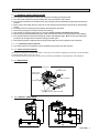
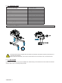
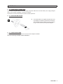
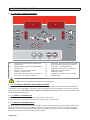
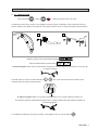
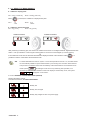
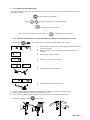
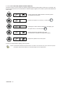
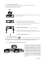
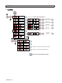
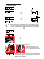
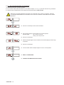
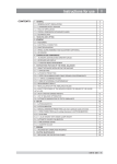
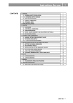
I
INSTRUCTIONS FOR USE
CONTENTS
1 - GENERAL
3
1.1 - GENERAL SAFETY REGULATIONS
3
1.1.1 - STANDARD SAFETY DEVICES
3
1.2 - FIELD OF APPLICATION
3
1.3 - MAIN PARTS
3
1.4 - OVERALL DIMENSIONS
3
1.5 - TECHNICAL DATA
4
2 - HANDLING, LIFTING
4
2.1 - ANCHORING
4
3 - START- UP
5
3.1 - ELECTRICAL CONNECTION
5
3.2 - ADAPTER MOUNTING
5
3.3 - WHEEL MOUNTING
5
4 - CONTROLS AND COMPONENTS
6
4.1 - CONTROL PANEL AND DISPLAY
6
4.2 - AUTOMATIC DISTANCE AND DIAMETER GAUGE
6
4.3 - WHEEL LIFTING DEVICE
6
4.4 - MANUAL SPINNING DEVICE
6
5 - INDICATIONS AND USE OF THE WHEEL BALANCER
7
5.1 - DATA SETTING
7
5.2 - RESULT OF MEASUREMENT
8
5.2.1 - BATTERY CHARGE INDICATION (OPTION)
8
5.2.2 - MODIFYING SET DIMENSIONS
9
5.2.3 - EXACT POSITIONING OF THE ADHESIVE WEIGHT BY MEANS OF THE GAUGE WITH CLIPS
9
5.2.4 - SPLIT FUNCTION (HIDDEN ADHESIVE WEIGHTS)
10
5.2.5 - UNBALANCE OPTIMIZATION
11
5.2.6 - ALU AND STATIC MODES
11
5.2.7 - AUTOMATIC MINIMIZATION OF STATIC UNBALANCE
11
6 - SET UP
12
6.1 - MENU
12
6.2 - AUTOMATIC GAUGES CALIBRATION
13
6.2.1 - RIM DISTANCE GAUGE
13
6.2.2 - DIAMETER GAUGEE40 M
13
6.3 - BALANCING MACHINE CALIBRATION
14
7 - ERRORS
15
7.1 - INCONSISTENT UNBALANCE READINGS
16
8 - ROUTINE MAINTENANCE (SEE EXPLODED DRAWINGS)
16
8.1 - TO REPLACE THE FUSES
16
8.2 - PRECAUTIONS FOR BATTERY USE
16
I 0677 GB
-
1
I 0677 GB
-
2
1 - GENERAL
► 1.1 - GENERAL SAFETY REGULATIONS
■ The machine should only be used by authorized and suitably trained personnel.
■ Do not use the machine for purposes other than those specified in this manual.
■ The machine should not be modified in any way except for those modifications explicitly carried out by
the firm.
■ Never remove the safety devices. Any work on the machine should only be carried out by specialist per
sonnel.
■ Carefully clean the coupling surfaces before performing any operation.
■ Avoid using strong jets of compressed air for cleaning.
■ Use alcohol to clean the plastic panel or shelves (AVOID LIQUIDS CONTAINING SOLVENTS).
■ Before starting the wheel balancing cycle, make sure that the wheel is securely locked on the adapter.
■ The machine operator should avoid wearing clothes with flapping edges. Make sure that unauthorized
personnel do not approach the machine during the work cycle.
■ Avoid placing objects inside the base as they could impair the correct operation of the machine.
► 1.1.1 - STANDARD SAFETY DEVICES
■ The wheel guard is not compulsory since the balancing speed is less than 100 min-1.
► 1.2 - FIELD OF APPLICATION
The machine is designed for balancing wheels of cars and motor vehicles weighing up to 250 kg. It can be operated
in the temperature range of 0°C to + 45°C.
The following functions are provided: ALUM, SPLIT; Unbalance optimization; Self diagnostics; Self calibration.
► 1.3 - MAIN PARTS
LEVA SOLLEVAMENTO
LIFTING LEVER
CALIBRO
AUTOMATIC
AUTOMATICO GAUGE
TASTIERA E
CONTROL
PANEL
DISPLAY
AND DISPLAY
MANDRINO
SHAFT
ASSEMBLY
LEVA DI
LANCIO
SPINNING
LEVER
RUOTE PER
MOVIMENTAZIONE
WHEELS TO
MOVE THE WHEEL BALANCER
► 1.4 - OVERALL DIMENSIONS
I 0677 GB
-
3
► 1.5 - TECHNICAL DATA
Single-phase power supply
12 - 24 V DC 0,15 A
Protection class
IP 54
Balancing speed
70 min-1 TRUCK
Balancing speed
100 min-1 CAR
Cycle time
8-20 seconds
Balancing accuracy
1 gram (car) - 10 grams (truck)
Position resolution
± 0.7°
Average noise
< 70dB (A)
Rim-machine distance
0 - 300 mm
Rim width setting range
1.5” ÷ 20” or 40 ÷ 510 mm
Diameter setting range
10” ÷ 30” or 265 ÷ 765 mm
Max. wheel diameter
1300 mm
2 - HANDLING, LIFTING
THE WHEEL BALANCER MUST BE MOVED USING THE HANDLE AND THE WHEELS AND RAISED BY PRISING ON THE BASE ONLY AT
THE THREE POINTS INDICATED.
NEVER, UNDER ANY CIRCUSTANCE, APPLY FORCE TO OTHER POINTS SUCH AS THE SPINDLE, HEAD, OR ACCESSORY SHELF.
► 2.1 - ANCHORING
The machine can operate on any flat non resilient floor without having to be anchored to the floor. Make sure that the
machine rests on the 3 mounting points provided.
I 0677 GB
-
4
3 - START- UP
► 3.1 - ELECTRICAL CONNECTION
The machine is supplied with an AC power supply and power cable with 12-24 VDC battery. The supply voltage is
given on the machine nameplate. It cannot be changed.
Connection to mains should always be made by expert personnel.
► 3.2 - ADAPTER MOUNTING
3
►
The wheel balancer is supplied complete with cone
type adapter for fastening wheels with central bore.
The threaded terminal is fitted according to the drawing; it can be removed to fit optional adapters.
► 3.3 - WHEEL MOUNTING
The wheels should be fastened with one of the numerous adapters available.
Incorrect centering inevitably causes unbalance.
I 0677 GB
-
5
4 - CONTROLS AND COMPONENTS
► 4.1 - CONTROL PANEL AND DISPLAY
2
1
5
13
6
3
15
3-4
5
6
7
8
6
8
9
12
1-2
10
4
6
16
6
11
14
Digital readouts, AMOUNT OF UNBALANCE,
inside/outside
Digital readouts, POSITION OF UNBALANCE,
inside/outside
Indicators, correction mode selected
Indicators, selection made
Push button, unbalance reading < 5 g (25 oz)
Push button, ounces/grams selection
9
10
11
12
13
14
15
16
7
Push button, selection of mode of correction
SPLIT push button (unbalance resolution)
Push button, FUNCTIONS MENU
Push button, menu selection confirmation
Push button, car/truck selection
HOME Push button
Push buttons, manual dimensions setting
Position repeat
ONLY USE THE FINGERS TO PRESS THE PUSH BUTTONS.
NEVER USE THE COUNTERWEIGHT PINCERS OR OTHER POINTED OBJECTS.
► 4.2 - AUTOMATIC DISTANCE AND DIAMETER GAUGE
This gauge allows measurement of the distance of the wheel from the machine and the wheel diameter at the point
of application of the counterweight. It also allows correct positioning of the counterweights on the inside by using the
specific function (see INDICATION OF EXACT CORRECTION WEIGHT POSITION ) which allows reading the position used
for the measurement within the rim.
► 4.3 - WHEEL LIFTING DEVICE
Allows lifting the wheel from the ground without using a lift in order to spin it.
It also allows lowering the wheel until it touches the ground in order to stop rotation
► 4.4 - MANUAL SPINNING DEVICE
Allows spinning the tyre until when the machine display turns off; this means that the minimum spindle rotation speed
has been reached to perform correct balancing (72’/min. for trucks and 100’/min. for cars). At this point, release the
handle and wait until the unbalance measured appears on the display. If the beep function is enabled (see MENU), a
beep will sound when the correct balancing speed is reached.
I 0677 GB
-
6
5 - USE OF THE WHEEL BALANCER
► 5.1 - DATA SETTING
Press the button
→ balancing machine set in car mode
; LED on
The balancing data is set by means of an "intelligent" automatic gauge; confirmation of the measurement and the
position appear on the display. The round part of the gauge must rest on the rim where the weight will be positioned.
a
b
While the gauge is moving the following appears
when the measurement has been stored
;
.
a) standard weights: When only one measurement is made, the machine interprets the presence of a rim with clipon weight correction
The width value (b) must be set with the buttons
measured with the compass gauge provided.
. The correct measurement is that which can be
b
b) adhesive weights: Make two successive measurements on two correction planes inside the rim.
The balancing machine automatically interprets that the correction will be made with adhesive weights and
the following appears:
For a different combination of the type or position of the weights on the rim, use the button
.
I 0677 GB
-
7
► 5.2 - RESULT OF MEASUREMENT
► Unbalance display pitch:
Car = 1/5 g (.1/0.25 Oz)
is pressed, the unbalance is displayed with pitch:
When
Car =
Truck = 10/50 g (.25/1 Oz)
1g
.1 Oz
Truck = 10 g
.25 Oz
► Unbalance display threshold
Car = 5 g (.4 Oz)
Truck = 50 g (2 Oz)
Inside correction
Outside correction
After performing a balancing spin, the amounts of unbalance are shown on the digital readouts. Digital readouts with
LED’s 3- 4 lit up indicate the correct angular wheel position to mount the counterweights (12 o’clock position).
0
If the unbalance is less than the threshold selected
is displayed instead of the unbalance. With
possible to read the values below the threshold chosen.
NB:
it is
For wheel diameters less than or equal to 13” and at temperatures around 0° C, the wheel balancer automatically initiates a special measurement cycle involving two consutive measurements.
The precision of unbalace values and the reliability of the wheel balancer are unaffected. If the
mobile symbol
should apper at the end of any balancing start operation, turn
the wheel by hand until the unbalance values are displayed. If the battery is low, the symbol
will appear on the screen.
► 5.2.1 - BATTERY CHARGE INDICATION (OPTION)
Displays the battery charge.
To access the function, see MENU MANAGEMENT
Battery low
Battery 50% charged
Battery fully charged or with 12V power supply
I 0677 GB
-
8
► 5.2.2 - MODIFYING SET DIMENSIONS
If the wheel dimensions have been entered incorrectly, the parameters can be modified without repeating the balancing spin by pressing :
access parameter modification →
(select
to modify: (a) distance, (b) width, (d) diameter
→
to obtain the new measurement
or:
pull out the gauge to repeat the measurement →
to obtain the new measurement.
► 5.2.3 - EXACT POSITIONING OF THE ADHESIVE WEIGHT BY MEANS OF THE GAUGE WITH CLIPS
Press the button
if using the correction method with weights on the inside of the rim.
■
■
Fit the correction weight in the specific gauge seat with the adhesive
part facing upwards
Bring the wheel into correct angular position for the plane to be
corrected.
■
Pull the gauge further outwards.
■
Return the gauge to the rest position.
■
INSIDE CORRECTION POSITION
■
OUTSIDE CORRECTION POSITION
■ When the weight application distance has been reached a beep is sounded (can be deactivated).
■ rotate the gauge until the correction weight adheres to the rim
■ the fact that the weight application position is no longer vertical is automatically compensated
■ to cancel this function, press
button again.
I 0677 GB
-
9
► 5.2.4 - SPLIT FUNCTION (HIDDEN ADHESIVE WEIGHTS)
The SPLIT function is used to position the adhesive weights behind the wheel spokes so that they are not visible. This
function should be used in ALU mode where the adhesive weight is applied on the outside. Input the wheel dimensions
and do a spin.
2
1
■ Turn the wheel to the outside unbalance correction position
as indicated by the machine
1
2
■ Position one spoke at 12 o'clock (e.g. 1) and press
2
1
■ Following the rotation direction indicated on the display, position spoke 2 at 12 o'clock and press
1
2
■ Position the wheel as indicated by the LEDs.
The unbalance is indicated on the right-hand display
2
1
■ Repeat the operation for the other spoke
To return to normal unbalance display, press any button.
NOTE: The distance between the spokes must be at least 18° and at most 120° (if not, the errors 24,25 or
26 appear). Spokes with irregular or inconstant angles can be compensated.
I 0677 GB
-
10
► 5.2.5 - UNBALANCE OPTIMIZATION
■ This function serves to reduce the amount of weight to be added in order to balance the wheel.
■ It is suitable for static unbalance exceeding 30 g.
■ It improves the residual eccentricity of the tyre.
■
This operation is required if no unbalance has been measured previously; otherwise go to the next step
■ Mark with chalk a reference point on the adapter and rim.
■ With the aid of a tyre remover, turn the tyre on the rim by 180°.
■ Refit the wheel with the reference mark coinciding between rim and adapter.
■ Perform a manual spin under normal conditions
■ RH display: percentage reduction
■ LH display: actual static unbalance which can be reduced by rotation.
■ Mark the two positions of the rim and tyre, and turn the tyre on the rim
until the positions correspond in order to obtain the optimization on the display.
■ RETURN TO MEASUREMENT SCREEN.
► 5.2.6 - ALU AND STATIC MODES
From the measurement screen, press the
button to select all the possible types of corrections. The (5)-LED
displays show the position where to apply the weights. If a spin has already been performed, the processor automatically recalculates, for each change of mode, the amounts of unbalance according to the new calculation.
► 5.2.7 - AUTOMATIC MINIMIZATION OF STATIC UNBALANCE
Initial unbalance
sx
dx
g
phase shift
g
50°
Possible approximations
sx
sx
dx
g
residual static 4
g
g
sx
dx
g
residual static
g
3g
sx
dx
g
residual static
g
1g
With conventional
Choice with minimum
wheel balancer
static residual
dx
g
residual static
g
6g
This program is designed to improve the quality of
balancing without any mental effort or loss of time by
the operator. In fact by using the normal commercially
available weights, with pitch of 5 in every 5 g, and by
applying the two counterweights which a conventional
wheel balancer rounds to the nearest value, there could
be a residual static unbalance of up to 4 g. The damage
of such approximation is emphasized by the fact that
static unbalance is cause of most of disturbances on
the vehicle. This new function automatically indicates
the optimum entity of the weights to be applied by
approximating them in an “intelligent” way according
to their position in order to minimize residual static
unbalance.
I 0677 GB
-
11
6 - SET UP
► 6.1 - MENU
See chapter on UNBALANCE OPTIMIZATION
diameter unit of
measure mm/inch
width unit of
measure mm/inch
approximates
1-5g or 0.1-.25 oz
approximates
10-50g or .25/1oz
Displays the battery charge values
on/off beep
signal
Calibration of automatic RIM DISTANCE gauge
Calibration of automatic DIAMETER gauge
RETURNS TO MEASUREMENT SCREEN
I 0677 GB
-
12
► 6.2 - AUTOMATIC GAUGES CALIBRATION
► 6.2.1 - RIM DISTANCE GAUGE
■ Leave the distance gauge in rest position
and press
■ Pull out the gauge up to the adapter flange
and press
■ CORRECT CALIBRATION
Return the gauge to rest position.
The wheel balancer is ready for operation.
N.B.:
In the event of errors or faulty operation, the writing “r.P.”: appears on the display : shift the
gauge to the rest position and repeat the calibration operation exactly as described above. If the
error persists, contact the Technical Service Department. In the event of incorrect input in the rim
distance gauge calibration function, press
to cancel it.
E40 m
► 6.2.2 - DIAMETER GAUGE
►
►
►
m
■ Place the round part of the gauge terminal on the flange as shown in the figure
and press
■ The number 8 ± 3° appears on the left display .
■ Turn the gauge downward position the
round part of the gauge terminal at 40 mm
(radial distance) from the flange as indicated
in the figure; alternatively use one of the cones
provided as shown in the images
40
mm
■ The number 289 ± 3° should appear on the left display. The calibration is already correct.
■ If not, press the
button holding the gauge still at 40 mm: the number 289
appears on the left display.
■ Return the gauge to rest position.
I 0677 GB
-
13
► 6.3 - BALANCING MACHINE CALIBRATION
To calibrate the machine, operate as follows:
■ Fit a medium-sized wheel with steel rim on the shaft. Example: 6” x 15” (± 1”) best with less then 20 g unbalance
■ Take the exact measurements of the wheel mounted as described in DATA SETTING.
PRESETTING OF INCORRECT DIMENSIONS WOULD MEAN THAT THE MACHINE IS NOT CORRECTLY CALIBRATED, THEREFORE
ALL SUBSEQUENT MEASUREMENTS WILL BE INCORRECT UNTIL A NEW SELF-CALIBRATION IS PERFORMED WITH THE CORRECT
DIMENSIONS!
■
Perform a manual spin under normal conditions
■
Add a sample weight on the outside in any angular position.
Sample weight:
60 g. (2.00 .oz) for car
300 g. (10.0 .oz) for truck
Perform a manual spin
■
I 0677 GB
-
14
■
Shift the sample weight from the outside to the inside keeping the same angu
lar position.
■
Perform a manual spin
■
Turn the wheel until the sample weight is in the 12 o’clock position
■
END OF CALIBRATION
■
CANCELS CALIBRATION IN ANY PHASE.
7 - ERRORS
During machine operation, various causes of faulty operation could occur. If detected by the microprocessor, they appear
on the display as follows:
ERRORS
CAUSES
CONTROLS
Black
The wheel balancer does not come on.
1.
2.
3.
Check proper connection to the mains.
Check and if necessary replace the fuses on the power board.
Replace the computer board.
Err. 1
No rotation signal.
1.
2.
3.
4.
Check belt tautness.
Check in self-diagnostics that the encoder functions properly.
Replace the phase generator.
Replace the computer board.
Err. 2
Too low speed during measurement.
During the unbalance measurement
revolutions, the wheel speed has fallen to
below 42 rpm.
1.
Check that a vehicle wheel has been mounted on the wheel
balancer.
Check belt tautness.
Check in self-diagnostics that the encoder functions properly.
Replace the computer board.
Too high unbalance.
1.
2.
3.
4.
Err. 3
2.
3.
4.
5.
Err. 4
Check the wheel dimension setting.
Check the sensor connections.
Run the machine calibration function.
Mount a wheel with a more or less known unbalance (less than
100 grams) and check the machine response.
Replace the computer board.
Rotation in opposite direction.
After pressing [START], the wheel
starts turning in the opposite direction
(anticlockwise).
1.
2.
Verify the connection of the UP/DOWN - RESET signals on the
phase encoder.
Check the bearing/spring of the phase generator
Err. 5
Guard open
The [START] pushbutton was pressed
without first closing the guard.
1.
2.
3.
4.
Reset the error.
Close the guard.
Verify the function of the protection uSwitch.
Press the [START] button.
Err. 7 /
Err. 8 /
Err. 9
NOVRAM parameter read error
1.
2.
3.
4.
5.
Repeat machine calibration
Shut down the machine.
Wait for at least ~ 1 min.
Restart the machine and check proper functioning.
Replace the computer board.
Err. 11
Too high speed error.
The average spinning speed is greater than
240 rpm.
1.
2.
3.
Check if there is any damage or dirt on the timing disc.
Check in self-diagnostics that the encoder functions properly
Replace the computer board.
Err.14/
Err.15/
Err.16/
Err.17/
Err. 18/
Err. 19
Unbalance measurement error.
1.
2.
3.
4.
5.
Check functioning of the phase generator.
Check the sensor connections.
Check the machine earthing connection.
Mount a wheel with a more or less known unbalance (less than
100 grams) and check the machine response.
Replace the computer board.
Err.21
Motor on for more than 15 seconds.
1.
2.
3.
Check functioning of the phase generator.
Check the connections on the power board.
Replace the computer board.
Err.22
Maximum number of spins possible for
the unbalance measurement has been
exceeded.
1.
2.
3.
4.
Check that a vehicle wheel has been mounted on the wheel
balancer.
Check belt tautness.
Check in self-diagnostics that the encoder functions properly
Replace the computer board.
Err. 23
The wheel does not slow down
1.
2.
3.
Remember to release the spinning device when the displays go off
Check functioning of the phase generator.
Replace the computer board.
Err. 24
Distance between the spokes smaller
than 18 degrees.
1.
The minimum distance between the spokes where to split the
unbalance must be greater than 18 degrees
Repeat the SPLIT function increasing the distance between the
spokes.
2.
Err. 25
Distance between the spokes greater
than 120 degree
1.
2.
The minimum distance between the spokes where to split the
unbalance must be smaller than 120 degrees
Repeat the SPLIT function increasing the distance between the
spokes.
I 0677 GB
-
15
Err. 26
First spoke too far from unbalance position
1.
2.
Battery low
1.
The minimum distance between the unbalance position and the
spoke must be less than 120 degrees.
Repeat the split function reducing the distance between the
spokes.
Recharge the battery
► 7.1 - INCONSISTENT UNBALANCE READINGS
Sometimes after balancing a wheel and removing it from the balancing machine, it is found that, upon mounting it on
the machine again, the wheel is not balanced. This does not depend on incorrect indication of the machine, but only on
faulty mounting of the wheel on the adapter; i.e. in the two mountings, the wheel has assumed a different position with
respect to the balancing machine shaft centre line. If the wheel has been mounted on the adapter with screws, it could
be possible that the screws have not been correctly tightened, i.e. crosswise one by one, or else (as often occurs) holes
have been drilled on the wheel with too wide tolerances. Small errors, up to 10 grams (0.4 oz) are to be considered
normal in wheels locked by a cone; the error is normally greater for wheels fastened with screws or studs.
If, after balancing, the wheel is found to be still out-of-balance when refitted on the vehicle, this could be due to the
unbalance of the car brake drum or very often due to the holes for the screws on the rim and drum sometimes drilled
with too wide tolerances. In such case a readjustment could be advisable using the balancing machine with the wheel
mounted.
8 - ROUTINE MAINTENANCE (see exploded drawings) (for non specialized personnel only
Switch off the machine from the mains before carrying out any operation.
► 8.1 - TO REPLACE THE FUSES
Remove the weight holder shelf to gain access to the power supply board where the fuses are located (see Exploded
Drawings). If fuses require replacement, use ones of the same current rating.
If the fault persists, contact the Technical Service Department.
► 8.2 - PRECAUTIONS FOR BATTERY USE
To keep the battery efficient over time, do not expose it to direct sunlight, avoid contact with liquids and do not connect the output in short-circuit.
NONE OF THE OTHER MACHINE PARTS REQUIRE MAINTENANCE.
I 0677 GB
-
16