1
General-Purpose Inverter
Varispeed E7
Instruction Manual and
Parameter Description
Model: CIMR-E7C
YEG -TOE-S616-56.1
Contents
Warnings........................................................................................................... i
Safety Precautions and Instructions for Use ................................................... ii
EMC Compatibility .......................................................................................... iv
Electromagnetic Compatibility (EMC).............................................................. v
Registered Trademarks .................................................................................viii
1
Handling Inverters .................................................................. 1-1
Varispeed F7 Introduction.............................................................................1-2
Varispeed F7 Applications .............................................................................................. 1-2
Varispeed F7 Models ...................................................................................................... 1-2
Confirmations upon Delivery ........................................................................1-4
Checks............................................................................................................................ 1-4
Nameplate Information ................................................................................................... 1-4
Component Names......................................................................................................... 1-6
Exterior and Mounting Dimensions...............................................................1-8
Open Chassis Inverters (IP00) ....................................................................................... 1-8
Enclosed Wall-mounted Inverters (NEMA1) ................................................................... 1-8
Checking and Controlling the Installation Site ............................................1-10
Installation Site .............................................................................................................1-10
Controlling the Ambient Temperature ...........................................................................1-10
Protecting the Inverter from Foreign Matter..................................................................1-10
Installation Orientation and Space.............................................................. 1-11
Removing and Attaching the Terminal Cover .............................................1-12
Removing the Terminal Cover ......................................................................................1-12
Attaching the Terminal Cover........................................................................................1-12
Removing/Attaching the Digital Operator and Front Cover ........................1-13
Inverters of 18.5 kW or Less......................................................................................... 1-13
Inverters of 22 kW or More ...........................................................................................1-16
2
Wiring....................................................................................... 2-1
Connections to Peripheral Devices ..............................................................2-2
Connection Diagram .....................................................................................2-3
Circuit Descriptions......................................................................................................... 2-4
Terminal Block Configuration........................................................................2-5
Wiring Main Circuit Terminals .......................................................................2-6
Applicable Wire Sizes and Closed-loop Connectors ...................................................... 2-6
Main Circuit Terminal Functions ...................................................................................2-11
ix
Main Circuit Configurations .......................................................................................... 2-12
Standard Connection Diagrams ................................................................................... 2-13
Wiring the Main Circuits ............................................................................................... 2-14
Wiring Control Circuit Terminals ................................................................. 2-20
Wire Sizes ................................................................................................................... 2-20
Control Circuit Terminal Functions ............................................................................... 2-22
Control Circuit Terminal Connections........................................................................... 2-25
Control Circuit Wiring Precautions ............................................................................... 2-26
Wiring Check.............................................................................................. 2-27
Checks ......................................................................................................................... 2-27
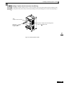
Installing and Wiring Option Cards............................................................. 2-28
Option Card Models and Specifications ....................................................................... 2-28
Installation .................................................................................................................... 2-28
3
Digital Operator and Modes....................................................3-1
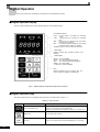
Digital Operator ............................................................................................ 3-2
Digital Operator Display ................................................................................................. 3-2
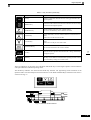
Digital Operator Keys ..................................................................................................... 3-2
Modes .......................................................................................................... 3-4
4
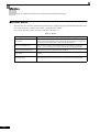
Inverter Modes ............................................................................................................... 3-4
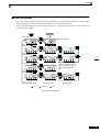
Switching Modes ............................................................................................................ 3-5
Drive Mode ..................................................................................................................... 3-6
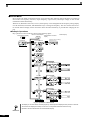
Quick Programming Mode.............................................................................................. 3-7
Advanced Programming Mode....................................................................................... 3-8
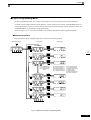
Verify Mode .................................................................................................................. 3-10
Autotuning Mode .......................................................................................................... 3-11
Trial Operation .........................................................................4-1
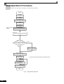
Trial Operation Procedure ............................................................................ 4-2
Trial Operation Procedures .......................................................................... 4-3
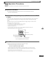
Application Confirmation ................................................................................................ 4-3
Setting the Power Supply Voltage Jumper (400 V Class Inverters of 75 kW or Higher) 4-3
Power ON....................................................................................................................... 4-3
Checking the Display Status .......................................................................................... 4-4
Basic Settings................................................................................................................. 4-5
Selecting the V/f pattern ................................................................................................. 4-7
Autotuning for Line-to-Line Resistance .......................................................................... 4-7
Application Settings ........................................................................................................ 4-9
No-load Operation .......................................................................................................... 4-9
Loaded Operation........................................................................................................... 4-9
Check and Recording User Constants ......................................................................... 4-10
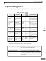
Adjustment Suggestions ............................................................................ 4-11
x
5
User Constants ....................................................................... 5-1
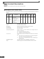
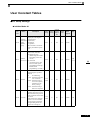
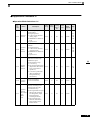
User Constant Descriptions..........................................................................5-2
Description of User Constant Tables .............................................................................. 5-2
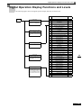
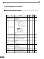
Digital Operation Display Functions and Levels ...........................................5-3
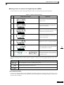
User Constants Settable in Quick Programming Mode .................................................. 5-4
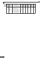
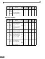
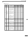
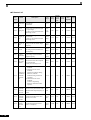
User Constant Tables ...................................................................................5-7
6
A: Setup Settings ............................................................................................................ 5-7
Application Constants: b ................................................................................................. 5-9
Autotuning Constants: C............................................................................................... 5-14
Reference Constants: d ................................................................................................5-17
Motor Constant Constants: E........................................................................................5-19
Option Constants: F......................................................................................................5-20
Terminal Function Constants: H ...................................................................................5-21
Protection Function Constants: L..................................................................................5-26
N: Special Adjustments.................................................................................................5-32
Digital Operator Constants: o .......................................................................................5-33
T: Motor Autotuning ......................................................................................................5-35
U: Monitor Constants ....................................................................................................5-36
Factory Settings that Change with the Inverter Capacity (o2-04) ................................. 5-41
Constant Settings by Function.............................................. 6-1
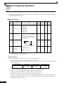
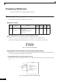
Carrier Frequency Selection.........................................................................6-2
Select the Carrier Frequency suit to the Application....................................................... 6-2
Frequency Reference ...................................................................................6-4
Selecting the Frequency Reference Source ................................................................... 6-4
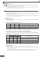
Using Multi-Step Speed Operation ................................................................................. 6-6
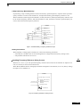
Run Command .............................................................................................6-8
Selecting the Run Command Source ............................................................................. 6-8
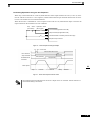
Stopping Methods.......................................................................................6-10
Selecting the Stopping Method when a Stop Command is Input..................................6-10
Using the DC Injection Brake........................................................................................6-13
Using an Emergency Stop ............................................................................................6-14
Acceleration and Deceleration Characteristics...........................................6-15
Setting Acceleration and Deceleration Times ...............................................................6-15
Preventing the Motor from Stalling During Acceleration
(Stall Prevention During Acceleration Function) ...........................................................6-17
Preventing Overvoltage During Deceleration
(Stall Prevention During Deceleration Function)...........................................................6-19
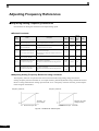
Adjusting Frequency References ...............................................................6-20
Adjusting Analog Frequency References .....................................................................6-20
Operation Avoiding Resonance (Jump Frequency Function) ....................................... 6-22
Speed Limit (Frequency Reference Limit Function) ...................................6-24
Limiting Maximum Output Frequency ...........................................................................6-24
xi
Limiting Minimum Frequency ....................................................................................... 6-24
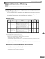
Improved Operating Efficiency ................................................................... 6-25
Compensating for Insufficient Torque at Start and Low-speed Operation
(Torque Compensation)................................................................................................ 6-25
Hunting-prevention Function ........................................................................................ 6-26
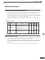
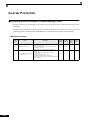
Machine Protection .................................................................................... 6-27
Preventing Motor Stalling During Operation................................................................. 6-27
Detecting Motor Torque ................................................................................................ 6-27
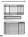
Motor Overload Protection ........................................................................................... 6-30
Motor Overheating Protection Using PTC Thermistor Inputs ....................................... 6-32
Limiting Motor Rotation Direction ................................................................................. 6-33
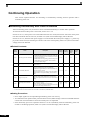
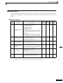
Continuing Operation ................................................................................. 6-34
Restarting Automatically After Power Is Restored ....................................................... 6-34
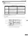
Speed Search............................................................................................................... 6-35
Continuing Operation at Constant Speed When Frequency Reference Is Lost ........... 6-40
Restarting Operation After Transient Error (Auto Restart Function) ............................ 6-41
Inverter Protection ...................................................................................... 6-42
Reducing Inverter Overheating Pre-Alarm Warning Levels ......................................... 6-42
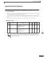
Input Terminal Functions ............................................................................ 6-43
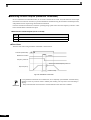
Temporarily Switching Operation between Digital Operator and Control Circuit
Terminals ...................................................................................................................... 6-43
Blocking Inverter Outputs (Baseblock Commands)...................................................... 6-44
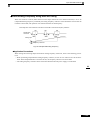
Hold Analog Frequency Using User-set Timing ........................................................... 6-45
Switching Operations between a Communications Option Card and Control Circuit
Terminals...................................................................................................................... 6-46
Jog Frequency Operation without Forward and Reverse Commands
(FJOG/RJOG) .............................................................................................................. 6-46
Stopping the Inverter by Notifying Programming Device Errors to the Inverter
(External Error Function) .............................................................................................. 6-47
Monitor Constants ...................................................................................... 6-48
Using the Analog Monitor Constants............................................................................ 6-48
Individual Functions ................................................................................... 6-50
Using MEMOBUS Communications............................................................................. 6-50
Using PI Control ........................................................................................................... 6-63
Energy-saving .............................................................................................................. 6-70
Setting Motor Constants............................................................................................... 6-71
Setting the V/f Pattern .................................................................................................. 6-72
Digital Operator Functions ......................................................................... 6-78
xii
Setting Digital Operator Functions ............................................................................... 6-78
Copying Constants ....................................................................................................... 6-80
Prohibiting Writing Constants from the Digital Operator............................................... 6-84
Setting a Password ...................................................................................................... 6-84
7
Troubleshooting ..................................................................... 7-1
Protective and Diagnostic Functions ............................................................7-2
Fault Detection................................................................................................................7-2
Alarm Detection .............................................................................................................. 7-7
Operation Errors ............................................................................................................. 7-9
Errors During Autotuning ..............................................................................................7-10
Errors when Using the Digital Operator Copy Function................................................ 7-11
Troubleshooting ..........................................................................................7-12
8
If Constant Constants Cannot Be Set...........................................................................7-12
If the Motor Does Not Operate......................................................................................7-13
If the Direction of the Motor Rotation is Reversed ........................................................ 7-14
If the Motor Does Not Put Out Torque or If Acceleration is Slow ..................................7-15
If the Motor Operates Higher Than the Reference .......................................................7-15
If Motor Deceleration is Slow ........................................................................................7-15
If the Motor Overheats ..................................................................................................7-16
If peripheral devices like PL’s or other are influenced by the
starting or running inverter............................................................................................7-16
If the Ground Fault Interrupter Operates When the Inverter is Run..............................7-17
If There is Mechanical Oscillation .................................................................................7-17
If the Motor Rotates Even When Inverter Output is Stopped........................................7-17
If OV is Detected When the Fan is Started, or Fan Stalls.............................................7-18
If Output Frequency Does Not Rise to Frequency Reference ......................................7-18
Maintenance and Inspection.................................................. 8-1
Maintenance and Inspection.........................................................................8-2
9
Outline of Maintenance................................................................................................... 8-2
Daily Inspection .............................................................................................................. 8-2
Periodic Inspection ......................................................................................................... 8-2
Periodic Maintenance of Parts........................................................................................ 8-3
Cooling Fan Replacement Outline.................................................................................. 8-4
Removing and Mounting the Control Circuit Terminal Card ........................................... 8-6
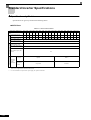
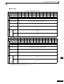
Specifications ......................................................................... 9-1
Standard Inverter Specifications...................................................................9-2
Specifications by Model .................................................................................................. 9-2
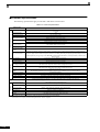
Common Specifications .................................................................................................. 9-4
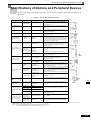
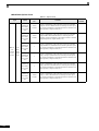
Specifications of Options and Peripheral Devices........................................9-5
10
Appendix ............................................................................... 10-1
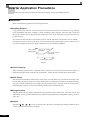
Inverter Application Precautions.................................................................10-2
Selection .......................................................................................................................10-2
Installation..................................................................................................................... 10-3
Settings.........................................................................................................................10-3
Handling........................................................................................................................10-4
xiii
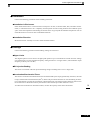
Motor Application Precautions ................................................................... 10-5
Using the Inverter for an Existing Standard Motor ....................................................... 10-5
Using the Inverter for Special Motors ........................................................................... 10-6
Power Transmission Mechanism (Speed Reducers, Belts, and Chains) ..................... 10-6
User Constants .......................................................................................... 10-7
xiv
Warnings
CAUTION
Cables must not be connected or disconnected, nor signal tests carried out, while the power is
switched on.
The VARISPEED E7’s DC bus capacitor remains charged even after the power has been switched
off. To avoid an electric shock hazard, disconnect the frequency inverter from the mains before
carrying out maintenance. Then wait for at least 5 minutes after all LEDs have gone out.
Do not perform a withstand voltage test on any part of the VARISPEED E7. The frequency inverter
contains semiconductors, which are not designed for such high voltages.
Do not remove the digital operator while the mains supply is switched on. The printed circuit board
must also not be touched while the inverter is connected to the power.
Never connect general LC/RC interference suppression filters, capacitors or overvoltage protection
devices to the inverter input or output.
To avoid unnecessary overcurrent faults, etc, being displayed, the signaling contacts of any contactor
or switch fitted between inverter and motor must be integrated into the inverter control logic (eg
baseblock).
This is absolutely imperative!
This manual must be read thoroughly before connecting and operating the inverter. All safety
precautions and instructions for use must be followed.
The inverter may must be operated with the appropriate line filters, following the installation
instructions in this manual and with all covers closed and terminals covered.
Only then will adequate protection be provided. Please do not connect or operate any equipment with
visible damage or missing parts. The operating company is responsible for any injuries or equipment
damage resulting from failure to heed the warnings in this manual.
i
Safety Precautions and Instructions for Use!
1. General
Please read these safety precautions and instructions for use thoroughly before installing and operating this
inverter. Also read all of the warning signs on the inverter and ensure they are never damaged or removed.
Live and hot inverter components may be accessible during operation. Removal of housing components, the
digital operator or terminal covers runs the risk of serious injuries or damage in the event of incorrect installation or operation. The fact that frequency inverters control rotating mechanical machine components can give
rise to other dangers.
The instructions in this manual must be followed. Installation, operation and maintenance may only be carried
out by qualified personnel. For the purposes of the safety precautions, qualified personnel are defined as individuals who are familiar with the installation, starting, operation and maintenance of frequency inverters and
have the proper qualifications for this work. Safe operation of these units is only possible if they are used
properly for their intended purpose.
The DC bus capacitors can remain live from about 5 minutes after the inverter is disconnected from the power.
It is therefore necessary to wait for this time before opening its covers. All of the main circuit terminals may
still carry dangerous voltages.
Children and other unauthorized persons must not be allowed access to these inverters.
Keep these Safety Precautions and Instructions for Use readily accessible and supply them to all persons with
any form of access to the inverters.
2. Intended Use
Frequency inverters are intended for installation in electrical systems or machinery.
Their installation in machinery and systems must conform to the following product standards of the Low Voltage Directive:
EN 50178, 1997-10,
Electronic equipment for use in power installations
EN 60204-1, 1997-12 Safety of machinery – Electrical equiment of machines –
Part 1: General requirements
Attention: plus corrigendum September 1998
EN 61010-1, A2 1995 Safety Requirements for electrical equiment for measurement,
control and laboratory use. Part 1: General requirements
(IEC 950, 1991 + A1, 1992 + A2, 1993 + A3, 1995 + A4, 1996, modified)
CE marking is carried out to EN 50178, using the line filters specified in this manual and following the
appropriate installation instructions.
3. Transportation and storage
The instructions for transportation, storage and proper handling must be followed in accordance with the technical data.
4. Installation
Install and cool the inverters as specified in the documentation. The cooling air must flow in the specified
direction. The inverter may therefore only be operated in the specified position (eg upright). Maintain the
specified clearances. Protect the inverters against impermissible loads. Components must not be bent nor insulation clearances changed. To avoid damage being caused by static electricity, do not touch any electronic
components or contacts.
ii
5. Electrical Connection
Carry out any work on live equipment in compliance with the national safety and accident prevention regulations (eg VBG 4). Carry out electrical installation in compliance with the relevant regulations. For further
information please refer to the User's Manual. In particular, follow the installation instructions ensuring electromagnetic compatibility (EMC), eg shielding, grounding, filter arrangement and laying of cables. This also
applies to equipment with the CE mark. It is the responsibility of the manufacturer of the system or machine to
ensure conformity with EMC limits.
Your supplier or Yaskawa representative must be contacted when using leakage current circuit braker in conjunction with frequency inverters.
In certain systems it may be necessary to use additional monitoring and safety devices in compliance with the
relevant safety and accident prevention regulations. The frequency inverter hardware must not be modified.
6. Notes
The VARISPEED E7 frequency inverters are certified to UL, and c-UL.
iii
EMC Compatibility
1. Introduction
This manual was compiled to help system manufacturers using YASKAWA frequency inverters design and
install electrical switchgear. It also describes the measures necessary to comply with the EMC Directive. The
manual's installation and wiring instructions must therefore be followed.
Our products are tested by authorized bodies using the standards listed below.
Product standard:
EN 61800-3:1996
EN 61000-3-2; A1, A2, A14:2000
2. Measures to Ensure Conformity of YASKAWA Frequency inverters to the EMC Directive
YASKAWA frequency inverters do not necessarily have to be installed in a switch cabinet.
It is not possible to give detailed instructions for all of the possible types of installation. This manual therefore
has to be limited to general guidelines.
All electrical equipment produces radio and line-borne interference at various frequencies. The cables pass
this on to the environment like an aerial.
Connecting an item of electrical equipment (eg drive) to a supply without a line filter can therefore allow HF
or LF interference to get into the mains.
The basic countermeasures are isolation of the wiring of control and power components, proper grounding and
shielding of cables.
A large contact area is necessary for low-impedance grounding of HF interference. The use of grounding
straps instead of cables is therefore definitely advisable.
Moreover, cable shields must be connected with purpose-made ground clips.
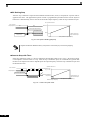
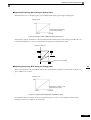
3. Laying Cables
Measures Against Line-Borne Interference:
Line filter and frequency inverter must be mounted on the same metal plate. Mount the two components as
close to each other as possible, with cables kept as short as possible.
Use a power cable with well-grounded shield. Use a shielded motor cable not exceeding 20 meters in length.
Arrange all grounds so as to maximize the area of the end of the lead in contact with the ground
terminal (eg metal plate).
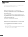
Shielded Cable:
– Use a cable with braided shield.
– Ground the maximum possible area of the shield. It is advisable to ground the shield by connecting the
cable to the ground plate with metal clips (see following figure).
iv
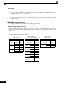
Electromagnetic Compatibility (EMC)
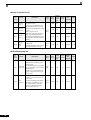
Recommended EMC Filters
Inverter
CIMR-E7C40P4
CIMR-E7C40P7
CIMR-E7C41P5
CIMR-E7C42P2
CIMR-E7C43P7
CIMR-E7C44PO
CIMR-E7C45P5
CIMR-E7C47P5
CIMR-E7C4011
CIMR-E7C4015
CIMR-E7C4018
CIMR-E7C4022
CIMR-E7C4030
CIMR-E7C4037
CIMR-E7C4045
CIMR-E7C4055
CIMR-E7C4075
CIMR-E7C4090
CIMR-E7C4110
Inverter
CIMR-E7C20P4
CIMR-E7C20P7
CIMR-E7C21P5
CIMR-E7C22P2
CIMR-E7C23P7
CIMR-E7C25P5
CIMR-E7C27P5
CIMR-E7C2011
CIMR-E7C2015
CIMR-E7C2018
CIMR-E7C2022
CIMR-E7C2030
CIMR-E7C2037
CIMR-E7C2045
CIMR-E7C2055
Schaffner Filter
Type
Current
Weight
Dimensions
FS5972-10-07
10 A
1,1 kg
141 x 330 x 46
FS5972-18-07
18 A
1,3 kg
141 x 330 x 46
FS5972-35-07
35 A
2,1 kg
206 x 355 x 50
FS5972-60-07
60 A
4 kg
236 x 408 x 65
FS5972-70-52
70 A
3,4 kg
80 x 329 x 185
FS5972-130-35
130 A
4,7 kg
90 x 366 x 180
FS5972-170-40
170 A
6 kg
120 x 451 x 170
FS5972-250-37
250 A
11 kg
130 x 610 x 240
Schaffner Filter
Type
Current
Weight
Dimensions
FS5972-10-07
10 A
1,1 kg
141 x 330 x 46
FS5972-18-07
18 A
1,3 kg
141 x 330 x 46
FS5973-35-07
35 A
1,4 kg
141 x 330 x 46
FS5973-60-07
60 A
3 kg
206 x 355 x 60
FS5973-100-07
100 A
4,9 kg
236 x 408 x 80
FS5973-130-35
130 A
4,3 kg
90 x 366 x 180
FS5973-160-40
160 A
6 kg
120 x 451 x 170
FS5973-240-37
240 A
11 kg
130 x 610 x 240
v
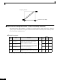
Ground clip
Ground plate
The grounding surfaces must be highly conductive bare metal. Remove any coats of varnish and paint.
– Ground the cable shields at both ends.
– Ground the motor of the machine.
vi
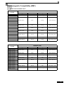
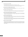
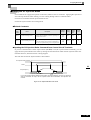
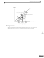
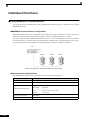
Installation of Boot Type Filters E7C 4022 to 4300
Grounding
Remove any coats of varnish and paint
Metal plate
Cable length
Maximum of 40cm
Motor cable
Length
Maximum of
25m
Grounding
Remove any coats of varnish and paint
vii
Registered Trademarks
The following registered trademarks are used in this manual.
• DeviceNet is a registered trademark of the ODVA (Open DeviceNet Vendors Association,
Inc.).
• InterBus is a registered trademark of Phoenix Contact Co.
• ControlNet is a registered trademark of ControlNet International, Ltd.
• LONworks is a registered trademark of the Echolon.
viii
1
Handling Inverters
This chapter describes the checks required upon receiving or installing an Inverter.
Varispeed E7 Introduction.............................................1-2
Confirmations upon Delivery.........................................1-4
Exterior and Mounting Dimensions...............................1-8
Checking and Controlling the Installation Site ............ 1-11
Installation Orientation and Space..............................1-12
Removing and Attaching the Terminal Cover ............. 1-13
Removing/Attaching the Digital Operator
and Front Cover..........................................................1-14
Varispeed E7 Introduction
Varispeed E7 Applications
The Varispeed E7 is ideal for the following applications.
• Fan, blower, and pump applications
Settings must be adjusted to the application for optimum operation. Refer to Chapter 4 Trial Operation.
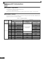
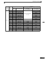
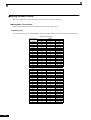
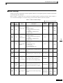
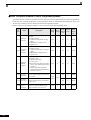
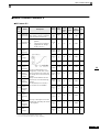
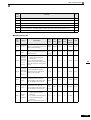
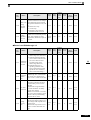
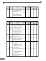
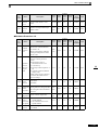
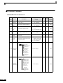
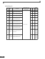
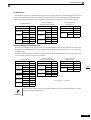
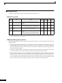
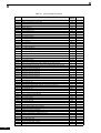
Varispeed E7 Models
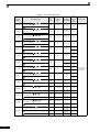
The Varispeed E7 Series of Inverters included two Inverters in two voltage classes: 200 V and 400 V. Maximum motor
capacities vary from 0.4 to 300 kW (42 models).
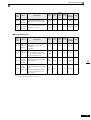
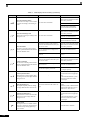
Table 1.1 Varispeed E7 Models
Voltage
Class
200 V class
1-2
Maximum
Motor
Capacity
kW
Varispeed E7
Output
Capacity
kVA
Basic Model Number
Specifications
(Always specify through the protective structure when ordering.)
Open Chassis
(IEC IP00)
CIMR-E7C
Enclosed Wall-mounted
(IEC IP20, NEMA 1)
CIMR-E7C
0.4
1.2
CIMR-E7C20P4
0.75
1.6
CIMR-E7C20P7
20P41
20P71
1.5
2.7
CIMR-E7C21P5
21P51
2.2
3.7
CIMR-E7C22P2
3.7
5.7
CIMR-E7C23P7
5.5
8.8
CIMR-E7C25P5
7.5
12
CIMR-E7C27P5
11
17
CIMR-E7C2011
20111
15
22
CIMR-E7C2015
20151
18.5
27
CIMR-E7C2018
22
32
CIMR-E7C2022
30
44
CIMR-E7C2030
20300
20301
37
55
CIMR-E7C2037
20370
20371
45
69
CIMR-E7C2045
20450
20451
55
82
CIMR-E7C2055
20550
20551
75
110
CIMR-E7C2075
20750
20751
90
130
CIMR-E7C2090
20900
–
110
160
CIMR-E7C2110
21100
–
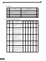
Remove the top and bottom covers from the Enclosed Wallmounted model.
22P21
23P71
25P51
27P51
20220
20181
20221
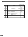
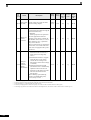
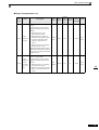
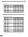
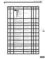
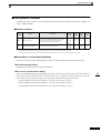
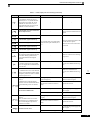
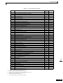
Varispeed E7 Introduction
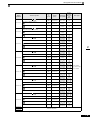
Voltage
Class
400 V class
Maximum
Motor
Capacity
kW
Varispeed E7
Output
Capacity
kVA
Basic Model Number
Specifications
(Always specify through the protective structure when ordering.)
Open Chassis
(IEC IP00)
CIMR-E7C
Enclosed Wall-mounted
(IEC IP20, NEMA 1)
CIMR-E7C
0.4
1.4
CIMR-E7C40P4
40P41
0.75
1.6
CIMR-E7C40P7
40P71
1.5
2.8
CIMR-E7C41P5
2.2
4.0
CIMR-E7C42P2
3.7
5.8
CIMR-E7C43P7
4.0
6.6
CIMR-E7C44P0
5.5
9.5
CIMR-E7C45P5
45P51
7.5
13
CIMR-E7C47P5
47P51
11
18
CIMR-E7C4011
40111
15
24
CIMR-E7C4015
40151
41P51
Remove the top and bottom covers from the Enclosed Wallmount model.
42P21
43P71
44P01
18.5
30
CIMR-E7C4018
22
34
CIMR-E7C4022
30
46
CIMR-E7C4030
40300
40301
37
57
CIMR-E7C4037
40370
40371
45
69
CIMR-E7C4045
40450
40451
55
85
CIMR-E7C4055
40550
40551
75
110
CIMR-E7C4075
40750
40751
90
140
CIMR-E7C4090
40900
40901
110
160
CIMR-E7C4110
41100
41101
132
200
CIMR-E7C4132
41320
41321
160
230
CIMR-E7C4160
41600
41601
185
280
CIMR-E7C4185
41850
–
220
390
CIMR-E7C4220
42200
–
300
510
CIMR-E7C4300
43000
–
40220
40181
40221
1-3
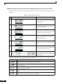
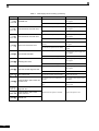
Confirmations upon Delivery
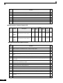
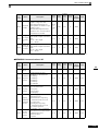
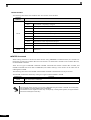
Checks
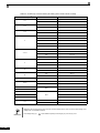
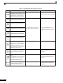
Check the following items as soon as the Inverter is delivered.
Table 1.2 Checks
Item
Method
Has the correct model of Inverter been
delivered?
Check the model number on the nameplate on the side of the Inverter.
Is the Inverter damaged in any way?
Inspect the entire exterior of the Inverter to see if there are any scratches or
other damage resulting from shipping.
Are any screws or other components
loose?
Use a screwdriver or other tools to check for tightness.
If you find any irregularities in the above items, contact the agency from which you purchased the Inverter or
your Yaskawa representative immediately.
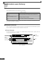
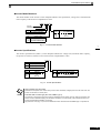
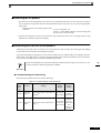
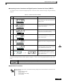
Nameplate Information
There is a nameplate attached to the side of each Inverter. The nameplate shows the model number, specifications, lot number, serial number, and other information on the Inverter.
Example Nameplate
The following nameplate is an example for a standard domestic European Inverter: 3-phase, 200 VAC,
0.4 kW, IEC IP20 and NEMA 1 standards
Inverter
specifications
Inverter model
Input specifications
Output
specifications
Mass
Lot number
Serial number
Fig 1.1 Nameplate
1-4
Confirmations upon Delivery
Inverter Model Numbers
The model number of the Inverter on the nameplate indicates the specification, voltage class, and maximum
motor capacity of the Inverter in alphanumeric codes.
CIMR – E7 C 2 0 P4
Inverter
Varispeed E7
No.
C
Specification
European Standard
No.
2
AC Input, 3-phase, 200 V
4
AC Input, 3-phase, 400 V
No.
0P4
0P7
to
300
Voltage Class
Max. Motor Capacity
0.55 kW
0.75 kW
to
300 kW
“P” Indicates the decimal point.
Fig 1.2 Inverter Model Numbers
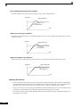
Inverter Specifications
The Inverter specifications (“SPEC”) on the nameplate indicate the voltage class, maximum motor capacity,
the protective structure, and the revision of the Inverter in alphanumeric codes.
2 0P 4 1
Voltage Class
No.
2
AC Input, 3-phase, 200 V
4
AC Input, 3-phase 400 V
No.
0P4
0P7
to
300
Max. Motor Capacity
0.55 kW
0.75 kW
to
300 kW
No.
0
1
Protective Structure
Open chassis (IEC IP00)
Enclosed wall-mounted (IEC IP20,
NEMA Type 1)
“P” Indicates the decimal point
Fig 1.3 Inverter Specifications
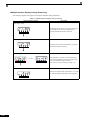
Open Chassis Type (IEC IP00)
Protected so that parts of the human body cannot reach electrically charged parts from the front when the
Inverter is mounted in a control panel.
TERMS
Enclosed Wall-mounted Type (IEC IP20, NEMA Type 1)
The Inverter is structured so that the Inverter is shielded from the exterior, and can thus be mounted to the
interior wall of a standard building (not necessarily enclosed in a control panel). The protective structure conforms to the standards of NEMA 1 in the USA.
Top protective cover (Fig. 1.4) has to be installed to conform with IEG IP20 and NEMA Type 1 requirements.
1-5
Component Names
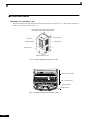
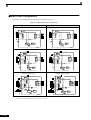
Inverters of 18.5 kW or Less
The external appearance and component names of the Inverter are shown in Fig 1.4. The Inverter with the terminal cover removed is shown in Fig 1.5.
Top protective cover (Part of Enclosed Wallmounted Type (IEC IP20, NEMA Type 1)
Mounting hole
Front cover
Digital Operator
Diecast case
Nameplate
Terminal cover
Bottom protective cover
Fig 1.4 Inverter Appearance (18.5 kW or Less)
Control circuit terminals
Main circuit terminals
Charge indicator
Ground terminal
Fig 1.5 Terminal Arrangement (18.5 kW or Less)
1-6
Confirmations upon Delivery
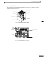
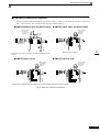
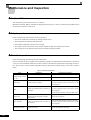
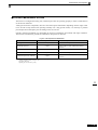
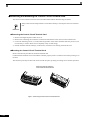
Inverters of 22 kW or More
The external appearance and component names of the Inverter are shown in Fig 1.6. The Inverter with the terminal cover removed is shown in Fig 1.7.
Mounting holes
Inverter cover
Cooling fan
Front cover
Digital Operator
Terminal cover
Nameplate
Fig 1.6 Inverter Appearance (22 kW or More)
Control
circuit
terminals
Charge indicator
Main
circuit
terminals
Ground terminal
Fig 1.7 Terminal Arrangement (22 kW or More)
1-7
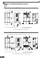
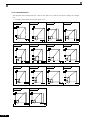
Exterior and Mounting Dimensions
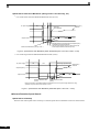
Open Chassis Inverters (IP00)
Exterior diagrams of the Open Chassis Inverters are shown below.
200 V/400 V Class Inverters of 0.4 to 18.5 kW
200 V Class Inverters of 22 or 30 kW
400 V Class Inverters of 22 to 55 kW
Fig 1.8 Exterior Diagrams of Open Chassis Inverters
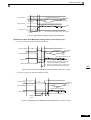
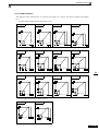
Enclosed Wall-mounted Inverters (NEMA1)
Exterior diagrams of the Enclosed Wall-mounted Inverters (NEMA1) are shown below.
Grommet
200 V/400 V Class Inverters of 0.4 to 18.5 kW
200 V Class Inverters of 22 or 30 kW
400 V Class Inverters of 22 to 55 kW
Fig 1.9 Exterior Diagrams of Enclosed Wall-mounted Inverters
1-8
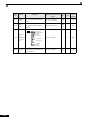
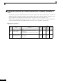
Exterior and Mounting Dimensions
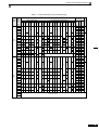
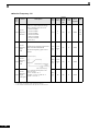
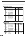
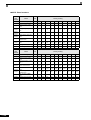
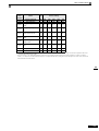
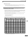
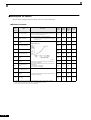
Table 1.3 Inverter Dimensions (mm) and Masses (kg)
Max.
AppliVoltage cable
Class Motor
Output W
[kW]
Caloric
Value(W)
Dimensions (mm)
Open Chassis (IP00)
H
D
W1 H1
H2
D1
Enclosed Wall-mounted (NEMA1)
t1
Approx.
Mass
W
H
D
W1 H0
H1
H2
H3
D1
t1
Approx.
Mass
Mounting
Holes
d*
0.4
20
39
0.75
27
42
50
50
100
129
1.5
2.2
157
140 280
3.7
7.5
11
15
200 V
(3-phase) 18.5
240 350 207 216 335 7.5
275 450
75
375 600
258
300
330
195 385
78
13
450 725 350 325 700
500 850 360 370 820
110
575 885 380 445 855
7
2.3
3.2
140
300
310
350
21
250 535
24
275 615
86
87
4.5
200
240
63
39
126 280 266
7
380
380 890
59
197 186 300 285
10
207 216 350 335 7.5
258
300
330
0
30
195 400 385
135
220 450 435
165
250 600 575
210
13
455 1100 350 325 725 700
108
3
5
0
177
11
57
130
15
140 280
6
100
250 575
157
4
100
220 435
90
3
5
65.5
30
55
7
200 300 197 186 285
250 400
37
126 266
59
22
45
39
177
5.5
305
4
6
65.5
78
2.3
100
3.2
11
69 Natural
70
59
112
74
186
164
84
248
374 170 544
M6
429 183 612
501 211 712
24
586 274 860
27
865 352 1217
62
1015 411 1426
68
1266 505 1771
94
M10
95
---
150
59
219 113 332
7
100
130
M5
1588 619 2207
M12
2437 997 3434
2733 1242 3975
14
39
53
17
41
58
36
48
84
59
56
115
80
68
148
70
91
161
5.5
127
82
209
7.5
193 114 307
0.75
157
39
3
157
39
3
1.5
2.2
3.7
4.0
11
15
18.5
22
30
140 280
126 266
7
177
5
140 280
59
4
75
110
132
160
5
0
59
M5
4
200 300 197 186 285
65.5
6
200 300 197 186 300 285
65.5
6
240 350 207 216 335
78
10
240 350 207 216 350 335
78
10
275 450 258 220 435
7.5
100
2.3
21
275 535 258 220 450 435
36
325
7.5
85
100
2.3
24
105
450 725 350 325 700
13
3.2
130
500 850 360 370 820
575 925 380 445 895
15
88
89
102
4.5 120
140
715
Natural
252 158 410
326 172 498
426 208 634
M6 466 259 725
678 317 995
635
325 550 283 260 535
55
90
7
177
37
45
126 280 266
Fan
2019 838 997
0.4
400 V
(3-phase)
Total Cooling
Heat
Method
Exter InterGennal
nal
eration
Fan
784 360 1144
283 260 550 535
455 1100 350 325 725 700
165
13
105
160 580 1325 380 445 925 895
15
901 415 1316
1203 495 1698
305
3.2
130
505 1245 360 370 850 820
40
395
400 140
96
97
122
M10
1399 575 1974
1614 671 2285
2097 853 2950
4.5 130 M12 2388 1002 3390
170
2791 1147 3938
185
220
Under development
300
* Same for Open Chassis and Enclosed Wall-mounted Inverters.
1-9
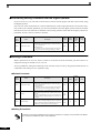
Checking and Controlling the Installation Site
Install the Inverter in the installation site described below and maintain optimum conditions.
Installation Site
Install the Inverter under the following conditions in a pollution degree 2 environment.
Table 1.4 Installation Site
Type
Ambient Operating Temperature
Humidity
Enclosed wall-mounted
-10 to + 40 °C
95% RH or less (no condensation)
Open chassis
-10 to + 45 °C
95% RH or less (no condensation)
Protection covers are attached to the top and bottom of the Inverter. Be sure to remove the protection covers
before installing a 200 or 400 V Class Inverter with an output of 18.5 kW or less in a panel.
Observe the following precautions when mounting the Inverter.
• Install the Inverter in a clean location which is free from oil mist and dust. It can be installed in a totally
enclosed panel that is completely shielded from floating dust.
• When installing or operating the Inverter, always take special care so that metal powder, oil, water, or other
foreign matter does not get into the Inverter.
• Do not install the Inverter on combustible material, such as wood.
• Install the Inverter in a location free from radioactive materials and combustible materials.
• Install the Inverter in a location free from harmful gasses and liquids.
• Install the Inverter in a location without excessive oscillation.
• Install the Inverter in a location free from chlorides.
• Install the Inverter in a location not in direct sunlight.
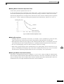
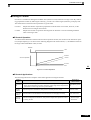
Controlling the Ambient Temperature
To enhance the reliability of operation, the Inverter should be installed in an environment free from extreme
temperature increases. If the Inverter is installed in an enclosed environment, such as a box, use a cooling fan
or air conditioner to maintain the internal air temperature below 45°C.
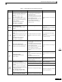
Protecting the Inverter from Foreign Matter
Place a cover over the Inverter during installation to shield it from metal power produced by drilling.
Always remove the cover from the Inverter after completing installation. Otherwise, ventilation will be
reduced, causing the Inverter to overheat.
1-10
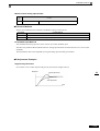
Installation Orientation and Space
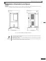
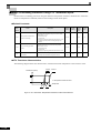
Installation Orientation and Space
Install the Inverter vertically so as not to reduce the cooling effect. When installing the Inverter, always
provide the following installation space to allow normal heat dissipation.
120 mm min.
50 mm min.
Air
30 mm min.
50 mm min.
30 mm min.
120 mm min.
Air
Horizontal Space
Vertical Space
Fig 1.10 Inverter Installation Orientation and Space
IMPORTANT
1. The same space is required horizontally and vertically for both Open Chassis (IP00) and Enclosed Wallmounted (IP20, NEMA 1) Inverters.
2. Always remove the protection covers before installing a 200 or 400 V Class Inverter with an output of
18.5 kW or less in a panel.
Always provide enough space for suspension eye bolts and the main circuit lines when installing a 200 or
400 V Class Inverter with an output of 22 kW or more in a panel.
1-11
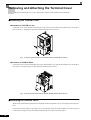
Removing and Attaching the Terminal Cover
Remove the terminal cover to wire cables to the control circuit and main circuit terminals.
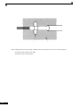
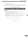
Removing the Terminal Cover
Inverters of 18.5 kW or Less
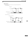
Loosen the screw at the bottom of the terminal cover, press in on the sides of the terminal cover in the directions of arrows 1, and then lift up on the terminal in the direction of arrow 2.
1
2
1
Fig 1.11 Removing the Terminal Cover (Model CIMR-E7C25P5 Shown Above)
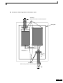
Inverters of 22 kW or More
Loosen the screws on the left and right at the top of the terminal cover, pull out the terminal cover in the direction of arrow 1 and then lift up on the terminal in the direction of arrow 2.
1
2
Fig 1.12 Removing the Terminal Cover (Model CIMR-E7C2022 Shown Above)
Attaching the Terminal Cover
When wiring the terminal block has been completed, attach the terminal cover by reversing the removal procedure.
For Inverters with an output of 18.5 kW or less, insert the tab on the top of the terminal cover into the groove
on the Inverter and press in on the bottom of the terminal cover until it clicks into place.
1-12
Removing/Attaching the Digital Operator and Front Cover
Removing/Attaching the Digital Operator and
Front Cover
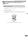
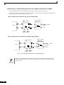
Inverters of 18.5 kW or Less
To attach optional cards or change the terminal card connector, remove the Digital Operator and front cover in
addition to the terminal cover. Always remove the Digital Operator from the front cover before removing the
terminal cover.
The removal and attachment procedures are given below.
Removing the Digital Operator
Press the lever on the side of the Digital Operator in the direction of arrow 1 to unlock the Digital Operator
and lift the Digital Operator in the direction of arrow 2 to remove the Digital Operator as shown in the following illustration.
2
1
Fig 1.13 Removing the Digital Operator (Model CIMR-E7C45P5 Shown Above)
1-13
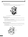
Removing the Front Cover
Press the left and right sides of the front cover in the directions of arrows 1 and lift the bottom of the cover in
the direction of arrow 2 to remove the front cover as shown in the following illustration.
1
2
Fig 1.14 Removing the Front Cover (Model CIMR-E7C45P5 Shown Above)
Mounting the Front Cover
After wiring the terminals, mount the front cover to the Inverter by performing the steps to remove the front
cover in reverse order.
1. Do not mount the front cover with the Digital Operator attached to the front cover; otherwise, Digital
Operator may malfunction due to imperfect contact.
2. Insert the tab of the upper part of the front cover into the groove of the Inverter and press the lower part of
the front cover onto the Inverter until the front cover snaps shut.
Mounting the Digital Operator
After attaching the terminal cover, mount the Digital Operator onto the Inverter using the following procedure.
1. Hook the Digital Operator at A (two locations) on the front cover in the direction of arrow 1 as shown in
the following illustration.
2. Press the Digital Operator in the direction of arrow 2 until it snaps in place at B (two locations).
A
B
1-14
Removing/Attaching the Digital Operator and Front Cover
Fig 1.15 Mounting the Digital Operator
IMPORTANT
1. Do not remove or attach the Digital Operator or mount or remove the front cover using methods other
than those described above, otherwise the Inverter may break or malfunction due to imperfect contact.
2. Never attach the front cover to the Inverter with the Digital Operator attached to the front cover. Imperfect
contact can result.
Always attach the front cover to the Inverter by itself first, and then attach the Digital Operator to the front
cover.
1-15
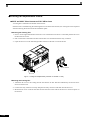
Inverters of 22 kW or More
For Inverter with an output of 22 kW or more, remove the terminal cover and then use the following procedures to remove the Digital Operator and main cover.
Removing the Digital Operator
Use the same procedure as for Inverters with an output of 18.5 kW or less.
Removing the Front Cover
Lift up at the location label 1 at the top of the control circuit terminal card in the direction of arrow 2.
2
1
Fig 1.16 Removing the Front Cover (Model CIMR-E7C2022 Shown Above)
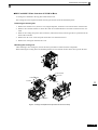
Attaching the Front Cover
After completing required work, such as mounting an optional card or setting the terminal card, attach the
front cover by reversing the procedure to remove it.
1. Confirm that the Digital Operator is not mounted on the front cover. Contact faults can occur if the cover is
attached while the Digital Operator is mounted to it.
2. Insert the tab on the top of the front cover into the slot on the Inverter and press in on the cover until it
clicks into place on the Inverter.
Attaching the Digital Operator
Use the same procedure as for Inverters with an output of 18.5 kW or less.
1-16
2
Wiring
This chapter describes wiring terminals, main circuit terminal connections, main circuit terminal wiring specifications, control circuit terminals, and control circuit wiring specifications.
Connections to Peripheral Devices..............................2-2
Connection Diagram ....................................................2-3
Terminal Block Configuration .......................................2-5
Wiring Main Circuit Terminals ......................................2-6
Wiring Control Circuit Terminals ................................ 2-20
Wiring Check .............................................................2-27
Installing and Wiring Option Cards ............................2-28
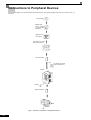
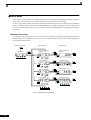
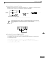
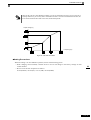
Connections to Peripheral Devices
Examples of connections between the Inverter and typical peripheral devices are shown in Fig 2.1.
Power supply
Molded-case
circuit breaker
or ground fault
interrupter
Magnetic contactor (MC)
AC reactor for power
factor improvement
Input noise filter
DC reactor for power
factor improvement
Inverter
Ground
Output noise filter
Motor
Ground
Fig 2.1 Example Connections to Peripheral Devices
2-2
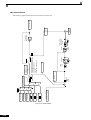
Connection Diagram
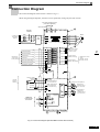
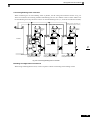
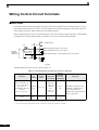
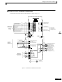
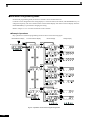
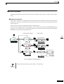
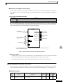
Connection Diagram
The connection diagram of the Inverter is shown in Fig 2.2.
When using the Digital Operator, the motor can be operated by wiring only the main circuits.
DC reactor to improve input
power factor (optional)
Short-circuit bar
Magnetic
Contactor
Fuse
Motor
3-phase power
380 to 480 V
50/60 Hz
Line
Filter
Fault contact output
250 VAC, 1A max.
30 VDC, 1A max.
Forward Run/Stop
Reverse Run/Stop
External fault
Multi-function
contact inputs
Factory setting)
Contact output 1
(Default : Running)
Fault reset
Multi-step speed setting 1
Contact output 2
(Default : Zero speed)
Multi-step speed setting 2
Multi-function contact
output
250 VAC, 1A max.
30 VDC, 1A max.
Jog frequency selection
Shield
terminal
Frequency setting
adjustment
External
frequency
reference
2k ohm
0 to 10V
4 to 20mA
Frequency setting power
+15V, 20mA
Master speed reference
-10 to +10V (20k ohm)
Frequency meter adjustment
Multi-function
analogue output 1
(0 to +10V 2 mA)
Master speed reference
4 to 20 mA (250 ohm)
[0 to +10V (20k ohm)]
Ammeter adjustment
Multi-function
analogue output 2
(0 to +10V 2 mA)
Terminating
resistance
MEMOBUS
communication
RS-485/422
Shielded wires
Twisted-pair
Shielded wires
Fig 2.2 Connection Diagram (Model CIMR-E7C47P5 Shown Above)
2-3
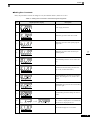
Circuit Descriptions
Refer to the numbers indicated in the diagram on the previous page.
{ These circuits are hazardous and are separated from accessible surfaces by protective separation.
| These circuits are separated from all other circuits by protective separation consisting of double and reinforced insulation. These circuits may be interconnected with SELV (or equivalent) or non-SELV circuits,
but not both.
} Inverter supplied by four-wire-system source (neutral grounded)
These circuits are SELV circuits and are separated from all other circuits by protective separation consisting of double and reinforced insulation. These circuits may only be interconnected with other SELV (or
equivalent) circuits. These circuits can be accessible or interconnected with other accessible SELV circuits.
Inverter supplied by three-wire-system source (ungrounded or corner grounded)
These circuits are not separated from hazardous circuits by protective separation, but only with basic insulation. These circuits cannot be accessed and must not be interconnected with any circuits which are
accessible, unless they are isolated from accessible circuits by supplemental insulation.
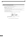
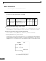
1. Control circuit terminals are arranged as shown below.
IMPORTANT
2. The output current capacity of the +V terminal is 20 mA.
3. Disable the stall prevention during deceleration (set constant L3-04 to 0) when using a Braking Resistor
Unit. If this user constant is not changed to disable stall prevention, the system may not stop within
deceleration time.
4. Main circuit terminals are indicated with double circles and control circuit terminals are indicated with single circles.
5. Sequence input signals S1 to S7 are labeled for sequence connections (0 V common and sinking mode)
for no-voltage contacts or NPN transistors. These are the default settings.
For PNP transistor sequence connections (+24V common and sourcing mode) or to provide a 24-V
external power supply, refer toTable 2.12.
6. The master speed frequency reference can set to input either a voltage (terminal A1) or current (terminal
A2) by changing the setting of parameter H3-13. The default setting is for a voltage reference input.
7. The multi-function analog output is a dedicated meter output for an analog frequency meter, ammeter,
voltmeter, wattmeter, etc. Do not use this output for feedback control or for any other control purpose.
8. DC reactors to improve the input power factor built into 200 V Class Inverters for 22 to 110 kW and 400
V Class Inverters for 22 to 300 kW. The DC reactor is an option for Inverters for 18.5 kW or less.
Remove the short bar when connecting a DC reactor to Inverters for 18.5 kW or less.
Set parameter L8-01 to 1 when using an optional braking resistor unit and braking unit. When using this,
a shutoff sequence for the power supply must be made using a thermal relay trip.
2-4
Terminal Block Configuration
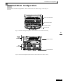
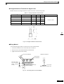
Terminal Block Configuration
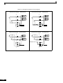
The terminal arrangement for 200 V Class Inverters are shown in Fig 2.3 and Fig 2.4.
Control circuit terminals
Main circuit terminals
Charge indicator
Ground terminal
Fig 2.3 Terminal Arrangement (200 V Class Inverter for 0.4 kW Shown Above)
Control
circuit
terminals
Charge indicator
Main
circuit
terminals
Ground terminal
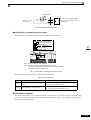
Fig 2.4 Terminal Arrangement (200 V/400 V Class Inverter for 22 kW or more)
2-5
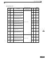
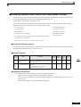
Wiring Main Circuit Terminals
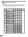
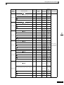
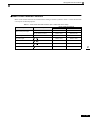
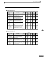
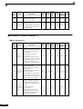
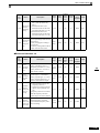
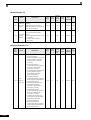
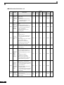
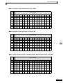
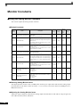
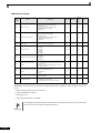
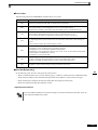
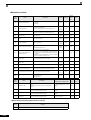
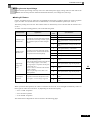
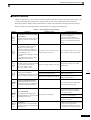
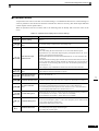
Applicable Wire Sizes and Closed-loop Connectors
Select the appropriate wires and crimp terminals from Table 2.1 to Table 2.3. Refer to instruction manual
TOE-C726-2 for wire sizes for Braking Resistor Units and Braking Units.
Table 2.1 200 V Class Wire Sizes
Inverter
Model
CIMR-
Terminal Symbol
R/L1, S/L2, T/L3,
U/T1, V/T2, W/T3
,
E7C20P4
R/L1, S/L2, T/L3,
U/T1, V/T2, W/T3
,
E7C20P7
R/L1, S/L2, T/L3,
U/T1, V/T2, W/T3
,
E7C21P5
R/L1, S/L2, T/L3,
U/T1, V/T2, W/T3
,
E7C22P2
R/L1, S/L2, T/L3,
U/T1, V/T2, W/T3
,
E7C23P7
R/L1, S/L2, T/L3,
U/T1, V/T2, W/T3
,
E7C25P5
R/L1, S/L2, T/L3,
U/T1, V/T2, W/T3
,
E7C27P5
R/L1, S/L2, T/L3,
U/T1, V/T2, W/T3
,
E7C2011
,
E7C2015
R/L1, S/L2, T/L3,
W/T3
E7C2018
R/L1, S/L2, T/L3,
W/T3
,
1,
1,
1,
1,
1,
1,
1,
1,
1,
1,
2-6
2
(14)
M4
1.2 to 1.5
2 to 5.5
(14 to 10)
2
(14)
M4
1.2 to 1.5
2 to 5.5
(14 to 10)
2
(14)
M4
1.2 to 1.5
2 to 5.5
(14 to 10)
2
(14)
M4
1.2 to 1.5
3.5 to 5.5
(12 to 10)
3.5
(12)
M4
1.2 to 1.5
5.5
(10)
5.5
(10)
M5
2.5
8 to 14
(8 to 6)
8
(8)
M5
2.5
14 to 22
(6 to 4)
14
(6)
M6
4.0 to 5.0
M6
4.0 to 5.0
M8
9.0 to 10.0
M6
4.0 to 5.0
M8
9.0 to 10.0
30
(4)
22
(4)
30
(3)
22
(4)
30
(3)
M6
4.0 to 5.0
M8
9.0 to 10.0
M8
9.0 to 10.0
M6
4.0 to 5.0
M8
9.0 to 10.0
30 to 38
(4 to 2)
22
(4)
30 to 38
(3 to 2)
22
(4)
30 to 60
(3 to 1)
8 to 22
(8 to 4)
22 to 38
(4 to 2)
50 to 60
(1 to 1/0)
8 to 22
(8 to 4)
22 to 38
(4 to 2)
2,
2,
2,
2,
3
3
2 to 5.5
(14 to 10)
2,
R/L1, S/L2, T/L3,
,
1 U/T1,
V/T2, W/T3, R1/L11, S1/L21, T1/L31
E7C2030
1.2 to 1.5
2,
R/L1, S/L2, T/L3,
,
1, U/T1, V/T2,
W/T3, R1/L11, S1/L21, T1/L31
E7C2022
M4
2,
2, U/T1, V/T2,
Recommended
Wire Size
mm2
(AWG)
Tightening
Torque
(N•m)
2,
2, U/T1, V/T2,
Possible
Wire Sizes
Terminal
Screws
mm2(AWG)
22
(4)
50
(1)
22
(4)
Wire Type
Power cables,
e.g., 600 V vinyl
power cables
Wiring Main Circuit Terminals
Inverter
Model
CIMR-
Terminal
Screws
Tightening
Torque
(N•m)
M10
17.6 to 22.5
M8
8.8 to 10.8
M10
17.6 to 22.5
r/l1, ∆/l2
M4
1.3 to 1.4
R/L1, S/L2, T/L3,
,
1 U/T1,
V/T2, W/T3, R1/L11, S1/L21, T1/L31
M10
17.6 to 22.5
M8
8.8 to 10.8
M10
17.6 to 22.5
M4
1.3 to 1.4
M12
31.4 to 39.2
M10
17.6 to 22.5
M8
8.8 to 10.8
M10
17.6 to 22.5
M4
1.3 to 1.4
M12
31.4 to 39.2
M10
17.6 to 22.5
M8
8.8 to 10.8
M10
17.6 to 22.5
M4
1.3 to 1.4
M12
31.4 to 39.2
M12
31.4 to 39.2
M8
8.8 to 10.8
M12
31.4 to 39.2
M4
1.3 to 1.4
M12
31.4 to 39.2
M12
31.4 to 39.2
M8
8.8 to 10.8
M12
31.4 to 39.2
M4
1.3 to 1.4
Terminal Symbol
R/L1, S/L2, T/L3,
,
1 U/T1,
V/T2, W/T3, R1/L11, S1/L21, T1/L31
E7C2037
E7C2045
3
3
r/l1, ∆/l2
R/L1, S/L2, T/L3,
,
1
U/T1, V/T2, W/T3, R1/L11, S1/L21, T1/L31
E7C2055
3
r/l1, ∆/l2
R/L1, S/L2, T/L3,
,
1
U/T1, V/T2, W/T3, R1/L11, S1/L21, T1/L31
E7C2075
3
r/l1, ∆/l2
R/L1, S/L2, T/L3,
,
1
U/T1, V/T2, W/T3, R1/L11, S1/L21, T1/L31
E7C2090
3
r/l1, ∆/l2
R/L1, S/L2, T/L3,
E7C2110
,
1
U/T1, V/T2, W/T3, R1/L11, S1/L21, T1/L31
3
r/l1, ∆/l2
Possible
Wire Sizes
mm2(AWG)
Recommended
Wire Size
mm2
(AWG)
Wire Type
60 to 100
60
(2/0 to 4/0)
(2/0)
5.5 to 22
–
(10 to 4)
30 to 60
30
(2 to 2/0)
(2)
0.5 to 5.5
1.25
(20 to 10)
(16)
80 to 100
80
(3/0 to 4/0)
(3/0)
5.5 to 22
–
(10 to 4)
38 to 60
38
(1 to 2/0)
(1)
0.5 to 5.5
1.25
(20 to 10)
(16)
50 to 100
50 × 2P
(1/0 to 4/0) (1/0 × 2P)
100
100
(4/0)
(4/0)
5.5 to 60
–
(10 to 2/0)
30 to 60
50
(3 to 4/0)
(1/0)
0.5 to 5.5
1.25
(20 to 10)
(16)
80 to 125
80 × 2P
(3/0 to 250) (3/0 × 2P)
80 to 100
80 × 2P
(3/0 to 4/0) (3/0 × 2P) Power cables,
5.5 to 60
e.g., 600 V vinyl
–
(10 to 2/0)
power cables
100 to 200
100
(3/0 to 400)
(3/0)
0.5 to 5.5
1.25
(20 to 10)
(16)
150 to 200
150 × 2P
(250 to 400) (250 × 2P)
100 to 150
100 × 2P
(4/0 to 300) (4/0 × 2P)
5.5 to 60
–
(10 to 2/0)
60 to 150
60 × 2P
(2/0 to 300) (2/0 × 2P)
0.5 to 5.5
1.25
(20 to 10)
(16)
200 × 2P,
or 50 × 4P
200 to 325
(350 × 2P,
(350 to 600)
or 1/0 ×
2P)
150 × 2P,
or 50 × 4P
150 to 325
(300 × 2P,
(300 to 600)
or 1/0 ×
4P)
5.5 to 60
–
(10 to 2/0)
150
150 × 2P
(300)
(300 × 2P)
0.5 to 5.5
1.25
(20 to 10)
(16)
* The wire thickness is set for copper wires at 75°C
2-7
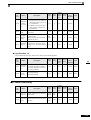
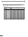
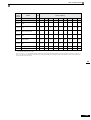
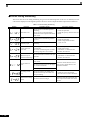
Table 2.2 400 V Class Wire Sizes
Inverter
Model
CIMR-
Terminal Symbol
R/L1, S/L2, T/L3,
U/T1, V/T2, W/T3
,
E7C40P4
R/L1, S/L2, T/L3,
U/T1, V/T2, W/T3
,
E7C40P7
R/L1, S/L2, T/L3,
U/T1, V/T2, W/T3
,
E7C41P5
R/L1, S/L2, T/L3,
U/T1, V/T2, W/T3
,
E7C42P2
R/L1, S/L2, T/L3,
U/T1, V/T2, W/T3
,
E7C43P7
R/L1, S/L2, T/L3,
U/T1, V/T2, W/T3
,
E7C44P0
,
E7C45P5
R/L1, S/L2, T/L3,
U/T1, V/T2, W/T3
R/L1, S/L2, T/L3,
U/T1, V/T2, W/T3
,
E7C47P5
R/L1, S/L2, T/L3,
U/T1, V/T2, W/T3
,
E7C4011
,
E7C4015
R/L1, S/L2, T/L3,
U/T1, V/T2, W/T3
E7C4018
R/L1, S/L2, T/L3,
W/T3
E7C4022
E7C4030
,
1,
1,
1,
1,
1,
1,
1,
1,
1,
1,
1,
2-8
1.2 to 1.5
2 to 5.5
(14 to 10)
2
(14)
M4
1.2 to 1.5
2 to 5.5
(14 to 10)
2
(14)
M4
1.2 to 1.5
2 to 5.5
(14 to 10)
2
(14)
M4
1.2 to 1.5
2 to 5.5
(14 to 10)
2
(14)
M4
1.2 to 1.5
2 to 5.5
(14 to 10)
M4
1.2 to 1.5
2 to 5.5
(14 to 10)
M4
1.2 to 1.5
3.5 to 5.5
(12 to 10)
2 to 5.5
(14 to 10)
M4
1.2 to 1.5
M5
2.5
M5
2.5
M5
(M6)
2.5
(4.0 to 5.0)
M6
4.0 to 5.0
M6
4.0 to 5.0
M6
4.0 to 5.0
M8
9.0 to 10.0
M6
4.0 to 5.0
M8
9.0 to 10.0
M8
9.0 to 10.0
M6
4.0 to 5.0
M8
9.0 to 10.0
2,
2,
mm2 (AWG)
2,
2,
2,
2,
5.5(10)
3.5 to 5.5
(12 to 10)
2,
2, U/T1, V/T2,
R/L1, S/L2, T/L3,
,
1,
3, U/T1, V/T2,
W/T3, R1/L11, S1/L21, T1/L31
R/L1, S/L2, T/L3,
,
1,
3, U/T1, V/T2,
W/T3, R1/L11, S1/L21, T1/L31
3
M4
2,
2,
Recommended
Wire Size
mm2
(AWG)
Tightening
Torque
(N•m)
2,
R/L1, S/L2, T/L3,
,
1, U/T1, V/T2, W/
T3, R1/L11, S1/L21, T1/L31
E7C4037
Possible
Wire Sizes
Terminal
Screws
5.5 to 14
(10 to 6)
8 to 14
(8 to 6)
5.5 to 14
(10 to 6)
8 to 38
(8 to 2)
8 to 22
(8 to 4)
14 to 22
(6 to 4)
14 to 38
(6 to 2)
22
(4)
22 to 38
(4 to 2)
22 to 60
(4 to 1/0)
8 to 22
(8 to 4)
22 to 38
(4 to 2)
3.5
(12)
2
(14)
3.5
(12)
2
(14)
3.5
(12)
2
(14)
5.5
(10)
3.5
(12)
8
(8)
5.5
(10)
8
(8)
5.5
(10)
8
(8)
8
(8)
14
(6)
14
(6)
22
(4)
22
(4)
38
(2)
22
(4)
Wire Type
Power cables,
e.g., 600 V vinyl
power cables
Wiring Main Circuit Terminals
Inverter
Model
CIMR-
Terminal Symbol
R/L1, S/L2, T/L3,
,
1, U/T1, V/T2, W/
T3, R1/L11, S1/L21, T1/L31
E7C4045
3
4.0 to 5.0
M8
9.0 to 10.0
M12
31.4 to 39.2
M10
17.6 to 22.5
M8
8.8 to 10.8
M12
31.4 to 39.2
r/l1, ∆200/l2200, ∆400/l2400
M4
1.3 to 1.4
R/L1, S/L2, T/L3,
M12
31.4 to 39.2
M10
17.6 to 22.5
M8
8.8 to 10.8
M12
31.4 to 39.2
r/l1, ∆200/l2200, ∆400/l2400
M4
1.3 to 1.4
R/L1, S/L2, T/L3,
M12
31.4 to 39.2
M12
31.4 to 39.2
M8
8.8 to 10.8
M12
31.4 to 39.2
r/l1, ∆200/l2200, ∆400/l2400
M4
1.3 to 1.4
R/L1, S/L2, T/L3,
M12
31.4 to 39.2
M12
31.4 to 39.2
M8
8.8 to 10.8
M12
31.4 to 39.2
r/l1, ∆200/l2200, ∆400/l2400
M4
1.3 to 1.4
R/L1, S/L2, T/L3,
M12
31.4 to 39.2
M12
31.4 to 39.2
M8
8.8 to 10.8
M12
31.4 to 39.2
M4
1.3 to 1.4
,
1
3
,
1
3
,
1
3
,
1
U/T1, V/T2, W/T3, R1/L11, S1/L21, T1/L33
3
,
1
U/T1, V/T2, W/T3, R1/L11, S1/L21, T1/L33
E7C4160
4.0 to 5.0
M6
3
U/T1, V/T2, W/T3, R1/L11, S1/L21, T1/L33
E7C4132
M6
9.0 to 10.0
U/T1, V/T2, W/T3, R1/L11, S1/L21, T1/L31
E7C4110
9.0 to 10.0
M8
U/T1, V/T2, W/T3, R1/L11, S1/L21, T1/L31
E7C4090
M8
9.0 to 10.0
R/L1, S/L2, T/L3,
E7C4075
Tightening
Torque
(N•m)
M8
R/L1, S/L2, T/L3,
,
1, U/T1, V/T2,
W/T3, R1/L11, S1/L21, T1/L31
E7C4055
Terminal
Screws
3
r/l1, ∆200/l2200, ∆400/l2400
E7C4185
E7C4220
E7C4300
Possible
Wire Sizes
mm2 (AWG)
38 to 60
(2 to 1/0)
8 to 22
(8 to 4)
22 to 38
(4 to 2)
50 to 60
(1 to 1/0)
8 to 22
(8 to 4)
22 to 38
(4 to 2)
60 to 100
(2/0 to 4/0)
50 to 100
(1/0 to 4/0)
5.5 to 22
(10 to 4)
38 to 60
(2 to 2/0)
0.5 to 5.5
(20 to 10)
80 to 100
(3/0 to 4/0)
80 to 100
(3/0 to 4/0)
8 to 22
(8 to 4)
50 to 100
(1 to 4/0)
0.5 to 5.5
(20 to 10)
50 to 100
(1/0 to 4/0)
50 to 100
(1/0 to 4/0)
8 to 60
(8 to 2/0)
60 to 150
(2/0 to 300)
0.5 to 5.5
(20 to 10)
80 to 100
(3/0 to 4/0)
60 to 100
(2/0 to 4/0)
8 to 60
(8 to 2/0)
100 to 150
(4/0 to 300)
0.5 to 5.5
(20 to 10)
100 to 200
(4/0 to 400)
80 to 200
(3/0 to 400)
80 to 60
(8 to 2/0)
50 to 150
(1/0 to 300)
0.5 to 5.5
(20 to 10)
Recommended
Wire Size
mm2
(AWG)
Wire Type
38
(2)
22
(4)
50
(1)
22
(4)
60
(2/0)
50
(1/0)
38
(2)
1.25
(16)
100
(4/0)
100
(4/0)
50
(1)
1.25
(16)
50 × 2P Power cables,
(1/0 × 2P) e.g., 600 V vinyl
50 × 2P power cables
(1/0 × 2P)
600
(2/0)
1.25
(16)
80 × 2P
(3/0 × 2P)
60 × 2P
(2/0 × 2P)
100
(4/0)
1.25
(16)
100 × 2P
(4/0 × 2P)
80 × 2P
(3/0 × 2P)
50 × 2P
(1/0 × 2P)
1.25
(16)
Under development
* The wire thickness is set for copper wires at 75°C.
2-9
Table 2.3 Closed-loop Connector Sizes (JIS C2805) (200 V Class and 400 V Class)
Wire Thickness (mm2)
Terminal Screws
Size
M3.5
1.25 to 3.5
M4
1.25 to 4
M3.5
1.25 to 3.5
M4
1.25 to 4
M3.5
1.25 to 3.5
M4
1.25 to 4
M3.5
2 to 3.5
M4
2 to 4
M5
2 to 5
M6
2 to 6
M8
2 to 8
M4
5.5 to 4
M5
5.5 to 5
M6
5.5 to 6
M8
5.5 to 8
M5
8 to 5
M6
8 to 6
M8
8 to 8
M6
14 to 6
M8
14 to 8
M6
22 to 6
M8
22 to 8
M8
38 to 8
M8
60 to 8
M10
60 to 10
0.5
0.75
1.25
2
3.5/5.5
8
14
22
30/38
50/60
80
80 to 10
M10
100
100 to 10
100
100 to 12
150
M12
200
150 to 12
200 to 12
M12 x 2
325 to 12
M16
325 to 16
325
Determine the wire size for the main circuit so that line voltage drop is within 2% of the rated voltage. Line
voltage drop is calculated as follows:
Line voltage drop (V) =
IMPORTANT
2-10
3 x wire resistance (W/km) x wire length (m) x current (A) x 10-3
Wiring Main Circuit Terminals
Main Circuit Terminal Functions
Main circuit terminal functions are summarized according to terminal symbols in Table 2.4. Wire the terminals
correctly for the desired purposes.
Table 2.4 Main Circuit Terminal Functions (200 V Class and 400 V Class)
Purpose
Terminal Symbol
Model: CIMR-E7C
200 V Class
400 V Class
R/L1, S/L2, T/L3
20P4 to 2110
40P4 to 4160
R1/L11, S1/L21, T1/L31
2022 to 2110
4022 to 4160
U/T1, V/T2, W/T3
20P4 to 2110
40P4 to 4160
20P4 to 2110
40P4 to 4160
20P4 to 2018
40P4 to 4018
2022 to 2110
4022 to 4160
20P4 to 2110
40P4 to 4160
Main circuit power input
Inverter outputs
DC power input
1,
DC reactor connection
1,
Braking Unit connection
3,
Ground
2
2-11
Main Circuit Configurations
The main circuit configurations of the Inverter are shown in Fig 2.5.
Table 2.5 Inverter Main Circuit Configurations
200 V Class
CIMR-E7C20P4 to 4018
Power
supply
Control
circuits
CIMR-E7C2022, 2030
Power
supply
Control
circuits
CIMR-E7C2037 to 2110
Power
supply
Control
circuits
Note 1. The CIMR-E7C4185 to 4300 Inverters are currently under development.
2. Consult your Yaskawa representative before using 12-phase rectification.
2-12
400 V Class
CIMR-E7C40P4 to 4018
Control
circuits
Power
supply
CIMR-E7C4022 to 4055
Power
supply
Control
circuits
CIMR-E7C4075 to 4160
Power
supply
Control
circuits
Wiring Main Circuit Terminals
Standard Connection Diagrams
Standard Inverter connection diagrams are shown in Fig 2.5. These are the same for both 200 V Class and
400 V Class Inverters. The connections depend on the Inverter capacity.
CIMR-E7C20P4 to 2018 and 40P4 to 4018
CIMR-E7C2022, 2030, and 4022 to 4055
Braking Resistor
Unit (optional)
Braking Resistor
Unit (optional)
Braking Unit
(optional)
Braking Unit
(optional)
DC reactor
(optional)
3-phase 200 VAC
(400 VAC)
3-phase 200
VAC (400 VAC)
The DC reactor is built in.
Be sure to remove the short-circuit bar before connecting the DC
reactor.
CIMR-E7C2037 to 2110
3-phase
200 VAC
CIMR-E7C4075 to 4160
Braking Resistor
Unit (optional)
Braking Resistor
Unit (optional)
Braking Unit
(optional)
Braking Unit
(optional)
3-phase
400 VAC
Control power is supplied internally from the main circuit DC power supply for all Inverter models.
Fig 2.5 Main Circuit Terminal Connections
2-13
Wiring the Main Circuits
This section describes wiring connections for the main circuit inputs and outputs.
Wiring Main Circuit Inputs
Observe the following precautions for the main circuit power supply input.
Installing Fuses
To protect the inverter, it is recommended to use semiconductor fuses like they are shown in the table below.
Table 2.6 Input Fuses
Inverter Type
2-14
Voltage (V)
FUSE
Current (A)
20P4
20P7
21P5
22P2
23P7
25P5
27P5
2011
2015
2018
2022
2030
2037
2045
2055
2075
2090
2110
240
240
240
240
240
240
240
240
240
240
240
240
240
240
240
240
240
240
10
10
15
20
30
40
60
80
100
130
150
180
240
300
350
450
550
600
I2t (A2s)
12~25
12~25
23~55
34~98
82~220
220~610
290~1300
450~5000
1200~7200
1800~7200
870~16200
1500~23000
2100~19000
2700~55000
4000~55000
7100~64000
11000~64000
13000~83000
40P4
40P7
41P5
42P2
43P7
44P0
45P5
47P5
4011
4015
4018
4022
4030
4037
4045
4055
4075
4090
4110
4132
4160
4185
4220
4300
480
480
480
480
480
480
480
480
480
480
480
480
480
480
480
480
480
480
480
480
480
480
480
480
5
5
10
10
15
20
25
30
50
60
70
80
100
125
150
150
250
300
350
400
450
600
700
900
6~55
6~55
10~55
18~55
34~72
50~570
100~570
100~640
150~1300
400~1800
700~4100
240~5800
500~5800
750~5800
920~13000
1500~13000
3000~55000
3800~55000
5400~23000
7900~64000
14000~250000
20000~250000
34000~400000
52000~920000
Wiring Main Circuit Terminals
Installing a Molded-case Circuit Breaker
When connecting the power input terminals (R/L2, S/L2, and T/L3) and power supply via a molded-case circuit breaker (MCCB) observe that the circuit breaker is suitable for the Inverter.
• Choose an MCCB with a capacity of 1.5 to 2 times the Inverter's rated current.
• For the MCCB's time characteristics, be sure to consider the Inverter's overload protection (one minute at
120% of the rated output current).
Installing a Ground Fault Interrupter
Inverter outputs use high-speed switching, so high-frequency leakage current is generated. Therefore, at the
Inverter primary side, use a ground fault interrupter to detect only the leakage current in the frequency range
that is hazardous to humans and exclude high-frequency leakage current.
• For the special-purpose ground fault interrupter for Inverters, choose a ground fault interrupter with a sen-
sitivity amperage of at least 30 mA per Inverter.
• When using a general ground fault interrupter, choose a ground fault interrupter with a sensitivity amper-
age of 200 mA or more per Inverter and with an operating time of 0.1 s or more.
Installing a Magnetic Contactor
If the power supply for the main circuit is to be shut off during a sequence, a magnetic contactor can be used.
When a magnetic contactor is installed on the primary side of the main circuit to forcibly stop the Inverter,
however, the regenerative braking does not work and the Inverter will coast to stop.
• The Inverter can be started and stopped by opening and closing the magnetic contactor on the primary side.
Frequently opening and closing the magnetic contactor, however, may cause the Inverter to break down.
Start and stop the Inverter at most once every 30 minutes.
• When the Inverter is operated with the Digital Operator, automatic operation cannot be performed after
recovery from a power interruption.
• If a Braking Unit and a Braking Resistor Unit are used, program the sequence so that the magnetic contac-
tor is turned OFF by the contact of the Braking Resistor Unit's thermal overload relay.
Connecting Input Power Supply to the Terminal Block
Input power supply can be connected to any terminal R, S or T on the terminal block; the phase sequence of
input power supply is irrelevant to the phase sequence.
Installing an AC Reactor
If the Inverter is connected to a large-capacity power transformer (600 kW or more) or the phase advancing
capacitor is switched, an excessive peak current may flow through the input power circuit, causing the converter unit to break down.
To prevent this, install an optional AC Reactor on the input side of the Inverter or a DC reactor to the DC reactor connection terminals (for units from 22 kW the DC reactor is standard).
This also improves the power factor on the power supply side.
Installing a Surge Absorber
Always use a surge absorber or diode for inductive loads near the Inverter. These inductive loads include magnetic contactors, electromagnetic relays, solenoid valves, solenoids, and magnetic brakes.
Wiring the Output Side of Main Circuit
Observe the following precautions when wiring the main output circuits.
2-15
Connecting the Inverter and Motor
Connect output terminals U/T1, V/T2, and W/T3 to motor lead wires U, V, and W.
Check that the motor rotates forward with the forward run command. Switch over any two of the output terminals to each other and reconnect if the motor rotates in reverse with the forward run command.
Never Connect a Power Supply to Output Terminals
Never connect a power supply to output terminals U/T1, V/T2, and W/T3. If voltage is applied to the output
terminals, the internal circuits of the Inverter will be damaged.
Never Short or Ground Output Terminals
If the output terminals are touched with bare hands or the output wires come into contact with the Inverter casing, an electric shock or grounding will occur. This is extremely hazardous. Do not short the output wires.
Do Not Use a Phase Advancing Capacitor or Noise Filter
Never connect a phase advancing capacitor or LC/RC noise filter to an output circuit. The high-frequency
components of the Inverter output may result in overheating or damage to these part or may result in damage
to the Inverter or cause other parts to burn.
Do Not Use an Electromagnetic Switch
Never connect an electromangetic switch (MC) between the Inverter and motor and turn it ON or OFF during
operation. If the MC is turned ON while the Inverter is operating, a large inrush current will be caused and the
overcurrent protection in the Inverter will operate.
When using an MC to switch to a commercial power supply, stop the Inverter and motor before operating the
MC. Use the speed search function if the MC is operated during operation. If measures for momentary power
interrupts are required, use a delayed release MC.
Installing a Thermal Overload Relay
This Inverter has an electronic thermal protection function to protect the motor from overheating. If, however,
more than one motor is operated with one Inverter or a multi-polar motor is used, always install a thermal
relay (THR) between the Inverter and the motor and set L1-01 to 0 (no motor protection). The sequence
should be designed so that the contacts of the thermal overload relay turn OFF the magnetic contactor on the
main circuit inputs.
2-16
Wiring Main Circuit Terminals
Cable Length between Inverter and Motor
If the cable between the Inverter and the motor is long, the high-frequency leakage current will increase, causing the Inverter output current to increase as well. This may affect peripheral devices. To prevent this, adjust
the carrier frequency (set in C6-02) as shown in Table 2.7. (For details, refer to Chapter 5 User Constants.)
Table 2.7 Cable Length between Inverter and Motor
Cable length
50 m max.
100 m max.
More than 100 m
Carrier frequency
15 kHz max.
10 kHz max.
5 kHz max.
Ground Wiring
Observe the following precautions when wiring the ground line.
• Always use the ground terminal of the 200 V Inverter with a ground resistance of less than 100 Ω and that
of the 400 V Inverter with a ground resistance of less than 10 Ω.
• Do not share the ground wire with other devices, such as welding machines or power tools.
• Always use a ground wire that complies with technical standards on electrical equipment and minimize the
length of the ground wire.
Leakage current flows through the Inverter. Therefore, if the distance between the ground electrode and the
ground terminal is too long, potential on the ground terminal of the Inverter will become unstable.
• When using more than one Inverter, be careful not to loop the ground wire.
OK
NO
Fig 2.6 Ground Wiring
2-17
Connecting an optional Braking Resistor Unit (LKEB) and Braking Unit (CDBR)
Connect the Braking Resistor Unit and Braking Unit to the Inverter as shown in the Fig 2.7.
To prevent the Unit from overheating, design the sequence to turn OFF the power supply for the thermal overload relay trip contacts of the Unit as shown in Fig 2.7.
200 V and 400 V Class Inverters with 0.4 to 18.5 kW Output
CDBR Braking
Unit
LKEB Braking
Resistor Unit
1
Thermal
protector
trip contact
Inverter
Thermal overload
relay trip contact
200 V and 400 V Class Inverters with 22 kW or higher Output
CDBR Braking
Unit
LKEB Braking
Resistor Unit
Thermal
protector
trip contact
Inverter
Thermal overload
relay trip contact
Fig 2.7 Connecting the Braking Resistor Unit and Braking Unit
When using an optional Braking Unit and Braking Resistor Unit, the parameter L3-04 (Stall prevention
selection during deceleration) has to be set to 0. Otherwise stall prevention is enabled and the Braking
Unit will not work.
IMPORTANT
2-18
Wiring Main Circuit Terminals
Connecting Braking Units in Parallel
When connecting two or more Braking Units in parallel, use the wiring and connectors shown in Fig 2.8.
There are connectors for selecting whether each Braking Unit is to be a Master or Slave. Select “Master” for
the first Braking Unit only, and select “Slave” for all other Braking Units (i.e., from the second Unit onwards).
Braking resistor overheating contacts (Thermal protector contacts)
Braking resistor overheating contacts (Thermal protector contacts)
Braking
Resistor
Unit
Braking
Resistor
Unit
Level
detector
Braking
Resistor
Unit
Inverter
Braking resistor overheating contacts (Thermal protector contacts)
Braking Unit #2
Braking Unit #3
Cooling fin overheating contacts (thermostatic contacts)
Cooling fin overheating contacts (thermostatic contacts)
Braking Unit #1
Cooling fin overheating contacts (thermostat contacts)
Fig 2.8 Connecting Braking Units in Parallel
Breaking Unit Application Precautions
When using a Braking Resistor Unit, create a sequence to detect overheating of the braking resistor.
2-19
Wiring Control Circuit Terminals
Wire Sizes
For remote operation using analog signals, keep the control line length between the Analog Operator or operation signals and the Inverter to 50 m or less, and separate the lines from high-power lines (main circuits or
relay sequence circuits) to reduce induction from peripheral devices.
When setting frequencies from an external frequency setter (and not from a Digital Operator), used shielded
twisted-pair wires and ground the shield to terminal E (G), as shown in the following diagram.
E (G)
Shield terminal
2 kΩ
Speed setting power supply, +15 V 20 mA
2 kΩ
External
frequency
reference
0 to +10 V
Master speed reference, 0 to +10 V (20 kΩ)
4 to 20 mA
Master speed reference, 4 to 20 mA (250 Ω)/0 to +10 V (20 kΩ)
Fig 2.9
Terminal numbers and wire sizes are shown in Table 2.8.
Table 2.8 Terminal Numbers and Wire Sizes (Same for all Models)
Terminals
Terminal
Screws
Tightening
Torque
(N•m)
Possible
Wire Sizes
mm2(AWG)
Recommended
Wire Size
mm2(AWG)
0.75
(18)
1.25
(12)
FM, AC, AM, SC, A1,
A2, +V, –V, S1, S2, S3,
S4, S5, S6, S7
MA, MB, MC, M1, M2,
M3, M4
R+, R-, S+, S-, IG
Phoenix
type
0.5 to 0.6
Single wire*3:
0.14 to 2.5
Stranded
wire:
0.14 to 1.5
(26 to 14)
E (G)
M3.5
0.8 to 1.0
0.5 to 2*2
(20 to 14)
Wire Type
• Shielded, twisted-pair wire*1
• Shielded, polyethylene-covered, vinyl sheath cable
(KPEV-S by Hitachi Electrical
Wire or equivalent)
* 1. Use shielded twisted-pair cables to input an external frequency reference.
* 2. Refer to Table 2.3 Close-loop Connector Sizes for suitable closed-loop crimp terminal sizes for the wires.
* 3. We recommend using straight solderless terminal on signal lines to simplify wiring and improve reliability.
2-20
Wiring Control Circuit Terminals
Straight Solderless Terminals for Signal Lines
Models and sizes of straight solderless terminal are shown in the following table.
Table 2.9 Straight Solderless Terminal Sizes
Model
d1
d2
L
0.25 (24)
AI 0.25 - 8YE
0.8
2
12.5
0.5 (20)
AI 0.5 - 8WH
1.1
2.5
14
0.75 (18)
AI 0.75 - 8GY
1.3
2.8
14
1.25 (16)
AI 1.5 - 8BK
1.8
3.4
14
2 (14)
AI 2.5 - 8BU
2.3
4.2
14
Manufacturer
Phoenix Contact
L
Wire Size mm2 (AWG)
Fig 2.10 Straight Solderless Terminal Sizes
Wiring Method
Use the following procedure to connect wires to the terminal block.
1. Loosen the terminal screws with a thin-slot screwdriver.
2. Insert the wires from underneath the terminal block.
3. Tighten the terminal screws firmly.
Thin-slot screwdriver
Blade of screwdriver
Control circuit
terminal block
Strip the end for
7 mm if no solderless terminal
is used.
Solderless terminal or wire
without soldering
Wires
3.5 mm max.
Blade thickness: 0.6 mm max.
Fig 2.11 Connecting Wires to Terminal Block
2-21
Control Circuit Terminal Functions
The functions of the control circuit terminals are shown in Table 2.10. Use the appropriate terminals for the
correct purposes.
Table 2.10 Control Circuit Terminals
Type
No.
S1
Signal Name
Forward run/stop command
Function
Forward run when ON; stopped when OFF.
S2
Reverse run/stop command
Reverse run when ON; stopped when OFF.
S3
Sequence
input
signals
Analog
input
signals
*
Fault when ON.
Reset when ON
S4
Fault reset
S5
Multi-step speed reference
1*1
(Master/auxiliary switch)
Auxiliary frequency reference when ON.
S6
Multi-step speed reference
2*1
Multi-step setting 2 when
ON.
S7
Jog frequency reference*1
Jog frequency when ON.
SC
Sequence input common
+V
15 V power output
15 V power supply for analog references
15 V
(Max. current: 20 mA)
–V
–15 V power output
not used
–15 V
(Max. current: 20 mA)
A1
Frequency reference
0 to +10 V/100%
0 to +10 V(20 kΩ)
A2
Multi-function analog input
4 to 20 mA/100%
0 to +10 V/100%
AC
Analog reference common
–
–
Shield wire, optional ground
line connection point
–
–
E(G)
M1
M2
Sequence
output
signals
External fault input
*1
Running signal
(1NO contact)
Functions are
selected by setting H1-01 to
H1-05.
–
Function is
selected by setting H3-09.
Operating when ON.
Multi-function
contact outputs
M3
Zero speed
Zero level (b2-01) or
below when ON
Fault output signal (SPDT)
Fault when CLOSED across MA and MC
Fault when OPEN across MB and MC
M4
MB
MC
FM
Multi-function analog output 0 to +10 V/100% fre(frequency output)
quency
AC
Analog common (copy)
AM
Multi-function analog output 5 V/Inverter's rated cur(current monitor)
rent
R+
RS485/
422
RS+
MEMOBUS communications input
S-
MEMOBUS communications output
IG
Signal common
24 VDC, 8 mA
Photocoupler isolation
–
MA
Analog
output
signals
Signal Level
4 to 20 mA(250Ω)
0 to +10 V(20kΩ)
Dry contacts
Contact capacity:
1 A max. at 250 VAC
1 A max. at 30 VDC
Dry contacts
Contact capacity:
1 A max. at 250 VAC
1 A max. at 30 VDC
Multi-function
analog monitor 1
0 to +10 V max. ±5%
2 mA max.
–
Multi-function
analog monitor 2
For 2-wire RS-485, short R+ and S+ as well
as R- and S-.
-
Differential input, PHC
isolation
Differential input, PHC
isolation
-
* 1. The default settings are given for terminals S3 to S7. For a 3-wire sequence, the default settings are a 3-wire sequence for S5, multi-step speed setting 1
for S6 and multi-step speed setting 2 for S7.
* 2. When driving a reactive load, such as a relay coil with DC power supply, always insert a flywheel diode as shown in Fig 2.12.
2-22
Wiring Control Circuit Terminals
Flywheel diode
The rating of the flywheel diode
must be at least as high as the
circuit voltage.
Coil
External power:
30 VDC max.
1 A max.
Fig 2.12 Flywheel Diode Connection
DIP Switch S1 and Shunt Connector CN15
The DIP switch S1 and shunt connector CN 15 are described in this section.
S1
OFF ON
I
V
CN15
Terminating resistance*
Analog input A2 switch
: Factory settings
Analog output switch**
Voltage output
Current output
S1
CN15
* Note: Refer to Table 2.11 for S1 functions .
**Note: CN15 is not available at the standard terminal board.
An optional terminal board with CN15 Shunt Connector is available.
The standard setting is voltage output.
Fig 2.13 DIP Switch S1 and Shunt Connector CN15
The functions of DIP switch S1 are shown in the following table.
Table 2.11 DIP Switch S1
Name
Function
Setting
S1-1
RS-485 and RS-422 terminating resistance
OFF: No terminating resistance
ON: Terminating resistance of 110 Ω
S1-2
Input method for analog input A2
OFF: 0 to 10 V (internal resistance: 20 kΩ)
ON: 4 to 20 mA (internal resistance: 250 Ω)
Sinking/Sourcing Mode
The input terminal logic can be switched between sinking mode (0-V common) and sourcing mode (+24V
common) by using the terminals SN, SC, and SP. An external power supply is also supported, providing more
freedom in signal input methods.
2-23
Table 2.12 Sinking/Sourcing Mode and Input Signals
Internal Power Supply – Sinking Mode
External Power Supply – Sinking Mode
External +24V
Internal Power Supply – Sourcing Mode
External Power Supply – Sourcing Mode
External +24V
2-24
Wiring Control Circuit Terminals
Control Circuit Terminal Connections
Connections to Inverter control circuit terminals are shown in Fig 2.14.
Fault contact output
250 VAC, 1A max.
30 VDC, 1A max.
Forward Run/Stop
Reverse Run/Stop
Multi-function
contact inputs
(Factory
setting)
External fault
Contact output 1
(Default : Running)
Fault reset
Multi-step speed setting 1
Contact output 2
(Default : Zero speed)
Multi-step speed setting 2
Multi-function
contact output
250 VAC, 1A max
30 VDC, 1A max
Jog frequency selection
Shield
terminal
Frequency setting
adjustment
External
frequency
reference
2k ohm
0 to 10V
4 to 20mA
Shield
terminal
Frequency setting power
+15V, 20mA
Master speed reference
-10 to +10V (20k ohm)
Frequency meter adjustment
Multi-function
analogue output 1
(-10 to +10V 20mA)
[Default: Output
frequency 0 to +10V]
Ammeter adjustment
Multi-function
analogue output 2
(0 to +10V 20mA)
[Default: Output
frequency 0 to +10V]
Master speed reference
4 to 20 mA (250 ohm)
[0 to +10V (20 k ohm)]
Terminating
resistance
MEMOBUS
communication
RS-485/422
Shielded wires
Twisted-pair
Shielded wires
Fig 2.14 Control Circuit Terminal Connections
2-25
Control Circuit Wiring Precautions
Observe the following precautions when wiring control circuits.
• Separate control circuit wiring from main circuit wiring (terminals R/L1, S/L2, T/L3, U/T1, V/T2, W/T3,
,
1,
2, and
3) and other high-power lines.
• Separate wiring for control circuit terminals MA, MB, MC, M1, M2, M3 and M4 (contact outputs) from
wiring to other control circuit terminals.
• If using an optional external power supply, it shall be a UL Listed Class 2 power supply source.
• Use twisted-pair or shielded twisted-pair cables for control circuits to prevent operating faults. Process
cable ends as shown in Fig 2.15.
• Connect the shield wire to terminal E (G).
• Insulate the shield with tape to prevent contact with other signal lines and equipment.
Shield sheath
Armor
Do not connect here.
Connect to shield sheath terminal at Inverter (terminal E Insulate with tape
(G))
Fig 2.15 Processing the Ends of Twisted-pair Cables
2-26
Wiring Check
Wiring Check
Checks
Check all wiring after wiring has been completed. Do not perform a buzzer check on control circuits. Perform
the following checks on the wiring.
• Is all wiring correct?
• Have any wire clippings, screws, or other foreign material been left?
• Are all screws tight?
• Are any wire ends contacting other terminals?
2-27
Installing and Wiring Option Cards
Option Card Models and Specifications
One Option Card can be mounted in the Inverter as shown in Fig 2.16.
Table 2.13 lists the type of Option Cards and their specifications.
Table 2.13 Option Card and their Specifications
Card
Model
Specifications
Mounting Location
DeviceNet Communications
Card
SI-N
DeviceNet communications support
C
Profibus-DP Communications Card
SI-P
Profibus-DP communications support
C
InterBus-S Communications
Card
SI-R
InterBus-S communications support
C
Installation
Before mounting an Option Card, remove the terminal cover and be sure that the charge indicator inside the
Inverter is not lit. After confirming that the charge indicator is not lit, remove the Digital Operator and front
cover and then mount the Option Card.
Refer to documentation provided with the Option Card for actual mounting instructions for option slot C.
2-28
Installing and Wiring Option Cards
Preventing C Option Card Connectors from Rising
After installing an Option Card into slot C, insert an Option Clip to prevent the side with the connector from
rising. The Option Clip can be easily removed by holding onto the protruding portion of the Clip and pulling it
out.
CN2
C Option Card connector
C Option Card mounting spacer
C Option Card
Option clip
(to prevent raising of
C Option Card)
Fig 2.16 Mounting Option Cards
2-29
2-30
3
Digital Operator and Modes
This chapter describes Digital Operator displays and functions, and provides an overview of
operating modes and switching between modes.
Digital Operator............................................................3-2
Modes ..........................................................................3-4
Digital Operator
This section describes the displays and functions of the Digital Operator.
Digital Operator Display
The key names and functions of the Digital Operator are described below.
Drive Mode Indicators
FWD:
Lit when there is a forward run command
input.
REV:
Lit when there is a reverse run command
input.
SEQ:
Lit when the run command from the control
circuit terminal is enabled.
REF:
Lit when the frequency reference from control
circuit terminals A1 and A2 is enabled.
ALARM: Lit when an error or alarm has occurred.
Data Display
Displays monitor data, constant numbers, and
settings.
Mode Display
DRIVE: Lit in Drive Mode.
QUICK: Lit in Quick Programming Mode.
ADV:
Lit in Advanced Programming Mode.
VERIFY: Lit in Verify Mode.
A. TUNE:Lit in Autotuning Mode.
Keys
Execute operations such as setting user constants, monitoring, jogging, and autotuning.
Fig 3.1 Digital Operator Component Names and Functions
Digital Operator Keys
The names and functions of the Digital Operator Keys are described in Table 3.1.
Table 3.1 Key Functions
Key
3-2
Name
Function
LOCAL/REMOTE Key
Switches between operation via the Digital Operator (LOCAL) and
control circuit terminal operation (REMOTE).
This Key can be enabled or disabled by setting user constant o2-01.
MENU Key
Selects menu items (modes).
ESC Key
Returns to the status before the DATA/ENTER Key was pressed.
Digital Operator
Table 3.1 Key Functions (Continued)
Key
Name
Function
JOG Key
Enables jog operation when the Inverter is being operated from the
Digital Operator.
FWD/REV Key
Selects the rotation direction of the motor when the Inverter is being
operated from the Digital Operator.
Shift/RESET Key
Sets the number of digits for user constant settings.
Also acts as the Reset key when a fault has occurred.
Increment Key
Selects menu items, sets user constant numbers, and increments set
values.
Used to move to the next item or data.
Decrement Key
Selects menu items, sets user constant numbers, and decrements set
values.
Used to move to the previous item or data.
DATA/ENTER Key
Pressed to enter menu items, user constants, and set values.
Also used to switch from one screen to another.
RUN Key
Starts the Inverter operation when the Inverter is being controlled by
the Digital Operator.
STOP Key
Stops Inverter operation.
This Key can be enabled or disabled when operating from the control
circuit terminal by setting user constant o2-02.
Note Except in diagrams, Keys are referred to using the Key names listed in the above table.
There are indicators on the upper left of the RUN and STOP Keys on the Digital Operator. These indicators
will light and flash to indicate operating status.
The RUN Key indicator will flash and the STOP Key indicator will light during initial excitation of the
dynamic brake. The relationship between the indicators on the RUN and STOP Keys and the Inverter status is
shown in the Fig 3.2.
Fig 3.2 RUN and STOP Indicators
3-3
Modes
This section describes the Inverter's modes and switching between modes.
Inverter Modes
The Inverter's user constants and monitoring functions are organized in groups called modes that make it easier to read and set user constants.The Inverter is equipped with 5 modes.
The 5 modes and their primary functions are shown in the Table 3.2.
Table 3.2 Modes
Mode
Drive mode
Quick programming mode
Use this mode to reference and set the minimum user constants to operate the
Inverter (e.g., the operating environment of the Inverter and Digital Operator).
Advanced programming mode
Use this mode to reference and set all user constants.
Verify mode
Use this mode to read/set user constants that have been changed from their factoryset values.
Autotuning mode
3-4
Primary function(s)
The Inverter can be run in this mode.
Use this mode when monitoring values such as frequency references or output current, displaying fault information, or displaying the fault history.
Use this mode when running a motor with unknown motor constants.
While autoruning the line-to-line resistance is measured and set automatically.
Modes
Switching Modes
The mode selection display will appear when the MENU key is pressed from a monitor or setting display.
Press the MENU key from the mode selection display to switch between the modes.
Press the DATA/ENTER key from the mode selection key to monitor data and from a monitor display to
access the setting display.
Power ON
Drive Mode
(Operation possible)
Quick
Programming Mode
Advanced
Programming Mode
Verify Mode
When returning from a setting
display, the rightmost digit
of the monitor display will
flash.
Autotuning
Mode
If a user constant is changed
the number will be displayed.
Mode Selection Displays
Lit
Monitor Displays
Flashing
Setting Displays
Not lit
Fig 3.3 Mode Transitions
3-5
Drive Mode
Drive mode is the mode in which the Inverter can be operated. The following monitor displays are possible in
drive mode: The frequency reference, output frequency, output current, and output voltage, as well as fault
information and the fault history.
When b1-01 (Reference selection) is set to 0, the frequency can be changed from the frequency setting display.
Use the Increment, Decrement, and Shift/RESET keys to change the frequency. The user constant will be written and the monitor display will be returned to when the DATA/ENTER key is pressed after changing the setting.
Example Operations
Key operations in drive mode are shown in the following figure.
Mode Selection Display
Drive Mode
Monitor Constant Display Deleted Monitor Constant
Display
Power On
Frequency reference
Monitor Display
Frequency reference setting/
display unit 01-03
Output frequency
Output current
Monitor setting for o1-01
Status Monitor
Frequency reference
Fan operating time
Error Trace
Current error
Operating time at error
Fault History
1st previous error
Operating time at 4th
previous error
Fig 3.4 Operations in Drive Mode
The display for the first monitor constant (frequency reference) will be displayed when power is turned ON.
The monitor item displayed at startup can be set in o1-02 (Monitor Selection after Power Up).
Operation cannot be started from the mode selection display.
IMPORTANT
3-6
Modes
Quick Programming Mode
In quick programming mode, the constants required for Inverter trial operation can be monitored and set.
Constants can be changed from the setting displays. Use the Increment, Decrement, and Shift/RESET keys to
change the frequency. The user constant will be written and the monitor display will be returned to when the
DATA/ENTER key is pressed after changing the setting.
Refer to Chapter 5 User Constants for details on the constants displayed in quick programming mode.
Example Operations
Key operations in quick programming mode are shown in the following figure.
Mode Selection Display
Quick Programming Mode
Monitor Display
Setting Display
Reference selection
Operation method selection
Stopping method selection
C1-01: Acceleration time 1
C1-02: Deceleration time 1
C6-02: Carrier frequency
selection
d1-01: Frequency reference 1
d1-02: Frequency reference 2
d1-03: Frequency reference 3
d1-04: Frequency reference 4
d1-17: Jog frequency reference
AO CH1 output gain
E1-01: Input voltage setting
E1-03: V/f pattern selection
E1-04: Max. output frequency
E1-05: Max. voltage
E1-06: Base frequency
E1-09: Min. output frequency
E2-01: Motor rated current
AO CH2 output gain
Motor protection selection
Deceleration stall selection
Fig 3.5 Operations in Quick Programming Mode
3-7
Advanced Programming Mode
In advanced programming mode, all Inverter constants can be monitored and set.
Constants can be changed from the setting displays. Use the Increment, Decrement, and Shift/RESET keys to
change the frequency. The user constant will be written and the display will return to monitor display when the
DATA/ENTER key is pressed after changing the setting.
Refer to Chapter 5 User Constants for details on the constants.
Example Operations
Key operations in advanced programming mode are shown in the following figure.
Mode Selection Display
Advanced Programming Mode
Function Selection Display
Setup settings: A1-xx
Monitor Display
Language
Access level
Initialize
PI control: b5-xx
PI control mode selection
Proportional gain
PI feedback command
loss detection time
Copy functions: 03-xx
Copy function selection
Read permitted selection
Fig 3.6 Operations in Advanced Programming Mode
3-8
Setting Display
Modes
Setting User Constants
Here, the procedure is shown to change C1-01 (Acceleration Time 1) from 10 s to 20 s.
Table 3.3 Setting User Constants in Advanced Programming Mode
Step
No.
Digital Operator Display
Description
1
Power supply turned ON.
2
MENU Key pressed to enter drive mode.
3
MENU Key pressed to enter quick programming mode.
4
MENU Key pressed to enter advanced programming mode.
5
DATA/ENTER pressed to access monitor display.
6
Increment or Decrement Key pressed to display C1-01 (Acceleration Time 1).
7
DATA/ENTER Key pressed to access setting
display. The setting of C1-01 (10.00) is displayed.
8
Shift/RESET Key pressed to move the flashing
digit to the right.
9
Increment Key pressed to change set value to
20.00 s.
10
DATA/ENTER Key pressed to enter the set
data. “END” is displayed for 10 s and then the
entered value is displayed for 0.5 s.
11
The monitor display for C1-01 returns.
3-9
Verify Mode
Verify mode is used to display any constants that have been changed from their default settings in a programming mode or by autotuning. “None” will be displayed if no settings have been changed.
Even in verify mode, the same procedures can be used to change settings as they are used in the programming
modes. Use the Increment, Decrement, and Shift/RESET keys to change the frequency. The user constant will
be written and the monitor display will be returned to when the DATA/ENTER key is pressed after changing
the setting.
Example Operations
An example of key operations is given below for when the following settings have been changed from their
default settings: b1-01 (Reference Selection), C1-01 (Acceleration Time 1), E1-01 (Input Voltage Setting), and
E2-01 (Motor Rated Current).
Mode Selection Display
Verify Mode
Monitor Display
Frequency reference
selection
Frequency reference
selection
Acceleration time 1
Acceleration time 1
Input voltage setting
Input voltage setting
Motor rated current
Motor rated current
Fig 3.7 Operations in Verify Mode
3-10
Setting Display
Modes
Autotuning Mode
Autotuning automatically tunes and sets the line-to-line resistance of the motor to achieve the best performance.
Example of Operation
Set the motor output power (in kW) and rated current specified on the nameplate on the motor and then press
the RUN key. The motor is automatically run and the motor line-to-line resistance measured based on these
settings will be set.
Always set the above items. Autotuning cannot be started otherwise.
Constants can be changed from the setting displays. Use the Increment, Decrement, and Shift/RESET keys to
change. The user constant will be written and the display will be returned to monitor display when the DATA/
ENTER key is pressed after changing the setting.
Autotuning Monitor Display
Autotuning
Setting Display
Motor output power
Motor output power
Motor rated current
Motor rated current
Autotuning start*
Autotuning
Stop command input
Autotuning completed
Fig 3.8 Operation in Autotuning Mode
If a fault occurs during autotuning, refer to Chapter 7 Troubleshooting.
IMPORTANT
3-11
3-12
4
Trial Operation
This chapter describes the procedures for trial operation of the Inverter and provides an example
of trial operation.
Trial Operation Procedure............................................4-2
Trial Operation Procedures..........................................4-3
Adjustment Suggestions ............................................ 4-11
Trial Operation Procedure
Perform trial operation according to the following flowchart.
START
Installation
Wiring
*1
Set power supply voltage.
Turn ON power
Confirm status
Select operating
method.
Basic settings
(Quick programming mode)
Set E1-03.
V/f default: 200V/50Hz (400V/50Hz)
Motor cable over
50 m or heavy load possibly
causing motor to stall or
overload?
YES
NO
Stationary autotuning for
line-to-line resistance only
Application settings
(Advanced programming mode)
No-load operation
*1. Set for 400 V Class Inverter for 75 kW or more.
Loaded operation
Optimum adjustments and
constant settings
Check/record constants.
END
Fig 4.1 Trial Operation Flowchart
4-2
Trial Operation Procedures
Trial Operation Procedures
The procedure for the trial operate is described in order in this section.
Application Confirmation
First, confirm the application before using the Inverter. The unit is designed for using with:
• Fan, blower, pump applications
Setting the Power Supply Voltage Jumper (400 V Class Inverters of 75 kW
or Higher)
Set the power supply voltage jumper after setting E1-01 (Input Voltage Setting) for 400 V Class Inverters
of 75 kW or higher. Insert the jumper into the voltage connector nearest to the actual power supply
voltage.
The jumper is factory-set to 440 V when shipped. If the power supply voltage is not 440 V, use the
following procedure to change the setting.
1. Turn OFF the power supply and wait for at least 5 minutes.
2. Confirm that the CHARGE indicator has gone out.
3. Remove the terminal cover.
4. Insert the jumper at the position for the voltage supplied to the Inverter (see Fig 4.2).
5. Return the terminal cover to its original position.
Power tab
Jumper (factory-set position)
200 V class power supply
400V class power supply
Power supply input terminals
CHARGE indicator
Fig 4.2 Large-capacity Inverter Connections
Power ON
Confirm all of the following items and then turn ON the power supply.
• Check that the power supply is of the correct voltage.
200 V class: 3-phase 200 to 240 VDC, 50/60 Hz
400 V class: 3-phase 380 to 480 VDC, 50/60 Hz
• Make sure that the motor output terminals (U, V, W) and the motor are connected correctly.
• Make sure that the Inverter control circuit terminal and the control device are wired correctly.
• Set all Inverter control circuit terminals to OFF.
• Make sure that the motor is not connected to the mechanical system (no-load status)
4-3
Checking the Display Status
If the Digital Operator's display at the time the power is connected is normal, it will read as follows:
Display for normal operation
The frequency reference monitor is displayed in the data display section.
When an fault has occurred, the details of the fault will be displayed instead of the above display. In that case,
refer to Chapter 7 Troubleshooting. The following display is an example of a display for faulty operation.
Display for fault operation
4-4
The display will differ depending on the
type of fault.
A low voltage alarm is shown at left.
Trial Operation Procedures
Basic Settings
Switch to the quick programming mode (the QUICK indicator on the Digital Operation should be lit) and then
set the following user constants.
Refer to Chapter 3 Digital Operator and Modes for Digital Operator operating procedures and to Chapter 5
User Constants and Chapter 6 Constant Settings by Function for details on the user constants.
Table 4.1 Basic Constant Settings
O : Must be set. O : Set as required.
Class
O
O
Constant
Number
b1-01
b1-02
Name
Description
Reference selection
Set the frequency reference input
method.
0: Digital Operator
1: Control circuit terminal (analog
input)
2: MEMOBUS communications
3: Option Card
Operation
method selection
Set the run command input method.
0: Digital Operator
1: Control circuit terminal (sequence
input)
2: MEMOBUS communications
3: Option Card
Select stopping method when stop command is sent.
0: Deceleration to stop
1: Coast to stop
2: DC braking stop
3: Coast to stop with timer
Setting
Range
Factory
Setting
Page
1
5-9
6-4
6-43
6-52
0 to 3
1
5-9
6-8
6-43
6-52
0 to 3
0
5-9
6-10
0 to 3
O
b1-03
Stopping method
selection
O
C1-01
Set the acceleration time in seconds for
Acceleration time
the output frequency to climb from 0% to
1
100%.
0.0 to 6000.0
10.0 s
5-14
6-15
O
C1-02
Set the deceleration time in seconds for
Deceleration time
the output frequency to fall from 100% to
1
0%.
0.0 to 6000.0
10.0 s
5-14
6-15
O
C6-02
Carrier frequency selection
0 to D, F
F
5-16
0 to 120.00 Hz
d1-01 to
d1-04:
0.00 Hz
d1-17:
6.00 Hz
5-17
6-6
155 to 255 V
(200 V class)
310 to 510 V
(400 V class)
200 V
(200 V
class)
400 V
(400 V
class)
5-19
6-72
O
O
The carrier frequency is set low if the
motor cable is 50 m or longer or to
reduce radio noise or leakage current.
Frequency referd1-01 to
ences 1 to 4 and Set the required speed references for
d1-04 and
jog frequency ref- multi-step speed operation or jogging.
d1-17
erence
E1-01
Input voltage set- Set the Inverter's nominal input voltage
ting
in volts.
4-5
Table 4.1 Basic Constant Settings (Continued)
O : Must be set. O : Set as required.
Class
4-6
Constant
Number
O
E2-01
O
H4-02
and H405
Name
Motor rated current
Description
Set the motor rated current.
FM and AM ter- Adjust when an instrument is connected
minal output gain to the FM or AM terminal.
O
L1-01
Motor protection
selection
Set to enable or disable the motor overload protection function using the electronic thermal relay.
0: Disabled
1: General motor protection
O
L3-04
Stall prevention
selection during
deceleration
If using the dynamic brake option (Braking Resistor Units and Braking Units), be
sure to set constant L3-04 to 0 (disabled).
Setting
Range
Factory
Setting
Setting for
general10% to 200% purpose
of Inverter's
motor of
rated current
same
capacity
as Inverter
Page
5-20
6-30
6-71
0.00 to 2.50
H4-02:
1.00
H4-05:
0.50
5-24
0 or 1
1
5-26
6-30
0 to 2
1
5-28
6-19
Trial Operation Procedures
Selecting the V/f pattern
• Set either one of the fixed patterns (0 to D) in E1-03 (V/f Pattern Selection) or set F in E1-03 to specify a
user-set pattern as required for the motor and load characteristics in E1-04 to E1-13 in advanced programming mode.
Simple operaton of a general-pupose motor
at 50 Hz:
E1-03 = F (default) or 0
If E1-03 = F, the default setting in the user setting from
E1-04 to E1-13 are for 50 Hz
• Perform autotuning for the line-to-line resistance only if the motor cable is 50 m or longer for the actual
installation or when the load causes stalling.
Autotuning for Line-to-Line Resistance
Autotuning can be used to prevent control errors when the motor cable is long or the cable length has changed
or when the motor and Inverter have different capacities.
To perform autotuning set parameters T1-02 and T1-04 and then press the RUN Key on the Digital Operator.
The Inverter will supply power to the motor for approximately 20 seconds and the Motor Line-to-Line Resistance (E2-05) and cable resistance will be automatically measured
Power will be supplied to the motor when autotuning is performed even though the motor will not turn. Do
not touch the motor until autotuning has been completed.
IMPORTANT
Constant Settings for Autotuning
The following constants must be set before autotuning.
Table 4.2 Constant Settings before Autotuning
Constant
Number
T1-02
T1-04
Name
Motor output power
Motor rated
current
Display
Setting
Range
Factory
Setting
Set the output power of the motor in
Kilowatts.*1
10% to 200%
Same as
of Inverter
Inverter
rated output rated output
Set the rated current of the motor in
Amps.*1
Same as
generalpurpose
motor with
same
capacity as
Inverter
10% to 200%
of Inverter
rated current
* 1. For a constant-output motor, set the value at the base speed.
4-7
Digital Operator Displays during Autotuning
The following displays will appear on the Digital Operator during autotuning.
Table 4.3 Digital Operator Displays during Autotuning
Digital Operator Display
Description
Motor rated : T1-02
The autotuning start display will appear when all settings through T1-04 have been completed. The
A.TUNE and DRIVE indicators will be lit.
Autotuning started: TUn12
Autotuning will start when the RUN Key is pressed
from the autotuning start display.
Autotuning
Stop command input
If the STOP Key is pressed or a measurement error
occurs during autotuning, and error message will be
display and autotuning will be stopped.
Refer to Errors during Autotuning on page 7-10.
Autotuning completed
END will be displayed after approximately 1 to 2 minutes, indicating that autotuning has been completed.
4-8
Trial Operation Procedures
Application Settings
User constants are set as required in advanced programming mode (i.e., with the ADV indicator lit on the Digital Operator). All the constants that can be set in quick programming mode can also be displayed and set in
advanced programming mode.
Setting Examples
The following are examples of settings for applications.
• To prevent the machine from being operated in reverse, set b1-04 to 1 to disable reverse operation.
• To increase the speed of a 50 Hz motor by 10%, set E1-04 to 55.0 Hz.
• To use a 0 to 10-V analog signal for a 50 Hz motor for variable-speed operation between 0 and 45 Hz (0%
to 90% speed deduction), set H3-02 to 90.0%.
• To control speed between 20% and 80% to ensure smooth gear operation and limit the maximum speed of
the machine, set d2-01 to 80.0% and set d2-02 to 20.0%.
No-load Operation
This section describes trial operation in which the motor is in no-load state, that means the machine is not connected to the motor. To avoid failures caused due to the wiring of the control circuit it’s recommended to use
the LOCAL mode. Press the LOCAL/REMOTE Key on the Digital Operator to change to LOCAL mode (the
SEQ and REF indicators on the Digital Operator should be OFF).
Always confirm safety around the motor and machine before starting Inverter operation from the Digital
Operator. Confirm that the motor works normally and that no errors are displayed at the Inverter. For applications, at which the machine only can be driven in one direction, check the motor rotation direction.
Jog Frequency Reference (d1-17, default: 6.00 Hz) can be started and stopped by pressing and releasing the
JOG Key on the Digital Operator. If the external sequence prevent operation from the Digital Operator, confirm that emergency stop circuits and machine safety mechanisms are functioning, and then start operation in
REMOTE mode (i.e., with a signal from the control signal terminals). The safety precautions must always be
taken before starting the Inverter with the motor connected to the machine.
Both a RUN command (forward or reverse) and a frequency reference (or multi-step speed command) must
be provided to start Inverter operation.
Input these commands and reference regardless of the operation method (i.e., LOCAL of REMOTE).
INFO
Loaded Operation
Connecting the Load
• After confirming that the motor has stopped completely, connect the mechanical system.
• Be sure to tighten all the screws when securing the motor shaft to the mechanical system.
4-9
Operation using the Digital Operator
• Use the Digital Operator to start operation in LOCAL mode in the same way as in no-load operation.
• If fault occurs during operation, make sure the STOP Key on the Digital Operator is easily accessible.
• At first, set the frequency reference to a low speed of one tenth the normal operating speed.
Checking Operating Status
• Having checked that the operating direction is correct and that the machine is operating smoothly at slow
speed, increase the frequency reference.
• After changing the frequency reference or the rotation direction, check that there is no oscillation or abnor-
mal sound from the motor. Check the monitor display to ensure that U1-03 (Output Current) is not to high.
• Refer to Adjustment Suggestions on page 4-11 if hunting, vibration, or other problems originating in the
control system occur.
Check and Recording User Constants
Use verify mode (i.e., when the VERIFY indicator on the Digital Operator is lit) to check user constants that
have been changed for trial operation and record them in a user constant table.
Any user constants that have been changed by autotuning will also be displayed in verify mode.
If required, the copy function in constants o3-01 and o3-02 displayed in advanced programming mode can be
used to copy the changed settings from the Inverter to a recording area in the Digital Operator. If changed settings are saved in the Digital Operator, they can be easily copied back to the Inverter to speed up system
recovery if for any reason the Inverter has to be replaced.
The following functions can also be used to manage user constants.
• Recording user constants
• Setting access levels for user constants
• Setting a password
Recording User Constants (o2-03)
If o2-03 is set to 1 after completing trial operation, the settings of user constants will be saved in a separate
memory area in the Inverter. When the Inverter settings have been changed for any reason, the user constants
can be initialized to the settings saved in the separate memory area by setting A1-03 (Initialize) to 1110.
User Constant Access Levels (A1-01)
A1-01 can be set to 0 (monitoring-only) to prevent user constants from being changed. If A1-01 is set to 2
(factory setting) all parameters can be read or written.
Password (A1-04 and A1-05)
When the access level is set to monitoring-only (A1-01 = 0), a password can be set so that user constants will
be displayed only when the correct password is input.
4-10
Adjustment Suggestions
Adjustment Suggestions
If hunting, vibration, or other problems originating in the control system occur during trial operation,
adjust the constants listed in the following table according to the control method. This table lists only the
most commonly used user constants.
Table 4.4 Adjusted User Constants
Name (Constant
Number)
Factory
Setting
Performance
Recommended
Setting
Adjustment Method
0.50 to 2.00
• Reduce the setting if
torque is insufficient for
heavy loads.
• Increase the setting if hunting or vibration occurs for
light loads.
0 to
default
• Increase the setting if
motor magnetic noise is
high.
• Reduce the setting if hunting or vibration occurs at
low to middle-range
speeds.
200 to 1000
ms
• Reduce the setting if
torque or speed response is
slow.
• Increase the setting if hunting or vibration occurs.
Hunting-prevention
gain (N1-02)
Controlling hunting
and vibration in mid1.00
dle-range speeds (10 to
40 Hz)
Carrier frequency
selection
(C6-02)
• Reducing motor
magnetic noise
• Controlling hunting
and vibration at low
speeds
Depends
on capacity
Torque compensation
primary delay time
constant (C4-02)
• Increasing torque
and speed response
• Controlling hunting
and vibration
Depends
on capacity
Torque compensation
gain (C4-01)
• Improving torque at
low speeds (10 Hz
or lower)
• Controlling hunting
and vibration
1.00
0.50 to 1.50
• Increase the setting if
torque is insufficient at
low speeds.
• Reduce the setting if hunting or vibration occurs for
light loads.
Middle output frequency voltage
(E1-08)
Minimum output frequency voltage
(E1-10)
• Improving torque at
low speeds
• Controlling shock at
startup
Depends
on capacity and
voltage
Default to
Default + 3
to 5 V*
• Increase the setting if
torque is insufficient at
low speeds.
• Reduce the setting if shock
at startup is large.
* The setting is given for 200 V Class Inverters. Double the voltage for 400 V Class Inverters.
The following user constants will also affect the control system indirectly.
Table 4.5 Constants Affecting Control and Applications Indirectly
Name (Constant Number)
Application
Acceleration/deceleration times
(C1-01 to C1-11)
Adjust torque during acceleration and deceleration.
S-curve characteristics (C2-01 and C2-02)
Used to prevent shock when completing acceleration.
Jump frequencies (d3-01 to d3-04)
Used to avoid resonance points during acceleration or deceleration.
Stall prevention (L3-01 to L3-06)
Used to prevent OV (overvoltage errors) and motor stalling for heavy
loads or rapid acceleration/deceleration. Stall prevention is enabled by
default and the setting normally has not to be changed. When using a
braking resistor, however, disable stall prevention during deceleration by
setting L3-04 to 0.
4-11
4-12
5
User Constants
This chapter describes all user constants that can be set in the Inverter.
User Constant Descriptions .........................................5-2
Digital Operation Display Functions and Levels ..........5-3
User Constant Tables ..................................................5-7
User Constant Descriptions
This section describes the contents of the user constant tables.
Description of User Constant Tables
User constant tables are structured as shown below. Here, b1-01 (Frequency Reference Selection) is used as an
example.
Constant
Number
b1-01
Description
Setting
Range
Factory
Setting
Set the frequency reference
input method.
0: Digital Operator
1: Control circuit terminal
(analog input)
2: MEMOBUS communications
3: Option Card
0 to 3
1
Name
Reference
selection
• Constant Number:
Change
MEMOduring Access
Page
BUS
OperaLevel
Register
tion
No
Q
180H
-
The number of the user constant.
• Name:
The name of the user constant.
• Description:
Details on the function or settings of the user constant.
• Setting Range:
The setting range for the user constant.
• Factory Setting:
The factory setting.
• Change during Operation:
Indicates whether or not the constant can be changed while the
Inverter is in operation.
Yes: Changes possible during operation.
No:
• Access Level:
5-2
Changes not possible during operation.
Indicates the access level in which the user constant can be monitored
or set.
Q:
Items which can be monitored and set in either quick programming mode or advanced programming mode.
A:
Items which can be monitored and set only in advanced programming mode.
• MEMOBUS Register:
The register number used for MEMOBUS communications.
• Page:
Reference page for more detailed information about the constant.
Digital Operation Display Functions and Levels
Digital Operation Display Functions and Levels
The following figure shows the Digital Operator display hierarchy for the Inverter.
MENU
Drive Mode
Inverter can be operated and
its status can be displayed.
No.
Function
Page
U1
Status Monitor Constants
5-36
U2
Fault Trace
5-39
U3
Fault History
5-40
A1
Initialize Mode
5-7
b1
Operation Mode Selections
5-9
b2
DC Injection Braking
5-10
b3
Speed Search
5-11
Quick Programming Mode
b5
PI Control
5-12
Minimum constants required
for operation can be monitored
or set.
b8
Energy Saving
5-13
C1
Acceleration/Deceleration
5-14
C2
S-curve Acceleration/Deceleration
5-14
C4
Torque Compensation
5-15
C6
Carrier Frequency
5-16
d1
Preset Reference
5-17
d2
Reference Limits
5-17
d3
Jump Frequencies
5-18
d6
Field Weakening
5-18
E1
V/f Pattern
5-19
E2
Motor Setup
5-20
Advanced Programming Mode
All constants can be monitored
or set.
Verify Mode
Constants changed from the
default settings can be monitored or set.
Autotuning Mode
Automatically sets motor constants if autotuning data (from
motor nameplate) is input for
measure the line-to-line resistance.
F6
Communications Option Card
5-20
H1
Multi-function Contact Inputs
5-21
H2
Multi-function Contact Outputs
5-22
H3
Analog Inputs
5-23
H4
Multi-function Analog Outputs
5-24
H5
MEMOBUS Communications
5-25
L1
Motor Overload
5-26
L2
Power Loss Ridethrough
5-27
L3
Stall Prevention
5-28
L4
Reference Detection
5-29
L5
Fault Restart
5-30
L6
Torque Detection
5-30
L8
Hardware Protection
5-31
N1
Hunting Prevention Function
5-32
N3
High-slip Braking
5-32
o1
Monitor Select
5-33
o2
Multi-function Selections
5-34
o3
Copy Function
5-35
T
Motor Autotuning
5-35
5-3
User Constants Setable in Quick Programming Mode
The minimum user constants required for Inverter operation can be monitored and set in quick programming
mode. The user constants displayed in quick programming mode are listed in the following table. These, and
all other user constants, are also displayed in advanced programming mode.
Refer to the overview of modes on page 3-4 for an overview of quick programming mode.
Constant
Number
Factory
Setting
Set the frequency reference input
method.
0: Digital Operator
1: Control circuit terminal (analog
input)
2: MEMOBUS communications
3: Option Card
0 to 3
1
No
Q
180H
Operation
b1-02 method
selection
Set the run command input method
0: Digital Operator
1: Control circuit terminal (sequence
input)
2: MEMOBUS communications
3: Option Card
0 to 3
1
No
Q
181H
Stopping
b1-03 method
selection
Select stopping method when stop
command is input.
0: Deceleration to stop
1: Coast to stop
2: DC braking stop (Stops faster than
coast to stop, without regenerative
operation.)
3: Coast to stop with timer (Run
commands are disregarded during
deceleration time.)
0 to 3
0
No
Q
182H
Yes
Q
200H
Yes
Q
201H
No
Q
224H
b1-01
C1-01
C1-02
Name
Reference
selection
Description
Acceleration time 1
Set the acceleration time in seconds
for the output frequency to climb from
0% to 100%.
Deceleration time 1
Set the deceleration time in seconds
for the output frequency to fall from
100% to 0%.
Carrier freC6-02 quency
selection
5-4
MEMOChange
BUS
during Access
Level
OperaRegistion
ter
Setting
Range
Select carrier wave fixed pattern.
Select F to enable detailed settings
using constants C6-03 to C6-07.
0.0 to
6000.0
1 to F
10.0 s
6
*1
Digital Operation Display Functions and Levels
Constant
Number
Name
Frequency
d1-01
reference 1
Setting
Range
Description
Factory
Setting
MEMOChange
BUS
during Access
Level
OperaRegistion
ter
Set the frequency reference in the unit
specified in o1-03 (frequency units for
reference setting and monitor, default:
Hz)
0.00
Hz
Yes
Q
280H
0.00
Hz
Yes
Q
281H
0.00
Hz
Yes
Q
282H
d1-02
Frequency
reference 2
Frequency reference when multi-step
speed command 1 is ON for a multifunction input (unit: Set in o1-03).
d1-03
Frequency
reference 3
Frequency reference when multi-step
speed command 2 is ON for a multifunction input (unit: Set in o1-03).
Frequency
d1-04
reference 4
Frequency reference when multi-step
speed command 1 and 2 are ON for a
multi-function input (unit: Set in o103).
0.00
Hz
Yes
Q
283H
Jog
d1-17 frequency
reference
Frequency reference when multi-function inputs „Jog Frequency Command“, „FJOG command“, or „RJOG
command“ is ON (unit: Set in o1-03).
6.00
Hz
Yes
Q
292H
No
Q
300H
F
No
Q
302H
40.0 to
120.0
50.0
Hz
No
Q
303H
0.0 to
255.0
200.0
V
No
Q
304H
*2
*2
0.0 to
120.0
50.0
Hz
No
Q
305H
0.0 to
120.0
1.5 Hz
No
Q
308H
0.0 to
255.0
0.0 V
No
A
30CH
No
Q
30EH
Yes
Q
41EH
E1-01
Input voltage setting
V/f pattern
E1-03
selection
Max. output
E1-04 frequency
(FMAX)
Max.
E1-05 voltage
(VMAX)
E1-06
Base frequency (FA)
Min. output
E1-09 frequency
(FMIN)
Base
E1-13 voltage
(VBASE)
Set the Inverter input voltage in units
of 1 volt. This set value will be the
basis for the protection functions.
0 to
120.00
155 to
255
*2
0 to E: Select from 15 preset patterns.
F:
Custom user-set patterns
0 to D,
(Applicable for setting E1-04
F
to E1-10).
Output voltage (V)
VMAX
(E1-05)
VBASE
(E1-13)
VMIN
(E1-10)
Frequency
(Hz)
FMIN
(E1-09)
FA FMAX
(E1-06) (E1-04)
Change this setting only when making
advanced adjustments for V/f in the
fixed outputs area. Normally, there is
no need to make these settings.
Set the motor rated current in Amps.
This set value becomes the base value
Motor rated
E2-01
for motor protection, torque limit, and
current
torque control. It is an input data for
autotuning.
Set the voltage level gain for multifunction analog output 1.
Set the number of multiples of 10 V to
Gain (termiH4-02
be output as the 100% output for the
nal FM)
monitor items. Voltage output from
the terminals, however, have a 10 V
max. meter calibration function.
*2
0.32 to
6.40
*5
0.00 to
2.50
200 V
*2
*3
1.90 A
*4
1.00
5-5
Constant
Number
Factory
Setting
0.00 to
2.50
0.50
Yes
Q
421H
Set to enable or disable the motor
overload protection function using the
electronic thermal relay.
0: Disabled
1: General-purpose motor protection
In some applications when the
Inverter power supply is turned off,
the thermal value is reset, so even if
this constant is set to 1, protection
may not be effective.
When several motors are connected to
one Inverter, set to 0 and ensure that
each motor is equipped with a protection device.
0 or 1
1
No
Q
480H
0: Disabled (Deceleration as set. If
deceleration time is too short, a
main circuit overvoltage may
result.)
1: Enabled (Deceleration is stopped
when the main circuit voltage
exceeds the overvoltage level.
Stall preDeceleration restarts when voltage
vention
is returned.)
L3-04 selection
2: Intelligent deceleration mode
during
(Deceleration rate is automatically
deceleration
adjusted so that in Inverter can
decelerate in the shortest possible
time. Set deceleration time is
disregarded.)
When a braking option (Braking
Resistor Unit and Braking Unit)
is used, always set to 0.
0 to 2
1
No
Q
492H
H4-05
Name
5-6
1.
2.
3.
4.
5.
Description
Gain (termi- Set the voltage level gain for multinal AM)
function analog output 2.
Motor proL1-01 tection
selection
*
*
*
*
*
MEMOChange
BUS
during Access
Level
OperaRegistion
ter
Setting
Range
The factory setting depends on the Inverter capacity.
These are values for a 200 V class Inverter. Values for a 400 V class Inverter are double.
After autotuning, E1-13 will contain the same value as E1-05.
The factory setting depends on the Inverter capacity. (The value for a 200 V Class Inverter for 0.4 kW is given.)
The setting range is from 10% to 200% of the Inverter rated output current. (The value for a 200 V Class Inverter for 0.4 kW is given.)
User Constant Tables
User Constant Tables
A: Setup Settings
Initialize Mode: A1
Constant
Number
Change
MEMOduring Access
BUS
Page
Level
OperaRegister
tion
Setting
Range
Factory
Setting
Used to select the language
displayed on the Digital
Language
LCD Operator
selection for (JVOP-160).
A1-00 Digital
0: English
Operator
1: Japanese
display
This constant is not initialized by the initialize operation.
0 or 1
1
Yes
A
100H
–
Used to set the constant
access level (set/read.)
0: Monitoring only
(Monitoring drive mode
and setting A1-01 and
Constant
A1-04.)
A1-01
access level 2: Advanced
(Constants can be read
and set in both, quick
programming mode (Q)
and advanced
programming (A) mode.)
0 or 2
2
Yes
A
101H
6-84
6-112
A1-03 Initialize
Used to initialize the constants using the specified
method.
0:
No initializing
1110: Initializes using the
User constants
2220: Initializes using a
two-wire sequence.
(Initializes to the
factory setting.)
3330: Initializes using a
three-wire sequence.
0 to
3330
0
No
A
103H
–
A1-04 Password
Password input when a password has been set in A1-05.
This function write-protects
some constants of the initialize mode.
If the password is changed,
A1-01 to A1-03 constants
can no longer be changed.
(Programming mode constants can be changed.)
0 to
9999
0
No
A
104H
6-84
Name
Description
5-7
Constant
Number
A1-05
5-8
Name
Password
setting
Description
Setting
Range
Factory
Setting
Used to set a four digit number as the password.
This constant usually is not
displayed. When the Password (A1-04) is displayed,
hold down the RESET Key
and press the Menu Key and
A1-05 will be displayed.
0 to
9999
0
Change
MEMOduring Access
Page
BUS
Level
OperaRegister
tion
No
A
105H
6-84
User Constant Tables
Application Constants: b
Operation Mode Selections: b1
Constant
Number
Name
Description
Setting
Range
Factory
Setting
Change
MEMOduring Access
BUS
Page
Level
OperaRegister
tion
Reference
b1-01
selection
Set the frequency reference
input method.
0: Digital Operator
1: Control circuit terminal
(analog input)
2: MEMOBUS communications
3: Option Card
Operation
b1-02 method
selection
Set the run command input
method.
0: Digital Operator
1: Control circuit terminal
(sequence input)
2: MEMOBUS communications
3: Option Card
0 to 3
1
No
Stopping
b1-03 method
selection
Used to set the stopping
method used when a stop
command is input.
0: Deceleration to stop
1: Coast to stop
2: DC injection braking stop
(Stops faster than coast to
stop, no regenerative
operation.)
3: Coast to stop with timer
(Run commands are
disregarded during
deceleration.)
0 to 3
0
0 to 1
0 or 1
Prohibition
b1-04 of reverse
operation
0: Reverse enabled
1: Reverse disabled
Used to set the operation
mode by switching to the
Remote mode using the
Local/Remote Key.
Operation
0: Run signals that are input
selection
during mode switching
after switchb1-07
are disregarded. (Input
ing to
Run signals after
remote
switching the mode.)
mode
1: Run signals become
effective immediately
after switching to the
Remote mode.
0 to 3
180H
4-5
6-4
6-43
6-52
Q
181H
4-5
6-8
6-43
6-52
No
Q
182H
4-5
6-10
0
No
A
183H
6-33
0
No
A
186H
-
1
No
Q
5-9
Constant
Number
Name
Description
Used to set an operation
interlock in programming
Run commodes.
mand selec0: Cannot operate.
b1-08 tion in
1: Can operate (Disabled
programwhen Digital Operator is
ming modes
set to select run command
(when b1-02 = 0)).
Change
MEMOduring Access
BUS
Page
Level
OperaRegister
tion
Setting
Range
Factory
Setting
0 or 1
0
Setting
Range
Factory
Setting
0.0 to
10.0
0.5 Hz
No
A
189H
6-10
No
A
187H
-
DC Injection Braking: b2
Constant
Number
Name
Description
Used to set the frequency at
which DC injection braking
Zero speed
starts in units of Hz when
level (DC
deceleration to stop is
injection
b2-01
selected.
braking
When b2-01 is less than E1starting fre09, E1-09 becomes the DC
quency)
injection braking starting
frequency.
5-10
Change
MEMOduring Access
Page
BUS
OperaLevel
Register
tion
DC injecb2-02 tion braking current
Sets the DC injection braking current as a percentage
of the Inverter rated current.
0 to
100
50%
No
A
18AH
6-10
6-13
DC injection brakb2-03
ing time at
start
Used to set the time to perform DC injection braking at
start in units of 1 second.
Used to stop coasting motor
and restart it. When the set
value is 0, DC injection
braking at start is not performed.
0.00
to
10.00
0.00 s
No
A
18BH
6-13
DC injection brakb2-04
ing time at
stop
Used to set the time to perform DC injection braking at
stop in units of 1 second.
Used to prevent coasting
after the stop command is
input. When the set value is
0.00, DC injection braking at
stop is not performed.
0.00
to
10.00
0.50 s
No
A
18CH
6-10
User Constant Tables
Speed Search: b3
Constant
Number
Name
Description
MEMO
Change
BUS
during Access
Operalevel
Registion
ter
Setting
Range
Factory
Setting
0 to 3
2
No
A
191H
6-35
Page
Enables/disables the speed search
function for the RUN command
and sets the speed search method.
0:Disabled, speed calculation
1: Enabled, speed calculation
2: Disabled, current detection
3: Enabled, current detection
Speed
search
selection
(current
b3-01
detection
or speed
calculation)
Speed Calculation:
When the search is started, the
motor speed is calculated and
acceleration/deceleration is
performed from the calculated
speed to the specified frequency
(motor direction is also
searched).
Current Detection:
The speed search is started from
the frequency when power was
momentarily lost and the
maximum frequency, and the
speed is detected at the search
current level.
Speed
search
operating
b3-02
current
(current
detection)
Sets the speed search operation
current as a percentage, taking
the Inverter rated current as
100%.
Not usually necessary to set.
When restarting is not possible
with the factory settings, reduce
the value.
0 to
200
120%
No
A
192H
6-35
Speed
search
decelerab3-03
tion time
(current
detection)
Sets the output frequency deceleration time during speed search
in 1-second units.
Set the time for deceleration from
the maximum output frequency to
the minimum output frequency.
0.1 to
10.0
2.0 s
No
A
193H
6-35
Speed
search wait
time (curb3-05 rent detection or
speed calculation)
Sets the contactor operating delay
time when there is a contactor on
the output side of the Inverter.
When a speed search is performed after recovering from a
momentary power loss, the
search operation is delayed by the
time set here.
0.0 to
20.0
0.2 s
No
A
195H
6-35
5-11
PI Control: b5
Constant
Number
Name
PI control
b5-01 mode selection
0: Disabled
1: Enabled
Factory
Setting
0 to 1
0
No
A
1A5H
6-64
Proporb5-02 tional gain
(P)
Sets P-control proportional gain
as a percentage.
P-control is not performed when
the setting is 0.00.
0.00
to
25.00
1.00
Yes
A
1A6H
6-64
Integral (I)
b5-03
time
Sets I-control integral time in 1second units.
I-control is not performed when
the setting is 0.0.
0.0 to
360.0
1.0 s
Yes
A
1A7H
6-64
Integral (I)
limit
Sets the I-control limit as a percentage of the maximum output
frequency.
0.0 to
100.0
100.0%
Yes
A
1A8H
6-64
Sets the limit after PI-control as a
percentage of the maximum output frequency.
0.0 to
100.0
100.0%
Yes
A
1AAH
6-64
PI offset
adjustment
Sets the offset after PI-control as
a percentage of the maximum
output frequency.
-100.0
to
+100.0
0.0%
Yes
A
1ABH
6-64
PI primary
b5-08 delay time
constant
Sets the time constant for low
pass filter for PI-control outputs
in 1-second units.
Usually not necessary to set.
0.00 to
10.00
0.00 s
Yes
A
1ACH
6-64
Selection of
PI feedback
b5-12 command
loss detection
0: No detection of loss of PI
feedback.
1: Detection of loss of PI
feedback.
Operation continues during
detection, with the
malfunctioning contact not
operating.
2: Detection of loss of PI
feedback.
Coasts to stop during
detection, and fault contact
operates.
0 to 2
0
No
A
1B0H
6-64
0 to
100
0%
No
A
1B1H
6-64
PI feedback
command
Sets the PI feedback loss detecb5-14
loss detec- tion level in s units.
tion time
0.0 to
25.5
1.0 s
No
A
1B2H
6-64
PI sleep
function
b5-15
operation
level
0.0 to
120.0
0.0 Hz
No
A
1B3H
6-64
b5-04
b5-06 PI limit
b5-07
PI feedback
command
b5-13
loss detection level
5-12
Description
Change
MEMOduring Access
Page
BUS
Level
OperaRegister
tion
Setting
Range
Sets the PI feedback loss detection level as a percent units, with
the maximum output frequency at
100%.
Set the PI sleep function start
level as a frequency.
User Constant Tables
Constant
Number
Name
PI sleep
b5-16 operation
delay time
Description
Set the delay time until the PI
sleep function starts in seconds.
Accel/decel
Set the accel/decel time for PI
b5-17 time for PI
reference in seconds.
reference
Change
MEMOduring Access
BUS
Page
Level
OperaRegister
tion
Setting
Range
Factory
Setting
0.0 to
25.5
0.0 s
No
A
1B4H
6-64
0.0 to
25.5
0.0 s
No
A
1B5H
6-64
Setting
Range
Factory
Setting
0 or 1
0
No
A
1CCH
–
0.0 to
655.00
*2
No
A
1CFH
–
0 to
2000
20 ms
No
A
1D0H
–
0 to
100
0%
No
A
1D1H
–
Energy Saving: b8
Constant
Number
Name
Description
Select whether to enable or disEnergy-savable energy-saving control.
b8-01 ing mode
0: Disable
selection
1: Enable
Set the motor rated capacity in
Energy-savE2-11, and adjust the value by
b8-04 ing coeffi5% at a time until output power
cient
reaches a minimum value.
Power
detection
b8-05
filter time
constant
Set the time constant for output
power detection.
Set the limit value of the voltage
Search
control range during search operoperation
ation.
b8-06
voltage lim- Set to 0 to disable the search
iter
operation. 100% is the motor
base voltage.
Change
MEMOduring Access
BUS
Page
Level
OperaRegister
tion
*1
* 1. The same capacity as the Inverter will be set by initializing the constants.
* 2. The factory settings depend on the Inverter capacity.
5-13
Autotuning Constants: C
Acceleration/Deceleration: C1
Constant
Number
Name
Setting
Range
Description
Factory
Setting
Change
MEMOduring Access
BUS
Page
Level
OperaRegister
tion
C1-01
Acceleration time 1
Sets the acceleration time to
accelerate from 0 to the
maximum output frequency.
Yes
Q
200H
4-5
6-15
C1-02
Deceleration time 1
Sets the deceleration time to
decelerate from the maximum
output frequency to 0.
Yes
Q
201H
4-5
6-15
C1-03
Acceleration time 2
The acceleration time when the
multi-function input “accel/decel
time 1” is set to ON.
Yes
A
202H
6-15
C1-04
Deceleration time 2
The deceleration time when the
multi-function input “accel/decel
time 1” is set to ON.
Yes
A
203H
6-15
C1-09
Emergency
stop time
The deceleration time when the
multi-function input “Emergency
(fast) stop” is set to ON.
No
A
208H
6-14
No
A
20AH
-
Sets the frequency for automatic
acceleration/deceleration switching.
Accel/decel Below set frequency: Accel/decel
time switch- time 2
C1-11
ing freAbove set frequency: Accel/decel
quency
time 1
The multi-function input “accel/
decel time 1” or “accel/decel time
2” has priority.
0.0 to
6000.0
0.0 to
120.0
10.0 s
0.0 Hz
S-curve Acceleration/Deceleration: C2
Constant
Number
Description
Factory
Setting
When the S-curve characteristic time
is set, the accel/decel times will
increase by only half of the S-curve
characteristic times at start and end.
0.00
to
2.50
0.20 s
No
A
20BH
-
0.00
to
2.50
0.20 s
No
A
20CH
-
Name
S-curve
characterC2-01 istic time
at acceleration start
Change
MEMOduring Access
Page
BUS
OperaLevel
Register
tion
Setting
Range
Run command
Output frequency
OFF
ON
C2-02
S-curve
C2-01
characterTime
C2-02 istic time
at acceleration end The S-curve characteristic time at
start and end of deceleration is fixed
to 0.2 sec and can not be changed.
5-14
User Constant Tables
Torque Compensation: C4
Constant
Number
Name
Description
Setting
Range
Torque
C4-01 compensation gain
Sets torque compensation gain as
a ratio.
Usually setting is not necessary.
Adjust in the following circumstances:
• When the cable is long;
increase the set value.
• When the motor capacity is
smaller than the Inverter capac- 0.00 to
ity (Max. applicable motor
2.50
capacity), increase the set
values.
• When the motor is oscillating,
decrease the set values.
Adjust the output current range at
minimum speed rotation so that it
does not exceed the Inverter rated
output current.
Torque
compensation priC4-02
mary delay
time constant
The torque compensation delay
time is set in ms units.
Usually setting is not necessary.
Adjust in the following circumstances:
• When the motor is oscillating,
increase the set values.
• When the responsiveness of the
motor is low, decrease the set
values.
0 to
10000
Factory
Setting
Change
MEMOduring Access
Page
BUS
Level
OperaRegister
tion
1.00
Yes
A
215H
4-11
6-25
200 ms
No
A
216H
4-11
6-25
5-15
Carrier Frequency: C6
Constant
Number
Name
Carrier
C6-02 frequency
selection
Carrier
frequency
C6-03
upper
limit
Description
Select carrier wave fixed pattern.
Select F to enable detailed settings
using constants C6-03 to C6-05.
1: Carrier 2.0 kHz
2: Carrier 5.0 kHz
3: Carrier 8.0 kHz
4: Carrier 10.0 kHz
5. Carrier 12.5 kHz
6: Carrier 15.0 kHz
F: User set *1
Set the carrier frequency upper limit
and lower limit in kHz units.
The carrier frequency gain is set as
follows:
Setting
Range
1 to F
Factory
Setting
6
*1
2.0 to
15.0
15.0
kHz
*2 *3
*1
0.4 to
15.0
15.0
kHz
*2 *3
*1
00 to
99
00
Change
MEMOduring Access
Page
BUS
Level
OperaRegister
tion
No
Q
224H
4-5
4-11
6-2
No
A
225H
-
No
A
226H
-
No
A
227H
-
Carrier frequency
Carrier
frequency
C6-04
lower
limit
Carrier
frequency
C6-05
proportional gain
Output frequency x (C6-05) x K
Output
frequency
(Max. output frequency)
K is a coefficient that depends on the
setting of C6-03.
C6-03 ≥ 10.0 kHz: K = 3
10.0 kHz > C6-03 ≥ 5.0 kHz: K = 2
5.0 kHz > C6-03: K = 1
* 1. The factory setting depends on the capacity of the Inverter.
* 2. The setting range depends on the capacity of the Inverter.
* 3. This constant can be monitored or set only when F is set for C6-02.
5-16
*3
User Constant Tables
Reference Constants: d
Preset Reference: d1
Constant
Number
Name
Description
Setting
Range
Factory
Setting
Change
MEMOduring Access
BUS
Page
Level
OperaRegister
tion
d1-01
Frequency
reference 1
Sets the frequency reference in
the units used in o1-03.
0.00
Hz
Yes
Q
280H
4-6
6-6
d1-02
Frequency
reference 2
The frequency reference when
multi-step speed command 1 is
ON for a multi-function input.
0.00
Hz
Yes
Q
281H
4-6
6-6
d1-03
Frequency
reference 3
The frequency reference when
multi-step speed command 2 is
ON for a multi-function input.
0.00
Hz
Yes
Q
282H
4-6
6-6
0.00
Hz
Yes
Q
283H
4-6
6-6
6.00
Hz
Yes
Q
292H
4-5
6-46
Frequency
d1-04
reference 4
The frequency reference when
multi-step speed commands 1 and
2 are ON for multi-function
inputs.
Jog
d1-17 frequency
reference
The frequency reference when
the jog frequency reference selection, FJOG command, or RJOG
command is ON.
0 to
120.00
Note The unit is set in o1-03 (frequency units of reference setting and monitor, default: 0.01 Hz).
Reference Limits: d2
Constant
Number
Name
Description
Setting
Range
Factory
Setting
Change
MEMOduring Access
Page
BUS
OperaLevel
Register
tion
Frequency
d2-01 reference
upper limit
Set the output frequency upper
limit as a percentage of the max.
output frequency.
0.0 to
110.0
100.0%
No
A
289H
6-24
6-63
Frequency
d2-02 reference
lower limit
Sets the output frequency lower
limit as a percentage of the maximum output frequency.
0.0 to
110.0
0.0%
No
A
28AH
6-24
6-63
Master
Set the master speed reference
speed referd2-03
lower limit as a percentage of the
ence lower
max. output frequency.
limit
0.0 to
110.0
0.0%
No
A
293H
6-24
6-63
5-17
Jump Frequencies: d3
Constant
Number
Name
d3-01
Jump frequency 1
d3-02
Jump frequency 2
d3-03
Jump frequency 3
Jump fred3-04 quency
width
Description
Setting
Range
Set the center values of the jump
frequencies in Hz.
This function is disabled by setting the jump frequency to 0 Hz.
Always ensure that the following
applies:
d3-01 ≥ d3-02 ≥ d3-03
Operation in the jump frequency
range is prohibited but during
acceleration and deceleration, the
speed changes smoothly without
jumping
0.0 to
120.0
Sets the jump frequency bandwidth in Hz.
The jump frequency range will be
the jump frequency ± d3-04.
Factory
Setting
Change
MEMOduring Access
Page
BUS
Level
OperaRegister
tion
0.0 Hz
No
A
294H
6-22
0.0 Hz
No
A
295H
6-22
0.0 Hz
No
A
296H
6-22
0.0 to
20.0
1.0 Hz
No
A
297H
6-22
Setting
Range
Factory
Setting
0 to
100
80%
No
A
2A0H
-
0.0 to
120.0
0.0 Hz
No
A
2A1H
-
Field Weakening: d6
Constant
Number
Name
Description
Set the Inverter output voltage
when the field weakening command is input.
It is enabled when the field weakField weakd6-01
ening command is set for a multiening level
function input.
Set the level as a percentage taking the voltage set in the V/f pattern as 100%.
d6-02
5-18
Field
frequency
Set the lower limit in Hertz of the
frequency range where field control is valid.
The field weakening command is
valid only at frequencies above
this setting and only when the
speed is in agreement with the
current speed reference.
Change
MEMOduring Access
BUS
Page
Level
OperaRegister
tion
User Constant Tables
Motor Constant Constants: E
V/f Pattern: E1
Constant
Number
E1-01
E1-03
Name
Description
Sets the Inverter input voltage.
Input voltThis setting is used as a reference
age setting
value in protection functions.
V/f pattern
selection
0 to D: Select from the 14 preset
patterns.
F:
Custom user-set patterns
(Applicable for settings
E1-04 to E1-10.)
Max.
E1-04 output
frequency
Output voltage (V)
Max.
E1-05
voltage
E1-06
Base
frequency
Mid.
E1-07 output
frequency
Mid.
output
E1-08
frequency
voltage
Min.
E1-09 output
frequency
Min.
output
E1-10
frequency
voltage
Frequency (Hz)
To set V/f characteristics in a
straight line, set the same values
for E1-07 and E1-09. In this case,
the setting for E1-08 will be disregarded.
Always ensure that the four frequencies are set in the following
manner:
E1-04 (FMAX) ≥ E1-06 (FA) >
E1-07 (FB) ≥ E1-09 (FMIN)
E1-13
Base
voltage
Factory
Setting
155 to
255
200 V
*1
*1
No
Q
300H
4-5
6-72
F
No
Q
302H
6-72
0.0 to
120.0
50.0
Hz
No
Q
303H
6-72
0.0 to
255.0
200.0
V
No
Q
304H
6-72
*1
*1
0.0 to
120.0
50.0
Hz
No
Q
305H
6-72
0.0 to
3.0 Hz
120.0
No
A
306H
6-72
0.0 to 15.0 V
*1
255 *1
No
A
307H
0.0 to
1.3 Hz
120.0
No
Q
308H
6-72
No
A
309H
4-11
4-15
0.0 to
255.0
9.0 V
*1
0.0 to 0.0 Hz
*2
120.0
Set only to fine-adjust V/f for the
output range. Normally, this setting
is not required.
Change
MEMOduring Access
Page
BUS
Level
OperaRegister
tion
0 to D,
F
*1
Mid.
output
E1-11
frequency
2
Mid.
output
E1-12
frequency
voltage 2
Setting
Range
0.0 to
255.0
*1
0.0 to
255.0
*1
0.0 V
*2
0.0 V
*3
4-15
6-72
6-72
No
A
30AH
6-72
No
A
30BH
6-72
No
A
30CH
6-72
* 1. These are values for a 200 V Class Inverter. Values for a 400 V Class Inverter are double.
* 2. E1-11 and E1-12 are disregarded when set to 0.0.
* 3. E1-13 is set to the same value as E1-05 by autotuning.
5-19
Motor Setup: E2
Constant
Number
Name
Description
Sets the motor rated current.
These set values will become the
reference values for motor proMotor rated
E2-01
tection, torque limits and torque
current
control.
This constant is an input data for
autotuning.
Sets the motor phase-to-phase
Motor lineresistance in Ω units.
E2-05 to-line resisThis constant is automatically set
tance
during autotuning.
Setting
Range
Factory
Setting
0.32 to
6.40
1.90 A
*2
0.000
to
65.000
*1
9.842
Ω
Change
MEMOduring Access
Page
BUS
Level
OperaRegister
tion
No
Q
30EH
6-30
6-71
No
A
312H
6-71
*1
* 1. The factory setting depends upon the Inverter capacity. The value for a 200 V class Inverter of 0.4 kW is given.
* 2. The setting range is 10% to 200% of the Inverter's rated output current. The value for a 200 V class Inverter of 0.4 kW is given.
Option Constants: F
Communications Option Cards: F6
Constant
Number
Name
Operation
selection
F6-01 after communications error
Setting
Range
Factory
Setting
Set the stopping method for communications errors.
0: Deceleration to stop using
deceleration time in C1-02
1: Coast to stop
2: Emergency stop using
deceleration time in C1-09
3: Continue operation
0 to 3
1
No
A
3A2H
-
Input level
of external
error from
F6-02
Communications
Option Card
0: Always detect
1: Detect during operation
0 or 1
0
No
A
3A3H
-
Stopping
method for
external
F6-03 error from
Communications
Option Card
0: Deceleration stop using
deceleration time in C1-02
1: Coast to stop
2: Emergency stop using
deceleration time in C1-09
3: Continue operation
0 to 3
1
No
A
3A4H
-
0 or 1
1
No
A
3A6H
-
Current
Sets the unit of current monitor
F6-05 monitor unit 0: Ampere
1: 100%/8192
selection
5-20
Change
MEMOduring Access
Page
BUS
Level
OperaRegister
tion
Description
User Constant Tables
Terminal Function Constants: H
Multi-function Contact Inputs: H1
Constant
Number
Change
MEMOduring Access
BUS
Page
Level
OperaRegister
tion
Setting
Range
Factory
Setting
Terminal S3
Multi-function contact input 1
H1-01 function
selection
0 to 77
24
No
A
400H
-
Terminal S4
H1-02 function
Multi-function contact input 2
selection
0 to 77
14
No
A
401H
-
Terminal S5
H1-03 function
Multi-function contact input 3
selection
0 to 77
3 (0)*
No
A
402H
-
Terminal S6
H1-04 function
Multi-function contact input 4
selection
0 to 77
4 (3)*
No
A
403H
-
Terminal S7
H1-05 function
Multi-function contact input 5
selection
0 to 77
6 (4)*
No
A
404H
-
Name
Description
* The values in parentheses indicate initial values when initialized in 3-wire sequence.
Multi-function Contact Input Functions
Setting
Value
Function
Page
0
3-wire sequence (Forward/Reverse Run command)
6-9
1
Local/Remote selection (ON: Operator, OFF: Constant setting)
6-43
2
Option/Inverter selection (ON: Option Card)
6-46
3
Multi-step speed reference 1
When H3-05 is set to 0, this function is combined with the master/auxiliary speed switch.
6-6
4
Multi-step speed reference 2
6-6
6
Jog frequency command (higher priority than multi-step speed reference)
6-6
7
Accel/decel time 1
6-19
8
External baseblock NO (NO contact: Baseblock at ON)
6-44
9
External baseblock NC (NC contact: Baseblock at OFF)
6-44
F
Not used (Set when a terminal is not used)
12
FJOG command (ON: Forward run at jog frequency d1-17)
6-46
14
Fault reset (Reset when turned ON)
7-2
19
PI control disable (ON: PI control disabled)
6-65
1B
Constants write enable (ON: All constants can be written-in. OFF: All constants other than frequency monitor are write protected.)
6-84
1E
Analog frequency reference sample/hold
6-45
External fault (Desired settings possible)
Input mode: NO contact/NC contact, Detection mode: Normal/during operation
6-47
PI soft starter
6-65
20 to
2F
34
-
5-21
Setting
Value
Function
Page
61
External search command 1 (ON: Speed search from maximum output frequency)
6-36
62
External search command 2 (ON: Speed search from set frequency)
6-36
64
External speed search command 3
67
Communications test mode
68
High-slip braking (HSB)
-
69
Jog Frequency 2
–
6A
Drive enable
–
6-62
Multi-function Contact Outputs: H2
Constant
Number
Name
Description
Setting
Range
Factory
Setting
Change
MEMOduring Access
Page
BUS
OperaLevel
Register
tion
Terminal
M1-M2
H2-01
function
selection
Multi-function contact output 1
0 to 37
0
No
A
40BH
-
Terminal
M3-M4
H2-02
function
selection
Multi-function contact output 2
0 to 37
1
No
A
40CH
-
Multi-function Contact Output Functions
Setting
Value
5-22
Function
Page
0
During run (ON: run command is ON or voltage is being output)
-
1
Zero-speed
-
2
Frequency agree 1 (L4-02 used.)
-
3
Desired frequency agree 1 (ON: Output frequency = ±L4-01, L4-02 used and during frequency
agree)
-
4
Frequency (FOUT) detection 1 (ON: +L4-01 ≥ output frequency ≥ -L4-01, L4-02 used)
-
5
Frequency (FOUT) detection 2 (ON: Output frequency ≥ +L4-01 or output frequency ≤ -L4-01,
L4-02 used)
-
6
Inverter operation ready
READY: After initialization, no faults
-
7
During DC bus undervoltage (UV) detection
-
8
During baseblock (ON: during baseblock)
-
9
Frequency reference selection (ON: Frequency reference from Operator)
-
A
Run command selection status (ON: Run command from Operator)
-
B
Overtorque/undertorque detection 1 NO (NO contact: Overtorque/undertorque detection at ON)
6-28
C
Loss of frequency reference (Effective when 1 is set for L4-05)
6-40
E
Fault (ON: Digital Operator communications error or fault other than CPF00 and CPF01 has
occurred.)
-
F
Not used. (Set when the terminals are not used.)
-
User Constant Tables
Setting
Value
Function
Page
10
Minor fault (ON: Alarm displayed)
-
11
Fault reset command active
-
17
Overtorque/undertorque detection 1 NC (NC Contact: Torque detection at OFF)
6-28
1E
Restart enabled (ON: Restart enabled)
6-41
1F
Motor overload (OL1, including OH3) pre-alarm (ON: 90% or more of the detection level)
6-30
38
Drive enabled
–
Analog Inputs: H3
Constant
Number
Name
Description
Setting
Range
Factory
Setting
Change
MEMOduring Access
BUS
Page
Level
OperaRegister
tion
H3-02
Sets the frequency when 10 V is
Gain (termi0.0 to
input, as a percentage of the max100.0%
nal A1)
1000.0
imum output frequency.
Yes
A
411H
6-20
H3-03
Sets the frequency when 0 V is
-100.0
Bias (termiinput, as a percentage of the maxto
nal A1)
imum frequency.
+100.0
0.0%
Yes
A
412H
6-20
0: Limit negative frequency
Multi-funcsettings for gain and bias
tion analog
settings to 0.
input termiH3-08
2: 4 to 20 mA (9-bit input).
nal A2 sigSwitch current and voltage input
nal level
using the switch S1 on the control
selection
panel.
0 or 2
2
No
A
417H
6-20
Multi-function analog
Select multi-function analog
input termiH3-09
input function for terminal A2.
nal A2 funcRefer to the next table.
tion
selection
0 to 1F
0
No
A
418H
6-20
Sets the input gain (level) when
Gain (termi- terminal 14 is 10 V (20 mA).
H3-10
nal A2)
Set according to the 100% value
for the function set for H3-09.
0.0 to
100.0%
1000.0
Yes
A
419H
6-20
Sets the input gain (level) when
Bias (termi- terminal 14 is 0 V (4 mA).
H3-11
nal A2)
Set according to the 100% value
for the function set for H3-09.
-100.0
to
+100.0
0.0%
Yes
A
41AH
6-20
0: Use terminal A1 analog input
as main speed frequency
reference.
1: Use terminal A2 analog input
as main speed frequency
reference.
Effective when H3-09 is set to 2.
0 or 1
0
No
A
41CH
-
Terminal
H3-13 A1/A2
switching
5-23
H3-09 Settings
Setting
Value
Function
Contents (100%)
Page
0
Frequency bias (Add to terminal A1)
Maximum output frequency
6-26
2
Auxiliary frequency reference (2nd step
Maximum output frequency
analog)
6-21
B
PI feedback
Maximum output frequency
6-65
E
Motor temperature input
10 V = 100%
6-33
1F
Analog input not used.
-
Multi-function Analog Outputs: H4
Constant
Number
Setting
Range
Factory
Setting
Sets the number of the monitor
item to be output (U1-) from
terminal FM.
10 to 14, 28, 34, 39, 40 cannot be
set.
1 to 38
2
No
A
41DH
6-48
Sets the multi-function analog
output 1 voltage level gain.
Sets whether the monitor item
0 to
Gain (termi- output will be output in multiples
H4-02
1000.0
nal FM)
of 10 V.
%
The maximum output from the
terminal is 10 V. A meter calibration function is available.
100%
Yes
Q
41EH
4-6
6-48
Sets the multi-function analog
output 1 voltage level bias.
Sets output characteristic up/
Bias (termi- down parallel movement as a per- -110 to
H4-03
nal FM)
centage of 10 V.
+110%
The maximum output from the
terminal is 10 V. A meter calibration function is available.
0.0%
Yes
A
41FH
4-6
Monitor
selection
H4-01
(terminal
FM)
Sets the number of the monitor
item to be output (U1-) from
terminal AM.
10 to 14, 28, 34, 39, 40 cannot be
set.
1 to 38
3
No
A
420H
4-6
6-48
Set the voltage level gain for
multi-function analog output 2.
Set the number of multiples of 10
Gain (termi- V to be output as the 100% output
H4-05
nal AM)
for the monitor items. The maximum output from the terminal is
10 V. A meter calibration function is available.
0 to
1000.0
%
50.0%
Yes
Q
421H
4-6
6-48
Monitor
selection
H4-04
(terminal
AM)
5-24
Change
MEMOduring Access
BUS
Page
Level
OperaRegister
tion
Description
Name
User Constant Tables
Constant
Number
Name
Description
Setting
Range
Sets the multi-function analog
output 2 voltage level bias.
Sets output characteristic up/
-110.0
Bias (termi- down parallel movement as a perto
H4-06
nal AM)
centage of 10 V.
+110.0
The maximum output from the
%
terminal is 10 V. A meter calibration function is available.
Factory
Setting
Change
MEMOduring Access
BUS
Page
Level
OperaRegister
tion
0.0%
Yes
A
422H
-
Sets the signal output level for
Analog outmulti-function output 1 (terminal
put 1 signal
H4-07
FM)
level selec0: 0 to +10 V output
tion
2: 4 – 20 mA*
0 or 2
0
No
A
423H
-
Sets the signal output level for
Analog outmulti-function output 2 (terminal
put 2 signal
AM)
H4-08
level selec0: 0 to +10 V output
tion
2: 4 – 20 mA*
0 or 2
0
No
A
424H
-
* An analog output of 4 - 20 mA can not be used with the standard terminal board. Therefore an optional terminal board (with shunt connector CN15) is
needed.
MEMOBUS Communications: H5
Constant
Number
H5-01
Name
Station
address
Description
Set the Inverter's node address.
Setting
Range
0 to 20
*
Factory
Setting
Change
MEMOduring Access
BUS
Page
Level
OperaRegister
tion
1F
No
A
425H
6-52
Set the baud rate for 6CN
MEMOBUS communications.
Communica- 0: 1200 bps
H5-02 tion speed
1: 2400 bps
selection
2: 4800 bps
3: 9600 bps
4: 19200 bps
0 to 4
3
No
A
426H
6-52
Set the parity for 6CN MEMOCommunica- BUS communications.
H5-03 tion parity
0: No parity
selection
1: Even parity
2: Odd parity
0 to 2
0
No
A
427H
6-52
Set the stopping method for communications errors.
Stopping
0: Deceleration to stop using
method after
deceleration time in C1-02
H5-04
communica- 1: Coast to stop
tion error
2: Emergency stop using
deceleration time in C1-09
3: Continue operation
0 to 3
3
No
A
428H
6-52
Set whether or not a communicaCommunications timeout is to be detected as a
tion error
H5-05
communications error.
0 or 1*
detection
0: Do not detect.
selection
1: Detect
1
No
A
429H
6-52
5-25
Constant
Number
Name
H5-06
Send wait
time
RTS control
ON/OFF
H5-07
Change
MEMOduring Access
BUS
Page
Level
OperaRegister
tion
Setting
Range
Factory
Setting
Set the time from the Inverter
receiving data to when the
Inverter starts to send.
5 to 65
5 ms
No
A
42AH
6-52
Select to enable or disable RTS
control.
0: Disabled (RTS is always ON)
1: Enabled (RTS turns ON only
when sending)
0 or 1
1
No
A
42BH
6-52
Description
* Set H5-01 to 0 to disable Inverter responses to MEMOBUS communications.
Protection Function Constants: L
Motor Overload: L1
Constant
Number
Description
Factory
Setting
Sets whether the motor overload
function is enabled or disabled at
electric thermal overload relay.
0: Disabled
1: General-purpose motor
protection
In some applications when the
Inverter power supply is turned
off, the thermal value is reset, so
even if this constant is set to 1,
protection may not be effective.
0 or 1
1
No
Q
480H
4-6
6-30
Sets the electric thermal detection
time in seconds units.
Usually changing this setting is
not necessary.
Motor proThe factory setting is 150% overL1-02 tection time
load for one minute.
constant
When the motor's overload resistance is known, also set the overload resistance protection time for
when the motor is hot started.
0.1 to
5.0
1.0 min
No
A
481H
6-30
Set H3-09 to E and select the
operation when the input motor
temperature (thermistor) input
Alarm oper- exceeds the alarm detection level
ation selec- (1.17 V).
L1-03 tion during
0: Decelerate to stop
motor over- 1: Coast to stop
heating
2: Emergency stop using the
deceleration time in C1-09.
3: Continue operation (OH3 on
the Operator flashes).
0 to 3
3
No
A
482H
6-32
Name
Motor proL1-01 tection
selection
5-26
Change
MEMOduring Access
Page
BUS
OperaLevel
Register
tion
Setting
Range
User Constant Tables
Constant
Number
Name
Description
Set H3-09 to E and select the
operation when the motor temperature (thermistor) input exceeds
Motor overthe operation detection level (2.34
heating
L1-04
V).
operation
0: Decelerate to stop
selection
1: Coast to stop
2: Emergency stop using the
deceleration time in C1-09.
Motor temperature
L1-05 input filter
time constant
Change
MEMOduring Access
BUS
Page
Level
OperaRegister
tion
Setting
Range
Factory
Setting
0 to 2
1
No
A
483H
6-32
0.20 s
No
A
484H
6-32
Set H3-09 to E and set the primary
delay time constant for motor
0.00 to
temperature (thermistor) inputs in 10.00
seconds.
Power Loss Ridethrough: L2
Constant
Number
Name
Momentary
L2-01 power loss
detection
Momentary
power loss
L2-02
ridethru
time
L2-03
Min. baseblock time
Voltage
L2-04 recovery
time
Description
Setting
Range
Factory
Setting
0: Disabled (main circuit
undervoltage (UV) detection)
1: Enabled (Restarted when the
power returns within the time
for L2-02. When L2-02 is
exceeded, main circuit
undervoltage detection.)
2: Enabled while CPU is
operating. (Restarts when
power returns during control
operations. Does not detect
main circuit undervoltage.)
0 to 2
0
Ridethrough time, when Momentary Power Loss Selection (L20 to 2.0
01) is set to 1, in units of seconds.
0.1 s
*
Sets the Inverter's minimum baseblock time, when the Inverter is
restarted after power loss ridethrough.
Sets the time to approximately
0.7 times the motor secondary
circuit time constant.
When an overcurrent or overvoltage occurs when starting a speed
search or DC injection braking,
increase the set values.
0.1 to
5.0
0.1 s
Sets the time required to return
the Inverter output voltage to normal voltage at the completion of a
speed search.
Sets the time required to recover
from 0 V to the maximum voltage.
0.0 to
5.0
0.3 s
*1
*1
Change
MEMOduring Access
Page
BUS
OperaLevel
Register
tion
No
A
485H
6-34
No
A
486H
6-34
No
A
487H
6-34
6-35
No
A
488H
6-34
6-35
5-27
Constant
Number
Name
UndervoltL2-05 age detection level
Description
Sets the main circuit undervoltage (UV) detection level (main
circuit DC voltage).
Usually changing this setting is
not necessary.
Insert an AC reactor in the
Inverter input side to lower the
main circuit undervoltage detection level.
Setting
Range
Factory
Setting
150 to
210
190 V
*2
*2
Change
MEMOduring Access
BUS
Page
Level
OperaRegister
tion
No
A
489H
6-34
* 1. The factory setting depends upon the Inverter capacity. The value for a 200 V Class Inverter of 0.4 kW is given.
* 2. These are values for a 200 V class Inverter. Value for a 400 V class Inverter is double.
Stall Prevention: L3
Constant
Number
Name
Description
0: Disabled (Acceleration as set.
With a heavy load, the motor
may stall.)
1: Enabled (Acceleration stopped
Stall prevenwhen L3-02 level is exceeded.
tion selecAcceleration starts again when
L3-01
tion during
the current is returned.)
accel
2: Intelligent acceleration mode
(Using the L3-02 level as a
basis, acceleration is automatically adjusted. Set acceleration
time is disregarded.)
5-28
Setting
Range
Factory
Setting
0 to 2
1
Change
MEMOduring Access
BUS
Page
Level
OperaRegister
tion
No
A
48FH
6-17
Effective when L3-01 is set to 1 or
2.
Set as a percentage of Inverter
Stall prevenrated current.
L3-02 tion level
0 to 200 120%
Usually changing this setting is
during accel
not necessary. The factory setting
reduces the set values when the
motor stalls.
No
A
490H
6-17
0: Disabled (Deceleration as set.
If deceleration time is too
short, a DC-Bus overvoltage
may result.)
1: Enabled (Deceleration is stopped when the DC-Bus voltage
exceeds the overvoltage level.
Deceleration restarts when
Stall prevenvoltage is returned.)
tion selecL3-04
2: Intelligent deceleration mode
tion during
(Deceleration rate is
decel
automatically adjusted so that
in Inverter can decelerate in
the shortest possible time. Set
deceleration time is
disregarded.)
When a braking option (Braking
Resistor Unit and Braking Unit) is
used, always set to 0.
No
Q
492H
4-6
6-19
0 to 2
1
User Constant Tables
Constant
Number
Change
MEMOduring Access
BUS
Page
Level
OperaRegister
tion
Setting
Range
Factory
Setting
0: Disabled (Runs as set. With a
heavy load, the motor may
stall.)
Stall preven1: Deceleration time 1 (the
tion selecL3-05
deceleration time for the stall
tion during
prevention function is C1-02.)
running
2: Deceleration time 2 (the
deceleration time for the stall
prevention function is C1-04.)
0 to 2
1
No
A
493H
6-27
Effective when L3-05 is 1 or 2.
Set as a percentage of the Inverter
Stall prevenrated current.
tion level
L3-06
Usually changing this setting is
during runnot necessary.
ning
The factory setting reduces the set
values when the motor stalls.
30 to
200
120%
No
A
494H
6-27
Description
Setting
Range
Factory
Setting
Speed
agreement
L4-01
detection
level
Effective when "Desired frequency (ref/setting) agree 1,"
"Frequency detection 1," or "Frequency detection 2" is set for a
multi-function output.
0.0 to
120.0
0.0 Hz
No
A
499H
-
Speed
agreement
L4-02
detection
width
Effective when "Frequency
(speed) agree 1," "Desired frequency (speed) agree 1," or "Frequency (FOUT) detection 1," is
set for a multi-function output.
0.0 to
20.0
2.0 Hz
No
A
49AH
-
Operation
when freL4-05 quency reference is
missing
0: Stop (Operation follows the
frequency reference.)
1: Operation continues at the frequency, set in parameter L406*.
Frequency reference loss means
that the frequency reference
value drops over 90% in 400 ms.
0 or 1
0
No
A
49DH
6-40
0.0 to
100.0%
80%
No
A
4C2H
-
Name
Description
Reference Detection: L4
Constant
Number
Name
Frequency
reference
Sets the frequency reference
L4-06 value at fre- value when the frequency referquency ref- ence is missing
erence loss
Change
MEMOduring Access
Page
BUS
OperaLevel
Register
tion
5-29
Fault Restart: L5
Constant
Number
Change
MEMOduring Access
Page
BUS
Level
OperaRegister
tion
Description
Setting
Range
Factory
Setting
Sets the number of auto restart
attempts.
Automatically restarts after a
fault and conducts a speed search
from the run frequency.
0 to 10
0
No
A
49EH
6-41
Sets whether a fault contact output is activated during fault
Auto restart restart.
L5-02 operation
0: No output (Fault contact is not
selection
activated.)
1: Output (Fault contact is
activated.)
0 or 1
0
No
A
49FH
6-41
Description
Setting
Range
Factory
Setting
0: Overtorque/undertorque
detection disabled.
1: Overtorque detection only with
speed agreement; operation
continues after overtorque
(warning).
2: Overtorque detected
continuously during operation;
operation continues after
overtorque (warning).
3: Overtorque detection only with
speed agreement; output
stopped upon detection
(protected operation).
4: Overtorque detected
continuously during operation;
output stopped upon detection
(protected operation).
5: Undertorque detection only
with speed agreement;
operation continues after
overtorque (warning).
6: Undertorque detected
continuously during operation;
operation continues after
overtorque (warning).
7: Undertorque detection only
with speed agreement; output
stopped upon detection
(protected operation).
8: Undertorque detected
continuously during operation;
output stopped upon detection
(protected operation).
0 to 8
0
Name
Number of
L5-01 auto restart
attempts
Torque Detection: L6
Constant
Number
Name
Torque
L6-01 detection
selection 1
5-30
Change
MEMOduring Access
Page
BUS
Level
OperaRegister
tion
No
A
4A1H
6-28
User Constant Tables
Constant
Number
Name
Description
Torque
L6-02 detection
level 1
Inverter rated current is set as
100%.
Torque
L6-03 detection
time 1
Sets the overtorque/undertorque
detection time.
Setting
Range
Factory
Setting
0 to 300 150%
Change
MEMOduring Access
BUS
Page
Level
OperaRegister
tion
No
A
4A2H
6-28
No
A
4A3H
6-28
0.0 to
10.0
0.1 s
Description
Setting
Range
Factory
Setting
Overheat
L8-02 pre-alarm
level
Sets the detection temperature for
the Inverter overheat detection
pre-alarm in °C.
The pre-alarm detects when the
cooling fin temperature reaches
the set value.
50 to
130
95 °C*
No
A
4AEH
6-42
Operation
selection
L8-03 after overheat prealarm
Sets the operation for when the
Inverter overheat pre-alarm
occurs.
0: Decelerate to stop in
deceleration time C1-02.
1: Coast to stop
2: Fast stop in fast-stop time C109.
3: Continue operation (Monitor
display only.)
A fault will be given in setting 0
to 2 and a minor fault will be
given in setting 3.
0 to 3
3
No
A
4AFH
6-42
0 or 1
1
No
A
4B5H
-
0 to
300
60 s
No
A
4B7H
-
45 to
60
45 °C*
No
A
4B8H
-
0 or 1
1
No
A
4BBH
-
0 or 1
1
No
A
4BFH
-
Hardware Protection: L8
Constant
Number
Name
Ground pro0:Disabled
L8-09 tection
1:Enabled
selection
Set the time in seconds to delay
Cooling fan
turning OFF the cooling fan after
L8-11 control
the cooling fan OFF command is
delay time
received.
L8-12
Ambient
Set the ambient temperature.
temperature
OL2 charac- 0: OL2 characteristics at low
teristics
speeds disabled.
L8-15
selection at 1: OL2 characteristics at low
low speeds
speeds enabled.
L8-18
Soft CLA
selection
0: Disabled (gain = 0)
1: Enabled
Change
MEMOduring Access
Page
BUS
OperaLevel
Register
tion
* The factory setting depends upon the Inverter capacity. The value for a 200 V Class Inverter of 0.4 kW is given.
5-31
N: Special Adjustments
Hunting Prevention Function: N1
Constant
Number
Change
MEMOduring Access
BUS
Page
Level
OperaRegister
tion
Description
Setting
Range
Factory
Setting
Huntingprevention
N1-01
function
selection
0: Hunting-prevention function
disabled
1: Hunting-prevention function
enabled
The hunting-prevention function
suppresses hunting when the
motor is operating with a light
load.
If high response has to have the
priority over vibration suppression, disable the hunting-prevention function.
0 or 1
1
No
A
580H
6-26
HuntingN1-02 prevention
gain
Set the hunting-prevention gain
multiplication factor.
Normally, there is no need to
change this setting.
Make the adjustments as follows:
• If vibration occurs with light
0.00 to
load, increase the setting.
2.50
• If the motor stalls, reduce the
setting.
If the setting is to large, the voltage will be to suppressed and the
motor may stall.
1.00
No
A
581H
4-11
6-26
Name
High-slip Braking: N3
Constant
Number
Factory
Setting
1 to 20
5%
No
A
588H
-
Sets the current limit for deceleration during high-slip braking in
High-slip
percent, taking the motor rated
100 to
N3-02 braking curcurrent as 100%. The resulting
200
rent limit
limit must be 150% of the Inverter
rated current or less.
150%
No
A
589H
-
Sets the dwell time for the output
High-slip
frequency for FMIN (1.5 Hz) durN3-03 braking stop ing V/f control.
dwell time Effective only during deceleration
for high-slip braking.
1.0 s
No
A
58AH
-
High-slip
braking
deceleraN3-01
tion frequency
width
5-32
Change
MEMOduring Access
Page
BUS
Level
OperaRegister
tion
Setting
Range
Name
Description
Sets the frequency width for
deceleration during high-slip
braking in percent, taking the
Maximum Frequency (E1-04) as
100%.
0.1 to
10.0
User Constant Tables
Constant
Number
Name
High-slip
N3-04 braking OL
time
Description
Set the OL time when the output
frequency does not change for
some reason during deceleration
for high-slip braking.
Setting
Range
Factory
Setting
30 to
1200
40 s
Setting
Range
Factory
Setting
Change
MEMOduring Access
BUS
Page
Level
OperaRegister
tion
No
A
58BH
-
Digital Operator Constants: o
Monitor Select: o1
Constant
Number
Name
Description
Change
MEMOduring Access
Page
BUS
Level
OperaRegister
tion
Monitor
o1-01
selection
Set the number of the 3rd. monitor
item to be displayed in the Drive
4 to 33
Mode. (U1-)
(Only LED operator.)
6
Yes
A
500H
-
Monitor
selection
o1-02
after power
up
Sets the monitor item to be displayed when the power is turned
on.
1: Frequency reference
2: Output frequency
3: Output current
4: The monitor item set for o1-01
1 to 4
1
Yes
A
501H
6-78
0 to
39999
0
No
A
502H
6-78
0 to 5
3
Yes
A
509H
Sets the units that will be set and
displayed for the frequency reference and frequency monitor.
0: 0.01 Hz units
1: 0.01% units (Maximum
output frequency is 100%)
2 to 39:
r/min units (Sets the motor
poles.)
40 to 39999:
Frequency
units of ref- User desired display
Set the desired values for setting
o1-03 erence setand display for the max. output
ting and
frequency.
monitor
Set digit number
excluding the decimal
point.
Set the number of
digits below the
decimal point to
display.
Example: When the max. output
frequency value is 200.0, set
12000
1: light
2:
o1-05 LCD-Focus 3: normal
4:
5: dark
5-33
Multi-function Selections: o2
Constant
Number
Description
Factory
Setting
Change
MEMOduring Access
Page
BUS
Level
OperaRegister
tion
LOCAL/
REMOTE
o2-01
key enable/
disable
Sets the Digital Operator Local/
Remote Key
0: Disabled
1: Enabled (Switches between
the Digital Operator and the
constant settings.)
0 or 1
1
No
A
505H
6-78
STOP key
during cono2-02 trol circuit
terminal
operation
Sets the Stop Key in the run
mode.
0: Disabled (When the run
command is issued from and
external terminal, the Stop
Key is disabled.)
1: Enabled (Effective even
during run.)
0 or 1
1
No
A
506H
6-78
User cono2-03 stant initial
value
Clears or stores user initial values.
0: Stores/not set
1: Begins storing (Records the
set constants as user initial
values.)
2: All clear (Clears all recorded
user initial values)
When the set constants are
recorded as user initial values,
1110 will be set in A1-03.
0 to 2
0
No
A
507H
6-78
Do not set unless using a control
board from an Inverter with a dif- 0 to FF
ferent capacity.
0*
No
A
508H
-
Frequency
reference
o2-05 setting
method
selection
When the frequency reference is
set on the Digital Operator frequency reference monitor, sets
whether the Enter Key is necessary.
0: Enter Key needed
1: Enter Key not needed
When set to 1, the Inverter
accepts the frequency reference
without Enter Key operation.
0 or 1
0
No
A
509H
6-78
Operation
selection
when digio2-06
tal operator
is disconnected
Sets the operation when the Digital Operator is disconnected.
0: Disabled (Operation continues
even if the Digital Operator is
disconnected.)
1: Enabled (OPR is detected at
Digital Operator
disconnection. Inverter output
is cut off, and fault contact is
operated.)
0 or 1
0
No
A
50AH
-
Sets the cumulative operation
Cumulative
time in hour units.
o2-07 operation
Operation time is calculated from
time setting
the set values.
0 to
65535
0 hr
No
A
50BH
6-78
o2-04
5-34
Name
Setting
Range
kVA selection
User Constant Tables
Constant
Number
o2-09
Description
Factory
Setting
0: Cumulative time when the
Inverter power is on. (All time
while the Inverter power is on
is accumulated.)
1: Cumulative Inverter run time.
(Only Inverter output time is
accumulated.)
0 or 1
0
No
A
50CH
-
1: US
2: Europe
1 or 2
2
No
A
50DH
–
Name
Cumulative
operation
o2-08
time selection
Initialize
Mode
Change
MEMOduring Access
BUS
Page
Level
OperaRegister
tion
Setting
Range
Fan operao2-10 tion time
setting
Set the initial value of the fan
operation time.
The operation time accumulates
from the set value.
0 to
65535
0 hr
No
A
50EH
6-78
Fault trace
o2-12
initialize
0: Disable
1: Initialize (= zero clear) after
setting ”1“ o2-12 will be returned
to ”0“
0 or 1
0
No
A
511H
-
* This setting depends on the inverter capacity.
Copy Function: o3
User constants for the copy function are shown in the following table.
Constant
Number
Change
MEMOduring Access
Page
BUS
Level
OperaRegister
tion
Description
Setting
Range
Factory
Setting
Copy funco3-01 tion selection
0: Normal operation
1: READ (Inverter to Operator)
2: COPY (Operator to Inverter)
3: Verify (compare)
0 to 3
0
No
A
515H
6-80
Read pero3-02 mission
selection
0: Read prohibited
1: Read permitted
0 or 1
0
No
A
516H
6-80
Description
Setting
Range
Factory
Setting
Name
T: Motor Autotuning
Constant
Number
Name
Change
MEMOduring Access
Page
BUS
Level
OperaRegister
tion
T1-02
Motor output power
Set the output power of the motor
in kilowatts.
0.00 to
650.00
0.40
kW
No
A
702H
4-10
T1-04
Motor rated Set the rated current of the motor
current
in Amps.
0.32 to
6.40
1.90 A
No
A
704H
4-10
5-35
U: Monitor Constants
Status Monitor Constants: U1
Constant
Number
Name
Description
Output Signal Level During Multi-Function Analog
Output
Min. Access
Unit Level
MEMOBUS
Register
U1-01
Frequency
reference
Monitors/sets the frequency reference value.*
10 V: Max. frequency
(0 to + 10 V possible)
0.01
Hz
A
40H
U1-02
Output frequency
Monitors the output frequency.*
10 V: Max. frequency
(0 to + 10 V possible)
0.01
Hz
A
41H
Monitors the output current.
10 V: Inverter rated output
current
(0 to +10 V, absolute value
output)
0.1
A
A
42H
U1-06
Output volt- Monitors the output voltage refer- 10 V: 200 VAC (400 VAC)
age
ence value in the Inverter.
(0 to +10 V output)
0.1
V
A
45H
U1-07
DC bus
voltage
Monitors the main DC voltage in
the Inverter.
1V
A
46H
Output
U1-08
power
Monitors the output power (internal detected value)
(Cannot be output.)
-
A
49H
(Cannot be output.)
-
A
4AH
Output curU1-03
rent
10 V: 400 VDC (800 VDC)
10V: Inverter maximum
capacity (max. applicable motor capacity)
(0 to +10 V possible)
Shows input ON/OFF status.
1: FWD command
(S1) is ON
1: REV command
(S2) is ON
Input termiU1-10
nal status
1: Multi input 1
(S3) is ON
1: Multi input 2
(S4) is ON
1: Multi input 3
(S5) is ON
1: Multi input 4
(S6) is ON
1: Multi input 5
(S7) is ON
Shows output ON/OFF status.
1: Multi-function
contact output 1
(M1-M2) is ON
U1-11
Output terminal status
1: Multi-function
contact output 2
(M3-M4) is ON
Not used
(Always 0)
Not used
(Always 0).
1: Error output
(MA/AB-MC) is
ON
5-36
User Constant Tables
Constant
Number
Name
Description
Output Signal Level During Multi-Function Analog
Output
Min. Access
Unit Level
MEMOBUS
Register
Inverter operating status.
Run
1: Zero speed
1: everse
U1-12
Operation
status
1: Reset signal
input
(Cannot be output.)
-
A
4BH
Monitors the total operating time
Cumulative of the Inverter.
The initial value and the operat- (Cannot be output.)
U1-13 operation
time
ing time/power ON time selection
can be set in o2-07 and o2-08.
1
hr
A
4CH
Software
U1-14 No. (flash
memory)
(Manufacturer’s ID number)
-
A
4DH
Terminal
U1-15 A1 input
voltage
Monitors the input voltage of the
voltage frequency reference. An
10 V: 100% (10 V)
input of 10 V corresponds to
(0 to + 10 V possible)
100%.
0.1%
A
4EH
Terminal
U1-16 A2 input
voltage
Monitors the input voltage of the
multi-function analog input.
10 V: 100% (10 V)
An input of 10 V corresponds to (0 to +10 V possible)
100%.
0.1%
A
4FH
Motor secU1-18 ondary current (Iq)
Monitors the calculated value of
the motor secondary current.
The motor rated secondary current corresponds to 100%.
10 V:Motor rated secondary
current)
0.1%
(0 to +10 V output)
A
51H
Output frequency after
U1-20 soft-starter
(SFS output)
Monitors the output frequency
after the soft starter.
The frequency given does not
include compensations.
The unit is set in o1-03.
10 V: Max. frequency
(0 to + 10 V possible)
0.01
Hz
A
53H
Monitors the feedback value
PI feedback when PI control is used.
10 V: Max. frequency
U1-24
value
The input for the max. frequency (0 to + 10 V possible)
corresponds to 100%.
0.01
%
A
57H
(Cannot be output.)
-
A
5BH
U1-31 LED Test
For testing LED’s on operator. If
this monitor is selected, all LED’s
(Cannot be output.)
on operator lit (only on LED
operator).
-
A
-
U1-34
OPE fault
constant
Shows the first constant number
(Cannot be output.)
where an OPE fault was detected.
-
A
61H
U1-36
PI feedback volume
PI input volGiven as maximum frequency/
ume
100%
0.01
%
A
63H
1: Speed agree
1: Inverter ready
1: Minor fault
1: Major fault
U1-28
Software
No. (CPU)
(Manufacturer’s CPU software
No.)
(Cannot be output.)
10 V: Max. frequency
(0 to + 10 V possible)
5-37
Output Signal Level During Multi-Function Analog
Output
Min. Access
Unit Level
10 V: Max. frequency
(0 to + 10 V possible)
0.01
%
A
64H
0.01
%
A
65H
(Cannot be output.)
-
A
66H
Cooling fan Monitors the total operating time
U1-40 operating
of the cooling fan. The time can (Cannot be output.)
time
be set in 02-10.
1
hr
A
68H
Constant
Number
Name
U1-37
PI output
volume
PI control output
Given as maximum frequency/
100%
U1-38
PI command
PI command + PI command bias
Given as maximum frequency/
100%
Description
10 V: Max. frequency
MEMOBUS
Register
Shows MEMOBUS errors.
MEMOBUS
U1-39 communications error
code
1: CRC error
1: Data length error
Not used
(always 0)
1: Parity error
1: Overrun error
1: Framing error
1: Timeout
Not used
(always 0)
* The unit is set in o1-03 (frequency units of reference setting and monitor).
5-38
User Constant Tables
Fault Trace: U2
Constant
Number
Name
Description
Output Signal Level
During Multi-Function
Analog Output
Min. Access
Unit Level
MEMOBUS
Register
U2-01
Current
fault
The content of the current fault.
-
A
80H
U2-02
Previous
fault
The content of the error that
occurred just prior to the current
fault.
-
A
81H
Reference
The reference frequency when
U2-03 frequency at
the previous fault occurred.
fault
0.01
Hz
A
82H
Output freU2-04 quency at
fault
The output frequency when the
previous fault occurred.
0.01
Hz
A
83H
The output current when the previous fault occurred.
0.1
A
A
84H
Output voltThe output reference voltage
U2-07 age referwhen the previous fault occurred.
ence at fault
0.1
V
A
86H
DC bus
U2-08 voltage at
fault
The main current DC voltage
when the previous fault occurred.
1V
A
87H
Output
U2-09 power at
fault
The output power when the previous fault occurred.
0.1
kW
A
88H
The input terminal status when
Input termithe previous fault occurred.
U2-11 nal status at
The format is the same as for U1fault
10.
-
A
8AH
Output ter- The output terminal status when
U2-12 minal status the previous fault occurred. The
at fault
format is the same as for U1-11.
-
A
8BH
-
A
8CH
1
hr
A
8DH
U2-05
Output current at fault
Operation
U2-13 status at
fault
The operating status when the
previous fault occurred. The format is the same as for U1-12.
(Cannot be output.)
(Cannot be output.)
Cumulative
The operating time when the preU2-14 operation
vious fault occurred.
time at fault
Note The following errors are not included in the error trace: CPF00, 01, 02, 03, UV1, and UV2.
5-39
Fault History: U3
Constant
Number
Name
U3-01 Last fault
Description
Output Signal Level
During Multi-Function
Analog Output
MEMOBUS
Register
The error content of 1st last fault.
-
A
90H
U3-02
Second last
fault
The error content of 2nd last
fault.
-
A
91H
U3-03
Third last
fault
The error content of 3rd last fault.
-
A
92H
U3-04
Fourth last
fault
The error content of 4th last fault.
-
A
93H
Cumulative
The total operating time when the
U3-05 operation
1st previous fault occurred.
time at fault
1
hr
A
94H
AccumuThe total operating time when the
U3-06 lated time of
2nd previous fault occurred.
second fault
1
hr
A
95H
AccumuThe total operating time when the
U3-07 lated time of
3rd previous fault occurred.
(Cannot be output.)
third fault
1
hr
A
96H
Accumulated time of The total operating time when the
U3-08
fourth/old- 4th previous fault occurred.
est fault
1
hr
A
97H
A
804
805H
806H
807H
808H
809H
A
806H
80FH
810H
811H
812H
813H
U3-09 Fifth last to
–
tenth last
U3-14 fault
The error content of the 5th to
10th last fault
AccumuU3-15
lated time of Total generating time when 5th ...
–
fifth to tenth 10th pevious fault occured
U3-20
fault
Note The following errors are not recorded in the error log: CPF00, 01, 02, 03, UV1, and UV2.
5-40
Min. Access
Unit Level
–
1hr
User Constant Tables
200 V and 400 V Class Inverters of 0.4 to 1.5 kW
Constant
Number
Factory Setting
Unit
E1-03
-
0
1
2
3
4
5
6
7
8
9
A
B
C
D
F
E1-04
Hz
50.0
60.0
60.0
72.0
50.0
50.0
60.0
60.0
50.0
50.0
60.0
60.0
90.0
120.0
60.0
E1-05
*
V
200.0
200.0
200.0
200.0
200.0
200.0
200.0
200.0
200.0
200.0
200.0
200.0
200.0
200.0
200.0
E1-06
Hz
50.0
60.0
50.0
60.0
50.0
50.0
60.0
60.0
50.0
50.0
60.0
60.0
60.0
60.0
60.0
E1-07
*
Hz
2.5
3.0
3.0
3.0
25.0
25.0
30.0
30.0
2.5
2.5
3.0
3.0
3.0
3.0
3.0
E1-08
*
V
15.0
15.0
15.0
15.0
35.0
50.0
35.0
50.0
19.0
24.0
19.0
24.0
15.0
15.0
15.0
E1-09
Hz
1.3
1.5
1.5
1.5
1.3
1.3
1.5
1.5
1.3
1.3
1.5
1.5
1.5
1.5
1.5
E1-10
*
V
9.0
9.0
9.0
9.0
8.0
9.0
8.0
9.0
11.0
13.0
11.0
15.0
9.0
9.0
9.0
* The settings shown are for 200 V class Inverters. The values will double for 400 V class Inverters.
200 V and 400 V Class Inverters of 2.2 to 45 kW
Constant
Number
Factory Setting
Unit
E1-03
-
0
1
2
3
4
5
6
7
8
9
A
B
C
D
F
E1-04
Hz
50.0
60.0
60.0
72.0
50.0
50.0
60.0
60.0
50.0
50.0
60.0
60.0
90.0
120.0
60.0
E1-05
*
V
200.0
200.0
200.0
200.0
200.0
200.0
200.0
200.0
200.0
200.0
200.0
200.0
200.0
200.0
200.0
E1-06
Hz
50.0
60.0
50.0
60.0
50.0
50.0
60.0
60.0
50.0
50.0
60.0
60.0
60.0
60.0
60.0
E1-07
*
Hz
2.5
3.0
3.0
3.0
25.0
25.0
30.0
30.0
2.5
2.5
3.0
3.0
3.0
3.0
3.0
E1-08
*
V
14.0
14.0
14.0
14.0
35.0
50.0
35.0
50.0
18.0
23.0
18.0
23.0
14.0
14.0
14.0
E1-09
Hz
1.3
1.5
1.5
1.5
1.3
1.3
1.5
1.5
1.3
1.3
1.5
1.5
1.5
1.5
1.5
E1-10
*
V
7.0
7.0
7.0
7.0
6.0
7.0
6.0
7.0
9.0
11.0
9.0
13.0
7.0
7.0
7.0
* The settings shown are for 200 V class Inverters. The values will double for 400 V class Inverters.
200 V Class Inverters of 55 to 110 kW and 400 V Class Inverters of 55 to 300 kW
Constant
Number
Factory Setting
Unit
E1-03
-
0
1
2
3
4
5
6
7
8
9
A
B
C
D
F
E1-04
Hz
50.0
60.0
60.0
72.0
50.0
50.0
60.0
60.0
50.0
50.0
60.0
60.0
90.0
120.0
60.0
E1-05
*
V
200.0
200.0
200.0
200.0
200.0
200.0
200.0
200.0
200.0
200.0
200.0
200.0
200.0
200.0
200.0
E1-06
Hz
50.0
60.0
50.0
60.0
50.0
50.0
60.0
60.0
50.0
50.0
60.0
60.0
60.0
60.0
60.0
E1-07
*
Hz
2.5
3.0
3.0
3.0
25.0
25.0
30.0
30.0
2.5
2.5
3.0
3.0
3.0
3.0
3.0
E1-08
*
V
12.0
12.0
12.0
12.0
35.0
50.0
35.0
50.0
15.0
20.0
15.0
20.0
12.0
12.0
12.0
E1-09
Hz
1.3
1.5
1.5
1.5
1.3
1.3
1.5
1.5
1.3
1.3
1.5
1.5
1.5
1.5
1.5
E1-10
*
V
6.0
6.0
6.0
6.0
5.0
6.0
5.0
6.0
7.0
9.0
7.0
11.0
6.0
6.0
6.0
* The settings shown are for 200 V class Inverters. The values will double for 400 V class Inverters.
5-41
Factory Settings that Change with the Inverter Capacity (o2-04)
200 V Class Inverters
Constant
Number
o2-04
5-42
Name
Unit
Factory Setting
Inverter Capacity
kVA selection
kW
-
0.4
0
0.75
1
1.5
2
2.2
3
3.7
4
5.5
5
7.5
6
11
7
15
8
b8-04
Energy-saving coefficient
-
288.20
223.70
169.40
156.80
122.90
94.75
72.69
70.44
63.13
C6-02
Carrier frequency selection
-
6
6
6
6
6
6
6
6
6
E2-01
Motor rated current
(E4-01)
A
1.90
3.30
6.20
8.50
14.00
19.60
26.60
39.7
53.0
E2-05 Motor line-to-line resis(E4-05) tance
Ω
9.842
5.156
1.997
1.601
0.771
0.399
0.288
0.230
0.138
L2-02
Momentary power loss
ridethru time
s
0.1
0.1
0.2
0.3
0.5
1.0
1.0
1.0
2.0
L2-03
Min. baseblock (BB)
time
s
0.1
0.2
0.3
0.4
0.5
0.6
0.7
0.8
0.9
L2-04
Voltage recovery time
s
0.3
0.3
0.3
0.3
0.3
0.3
0.3
0.3
0.3
L8-02
Overheat pre-alarm level
°C
95
95
95
95
95
95
95
95
95
User Constant Tables
Constant
Number
o2-04
Name
Unit
Factory Setting
Inverter Capacity
kVA selection
kW
-
18.5
9
22
A
30
B
37
C
45
D
55
E
75
F
90
10
110
11
b8-04
Energy-saving coefficient
-
57.87
51.79
46.27
38.16
35.78
31.35
23.10
23.10
23.10
C6-02
Carrier frequency selection*
-
6
6
4
3
3
3
3
3
1
E2-01
Motor rated current
(E4-01)
A
65.8
77.2
105.0
131.0
160.0
190.0
260.0
260.0
260.0
E2-05 Motor line-to-line resis(E4-05) tance
Ω
0.101
0.079
0.064
0.039
0.030
0.022
0.023
0.023
0.023
L2-02
Momentary power loss
ridethru time
s
2.0
2.0
2.0
2.0
2.0
2.0
2.0
2.0
2.0
L2-03
Min. baseblock (BB)
time
s
1.0
1.0
1.1
1.1
1.2
1.2
1.3
1.5
1.7
L2-04
Voltage recovery time
s
0.6
0.6
0.6
0.6
0.6
1.0
1.0
1.0
1.0
L8-02
Overheat pre-alarm level
°C
95
95
95
95
95
95
95
95
95
Note Attach a Momentary Power Interruption Compensation Unit if compensation for power interruptions of up to 2.0 seconds is required for 200 V class
Inverters with outputs of 0.4 to 11 kW.
* If C6-02 is set to 0, 1, or F and the initial value of C6-03 and C6-04 is 2.0 kHz, the initial settings for C6-02 are as follows: 2: 5.0 kHz, 3: 8.0 kHz, 4: 10
kHz, 5: 12.5 kHz, and 6: 15 kHz. If the carrier frequency is set higher than the factory setting for Inverters with outputs of 7.5 kW or more, the Inverter
rated current will need to be reduced.
5-43
400 V Class Inverters
Constant
Number
o2-04
b8-04
C6-02
Name
Unit
Inverter Capacity
kVA selection
Energy-saving coefficient
Carrier frequency selection *
kW
-
0.4
20
0.75
21
1.5
22
2.2
23
3.7
24
4.0
25
5.5
26
7.5
27
11
28
15
29
-
576.40
447.40
338.80
313.60
245.80
236.44
189.50
145.38
140.88
126.26
-
6
6
6
6
6
6
6
6
6
6
A
1.00
1.60
3.10
4.20
7.00
7.00
9.80
13.30
19.9
26.5
Ω
38.198
22.459
10.100
6.495
3.333
3.333
1.595
1.152
0.922
0.550
s
0.1
0.1
0.2
0.3
0.5
0.5
0.8
0.8
1.0
2.0
s
0.1
0.2
0.3
0.4
0.5
0.6
0.6
0.7
0.8
0.9
s
°C
0.3
95
0.3
95
0.3
95
0.3
95
0.3
95
0.3
95
0.3
95
0.3
95
0.3
95
0.3
95
E2-01
Motor rated current
(E4-01)
E2-05 Motor line-to-line resis(E4-05) tance
Momentary power loss
L2-02
ridethru time
Min. baseblock (BB)
L2-03
time
L2-04 Voltage recovery time
L8-02 Overheat pre-alarm level
Constant
Number
o2-04
b8-04
C6-02
Name
Unit
Inverter Capacity
kVA selection
Energy-saving coefficient
Carrier frequency selection *
kW
-
18.5
2A
22
2B
30
2C
37
2D
45
2E
55
2F
75
30
90
31
110
32
132
33
-
115.74
103.58
92.54
76.32
71.56
67.20
46.20
41.22
36.23
33.18
-
6
6
4
4
4
4
3
3
3
2
A
32.9
38.6
52.3
65.6
79.7
95.0
130.0
156.0
190.0
223.0
Ω
0.403
0.316
0.269
0.155
0.122
0.088
0.092
0.056
0.046
0.035
s
2.0
2.0
2.0
2.0
2.0
2.0
2.0
2.0
2.0
2.0
s
1.0
1.0
1.1
1.1
1.2
1.2
1.3
1.5
1.7
1.7
s
°C
0.6
95
0.6
95
0.6
95
0.6
95
0.6
95
1.0
100
1.0
95
1.0
110
1.0
110
1.0
110
E2-01
Motor rated current
(E4-01)
E2-05 Motor line-to-line resis(E4-05) tance
Momentary power loss
L2-02
ridethru time
Min. baseblock (BB)
L2-03
time
L2-04 Voltage recovery time
L8-02 Overheat pre-alarm level
5-44
Factory Setting
Factory Setting
User Constant Tables
Constant
Number
o2-04
Name
Factory Setting
kW
-
160
34
185
35
200
3E
220
36
300
37
-
30.13
30.57
27.13
27.13
21.76
-
2
4
1
1
1
E2-01
Motor rated current
(E4-01)
A
270.0
310.0
370.0
370.0
500.0
E2-05 Motor line-to-line resis(E4-05) tance
Ω
0.029
0.025
0.020
0.020
0.014
b8-04
C6-02
Inverter Capacity
kVA selection
Energy-saving coefficient
Unit
Carrier frequency selection *
L2-02
Momentary power loss
ridethru time
s
2.0
2.0
2.0
2.0
2.0
L2-03
Min. baseblock (BB)
time
s
1.8
1.9
2.0
2.0
2.1
L2-04
Voltage recovery time
s
1.0
1.0
1.0
1.0
1.0
L8-02
Overheat pre-alarm level
°C
100
95
95
95
95
Note Attach a Momentary Power Interruption Compensation Unit if compensation for power interruptions of up to 2.0 seconds is required for 200 V class
Inverters with outputs of 0.4 to 11 kW.
* If C6-02 is set to 0, 1, or F and the initial value of C6-03 and C6-04 is 2.0 kHz, the initial settings for C6-02 are as follows: 2: 5.0 kHz, 3: 8.0 kHz, 4:
10 kHz, 5: 12.5 kHz, and 6: 15 kHz. If the carrier frequency is set higher than the factory setting for Inverters with outputs of 7.5 kW or more, the Inverter
rated current will need to be reduced.
5-45
5-46
6
Constant Settings by
Function
Carrier Frequency Selection ........................................6-2
Frequency Reference ..................................................6-4
Run Command.............................................................6-8
Stopping Methods......................................................6-10
Acceleration and Deceleration Characteristics ..........6-15
Adjusting Frequency References...............................6-20
Speed Limit (Frequency Reference Limit Function) ..6-24
Improved Operating Efficiency...................................6-25
Machine Protection ....................................................6-27
Continuing Operation.................................................6-34
Inverter Protection .....................................................6-42
Input Terminal Functions............................................6-43
Monitor Constants......................................................6-48
Individual Functions ...................................................6-50
Digital Operator Functions ......................................... 6-78
Options ......................................................................6-86
Carrier Frequency Selection
Select the Carrier Frequency suit to the Application
Depending on the application, the carrier frequency can be changed. Pay attention to the following explanations when changing the settings.
Related Constants
No.
Constant
No.
C6-02
C6-03
Name
Details
Select carrier wave fixed pattern.
Select F to enable detailed settings using constants
C6-03 to C6-05.
1: Catrrier 2 kHz
2: Carrier 5 kHz
Carrier frequency selection 3: Carrier 8,0 kHz
4: Carrier 10.0 kHz
5: Carrier 12.5 kHz
6: Carrier 15 kHz
F: User set*1
Carrier frequency upper
limit
Set upper and lower carrier frequency limits in
kHz.
Set the carrier wave gain as shown below.
In vector control method, the carrier frequency is
fixed according to C6-03 (Carrier Frequency
Upper Limit).
Setting
Range
Factory
Setting
Changes
During
Operation?
Access
Level
1 to F
6*1
No
Q
15.0 kHz
*1
No
A
15.0 kHz
No
A
No
A
2.0 to
15.0
*2 *3
Carrier frequency
C6-04
Output frequency x
(C6-05) x K
Output frequency
Carrier frequency lower
limit
0.4 to
15.0
*2 *3
*1
(Maximum output frequency)
C6-05
Carrier frequency
proportional gain
K is the coefficient determined by the set
value in C6-03.
C6-03 ≥ 10.0 kHz: K = 3
10.0 kHz > C6-03 ≥ 5.0 kHz
:K=2
5.0 kHz > C6-03: K = 2
00 to 99
*3
00
* 1. The factory settings depend on the Inverter capacity.
* 2. The setting ranges depend on the Inverter capacity.
* 3. Can be set and referenced only when C6-02 is set to F.
Carrier Frequency
When selecting the carrier frequency, observe the following precautions:
• Adjust the carrier frequency according to the cases shown below.
If the wiring distance between Inverter and motor is long: Set the carrier frequency low. (Use the following
values as guidelines.
Wiring Length
50 m or less
100 m or less
Over 100 m
C6-02 (carrier frequency)
setting
1 to 6 (15 kHz)
1 to 4 (10 kHz)
1 to 2 (5 kHz)
If speed and torque are inconsistent at low speeds: Set the carrier frequency low.
If Inverter noise is affecting peripheral devices: Set the carrier frequency low.
If leakage current from the Inverter is large: Set the carrier frequency low.
If metallic noise from the motor is large: Set the carrier frequency high.
• The carrier frequency can be varied to match the output frequency, as shown in the following diagram, by
setting C6-03 (Carrier Frequency Upper Limit), C6-04 (Carrier Frequency Lower Limit), and C6-05 (Carrier Frequency Proportional Gain).
6-2
Carrier Frequency Selection
Carrier
06-03
Output frequency x 06-05
x K*
06-04
Output frequency
E1-04
Max. Output Frequency
Fig 6.1
*K is the coefficient determined by the set value in C6-03.
C6-03 ≥ 10.0 kHz: K=3
10.0 kHz > C6-03 ≥ 5.0 kHz: K=2
5.0 kHz < C6-03: K=1
• To fix the carrier frequency, set C6-03 and C6-04 to the same value, or set C6-05 to 0.
• If Carrier Frequency Proportional Gain (C6-05) < 6 and C6-03 < C6-04, OPE11 (Data setting error) will
occur.
Carrier Frequency and Inverter Overload Current Level
When using a 200 V Class Inverter 30 to 90 kW or a 400 V Class Inverter for 30 to 185 kW with a carrier frequency higher than 10 kHz, the Inverter overload level will be reduced. Even when the overload current is
below 120%, in this case an OL2 (Inverter overload) will be detected. The Inverter overload current reduction
level is shown below.
Overload Current Reduction Level
100%
50%
0
5 kHz
10 kHz
15 kHz
Fig 6.2 Overload Current Reduction Level
6-3
Frequency Reference
This section explains how to input the frequency reference.
Selecting the Frequency Reference Source
Set constant b1-01 to select the frequency reference source.
Related Constants
Constant
Number
b1-01
Name
Reference selection
Description
Set the frequency reference source
0: Digital Operator
1: Control circuit terminal (analog input)
2: MEMOBUS communications
3: Option Card
Setting
Range
Factory
Setting
Change
during
Operation
Access
Level
0 to 3
1
No
Q
Input the Reference Frequency from the Digital Operator
When b1-01 is set to 0, you can input the reference frequency from the Digital Operator.
For details on setting the reference frequency, refer to Chapter 3 Digital Operator and Modes.
Fig 6.3 Frequency Setting Display
Inputting the Frequency Reference Using Voltage (Analog Setting)
When b1-01 is set to 1, you can input the frequency reference from control circuit terminal A1 (voltage input),
or control circuit terminal A2 (voltage or current input).
Inputting Master Speed Frequency Reference Only
If inputting the master speed frequency reference only, input the voltage reference to control circuit terminal
A1.
Inverter
2 kΩ
+V (Power supply: 15 V,
20 mA)
2 kΩ
A1 (Master speed frequency
reference)
A2 (Auxiliary speed frequency
reference)
AC (Analog common)
Fig 6.4 Master Speed Frequency Reference Input
6-4
Frequency Reference
2-Step Switching: Master/Auxiliary
If performing 2-step switching between master and auxiliary speed frequencies, input the master speed frequency reference to control circuit terminal A1, and input the auxiliary speed frequency reference to A2.
When terminal S3 (multi-step speed command 1) is OFF, terminal A1 (master speed frequency reference) will
be the Inverter frequency reference, and when terminal S3 is ON, terminal A2 (auxiliary speed frequency reference) will be the Inverter frequency reference.
Inverter
Master/
Auxiliary
S3 Multi-step speed
command 1
SC Sequence common
2 kΩ
+V (Power supply: 15 V,
20 mA)
2 kΩ
0 to 10 V
input
0 to 10 V input
2 kΩ
A1 (Master speed frequency
reference)
A2 (Auxiliary speed frequency
reference)
AC (Analog common)
DIP switch S1
Fig 6.5 Master/Auxiliary Frequency Reference Input
Setting Precautions
When inputting a voltage signal to terminal A2, observe the following precautions.
• Turn OFF pin 2 on DIP switch S1 for switching between voltage and current (factory setting is ON).
• The parameter H3-08 has to be set to 0.
Inputting Frequency Reference Using Current
When b1-01 is set to 1, you can input the frequency reference from control circuit terminal A2. Input the current (4 to 20 mA) in control circuit terminal A2.
When H3-09 (Multi-Function Analog Input Terminal A2 Signal Level Selection) is set to 0 (factory setting)
the input on A2 is added to A1.
Inverter
+V (Power supply: 15 V, 20 mA)
4 to 20 mA input
A1 (Auxiliary speed frequency
reference)
A2 (Master speed frequency
reference)
AC (Analog common)
DIP switch S1
Fig 6.6 Frequency Reference Using Current
6-5
Setting Precautions
• When inputting a current signal to terminal A2, turn ON pin 2 on DIP switch S1 (factory setting: ON).
• The parameter H3-08 has to be set to 2 (4 - 20 mA input).
• If using terminal A2 to input the master speed reference and terminal A1 to input the auxiliary frequency
reference, set H3-13 (Terminal A1/A2 Switching) to 1.
Using Multi-Step Speed Operation
With Varispeed-F7 series Inverters, you can change the speed to a maximum of 5 steps, using 4 frequency references, and one jog frequency reference.
The following example of a multi-function input terminal function shows a 9-step operation using multi-step
references 1 to 3 and jog frequency selection functions.
Related Constants
To switch frequency references, set multi-step references 1 to 3 and the jog reference selection in the multifunction contact inputs.
Multi-function Contact Inputs (H1-01 to H1-05)
Terminal
Constant Number
Set Value
S5
H1-03
4
Multi-step speed command 1 (Also used for master speed/auxiliary speed switching when
multi-function analog input H3-09 is set to 2 (auxiliary frequency reference).)
S6
H1-04
5
Multi-step speed command 2
S7
H1-05
6
Jog frequency selection (given priority over multi-step speed command)
Details
Combining Multi-Function References and Multi-Function Contact Inputs
You can change the selected frequency reference by combining the ON/OFF status of S4 to S7 (multi-function
contact input terminals) to set multi-step speed commands 1 to 3 and the jog frequency selection. The following table shows the possible combinations.
TerminalS5
TerminalS6
TerminalS7
Speed
Multi-step
Speed Command 2
Multi-step
Speed Command 3
Jog Frequency Selection
1
OFF
OFF
OFF
Frequency reference 1 d1-01, master speed frequency
2
ON
OFF
OFF
Frequency reference 2 d1-02, auxiliary frequency
3
OFF
ON
OFF
Frequency reference 3 d1-03
4
ON
ON
OFF
Frequency reference 4 d1-04
-
ON*
Jog frequency d1-17
5
-
Selected Frequency
* Terminal S7's jog frequency selection is given priority over multi-step speed commands.
Setting Precautions
When setting analog inputs to step 1 and step 2, observe the following precautions.
• When setting terminal A1's analog input to step 1, set b1-01 to 1, and when setting d1-01 (Frequency Ref-
erence 1) to step 1, set b1-01 to 0.
• When setting terminal A2's analog input to step 2, set H3-09 to 2 (auxiliary frequency reference). When
setting d1-02 (Frequency Reference 2) to step 2, set H3-09 to 1F (do not use analog inputs).
6-6
Frequency Reference
Connection Example and Time Chart
The following diagram shows a time chart and control circuit terminal connection example during a 9-step
operation.
Inverter
Forward/stop
Reverse/stop
Error reset
Fault Reset
Multi-step command 1
Multi-step command 2
Jog frequency
Sequence common
Fig 6.7 Control Circuit Terminal During 9-step Operation
Frequency
reference 4
Frequency
reference 3
Frequency
reference
Frequency reference
2: Auxiliary speed frequency
Jog frequency
Frequency reference 1:
Master speed frequency
Forward/stop
Multi-step speed
command 1
Multi-step speed
command 2
Jog
frequency
selection
Fig 6.8 Multi-step speed command/Jog Frequency Selection Time Chart
6-7
Run Command
This section explains input methods for the run command.
Selecting the Run Command Source
Set constant b1-02 to select the source for the run command.
Related Constants
Constant
Number
b1-02
Name
Operation method selection
Description
Set the run command source.
0: Digital operator
1: Control circuit terminal (sequence input)
2: MEMOBUS communications
3: Option Card
Setting
Range
Factory
Setting
Change
during
Operation
Access
Level
0 to 3
1
No
Q
Performing Operations Using a Digital Operator
When b1-02 is set to 0, you can perform Inverter operations using the Digital Operator keys (RUN, STOP,
JOG, and FWD/REV). For details on the Digital Operator, refer to Chapter 3 Digital Operator and Modes.
Performing Operations Using Control Circuit Terminals
When b1-02 is set to 1, you can perform Inverter operations using the control circuit terminals.
Performing Operations Using a 2-wire Sequence
The factory setting is set to a 2-wire sequence. When control circuit terminal S1 is set to ON, forward operation will be performed, and when S1 is turned OFF, the Inverter will stop. In the same way, when control circuit terminal S2 is set to ON, reverse operation will be performed, and when S2 is turned OFF, the Inverter
will stop.
Forward/Stop
Inverter
Reverse/Stop
Sequence common
Fig 6.9 2-wire Sequence Wiring Example
6-8
Run Command
Performing Operations Using a 3-wire Sequence
When any constant from H1-01 to H1-05 (multi-function contact input terminals S3 to S7) is set to 0, terminals S1 and S2 are used for a 3-wire sequence, and the multi-function input terminal that has been set functions as a forward/reverse run command terminal.
When the Inverter is initialized for 3-wire sequence control with A1-03, multi-function input 3 becomes the
input terminal for the forward/reverse run command.
Stop
switch
(NC contact)
Operation switch
(NO contact)
Run command (operates when ON)
Stop command (stopped when ON)
Forward/reverse command (multi-function input)
Sequence input common
Fig 6.10 3-wire Sequence Wiring Example
50 ms min.
Can be either ON or OFF
Run command
OFF
(stopped)
Stop command
OFF (forward)
Forward/reverse
command
ON (reverse)
Motor speed
Stop
Forward
Reverse
Stop
Forward
Fig 6.11 Three-wire Sequence Time Chart
Use a sequence that turns ON terminal S1 for 50 ms or longer for the run command. This will make the run
command self-holding in the Inverter.
INFO
6-9
Stopping Methods
Selecting the Stopping Method when a Stop Command is Input
There are four methods of stopping the Inverter when a stop command is input:
• Deceleration to stop
• Coast to stop
• DC braking stop
• Coast to stop with timer
Set constant b1-03 to select the Inverter stopping method.
Related Constants
Name
Description
Setting
Range
Factory
Setting
Change
during
Operation
Access
Level
b1-03
Stopping method selection
Select stopping method when stop command is sent.
0: Deceleration to stop
1: Coast to stop
2: DC braking stop (Stops faster than coast to stop,
without regenerative operation.)
3: Coast to stop with timer (Run commands are ignored
during deceleration time.)
0 to 3
0
No
Q
b2-01
Zero speed level (DC
injection braking starting
frequency)
Set the frequency to start the DC injection braking in
units of Hz when deceleration to stop is selected.
DC injection braking starts from E1-09 when b2-01 <
E1-09.
0.0 to
10.0
0.5 Hz
No
A
b2-02
DC injection braking current
Set the DC injection braking current as a percentage,
taking the Inverter rated current as 100%.
0 to
100
50%
No
A
b2-04
DC injection braking time
at stop
Set the DC injection braking time at stop.
Use when stopping if rotations continue due to momentum.
Set to 0.00 to disable DC injection braking time at stop.
0.00
to
10.00
0.50 s
No
A
Constant
Number
6-10
Stopping Methods
Deceleration to Stop
If the stop command is input (i.e., the run command is turned OFF) when b1-03 is set to 0, the motor decelerates to a stop according to the deceleration time that has been set. (Factory setting: C1-02 (Deceleration Time
1))
If the output frequency when decelerating to a stop falls below b2-01, the DC injection brake will be applied
using the DC current set in b2-02 only for the time set in b2-04.
For deceleration time settings, refer to page 6-16 Setting Acceleration and Deceleration Times.
Run command
Output frequency
Decelerates to stop at
deceleration time
DC injection brake
DC injection brake
time when
stopping (b2-04)
Fig 6.12 Deceleration to Stop
Coast to Stop
If the stop command is input (i.e., the run command is turned OFF) when b1-03 is set to 1, the Inverter output
voltage is interrupted. The motor coasts to a stop.
Run command
ON
OFF
Output frequency
Inverter output frequency interrupted
Fig 6.13 Coast to Stop
After the stop command is input, run commands are ignored until the Minimum Baseblock Time (L2-03) has
elapsed.
INFO
6-11
DC Braking Stop
After the stop command is input and the minimum baseblock time (L2-03) is elapsed, DC injection will be
applied to the motor. The applied DC injection current is programmed in parameter b2-02. The DC injection
brake time is determined by the set value in b2-04 and the output frequency when the stop command is input.
DC injection brake time
Run command
Output frequency
OFF
ON
b2-04 x 10
Inverter output voltage interrupted
DC injection brake
b2-04
Minimum baseblock
time (L2-03)
Output frequency at
stop command input
DC injection brake time
10%
100% (maximum output frequency
Fig 6.14 DC Injection Braking (DB) Stop
Lengthen the Minimum Baseblock Time (L2-03) when an overcurrent (OC) occurs during stopping.
INFO
Coast to Stop with Timer
If the stop command is input (i.e., the run command is turned OFF) when b1-03 is set to 3, the Inverter output
is interrupted to coast the motor to a stop. After the stop command is input, run commands are ignored until
the time T has elapsed. The time T depends upon the output frequency when the stop command is input and
the deceleration time.
Operation wait time T
Run command
Deceleration time
(e.g., C1-02)
Output frequency
Inverter output voltage interrupted
Operation wait time T
Minimum baseblock
time (L2-03)
Minimum output frequency
Fig 6.15 Coast to Stop with Timer
6-12
Output frequency at
stop command input
100% (Maximum output frequency)
Stopping Methods
Using the DC Injection Brake
Set constant b2-03 to apply DC injection to the motor, before it starts to accelerate. Applying DC injection at
start will stop the motor before starting, if it was coasting through inertia or wind mill effect.
Set b2-03 to 0 to disable the DC injection brake at start.
Set the DC injection brake current using b2-02.
Related Constants
Constant
Number
Name
Description
Setting
Range
Factory
Setting
Change
during
Operation
Access
Level
b2-02
DC injection braking current
Set the DC Injection Braking Current as a percentage of
the Inverter rated current.
0 to
100
50%
No
A
b2-03
DC injection braking time at start
Used to set the time to perform DC injection braking at
start.
Used to stop coasting motor and restart it. When the set
value is 0, DC injection braking at start is not performed.
0.00
to
10.00
0.00 s
No
A
Inputting the DC Injection Brake Command from Control Circuit Terminals
If you set a multi-function contact input terminal (H1-) to 60 (DC injection brake command), you can
apply the DC injection brake to the motor by turning ON the terminal for which the DC injection brake command has been set, when the Inverter is being stopped.
The time chart for the DC injection brake is shown below.
DC injection brake command
FRUN
Output frequency
DC injection brake
E1-09
b2-01
DC injection brake
If you input the DC injection brake command from an external terminal, or if the run command
and jog command are input, the DC injection brake will be disabled, and operation will
resume.
Fig 6.16 DC Injection Brake Time Chart
6-13
Using an Emergency Stop
Set a multi-function input terminal (H1-) to 28 to 2B (emergency stop) to decelerate to a stop at the deceleration time set in C1-09. If inputting the emergency stop with an NO contact, set the multi-function input terminal (H1-) to 28 or 2A, and if inputting the emergency stop with an NC contact, set the multi-function
input terminal (H1-) to 29 or 2B.
After the emergency stop command has been input, operation cannot be restarted until the Inverter has
stopped. To cancel the emergency stop, turn OFF the run command and emergency stop command.
Related parameters
Constant
Number
C1-09
6-14
Name
Emergency stop time
Description
Setting
Range
Factory
Setting
Change
during
Operation
Access
Level
The deceleration time when the multi-function input
“Emergency (fast) stop” is ON.
This time will be used when a fault is detected, for which
emergency stop was programmed.
0.0 to
6000.0
10.0 s
No
A
Acceleration and Deceleration Characteristics
Acceleration and Deceleration Characteristics
Setting Acceleration and Deceleration Times
Acceleration time indicates the time to increase the output frequency from 0% to 100% of the maximum output frequency (E1-04). Deceleration time indicates the time to decrease the output frequency from 100% to
0% of (E1-04). The factory setting of the acceleration time is C1-01, and the factory setting of the deceleration
time is C1-02.
Related Parameters
Constant
Number
Name
Setting
Range
Description
C1-01
Acceleration time 1
Set the acceleration time to accelerate from 0 to the maximum output frequency, in 1-second units.
C1-02
Deceleration time 1
Set the deceleration time in seconds for the output frequency to fall from 100% to 0%.
C1-03
Acceleration time 2
Acceleration time when multi-function input "Acceleration/deceleration time selection 1" is ON.
C1-04
Deceleration time 2
Deceleration time when multi-function input "Acceleration/deceleration time selection 1" is ON.
C1-11
Acceleration/deceleration time
switching frequency
Set the frequency at which acceleration/deceleration time
switches automatically.
Less than set frequency: Acceleration/deceleration time 2
Set frequency or above: Acceleration/deceleration time 1
Multi-function inputs "Acceleration/deceleration time
selection 1" and "Acceleration/deceleration time selection
2" are given priority.
C2-01
S-curve characteristic time at
acceleration start
Set the S-curve characteristic time for each part in seconds.
When you set the S-curve characteristic time, the start time
and end time S-curve characteristic time's acceleration
time is lengthened by 1/2 only.
Run
command
Access
Level
Yes
Q
Yes
Q
Yes
A
Yes
A
10.0 s
0.0 to
120.0
0.0 Hz
No
A
0.00 to
2.50
0.20 s
No
A
0.00 to
2.50
0.20 s
No
A
ON
C2-02
S-curve characteristic time at
acceleration end
Change
during
Operation
OFF
Output frequency
C2-02
0.0 to
6000.0
Factory
Setting
C2-01
Time
The S-curve characteristic time at start and end of deceleration is fixed to 0.2 sec. and can not be changed.
Switching Acceleration and Deceleration Time Using Multi-Function Input Terminal
Commands
Using VARISPEED E7, you can set two acceleration times and two deceleration times. When the multi-function input terminals (H1-) are set to 7 (acceleration/deceleration time selection 1), you can switch the
acceleration/deceleration time even during operation.
The following table shows the acceleration/deceleration time switching combinations.
Acceleration/Deceleration Time
Selection 1 Terminal
Acceleration Time
Deceleration Time
OFF
C1-01
C1-02
ON
C1-03
C1-04
6-15
Switching Acceleration and Deceleration Time Automatically
Use this setting when you want to switch acceleration/deceleration time automatically using the output frequency.
When the output frequency reaches the set value in C1-11, the Inverter switches the acceleration/deceleration
time automatically as shown in the following diagram.
Set C1-11 to a value other than 0.0 Hz. If C1-11 is set to 0.0 Hz, the function will be disabled.
Output frequency
Acceleration/
deceleration
time
switching frequency
(C1-11)
C1-07 rate C1-01 rate
C1-02 rate C1-08 rate
When output frequency ≥ C1-11, acceleration and deceleration are performed using
Acceleration/deceleration Time 1 (C1-01, C1-02).
When output frequency < C1-11, acceleration and deceleration are performed using
Acceleration/deceleration Time 2 (C1-03, C1-04).
Fig 6.17 Acceleration/deceleration Time Switching Frequency
Entering S-curve Characteristics in the Acceleration and Deceleration Time
By performing acceleration using an S-curve pattern, you can reduce shock when starting the machine.
By using the VARISPEED E7 inverter, you can set an S-curve characteristic time for each of the following: At
acceleration start, and at acceleration end.
For deceleration start and deceleration end the S-curve characteristic times are fixed to 0.2 sec. They can not
be switched off or changed.
When S-curve is set, calculate acceleration/deceleration time as follows:
Acceleration time = Selected acceleration time + (Acceleration start time S-curve characteristic time +
Acceleration end time S-curve characteristic time) / 2
INFO
6-16
Acceleration and Deceleration Characteristics
Setting Example
The S-curve characteristic when switching operation (forward/reverse) is shown in the following diagram.
Forward
Reverse
Output frequency
Fig 6.18 S-curve Characteristic during Operation Switching
Preventing the Motor from Stalling During Acceleration (Stall Prevention
During Acceleration Function)
The Stall Prevention During Acceleration function prevents the motor from stalling if a heavy load is applied
to the motor, or sudden rapid acceleration is performed.
If you set L3-01 to 1 (enabled) and the Inverter output current exceeds the -15% level of the set value in L302, the acceleration rate will begin to slow down. When L3-02 is exceeded, acceleration will stop.
If you set L3-01 to 2 (optimum adjustment), the motor current accelerates to the value set in L3-02. With this
setting, the acceleration time setting is ignored.
Related Parameters
Name
Description
Setting
Range
Factory
Setting
Change
during
Operation
Access
Level
L3-01
Stall prevention selection during
acceleration
0: Disabled (Accelerates according to the setting. Motor
may stall if the load is too high.)
1: Enabled (Acceleration stops when the level set in L302 is exceeded. Acceleration continues when current
value is reduced.)
2: Optimum adjustment (Adjusts acceleration using the
level set in L3-02 as the standard. The acceleration
time setting is ignored.)
0 to 2
1
No
A
L3-02
Stall prevention level during
acceleration
Set as a percentage taking the Inverter rated current to be
100%.
Normally, it is not necessary to change this setting. Lower
the set value if the motor stalls using the factory setting.
0 to 200
120%
No
A
Constant
Number
6-17
Time Chart
The following figure shows the frequency characteristics when L3-01 is set to 1.
Output current
Stall level during
acceleration
Time
Output frequency
Output frequency is controlled
to prevent the motor stalling.
Time
Fig 6.19 Time Chart for Stall Prevention During Acceleration
Setting Precautions
• If the motor capacity is small compared to the Inverter capacity, or if the motor is operated using the fac-
tory settings, resulting in the motor stalling, lower the set value of L3-02.
• If using the motor in the constant output range, L3-02 will be automatically lowered to prevent stalling.
• Set the constants as a percentage taking the inverter rated current to be 100%.
Stall prevention level during
acceleration
L3-02 (Stall Prevention Level during
Acceleration)
L3-02 x L3-03 (Stall Prevention Limit during
Acceleration)
Output frequency
E1-06
Base Frequency (FA)
Fig 6.20 Stall Prevention Level and Limit During Acceleration
6-18
Acceleration and Deceleration Characteristics
Preventing Overvoltage During Deceleration (Stall Prevention During
Deceleration Function)
This function automatically lengthens the deceleration time with respect to the DC-bus voltage to avoid overvoltage tripping.
Related Constants
Name
Description
Setting
Range
Factory
Setting
Change
during
Operation
Acess
Level
Stall prevention selection
during deceleration function
selection
0: Disabled (Motor decelerates according to setting. When the
deceleration time is short, there is a risk of DC bus
overvoltage (0V) occurring.)
1: Enabled (Prevents deceleration when DC bus voltage
reaches the overvoltage level. Deceleration restarts after
voltage has been restored.)
2: Optimum adjustment (Minimizes deceleration judging from
DC bus voltage. The deceleration time setting is ignored.)
If using the dynamic brake option (Braking Resistor Units and
Braking Units), be sure to set constant L3-04 to 0.
0 to 2
1
No
A
Constant
Number
L3-04
Setting Example
An example of stall prevention during deceleration when L3-04 is set to 1 as shown below.
Output frequency
Deceleration time controlled to
prevent overvoltage
Time
Deceleration time
(set value)
Fig 6.21 Stall Prevention During Deceleration Operation
Setting Precautions
• The stall prevention level during deceleration differs depending on the inverter rated voltage and the input
voltage. Refer to the following table for details.
Inverter Rated/Input Voltage
200 V class
400 V class
Stall Prevention Level during Deceleration (V)
380
E1-01 ≥ 400 V
760
E1-01 < 400 V
660
• When using the braking option (Braking Resistor Units and Braking Units), be sure to set constant L3-04
to 0.
6-19
Adjusting Frequency References
Adjusting Analog Frequency References
Gain and bias are among the constants used to adjust analog inputs.
Related Constants
Constant
Number
Name
Description
Setting
Range
Factory
Setting
Change
during
Operation
Access
Level
H3-02
Frequency reference (voltage)
terminal A1 input gain
Set the frequency during 10 V input as a percentage, taking max. output frequency to be 100%.
0.0 to
1000.0
100.0%
Yes
A
H3-03
Frequency reference (voltage)
terminal A1 input bias
Set the frequency during 0 V input as a percentage, taking
max. output frequency to be 100%.
-100.0
to
+100.0
0.0%
Yes
A
H3-08
Multi-function analog input terminal A2 signal level selection
0: 0 to +10V input.
2: 4 to 20 mA (9-bit input).
Switch current and voltage input using the switch S1 on
the control panel.
0 or 2
2
No
A
H3-09
Multi-function analog input terminal A2 function selection
Select multi-function analog input function for terminal
A2.
0 to 1F
0
No
A
H3-10
Set the reference capacity for each function during 10 V
Multi-function analog input (cur- (20 mA) input as a percentage.
rent) terminal A2 input gain
Set the 100% content function selected using H3-09 to
100%.
0.0 to
1000.0
100.0%
Yes
A
H3-11
Set the reference capacity for each function during 0 V (4
Multi-function analog input (cur- mA) input as a percentage.
rent) terminal A2 input bias
Set the 100% content function selected using H3-09 to
100%.
-100.0
to
+100.0
0.0%
Yes
A
Adjusting Analog Frequency Reference Using Constants
The frequency reference is input from the control circuit terminals using analog voltage and current.
If using frequency reference terminal A1 as an input terminal, perform adjustments using constants H3-02 and
H3-03. If using multi-function analog input terminal A2 as a frequency reference terminal, perform adjustments using H3-10 and H3-11.
Frequency reference
Frequency reference
Terminal A2 input
voltage (current)
Terminal A1
input voltage
Terminal A2 input
Terminal A1 input
Fig 6.22 Terminals A1 and A2 Inputs
6-20
Adjusting Frequency References
Adjusting Frequency Gain Using an Analog Input
When H3-09 is set to 1 (frequency gain), you can adjust the frequency gain using an analog input.
Frequency gain
Multi-function analog input
terminal A2 input level
Fig 6.23 Frequency Gain Adjustment (Terminal A2 Input)
The frequency gain for terminal A1 is the sum of H3-02 and terminal A2 gain. For example, when H3-02 is set
to 100% and terminal A2 is set to 5 V, the terminal A1 frequency reference will be 50%.
Frequency reference
terminal A1 input voltage
Adjusting Frequency Bias Using an Analog Input
When constant H3-09 is set to 0 (add to terminal A1), the frequency equivalent to the terminal A2 input voltage is added to A1 as a bias.
Frequency bias
Multi-function analog input
terminal A2 input level
Fig 6.24 Frequency Bias Adjustment (Terminal A2 Input)
For example, if H3-02 is 100%, H3-03 is 0%, and terminal A2 is set to 1 V, the frequency reference from
terminal A1 when 0 V is input to A1 will be 10%.
6-21
Frequency reference
Terminal A1 input voltage
Operation Avoiding Resonance (Jump Frequency Function)
• This function allows the prohibition or „jumping“ of certain frequencies within the Inverter’s output fre-
quency range so that the motor can operate without resonant oscillations caused by some machine systems.
• It is also used for deadband control.
Related Constants
Constant
Number
Name
d3-01
Jump frequency 1
d3-02
Jump frequency 2
d3-03
Jump frequency 3
d3-04
Jump frequency width
Description
Setting
Range
Set the frequency center value at which to prohibit settings.
Set to 0.0 to disable the jump frequency.
Make sure the settings are as follows: d3-01 ≥ d3-02 ≥ d303.
Operation within the jump frequency range is prohibited.
Changes during acceleration and deceleration are made
gradually without performing jumps.
0.0 to
120.0
Set the jump frequency width in hertz.
The jump frequency range is as follows: (Jump frequency
±d3-04).
0.0 to
20.0
Factory
Setting
Change
during
Operation
Access
Level
0.0 Hz
No
A
0.0 Hz
No
A
0.0 Hz
No
A
1.0 Hz
No
A
The relationship between the output frequency and the jump frequency reference is as follows:
6-22
Adjusting Frequency References
Output
frequency
Frequency reference descending
Jump frequency width d3-04
Frequency
reference
ascending
Jump
frequency
Jump
frequency width d3-04
width d3-04
Jump
frequency
3 (d3-03)
Jump
frequency
2 (d3-02)
Jump
frequency
1 (d3-01)
Jump frequency reference
Fig 6.25 Jump Frequency
Setting Precautions
• Set the jump frequency according to the following formula: d3-01 ≥ d3-02 ≥ d3-03 > Analog input.
• When constants d3-01 to d3-03 are set to 0 Hz, the jump frequency function is disabled.
6-23
Speed Limit (Frequency Reference Limit Function)
Limiting Maximum Output Frequency
If you do not want the motor to rotate above a given frequency, use constant d2-01.
Set the upper limit value of the Inverter output frequency as a percentage, taking E1-04 (Maximum Output
Frequency) to be 100%.
Related Constants
Constant
Number
Name
d2-01
Frequency reference upper
limit
Description
Set the output frequency upper limit, taking the
max. output frequency to be 100%.
Setting
Range
Factory
Setting
Change
during
Operation
Access
Level
0.0 to
110.0
100.0%
No
A
Limiting Minimum Frequency
If you do not want the motor to rotate at below a given frequency, use constants d2-02 or d2-03.
There are two methods of limiting the minimum frequency, as follows:
• Adjust the minimum level for all frequencies.
• Adjust the minimum level for the master speed frequency (i.e., the lower levels of the jog frequency, multi-
step speed frequency, and auxiliary frequency will not be adjusted).
Related Constants
6-24
Constant
Number
Name
d2-02
Frequency reference lower
limit
d2-03
Master speed reference
lower limit
Setting
Range
Factory
Setting
Change
during
Operation
Access
Level
Set the output frequency lower limit, taking the
base reference to be 100%.
0.0 to
110.0
0.0%
No
A
Set the master speed reference lower limit, taking
the max. output frequency to be 100%.
0.0 to
110.0
0.0%
No
A
Description
Improved Operating Efficiency
Improved Operating Efficiency
This section explains functions for improving motor operating efficiency.
Compensating for Insufficient Torque at Start and Low-speed Operation
(Torque Compensation)
The torque compensation function detects that the motor load has increased, and increases the output torque.
The Torque Compensation function calculates and adjusts the motor primary loss voltage according to the output voltage (V), and compensates for insufficient torque at startup and during low-speed operation. Calculate
the compensation voltage as follows: Motor primary voltage loss × constant C4-01.
Related Constants
Constant
Number
C4-01
C4-02
Name
Description
Setting
Range
Factory
Setting
Change
during
Operation
Access
Level
Torque compensation gain
Set the torque compensation gain using the multiplication
factor. Normally, there is no need to set this constant.
Adjust the torque compensation gain in the following circumstances.
• If the cable is very long, increase the set value.
• If the (maximum applicable) motor capacity is smaller
than the Inverter capacity, increase the set value.
• If the motor is vibrating, reduce the set value.
Adjust this constant so that the output current during lowspeed rotation does not exceed the Inverter rated output
current range.
0.00 to
2.50
1.00
Yes
A
Torque compensation primary delay time constant
Set the primary delay for the torque compensation function
in ms.
Normally, there is no need to make this setting. Adjust this
constant in the following circumstances.
• If the motor is vibrating, increase the set value.
• If the motor response is low, decrease the set value.
0 to
10000
200 ms
No
A
Adjusting Torque Compensation Gain
Normally, there is no need to make this adjustment.
Adjust the torque compensation gain under the following circumstances.
• If the cable is very long, increase the set value.
• If the (maximum applicable) motor capacity is smaller than the Inverter capacity, increase the set value.
• If the motor is vibrating, reduce the set value.
Adjust this constant so that the output current during low-speed rotation does not exceed the Inverter rated
output current range.
Adjusting the Torque Compensation Primary Delay Time Constant
Set the torque compensation function primary delay in ms.
Normally, there is no need to make this setting. Adjust the constant as shown below.
• If the motor is vibrating, increase the set value.
• If the motor response is low, decrease the set value.
6-25
Hunting-prevention Function
The hunting-prevention function suppresses hunting when the motor is operating with a light load.
Related Constants
Constant
Number
N1-01
N1-02
6-26
Description
Setting
Range
Factory
Setting
Change
during
Operation
Access
Level
Hunting-prevention function selection
0: Hunting-prevention function disabled
1: Hunting-prevention function enabled
The hunting-prevention function suppresses hunting when
the motor is operating with a light load.
If high response is to be given priority over vibration suppression, disable the hunting-prevention function.
0 or 1
1
No
A
Hunting-prevention gain
Set the hunting-prevention gain multiplication factor.
Normally, there is no need to make this setting.
Make the adjustments as follows:
• If vibration occurs with light load, increase the setting.
• If the motor stalls, reduce the setting.
If the setting is too large, the voltage will be too suppressed and the motor may stall.
0.00 to
2.50
1.00
No
A
Name
Machine Protection
Machine Protection
Preventing Motor Stalling During Operation
Stall prevention during operation prevents the motor from stalling by automatically lowering the Inverter's
output frequency when a transient overload occurs while the motor is operating at a constant speed.
If the Inverter output current continues to exceed the setting in constant L3-06 for 100 ms or longer, the motor
speed is reduced. Set whether to enable or disable deceleration time using constant L3-05. Set the deceleration
time using C1-02 (Deceleration time 1) or C1-04 (Deceleration Time 2).
If the Inverter output current reaches the set value in L3-06 – 2%, the motor will accelerate again to the set frequency.
Related Constants
Constant
Number
Name
Description
Setting
Range
Factory
Setting
Change
during
Operation
Access
Level
0 to 2
1
No
A
30 to 200
120%
No
A
L3-05
Stall prevention selection
during running function
selection
0: Disabled (Operates according to the setting. Motor
may stall when the load is large.)
1: Enabled--Deceleration time 1 (Stall prevention function during operation deceleration time is set in C102.)
2: Enabled--Deceleration time 2 (Stall prevention function during operation deceleration time is set in C104.)
L3-06
Stall prevention level during running
Enabled when L3-05 is set to 1 or 2. Set as a percentage,
taking Inverter rated current to be 100%.
Normally, there is no need to make this setting.
Lower the set value if the motor stalls at the factory setting.
Detecting Motor Torque
If an excessive load is placed on the machinery (overtorque) or the load is suddenly lightened (undertorque),
you can output an alarm signal to multi-function output terminal M1-M2 or M3-M4.
To use the overtorque/undertorque detection function, set B, 17 (overtorque/undertorque detection NO/NC) in
one of the following constants: H2-01 and H2-02 (multi-function output terminals M1-M2 and M3-M4 function selection).
The overtorque/undertorque detection level is the current level (Inverter rated output current 100%).
6-27
Related Constants
Name
Description
Setting
Range
Factory
Setting
Change
during
Operation
Access
Level
L6-01
Torque detection selection
1
0: Overtorque/undertorque detection disabled.
1: Overtorque detection only with speed agreement; operation continues after overtorque (warning).
2: Overtorque detected continuously during operation;
operation continues after overtorque (warning).
3: Overtorque detection only with speed agreement; output stopped upon detection (protected operation).
4: Overtorque detected continuously during operation;
output stopped upon detection (protected operation).
5: Undertorque detection only with speed agreement;
operation continues after overtorque (warning).
6: Undertorque detected continuously during operation;
operation continues after overtorque (warning).
7: Undertorque detection only with speed agreement; output stopped upon detection (protected operation).
8: Undertorque detected continuously during operation;
output stopped upon detection (protected operation).
0 to 8
0
No
A
L6-02
Torque detection level 1
V/f control: Inverter rated current is set as 100%.
0 to 300
150%
No
A
L6-03
Torque detection time 1
Set the overtorque/undertorque detection time.
0.0 to
10.0
0.1 s
No
A
Constant
Number
Multi-function Output (H2-01 and H2-02)
Set
Value
Function
B
Overtorque/undertorque detection 1 NO
(NO contact: Overtorque detection and undertorque detection enabled when contact is ON)
17
Overtorque/undertorque detection 1 NC
(NC contact: Overtorque detection and undertorque detection enabled when contact is OFF)
L6-01 Set Values and LED Indicators
The relationship between alarms displayed by the Digital Operator when overtorque or undertorque is
detected, and the set values in L6-01, is shown in the following table.
Set
Value
6-28
Function
LED Indicator
Overtorque/Undertorque
Detection 1
0
Overtorque/undertorque detection disabled.
-
1
Overtorque detection only with speed matching; operation continues after
overtorque (warning).
OL3 flashes
2
Overtorque detected continuously during operation; operation continues
after overtorque (warning).
OL3 flashes
3
Overtorque detection only with speed matching; output stopped upon detection (protected operation).
OL3 lit
4
Overtorque detected continuously during operation; output stopped upon
detection (protected operation).
OL3 lit
5
Undertorque detection only with speed matching; operation continues after
overtorque (warning).
UL3 flashes
6
Undertorque detected continuously during operation; operation continues
after overtorque (warning).
UL3 flashes
7
Undertorque detection only with speed matching; output stopped upon
detection (protected operation).
UL3 lit
8
Undertorque detected continuously during operation; output stopped upon
detection (protected operation).
UL3 lit
Machine Protection
Setting Example
The following diagram shows the time chart for overtorque and undertorque detection.
• Overtorque Detection
Motor current
L6-02
Overtorque detection 1 NO
L6-03
L6-03
*Overtorque detection disabled band is approximately 10% of the Inverter rated output current.
• Undertorque Detection
Motor current (output torque)
L6-02
Overtorque detection 1 NO
L6-03
L6-03
*Overtorque detection disabled band is approximately 10% of the Inverter rated output current.
6-29
Motor Overload Protection
You can protect the motor from overload using the Inverter's built-in electronic thermal overload relay.
Related Constants
Description
Setting
Range
Factory
Setting
Change
during
Operation
Control
Methods
Motor rated current
Set the motor rated current.
This set value becomes the base value for motor protection
and torque limit. It is an input data for autotuning.
0.32 to
6.40
*2
1.90 A
*1
No
Q
L1-01
Motor protection selection
Set to enable or disable the motor overload protection
function using the electronic thermal relay.
0: Disabled
1: General motor protection
With applications where the power supply is often turned
ON and OFF, there is a risk that the circuit cannot be protected even if this constant has been set to 1, as the thermal
value will be reset. If multiple motors are connected to one
Inverter, set this constant to 0, and install a thermal relay in
each motor.
0 or 1
1
No
Q
L1-02
Set the electronic thermal detection time in minutes.
Normally, there is no need to make this setting.
Motor protection time conThe factory setting is resistance at 150% for 1 min.
stant
If the motor overload resistance is clear, set the overload
resistance protection time during hot start to suit the motor.
0.1 to
5.0
1.0 min
No
A
Constant
Number
E2-01
Name
* 1. Factory settings depend on Inverter capacity. (The shown values are for a 200 V Class Inverter for 0.4 kW.)
* 2. The settings range is 10% to 200% of the Inverter rated output current. (The values shown are for a 200 V Class Inverter for 0.4 kW.)
Multi-Function Outputs (H2-01 and H2-02)
Set
Value
1F
Function
Motor overload (OL1, including OH3) pre-alarm (ON: 90% or more of the detection level)
Setting Motor Rated Current
Set the rated current value on the motor nameplate in constants E2-01 (for motor 1).
Motor Overload Protection Characteristics
Enable or disable the overload protection function for a general purpose motor.
The following table shows the motor type and tolerance load characteristics.
L1-01
Set
Value
Motor Type
Tolerance Load Characteristics
3.7 kW max.
5.5 to 15 kW
Torque (%)
18.5 kW min.
1
80% ED or Frame number Max.
30 min. speed of 200 LJ min.
50% ED or 30 min.
Continuous
Frame
number
Max.
speed of Frame number Max.
200 LJ speed of 160 MJ to
min.
180 LJ
Frame number
Max. speed of
132 MJ
Rotation speed (%)
6-30
Electronic Thermal
Operation (at 100%
Motor Load)
Rated rotation speed
= 100% speed
Short time 60s
General-purpose
motor (standard
motor)
Cooling Ability
Use this motor for
operations using a
commercial power
supply. This motor
construction yields
best cooling effect
when operating at 50/
60 Hz.
When operating continuously at 50/60 Hz or less,
motor overload detection
(OL1) is detected. The
Inverter outputs the error
contact, and the motor
coasts to a stop.
Machine Protection
Setting Motor Protection Operation Time
Set the motor protection operation time in L1-02.
If, after operating the motor continuously at the rated current, a 150% overload is experienced, set the (hot
start) electronic thermal protection operation time. The factory setting is resistance to 150% for 60 seconds.
The following diagram shows an example of the characteristics of the electronic thermal protection operation
time (L1-02 = 1.0 min., operation at 60 Hz, general-purpose motor characteristics, when L1-01 is set to 1)
Operating time (min.)
Cold start
Hot start
Motor current (%)
E2-01 is set to 100%
Fig 6.26 Motor Protection Operation Time
Setting Precautions
• If multiple motors are connected to one Inverter, set constant L1-01 to 0 (disabled). To protect the motor,
install a thermal relay in the motor power cable, and perform overload protection on each motor.
• With applications where the power supply is often turned ON and OFF, there is a risk that the circuit can-
not be protected even if this constant has been set to 1 (enabled), because the thermal value will be reset.
• For save overload tripping, set the set value in constant L1-02 to a low setting.
• When using a general-purpose motor (standard motor), the cooling ability will be lowered by f1/4 (fre-
quency). Consequently, the frequency may cause motor overload protection (OL1) to occur, even below
the rated current. If operating using the rated current at a low frequency, use a special motor.
Setting the Motor Overload Pre-Alarm
If the motor overload protection function is enabled (i.e., L1-01 is set to 1) and you set H2-01 or H2-02 (multifunction output terminals M1-M2 and M3-M4 function selection) to 1F (motor overload OL1 pre-alarm), the
motor overload pre-alarm will be enabled. If the electronic thermal value reaches minimum 90% of the overload detection level, the output terminal that has been set will be turned ON.
6-31
Motor Overheating Protection Using PTC Thermistor Inputs
Perform motor overheating protection using the thermistor temperature resistance characteristics of the PTC
(Positive Temperature Coefficient) built into the windings of each motor phase.
Related Constants
Description
Setting
Range
Factory
Setting
Change
during
Operation
Access
Level
Alarm operation selection during motor overheating
Set H3-09 to E, and select the operation when the input
motor temperature (thermistor) input exceeds the alarm
detection level (1.17 V).
0: Decelerate to stop
1: Coast to stop
2: Emergency stop using the deceleration time in C1-09.
3: Continue operation (OH3 on the Digital Operator
flashes).
0 to 3
3
No
A
L1-04
Motor overheating operation
selection
Set H3-09 to E, and select the operation when the motor
temperature (thermistor) input exceeds the operation
detection level (2.34 V).
0: Decelerate to stop
1: Coast to stop
2: Emergency stop using the deceleration time in C1-09.
0 to 2
1
No
A
L1-05
Motor temperature input filter
time constant
Set H3-09 to E, and set the primary delay time constant for
motor temperature (thermistor) inputs in seconds.
0.00 to
10.00
0.20 s
No
A
Constant
Number
L1-03
Name
PTC Thermistor Characteristics
The following diagram shows the characteristics of the PTC thermistor temperature to the resistance value.
Resistance (Ohms)
Class F Class H
Tr: Temperature threshold value
Temperatue
Fig 6.27 PTC Thermistor Temperature-Resistance Value Characteristics
6-32
Machine Protection
Operation during Motor Overheating
Set the operation if the motor overheats in constants L1-03 and L1-04. Set the motor temperature input filter
time constant in L1-05. If the motor overheats, the OH3 and OH4 error codes will be displayed on the Digital
Operator.
Error Codes If the Motor Overheats
Error Code
Details
OH3
Inverter stops or continues to operate, according to the setting in L1-03.
OH4
Inverter stops according to the setting in L1-04.
By setting H3-09 (Multi-function Analog Input Terminal A2 Function Selection) to E (Motor temperature
input), you can detect alarm OH3 or OH4 using the PTC temperature-resistance characteristics, and protect the
motor. The terminal connections are shown in the following diagram.
Inverter
Multi-function
contact input
Multi-function
contact output
Fault contact
output
Branch resistance
18 kΩ *1
Multi-function
contact output
PTC thermistor
*1
The resistance value of 18 kΩ is only valid for using a 3-phase PTC with the characteristic
shown on the previous page.
Fig 6.28 Mutual Connections for Motor Overheating Protection
Setting Precautions
•
When inputting a voltage signal to terminal A2, pin 2 of the DIP-switch S1 on the control terminal board
has to be turned to OFF (A2 voltage input). The factory setting is ON (A2 current input).
•
The parameter H3-08 (analog input terminal A2 signal level) has to be set to 0 (0-10V input).
Limiting Motor Rotation Direction
If you set motor reverse rotation prohibited, a reverse run command will not be accepted even if it is input.
Use this setting for applications in which reverse motor rotation can cause problems (e.g., fans, pumps, etc.)
Related Constants
Constant
Number
Name
b1-04
Prohibition of reverse operation
Description
0: Reverse enabled
1: Reverse disabled
Setting
Range
Factory
Setting
Change
during
Operation
Access
Level
0 or 1
0
No
A
6-33
Continuing Operation
This section explains functions for continuing or automatically restarting Inverter operation after a
momentary power loss.
Restarting Automatically After Power Is Restored
After a momentary power loss, the Inverter can be restarted automatically to continue motor operation.
To restart the Inverter after power is recovered, set L2-01 to 1 or 2.
If L2-01 is set to 1, when power is recovered within the time set in L2-02, the Inverter will restart. If the power
loss time exceeds the time set in L2-02, an alarm UV1 (main circuit undervoltage) will be detected.
If L2-01 is set to 2, when the main power supply is recovered while the control power supply (i.e., power supply to the control circuit) is backed up, the Inverter will restart. Consequently, alarm UV1 (main circuit undervoltage) will not be detected.
Related Constants
Name
Description
Setting
Range
Factory
Setting
Change
during
Operation
Access
Level
L2-01
Momentary power loss detection
0: Disabled (main circuit undervoltage (UV) detection)
1: Enabled (Restarted when the power returns within the
time for L2-02. When L2-02 is exceeded, main circuit
undervoltage detection.)
2: Enabled while CPU is operating. (Restarts when power
returns during control operations. Does not detect
main circuit undervoltage.)
0 to 2
0
No
A
L2-02
Momentary power loss ridethru
time
Ridethrough time, when momentary power loss selection
(L2-01) is set to 1.
0 to 2.0
0.1 s
No
A
L2-03
Min. baseblock (BB) time
Set the Inverter’s minimum baseblock time; when the
Inverter is restarted after power loss ridethrough.
Sets the time to approximately 0.7 times of the motor secondary circuit time constant.
When an overcurrent or overvoltage occurs when starting
a speed search or DC injection braking, increase the set
values.
0.1 to 5.0
0.1 s
No
A
L2-04
Voltage recovery time
Set the time required to return the Inverter output voltage
to normal voltage at the completion of a speed search.
Set the time required to recover from 0 V to the maximum
voltage.
0.0 to
5.0
0.3 s*1
No
A
L2-05
Undervoltage (UV) detection
level
Sets the main circuit undervoltage (UV) detection level
(main circuit DC voltage).
Usually changing this setting is not necessary.
Insert an AC reactor in the Inverter input side to lower the
main circuit undervoltage detection level.
150 to
210
190 V
No
A
Constant
Number
*2
*1
*2
* 1. Factory settings depend on Inverter capacity. (The values shown are for a 200 V Class Inverter for 0.4 kW.)
* 2. These values are for a 200 V Class Inverter. For a 400 V Class Inverter, double the values.
Setting Precautions
• Error output signals are not output during momentary power loss recovery.
• To continue Inverter operation after power has been restored, make settings so that run commands from the
control main circuit terminal are stored even while power is suspended.
• If the momentary power loss operation selection is set to 0 (Disabled), when the momentary power loss
exceeds 15 ms during operation, alarm UV1 (main circuit undervoltage) will be detected.
6-34
Continuing Operation
Speed Search
The speed search function finds the actual speed of a motor that is coasting without control, and then starts
smoothly from that speed. It is also activated after momentary power loss detection when L2-01 is set to
enabled.
Related Constants
Constant
Number
Name
Description
b3-01
Enables/disables the speed search function for the RUN command and sets the speed search method.
0: Disabled, speed calculation
1: Enabled, speed calculation
2: Disabled, current detection
3: Enabled, current detection
Speed search selection (cur- Speed Calculation
rent detection or speed calWhen the search is started, the motor speed is calculated and
culation)
acceleration/deceleration is performed from the calculated
speed to the specified frequency (motor direction is also
searched).
Current Detection
The speed search is started from the frequency when power
was momentarily lost or the maximum frequency, and the
speed is detected when the set search current level is reached.
b3-02
Speed search operating current (current detection)
Sets the speed search operation current as a percentage, taking
the Inverter rated current as 100%.
Not usually necessary to set. When restarting is not possible
with the factory settings, reduce the value.
b3-03
Speed search deceleration
time (current detection)
b3-05
Setting
Range
0 to 4
Factory
Setting
2
Change
during
Operation
Access
Level
No
A
0 to
200
120%
No
A
Sets the output frequency deceleration time during speed
search.
Set the time for deceleration from the maximum output frequency to the minimum output frequency.
0.1 to
10.0
2.0 s
No
A
Speed search wait time
(current detection or speed
calculation)
Sets the contactor operating delay time when there is a contactor on the output side of the Inverter. When a speed search is
performed after recovering from a momentary power loss, the
search operation is delayed by the time set here.
0.0 to
20.0
0.2 s
No
A
L2-03
Min. baseblock time
Sets the Inverter’s minimum baseblock time, when the inverter
is restarted after power loss ridethrough.
Sets the time to approximately 0.7 times the motor secondary
circuit time constant.
If an overcurrent or undercurrent occurs when starting a speed
search or DC injection braking, increase the set values.
0.1 to 5.0
0.1 s
No
A
L2-04
Voltage recovery time
Sets the time required to return the Inverter output voltage to
normal voltage at the completion of a speed search.
Sets the time required to recover from 0 V to the maximum
voltage.
0.3 s*1
No
A
0.0 to
5.0
* 1. Factory settings depend on Inverter capacity. (The values shown are for a 200 V Class Inverter for 0.4 kW.)
6-35
Multi-function Contact Inputs
Set
Value
Function
Access
Level
61
External search command 1
OFF: Speed search disabled (Start from lowest output frequency)
ON: Speed estimation (Estimate the motor speed, and start search from estimated speed)
Current detection (Start speed search from maximum output frequency)
Yes
62
External search command 2
OFF: Speed search disabled (Start from lowest output frequency)
ON: Speed estimation (Estimate the motor speed, and start search from estimated speed) (Same operation as external search command 1)
Current detection: Start speed search from set frequency (reference frequency when search command was
input).
Yes
Setting Precautions
• When both external search commands 1 and 2 are set for the multi-function contact terminals, an OPE03
(invalid multi-function input selection) operation error will occur. Set either external search command 1 or
external search command 2.
• If performing speed search using external search commands, add an external sequence so that the run com-
mand and external search command are both ON. This two commands must be kept on, at least for the
time set in parameter L2-03.
• If the Inverter output is equipped with a contact, set the contact operation delay time in the Speed Search
Wait Time (b3-05). The factory setting is 0.2 s. When not using the contact, you can reduce the search time
by setting 0.0 s. After waiting for the speed search wait time, the Inverter starts the speed search.
• Constant b3-02 is a current detection speed search (current detection level for search completion). When
the current falls below the detection level, the speed search is viewed as completed, and the motor accelerates or decelerates to the set frequency.
• If an overcurrent (OC) is detected when using speed search after power recovery, lengthen the Minimum
Baseblock Time (L2-03).
Application Precautions for Speed Searches Using Estimated Speed
• Always perform stationary autotuning for line-to-line resistance before using speed searches based on esti-
mated speeds.
• If the cable length between the motor and Inverter is changed after autotuning has been performed, per-
form autotuning again.
6-36
Continuing Operation
Speed Search Selection
Set whether to enable or disable speed search at start , and set the type of speed search (estimated speed or current detection) using setting b3-01. To perform speed search when inputting the run command, set b3-01 to 1
or 3.
Table 6.1 Search Methods
Search Name
Search Method
Estimated Speed
Current Detection
Estimates the motor speed when the search
starts, and accelerates and decelerates from the
estimated speed to the set frequency. You can
also search including direction of motor rotation.
Starts speed search from the frequency when
the temporary power loss was detected, or from
the highest frequency, and performs speed
detection by watching the current level during
the search.
External search command 1 and external
External Speed Search search command 2 become the same operation,
Command
estimating the motor speed and starting the
search from the estimated speed.
External speed search command 1:
Starts speed search from the maximum output
frequency.
External speed search command 2:
Starts speed search from the frequency reference set before the search command.
Cannot be used multi-motor drives, motors two
The motor may accelerate suddenly with light
or more frames smaller than the Inverter capacloads.
ity.
Application Precautions
Estimated Speed Search
The time chart for estimated speed searches is shown below.
Search at Startup
The time chart for when speed search at startup and speed search to multi-function input terminals is shown
below.
OFF
ON
Deceleration time set in b3-03
Run command
Set frequency
reference
Set using
speed detected
Output frequency
b3-02
Output current
0.7 to 1.0 s
*Lower limit set using Speed Search Wait Time (b3-05)
Minimum baseblock time (L2-03) x 0.7*
Note:
If the stopping method is set to coast to stop, and the run command turns ON in a
short time, the operation may be the same as the search in case 2.
Fig 6.29 Speed Search at Startup (Estimated Speed)
6-37
Speed Search after Short Baseblock (during Power Loss Recovery, etc.)
• Loss Time shorter than the Minimum Baseblock Time (L2-03)
AC power supply
OFF
ON
Set frequency
reference
Start using
speed detected
Output current
10 ms
Minimum baseblock time (L2-03) x 0.75 *1
*1. Baseblock time may be reduced by the output frequency
immediately before the baseblock.
*2. After AC power supply recorvery, motor waits for the
minimum Speed Search Wait Time (b3-05).
Fig 6.30 Speed Search after Baseblock (When Estimated Speed: Loss Time Is Set in L2-03)
• Loss Time longer than the Minimum Baseblock Time (L2-03)
AC power supply
OFF
ON
Start using speed detected
Set frequency
reference
Output frequency
Output current
10 ms
Minimum baseblock time
(L2-03)
Speed Search Wait Time
(b3-05)
Note: If the frequency immediately before the baseblock is low or the power supply break time is long,
operation may be the same as the search in case 1.
Fig 6.31 Speed Search after Baseblock (Estimated Speed: Loss Time > L2-03)
Current Detection Speed Search
Speed Search at Startup
The time chart when speed search at startup or external speed search command is selected is shown below.
6-38
Continuing Operation
OFF
ON
Deceleration time set in b3-03
Run command
Set fequency
reference
Maximum output
frequency or
set frequency
Output frequency
b3-02
Output current
Minimum baseblock time*
(L2-03)
* Lower limit is set using Speed Search Time (b3-05).
Fig 6.32 Speed Search at Startup (Using Current Detection)
Speed Search after Short Baseblock (during Power Loss Recovery, etc.)
• Loss Time Shorter Than Minimum Baseblock Time
AC power supply
ON
OFF
Output frequency before power loss
Deceleration time
set in b3-03
Set fequency
reference
Output frequency
b3-02
speed search operating current
Output current
*1
Minimum baseblock time (L2-03)*1
*2
*2
Baseblock time may be reduced by the output
frequency immediately before baseblock.
After AC power supply recovery, motor waits for
the minimum Speed Search Wait Time (b2-03).
Fig 6.33 Speed Search After Baseblock (Current Detection: Loss Time < L2-03)
• Loss Time Longer Than Minimum Baseblock Time
AC power supply
ON
OFF
Output frequency before power loss
Set fequency
Deceleration speed set in b3-03 reference
Output frequency
b3-02
Speed search operating time
Output current
Speed search wait time (b3-05)
Minimum baseblock time*
(L2-03)
Fig 6.34 Speed Search After Baseblock (Current Detection: Loss Time > L2-03)
6-39
Continuing Operation at Constant Speed When Frequency Reference Is
Lost
The frequency reference loss detection function continues operation at reduced speed using the set value in
parameter L4-06 as frequency reference value. When using an analog input as frequency reference, a frequency reference loss is detected, when the reference value drops over 90 % in 400 ms or less.
When the error signal during frequency reference loss is output externally, set H2-01 or H2-02 (multi-function
contact output terminal M1-M2 and M3-M4 function selection) to C (frequency reference lost).
Related Constants
6-40
Constant
Number
Name
Description
Setting
Range
Factory
Setting
Change
during
Operation
Access
Level
L4-05
Operation when frequency
reference is missing
0: Stop
1: Operation (L4-06*fref@loss) inverter runs with
reduced speed.
Frequency reference is lost: Frequency reference dropped
over 90% in 400 ms.
0 or 1
0
No
A
L4-06
Output frequency adjustment after freq. reference
loss
If L4-05 is set to 1 and the reference is lost, inverter will
run at:
fout = L4-06*fref
before lossing.
0 – 100%
80%
No
A
Continuing Operation
Restarting Operation After Transient Error (Auto Restart Function)
If an Inverter error occurs during operation, the Inverter will perform self-diagnosis. If no error is detected, the
Inverter will automatically restart. This is called the auto restart function.
Set the number of auto restarts in constant L5-01.
The auto restart function can be applied to the following errors. If an error not listed below occurs, the protection function will operate and the auto restart function will not work.
• OC (Overcurrent)
• LF (Output phase failure)
• GF (Ground fault)
• OL1 (Motor overload)
• PUF (Fuse blown)
• OL2 (Inverter overload)
• OV (Main circuit overvoltage)
• OH1 (Motor overheat)
• UV1 (Main Circuit Undervoltage, Main Circuit MC Operation Failure)*
• OL3 (Overtorque)
• PF (Main circuit voltage fault)
* When L2-01 is set to 1 or 2 (continue operation during momentary power loss)
Auto Restart External Outputs
To output auto restart signals externally, set H2-01 or H2-02 (multi-function contact output terminals M1-M2
and M3-M4 function selection) to 1E (auto restart).
Related Constants
Constant
Number
Setting
Range
Factory
Setting
Change
during
Operation
Access
Level
Set the number of auto restarts attempts.
Automatically restarts after a fault and conducts a speed
search from the run frequency.
0 to 10
0
No
A
Sets whether a fault contact output is activated during
fault restart.
0: Not output (Fault contact is not activated.)
1: Output (Fault contact is activated.)
0 or 1
0
No
A
Name
L5-01
Number of auto restart
attempts
L5-02
Auto restart operation selection
Description
Application Precautions
• The number of auto restarts counter is reset under the following conditions:
After auto restart, normal operation has continued for 10 minutes.
After the protection operation has been performed, and the error has been verified, and an error reset
has been input.
After the power supply is turned OFF, and then ON again.
6-41
Inverter Protection
Reducing Inverter Overheat Pre-Alarm Warning Levels
The Inverter detects the temperature of the cooling fin using the thermistor, and protects the Inverter from
overheating.
The following overheating pre-alarm warnings are available: Stopping the Inverter as error protection, and
continuing operation, with the alarm OH (Radiation fin overheating) on the Digital Operator flashing.
Related Constants
Constant
Number
L8-02
L8-03
6-42
Name
Description
Overheat pre-alarm level
Sets the detection temperature for the Inverter overheat
detection pre-alarm in °C.
The pre-alarm is detected when the cooling fin temperature reaches the set value.
Inverter overheat (OH) pre-alarm
operation selection
Sets the operation for when the Inverter overheat prealarm goes ON.
0: Decelerate to stop in deceleration time C1-02.
1: Coast to stop
2: Fast stop in fast-stop time C1-09.
3: Continue operation (Monitor display only.)
A fault will be given in setting 0 to 2 and a minor fault will
be given in setting 3.
Setting
Range
Factory
Setting
Change
during
Operation
Access
Level
50 to 130
95°C
No
A
0 to 3
3
No
A
Input Terminal Functions
Input Terminal Functions
Temporarily Switching Operation between Digital Operator and Control
Circuit Terminals
You can switch the Inverter run command inputs and frequency reference inputs between local (i.e., Digital
Operator) and remote (input method using b1-01 and b1-02).
You can switch between local and remote by turning ON and OFF the terminals if an input from H1-01 to H105 (multi-function contact input terminal S3 to S7 function selection) has been set to 1 (local/remote selection).
To set the control circuit terminals to remote, set b1-01 and b1-02 to 1 (Control circuit terminals).
Related Constants
Constant
Number
b1-01
b1-02
Setting
Range
Factory
Setting
Change
during
Operation
Access
Level
Reference selection
Set the frequency reference input method.
0: Digital Operator
1: Control circuit terminal (analog input)
2: MEMOBUS communications
3: Option Card
0 to 3
1
No
Q
Operation method selection
Set the run command input method
0: Digital Operator
1: Control circuit terminal (sequence input)
2: MEMOBUS communications
3: Option Card
0 to 3
1
No
Q
Name
Description
You can also perform local/remote switching using the LOCAL/REMOTE Key on the Digital Operator. When
the local/remote function has been set in the external terminals, the LOCAL/REMOTE Key function on the
Digital Operator will be disabled.
INFO
6-43
Blocking Inverter Outputs (Baseblock Commands)
Set 8 or 9 (Baseblock command NO/NC) in one of the constants H1-01 to H1-05 (multi-function contact input
terminal S3 to S7 function selection) to perform baseblock commands using the terminal's ON/OFF operation,
and prohibit Inverter output using the baseblock commands.
Clear the baseblock command to restart the operating using speed search from the frequency reference value
before the baseblock command was input.
Multi-function Contact Inputs (H1-01 to H1-05)
Set
Value
Function
8
External baseblock NO (Normally Open contact: Baseblock when ON)
9
External baseblock NC (Normally Closed contact: Baseblock when OFF)
Time Chart
The time chart when using baseblock commands is shown below.
Forward operation/Stop
Baseblock command
Input
Cleared
Frequency reference
Search from stored frequency reference
Output frequency
Coast to a stop
Fig 6.35 Baseblock Commands
If using baseblock commands with a variable load, do not frequently input baseblock commands during
operation, as this may cause the motor to suddenly start coasting, and may result in the motor falling or
slipping.
• Always use base block command when a contactor between inverter and motor is installed.
IMPORTANT
6-44
Input Terminal Functions
Hold Analog Frequency Using User-set Timing
When one of H1-01 to H1-05 (multi-function contact input terminal S3 to S7 function selection) is set to 1E
(sample/hold analog frequency command), the analog frequency reference will be held from 100 ms after the
terminal is turned ON, and operation will continue thereafter at that frequency.
The analog value 100 ms after the command is turned ON is used as the frequency reference.
Sample/hold
command
Analog input
Frequency reference
Fig 6.36 Sample/Hold Analog Frequency
Application Precautions
When setting and executing sample and hold for analog frequency references, observe the following precautions.
• When performing sample/hold of analog frequency reference, be sure to store reference for 100 ms mini-
mum. If the sample/hold time is less than 100 ms, the frequency reference will not be held.
• The analog frequency reference that is held will be deleted when the power supply is turned OFF.
6-45
Switching Operations between a Communications Option Card and Control Circuit Terminals
You can switch frequency reference input between the Communications Option Card and the control circuit
terminals. Set one of the constants H1-01 to H1-05 (multi-function contact input terminal S3 to S7 function
selection) to 2 (Option/Inverter selection) to enable switching reference input using the terminal ON/OFF status when the Inverter is stopped.
Setting Precautions
To switch command inputs between the Communications Option Card and the control circuit terminals, set the
following constants.
• Set b1-01 (Reference Selection) to 1 (Control circuit terminal [analog input])
• Set b1-02 (Operation Method Selection to 1 (Control circuit terminal [sequence inputs])
• Set one of the constants H1-01 to H1-05 (multi-function contact input terminal S3 to S7 function selection)
to 2 (Option/Inverter selection).
Terminal Status
Frequency Reference and Run Command Selection
OFF
Inverter
(Can be operated from frequency reference or control circuit terminal from analog input terminal.)
ON
Communications Option Card
(Frequency reference and run command are enabled from communications Option Card.)
Jog Frequency Operation without Forward and Reverse Commands
(FJOG/RJOG)
The FJOG/RJOG command functions operate the Inverter using jog frequencies by using the terminal ON/
OFF operation. When using the FJOG/RJOG commands, there is no need to input the run command.
To use this function, set one of the constants H1-01 to H1-05 (multi-function contact input terminal S3 to S7
function selection) to 12 (FJOG command) or 13 (RJOG command).
Related Constants
Constant
Number
d1-17
Name
Jog frequency reference
Description
Setting
Range
Factory
Setting
Change
during
Operation
Access
Level
The frequency reference when the jog frequency reference
selection, FJOG command, or RJOG command is ON.
0 to
120.00
6.00 Hz
Yes
Q
Multi-Function Contact Inputs (H1-01 to H1-05)
Set
Value
6-46
Function
12
FJOG command (ON: Forward run at jog frequency d1-17)
13
RJOG command (ON: Reverse run at jog frequency d1-17)
Input Terminal Functions
Application Precautions
• Jog frequencies using FJOG and RJOG commands are given priority over other frequency references.
• When both FJOG command and RJOG commands are ON for 500 ms or longer at the same time, the
Inverter stops according to the setting in b1-03 (stopping method selection).
Stopping the Inverter by Notifying Programming Device Errors to the
Inverter (External Error Function)
The external error function performs the error contact output, and stops the Inverter operation if the Inverter
peripheral devices break down or an error occurs. The digital operator will display EFx (External error [input
terminal Sx]). The x in EFx shows the terminal number of the terminal that input the external error signal. For
example, if an external error signal is input to terminal S3, EF3 will be displayed.
To use the external error function, set one of the values 20 to 2F in one of the constants H1-01 to H1-05 (multifunction contact input terminal S3 to S7 function selection).
Select the value to be set in H1-01 to H1-05 from a combination of any of the following three conditions.
• Signal input level from peripheral devices
• External error detection method
• Operation during external error detection
The following table shows the relationship between the combinations of conditions and the set value in H1.
Input Level
(See Note 1.)
Set
Value
20
NO Contact
Yes
21
22
Yes
Yes
Yes
28
29
2A
Yes
Yes
2F
Yes
Yes
Yes
Yes
Yes
Yes
Yes
Coast to
Stop
(Error)
Yes
Yes
Yes
Yes
Yes
Yes
Yes
Yes
Emergency
Stop
(Error)
Yes
Yes
Yes
Yes
Yes
2D
2E
Yes
Yes
2B
2C
Yes
Yes
Yes
Decelerate to Stop
(Error)
Yes
Yes
27
Detection
During
Operation
Operation During Error Detection
Yes
Yes
25
26
Constant
Detection
Yes
23
24
NC Contact
Error Detection Method
(See Note 2.)
Yes
Yes
Yes
Yes
Continue
Operation
(Warning)
Yes
Yes
Yes
Yes
Yes
Yes
Yes
Yes
Note1.Set the input level to detect errors using either signal ON or signal OFF. (NO contact: External error when ON; NC contact: External error when OFF).
2. Set the detection method to detect errors using either constant detection or detection during operation.
Constant detection: Detects while power is supplied to the Inverter.
Detection during operation: Detects only during Inverter operation.
6-47
Monitor Constants
Using the Analog Monitor Constants
This section explains the analog monitor constants.
Related Constants
Constant
Number
Name
Description
Setting
Range
Factory
Setting
Change
during
Operation
Access
Level
H4-01
Monitor selection (terminal FM)
Sets the number of the monitor item to be output (U1-)
at terminal FM.
10 to 14, 28, 34, 39, 40 cannot be set.
1 to 38
2
No
A
Gain (terminal FM)
Sets the multi-function analog output 1 (FM) voltage level
gain.
Sets whether the monitor item output will be output in
multiples of 10 V.
The maximum output from the terminal is 10 V. A meter
calibration function is available.
0~
1000.0%
100%
Yes
Q
H4-03
Bias (terminal FM)
Sets the multi-function analog output 1 voltage level bias.
Sets output characteristic up/down parallel movement as a
percentage of 10 V.
The maximum output from the terminal is 10 V. A meter
calibration function is available.
-110.0 ~
+110.0%
0.0%
Yes
A
H4-04
Monitor selection (terminal AM)
Sets the number of the monitor item to be output (U1) from terminal AM.
10 to 14, 28, 34, 39, 40 cannot be set.
1 to 38
3
No
A
Gain (terminal AM)
Set the voltage level gain for multi-function analog output
2.
Set the number of multiples of 10 V to be output as the
100% output for the monitor items. The maimum output
from the terminal is 10 V. A meter calibration function is
available.
0~
1000.0%
50%
Yes
Q
H4-06
Bias (terminal AM)
Set the multi-function analog output 2 voltage level bias.
Sets output characteristic up/down parallel movement as a
percentage of 10 V.
The maximum output from the terminal is 10 V. A meter
calibration function is available.
-110.0 ~
+110.0%
0.0%
Yes
A
H4-07
Analog output 1 signal level
selection (FM)
Sets the signal output level for multi-function output 1
(terminal FM)
0: 0 to 10 V output
2: 4 to 20 mA
0 or 1
0
No
A
0
No
A
H4-02
H4-05
H4-08
Analog output signal 2 level
selection (AM)
Sets the signal output level for multi-function output 2
(terminal FM)
0: 0 to 10 V output
2: 4 to 20 mA
0, 1, 2
0 or 1
0, 1, 2
Selecting Analog Monitor Items
The digital operator monitor items (U1- [status monitor]) are output from multi-function analog output
terminals FM-AC and AM-AC. Refer to Chapter 5 User Constants, and set the values for the part of U1 (status monitor).
Adjusting the Analog Monitor Items
Adjust the output voltage for multi-function analog output terminals FM-AC and AM-AC using the gain and
bias in H4-02, H4-03, H4-05, and H4-06.
6-48
Monitor Constants
Adjusting the Meter
The influence of the settings of gain and bias on the analog output channel is shown in Fig. 6.51.
10 V/100% monitor output × output gain + output bias
Output voltage
Gain x 10 V
Bias x 10/100 V
Monitor item
Fig 6.37 Monitor Output Adjustment
6-49
Individual Functions
Using MEMOBUS Communications
You can perform serial communications with Programmable Controllers (PLCs) or similar devices using the
MEMOBUS protocol.
MEMOBUS Communications Configuration
MEMOBUS communications are configured using 1 master (PLC) and a maximum of 31 slaves. Serial communications between master and slave are normally started by the master and the slaves respond.
The master performs serial communications with one slave at a time. Consequently, you must set the address
of each slave before, so that the master can perform serial communications using that address. Slaves receiving commands from the master perform the specified function, and send a response to the master.
PLC
Inverter
Inverter
Inverter
Fig 6.38 Example of Connections between PLC and Inverter
Communications Specifications
The MEMOBUS communications specifications are shown in the following table.
Item
Specifications
Interface
RS-422, RS-485
Communications Cycle
Asynchronous (Start-stop synchronization)
Baud rate:
Select from 1,200, 2,400, 4,800, 9,600, and 19,200 bps.
Data length:
8 bits fixed
Parity:
Select from even, odd, or none.
Stop bits:
1 bit selected
Communications Parameters
6-50
Communications Protocol
MEMOBUS
Number of Connectable Units
31 units max.
Individual Functions
Communications Connection Terminal
MEMOBUS communications use the following terminals: S+, S-, R+, and R-. Set the terminating resistance
by turning ON pin 1 of switch S1 for the last Inverter only, as seen from the PLC.
S1
RS-422A
or RS-485
Switch
O
F
F
1
2
Terminating
resistance
Terminating resistance (1/2W, 110 Ohms)
Fig 6.39 Communications Connection Terminal
1. Separate the communications cables from the main circuit cables and other wiring and power cables.
2. Use shielded cables for the communications cables, and use proper shield clamps
3. When using RS-485 communications, connect S+ to R+, and S- to R-, on the Inverter exterior. See picture.
IMPORTANT
Procedure for Communicating with the PLC
Use the following procedure to perform communications with the PLC.
1. Turn OFF the power supply and connect the communications cable between the PLC and the Inverter.
2. Turn ON the power supply.
3. Set the required communications constants (H5-01 to H5-07) using the Digital Operator.
4. Turn OFF the power supply, and check that the Digital Operator display has completely disappeared.
5. Turn ON the power supply once again.
6. Perform communications with the PLC.
6-51
Related Constants
Setting
Range
Factory
Setting
Change
during
Operation
Access
Level
Reference selection
Set the frequency reference input method
0: Digital Operator
1: Control circuit terminal (analog input)
2: MEMOBUS communications
3: Option Card
0 to 3
1
No
Q
b1-02
Operation method selection
Set the run command input method
0: Digital Operator
1: Control circuit terminal (sequence input)
2: MEMOBUS communications
3: Option Card
0 to 3
1
No
Q
H5-01
Station address
Set the Inverter station address [hex].
0 to 20
1F
No
A
H5-02
Baud rate selection
Set the baud rate for 6CN MEMOBUS communications.
0: 1200 bps
1: 2400 bps
2: 4800 bps
3: 9600 bps
4: 19200 bps
0 to 4
3
No
A
H5-03
Communications parity selection
Set the parity for 6CN MEMOBUS communications.
0: No parity
1: Even parity
2: Odd parity
0 to 2
0
No
A
H5-04
Communication error detection
selection
Set the stopping method for communications errors.
0: Deceleration to stop using deceleration time in C1-02
1: Coast to a stop
2: Emergency stop using deceleration time in C1-02
3: Continue operation
0 to 3
3
No
A
H5-05
Communications error detection
selection
Set whether or not a communications timeout is to be
detected as a communications error.
0: Do not detect
1: Detect
0 or 1
1
No
A
H5-06
Send wait time
Set the time from the Inverter receiving data to when the
Inverter starts to send.
5 to 65
ms
5 ms
No
A
H5-07
RTS control ON/OFF
Select to enable or disable RTS control.
0: Disabled (RTS is always ON)
1: Enabled (RTS turns ON only when sending)
0 or 1
1
No
A
Constant
Number
b1-01
Name
Description
*
* Set H5-01 to 0 to disable Inverter responses to MEMOBUS communications.
MEMOBUS communications can perform the following operations regardless of the settings in b1-01 and
b1-02.
• Monitoring operation status of the inverter
• Setting and reading constants
• Resetting errors
• Inputting multi-function commands
An OR operation is performed between the multi-function commands input from the PLC and commands
input from multi-function contact input terminals S3 to S7.
IMPORTANT
6-52
Individual Functions
Message Format
In MEMOBUS communications, the master sends commands to the slave, and the slave responds. The message format is configured for both sending and receiving as shown below, and the length of data packets is
changed by the command (function) contents.
Slave address
Function code
Data
Error check
The space between messages must support the following:
PLC to Inverter
Command message
PLC to Inverter
Inverter to PLC
Command message
Response message
Time (Seconds)
24 bits long
H5-06
setting
5 ms min.
24 bits long
Fig 6.40 Message Spacing
Slave Address
Set the Inverter address from 0 to 32. If you set 0, commands from the master will be broadcast (i.e., the
Inverter will not return responses).
Function Code
The function code specifies commands. There are three function codes, as shown below.
Function Code
(Hexadecimal)
Function
Command Message
Response Message
Min.
(Bytes)
Max.
(Bytes)
Min.
(Bytes)
Max.
(Bytes)
03H
Read storage register contents
8
8
7
37
08H
Loopback test
8
8
8
8
10H
Write multiple storage registers
11
41
8
8
Data
Configure consecutive data by combining the storage register address (test code for a loopback address) and
the data the register contains. The data length changes depending on the command details.
6-53
Error Check
Errors are detected during communications using CRC-16. Perform calculations using the following method:
1. The factory setting for CRC-16 communications is usually 0, but when using the MEMOBUS system, set
the factory setting to 1 (i.e., set all 16 bits to 1).
2. Calculate CRC-16 using MSB as slave address LSB, and LSB as the MSB of the final data.
3. Also calculate CRC-16 for response messages from the slaves, and compare them to the CRC-16 in the
response messages.
MEMOBUS Message Example
An example of MEMOBUS command/response messages is given below.
Reading Storage Register Contents
Read the contents of the storage register only for specified quantities. The addresses must be consecutive,
starting from a specified address. The data content of the storage register are separated into higher 8 bits and
lower 8 bits.
The following table shows message examples when reading status signals, error details, data link status, and
frequency references from the slave 2 Inverter.
Response Message
(During Normal Operation)
Command Message
Slave Address
02H
Slave Address
02H
Slave Address
02H
Function Code
03H
Function Code
03H
Function Code
83H
Start
Address
Higher
00H
Lower
20H
Higher
00H
Lower
04H
Higher
45H
Lower
F0H
Data quantity
08H
1st storage
register
Higher
Lower
65H
Next storage register
Higher
00H
Lower
00H
Next storage register
Higher
00H
Lower
00H
Next storage register
Higher
01H
Lower
F4H
Higher
AFH
Lower
82H
Error code
00H
03H
Higher
F1H
Lower
31H
CRC-16
Quantity
CRC-16
CRC-16
6-54
Response Message
(During Error)
Individual Functions
Loopback Test
The loopback test returns command messages directly as response messages without changing the contents to
check the communications between the master and slave. You can set user-defined test code and data values.
The following table shows a message example when performing a loopback test with the slave 1 Inverter.
Response Message
(During Normal Operation)
Command Message
Response Message
(During Error)
Slave address
01H
Slave address
01H
Slave address
01H
Function code
08H
Function code
08H
Function code
89H
Test Code
Data
CRC-16
Higher
00H
Lower
00H
Higher
A5H
Lower
37H
Higher
DAH
Lower
8DH
Test Code
Data
CRC-16
Higher
00H
Lower
00H
Higher
A5H
Lower
37H
Higher
DAH
Lower
8DH
Error Code
CRC-16
01H
Higher
86H
Lower
50H
Writing to Multiple Storage Registers
Write the specified data to the registers from the specified addresses. The written data must be consecutive,
starting from the specified address in the command message: Higher 8 bits, then lower 8 bits, in storage register address order.
The following table shows an example of a message when forward operation has been set at a frequency reference of 60.0 Hz in the slave 1 Inverter by the PLC.
Command Message
Slave Address
Function Code
Higher
Lower
Higher
Quantity
Lower
No. of data
Higher
Lead data
Lower
Higher
Next data
Lower
Higher
CRC-16
Lower
Start
Address
01H
10H
00H
01H
00H
02H
04H
00H
01H
02H
58H
63H
39H
Response Message
(During Normal Operation)
Slave Address
01H
Function Code
10H
Higher
00H
Start
Address
Lower
01H
Higher
00H
Quantity
Lower
02H
Higher
10H
CRC-16
Lower
08H
Response Message
(During Error)
Slave Address
01H
Function Code
90H
Error code
02H
Higher
CDH
CRC-16
Lower
C1H
* No. of data = 2 x (quantity)
Set the number of data specified using command messages as quantity of specified messages x 2. Handle
response messages in the same way.
IMPORTANT
6-55
Data Tables
The data tables are shown below. The types of data are as follows: Reference data, monitor data, and broadcast
data.
Reference Data
The reference data table is shown below. You can both read and write reference data.
Register No.
0000H
Contents
Reserved
Frequency reference
0001H
Bit 0
Run/stop command
1: Run 0: Stop
Bit 1
Forward/reverse operation
1: Reverse 0: Forward
Bit 2
External error
1: Error (EFO)
Bit 3
Error reset
1: Reset command
Bit 4
ComNet
Bit 5
ComCtrl
Bit 6
Multi-function input command 3
Bit 7
Multi-function input command 4
Bit 8
Multi-function input command 5
Bit 9
Multi-function input command 6
Bit A
Multi-function input command 7
Bits B to F
0002H
Not used
Frequency reference (Set units using constant o1-03)
0003H to 0005H Not used
0006H
Not used
0007H
Analog output 1 setting (0 V/0 to 11 V/726) → 10V = 660
0008H
Analog output 2 setting (0 V/0 to 11 V/726) → 10V = 660
Multi-function contact output setting
Bit 0
Contact output 1 (Terminal M1-M2)
1: ON 0: OFF
Bit 1
Contact output 2 (Terminal M3-M4)
1: ON 0: OFF
Bit 2
Not used
Bits 3 to 5
Not used
0009H
Bit 6
Set error contact (terminal MA-MC) output using bit 7. 1: ON 0: OFF
Bit 7
Error contact (terminal MA-MC)
Bits 8 to F
000AH to 000EH Not used
6-56
Not used
1: ON 0: OFF
Individual Functions
Register No.
Contents
Reference selection settings
Bit 0
Not used
Bit 1
Not used
Bits 3 to B
Not used
000FH
C
Broadcast data terminal S5 input 1: Enabled 0: Disabled
D
Broadcast data terminal S6 input 1: Enabled 0: Disabled
E
Broadcast data terminal S7 input 1: Enabled 0: Disabled
F
Not used
Note Write 0 to all unused bits. Also, do not write data to reserved registers.
Monitor Data
The following table shows the monitor data. Monitor data can only be read.
Register No.
Contents
Inverter status
Bit 0
Operation 1: Operating 0: Stopped
Bit 1
Reverse operation 1: Reverse operation 0: Forward operation
Bit 2
Inverter startup complete 1: Completed 2: Not completed
Bit 3
Error 1: Error
Bit 4
Data setting error 1: Error
Bit 5
Multi-function contact output 1 (terminal M1 - M2) 1: ON 0: OFF
Bit 6
Multi-function contact output 2 (terminal M3 - M4) 1: ON 0: OFF
Bit 7
Not used
Bits 8 to F
Not used
0020H
Error details
0021H
Bit 0
Overcurrent (OC) Ground fault (GF)
Bit 1
Main circuit overvoltage (OV)
Bit 2
Inverter overload (OL2)
Bit 3
Inverter overheat (OH1, OH2)
Bit 4
Not used
Bit 5
Fuse blown (PUF)
Bit 6
PI feedback reference lost (FbL)
Bit 7
External error (EF, EFO)
Bit 8
Hardware error (CPF)
Bit 9
Motor overload (OL1) or overtorque 1 (OL3) detected
Bit A
Not used
Bit B
Main circuit undervoltage (UV) detected
Bit C
Main circuit undervoltage (UV1), control power supply error (UV2), inrush prevention circuit error (UV3), power loss
Bit D
Missing output phase (LF)
Bit E
MEMOBUS communications error (CE)
Bit F
Operator disconnected (OPR)
6-57
Register No.
Contents
Data link status
0022H
Bit 0
Writing data
Bit 1
Not used
Bit 2
Not used
Bit 3
Upper and lower limit errors
Bit 4
Data integrity error
Bits 5 to F
Not used
0023H
Frequency reference
Monitors U1-01
0024H
Output frequency
Monitors U1-02
0025H
Output voltage reference (U1-06)
0026H
Output current
U1-03
0027H
Output power
U1-08
0028H
Not used
0029H
Not used
002AH
Not used
Sequence input status
002BH
Bit 0
Multi-function contact input terminal S1 1: ON 0: OFF
Bit 1
Multi-function contact input terminal S2 1: ON 0: OFF
Bit 2
Multi-function contact input terminal S3 1: ON 0: OFF
Bit 3
Multi-function contact input terminal S4 1: ON 0: OFF
Bit 4
Multi-function contact input terminal S5 1: ON 0: OFF
Bit 5
Multi-function contact input terminal S6 1: ON 0: OFF
Bit 6
Multi-function contact input terminal S7 1: ON 0: OFF
Bits 7 to F
6-58
Not used
Individual Functions
Register No.
Contents
Inverter status
002CH
Bit 0
Operation
1: Operating
Bit 1
Zero speed
1: Zero speed
Bit 2
Frequency matching
1: Matched
Bit 3
User-defined speed matching
1: Matched
Bit 4
Frequency detection 1
1: Output frequency ≤ L4-01
Bit 5
Frequency detection 2
Output frequency ≥ L4-01
Bit 6
Inverter startup completed
1: Startup completed
Bit 7
Low voltage detection 1: Detected
Bit 8
Baseblock
1: Inverter output baseblock
Bit 9
Frequency reference mode
1: Not communication 0: Communication
Bit A
Run command mode
1: Not communication 0: Communication
Bit B
Overtorque detection
1: Detected
Bit C
Frequency reference lost
1: Lost
Bit D
Retrying error
1: Retrying
Bit E
Error (including MEMOBUS communications time-out) 1:Error occurred
Bit F
MEMOBUS communications time-out 1: Timed out
Multi-function contact output status
002DH
002EH - 0030H
0031H
0032H - 0037H
Bit 0
Multi-function contact output 1 (terminal M1-M2) 1: ON 0: OFF
Bit 1
Multi-function contact output 2 (terminal M3-M4): 1: ON 0: OFF
Bit 2
Not used
Bits 3 to F
Not used
Not used
Main circuit DC voltage
Not used
0038H
PI feedback quantity (Input equivalent to 100%/Max. output frequency; 10/1%; without sign)
0039H
PI input quantity (±100%/±Max. output frequency; 10/1%; with sign)
003AH
PI output quantity (±100%/±Max. output frequency; 10/1%; with sign)
003BH
CPU software number
003CH
Flash software number
Communications error details
003DH
Bit 0
CRC error
Bit 1
Invalid data length
Bit 2
Not used
Bit 3
Parity error
Bit 4
Overrun error
Bit 5
Framing error
Bit 6
Time-out
Bits 7 to F
Not used
003EH
KVA setting
003FH
Not used
Note Communications error details are stored until an error reset is input (you can also reset while the Unit is operating).
6-59
Broadcast Data
The following table shows the broadcast data. You can also write this data.
Register
Address
Contents
Operation signal
Bit 0
Run command 1: Operating 0: Stopped
Bit 1
Reverse operation command 1: Reverse 0: Forward
Bits 2 and 3
0001H
Bit 4
External error 1: Error (set using H1-01)
Bit 5
Error reset 1: Reset command (set using H1-02)
Bits 6 to B
Not used
Bit C
Multi-function contact input terminal S5 input
Bit D
Multi-function contact input terminal S6 input
Bit E
Multi-function contact input terminal S7 input
Bit F
Not used.
Frequency reference
0002H
Not used
30000/100%
Note Bit signals not defined in the broadcast operation signals use local node data signals continuously.
ENTER Command
When writing constants to the Inverter from the PLC using MEMOBUS communications, the constants are
temporarily stored in the constant data area in the Inverter. To enable these constants in the constant data area,
use the ENTER command.
There are two types of ENTER commands: ENTER commands that enable constant data in RAM, and
ENTER commands that write data to EEPROM (non-volatile memory) in the Inverter at the same time as
enabling data in RAM.
The following table shows the ENTER command data. ENTER command data can only be written.
The ENTER command is enabled by writing 0 to register number 0900H or 0901H.
Register No.
0900H
Write constant data to EEPROM
0910H
Constant data is not written to EEPROM, but refreshed in RAM only.
INFO
6-60
Contents
The maximum number of times you can write to EEPROM using the Inverter is 100,000. Do not frequently
execute ENTER commands (0900H) written to EEPROM.
The ENTER command registers are write-only. Consequently, if reading these registers, the register address
will become invalid (Error code: 02H).
Individual Functions
Error Codes
The following table shows MEMOBUS communications error codes.
Error Code
Contents
01H
Function code error
A function code other than 03H, 08H, or 10H has been set by the PLC.
02H
Invalid register number error
• The register address you are attempting to access is not recorded anywhere.
• With broadcast sending, a start address other than 0000H, 0001H, or 0002H has been set.
03H
Invalid quantity error
• The number of data packets being read or written is outside the range 1 to 16.
• In write mode, the number of data packets in the message is not No. of packets x 2.
21H
Data setting error
• A simple upper limit or lower limit error has occurred in the control data or when writing constants.
• When writing constants, the constant setting is invalid.
22H
Write mode error
• Attempting to write constants to the inverter during operation.
• Attempting to write via ENTER commands during operation.
• Attempting to write constants other than A1-00 to A1-05, E1-03, or 02-04 when warning alarm
CPF03 (defective EEPROM) has occurred.
• Attempting to write read-only data.
23H
Writing during main circuit undervoltage (UV) error
• Writing constants to the inverter during UV (main circuit undervoltage) alarm.
• Writing via ENTER commands during UV (main circuit undervoltage) alarm.
24H
Writing error during constants processing
Attempting to write constants while processing constants in the Inverter.
Slave Not Responding
In the following cases, the slave will ignore the write function.
• When a communications error (overrun, framing, parity, or CRC-16) is detected in the command message.
• When the slave address in the command message and the slave address in the Inverter do not agree.
• When the data that configures the message and the data time length exceeds 24 bits.
• When the command message data length is invalid.
Application Precautions
If the slave address specified in the command message is 0, all slaves execute the write function, but do not
return response messages to the master.
INFO
6-61
Self-Diagnosis
The Inverter has a built-in function for self-diagnosing the operations of serial communications interface circuits. This function is called the self-diagnosis function. The self-diagnosis function connects the communications parts of the send and receive terminals, receives the data sent by the Inverter, and checks if
communications are being performed normally.
Perform the self-diagnosis function using the following procedure.
1. Turn ON the power supply to the Inverter, and set 67 (communications test mode) in constant H1-05 (Terminal S7 Function Selection).
2. Turn OFF the power supply to the Inverter.
3. Perform wiring according to the following diagram while the power supply is turned OFF.
4. Turn ON the terminating resistance. (Turn ON pin 1 on DIP switch 1.)
5. Turn ON the power supply to the Inverter again.
Fig 6.41 Details of Communications Terminals
During normal operation, the Digital Operator displays the frequency reference value.
If an error occurs, a CE (MEMOBUS communications error) alarm will be displayed on the Digital Operator,
the error contact output will be turned ON, and the Inverter operation ready signal will be turned OFF.
6-62
Individual Functions
Using PI Control
PI control is a method of making the feedback value (detection value) match the set target value. By combining proportional control (P) and integral control (I), you can even control targets (machinery) with play time.
The characteristics of the PI control operations are given below.
P control
Outputs the amount of operation proportional to the deviation. You cannot, however, set the
deviation to zero using P control alone.
I control
Outputs the amount of operation that integrates the deviation. Used for matching feedback
value to the target value.
PI Control Operation
To understand the differences between the PI control operations P and I, the variation in the amount of operation (output frequency) is as shown in the following diagram when the deviation (i.e., the difference between
the target value and feedback value) is fixed.
Deviation
Time
PI control
I control
Amount of operation
P control
Time
Fig 6.42 PI Control Operation
PI Control Applications
The following table shows examples of PI control applications using the Inverter.
Application
Control Details
Example of
Sensor Used
• Feeds back machinery speed information, and matches speed to the target value.
Speed Con• Inputs speed information from other machinery as the target value, and performs
trol
synchronous control using the actual speed feedback.
Tachometer generator
Pressure
Control
Feeds back pressure information, and performs constant pressure control.
Pressure sensor
Flow Rate
Control
Feeds back flow rate information, and controls the flow rate highly accurately.
Flow rate sensor
Temperature Control
Feeds back temperature information, and performs temperature adjustment control
by rotating the fan.
• Thermocouple
• Thermistor
6-63
Related Constants
Constant
Number
Name
Description
0: Disabled
1: Enabled
Factory
Setting
Change
during
Operation
Access
Level
0 or 1
0
No
A
b5-01
PI control mode selection
b5-02
Proportional gain (P)
Sets P-control proportional.
P-control is not performed when the setting is 0.00.
0.00
to
25.00
1.00
Yes
A
b5-03
Integral (I) time
Sets I-control integral time.
I-control is not performed when the setting is 0.0.
0.0 to
360.0
1.0 s
Yes
A
b5-04
Integral (I) limit
Sets the I-control limit as a percentage of the maximum
output frequency.
0.0 to
100.0
100.0%
Yes
A
b5-06
PI limit
Sets the limit after PI-control as a percentage of the maximum output frequency.
0.0 to
100.0
100.0%
Yes
A
b5-07
PI offset adjustment
Sets the offset after PI-control as a percentage of the maximum outut frequency.
-100.0
to
+100.0
0.0%
Yes
A
b5-08
PI primary delay time constant
Sets the time constant for low pass filter for PI-control outputs.
Not usually necessary to set.
0.00 to
10.00
0.00 s
Yes
A
b5-12
Selection of PI feedback command loss detection
0: No detection of loss of PI feedback
1: Detection of loss of PI feedback. Operation continues
during detection, with the malfunctioning contact not
operating.
2: Detection of loss of PI feedback. Coasts to stop during
detection, and fault contact oprates.
0 to 2
0
No
A
b5-13
PI feedback command loss
detection level
Set the PI feedback loss detection level as a percent, with
the maximum output frequency at 100%.
0 to 100
0%
No
A
b5-14
PI feedback command loss
detection time
Sets the PI feedback loss detection level in s units.
0.0 to
25.5
1.0 s
No
A
b5-15
PI sleep function operation level
Set the PI sleep function start level as a frequency.
0.0 to
120.0
0.0 Hz
No
A
b5-16
PI sleep operation delay time
Set the delay time until the PI sleep function starts.
0.0 to
25.5
0.0 s
No
A
b5-17
Accel/decel time for PI reference Set the accel/decel time for PI reference.
0.0 to
25.5
0.0 s
No
A
H6-01
Pulse train input function selection
0 to 2
0
No
A
Constant
Number
0: Frequency reference
1: PI feedback value
2: PI target value
Name
Description
Output Signal Level During
Multi-Function Analog Output
Min.
Unit
Access
Level
U1-24
PI feedback value
Monitors the feedback value when PI control is
used.
The input for the max. frequency corresponds to
100%.
10 V: Max. frequency (0 to + 10 V
possible)
0.01
A
U1-36
PI input volume
PI feedback volume
Given as maximum frequency/100%
10 V: Max. frequency (0 to + 10 V
possible)
0.01%
A
U1-37
PI output volume
PI control output
Given as maximum frequency/100%
10 V: Max. frequency (0 to + 10 V
possible)
0.01%
A
U1-38
PI command
PI command + PI command bias
Given as maximum frequency/100%
10 V: Max. frequency
0.01%
A
Multi-Function Contact Inputs (H1-01 to H1-05)
Set
Value
19
6-64
Setting
Range
Function
PI control disable (ON: PI control disabled)
Individual Functions
Multi-Function Analog Input (H3-09)
Set
Value
Function
B
PI feedback
Max. output frequency
PI Control Methods
The PI control method can be enabled or disabled by setting constant b5-01.
Set Value
Control Method
0
PI disabled
1
PI output becomes the Inverter output frequency.
PI Feedback Input Methods
The multifunction analog input A2 can be used for PI control feedback input.
Therefore the parameter H3-09 (Multi-Function Analog Input Terminal A2 Selection) has to be set to B (PIfeedback).
The PI feedback value can be adjusted by using the analog input terminal gain and bias.
PI Adjustment Examples
Suppressing Overshoot
If overshoot occurs, reduce Proportional gain (P), and increase integral time (I).
Response
Before adjustment
After adjustment
Time
6-65
Set a Rapidly Stabilizing Control Condition
To rapidly stabilize the control even if overshoot occurs, reduce integral time (I).
Response
Before adjustment
After adjustment
Time
Suppressing Long-cycle Vibration
If vibration occurs with a longer cycle than the integral time (I) set value, lengthen the integral time (I) to suppress the vibration.
Response
Before adjustment
After adjustment
Time
Suppressing Short Cycle Vibration
If vibration occures, reduce the proportional gain (P), or increase the PI primary delay time constant.
Response
Before adjustment
After adjustment
Time
Setting Precautions
• In PI control, the b5-04 constant is used to prevent the calculated integral control value from exceeding a
specified amount. When the load varies rapidly, Inverter response is delayed, and the machine may be
damaged or the motor may stall. In this case, reduce the set value to speed up Inverter response.
• The b5-06 constant is used to prevent the arithmetic operation following the PI control calculation from
exceeding a specified amount. Set taking the maximum output frequency to be 100%.
• The b5-07 constant is used to adjust PI control offset. Set in increments of 0.1%, taking the maximum out-
put frequency to be 100%.
6-66
Individual Functions
• Set the low pass filter time constant for the PI control output in b5-08. Enable this constant to prevent
machinery resonance when machinery adhesive abrasion is great, or rigidity is poor. In this case, set the
constant to be greater than the resonance frequency cycle. Increase this time constant to reduce Inverter
responsiveness.
• With the Inverter, by setting an independent acceleration/deceleration time in constant b5-17, you can
increase or decrease the PI target value using the acceleration/deceleration time. The acceleration/
deceleration function (constant C1) that is normally used, however, is allocated after PI control, so depending on the settings, resonance with PI control and hunting in the machinery may occur. If this happens,
reduce constant C1 until hunting does not occur, and maintain the acceleration/deceleration time using b517. Also, you can disable the set value in b5-17 from the external terminals during operation using multifunction input set value 34 (PI soft starter).
6-67
6-68
Frequency reference
terminal A2 PI feedback
Terminal A1
Serial Com
Option Card
Fig 6.43 PI Control Block
Proportional
gain
b5-02
I-time
b5-03
I-time limit
Multi-function input PI control
cancel signal is ON. PI is OFF under
the following conditions:
b5-01=0
During JOG command input
Frequency
reference (U1-01)
PI input volume
(U1-36)
PI SFS Cancel
Frequency reference
using multi-step command
PI limit
b5-06
PI Limit
PI primary delay
time constant
b5-08
Upper limit
Fmax x 109%
PI offset
(b5-07)
PI output monitor
(U1-37)
Output frequency
PI Control Block
The following diagram shows the PI control block in the Inverter.
Individual Functions
PI Feedback Loss Detection
When performing PI control, be sure to use the PI feedback loss detection function. If PI feedback is lost, the
Inverter output frequency may accelerate to the maximum output frequency.
When setting b5-12 to 1 and the status of the PI feedback value detection level in b5-13 is insufficient and
continues for the time set in b5-14, an FbL (PI feedback reference lost) alarm will be displayed on the Digital
Operator and Inverter operation will continue.
When b5-12 is set to 2, an FbL (PI feedback reference lost) error alarm will be displayed on the Digital Operator, the error contact will operate, and Inverter operation will be stopped.
The time chart for PI feedback loss detection (set b5-12 to 2) is shown below.
PI feedback value
Loss detection
level
(b5-13)
Time
No Fbl
detection
Fbl detection
Loss detection time
(b5-14)
Loss detection time’
(b5-14)
Fig 6.44 PI Feedback Loss Detection Time Chart
PI Sleep
The PI sleep function stops the Inverter when the PI target value falls below the sleep operation level (b5-15)
for the sleep operation time set in parameter b5-16 or longer. The inverter operation will resume, if the PI target value exceeds the sleep operation level for the time set in parameter b5-16 or longer.
When PI control is disabled, the PI sleep function is also disabled. When using the PI sleep function, select
decelerate to stop or coast to stop as the stopping method.
The PI sleep time chart is shown below.
PI target value
Sleep operation
level b5-15
Sleep operation
delay time
Internal run command
External run command
Operating
Operation
Sleep operation
delay time
Stopped
Run command has been input
Operation status output
Fig 6.45 PI Sleep Time Chart
6-69
Energy-saving
To perform energy saving, set b8-01 (Energy Saving Mode Selection) to 1.
Related Constants
Constant
Number
Name
Details
Setting
Range
Factory
Setting
Change
During
Operation
Access
Level
0 or 1
0
No
A
b8-01
Select whether to enable or disable energy-saving control.
Energy-saving mode selection 0: Disable
1: Enable
b8-04
Energy-saving coefficient
Set the maximum motor efficiency value.
Set the motor rated capacity in E2-11, and adjust the value by
5% at a time until output power reaches a minimum value.
0.0 to
655.00*1
*2
No
A
b8-05
Power detection filter time
constant
Set the time constant for output power detection.
0 to 2000
20 ms
No
A
b8-06
Search operation voltage limiter
Set the limit value of the voltage control range during search
operation.
Perform search operation to optimize operations using minute
variations in voltage using energy-saving control. Set to 0 to
disable the search operation. 100% is the motor base voltage.
0 to 100
0%
No
A
* 1. The same capacity as the Inverter will be set by initializing the constants.
* 2. The factory settings depend on the Inverter capacity.
Adjusting Energy-saving Control
By the Energy Saving function the voltage for optimum motor efficiency is calculated and becomes the output
voltage reference.
• b8-04 (Energy-saving Coefficient) is set at the factory for motor use applied to the Inverter. If the motor
capacity differs from the motor applied to the Inverter, set the motor capacity in E2-11 (Motor Rated Output). Also, adjust b8-04 in steps of 5 until reaches it’s minimum. The larger the energy-saving coefficient,
the greater the output voltage.
• To improve response when the load fluctuates, reduce the power detection filter time constant b8-05. If b8-
05 is set too small, however, motor rotations when the load is light may become unstable.
• Motor efficiency varies due to temperature fluctuations and differences in motor characteristics. Conse-
quently the motor efficiency has to be controlled. To have optimized efficiency, the search operation is
used by varieting voltage. Constant b8-06 (Search Operation Voltage Limiter) controls the range that control the voltage using the search operation. For 200 V Class Inverters, set the range to 100%/200 V, and for
400 V Class Inverters, set the range to 100%/400 V. Set to 0 to disable the search operation.
6-70
Individual Functions
Setting Motor Constants
Normally the motor constants are set automatically using autotuning. If autotuning does not complete normally, set them manually.
Related Constants
Constant
Number
Name
Description
Setting
Range
Factory
Setting
Change
during
Operation
Access
Level
E2-01
Motor rated current
Sets the motor rated current.
These set values will become the reference values for
motor protection, torque limits and torque control.
This constant is an input data for autotuning.
0.32 to
6.40
*2
1.90 A
*1
No
Q
E2-05
Motor line-to-line resistance
Sets the motor phase-to-phase resistance.
0.000
to
65.000
9.842 Ω
*1
No
A
Note The factory-set constants are for a Yaskawa standard 4-pole motor.
* 1. The factory settings depend on Inverter capacity (the values shown are for a 200 V Class Inverter for 0.4 kW).
* 2. The setting range is 10% to 200% of the Inverter rated output current (the values shown are for a 200 V Class Inverter for 0.4 kW).
Manual Motor Constant Setting Methods
The motor constants settings methods are given below. To enter settings refer to the motor test report.
Motor Rated Voltage Setting
Set E2-01 to the rated current on the motor nameplate.
Motor Line-to-Line Resistance Setting
E2-05 is set automatically when performing motor line-to-line resistance autotuning. When you cannot perform tuning, consult the motor manufacturer for the line-to-line resistance value. Calculate the resistance from the line-to-line resistance value in the motor test report using the following formula, and then make the setting accordingly.
• E-type insulation: [Line-to line resistance (Ω) at 75°C of test report] × 0.92 (Ω)
• B-type insulation: [Line-to line resistance (Ω) at 75°C of test repor]t × 0.92 (Ω)
• F-type insulation: [Line-to line resistance (Ω) at 115°C of test report] × 0.87 (Ω)
6-71
Setting the V/f Pattern
Inverter input voltage and the V/f pattern can be set as the need arises.
Related Constants
Constant
Number
Name
Description
Setting
Range
Factory
Setting
Change
during
Operation
Access
Level
E1-01
Input voltage setting
Set the Inverter input voltage. This setting is used as a reference value in protection functions.
155 to
255
*1
200 V
*1
No
Q
E1-03
V/f pattern selection
0 to E: Select from the 15 preset V/f patterns.
F:
Custom user-set patterns (Application for settings
E1-04 to E1-10.)
0 to F
F
No
Q
E1-04
Max. output frequency
(FMAX)
0.0 to
120.0
50.0 Hz
No
Q
Output voltage (V)
E1-05
Max. voltage (VMAX)
0.0 to
255.0
*1
200.0 V
*1
No
Q
E1-06
Base frequency (FA)
0.0 to
120.0
50.0 Hz
No
Q
E1-07
Mid. output frequency
0.0 to
255.0
*1
3.0 Hz
No
A
E1-08
Mid. output frequency
voltage
0.0 to
120.0
15.0 V
*1
No
A
E1-09
Min. output frequency
(FMIN)
0.0 to
120.0
1.3 Hz
No
Q
E1-10
Min. output frequency
voltage
0.0 to
255.0
*1
9.0 V
*1
No
A
E1-11
Mid. output frequency 2
0.0 to
120.0
0.0 Hz
*2
No
A
E1-12
Mid. output frequency
voltage 2
0.0 to
255.0
*1
0.0 V
*2
No
A
E1-13
Base voltage
0.0 to
255.0
*1
0.0 V
*2
No
A
Frequency (Hz)
To set V/f characteristics in a straight line, set the same
values for E1-07 and E1-09. In this case, the setting for
E1-08 will be disregarded.
Always ensure that the four frequencies are set in the following manner:
E1-04 (FMAX) ≥ E1-06 (FA)
>E1-07 (FB) ≥ E1-09 (FMIN)
Set only to fine-adjust V/f for the output range. Normally,
this setting is not required.
* 1. These are values for a 200 V Class Inverter. Values for a 400 V Class Inverter are double.
* 2. The contents of constants E1-11 and E1-12 are ignored when set to 0.00.
* 3. E1-13 is set to the same value as E1-05 by autotuning.
6-72
Individual Functions
Setting Inverter Input Voltage
Set the Inverter input voltage correctly in E1-01 to match the power supply voltage. This set value will be the
standard value for the protection function and similar functions (overvoltage level, stall trip).
Setting V/f Pattern
Set the V/f pattern in E1-03. There are two methods of setting the V/f pattern: Select one of the 14 pattern
types (set value: 0 to D) that have been set beforehand, or set a user-defined V/f pattern (set value: F).
The factory setting for E1-03 is F. The contents of E1-03 when factory-set to F are the same as when E1-03 is
set to 0.
To select one of the existing patterns, refer to the following table.
Characteristic
Constant Torque
Characteristic
Variable torque
characteristic
High Startup
Torque (See
Note)*
Fixed Output
Operation
Application
This pattern is used in general applications.
Used when the load torque is fixed, regardless of rotation speed, for linear transport
systems.
This pattern is used for loads with torque
proportional to two or three times the rotation speed, such as fans and pumps.
Select the high startup torque V/f pattern
only in the following cases.
• The wiring distance between Inverter and
motor is large (approx. 150 m min.)
• A large torque is required at startup (elevator loads, etc.)
• An AC reactor is inserted in the Inverter
input or output.
• You are operating a motor that is less
than optimum.
Set
Value
Specifications
0 (F)
50 Hz specifications
1
60 Hz specifications
2
60 Hz specifications, voltage saturation at
50 Hz
3
72 Hz specifications, voltage saturation at
60 Hz
4
50 Hz specifications,× 3 decrement
5
50 Hz specifications, × 2 decrement
6
60 Hz specifications, × 3 decrement
7
60 Hz specifications, × 2 decrement
8
50 Hz specifications, medium startup
torque
9
50 Hz specifications, large startup torque
A
60 Hz specifications, medium startup
torque
B
60 Hz specifications, large startup torque
C
90 Hz specifications, voltage saturation at
60 Hz
D
120 Hz specifications, voltage saturation at
60 Hz
This pattern is used for frequencies of 60
Hz or higher. A fixed voltage is applied.
* The torque is protected by the fully automatic torque boost function, so normally there is no need to use this pattern.
When you select these patterns, the values of constants E1-04 to E1-10 are changed automatically. There are
three types of values for E1-04 to E1-10, depending on the Inverter capacity.
• 0.4 to 1.5 kW V/f pattern
• 2.2 to 45 kW V/f pattern
• 55 to 300 kW V/f pattern
The characteristics diagrams for each are shown in the following pages.
6-73
0.4 to 1.5 kW V/f Pattern
The diagrams show characteristics for a 200-V class motor. For a 400-V class motor, multiply all voltages
by 2.
• Constant Torque Characteristics (Set Value: 0 to 3)
Set Value 0
50 Hz
Set Value 1
60 Hz
Set Value 2
1.3 2.5
60 Hz
72 Hz
1.5 3
1.5 3
1.5
Set Value 3
• Decrement Torque Characteristics (Set Value: 4 to 7)
Set Value 4
50 Hz
Set Value 5
50 Hz
60 Hz
Set Value 7
60 Hz
1.5
1.5
1.3
1.3
Set Value 6
• High startup torque (Set value 8: to b)
Set Value 8
50 Hz
Set Value 9
1.3 2.5
50 Hz
1.5
1.3 2.5
• Fixed Output Operation (Set Value: C to E)
Set Value C
1.5
6-74
90 Hz
Set Value D
1.5
Set Value A
120 Hz
60 Hz
Set Value B
1.5
60 Hz
Individual Functions
2.2 to 45 kW V/f Pattern
The diagrams show characteristics for a 200-V class motor. For a 400-V class motor, multiply all voltages
by 2.
• Constant Torque Characteristics (Set Value: 0 to 3)
Set Value 0
50 Hz
Set Value 1
60 Hz
Set Value 2
60 Hz
Set Value 3
72 Hz
50 Hz
Set Value 6
60 Hz
Set Value 7
60 Hz
50 Hz
Set Value A
60 Hz
Set Value B
60 Hz
• Decrement Torque Characteristics (Set Value: 4 to 7)
Set Value 4
50 Hz
Set Value 5
• High Startup Torque (Set Value: 8 to b)
Set Value 8
50 Hz
Set Value 9
• Fixed Output Operation (Set Value: C to E)
Set Value C
90 Hz
Set Value D
120 Hz
6-75
55 to 300 kW V/f Pattern
The diagrams show characteristics for a 200-V class motor. For a 400-V class motor, multiply all voltages
by 2.
• Constant Torque Characteristics (Set Value: 0 to 3)
Set Value 0
50 Hz
Set Value 1
60 Hz
Set Value 2
60 Hz
Set Value 3
72 Hz
50 Hz
Set Value 6
60 Hz
Set Value 7
60 Hz
50 Hz
Set Value A
60 Hz
Set Value B
60 Hz
• Decrement Torque Characteristics (Set Value: 4 to 7)
Set Value 4
50 Hz
Set Value 5
• High Startup Torque (Set Value: 8 to b)
Set Value 8
50 Hz
Set Value 9
• Fixed Output Operation (Set Value: C to E)
Set Value C
6-76
90 Hz
Set Value D
120 Hz
Individual Functions
When E1-03 is set to F (User-defined V/f pattern), you can set constants E1-04 to E1-10. If E1-03 is set to
anything other than F, you can only refer to constants E1-04 to E1-10. If the V/f characteristics are linear, set
E1-07 and E1-09 to the same value. In this case, E1-08 will be ignored.
INFO
Output voltage (V)
Frequency (Hz)
Fig 6.46 User-Set V/f Pattern
Setting Precautions
When the setting is to user-defined V/f pattern, beware of the following points.
• When changing control method, constants E1-07 to E1-10 will change to the factory settings for that
control method.
• Be sure to set the four frequencies as follows:
E1-04 (FMAX) ≥ E1-06 (FA) > E1-07 (FB) ≥ E1-09 (FMIN)
6-77
Digital Operator Functions
Setting Digital Operator Functions
Related Constants
Description
Setting
Range
Factory
Setting
Change
during
Operation
Access
Level
Set the monitor item to be displayed when the power supply is turned ON.
1: Frequency reference
2: Output frequency
3: Output current
4: The monitor item set for o1-01
1 to 4
1
Yes
A
0 to
39999
0
No
A
0 or 1
1
No
A
0 or 1
1
No
A
User constant initial value
Clears or stores user initial values.
0: Stores/not set
1: Begins storing (Records the set constants as user initial
values.)
2: All clear (Clears all recorded user initial values)
When the set constants are recorded as user initial values,
1110 will be set in A1-03.
0 to 2
0
No
A
o2-05
Frequency reference setting method selection
When the frequency reference is set on the Digital Operator frequency reference monitor, sets whether the Enter
Key is necessary.
0: Enter Key needed
1: Enter Key not needed
When set to 1, the Inverter accepts the frequency reference
without Enter Key operation.
0 or 1
0
No
A
o2-07
Cumulative operation time
setting
Sets the cumulative operation time in hour units.
Operation time is calculated from the set values.
0 to
65535
0
No
A
o2-10
Fan operation time setting
Set the initial value of the fan operation time using hour
units.
The operation time accumulates from the set value.
0 to
65535
0
No
A
Constant
Number
o1-02
Name
Monitor selection after
power up
Sets the units that will be set and displayed for the frequency reference and frequency monitor.
0:
0.01 Hz units
1:
0.01% (Maximum output frequency is
100%)
2 to 39:
rotation per minute (rpm) (Sets the motor
poles)
40 to 39999: User desired display
Set the desired values for setting and display for the max. output frequency.
o1-03
Frequency units of reference setting and monitor
Set digit number
excluding the decimal
point.
Set the number of
digits below the
decimal point to
display.
Example: When the max. output frequency value is 200.0,
set 12000.
o2-01
LOCAL/REMOTE key
enable/disable
o2-02
STOP Key during control
circuit terminal operation
o2-03
6-78
Set the run method selection key (LOCAL/REMOTE Key)
function.
0: Disabled
1: Enabled (Switches between the Digital Operator and
the constant settings.)
Set the STOP Key in the run mode.
0: Disabled (When the run command is issued from an
external terminal, the Stop Key is disabled.)
1: Enabled (Effective even during run.)
Digital Operator Functions
Changing Frequency Reference and Display Units
Set the Digital Operator frequency reference and display units using constant o1-03. You can change the units
for the following constants using o1-03.
• U1-01 (Frequency Reference)
• U1-02 (Output Frequency)
• U1-05 (Motor Speed)
• U1-20 (Output Frequency after Soft Start)
• d1-01 to d1-04 and d1-17 (Frequency references)
Switching Monitors when the Power Supply Is ON
Using constant o1-02 selects the monitor item (U1- [status monitor]) that is to be displayed on the Digital
Operator when the power supply is turned ON. For monitors that can be displayed, refer to U1- in Chapter 5 User Constants.
Setting Precautions
If selecting monitor constants other than U1-01 (Frequency Reference), U1-02 (Output Frequency), and U103 (Output Current), first select the monitor items to be displayed in o1-01 (monitor selection), and then set
o1-02 to 4.
INFO
Disabling the STOP Key
If b1-02 (Operation Method Selection) is set to 1, 2, or 3, the stop command from the STOP Key on the Digital
Operator is an emergency stop command.
Set o2-02 to 0 to disable emergency stop commands from the STOP Key on the Digital Operator.
Disabling the LOCAL/REMOTE Key
Set o2-01 to 0 to disable the LOCAL/REMOTE Key on the Digital Operator. If the key is disabled, you cannot
use it to switch over the frequency reference source or the RUN-command source.
Initializing Changed Constant Values
You can save to the Inverter constant set values that you have changed as constant initial values. Change the
set values from the Inverter factory settings, and then set o2-03 to 1.
Set A1-03 (Initialize) to 1110 to initialize the Inverter constants using the user-set initial values in memory. To
clear the user-set initial values in memory, set o2-03 to 2.
6-79
Setting the Frequency Reference using the UP and DOWN Keys without Using the
Enter Key
Use this function when inputting frequency references from the Digital Operator. When o2-05 is set to 1, you
can increment and decrement the frequency reference using the UP and DOWN keys without using the Enter
key.
For example, enter the Run command using a 0 Hz reference, and then continuously press the UP key to increment the frequency reference by 0.01 Hz only for the first 0.5 s, and then by 0.01 Hz every 80 ms for 3 s thereafter. Press and hold down the UP key for 3 s minimum to reach the maximum output frequency 10 s after that.
The frequency reference that has been set will be stored in memory 5 s after the UP or DOWN keys are
released.
Clearing Cumulative Operation Time
Set the cumulative operation time initial value in time units in constant o2-07. Set o2-07 to 0 to clear U1-13
(inverter Operating Time).
Clearing Inverter Cooling Fan Operation Time
Set the fan operation time initial value in time units in constant o2-10. Set o2-10 to 0 to clear U1-40 (Cooling
Fan Operating Time).
Copying Constants
The Digital Operator can perform the following three functions using the built-in EEPROM (non-volatile
memory).
• Store Inverter constant set values in the Digital Operator (READ)
• Write constant set values stored in the Digital Operator to the Inverter (COPY)
• Compare constant set values stored in the Digital Operator with Inverter constants (VERIFY)
Related Constants
Constant
Number
6-80
Name
Description
Setting
Range
Factory
Setting
Change
during
Operation
Access
Level
o3-01
Copy function selection
0: Normal operation
1: READ (Inverter to Operator)
2: COPY (Operator to Inverter)
3: Verify (compare)
0 to 3
0
No
A
o3-02
Read permitted selection
0: Read prohibited
1: Read permitted
0 or 1
0
No
A
Digital Operator Functions
Storing Inverter set values in the Digital Operator (READ)
To store Inverter set values in the Digital Operator, make the settings using the following method.
Table 6.2 READ Function Procedure
Step
No.
Digital Operator Display
Explanation
1
Press the MENU key, and select advanced programming mode.
2
Press the DATA/ENTER key, and select the
constants monitor display.
3
Display o3-01 (Copy Function Selection) using
the Increment key and Decrement key.
4
Press the DATA/ENTER key, and select the
constants setting display.
5
Change the set value to 1 using the Increment
key.
6
Set the changed data using the DATA/ENTER
key. The READ function will start.
7
If the READ function ends normally, End is
displayed on the Digital Operator. Constant o301 is automatically reset to 0, and then the display returns to o3-01.
If an error is displayed, press any key to cancel the error display and return to the o3-01 display. Error displays
and their meanings are shown below. (Refer to Chapter 7 Errors when Using Digital Operator Copy Function.)
Error Display
Meaning
You are attempting to set o3-01 to 1 while o3-02 is set to 0.
Read data length mismatch or read data error.
Tried to write constants to EEPROM on the Digital Operator, but unable to perform write operation.
Select READ Permitted
Prevent overwriting the data stored in EEPROM in the Digital Operator by mistake. With o3-02 set to 0, if you
set o3-01 to 1, and perform the write operation, PrE will be displayed on the Digital Operator, and the write
operation will be stopped.
6-81
Writing Constant Set Values Stored in the Digital Operator to the Inverter (COPY)
To write constant set values stored in the Digital Operator to the Inverter, make the settings using the following method.
Table 6.3 COPY Function Procedure
Step
No.
Digital Operator Display
Explanation
1
Press the MENU key, and select advanced programming mode.
2
Press the DATA/ENTER key, and select the
constants monitor display.
3
Display o3-01 (Copy Function Selection) using
the Increment key and Decrement key.
4
Press the DATA/ENTER key, and select the
constants setting display.
5
Change the set value to 2 using the Increment
Key.
6
Set the changed data using the DATA/ENTER
key. The COPY function will start.
7
If the COPY function ends normally, End is displayed on the Digital Operator. Constant o3-01
is automatically reset to 0, and then the display
returns to o3-01.
If an error is displayed, set the constants again. Error displays and their meanings are shown below. (Refer to
Chapter 7 Errors when Using Digital Operator Copy Function.)
Error Display
Meaning
Inverter product code and Inverter software number are different.
Inverter capacity with which you are trying to copy, and the Inverter capacity stored in the Digital
Operator are different.
The Inverter control method in which you are trying to copy, and the Inverter control method stored
in the Digital Operator are different.
Comparison between the constant written to the Inverter and the constant in the Digital Operator are
different.
After copying has ended, comparison between the sum value of the Inverter constant area and the
sum value of the Digital Operator constant area are different.
6-82
Digital Operator Functions
Comparing Inverter Constants and Digital Operator Constant Set Values (VERIFY)
To compare Inverter constants and Digital Operator constant set values, make the settings using the following
method.
Table 6.4 VERIFY Function Procedure
Step
No.
Digital Operator Display
Explanation
1
Press the MENU key. and select advanced programming mode.
2
Press the DATA/ENTER key, and select the
constants monitor display.
3
Display o3-01 (Copy Function Selection) using
the Increment key and Decrement key.
4
Press the DATA/ENTER key, and select the
function setting display.
5
Change the set value to 3 using the Increment
key.
6
Set the changed data using the DATA/ENTER
key. The VERIFY function will start.
7
If the VERIFY function ends normally, End is
displayed on the Digital Operator. Constant
o3-01 is automatically reset to 0, and then the
display returns to o3-01.
If an error is displayed, press any key to cancel the error display and return to the o3-01 display. Error displays
and their meanings are shown below. (Refer to Chapter 7 Errors when Using Digital Operator Copy Function.)
Error Display
Meaning
Verify error (Settings in the Digital Operator and the Inverter do not match).
Application Precautions
INFO
When using the copy function, check that the following settings are the same between the Inverter and the
Digital Operator.
• Inverter product and type
• Software number
• Inverter capacity and voltage
• Control method
6-83
Prohibiting Writing Constants from the Digital Operator
If you set A1-01 to 0, you can refer to and set the A1 and A2 constant groups, and refer to drive mode, using
the Digital Operator.
If you set one of the constants H1-01 to H1-05 (multi-function contact input terminal S3 to S7 function selection) to 1B (write constants permitted), you can write parameters from the digital operator when the terminal
that has been set is ON. When the set terminal is OFF, writing constants other than the frequency reference is
prohibited. You can, however, reference constants.
Constant
Number
A1-01
Name
Constant access level
Description
Setting
Range
Factory
Setting
Change
during
Operation
Access
Level
Used to set the constant access level (set/read.)
0: Monitoring only (Monitoring drive mode and setting
A1-01 and A1-04.)
2: ADVANCED
(Constants can be read and set in both quick programming mode and advanced programming (A) mode.)
0 or 2
2
Yes
A
Setting a Password
When a password is set in A1-05, if the set values in A1-04 and A1-05 do not match, you cannot refer to or
change the settings of constants A1-01 to A1-03.
You can prohibit the setting and referencing of all constants except A1-00 by using the password function in
combination with setting A1-01 to 0 (Monitor only).
Related Constants
Description
Setting
Range
Factory
Setting
Change
during
Operation
Access
Level
Constant access level
Used to set the constant access level (set/read.)
0: Monitoring only (Monitoring drive mode and setting
A1-01 and A1-04.)
2: ADVANCED
(Constants can be read and set in both quick programming mode and advanced programming (A) mode.)
0 or 2
2
Yes
A
A1-04
Password
Password input when a password has been set in A1-05.
This function write-protects some constants of the initialize mode.
If the password is changed, A1-01 to A1-03 constants can
no longer be changed. (Programming mode constants can
be changed.)
0 to
9999
0
No
A
A1-05
Password setting
Used to set a four digit number as the password.
This constant is not usually displayed. When the password
(A1-04) is displayed, hold down the RESET Key and press
the Menu Key and the password will be displayed.
0 to
9999
0
No
A
Constant
Number
A1-01
Name
Setting Precautions
Constant A1-05 cannot be displayed using normal key operations. To display A1-05, hold down the RESET
Key and press the MENU Key while A1-04 is displayed.
INFO
6-84
7
Troubleshooting
This chapter describes the fault displays and countermeasure for the Inverter and motor problems and countermeasures.
Protective and Diagnostic Functions ...........................7-2
Troubleshooting .........................................................7-12
Protective and Diagnostic Functions
This section describes the alarm functions of the Inverter. The alarm functions include fault detection,
alarm detection, operation error detection, and autotuning error detection.
Fault Detection
When the Inverter detects a fault, the fault contact output operates, and the Inverter output is shut OFF causing
the motor to coast to a stop. (The stopping method can be selected for some faults, and the selected stopping
method will be used with these faults.) A fault code is displayed on the Digital Operator.
When a fault has occurred, refer to the following table to identify and correct the cause of the fault.
Use one of the following methods to reset the fault after restarting the Inverter:
• Set a multi-function contact input (H1-01 to H1-05) to 14 (Fault Reset) and turn ON the error reset signal.
• Press the RESET key on the Digital Operator.
• Turn the main circuit power supply OFF and then ON again.
Table 7.1 Fault Displays and Processing
Display
Meaning
Probable Causes
Corrective Actions
Overcurrent
The Inverter output current exceeded
the overcurrent detection level.
• A short-circuit or ground fault
occurred at the Inverter output. (A
short or ground fault can be caused
by motor burn damage, worn insulation, or a damaged cable.)
• The load is too large or the accelera- Reset the fault after correcting its
tion/deceleration time is too short. cause.
• A special-purpose motor or motor
with a capacity too large for the
Inverter is being used.
• A magnetic switch was switched at
the Inverter output.
Ground Fault
The ground fault current at the
Inverter output exceeded approximately 50% of the Inverter rated output current.
A ground fault occurred at the Inverter
output. (A ground fault can be caused Reset the fault after correcting its
by motor burn damage, worn insula- cause.
tion, or a damaged cable.)
Fuse Blown
The fuse in the main circuit is blown.
The output transistor has failed
because of a short-circuit or ground
fault at the Inverter output.
Check whether there is a short-circuit
between the following terminals. A
short-circuit will damage the output
transistor:
U, V, W
Replace the Inverter after correcting the cause.
, ← →U, V, W
Main Circuit Overvoltage
The main circuit DC voltage exceeded
the overvoltage detection level.
200 V class: Approx. 410 V
400 V class: Approx. 820 V
7-2
The deceleration time is too short and Increase the deceleration time or
the regenerative energy from the
connect a Braking Resistor Unit
motor is too large.
and Braking Unit.
The power supply voltage is too high.
Decrease the voltage so it's within
specifications.
Protective and Diagnostic Functions
Table 7.1 Fault Displays and Processing (Continued)
Display
Meaning
Main Circuit Undervoltage
The main circuit DC voltage is below
the Undervoltage Detection Level
(L2-05).
200 V class: Approx. 190 V
400 V class: Approx. 380 V
Main Circuit MC Operation Failure
The MC stopped responding during
Inverter operation.
Applicable Inverter Capacities
200 V class: 37 to 110 kW
400 V class: 75 to 300 kW
Control Power Fault
The control power supply voltage
dropped.
Probable Causes
Corrective Actions
• An open-phase occurred with the
input power supply.
• A momentary power loss occurred.
• The wiring terminals for the input
Reset the fault after correcting its
power supply are loose.
cause.
• The voltage fluctuations in the input
power supply are too large.
• A fault occurred in the surge prevention circuit.
---
Inrush Prevention Circuit Fault
Overheating occurred in the inrush
resistor.
The MC did not respond for 10 s even • The MC in the main circuit failed.
though the MC ON signal has been
• The MC excitation coil is burned
output.
out.
Applicable Inverter Capacities
200 V class: 37 to 110 kW
400 V class: 75 to 300 kW
• Try turning the power supply
off and on.
• Replace the Inverter if the fault
continues to occur.
• Try turning the power supply
off and on.
• Replace the Inverter if the fault
continues to occur.
• An open-phase occurred in the input
power supply.
• A momentary power loss occurred.
Main Circuit Voltage Fault
• The wiring terminals for the input
The main circuit DC voltage oscillates
Reset the fault after correcting its
power supply are loose.
unusually (not when regenerating).
cause.
• The voltage fluctuations in the input
power supply are too large.
• The voltage balance between phases
is bad.
Output Open-phase
An open-phase occurred at the
Inverter output.
• There is a broken wire in the output
cable.
Reset the fault after correcting its
• There is a broken wire in the motorcause.
winding.
• The output terminals are loose.
The motor being used has a capacity
less than 5% of the Inverter's maximum motor capacity.
(
)
The ambient temperature is too high.
Cooling Fin Overheating
The temperature of the Inverter's cooling fin exceeded the setting in L8-02 There is a heat source nearby.
or 105°C.
OH: The temperature exceeded the
setting in L8-02 (Stopping method can
be changed by L8-03.).
The Inverter's cooling fan has stopped.
OH1: The temperature exceeded
100°C (Stopping method: Coast to
stop).
Inverter's Cooling Fan Stopped
Check the motor and Inverter
capacity.
Install a cooling unit.
Remove the heat source.
Replace the cooling fan. (Contact
our sales representative.)
The Inverter's cooling fan has stopped.
7-3
Table 7.1 Fault Displays and Processing (Continued)
Display
Meaning
Probable Causes
Motor Overheating Alarm
The Inverter will stop or will continue
The motor has overheated.
to operate according to the setting of
L1-03.
Motor Overheating Fault
The Inverter will stop according to the The motor has overheated.
setting of L1-04.
Corrective Actions
Check the size of the load and the
length of the acceleration, deceleration, and cycle times.
Check the V/f characteristics.
Check the motor temperature
input on terminals A1 and A2.
Check the size of the load and the
length of the acceleration, deceleration, and cycle times.
Check the V/f characteristics.
Check the motor temperature
input on terminals A1 and A2.
The load is too heavy. The acceleraCheck the size of the load and the
tion time, deceleration time, and cycle length of the acceleration, decelertime are too short.
ation, and cycle times.
Motor Overload
The motor overload protection funcThe V/f characteristics voltage is too
tion has operated based on the internal
high or too low.
electronic thermal value.
The Motor Rated Current (E2-01) is
incorrect.
The load is too heavy. The acceleration time, deceleration time and cycle
time are too short.
Inverter Overload
The Inverter overload protection funcThe V/f characteristics voltage is too
tion has operated based on the internal
high or too low.
electronic thermal value.
The Inverter capacity is too low.
Check the Motor Rated Current
(E2-01).
Check the size of the load and the
length of the acceleration, deceleration, and cycle times.
Check the V/f characteristics.
Replace the Inverter with one that
has a larger capacity.
-
• Make sure that the settings in
L6-02 and L6-03 are appropriate.
• Check the mechanical system
and correct the cause of the
overtorque.
The inertia returned to the load is too
large.
• Make sure the load is an inertial
load.
• Set the system so that the deceleration time that does not produce 0 V is 120 s or less.
Undertorque Detected 1
There has been a current less than the
setting in L6-02 for longer than the
setting in L6-03.
-
• Make sure that the settings in
L6-02 and L6-03 are appropriate.
• Check the mechanical system
and correct the cause of the
overtorque.
Control Fault
The torque limit was reached continuously for 3 seconds or longer during a
deceleration stop during open-loop
vector control.
-
Check the motor constants.
Overtorque Detected 1
There has been a current greater than
the setting in L6-02 for longer than the
setting in L6-03.
High-slip Braking OL
The output frequency did not change
for longer than the time set in N3-04.
7-4
Check the V/f characteristics.
Protective and Diagnostic Functions
Table 7.1 Fault Displays and Processing (Continued)
Display
Meaning
Probable Causes
Corrective Actions
PI Feedback Reference Lost
A PI feedback reference loss was
detected (b5-12 = 2) and the PI feedback input was less than b5-13 (PI
feedback loss detection level) for
longer than the time set in b5-14 (PI
feedback loss detection time).
-
-
External fault input from Communications Option Card
-
Check the Communications
Option Card and communications
signals.
External fault (Input terminal 3)
External fault (Input terminal 4)
External fault (Input terminal 5)
An "external fault" was input from a
multi-function input terminal (S3 to
S7).
External fault (Input terminal 6)
• Reset external fault inputs to the
multi-function inputs.
• Remove the cause of the external fault.
External fault (Input terminal 7)
Digital Operator Connection Fault
The connection to the Digital Operator
was broken during operation for a
RUN command from the Digital
Operator.
MEMOBUS Communications Error
A normal reception was not possible
for 2 s or longer after control data was
received once.
Option Communications Error
A communications error was detected
during a run command or while setting
a frequency reference from a Communications Option Card.
Digital Operator Communications
Error 1
Communications with the Digital
Operator were not established within 5
seconds after the power was turned
on.
-
-
-
Check the communications
devices and communications signals.
Check the communications
devices and communications signals.
The Digital Operator's connector isn't
connected properly.
Disconnect the Digital Operator
and then connect it again.
The Inverter's control circuits are
faulty.
Replace the Inverter.
CPU External RAM Fault
Digital Operator Communications
Error 2
After communications were established, there was a communications
error with the Digital Operator for
more than 2 seconds.
Check the connection to the Digital Operator.
Try turning the power supply off
and on again.
The control circuits were destroyed.
Replace the Inverter.
The Digital Operator isn't connected
properly.
Disconnect the Digital Operator
and then connect it again.
The Inverter's control circuits are
faulty.
Replace the Inverter.
Baseblock circuit error
The control circuit is damaged.
Try turning the power supply off
and on again.
Replace the Inverter.
7-5
Table 7.1 Fault Displays and Processing (Continued)
Display
Meaning
Probable Causes
-
EEPROM error
The control circuit is damaged.
CPU internal A/D converter error
The control circuit is damaged.
CPU internal A/D converter error
Corrective Actions
Try turning the power supply off
and on again.
Replace the Inverter.
Try turning the power supply off
and on again.
Replace the Inverter.
Try turning the power supply off
and on again.
The control circuit is damaged.
Replace the Inverter.
The Option Card is not connected
properly.
Turn off the power and insert the
Card again.
The Inverter or Option Card is faulty.
Replace the Option Card or the
Inverter.
Option Card connection error
ASIC internal RAM fault
The control circuit is damaged.
Watchdog timer fault
The control circuit is damaged.
CPU-ASIC mutual diagnosis fault
ASIC version fault
Communications Option Card A/D
converter error
Try turning the power supply off
and on again.
Replace the Inverter.
Try turning the power supply off
and on again.
Replace the Inverter.
Try turning the power supply off
and on again.
The control circuit is damaged.
Replace the Inverter.
The Inverter control circuit is faulty
Replace the Inverter.
The Option Card is not connected
properly.
Turn off the power and insert the
Card again.
The Option Card's A/D converter is
faulty.
Replace the Communications
Option Card.
Communications Option Card fault.
Replace the Option Card.
Communications Option Card self
diagnostic error
Communications Option Card
model code error
Communications Option Card
DPRAM error
7-6
Protective and Diagnostic Functions
Alarm Detection
Alarms are detected as a type of Inverter protection function that do not operate the fault contact output. The
system will automatically returned to its original status once the cause of the alarm has been removed.
The Digital Operator display flashes and the alarm is output at the multi-function outputs (H2-01 to H2-03).
When an alarm occurs, take appropriate countermeasures according to the table below.
Table 7.2 Alarm Displays and Processing
Display
(blinking)
(blinking)
(blinking)
Meaning
Forward/Reverse Run Commands
Input Together
Both the forward and reverse run commands have been ON for more than
0.5 s.
Probable causes
Corrective Actions
-
Check the sequence of the forward and
reverse run commands.
Since the rotational direction is
unknown, the motor will be decelerated to a stop when this minor fault
occurs.
Main Circuit Undervoltage
The following conditions occurred
when there was no Run signal.
• The main circuit DC voltage was
below the Undervoltage Detection See causes for UV1, UV2, and UV3
Level Setting (L2-05).
faults in the previous table.
• The surge current limiting contactor
opened.
• The control power supply voltage
when below the CUV level.
Main Circuit Overvoltage
The main circuit DC voltage exceeded
Decrease the voltage so it's within
the overvoltage detection level.
The power supply voltage is too high.
specifications.
200 V class: Approx. 400 V
400 V class: Approx. 800 V
The ambient temperature is too high.
(blinking)
(blinking)
(blinking)
(blinking)
See corrective actions for UV1, UV2,
and UV3 faults in the previous table.
Install a cooling unit.
Cooling Fin Overheating
There is a heat source nearby.
Remove the heat source
The temperature of the Inverter's cooling fin exceeded the setting in L8-02.
Replace the cooling fan. (Contact your
The Inverter cooling fan has stopped.
Yaskawa representative.)
Inverter Overheating Pre-alarm
An OH2 alarm signal (Inverter overheating alarm signal) was input from a
multi-function input terminal (S3 to
S7).
-
Motor overheating
E was set for H3-09 and the motor
The motor has overheated.
temperature thermistor input exceeded
the alarm detection level.
Overtorque 1
There has been a current greater than
the setting in L6-02 for longer than the
setting in L6-03.
-
Clear the multi-function input terminal's overheating alarm input.
Check the size of the load and the
length of the acceleration, deceleration, and cycle times.
Check the V/f characteristics.
Check the motor temperature input on
terminals A1 and A2.
• Make sure that the settings in L6-02
and L6-03 are appropriate.
• Check the mechanical system and
correct the cause of the overtorque.
7-7
Table 7.2 Alarm Displays and Processing (Continued)
Display
Probable causes
Corrective Actions
External error detected for Communications Card other than SI-K2
Continuing operation was specified
for EF0 (F6-03 = 3)and an external
fault was input from the Option Card.
-
Remove the cause of the external fault.
(blinking)
External fault (Input terminal S3)
(blinking)
External fault (Input terminal S4)
(blinking)
External fault (Input terminal S5)
(blinking)
External fault (Input terminal S6)
(blinking)
External fault (Input terminal S7)
(blinking)
(blinking)
(blinking)
(blinking)
7-8
Meaning
An external fault was input from a
multi-function input terminal (S3 to
S7).
• Reset external fault inputs to the
multi-function inputs.
• Remove the cause of the external
fault.
PI Feedback Reference Lost
A PI feedback reference loss was
detected (b5-12 = 2) and the PI feedback input was less than b5-13 (PI
feedback loss detection level) for
longer than the time set in b5-14 (PI
feedback loss detection time).
-
MEMOBUS Communications Error
Normal reception was not possible for
2 s or longer after received control
data.
-
Check the communications devices
and signals.
Option Card Communications
Error
A communications error occurred in a
mode where the run command or a
frequency reference is set from an
Communications Option Card.
-
Check the communications devices
and signals.
Communications on Standby
Control data was not normally
received when power was turned ON.
-
Check the communications devices
and signals.
-
Protective and Diagnostic Functions
Operation Errors
An operation error will occur if there is an invalid setting or a contradiction between two constant settings. It
won't be possible to start the Inverter until the constants have been set correctly. (The alarm output and fault
contact outputs will not operate either.)
When an operation error has occurred, refer to the following table to identify and correct the cause of the
errors.
Table 7.3 Operation Error Displays and Incorrect Settings
Display
Meaning
Incorrect settings
Incorrect Inverter
capacity setting
The Inverter capacity setting doesn't match the Unit. (Contact your Yaskawa representative.)
Constant setting range
error
The constant setting is outside of the valid setting range.
Multi-function input
selection error
One of the following errors has been made in the multi-function input (H1-01 to H106) settings:
• The same setting has been selected for two or more multi-function inputs.
• Speed Search 1 (61, maximum output frequency) and Speed Search 2 (62. set frequency) were selected at the same time.
• External Baseblock NO (8) and External Baseblock NC (9) were selected at the
same time.
• The Multi-function Analog Input Terminal (A2) Function Selection (H3-09) was
set to a value other than 1F and the Terminal 13/14 Switch (1F) was selected, but
the Terminal A1/A2 Switching (H3-13) was set to use the main speed frequency
for A2 (H3-13 = 1).
• The emergency stop command NO and NC have been set at the same time.
Option Card selection
error
The Option Card was selected as the frequency reference source by setting b1-01 to
3, but an Option Card isn't connected (C option).
Multi-function analog
input selection error
• H3-09 = B and H6-01 = 1
Constant selection error
A setting has been made that is not required in the current control method. Example:
A function used only with open loop vector control was selected for V/f control.
PI control selection
error
The following settings have been made at the same time.
• b5-01 (PI Control Mode Selection) has been set to a value other than 0.
• b5-15 (PI Sleep Function Operation Level) has been set to a value other than 0.
• b1-03 (Stopping Method Selection) has been set to 2 or 3.
V/f data setting error
Constants E1-04, E1-06, E1-07, and E1-09 do not satisfy the following conditions:
• E1-04 (FMAX) ≥ E1-06 (FA) > E1-07 (FB) ≥ E1-09 (FMIN)
• E3-02 (FMAX) ≥ E3-04 (FA) > E3-05 (FB) ≥ E3-07 (FMIN)
Constant setting error
One of the following constant setting errors exists.
• C6-05 (Carrier Rrequency Gain) > 6, the Carrier Frequency Lower Limit (C6-04)
> the Carrier Frequency Gain(C6-05)
• Upper/lower limit error in C6-03 to 05.
EEPROM write error
A verification error occurred when writing EEPROM.
• Try turning the power supply off and on again.
• Try setting the constants again.
7-9
Errors During Autotuning
The errors that can occur during autotuning are given in the following table. If an error is detected, an error
code will be displayed on the Digital Operator. The error contact output and alarm output will not function.
Table 7.4 Errors During Autotuning
Display
Meaning
Probable causes
Corrective Actions
Motor data error
There is an error in the data input for
autotuning.
• Check the input data.
There is an error in the relationship
• Check the capacity of the Inverter and
between the motor output and the motor
motor.
rated current.
Alarm
A minor fault occurred during autotuning (xxx).
STOP key input
The STOP Key was pressed to cancel
autotuning.
Line-to-line resistance error
Autotuning was not completed in the
specified time.
The results of autotuning has exceeded
the setting range for a user constant.
• Check the input data.
• Check wiring and the machine.
• Check the load.
• Check the input data.
• Check motor wiring.
• If the motor is connected to the
machine, disconnect it.
• Increase C1-01 (Acceleration Time 1).
Acceleration error
The motor did not accelerate in the spec• If the motor is connected to the
(detected only for
ified time.
machine, disconnect it.
rotational autotuning)
The current flow exceeded the motor
rated current.
Current detection
error
The detected current sign was the opposite of what it should be.
Check the current detection circuit,
motor wiring, current detector, and
installation methods.
There is a phase fault for U, V, or W.
V/f settings excessive*
The torque reference exceeded 100%
and the no-load torque exceeded 70%
during autotuning.
• Check and correct the settings.
• Disconnect the load from the motor.
Rated current setting
alarm*
The rated current is set high.
Check the input data (particularly the
motor output current and motor rated
current).
* Displayed after autotuning has been completed.
7-10
Protective and Diagnostic Functions
Errors when Using the Digital Operator Copy Function
The errors that can occur when using the copy function from the Digital Operator are given in the following
table. An error code will be displayed on the Digital Operator. If a Digital Operator key is pressed when an
error code is being displayed, the display will be cleared and 03-01 will be displayed. The error contact output
and alarm output will not function.
Table 7.5 Errors during Copy Function
Function
Display
Meaning
Digital Operator
write-protected
Probable causes
o3-01 was set to 1 to write a constant
when the Digital Operator was writeprotected (o3-02 = 0).
The read data length does not agree.
Read
Illegal read data
The write data is incorrect.
Corrective Actions
Set o3-02 to 1 to enable writing constants with the Digital Operator.
Repeat the read.
Check the Digital Operator cable.
Replace the Digital Operator.
Illegal write status
A low Inverter voltage has been
An attempted write of a constant to
detected.
EEPROM on the Digital Writer failed. Repeat the read.
Replace the Digital Operator.
ID not matched
The Inverter product code or software Use the copy function for the same
number is different.
product code and software number.
Inverter capacity
matched
The capacity of the Inverter being
copied and the capacity in the Digital
Operator are different.
Use the copy function for the same
Inverter capacity.
Control method
matched
The control method of the Inverter
being copied and the control method
in the Digital Operator are different.
Use the copy function for the same
control method.
Verify error
The constant written to the Inverter
was compared with the constant in the
Retry the copy.
Digital Operator and they were different.
Checksum error
The checksum in the Inverter constant
area was compared with the checksum
Retry the copy.
in the Digital Operator constant area
and they were different.
Copy
7-11
Troubleshooting
Due to constant setting errors, faulty wiring, and so on, the Inverter and motor may not operate as
expected when the system is started up. If that occurs, use this section as a reference and apply the appropriate measures.
If the contents of the fault are displayed, refer to Protective and Diagnostic Functions.
If Constant Constants Cannot Be Set
Use the following information if an Inverter constant cannot be set.
The display does not change when the Increment and Decrement Keys are pressed.
The following causes are possible.
The Inverter is operating (drive mode).
There are some constants that cannot be set during operation. Turn the Inverter off and then make the settings.
Constant write enable is input.
This occurs when "constant write enable" (set value: 1B) is set for a multi-function input terminal (H1-01 to
H1-05). If the constant write enable input is OFF, the constants cannot be changed. Turn it ON and then set the
constants.
Passwords do not match. (Only when a password is set.)
If the constant A1-04 (Password) and A1-05 (Password Setting) numbers are different, the constants for the
initialize mode cannot be changed. Reset the password.
If you cannot remember the password, display A1-05 (Password Setting) by pressing the Reset/Select Key and
the Menu Key simultaneously while in the A1-04 display. Then reset the password. (Input the reset password
in constant A1-04.)
OPE01 through OPE11 is displayed.
The set value for the constant is wrong. Refer to Operation Errors in this chapter and correct the setting.
CPF00 or CPF01 is displayed.
This is a Digital Operator communications error. The connection between the Digital Operator and the
Inverter may be faulty. Remove the Digital Operator and then re-install it.
7-12
Troubleshooting
If the Motor Does Not Operate
The motor does not operate when the RUN key on the Digital Operator is pressed.
The following causes are possible.
If the Inverter is not in drive mode, it will remain in ready status and will not start. Press the Menu Key to
make the DRIVE indicator flash, and enter the drive mode by pressing the DATA/ENTER key. The DRIVE
indicator will light when drive mode is entered.
IMPORTANT
The operation method setting is wrong.
If constant b1-02 (Operation Method Selection) is set to 1 (control circuit terminal), the motor will not operate
when the Run key is pressed. Either press the LOCAL/REMOTE key* to switch to Digital Operator operation
or set b1-02 to 0 (Digital Operator).
The LOCAL/REMOTE key is enabled by setting o2-01 to 1 and disabled by setting o2-01 to 2. It is enabled
when the drive mode is entered.
INFO
The frequency reference is too low.
If the frequency reference is set below the frequency set in E1-09 (Minimum Output Frequency), the Inverter
will not operate.
Raise the frequency reference to at least the minimum output frequency.
There is a multi-function analog input setting error.
If multi-function analog input H3-09 is set to 1 (frequency gain), and if no voltage (current) is input, then the
frequency reference will be zero. Check to be sure that the set value and analog input value are correct.
The motor does not operate when an external operation signal is input.
The following causes are possible.
The Inverter is not in drive mode.
If the Inverter is not in drive mode, it will remain in ready status and will not start. Press the MENU key make
the DRIVE indicator flash, and enter the drive mode by pressing the DATA/ENTER key. The DRIVE indicator will light when drive mode is entered.
7-13
The operation method selection is wrong.
If constant b1-02 (reference selection) is set to 0 (Digital Operator), the motor will not operate when an external operation signal is input. Set b1-02 to 1 (control circuit terminal) and try again.
Similarly, the motor will also not operate if the LOCAL/REMOTE key has been pressed to switch to Digital
Operator operation. In that case press the LOCAL/REMOTE key* again to return to the original setting.
The LOCAL/REMOTE key is enabled by setting o2-01 to 1 and disabled by setting o2-01 to 2. It is enabled
when the drive mode is entered.
INFO
A 3-wire sequence is in effect.
The input method for a 3-wire sequence is different than when operating by forward/stop and reverse/stop (2wire sequence). When 3-wire sequence is set, the motor will not operate even when an input terminal suitable
for forward run/stop and reverse run/stop is turned ON.
When using a 3-wire sequence, refer to the timing chart and input the proper signals.
When using a 2-wire sequence, set the multi-function input terminal (H1-01 through H1-05, terminals S3 to
S7) to a value other than 0.
The frequency reference is too low.
If the frequency reference is set below the frequency set in E1-09 (Minimum Output Frequency), the Inverter
will not operate. Raise the frequency reference to at least the minimum output frequency.
There is a multi-function analog input setting error.
If multi-function analog inputs H3-05 and H3-09 are set to 1 (frequency gain), and if no voltage (current) is
input, then the frequency reference will be zero. Check to be sure that the set value and analog input value are
correct.
The motor stops during acceleration or when a load is connected.
The load may be too heavy. The Inverter has a stall prevention function and an automatic torque boost function, but the motor responsiveness limit may be exceeded if acceleration is too rapid or if the load is too heavy.
Lengthen the acceleration time or reduce the load. Also consider increasing the motor capacity.
The motor only rotates in one direction.
"Reverse run prohibited" is selected. If b1-04 (Prohibition of Reverse Operation) is set to 1 (reverse run prohibited), the Inverter will not receive reverse run commands. To use both forward and reverse operation, set
b1-04 to 0.
If the Direction of the Motor Rotation is Reversed
If the motor operates in the wrong direction, the motor output wiring is faulty. When the Inverter T1(U),
T2(V), and T3(W) are properly connected to the motor T1(U), T2(V), and T3(W), the motor operates in a forward direction when a forward run command is executed. The forward direction depends on the manufacturer
and the motor type, so be sure to check the specifications.
The direction of rotation can be reversed by switching two wires among U, V, and W.
7-14
Troubleshooting
If the Motor Does Not Put Out Torque or If Acceleration is Slow
The stall prevention level during acceleration is too low.
If the value set for L3-02 (Stall Prevention Level during Acceleration) is too low, the acceleration time will be
too long. Check to be sure that the set value is suitable.
The stall prevention level during running is too low.
If the value set for L3-06 (Stall Prevention Level during Running) is too low, the speed will drop before outputting torque. Check to be sure that the set value is suitable.
If the Motor Operates Higher Than the Reference
Use the following information if the motor operates higher than the reference.
The analog frequency reference bias setting is wrong (the gain setting is wrong).
The frequency reference bias set in constant H3-03 is added to the frequency reference. Check to be sure that
the set value is suitable.
A signal is being input to the frequency reference (current) terminal A1.
When 1F (frequency reference) is set for constant H3-09 (Multi-function Analog Input Terminal A2 Function
Selection), a frequency corresponding to the terminal A2 input voltage (current) is added to the frequency reference. Check to be sure that the set value and analog input value are suitable.
If Motor Deceleration is Slow
Use the following information when the motor deceleration is slow.
The deceleration time is long even when braking resistor unit and braking unit is connected.
The following causes are possible.
"Stall prevention during deceleration enabled" is set.
When Braking Resistor Unit and Braking Unit is connected, set constant L3-04 (Stall Prevention Selection
during Deceleration) to 0 (disabled). When this constant is set to 1 (enabled, the factory setting), braking resistor unit and the braking unit do not fully function.
The deceleration time setting is too long.
Check the deceleration time setting (constants C1-02 and C1-04).
Motor torque is insufficient.
If the constants are correct and there is no overvoltage fault, then the motor's power is limited. Consider
increasing the motor capacity.
7-15
If the Vertical-axis Load Drops When Brake is Applied
The sequence is incorrect. The Inverter goes into DC injection braking status for 0.5 seconds after deceleration
is completed. (This is the factory-set default.)
To ensure that the brake holds, set frequency detection 2 (H2-01 = 5) for the multi-function contact output terminals (M1 and M2) so that the contacts will turn OFF when the output frequency is greater than L4-01 (3.0 to
5.0 Hz). (The contacts will turn ON below L4-01.)
There is hysteresis in frequency detection 2 (i.e., a frequency detection width, L4-02 = 2.0 Hz) . Change the
setting to approximately 0.5 Hz if there are drops during stop. Do not use the multi-function contact output run
signal (H2-01 = 0) for the brake ON/OFF signal.
If the Motor Overheats
The load is too big.
If the motor load is too heavy and the motor is used with the effective torque exceeding the motor's rated
torque, the motor will overheat. Reduce the load amount by either lightening the load or lengthening the acceleration/deceleration time. Also consider increasing the motor capacity.
The ambient temperature is too high.
The motor rating is determined within a particular ambient operating temperature range. The motor will burn
out if it is run continuously at the rated torque in an environment in which the maximum ambient operating
temperature is exceeded. Lower the motor's ambient temperature to within the acceptable ambient operating
temperature range.
The withstand voltage between the motor phases is insufficient.
When the motor is connected to the Inverter output, a surge is generated between the Inverter switching and
the motor coil. Normally the maximum surge voltage is three times the Inverter's input power supply voltage
(i.e., 1,200 V for 400 V class). Be sure to use a motor with a withstand voltage between the motor phases that
is greater than the maximum surge voltage. In particular, when using a 400 V class Inverter, use a special
motor for Inverters.
If peripheral devices like PLC’s or other are influenced by the starting or
running inverter
If noise is generated by Inverter switching, implement the following countermeasures:
• Change the Inverter's Carrier Frequency Selection (C6-02) to lower the carrier frequency. This will help to
some extent by reducing the amount of internal switching.
• Install an Input Noise Filter at the Inverter's power supply input area.
• Install an Output Noise Filter at the Inverter's power supply output area.
• Use metal tubing. Electric waves can be shielded by metal, so encase the Inverter with metal (steel).
• Ground the Inverter and motor.
• Separate main circuit wiring from control wiring.
7-16
Troubleshooting
If the Ground Fault Interrupter Operates When the Inverter is Run
The Inverter performs internal switching, so there is a certain amount of leakage current. This may cause the
ground fault interrupter to operate and cut off the power supply. Change to a ground fault interrupter with a
high leakage detection level (i.e., a sensitivity current of 200 mA or greater per Unit, with an operating time of
0.1 s or more), or one that incorporates high frequency countermeasures (i.e., one designed for use with Inverters). It will also help to some extent to change the Inverter's Carrier Frequency Selection (C6-02) to lower the
carrier frequency. In addition, remember that the leakage current increases as the cable is lengthened.
If There is Mechanical Oscillation
The machinery is making unusual sounds.
The following causes are possible.
There may be resonance between the mechanical system's characteristic frequency and the
carrier frequency.
If the motor is running with no problems and the machinery is oscillating with a high-pitched whine, it may
indicate that this is occurring. To prevent this type of resonance, adjust the carrier frequency with constants
C6-02 to C6-05.
There may be resonance between a machine's characteristic frequency and the output frequency of the Inverter.
To prevent this from occurring, either use the jump frequency functions in constants d3-01 to d3-04 or install
rubber padding on the motor base to reduce oscillation.
Oscillation and hunting are occurring.
The gain adjustment may be insufficient. Reset the gain to a more effective level by adjusting constants C4-02
(Torque Compensation Primary Delay Time Constant) and N1-02 (Hunting Prevention Gain) in order. Lower
the gain setting and raise the primary delay time setting.
Oscillation and hunting are occurring with PI control.
If there is oscillation or hunting during PI control, check the oscillation cycle and individually adjust P and I
constants. (Refer to page 6-65.)
If the Motor Rotates Even When Inverter Output is Stopped
If the motor rotates even when the Inverter output is stopped, the DC injection braking is insufficient. If the
motor continues operating at low speed, without completely stopping, and after a deceleration stop has been
executed, it means that the DC injection braking is not decelerating enough. Adjust the DC injection braking
as follows:
• Increase the constant b2-02 (DC Injection Braking Current) setting.
• Increase the constant b2-04 (DC Injection Braking (initial excitation) Time at Stop) setting.
7-17
If OV is Detected When a Fan is Started, or Fan Stalls
Generation of OV (Over Voltage) and stalling can occur if a fan is turning when it is started. The DC injection
braking is insufficient when starting.
This can be prevented by slowing fan rotation by DC injection braking before starting the fan. Increase the
constant b2-03 (DC injection braking time (initial excitation) at start) setting.
If Output Frequency Does Not Rise to Frequency Reference
The frequency reference is within the jump frequency range.
When the jump frequency function is used, the output frequency does not change within the jump frequency
range. Check to be sure that the Jump Frequency (constants d3-01 to d3-03) and Jump Frequency Width (constant d3-04) settings are suitable.
The frequency reference upper limit has been reached.
The output frequency upper limit is determined by the following formula:
Maximum Output Frequency (E1-04) × Frequency Reference Upper Limit (d2-01) / 100
Check to be sure that the constant E1-04 and d2-01 settings are suitable.
7-18
8
Maintenance and
Inspection
This chapter describes basic maintenance and inspection for the Inverter
Maintenance and Inspection........................................8-2
Maintenance and Inspection
Outline of Maintenance
The maintenance period of the Inverter is as follows:
Maintenance Period: Within 18 months of shipping from the factory or within 12 months of being delivered to
the final user, whichever comes first.
Daily Inspection
Check the following items with the system in operation.
• The motor should not be vibrating or making unusual noises.
• There should be no abnormal heat generation.
• The ambient temperature should not be too high.
• The output current value shown on the monitor displays should not be higher than normal.
• The cooling fan on the bottom of the Inverter should be operating normally.
Periodic Inspection
Check the following items during periodic maintenance.
Always turn OFF the power supply before beginning inspection. Confirm that the LED indicators on the front
cover have all turned OFF, and then wait until at least five minutes has elapsed before beginning the inspection. Be sure not to touch terminals right after the power has been turned off. Doing so can result in electric
shock.
Fig 8.1 Periodic Inspections
Item
Inspection
External terminals,
Are all screws and bolts tight?
mounting bolts, connecAre connectors tight?
tors, etc.
Tighten loose screws and bolts firmly.
Reconnect the loose connectors.
Are the fins dirty or dusty?
Clean off any dirt and dust with an air gun using
dry air at a pressure of 39.2 x 10⁴ to 58.8 x 10⁴ Pa
(4 to 6 kg•cm2).
PCBs
Is there any conductive dirt or oil mist on
the PCBs?
Clean off any dirt and dust with an air gun using
dry air at a pressure of 39.2 x 10⁴ to 58.8 x 10⁴ Pa
(4 to 6 kg•cm2).
Replace the boards if they cannot be made clean.
Cooling fan
Is there any abnormal noise or vibration or
has the total operating time exceeded
Replace the cooling fan.
20,000 hours?
Power elements
Is there any conductive dirt or oil mist on
the elements?
Clean off any dirt and dust with an air gun using
dry air at a pressure of 39.2 x 10⁴ to 58.8 x 10⁴ Pa
(4 to 6 kg•cm2).
Smoothing capacitor
Are there any irregularities, such as discoloration or odor?
Replace the capacitor or Inverter.
Cooling fins
8-2
Corrective Procedure
Maintenance and Inspection
Periodic Maintenance of Parts
The Inverter is configured of many parts, and these parts must be operating properly in order to make full use
of the Inverter functions.
Among the electronic components, there are some that require maintenance depending on their usage conditions. In order to keep the Inverter operating normally over a long period of time, it is necessary to perform
period inspections and replace parts according to their service life.
Periodic inspection standards vary depending the Inverter's installation environment and usage conditions.
The Inverter's maintenance periods are noted below. Keep them as reference.
Fig 8.2 Part Replacement Guidelines
Part
Cooling fan
Smoothing capacitor
Breaker relays
Standard Replacement Period
2 to 3 years
5 years
-
Replacement Method
Replace with new part.
Replace with new part. (Determine need by
inspection.)
Determine need by inspection.
Fuses
10 years
Replace with new part.
Aluminum capacitors on PCBs
5 years
Replace with new board. (Determine need by
inspection.)
Note The standard replacement period is based on the following usage conditions:
Ambient temperature:Yearly average of 30°C
Load factor: 80% max.
Operating rate: 12 hours max. per day
8-3
Cooling Fan Replacement Outline
200 V and 400 V Class Inverters of 18.5 kW or Less
A cooling fan is attached to the bottom of the Inverter.
If the Inverter is installed using the mounting holes on the back of the Inverter, the cooling fan can be replaced
without removing the Inverter from the installation panel.
Removing the Cooling Fan
1. Press in on the right and left sides of the fan cover in the direction of arrows 1 and when pull the fan out in
the direction of arrow 2.
2. Pull out the cable connected to the fan from the fan cover and disconnect the relay connector.
3. Open the fan cover on the left and right sides and remove the fan cover from the fan.
1
Air flow direction
2
1
Fan cover
Fig 8.3 Cooling Fan Replacement (Inverters of 18.5 kW or Less)
Mounting the Cooling Fan
1. Attach the fan cover to the cooling fan. Be sure that the air flow direction indicated by the arrows above
faces into the Inverter.
2. Connect the relay connector securely and place the relay connector and cable into the fan cover.
3. Mount the fan cover on the Inverter. Be sure that the tabs on the sides of the fan cover click into place on
the Inverter.
8-4
Maintenance and Inspection
200 V and 400 V Class Inverters of 22 kW or More
A cooling fan is attached to the top panel inside the Inverter.
The cooling fan can be replaced without removing the Inverter from the installation panel.
Removing the Cooling Fan
1. Remove the terminal cover, Inverter cover, Digital Operator, and front cover from the front of the Inverter.
2. Remove the controller bracket to which the cards are mounted. Remove all cables connected to the controler.
3. Remove the cooling fan power cable connector (CN26 and CN27) from the gate driver positioned at the
back of the controller.
4. Remove the fan cover screws and pull out the fan cover from the Inverter.
5. Remove the cooling fan from the fan cover.
Mounting the Cooling Fan
After attaching a new cooling fan, reverse the above procedure to attach all of the components.
When attaching the cooling fan to the mounting bracket, be sure that the air flow faces the top of the Inverter.
Air flow direction
Fan cover
Controller bracket
Controller
Connector
Gate driver
Fig 8.4 Cooling Fan Replacement (Inverters of 22 kW or More)
8-5
Removing and Mounting the Control Circuit Terminal Card
The control circuit terminal card can be removed and mounted without disconnecting the cables.
Always confirm that the charge indicator is not lit before removing or mounting the control circuit terminal
card.
IMPORTANT
Removing the Control Circuit Terminal Card
1. Remove the Digital Operator and front cover.
2. Remove the connecting line connectors connected to FE and NC on the control circuit terminal card.
3. Loosen the mounting screws (1) on the left and right sides of the control terminals until they are free. (It is
not necessary to remove these screws completely. They are self-rising.)
4. Pull the terminal card out sideways (in direction 2) with the screws sticking out from the card.
Mounting the Control Circuit Terminal Card
Reverse the removal procedure to mount the terminal card.
Confirm that the terminal circuit card and the controller properly meet at connector CN5 before pressing in on
the card.
The connector pins may be bent if the card is forced into place, possibly preventing correct Inverter operation.
Removing and Mounting the
Control Circuit Terminal Card
Fig 8.5 Removing the Control Circuit Terminal Card
8-6
9
Specifications
This chapter describes the basic specifications of the Inverter and specifications for options and
peripheral devices.
Standard Inverter Specifications.................................. 9-2
Specifications of Options and Peripheral Devices .......9-5
Standard Inverter Specifications
Specifications by Model
Specifications are given by model in the following tables.
200V Class
Table 9.1 200 V Class Inverters
Model Number CIMR-E7C
Control characteristics
Power supply characteristics
Output ratings
Max. applicable motor output
(kW)*1
Rated output capacity
(kVA)
Rated output current (A)
20P4
20P7
21P5
22P2
23P7
25P5
27P5
2011
2015
2018
2022
2030
2037
2045
2055
2075
2090
2110
0.4
0.75
1.5
2.2
3.7
5.5
7.5
11
15
18.5
22
30
37
45
55
75
90
110
17
22
27
32
1.2
1.6
2.7
3.7
5.7
8.8
12
44
55
69
82
110
130
160
3.2
4.1
7.0
9.6
15
23
31
45
58
71
85
115
3-phase; 200, 208, 220, 230, or 240 VAC
(Proportional to input voltage.)
145
180
215
283
346
415
Max. output voltage (V)
Max. output frequency
(Hz)
Rated voltage (V)
Rated frequency (Hz)
Allowable voltage fluctuation
3-phase, 200/208/220/230/240 VAC, 50/60 Hz
Allowable frequency fluctuation
±5%
DC reactor
Measures
for power
supply
harmonics 12-phase rectification
120 Hz max.
+ 10%, - 15%
Optional
Built in
Not possible
Possible*2
* 1. The maximum applicable motor output is given for a standard 4-pole Yaskawa motor. When selecting the actual motor and Inverter, be sure that the Inverter's
rated current is applicable for the motor's rated current.
* 2. A 3-wire transformer is required on the power supply for 12-phase rectification.
9-2
Standard Inverter Specifications
400 V Class
Table 9.2 400 V Class Inverters
Model Number CIMR-E7C
Control characteristics
Power supply characteristics
Output ratings
Max. applicable motor output
(kW) *1
Rated output capacity
(kVA)
Rated output current (A)
Max. output voltage (V)
Max. output frequency
(Hz)
Output ratings
41P5
42P2
43P7
44P0
45P5
47P5
4011
4015
4018
0.4
0.75
1.5
2.2
3.7
4.0
5.5
7.5
11
15
18.5
1.4
1.6
2.8
4.0
5.8
6.6
9.5
13
18
24
30
1.8
2.1
31
39
3.7
5.3
7.6
8.7
12.5
17
24
3-phase; 380, 400, 415, 440, 460, or 480 VAC (Proportional to input voltage.)
120 Hz max.
3-phase, 380, 400, 415, 440, 460 or 480 VAC, 50/60 Hz
Allowable voltage fluctuation
+ 10%, - 15%
Allowable frequency fluctuation
±5%
DC reactor
Measures
for power
supply
harmonics 12-phase rectification
Model Number CIMR-E7C
Power supply characteristics
40P7
Rated voltage (V)
Rated frequency (Hz)
Max. applicable motor output
(kW)*1
Rated output capacity
(kVA)
Rated output current (A)
Max. output voltage (V)
Control characteristics
40P4
Optional
Not possile
4022
4030
4037
4045
4055
4075
4090
4110
4132
4160
4185
4220
4300
22
30
37
45
55
75
90
110
132
160
185
220
300
34
46
57
69
85
110
140
160
200
230
280
390
510
45
60
75
91
112
150
180
216
260
304
370
3-phase, 380, 400, 415, 440, 460, or 480 VAC (Proportional to input voltage.)
506
675
Max. output frequency
(Hz)
120 Hz max.
Max. voltage (V)
Rated frequency (Hz)
3-phase, 380, 400, 415, 440, 460, or 480 VAC, 50/60 Hz
Allowable voltage fluctuation
+ 10%, - 15%
Allowable frequency fluctuation
±5%
DC reactor
Measures
for power
supply
harmonics 12-phase rectification
Built in
Possible*2
* 1. The maximum applicable motor output is given for a standard 4-pole Yaskawa motor. When selecting the actual motor and Inverter, be sure that the Inverter's
rated current is applicable for the motor's rated current.
* 2. A 3-wire transformer is required on the power supply for 12-phase rectification.
9-3
Common Specifications
The following specifications apply to both 200 V and 400 V Class Inverters.
Table 9.3 Common Specifications
Model Number
CIMR-E7C
Control method
Speed control range
Control characteristics
Speed control accuracy
Frequency accuracy (temperature characteristics)
Frequency setting resolution
Overload capacity and
maximum current*2
Digital references: ± 0.01% (-10°C to +40°C)
Analog references: ±0.1% (25°C ±10°C)
Digital references: 0.01 Hz
Analog references: 0.025/50 Hz (10 bit with sign)
120% of rated output current per minute
0 to 10 V, 4 to 20 mA
Acceleration/Deceleration time
0.0 to 6000.0 s (4 selectable combinations of independent acceleration and deceleration settings)
Main control functions
Restarting for momentary power loss, speed searches, overtorque detection, 4-speed control (maximum), acceleration/deceleration time changes, S-curve acceleration, 3-wire sequence, autotuning, cooling fan ON/OFF control, torque compensation, jump
frequencies, upper and lower limits for frequency references, DC braking for starting and stopping, high-slip braking, PI control
(with sleep function), energy-saving control, MEMOBUS communications (RS-485/422, 19.2 kbps maximum), fault reset, and
function copying.
Fuse blown protection
Overload protection
Protective functions
1:40
±2 to 3% (25°C ± 10°C)
Frequency setting signal
Motor protection
Protection by electronic thermal overload relay.
Stops for fuse blown.
120% of rated output current for 1 minute
Overvoltage protection
200 Class Inverter: Stops when main-circuit DC voltage is above 410 V.
400 Class Inverter: Stops when main-circuit DC voltage is above 820 V.
Undervoltage protection
200 Class Inverter: Stops when main-circuit DC voltage is below 190 V.
400 Class Inverter: Stops when main-circuit DC voltage is below 380 V.
Momentary power loss
ridethru
Stops for 15 ms or more.
By selecting the momentary power loss method, operation can be continued if power is restored within 2 s.
Cooling fin overheating
Stall prevention
Grounding protection
Charge indicator
Protective structure
Ambient operating temperature
Environment
Specification
Sine wave PWM
V/f control
Ambient operating humidity
Storage temperature
Application site
Protection by thermistor.
Stall prevention during acceleration, deceleration, or running.
Protection by electronic circuits. (50% of inverter rated current)
Lit when the main circuit DC voltage is approx. 50 V or more.
Enclosed wall-mounted type (NEMA 1): 18.5 kW or less (same for 200 V and 400 V class Inverters)
Open chassis type (IP00): 22 kW or more (same for 200 V and 400 V class Inverters)
-10°C to 40°C (Enclosed wall-mounted type)
–10°C to 45°C (Open chassis type)
95% max. (with no condensation)
- 20°C to + 60°C (short-term temperature during transportation)
Indoor (no corrosive gas, dust, etc.)
Altitude
1000 m max.
Vibration
10 to 20 Hz, 9.8 m/s2 max.; 20 to 50 Hz, 2 m/s2 max
* 1. Not including the 200 V Class Inverter for 110 kW and the 400 V Class Inverters for 220 and 300 kW.
* 2. Increase the Inverter capacity if loads exceeding these current values are expected.
9-4
Specifications of Options and Peripheral Devices
Specifications of Options and Peripheral Devices
The following options and peripheral devices can be used for the Inverter. Select them according to the
application.
Table 9.4 Options and Peripheral Devices
Purpose
Name
Protect Inverter wiring
MCCB or Ground
Fault Interrupter*
NF
Always connect a breaker to the power supply line to protect Inverter wiring. Use a ground fault interrupter suitable
for high frequencies.
Prevents burning when
a Braking Resistor is
used.
Magnetic Contactor
HI-J
Install to prevent the braking resistor from burning out
when one is used. Always attach a surge absorber to the
coil.
Contains switching
surge
Surge Absorber
DCR2-
Absorbs surge from the magnetic contactor and control
relays. Connect surge absorbers to all magnetic contactors
and relays near the Inverter.
Isolates I/O signals
Isolator
DGP
Isolates the I/O signals of the Inverter and is effective
against inductive noise.
Improve the input
power factor of the
Inverter
DC Reactor
AC Reactor
UZDA-
UZBA-
Used to improve the input power factor of the Inverter. All
Inverters of 22 kW or higher contain built-in DC reactors.
These are optional for Inverters of 18.5 kW or less. Install
DC and AC reactors for applications with a large power
supply capacity (600 kVA or higher).
Input Noise Filter
(See EMC Part.)
Reduces noise coming into the inverter from the power
supply line and to reduce noise flowing from the inverter
into the power supply line. Connect as close to the
Inverter as possible.
Reduce the affects of
radio and control device
noise
Finemet zerophase reactor to
reduce radio noise
Output Noise Filter
Model (Code)
F6045GB
(FIL001098)
F11080GB
(FIL001097)
Descriptions
Reduces noise from the line that sneaks into the Inverter
input power system. Insert as close to the Inverter as possible.
Can be use on both the input side and output side.
LF-
Reduces noise generated by the Inverter. Connect as close
to the Inverter as possible.
Braking Resistor
Unit
LKEB-
(75600-K0)
Consumes the regenerative motor energy with a resistor to
reduce deceleration time (use rate: 10% ED).
(Braking Unit is needed.)
Braking Unit
CDBR-
(72600-R0)
Used with a Braking Resistor Unit to reduce the deceleration time of the motor.
VS Operator
(small plastic
Operator)
JVOP-95•
(73041-0905X-)
Allows frequency reference settings and ON/OFF operation control to be performed by analog references from a
remote location (50 m max.).
Frequency counter specifications: 60/120 Hz, 90/180Hz
VS Operator
(Standard steelplate Operator)
JVOP-96•
(73041-0906X-)
Allows frequency reference settings and ON/OFF operation control to be performed by analog references from a
remote location (50 m max.).
Frequency counter specifications: 75 Hz, 150 Hz, 220 Hz
Digital Operator
Connection Cable
1 m cable: (72616W5001)
3 m cable: (72616W5003)
Extension cable to use a Digital Operator remotely.
Cable length: 1 m or 3 m
Controls an Inverter
system
VS System Module
JGSM-
A system controller that can be match to the automatic
control system to produce an optimum system configuration.
Provides Inverter
momentary power loss
recovery time
Momentary Power
Loss Recovery
Unit
P000
(73600-P000)
Handles momentary power losses for the control power
supply for models 2.2 kW or less (maintains power for
2 s).
Frequency Meter
DCF-6A
Frequency Setter
RV30YN20S (2 kΩ)
Frequency Setter
Knob
CM-3S
Output Voltmeter
SCF-12NH
Measures the output voltage externally and designed for
use with a PWM Inverter.
2 kΩ (ETX003270)
20 kΩ (ETX003120)
Connected to the control circuit terminals to input a frequency reference.
(RH000850)
Calibrates the scale of frequency meters and ammeters.
Enable stopping the
machine in a set time
Operates the Inverter
externally
Set/monitor frequencies and voltages externally.
Variable Resistor
Board for FreCorrect frequency refer- quency Reference
ence input, frequency
Frequency Meter
meter, ammeter scales
Scale Correction
Resistor
Power supply
MCCB or
ground fault
interrupter
Magnetic
contactor
AC reactor to
improve power
factor
Zero phase
reactor
Input-line
noise filter
DC
reactor
Inverter
VS Operator
Frequency
Ground
Output-line
noise filter
Motor
Ground
Devices to set or monitor frequencies externally.
* Use a ground fault interrupter with a current sensitivity of 200 mA minimum and an operating time of 0.1 s minimum to prevent operating errors. The interrupter
must be suitable for high-frequency operation.
Example: NV series by Mitsubishi Electric Corporation (manufactured in or after 1988)
EG, SG series by Fuji Electric Co., Ltd. (manufactured in or after 1984)
9-5
Available Option Cards
Table 9.5 Option Cards
Type
Built-in Com(conmuninected cations
to con- Option
nector) Cards
* Under development.
9-6
Name
Code Number
Function
Document
Number
DeviceNet
Communications Interface Card
SI-N
73600C021X
Used to communicate with an Inverter from a host computer
using DeviceNet communications to start/stop Inverter operation, read/set parameters, and read/set monitor constants (output frequencies, output currents, etc.).
-
ProfiBus-DP
Communications Interface Card
SI-P
73600C022X
Used to communicate with an Inverter from a host computer
using ProfiBus-DP communications to start/stop Inverter
operation, read/set parameters, and read/set monitor constants
(output frequencies, output currents, etc.).
-
*
Used to communicate with an Inverter from a host computer
using InterBus-S communications to start/stop Inverter operation, read/set parameters, and read/set monitor constants (output frequencies, output currents, etc.).
-
*
Used to communicate with an Inverter from a host computer
using CANopen communications to start/stop Inverter operation, read/set parameters, and read/set monitor constants (output frequencies, output currents, etc.).
-
ControlNet
Communications Interface Card
SI-U
*
Used to communicate with an Inverter from a host computer
using ControlNet communications to start/stop Inverter operation, read/set parameters, and read/set monitor constants (output frequencies, output currents, etc.).
-
CC-Link
Communications Interface Card
SI-C
73600C032X
Used to communicate with an Inverter from a host computer
using CC-Link communications to start/stop Inverter operation, read/set parameters, and read/set monitor constants (output frequencies, output currents, etc.).
-
InterBus-S
Communications Interface Card
SI-R
CANopen
Communications Interface Card
SI-S
10
Appendix
This chapter provides precautions for the Inverter, motor, and peripheral devices and also provides lists of constants.
Inverter Application Precautions ................................ 10-2
Motor Application Precautions ...................................10-5
User Constants ..........................................................10-7
10
Inverter Application Precautions
This section provides precautions for selecting, installing, setting, and handling Inverters.
Selection
Observe the following precautions in selecting an Inverter.
Installing Reactors
A large peak current will flow in the power input circuit when the Inverter is connected to a large-capacity
power transformer (600 kVA or higher) or when switching a phase capacitor. Excessive peak current can
destroy the convertor section. To prevent this, install a DC or AC reactor (optional) to improve the power supply power factor.
DC reactors are built into 200 V class Inverters of 22 to 110 kW and 400 V class Inverters of 22 to 300 kW.
If a thyristor convertor, such as a DC drive, is connected in the same power supply system, connect a DC or
AC reactor regardless of the power supply conditions shown in the following diagram.
Power supply
capacity (kVA)
DC or AC reactor
Required
DC or AC reactor
Not required
Inverter capacity (kVA)
Fig 10.1
Inverter Capacity
When connecting special motors or multiple motors in parallel to an Inverter, select the Inverter capacity so
that the rated output current of the Inverter is minimum 1.1 times the sum of all the motor rated currents.
Initial Torque
The startup and acceleration characteristics of the motor are restricted by the overload current ratings of the
Inverter that is driving the motor. The torque characteristics are generally less than those required when starting using a normal commercial power supply. If a large initial torque is required, select an Inverter with a
somewhat larger capacity or increase the capacity of both the motor and the inverter.
Emergency Stop
Although the Inverter's protective functions will stop operation when a fault occurs, the motor will not stop
immediately. Always provide mechanical stop and protection mechanisms on equipment requiring an emergency stop.
Options
Terminals , 1, 2, 3 are for connecting only the options specifically provided by Yaskawa. Never
connect any other devices to these terminals.
10-2
Inverter Application Precautions
Installation
Observe the following precautions when installing an Inverter.
Installation in Enclosures
Either install the Inverter in a clean location not subject to oil mist, air-bourne matter, dust, and other contaminants, or install the Inverter in a completely enclosed panel. Provide cooling measures and sufficient panel
space so that the temperature surrounding the Inverter does not go beyond the allowable temperature. Do not
install the Inverter on wood or other combustible materials.
Installation Direction
Mount the Inverter vertically to a wall or other horizontal surface.
Settings
Observe the following precautions when making settings for an Inverter.
Upper Limits
The Digital Operator can be used to set high-speed operation up to a maximum of 120 Hz. Incorrect settings
can be dangerous. Use the maximum frequency setting functions to set upper limits. (The maximum output
frequency is factory-set to 50 Hz.)
DC Injection Braking
The motor can overheat if the DC injection braking voltage or braking time is set to a large value.
Acceleration/Deceleration Times
The motor's acceleration and deceleration times are determined by the torque generated by the motor, the load
torque, and the load's inertial moment (GD2/4). If the stall prevention functions are activated during acceleration or deceleration, increase the acceleration or deceleration time. The stall prevention functions will increase
the acceleration or deceleration time by the amount of time the stall prevention function is active.
To reduce the acceleration or deceleration times, increase the capacity of the motor and Inverter.
10
10-3
Handling
Observe the following precautions when wiring or performing maintenance for an Inverter.
Wiring Check
The Inverter will be internally damaged if the power supply voltage is applied to output terminal U, V, or W.
Check wiring for any mistakes before supplying power. Check all wiring and sequences carefully.
Magnetic Contactor Installation
Do not start and stop operation frequently with a magnetic contactor installed on the power supply line. Doing
so can cause the Inverter to malfunction. Do not turn the Inverter ON and OFF with a magnetic contactor more
than one time every 30 minutes.
Maintenance and Inspections
After turn OFF the main circuit power supply, always confirm that the CHARGE indicator does not lit anymore before performing maintenance or inspections. The voltage remaining in the capacitor may cause electric shock.
10-4
Motor Application Precautions
Motor Application Precautions
Using the Inverter for an Existing Standard Motor
When a standard motor is operated with the Inverter, power loss is slightly higher than when operated with a
commercial power supply. Observe the following precautions when using an Inverter for an existing standard
motor.
Low Speed Ranges
Cooling effects diminish in the low-speed range, resulting in an increase in the motor temperature. Therefore,
the motor torque should be reduced in the low-speed range.
Installation Withstand Voltage
If the input voltage is high (440 V or higher) or the wiring distance is long, the motor insulation voltage must
be considered. Contact your Yaskawa representative for details.
High-speed Operation
When using the motor at a high speed (50 Hz or more), problems may arise in dynamic balance and bearing
durability. Contact your Yaskawa representative for details.
Torque Characteristics
The motor may require more acceleration torque when the motor is operated with the Inverter than when operated with a commercial power supply. Check the load torque characteristics of the machine to be used with the
motor to set a proper V/f pattern.
Vibration
The Inverter uses a high carrier PWM to reduce motor vibration. (A constant can be set to select low carrier,
PWM modulation control as well.) When the motor is operated with the Inverter, motor vibration is almost the
same as when operated with a commercial power supply.
Motor vibration may, however, become greater in the following cases.
Resonance with the Natural Frequency of the Mechanical System
Take special care when a machine that has been operated at a constant speed is to be operated in variable speed
mode. If resonance occurs, install vibration-proof rubber on the motor base or use the frequency jump function
to skip any frequency resonating the machine.
10
Imbalanced Rotor
Take special care when the motor is operated at a higher speed (50 Hz or more).
Noise
Noise varies with the carrier frequency. At high carrier frequencies, the noise is almost the same when the
motor is operated with a commercial power supply. Motor noise, however, becomes louder when the motor is
operated at a speed higher than the rated speed (50 Hz).
10-5
Using the Inverter for Special Motors
Observe the following precautions when using a special motor.
Pole-changing Motor
The rated input current of pole-changing motors differs from that of standard motors. Select, therefore, an
appropriate Inverter according to the maximum input current of the motor to be used. Before changing the
number of poles, always make sure that the motor has stopped. Otherwise, the overvoltage protective or overcurrent protective mechanism will be actuated, resulting in an error.
Submersible Motor
The rated input current of submersible motors is higher than that of standard motors. Therefore, always select
an Inverter by checking its rated output current. When the distance between the motor and Inverter is long, use
a cable thick enough to connect the motor and Inverter to prevent motor torque reduction.
Explosion-proof Motor
When an explosion-proof motor is to be used, it must be subject to an explosion-proof test in conjunction with
the Inverter. This is also applicable when an existing explosion-proof motor is to be operated with the Inverter.
Since the Inverter itself is, however, not explosion-proof, always install it in a safe place.
Gearmotor
The speed range for continuous operation differs according to the lubrication method and motor manufacturer.
In particular, continuous operation of an oil-lubricated motor in the low speed range may result in burning. If
the motor is to be operated at a speed higher than 50 Hz, consult with the manufacturer.
Synchronous Motor
A synchronous motor is not suitable for Inverter control. If a group of synchronous motors is individually
turned ON and OFF, synchronism may be lost.
Single-phase Motor
Do not use an Inverter for a single-phase motor. The motor should be replaced with a 3-phase motor.
Power Transmission Mechanism (Speed Reducers, Belts, and Chains)
If an oil-lubricated gearbox or speed reducer is used in the power transmission mechanism, oil lubrication will
be affected when the motor operates only in the low speed range. The power transmission mechanism will
make noise and experience problems with service life and durability if the motor is operated at a speed higher
than 50 Hz.
10-6
User Constants
User Constants
Factory settings are given in the following table. These setting are for a 200 V Class Inverter of 0.4 kW set
to factory set control method (open loop vector control).
Table 10.1 User Constants
No.
A1-00
A1-01
A1-03
A1-04
A1-05
b1-01
b1-02
b1-03
b1-04
b1-07
b1-08
b2-01
b2-02
b2-03
b2-04
b3-01
b3-02
b3-03
b3-05
b5-01
b5-02
b5-03
b5-04
b5-06
b5-07
b5-08
b5-12
b5-13
b5-14
b5-15
b5-16
b5-17
b8-01
b8-04
b8-05
b8-06
C1-01
C1-02
C1-03
C1-04
C1-09
C1-11
C2-01
C2-02
C4-01
C4-02
C6-02
C6-03
C6-04
C6-05
d1-01
d1-02
d1-03
d1-04
d1-17
d2-01
Name
Language selection for digital LCD operator display
Constant access level
Initialize
Password
Password setting
Reference selection
Operation method selection
Stopping method selection
Prohibition of reverse operation
Operation selection after switching to remote mode
Run command selection in programming modes
Zero speed level (DC injection braking starting frequency)
DC injection braking current
DC injection braking time at start
DC injection braking time at stop
Speed search selection
Speed search operating current
Speed search deceleration time
Speed search wait time
PI control mode selection
Proportional gain (P)
Integral (I) time
Integral (I) limit
PI limit
PI offset adjustment
PI primary delay time constant
Selection of PI feedback command loss detection
PI feedback command loss detection level
PI feedback command loss detection time
PI sleep function operation level
PI sleep operation delay time
Acceleration/deceleration time for PI reference
Energy saving mode selection
Energy-saving coefficient
Power detection filter time constant
Search operation voltage limiter
Acceleration time 1
Deceleration time 1
Acceleration time 2
Deceleration time 2
Fast Stop Time
Accel/decel time switching frequency
S-curve characteristic time at acceleration start
S-curve characteristic time at acceleration end
Torque compensation gain
Torque compensation time constant
Carrier frequency selection
Carrier Frequency Upper Limit
Carrier Frequency Lower Limit
Carrier Freq. Proportional Gain
Frequency reference 1
Frequency reference 2
Frequency reference 3
Frequency reference 4
Jog frequency reference
Frequency reference upper limit
Factory
Setting
1*1
2
0
0
0
1
1
0
0
0
0
0.5
50
0.00
0.50
2
100
2.0
0.2
0
1.00
1.0
100.0
100.0
0.0
0.00
0
0
1.0
0.0
0.0
0.0
0.0
0
20
0
10.0
10.0
10.0
10.0
10.0
0.0
0.20
0.20
1.00
200
6*3
15.0*3
15.0*3
00
0.00
0.00
0.00
0.00
6.00
100.0
Setting
10
10-7
Table 10.1 User Constants (Continued)
No.
d2-02
d2-03
d3-01
d3-02
d3-03
d3-04
d6-01
d6-02
E1-01
E1-03
E1-04
E1-05
E1-06
E1-07
E1-08
E1-09
E1-10
E1-11
E1-12
E1-13
E2-01
E2-05
F6-01
F6-02
F6-03
F6-05
H1-01
H1-02
H1-03
H1-04
H1-05
H2-01
H2-02
H3-02
H3-03
H3-08
H3-09
H3-10
H3-11
H3-13
H4-01
H4-02
H4-03
H4-04
H4-05
H4-06
H4-07
H4-08
H5-01
H5-02
H5-03
H5-04
H5-05
H5-06
H5-07
L1-01
L1-02
L1-03
10-8
Name
Frequency reference lower limit
Master speed reference lower limit
Jump frequency 1
Jump frequency 2
Jump frequency 3
Jump frequency width
Field weakening level
Field frequency
Input voltage setting
V/f pattern selection
Max. output frequency
Max. voltage
Base frequency
Mid. output frequency
Mid. output frequency voltage
Min. output frequency
Min. output frequency voltage
Mid. output frequency 2
Mid. output frequency voltage 2
Base voltage
Motor rated current
Terminal Resistance
Operation selection after communications error
Input level of external error from Communications Option Card
Stopping method for external error from Communications Option Card
I monitor unit selection
Terminal S3 function selection
Terminal S4 function selection
Terminal S5 function selection
Terminal S6 function selection
Terminal S7 function selection
Terminal M1-M2 function selection (contact)
Terminal M3-M4 function selection (contact)
Gain (terminal A1)
Bias (terminal A1)
Multi-function analog input terminal A2 signal level selection
Multi-function analog input terminal A2 function selection
Gain (terminal A2)
Bias (terminal A2)
Terminal A1/A2 switching
Monitor selection (terminal FM)
Gain (terminal FM)
Bias (terminal FM)
Monitor selection (terminal AM)
Gain (terminal AM)
Bias (terminal AM)
Analog output 1 signal level selection
Analog output 2 signal level selection
Station address
Communication speed selection
Communication parity selection
Stopping method after communication error
Communication error detection selection
Send wait time
RTS control ON/OFF
Motor protection selection
Motor protection time constant
Alarm operation selection during motor overheating
Factory
Setting
0.0
0.0
0.0
0.0
0.0
1.0
80
0.0
200*4
F
50.0
200.07
50.0
3.0
15.0 *4
1.3
9.0*4
0.0*6
0.0*6
0.0*7
1.90*3
9.842
1
0
1
0
24
14
3 (0)*5
4 (3)*5
6 (4)*5
0
1
0
100.0
0
2
100.0
0.0
0
2
100%
0.0
3
50%
0.0
0
0
1F
3
0
3
1
5
1
1
1.0
3
Setting
User Constants
Table 10.1 User Constants (Continued)
No.
L1-04
L1-05
L2-01
L2-02
L2-03
L2-04
L2-05
L3-01
L3-02
L3-04
L3-05
L3-06
L4-01
L4-02
L4-05
L4-06
L5-01
L5-02
L6-01
L6-02
L6-03
L8-02
L8-03
L8-09
L8-11
L8-12
L8-15
L8-18
N1-01
N1-02
N3-01
N3-02
N3-03
N3-04
o1-01
o1-02
o1-03
o1-05
o2-01
o2-02
o2-03
o2-04
o2-05
o2-06
o2-07
o2-08
o2-09
o2-10
o2-12
o3-01
o3-02
*
*
*
*
*
*
*
1.
2.
3.
4.
5.
6.
7.
Name
Motor overheating operation selection
Motor temperature input filter time constant
Momentary power loss detection
Momentary power loss ridethru time
Min. baseblock time
Voltage recovery time
Undervoltage detection level
Stall prevention selection during accel
Stall prevention level during accel
Stall prevention selection during decel
Stall prevention selection during running
Stall prevention level during running
Speed agreement detection level
Speed agreement detection width
Operation when frequency reference is missing
FRef @ FRef Loss
Number of auto restart attempts
Auto restart operation selection
Torque detection selection 1
Torque detection level 1
Torque detection time 1
Overheat pre-alarm level
Operation selection after overheat pre-alarm
Ground protection selection
Cooling fan control delay time
Ambient temperature
OL2 characteristics selection at low speeds
Soft CLA selection
Hunting-prevention function selection
Hunting-prevention gain
High-slip braking deceleration frequency width
High-slip braking current limit
High-slip braking stop dwell time
High-slip braking OL time
Monitor selection
Monitor selection after powerup
Frequency units of reference setting and monitor
LCD Focus
LOCAL/REMOTE key enable/disable
STOP key during control circuit terminal operation
User constant initial value
kVA selection
Frequency reference setting method selection
Operation selection when digital operator is disconnected
Cumulative operation time setting
Cumulative operation time selection
Initialize mode
Fan operation time setting
Fault trace initialisation
Copy function selection
Read permitted selection
Factory
Setting
1
0.20
0
0.1*3
0.1
0.3
190*4
1
120
1
1
120
0.0
2.0
0
80%
0
0
0
150
0.1
95
3
1
60
45
1
1
1
1.00
5
150
1.0
40
6
1
0
3
1
1
0
0*3
0
0
0
0
2
0
0
0
0
Setting
10
Not initialized. (European standard specifications: A1-00 = 0)
For Inverters with a capacity of 55 kW or more: 2.00
Setting range and initial setting depend on Inverter capacity.
Setting for 200 V class Inverters. For 400 V class Inverters, double the value.
Factory setting in the parentheses is for 3-wire sequence.
The contents is ignored if the setting is 0.0.
E1-13 will have the same value as E1-05 after autotuning.
10-9
10-10
Sales and Service in Europe and Worldwide
European Headquarter: Yaskawa Electric Europe GmbH
Am Kronberger Hang 2, 65824 Schwalbach, Germany
Tel.: +49 (0) 6196 - 569 300, Fax.: +49 (0) 6196 - 569 398
European Subsidiaries
UK, Yaskawa Electric Europe GmbH, Unit 2, Centurion Court
Brick Close, Kiln Farm, Milton Keynes Bucks MK11 3JA, UK
Tel.: +44 (0) 1908 - 565 874, Fax.: +44 (0) 1908 - 565 891
Italy, Yaskawa Electric Europe GmbH, Via Emilia Ovest 95/F
41013 Castelfranco E. (MO), Italy
Tel.: +39 059 - 92 21 21, Fax.: +39 059 - 92 21 68
France, Yaskawa Electric Europe GmbH, Z.A des Béthunes, 2, rue du Rapporteur
95310 St Quen L’Aumône, France
Tel:+33 (0)1 39 09 09 00, Fax:+33 (0)1 30 37 29 02
Spain, Yaskawa Electric Europe GmbH, Errekalde etorbidea, 59.
20009 Donostia - San Sebastian, Spain
Tel:+34 943 360 832, Fax:+34 943 360 193
Headquarters Worldwide
Tokyo Office
Yaskawa Electric Corporation, New Pier Takeshiba South Tower
1-16-1, Kaigan, Minatoku, Tokyo 105-0022, Japan
Tel.: +81 (0) 3 - 5402 4511, Fax.: +81 (0) 3 - 5402 4580
American Headquarter
Yaskawa Electric America Inc., 2121 Norman Drive South
Waukegan, Il 60085, U.S.A.
Tel.: +1 (847)- 887-7000, Fax.: +1 (847)- 887-7370
Yaskawa Electric Europe GmbH, March 2001
YEG-TOE-S616-56.1