1
P7 Drive
User Manual
Model: P7U
Document Number: TM.P7.01
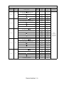
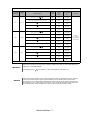
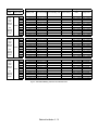
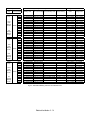
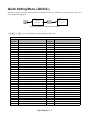
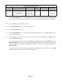
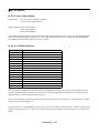
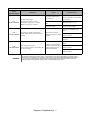
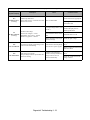
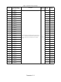
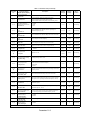
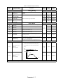
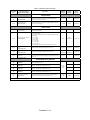
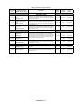
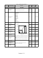
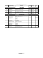
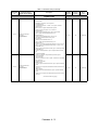
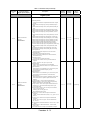
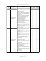
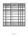
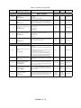
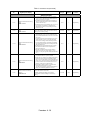
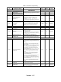
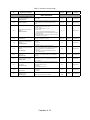
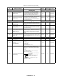
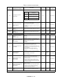
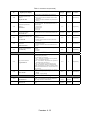
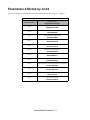
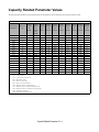
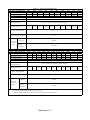
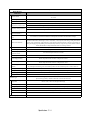
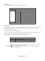
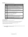
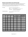
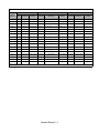
Quick Reference for P7 Parameters
Parameter
Number
Factory
Setting
A1-00
A1-01
User
Setting
Parameter
Number
Factory
Setting
User
Setting
Parameter
Number
Factory
Setting
User
Setting
Parameter
Number
Factory
Setting
0
b5-07
0
E1-07
3
L4-05
1
2
b5-08
0
E1-08
18
L4-06
80
A1-03
0
b5-09
0
E1-09
1.5
L5-01
0
A1-04
0
b5-10
1
E1-10
10.8
L5-02
0
A1-05
0
b5-11
0
E1-11
0
L5-03
180
A2-01
b5-12
0
E1-12
0
L6-01
6
A2-02
b5-13
0
E1-13
0
L6-02
15
A2-03
b5-14
1
E2-01
kVA Dep.
L6-03
10
A2-04
b5-15
0
E2-03
kVA Dep.
L8-01
0
A2-05
b5-16
0
E2-05
kVA Dep.
L8-02
kVA Dep.
A2-06
b5-17
0
F6-01
1
L8-03
4
A2-07
b5-18
0
F6-02
0
L8-06
kVA Dep.
A2-08
b5-19
0
F6-03
1
L8-09
1
A2-09
b5-20
1
F6-05
0
L8-10
0
A2-10
b5-21
1
H1-01
24
L8-11
300
A2-11
b5-22
0
H1-02
14
L8-12
45
A2-12
b5-23
0
H1-03
3
L8-15
1
A2-13
b5-24
0
H1-04
4
L8-18
1
A2-14
b5-25
0
H1-05
6
L8-19
20
1
A2-15
b5-26
0
H2-01
0
n1-01
A2-16
b5-27
60
H2-02
A
n1-02
1
A2-17
b5-28
0
H3-02
100
n3-01
5
150
A2-18
b5-29
1
H3-03
0
n3-02
A2-19
b5-30
0
H3-08
2
n3-03
1
A2-20
b8-01
0
H3-09
2
n3-04
40
A2-21
b8-04
kVA Dep.
H3-10
100
o1-01
6
A2-22
b8-05
20
H3-11
0
o1-02
1
A2-23
b8-06
0
H3-12
0.3
o1-03
0
A2-24
C1-01
30
H3-13
0
o1-05
3
A2-25
C1-02
30
H4-01
2
o1-06
0
A2-26
C1-03
30
H4-02
100
o1-07
2
A2-27
C1-04
30
H4-03
0
o1-08
3
A2-28
C1-09
10
H4-04
8
o2-01
1
A2-29
C1-11
0
H4-05
50
o2-02
1
A2-30
C2-01
0.2
H4-06
0
o2-03
0
A2-31
C2-02
0.2
H4-07
0
o2-04
kVA Dep.
A2-32
C4-01
1
H4-08
0
o2-05
1
1
b1-01
1
C4-02
200
H5-01
1F
o2-06
b1-02
1
C6-01
2
H5-02
3
o2-07
0
b1-03
0
C6-02
kVA Dep.
H5-03
0
o2-08
1
b1-04
1
C6-03
kVA Dep.
H5-04
3
o2-09
1
b1-07
0
C6-04
kVA Dep.
H5-05
1
o2-10
0
b1-08
0
C6-05
0
H5-06
5
o2-12
0
b1-11
0
d1-01
0
H5-07
1
o2-14
0
b1-12
0
d1-02
0
H5-09
2
o2-15
1
b2-01
0.5
d1-03
0
L1-01
1
o3-01
0
b2-02
50
d1-04
0
L1-02
8
o3-02
0
b2-03
0
d1-17
6
L1-03
3
T1-02
kVA Dep.
b2-04
0
d2-01
100
L1-04
1
T1-04
kVA Dep.
b2-09
0
d2-02
0
L1-05
0.2
b3-01
2
d2-03
0
L2-01
b3-02
120
d3-01
0
L2-02
kVA Dep.
b3-03
2
d3-02
0
L2-03
kVA Dep.
b3-05
0.2
d3-03
0
L2-04
kVA Dep.
b3-14
1
d3-04
1
L2-05
Voltage Dep.
b4-01
0
d4-01
0
L3-01
1
b4-02
0
d4-02
10
L3-02
120
b5-01
0
E1-01
240V or 480V
L3-04
1
b5-02
2
E1-03
F
L3-05
1
120
2
b5-03
5
E1-04
60
L3-06
b5-04
100
E1-05
240V or 480V
L4-01
0
b5-06
100
E1-06
60
L4-02
2
User
Setting
Warnings and Cautions
This Section provides warnings and cautions pertinent to this product, that if not
heeded, may result in personal injury, fatality, or equipment damage. Yaskawa is
not responsible for consequences of ignoring these instructions.
WARNING
YASKAWA manufactures component parts that can be used in a wide variety of industrial applications. The selection and
application of YASKAWA products remain the responsibility of the equipment designer or end user. YASKAWA accepts no
responsibility for the way its products are incorporated into the final system design. Under no circumstances should any
YASKAWA product be incorporated into any product or design as the exclusive or sole safety control. Without exception, all
controls should be designed to detect faults dynamically and fail safely under all circumstances. All products designed to
incorporate a component part manufactured by YASKAWA must be supplied to the end user with appropriate warnings and
instructions as to that part’s safe use and operation. Any warnings provided by YASKAWA must be promptly provided to the
end user. YASKAWA offers an express warranty only as to the quality of its products in conforming to standards and
specifications published in the YASKAWA manual. NO OTHER WARRANTY, EXPRESS OR IMPLIED, IS OFFERED.
YASKAWA assumes no liability for any personal injury, property damage, losses, or claims arising from misapplication of its
products.
WARNING
• Read and understand this manual before installing, operating, or servicing this Drive. All warnings, cautions, and
instructions must be followed. All activity must be performed by qualified personnel. The Drive must be installed according
to this manual and local codes.
• Do not connect or disconnect wiring while the power is on. Do not remove covers or touch circuit boards while the power is
on. Do not remove or insert the digital operator while power is on.
• Before servicing, disconnect all power to the equipment. The internal capacitor remains charged even after the power supply
is turned off. Status indicator LEDs and Digital Operator display will be extinguished when the DC bus voltage is below
50 VDC. To prevent electric shock, wait at least five minutes after all indicators are OFF and measure DC bus voltage level
to confirm safe level.
• Do not perform a withstand voltage test on any part of the unit. This equipment uses sensitive devices and may be damaged
by high voltage.
• The Drive is not suitable for circuits capable of delivering more than the specified RMS symmetrical amperes. Install
adequate branch short circuit protection per applicable codes. Refer to the specification. Failure to do so may result in
equipment damage and/or personal injury.
• Do not connect unapproved LC or RC interference suppression filters, capacitors, or overvoltage protection devices to the
output of the Drive. These devices may generate peak currents that exceed Drive specifications.
• To avoid unnecessary fault displays caused by contactors or output switches placed between Drive and motor, auxiliary
contacts must be properly integrated into the control logic circuit.
• YASKAWA is not responsible for any modification of the product made by the user; doing so will void the warranty. This
product must not be modified.
• Verify that the rated voltage of the Drive matches the voltage of the incoming power supply before applying power.
• To meet CE directives, proper line filters and proper installation are required.
Warnings i
WARNING
• Some drawings in this manual may be shown with protective covers or shields removed, to describe details. These must be
replaced before operation.
• Observe electrostatic discharge procedures when handling circuit cards to prevent ESD damage.
• The equipment may start unexpectedly upon application of power. Clear all personnel from the drive, motor, and machine
area before applying power. Secure covers, couplings, shaft keys, and machine loads before energizing the Drive.
• Please do not connect or operate any equipment with visible damage or missing parts. The operating company is responsible
for any injuries or equipment damage resulting from failure to heed the warnings in this manual.
! Intended Use
Drives are intended for installation in electrical systems or machinery.
For use in the European Union, the installation in machinery and systems must conform to the following product standards of
the Low Voltage Directive:
EN 50178, 1997-10, Equipping of Power Systems with Electronic Devices
EN 60201-1, 1997-12 Machine Safety and Equipping with Electrical Devices
Part 1: General Requirements (IEC 60204-1:1997)/
EN 61010, 1997-11Safety Requirements for Information Technology Equipment
(IEC 950:1991 + A1:1992 + A2:1993 + A3:1995 + A4:1996, modified)
CE certification per EN 50178 can be achieved using the line filters specified in this manual and following the appropriate
installation instructions.
!Other
The Drive is suitable for use on a circuit capable of delivering not more than 100,000 RMS symmetrical amperes, 240Vac maximum (240V Class) and 480Vac maximum (480V Class).
Warnings ii
Introduction
This Section describes the applicability of the Manual
The P7 Drive is a Pulse Width Modulated Drive for 3-Phase AC induction motors. This type of Drive is also known as an
Adjustable Frequency Drive, Variable Frequency Drive, AC Drive, AFD, ASD, VFD, and Inverter. In this manual, the P7
Drive will be referred to as the “Drive”.
The Drive is a variable torque AC drive, designed specifically for HVAC applications in building automation, including fans,
blowers and pumps. A new benchmark for size, cost, performance, benefits, and quality, the Drive includes numerous
built-in features such as network communications, H/O/A, PI, parameter storage and copy functions.
The Drive has embedded communications for Modbus®protocol. An optional LONWORKS® interface card is also available.
The LCD keypad/operator is equipped with local/remote functions, copy feature, 7 language choices, and 5 lines of display
with 16 characters per line. User parameter settings can be recovered at any time via “user initialization”. Optional software
allows upload/download, as well as graphing and monitoring of drive parameters from a PC for ease of drive management.
Built-in PI control eliminates the need for closed loop output signals from a building automation system. It includes feedback
display, inverse, square root and differential control functions, and maintains setpoint for closed loop control of fans and
pumps for pressure, flow, or temperature regulation.
This manual is applicable to Drives defined by model numbers CIMR-P7U_ _ _ _ . This manual reflects the Software
Version 1010.
This manual is subject to change as product improvements occur. The latest version of the manual can be obtained from the
Yaskawa website www.drives.com . The date shown on the rear cover is changed when revisions are made. The latest version
of Drive software is also shown.
Introduction iii
This manual may describe trademarked equipment, which is the property of other companies. These trademarks are the
property of the registered owner companies and may include the following:
Modbus®, trademark of Schneider Automation, Inc.
LONWORKS®, trademark of Echelon Corporation
Other Documents and Manuals are available to support special use or installation of this product. These documents may be
provided with the product or upon request. Contact Yaskawa Electric America, Inc. as required. Documents may include the
following:
TM.P7.02.Programming… Manual included on CD ROM with product
TM.AFD.11.Modbus… Manual included on CD ROM with product
TM.AFD.20.LONWORKS… Manual included on CD ROM with product
TM.P7B.01. Bypass… This manual should be used when the Drive is packaged with Bypass Control
DriveWizard ... Software and Manual…Included on CD ROM with product
Option Instructions… Included on CD ROM with product
Introduction iv
Table of Contents
Quick Reference Parameter List ....................................................... Inside front cover
Warnings and Cautions ................................................................................................ i
Introduction .................................................................................................................iii
Chapter 1- Physical Installation ................................................................................1-1
Model Number and Enclosure Style.........................................................................1-2
Confirmations Upon Delivery ...................................................................................1-3
Component Names ..................................................................................................1-5
Exterior and Mounting Dimensions ..........................................................................1-7
Heat Loss Data ...................................................................................................... 1-11
Checking and Controlling the Installation Site........................................................1-13
Installation Orientation and Clearances .................................................................1-14
Removing and Attaching the Terminal Cover.........................................................1-15
Removing/Attaching the Digital Operator and Front Cover ....................................1-16
Chapter 2- Electrical Installation...............................................................................2-1
Terminal Block Configuration ...................................................................................2-2
Wiring Main Circuit Terminals...................................................................................2-3
Control Wiring ........................................................................................................2-21
Chapter 3- Digital Operator........................................................................................3-1
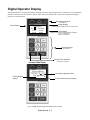
Digital Operator Display ...........................................................................................3-2
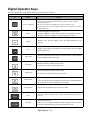
Digital Operator Keys ...............................................................................................3-3
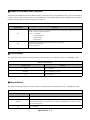
Drive Mode Indicators ..............................................................................................3-4
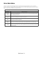
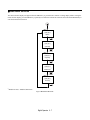
Drive Main Menu ......................................................................................................3-6
Quick Setting Menu (-QUICK-)............................................................................... 3-11
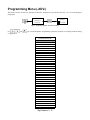
Programming Menu (-ADV-)...................................................................................3-12
Example of Changing a Parameter ........................................................................3-14
Table of Contents v
Chapter 4- Start Up.....................................................................................................4-1
Drive Start Up Preparation ....................................................................................... 4-2
Drive Start Up Procedures ....................................................................................... 4-5
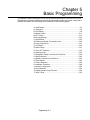
Chapter 5- Basic Programming................................................................................. 5-1
A1 Initialization ......................................................................................................... 5-2
b1 Sequence ............................................................................................................ 5-4
b2 DC Braking.......................................................................................................... 5-9
b3 Speed Search ................................................................................................... 5-11
b5 PI Function ........................................................................................................ 5-15
b8 Energy Savings ................................................................................................. 5-24
C1 Accel/Decel....................................................................................................... 5-25
d2 Reference (Speed Command) Limits ................................................................ 5-26
d3 Jump Frequencies............................................................................................. 5-27
E1 V/f pattern ......................................................................................................... 5-28
E2 Motor Setup ...................................................................................................... 5-31
F6 Com OPT Selection .......................................................................................... 5-32
H3 Analog Inputs.................................................................................................... 5-33
L2 Momentary Power Loss Ride-thru Function...................................................... 5-39
L3 Stall Prevention ................................................................................................. 5-40
L4 Speed Command Loss Detection...................................................................... 5-43
L5 Fault Restart...................................................................................................... 5-44
L6 Torque Detection ............................................................................................... 5-46
L8 Hardware Protection ......................................................................................... 5-48
o1 Monitor Configuration........................................................................................ 5-50
o2 Key Selections .................................................................................................. 5-54
o3 Digital Operator Copy Function......................................................................... 5-56
T1 Auto-Tuning ...................................................................................................... 5-59
Table of Contents vi
Chapter 6- Diagnostic & Troubleshooting .............................................................. 6-1
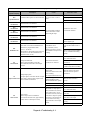
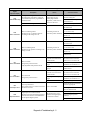
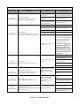
Fault Detection ......................................................................................................... 6-2
Alarm Detection........................................................................................................ 6-8
Operator Programming Errors (OPE)..................................................................... 6-11
Auto-Tuning Faults ................................................................................................. 6-12
Digital Operator COPY Function Faults ................................................................. 6-13
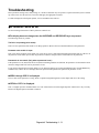
Troubleshooting ..................................................................................................... 6-14
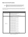
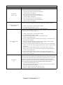
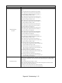
Main Circuit Test Procedure ................................................................................... 6-20
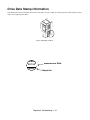
Drive Date Stamp Information ................................................................................ 6-24
Chapter 7- Maintenance ............................................................................................. 7-1
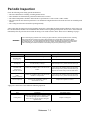
Periodic Inspection................................................................................................... 7-2
Preventative Maintenance........................................................................................ 7-3
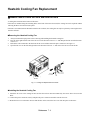
Heatsink Cooling Fan Replacement......................................................................... 7-4
Removing and Mounting the Terminal Card............................................................. 7-6
Appendix A - Parameters.......................................................................................... A-1
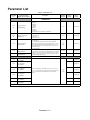
Parameter List..........................................................................................................A-2
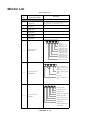
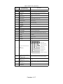
Monitor List.............................................................................................................A-26
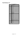
Fault Trace List ......................................................................................................A-28
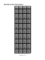
Fault Trace History .................................................................................................A-29
Appendix B - Capacity Related Parameters ............................................................ B-1
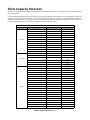
Drive Capacity Selection ..........................................................................................B-2
Parameters Affected by o-04 ...................................................................................B-3
Appendix C - Specifications ..................................................................................... C-1
Standard Drive Specification ................................................................................... C-2
Table of Contents vii
Appendix D - Communications ................................................................................ D-1
Using Modbus Communication ............................................................................... D-2
Modbus Function Code Details ............................................................................... D-7
Modbus Data Tables ............................................................................................... D-9
Modbus Self- Diagnosis ........................................................................................ D-14
Appendix E - Peripheral Devices ............................................................................. E-1
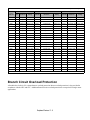
Branch Circuit Short Circuit Protection.....................................................................E-2
Branch Circuit Overload Protection..........................................................................E-5
Peripheral Devices ...................................................................................................E-6
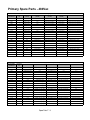
Appendix F - Spare Parts ...........................................................................................F-1
Primary Spare Parts - 208/230/240Vac ....................................................................F-2
Primary Spare Parts - 480Vac ..................................................................................F-3
Appendix G - EMC Compatibility ............................................................................. G-1
EMC Compatibility................................................................................................... G-2
Electromagnetic Compatibility (EMC) ..................................................................... G-3
Index .................................................................................................................... Index-1
Support Services ................................................................................ Inside rear cover
Table of Contents viii
Chapter 1
Physical Installation
This chapter describes the requirements for receiving and installing the Drive.
Model Number and Enclosure Style ....................................1-2
Confirmations upon Delivery ...............................................1-3
Component Names..............................................................1-5
Exterior and Mounting Dimensions......................................1-7
Heat Loss Data .................................................................. 1-11
Checking and Controlling the Installation Site ...................1-13
Installation Orientation and Clearances.............................1-14
Removing and Attaching the Terminal Cover ....................1-15
Removing/Attaching the Digital Operator
and Front Cover.................................................................1-16
Physical Installation 1 - 1
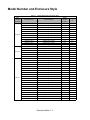
Model Number and Enclosure Style
Table 1.1 Model Numbers and Enclosure Style
Input
Voltage
3-Phase
208-240Vac
208-230Vac
480 Vac
Model-Number
Enclosure Style
CIMR-P7U20P4
CIMR-P7U20P7
CIMR-P7U21P5
CIMR-P7U22P2
CIMR-P7U23P7
CIMR-P7U25P5
CIMR-P7U27P5
CIMR-P7U2011
CIMR-P7U2015
CIMR-P7U2018
CIMR-P7U2022
CIMR-P7U2030
CIMR-P7U2037
CIMR-P7U2045
CIMR-P7U2055
CIMR-P7U2075
CIMR-P7U2090
CIMR-P7U2110
CIMR-P7U40P4
CIMR-P7U40P7
CIMR-P7U41P5
CIMR-P7U42P2
CIMR-P7U43P7
CIMR-P7U45P5
CIMR-P7U47P5
CIMR-P7U4011
CIMR-P7U4015
CIMR-P7U4018
CIMR-P7U4030
CIMR-P7U4037
CIMR-P7U4045
CIMR-P7U4055
CIMR-P7U4075
CIMR-P7U4090
CIMR-P7U4110
CIMR-P7U4160
CIMR-P7U4185
CIMR-P7U4220
CIMR-P7U4300
NEMA Type 1 (IP20)
NEMA Type 1 (IP20)
NEMA Type 1 (IP20)
NEMA Type 1 (IP20)
NEMA Type 1 (IP20)
NEMA Type 1 (IP20)
NEMA Type 1 (IP20)
NEMA Type 1 (IP20)
NEMA Type 1 (IP20)
NEMA Type 1 (IP20)
NEMA Type 1 (IP20)
NEMA Type 1 (IP20)
Open Chassis (IP00)
Open Chassis (IP00)
Open Chassis (IP00)
Open Chassis (IP00)
Open Chassis (IP00)
Open Chassis (IP00)
NEMA Type 1 (IP20)
NEMA Type 1 (IP20)
NEMA Type 1 (IP20)
NEMA Type 1 (IP20)
NEMA Type 1 (IP20)
NEMA Type 1 (IP20)
NEMA Type 1 (IP20)
NEMA Type 1 (IP20)
NEMA Type 1 (IP20)
NEMA Type 1 (IP20)
NEMA Type 1 (IP20)
NEMA Type 1 (IP20)
NEMA Type 1 (IP20)
NEMA Type 1 (IP20)
Open Chassis (IP00)
Open Chassis (IP00)
Open Chassis (IP00)
Open Chassis (IP00)
Open Chassis (IP00)
Open Chassis (IP00)
Open Chassis (IP00)
Physical Installation 1 - 2
Rated
Output
Current
3.6
4.6
7.8
10.8
16.8
23.0
31.0
46.2
59.4
74.8
88.0
115.0
162.0
192.0
215.0
312.0
360.0
415.0
1.8
2.1
3.7
5.3
7.6
12.5
17.0
27.0
34.0
40.0
67.2
77.0
96.0
125.0
156.0
180.0
240.0
304.0
414.0
515.0
675.0
Nominal
Hp
0.5/0.75
1
1.5/2
3
5
7.5
7.5/10
15
20
25
30
40
50/60
60/75
75
100/125
125/150
150
0.5/0.75
1
1.5/2
3
5
7.5
10
15/20
25
30
40/50
60
75
100
125
150
200
250
300/350
400/450
500+
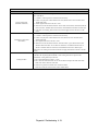
Confirmations upon Delivery
! Receiving Checks
Check the following items as soon as the Drive is received.
Table 1.2 Receiving Checks
Item
Method
Has the correct model of Drive been
delivered?
Check the model number on the nameplate on the right side of the Drive.
Reconcile with packing slip and/or order information.
Is the Drive damaged in any way?
Inspect the entire exterior of the Drive to see if there are any dents, scratches or
other damage resulting from shipping.
Are any screws or other components
loose?
Use a screwdriver or other tool to check for tightness.
If there are any irregularities in the above items, contact the shipping company, the distributor or representative who sold the
Drive, or a Yaskawa office immediately.
The P7 is thoroughly tested at the factory. Any damages or shortages evident when the equipment is received must be reported
immediately to the commercial carrier that transported the material. Shipping damage is not covered by the Yaskawa warranty.
After unpacking and inspecting for damage, verify that internal wire connections have not come loose during shipment by spot
checking wire terminations with a screwdriver or the appropriate tool.
P7 Drive storage must be in a clean and dry location. Maintain the factory packaging and provide covering as needed to
protect the P7 from construction site dirt, water, debris and traffic prior to and during construction.
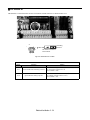
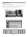
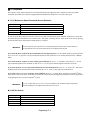
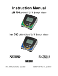
! Nameplate Information
A nameplate is attached to the right side of each Drive. The following nameplate is an example for a standard Drive.
Note: The Drive Model Number and Drive Spec Number are required to completely identify a Drive.
Fig 1.1 Drive Nameplate
Physical Installation 1 - 3
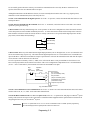
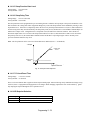
! Drive Model Numbers
The model number on the nameplate indicates the design specification, voltage, and rating of the Drive in alphanumeric codes.
CIMR – P7 U 2 0 11
AC Drive
P7 Family
No.
2
4
Rating
Spec
UL Specification
No.
U
Voltage
3-phase, 208-240Vac
3-phase, 480Vac
Fig 1.2 Drive Model Number Structure
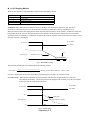
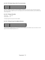
! Drive Enclosure and Revision Code
The Drive SPEC number on the nameplate indicates the voltage, Drive rating, enclosure type, and the revision code of the
Drive in alphanumeric codes.
2 011 1 A
No.
Voltage
2
4
3-phase, 208 - 240Vac
Hardware Revision
3-phase, 480Vac
Rating
No.
0
1
Enclosure Type
Open chassis (IEC IP00)
NEMA Type 1 (IEC IP20)
Fig 1.3 SPEC Number Structure
Open Chassis Type (IEC IP00)
Protected so that parts of the human body cannot reach electrically charged parts from the front when the
Drive is mounted in a control panel, also called (protected chassis).
TERMS
NEMA Type 1 (IEC IP20)
The Drive is shielded from the exterior, and can thus be mounted to the interior wall of a building
(not necessarily enclosed in a control panel). The protective structure conforms to the standards of NEMA
Type 1 in the USA. All protective covers (Fig 1.4) must be installed to conform with IEC IP20 and NEMA Type
1 requirements.
Physical Installation 1 - 4
Component Names
! Models CIMR-P7U20P4 thru 2018 (25HP @ 208V/240V) and 40P4 thru 4018
(30HP @ 480V)
The external appearance, component names, and terminal arrangement of the Drive are shown in Fig 1.4. and 1.5.
Top protective cover
Mounting hole
Front cover
Digital Operator
Diecast Heat Sink
Nameplate
Terminal cover
Bottom protective cover
Fig 1.4 Drive Appearance
Fig 1.5 Terminal Arrangement (Terminal Cover Removed)
Physical Installation 1 - 5
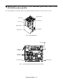
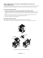
! Models CIMR-P7U2022 thru 2110 (30HP and above @ 208V/240V) and 4030 thru
4300 (40HP and above @ 480V)
The external appearance, component names, and terminal arrangement of the Drive are shown in Fig 1.6 and 1.7.
Mounting
holes
Mounting
holes
Drive cover
Drive cover
Cooling
fan
Cooling
fan
Front
Frontcover
cover
Digital Operator
Operator
Digital
Nameplate
Nameplate
Terminal
cover
Terminal
cover
Fig 1.6 Drive Appearance
Charge indicator
Control circuit
terminals
Main circuit
terminals
Ground terminal
Ground terminal
Fig 1.7 Terminal Arrangement (Terminal Cover Removed)
Physical Installation 1 - 6
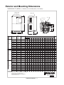
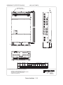
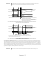
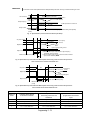
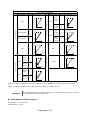
Exterior and Mounting Dimensions
DIMENSIONS: P7 (NEMA 1) 208/240V (3.6-74.8 AMPS) 480V (1.8-40 AMPS)
FRONT VIEW
SIDE VIEW
MOUNTING HOLES
FOR "A" SIZE SCREW
AIR
H2
1.38 DIA.
(2) HOLES SIZE "J"
.87 DIA.
C
L
H
H
B
E
C
AIR
W2
W
D
W
RATED
INPUT
208V
240V
480V
BOTTOM VIEW
D
MODEL
CIMR-P7U
RATED
OUTPUT
CURRENT
(AMPS)
H
W
H2
W2
D
D1
A
C
E
F
J
APPROX.
WEIGHT
(LBS.)
20P41
3.6
1/2 3/4
10.47
4.96
11.02
5.51
.28
.28
6.30
1.54
#10
---
3.35
4.73
1.97
1.10
6.6
20P71
4.6
1
10.47
4.96
11.02
5.51
.28
.28
6.30
1.54
#10
---
3.35
4.73
1.97
1.10
6.6
21P51
7.8
2
10.47
4.96
11.02
5.51
.28
.28
6.30
1.54
#10
---
3.35
4.73
1.97
1.10
6.6
22P21
10.8
3
10.47
4.96
11.02
5.51
.28
.28
6.30
1.54
#10
---
3.35
4.73
1.97
1.10
6.6
23P71
16.8
5
10.47
4.96
11.02
5.51
.28
.28
7.09
2.32
#10
---
4.14
5.52
1.97
1.10
8.8
27P51
31.0
7.5-10
11.22
7.32
11.81 7.87
.28
.28
7.87
2.58
4.63
5.11
6.21
3.07
1.38
13.2
20111
46.2
15
11.22
7.32
12.20
7.87
.28
.28
7.87
2.58
1/4
4.63
5.11
6.21
3.07
1.38
15.4
20151
59.4
20
13.19
8.50
13.78
9.45
.30
.47
8.27
3.07
1/4
5.12
5.79
6.65
3.94
1.73
24.2
14.96
DIMENSIONS IN INCHES
NOMINAL
HP
MOUNTING
H1
W1
1/4
B
20181
74.8
25
13.19
8.50
9.45
.30
.47
8.27
3.07
1/4
5.12
5.79
6.65
3.94
1.73
24.2
20P41
3.6
1/2 3/4
-
10.47
4.96
11.02
5.51
.28
.28
6.30
1.54
#10
---
3.35
4.73
1.97
1.10
6.6
20P71
4.6
1
10.47
4.96
11.02
5.51
.28
.28
6.30
1.54
#10
---
3.35
4.73
1.97
1.10
6.6
21P51
7.8
2
10.47
4.96
11.02
5.51
.28
.28
6.30
1.54
#10
---
3.35
4.73
1.97
1.10
6.6
22P21
10.8
3
10.47
4.96
11.02
5.51
.28
.28
6.30
1.54
#10
---
3.35
4.73
1.97
1.10
6.6
23P71
16.8
5
10.47
4.96
11.02
5.51
.28
.28
7.09
2.32
#10
---
4.14
5.52
1.97
1.10
8.8
25P51
23.0
7.5
10.47
4.96
11.02
5.51
.28
.28
7.09
2.32
#10
---
4.14
5.52
1.97
1.10
8.8
13.2
27P51
31.0
10
11.22
7.32
.28
.28
7.87
2.58
4.63
5.11
6.21
3.07
1.38
20111
46.2
15
11.22
7.32
12.20
7.87
.28
.28
7.87
2.58
1/4
4.63
5.11
6.21
3.07
1.38
15.4
20151
59.4
20
13.19
8.50
13.78
9.45
.30
.47
8.27
3.07
1/4
5.12
5.79
6.65
3.94
1.73
24.2
20181
74.8
25
13.19
8.50
14.96
9.45
.30
.47
8.27
3.07
1/4
5.12
5.79
6.65
3.94
1.73
24.2
40P41
1.8
1/2 3/4
-
10.47
4.96
11.02
5.51
.28
.28
6.30
1.54
#10
---
3.35
4.73
1.97
1.10
6.6
40P71
2.1
1
10.47
4.96
11.02
5.51
.28
.28
6.30
1.54
#10
---
3.35
4.73
1.97
1.10
6.6
41P51
3.7
2
10.47
4.96
11.02
5.51
.28
.28
6.30
1.54
#10
---
3.35
4.73
1.97
1.10
6.6
11.81 7.87
1/4
42P21
5.3
3
10.47
4.96
11.02
5.51
.28
.28
7.09
2.32
#10
---
4.14
5.52
1.97
1.10
8.8
43P71
7.6
5
10.47
4.96
11.02
5.51
.28
.28
7.09
2.32
#10
---
4.14
5.52
1.97
1.10
8.8
45P51
12.5
7.5
10.47
4.96
11.02
5.51
.28
.28
7.09
2.32
#10
---
4.14
5.52
1.97
1.10
8.8
47P51
17.0
10
11.22
7.32
11.81 7.87
.28
.28
7.87
2.58
4.63
5.11
6.21
3.07
1.38
13.2
4.63
5.11
6.21
3.07
1.38
13.2
5.12
5.79
6.65
3.94
1.73
22
5.12
5.79
6.65
3.94
1.73
22
40111
27.0
15-20
11.22
7.32
11.81
7.87
.28
.28
7.87
2.58
40151
34.0
25
13.19
8.50
13.78
9.45
.30
.47
8.27
3.07
40181
40.0
30
13.19
8.50
13.78
9.45
.30
.47
8.27
3.07
1/4
1/4
1/4
1/4
FOR REFERENCE ONLY UNLESS PROPERLY ENDORSED.
IN ORDER TO ACHIEVE ADEQUATE COOLING
THE DRIVE MUST BE POSITIONED TO ALLOW A MINIMUM
OF FREE AIR SPACE OF 1.2 INCHES ON SIDES AND
5 INCHES TOP AND BOTTOM
DR BY
APPVL.
Physical Installation 1 - 7
RIP 8.29.02
TBS 9.5.02
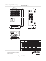
DIMENSIONS: P7 (NEMA 1)
208/240V (88-115 AMPS) 480V (67.2-125 AMPS)
W
W
W2
H2
H
H
MOUNTING HOLES
FOR "A" SIZE SCREWS
SIZE "K" HOLE
(2) HOLES SIZE "L"
CL
(2) HOLES SIZE "J"
D
E
C
B
D
F
G
RATED
OUTPUT
CURRENT
(AMPS)
NOM.
HP
H1
W1
20221
88
30
15.16
7.68
21.06
10.00
.30
20301
115
40
17.13
8.66
24.21
10.98
.30
20221
88
30
15.16
7.68
21.06
10.00
20301
115
40
17.13
8.66
24.21
40221
50.4
30
17.13
8.66
40301
67.2
40-50
17.13
40371
77
75
MODEL
RATED
INPUT CIMR-P7U
208V
240V
480V
DIMENSIONS IN INCHES
F
G
J
K
L
APPROX.
WEIGHT
(LBS.)
7.87
1.73
5.91
2.44
1.97
1.10
53
7.87
1.73
5.91
2.44
1.97
1.10
59
6.50
7.87
1.73
5.91
2.44
1.97
1.10
53
4.98
6.50
7.87
1.73
5.91
2.44
1.97
1.10
59
1/4
4.98
6.50
7.87
1.73
5.91
1.97
1.97
1.10
53
3.94
1/4
4.98
6.50
7.87
1.73
5.91
1.97
1.97
1.10
53
11.22
4.13
1/4
5.18
6.69
8.07
1.73
6.69
1.97
1.97
1.10
88
MOUNTING
H
H2
W
W2
D
D1
A
B
C
E
1.16
10.24
3.94
1/4
1.16
10.24
3.94
1/4
4.98
6.50
4.98
6.50
.30
1.16
10.24
3.94
1/4
4.98
10.98
.30
1.16
10.24
3.94
1/4
21.06
10.98
.30
1.16
10.24
3.94
8.66
21.06
10.98
.30
1.16
10.24
21.06
10.24
25.00
12.95
.30
1.36
40451
96
60
21.06
10.24
28.15
12.95
.30
1.36
11.22
4.13
1/4
5.18
6.69
8.07
1.73
6.69
2.44
1.97
1.10
88
40551
125
100
21.06
10.24
28.15
12.95
.30
1.36
11.22
4.13
1/4
5.18
6.69
8.07
1.73
6.69
2.44
1.97
1.10
88
FOR REFERENCE ONLY UNLESS PROPERLY ENDORSED.
IN ORDER TO ACHIEVE ADEQUATE COOLING
THE DRIVE MUST BE POSITIONED TO ALLOW A MINIMUM
OF FREE AIR SPACE OF 1.2 INCHES ON SIDES AND
5 INCHES TOP AND BOTTOM
Physical Installation 1 - 8
DR BY
APPVL.
RIP 8-02
TBS 9.5.02
208-230V (162-396 AMPS)
480V (156-304 AMPS)
DIMENSIONS: P7 (PROTECTED CHASSIS)
FRONT VIEW
MOUNTING HOLES
FOR "A" SIZE SCREW
AIR
H2
H
H
AIR
W2
W
D
D
W
RATED
OUTPUT
CURRENT
(AMPS)
NOM.
HP
20370
162
20450
192
20550
MODEL
RATED
INPUT CIMR-P7U
208V
230V
480V
DIMENSIONS IN INCHES
MOUNTING
H
W
D1
A
9.84
23.62
14.76
.49
9.84
23.62
14.76
.49
2.46
11.81
3.94
3/8
125
2.46
12.99
5.12
3/8
27.56
12.80
28.54
17.72
139
.49
2.46
13.78
5.12
3/8
100
27.56
12.80
28.54
189
17.72
.49
2.46
13.78
5.12
3/8
125
32.28
14.57
191
33.46
19.69
.59
2.56
14.17
5.12
3/8
238
150
33.66
50-60
22.64
17.52
34.84
22.64
.59
2.56
14.96
5.51
3/8
330
9.84
23.62
14.76
.49
2.46
11.81
3.94
3/8
75
125
22.64
9.84
23.62
14.76
.49
2.46
12.99
5.12
3/8
312
139
100-125
27.56
12.80
28.54
17.72
.49
2.46
13.78
5.12
3/8
20900
191
360
150
32.28
14.57
33.46
19.69
.59
2.56
14.17
5.12
3/8
238
40750
156
125
27.56
12.80
28.54
17.72
.49
2.46
13.78
5.12
3/8
194
40900
180
150
27.56
12.80
28.54
17.72
.49
2.46
13.78
5.12
3/8
196
41100
240
200
32.28
14.57
33.46
19.69
.59
2.56
14.17
5.12
3/8
224
41600
304
250
33.66
17.52
36.06
22.64
.59
2.56
14.96
5.51
3/8
352
W1
50
22.64
60
22.64
215
75
20750
312
20900
360
21100
415
20370
162
20450
192
20750
H2
W2
APPROX.
WEIGHT
(LBS.)
D
H1
FOR REFERENCE ONLY UNLESS PROPERLY ENDORSED.
IN ORDER TO ACHIEVE ADEQUATE COOLING
THE DRIVE MUST BE POSITIONED TO ALLOW A MINIMUM
OF FREE AIR SPACE OF 1.2 INCHES ON SIDES AND
5 INCHES TOP AND BOTTOM
Physical Installation 1 - 9
DR BY
APPVL.
RIP 8.29.02
TBS 9.5.02
DIMENSIONS: P7 (PROTECTED CHASSIS)
480V (414-675 AMPS)
MOUNTING HOLES
FOR "A" SIZE SCREWS
AIR
H2
H H
W2
W
W
AIR
W
D
D
MODEL
RATED
INPUT CIMR-P7U
480V
RATED
OUTPUT
CURRENT
(AMPS)
DIMENSIONS IN INCHES
NOM.
HP
MOUNTING
H
W
H2
W2
D
D1
A
APPROX.
WEIGHT
(LBS.)
H1
W1
41850
414
300-350
50.00
10.63
51.38
27.95
.79
3.35
16.34
4.94
3/8
572
42200
515
400-450
50.00
10.63
51.38
27.95
.79
3.35
16.34
4.94
3/8
616
43000
675
56.70
14.37
58.07
36.06
.79
3.66
16.34
4.94
3/8
891
500
FOR REFERENCE ONLY UNLESS PROPERLY ENDORSED.
IN ORDER TO ACHIEVE ADEQUATE COOLING
THE DRIVE MUST BE POSITIONED TO ALLOW A MINIMUM
OF FREE AIR OF 1.2 INCHES ON SIDES AND
5 INCHES TOP AND BOTTOM
Physical Installation 1 - 10
DR BY
APPVL.
RIP 8-02
TBS 9.5.02
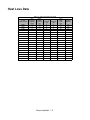
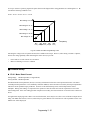
Heat Loss Data
TYPE
CIMR-P7U"
20P4
20P7
21P5
22P2
23P7
25P5
27P5
2011
2015
2018
2022
2030
2037
2045
2055
2075
2090
2110
Table 1.3 200V Class Heat Loss Data
Drive
Rated
Cooling
Internal
(Inverter)
Output
Fin Side Unit Side
Capacity
Current
(W)
(W)
(kVA)
(A)
1.4
3.6
19
39
1.8
4.6
26
42
3.0
7.8
48
50
4.1
10.8
68
59
6.4
16.8
110
74
8.8
23
164
84
12
31
219
113
18
46.2
357
168
23
59.4
416
182
29
74.8
472
208
34
88
583
252
44
115
883
333
62
162
1010
421
73
192
1228
499
82
215
1588
619
120
312
1956
844
140
360
2194
964
160
415
2733
1234
Physical Installation 1 - 11
Total
Watt
Loss
(W)
58
68
98
127
184
248
332
524
597
680
835
1217
1430
1727
2206
2800
3157
3967
Cooling
Method
Self
Self
Self
Self
Fan
Fan
Fan
Fan
Fan
Fan
Fan
Fan
Fan
Fan
Fan
Fan
Fan
Fan
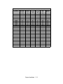
TYPE
CIMR-P7U"
40P4
40P7
41P5
42P2
43P7
44P0
45P5
47P5
4011
4015
4018
4022
4030
4037
4045
4055
4075
4090
4110
4132
4160
4185
4220
4300
Table 1.4 400V Class Heat Loss Data
Drive
Rated
Cooling
Internal
(Inverter)
Output
Fin Side Unit Side
Capacity
Current
(W)
(W)
(kVA)
(A)
1.4
1.8
14
39
1.6
2.1
17
41
2.8
3.7
36
48
4.0
5.3
59
56
5.8
7.6
80
68
6.6
8.7
90
70
9.5
12.5
127
81
13
17
193
114
21
27
232
158
26
34
296
169
30
40
389
201
38
50.4
420
233
51
67.2
691
297
59
77
801
332
73
96
901
386
95
125
1204
478
120
156
1285
562
140
180
1614
673
180
240
1889
847
200
260
2388
1005
230
304
2636
1144
315
414
2791
1328
390
515
3797
1712
510
675
5838
2482
Physical Installation 1 - 12
Total
Watt
Loss
(W)
53
58
84
115
140
160
209
307
390
465
590
653
989
1133
1287
1682
1847
2287
2736
3393
3936
3964
5509
8319
Cooling
Method
Self
Self
Self
Fan
Fan
Fan
Fan
Fan
Fan
Fan
Fan
Fan
Fan
Fan
Fan
Fan
Fan
Fan
Fan
Fan
Fan
Fan
Fan
Fan
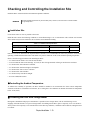
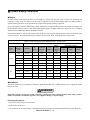
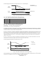
Checking and Controlling the Installation Site
Install the Drive as described below and maintain optimum conditions.
WARNING
The Drive heatsink temperature may exceed 158°F (70°C). Therefore, mount the Drive to a surface suitable
for high temperature.
! Installation Site
Locate the P7 Drive as close as possible to the motor.
Install the Drive under the following conditions in UL Pollution Degree 1 & 2 environments. This excludes wet locations
where surfaces may become conductive due to moisture and contaminant loading.
Table 1.5 Installation Site Specifications
Type
Ambient Operating Temperature
Humidity
Plenum Rated
NEMA Type 1
14°F-to-104°F (-10-to-+40°C)
95%-RH-or-less-(no-condensation)
Yes
Open Chassis
14°F-to-113°F (-10-to-+45 °C)
95%-RH-or-less-(no-condensation)
No
Protective covers are attached to the top and bottom of the Drive. It is recommended to remove the protective covers before
operating a CIMR-P7U2030/4055 Drive and smaller in a panel to obtain the 113°F (45°C) ambient operating temperature.
Observe the following precautions when installing the Drive:
• in a clean location which is free from oil mist and dust.
• in an environment where metal shavings, oil, water, or other foreign materials will not get into the Drive enclosure.
• in a location free from radioactive materials.
• in a location free from harmful gasses and liquids.
• in a location free from excessive vibration.
• in a location free from chlorides.
• in a location away from direct sunlight.
• on a non-combustible surface.
!Controlling the Ambient Temperature
To enhance the reliability of operation, the Drive should be installed in an environment free from extreme temperature
variations. If the Drive is installed in an enclosure, use a cooling fan or air conditioner to maintain the internal air temperature
below 113°F (45°C).
! Protecting the Drive from Foreign Matter
During Drive installation and project construction it is possible to have foreign matter, such as metal shavings or wire
clippings, fall inside the Drive. To prevent foreign matter from falling into the Drive, place a temporary cover over the Drive.
Always remove the temporary cover from the Drive before Start-Up. Otherwise, ventilation will be reduced, causing the Drive
to overheat.
Physical Installation 1 - 13
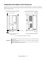
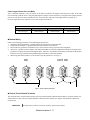
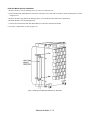
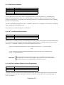
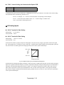
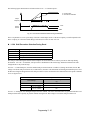
Installation Orientation and Clearances
Install the Drive vertically so as not to reduce the cooling efficiency. When installing the Drive, always provide the following
installation clearances to allow normal heat dissipation. Ensure that the heatsink is against a closed surface to avoid diverting
cooling air around the heatsink.
4.75 in (120 mm. minimum)
4.75 in (120 mm. minimum)
Air
1.2 in
(30.5 MM.) min.
1.2 in
(30.5 mm. minimum)
1.2 in
(30.5 mm. minimum)
4.75 in (50 mm. minimum)
4.75 in (120 mm. minimum)
Air
Horizontal Clearance
Vertical Clearance
Fig 1.8 Drive Installation Orientation and Clearance
IMPORTANT
1. The same clearance is required horizontally and vertically for both Open Chassis (IP00) and NEMA
Type 1 Drives.
2. Always remove the top and bottom protection covers before installing a CIMR-P7U2018/4018 and
smaller Drive in a panel.
Always provide enough clearance for lifting eye bolts and the main circuit wiring when installing a
CIMR-P7U2022/4030 and larger Drive in a panel.
Physical Installation 1 - 14
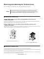
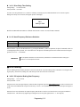
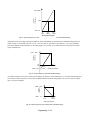
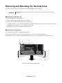
Removing and Attaching the Terminal Cover
Remove the terminal cover to connect cables to the control circuit and main circuit terminals.
WARNING
Prior to removing any protective cover or wiring any part of the Drive, remove all power sources, including
main input power and control circuit power. Wait a minimum of 5 minutes after power removal, before
removing any cover. The charge lamp located within the Drive should be off prior to working inside. Even if
the charge lamp is off, one must measure the AC input, output, and DC Bus potential to insure safe levels
prior to resuming work. Failure to adhere to this warning may result in personal injury or death.
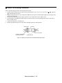
! Removing the Terminal Cover
# Models CIMR-P7U20P4 thru 2018 (0.5HP to 25HP @ 208V/240V) and 40P4 thru 4018
(0.5HP to 30HP @ 480V)
Loosen the screw at the bottom of the terminal cover, press in on the sides of the terminal cover in the directions of arrow 1,
and then lift up on the terminal in the direction of arrow 2. Refer to Figure 1.9
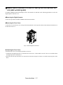
# Models CIMR-P7U2022 thru 2110 (30HP to 150HP @ 208V/240V) and 4030 thru 4300
(40HP to 500HP @ 480V)
Loosen the screws on the left and right at the top of the terminal cover, pull down the terminal cover in the direction of arrow
1 and then lift up on the terminal cover in the direction of arrow 2. Refer to Figure 1.10
1
2
Fig 1.9 Removing the Terminal Cover
Fig 1.10 Removing the Terminal Cover
! Attaching the Terminal Cover
After wiring the terminal block, attach the terminal cover by reversing the removal procedure.
For Models CIMR-P7U2018/4018 and smaller, insert the tab on the top of the terminal cover into the groove on the Drive and
press in on the bottom of the terminal cover until it snaps into place.
For Drives CIMR-P7U2022/4030 and larger, insert the tab on the top of the terminal cover into the groove on the Drive, and
secure the terminal cover by lifting it up toward the top of the Drive.
Physical Installation 1 - 15
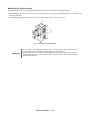
Removing/Attaching the Digital Operator and Front Cover
! Models CIMR-P7U20P4 thru 2018 (0.5HP to 25HP @ 208V/240V) and 40P4 thru
4018 (0.5HP to 30HP @ 480V)
For Models CIMR-P7U2018/4018 and smaller, remove the terminal cover and then use the following procedures to remove
the Digital Operator and front cover.
#Removing the Digital Operator
Press on the side of the Digital Operator in the direction of arrow 1 to unlock, then lift the Digital Operator in the direction of
arrow 2 to remove it as shown in Fig 1.11.
2
1
Fig 1.11 Removing the Digital Operator
#Removing the Front Cover
Press the left and right sides of the front cover in the direction of arrows 1 and lift the bottom of cover in the direction of arrow
2 to remove it as shown in Fig 1.12.
1
2
Fig 1.12 Removing the Front Cover
#Attaching the Front Cover
Mount the front cover to the Drive by performing the steps to remove the front cover in reverse order.
1. Do not mount the front cover with the Digital Operator attached to the front cover; this may cause the Digital Operator to
malfunction due to imperfect contact.
2. Insert the tab of the upper part of the front cover into the groove of the Drive and press the lower part of the front cover onto
the Drive until the front cover snaps into place.
Physical Installation 1 - 16
! Models CIMR-P7U2022 thru 2110 (30HP to 150HP @ 208V/240V) and 4030 thru
4300 (40HP to 500HP @ 480V)
For Models CIMR-P7U2022/4030 and larger, remove the terminal cover and then use the following procedures to remove the
Digital Operator and front cover.
#Removing the Digital Operator
Use the same procedure for Models CIMR-P7U2018/4018 and smaller.
#Removing the Front Cover
Loosen all screws on the front cover. Lift up at the location labeled 1 at the top of the control circuit terminal card and move in
the direction of arrow 2.
2
1
Fig 1.13 Removing the Front Cover
# Attaching the Front Cover
Attach the front cover by reversing the procedure to remove it.
1.Confirm that the Digital Operator is not mounted on the front cover. Contact faults can occur if the cover is attached while
the Digital Operator is mounted to it.
2.Insert the tab on the top of the front cover into the slot on the Drive and press in on the cover until it snaps into place on the
Drive.
Physical Installation 1 - 17
#Attaching the Digital Operator
After attaching the front cover, mount the Digital Operator onto the Drive using the following procedure.
1. Hook the Digital Operator at A (two locations) on the front cover by moving in the direction of arrow 1 as shown in the
following illustration.
2. Press the Digital Operator in the direction of arrow 2 until it snaps in place at B (two locations).
A
1
B
2
Fig 1.14 Mounting the Digital Operator
IMPORTANT
1. Do not remove or attach the Digital Operator or mount or remove the front cover using methods other
than those described above, damage to the Digital Operator or Drive may occur.
2. Never attach the front cover to the Drive with the Digital Operator attached to the front cover. Damage to
the Digital Operator may occur. Always attach the front cover to the Drive first, and then attach the Digital
Operator to the front cover.
Physical Installation 1 - 18
Chapter 2
Electrical Installation
This chapter describes wiring terminals, main circuit terminal connections, main
circuit terminal wiring specifications, control circuit terminals, and control circuit
wiring specifications.
Terminal Block Configuration .............................................2-2
Wiring Main Circuit Terminals............................................ 2-3
Control Wiring ................................................................. 2-21
Electrical Installation 2 - 1
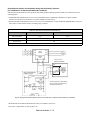
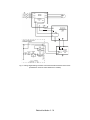
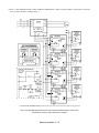
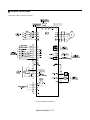
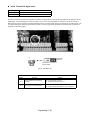
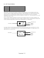
Terminal Block Configuration
The wiring terminals are shown in Fig 2.1.
SN SC SP A1 A2 +V AC -V
E(G)
MP AC RP R+ R-
S1 S2 S3 S4 S5 S6 S7 FM AC AM IG S+ S-
M5 M6 MA MB MC
M3 M4 M1
M2
E(G)
Control circuit terminals
Main circuit terminals
Charge indicator
Ground terminal
Ground terminal
Models CIMR-_ _ _2018 (25 HP, 208V)/
4018 (30 HP, 480V) and smaller
SN SC SP A1 A2 +V AC -V MP AC RP R+ RE(G)
S1 S2 S3 S4 S5 S6 S7 FM AC AM IG S+ S-
M5 M6 MA MB MC
M3 M4 M1
M2
E(G)
Control circuit terminals
Charge indicator
Main circuit terminals
Ground terminal
Ground terminal
Models CIMR-_ _ _2022 (30 HP, 208V)/
4030 (40 HP, 480V) and larger
Fig 2.1 Control Circuit Terminal Layout
Electrical Installation 2 - 2
Wiring Main Circuit Terminals
! Applicable Wire Sizes and Closed-loop Connectors
Select the appropriate wires and crimp terminals from Table 2.1 to Table 2.2.
Table 2.1 208-240Vac Wire Sizes and Connector Specifications
Drive Model
CIMR-P7U
Nominal
Hp
0.5/0.75
R/L1, S/L2, T/L3,
,
1,
B1, B2 ,U/T1, V/T2, W/T3
2,
20P4
2
R/L1, S/L2, T/L3,
,
1,
B1, B2, U/T1, V/T2, W/T3
2,
20P7
1.5/2
R/L1, S/L2, T/L3,
,
1,
B1, B2, U/T1, V/T2, W/T3
2,
21P5
3
R/L1, S/L2, T/L3,
,
1,
B1, B2, U/T1, V/T2, W/T3
2,
22P2
5
R/L1, S/L2, T/L3,
,
1,
B1, B2, U/T1, V/T2, W/T3
2,
23P7
7.5
R/L1, S/L2, T/L3,
,
1,
B1, B2, U/T1, V/T2, W/T3
2,
25P5
10
R/L1, S/L2, T/L3,
,
1,
B1, B2, U/T1, V/T2, W/T3
2,
27P5
2011
15
Terminal Symbol
R/L1, S/L2, T/L3,
,
1,
B1, B2, U/T1, V/T2, W/T3
R/L1, S/L2, T/L3,
2015
20
25
1,
,
1,
2, U/T1, V/T2, W/T3
2, U/T1, V/T2, W/T3
B1, B2
R/L1, S/L2, T/L3,
,
1, U/T1, V/T2,
W/T3, R1/L11, S1/L21, T1/L31
2022
30
3
R/L1, S/L2, T/L3,
,
1 U/T1,
V/T2, W/T3, R1/L11, S1/L21, T1/L31
2030
40
3
Clamping
Torque
lb. in.
(N•m)
Recommended
Wire Size
AWG
(mm2)
M4
13.3
(1.5)
14
(2.1)
M4
13.3
(1.5)
14
(2.1)
M4
13.3
(1.5)
14
(2.1)
M4
13.3
(1.5)
12
(3.3)
M4
13.3
(1.5)
10
(5.3)
M4
13.3
(1.5)
10
(5.3)
M5
22.1
(2.5)
8
(8)
2,
B1, B2
R/L1, S/L2, T/L3,
2018
,
Terminal
Screws
M5
22.1
(2.5)
6
(13.3)
M6
44.3
(5.0)
4
(21.2)
M5
22.1
(2.5)
6
(13.3)
M6
44.3
(5.0)
6
(13.3)
M8
88.5
(10.0)
2
(33.6)
M5
22.1
(2.5)
6
(13.3)
M6
44.3
(5.0)
4
(21.2)
M8
88.5
(10.0)
1
(42.4)
M6
45.1
(5.1)
4
(21.2)
M8
88.5
(10.0)
4
(21.2)
M8
88.5
(10.0)
1/0
(53.5)
M6
45.1
(5.1)
4
(21.2)
M8
88.5
(10.0)
2
(38)
Electrical Installation 2 - 3
Wire
Type
600Vac
UL Approved
vinyl-sheathed
or equivalent
Table 2.1 208-240Vac Wire Sizes and Connector Specifications
Drive Model
CIMR-P7U
2037
2045
Nominal
Hp
Terminal Symbol
Terminal
Screws
Clamping
Torque
lb. in.
(N•m)
Recommended
Wire Size
AWG
(mm2)
R/L1, S/L2, T/L3,
,
1 U/T1,
V/T2, W/T3, R1/L11, S1/L21, T1/L31
M10
199
(22.5)
4/0
(100)
M8
88.5
(10.0)
4
(22)
M10
203.6
(23)
2/0
(67.4)
r/l1, s/l2
M4
12.4
(1.4)
14
(2.1)
R/L1, S/L2, T/L3,
,
1 U/T1,
V/T2, W/T3, R1/L11, S1/L21, T1/L31
M10
199
(22.5)
300
(152)
M8
88.5
(10.0)
4
(21.2)
M10
199
(22.5)
3/0
(85)
M4
12.4
(1.4)
14
(2.1)
M12
347
(39.2)
1/0 X 2P
(53.5 X 2P)
M10
199
(22.5)
1/0 X 2P
(53.5 X 2P)
M8
88.5
(10.0)
2/0
(67.4)
M10
199
(22.5)
4/0
(107.2)
M4
12.4
(1.4)
14
(2.1)
M12
347
(39.2)
4/0 X 2P
(80 X 2P)
M10
199
(22.5)
3/0 X 2P
(85 X 2P)
M8
88.5
(10.0)
2/0
(67.4)
M10
199
(22.5)
2/0 X 2P
(67.4 X 2P)
M4
12.4
(1.4)
14
(2.1)
M12
347
(39.2)
250 x2P
(127 x2P)
M12
347
(39.2)
4/0 X 2P
( 107.2 X 2P)
M8
88.5
(10.0)
2/0
(67.4)
M12
347
(39.2)
2/0 X 2P
(67.4 X 2P)
M4
12.4
(1.4)
14
(2.1)
M12
347
(39.2)
300 X 2P
(152 X 2P)
M12
347
(39.2)
300 X 2P
152 X 2P
M8
88.5
(10.0)
2/0
(67.4)
M12
347
(39.2)
4/0 X 2P
(107.2 X 2P)
M4
12.4
(1.4)
16
(1.25)
3
50
3
60
r/l1, s/l2
R/L1, S/L2, T/L3,
,
1
U/T1, V/T2, W/T3, R1/L11, S1/L21, T1/L31
2055
75
3
r/l1, s/l2
R/L1, S/L2, T/L3,
,
1
U/T1, V/T2, W/T3, R1/L11, S1/L21, T1/L31
2075
75/100
3
r/l1, s/l2
R/L1, S/L2, T/L3,
,
1
U/T1, V/T2, W/T3, R1/L11, S1/L21, T1/L31
2090
125
3
r/l1, s/l2
R/L1, S/L2, T/L3,
,
1
U/T1, V/T2, W/T3, R1/L11, S1/L21, T1/L31
2110
150
3
r/l1, s/l2
* Use 75°C copper wire or equivalent
Electrical Installation 2 - 4
Wire
Type
600Vac
UL Approved
vinyl-sheathed
or equivalent
Table 2.2 480Vac Wire Sizes and Connector Specifications
Drive Model
CIMR-P7U
Nominal
Hp
0.5/0.75
R/L1, S/L2, T/L3,
,
1,
B1, B2, U/T1, V/T2, W/T3
2,
40P4
1
R/L1, S/L2, T/L3,
,
1,
B1, B2, U/T1, V/T2, W/T3
2,
40P7
1.5/2
R/L1, S/L2, T/L3,
,
1,
B1, B2, U/T1, V/T2, W/T3
2,
41P5
3
R/L1, S/L2, T/L3,
,
1,
B1, B2, U/T1, V/T2, W/T3
2,
42P2
2,
5
R/L1, S/L2, T/L3,
,
1,
B1, B2, U/T1, V/T2, W/T3
43P7
45P5
47P5
4011
4015
7.5
10
15/20
25
Terminal Symbol
R/L1, S/L2, T/L3,
,
1,
B1, B2, U/T1, V/T2, W/T3
R/L1, S/L2, T/L3,
,
1,
B1, B2, U/T1, V/T2, W/T3
R/L1, S/L2, T/L3,
,
1,
B1, B2, U/T1, V/T2, W/T3
R/L1, S/L2, T/L3,
,
1,
B1, B2, U/T1, V/T2, W/T3
R/L1, S/L2, T/L3,
4018
4030
30
40/50
60
75
M4
13.3
(1.5)
14
(2.1)
M4
13.3
(1.5)
14
(2.1)
M4
13.3
(1.5)
14
(2.1)
M4
13.3
(1.5)
14
(2)
M4
13.3
(1.5)
13.3
(1.5)
2,
M4
15.6
(1.8)
2,
M5
2,
3, U/T1, V/T2, W/T3,
,
1, U/T1, V/T2, W/T3, R1/L11,
S1/L21, T1/L31
3
,
1, U/T1, V/T2, W/T3, R1/L11,
S1/L21, T1/L31
3
Recommended
Wire Size AWG
(mm2)
M4
R/L1, S/L2, T/L3,
,
1,
3, U/T1, V/T2, W/T3,
R1/L11, S1/L21, T1/L31
R/L1, S/L2, T/L3,
4045
1,
Clamping
Torque
lb. in.
(N•m)
2,
B1, B2
R/L1, S/L2, T/L3,
4037
,
Terminal
Screws
22.1
(2.5)
14
(2.1)
14
(2.1)
12
(3.5)
14
(2)
10
(5.5)
12
(3.5)
8
(8)
10
(5.5)
M5
22.1
(2.5)
8
(8)
M6
44.3
(5.0)
6
(13.3)
M5
21.1
(2.5)
8
(8)
M6
44.3
(5.0)
6
(13.3)
M6
44.3
(5.0)
3
(26.7)
M8
88.5
(10.0)
6
(13.3)
M8
88.5
(10.0)
2
(33.6)
M6
44.3
(5.0)
4
(21.2)
M8
88.5
(10.0)
4
(21.2)
M8
88.5
(10.0)
2
(33.6)
M6
44.3
(5.0)
4
(21.2)
M8
88.5
(10.0)
4
(21.2)
Electrical Installation 2 - 5
Wire Type
600Vac
UL Approved
vinyl-sheathed
or equivalent
Table 2.2 480Vac Wire Sizes and Connector Specifications
Drive Model
CIMR-P7U
4055
Nominal
Hp
100
Terminal Symbol
Terminal
Screws
Clamping
Torque
lb. in.
(N•m)
Recommended
Wire Size AWG
(mm2)
R/L1, S/L2, T/L3,
,
1, U/T1, V/T2,
W/T3, R1/L11, S1/L21, T1/L31
M8
88.5
(10.0)
2/0
(33.6)
M6
44.3
(5.0)
4
(21.2)
M8
88.5
(10.0)
1
(42.4)
M12
347
(39.2)
4/0
(107.2)
M10
199
(22.5)
3/0
(85)
M8
88.5
(10.0)
4/0
(107.2)
M12
347
(39.2)
1/0
(53.5)
r/l1, s200/l2200, s400/l2400
M4
12.4
(1.4)
14
(2.1)
R/L1, S/L2, T/L3,
M12
347
(39.2)
250
(127)
M10
199
(22.5)
4/0
(107.2)
M8
88.5
(10.0)
4/0
(107.2)
M12
347
(39.2)
2/0
(67.4)
r/l1, s200/l2200, s400/l2400
M4
12.4
(1.4)
14
(2.1)
R/L1, S/L2, T/L3,
M12
347
(39.2)
2/0 X 2P
(67.4 X 2P)
M12
347
(39.2)
1/0 X 2P
(53.5 X 2P)
M8
88.5
(10.0)
2/0
(67.4)
M12
347
(39.2)
4/0
(107.2)
r/l1, s200/l2200, s400/l2400
M4
12.4
(1.4)
14
(2.1)
R/L1, S/L2, T/L3,
M12
347
(39.2)
4/0 X 2P
(107.2 X 2P)
M12
347
(39.2)
3/0 X 2P
(85 X 2P)
M8
88.5
(10.0)
2/0
(67.4)
M12
347
(39.2)
1/0 X 2P
(53.5 X 2P)
M4
12.4
(1.4)
14
(2.1)
3
R/L1, S/L2, T/L3,
,
1
U/T1, V/T2, W/T3, R1/L11, S1/L21, T1/L31
4075
125
3
,
1
U/T1, V/T2, W/T3, R1/L11, S1/L21, T1/L31
4090
150
3
,
1
U/T1, V/T2, W/T3, R1/L11, S1/L21, T1/L31
4110
200
3
,
1
U/T1, V/T2, W/T3, R1/L11, S1/L21, T1/L31
4160
250
3
r/l1, s200/l2200, s400/l2400
Electrical Installation 2 - 6
Wire Type
600Vac
UL Approved
vinyl-sheathed
or equivalent
Table 2.2 480Vac Wire Sizes and Connector Specifications
Drive Model
CIMR-P7U
Nominal
Hp
Terminal
Screws
Clamping
Torque
lb. in.
(N•m)
Recommended
Wire Size AWG
(mm2)
M8
88.5
(10.0)
300 X 2P
(152 X 2P)
M8
88.5
(10.0)
300 X 2P
(152 X 2P)
M8
88.5
(10.0)
2/0
(67.4)
M16
867.4
(98.0)
3/0 X 2P
(85 X 2P)
r/l1, s200/l2200, s400/l2400
M4
12.4
(1.4)
14
(2.1)
R/L1, S/L2, T/L3,
M8
88.5
(10.0)
500 X 2P
(253 X 2P)
M8
88.5
(10.0)
400 X 2P
(203 X 2P)
M8
88.5
(10.0)
2/0
(67.4)
M16
867.4
(98.0)
250 X 2P
(127 X 2P)
r/l1, s200/l2200, s400/l2400
M4
12.4
(1.4)
14
(2.1)
R/L1, S/L2, T/L3,
M8
88.5
(10.0)
700 X 2P
(355 X 2P)
M8
88.5
(10.0)
600 X 2P
(304 X 2P)
M8
88.5
(10.0)
2/0
(67.4)
M8
867.4
(98.0)
400 X 2P
(203 X 2P)
M16
12.4
(1.4)
14
(2.1)
Terminal Symbol
R/L1, S/L2, T/L3,
,
1
U/T1, V/T2, W/T3, R1/L11, S1/L21, T1/L33
4185
300/350
3
,
1
U/T1, V/T2, W/T3, R1/L11, S1/L21, T1/L33
4220
400/450
3
,
1
U/T1, V/T2, W/T3, R1/L11, S1/L21, T1/L33
4300
500+
3
r/l1, s200/l2200, s400/l2400
Wire Type
600Vac
UL Approved
vinyl-sheathed
or equivalent
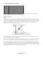
* Use 75°C copper wire or equivalent.
Determine the wire size for the main circuit so that line voltage drop is within 2% of the rated voltage. Line
IMPORTANT
voltage drop is calculated as follows:
Line voltage drop (V) =
WARNING
3 x wire resistance (Ω/km) x wire length (m) x current (A) x 10-3
Prior to removing any protective cover or wiring any part of the Drive, remove all power sources, including
main input power and control circuit power. Wait a minimum of 5 minutes after power removal, before
removing any cover. The charge lamp located within the Drive should be off prior to working inside. Even if
the charge lamp is off, one must measure the AC input, output, and DC Bus potential to insure safe levels
prior to resuming work. Failure to adhere to this warning may result in personal injury or death.
Electrical Installation 2 - 7
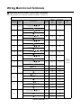
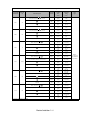
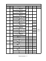
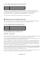
! Main Circuit Terminal Functions
Main circuit terminal functions are summarized according to terminal symbols in Table 2.3. Wire the terminals correctly for
the desired purpose.
Table 2.3 Main Circuit Terminal Functions (208-240Vac and 480Vac)
Purpose
Terminal Designation
Model: CIMR-P7U_ _ _ _
208-240Vac
480Vac
R/L1, S/L2, T/L3
20P4 to 2110
40P4 to 4300
R1/L11, S1/L21, T1/L31
2022 to 2110
4030 to 4300
Drive outputs
U/T1, V/T2, W/T3
20P4 to 2110
40P4 to 4300
DC power input
1,
20P4 to 2110
40P4 to 4300
Braking Transistor
Unit Connection
3,
2022 to 2110
4030 to 4300
Braking Resistor
Unit Connection
B1, B2
20P4 to 2018
40P4 to 4018
20P4 to 2018
40P4 to 4018
20P4 to 2110
40P4 to 4300
Main circuit power input
DC reactor connection
Ground
1,
2
Electrical Installation 2 - 8
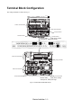
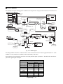
! Main Circuit Configurations 208-240Vac
The 208-240Vac main circuit configurations of the Drive are shown in Table 2.4.
Table 2.4 Drive Main Circuit Configurations
208-240Vac
CIMR-_ _ _ 2022 and 2030
(30 Hp to 40 Hp)
CIMR-_ _ _ 20P4 to 2018
(1/2 Hp to 25 Hp)
Note
1
{
Notes
1&3
Power
supply
{
Control
circuits
Power
supply
Control
circuits
CIMR-_ _ _ 2037 to 2110
(50 Hp to 150 Hp)
Notes
1&3
{
---
Power
supply
Control
circuits
Note1. Input fuses or molded case circuit breakers are required for proper branch circuit protection for all Drives. Failure
to use recommended fuses/circuit breakers (See Appendix E) may result in damage to the wiring, Drive and/or
personal injury.
2. Control power is supplied internally from the main circuit DC power supply for all Drives.
3. Consult your Yaskawa representative before using 12-pulse rectification.
Electrical Installation 2 - 9
! Main Circuit Configurations 480Vac
The 480Vac main circuit configurations of the Drive are shown in Table 2.5.
Table 2.5 Drive Main Circuit Configurations
480Vac
CIMR-_ _ _ 4030 to 4055
(40 Hp to 100 Hp)
CIMR-_ _ _ 40P4 to 4018
(1/2 Hp to 30 Hp)
Note
1
{
Notes
1&3
Power
supply
{
Control
circuits
Power
supply
Control
circuits
CIMR-_ _ _ 4075 to 4160 and CIMR-_ _ _ 4185 to 4300
(125 Hp to 500 Hp)
3
Notes
1&3
{
---
Power
supply
Control
circuits
Note1. Input fuses or molded case circuit breakers are required for proper branch circuit protection for all Drives. Failure
to use recommended fuses/circuit breakers (See Appendix E) may result in damage to the wiring, Drive and/or
personal injury.
2. Control power is supplied internally from the main circuit DC power supply for all Drives.
3. Consult your Yaskawa representative before using 12-pulse rectification.
Electrical Installation 2 - 10
Cable Length between Drive and Motor
The P7 should be installed as close as possible to the motor to minimize the length of load side power cable. If the cable
between the Drive and the motor is long, the high-frequency leakage current will increase, causing the Drive output current to
increase as well. This may affect peripheral devices. To prevent this, reduce the cable length whenever possible, or if
necessary, adjust the carrier frequency (set in C6-02) as shown in Table 2.6.
Table 2.6 Motor Cable Length vs. Carrier Frequency (C6-02)
Motor Cable Length
164 ft. (50m) maximum
328 ft. (100m) maximum
More than 328 ft.(100m)
Carrier Frequency
15kHz maximum
10kHz maximum
5kHz maximum
"Ground Wiring
Observe the following precautions when connecting the ground wire:
1. 208-240Vac Drives should have a ground connection with resistance of less than 100Ω.
2. 480Vac Drives should have a ground connection with resistance of less than 10Ω.
3. Do not share the ground wire with other devices, such as motors or large-current electrical equipment.
4. Always use a ground wire that complies with technical standards on electrical equipment and minimize the length of the
ground wire. Leakage current flows through the Drive. Therefore, if the distance between the ground rod and the ground
terminal is too long, potential on the ground terminal of the Drive will become unstable.
5. When using more than one Drive, be careful not to loop the ground wire. See Fig 2.2.
NOT OK
OK
NO
Fig 2.2 Ground Wiring Examples
" Control Circuit Ground Terminals
The removable Drive control terminal card provides two ground terminals (marked TB3 and TB4) to accept the control wire
shield connection. The control wire shield should be connected on this end only, the opposite end should be isolated with
electrical tape.
IMPORTANT
Grounding of the P7 enclosure and motor is required for proper system operation.
Electrical Installation 2 - 11
! Dynamic Braking Connections
"General
Dynamic braking (DB) enables the motor to be brought to a smooth and rapid stop. This is achieved by dissipating the
regenerative energy of the AC motor across the resistive components of the Dynamic Braking option. For further details on
dynamic braking operation, see the instruction sheet shipped with dynamic braking components.
Drives P7U20P4 thru P7U2018 and P7U40P4 thru P7U4018 have an integral braking transistor and require the addition of a
Remote Mounted Resistor Unit or a Heat Sink Mount Resistor (ERF). All higher rated Drives require the use of a Braking
Transistor Unit (CDBR) and a Remote Mount Resistor Unit.
Remote Mount Resistor Units typically mount outside of the electrical enclosure. Braking Transistor Units mount inside of the
electrical enclosure. Heat Sink Mount Resistors mount to the back of the Drive, attaching directly to the heat sink.
Table 2.7 Heat Sink Mount Dynamic Braking Resistor - 3% Duty Cycle
Drive
Rated
Input
Vac
208-240
480
Heat Sink Mount Resistor
Part No.
Qty.
Reqd.
Resistance
(Ohms)
Power
(Watts)
Approx.
Braking
Torque
(%)
20P4
R7505
1
200
150
20P7
R7505
1
200
21P5
R7504
1
22P2
R7503
23P7
Drive
Model No.
P7U
Dimensions (Inches)
Height
Width
Depth
220
7.16
1.73
0.51
150
125
7.16
1.73
0.51
100
150
125
7.16
1.73
0.51
1
70
150
120
7.16
1.73
0.51
R7510
1
62
150
100
7.16
1.73
0.51
40P4
R7508
1
750
150
230
7.16
1.73
0.51
40P7
R7508
1
750
150
130
7.16
1.73
0.51
41P5
R7507
1
400
150
125
7.16
1.73
0.51
42P2
R7506
1
115
150
115
7.16
1.73
0.51
43P7
R7505
1
200
150
110
7.16
1.73
0.51
"Installation
This option should only be installed by a technically qualified individual who is familiar with this type of equipment and the
hazards involved.
WARNING
Hazardous voltages can cause severe injury or death. Lock all power sources feeding the Drive in the “OFF” position.
Failure to follow these installation steps may cause equipment damage or personal injury.
Preliminary Procedures
1. Disconnect all electrical power to the Drive.
2. Remove Drive front cover.
3. Use a voltmeter to verify that voltage is disconnected from incoming power terminals and that the DC bus has dissipated.
Electrical Installation 2 - 12
Duty and HP
Braking Motor Voltage and
Power Rating
Duty
Required Dynamic Braking Units and Resistors
Typical Performance
Required Dynamic Resistance and
Additional Required Resistance and rms Peak Braking
Average
Braking Units:
rms Current Rating Dynamic Braking Units: Current Rating
Power
Braking Power
Standard
Duty:
150%
Peak
Braking
Power
15HP
20HP
25HP
30HP
40HP
230VAC 50HP
60HP
12%
75HP
Average
100HP
Braking
125HP
Power
150HP
1 of CDBR-2022B
1 of CDBR-2022B
2 of CDBR-2022B
2 of CDBR-2022B
2 of CDBR-2022B
1 of CDBR-2110B
1 of CDBR-2110B
1 of CDBR-2110B
1 of CDBR-2110B
1 of CDBR-2110B
2 of CDBR-2110B
9.00 ohm
6.80 ohm
9.00 ohm
9.00 ohm
6.80 ohm
2.10 ohm
2.10 ohm
1.60 ohm
1.60 ohm
1.60 ohm
1.60 ohm
12.0A
16.0A
12.0A
12.0A
16.0A
50.0A
50.0A
64.0A
64.0A and 1 of CDBR-2022B
64.0A and 2 of CDBR-2022B
64.0A
Heavy
Duty:
150%
Peak
Braking
Power
15HP
20HP
25HP
30HP
40HP
230VAC 50HP
60HP
50%
75HP
Average
100HP
Braking
125HP
Power
150HP
2 of CDBR-2022B
2 of CDBR-2022B
1 of CDBR-2110B
1 of CDBR-2110B
1 of CDBR-2110B
2 of CDBR-2110B
2 of CDBR-2110B
2 of CDBR-2110B
3 of CDBR-2110B
4 of CDBR-2110B
4 of CDBR-2110B
18.0 ohm
13.6 ohm
4.20 ohm
4.20 ohm
3.20 ohm
4.20 ohm
4.20 ohm
3.20 ohm
3.20 ohm
4.20 ohm
3.20 ohm
12.0A
16.0A
50.0A
50.0A
64.0A
50.0A
50.0A
64.0A
64.0A
50.0A
64.0A
‘Decel’
Duty:
150%
Peak
Braking
Power
1 of CDBR-2022B
1 of CDBR-2022B
2 of CDBR-2022B
2 of CDBR-2022B
2 of CDBR-2022B
1 of CDBR-2110B
1 of CDBR-2110B
1 of CDBR-2110B
1 of CDBR-2110B
1 of CDBR-2110B
2 of CDBR-2110B
9.00 ohm
6.80 ohm
9.00 ohm
9.00 ohm
6.80 ohm
2.10 ohm
2.10 ohm
1.60 ohm
1.60 ohm
1.60 ohm
1.60 ohm
09.2A
11.6A
09.2A
09.2A
11.6A
36.0A
36.0A
46.0A
46.0A and 1 of CDBR-2022B
46.0A and 2 of CDBR-2022B
46.0A
15HP
20HP
25HP
30HP
40HP
230VAC 50HP
60HP
6%
75HP
Average
100HP
Braking
125HP
Power
150HP
154% of 15HP
152% of 20HP
183% of 25HP
152% of 30HP
151% of 40HP
194% of 50HP
162% of 60HP
169% of 75HP
6.80 ohm 16.0A 156% of 100HP
6.80 ohm 16.0A 148% of 125HP
167% of 150HP
12.5% of 15HP
12.5% of 20HP
14.8% of 25HP
12.3% of 30HP
12.4% of 40HP
14.8% of 50HP
12.3% of 60HP
12.3% of 75HP
11.6% of 100HP
11.2% of 125HP
12.1% of 150HP
154% of 15HP
152% of 20HP
197% of 25HP
163% of 30HP
160% of 40HP
194% of 50HP
162% of 60HP
169% of 75HP
189% of 100HP
153% of 125HP
167% of 150HP
49.8% of 15HP
49.9% of 20HP
60.0% of 25HP
49.9% of 30HP
46.5% of 40HP
59.4% of 50HP
49.4% of 60HP
49.1% of 75HP
55.0% of 100HP
46.8% of 125HP
48.6% of 150HP
154% of 15HP
152% of 20HP
183% of 25HP
152% of 30HP
151% of 40HP
194% of 50HP
162% of 60HP
169% of 75HP
6.80 ohm 11.6A 156% of 100HP
6.80 ohm 11.6A 148% of 125HP
167% of 150HP
Fig 2.3 230V Rated Braking Transistor and Resistor Units
Electrical Installation 2 - 13
7.3% of 15HP
6.6% of 20HP
8.7% of 25HP
7.2% of 30HP
6.5% of 40HP
7.7% of 50HP
6.4% of 60HP
6.3% of 75HP
6.0% of 100HP
5.8% of 125HP
6.3% of 150HP
Duty and HP
Motor Voltage
Braking
and Power Rating
Duty
Required Dynamic Braking Units and Resistors
Typical Performance
Required Dynamic Resistance and
Additional Required Resistance and rms Peak Braking
Average
Braking Units:
rms Current Rating Dynamic Braking Units: Current Rating
Power
Braking Power
Standard
Duty:
1 of CDBR-4045B
1 of CDBR-4045B
2 of CDBR-4045B
2 of CDBR-4045B
2 of CDBR-4045B
1 of CDBR-4220B
1 of CDBR-4220B
1 of CDBR-4220B
1 of CDBR-4220B
1 of CDBR-4220B
2 of CDBR-4220B
2 of CDBR-4220B
3 of CDBR-4220B
18.0 ohm
13.6 ohm
18.0 ohm
18.0 ohm
13.6 ohm
4.20 ohm
4.20 ohm
3.20 ohm
3.20 ohm
3.20 ohm
3.20 ohm
4.20 ohm
3.20 ohm
12.1A
16.0A
12.1A
12.1A
16.0A
50.0A
50.0A
64.0A
64.0A and 1 of CDBR-4045B
64.0A and 2 of CDBR-4045B
64.0A
50.0A and 1 of CDBR-4220B
64.0A
Heavy
Duty:
2 of CDBR-4045B
2 of CDBR-4045B
1 of CDBR-4220B
1 of CDBR-4220B
1 of CDBR-4220B
2 of CDBR-4220B
2 of CDBR-4220B
2 of CDBR-4220B
3 of CDBR-4220B
4 of CDBR-4220B
4 of CDBR-4220B
5 of CDBR-4220B
6 of CDBR-4220B
36.0 ohm
27.2 ohm
8.40 ohm
8.40 ohm
6.40 ohm
8.40 ohm
8.40 ohm
6.40 ohm
6.40 ohm
8.40 ohm
8.40 ohm
8.40 ohm
6.40 ohm
12.1A
16.0A
50.0A
50.0A
64.0A
50.0A
50.0A
64.0A
64.0A
50.0A
50.0A
50.0A
64.0A
‘Decel’
Duty:
1 of CDBR-4045B
1 of CDBR-4045B
2 of CDBR-4045B
2 of CDBR-4045B
2 of CDBR-4045B
1 of CDBR-4220B
1 of CDBR-4220B
1 of CDBR-4220B
1 of CDBR-4220B
1 of CDBR-4220B
2 of CDBR-4220B
2 of CDBR-4220B
3 of CDBR-4220B
18.0 ohm
13.6 ohm
18.0 ohm
18.0 ohm
13.6 ohm
4.20 ohm
4.20 ohm
3.20 ohm
3.20 ohm
3.20 ohm
3.20 ohm
4.20 ohm
3.20 ohm
08.5A
11.6A
08.5A
08.5A
11.0A
36.0A
36.0A
46.0A
46.0A and 1 of CDBR-4045B
46.0A and 2 of CDBR-4045B
46.0A
50.0A and 1 of CDBR-4220B
46.0A
30HP
40HP
50HP
60HP
150%
75HP
Peak
100HP
Braking
Power 480VAC 125HP
150HP
200HP
250HP
12%
300HP
Average
Braking
400HP
Power
500HP
30HP
40HP
50HP
60HP
150%
75HP
Peak
100HP
Braking
480VAC 125HP
Power
150HP
200HP
250HP
50%
300HP
Average
Braking
400HP
Power
500HP
30HP
40HP
50HP
60HP
150%
75HP
Peak
100HP
Braking
480VAC 125HP
Power
150HP
200HP
250HP
6%
Average
300HP
Braking
400HP
Power
500HP
152% of 30HP
151% of 40HP
182% of 50HP
151% of 60HP
159% of 75HP
192% of 100HP
153% of 125HP
167% of 150HP
13.6 ohm 16.0A 154% of 200HP
13.6 ohm 16.0A 146% of 250HP
166% of 300HP
3.20 ohm 64.0A 156% of 400HP
148% of 500HP
12.5% of 30HP
12.4% of 40HP
14.9% of 50HP
12.4% of 60HP
13.0% of 75HP
14.7% of 100HP
11.7% of 125HP
12.1% of 150HP
11.5% of 200HP
11.1% of 250HP
12.0% of 300HP
11.7% of 400HP
10.7% of 500HP
152% of 30HP
151% of 40HP
194% of 50HP
162% of 60HP
169% of 75HP
192% of 100HP
153% of 125HP
167% of 150HP
187% of 200HP
152% of 250HP
126% of 300HP
118% of 400HP
148% of 500HP
50.1% of 30HP
49.4% of 40HP
59.4% of 50HP
49.4% of 60HP
49.1% of 75HP
58.8% of 100HP
46.8% of 125HP
48.6% of 150HP
54.4% of 200HP
46.3% of 250HP
38.5% of 300HP
36.0% of 400HP
42.9% of 500HP
152% of 30HP
151% of 40HP
182% of 50HP
151% of 60HP
159% of 75HP
192% of 100HP
153% of 125HP
167% of 150HP
13.6 ohm 11.6A 154% of 200HP
13.6 ohm 11.0A 146% of 250HP
166% of 300HP
3.20 ohm 46.0A 156% of 400HP
148% of 500HP
Fig 2.4 480V Rated Braking Transistor and Resistor Units
Electrical Installation 2 - 14
6.2% of 30HP
6.5% of 40HP
7.4% of 50HP
6.1% of 60HP
6.2% of 75HP
7.6% of 100HP
6.1% of 125HP
6.3% of 150HP
6.0% of 200HP
5.6% of 250HP
6.2% of 300HP
9.5% of 400HP
5.5% of 500HP
Heat Sink Mount Resistor Installation
1. Remove the Drive from its mounting for access to the rear of the heat sink.
2. Attach the Heat Sink Mount Resistor on the back of the Drive’s heat sink with screws M4 x 10mm (0.7mm pitch), as shown
in figure below.
3. Remove the rubber plug and run the braking resistor wires into the hole that leads to the terminal block.
4. Reinstall the Drive in its mounting position.
5. Connect the leads from the Heat Sink Mount Resistor to the Drive terminals B1 and B2.
6. Proceed to “Adjustments” section on page 2-20.
Fig 2.5 Attaching Heat Sink Mount Resistor on Heat Sink
Electrical Installation 2 - 15
Remote Mount Resistor Unit Installation Using Internal Braking Transistor
(for P7U20P4 thru P7U2018 and P7U40P4 thru P7U4018)
Since the Remote Mount Resistor Unit generates heat during dynamic braking operation, install it in a location away from
other equipment.
1. Install the Remote Mount Resistor Unit to a non-combustible surface, maintaining a minimum 1.97 inches (50mm)
clearance on each side and a minimum 7.87 inches (200mm) clearance on top.
2. Remove the Remote Mount Resistor Unit cover to access its terminal block. Connect the Remote Mount Resistor Unit to the
Drive and to external control circuitry according to Fig 2.6 below.
Table 2.8 Wire Size for Remote Mount Resistor Unit
Terminals
B, P, R1, R2
1, 2*
Wire Size (AWG)
12-10
18-14*
Wire Type
600V Ethylene propylene rubber insulated, or equivalent
Terminal Screw
M4
* Power Leads for the Remote Mount Resistor Unit generate high levels of electrical noise - these signal leads must be grouped separately.
IM
S3
SN
3% DUTY CYCLE
RESISTOR ASSEMBLY
(R2)*
(R1)*
120 VAC
*
Terminal markings in parentheses
are for resistors manufactured by
Powerohm Resistors Inc.
Fig 2.6 Wiring Remote Mount Resistor Unit (for P7U20P4 thru P7U2018 and P7U40P4 thru P7U4018)
3. Reinstall and secure Remote Mount Resistor Unit cover and Drive front cover.
4. Proceed to “Adjustments” section on page 2-20.
Electrical Installation 2 - 16
Braking Transistor Unit(s) and Remote Mount Resistor Unit(s) Installation (for P7U2022 thru P7U2110 and
P7U4022 thru P7U4300)
Since the Remote Mount Resistor Unit generates heat during dynamic braking operation, install it in a location away from
other equipment.
Select Mounting locations for Braking Transistor Unit(s) and Remote Mount Resistor Unit(s) so that wiring between the Drive
and the (Master) Braking Transistor Unit, and between each Braking Transistor Unit and its associated Remote Mount
Resistor Unit, is less than 33 feet (10m).
1. Mount the Braking Transistor Unit(s) on a vertical surface. The Braking Transistor Unit requires a minimum of 1.18 inches
(30mm) clearance on each side and a minimum 3.94 inches (100mm) clearance top and bottom. Attach the Remote Mount
Resistor Unit maintaining a minimum 1.97 inches (50mm) clearance on each side and a minimum 7.87 inches (200mm)
clearance on top.
2. In each Braking Transistor Unit, set the nominal line voltage jumper plug to the correct setting for the installation; this is
factory set at the 230V/460V position. To access jumper plugs, remove the Plexiglas cover.
3. If multiple Braking Transistor Units are being installed, the unit closest to the Drive should have the Slave/Master jumper
plug set to the “Master” position (factory setting); all others must have this jumper plug set to the “Slave” position.
4. If a single Braking Transistor Unit and Remote Mount Resistor Unit are being installed, connect them to the Drive and
external control circuitry according to the chart and figure below.
5. Power leads for the Remote Mount Resistor Unit generate high levels of electrical noise - these power leads must be
grouped separately.
Table 2.9 Wire Size for Remote Mount Resistor Unit and Braking Transistor Unit
Name
Braking Transistor Unit
(Models CDBR-2015B,
-2022B, -4030B, -4045B)
Braking Transistor Unit
(Model CDBR-2045, -4090)
Braking Transistor Unit
(Model CDBR-2110)
Circuit
Main
Control
Main
Control
Braking Transistor Unit
(Model CDBR-4220)
1
4
s
2
5
3
6
s
r
1
4
2
5
3
6
Wire Type
Terminal Screw
600V vinyl sheathed wire
or equivalent
M4
18-14 (0.75-2)
12-10 (3.5-5.5)
18-14 (0.75-2)
600V vinyl sheathed wire
or equivalent
600V vinyl sheathed wire
or equivalent
B
P
12-10 (3.5-5.5)
Control
1
2
18-14 (0.75-2)
*1 For wire size of 8-6 (8-14), use UL1283 heat-resistant vinyl-insulated wire or equivalent.
*2 M4 for Models LKEB-20P7 to -27P5 or -40P7 to -4015.
M5 for Models LKEB-2011 to -2022 or -4018 to -4045.
Electrical Installation 2 - 17
M4
M4
M6
600V vinyl sheathed wire
or equivalent
18-14 (0.75-2)
Main
M5
M6
18-14 (0.75-2)
4 (22)
8-6 (8-14) *1
12-10 (3.5-5.5)
P, Po, N, B
Main
12-10 (3.5-5.5)
4 (22)
8-6 (8-14) *1
12-10 (3.5-5.5)
P, Po, N, B
r
Control
Braking Resistor Unit
(Model LKEB-! )
0
0
1
2
3
4
5
6
P, Po, N, B
1
2
3
4
5
6
Main
Control
Wire Size AWG (mm2)
Terminals
600V vinyl sheathed wire
or equivalent
M4
M4
(M5) *2
M4
IM
S3
SN
0
R1
0
R2
REMOTE
MOUNT
RESISTOR
UNIT
Fig 2.7 Wiring Single Braking Transistor Unit and Remote Mount Resistor Unit to Drive
(P7U2022 thru P7U2110 and P7U4022 thru P7U4300)
Electrical Installation 2 - 18
6. If two or more Braking Transistor Units and Remote Mount Resistor Units are being installed, connect them to the Drive
and to external circuitry according to Fig 2.8.
IM
SN
S3
R1 R2
0
0
0
0
0
0
R1 R2
R2
0
R1
0
R1 R2
0
0
R1 R2
0
0
Note: Connect only the number of braking transistor units and remote mount resistor units required for the application.
Fig 2.8 Wiring Multiple Braking Transistor Units and Remote Mount Resistor Units to Drive
(P7U2022 thru P7U2110 and P7U4022 thru P7U4300)
Electrical Installation 2 - 19
Adjustments
7. All Drives: Program Parameter L3-04 to “0” or “3” to disable stall prevention during deceleration.
8. Heat Sink Mount Resistor Only: Program L8-01 to “1” to enable overheat protection for heat sink mount braking
resistor.
Operation Check
9. During dynamic braking, verify that the “BRAKE” lamp inside the Braking Unit is lit. This lamp illuminates only when
dynamic braking is activating (during quick deceleration).
10. During dynamic braking, ensure that the required deceleration characteristic is obtained. If not, contact Yaskawa for
assistance.
11. Reinstall and secure covers on the Braking Transistor Units, Remote Mount Resistor Units, and the Drive.
Electrical Installation 2 - 20
Control Wiring
! Control Circuit Wire Sizes
The auto mode speed reference (speed command) field wiring connection is made to P7 Drive terminals A1 or A2 (signal
positive), AC (signal common) and G (shield). Keep this lead length as short as possible to maintain signal quality. Insulated
twisted shielded pair wire (2 conductor # 18 ga, Belden 8760 or equivalent) is required. Do not run these wires in the same
conduits as other AC power or control wires. The shield must be connected on this end only, stub and isolate the other end.
The A2 signal employed is 4 to 20 mA with parameter H3-08 set for “2: 4 - 20 mA”. For 0 to 10 VDC, parameter H3-08 is set
for “0: 0 - 10 VDC” and the P7 control board DIP switch S1-2 must be in the OFF position. (See Figure 2.9)
For remote operation, keep the length of the control wiring to 50m or less. Separate the control wiring from high-power lines
(input power, motor leads or relay sequence circuits) to reduce noise induction from peripheral devices.
When setting speed commands (frequency references) from an external speed potentiometer (and not from the Digital Operator), use shielded twisted-pair wires and ground the shield to terminal E(G), as shown in Fig 2.9. Terminal numbers and wire
sizes are shown in Table 2.10.
E
(G)
E(G)
+V
20mA
+V +15VDC,
+15VDC, 20mA
2k
2k Ω
2k
2k
External
External
Frequency
Frequency
Reference
Reference
A1
Ω)
A10-10VDC
0- 10VDC (20k
(20K Ω)
to 20m
44 to
20mAA
P
P
E7
Drive
A2
H3-08
A2 H308
4-20m
A (250K
(250KΩΩ)
4- 20mA
)
[0[0toto+10V
Ω)]
+10V (20K
(20K Ω
)]
AC
AC
P
P
(P=Pair)
Signal
Terminal Connections
0-10Vdc
A1 to AC
4-20mA
or
0-10Vdc
A2 to AC
Fig 2.9 Analog Input Terminal Configuration
Table 2.10 Terminal Numbers and Wire Sizes (Same for all Drives)
Terminals
Terminal
Screws
Tightening
Torque
lb-in
(N•m)
Possible
Wire Sizes
AWG (mm2)
Recommended
Wire Size AWG
(mm2)
S1, S2, S3, S4, S5, S6, S7
SN, SC, SP, +V, A1, A2,
AC, MI, M2, M3, M4,
MA, MB, MC, FM, AC,
AM, R+, R-, S+, S-, IG
Phoenix
type *3
4.2 to 5.3
(0.5 to 0.6)
Stranded
wire:
26 to 16
(0.14 to 1.5)
18
(0.75)
E(G)
M3.5
7.0 to 8.8
(0.8 to 1.0)
20 to 14
(0.5 to 2*2)
12
(1.25)
Wire Type
• Shielded, twisted-pair wire*1
• Shielded, polyethylene-covered,
vinyl sheath cable
*1.Use shielded twisted-pair cables to input an external speed command.
*2.Yaskawa recommends using straight solderless terminals on digital inputs to simplify wiring and improve reliability.
*3. Yaskawa recommends using a thin-slot screwdriver with a 3.5 mm blade width.
Electrical Installation 2 - 21
! Wiring Checks
After all wiring is completed, perform the following checks:
1. Is all wiring correct?
2. Have all wire clippings, screws or other foreign material been removed from the Drive enclosure?
3. Are all terminal screws tight?
Electrical Installation 2 - 22
! Control Circuit Terminal Functions
The factory default functions of the control circuit terminals for 2-wire control are shown in Table below.
Type
No.
S1
S2
S3
Digital
input
signals
Analog
input
signals
Fault when CLOSED.
External fault input
Fault reset
Reset when CLOSED
S5
Multi-step speed reference 1
(Master/auxiliary switch)
S6
Multi-step speed reference 2
Auxiliary frequency reference
when CLOSED.
Multi-step setting 2 when
CLOSED.
S7
SN
Jog frequency reference
Digital input supply common
SC
SP
Digital input photocoupler
Digital input supply +24Vdc
+V
+15Vdc power output
+15Vdc power supply for analog inputs or transmitters
+15Vdc
(Max. current: 20 mA)
A1
Analog input or
Speed Command
0 to +10Vdc/100%
0 to +10 V(20 kΩ)
A2
Multi-function analog input
AC
Analog common
E(G)
Shield wire, optional ground
line connection point
M2
M3
M4
MA
MB
Functions set by
H1-01 to H1-05.
Refer to Table 2.14 for connection details.
Function set by
H3-09.
–
During Run
(N.O. contact)
CLOSED during operation
Remote/Auto Operation
(N.O. contact)
CLOSED when local control
RS-485/
422
Multi-function analog output
AC
Analog common
AM
Multi-function analog output
R+
Modbus
communication input
RS+
SIG
Modbus
communication output
Signal common
(output frequency)
0 to +10Vdc/100% frequency
Multi-function
digital output
Function set by
H2-01.
Multi-function
digital output
Function set by
H2-02.
Electrical Installation 2 - 23
Dry contacts
Contact capacity:
1 A max. at 250Vac
1 A max. at 30Vdc
0 to +10Vdc max. ±5%
2 mA max.
Multi-function
analog monitor 2
Function set by
H4-04
For 2-wire RS-485, jumper R+ and S+ and
jumper R- and S-.
-
Dry contacts
Contact capacity:
1 A max. at 250Vac
1 A max. at 30Vdc
Multi-function
analog monitor 1
Function set by
H4-01
–
(output current)
0 to +10Vdc/100% Drive's rated
output current
4 to 20 mA(250Ω)
0 to +10 V(20kΩ)
–
–
MA/MC: CLOSED during fault condition
MB/MC: OPEN during fault condition
FM
24 Vdc, 8 mA
Photocoupler isolation
Jog frequency when CLOSED.
4 to 20 mA/100%
0 to +10Vdc/100% (H3-0
–
Fault output signal
(SPDT)
Multi-function
digital inputs
MC
Analog
output
signals
Signal Level
S4
M1
Digital
output
signals
Table 2.11 Control Circuit Terminals
Signal Name
Description
Forward run/stop command
Forward run when CLOSED; stopped when OPEN.
Reverse run/stop command
Reverse run when CLOSED; stopped when OPEN.
Differential input,
PHC isolation
Differential input,
PHC isolation
-
! DIP Switch S1
DIP Switch S1 is described in this section. The functions of DIP switch S1 are shown in Table 2.12.
S1
O
1
Terminating
resistance
1
2
DIP Switch S1 located on
terminal board.
Fig 2.10 DIP Switch S1 Location
Table 2.12 DIP Switch S1
Name
S1-1
S1-2
Function
Setting
OFF: No terminating resistance
RS-485 and RS-422 terminating resistance ON: Terminating resistance of 110Ω
Factory Default = OFF
Input method for analog input A2
OFF: 0-10 Vdc (internal resistance: 20KΩ)
ON: 4-20mA (internal resistance: 250Ω)
Factory Default = ON
Electrical Installation 2 - 24
! Shunt Connector CN15
The shunt connector CN15 is described in this section. Shunt connector along with parameters H4-07 and H4-08 select the
signal range of the analog output terminals FM and AM.
Shunt connector CN15 is only available when the optional Terminal Card with the 4-20mA Analog Output Monitor is installed
(Model No. ETC61812_). See Chapter 7, Maintenance, for installation of the optional Terminal Card.
The function of various shunt connector CN15 configurations is shown in Table 2.13.
Fig 2.11 Shunt Connector CN15 Location
Table 2.13 Shunt Connector CN15 Configuration Options
CN15
Analog Output Monitor Configurations
Voltage Output (0-10Vdc) for terminals FM-AC (CH1) and AM-AC (CH2)
Current Output (4-20mA) for terminals FM-AC (CH1) and AM-AC (CH2)
Voltage Output (0-10Vdc) for terminals FM-AC (CH1)
Current Output (4-20mA) for terminals AM-AC (CH2)
Current Output (4-20mA) for terminals FM-AC (CH1)
Voltage Output (0-10Vdc) for terminals AM-AC (CH2)
The software configuration for the analog output monitor signal type is listed below:
Parameter
No.
Parameter Name
Description
Digital Operator Display
Setting
Range
Factory
Setting
Menu
Location
H4-07
Terminal FM Signal Level
Selection
AO Level Select1
0: 0 - 10 V
2: 4-20 mA
0 or 2
0
Programming
H4-08
Terminal AM Signal Level
Selection
AO Level Select2
0: 0 - 10 V
2: 4-20 mA
0 or 2
0
Programming
Electrical Installation 2 - 25
! Sinking/Sourcing Mode
The input terminal logic can be switched between sinking mode (0V common) and sourcing mode (+24V common) by using
the terminals SN, SC, and SP. An external power supply can also be connected, providing more freedom in signal input
methods.
Table 2.14 Sinking/Sourcing Mode and Input Signals
Internal Power Supply – Sinking Mode
External Power Supply – Sinking Mode
External +24V
(Factory Default)
Internal Power Supply – Sourcing Mode
External Power Supply – Sourcing Mode
External +24V
Electrical Installation 2 - 26
! Terminal Connections
Connections to Drive terminals are shown.
Braking terminals only on
CIMR-P7U 20P4 to 2018
CIMR-P7U 4030 to 4300
B1
Fig 2.12 Terminal Connections
Electrical Installation 2 - 27
B2
! Control Circuit Wiring Precautions
Observe the following precautions when wiring control circuits:
1.
2.
3.
4.
5.
6.
Separate control wiring from power/motor wiring (terminals R/L1, S/L2, T/L3, U/T1, V/T2, W/T3, ,
1, 2, and
3) and other high-power lines.
Separate wiring for control circuit terminals MA, MB, MC, M1, M2, M3, and M4 (digital outputs) from wiring to other
control circuit terminals.
If using an optional external power supply, ensure it is a UL Listed Class 2 power supply source.
Use twisted-pair or shielded twisted-pair cables for control circuits to prevent operating faults. Prepare cable ends as
shown in Figure below.
Connect the shield wire to terminal E(G).
Insulate the shield with tape to prevent contact with other signal lines and equipment.
Shield sheath
Insulation
Do not connect here.
Connect to shield sheath
terminal E(G) at Drive
Insulate with tape
Fig 2.13 Preparing the Termination of Shielded Twisted-pair Cables
Electrical Installation 2 - 28
! Field Wiring Diagram
Use this diagram to document field wiring. It may be helpful to copy this page.
+ 1
+ 2
+ 3
-
P7
R/L1
S/L2
B1
B2
U/T1
V/T2
T/L3
W/T3
MA
S1
MB
S2
MC
S3 (H1-01)
S4 (H1-02)
M1
S5 (H1-03)
(H2-01)
S6 (H1-04)
M2
M3
S7 (H1-05)
(H2-02)
SN
M4
SC
SP
E(G)
E(G)
+V +15VDC, 20mA
A1 0-10VDC, 20 K Ω
A2 (H3-08)
4-20mA, 250 KΩ
[0 to +10VDC, 20KΩ ]
AC
(H4-01) FM
(H4-04) AM
Terminating
Resistance
110
AC
R+
S1-1
RS+
S-
IG
Fig 2.14 Field Wiring Diagram
Electrical Installation 2 - 29
Electrical Installation 2 - 30
Chapter 3
Digital Operator
This chapter describes the displays and functions of the Digital Operator.
Digital Operator Display.......................................................3-2
Digital Operator Keys ..........................................................3-3
Drive Mode Indicators..........................................................3-4
Drive Main Menu .................................................................3-6
Quick Setting Menu (-QUICK-) .......................................... 3-11
Programming Menu (-ADV-) ..............................................3-12
Example of Changing a Parameter ...................................3-14
Digital Operator 3 - 1
Digital Operator Display
The Digital Operator is used for programming, operating, monitoring, and copying the Drive’s parameters. To copy parameters,
both Drives must have the same software version, model, and control method. The various items included on the Digital
Operator are described below.
Drive Mode Indicators
See Table 3.2
Menu Display
-DRIVE-
Frequency Ref
U1-01=
Rdy
60.00Hz
Ready Display
Drive can operate when a Drive command is input
-----------------------------
U1-02=
U1-03=
60.00Hz
10.05A
Data Display
Displays monitor data, parameter data and settings
1 line x 13 characters
3 lines x 16 characters
Key Descriptions
See Table 3.1
RUN & STOP Indicators
Example of Data Display
Factory Default
Setting
-QUICKC o n t r o l M e t ho d
--------------------------------A 1 - 0 2 = 3 *3*
Flux Vector
See Tables 3.5 and 3.6
Currently Programmed Value
“2”
Present Selection (User adjusts)
Fig 3.1 Digital Operator Component Names and Functions
Digital Operator 3 - 2
Digital Operator Keys
The names and functions of the Digital Operator Keys are described in Table 3.1.
Table 3.1 Digital Operator Keys
Key
Name
Function
LOCAL / REMOTE
• Switches between operation via the Digital Operator (LOCAL) and the settings in
parameter b1-01 (Frequency Reference Selection) and b1-02 (Run Command
Selection) (REMOTE).
• This key can be enabled or disabled by the setting in parameter o2-01.
• The Drive must be in a stopped condition before it can be transferred to “LOCAL”
or “REMOTE” mode.
• Scrolls through the five main menus:
MENU
• Operation (-DRIVE-), Quick Setting (-QUICK-), Programming (-ADV-),
Modified Constants (-VERIFY-), and Auto-Tuning (-A.TUNE-).
ESCAPE
JOG
FWD / REV
INCREASE
DECREASE
• Returns to the previous display, before the DATA/ENTER key was
pressed.
• Enables jog operation when the Drive is being operated from the Digital
Operator (LOCAL).
• Selects the rotation direction of the motor when the Drive is being operated
from the Digital Operator (LOCAL).
• Increases parameter numbers and set values.
• Used to move to the next item or data value.
• Decreases parameter numbers and set values.
• Used to move to the previous item or data value.
• Selects the digit to be changed. The selected digit will blink.
SHIFT/RESET
• Also resets the Drive when a fault has occurred. The run command must be
removed before the reset command will be accepted.
DATA/ENTER
RUN
• Enter menus and parameters as well as to set values.
• Starts Drive operation when the Drive is being controlled by the Digital Operator
(LOCAL).
• Stops Drive operation.
STOP Key
• This key can be enabled or disabled when operating from the external
terminal or communications by setting user parameter o2-02.
Digital Operator 3 - 3
Drive Mode Indicators
The definition of the Drive mode indicators are shown in Table 3.2.
Table 3.2 Drive Mode Indicators
Indicator
Definition
FWD
Lit when a forward run command is input.
REV
Lit when a reverse run command is input.
REMOTE SEQ
See Table 3.3.
REMOTE REF
See Table 3.4.
ALARM
Lit when a fault has occurred. Flashes when an Alarm has occurred.
! REMOTE Sequence (SEQ) Indicator
The status of the “REMOTE” Sequence (SEQ) indicator is shown in Table 3.3. This indicator is always “Off” when the Drive
is in the “LOCAL” mode. When the Drive is in the “REMOTE” mode, the SEQ indicator status is dependent on the setting of
parameter b1-02 (Run Command Selection). See Table 3.3.
Table 3.3 REMOTE Sequence (SEQ) Indicator
Indicator Status
Condition
On
Parameter b1-02 (Run Command Selection) is set to terminal strip, communications, or an option
board as indicated below:
b1-02 =1 (Terminals)
=2 (Communications)
=3 (Option PCB)
Off
Parameter b1-02 (Run Command Selection) is set to Digital Operator as indicated below:
b1-02=0 (Operator)
Digital Operator 3 - 4
! REMOTE Reference (REF) Indicator
The status of the “REMOTE” Reference (REF) indicator is shown in Table 3.4. This indicator is always “Off” when the Drive
is in the “LOCAL” mode. When the Drive is in the “REMOTE” mode, the REF indicator status is dependent on the setting of
parameter b1-01 (Frequency Reference Selection). See Table 3.4.
Table 3.4 REMOTE Reference (REF) Indicator
Indicator Status
Condition
Parameter b1-01 (Frequency Reference Selection) is set to terminal strip, communications, option
board, or pulse train as indicated below:
b1-01 =1 (Terminals)
=2 (Communications)
=3 (Option PCB)
=4 (Pulse Train)
On
Parameter b1-01 (Frequency Reference Selection) is set to digital
operator as indicated below:
b1-01=0 (Operator)
Off
! Run Indicator
The status of the “RUN” indicator is shown in Table 3.5 when the Drive is in either the “LOCAL” or “REMOTE” mode.
Table 3.5 RUN Indicator
Indicator Status
Condition
On
Drive is running.
Blinking
Drive is decelerating to a stop.
Off
Drive is stopped.
! Stop Indicator
The status of the “STOP” indicator is shown in Table 3.6 when the Drive is in either the “LOCAL” or “REMOTE” mode.
Table 3.6 STOP Indicator
Indicator Status
On
Blinking
Off
Condition
Drive is decelerating to a stop or stopped.
Drive is in a run condition but the frequency reference is less than the
minimum output frequency E1-09, or the Drive is running in “REMOTE” mode and the “STOP”
key on has been pressed.
Drive is running.
Digital Operator 3 - 5
Drive Main Menu
The Drive’s parameters and monitoring functions are organized into menu groups that make it easier to read and set
parameters. The Drive is equipped with five menu selections. The five selections and their primary functions are shown in
Table 3.7 and are directly available by pressing the menu key.
Table 3.7 Drive Main Menu
Main Menu
Operation
- DRIVE -
Primary Function(s)
The Drive can be run in this menu.
Use this menu for monitoring values such as frequency reference or output current, displaying fault history or displaying the fault traces.
Quick Setting
- QUICK -
The Drive can be programmed in this menu.
Use this menu to set/read the most commonly used parameters.
Programming
- ADV -
The Drive can be programmed in this menu.
Use this menu to set/read every parameter.
Modified Constants
- VERIFY Auto-Tuning
- A.TUNE -
The Drive can be programmed in this menu.
Use this menu to set/read the parameters that have been modified from their factory default settings.
The Drive can be programmed in this menu.
Use this menu to auto-tune the Drive in order to optimize motor control as well as utilize the bi-directional
speed search feature.
Digital Operator 3 - 6
! Main Menu Structure
The menu selection display will appear when the MENU key is pressed from a monitor or setting display. While viewing the
menu selection display, press the MENU key repeatedly to scroll between the menu selections. Press the DATA/ENTER key to
enter the desired menu selection.
MENU
-DRIVE** Main Menu **
-------------Operation
MENU
-DRIVE** Main Menu **
-------------Quick Setting
MENU
-DRIVE** Main Menu **
-------------Programming
MENU
-DRIVE** Main Menu **
-------------Modified Consts 1
MENU
-DRIVE** Main Menu **
-------------Auto-Tuning
MENU
1
Modified Consts = Modified Parameters
Fig 3.2 Main Menu Structure
Digital Operator 3 - 7
! Operation Menu (-DRIVE-)
This menu is used for setting a speed command or monitoring values such as output frequency and output current. It is also
used for displaying the fault history and the fault traces. The Drive must be in this menu in order to run, see parameter
b1-08.
IMPORTANT
Leaving the Drive in a menu other than the Operation Menu, will prohibit the Drive from running. While
running, if the Drive is in a menu other than “Operation” and the run command is removed and re-applied,
the Drive will stop and will not start until the Operation Menu is selected .
U1 Monitor List
Follow the key operations below (Fig.3.3) to access the Operation Menu:
-DRIVE-
-DRIVERdy
Frequency Ref
U1-01=
0.00Hz
** Main Menu **
-------------Operation
x1
--------------------
U1-02=
U1-03=
0.00Hz
0.00A
Fig 3.3 U1 Monitor List Access Procedure
Use
and
keys to scroll through the U1 “Monitor” parameter list. See Appendix A for functional description.
Table 3.8 U1 Monitor List
Monitor
Monitor
U1-01
Frequency Ref
U1-20
SFS Output (Soft Starter Signal)
U1-02
Output Freq
U1-24
PI Feedback
U1-03
Output Current
U1-28
CPU ID
U1-06
Output Voltage
U1-29
kWh
U1-07
DC Bus Voltage
U1-30
MWh
U1-08
Output kWatts
U1-34
OPE Detected
U1-10
Input Term Sts
U1-36
PI Input
U1-11
Output Term Sts
U1-37
PI Output
U1-12
Int Ctl Sts 1
U1-38
PI Setpoint
U1-13
Elapsed Time
U1-39
Transmit Err
U1-14
FLASH ID
U1-40
FAN Elapsed Time
U1-15
Term A1 Level
U1-51
Auto Mode Fref
U1-16
Term A2 Level
U1-52
Hand Mode Fref
U1-18
Mot SEC Current (Secondary Current)
U1-53
PI Feedback 2
Digital Operator 3 - 8
"U2 Fault Trace List
After viewing the “Monitor” parameter list, in order to view the “Fault Trace” parameter list, follow the key operations below
(Fig.3.4).
-DRIVERdy
Monitor
U1-01=
0.00Hz
-DRIVERdy
Fault Trace
U2-01=
None
-DRIVERdy
Current Fault
U2-01=
None
--------------------
--------------------
--------------------
U1-02=
U1-03=
0.00Hz
0.00A
U2-02=
U2-03=
None
0.00Hz
Fig 3.4 U2 Fault Trace List Access Procedure
Use
and
keys to scroll through the U2 “Fault Trace” parameter list.
Table 3.9 U2 Fault Trace List
Fault Trace Parameters
U2-01
Current Fault
U2-02
Last Fault
U2-03
Frequency Ref
U2-04
Output Freq
U2-05
Output Current
U2-07
Output Voltage
U2-08
DC Bus Voltage
U2-09
Output kWatts
U2-11
Input Term Sts
U2-12
Output Term Sts
U2-13
AC Drive Status
U2-14
Elapsed Time
Digital Operator 3 - 9
U2-02=
U2-03=
None
0.00Hz
" U3 Fault History List
After viewing the “Fault Trace” parameter list, in order to view the “Fault History” parameter list, follow the key operations
below Fig. 3.5).
-DRIVERdy
Fault Trace
U2-01=
None
-DRIVERdy
Fault History
U3-01=
None
-DRIVERdy
Last Fault
U3-01=
None
--------------------
--------------------
--------------------
U2-02=
U2-03=
None
0.00A
U3-02=
U3-03=
None
None
Fig 3.5 U3 Fault History Access Procedure
Use
and
keys to scroll through the U3 “Fault History” parameter list.
Table 3.10 Fault History List
Fault History Parameters
U3-01
Last Fault
U3-02
Fault Message 2
U3-03
Fault Message 3
U3-04
Fault Message 4
U3-05
Elapsed Time 1
U3-06
Elapsed Time 2
U3-07
Elapsed Time 3
U3-08
Elapsed Time 4
U3-09
Fault Message 5
U3-10
Fault Message 6
U3-11
Fault Message 7
U3-12
Fault Message 8
U3-13
Fault Message 9
U3-14
Fault Message 10
U3-15
Elapsed Time 5
U3-16
Elapsed Time 6
U3-17
Elapsed Time 7
U3-18
Elapsed Time 8
U3-19
Elapsed Time 9
U3-20
Elapsed Time 10
Digital Operator 3 - 10
U3-02=
U3-03=
None
None
Quick Setting Menu (-QUICK-)
This menu is used to set/read the most commonly used parameters in the Drive. Follow the key operations below (Fig. 3.6) to
access the Quick Setting Menu:
-QUICK-
x2
-QUICKReference Source
** Main Menu **
-------------Quick Setting
--------------------
B1-01=
1
*1*
Terminals
“1”
Fig 3.6 Quick Setting Parameter Access Procedure
Use
and
keys to scroll through the “Quick Setting” parameter list.
Table 3.11 Quick Setting Parameter List
Parameter
Number
Parameter Name
Parameter
Number
Parameter Name
A1-00
b1-01
b1-02
b1-03
b1-04
b4-01
b5-01
b5-02
b5-03
b5-04
b5-06
b5-07
b5-08
b5-09
b5-10
b5-11
b5-12
b5-13
b5-14
b5-15
b5-16
b5-17
b5-18
b5-19
b5-20
b5-21
b5-22
b5-23
b5-24
b5-25
b5-26
b5-27
b5-28
Language Selection
Frequency Reference Selection
Run command Selection
Stopping Method Selection
Reverse Operation Selection
Delay-On Timer
PI Mode Selection
Proportional Gain Setting
Integral Time Setting
Integral Limit Setting
PI Output Limit
PI Offset Adjustment
PI Primary Delay Time
PI Output Level Selection
PI Output Gain Setting
PI Output Reverse Selection
PI Feedback Reference Missing Detection Selection
PI Feedback Loss Detection Level
PI Feedback Loss Detection Time
PI Sleep Function Start Level
PI Sleep Delay Time
PI Accel/Decel Time
PI Setpoint Selection
PI Setpoint Value
PI Setpoint Display Setting
PI Sleep Input Source
PI Snooze Level
PI Snooze Delay Time
PI Snooze Deactivation Level
PI Setpoint Boost Setting
PI Maximum Boost Time
PI Snooze Feedback Level
PI Feedback Square Root Ac Function Selection
b5-29
b5-30
b8-01
C1-01
C1-02
PI Square Root Gain
Output Square Root Monitor Selection
Energy Savings Control Selection
Acceleration Time 1
Deceleration Time 1
d2-01
d2-02
E1-01
E2-01
F6-01
H3-02
H3-03
H3-10
H3-11
L2-01
L2-02
L4-05
L4-06
L5-01
L5-03
L6-01
L6-02
L6-03
L8-11
o1-01
o1-05
o1-07
o1-08
o2-03
o2-05
o2-08
o3-02
Frequency Reference Upper Limit
Frequency Reference Lower Limit
Input Voltage Setting
Motor Rated Current
Operation Selection After Communication Error
Terminal A1 Gain Setting
Terminal A1 Bias Setting
Terminal A2 Gain Setting
Terminal A2 Bias Setting
Momentary Power Loss Detection Selection
Momentary Power Loss Ride-thru Time
Frequency Reference Loss Detection Selection
Frequency Reference Level at Loss Frequency
Number of Auto Restarts Attempts
Maximum Restart Time After Fault
Torque Detection Selection 1
Torque Detection Level 1
Torque Detection Time 1
Heatsink Cooling Fan Operation Delay Time
User Monitor Selection
LCD Brightness Adjustment
Second Line User Monitor Selection
Third Line User Monitor Selection
User Parameter Default Value
Frequency Operation Time Selection
Cumulative Operation Time Selection
Read Allowed Selection
Digital Operator 3 - 11
Programming Menu (-ADV-)
This menu is used to set/read every parameter in the Drive. Follow the key operations below (Fig. 3.7) to access the Programming Menu.
-ADV-
x3
** Main Menu **
-------------Programming
-ADVInitialization
--------------------
A1-00=
0
Select Language
Fig 3.7 Programming Menu Access Procedure
Use
,
see appendix A.
, and
keys to scroll through the “Programming” parameter group list. For complete parameter listing
Table 3.12 Programming
Parameter Group List
Parameter Group Functions
A1
A2
b1
b2
b3
b4
b5
b8
C1
C2
C4
C6
d1
d2
d3
d4
E1
E2
F6
H1
H2
H3
H4
H5
L1
L2
L3
L4
L5
L6
L8
n1
n3
o1
o2
o3
Initialization
User Parameters
Sequence
DC Braking
Speed Search
Delay Timers
PI Control
Energy Saving
Accel/Decel
S-Curve Acc/Dec
Torque Comp
Carrier Freq
Preset Reference
Reference Limits
Jump Frequencies
Sequence
V/F Pattern
Motor Setup
Com OPT Setup
Digital Inputs
Digital Outputs
Analog Inputs
Analog Outputs
Serial Com Setup
Motor Overload
PwrLoss Ridethru
Stall Prevention
Ref Detection
Fault Restart
Torque Detection
Hdwe Protection
Hunting Prev
High Slip
Monitor Select
Key Selections
COPY Function
Digital Operator 3 - 12
! Modified Constants Menu (-VERIFY-)
This menu is used to set/read the parameters that have been modified from their original factory default settings. Follow the
key operations below (Fig. 3.8) to access the Modified Constants Parameter Menu.
-VERIFY-
x4
** Main Menu **
-------------Modified Consts
SeeNote
Note 1 1
See
Fig 3.8 Modified Constants Menu Access Procedure
Note 1: If there are not any parameters that have been modified from their original factory default settings, then the display
will state “None Modified”. Otherwise, use the “increase” and “decrease” keys to scroll through the “Modified
Constants” list.
! Auto-Tuning Menu (-A.TUNE-)
This menu is used to auto-tune the Drive in order to optimize motor control as well as utilize the bi-directional speed search
feature. Follow the key operations below (Fig. 3.9) to access the Auto-Tuning Menu.
-A.TUNE-
x5
-A.TUNEMtr Rated Power
** Main Menu **
-------------Auto-Tuning
--------------------
T1-02=
Fig 3.9 Auto-Tuning Menu Access Procedure
Use
and
0.40kW
(0.00~650.00)
“0.40kW”
keys to scroll through the “Auto-Tuning” parameter list.
Table 3.13 Auto-Tuning
Parameter List
Auto-Tuning Parameters
T1-02
Mtr Rated Power
T1-04
Rated Current
Digital Operator 3 - 13
Example of Changing a Parameter
Table 3.14 provides an example of how to change parameter “C1-02” (Deceleration Time 1) from 30 seconds to 40 seconds.
Table 3.14 Changing a Parameter in the Programming Menu
Step
Number
Digital Operator Display
1
-DRIVERdy
Frequency Ref
U1-01=
0.00Hz
Description
The Drive is first powered up.
--------------------
U1-02=
U1-03=
0.00Hz
0.00A
-DRIVE-
2
** Main Menu **
-------------Operation
Press the MENU key to scroll to “Operation” menu.
-QUICK-
3
** Main Menu **
-------------Quick Setting
Press the MENU key to scroll to “Quick Setting” menu.
-ADV-
4
** Main Menu **
-------------Programming
Press the MENU key to scroll to “Programming” menu.
-ADVInitialization
5
--------------------
A1-01=
0
Select Language
Press the DATA/ENTER key to enter “Programming” menu.
-ADVAccel/Decel
6
7
--------------------
C1-01=
1.0sec
Accel Time 1
-ADVAccel Time 1
--------------------
C1-01=
30.0sec
Press the INCREASE key until C1-01 (Accel/Decel) is displayed.
Press the SHIFT/RESET key to move flashing digit to the right.
(0.0~6000.0)
“30.0sec”
Digital Operator 3 - 14
Table 3.14 Changing a Parameter in the Programming Menu
Step
Number
Digital Operator Display
Description
-ADVDecel Time 1
8
--------------------
C1-02=
30.0sec
Press the INCREASE key to display C1-02 (Decel Time 1).
(0.0~6000.0)
“30.0sec”
9
-ADVDecel Time 1
--------------------
C1-02=
Press the DATA/ENTER key to access setting display.
0030.0sec
(0.0~6000.0)
“30.0sec”
10
-ADVDecel Time 1
--------------------
C1-02=
Press the SHIFT/RESET key to move the flashing digit to the right.
0030.0sec
(0.0~6000.0)
“30.0sec”
11
-ADVDecel Time 1
--------------------
C1-02=
0030.0sec
Press the SHIFT/RESET key to move the flashing digit to the right.
(0.0~6000.0)
“30.0sec”
12
-ADVDecel Time 1
--------------------
C1-02=
0040.0sec
Press the INCREASE key to increase the set data.
(0.0~6000.0)
“30.0sec”
-ADV-
13
14
Entry Accepted
-ADVDecel Time 1
--------------------
C1-02=
40.0sec
30.0sec
Press the DATA/ENTER key to enter the set data. “Entry Accepted” is displayed for 1.0 sec after the data setting has been confirmed.
The monitor display for C1-02 returns.
(0.0~6000.0)
“30.0sec”
-DRIVE-
15
16
** Main Menu **
-------------Operation
-DRIVERdy
Frequency Ref
U1-01=
0.00Hz
Press the MENU key to scroll to “Operation” menu.
Press the DATA/ENTER key to enter “Operation” menu.
--------------------
U1-02=
U1-03=
0.00Hz
0.00A
Digital Operator 3 - 15
Digital Operator 3 - 16
Chapter 4
Start Up
This chapter describes the procedures to prepare the Drive for start up and the
procedures to conduct a Drive start up.
Drive Start Up Preparation ................................................. 4-2
Drive Start Up Procedures ..................................................4-5
Start Up 4 - 1
Start Up
In order to provide the most reliable Drive available and to avoid any extra costs related to loss or reduction of warranty
coverage, an authorized Yaskawa service representative should complete this start up procedure. Please complete the
following checklist and maintain it in a secure location as technical service personnel may request information from this
checklist.
! DRIVE START UP PREPARATION
Date:
Start Up Person:
Company Name: _________________________________
Sales Order #: ___________________________________
Start Up Location: _________________________________
Serial #: ________________________________________
Printed Name: ___________________________________
Drive Location: ___________________________________
Phone #: _______________________________________
Signature: ________________________________________
Owners Representative:
Printed Name: ___________________________________
Phone #: _________________________________________
Company: ______________________________________
Signature: ________________________________________
Step
"
1. The Drive is thoroughly tested at the factory. The start up person should verify that the drive is free of shipping and
installation damage. Shipping damage is not covered by the Yaskawa warranty. Claims must be filed with the
shipping company as soon as possible for any potential recovery via insurance.
"
2. Review the User Manual shipped with the Drive.
"
3. Verify that the model number and voltage ratings in the purchase order match the nameplate data for each unit.
"
4. Location of the Drive is important to achieve proper performance and normal operating life. The unit should be
installed in an area where it is protected from:
$Direct sunlight, rain or moisture
$Corrosive gases or liquids
$Vibration, airborne dust or metallic particles
" 5.
Ensure the Drive is on a vertical surface with adequate space for air circulation (4.75” above and below, 1.2” on each
side). Refer to Fig 1.8.
" 6.
Verify that the proper branch circuit protection is installed in front of the Drive. Refer to Appendix E - Peripheral
Devices for proper input fuse or circuit breaker sizing.
Start Up 4 - 2
"
7.
Avoid running input and output wiring in the same conduit.
"
8.
Avoid routing power wiring near equipment sensitive to electrical noise.
"
9.
Never allow wire leads to touch metal surfaces. Short-circuit may result.
"
10. Never connect AC main power to output terminals U/T1, V/T2 and W/T3.
"
11. Never connect power factor correction capacitors or noise filters to the Drive output.
"
12. Use 600Vac vinyl-sheathed wire or equivalent. Wire size should be determined considering voltage drop of leads.
Line voltage drop (V) = 3 x wire resistance (Ω/km) x wire length (m) x current (A) x 10-3
"
13. It is recommended that the motor lead length not exceed 164 feet (50 meters) and motor wiring be run in a separate
conduit from the power wiring. If lead length must exceed this distance, reduce the carrier frequency (See Table 2.6)
and consult Yaskawa toll free at 1-800-YASKAWA (927-5292) for other motor protection measures.
"
14. Signal and control leads must be separated from main circuit leads (R/L1, S/L2, T/L3, U/T1, V/T2, W/T3).
"
15. Determine proper wire size for power and motor leads. Refer to Tables 2.1 and 2.2 for details.
"
16. Review proper ground connections for the Drive. Refer to Chapter 2 – Electrical Installation for details. The Drive
must be solidly grounded using the main circuit ground terminal. Ground resistance should be less than 100Ω for a
208-240Vac Drive. Ground resistance should be less than 10Ω for a 480Vac Drive. Select wire size suitable for the
size of terminal screw. Make the length as short as possible.
Never ground the drive in common with welding machines, motors or other large-current electrical equipment.
Where several Drives are used, ground each Drive directly or daisy-chain to the ground pole(s).
DO NOT FORM A LOOP WITH THE GROUND LEADS. See Figure 2.4.
"
17. Review terminal functions of signal and control circuits. Refer to Table 2.8.
"
18. Verify if any customer safety devices are required (e.g. firestat, freezestat, high static pressure).
"
19. Record the following motor nameplate information:
Voltage: _____________________Full Load Amps: ____________________
"
20. Verify that the commercial power supply is within the rated Drive input voltage:
Power Supply: ____________________VAC
Drive Input Voltage: ____________________VAC
"
21. Verify that the leads in the 3-Phase electric motor conduit box are configured for the proper voltage.
"
22. Ensure Motor Rated Current is less than or equal to Drive Output Amps. If multiple motors are being used, make
sure that the Motor Rated Current sum is less than or equal to Drive Output Amp rating. Please note that if multiple
motors are being operated from one Drive, each motor must have its own overload and short circuit protection.
Start Up 4 - 3
" 23. Wire all necessary power leads to the Drive. DO NOT CONNECT MOTOR TO DRIVE YET.
" 24. Wire all necessary ground wires to the Drive.
" 25. Wire all necessary control wires to the Drive.
" 26. Ensure that the power leads are connected to the R/L1, S/L2 and T/L3 terminals in the Drive.
" 27. Tighten all of the three-phase power and ground connections. Please check that all control and signal terminations are
tight.
" 28. Inspect the control circuit connections (including the shield) and determine if a motor “safety circuit” is connected.
If normally closed, these contacts may be wired in series with the RUN command contacts, which are between
terminals S1 and SN of the Drive. No special programming is required. Refer to Chapter 2 – Electrical Installation
(Fig. 2.7).
Alternately, these contacts could be wired between terminals S3 and SN as External Fault Inputs, and may be either
normally closed or normally open contacts.
" 29. Record any other connections to the Drive using the blank terminal connection drawing in Chapter 2 – Electrical
Installation (Fig. 2.9) to determine if special programming is required for the following:
•Multi-function Inputs – refer to Appendix A – Parameter List
•Multi-function Outputs – refer to Appendix A – Parameter List
•Multi-function Digital Inputs – refer to Appendix A – Parameter List
•Multi-function Analog Outputs – refer to Appendix A – Parameter List
•Serial Communications – refer to Appendix A – Parameter List
THIS COMPLETES THE DRIVE START UP PREPARATION.
Start Up 4 - 4
DRIVE START UP PROCEDURES
1.
Confirm that all three phases are present and that the input voltage is correct for the Drive being set up.
Measure the voltage on the line side of the Drives Molded Case Circuit Breaker/disconnect and record below.
Table 4.1 Input Voltage Check
Measurement Location
Voltage (Vac)
L1 – L2
L2 – L3
L1 – L3
WARNING
Use extreme caution when performing measurements as contact with live parts may result in personal injury
or death.
2.
If voltage level is within Drive Specification (See Appendix C - Specification), APPLY POWER to energize the
Drive. The STOP, AUTO SEQ and AUTO REF indicators should be on.
3.
REMOVE POWER from the Drive. Wait for the Red CHARGE LED (near the power terminals)
to go out.
4.
Connect the motor leads to the Drive at terminals U/T1, V/T2 and W/T3.
WARNING
The internal capacitor remains charged even after the power supply is turned off. The status indicator LED’s
and the digital operator display will be estinguished when the DC bus voltage is below 50VDC. To prevent
electric shock, wait at least 5 minutes after all indicators are off and measure the DC Bus voltage level to
confirm a safe level prior to working on the Drive.
5. APPLY POWER to the Drive.
6.
Set the Drive to Local control. Press the MENU key once to display the Operation menu. Then, press DATA/
ENTER to display “Frequency Reference”. Press the LOCAL/REMOTE key once. This puts the Drive in the Local
Mode, allowing run/stop and speed commands by the Digital Operator. The AUTO SEQ and AUTO REF indicators
turn off, and the FWD light turns on.
7.
Press the OFF key.
8. Press the MENU key two times. Press the DATA/ENTER key once to enter the Quick Setting Menu. Press the ▼
key 25 times to display parameter E1-01 “Input Voltage”. This parameter selects the nominal input voltage the Drive
will receive. To set this parameter for the application. Press the DATA/ENTER key once. Use the S, ▼ , and X keys
and the DATA/ENTER key to set this parameter per the application.
Table 4.2 Input Voltage Setting
Parameter
No.
E1-01
Parameter Name
Digital Operator Display
Input Voltage Setting
Input Voltage
Setting Range
Factory Setting
155.0 to 255.0
(208-240Vac)
240.0
(208-240Vac)
310.0 to 510.0
(480Vac)
480.0
(480Vac)
Menu Location
Quick Setting
or
Programming
Ensure the DATA/ENTER key is pressed to enter the selection in the Drive. “Entry Accepted” briefly appears and
the display is now no longer flashing.
Start Up 4 - 5
9.
Press the S key once to display E2-01 “Motor Rated FLA”.
This parameter is the foundation of motor protection. It can be entered when auto-tuning is performed. Set this
parameter according to the motor rated current (FLA). Press the DATA/ENTER key once. Use the S, ▼ , and X
keys to adjust E2-01 to the motor rated full load amps.
Table 4.3 Motor Rated Current
Parameter
No.
Parameter Name
Digital Operator Display
Setting
Range
Factory
Setting
Menu
Location
E2-01
Motor Rated Current
Motor Rated FLA
kVA
Dependent
kVA
Dependent
Quick Setting
or
Programming
Ensure the DATA/ENTER key is pressed to enter the value in the Drive. “Entry Accepted” briefly appears and your
display is now flashing.
10. Press the ESC once. Press DATA/ENTER once. Press S key twice to display b1-02 “Run Source”. This parameter
selects where the Drive will receive the run command. Press the DATA/ENTER key once. Use the S or ▼ keys and
the DATA/ENTER key to set this parameter for the application.
Table 4.4 Run Command Selection
Parameter
No.
Parameter Name
Digital Operator Display
b1-02
Run Command Selection
Run Source
Setting Choices
0:
1:
2:
3:
Operator
Terminals
Serial Com
Option PCB
Setting
Range
Factory
Setting
Menu Location
0-3
1
Quick Setting
or
Programming
Ensure the DATA/ENTER key is pressed to enter the selection in the Drive. “Entry Accepted” briefly appears and
the display is now not flashing.
11. Press the ▼ key once to display b1-01 “Reference Source”. This parameter selects where the Drive will receive the
speed command. Press the DATA/ENTER key once. Use the S or ▼ keys and the DATA/ENTER key to set this
parameter for the application.
Table 4.5 Speed Command Selection
Parameter
No.
Parameter Name
Digital Operator Display
b1-01
Frequency Reference
Selection
Reference Source
Setting
Choices
0: Operator
1: Terminals
2: Serial Com
3: Option PCB
Setting
Range
Factory
Setting
Menu Location
0-3
1
Quick Setting
or
Programming
Ensure the DATA/ENTER key is pressed to enter the selection in the Drive. “Entry Accepted” briefly appears and
the display is now not flashing.
12. Press the S key twice to display b1-03 “Stopping Method”.
This parameter selects the stopping method used when a stop command is given to the Drive.
Start Up 4 - 6
Table 4.6 Stopping Method Selection
Parameter
No.
Parameter Name
Digital Operator Display
b1-03
Stopping Method Selection
Stopping Method
Setting Choices
0:
1:
2:
3:
Ramp to Stop
Coast to Stop
DCInj to Stop
Coast w/Timer
Setting
Range
Factory Setting
Menu Location
0-3
0
Quick Setting
or
Programming
Press the DATA/ENTER key once. Use the ! or # keys to select the stopping method. Ensure the DATA/ENTER
key is pressed to enter the selection in the Drive. “Entry Accepted” briefly appears and the display is not flashing.
" 13. Press the MENU key once to display “Operation”.
" 14. Press the DATA/ENTER key once to display “Frequency Ref”.
" 15. The STOP and FWD lights are on.
" 16. Press the DATA/ENTER key once to enable entering of a speed command in U1-01. Use the ! and # keys to set a
speed command of 6.00Hz.
" 17. Press the RUN key once to start the motor and verify correct motor rotation for the application. The RUN light turns
on and the STOP light turns off.
If the direction of motor rotation is wrong, press the STOP key. The RUN light turns off and the STOP light turns on.
REMOVE POWER from the Drive. Wait for the Red CHARGE LED (near the power terminals) to go out. When it
does, swap the motor wires connected to terminals U/T1 & V/T2 in the Drive. Be sure to re-tighten the terminal lugs.
APPLY POWER.
To verify the motor rotation is now correct for the application, press the RUN key once to start the motor. The FWD
light turns on and the motor will rotate at the speed entered in step 16.
Start Up 4 - 7
" 18. Press the MONITOR key to display the U1 monitors. Use the ! and # keys to view Output Current (U1-03),
Output Voltage (U1-06), and DC Bus Voltage (U1-07) while running the Drive throughout its entire speed range.
Record the following information at each speed:
Frequency
(Hz)
Monitor U1-01
Output Current
(A)
Monitor U1-03
Output Voltage
(VAC)
Monitor U1-06
DC Bus Voltage
(VDC)
Monitor U1-07
6.0
10.0
15.0
20.0
25.0
30.0
35.0
40.0
45.0
50.0
55.0
60.0
When this table is complete, press the STOP key. The Drive will stop and the FWD light remains on. This step
provides benchmark data for the application from the initial start up.
" 19. Press the MENU key once to display “Operation”. Press the DATA/ENTER key to display “Frequency Ref”.
If using a remote speed command, press the LOCAL/REMOTE key so the REMOTE SEQ and REMOTE REF
indicators are on. This puts the Drive in Remote mode.
" 20. If using an external speed command, determine whether the speed command is a 0-10Vdc or a 4-20mA signal.
Connect the positive side of a 0-10Vdc signal to terminal A1. Connect the positive side of a 4-20mA signal to
terminal A2. Connect the COMMON of the speed command to terminal AC.
Note: Connect only one input. The factory default is 0-10Vdc. To change to 4-20mA adjust parameter H3-08
to “2:4 – 20mA” and ensure DIP Switch S1-2 (located on the terminal board) is in the ON position.
Start Up 4 - 8
" 21. Check the signal for proper polarity. Observe if the speed command can achieve the minimum and maximum speeds
desired. If not, perform the following:
For 0-10Vdc input (Terminal A1)
1. With no input, adjust Bias (H3-03 setting) until an output of “0.0 Hz” is obtained.
2.
With full-scale input, adjust Gain (H3-02 setting) until an output of “60.0 Hz” (or other desired maximum
frequency) is obtained.
For 4-20mA input (Terminal A2)
1. With 4mA input, adjust Bias (H3-11 setting) until an output of “0.0 Hz” is obtained.
2. With 20 mA input, adjust Gain (H3-10 setting) until an output of “60.0 Hz”
(or other desired maximum frequency) is obtained.
THIS COMPLETES THE DRIVE START UP PROCEDURE.
Start Up 4 - 9
Notes:
Start Up 4 - 10
Chapter 5
Basic Programming
This Manual contains descriptions of all user accessible parameters contained in the Drive.
Parameters are listed in alpha-numerical order. Parameter number and name, along with a
detailed description and its settings are described on the following pages.
A1 Initialization.................................................................................. 5-2
b1 Sequence..................................................................................... 5-4
b2 DC Braking .................................................................................. 5-9
b3 Speed Search .............................................................................5-11
b5 PI Function................................................................................. 5-15
b8 Energy Savings.......................................................................... 5-24
C1 Accel/Decel ............................................................................... 5-25
d2 Reference (Speed Command) Limits......................................... 5-26
d3 Jump Frequencies ..................................................................... 5-27
E1 V/f Pattern ................................................................................. 5-28
E2 Motor Setup............................................................................... 5-31
F6 Com OPT Selection ................................................................... 5-32
H3 Analog Inputs ............................................................................ 5-33
L2 Momentary Power Loss Ride-thru Function............................... 5-39
L3 Stall Prevention.......................................................................... 5-40
L4 Speed Command Loss Detection .............................................. 5-43
L5 Fault Restart .............................................................................. 5-44
L6 Torque Detection........................................................................ 5-46
L8 Hardware Protection .................................................................. 5-48
o1 Monitor Configuration ................................................................ 5-50
o2 Key Selections ........................................................................... 5-54
o3 Digital Operator Copy Function ................................................. 5-56
T1 Auto-Tuning ............................................................................... 5-59
Programming 5 - 1
Basic Programming Parameters
The initialization group contains parameters associated with initial set-up of the Drive. Parameters involving the display
language, access levels, initialization and password are located in this group.
! A1 Initialization
" A1-00 Select Language
Setting
0
1
2
3
4
5
6
Description
English (factory default)
Japanese
Deutsch
Francais
Italiano
Espanol
Portugues
The setting of parameter A1-00 determines which international language the Drive will use to display non-numerical text. The
A1-00 parameter will not be changed by an Initialization of the drive (A1-03= “1110: User Initialize”, “2220: 2-Wire Initial”,
or “3330: 3-Wire Initial”).
If the Drive is accidentally set to a language unfamiliar to the operator, locating the parameter to change the operator language
can be done by performing the following:
1. Press the MENU key until the “-ADV-” MENU is shown in the upper left corner of the digital operator.
2. Press the DATA/ENTER key to enter the programming menu. The first parameter shown is A1-00 (Select Language).
3. Press the DATA/ENTER key again and use the INCREASE and DECREASE arrow keys to choose the preferred language
from the list below:
0 : English
1 : Japanese
2 : Deutsch (German)
3 : Francais (French)
4 : Italiano (Italian)
5 : Español (Spanish)
6 : Portugu s (Portuguese)
" A1-01 Access Level Selection
Setting
0
1
2
Description
Operation Only
User Level
Advanced Level (factory default)
A1-01 can be used to allow access to and permission to change all Drive parameters. If the Drive is programmed for Operation
Only (A1-01= “0: Operation Only”), then only the OPERATION and the PROGRAMMING menus are accessible. Within the
PROGRAMMING menu only parameters A1-01 and A1-04 are adjustable.
Programming 5 - 2
If A1-01 is configured for Advanced Access (A1-01= “2: Advanced Level”), then all menus and all parameters are shown. If the
Access Level Selection is set to Advanced, all parameters should be adjustable unless:
1. The Drive parameters are password protected (A1-04) which will prevent access to A1-00 through A1-03 and all A2 parameters.
2. A digital input has been configured as a Program Lockout (H1-0X= 1B) is active.
3. During serial communication writing, if a parameter change is also attempted via the digital operator, a
“BUSY - WRITE PROTECTED” message will display. Parameter change will not be possible from the digital operator until
an Enter command is received via the serial communication to finish the serial writing process.
" A1-03 Initialize Parameters
Setting
0
1110
2220
3330
Description
No Initialize (factory default)
User Initialize
2-Wire Initialize
3-Wire Initialize
The Drive can be set back to one of three default states via the A1-03 parameter.
1. User Initialization – 1110: The modified Drive parameters are returned to the values selected as user settings. User settings are
stored when parameter o2-03= “1: Set Defaults”.
2. 2-Wire Initialization – 2220: The Drive parameters are returned to factory default values with digital inputs S1 and S2
configured as Forward Run and Reverse Run, respectively.
3. 3-Wire Initialization – 3330: The Drive parameters are returned to factory default values with digital inputs S1, S2, and S5
configured as Run, Stop, and Forward/Reverse respectively.
After an initialization is performed, parameter A1-03 will automatically be set back to 0.
S1
FWD Run/Stop
Stop
switch
(NC contact)
Operation
switch
(NO contact)
Run command
(run on momentary close)
S2
REV Run/Stop
S3 or S5
SN
SN
2-wire control
2-wire control
3-wire control
Stop command
(stop on momentary open)
Forward/reverse command
(multi-function input)
Sequence input common
Fig. 1 2 & 3-Wire Control Wiring Examples
IMPORTANT
Some parameters are unaffected by either the 2-Wire or 3-Wire initialization. The following parameters
will not be reset when parameter A1-03=2220 or 3330:
A1-00
E1-03
o2-04
o2-09
Language Selection
V/f Pattern Selection
kVA Selection
Initialization Specification Selection
Programming 5 - 3
! b1 Sequence
The Sequence Group contains parameters associated with starting and stopping the Drive. Parameters involving the Run
Command, Speed Reference location, Stopping Method and Hand/Auto changeover are located in this group.
" b1-01 Reference (Speed Command) Source Selection
Setting
0
1
2
3
Description
Operator - Digital Preset Speed d1-01
Terminals - Analog Input Terminal A1 (or Terminal A2, see Parameter H3-13)
Serial Com - RS-485 Terminals R+, R-, S+ and SOption PCB - Option Board connected at 2CN
In order to run the Drive and motor, the Drive must receive a Run command and a speed command. Parameter b1-01 specifies
from where the speed command is received when in the “Auto mode. Switching into the “Auto” mode can be done by pressing
the AUTO button on the digital operator while the Drive is stopped.
IMPORTANT
If a Run command is input to the Drive but no corresponding speed command is input, the Run indicator on
the digital operator will turn on and the STOP indicator on the digital operator will blink.
If you want the Drive to follow the speed command set by the digital operator: Use the “Hand” mode by pressing the hand
key or set b1-01= “0: Operator”. The speed command can then be entered into the U1-01 monitor parameter in the “-DRIVE-”
Menu.
If you want the Drive to follow an “Auto” analog speed command: Set b1-01= “1: Terminals”, and connect a 0 – 10 Vdc
speed command signal between terminals A1 and AC or a 4 – 20 mA speed command signal to terminals A2 and AC.
If you want the Drive to receive the speed command from serial communication: Set b1-01= “2: Serial Com”, and connect
the RS-485/422 serial communications cable to terminals R+, R-, S+, and S- on the control I/O terminal block.
If you want to use LONWORKS® to input a speed command: Set b1-01= “3: Option PCB”, and plug a LONWORKS®option
board (p/n SI-J) into the 2CN port on the Drive Control PCB. Consult the manual supplied with the option board for instructions
on integrating the Drive into the LONWORKS® System.
IMPORTANT
If b1-01= ”3: Option PCB” but a LONWORKS® card is not installed in 2CN, an OPE05 Operator Programming
Error will be displayed on the digital operator and the Drive will not run.
" b1-02 Run Source
Setting
0
1
2
3
Description
Operator
Terminals (factory default)
Serial Com
Option PCB
Programming 5 - 4
To successfully operate the Drive remotely, an external run command must be received by the Drive. Parameter b1-02
specifies from where the run command will be accepted.
Although the Run Source and the Reference Source (b1-01) are normally taken from the same source (e.g. digital operator,
terminals or serial communication), this is not always the case.
To issue a run command from the digital operator: Set b1-02= “0: Operator”, and use the HAND and OFF buttons to start
and stop the Drive.
To issue the run command from the terminals: Set b1-02= “1: Terminals”, and select between 2-wire and 3-wire control
operation by doing the following:
2-Wire Control The factory default setting is for 2-wire operation. In the 2-wire configuration a closure between S1 and SN
will be interpreted as a Forward Run command by the Drive. A closure between S2 and SN will be interpreted as a Reverse
Run command. If both S1 and S2 are closed, the Drive will stop (decelerate to zero speed) and the digital operator will display an EF (external fault) alarm (Flashing).
S1
FWD Run/Stop
S2
REV Run/Stop
SN
Fig. 2 2-Wire Control
3-Wire Control When any of the multi-function digital input parameters, H1-01 through H1-05, is set to 0, terminals S1 and
S2 become Run and Stop, respectively. The multi-function digital input that was set to 0 will function as a Forward/Reverse
input for the Drive. When the Forward/Reverse input is open the Drive will run in the Forward direction and when the input is
closed, the Drive will run in the Reverse direction.
In 3-wire operation a momentary closure (> 50mS) of S1 will cause the Drive to run provided that S2 is held closed. The
Drive will stop anytime the S2-SN connection is broken. If the 3-wire configuration is implemented via a 3-wire Initialization
(A1-03= “3330: 3-Wire Initial”), then terminal S3 becomes the Forward/Reverse input.
Stop
switch
(NC contact)
Operation
switch
(NO contact)
Run command
(run on momentary close)
S3 or S5
SN
Stop command
(stop on momentary open)
Forward/reverse command
(multi-function input)
Sequence input common
Fig. 3 3-Wire Control
To issue a run command via serial communication: Set b1-02= “2: Serial Com” and connect the RS-485/422 serial communication cable to R+, R-, S+, and S- on the removable terminal block.
To issue the Run command via the LONWORKS® option card: Set b1-02= “3: Option PCB”, and plug a LONWORKS® option
board (p/n SI/J) into the 2CN port on the Control PCB. Consult the manual supplied with the option board for instructions on
integrating the Drive into your LONWORKS® System.
IMPORTANT
If b1-01= ”3: Option PCB” but a LONWORKS® card is not installed in 2CN, an “OPE05” operator programming
error will be displayed on the digital operator and the Drive will not run.
Programming 5 - 5
" b1-03 Stopping Method
There are four methods of stopping the Drive when the Run command is removed.
Setting
0
1
2
3
Description
Ramp to Stop (factory default)
Coast to Stop
DC Injection to Stop
Coast w/Timer
“0:Ramp to stop”: When the Run command is removed, the Drive will decelerate the motor to 0 rpm. The rate of
deceleration is determined by the active deceleration time. The factory default Decel Time is in parameter C1-02.
When the output frequency has dropped below the DC Injection Start Frequency in b2-01 (Default = 0.5HZ) DC current will
be injected in the motor at a level determined by b2-02 (50% Default). The DC Injection condition will occur for the time
specified by b2-04 (0.0 Default), to establish the end point of the ramp. DC injection can be used to insure the motor is at zero
rpm prior to the Drive shutting off.
ON (CLOSED)
Run Command
OFF (OPEN)
100 %
b2-01
Output Frequency
0%
Deceleration Time (C1-02)
DC Injection Brake
|
TIME
b2-04
|
Fig. 4 Deceleration to Stop
The actual deceleration time can be determined by the following formula
Time to Stop =
Output Freq. at time of stop command
02 or C1-04)
× Setting of active Decel Time (C1 - 02)
Maximum Frequency (E1 - 04)
If S-Curve characteristics are specified by the Drive programming, they will add to the total time to stop.
“1:Coast to stop”: When the Run command is removed, the Drive will turn off its output and the motor will coast
(uncontrolled deceleration). The friction of the driven equipment will eventually overcome any residual
inertia of the system and the rotation will stop.
ON (CLOSED)
Run Command
OFF (OPEN)
100 %
Motor Speed
Drive Output Frequency Interrupted
Output Frequency
0%
TIME
Fig. 5 Coast to Stop
Programming 5 - 6
IMPORTANT
After a stop is initiated, a subsequent Run commands input before the Minimum Baseblock Time (L2-03)
has expired, will be ignored.
2:DCInj to Stop: When the Run command is removed, the Drive will Baseblock (turn off its output) for the Minimum
Baseblock Time (L2-03). Once the Minimum Baseblock Time has expired, the Drive will inject DC current into the motor
windings to lock the motor shaft. The stopping time will be reduced as compared to Coast to Stop. The level of DC
Injection current is set by parameter b2-02 (50% Default). The DC Injection brake time is determined by the set value in
b2-04 and the output frequency at the time the Run command is removed.
DC Injection Brake Time =
(b2 - 04) × 10 × Output Frequency
Maximum Frequency (E1 - 04)
ON
(CLOSED)
Run Command
b2-04 x 10
100 %
Output Frequency
Drive Output Voltage Interrupted
DC Injection Brake Time
OFF
(OPEN)
b2-04
DC Injection Brake
0%
DC Injection Brake Time
b2-04
Minimum Baseblock
Time (L2-03)
100% (Maximum
Output Frequency)
10%
Fig. 6 DC Injection Braking to Stop
IMPORTANT
If an overcurrent (OC) fault occurs during DCInj to Stop, lengthen the Minimum Baseblock Time (L2-03)
until the fault no longer occurs.
3:Coast w/Timer: When the Run command is removed, the Drive will turn off its output and the motor will coast to a stop.
If a Run command is input before time T (operation wait time) expires, the Drive will not run and the Run command will
need to be cycled before operation can occur. The time T (operation wait time) is determined by the output frequency when
the Run command is removed and the active deceleration time (C1-02).
Ignored
Run Command
ON
(CLOSED)
Run Command
Deceleration
Time (C1-02)
100 %
Output Frequency
Drive Output
Voltage
Interrupted
Operation Wait Time (T)
OFF
(OPEN)
Minimum
Baseblock
Time (L2-03)
Minimum
Output
Frequency
0%
Timer Value
T Value T
Timer
(C1-02)
Fig. 7 Coast to Stop with Timer
Programming 5 - 7
100% (Maximum
Output
Frequency)
Output Frequency at Stop Command Input
" b1-04 Reverse Operation
Setting
0
1
2
3
Description
Reverse Enabled
Reverse Disabled (factory default)
Exchange Phase
ExchgPhs, Rev Dsbl
For some applications reverse motor rotation is not applicable and may even cause problems (e.g., air handling units,
pumps, etc.). Setting parameter b1-04 to 1 or 3 will cause the Drive to ignore any inputs for reverse operation. Setting
parameter b1-04 to either 2 or 3 will change the motor shaft rotation when a Forward Run command is given by exchanging
the order of the output phasing.
The factory default setting of parameter b1-04 is “1: Disabled”. When b1-04= “1: Disabled”, reverse operation is prohibited
and no exchanging of output phasing occurs.
Drive terminal S2 is a dedicated input for reverse Run/Stop.
" b1-07 Local/Remote Run Selection
Setting
0
1
Description
Cycle Extern Run (factory default)
Accept Extrn Run
When the Drive is switched between the Local (Hand) mode (the digital operator) to the Remote (Auto) mode (determined by
b1-01 and b1-02), there is the possibility that a Run command is already present (i.e. a contact closure between S1 and SN
when b1-02= “1: Terminals”). Parameter b1-07 determines whether the Drive will:
Ignore the external Run command until it is removed and re-instated (b1-07= “0: Cycle Extern Run”)
OR
Accept the already present Run command and immediately begin acceleration to the commanded speed
(b1-07= “1: Accept Extrn Run”).
IMPORTANT
When switching from local mode to Auto mode when b1-07=“1: Accept Extrn Run” the Drive may start
unexpectedly if the Run command is already applied. Be sure all personnel are clear of rotating machinery
and electrical connections prior to switching between local mode and Auto mode.
" b1-08 Run Command Selection During Programming
Setting
0
1
Description
Disabled (factory default)
Enabled
As a safety precaution, the Drive will not normally respond to a Run input when the digital operator is being used to adjust
parameters. If it is necessary that external Run commands be recognized even while the Drive is being programmed, set
b1-08= “1: Enabled”.
Programming 5 - 8
" b1-11 Drive Delay Time Setting
Setting Range: 0 to 600 Seconds
Factory Default: 0 Seconds
If a time is set into parameter b1-11, the Drive will delay executing any run command until the b1-11 time has expired.
During Drive delay time execution, the digital operator will display:
DDLY
Waiting to RUN
Both the ALARM and Run indicators will blink while the Drive waits to execute the Run command.
" b1-12 Hand Frequency Reference Selection
Setting
0
1
Description
Operator (factory default)
Terminals
When the Drive is put into the HAND mode, by pressing the HAND key while in Operation, the Speed Command will be set
via the digital operator by default. If it is desirable to have the Speed Command input from the terminals instead of the digital
operator, set b1-12= “1: Terminals”.
IMPORTANT
When the Speed Command is set via the terminals, parameter H3-13 will determine whether analog input
terminal A1 or A2 is the Speed Command.
! b2 DC Braking
The DC Braking Group contains parameters associated with the DC injection braking feature. Parameters involving the starting frequency, current level, braking time, and motor pre heat current level are located here.
" b2-01 DC Injection Braking Start Frequency
Setting Range: 0.0 to 10.0 Hz
Factory Default: 0.5 Hz
Parameter b2-01 sets the output frequency where the Drive begins DC Injection during Ramp to stop. in order to lock the rotor
of the motor and established the end point of the ramp. If b2-01 < E1-09 (Minimum Frequency), then DC Injection begins at
E1-09.
Parameter b2-01 also determines the output frequency that the Drive must be at or below before a Zero Speed condition is
considered true. This affects any digital output configured as a Zero Speed signal (H2-0x= “1: Zero Speed”).
Programming 5 - 9
DC injection
b2-01
Output Frequency
|
|
t ime
b2-04
Fig. 8 DC Injection Braking During Stopping
" b2-02 DC Injection Braking Current
Setting Range: 0 to 100%
Factory Default: 50%
The level of DC Injection Braking Current affects the strength of the magnetic field attempting to lock the motor shaft.
Increasing the level of current will increase the amount of heat generated by the motor windings and should only be increased
to the level necessary to hold the motor shaft. DC Injection current is set in percentage of Drive rated output current. Drive
rated output
current is stated on the Drive nameplate.
" b2-03 DC Injection Braking Time at Start
b2-04 DC Injection Braking Time at Stop
Setting Range: 0.00 to 10.00 Seconds
Factory Default: 0.00 Seconds
The Drive can be programmed to automatically DC Inject for a predetermined amount of time prior to accelerating to speed
(b2-03) and/or at the end of a Ramp to stop (b2-04). Parameter b2-03 can be used to stop a rotating motor prior to attempting
acceleration (i.e. a wind milling fan). If DC Injection braking at start or Speed Search is not enabled, attempting to drive a
spinning motor may cause nuisance tripping.
Parameter b2-04 can be used to resist any residual motion of the load after the deceleration has finished.
DC injection
Output Frequency
b2-03
b2-04
Fig. 9 DC Injection Braking During Starting and Stopping
Parameter b2-04 also serves the function of affecting the length of time DC Injection to stop (b1-03= “2: DC Injection to
Stop”) will occur.
Programming 5 - 10
" b2-09 Motor Pre-Heat Current
Setting Range: 0 to 100%
Factory Default: 0%
A DC current can be circulated within the motor windings while the motor is stopped. The current will produce heat within the
motor and prevent condensation. Parameter b2-09 determines the percentage of Drive rated output current that will be used for
the motor pre-heat function. This function can be useful in applications where the motor sits for extended periods of time in
humid conditions. Motor pre-heating can only be initiated by closing a digital input programmed as a Motor Pre-heat
Input (H1-0x= 60). Check with the motor manufacturer to determine the maximum acceptable current level the motor can
withstand when stopped. Be sure not to exceed the motor manufacturers recommended level.
! b3 Speed Search
The Speed Search function allows the Drive to determine the speed of a motor shaft that is being driven by rotational inertia.
Speed Search will allow the Drive to determine the speed of the already rotating motor and begin to ramp the motor to a set
speed without first having to bring it to a complete stop. When a momentary loss of supply power is experienced, the Drive
output is turned off. This results in a coasting motor. When power returns, the Drive can determine the speed of the coasting
motor and start without requiring it to be brought to minimum speed. Speed Search can be programmed to always be active by
setting b3-01 or it can be commanded by remote contact closure by setting a digital input.
There are two forms of Speed Search in the Drive, the speed estimation method and the current detection method.
IMPORTANT
When setting the Drive for remote Speed Search input, via a contact closure, the method of Speed Search
is determined by the setting of b3-01. If b3-01= ”0: SpdsrchF Disable” then the remote input will initiate
speed estimation method, and if b3-01= ”2: SpdsrchI Disable”, then the remote input will start the current
detection method.
Parameters L2-03 and L2-04 also affect the current detection method of Speed Search operation.
" b3-01 Speed Search Selection
This parameter is effective only when the Drive is given a new “RUN” command.
Setting
0
1
2
3
Description
SpdsrchF Disable
SpdsrchF Enable
SpdsrchI Disable (factory default)
SpdsrchI Enable
Speed Estimation: Method (b3-01= 0 or 1) The speed estimation method will calculate the speed using measurements of
residual motor fields. The speed estimation version is bi-directional and will determine both the motor speed and direction. To
enable speed estimation Speed Search at start, set b3-01= “1: SpdsrchF Enable”.
.
IMPORTANT
If the speed estimation method of Speed Search is to be used, then Auto-tuning must be performed prior to
using Speed Search. If the length of cable between the Drive and motor is ever changed after Auto-tuning
then Auto-tuning should be performed again.
Programming 5 - 11
IMPORTANT
The speed estimation mode cannot be used when there are multiple motors operated by one Drive or the
motor is two or more frames smaller than the standard size motor per the Drive capacity.
AC power supply
ON
OFF
Set frequency
reference
Start using
speed detected
Output frequency
Output current
10 ms
Minimum baseblock time (L2-03) x 0.75 *1
Minimum baseblock time (L2-03) x 0.75*1
*2
*1 Baseblock time may be reduced by the output frequency
immediately before the baseblock.
motor
waits
for the
*2 After AC power supply recovery, the
motor
waits
for the
minimum Speed Search Wait Time (b3-05).
Fig. 10 Speed Search (Estimated Speed Method) after momentary power loss where the power loss
time is less than the minimum baseblock time
AC power supply
ON
OFF
Start using speed detected
Set frequency
reference
Output frequency
Output current
10 ms
Minimum baseblock time
(L2-03)
Speed Search Wait Time
(b3-05)
Note: IfIf the
immediately
before
the baseblock
is low oristhe
supply
off time
is long,
Note:
thefrequency
frequency
immediately
before
the baseblock
lowpower
or the
power
supply
break time is long,
operation
may
be
the
same
as
the
search
in
case
1.
operation may be the same as the search in case 1.
Fig. 11 Speed Search (Estimated Speed Method) after momentary power loss where the power loss
time exceeds the minimum baseblock time
Current Detection Method (b3-01=2 or 3): The current detection method starts searching from a predetermined frequency
while monitoring the Drive output current to determine when the rotor speed and the Drive output speed (frequency) match.
The current detection version is not bi-directional. To enable current detection Speed Search at start set b3-01= “3: SpdscrhI
enable” and program any digital input equal to Speed Search 1 (H1-0x= 61) or Speed Search 2 (H1-0x= 62). Speed Search 1
will start searching from the max. frequency (E1-04) and ramp down to meet the rotor speed. Speed Search 2 will start searching from the set frequency and ramp down to meet the rotor speed.
IMPORTANT
If a UV1 fault occurs when current detection Speed Search is attempted, increase the setting of L2-04
Programming 5 - 12
IMPORTANT
If an OC fault occurs when Speed Search is attempted after power loss recovery, increase the setting of L2-03.
OFF
Run command
ON
Deceleration time set in b3-03
Maximum output
frequency or
set frequency
Set frequency
reference
Output frequency
b3-02 Speed search current level
Output current
Minimum baseblock time
(L2-03)
*
SearchTime
Delay
Time (b3-05).
* Lower limit is set using Speed Search
(b3-05).
Fig. 12 Speed Search (Current Detection Method) at Startup
AC power supply
ON
OFF
Output frequency before power loss
Set frequency
Deceleration
reference
time set in b3-03
Output frequency
b3-02
speed search operating current
Output current
*1 Baseblock time may be reduced by the output frequency
immediately before baseblock.
*2 After AC power supply recovery, motor waits for the minimum
Speed Search Wait Time (b2-03).
b3-05
Minimum baseblock time (L2-03) *1
*2
Fig. 13 Speed Search (Current Detection Method) after momentary power loss where the power loss
time is less than the minimum baseblock time
AC power supply
ON
OFF
Output frequency before power loss
Set frequency
Deceleration
Decelerationspeed
time set
setininb3-03
b3-03 reference
Output frequency
b3-02
Speed search operating time
Output current
Speed search wait time (b3-05)
Minimum baseblock time
(L2-03)
Fig. 14 Speed Search (Current Detection Method) after momentary power loss where the power loss
time exceeds the minimum baseblock time
Speed Search Settings and Methods
Setting of
b3-01
Automatic Speed Search
for all RUN commands
Automatic Speed Search after
momentary power loss and
baseblock
Speed Search Used for Run with
programmed multi-function
input
0
No
Yes - Speed Estimation
Yes - Speed Estimation
1
Yes - Speed Estimation
Yes - Speed Estimation
Yes - Speed Estimation
2
No
Yes - Current Detection
Yes - Current Detection
3
Yes - Current Detection
Yes - Current Detection
Yes - Current Detection
Programming 5 - 13
" b3-02 Speed Search Deactivation Current
Setting Range: 0 to 200% of Drive rated output current
Factory Default: 120% of Drive rated output current
When using the current detection method of Speed Search, parameter b3-02 sets the current level that will determine when the
search is complete and the rotor and output speeds match. When the output frequency is higher than the actual rotor speed the
slip causes the current to be high. As the output frequency is lowered, the closer it comes to the rotor speed, the lower the
current draw will be. When the output current drops below the level as set in b3-02 (100% = Drive Rated Current) the output
frequency stops decreasing and normal operation resumes.
" b3-03 Speed Search Deceleration Time
Setting Range: 0.1 to 10.0 Seconds
Factory Default: 2.0 Seconds
Parameter b3-03 sets the deceleration ramp used by the current detection method of Speed Search when searching for the
motor’s rotor speed. Even if Speed Search 2 is selected, for Speed Search at start, the time entered into b3-03 will be the time
to decelerate from maximum frequency (E1-04) to minimum frequency (E1-09).
" b3-05 Speed Search Delay Time
Setting Range: 0.0 to 20.0 Seconds
Factory Default: 0.2 Seconds
In cases where an output contactor is used between the Drive and the motor, extra waiting time is provided after power returns
and before Speed Search is performed. This extra time allows for the contactor to operate. When Speed Search at start is used,
b3-05 will serve as the lower limit of the Minimum Baseblock Time (L2-03).
" b3-14 Bi-Directional Speed Search Selection
Setting
0
1
Description
Disabled
Enabled (factory default)
The b3-14 parameter can be used to turn off the bi-directional capabilities of the Speed Estimation form of Speed Search. By
turning off the bi-directional capability, the speed search will only try to match the speed in the last known direction.
Programming 5 - 14
! b5 PI Function
The capability to accept an analog signal as feedback for a PI (Proportional + Integral) control function is built into the Drive.
D1-04
Frequency Reference
using multi-step
command
Sleep function
2 selection b5-21
1
+
0
-
D1-02
b1-01
4
D1-01
b5-01=0
Serial Com
1
0
PI Differential
Fdbk. H3-09=16
Sleep Function
Scaling
PI SFS cancel
H1-xx=34
1
2
b5-01=3
o1-03
Terminal A1
+
OFF
b5-01=1
+
1
MEMOBUS Reg. 06H
PI target value
PI control is OFF under the following ON
conditions:
- b5-01=0
- During JOG command input
- H3-xx=19
and the terminal status is
H1
ON
0
0
Output
frequency
b5-11
1
SFS
Lower limit 0
Upper limit
Fmax x109%
1
0
1
PI Differential
Fdbk. H3-09=16
0
b5-20
PI Set Point
(U1-38)
b5-18
Scaling
+
-
PI
b5-23 Snooze
Delay
b5-22
Timer
PI Snooze Level
PI Input
(U1-36)
0
PI Input
Characteristic
Caracteristic
H1-xx=35
0
+
-
Z-1
Terminal A1
1
PI Differential
Fdbk. H3-09=16
0
1
H3-09=B
PI Feedback
(U1-24)
Scaling
b5-20
+
1
0
1
-
1
b5-29
P
PI Differential
Fdbk. H3-09=16
PI Feedback 2
(U1-53)
PI Snooze Function
b5-20
PI SFS
b5-17
b5-28
0
Lower limit
Fmax x109%
Scaling
PI SFS cancel
H1-xx=34
1
0
Sleep function
selection b5-21
0 r o 1
2
Reg. 0Fh, bit 1
Constant b5-19
Terminal A2
Upper limit
Fmax x109%
0
PI SFS
b5-17
RUN
on/off
b5-16
Delay
Timer
b5-15
Sleep Level
Enable / Disable reverse operation
when PI output is negative
3
Option Card
1
Frequency reference
(U1-01)
1
P
0
+
1/t
Proportional 1
gain
b5-02 Integral Hold
H1-xx=31
+
PI delay time
b5-08
+ +
Integral Reset
H1-xx=30
+
1/t
PI Limit
b5-06
Sleep function
selection b5-21
2
+
1
PI Differential
Fdbk. H3-09=16
PI Snooze Function
+
-
0 or 1
PI
Wake Up
b5-24
PI Wake Up Level
b5-10
+
Z-1
1
Z -1
PI Output
Gain
0
1
PI Output
Characteristic
b5-09
1
PI Differential
Fdbk. H3-09=16
0 H3-09=16
+
0
I - limit
b5-04
I-time
b5-03
0
0
b5-07
PI offset
1
0
b5-30
PI output monitor
(U1-37)
PI offset
(b5-07)
Fig. 15 PI Block Diagram
The analog feedback to the Drive for the PI control is via the A2 terminal. The Drive must be programmed (H3-09= “B: PI
Feedback”) to use terminal A2 as feedback for the PI functionality of the Drive.
The PI setpoint can be configured to come from one of many different inputs or parameters. The table below describes the
options for originating the PI setpoint.
Table 1 PI Setpoint Options
If these conditions are true
Status of
The PI Setpoint
Modbus
Status of
Status of
will be read from:
Register
b5-18
b1-01
0Fh bit 1
Parameter b5-19
=1
N/A
N/A
Modbus Register
=0
ON
N/A
06H
D1-01
=0
OFF
=0
Terminal A1
=0
OFF
=1
Serial Comm.
=0
OFF
=2
Option PCB
=0
OFF
=3
Programming 5 - 15
In some situations there are two feedback inputs. The drive can be programmed to maintain a set differential between two
analog signals. If input A2 is configured as a “PI Differential Mode” (H3-09= “16: PI Differential”), then the Drive will maintain
a set difference between the measurements read on inputs A1 and A2. This differential setpoint is programmed by parameter
(b5-07).
" b5-01 PI Mode
Setting
0
1
3
Description
Disabled (factory default)
Enabled
Fref+PI
The Drive can be used as a stand-alone PI controller. If PI functionality is selected by parameter b5-01, the Drive will adjust its
output to cause the feedback from a transmitter to match the PI setpoint (b5-19). The setting of b5-01 will determine whether PI
functionality is disabled (b5-01= “0: Disabled”), enabled (b5-01= “1: Enabled”), or enable with the output of the PI function used
to trim a Speed Command (b5-01= “3: Fref+PI”).
" b5-02 Proportional Gain Setting
Setting Range: 0.00 to 25.00
Factory Default: 2.00
The proportional gain will apply a straight multiplier to the calculated difference (error) between the PI Setpoint and the
measured transmitter feedback at terminal A2. A large value will tend to reduce the error but may cause instability (oscillations)
if too high. A small value may allow to much offset between the setpoint and feedback (See Figure 16 below).
" b5-03 Integral Time Setting
Setting Range: 0.0 to 360.0 Seconds
Factory Default: 5.0 Seconds
Measured Feedback
Measured Feedback
The Integral factor of PI functionality is a time-based gain that can be used to eliminate the error (difference between the setpoint
and feedback at steady state). The smaller the Integral Time set into b5-03, the more aggressive the Integral factor will be. To
turn off the Integral Time, set b5-03= 0.00.
Setpoint
Setpoint
Zero
offset with
Integral Action
Offset
Feedback
Feedback
TIME
No Integral
TIME
With Integral
Fig. 16 PID Feedback Response Characteristics
Programming 5 - 16
" b5-04 Integral Limit Setting
Setting Range: 0.0 to 100.0%
Factory Default: 100.0%
On some applications, especially those with rapidly varying loads, the output of the PI function may have large oscillations. To
suppress these oscillations, a limit can be applied to the integral factor by programming b5-04.
" b5-06 PI Output Limit
Setting Range: 0.0 to 100.0%
Factory Default: 100.0%
Places a cap on the output of the PI function. Limiting the PI function may help to prevent large overshoots in the Drive’s
response to error (the difference between the setpoint and the feedback).
" b5-07 PI Offset Adjustment
Setting Range: -100.0% to +100.0%
Factory Default: 0.0%
The PI Offset Adjustment parameter has two different uses. Parameter b5-07 serves different functions depending on whether it
is used on a standard PI loop or a Differential PI loop.
Parameter b5-07 causes an offset to be applied to the output of the PI function in a non-Differential PI loop. Every time the PI
output is updated, the offset (b5-07) is summed with the PI output. This can be used to artificially kick-start a slow starting PI
loop.
If the Drive is configured for Differential PI Regulation (H3-09= “16: PI differential”), then this parameter is the target
setpoint for the differential to be maintained between the signal measured on analog input A1 and the signal measured on
analog input A2.
" b5-08 PI Primary Delay Time Constant
Setting Range: 0.00 to 10.00 Seconds
Factory Default: 0.00 Seconds
Acts as a time based filter that lowers the responsiveness of the PI function, but also makes the function more stable when the
setpoint varies rapidly or when the feedback is noisy.
" b5-09 PI Output Level Selection
Setting
0
1
Description
Normal Output (direct acting) (factory default)
Reverse Output (reverse acting)
Normally, the output of the PI function causes an increase in motor speed whenever the measured feedback is below the
setpoint. This is referred to as direct acting response. However, if b5-09= “1: Reverse Output”, the output of the PI function
causes the motor to slow down when the feedback is below the setpoint. This is referred to as reverse acting response.
Programming 5 - 17
" b5-10 PI Output Gain Setting
Setting Range: 0.0 to 25.0
Factory Default: 1.0
Applies a multiplier to the output of the PI function. Using the gain can be helpful when the PI function is used to trim the
Speed Command. Increasing b5-10 causes the PI function to have a greater regulating affect on the speed command.
" b5-11 PI Reverse Selection
Setting
0
1
Description
0 Limit (factory default)
Reverse
Parameter b5-11 determines whether reverse operation is allowed while using PI control (b5-01≠0). The factory default setting
will not allow the Drive to run in reverse. This parameter does not need to be changed from factory default for a majority of
HVAC applications. (Refer also to b5-09).
" b5-12 PI Feedback Reference Missing Detection Selection
Setting
0
1
2
Description
Disabled (factory default)
Alarm
Fault
Loss of feedback can cause problems to a PI application. The Drive can be programmed to turn on a digital output whenever a
loss of feedback occurs. Feedback Loss Detection is turned on by b5-12. When b5-12= “1: Alarm”, the Drive acknowledges
the loss of feedback without stopping or turning on the fault output (MA-MB). If b5-12= “2: Fault”, the Drive coasts to a stop
and turns on the fault output if the feedback is determined to be lost.
" b5-13 PI Feedback Loss Detection Level
Setting Range: 0 to 100%
Factory Default: 0%
" b5-14 PI Feedback Loss Detection Time
Setting Range: 0.0 to 25.0 Seconds
Factory Default: 1.0 Seconds
The Drive interprets feedback loss whenever the feedback signal drops below the value of b5-13 and stays below that level for
at least the time set into b5-14. See Figure below for timing details.
Measured
Feedback
b5-13
T
T
T = b5-14
ON (CLOSED)
Feedback
Feedback
LossDigital
OutputOutput
Loss
TIME
Fig. 17 Loss of PI Feedback Feature
Programming 5 - 18
tOFF (OPEN)
" b5-15 Sleep Function Start Level
Setting Range: 0.0 to 200.0 Hz
Factory Default: 0.0 Hz
" b5-16 Sleep Delay Time
Setting Range: 0.0 to 25.5 Seconds
Factory Default: 0.0 Seconds
The Sleep Function can be programmed to prevent running the Drive when the PI loop output or the speed command is so low
that no usable work is being done and/or equipment damage may result. The Sleep Function can be Enabled by entering a value
in parameter b5-15. If the Drive’s output drops below the level set by the Sleep Function Start Level (b5-15) and remains there
at least as long as the delay time determined by the Sleep Delay Time (b5-16), then the Drive’s internal Run command drops out
and the Drive output ceases. Though the Drive’s output has ceased, all other Drive functions continue. Once the Drive’s
theoretical output returns to a level above the Sleep Function Start Level (b5-15) and remains above that level for at least the
Sleep Delay Time (b5-16), the internal Run command returns and the Drive output begins again. The b5-16 Delay Time
prevents oscillation about the sleep level.
Note: The sleep function can be used even if the PI function is disabled (b5-01 = “0: Disabled”).
Output
Outpu
t
Upper Limit
d2-01
Sleep Level
b5-15
Speed Command
Speed
Command
Fig. 18 Sleep Function Response
" b5-17 PI Accel/Decel Time
Setting Range: 0.0 to 25.5 Seconds
Factory Default: 0.0 Seconds
This is a soft start function that is applied to the PI setpoint analog input. Instead of having nearly instantaneous changes in signal levels, there is a programmed ramp applied to level changes. When changing setpoints the error can be limited by gradually ramping the setpoint through the use of parameter b5-17.
" b5-18 PI Setpoint Selection
Setting
0
1
Description
Disabled (factory default)
Enabled
Programming 5 - 19
In order to use parameter b5-19 as the PI Setpoint, set parameter b5-18= “1: Enabled”. If b5-18= “0: Disabled” the PI Setpoint will either be:
•
•
Modbus Register 06H (If Register 0FH bit 1 is high)
The active speed command (i.e. Determined by the setting of b1-01). See Table 1 “Setpoint Options”
" b5-19 PI Setpoint Value
Setting Range: 0.00 to 100.00%
Factory Default: 0.00%
Parameter b5-19 is for a PI Setpoint value. When b5-18= “1: Enabled”, the value of b5-19 will take precedent over any other
PI setpoint unless the Drive is set up for Differential Feedback, in which case, b5-18 and b5-19 have no affect on the PI
function.
" b5-20 PI Setpoint Display Scaling
Setting
0
1
3
3
Description
Hz (factory default)
%
RPM (Synchronous)
Engineering Units
The PI Setpoint Display Scaling value (b5-20) is a scaling factor that is applied to the monitor display for both the PI Setpoint
(U1-38) and the PI Feedback (U1-24).
Table 2 PI Setpoint Display Scaling Options
If b5-20 is:
U1-24 and U1-38
Display Increments.
0
0.01 Hz
1
0.00%
2 through 39
(enter the # of motor poles)
0 RPM
40 through 39999
Engineering Units
If the monitors seem more natural in terms of percentage, set b5-20= 1. If the monitors are easier to work with when
displaying the equivalent synchronous RPM, set b5-20= [the number of motor poles].
If another engineered unit, such a fpm or cfm, is desired, set b5-20= xxxxx where
X X X X X
Digit 5 Digit 4 Digit 3 Digit 2 Digit 1
Digits 1 through 4 set the desired number to be displayed at 100% speed.
Digit 5 determines the number of decimal places
If Digit 5 = 0
If Digit 5 = 1
If Digit 5 = 2
If Digit 5 = 3
number format is
number format is
number format is
number format is
Programming 5 - 20
XXXX
XXX.X
XX.XX
X.XXX
For example:
If b5-20= 10425 then at 100% output the digital operator would display 42.5 for monitor U1-38 or U1-24.
" b5-21 Sleep Source
Setting
0
1
2
Description
SFS Input (Output of PI block)
PI Setpoint (factory default)
Snooze
Parameter b5-21 selects the sleep function characteristic action:
When b5-21= “0: SFS Input” the sleep function start level (b5-15) is compared to the Drive’s output (Speed Command after PI
block). This is the setting that should be used for open loop or closed loop control.
It is also possible to have the sleep function start level (b5-15) compared to the Drive input or setpoint. For this special
application set b5-21= “1: PI Setpoint”.
When b5-21= “2: Snooze” a variation of the sleep function called “Snooze” is enabled, see parameter b5-22 to b5-27.
IMPORTANT
The sleep function can be used even if the PI function is disabled (b5-01= ”0: Disabled”).
" b5-22 PI Snooze Level
Setting Range: 0 to 100%
Factory Default: 0%
" b5-23 PI Snooze Delay Time
Setting Range: 0 to 3600 Seconds
Factory Default: 0 Seconds
" b5-24 PI Snooze Deactivation Level
Setting Range: 0 to 100%
Factory Default: 0%
The Snooze Function is a variation on the Sleep Function. The Snooze function must be selected by setting parameter
b5-21= “2: Snooze”. Once the Snooze Function is selected, the Drive monitors the output frequency. If the output frequency
drops below the PI Snooze Level (b5-22), and stays below that level for at least the PI Snooze Delay Time (b5-23), the Drive
output shuts off. This is different from the Sleep Function because it is the feedback that must drop below the PI Snooze
Deactivation Level (b5-24) before normal Drive output will begin again. See Figure 19 below.
" b5-25 PI Setpoint Boost Setting
Setting Range: 0 to 100%
Factory Default: 0%
Programming 5 - 21
Just before the Snooze Function is activated, the PI Setpoint can be temporarily increased to create an overshoot of the intended
PI Setpoint. The temporary boost is determined by the PI Setpoint Boost Setting (b5-25). Once the temporary boost level is
reached (or the PI Maximum Boost Time (b5-26) is exceeded), the Drive output shuts off (snoozes) and the intended PI Setpoint returns. From this point on, the Snooze Function operates normally and the Drive output returns when the feedback level
drops below b5-24. See Figure 20 below.
" b5-26 PI Maximum Boost Time
Setting Range: 0 to 3600 Seconds
Factory Default: 0 Seconds
Associated with the Snooze Function. In cases where the temporary PI Setpoint (intended PI setpoint + PI Setpoint Boost)
cannot be reached within the PI Maximum Boost Time (b5-26), the Setpoint Boost is interrupted and the Drive output is turned
off.
b5-26
PI Output
b5-22
PI Output
t
PI Setpoint
b5-23
PI Setpoint
t
PI Feedback
PI Feedback
b5-24
t
b5-23
Snooze
Function
Snooze
OFF
ON
OFF
Function
TIME
Either PI Feedback
Either PI
reaches the new
Feedback
boosted setpoint value
reaches the new
or the maximum boost
timeboosted
b5-26 issetpoint
reached.
value or the
maximum boost
Fig. 19 Snooze Function Operation
" b5-27 PI Snooze Feedback Level
Setting Range: 0 to 100%
Factory Default: 60%
This is a second method of initiating the Snooze Function. If the PI feedback level exceeds the PI Snooze Feedback Level
(b5-27), then the Drive output shuts off. Once the PI feedback drops below the PI Snooze Deactivation Level (b5-24) then
normal Drive and PI operation return.
Programming 5 - 22
" b5-28 PI Feedback Square Root Function Activation
Setting
0
1
Description
Disabled (factory default)
Enabled
If b5-28= “1: Enabled”, the square root of the PI feedback is compared to the PI Setpoint in order to determine appropriate
Drive output to properly regulate the system. This is helpful in cases where the measured feedback is pressure but the PI loop
needs to regulate flow.
" b5-29 PI Square Root Gain
Setting Range: 0.00 to 2.00
Factory Default: 1.00
A multiplier applied to the square root of the feedback.
" b5-30 PI Output Square Root Monitor Selection
Setting
0
1
Description
Disabled (factory default)
Enabled
If the PI Function is regulating the flow of a closed loop system by using a pressure feedback, it may be convenient to view the
square root of the PI output using monitor U1-37.
Programming 5 - 23
! b8 Energy Savings
The energy savings function improves overall system operating efficiency by operating the motor at its highest efficiency. This
is accomplished by continuously monitoring the motor load and adjusting the motor terminal voltage so that the motor always
operates near its rated slip frequency. A motor is most efficient when operating near rated slip conditions.
" b8-01 Energy Savings Selection
Setting
0
1
Description
Disabled (factory default)
Enabled
When the Energy Savings function is enabled (b8-01= “1: Enabled”), the Drive reduces the output voltage to the motor below
the voltage value specified by the programmed V/f pattern whenever the motor load is light. Since torque is reduced during
this voltage reduction, the voltage has to return to normal levels when the load returns. The energy savings is realized through
improved motor efficiency. The reduced output voltage causes increased rotor slipping even with a light load. A motor is most
efficient when operating fully loaded (i.e. operating at rated slip).
" b8-04 Energy Saving Coefficient Value
Setting Range:
0.0 to 655.0
Factory Default: Model Dependent
Parameter b8-04 is used in maximizing motor efficiency. The factory setting will be Drive capacity dependant but can be
adjusted in small amounts while viewing the kW monitor (U1-08) and running the Drive to minimize the output kW. A larger
value typically results in less voltage to the motor and less energy consumption. Too large a value will cause the motor to stall.
" b8-05 Power Detection Filter Time
Setting Range: 0 to 2000 mS
Factory Default: 20 mS
The Energy Saving function will search out the lowest output voltage in order to achieve minimum output power usage.
Parameter b8-05 determines how often the output power (kW) is measured and the output voltage is adjusted.
" b8-06 Search Operation Voltage Limit
Setting Range: 0 to 100 %
Factory Default: 0%
Once Energy Savings is enabled and the optimal energy saving coefficient value has been set, the programmer can have the
Drive further search out the proper voltage to achieve the lowest output power by making minute changes to the output voltage
and measuring the output power every b8-05 ms. Parameter b8-06 sets limits to the range over which the voltage will be
adjusted in order to minimize the power output. Settings too large a value may allow the motor to stall if the load is applied
abruptly.
If b8-06= 0, then the optimum voltage search operation is disabled (but not Energy Savings itself).
Programming 5 - 24
! C1 Accel/Decel
" C1-01 Acceleration Time 1
C1-02 Deceleration Time 1
C1-03 Acceleration Time 2
C1-04 Deceleration Time 2
Setting Range: 0.0 to 6000.0 Seconds
Factory Default: 30.0 Seconds
C1-01 (Acceleration Time 1) sets the time to accelerate from zero to maximum speed (E1-04). C1-02 (Deceleration Time 1)
sets the time to decelerate from maximum speed to zero. C1-01 and C1-02 are the factory default active accel/decel “pair”.
Another accel/decel pair (C1-03 and C1-04) exists that can be activated by a multi-function digital input (H1-0x= 7), or
specified by a switch over frequency as programmed in parameter C1-11.
Note: If fan applications employing duct high pressure safety limit switches, it may be necessary to further adjust the
deceleration time to avoid high pressure limit trips due to damper closure as the system is shut down. (An alternate solution in
this situation is to set parameter b1-03 to “Coast to Stop”).
" C1-09 Fast Stop Time
Setting Range: 0.0 to 6000.0 Seconds
Factory Default: 10.0 Seconds
A special deceleration parameter is available for use with emergency or fault operations. Parameter C1-09 will set a
special deceleration that can be operated by closing a digital input configured as H1-0x= 15 or H1-0x= 17. A digital input
configured as H1-0x= 15 will look for a switch closure before initiating the Fast Stop operation. A digital input configured as
H1-0x= 17 will look for the switch opening before initiating the Fast Stop operation.
Unlike a standard deceleration time, once the Fast Stop operation is initiated even momentarily, the Drive cannot be
re-operated until the deceleration is complete, the Fast Stop input is cleared, and the Run command is cycled.
Programming 5 - 25
! d2 Reference (Speed Command) Limits
" d2-01 Frequency Reference Upper Limit
Setting Range: 0.0 to 110.0%
Factory Default: 100.0%
" d2-02 Frequency Reference Lower Limit
Setting Range: 0.0 to 110.0%
Factory Default: 0.0%
The use of parameters d2-01 and d2-02 places limitations on the speed command that the Drive will accept. The parameters
are set in units of percentage of the maximum frequency (E1-04) and provide limits on any remote speed command input. By
entering upper or lower frequency limits, the Drive programmer can prevent operation of the Drive above or below levels that
may cause resonance, equipment damage or discomfort (see also parameter d3-0X). For example, limits may be needed to
prevent low speed operation of: Cooling tower fans with gear boxes, pumps with pressure dependent seals, or AHUs with
minimum delivery requirements.
Internal Speed Command
d2-01
Frequency Reference Upper Limit
d2-01
Operating
Range
Frequency Reference Lower Limit
d2-02
d2-02
Set Speed Command
Note: See also the “Sleep” function in Figure 19 for alternate “lower limit” implementation.
Fig. 20 Frequency Reference Upper and Lower Limit Effects on the Speed Command
" d2-03 Master Speed Reference Lower Limit
Setting Range: 0.0 to 110.0%
Factory Default: 0.0%
Unlike Frequency Reference Lower Limit (d2-02) which will affect the speed command no matter where it is sourced from
(i.e. analog input, preset speed, jog speed, etc.), the Master Speed Reference Lower Limit (d2-03) sets a low speed threshold
that will only affect the analog input that is the active master speed frequency (as determined by parameter H3-13 and
H3-09). This parameter allows a minimum speed to be programmed for the master reference while allowing a lower speed to
be set as a jog reference. If the speed commanded by the active master speed frequency is below the setting of d2-03, then the
Drive will operate at the speed specified by d2-03.
Programming 5 - 26
! d3 Jump Frequencies
" d3-01 Jump Frequency 1
d3-02 Jump Frequency 2
d3-03 Jump Frequency 3
Setting Range: 0.0 to 200.0 Hz
Factory Default: 0.0 Hz
" d3-04 Jump Frequency Width
Setting Range: 0.0 to 20.0 Hz
Factory Default: 1.0 Hz
Accepted Speed
Command
In order to avoid continuous operation at a speed that causes resonance in driven machinery, the Drive can be programmed
with jump frequencies that will not allow continued operation within specific frequency ranges. If a speed is commanded that
falls within a dead band, or Jump Frequency, the Drive will clamp the frequency reference just below the dead band and only
accept higher speed commands when the commanded speed rises above the upper end of the dead band, for increasing references. Similarly, the Drive will clamp the frequency reference just above the dead band and accept lower speed commands
when the command speed falls below the lower end of the dead band, for decreasing references.
d3-03
d3-03
d3-02
d3-01
d3-04
d3-04
d3-04
d3-04
User Speed
Command
Input
d3-04
Fig. 21 Jump Frequency Characteristics
Setting the center point of the dead band with the d3-01 through d3-03 parameters and setting the width of the dead band with
parameter d3-04 determines the dead band characteristics. The programmer can set up to three Jump Frequencies. If multiple
Jump Frequencies are programmed the following rule applies:
d3-01< = d3-02< = d3-03
Programming 5 - 27
! E1 V/f Pattern
" E1-01 Input Voltage Setting
Setting Range:
155.0V to 255.0V (208V/240V Models)
310.0V to 510.0V (480V Models)
Factory Defaults: 208.0V (208V Models)
240.0V (240V Models)
480.0V (480V Models)
Set the Input Voltage parameter (E1-01) to the nominal voltage of the connected AC power supply. This parameter adjusts the
levels of some protective features of the Drive (i.e. Overvoltage, Stall Prevention, etc.). E1-01 also serves as the Maximum/
Base Voltage used by the Preset V/Hz curves (E1-03= 0 to D).
" E1-03 V/f Pattern Selection
Setting
0
1
2
3
4
5
6
7
8
9
A
B
C
D
F
FF
Description
50 Hz
60 Hz Saturation
50 Hz Saturation
72 Hz
50 Hz VT1
50 Hz VT2
60 Hz VT1
60 Hz VT2
50 Hz HST1
50 Hz HST2
60 Hz HST1
60 Hz HST2
90 Hz
120 Hz
Custom V/f (factory default, with parameter values per setting 1)
Custom w/o limit
The Drive operates utilizing a set V/f pattern to determine the appropriate output voltage level for each commanded speed.
There are 14 different preset V/f patterns to select from with varying voltage profiles, saturation levels (frequency at which
maximum voltage is reached), and maximum frequencies.
There are also settings for Custom V/f patterns that will allow the programmer to manually set (“Customize”) the V/f pattern
using parameters E1-04 through E1-13.
Using parameter E1-03, the programmer can select one of the preset V/f patterns or chose between a custom V/F pattern with
an upper voltage limit (E1-03= “F: Custom V/F”) and a custom V/f pattern without a voltage limit (E1-03= “FF: Custom w/o
limit”).
Programming 5 - 28
Specifications
E1-03
Table 3 Preset V/f Patterns
V/f Pattern *1
Specifications
(V)
230
0
General-purpose
17
10
0 1.3 2.5
60Hz Saturation
1
F
50
(Hz)
(V)
230
2
High Starting Torque *2
50Hz
0
1
F
50Hz Saturation
2
17
10
0 1.5 3.0
50 60
50Hz
E1-03
High
Starting
Torque 1
V/f Pattern *1
(V)
230
8
9
8
High
Starting
Torque 2
9
High
Starting
Torque 1
A
28
22
15
13
0 1.3 2.5
(Hz)
B
B
(V)
230
5
Variable
Torque 2
Variable
Torque 1
57
40
5
6
10
9
0 1.3
4
25
50
17
10
0 1.5 3.0
(Hz)
High Speed Operation
Variable Torque
60 72
C
(Hz)
(V)
230
50Hz
(Hz)
C
90Hz
3
4
60
(V)
230
17
10
0 1.5 3.0
Variable
Torque 1
A
28
22
17
13
0 1.5 3.0
3
72Hz
(Hz)
(V)
230
60Hz
High
Starting
Torque 2
50
60 90
(Hz)
(V)
230
120Hz
D
D
17
10
0 1.5 3.0
(Hz)
60 120
(V)
230
7
60Hz
Variable
Torque 2
57
40
7
10
9
0 1.5
6
30
60
(Hz)
If one of the custom V/f patterns is selected, then parameters E1-04 through E1-13 will determine the V/F pattern.
Table 3 is for 240V class units only, for 480V class units multiply the voltage value by 2.
IMPORTANT
"
When a factory Initialization is performed, the setting of E1-03 is unaffected but the settings of E1-04 through
E1-13 are returned to their factory default settings.
E1-04 Maximum Output Frequency
Setting Range: 0.0 to 120.0 Hz
Factory Default: 60.0 Hz
Programming 5 - 29
"
E1-05 Maximum Output Voltage
Setting Range:
0.0 to 255.0V (240V Models)
0.0 to 510.0V (480V Models)
Factory Defaults: 240.0V (240V Models)
480.0V (480V Models)
"
E1-06 Base Frequency
Setting Range: 0.0 to 200.0 Hz (settings above 120.0 Hz are currently not supported)
Factory Default: 60.0 Hz
"
E1-07 Mid Output Frequency A
Setting Range: 0.0 to 200.0 Hz (settings above 120.0 Hz are currently not supported)
Factory Default: 3.0 Hz
"
E1-08 Mid Output Voltage A
Setting Range:
0.0 to 255.0V (240V Models)
0.0 to 510.0V (480V Models)
Factory Defaults: 18.0V (240V Models)
33.6V (480V Models)
"
E1-09 Minimum Output Frequency
Setting Range: 0.0 to 200.0 Hz (settings above 120.0 Hz are currently not supported)
Factory Default: 1.5 Hz
"
E1-10 Mid Output Voltage
Setting Range:
0.0 to 255.0V (240V Models)
0.0 to 510.0V (480V Models)
Factory Defaults: 10.8V (240V Models)
16.8V (480V Models)
"
E1-11 Mid Output Frequency B
Setting Range: 0.0 to 200.0 Hz (settings above 120.0 Hz are currently not supported)
Factory Default: 0.0 Hz
"
E1-12 Mid Output Voltage B
E1-13 Base Voltage
Setting Range:
0.0 to 255.0V (240V Models)
0.0 to 510.0V (480V Models)
Factory Defaults: 0.0V (240V Models)
0.0V (480V Models)
Programming 5 - 30
To set up a custom V/f pattern, program the points shown in the diagram below using parameters E1-04 through E1-13. Be
sure that the following condition is true:
E1-09 ≤ E1-07 ≤ E1-06 ≤ E1-11 ≤ E1-04
Max Voltage E1-05
Mid Voltage B E1-12
Base Voltage E1-13
Mid Voltage A E1-08
Min Voltage E1-10
E1-07 E1-06
E1-09
E1-11
E1-04
Frequency
Min
Mid Base Mid
Max
Freq Freq
FreqA Freq Freq B Freq
A
Fig. 22 Custom V/f Pattern Programming Curve
Increasing the voltage in the V/f pattern increases the available motor torque. However, when setting a custom V/f pattern,
increase the voltage gradually while monitoring the motor current, to prevent:
•
•
Drive faults as a result of motor over-excitation
Motor overheating or excessive vibration
! E2 Motor Setup
" E2-01 Motor Rated Current
Setting Range: Model Dependent (see Appendix B)
Factory Default: Model Dependent
The Motor Rated Current parameter (E2-01) is necessary information for the Drive motor protection function. The motor
overload protection parameter L1-01 is enabled by default. In addition, motor rated current is used by the torque compensation
function to insure optimum torque production. Set E2-01 to the full load amps (FLA) value stamped on the motor’s
nameplate. During Auto-tuning, it is required for the operator to enter the motor rated current in parameter T1-04 on the
Auto-Tuning menu. If the Auto-tuning operation completes successfully, the value entered into T1-04 will be also written into
E2-01.
For applications employing a Drive that is oversized for the motor, E2-01 may be set as low as 10% of the Drive output current
rating. The AMP value in E2-01, however, must always be greater than the “No Load Current” value in parameter E2-03 or an
OPE02 error will be displayed.
Programming 5 - 31
" E2-03 No Load Current
Setting Range: Model Dependent (see Appendix B)
Factory Default: Model Dependent
Set E2-03 to the motor no-load current at rated voltage and rated frequency. Consult the motor manufacturer for the proper
value if the no load current is not stated on the motor nameplate.
! F6 Com OPT Setup (applies only to the LonWorks option)
" F6-01 Operation Selection After Communication Error
Setting
0
1
2
3
Description
Ramp to Stop
Coast to Stop (factory default)
Fast-Stop
Alarm Only
If a serial communication option board is attached to the Drive at the 2CN connector, the Drive will automatically monitor the
card for any type of communication errors. F6-01 is applicable no matter whether a run command or speed command is coming
via the option board, digital operator, or terminal input. The setting of F6-01 determines whether the communication error is
seen as a fault or an alarm. If F6-01= “3: Alarm Only”, then the fault output is not energized upon a communication error. All
other settings of F6-01 cause the fault output to energize. The setting of F6-01 does not apply to any of the embedded
communication protocols used at the RS-485/422 terminals on the removable terminal board. (See parameters H5-0X).
" F6-02 Option PCB External Fault Detection Selection
Setting
0
1
Description
Always Detected (factory default)
Detected only during operation
" F6-03 Option PCB External Fault Stopping Method
Setting
0
1
2
3
Description
Ramp to Stop
Coast to Stop (factory default)
Fast-Stop
Alarm Only
If an external fault is received from the LONWORKS®or other communication option card, the settings of F6-02 and F6-03 will
determine the Drive operation in reaction to the fault signal. Parameter F6-02 will determine if the external fault is always
recognized (F6-02= “0: Always Detected”) or only recognized when the Run command is active (F6-02= “1: Detected only
during operation”).
Once the fault is recognized, parameter F6-03 will determine the operation of the Drive. If parameter F6-03 is set to anything
other then “3”, the Drive will fault and a stopping sequence is begun. If F6-03= “3: Alarm Only”, then the external fault is
treated like an alarm. Operation will continue and an EF0 fault will flash on the digital operator.
Programming 5 - 32
" F6-05 Current Scaling via Communication Option PCB
Setting
0
1
Description
A Display (factory default)
100%/8192 (Drive Rated Current)
A communication option card can read the Drive’s DPRAM to access the current monitor. The format of the current reading
in the DPRAM will be determined by parameter F6-05.
F6-05= “0: A Display” # Current is a decimal number corresponding to actual Amperes
F6-05= “1: 100%/8192 (Drive Rated Current)” # Current reading is a number where
8192 = 100% of Drive rated output current
! H3 Analog Inputs
" H3-02 Terminal A1 Gain Setting
Setting Range: 0.0 to 1000.0%
Factory Default: 100.0%
" H3-03 Terminal A1 Bias Setting
Setting Range: -100.0% to +100.0%
Factory Default: 0.0%
In order to have the Drive properly interpret an analog input, it may be necessary to apply a gain and/or a bias to the signal.
The analog inputs have a resolution of 10 bits (1024 steps). Using the factory default settings for the analog input’s gain and
bias, the 0-10Vdc or 4-20mA signal at the analog input will yield a 0-100% speed command span.
Output
Frequency
Gain = 100%
Bias = 0%
0V
4mA
10V
20mA
Signal
Analog Input Level
Fig. 23 Output Frequency as Commanded Via Analog Input
If a different span of analog input signal is desirable, it will be necessary to adjust the gain, the bias, or both to allow the analog
input level to generate the desired frequency command. Adjustment of the gain setting will change the speed command that is
equivalent to the maximum analog input (10Vdc or 20mA). If, for instance, the gain is increased to 200%, then 10Vdc or
20mA will be equivalent to a 200% speed command and 5 VAC or 12mA will be equivalent to a 100% Speed Command.
Since the Drive output is limited by the maximum frequency parameter (E1-04), 0-5Vdc or 4-12mA will now be equivalent to
0-100% speed command span.
Programming 5 - 33
Output
Frequency
Gain =200%
100%
Bias = 0%
0V
4mA
5V
12mA
10V
20mA
Analog Input
Input Signal
Level
Analog
Fig. 24 Output Frequency as Commanded via Analog Input with Increased Gain Setting
Adjustment of the bias setting will likewise adjust the speed command that is equivalent to the minimum analog input level
(0Vdc or 4mA). If, for instance, the bias is set to –25%, then 0Vdc or 4mA will be equivalent to a –25% speed command.
Since the minimum speed command is 0% an analog input of 2.5 to10Vdc or 8 to 20mA will now be equivalent to 0-100%
speed command span.
Output
Frequency
Gain = 100%
0V
4mA
Bias = -25%
10V
20mA
2.5V
8mA
Analog
AnalogInput
InputSignal
Level
Fig. 25 Output Frequency with Reduced Bias Setting
As a further example, for an inverse-acting speed command, set the bias= 100% and the gain= 0%. The minimum analog input
level (0Vdc or 4mA) will produce a 100% speed command and the maximum analog input level (10Vdc or 20mA) will produce a 0% speed command.
Output
Frequency
Gain = 100%
Bias
Bias = 0%
Gain
0V
4mA
10V
20mA
Analog Input Signal
Analog Input Level
Fig. 26 Output Frequency with Inverted Gain and Bias Settings
Programming 5 - 34
" H3-08 Terminal A2 Signal Level
Setting
0
2
Description
0 - 10VDC
4 - 20mA (Default)
The H3-08 parameter (Terminal A2 Signal Level) allows the programmer to specify the signal that will be applied to the A2
analog input. The A2 analog input can accept either a 0–10 Vdc or 4-20 mA signal as a reference. The Drive also has a
DIP switch (S1) on the removable terminal board that must be set for the proper reference signal into the A2 analog input. The
S1-2 dipswitch setting determines the internal resistance of the A2 input while parameter H3-08 determines how the Drive
interprets the measured signal.
S1
O
1
Terminating
resistance
1
2
DIP Switch S1-1 located on
terminal board.
Fig. 27 DIP Switch S1
Table 4 DIP Switch S1
Name
Function
Setting
S1-1
RS-485 and RS-422 terminating
resistance
OFF: No terminating resistance
ON: Terminating resistance of 110 Ω
S1-2
Input signal for analog input A2
OFF: 0 to 10 V (internal resistance: 20 kΩ)
ON: 4 to 20 mA (internal resistance: 250 Ω) (Default)
Programming 5 - 35
" H3-09 Terminal A2 Function Selection
Setting
0
2
B
D
E
16
1F
Description
Frequency Bias
Aux Reference (factory default)
PI Feedback
Frequency Bias 2
Motor Temperature
PI Differential
Not Used
The A2 analog input can be programmed to perform many different functions. The setting of parameter H3-09 determines
which of the following functions the A2 analog input will perform.
Function: Frequency Bias
Setting: 0
Speed
Command
By setting H3-09= “0: Frequency Bias”, the A2 analog input will serve as a bias signal to the A1 Speed Command. The effect
of using A2 for a frequency bias is that the level of the A2 analog input will be summed with the level of the Speed Command
analog input (A1). For example, if H3-02= 100%, H3-03= 0%, and the A2 analog input level is 1 Vdc, the Speed Command
profile will look like the figure below. If A1= 0 Vdc the Speed Command would be 10% of the programmed maximum
frequency because A1 (0 Vdc) + A2 (1 Vdc) = 1 Vdc.
10V
H3-02
A2 Input
10%
Bias
0V 1V
9V 10V
Input
Terminal A1 Voltage
Fig. 28 Effect of Frequency Bias Function on Speed Command
It should be noted that the bias applied by the A2 analog input functions differently than the level set by the H3-03. If both
biases are used simultaneously they will sum together.
The level of the A1 analog input, as a percentage of the maximum input (either 10 Vdc or 20 mA), can be viewed by the U115 monitor. The level of the A2 analog input, as a percentage of the maximum input, can be viewed by the U1-16 monitor.
The bias applied by setting H3-09= “0: Frequency Bias”, can be used in conjunction with the parameter bias H3-03. In that
case the H3-03 bias is applied first which changes the slope of the Speed Command vs. Terminal A1 Voltage graph. Then the
level of the A2 analog input is summed with the A1 analog input level, which in effect shifts the Speed Command vs. Terminal
A1 Voltage graph upwards or downwards but does not change the slope of the line.
Programming 5 - 36
Speed
Speed
Command
Speed
Speed
Command
Command
Speed
Speed
Command
Command
H3-02
H3-02
H3-03
10V
H3-03
A1 Voltage
10V
Factory Default
10V
A1 Voltage
With H3-03 applied
A1 Voltage
With both H3-03 and analog input bias
(H3-09=0) applied
Fig. 29 Frequency Bias Applied to Analog Speed Command
Function: Aux Reference
Setting: 2
In order for the A2 analog input to be used as the master Speed Command, parameter H3-09 must be set for Aux Reference
(H3-09= “2: Aux Reference”). Once A2 is configured as an auxiliary reference, it can be selected as the master Speed
Command by setting H3-13= “1: Main Fref TA2”. If H3-09= 2, terminal A2 analog input will become the speed command
when a digital input programmed for Multi-Step Ref 1 (H1-0x= 3) is selected by a contact closure.
Function: PI Feedback
Setting: B
Configuring the A2 analog input as PI Feedback (H3-09= “B: PI Feedback”) is a requirement of setting the Drive up for PI
operation. The A2 analog input is the only source for feedback for PI operation though the setpoint can come from a number
of different sources (refer to the section covering the PI parameters for more information regarding specifying the setpoint
source. PI parameters are listed in section b5).
Parameters H3-10 (Terminal A2 Gain) and H3-11 (Terminal A2 Bias) can be used to configure the A2 analog input to match
the signal from the Feedback Transmitter.
The U1-24 monitor (PI Feedback) can be used to check the PI Feedback level with the digital operator.
Function: Frequency Bias 2
Setting: D
Speed
Speed
Command
Command
Speed
Speed
Command
Command
Speed
Speed
Command
By setting H3-09= “D: Frequency Bias 2”, the A2 analog input will serve as a bias signal to the A1 Speed Command. This
setting functions the same as a setting of H3-09=0: Frequency Bias.
H3-02
H3-02
H3-03
10V
Factory Default
A1 Voltage
H3-03
10V
10V
A1 Voltage
With H3-03 applied
Fig. 30 Frequency Bias 2 Applied to Analog Speed Command
Programming 5 - 37
A1 Voltage
With both H3-03 and analog input bias
(H3-09=0) applied
(H3-09=D)
Function: PI Differential
Setting: 16
Normal PI operation will adjust the Drive output in order to match the measured feedback value to a desired setpoint. When PI
is operated in the differential mode, however, the Drive output is adjusted in order to maintain a desired differential between
two feedback signals.
When the A2 analog input is configured as a PI Differential (H3-09= “16: PI Differential”), the A1 analog input becomes the
other PI Differential input. The desired differential is set by parameter b5-07 (PI Differential Setpoint) and can be set so that
A2 is held less than A1 (b5-07 <0) or A2 is held greater than A1 (b5-07>0).
When PI Differential operation is chosen, the A1 feedback level can be monitored by U1-24 (PI Feedback) and the A2
feedback level can be monitored by U1-53 (PI Feedback2).
Function: Not Used
Setting: 1F
When H3-09= “1F: Not Used”, any signal applied to the A2 analog input will be ignored by the Drive.
" H3-10 Terminal A2 Gain Setting
Setting Range: 0.0 to 1000.0%
Factory Default: 100.0%
" H3-11 Terminal A2 Bias Setting
Setting Range: -100.0% to +100.0%
Factory Default: 0.0%
Parameters H3-10 and H3-11 perform the same function for the A2 analog input that parameters H3-02 and H3-03 perform for
the A1 analog input. Please refer to the parameter description for H3-02 and H3-03 for information about H3-10 and H3-11.
These parameters could be used for final calibration of a factory or field installed pressure to electric transducer input
connected to terminal A2 and AC. This field calibration may be needed if there is a job site variation from the typical 3 to 15
PSIG pneumatic signal input range.
" H3-12 Analog Input Filter Time Constant
Setting Range: 0.0 to 2.00 Seconds
Factory Default: 0.30 Seconds
An analog input filter can be used to prevent erratic Drive control when a “noisy” analog reference is used. Parameter H3-12
sets the time constant for a first order filter that will be applied to both the A1 and A2 analog inputs. The Drive operation
becomes more stable the longer the time programmed, but it becomes less responsive to rapidly changing analog signals.
Analog
Input
Filter
Noisy input
signal
Analog
Internal Analog
Input Valve
(Filtered)
input post
Fig. 31 Analog Input Filter Time Constant Effect on “Noisy” Signal
Programming 5 - 38
" H3-13 Master Frequency Reference Terminal Selection
Setting
0
1
Description
Main Fref= A1(factory default)
Main Fref= A2
Parameter H3-13 allows the programmer to select which analog input will serve as the Speed Command input when
“Terminals” are selected as the Auto Mode Speed source (b1-01= “1: Terminals”), or Terminal is selected as the reference
source for the Hand mode (b1-12= “1: Terminals”). For the A2 analog input to be an effective selection for the
H3-13 parameter, parameter H3-09 must be configured as Aux Reference (H3-09= “2: Aux Reference”).
If H3-09≠2, then the A1 analog input will be used regardless of the setting of parameter b1-12.
! L2 Momentary Power Loss Ride-thru Function
When momentary power loss recovery is enabled (L2-01≠0), a speed search is executed to catch the potentially spinning
motor shaft. This speed search will occur regardless of the setting of b3-01 “Speed Search Selection”.
" L2-01 Momentary Power Loss Detection Selection
Setting
0
1
2
Description
Disabled
PwrL Ride Thru t
CPU Power Active (factory default)
" L2-02 Momentary Power Loss Ride-Thru Time
Setting Range: 0.0 to 25.5 Seconds
Factory Default: Model Dependent
The Drive allows different responses to momentary power losses. The setting of L2-01 determines whether the Drive attempts
to restart after a short loss of incoming AC power and for what length of time this capability remains active.
If L2-01= “0: Disabled”, the Drive detects a UV1 fault 15ms after power loss and automatic restarting is disabled. The Drive
cannot restart until the external run command is removed and the UV1 fault is reset.
If L2-01= “1: PwrL Ride Thru t”, the Drive restarts without the UV1 fault if power is returned within the time specified in
L2-02, the Momentary Power Loss Ride-thru Time. During the power loss but before the fault trip, the digital operator will
display a UV alarm. If L2-02 is set for a time longer than the control power supply can be sustained, a UV1 fault will not
occur and the Drive restarts upon the return of AC power. The time that the control power supply can be maintained varies
with Drive size. The larger the Drive, the greater the potential ride-thru time.
If L2-01= “2: CPU Power Active”, the Drive ignores L2-02 and attempts a restart as long as the control power supply is still
able to maintain a minimal voltage level. In effect, setting L2-01= “2: CPU Power Active” (factory default) is programming
the Drive for maximum Power Loss Ride-thru. An equivalent setting is L2-01= “1: PwrL Ride Thru t”, with L2-02 set to a
time longer than the control power supply can be maintained after power is lost.
Note: The run command must be held during power loss for any power loss ride-thru capability to be possible. It is for this
reason that 3-wire control is not recommended for use with the Momentary Power Loss function.
Programming 5 - 39
! L3 Stall Prevention
" L3-01 Stall Prevention Selection During Accel
Setting
0
1
2
Description
Disabled
General Purpose (factory default)
Intelligent
" L3-02 Stall Prevention Level During Accel
Setting Range: 0 to 200% of Drive rated output current
Factory Default: 120% of Drive rated output current
The stall prevention during acceleration function adjusts the acceleration time in order to prevent OC fault trips during
acceleration. If L3-01= “0: Disabled”, stall prevention is disabled. If the load is large enough and the acceleration time short
enough the Drive may fault and stop.
If L3-01= “1: General Purpose”, then the standard stall prevention function is enabled. When the output current exceeds the
level set by the L3-02 parameter, the Drive will discontinue accelerating and maintain speed. If, during acceleration, the
output current comes within 15% of the level set by parameter L3-02, the acceleration time is lengthened. Once the output
current level has dropped below the L3-02 level, acceleration will begin again with the acceleration rate reaching the
programmed rate once again 15% below the L3-02 level.
Stall level during
acceleration
-15%
Output Current
Time
Output frequency
Output frequency is controlled
to prevent the motor stalling.
Time
Fig. 32 Detailed Time Chart for Stall Prevention During Acceleration
If L3-01= “2: Intelligent”, the intelligent stall prevention is enabled. The active acceleration time is ignored and the Drive will
attempt to accelerate as quickly as possible without exceeding the L3-02 output current level.
IMPORTANT
Stall Prevention during Acceleration is not effective when the output frequency is less than 6Hz.
Programming 5 - 40
The following figure demonstrates acceleration when L3-01= “1: General Purpose”.
a - Set accel time
b - Accel time is extended
Output
Frequency
t
a
b
L3-02
Output
Current
TIME
t
Fig. 33 Time Chart for Stall Prevention During Acceleration
The L3-02 parameter is set as a percentage of the Drive rated output current. If the motor capacity is small compared to the
Drive’s capacity, or if the motor stalls during acceleration, lower the set value of L3-02.
" L3-04 Stall Prevention Selection During Decel
Setting
0
1
2
3
Description
Disabled
General Purpose (factory default)
Intelligent
Stall prev w/R
The stall prevention during deceleration function adjusts the deceleration time in order to prevent OV fault trips during
deceleration. If L3-04= “0: Disabled”, stall prevention is disabled and if the load is large and the deceleration time short
enough the Drive may fault and stop.
If L3-04= “1: General Purpose”, then the standard stall prevention function is enabled. If, during deceleration, the DC Bus
voltage exceeds the stall prevention level (see table below), the Drive will discontinue decelerating and maintain speed. Once
the DC Bus voltage has dropped below the stall prevention level, the deceleration will continue down to the Speed Command
level. See figure below.
Table 5 Stall Prevention During Decel
480Vac
Drive Voltage
Stall Prevention Level during Deceleration
(V)
240Vac
380
E1-01 ≥ 400Vac
760
E1-01 < 400Vac
660
If L3-01= “2: Intelligent”, the intelligent stall prevention is enabled. The active deceleration time is ignored and the Drive will
attempt to decelerate as quickly as possible without causing the DC Bus voltage to exceed the stall prevention level.
Programming 5 - 41
The following figure demonstrates acceleration when L3-04= “1 General Purpose”.
a - Set decel time
b - Decel time is extended
Output
Frequency
t
a
b
DC Bus
Voltage
380/660/760 Vdc
t
TIME
Fig. 34 Time Chart for Stall Prevention During Deceleration
" L3-05 Stall Prevention Selection During Running
Setting
0
1
2
Description
Disabled
Decel Time 1 (factory default)
Decel Time 2
" L3-06 Stall Prevention Level During Running
Setting Range: 30 to 200% of Drive rated output current
Factory Default: 120% of Drive rated output current
The Stall Prevention During Running function will attempt to avoid a Drive OC fault occurrence while the Drive is operating
at a constant speed. If L3-05= “0: Disabled”, the Drive may fault if the load increases sufficiently to cause the output current to
reach the OC fault level (180% of Drive rated output current).
If L3-05= “1: Decel Time 1”, the Drive is outputting a constant speed, and the Drive’s output current level exceeds the level set
by parameter L3-06 for more than 100 ms the Drive will begin to decelerate at the rate specified by parameter C1-02. The
Drive will continue to decelerate until the output current level drops below the L3-06 level (less a 2% hysteresis). Once the
output current drops below the L3-06 – 2% level the Drive will begin to accelerate at the currently active acceleration rate
(either C1-01 or C1-03).
If L3-05= “2: Decel Time 2”, the Drive will function as described above except C1-04 will be used instead of C1-02 as the
deceleration rate used when the output current exceeds L3-06 for more than 100 ms.
The following figure demonstrates acceleration when L3-05≠0.
a - Decel time
aC1-02
- Decelor
time
C1-04.
C1-02 or C1-04
Output
Frequency
b – Active accel time
b - Active Accel time
t
aa
bb
Output
Current
L3-06
TIME
t
Fig. 35 Time Chart for Stall Prevention Level During Running
The L3-06 parameter is set as a percentage of the Drive rated output current. If the Drive still faults when L3-05≠0, then either
lower the L3-06 or adjust the C1-02 or C1-04 settings for a quicker deceleration.
Programming 5 - 42
! L4 Speed Command Loss Detection
" L4-01 Speed Agreement Detection Level
Setting Range: 0.0 to 200.0 Hz
Factory Default: 0.0 Hz
" L4-02 Speed Agreement Detection Width
Setting Range: 0.0 to 20.0 Hz
Factory Default: 2.0 Hz
Parameters L4-01 and L4-02 are user specified levels for use with the Fref/Fout Agree 1, Fref/Set Agree 1, and Freq Detect 1
& 2 digital output functions. Please refer to the H2 Digital Output Parameters in the Programming Manual for more
information.
" L4-05 Frequency Reference Loss Detection Selection
Setting
0
1
Description
Disabled
Enabled @ % of PrevRef (factory default)
" L4-06 Frequency Reference at Loss of Frequency Reference
Setting Range: 0.0 to 100.0% of previous speed command
Factory Default: 80.0% of previous speed command
The Drive can be configured to compensate for the loss of its external speed command. An external speed command is
considered lost if it drops 90% of its value in 400mS or less.
100%
100%
Frequency
Reference
10%
10%
t
T
T = 400mS
L4-06
Output
Frequency
TIME
t
Fig. 36 Loss of Frequency Reference Timing Diagram
To enable Frequency loss detection, set L4-05= “1: Enabled @ % of PrevRef”. If Frequency Reference Loss Detection is
enabled and the reference is lost, the Drive continues to operate at the speed commanded by parameter L4-06. When the speed
command returns, the Drive again follows the speed command.
Setting H2-01/H2-02= “C: Loss of Ref”, configures a digital output as a Frequency Reference Loss indication only when
L4-05= “1: Enabled @ % of PrevRef”.
Programming 5 - 43
! L5 Fault Restart
" L5-01 Number of Auto Restart Attempts
Setting Range: 0 to 10
Factory Default: 0
" L5-02 Auto Restart Operation Selection
Setting
0
1
Description
No Flt Relay (factory default)
Flt Relay Active
" L5-03 Maximum Restart Time After Fault
Setting Range: 0.5 to 600.0 Seconds
Factory Default: 180.0 Seconds
All major faults will cause the Drive to stop. For some faults it is possible to configure the Drive to attempt a restart
automatically. After the fault occurs, the Drive baseblocks for L2-03 seconds. After the baseblock is removed the Drive checks
if a fault condition still exists. If no fault condition exists the Drive will attempt to restart the motor. If the restart is successful,
the Drive performs a Speed Search (Regardless of the status of b3-01 “Speed Search Selection”) from the set speed command
and the Auto Restart Attempts count is increased by one. Even if the restart fails the restart count is increased by one as long
as the Drive attempted to rotate the motor. The restart count will not be incremented if the restart is not attempted due to a continuing fault condition, (i.e. an OV fault). The Drive waits L5-03 seconds before attempting another restart.
t
Run
OV
OC
OC
Fault
t
trying each
L5-03 seconds successful
Attempts
L2-03
try but failed
L2-03
L2-03
2
1
successful
t
3
Count
t
TIME
Voltage
remains high
for a long time,
then reset (1)
OC condition
Drive trips on OC,
resets (2) and tries gone, resets (3)
again but motor still and runs.
shorted, trips again.
Fig. 37 Automatic Restart Timing Diagram
The auto restart count is reset back to 0 if any of the following occur:
•
•
•
No further faults for ten minutes after the last retry.
The Drives power is turned off (the Drive must be without power long enough to let control power dissipate).
The SHIFT/RESET key is pushed after the last reset attempt.
Programming 5 - 44
The setting of parameter L5-02 determines whether the fault output (MA-MB) will be closed during an auto restart attempt.
The setting of L5-02 can be important when interfacing the Drive with other equipment.
The following faults will allow the Auto Restart function to initiate:
•
•
•
•
•
•
•
•
•
•
•
OC (Overcurrent)
LF (Output Open Phase)
PF (Input Phase Loss)
PUF (DC Bus Fuse)
OL1 (Motor Overload)
OL3 (Overtorque)
OL2 (Drive Overload)
OV (DC Bus Overvoltage)
GF (Ground Fault)
UV1 (DC Bus Undervoltage)
OH1 (Overheat)
In order for auto restart after a UV1 fault, Momentary Power Loss Ride-thru must be enabled (L2-01= “1: PwrL Ride Thru t”,
or “2: CPU Power Active”). Setting H2-01 or H2-02 equal to “1E” configures a digital output as “Restart Enabled” to signal if
an impending auto restart is possible.
Programming 5 - 45
! L6 Torque Detection
" L6-01 Torque Detection Selection 1
Setting
0
1
2
3
4
5
6
7
8
Description
Disabled (factory default)
OL@SpdAgree - Alm
OL At Run -Alm
OL@SpdAgree - Flt
OL At Run - Flt
UL@SpdAgree - Alm
UL at Run - Alm
UL@SpdAgree - Flt
UL At Run - Flt
" L6-02 Torque Detection Level 1
Setting Range: 0 to 300% of Drive rated output current
Factory Default: 15% of Drive rated output current
" L6-03 Torque Detection Time 1
Setting Range: 0.0 to 10.0 Seconds
Factory Default: 10.0 Seconds
The Drive can be programmed to indicate when either an overtorque or an undertorque conditions exist. A digital output must
be programmed for “Torque Detection”, (H2-01/H2-02= “B: Trq Det 1 N.O.” or “17: Trq Det 1 N.C.). A warning of an
overtorque condition can indicate a jam and an undertorque condition can indicate a broken belt, no water in a pump, or other
loss of load.
To configure Torque Detection requires the following decisions:
1. Do you wish to check for an overtorque condition or an undertorque condition?
2. Do you wish to check for the torque condition whenever the drive is running or only at speed agree? Nuisance detection
during acceleration, when variable torques are normally required, can be avoided.
3. Do you want the drive to fault if the torque condition is detected or only alarm and continue operation?
The following table can help choose the proper setting for Torque Detection Selection 1 to get the wanted results.
Table 6 L6-01 Setting Choices
L6-01
Setting
0
1
2
3
4
5*
6
7
8
Overtorque
Undertorque
X
X
X
X
X
X
X
X
Fault
Alarm
Torque Detection Disabled
X
X
X
X
X
X
Always
Detected
Only Detected @
Spd Agree
X
X
X
X
X
X
X
X
*Suggested settings for Loss of Load indication
Programming 5 - 46
After selecting the proper detection scheme the Torque Detection Level (L6-02) must be specified. If the current level read by
the output current transformers rises above (overtorque) or drops below (undertorque) this level, and remains there for at least
the Torque Detection Time (L6-03), then the Torque Detection Function will change the state of any digital output configured
for Torque Detection (H2-01/H2-02= “B: Trq Det 1 N.O.”, or “17: Trq Det 1 N.C.”).
*
*
Torque detection level -10%
Output
Curren
Current
L6-02
L6-02
Normally
Open Torque
Detection
Digital Output
t
L6-03
L6-03
CLOSED
TIME
Closed
Open
* When the output current drops below the Torque Detection Level by
approximately 10% of the Drive’s rated output current the digital output is reset.
Fig. 38 Over Torque Detection
*
Torque detection level 10% *
Normally Open
Torque
Detection Digital
Output
Output
Current
L6-02
t
L6-03
L6-03
Closed
TIME
Open
t
* When the output current rises above the Torque Detection Level by
approximately 10% of the Drive’s rated output current the digital output is reset.
Fig. 39 Under Torque Detection
Programming 5 - 47
! L8 Hardware Protection
" L8-02 Overheat Pre-Alarm Level
Setting Range: 50 to 130oC
Factory Default: 95oC
" L8-03 Overheat Pre-Alarm Operation Selection
Setting
0
1
2
3
4
Description
Ramp to Stop (Decel Time C1-02)
Coast to Stop
Fast-Stop (Decel Time C1-09)
Alarm Only
OH Alarm and Reduce (factory default)
The Drive is capable of warning the operator of an impending heatsink over-temperature fault via an OH pre-alarm.The level at which the
pre-alarm will activate is determined by the setting of parameter L8-02. Measurement of the heatsink temperature is done with several
strategically mounted thermistors. If any of the heatsink thermistors measure a temperature in excess of the setting of L8-02, the Drive will
fault (OH2) and either: ramp to stop using the C1-02 deceleration rate (L8-03= “0: Ramp to Stop”), coast to stop (L8-03= “1: Coast to Stop”),
ramp to stop using the C1-09 fast stop deceleration rate (L8-03= “2: Fast-Stop”), alarm (OH) and continue running (L8-03 = “3: Alarm
Only”), alarm (OH) and continue running but at a reduced speed (L8-03= “4: Alarm & Reduce”). If L8-03= 4: Alarm and Reduce, the Drive
will continue to run but will reduce the speed to the level determined by parameter L8-19. Refer to the description for parameter L8-19.
If a digital output is configured for OH Prealarm (H2-01= “20: OH PreAlarm”), it will close whenever the heatsink temperature is greater than the L8-02 level no matter what the setting is of L8-03.
" L8-06 Input Phase Loss Detection Level
Setting Range:
0.0 to 25.0% of Drives OV Trip point
Factory Default: KVA Dependent
CAUTION:
Changing this parameter from the factory default setting may cause Drive failure
and void the product warranty. (Consult the factory for application assistance).
The Drive checks for a lost input phase by monitoring the DC Bus voltage ripple. After an initial delay of approximately 12 seconds, the Drive will
sample the DC BUS voltage every 1.28 seconds to determine the minimum and maximum voltage readings. The difference between the minimum
and maximum voltage is averaged over ten consecutive scans. If this “averaged” value is greater than the trip level as determined by L8-06 (L8-06 x
400 for 200 volt class Drives; L8-06 x 800 for 400 volt class Drives) the Drive shuts down and displays “PF”, an input phase loss fault.
Closed
t
Phase Loss
FaultContact
Signal
Fault
Open
Input Phase Loss
DC Bus
Voltage
L8-06
10 seconds
Time
Fig. 40 Input Phase Loss Detection Diagram
Programming 5 - 48
t
" L8-09 Output Ground Fault Detection Selection
Setting
0
1
Description
Disabled
Enabled (factory default)
The Drive has a ground fault detection circuit that activates when the current to ground exceeds 50% of the Drive’s rated output current. The current to ground is determined by comparing the measured current on each of the output phases. If the current to ground is determined to be above 50% of the Drive’s rated output current the digital operator will display a GF and the
Drive will coast to stop.
" L8-10 Heatsink Cooling Fan Operation Selection
Setting
0
1
Description
Fan On-Run Mode (factory default)
Fan Always On
" L8-11 Heatsink Cooling Fan Operation Delay Time
Setting Range: 0 to 300 Seconds
Factory Default: 300 Seconds
Parameters L8-10 and L8-11 allow the Drive programmer to customize the heatsink cooling fan operation. Parameter L8-10
determines whether the cooling fans are always ON whenever the Drive is powered (L8-10= “1: Fan Always On”) or if the
cooling fans are only ON when the Drive is in a Run condition (L8-10= “0: Fan On-Run Mode”).
Parameter L8-11 is a delayed OFF for the cooling fan if L8-10= “0: Fan On-Run Mode”. When the cooling fans are set to turn
OFF when the Run command is removed, parameter L8-11 will cause the fans to continue cooling the Drive for the amount of
time programmed into L8-11 after the Run command is actually removed. The Drive can be programmed to allow the cooling
fan to run for up to 5 minutes (factory default) after the run command is removed.
Both parameters are intended to extend fan life while still providing sufficient cooling for proper Drive operation.
" L8-19 Overheat Frequency Reference Reduction Level
Setting Range: 0.0 to 100.0% of maximum frequency
Factory Default: 20.0% of maximum frequency
When the heatsink temperature reaches the OH Pre-alarm level (L8-02) and the Overheat Pre-Alarm Operation Selection
parameter is set for Alarm and Reduce (L8-03= “4: OH Alarm & Reduce”), the L8-19 parameter sets the amount of speed
decrease that will be applied to the Speed Command in order to lower the heatsink temperature. The decrease in speed will
lower the current being switched and conducted by the heat producing output transistors of the Drive.
Parameter L8-19 is set in percentage of maximum frequency (E1-04).
Programming 5 - 49
! o1 Monitor Configuration
" o1-01 User Monitor Selection
Setting Range: 6 to 53
Factory Default: 6
Setting
6
7
8
10
11
12
13
14
15
16
18
20
24
28
34
36
37
38
39
40
51
52
53
Description
Output Voltage (factory default)
DC Bus Voltage
Output Power
Input Terminal Status
Output Terminal Status
Drive Operation Status
Cumulative Operation Time
Software Number
Terminal A1 Input Voltage
Terminal A2 Input Voltage
Motor Secondary Current (Iq)
Output Frequency After Soft Start
PI Feedback Value
CPU Number
First Parameter Causing an OPE
PI Input
PI Output
PI Setpoint
Memobus Communication Error Code
Heatsink Cooling Fan Operation Time
Auto Mode Frequency Reference Value
Hand Mode Frequency Reference Value
PI Feedback 2 Value
Programming 5 - 50
" o1-02 Power-On Monitor
Setting
1
2
3
4
Description
Frequency Reference (factory default)
Output Frequency
Output Current
User Monitor (set by o1-01)
When the Drive is powered up, three monitors are displayed on the digital operator. The first and largest monitor is the
“Power-On” monitor. The factory default “Power-On monitor” is Speed Command (U1-01). Below the Speed Command
monitor are the next two sequential monitors, Output Frequency (U1-02) and Output Current (U1-03). Pressing the
INCREASE key once scrolls the monitors to show the User Monitor as selected by o1-01. The factory default for o1-01 is the
Output Voltage monitor (U1-06).
The active monitor displayed when the Drive is powered on can be changed to either be U1-01 (Speed Command), U1-02
(Output Frequency), U1-03 (Output Current), or the User Monitor. Whichever monitor is selected as the Power-On top monitor, the two monitors displayed below it are the next two sequential monitors. See example below.
-DRIVE-
Rdy
Frequency Ref
Active Monitor
U1-01=
60.00Hz
-----------------------------
U1-02=
U1-03=
Active Monitor Title
60.00Hz
10.05A
Output Frequency
Output Current
Next two
sequential
monitors
For example, if the Drive needs to display the Elapsed Timer as the Power-On monitor, then o1-01 must be set to “13” and
o1-02 must be set to “4”. The next time Drive power is cycled, the digital operator displays U1-13 (Elapsed Time), U1-14
(Flash ID), and U1-15 (Term AI Level).
-DRIVE-
Rdy
Elapsed Time
Active Monitor
U1-13=
Active Monitor Title
2H
-----------------------------
U1-14= 03010
15
U1-16=
51.2%
Programming 5 - 51
Flash ID
Term AI Level
Next two
sequential
monitors
" o1-03 Digital Operator Display Scaling
Setting
0
1
2 - 39
40 - 39999
Description
Hz (factory default)
%
RPM (Enter the # of Motor Poles)
User Display
Parameter o1-03 allows the programmer to change the units in which the speed monitors and some speed parameters are
displayed. The o1-03 parameter will change the units of the following:
•
•
•
•
U1-01 (Frequency Reference Monitor)
U1-02 (Output Frequency Monitor)
U1-20 (Output Frequency after Soft Start)
d1-01 through d1-17 (Preset Frequency References and Jog Reference)
The table below details how the setting of o1-03 will affect the way the listed monitors and parameters will be displayed.
Table 7 Display Scaling
If o1-03 is:
The frequency format is
0
0.01 Hz
1
0.00%
2 through 39
(enter the # of motor poles)
0 RPM
40 through 39999
Engineering Units
The factory default setting (o1-03= “0”) sets the Drive up to display the affected monitors and parameters in terms of hertz
(Hz).
If the speeds seem more natural in terms of percentage of maximum, set o1-03= “1”. If the speeds are easier to work with
when displaying the equivalent synchronous motor RPM, set o1-03= [the number of motor poles]. If another engineered unit,
such as fpm or gpm, is desired, set o1-03= xxxx where
X X X X X
Digit 5 Digit 4 Digit 3 Digit 2 Digit 1
Digits 1 through 4 set the desired number to be displayed at 100% speed.
Digit 5 determines the number of decimal places in the displayed number.
If Digit 5 = 0
If Digit 5 = 1
If Digit 5 = 2
If Digit 5 = 3
number format is
number format is
number format is
number format is
XXXX
XXX.X
XX.XX
X.XXX
For example:
If o1-03= 10425, then at full speed the digital operator will display “42.5”. Configuring parameter o1-03 for
displaying in terms of an engineering unit is only appropriate if the actual display units have a linear relationship with
the actual output speed.
Programming 5 - 52
" o1-05 LCD Contrast Adjustment
Setting Range: 1, 3 or 5
Factory Default: 3
The contrast setting of the LCD display of the digital operator can be adjusted by the setting of parameter o1-05. The higher
the number programmed into o1-05, the darker the background will become. Set o1-05 to the value that makes the LCD the
easiest to view at the normal viewing distance and angle.
" o1-06 User Monitor Selection Mode
Setting
0
1
Description
3 Mon Sequential (factory default)
3 Mon Selectable
" o1-07 Second Line User Monitor
Setting Range: 1 to 53
Factory Default: 2
" o1-08 Third Line User Monitor
Setting Range: 1 to 53
Factory Default: 3
Normally the monitors shown directly below the active monitor are the next two sequential monitors. If o1-06 (User Monitor
Selection Mode) is set to “1: 3 Mon Selectable”, those two monitors are locked as specified by parameters o1-07 and o1-08
and will not change as the top parameter is scrolled with the INCREASE and DECREASE keys.
-DRIVE-
Rdy
PI Feedback
Active Monitor
U1-24=
-----------------------------
U1-37=
U1-38=
Active Monitor Title
64.55%
0.00%
2.50%
PI Output
PI Setpoint
o1-07
o1-07=37
o1-08
o1-08=38
For Example:
The Display above showing PI Feedback, PI Output and PI Setpoint would be useful when setting up a PI Control Loop.
Programming 5 - 53
! o2 Key Selections
" o2-03 User Parameter Default Value
Setting
0
1
2
Description
No Change
Set Defaults
Clear All
The Drive gives the option of configuring any and all of the programming parameters and then saving the parameters as “User
Initialization Values”. After configuring the Drive, set parameter o2-03= “1: Set Defaults”, to save the parameters to a User
Initialization memory location. Once this has been done, the “Initialize Parameters” parameter (A1-03) will offer the choice of
“1110:User Initialize”. Choosing A1-03= “1110: User Initialized”, will reset all modified parameters back to what they were
the last time they were saved using o2-03.
The choice of setting A1-03= “1110: User Initialized”, is unavailable until first setting the User Initialization parameters using
o2-03. Once a User Initialization is set (saved), it can be cleared by setting o2-03= “2: Clear All”. After clearing the User
Initialization parameters, the choice of “1110: User Initialize” is no longer a available in A1-03.
" o2-05 Frequency Reference Setting Method Selection
Setting
0
1
Description
Disabled
Enabled (factory default)
The factory default setting of the Frequency Reference Setting Method parameter (o2-05= “1: Enabled”) dictates that when
setting a Speed Command via the digital operator (“Hand” mode), it is not necessary to press the DATA/ENTER key before
the Drive will begin to accelerate or decelerate to the new set speed. This is referred to as MOP (Motor Operated
Potentiometer) type functionality. When o2-05= “1: Enabled”, the speed command is stored to memory 5 seconds after the
INCREASE or DECREASE keys are released.
When o2-05= “0: Disabled”, the digital operator INCREASE and DECREASE keys will change the speed command but the
Drive will not accelerate or decelerate to the new speed command until the DATA/ENTER key is pressed. In order to change
the Speed Command in the HAND mode, U1-01 must be the top monitor and then the ENTER key must be pressed in order to
access the Speed Command function. This in not to be confused with pressing the ENTER key in order to achieve a change in
speed using the INCREASE and DECREASE keys, which is the subject of parameter o2-05.
Programming 5 - 54
" o2-06 Operation Selection when Digital Operator is Disconnected
Setting
0
1
Description
Disabled
Enabled (factory default)
Leaving o2-06 enabled will cause the Drive to fault, when the digital operator is removed, even if it’s not outputting to the
motor. The reset key on the digital operator will need to be pressed after reconnecting the digital operator to reset the fault and
continue normal operation.
If o2-06 = “0: Disabled” then the Drive will not fault if the digital operator is disconnected, but the Drive will discontinue
motor operation. If full Drive operation is required while the digital operator is removed set o2-06 = “0: Disabled” and o2-15
= “0: Disabled” (Hand Key Function). If both o2-06 and o2-15 are disabled then the digital operator can be disconnected without disturbing Drive operation.
" o2-07 Cumulative Operating Time Setting
Setting Range: 0 to 65535 Hours
Factory Default: 0 Hours
" o2-08 Cumulative Operation Time Selection
Setting
0
1
Description
Power-On Time
Running Time (factory default)
The Drive features an Elapsed Timer monitor that records in units of hours. The Elapsed Timer monitor is U1-13. Parameter
o2-08 programs this function to either accumulate elapsed hours based on time the Drive is powered (o2-08= “0: Power-On
Time”) or time the Drive is running (o2-08= “1: Running Time”). The Drive is considered “running” anytime there is an
active run command or when the Drive is outputting voltage (i.e. including during deceleration).
-DRIVE-
Rdy
Elapsed Time
U1-13=
0H
-----------------------------
U1-14= 03010
U1-15=
34.1%
Parameter o2-07 allows manual adjustment of the Elapsed Timer, primarily to accommodate maintenance or control board
replacement in the event of damage. To reset the Elapsed Timer back to zero, set o2-07= 0.
Programming 5 - 55
! o3 Digital Operator Copy Function
" o3-01 Copy Function Selection
Setting
0
1
Description
COPY SELECT (factory default)
INV→OP READ
2
OP→INV WRITE
3
OP↔INV VERIFY
Note: The copy function is disabled when serial communication is active.
" o3-02 Read Allowed Selection
Setting
0
1
Description
Disabled (factory default)
Enabled
The digital operator has parameter COPY capabilities via built in non-volatile memory. The digital operator can READ all of
the parameters in the Drive and store them for later WRITE back to the Drive or into a Drive with the same product code and
software number. In order to read the parameter values and store them in the digital operator, select o3-02= “1: Enabled”. If
you attempt to READ the data, which overwrites any previously stored data, without first setting o3-02= “1: Enabled”, you
will get the following error:
-ADV-
PRE
READ IMPOSSIBLE
After setting o3-02= “1: Enabled”, it is possible to store parameter values in the digital operator by setting o3-01=1 (INV→OP
READ).
A successful READ of the parameter values will display:
-ADV-
READ
READ COMPLETE
An error may occur while saving the parameter values to the digital operator’s memory. If an error is displayed, press any key
to cancel the error display and return to parameter o3-01. Error displays and their meanings are covered in Chapter 6: Diagnostics and Troubleshooting of the E7 Users Manual (TM.E7.01). To COPY parameter values into a Drive, set o3-01= “2: OP>INV WRITE”. During the writing of the parameter values into the Drive the digital operator will display:
Programming 5 - 56
-ADV-
COPY
OP→INV COPYING
A successful COPY of the parameter values will display:
-ADV-
COPY
COPY COMPLETE
An error may occur while writing the parameter values to the Drive. If an error is displayed, press any key to cancel the error
display and return to parameter o3-01. Error displays and their meanings are covered in Chapter 6: Diagnostics and
Troubleshooting of the E7 Users Manual (TM.E7.01).
It is possible to compare the parameter values stored in the digital operator with the parameter values currently in the Drive by
using the VERIFY function. This VERIFY function should not be confused with the “-VERIFY-“ that is displayed on the
digital operator when viewing the “Modified Constants” menu. To VERIFY the parameter values in the Drive as compared
with those stored in the digital operator, set o3-01= “3: OP<-->INV VERIFY”. During the comparing of the parameter values
into the Drive the digital operator will display:
-ADV-
VERIFY
DATA VERIFYING
A successful VERIFY of the parameter values will display:
-ADV-
VERIFY
VERIFY COMPLETE
If all the parameter values stored in the digital operator do not match those programmed in the Drive, the digital operator
displays the following:
Programming 5 - 57
-ADV-
VYE
VERIFY ERROR
The digital operator will not display which parameters did not match, only that the verification found discrepancies in some
parameter values.
NOTE: In order to properly use the COPY or VERIFY functions, the following Drive specifications must be identical
between the Drive that the parameters were read from and the Drive that the parameters are to be written to:
•
•
Model Number (e.g. CIMR-E7U2015)
Software Number (e.g. 03011 also known as FLASH ID)
Yaskawa offers DriveWizard™ software that can also READ, COPY, and VERIFY Drive parameter values. DriveWizard™
lists all discrepancies between the Drive and a pre-saved parameter file when verifying is performed.
To use DriveWizard first select o2-15= “0: Disabled” and select o2-06= “0: Disabled” then remove the digital operator/keypad
and attach the DriveWizard cable in its place.
Programming 5 - 58
! T1 Auto-Tuning
" T1-02 Motor Rated Power
Setting Range: 0.00 to 650.00 kW
Factory Default: Model Dependent
" T1-04 Motor Rated Current
Setting Range: Model Dependent
Factory Default: Model Dependent
Auto tuning is recommended to achieve optimum performance. In addition, the Drive requires Line-To-Line Resistance
auto-tuning before it can properly perform the Estimated Speed Search method. This method of speed search allows for
bi-directional speed search. The T1 parameters are found under the Auto-Tuning menu.
To perform auto-tuning follow these steps:
1. In T1-02, enter the rated power in kilowatts (kW) of the motor attached to the Drive. If the motor nameplate lists the rated
power in terms of horsepower (HP), use the following formula to convert to kW before setting the value of T1-02:
kW = HP x 0.746
2. In T1-04, enter the Full Load Amps (FLA) as stamped on the motor’s nameplate.
3. Press the INCREASE key once to display this:
Rdy
-ATUNE-
Auto-Tuning
0Hz/ 0.00A
Tuning Ready ?
Press
Press RUN
RUN key
key
4. If ready, press the RUN key once to start auto-tuning. This process will last for approximately 15 seconds.
Once auto-tuning is finished, the digital operator will display this:
-ATUNE-
Tune Successful
0Hz/ 0.00A
5. To exit the Auto-Tuning menu, press the MENU key once.
NOTE: It is possible to a get a “Data Invalid” error if the either T1-02 or T1-04 fall outside the range of what the Drive will
accept as reasonable levels for the programmed size of drive (o2-04).
Programming 5 - 59
Notes:
Programming 5 - 60
Chapter 6
Diagnostics & Troubleshooting
This chapter describes diagnostics and troubleshooting for the Drive.
Fault Detection ..............................................................................6-2
Alarm Detection ............................................................................6-8
Operator Programming Errors (OPE).......................................... 6-11
Auto-Tuning Faults ......................................................................6-12
Digital Operator Copy Function Faults ........................................6-13
Troubleshooting ..........................................................................6-14
Main Circuit Test Procedure........................................................6-20
Drive Date Stamp Information.....................................................6-24
Diagnostic & Troubleshooting 6 - 1
Fault Detection
When the Drive detects a fault, the fault information is displayed on the digital operator, the fault contact closes, and the motor
coasts to stop. (However, a fault with selectable stopping method will operate according to the stopping method selected.)
• If a fault occurs, take appropriate action according to the table by investigating the cause.
• To restart, reset the fault with any of the following procedures:
• Turn ON the fault reset signal.
• Set “14: Fault Reset” to a multi-function digital input (H1-01 to H1-05).
• Press the RESET key of the digital operator.
• Shut off the Drive input power once, and then turn on again.
WARNING
The Run Command (Start Command) needs to be removed prior to resetting a fault. Resetting a fault by
removing and reapplying power to the Drive while the Run Command is applied, may cause the Drive to start
unexpectedly. Therefore, make sure all personnel are clear from the Drive, motor, and machine prior to
resetting the Drive.
Table 6.1 Fault Displays and Processing
Digital
Operator Display
BUS
Option Com Err
CE
Memobus Com Err
CPF00
COM-ERR(OP&INV)
Description
Cause
Corrective Action
Option Communication Error
After initial communication was
established, the connection was lost.
Connection is broken, master
has stopped communicating
Check all connections, verify all
user-side software configurations.
Modbus Communication Error
Control data was not received correctly for
two seconds
Connection is broken, master
has stopped communicating
Check all connections, verify all
user-side software configurations.
Operator Communication Fault 1
Transmission between the Drive and the
digital operator cannot be established
within 5 seconds after supplying power
Digital operator cable not
securely connected, digital
operator defective, control
board defective
Remove the digital operator once
and then reinstall it
External RAM of CPU is defective
Control circuit damage
Cycle power off and on to the
Drive
Replace the Drive
Operator Communication Fault 2
After communication started with the
CPF01
COM-ERR(OP&INV) digital operator, a communication fault
occurred for 2 seconds or more
Digital operator cable not
securely connected, digital
operator defective, control
board defective
Remove the digital operator once
and then reinstall it
Cycle power off and on to the
Drive
Replace the Drive
Perform a factory initialization
CPF02
BB Circuit Err
Baseblock Circuit Fault
Baseblock circuit fault at power-up
Gate array hardware failure
during power-up
Cycle power off and on to the
Drive
Replace the control board
Perform a factory initialization
CPF03
EEPROM Error
EEPROM Fault
EEPROM fault, check sum not valid
Noise or spike on the control
circuit input terminals
Cycle power off and on to the
Drive
Replace the control board
Diagnostic & Troubleshooting 6 - 2
Table 6.1 Fault Displays and Processing
Digital
Operator Display
Description
Cause
Corrective Action
Perform a factory initialization
CPF04
Internal A/D Err
CPU Internal A/D Converter Fault
Noise or spike on the control
circuit input terminals
Cycle power off and on to the
Drive
Replace the control board
Perform a factory initialization
CPF05
External A/D Err
CPU External A/D Converter Fault
Noise or spike on the control
circuit input terminals
Cycle power off and on to the
Drive
Replace the control board
CPF07
RAM-Err
ASIC Internal RAM Fault
(RAM)
CPF08
WAT-Err
Watchdog Timer Fault
(WAT)
CPF09
CPU-Err
CPU-ASIC Mutual Diagnosis Fault
(COY)
CPF10
ASIC-Err
ASIC Version Fault
(ASIC)
--Control circuit damage
--Control circuit damage
---
Cycle power off and on to the
Drive
Replace the Drive
Cycle power off and on to the
Drive
Replace the Drive
Cycle power off and on to the
Drive
Control circuit damage
Replace the Drive
Control circuit damage
Replace the Drive
Option card connector connec- Remove all inputs to the option
tion fault
board
Perform a factory initialization
CPF20
Option A/D Error
Option Card Fault
Option card A/D converter
fault
Cycle power off and on to the
Drive
Replace the option board
Replace the Control board
Perform a factory initialization
CPF21
Option CPU Down
Self-diagnosis Fault of Communication
Option Card
Noise or spike on the communication line, defective option
board
Cycle power off and on to the
Drive
Replace the option board
Replace the control board
Remove any option boards
CPF22
Option Type Err
Communication Option Card Code Number
Fault
Unrecognizable option board
is connected to the control
board
Cycle power off and on to the
Drive
Perform a factory initialization
Replace the option board
Replace the control board
Remove power to the Drive
CPF23
Option DPRAM Err
Communication Option Card
Interconnection Fault
Connect the option board once
An option board is not
more
correctly connected to the conPerform a factory initialization
trol board or an option board
that is not made for the Drive Cycle power off and on to the Drive
is attached to the control board
Replace the option board
Replace the control board
Diagnostic & Troubleshooting 6 - 3
Table 6.1 Fault Displays and Processing
Digital
Operator Display
Description
Cause
Corrective Action
Check for an external condition
EF0
Opt External Flt
Communication Option Card External Fault
Verify the parameters
Verify communication signal
EF3
Ext Fault S3
External Fault at Terminal S3
EF4
Ext Fault S4
External Fault at Terminal S4
EF5
Ext Fault S5
External Fault at Terminal S5
EF6
Ext Fault S6
External Fault at Terminal S6
EF7
Ext Fault S7
External Fault at Terminal S7
FBL
Feedback Loss
An external fault condition
exists
PI Feedback Loss
This fault occurs when PI Feedback Loss
Detection is programmed to fault
(b5-12 = 2) and the
PI Feedback < PI Feedback Loss Detection
Level (b5-13) for the PI Feedback Loss
Detection Time (b5-14)
An external fault condition
exists connected to a multifunction digital input
Eliminate the cause of an
external fault condition
Remove the fault from a multifunction digital input
PI Feedback source
(e.g. transducer, sensor,
building automation signal) is
not installed correctly or is not
working
Verify Drive is programmed to
receive the PI Feedback source
signal
Check to ensure the PI Feedback
source is installed and working
properly
Remove the motor and run the
Drive without the motor
GF
Ground Fault
LF
Output Phase Loss
Output Ground Fault
Drive output grounding current has
exceeded 50% of the Drive rated output
current
Motor lead is shorted to
ground, DCCT defective
Check the motor for a phase to
ground short.
Check the output current with a clamp
on meter to verify the DCCT reading
There was a broken wire in the
output cable.
There was a broken wire in the
motor winding.
The output terminals were loose.
Output Open-phase
An open-phase occurred at the Drive output
The motor being used has a
This fault is detected when output current
capacity less than 5% of the
has exceeded 5% imbalance.
Drive’s maximum motor capacity.
Check the wiring to the motor.
Check the motor for phase to
ground short.
Check the motor and Drive
capacity.
Low impedance motor was used. Add additional impedance.
Parameter E2-o3 set incorrectly
OC
Over Current
Overcurrent
Drive output current exceeded the
overcurrent detection level (approximately
180% of Drive rated output current)
Shorted Drive output phase to
phase, shorted motor, locked
rotor, load too heavy, accel/
decel time too short, contactor
on the Drive output is opened
and closed, a special motor or
a motor with a FLA rating
larger than Drive rated output
current
Diagnostic & Troubleshooting 6 - 4
Adjust E2-o3 to a lower value.
Remove the motor and run the
Drive without the motor
Check the motor for a phase-tophase short
Check the Drive for a phase-tophase short at the output
Verify C1-01 and C1-02 are set
correctly
Check load conditions
Table 6.1 Fault Displays and Processing
Digital
Operator Display
Description
Cooling Fin/Cooling Fin Fan Overheat
The temperature of the Drive cooling fin
OH1
Heatsnk MAX Temp exceeded the temperature programmed in
parameter L8-02
Cause
Cooling fan(s) are not
working, high ambient
temperature, a heat source is
too close to the Drive
Drive Internal Cooling Fan
Corrective Action
Check for dirt build-up on the
fans and cooling fins
Reduce the ambient temperature
around the Drive
Remove the heating unit
Recheck the cycle time and the
size of the load
OH3
Motor Overheat 1
Motor Overheating Alarm
The Drive stops or continues operation
according to the setting of L1-03.
Overheating of motor as
measured by motor thermistor
Recheck the accel/decel time
(C1-01 and C1-02)
Recheck the V/F pattern (E1-01
thru E1-13)
Recheck the motor rated current
value (E2-01)
Recheck the cycle time and the
size of the load
OH4
Motor Overheat 2
Motor Overheating Fault
The Drive stops operation according to the
setting of L1-04.
Overheating of motor as
measured by motor thermistor
Recheck the accel/decel time
(C1-01 and C1-02)
Recheck the V/F pattern (E1-01
thru E1-13)
Recheck the motor rated current
value (E2-01)
OL1
Motor Overloaded
OL2
Inv Overloaded
Motor Overload
Designed to protect the motor.
Fully adjustable from parameter E2-01
Drive Overload
Designed to protect the Drive
OL3
Overtorque Det 1
Overtorque Detection 1
Drive output current > L6-02 for more than
the time set in L6-03
OPR
Oper Disconnect
Digital Operator Connection Fault
The Drive will stop if the digital operator is
removed when the Drive is commanded to
run through the digital operator
The load is too large. The
cycle time is too short at the
accel/decel time
Recheck the cycle time and the
size of the load as well as the
times set in C1-01 and C1-02
The voltage of the V/F pattern
is high
Review the V/F pattern
parameters, E1-01 thru E1-13
Motor rated current setting is
improper
Check the motor rated current
value in E2-01
The load is too large. The
cycle time is too short at the
accel/decel time
Recheck the cycle time and the
size of the load as well as the
times set in C1-01 and C1-02
The voltage of the V/F pattern
is high
Review the V/F pattern
parameters, E1-01 thru E1-13
The size of the Drive is small
Change to a larger size Drive
Motor is overloaded
Ensure the values in L6-02 and
L6-03 are appropriate
Check application/machine
status to eliminate fault
Attach the digital operator
The digital operator is not
attached or the digital operator connector is broken
Diagnostic & Troubleshooting 6 - 5
Check the digital operator
connector
Verify the setting of o2-06
Table 6.1 Fault Displays and Processing
Digital
Operator Display
OV
DC Bus Overvolt
Description
DC Bus Overvoltage
208-240Vac: Trip point is ≥ 400Vdc
480Vac: Trip point is ≥ 800Vdc
Cause
Corrective Action
High input voltage at R/L1,
S/L2 and T/L3
Check the input circuit and reduce the
input power to within specifications
The deceleration time is set
too short
Extend the time in C1-02
Power factor correction
capacitors are being used on
the input to the Drive
Remove the power factor
correction capacitors
Open phase on input of the Drive Check the input voltage
PF
Input Pha Loss
Input Phase Loss
Drive input power supply has an open phase
or has a large imbalance of input voltage
Loose terminal screws at
R/L1, S/L2 or T/L3.
Tighten the terminal screws
Momentary power loss occurred
Check the input voltage
Input voltage fluctuation too large
Check the input voltage
Verify parameter L8-06 is set
correctly per the kVA tables on
pages C-2 and C-3. Adjust L8-06
according to your application.
The higher the value the less
sensitive it becomes.
Parameter L8-06 value is set
incorrectly
CAUTION: Changing this
parameter from the factory
default setting may cause
Drive failure and void the
product warranty. (Consult
the factory for application
assistance).
Remove power from the Drive
Disconnect the motor
PUF
DC Bus Fuse Open
DC Bus Fuse
Detects if the DC bus fuse has opened
Shorted output transistor(s) or
terminals
Perform the checks without
power in Table 6.6
Replace the shorted component(s)
Replace the defective fuse
RH
DynBrk Resistor
RR
DynBrk Transistr
Dynamic Braking Resistor
The protection of the dynamic braking
resistor based on setting of L8-01
Dynamic Braking Transistor
The dynamic braking transistor failed
Overhauling load, extended
dynamic braking duty cycle,
defective dynamic braking
resistor
Shorted dynamic braking
transistor, high DC bus
voltage, defective dynamic
braking resistor
Verify dynamic braking duty cycle
Monitor DC bus voltage
Replace dynamic braking
resistor
Cycle power off and on to the
Drive
Replace defective dynamic
braking transistor or resistor
Monitor DC bus voltage
UL3
Undertorq Det 1
Undertorque Detection 1
Drive output current < L6-02 for more than
the time set in L6-03
Motor is underloaded
Diagnostic & Troubleshooting 6 - 6
Ensure the values in L6-02 and
L6-03 are appropriate
Check application/machine
status to eliminate fault
Table 6.1 Fault Displays and Processing
Digital
Operator Display
UV1
DC Bus Undervolt
Description
DC Bus Undervoltage
The DC bus voltage is ≤ L2-05
208-240Vac: Trip point is ≤ 190Vdc
480Vac: Trip point is ≤ 380Vdc
Cause
Corrective Action
Low input voltage at R/L1,
S/L2 and T/L3
Check the input circuit and
increase the input power to within
specifications
The acceleration time is set too
short
Extend the time in C1-01
Voltage fluctuation of the input
power is too large
Check the input voltage
Cycle power off and on to the
Drive
UV2
CTL PS Undervolt
Control Power Supply Undervoltage
Undervoltage of the control circuit when
running
External load connected
pulling down the Drive power
supplies
Repair or replace the Power PCB/
Gate Drive PCB
Remove all control wiring and
test Drive
Cycle power off and on to the
Drive
UV3
MC Answerback
Soft Charge Circuit Fault
The pre-charge contactor opened while the
Drive was running
Contacts on the soft charge
contactor are dirty and the soft
charge contactor does not
function mechanically
Check the condition of the soft
charge contactor
Repair or replace the Power PCB/
Gate Drive PCB
WARNING
Some features within the PI function group, cause the Drive to shut down momentarily (e.g. Sleep Function,
Snooze Function, Feedback Loss feature etc.) Upon recovery from the conditions that activate these features,
the Drive may start unexpectedly. Therefore, when enabling these features take appropriate measures to
notify personnel working with this equipment that unexpected starting may occur.
Diagnostic & Troubleshooting 6 - 7
Alarm Detection
Alarms are Drive protection functions that does not operate the fault contact. The Drive will automatically return to its original
status once the cause of the alarm has been removed.
During an alarm condition, the Digital Operator display flashes and an alarm output is generated at the multi-function outputs
(H2-01 to H2-02) if programmed.
When an alarm occurs, take appropriate corrective action according to the table below.
Table 6.2 Alarm Displays and Processing
Digital
Operator Display
Description
Cause
Corrective Action
BUS
Option Com Err
Option Communication Error
After initial communication was
established, the connection was lost.
Connection is broken, master
has stopped communicating
Check all connections, verify all
user side software configurations.
CALL
SI-F/G ComCall
Serial communication transmission error.
Communication has not yet been established
Connection not made properly,
user software not configured to
the proper baud rate or
configuration
Check all connections, verify all
user side software configurations
Both the forward and the reverse run commands are input simultaneously for 500mS
or more. This alarm stops the motor.
An external forward and
reverse command are input
simultaneously
Check external sequence logic
EF
External Fault
EF0
Opt External Flt
(Flashing)
Check for an external condition
Communication Option Card External Fault
An external fault condition
exists
Verify the parameters
Verify communication signal
EF3
Ext Fault S3
(Flashing)
External Fault at Terminal S3
EF4
Ext Fault S4
(Flashing)
External Fault at Terminal S4
EF5
Ext Fault S5
(Flashing)
External Fault at Terminal S5
EF6
Ext Fault S6
(Flashing)
External Fault at Terminal S6
EF7
Ext Fault S7
(Flashing)
External Fault at Terminal S7
DNE
Drive not Enable
(Flashing)
The Drive does not have the enable command when the run command is applied
An external fault condition
exists connected to a
multi-function digital input
Eliminate the cause of an external
fault condition
Remove the fault from a multifunction digital input
The Run command has been
Apply the enable command
applied prior to the enable signal before applying the run command
Diagnostic & Troubleshooting 6 - 8
Table 6.2 Alarm Displays and Processing
Digital
Operator Display
Description
Cause
Corrective Action
Verify Drive is programmed to
receive the PI Feedback source
signal
FBL
Feedback Loss
PI Feedback Loss
This fault occurs when PI Feedback Loss
Detection is programmed to fault
(b5-12 = 2) and the
PI Feedback < PI Feedback Loss Detection
Level (b5-13) for the PI Feedback Loss
Detection Time (b5-14)
Check to ensure the PI Feedback
source is installed and working
properly
PI Feedback source
(e.g. transducer, sensor, building automation signal) is not
installed correctly or is not
working
Check the motor for a phase-tophase short
Check the Drive for a phase-tophase short at the output
Verify C1-01 and C1-02 are set
correctly
Check load conditions
OH
Heatsnk Overtemp
(Flashing)
Cooling Fin/Cooling Fin Fan Overheat
The temperature of the Drive cooling fin
exceeded the temperature programmed in
parameter L8-02
Cooling fan(s) are not working,
high ambient temperature, a
heating unit in close proximity
to Drive is present
Drive overheat pre-alarm signal is input
from a multi-function digital input terminal
Reduce the ambient temperature
around the Drive
Remove the heating unit
Drive Internal Cooling Fan
OH2
Over Heat 2
(Flashing)
Check for dirt build-up on the
fans and cooling fins
An external overheat condition
exists connected to one of the
multi-function input terminals
S3, S4, S5, S6 or S7
Check for an external condition
Verify the program parameters
H1-01 thru H1-05
Recheck the cycle time and the
size of the load
Recheck the accel/decel time
(C1-01 and C1-02)
OH3
Motor Overheat 1
(Flashing)
Motor Overheating Alarm
The Drive stops or continues operation
according to the setting of L1-03.
Recheck the V/F pattern (E1-01
thru E1-13)
Overheating of motor
Recheck the motor rated current
value (E2-01)
Check the digital operator
connector
Verify the setting of
o2-06
OV
DC Bus Overvolt
(Flashing)
DC Bus Overvoltage
208-240Vac: Trip point is ≥ 400Vdc
480Vac: Trip point is ≥ 800Vdc
High input voltage at R/L1,
S/L2 and T/L3
Check the input circuit and
reduce the input power to within
specifications
The deceleration time is set too
short
Extend the time in C1-02
Power factor correction
capacitors are being used on the
input to the Drive
Remove the power factor correction capacitors
Diagnostic & Troubleshooting 6 - 9
Table 6.2 Alarm Displays and Processing
Digital
Operator Display
Description
UL3
Undertorq Det 1
(Flashing)
Undertorque Detection 1
Drive output current < L6-02 for more than
the time set in L6-03
UV
DC Bus Undervolt
(Flashing)
DC Bus Undervoltage
The DC bus voltage is ≤ L2-05
208-240Vac: Trip point is ≤ 190Vdc
480Vac: Trip point is ≤ 380Vdc
Cause
Corrective Action
Ensure the values in
L6-02 and L6-03 are appropriate
Motor is underloaded
Check application/machine status
to eliminate fault
Low input voltage at R/L1, S/L2
and T/L3
Check the input circuit and
increase the input power to
within specifications
The acceleration time is set too
short
Extend the time in C1-01
Voltage fluctuation of the input
power is too large
Check the input voltage
UV2
CTL PS Undervolt
Control Power Supply Undervoltage of the
control circuit when running
External load connected pulling
down the Drive power supplies
UV3
MC Answerback
Soft Charge Circuit Fault
The pre-charge contactor opened while the
Drive was running
Contacts on the soft charge
contactor are dirty and the soft
charge contactor does not
function mechanically
Diagnostic & Troubleshooting 6 - 10
Cycle power off and on to the
Drive
Repair or replace the Power PCB/
Gate Drive PCB
Cycle power off and on to the
Drive
Check the condition of the soft
charge contactor
Operator Programming Errors (OPE)
An Operator Programming Error (OPE) occurs when an inapplicable parameter is set or an individual parameter setting is
inappropriate.
The Drive does not operate until the parameter is set correctly. (Alarm output and fault contact do not operate.)
If an OPE occurs, change the appropriate parameter by checking the cause shown in Table 6.3.
Table 6.3 OPE Error and Fault Displays
Digital Operator
Display
Description
OPE01
kVA Selection t
Drive kVA setting error.
Enter the correct kVA setting (o2-04)
The control board was replaced and
by referring to the Drive model
the kVA parameter is set incorrectly
number in Appendix B
Constant data out of range.
Parameter set above the allowable
range.
Verify the program settings
Multi-function input selection fault.
Duplicate functions are selected,
up/down commands or trim control
increase/decrease are not set
simultaneously. Speed search from
maximum frequency and set
frequency are set simultaneously.
Verify program settings
(H1-01~H1-05)
Run command is selected through
serial communication at 2CN but
option board is not installed.
Serial communication option board
is not installed, option board is
Verify that the board is installed.
installed incorrectly. The run comRemove power to the Drive and
mand selection parameter
connect the option board once more.
B1-02 is set to 3 and option board is
not installed.
V/f data setting fault
V/f parameter settings are not set
correctly.
Check parameters (E1-04 ~ E1-11).
A minimum frequency/voltage value
may be set higher than the maximum
frequency/voltage.
OPE11
CarrFrq/On-Delay
Carrier frequency data setting fault.
Carrier frequency proportional gain
C6-05 > 6 and C6-04 > C6-03.
Upper/lower limit error of C6-03 to
5.0kHz
Parameter setting incorrect.
Check the program settings and
correct the errors.
ERR
EEPROM R/W Err
It does not match at EEPROM write.
• Power supply is turned OFF.
• Parameter is reset repeatedly.
• Cycle power off and on to Drive.
• Do a factory initialization (A1-03).
OPE02
Limit
OPE03
Terminal
OPE05
Sequence Select
OPE10
V/f Ptrn Setting
Cause
Diagnostic & Troubleshooting 6 - 11
Corrective
Action
Auto-Tuning Faults
Auto-tuning faults are shown below. When the following faults are detected, the fault is displayed on the digital operator and
the motor coasts to a stop during operation. The fault contact is not activated.
Table 6.4 Auto-Tuning Displays and Processing
Digital Operator Display
Probable Cause
Er - 01
Fault
•There is an error in the data input
for autotuning.
•There is an error in the relationship
between the motor output and the
motor rated current.
• Check input data.
• Check Drive and motor capacity.
• Check motor rated current.
A minor fault is detected during
auto-tuning.
• Check input data.
• Check wirings and around the
machine.
• Check the load.
Er - 02
Minor Fault
Corrective Action
Er - 03
STOP key
The STOP key is pressed during
auto-tuning, and the auto-tuning is
interrupted.
Er - 04
Resistance
Auto-tuning is not completed within
the specified time.
The auto-tuning result became other
than the parameter set range.
• Check input data.
• Check motor wiring.
• If a motor and a machine are
connected, disconnect the motor
from the machine.
Er - 12
I-det. Circuit
•Current flow exceeded the motor
rated current.
•Current detection value symbol was
reversed.
•Any of U/TI, V/T2, and W/T3 has
open-phase.
• Check current detection circuit,
wiring and mounting procedure.
Er - 13
Leakage Inductance Fault
Auto-tuning did not finish within the
set time.
Tuning result became other than the
parameter setting range.
• Check motor wiring.
Rated current set value is set too
high.
• Check input data (especially, motor
output current and motor rated current value).
End - 3
Data Invalid
–
Diagnostic & Troubleshooting 6 - 12
Digital Operator COPY Function Faults
These faults can occur occurred during the operator COPY function. Fault content is displayed on the operator. An error
during the COPY function does not activate the fault contact output or alarm output.
Table 6.5 Digital Operator COPY Function Faults
Function
READ
Function
Digital Operator Display
Verify
Function
Corrective Action
PRE
READ IMPOSSIBLE
o3-01 was set to 1 to write a parameter
when the Digital Operator was
write-protected (o3-02 = 0).
Set o3-02 to 1 to enable writing parameters
with the Digital Operator.
IFE
READ DATA ERROR
The read data length does not agree.
• Repeat the Read.
• Check the Digital Operator cable.
• Replace digital operator.
The write data is incorrect.
An attempted write of a parameter to
EEPROM on the Digital Operator failed.
• A low Inverter voltage has been detected.
• Repeat the read
• Replace Digital Operator.
CPE
ID UNMATCHED
The Drive product code or software number
is different.
Use COPY function for the same product
code and software number.
VAE
INV. KVA UNMATCH
The capacity of the Drive being copied and
the capacity in the Digital Operator are
different.
Use COPY function for the same Drive
capacity.
RDE
DATA ERROR
COPY
Function
Probable Causes
The control method of the Drive being
CRE
copied and the control method in the
CONTROL UNMATCHED
Digital Operator are different.
Use the COPY function for the same control method.
CYE
COPY ERROR
The parameter written to the Drive was
compared with the parameter in the Digital
Operator and they were different.
COPY retest
CSE
SUM CHECK ERROR
The checksum in the Drive parameter area
was compared with the checksum in the
Digital Operator parameter area and they
were different.
Retry the copy.
VYE
VERIFY ERROR
The set value of the digital operator and the
Drive do not match.
Retry Verify function
After COPY is retested, Verify is retested
Diagnostic & Troubleshooting 6 - 13
Troubleshooting
Due to parameter setting errors, faulty wiring, etc., the Drive and motor may not operate as expected when the system is started
up. If this occurs, use this section as a reference and apply the appropriate measures.
If a fault is displayed on the digital operator, refer to Fault Detection, Table 6.1.
! If Parameter Cannot Be Set
Use the following information if a Drive parameter cannot be set.
"The display does not change when the INCREASE and DECREASE keys are pressed.
The following causes are possible.
The Drive is operating (drive mode).
There are some parameters that cannot be set during operation. Remove the run command and then set the parameters.
Parameter write enable is input.
This occurs when "parameter write enable" (set value: 1B) is set for a multi-function digital input terminal (H1-01 to H1-05). If
the parameter write enable input is OFF, the parameters cannot be changed. Turn it ON and then set the parameters.
Passwords do not match. (Only when a password is set.)
If the parameter A1-04 (Password) and A1-05 (Password Setting) numbers are different, the parameters for the initialize mode
cannot be changed. Enter the correct password in A1-04.
If you cannot remember the password, display A1-05 (Password Setting) by pressing the Shift/Reset Key and the MENU Key
simultaneously while in the A1-04 display. Reset the password and input the reset password in parameter A1-04.
"OPE01 through OPE11 is displayed.
The set value for the parameter is wrong. Refer to Operator Programming Errors in this chapter and correct the setting.
"CPF00 or CPF01 is displayed.
This is a Digital Operator communications error. The connection between the Digital Operator and the Drive may be faulty.
Remove the Digital Operator and then re-install it.
Diagnostic & Troubleshooting 6 - 14
! If the Motor Does Not Operate
Use the following information if the motor does not operate.
"Ensure the digital operator is securely connected to the Drive.
"The motor does not operate when the LOCAL/REMOTE key on the Digital Operator is pressed
and the REMOTE SEQ and REF lights are out.
The following causes are possible:
The Speed Command (Frequency Reference) is too low.
If the Speed Command (frequency reference) is set below the frequency set in E1-09 (Minimum Output Frequency), the Drive
will not operate.
Raise the Speed Command to at least the minimum output frequency.
"The motor does not operate when an external run command is input.
The following causes are possible.
The Drive is not in drive mode.
If the Drive is not in drive mode, it will remain in ready status and will not start. Press the MENU key once and press the
DATA/ENTER key. The Drive is now in drive mode.
The Speed Command is too low.
If the Speed Command is set below the frequency set in E1-09 (Minimum Output Frequency), the Drive will not operate.
Raise the Speed Command to at least the minimum output frequency.
Diagnostic & Troubleshooting 6 - 15
"The motor stops during acceleration or when a load is connected.
The load may be too high. The Drive has a stall prevention function and an automatic torque boost function, but the motor
responsiveness limit may be exceeded if acceleration is too rapid or if the load is too great. Lengthen the acceleration time
(CI-01) or reduce the load. Also consider increasing the motor size.
"The motor only rotates in one direction.
"Reverse run prohibited" may be selected. If b1-04 (Prohibition of Reverse Operation) is set to 1 (reverse run prohibited), the
Drive will not receive reverse run commands. This is the default to use both forward and reverse operation, set b1-04 to 0, and
operate in Auto mode.
! The Direction of the Motor Rotation is Reversed
If the motor rotates in the wrong direction, the motor output wiring is incorrect. When the Drive U/T1, V/T2, and W/T3
terminals are properly connected to the motor, the motor operates in a forward direction when a forward run command is
received. The forward direction depends on the manufacturer and the motor type, so be sure to check the specifications.
The direction of rotation can be reversed by switching any two wires among U/TI, V/T2, and W/T3.
! If the Motor Does Not Put Out Torque or If Acceleration is Slow
Use the following information if the motor does not output torque or if acceleration is too slow.
"The stall prevention level during acceleration is too low.
If the value set for L3-02 (Stall Prevention Acceleration Level) is too low, the acceleration time will be too long. Check to be
sure that the set value is suitable.
"The stall prevention level during running is too low.
If the value set for L3-06 (Stall Prevention Level during Running) is too low, the motor speed and torque will be limited.
Check to be sure that the set value is suitable.
! If the Motor Operates at a Higher Speed Than the Speed Command
Use the following information if the motor operates at a higher speed than the Speed Command.
"A signal is being input to the Speed Command (current) terminal A2.
If a preset frequency reference is selected, the preset reference takes priority over the normal reference.
If the PI mode of operation is enabled, the drive output frequency will change to regulate the process variable to the desired
setpoint. Then, the Drive speed may go to maximum.
Diagnostic & Troubleshooting 6 - 16
! If the Motor Overheats
Take the following steps if the motor overheats.
"The load is too high.
If the motor load is too high and the motor is used when the effective torque exceeds the motor's rated torque, the motor will
overheat. Reduce the load amount by either reducing the load or increasing the acceleration/deceleration times. Also consider
increasing the motor size.
"The ambient temperature is too high.
The motor rating is determined by a particular ambient operating temperature range. The motor will overheat if it is run
continuously at the rated torque in an environment where the maximum ambient operating temperature rating is exceeded.
Lower the motor's ambient temperature to within its acceptable range.
"The withstand voltage between the motor phases is insufficient.
When the motor is connected to the Drive output, Voltage surges are generated by standing waves that can occur with certain
combinations of drive carrier frequency and motor cable length. Normally the maximum surge voltage is three times the
Drive's input power supply voltage (i.e., 1200Vac for a 480Vac). Be sure to use a motor with a withstand voltage between the
motor phases that is greater than the maximum surge voltage. In particular, when using a 480Vac Drive, use an inverter-duty
(NEMA MG1, Parts 30 & 31) motor. Motor protection filter can also be an effective measure.
! If Peripheral Devices Like PLCs or Others are Influenced by Starting or
Running Drive
If noise is generated by Drive switching, implement the following countermeasures:
1. Change the Drive's Carrier Frequency Selection (C6-02) to lower the carrier frequency. This will help to reduce the
amount of internal switching.
2. Install an Input Noise Filter at the Drive's input power terminals.
3. Use metal conduit. Electric waves can be shielded by metal, so encase the Drive and power wires in metal.
4. Ground the Drive and motor.
5. Separate main circuit wiring from control wiring.
Diagnostic & Troubleshooting 6 - 17
! If the Ground Fault Interrupter Operates When the Drive is Run
The Drive performs internal switching, so there is a certain amount of leakage current. This may cause an external ground fault
interrupter to operate and cut off the power supply. Whenever possible, use a ground fault interrupter with a high leakage
detection level (i.e., a sensitivity current of 200 mA or greater per Unit, with an operating time of 0.1 s or more), or one that
incorporates high frequency countermeasures (i.e., one designed for use with Drives). It will also help to change the Drive's
Carrier Frequency Selection (C6-02) to lower the carrier frequency. In addition, remember that the leakage current increases as
the cable is lengthened.
! If There is Mechanical Vibration
Use the following information when there is mechanical vibration.
"The application is making unusual sounds.
The following causes are possible.
There may be resonance between the mechanical system's natural frequency and the carrier frequency.
This is characterized by the motor running with no noise generation, but the machinery vibrates with a high-pitched whine. To
prevent this type of resonance, adjust the carrier frequency with parameters C6-02 to C6-05.
There may be resonance between an applications characteristic frequency and the output frequency of the
Drive.
To prevent this from occurring, use the jump frequency functions in parameters d3-01 to d3-04, or have the driven motor and
load balanced to reduce vibration.
" Oscillation and hunting are occurring with V/f control.
The gain adjustment may be insufficient. Reset the gain to a more effective level by raising the value of C4-02 (Torque
Compensation Primary Delay Time Parameter) and then lowering the setting of n1-02 (Hunting Prevention Gain).
"Oscillation and hunting are occurring with PI control.
If there is oscillation or hunting during PI control, check the oscillation cycle and individually adjust P and I parameters.
•Disable integral (I) control
•Reduce the proportional gain (P) until hunting stops
•Reintroduce the integral function, starting with long integral time values, to eliminate the P offset
Diagnostic & Troubleshooting 6 - 18
! If the Motor Rotates Even When Drive Output is Stopped
If the motor rotates even when the Drive is stopped, the DC injection braking may be insufficient. If the motor continues
operating at low speed, without completely stopping after a stop has been executed, it means that the DC injection braking is
not decelerating the motor enough. Adjust the DC injection braking as follows:
• Increase the parameter b2-04 (DC Injection Braking (initial excitation) Time at Stop) setting.
• Increase the parameter b2-02 (DC Injection Braking Current) setting.
! If Zero Volts is Detected When a Motor is Started, or Stalls
Generation of 0 V (main circuit voltage) and stalling can occur if a motor is turning when it is started and the DC injection
braking is insufficient.
This can be prevented by slowing motor rotation by DC injection braking before starting. Increase parameter b2-03 (DC injection braking time at start) setting.
! If the Accepted Speed Command Does Not Rise to the User Speed Command
Input
"The Speed Command is within the jump frequency range.
When the jump frequency function is used, the output frequency cannot be set within the jump frequency range. Check to be
sure that the Jump Frequency (parameters d3-01 to d3-03) and Jump Frequency Width (parameter d3-04) settings are suitable.
"The frequency reference upper limit has been reached.
The output frequency upper limit is determined by the following formula:
Freq Ref Upper Limit = Maximum Output Frequency (E1-04) × Frequency Reference Upper Limit (d2-01) / 100
Check to be sure that the parameter E1-04 and d2-01 settings are suitable.
Diagnostic & Troubleshooting 6 - 19
Main Circuit Test Procedure
WARNING
Prior to removing any protective cover or wiring any part of the Drive, remove all power sources, including
main input power and control circuit power. Wait a minimum of 5 minutes after power removal, before
removing any cover. The charge lamp located within the Drive should be off prior to working inside. Even if
the charge lamp is off, one must measure the AC input, output, and DC Bus potential to insure safe levels
prior to resuming work. Failure to adhere to this warning may result in personal injury or death.
Before attempting any troubleshooting checks, make sure that the three-phase power is disconnected and locked out. With power removed
from the unit, the DC bus capacitors will stay charged for several minutes. The Charge LED in the Drive will glow red until the DC bus
voltage is below 10Vdc. To ensure that the DC bus is completely discharged, measure between the positive and negative bus with a DC
voltmeter set to the highest scale.
Check
Measure DC Bus Voltage
Input Diodes
(D1-D12 or Q1)
Table 6.6 Main Circuit Test Procedure
Procedure
1. Set the digital multi-meter to its highest VDC scale.
2. Measure between ⊕ 1 and (-) for the following check:
Place the positive (red) meter lead on ⊕ 1.
Place the negative (black) meter lead on (-).
3. If the measured voltage is < 10Vdc, it is safe to work inside the Drive.
If not, wait until the DC Bus has completely discharged.
The input diodes rectify or transform the three-phase input AC voltage
into a DC voltage.
1. Set a digital multi-meter to the Diode Check setting.
2. Place the positive (red) meter lead on terminal R/L1.
Place the negative (black) meter lead on terminal ⊕ 1.
Expected reading is about 0.5 Volts.
3. Place the positive (red) meter lead on terminal S/L2.
Place the negative (black) meter lead on terminal ⊕ 1.
Expected reading is about 0.5 Volts.
4. Place the positive (red) meter lead on terminal T/L3.
Place the negative (black) meter lead on terminal ⊕ 1.
Expected reading is about 0.5 Volts.
5. Place the positive (red) meter lead on terminal R/L1.
Place the negative (black) meter lead on terminal (-).
Expected reading is OL displayed.
6. Place the positive (red) meter lead on terminal S/L2.
Place the negative (black) meter lead on terminal (-).
Expected reading is OL displayed.
7. Place the positive (red) meter lead on terminal T/L3.
Place the negative (black) meter lead on terminal (-).
Expected reading is OL displayed.
8. Place the positive (red) meter lead on terminal (-).
Place the negative (black) meter lead on terminal R/L1.
Expected reading is about 0.5 Volts.
9. Place the positive (red) meter lead on terminal (-).
Place the negative (black) meter lead on terminal S/L2.
Expected reading is about 0.5 Volts.
10. Place the positive (red) meter lead on terminal (-).
Place the negative (black) meter lead on terminal T/L3.
Expected reading is about 0.5 Volts.
(Continued on next page)
Diagnostic & Troubleshooting 6 - 20
Check
Input Diodes
(D1-D12 or Q1)
Table 6.6 Main Circuit Test Procedure
Procedure
(Continued from previous page)
11. Place the positive (red) meter lead on terminal ⊕ 1.
Place the negative (black) meter lead on terminal R/L1.
Expected reading is OL displayed.
12. Place the positive (red) meter lead on terminal ⊕ 1.
Place the negative (black) meter lead on terminal S/L2.
Expected reading is OL displayed.
13. Place the positive (red) meter lead on terminal ⊕ 1.
Place the negative (black) meter lead on terminal T/L3.
Expected reading is OL displayed.
The soft charge resistor works in conjunction with the soft charge contactor to slowly charge
the DC bus capacitors to minimize the inrush current when power is applied to the Drive.
Soft Charge Resistor Check
(R1, R2, 6PCB)
1. Conduct a visual inspection. Check for physical damage.
2. Set a digital multi-meter to the R x 1 scale.
3. If the resistor is damaged, the measured value will be infinite ohms.
The purpose of the soft charge contactor is to bypass the soft charge resistor after the DC bus
voltage has reached its normal operating level.
Soft Charge Contactor
(K1)
DC Bus Fuse
(F1)
1. Conduct a visual inspection. Check for physical damage.
2. Set a digital multi-meter to the R x 1 scale.
3. On Drives with a board-mounted contactor, verify that each contact
resistance measures infinite ohms.
4. On Drives without a board-mounted contactor, press the plunger in, and verify that each
contact measures zero ohms.
5. On Drives without a board-mounted contactor, release the plunger, and verify that the
resistance is the ohmic value of the soft charge resistor.
6. On Drives with a board-mounted contactor, verify that the contactor coil measures about
300 ohms. The coil can be tested by applying the appropriate voltage to verify the contacts
change states.
7. On Drives without a board-mounted contactor, verify that the 230Vac contactor coil
measures about 175 ohms. The coil can be tested by applying the appropriate voltage to
verify the contacts change states.
8. On Drives without a board-mounted contactor, verify that the 24Vdc auxiliary coil
measures about 2.2M ohms. The coil can be tested by applying the appropriate voltage to
verify the contacts change states.
The DC bus fuse is located in the negative portion of the DC Bus. The DC bus fuse is used to
protect the main circuit components if the output transistors short. If the DC bus fuse is open,
at least one of the output transistors has failed. When a transistor fails, there is a short between
the positive and negative portions of the DC Bus. The DC bus fuse does not protect the
transistors, but protects the rest of the main circuit from the high current present during a short.
Never replace the DC bus fuse without first checking all of the output transistors.
1. Set a digital multi-meter to the R x 1 scale.
2. Place one lead of the multi-meter on one side of the fuse and place the other lead of the
multi-meter on the other side of the fuse.
3. If the fuse is good, the measured value will be zero ohms.
If the fuse is bad, the measured value will be infinite ohms.
Diagnostic & Troubleshooting 6 - 21
Check
Output Transistors
(Q1-Q12)
Control Power Fuse
Table 6.6 Main Circuit Test Procedure
Procedure
The output transistors are used to switch the DC bus voltage to allow current to flow to the
motor.
1. Set a digital multi-meter to the Diode Check setting.
2. Place the positive (red) meter lead on terminal U/T1.
Place the negative (black) meter lead on terminal ⊕ 1.
Expected reading is about 0.5 Volts.
3. Place the positive (red) meter lead on terminal V/T2.
Place the negative (black) meter lead on terminal ⊕ 1.
Expected reading is about 0.5 Volts.
4. Place the positive (red) meter lead on terminal W/T3.
Place the negative (black) meter lead on terminal ⊕ 1.
Expected reading is about 0.5 Volts.
5. Place the positive (red) meter lead on terminal U/T1.
Place the negative (black) meter lead on terminal (-).
Expected reading is OL displayed.
6. Place the positive (red) meter lead on terminal V/T2.
Place the negative (black) meter lead on terminal (-).
Expected reading is OL displayed.
7. Place the positive (red) meter lead on terminal W/T3.
Place the negative (black) meter lead on terminal (-).
Expected reading is OL displayed.
8. Place the positive (red) meter lead on terminal (-).
Place the negative (black) meter lead on terminal U/T1.
Expected reading is about 0.5 Volts.
9. Place the positive (red) meter lead on terminal (-).
Place the negative (black) meter lead on terminal V/T2.
Expected reading is about 0.5 Volts.
10. Place the positive (red) meter lead on terminal (-).
Place the negative (black) meter lead on terminal W/T3.
Expected reading is about 0.5 Volts.
11. Place the positive (red) meter lead on terminal ⊕ 1.
Place the negative (black) meter lead on terminal U/T1.
Expected reading is OL displayed.
12. Place the positive (red) meter lead on terminal ⊕ 1.
Place the negative (black) meter lead on terminal V/T2.
Expected reading is OL displayed.
13. Place the positive (red) meter lead on terminal ⊕1.
Place the negative (black) meter lead on terminal W/T3.
Expected reading is OL displayed.
All Drives have a Control Power Fuse. The fuse is located on either the Power PCB (3PCB) or
the Gate Drive PCB (3PCB). The Control Power Fuse protects the primary switching mode
power supply.
1. Set a digital multi-meter to the R x 1 scale.
2. Place one lead of the multi-meter on one side of the fuse and place the other lead of the
multi-meter on the other side of the fuse.
3. If the fuse is good, the measured value will be zero ohms.
If the fuse is bad, the measured value will be infinite ohms.
Diagnostic & Troubleshooting 6 - 22
Check
24Vdc Cooling Fans
(Heat Sink & Internal)
230/240Vac Cooling Fans
(Heat Sink)
Cooling Fan Fuse
Table 6.6 Main Circuit Test Procedure
Procedure
The Heat Sink & Internal Cooling Fans cool the heat sink as well as the output transistor modules of the Drive.
1. Conduct a visual inspection to ensure the fan turns freely.
2. If there is no physical evidence that the fan is bad, the fan motor can be checked with a
digital mutli-meter.
3. Set the digital multi-meter to the R x 1 scale.
4. Measure across the fan motor terminals. If zero ohms are measured, conclude that the fan
motor is shorted. If infinite ohms are measured, conclude that the fan motor is burned open.
5. If the fan is not working, then disconnect the fan and apply 24Vdc to the fan to test the
motor.
The Heat Sink Cooling Fans cool the heat sink to remove heat from the Drive.
1. Conduct a visual inspection to ensure the fan turns freely.
2. If there is no physical evidence that the fan is bad, the motor can be checked with a
digital mutli-meter.
3. Set a digital multi-meter to the R x 1 scale.
4. Measure across the fan motor terminals. If the fan motor is good, the measured value
should be about 500 ohms. If zero ohms are measured, conclude that the fan motor is
shorted. If infinite ohms are measured, conclude that the fan motor is burned open.
If the fan is not working, then disconnect the fan and apply 230/240Vac to the fan to test the
motor.
Large Drive units contain a Cooling Fan Fuse. It is located on either the Gate Drive Board
(3PCB) or the Tap Change Board (8PCB). If the Cooling Fan Fuse is open, then the
230/240Vac cooling fans may be defective.
1. Set a digital multi-meter to the R x 1 scale.
2. Place one lead of the multi-meter on one side of the fuse and place the other lead of the
multi-meter on the other side of the fuse.
3. If the fuse is good, the measured value will be zero ohms.
If the fuse is bad, the measured value will be infinite ohms.
Diagnostic & Troubleshooting 6 - 23
Drive Date Stamp Information
This information is used to determine when a Drive was built to see if it is within its warranty period. The date stamp is located
on the lower right side of the Drive.
Fig 6.1 Date Stamp Location
YEA Production
PRD
00.7.22
96
3. 31
INSP2
Manufacture Date
Inspector Number
Diagnostic & Troubleshooting 6 - 24
Chapter 7
Maintenance
This chapter describes basic maintenance and inspection of the Drive. Please refer
to these instructions to ensure that the Drive receives the proper maintenance to
maintain overall performance.
Periodic Inspection ..............................................................7-2
Preventive Maintenance ......................................................7-3
Heatsink Cooling Fan Replacement ...................................7-4
Removing and Mounting the Terminal Card ........................7-6
Maintenance 7 - 1
Periodic Inspection
Check the following items during periodic maintenance.
• The motor should not be vibrating or making unusual noises.
• There should be no abnormal heat generation from the Drive or motor.
• The ambient temperature should be within the Drive specification of -10°C to 40°C (14°F to 104°F).
• The output current value shown in parameter U1-03 should not be higher than the motor rated current for an extended period
of time.
• The cooling fan in the Drive should be operating normally.
Always turn OFF the input power before beginning inspection. Confirm that the digital operator indicators on the front cover
have all turned OFF, and then wait an additional five minutes before beginning the inspection. Be sure not to touch terminals
immediately after the power has been turned off. Doing so can result in electric shock. Please refer to Warnings on page i.
WARNING
Prior to removing any protective cover or wiring any part of the Drive, remove all power sources, including
main input power and control circuit power. Wait a minimum of 5 minutes after power removal, before
removing any cover. The charge lamp located within the Drive should be off prior to working inside. Even if
the charge lamp is off, one must measure the AC input, output, and DC Bus potential to insure safe levels
prior to resuming work. Failure to adhere to this warning may result in personal injury or death.
Table 7.1 Periodic Inspections With no Power Applied
Item
Inspection
Corrective Action
External terminals,
mounting bolts,
connectors, etc.
Are all screws and bolts tight?
Tighten loose screws and bolts firmly.
Are connectors tight?
Reconnect the loose connectors.
Cooling fins
Are the fins dirty or dusty?
Clean off any dirt and dust with an air gun using
clean and dry air at a pressure between 55-85 psi.
Control PCB
Terminal PCB
Power PCB
Gate Drive PCBs
Is there any conductive dirt or oil mist on the
PCBs?
Clean off any dirt and dust with an air gun using
clean and dry air at a pressure between 55-85 psi.
Replace the boards if they cannot be made clean.
Input Diodes
IPMs
Output Transistors
Is there any conductive dirt or oil mist on the
modules or components?
Clean off any dirt and dust with an air gun using
clean and dry air at a pressure between 55-85 psi.
DC bus capacitors
Are there any irregularities, such as
discoloration or odor?
Replace the capacitors or Drive.
Apply power to the Drive and conduct the following inspection.
Table 7.2 Periodic Inspections With Power Applied
Item
Inspection
Corrective Action
Cooling fan(s)
Is there any abnormal noise or vibration, or has
the total operating time exceeded 20,000
hours.Check U1-40 for elapsed cooling fan
operation time.
Replace Cooling Fan
Maintenance 7 - 2
Preventive Maintenance
Table 7.3 Preventive Maintenance
Inspection Points
Item
Check Points
Every 3-6 Months
Environment
Ambient Temperature
Humidity
Dust
Harmful Gas
Oil Mist
X
X
X
X
X
Equipment
Abnormal vibration or noise
X
AC Power Supply
Main circuit & control voltage
X
General
Loose lugs, screws & wires
Hot spots on parts
Corrosion
Bent conductors
Breakage, cracking or discoloration
Check spacing
Conductors & Wire
Connections
Yearly
X
X
X
X
X
X
Transformers & Reactors
Discoloration or Noise
Terminal Blocks
Loose, damaged
X
DC Bus Capacitors
Leakage
Ruptures, broken, expansion
Capacitance & insulation resistance
X
X
X
Relays & Contactors
Noisy
Contact discoloration
X
X
Soft Charge Resistors
Cracked
Discoloration
X
X
Control Circuits
Operation
Speed reference voltage/current
I/O contact operation
X
X
Cooling System
Cooling Fans/Fins & Heatsink
Abnormal fan noise
Loose connectors
Free of accumulation
X
Digital Operator
LEDs
Monitor display values
Key functionality
Clean
X
X
AC Power Circuit &
Devices
Keypad/Display
If the Drive is used under the following conditions, it may be necessary to inspect more often:
• High ambient temperatures, humidity or altitudes above 3,300 feet
• Frequent starting and stopping
• Fluctuations of the AC power supply or load
• Excessive vibration and/or shock loading
• Poor environment, including dust, metal particles, salt, sulfuric acid, chlorine
Maintenance 7 - 3
X
X
X
X
X
Heatsink Cooling Fan Replacement
! Models CIMR-P7U20P4 thru 2018 and 40P4 thru 4018
A cooling fan is attached to the bottom of the Drive.
If the Drive is installed using the mounting holes on the back of the Drive heat sink, the cooling fan can be replaced without
removing the Drive from the enclosure panel.
If the Drive is mounted with the heatsink external to the enclosure, the cooling fan can only be replaced by removing the Drive
from the enclosure.
"Removing the Heatsink Cooling Fan
1.
2.
3.
4.
Always turn OFF the input power before removing and installing the heatsink cooling fan.
Press in on the right and left sides of the fan cover in the direction of arrows “1” and then pull the fan out in the direction
of arrow “2”.
Pull out the cable connected to the fan from the fan cover and disconnect the power connector. See Figure 7.1
Open the fan cover on the left and right sides in the direction of arrows “3” and remove the fan cover from the fan.
3
3
Power
Connector
Fig 7.1 Cooling Fan Replacement Procedure
"Installing the Heatsink Cooling Fan
1. Attach the fan cover to the cooling fan. Be sure that the air flow direction indicated by the arrows above faces into the
Drive.
2. Connect the power connector securely and place the power connector and cable into the fan cover.
3. Mount the fan cover on the Drive. Be sure that the tabs on the sides of the fan cover click into place on the Drive.
Maintenance 7 - 4
"Models CIMR-P7U2022 thru 2110 (30HP to 150HP @ 208V/240V) and 4030 thru 4300
(40HP to 500HP @ 480V)
A cooling fan assembly is attached to the top inside the Drive. The cooling fan assembly includes the heat sink cooling fans
and the internal cooling fan. The cooling fan(s) can be replaced without removing the Drive from the enclosure panel.
Removing the Cooling Fan Assembly
1.
2.
3.
4.
5.
6.
Always turn OFF the input power before removing and installing the heatsink cooling fan assembly.
Remove the terminal cover, Drive cover, Digital Operator, and front cover from the front of the Drive.
Remove the Control PCB bracket (if necessary) to which the cards are mounted. Remove all cables connected to the
Control PCB and remove the cooling fan power connector from the fan board (13 PCB) positioned near the top of the
Drive.
Remove the cooling fan power connectors from the gate drive board (3PCB) positioned at the back of the Drive.
Remove the fan assembly screws and pull out the fan assembly from the Drive.
Remove the cooling fan(s) from the fan assembly.
Mounting the Cooling Fan Assembly
After attaching a new cooling fan, reverse the above procedure to attach all of the components.
When attaching the cooling fan to the mounting bracket, be sure that the air flow goes toward the top of the Drive.
Air flow direction
Fan cover
Control PCB bracket
Control PCB
Connector
Gate driver
Fig 7.2 Cooling Fan Assembly Replacement Procedure
Maintenance 7 - 5
Removing and Mounting the Terminal Card
The terminal card can be removed and mounted without disconnecting the control wiring.
IMPORTANT
Always confirm that input power is removed and the Charge LED is not lit before removing or mounting the
terminal card.
"Removing the Terminal Card
1. Remove the terminal cover on the Drive.
1. Remove the Digital Operator and front cover on the Drive.
2. Remove the wires connected to FE and NC on the terminal card.
3. Loosen the mounting screws on the left and right sides of the terminal card until they are free. It is not necessary to remove
the mounting screws completely. They are captive and self-rising.
4. Pull the terminal card out in the direction of the block arrow.
"Mounting the Terminal Card
Reverse the removal procedure to mount the terminal card.
Confirm that the terminal card and the Control PCB properly meet at connector CN8 before insertion.
The connector pins may be bent if the terminal card is forced into place, possibly preventing correct Drive operation.
FE
NC
CN8
Mounting Screw
Mounting Screw
Fig 7.3 Terminal Card Removal Procedure
Maintenance 7 - 6
Appendix A
Parameters
This appendix lists all the parameter numbers and names, along with a description
of each. Also, below the parameter name in bold type is the abbreviated name as it
appears on the digital operator display/keypad.
Parameter List .................................................................... A-2
Monitor List ....................................................................... A-26
Fault Trace List ................................................................. A-28
Fault History List ............................................................... A-29
Parameters A - 1
Parameter List
Table 1: Parameter List
Parameter
No.
Parameter Name
Description
Digital Operator Display
Setting
Range
Factory
Setting
Menu
Location
0 to 6
0
Quick Setting
Initialization
A1-00
!
Language Selection
Select Language
Language selection for digital operator display
0: English
1: Japanese
2: Deutsch
3: Francais
4: Italiano
5: Espanol
6: Portugues
*Not returned to factory setting by initialization
A1-01
!
Access Level Selection
Access Level
This setting determines which parameters are accessible.
0: Operation Only
1: User Level
2: Advanced Level
0 to 2
2
Programming
A1-03
Initialize Parameters
Init Parameters
Used to return all parameters to their factory or user setting.
0: No Initialize
1110: User Initialize (The user must set their own parameter
default values and then parameter o2-03 must be set to “1” to save
them. If the parameter values are changed after o2-03 is set to “1”,
the user default values can be restored by setting A1-03 to 1110.)
2220: 2-Wire Initial
3330: 3-Wire Initial
0 to
3330
0
Programming
A1-04
Password 1
Enter Password
0 to 9999
0
Programming
A1-05
Password 2
Select Password
0 to 9999
0
Programming
A2-01
User Parameter 1
User Param 1
–
Programming
A2-02
User Parameter 2
User Param 2
–
Programming
A2-03
User Parameter 3
User Param 3
–
Programming
A2-04
User Parameter 4
User Param 4
–
Programming
A2-05
User Parameter 5
User Param 5
–
Programming
A2-06
User Parameter 6
User Param 6
–
Programming
When the value set into A1-04 does NOT match the value set into
A1-05, parameters A1-01 thru A1-03 and A2-01 thru A2-32 cannot
be changed. All other parameters as determined by A1-01 can be
changed. Parameter A1-05 can be accessed by pressing the MENU
key while holding the RESET key.
User Parameters
Selects the parameters to be available in the User Access Level
(A1-01 = 1). These are the only parameters accessible for the user
level. These parameters are not related to the User Initialize
function.
!Denotes that parameter can be changed when the drive is running.
Parameters A - 2
b1-01
to
o3-02
Table 1: Parameter List (Continued)
Parameter
No.
Parameter Name
Digital Operator Display
Description
Setting
Range
Factory
Setting
Menu
Location
A2-07
User Parameter 7
User Param 7
–
Programming
A2-08
User Parameter 8
User Param 8
–
Programming
A2-09
User Parameter 9
User Param 9
–
Programming
A2-10
User Parameter 10
User Param 10
–
Programming
A2-11
User Parameter 11
User Param 11
–
Programming
A2-12
User Parameter 12
User Param 12
–
Programming
A2-13
User Parameter 13
User Param 13
–
Programming
A2-14
User Parameter 14
User Param 14
–
Programming
A2-15
User Parameter 15
User Param 15
–
Programming
A2-16
User Parameter 16
User Param 16
–
Programming
A2-17
User Parameter 17
User Param 17
–
Programming
A2-18
User Parameter 18
User Param 18
–
Programming
A2-19
User Parameter 19
User Param 19
–
Programming
A2-20
User Parameter 20
User Param 20
–
Programming
A2-21
User Parameter 21
User Param 21
–
Programming
A2-22
User Parameter 22
User Param 22
–
Programming
A2-23
User Parameter 23
User Param 23
–
Programming
A2-24
User Parameter 24
User Param 24
–
Programming
A2-25
User Parameter 25
User Param 25
–
Programming
A2-26
User Parameter 26
User Param 26
–
Programming
A2-27
User Parameter 27
User Param 27
–
Programming
A2-28
User Parameter 28
User Param 28
–
Programming
A2-29
User Parameter 29
User Param 29
–
Programming
A2-30
User Parameter 30
User Param 30
–
Programming
A2-31
User Parameter 31
User Param 31
–
Programming
A2-32
User Parameter 32
User Param 32
–
Programming
Selects the parameters to be available in the User Access Level
(A1-01 = 1). These are the only parameters accessible for the user
level. These parameters are not related to the User Initialize
function.
Parameters A - 3
b1-01
to
o3-02
Table 1: Parameter List (Continued)
Parameter
No.
Parameter Name
Digital Operator Display
Description
Setting
Range
Factory
Setting
Menu
Location
Sequence
b1-01
Frequency Reference
Selection
Reference Source
Selects the speed command (frequency reference) input source.
0: Operator - Digital preset speed d1-01
1: Terminals - Analog Input Terminal A1 (or Terminal A2 see
parameter H3-13)
2: Serial Com - RS-485 terminals R+, R-, S+ and S3: Option PCB - Option board connected at 2CN
0 to 3
1
b1-02
Run Command Selection
Run Source
Selects the run command input source.
0: Operator - "Run" and "Stop" keys on digital operator
1: Terminals - Contact Closure on Terminal S1
2: Serial Com - RS-485 terminals R+, R-, S+ and S3: Option PCB - Option board connected at 2CN
0 to 3
1
b1-03
Stopping Method Selection
Stopping Method
Selects the stopping method when the run command is removed.
0: Ramp to Stop
1: Coast to Stop
2: DC Injection to Stop
3: Coast w/Timer (A new run command is ignored if input before
the time in C1-02 expires.)
0 to 3
0
Reverse Operation Selection
Reverse Oper
Determines the forward rotation of the motor, and if reverse operation is disabled.
0: Reverse Enabled
1: Reverse Disabled
2: Exchange Phase - Change direction of forward motor rotation.
3: ExchgPhs, Rev Dsbl - Change direction of forward motor
rotation and disable reverse operation.
0 to 3
1
b1-07
Local/Remote Run Selection
LOC/REM RUN Sel
0: Cycle Extern RUN - If the run command is closed when
switching from hand(local) mode to auto(remote) mode, the
drive will not run.
1: Accept Extrn RUN - If the run command is closed when
switching from hand(local) mode to auto(remote) mode, the
drive WILL run.
0 or 1
0
Programming
b1-08
Run Command Selection
During Program
RUN CMD at PRG
0: Disabled - Run command accepted only in the operation menu.
1: Enabled - Run command accepted in all menus
(except when b1-02 = 0).
0 or 1
0
Programming
b1-11
Drive Delay Time Setting
Wait to Run Time
After a run command, drive output will start after this delay time.
0 to 600
0sec
Programming
b2-01
DC Injection Braking Start
Frequency
DCInj Start Freq
Sets the frequency at which DC injection braking starts when ramp
to stop (b1-03 = 0) is selected. If b2-01< E1-09, DC Injection
braking starts at E1-09.
0.0 to 10.0
0.5Hz
Programming
b2-02
DC Injection Braking
Current
DCInj Current
Selects the DC injection braking current as a percentage of the
Drive rated current.
0 to 100
50%
Programming
b2-03
DC Injection Braking Time at
Start
DCInj Time @Start
0.00 to
10.00
0.00sec
Programming
0.00 to
10.00
0.00sec
Programming
0 to100
0%
Programming
b1-04
Quick Setting
Quick Setting
Quick Setting
Quick Setting
DC Braking
Sets the time length of DC injection braking at start in units of 1
second.
b2-04
DC Injection Braking Time at
Stop
DCInj Time @Stop
When b1-03 = 2 actual DC Injection time is calculated as follows:
b2-04 * 10 * Output Frequency / E1-04. When b1-03 = 0, this
parameter determines the amount of time DC Injection is applied to
the motor at the end of the decel ramp. This should be set to a minimum of 0.50 seconds when using HSB. This will activate DC
injection during the final portion of HSB and help ensure that the
motor stops completely.
b2-09
Motor Pre-Heat Current
Preheat Current
Motor Pre-heat current in % of drive rated current. This is used to
keep the motor warm to prevent condensation and is used in
conjunction with a digital input (data = 60).
Parameters A - 4
Table 1: Parameter List (Continued)
Parameter
No.
Parameter Name
Description
Digital Operator Display
Setting
Range
Factory
Setting
Menu
Location
0 to 3
2
Programming
Speed Search
b3-01
Speed Search Selection
SpdSrch at Start
Enables/disables and selects the speed search function at start.
0: SpdsrchF Disable - Speed search at start is disabled
(estimated speed method is used at other times)
1: SpdsrchF Enable - Speed search is enabled
(estimated speed method)
2: SpdsrchI Disable - Speed search at start is disabled
(current detection method is used at other times)
3: SpdscrhI Enable - Speed search is enabled
(current detection method)
Estimated Speed Method:
Actual motor speed and direction is estimated, then the motor is
ramped from that speed to the commanded speed.
Current Detection Method:
Current level is monitored while output frequency is ramped down.
b3-02
Speed Search Deactivation
Current
SpdSrch Current
Used only when b3-01 = 3. Sets the speed search operation current
as a percentage of drive rated current.
0 to 200
120%
Programming
b3-03
Speed Search Deceleration
Time
SpdSrch Dec Time
Used only when b3-01 = 3. Sets the deceleration time during speed
search.
0.1 to 10.0
2.0sec
Programming
b3-05
Speed Search Delay Time
Search Delay
Delays the speed search operation after a momentary power loss to
allow time for an external output contactor to re-energize.
0.0 to
20.0sec
0.2sec
Programming
b3-14
Bidirectional Speed Search
Selection
Bidir Search Sel
0: Disabled
1: Enabled
0 or 1
1
Programming
b4-01
Timer Function ON-Delay
Time
Delay-ON Timer
Used in conjunction with a multi-function digital input and a multifunction digital output. This sets the amount of time between when
the digital input is closed, and the digital output is energized.
0.0 to
3000.0
0.0sec
Programming
b4-02
Timer Function OFF-Delay
Time
Delay-OFF Timer
Used in conjunction with a multi-function digital input and a multifunction digital output. This sets the amount of time the output
stays energized after the digital input is opened.
0.0 to
3000.0
0.0sec
Programming
b5-01
PI Mode Setting
PI Mode
This parameter enables / disables the closed loop (PI) controller.
0: Disabled
1: Enabled (commanded speed becomes PI setpoint)
3: Fref+PI
0, 1, 3
0
Quick Setting
b5-02
!
Proportional Gain Setting
P Gain
Sets the proportional gain of the PI controller.
0.00 to
25.00
2.00
Quick Setting
b5-03
!
Integral Time Setting
PI I Time
Sets the integral time for the PI controller. A setting of zero
ables integral control.
0.0 to 360.0
5.0sec
Quick Setting
b5-04
!
Integral Limit Setting
PI I Limit
Sets the maximum output possible from the integrator. Set as a %
of fmax.
0.0 to
100.0
100%
Quick Setting
b5-06
!
PI Output Limit
PI Limit
Sets the maximum output possible from the entire PI controller.
Set as a % of fmax.
0.00 to
100.0
100.0%
Quick Setting
b5-07
!
PI Offset Adjustment
PI Offset
Sets the amount of offset of the output of the PI controller. Set as a
% of fmax.
The PI Offset Adjustment parameter has two different uses. Parameter b5-07 serves different functions depending on whether it is
used on a standard PI loop or a Differential PI loop.
1: Parameter b5-07 causes an offset to be applied to the output of
the PI function in a non-Differential PI loop. Every time the PI
output is updated, the offset is summed with the PI output. This
can be used to artificially kick-start a slow starting PI loop.
2: If the Drive is configured for Differential PI Regulation
(H3-09=16), then the PI Offset is the targeted maintained differential between the signal measured on analog input A1 and the
signal measured on analog input A2.
–100.0 to
+100.0
0.0%
Quick Setting
b5-08
!
PI Primary Delay Time
Constant
PI Delay Time
Sets the amount of time for a filter on the output of the PI
controller.
0.00 to
10.00
0.00sec
Quick Setting
b5-09
PI Output Level Selection
Output Level Sel
Determines whether the PI controller will be direct or reverse
acting.
0: Normal Output (direct acting)
1: Reverse Output (reverse acting)
0 or 1
0
Quick Setting
Delay Timers
PI Control
!Denotes that parameter can be changed when the drive is running.
Parameters A - 5
dis-
Table 1: Parameter List (Continued)
Parameter
No.
Parameter Name
Description
Digital Operator Display
Setting
Range
Factory
Setting
Menu
Location
0.0 to 25.0
1.0
Quick Setting
b5-10
PI Output Gain Setting
Output Gain
Sets the output gain of the PI controller.
b5-11
PI Output Reverse Selection
Output Rev Sel
0: 0 limit (when PI output goes negative Drive stops)
1: Reverse (when PI goes negative Drive reverses)
0 limit automatic when reverse prohibit is selected using b1-04
0 or 1
0
Quick Setting
b5-12
PI Feedback Reference
Missing Detection Selection
Fb los Det Sel
0: Disabled
1: Alarm
2: Fault
0 to 2
0
Quick Setting
b5-13
PI Feedback Loss Detection
Level
Fb los Det Lvl
Sets the PI feedback loss detection level as a percentage of
maximum frequency (E1-04).
0 to 100
0%
Quick Setting
b5-14
PI Feedback Loss Detection
Time
Fb los Det Time
Sets the PI feedback loss detection delay time in terms of seconds.
0.0 to 25.5
1.0sec
Quick Setting
b5-15
Sleep Function Start
Level
Sleep Level
Sets the sleep function start frequency.
0.0 to 200.0
0.0Hz
Quick Setting
b5-16
Sleep Delay Time
Sleep Time
Sets the sleep function delay time in terms of seconds.
0.0 to 25.5
0.0sec
Quick Setting
b5-17
PI Accel/Decel Time
PI Acc/Dec Time
Applies an accel/decel time to the PI setpoint reference.
0.0 to 25.5
0.0sec
Quick Setting
b5-18
PI Setpoint Selection
PI Setpoint Sel
0: Disabled
1: Enabled
0 or 1
0
Quick Setting
b5-19
!
PI Setpoint Value
PI Setpoint
Depends on b5-20.
0.00 to
100.00
0.00%
Quick Setting
b5-20
PI Setpoint Display Scaling
Setpoint Scaling
0 to 39999
1
Quick Setting
b5-21
PI Sleep Input Source
PI Sleep Source
Input Source Selection for Sleep function Mode.
0: SFS Input (This is near the PI Output.)
1: PI Setpoint
2: Snooze
0 to 2
1
Quick Setting
b5-22
!
PI Snooze Level
Snooze Level
Sets the PI snooze function start level as a percentage of maximum
frequency (E1-04).
0 to 100
0%
Quick Setting
b5-23
PI Snooze Delay Time
Snooze Delay Time
Sets the PI snooze function delay time in terms of seconds.
0 to 3600
0sec
Quick Setting
b5-24
PI Snooze Deactivation Level
Wake-Up Level
When the PI feedback drops below this level, normal PI operation
starts again. Set as a percentage of maximum frequency (E1-04).
0 to 100
0%
Quick Setting
b5-25
PI Setpoint Boost Setting
Setpoint Boost
Temporary increase of PI setpoint to create an overshoot of the
intended PI setpoint.
0 to 100
0%
Quick Setting
b5-26
PI Maximum Boost Time
Max Boost Time
Sets a time limitation for reaching temporarily boosted PI setpoint
(intended PI setpoint + b5-25).
0 to 3600
0sec
Quick Setting
b5-27
PI Snooze Feedback Level
Snooze Feedback
PI snooze mode will be activated when PI feedback is above this
level. Set as a percentage of maximum frequency (E1-04).
0 to 100
60%
Quick Setting
b5-28
PI Feedback Square Root
Function Selection
PI Feedback SqRt
0: Disabled
1: Enabled
0 or 1
0
Quick Setting
b5-29
PI Square Root Gain
PI Fb SqRt Gain
A multiplier applied to the square root of the feedback.
0.00 to 2.00
1.00
Quick Setting
b5-30
Output Square Root
Monitor Selection
PI Out Moni SqRt
0: Disabled
1: Enabled
0 or 1
0
Quick Setting
Set display/setting Unit of b5-19.
!Denotes that parameter can be changed when the drive is running.
Parameters A - 6
Table 1: Parameter List (Continued)
Parameter
No.
Parameter Name
Description
Digital Operator Display
Setting
Range
Factory
Setting
Menu
Location
0 or 1
0
Quick Setting
0.0 to
655.00
kVA
Dependent
Programming
0 to 2000
20ms
Programming
0 to 100
0%
Programming
Energy Saving
b8-01
Energy Saving Control
Selection
Energy Save Sel
Energy Savings function enable/disable selection
0: Disabled
1: Enabled
b8-04
Energy Saving Coefficient
Value
Energy Save COEF
b8-05
Power Detection Filter Time
kW Filter Time
b8-06
Search Operation Voltage
Limit
Search V Limit
C1-01
!
Acceleration Time 1
Accel Time 1
Sets the time to accelerate from zero to maximum frequency.
C1-02
!
Deceleration Time 1
Decel Time 1
Sets the time to decelerate from maximum frequency to zero.
C1-03
!
Acceleration Time 2
Accel Time 2
Sets the time to accelerate from zero to maximum frequency when
selected via a multi-function input.
C1-04
!
Deceleration Time 2
Decel Time 2
Sets the time to decelerate from maximum frequency to zero when
selected via a multi-function input.
C1-09
Fast Stop Time
Fast Stop Time
Sets the time to decelerate from maximum frequency to zero for
the "Fast Stop" function.
C1-11
Accel/Decel
Switch Frequency
Acc/Dec SW Freq
Sets the frequency for automatic switching of accel / decel times.
Fout < C1-11: Accel/Decel Time 2
Fout >= C1-11: Accel/Decel Time 1
Multi-function input "Multi-Acc/Dec 1" has priority over C1-11.
Used to fine-tune the energy savings function.
Accel / Decel
30.0sec
0.0
to
6000.0
30.0sec
30.0sec
30.0sec
0.0
to
6000.0
Quick Setting
Quick Setting
Programming
Programming
10.0sec
Programming
0.0 to
200.0
0.0Hz
Programming
0.00 to
2.50
0.20sec
Programming
0.00 to 2.50
0.20sec
Programming
S-Curve Acc/Dec
S-curve is used to further soften the starting ramp.
C2-01
S-Curve Characteristic at
Accel Start
SCrv Acc @ Start
The longer the S-curve time, the softer the starting
ramp.
Run
command
ON
OFF
Output frequency
C2-02
C2-02
S-Curve Characteristic at
Accel End
SCrv Acc @ End
C2-01
Time
!Denotes that parameter can be changed when the drive is running.
Parameters A - 7
Table 1: Parameter List (Continued)
Parameter
No.
Parameter Name
Description
Digital Operator Display
Setting
Range
Factory
Setting
Menu
Location
0.00 to 2.50
1.00
Programming
0 to 10000
200ms
Programming
Torque Comp
Torque Compensation Gain
Torq Comp Gain
This parameter helps to produce better starting torque. It
determines the amount of torque or voltage boost based upon
motor current and motor resistance.
Torque Compensation
Primary Delay Time
Torq Comp Time
This parameter adjusts a filter on the output of the torque
compensation function. Increase to add torque stability, decrease
to improve torque response.
1: Normal Duty 1
2: Normal Duty 2
Reduced Current Rating
Standard Current Rating
1 or 2
2
Programming
C6-02
Carrier Frequency Selection
CarrierFreq Sel
Carrier frequency sets the number of pulses per second of the output voltage waveform.
0: Low Noise (Carrier frequency is randomly moduled for lower
audible noise)
1: Fc = 2.0 kHz
2: Fc = 5.0 kHz
3: Fc = 8.0 kHz
4: Fc = 10.0 kHz
5: Fc = 12.5 kHz
6: Fc = 15.0 kHz
F: Program (Determined by the settings of C6-03 thru C6-05)
0 to F
kVA
Dependent
Programming
C6-03
Carrier Frequency Upper
Limit
CarrierFreq Max
Maximum carrier frequency allowed when C6-02 = F.
kVA
Dependent
kVA
Dependent
Programming
C6-04
Carrier Frequency Lower
Limit
CarrierFreq Min
Minimum carrier frequency allowed when C6-02 = F.
kVA
Dependent
kVA
Dependent
Programming
C6-05
Carrier Frequency Proportional Gain
CarrierFreq Gain
Sets the relationship of output frequency to carrier frequency when
C6-02 = F.
0 to 99
0
Programming
d1-01
!
Frequency Reference 1
Reference 1
Digital preset speed command 1. Used when b1-01 = 0. Setting
units are affected by o1-03.
0.00Hz
Programming
d1-02
!
Frequency Reference 2
Reference 2
Digital preset speed command 2. Selected via multi-function input
terminals. Setting units are affected by o1-03.
0.00Hz
Programming
d1-03
!
Frequency Reference 3
Reference 3
Digital preset speed command 3. Selected via multi-function input
terminals. Setting units are affected by o1-03.
0.00Hz
Programming
d1-04
!
Frequency Reference 4
Reference 4
Digital preset speed command 4. Selected via multi-function input
terminals. Setting units are affected by o1-03.
0.00Hz
Programming
d1-17
!
Jog Frequency Reference
Jog Reference
Speed command used when a jog is selected via multi-function
input terminals. Setting units are affected by o1-03.
6.00Hz
Programming
C4-01
!
C4-02
Carrier Freq
C6-01
Preset Reference (Speeds)
!Denotes that parameter can be changed when the drive is running.
Parameters A - 8
0.00 to
E1-04
Value
0.00 to
E1-04
Value
Table 1: Parameter List (Continued)
Parameter
No.
Parameter Name
Description
Digital Operator Display
Setting
Range
Factory
Setting
Menu
Location
Reference Limits
d2-01
Frequency Reference Upper
Limit
Ref Upper Limit
Determines maximum speed command, set as a percentage of
parameter E1-04. If speed command is above this value, actual
drive speed will be limited to this value. This parameter applies to
all speed command sources.
0.0 to 110.0
100.0%
Quick Setting
d2-02
Frequency Reference Lower
Limit
Ref Lower Limit
Determines minimum speed command, set as a percentage of
parameter E1-04. If speed command is below this value, actual
drive speed will be set to this value. This parameter applies to all
speed command sources.
0.0 to 110.0
0.0%
Quick Setting
d2-03
Master Speed Reference
Lower Limit
Ref1 Lower Limit
Determines the minimum speed command, set as a percentage of
parameter E1-04. If speed command is below this value, actual
drive speed will be set to this value. This parameter only applies to
analog inputs A1 and A2.
0.0 to 110.0
0.0%
Programming
d3-01
Jump Frequency 1
Jump Freq 1
0.0Hz
Programming
d3-02
Jump Frequency 2
Jump Freq 2
0.0Hz
Programming
d3-03
Jump Frequency 3
Jump Freq 3
0.0Hz
Programming
d3-04
Jump Frequency Width
Jump Bandwidth
Jump Frequencies
These parameters allow programming of up to three prohibited
frequency points for eliminating problems with resonant vibration
of the motor / machine. This feature does not actually eliminate the
selected frequency values, but will accelerate and decelerate the
motor through the prohibited bandwidth.
0.0 to 200.0
This parameter determines the width of the deadband around each
selected prohibited frequency point. A setting of "1.0" will result
in a deadband of +/- 1.0 Hz.
0.0 to 20.0
1.0Hz
Programming
0 or 1
0
Programming
0 to 100
10%
Programming
Sequence (MOP and Trim Control)
d4-01
MOP Ref Memory
d4-02
Trim Control Level
Trim Control Lvl
0: Disabled
1: Enabled
Set the percentage of maximum speed to be added or subtracted via
multi-function inputs.
Parameters A - 9
Table 1: Parameter List (Continued)
Parameter
No.
Parameter Name
Setting
Range
Description
Digital Operator Display
Factory
Setting
Menu
Location
V/F Pattern
Input Voltage Setting
Input Voltage
Set to the nominal voltage of the incoming line.
E1-03
V/F Pattern Selection
V/F Selection
0: 50Hz
1: 60 Hz Saturation
2: 50 Hz Saturation
3: 72 Hz
4: 50 Hz VT1
5: 50 Hz VT2
6: 60 Hz VT1
7: 60 Hz VT2
8: 50 Hz HST1
9: 50 Hz HST2
A: 60 Hz HST1
B: 60 Hz HST2
C: 90 Hz
D: 120 Hz
E: 180 Hz
F: Custom V/F
FF: Custom w/o limit
E1-04
Maximum Output Frequency
Max Frequency
E1-01
155 to 255.0
(240V)
310 to 510.0
(480V)
240V
Quick Setting
480V
0 to FF
F
Programming
0.0 to
120.0
60.0Hz
Programming
Output voltage (V)
E1-05
Maximum Output Voltage
Max Voltage
E1-06
Base Frequency
Base Frequency
E1-07
Mid Output Frequency A
Mid Frequency A
E1-08
Mid Output Voltage A
Mid Voltage A
0 to 255.0
(240V)
0 to 510.0
(480V)
VMAX
(E1-05)
VBASE
(E1-13)
VA
(E1-08)
VMIN
(E1-10)
FMIN
(E1-09)
E1-09
Minimum Output Frequency
Min Frequency
E1-10
Mid Output Voltage
Min Voltage
E1-11
Mid Output Frequency B
Mid Frequency B
E1-12
Mid Output Voltage B
Mid Voltage B
E1-13
Base Voltage
Base Voltage
FA
FBASE FMAX
240V
Programming
480V
0.0 to
200.0
60.0Hz
Programming
0.0 to 200.0
3.0Hz
Programming
0 to 255.0
(240V)
0 to 510.0
(480V)
18.0VAC
Programming
0.0 to 200.0
1.5Hz
Programming
0 to 255.0
(240V)
0 to 510.0
(480V)
10.8VAC
Programming
0.0 to
200.0
0.0Hz
Programming
0 to 255.0
(240V)
0 to 510.0
(480V)
0.0VAC
Programming
0 to 255.0
(240V)
0 to 510.0
(480V)
0.0VAC
Programming
(E1-07) (E1-06) (E1-04)
Frequency (Hz)
To set V/f characteristics in a straight line, set the same values for
E1-07 and E1-09. In this case, the setting for E1-08 will be disregarded.
Always ensure that the four frequencies are set in the following
manner:
E1-04 (FMAX) ≥ E1-06 (FA) > E1-07 (FB) ≥ E1-09 (FMIN)
Set only when V/f is finely adjusted at rated output range.
Adjustment is not normally required.
Parameters A - 10
Table 1: Parameter List (Continued)
Parameter
No.
Parameter Name
Description
Digital Operator Display
Setting
Range
Factory
Setting
Menu
Location
Motor Setup
E2-01
Motor Rated Current
Motor Rated FLA
Set to the motor nameplate full load amps.
10% to
200% kVA
Dependent
kVA
Dependent
Quick Setting
E2-03
No-Load Current
Sets the magnetizing current of the motor.
kVA
Dependent
kVA
Dependent
Programming
E2-05
Motor Line-to-Line
Resistance
Term Resistance
Phase to phase motor resistance, normally set by the autotuning
routine.
0.000 to
65.000
kVA
Dependent
Programming
F6-01
Operation Selection after
Communication Error
Comm Bus Flt Sel
Sets the stopping method for option PCB communications error
(BUS fault). Active only when a communications option PCB is
installed and when b1-01 or b1-02 = 3.
0: Ramp to Stop
1: Coast to Stop
2: Fast-Stop
3: Alarm Only
0 to 3
1
Quick Setting
F6-02
Detection Selection of
External Fault from
Communication Option Card
EF0 Detection
0: Always detected
1: Detected only during operation
0 or 1
0
Programming
F6-03
Stopping Method for
External Fault from
Communication Option Card
EF0 Fault Action
0: Ramp to Stop
1: Coast to Stop
2: Fast-Stop
3: Alarm Only
0 to 3
1
Programming
F6-05
Current Monitor Display Unit
Selection
Current Unit Sel
0: A Display (Amps)
1: 100%/8192 (Drive Rated Current)
0 or 1
0
Programming
Com OPT Setup
Parameters A - 11
Table 1: Parameter List (Continued)
Parameter
No.
Parameter Name
Digital Operator Display
Description
Setting
Range
Factory
Setting
Menu
Location
0 to 6E
24
Programming
0 to 6E
14
Programming
Digital Inputs
H1-01
H1-02
Terminal S3 Function
Selection
Terminal S3 Sel
Terminal S4 Function
Selection
Terminal S4 Sel
0: 3-wire control
FWD/REV selection for 3-wire sequence
1: Local/Remote Sel
Local/Remote Selection - Closed = Local, Open = Remote
2: Option/Inv Sel
Selects source of speed command and sequence
Closed = Option Card, Open = b1-01 & b1-02
3: Multi-Step Ref 1
Closed = speed command from d1-02 or Aux Terminal
Open = speed command determined by b1-01
4: Multi-Step Ref 2
Closed = speed command from d1-03 or d1-04
Open speed command determined by b1-01
6: Jog Freq Ref
Closed = speed command from d1-17
Open = speed command determined by b1-01
7: Multi-Acc/Dec 1
Closed = Accel & Decel Ramps determined by C1-03 & C1-04,
Open = Accel & Decel Ramps determined by C1-01 & C1-02
8: Ext BaseBlk N.O.
Closed = Output transistors forced off, Open = Normal operation
9: Ext BaseBlk N.C.
Closed = Normal Operation, Open = Output transistors forced
off
A: Acc/Dec RampHold
Closed = Acceleration suspended and speed held, Open =
Normal Operation
C: Term A2 Enable
Closed = Terminal A2 is active, Open = Terminal A2 is disabled
F: Term Not Used
Terminal has no effect
10: MOP Increase
Closed = Speed Command Increases, Open = Speed Command
Held.
Must be set in conjunction with MOP Decrease and b1-02 must
be set to 1.
11: MOP Decrease
Closed = Speed Command Decreases, Open = Speed Command
Held.
Must be set in conjunction with MOP Increase and b1-02 must
be set to 1.
(Continued on following page).
Parameters A - 12
Table 1: Parameter List (Continued)
Parameter
No.
H1-03
Parameter Name
Digital Operator Display
Terminal S5 Function
Selection
Terminal S5 Sel
Description
12: Forward Jog
Closed = drive runs forward at speed command entered into
parameter d1-17.
13: Reverse Jog
Closed = drive runs in reverse at speed command entered into
parameter d1-17.
14: Fault Reset
Closed = Resets the drive after the fault and the run
command have been removed.
15: Fast-Stop N.O.
Closed = Drive decelerates using C1-09, regardless of run
command status.
17: Fast-Stop N.C.
Closed = Normal operation
Open = Drive decelerates using C1-09, regardless of run
command status.
18: Timer Function
Input for independent timer, controlled by b4-01 and b4-02.
Used in conjunction with a multi-function digital output.
19: PI Disable
Turns off the PI controller, and PI setpoint becomes speed command.
1B: Program Lockout
Closed =All parameter settings can be changed.
Open = Only speed command at U1-01 can be changed.
1C: TrimCtl Increase
Closed = Increase motor speed by value in d4-02.
Open = Return to normal speed command.
Not effective when using d1-01 thru d1-04 as a speed
command.
Must be used in conjunction with Trim Ctrl Decrease.
1D: Trim Ctl Decrease
Closed = Decrease motor speed by value in d4-02
Open = Return to normal speed command.
Not effective when using d1-01 thru d1-04 as speed command.
Must be used in conjunction with Trim Ctrl Increase.
Parameters A - 13
Setting
Range
Factory
Setting
Menu
Location
0 to 6E
3: 2-wire
0: 3-wire
Programming
Table 1: Parameter List (Continued)
Parameter
No.
Parameter Name
Digital Operator Display
Description
Setting
Range
Factory
Setting
Menu
Location
0 to 6E
4: 2-wire
3: 3-wire
Programming
0 to 6E
6: 2-wire
4: 3-wire
Programming
Digital Inputs
H1-04
H1-05
Terminal S6 Function
Selection
Terminal S6 Sel
Terminal S7 Function
Selection
Terminal S7 Sel
1E: Ref Sample Hold
Analog speed command is sampled then held at time of input
closure.
20: External fault, Normally Open, Always Detected, Ramp To
Stop
21: External fault, Normally Closed, Always Detected, Ramp To
Stop
22: External fault, Normally Open, During Run, Ramp To Stop
23: External fault, Normally Closed, During Run, Ramp To Stop
24: External fault, Normally Open, Always Detected, Coast To
Stop
25: External fault, Normally Closed, Always Detected, Coast To
Stop
26: External fault, Normally Open, During Run, Coast To Stop
27: External fault, Normally Closed, During Run, Coast To Stop
28: External fault, Normally Open, Always Detected, Fast-Stop
29: External fault, Normally Open, Always Detected, Fast-Stop
2A: External fault, Normally Open, During Run, Fast-Stop
2B: External fault, Normally Closed, During Run, Fast-Stop
2C: External fault, Normally Open, Always Detected, Alarm Only
2D: External fault, Normally Closed, Always Detected, Alarm
Only
2E: External fault, Normally Open, During Run, Alarm Only
2F: External fault, Normally Closed, During Run, Alarm Only
30: PI Integral Reset
Resets the PI Integral component to zero when closed
31: PI Integral Hold
Holds the PI integral value when closed
34: PI SFS Cancel (SFS= SoftStart, also called Accel/Decel,
See Parameter b5-17)
35: PI Input Level Sel
Inverts the PI error signal when closed
36: Option/Inv Sel 2 Selects source of speed command and
sequence
Closed = b1-01 & b1-02, Open = Option Card
60: Motor Preheat
Applies current to create heat to avoid condensation
Closed = Apply amount of current as set in parameter b2-09
61: Speed Search 1
When closed as a run command is given, drive does a speed
search starting at maximum frequency (E1-04).
(current detection)
62: Speed Search 2
When closed as a run command is given, drive does a speed
search starting at speed command. (current detection)
64: Speed Search 3
When opened, the Drive performs a baseblock (motor coasts).
When closed, the Drive performs Speed Search from set
frequency.
67: Com Test Mode - Used to test RS-485/422 interface.
68: High Slip Braking - Closed = Drive stops using High Slip
Braking regardless of run command status.
69: Jog2 - Closed = Drive runs at speed command entered into
parameter d1-17. Direction determined by fwd/rev input.
3-wire control Only.
6A: Drive Enable - Closed = Drive will accept run command.
Open = Drive will not run.
If running, drive will stop per b1-03.
Run Command must be cycled
6B: Com/Inv Sel - Selects source of Speed Command and
Sequence.
Closed = Serial Communication (R+,R-,S+,S-), Open = b1-01
& b1-02
6C: Com/Inv Sel 2 - Selects source of Speed Command and
Sequence.
Closed = b1-01 & b1-02, Open = Serial Communication
(R+,R-,S+,S-)
6D: Auto Mode Sel - Hand/Auto Selection - Closed = Auto, Open
= Hand
6E: Hand Mode Sel - Hand/Auto Selection - Closed = Hand,
Open = Auto
70: Drv Enbl. Same as 6A except a run command is accepted
Parameters A - 14
Table 1: User Parameter List (Continued)
Parameter
No.
Parameter Name
Digital Operator
Display
Description
Setting
Range
Factory
Setting
Menu
Location
0 to 3B
0
Programming
0 to 3B
A
Programming
Digital Outputs
H2-01
Terminal M1-M2 Function
Selection
Term M1-M2 Sel
H2-02
Terminal M3-M4 Function
Selection
Term M3-M4 Sel
0: During RUN 1 = Closed when a run command is input or
the drive is outputting voltage.
1: Zero Speed = Closed when drive output frequency is less
than Fmin (E1-09)
2: Fref/Fout Agree 1 = Closed when drive output speed
equals the speed command within the
bandwidth of L4-02.
3: Fref/Set Agree 1 = Closed when the drive output speed
and the speed command are equal to
the value in L4-01 within the bandwidth of L4-02.
4: Freq Detect 1 = Closed when the drive output speed is
less than or equal to the value in L4-01,
with hysteresis determined by L4-02.
5: Freq Detect 2 = Closed when the drive output speed is
greater than or equal to the value in
L4-01, with hysteresis determined by L4-02.
6: Inverter Ready = Closed when the drive is not in a fault
state, and not in program mode.
7: DC Bus Undervolt = Closed when the DC bus voltage
falls below the UV trip level (L2-05)
8: Base Blk 1 = Closed when the drive is not outputting
voltage.
9: Operator Reference = Closed when the speed command
is coming from the digital operator.
A: Remote/Auto Oper = Closed when the run command is
coming from the digital operator.
B: Trq Det 1 N.O. - Closes when the output current exceeds
the value set in parameter
L6-02 for more time than is set in parameter L6-03.
C: Loss of Ref - Closes when the drive has detected a loss
of analog speed command.
Speed command is considered lost when it drops 90% in
0.4 seconds.
Parameter L4-05 determines drive reaction to a loss of
speed command.
D: Braking Resistor Fault
E: Fault - Closes when the drive experiences a major fault.
F: Not Used
10: Minor Fault - Closes when drive experiences a minor
fault or alarm.
11: Reset Cmd Active - Closes when the drive receives a
reset command from terminals or serial comms.
12: Timer Output - Output for independent timer, controlled
by b4-01 and b4-02.
Used in conjunction with a multi-function digital input.
17: Trq. Det 1 N.C. - Opens when the output current
exceeds the value set in parameter
L6-02 for more time than is set in parameter L6-03.
1A: Reverse Dir - Closes when the drive is running in the
reverse direction.
1E: Restart Enabled - Closes when the drive is performing
an automatic restart.
Automatic restart is configured by parameter L5-01.
1F: Overload (OL1) - Closes before a motor overload
occurs. (90% of OL1 time)
20: OH Prealarm - Closes when the Drive’s heatsink
temperature exceeds the setting
of parameter L8-02.
38: Drive Enable - Closes when the drive enable input is
active.
39: Waiting to Run - Closes during the time after a run
command is issued, but the Drive is not running due to
the time set in parameter b1-10.
3A: OH Freq Reduce
3B: Run Src Com/Opt
Parameters A - 15
Table 1: Parameter List (Continued)
Parameter
No.
Parameter Name
Description
Digital Operator Display
Setting
Range
Factory
Setting
Menu
Location
Analog Inputs
H3-02
!
Terminal A1 Gain Setting
Terminal A1 Gain
Sets the speed command when 10V is input, as a
percentage of the maximum output frequency (E1-04).
0.0 to
1000.0
100.0%
Quick Setting
H3-03
!
Terminal A1 Bias Setting
Terminal A1 Bias
Sets the speed command when 0V is input, as a
percentage of the maximum output frequency (E1-04).
–100.0 to
+100.0
0.0%
Quick Setting
H3-08
Terminal A2 Signal Level
Selection
Term A2 Signal
Selects the signal level of terminal A2.
0: 0 - 10VDC (switch S1-2 must be in the off position)
2: 4 - 20 mA (switch S1-2 must be in the on position)
0 or 2
2
Programming
H3-09
Aux Terminal Function Selection
Terminal A2 Sel
Selects what effect the Aux terminal (A2) has on the
drive.
0: Frequency Bias - 0 - 100% bias
2: Aux Reference
B: PI Feedback
D: Frequency Bias 2 - 0 - 100% bias
E: Motor Temperature - See parameters L1-03 & L1-04
16: PI Differential
1F: Not Used
0 to 1F
2
Programming
H3-10
!
Terminal A2 Gain Setting
Terminal A2 Gain
Sets the percentage when 10V (20mA) is input.
0.0 to
1000.0
100.0%
Quick Setting
H3-11
!
Terminal A2 Bias Setting
Terminal A2 Bias
Sets the percentage when 0V (4mA) is input.
–100.0 to
+100.0
0.0%
Quick Setting
H3-12
Analog Input Filter Time Constant
Filter Avg Time
Used to "smooth" out erratic or noisy analog input
signals.
0.00 to
2.00
0.30sec
Programming
Master Frequency Reference
Terminal Selection
TA1/A2 Select
Determines which terminal will be the main reference
source.
0: Main Fref TA1 - Terminal TA1 is the main speed
command and Terminal TA2 is the Aux speed
command.
1: Main Fref TA2 - Terminal TA2 is the main speed
command and Terminal TA1 is the Aux speed
command.
Only effective when H3-09 is set to 2 "Aux Reference".
0 or 1
0
Programming
H3-13
!Denotes that parameter can be changed when the drive is running.
Parameters A - 16
Table 1: Parameter List (Continued)
Parameter
No.
Parameter Name
Description
Digital Operator Display
Setting
Range
Factory
Setting
Menu
Location
1 to 53
2
Programming
Analog Outputs
H4-01
Terminal FM Monitor Selection
Terminal FM Sel
Selects which monitor will be output on terminals FM
and AC.
1: Frequency Ref (100% = max. output frequency)
2: Output Freq (100% = max. output frequency)
3: Output Current (100% = drive rated current)
6: Output Voltage (100% = 230V or 100% = 460V)
7: DC Bus Voltage (100% = 400V or 100% = 800V)
8: Output kWatts (100% = drive rated power)
15: Term A1 Level
16: Term A2 Level
18: Mot SEC Current (100% = Motor rated secondary
current)
20: SFS Output (100% = max. output frequency)
24: PI Feedback
31: Not Used
36: PI Input
37: PI Output (100% = max. output frequency)
38: PI Setpoint
51: Auto Mode Fref (100% = max. output frequency)
52: Hand Mode Fref (100% = max. output frequency)
53: PI Feedback 2
NOTE: 100% = 10V DC output * FM gain setting
(H4-02).
H4-02
!
Terminal FM Gain Setting
Terminal FM Gain
Sets terminal FM output voltage (in percent of 10V)
when selected monitor is at 100% output.
0.0 to
1000.0
100.0%
Programming
H4-03
!
Terminal FM Bias Setting
Terminal FM Bias
Sets terminal FM output voltage (in percent of 10V)
when selected monitor is at 0% output.
–110.0 to
110.0
0.0%
Programming
H4-04
Terminal AM Monitor Selection
Terminal AM Sel
Selects which monitor will be output on terminals AM
and AC.
1: Frequency Ref (100% = max. output frequency)
2: Output Freq (100% = max. output frequency)
3: Output Current (100% = drive rated current)
6: Output Voltage (100% = 230V or 100% = 460V)
7: DC Bus Voltage (100% = 400V or 100% = 800V)
8: Output kWatts (100% = drive rated power)
15: Term A1 Level
16: Term A2 Level
18: Mot SEC Current (100% = Motor rated secondary
current)
20: SFS Output (100% = max. output frequency)
24: PI Feedback
31: Not Used
36: PI Input
37: PI Output (100% = max. output frequency)
38: PI Setpoint
51: Auto Mode Fref (100% = max. output frequency)
52: Hand Mode Fref (100% = max. output frequency)
53: PI Feedback 2
NOTE: 100% = 10V DC output * AM gain setting
(H4-05).
1 to 53
8
Programming
H4-05
!
Terminal AM Gain Setting
Terminal AM Gain
Sets terminal AM output voltage (in percent of 10V)
when selected monitor is at 100% output.
0.0 to
1000.0
50.0%
Programming
!Denotes that parameter can be changed when the drive is running.
Parameters A - 17
Table 1: Parameter List (Continued)
Parameter
No.
Parameter Name
Description
Digital Operator Display
Setting
Range
Factory
Setting
Menu
Location
–110.0 to
110.0
0.0%
Programming
Analog Outputs
H4-06
!
Terminal AM Bias Setting
Terminal AM Bias
Sets terminal AM output voltage (in percent of 10V)
when selected monitor is at 0% output.
H4-07
Terminal FM Signal Level
Selection
AO Level Select1
0: 0 - 10 V
2: 4-20 mA*
0 or 2
0
Programming
H4-08
Terminal AM Signal Level
Selection
AO Level Select2
0: 0 - 10 V
2: 4-20 mA*
* An analog output of 4 - 20 mA can not be used with
the standard terminal board. Therefore an optional
terminal board (with shunt connector CN15) is needed.
See Section 2 Electrical Installation for further details.
0 or 2
0
Programming
Drive Node Address
Serial Comm Adr
Selects drive station node number (address) for
terminals R+, R-, S+, S-.*
An address of “0” disables serial communications.
0 to FF
1F(1)
Programming
Communication Speed Selection
Serial Baud Rate
Selects the baud rate for terminals R+, R-, S+ and S-.*
0: 1200 Baud
1: 2400 Baud
2: 4800 Baud
3: 9600 Baud
4: 19200 Baud
0 to 4
3
Programming
H5-03
Communication Parity Selection
Serial Com Sel
Selects the communication parity for terminals R+, R-,
S+ and S-.*
0: No Parity
1: Even Parity
2: Odd Parity
* After these parameters are changed, drive power must
be cycled before the changes will take effect.
0 to 2
0
Programming
H5-04
Stopping Method after
Communication Error
Serial Fault Sel
Selects the stopping method when a communication
error is detected.
0: Ramp to Stop
1: Coast to Stop
2: Fast-Stop
3: Alarm Only
0 to 3
3
Programming
H5-05
Communication Error Detection
Selection
Serial Flt Dtct
Enables or disables the communications timeout
detection function.
0: Disabled - A communications loss will NOT cause a
communications fault.
1: Enabled - If communications are lost for more than
the time specified in parameter H5-09, a communications fault will occur.
0 or 1
1
Programming
H5-06
Drive Transmit Wait Time
Transmit WaitTIM
Sets the time from when the drive receives data to when
the drive sends data.
5 to 65
5ms
Programming
H5-07
RTS Control Selection
RTS Control Sel
Enables or disables “request to send” (RTS) control:
0: Disabled (RTS is always on)
1: Enabled (RTS turns on only when sending)
0 or 1
1
Programming
H5-09
Communication Error
Detection Time
CE Detect Time
Determines how long communications must be lost
before a fault is annunciated. Works in conjunction
with parameters H5-05 and H5-04.
0.0 to 10.0
2.0sec
Programming
Serial Com Setup
H5-01
H5-02
!Denotes that parameter can be changed when the drive is running.
(1)
Hex, see page A-30
Parameters A - 18
Table 1: Parameter List (Continued)
Parameter
No.
Parameter Name
Digital Operator Display
Description
Setting
Range
Factory
Setting
Menu
Location
0 to 1
1
Programming
Motor Overload
L1-01
Motor Overload Protection
Selection
MOL Fault Select
Enables or disables the motor thermal overload
protection.
0: Disabled
1: Std Fan Cooled (Enabled)
L1-02
Motor Overload Protection
Time
MOL Time Const
Determines how much time will elapse prior to a motor
overload fault (OL1), when motor amps exceed the
value set in parameter E2-01 by 10%. Actual (OL1) trip
time will vary depending on severity of overload.
0.1 to 20.0
8.0min
Programming
L1-03
Motor Overheat Alarm Operation
Selection
Mtr OH Alarm Sel
Operation selection when the motor temperature analog
input (H3-09=E) exceeds the OH3 alarm level (1.17V)
0: Ramp to Stop
1: Coast to Stop
2: Fast-Stop
3: Alarm Only
0 to 3
3
Programming
L1-04
Motor Overheat Fault Operation
Selection
Mtr OH Fault Sel
Stopping method when the motor temperature analog
input (H3-09=E) exceeds the OH4 level (2.34V).
0: Ramp to Stop
1: Coast to Stop
2: Fast-Stop
0 to 2
1
Programming
L1-05
Motor Temperature Input Filter
Time
Mtr Temp Filter
Delay Time applied to motor temperature analog input
(H3-09=E) for filtering purposes.
0.00 to
10.00
0.20sec
Programming
L2-01
Momentary Power Loss Detection
Selection
PwrL Selection
Enables and disables the momentary power loss
function.
0: Disabled - Drive trips on (UV1) fault when power is
lost.
1: PwrL Ride Thru t - Drive will restart if power returns
within the time set in L2-02.*
2: CPU Power Active - Drive will restart if power
returns prior to internal power supply shut down.*
* In order for a restart to occur, the run command must
be maintained throughout the ride thru period.
0 to 2
2
Quick Setting
L2-02
Momentary Power Loss Ride-thru
Time
PwrL Ridethru t
Determines the power loss ride-thru time. This value is
dependent on the capacity of the drive. Only effective
when L2-01 = 1.
0.0 to
25.5sec
kVA
Dependent
Quick Setting
L2-03
Momentary Power Loss Minimum Base Block Time
PwrL Baseblock t
Used to allow the residual motor voltage to decay
before the drive output turns back on. After a power
loss, if L2-03 is greater than L2-02, operation resumes
after the time set in L2-03.
0.1 to 5.0sec
kVA
Dependent
Programming
L2-04
Momentary Power Loss Voltage
Recovery Ramp Time
PwrL V/F Ramp t
The time it takes the output voltage to return to the
preset V/f pattern after speed search (current detection
mode) is complete.
0.0 to 5.0sec
kVA
Dependent
Programming
L2-05
Undervoltage Detection
Level
PUV Det Level
Sets the drive's DC Bus undervoltage trip level. If this
is set lower than the factory setting, additional AC input
reactance or DC bus reactance may be necessary.
Voltage
Class
Dependent
Voltage
Class
Dependent
Programming
PwrLoss Ridethru
Parameters A - 19
Table 1: Parameter List (Continued)
Parameter
No.
Parameter Name
Digital Operator Display
Description
Setting
Range
Factory
Setting
Menu
Location
0 to 2
1
Programming
0 to 200
120%
Programming
Stall Prevention
L3-01
Stall Prevention Selection During
Accel
StallP Accel Sel
0: Disabled (Motor accelerates at active acceleration,
C1-01 or C1-03. The motor may stall if load is too
heavy or accel time is too short.)
1: General Purpose (When output current exceeds L302 level, acceleration stops. It starts to accelerate at
current value recovery.)
2: Intelligent (The active acceleration rate, C1-01 or C102, is ignored. Acceleration is completed in the
shortest amount of time w/o exceeding the current
value set in L3-02.
L3-02
Stall Prevention Level During
Accel
StallP Accel Lvl
This function is enabled when L3-01 is “1” or “2”.
Drive rated current is 100%. Decrease the set value if
stalling occurs at factory setting.
Stall Prevention Selection During
Decel
StallP Decel Sel
0: Disabled (The drive decelerates at the active
deceleration rate, C1-02 or C1-04. If the load is too
large or the deceleration time is too short, an OV fault
may occur.)
1: General Purpose (The drive decelerates at the active
deceleration rate, C1-02 or C1-04, but if the main
circuit DC bus voltage reaches the stall prevention
level the output frequency will clamp. Deceleration
will continue once the DC bus level drops below the
stall prevention level.)
2: Intelligent (The active deceleration rate is ignored
and the drive decelerates as fast as possible w/o
hitting OV fault level.)
3: Stall prev w/R (When using a dynamic braking
resistor, be sure to set L3-04 to either “0” or “3”.
Setting “3” will yield a quicker deceleration rate than
“0”.)
0 to 3
1
Programming
L3-05
Stall Prevention Selection During
Run
StallP Run Sel
0: Disabled (Drive runs a set frequency.) A heavy load
may cause the drive to trip on an OC fault.
1: Decel Time 1 (In order to avoid stalling during heavy
loading, the drive will start to decelerate at Decel
time 1 (C1-02) if the output current exceeds the level
set by L3-06. Once the current level drops below the
L3-06 level the drive will accelerate back to its set
frequency at the active acceleration rate.)
2: Decel Time 2 (Same as setting 1 except the drive
decelerates at Decel Time 2 (C1-04).)
For 6Hz or less frequency, stall prevention function
during run is disabled regardless of L3-05 set.
0 to 2
1
Programming
L3-06
Stall Prevention Level During
Running
StallP Run Level
This function is enabled when L3-05 is “1” or “2”.
Drive rated current is set as 100%.
Normally, changing the setting is not required.
Decrease the set value if stalling occurs at factory
setting.
30 to 200
120%
Programming
L3-04
Parameters A - 20
Table 1: Parameter List (Continued)
Parameter
No.
Parameter Name
Digital Operator Display
Description
Setting
Range
Factory
Setting
Menu
Location
0.0 to 200.0
0.0Hz
Programming
0.0 to 20.0
2.0Hz
Programming
0 or 1
1
Quick Setting
0 to 100.0%
80.0%
Quick Setting
Ref Detection
L4-01
Speed Agreement Detection Level
Spd Agree Level
L4-02
Speed Agreement Detection Width
Spd Agree Width
L4-05
Frequency Reference Loss
Detection Selection
Ref Loss Sel
Determines how the drive will react when the frequency
reference is lost.
0: Disabled - Drive will not run at the frequency
reference
1: Enabled @ % of PrevRef - Drive will run at a
percentage (L4-06) of the frequency reference level at
the time frequency reference was lost.
L4-06
Frequency Reference Level at
Loss Frequency
Fref at Floss
If Frequency Reference loss function is enabled
(L4-05=1) and Frequency Reference is lost, then the
drive will run at reduced frequency reference determined by L4-06. New Fref=(Fref at time of loss)
(L4-06).
L5-01
Number of Auto Restart Attempts
Num of Restarts
Determines the number of times the drive will perform
an automatic restart.
0 to 10
0
Quick Setting
L5-02
Auto Restart Operation Selection
Restart Sel
Determines if the fault contact activates during an
automatic restart attempt.
0: No Flt Relay - fault contact will not activate during
an automatic restart.
1: Flt Relay Active - fault contact will activate during
an automatic restart.
0 or 1
0
Programming
L5-03
Maximum Restart Time After
Fault
Max Restart Time
If the restart fails (or is not attempted due to a
continuing fault condition, e.g. an OV fault) the Drive
waits L5-03 seconds before attempting another restart.
0.5 to 600.0
180.0sec
Quick Setting
L6-01
Torque Detection Selection 1
Torq Det 1 Sel
Determines the drive's response to an overtorque /
undertorque condition. Overtorque and Undertorque
are determined by the settings in parameters L6-02 and
L6-03.
0: Disabled
1: OL@SpdAgree - Alm (Overtorque Detection only
active during Speed Agree and Operation continues
after detection)
2: OL At RUN - Alm (Overtorque Detection is always
active and operation continues after detection)
3: OL@SpdAgree - Flt (Overtorque Detection only
active during Speed Agree and drive output will shut
down on an OL3 fault.)
4: OL At RUN - Flt (Overtorque Detection is always
active and drive output will shut down on an OL3
fault.)
5: UL@SpdAgree - Alm (Undertorque Detection is
only active during Speed Agree and operation
continues after detection.)
6: UL at RUN - Alm (Undertorque Detection is always
active and operation continues after detection.)
7: UL @ SpdAgree - Flt (Undertorque Detection only
active during Speed Agree and drive output will shut
down on an OL3 fault.)
8: UL At RUN - Flt (Undertorque Detection is always
active and drive output will shut down on an OL3
fault.)
0 to 8
0
Quick Setting
L6-02
Torque Detection Level 1
Torq Det 1 Lvl
Sets the overtorque/undertorque detection level as a
percentage of Drive rated current.
0 to 300
15%
Quick Setting
L6-03
Torque Detection Time 1
Torq Det 1 Time
Sets the length of time an overtorque / undertorque
condition must exist before being recognized by the
drive. OL3 is then displayed.
0.0 to 10.0
10.0sec
Quick Setting
L4-01 and L4-02 are used in conjunction with the
multi-function outputs, (H2-01and H2-02) as a setpoint
and hysteresis for a contact closure.
Fault Restart
Torque Detection
Parameters A - 21
Table 1: Parameter List (Continued)
Parameter
No.
Parameter Name
Description
Digital Operator Display
Setting
Range
Factory
Setting
Menu
Location
0 or 1
0
Programming
Hdwe Protection
L8-01
Internal Dynamic Braking Resistor Protection Selection
DB Resistor Prot
0: Not Provided
1: Provided
L8-02
Overheat Pre-Alarm Level
OH Pre-Alarm Lvl
When the cooling fin temperature exceeds the value set
in this parameter, an overheat pre-alarm (OH) will
occur.
50 to 130
95°C
Programming
L8-03
Overheat Pre-Alarm Operation
Selection
OH Pre-Alarm Sel
Drive Operation upon OH Pre Alarm Detection.
0: Ramp to Stop (Decel Time C1-02).
1: Coast to Stop
2: Fast-Stop (Decel Time = C1-09).
3: Alarm Only
*0 to 2 is recognized as fault detection, and 3 is
recognized as alarm. (For the fault detection, the fault
contact operates.)
4: OH Alarm & Reduce (Continue operation and reduce
output frequency by L8-19)
0 to 4
4
Programming
L8-06
Input Phase Loss Detection Level
Ph Loss In Lvl
Monitors the DC Bus current ripple and activates when
one of the input phases is lost (PF).
0.0 to 25.0
KVA
Dependent
Programming
L8-09
Output Ground Fault Detection
Selection
Ground Fault Sel
Enables and disables drive output ground fault
detection.
0: Disabled
1: Enabled
0 or 1
1
Programming
L8-10
Heatsink Cooling Fan Operation
Selection
Fan On/Off Sel
Controls the Heatsink Cooling Fan Operation.
0: Fan On-Run Mode (Fan will operate only when drive
is running and for L8-11 seconds after RUN is
removed).
1: Fan Always On (Cooling fan operates whenever
drive is powered up.)
0 or 1
0
Programming
L8-11
Heatsink Cooling Fan Operation
Delay Time
Fan Delay Time
When L8-10=0 this parameter sets a delay time for
Cooling Fan de-energization after the run command is
removed.
0 to 300
300sec
Quick Setting
L8-12
Ambient Temperature Setting
Ambient Temp
When the drive is installed in an ambient temperature
exceeding its rating, drive overload (OL2) protection
level is reduced.
45 to 60°C
45°C
Programming
L8-15
OL2 Characteristic Selection at
Low Speeds
OL2 Sel @ L-Spd
This parameter assists in protecting the output transistor
junctions from overheating when output current is high
and output frequency is low.
0: Disabled
1: Enabled (L8-18 is active)
0 or 1
1
Programming
L8-18
Soft CLA Selection
Soft CLA Sel
Enables and disables Current Limit “A”
0: Disabled
1: Enabled.
0 or 1
1
Programming
L8-19
OH Frequency Reference
Reduction Level
Fref During OH
Sets the amount of frequency reference reduction when
an Overheat Pre-alarm (OH) is detected.
0.0
to
100.0
20.0%
Programming
Parameters A - 22
Table 1: Parameter List (Continued)
Parameter
No.
Parameter Name
Digital Operator Display
Description
Setting
Range
Factory
Setting
Menu
Location
0 or 1
1
Programming
0.00 to 2.50
1.00
Programming
Hunting Prev
n1-01
Hunting Prevention Selection
Hunt Prev Select
0: Disabled (Hunting prevention function disabled.)
1: Enabled (Hunting prevention function enabled.)
If the motor vibrates while lightly loaded, hunting
prevention may reduce the vibration. There is a loss of
responsiveness if hunting prevention is enabled.
n1-02
Hunting Prevention Gain Setting
Hunt Prev Gain
Gain setting for the Hunting Prevention Function.
If the motor vibrates while lightly loaded and n1-01=1,
increase the gain by 0.1 until vibration ceases.
If the motor stalls while n1-01=1 decrease the gain by
0.1 until the stalling ceases.
n3-01
High-Slip Braking Deceleration
Frequency Width
HSB Decel Width
Sets how aggressively the drive decreases the output
frequency as it stops the motor. If overvoltage (OV)
faults occur during HSB, this parameter may need to be
increased.
1 to 20
5%
Programming
n3-02
High-Slip Braking Current Limit
HSB Current Ref
Sets the maximum current to be drawn during a HSB
stop. Higher n3-02 settings will shorten motor stopping
times but cause increased motor current, and therefore
increased motor heating.
100 to 200
150%
Programming
n3-03
High-Slip Braking Dwell Time at
Stop
HSB DwelTim@ Stp
Sets the amount of time the Drive will dwell at E1-09
(Minimum Frequency). If this time is set too low, the
machine inertia can cause the motor to rotate slightly
after the HSB stop is complete and the Drive output is
shut off.
0.0 to 10.0
1.0sec
Programming
n3-04
High-Slip Braking Overload Time
HSB OL Time
Sets the time required for a HSB Overload Fault to
occur when the Drive output frequency does not change
for some reason during a HSB stop. Normally this does
not need to be adjusted.
30 to 1200
40sec
Programming
o1-01
!
User Monitor Selection
User Monitor Sel
Selects which monitor will be displayed upon power-up
when o1-02 = 4.
6 to 53
6
Quick Setting
User Monitor Selection After
Power-Up
Power-On Monitor
Selects which monitor will be displayed upon
power-up.
1: Frequency Ref
2: Output Freq
3: Output Current
4: User Monitor (set by o1-01)
1 to 4
1
Programming
0 to 39999
0
Programming
HighSlip
Monitor Select
o1-02
o1-03
Digital Operator Display Selection
Display Scaling
Sets the units of the Frequency References (d1-01
through d1-17) and the Frequency Reference Monitor
(U1-01).
0: Hz
1: % (100%. = E1-04)
2 to 39: RPM. (Enter the number of motorpoles.)
40 to 39999: User display
Desired set/display value is set at Max.
output frequency.
4 digit number.
The number of digits from the right
the decimal point is displayed.
Example: If “200.0 is displayed at Max. output
frequency, set “12000”.
Parameters A - 23
Table 1: Parameter List (Continued)
Parameter
No.
Parameter Name
Description
Digital Operator Display
Set Value
o1-05
LCD Brightness Adjustment
LCD Contrast
Setting
Range
Factory
Setting
Menu
Location
0 to 5
3
Quick Setting
0 or 1
0
Programming
Description
5
LCD display becomes dark.
3
Standard setting
1
LCD display becomes light.
o1-06
User Monitor Selection Mode
Monitor Mode Sel
Selects the "U1" monitors displayed on the 4th and 5th
lines of the digital operator display.
0: 3 Mon Sequential (Displays the next 2 sequential U1
monitors.)
1: 3 Mon Selectable (Displays U1 monitors set by o1-07
and o1-08.)
o1-07
Second Line User Monitor
Selection
2nd Monitor Sel
Sets the "U1" monitor always displayed on the 4th line
of the digital operator display. Effective only when o106 = 1.
1 to 53
2
Quick Setting
o1-08
Third Line User Monitor
Selection
3rd Monitor Sel
Sets the "U1" monitor always displayed on the 5th line
of the digital operator display. Effective only when
o1-06 = 1.
1 to 53
3
Quick Setting
o2-01
Local/Remote Key Function
Selection
Local/Remote Key
Determines if the Digital Operator Local/Remote key is
functional.
0: Disabled
1: Enabled
0 or 1
1
Programming
o2-02
OFF Key Function During Auto
Run
Oper STOP Key
Determines if the off key on the digital operator will
stop the drive when drive is operating from external
terminals or serial communications.
0: Disabled
1: Enabled
0 or 1
1
Programming
o2-03
User Parameter Default Value
User Defaults
Allows storing of current parameter values as a User
Initialization Selection at parameter A1-03.
0: No Change (No user parameter set active).
1: Set Defaults (Saves current parameter settings as user
initialization. A1-03 now allows selecting <1110> for
user initialization.
2: Clear All (Clears the currently saved user
initialization. A1-03 no longer allows selecting
<1110>.
0 to 2
0
Quick Setting
o2-04
Drive/kVA Selection
Inverter Model #
0 to FF
kVA
Dependent
Programming
0 or 1
1
Quick Setting
0 or 1
1
Programming
0 to 65535
0 hours
Programming
Key Selections
Sets the kVA of the drive. Enter the number based on
drive Model #. Use the """" portion of the
CIMR-E7"""" Model Number.
Reference Appendix 2
o2-05
Frequency Reference Setting
Method Selection
Operator M.O.P.
Determines if the Data/Enter key must be used to input
a frequency reference from the digital operator.
0: Disabled - Data/Enter key must be pressed to enter a
frequency reference.
1: Enabled - Data/Enter key is not required. The
frequency reference is adjusted by the up and down
arrow keys on the digital operator without having to
press the data/enter key.
o2-06
Operation Selection when Digital
Operator is Disconnected
Oper Detection
Determines if the drive will stop when the digital
operator is removed.
0: Disabled - The drive will not stop when the digital
operator is removed. (Must also set o2-15=0)
1: Enabled - The drive will fault (OPR) and coast to
stop when the operator is removed.
o2-07
Cumulative Operation Time
Setting
Elapsed Time Set
Sets the initial value of the elapsed operation timer.
!Denotes that parameter can be changed when the drive is running.
Parameters A - 24
Table 1: Parameter List (Continued)
Description
Setting
Range
Factory
Setting
Menu
Location
Cumulative Operation Time
Selection
Elapsed Time Run
Sets how time is accumulated for the elapsed timer
(o2-07).
0: Power-On Time (Time accumulates whenever drive
is powered).
1: Running Time (Time accumulates only when drive is
running)
0 or 1
1
Quick Setting
o2-09
Initialization Specification
Selection
Init Mode Sel
Determines parameter values after a drive initialization
(A1-03) is executed. This should always be set to "1"
American Spec.
1: American spec
2: European spec
4: PV-A spec
5: PV-E spec
1 to 5
1
Programming
o2-10
Cumulative Cooling Fan
Operation Time Setting
Fan ON Time Set
Sets the initial value of the heatsink fan operation time.
0 to 65535
0 hours
Programming
o2-12
Fault Trace/Fault History Clear
Function
FLT Trace Init
Clears the fault memory contained in the U2 and U3
monitors.
0: Disabled (no effect).
1: Enabled - resets U2 and U3 monitors, and returns
o2-12 to zero.
0 or 1
0
Programming
o2-14
kWh User Monitor (U1-29)
Initialization
kWH MonitorClear
Used to reset the kilowatt Hour monitor to zero
0: Disabled (no change).
1: Clear all - Resets U1-29 to zero and returns o2-14
to zero.
0 or 1
0
Programming
o2-15
Hand Key Function Selection
Oper Hand Key
Enables or disables the "Hand" key on the digital
operator.
0: Disabled
1: Enabled
0 or 1
1
Programming
o3-01
Copy Function Selection
Copy Function Sel
This parameter controls the copying of parameters to
and from the digital operator.
0: COPY SELECT (no function)
1: INV -> OP READ - All parameters are copied from
the drive to the digital operator.
2: OP -> INV WRITE - All parameters are copied from
the digital operator into the drive.
3: OP<-->INV VERIFY - Parameter settings in the
drive are compared to those in the digital operator.
NOTE: When using the copy function, the drive model
number and software number (U1-14) must match or an
error will occur.
0 to 3
0
Programming
o3-02
Read Allowed Selection
Read Allowable
Enables and disables all digital operator copy functions.
0: Disabled - No digital operator copy functions are
allowed.
1: Enabled - Copying allowed
0 to 1
0
Quick Setting
T1-02
Motor Rated Power
Mtr Rated Power
Sets the motor rated power in kW.
NOTE: T1-02 should be left at the Drive default (the
last 3 digits of the Drive model number)
0.00 to
650.00
kVA
Dependent
Auto-Tuning
T1-04
Motor Rated Current
Rated Current
Sets the motor rated current. (Used only during an autotune).
kVA
Dependent
kVA
Dependent
Auto-Tuning
Parameter
No.
o2-08
Parameter Name
Digital Operator Display
COPY Function
Auto-Tuning
Parameters A - 25
Monitor List
Table 2: Monitor List
Parameter
No.
Parameter Name
Description
Digital Operator Display
Monitor
U1-01
Frequency Reference
Frequency Ref
Frequency reference (speed command) monitor when in auto
mode, frequency reference (speed command) setting location
when in hand mode. Units changeable via o1-03.
U1-02
Output Frequency
Output Freq
Output frequency (speed) monitor. Units changeable
o1-03.
U1-03
Output Current
Output Current
Output current monitor
U1-06
Output Voltage
Output Voltage
Displays Drive output voltage
U1-07
DC Bus Voltage
DC Bus Voltage
Displays DC Bus Voltage
U1-08
Output Power
Output kWatts
Displays Drive output power
via
Displays Drive input terminal status
0 0 0 0 0 0 0 0
U1-10
1: FWD. run
(Terminal S1) is ON.
1: REV. run
(Terminal S2) is ON.
1: Multi-function input 1
(Terminal S3) is ON.
1: Multi-function input 2
(Terminal S4) is ON.
1: Multi-function input 3
(Terminal S5) is ON.
1: Multi-function input 4
(Terminal S6) is ON.
1: Multi-function input 5
(Terminal S7) is ON.
Input Terminal Status
Input Term Sts
Output terminal ON/OFF Check
0 0 0 0 0 0 0 0
U1-11
1: Multi-function Contact 1
output 1 (Terminal M1-M2)
is ON
1: Multi-function Contact 2
output 1 (Terminal M3-M4)
is ON
Not used
Output Terminal Status
Output Term Sts
1: Fault output
(Terminal MA/MB-MC) is
ON
0 0 0 0 0 0 0 0
1: During running
1: During zero speed
1: During reverse
1: During reset signal input
U1-12
Drive Operation Status
Int Ctl Sts 1
1: During speed agree
1: Drive operation ready
1: During fault detection
(Minor fault)
1: During fault detection
(Major fault)
Parameters A - 26
Table 2: Monitor List (Continued)
Parameter
No.
Parameter Name
Description
Digital Operator Display
Monitor
U1-13
Cumulative Operation Time
Elapsed Time
Displays total operating or power-on time of the Drive.
U1-14
Software Number
FLASH ID
Displays Drive's software number.
U1-15
Terminal A1 Input Voltage
Term A1 Level
Displays the input voltage on Terminal A1, as a percentage of
10V DC.
U1-16
Terminal A2 Input Voltage
Term A2 level
Displays the input current (or voltage) on Terminal A2, as a
percentage of 20mA (or 10 V DC).
U1-18
Motor Secondary Current (Iq)
Mot SEC Current
Displays the amount of current being used by the motor to
produce torque (Iq).
U1-20
Output Frequency After Soft Start
SFS Output
Displays the frequency reference (speed command) after the
accel and decel ramps.
U1-24
PI Feedback Value
PI Feedback
Displays the feedback signal when PI control is used.
U1-28
CPU Number
CPU ID
Displays control board hardware revision.
U1-29
kWh
kWh Lo 4 Digits
Displays the accumulated kWh.
U1-30
MWh
kWh Hi 5 Digits
Displays the accumulated MWh.
U1-34
First Parameter Causing an OPE
OPE Detected
Displays the parameter number causing an "OPE" fault.
U1-36
PI Input
PI Input
Displays the "error" in the PI regulator. (U1-36 = PI Setpoint PI Feedback)
U1-37
PI Output
PI Output
Displays the output of the PI as a percentage of maximum
frequency (E1-04).
U1-38
PI Setpoint
PI Setpoint
Displays the setpoint of the PI regulator (U1-38 = PI reference
+ PI bias)
0 0 0 0 0 0 0 0
1: CRC error
1: Data length error
Not used. Always 0.
U1-39
Memobus Communication Error
Code
Transmit Err
1: Parity error
1: Overrun error
1: Fleming error
1: Timeover
Not used. Always 0.
U1-40
Heatsink Cooling Fan Operation
Time
FAN Elapsed Time
Displays total operating time of the heatsink cooling fan.
U1-51
Auto Mode Frequency Reference
Value
Auto Mode Fref
Displays the frequency reference (speed command) when in
auto mode.
U1-52
Hand Mode Frequency Reference
Value
HAND Mode Fref
Displays the frequency reference (speed command) when in
hand mode, or displays Terminal A2 when differential mode is
selected.
U1-53
PI Feedback 2 Value
PI Feedback 2
Displays PI feedback 2 value.
Parameters A - 27
Fault Trace List
Table 3: Fault Trace List
Fault Trace
U2-01
Current Fault
Current Fault
U2-02
Previous Fault
Last Fault
U2-03
Frequency Reference at Most Recent Fault
Frequency Ref
U2-04
Output Frequency at Most Recent Fault
Output Freq
U2-05
Output Current at Most Recent Fault
Output Current
U2-07
Output Voltage at Most Recent Fault
Output Voltage
U2-08
DC Bus Voltage at Most Recent Fault
DC Bus Voltage
U2-09
Output Power at Most Recent Fault
Output kWatts
U2-11
Input Terminal Status at Most Recent Fault. The format is the same as
for U1-10.
Input Term Sts
U2-12
Output Terminal Status at Most Recent Fault. The format is the same as
for U1-11.
Output Term Sts
U2-13
Drive Operation Status at Most Recent Fault. The format is the same as
for U1-12.
Inverter Status
U2-14
Cumulative Operation Time at Most Recent Fault
Elapsed time
(Note) Fault trace is not executed at CPF00, CPF01, CPF03, UVI and UV2.
Parameters A - 28
Fault History List
Table 4: Fault History List
Fault Trace
U3-01
Most Recent Fault
Last Fault
U3-02
2nd Most Recent Fault
Fault Message 2
U3-03
3rd Most Recent Fault
Fault Message 3
U3-04
4th Most Recent Fault
Fault Message 4
U3-05
Cumulative Operation Time at Most Recent Fault
Elapsed Time 1
U3-06
Cumulative Operation Time at 2nd Most Recent Fault
Elapsed Time 2
U3-07
Cumulative Operation Time at 3rd Most Recent Fault
Elapsed Time 3
U3-08
Cumulative Operation Time at 4th Most Recent Fault
Elapsed Time 4
U3-09
5th Most Recent Fault
Fault Message 5
U3-10
6th Most Recent Fault
Fault Message 6
U3-11
7th Most Recent Fault
Fault Message 7
U3-12
8th Most Recent Fault
Fault Message 8
U3-13
9th Most Recent Fault
Fault Message 9
U3-14
10th Most Recent Fault
Fault Message 10
U3-15
Cumulative Operation Time at 5th Most Recent Fault
Elapsed Time 5
U3-16
Cumulative Operation Time at 6th Most Recent Fault
Elapsed Time 6
U3-17
Cumulative Operation Time at 7th Most Recent Fault
Elapsed Time 7
U3-18
Cumulative Operation Time at 8th Most Recent Fault
Elapsed Time 8
U3-19
Cumulative Operation Time at 9th Most Recent Fault
Elapsed Time 9
U3-20
Cumulative Operation Time at 10th Most Recent Fault
Elapsed Time 10
(Note) Faults such as CPF00, CPF01, CPF02, CPF03, UV1, and UV02
are not stored in fault history.
Parameters A - 29
Decimal to Hex Conversion:
Decimal
1
2
3
4
5
6
7
8
9
10
11
12
13
14
15
16
17
18
19
20
21
22
23
24
25
26
27
28
29
30
31
32
33
34
35
36
37
38
39
40
41
42
43
44
45
46
47
48
49
50
Hex
1
2
3
4
5
6
7
8
9
A
B
C
D
E
F
10
11
12
13
14
15
16
17
18
19
1A
1B
1C
1D
1E
1F
20
21
22
23
24
25
26
27
28
29
2A
2B
2C
2D
2E
2F
30
31
32
Decimal
51
52
53
54
55
56
57
58
59
60
61
62
63
64
65
66
67
68
69
70
71
72
73
74
75
76
77
78
79
80
81
82
83
84
85
86
87
88
89
90
91
92
93
94
95
96
97
98
99
100
Parameters A - 30
Hex
33
34
35
36
37
38
39
3A
3B
3C
3D
3E
3F
40
41
42
43
44
45
46
47
48
49
4A
4B
4C
4D
4E
4F
50
51
52
53
54
55
56
57
58
59
5A
5B
5C
5D
5E
5F
60
61
62
63
64
Appendix B
Capacity Related Parameters
This appendix lists the parameters affected by the Drive Capacity setting of o2-04.
Drive Capacity Selection..................................................... B-2
Parameters Affected by o-04 .............................................. B-3
Capacity Related Parameter Values................................... B-4
Capacity Related Parameters B - 1
Drive Capacity Selection
Parameter o2-04 sets the Drive capacity according to the model number. Parameter o2-04 will need to be adjusted when replacing a control board.
If a Control PCB is changed, the first time the Drive is powered up, parameter o2-04 must be set to the appropriate value listed
in Table B.1 for the Drive model number. After properly setting parameter 02-04, a 2-wire or 3-wire initialization must be performed by setting parameter A1-03=2220 or A1-03=3330, respectively.This will automatically program the values of all other
parameters listed in Table B.2 to the factory settings for that particular Drive rating.
Table B.1 Drive Capacity Selection
Voltage
208-240Vac
208-230Vac
Model Number
o2-04 Setting
CIMR-P7U20P4
0
CIMR-P7U20P7
1
1
CIMR-P7U21P5
2
1.5/2
CIMR-P7U22P2
3
3
CIMR-P7U23P7
4
5
5
7.5
CIMR-P7U27P5
6
10
CIMR-P7U2011
7
15
CIMR-P7U2015
8
20
CIMR-P7U2018
9
25
CIMR-P7U2022
A
30
CIMR-P7U2030
B
40
CIMR-P7U2037
C
50
CIMR-P7U2045
D
60
CIMR-P7U2055
E
75
CIMR-P7U2075
F
75/100
CIMR-P7U2090
10
125
CIMR-P7U25P5
CIMR-P7U2110
11
150
CIMR-P7U40P4
20
0.5/0.75
CIMR-P7U40P7
21
1
CIMR-P7U41P5
22
1.5/2
CIMR-P7U42P2
23
3
CIMR-P7U43P7
24
5
CIMR-P7U45P5
26
7.5
CIMR-P7U47P5
27
10
28
15/20
CIMR-P7U4015
29
25
CIMR-P7U4018
2A
30
CIMR-P7U4030
2C
40/50
CIMR-P7U4037
2D
60
CIMR-P7U4045
2E
75
CIMR-P7U4055
2F
100
CIMR-P7U4075
30
125
CIMR-P7U4090
31
150
CIMR-P7U4110
32
200
CIMR-P7U4160
34
250
CIMR-P7U4185
35
300/350
CIMR-P7U4220
36
400/450
CIMR-P7U4300
37
500+
CIMR-P7U4011
480Vac
.
Nominal Hp
0.5/0.75
Capacity Related Parameters B - 2
Parameters Affected by o2-04
The factory setting of the following parameters may change when the Drive capacity is changed.
Table B.2 Parameters Affected by o2-04
Parameter Number
Parameter Name
Digital Operator Display
b8-04
Energy Saving Coefficient Value
Energy Save COEF
C6-02
Carrier Frequency Selection
CarrierFreq Sel
C6-03
Carrier Frequency Upper Limit
CarrierFreq Max
E2-01
Motor Rated Current
Motor Rated FLA
E2-03
Motor No Load Current
No-Load Current
E2-05
Motor Line-to-Line Resistance
Term Resistance
L2-02
Momentary Power Loss Ride-thru Time
PwrL Ridethru t
L2-03
Momentary Power Loss Minimum Base Block Time
PwrL Baseblock t
L2-04
Momentary Power Loss Voltage Recovery Ramp Time
PwrL V/F Ramp t
L8-02
Overheat Pre-Alarm Level
OH Pre-Alarm Lvl
L8-06
Input Phase Loss Detection Level
Ph Loss In Lvl
o2-04
Drive/kVA Selection
Inverter Model #
Capacity Related Parameters B - 3
Capacity Related Parameter Values
The following tables detail the factory default settings for the parameters that are affected by the setting of parameter o2-04.
Table B.3 208/240VAC Drives
Drive Model
CIMR-P7U
Nominal
Hp
Factory
Default
for
b8-04
Factory
Default
for
C6-02
and
C6-03
Factory
Default
for
E2-01
Factory
Default
for
E2-03
Factory
Default
for
E2-05
Factory
Default
for
L2-02
Factory
Default
for
L2-03
Factory
Default
for
L2-04
Factory
Default
for
L8-02
Factory
Default
for
L8-06
20P4
20P7
0.5/0.75
288.2
10kHz
0.1
0.3
95°C
5
10kHz
1.2
1.8
0.1
223.7
1.9
3.3
9.842
2
5.156
0.1
0.2
0.3
95°C
7.5
21P5
1.5/2
169.4
10kHz
6.2
2.8
1.997
0.2
0.3
0.3
95°C
10
22P2
3
156.8
8kHz
8.5
3.0
1.601
0.3
0.4
0.3
100 ° C
12
23P7
5
122.9
10kHz
14.0
4.5
0.771
0.5
0.5
0.3
95°C
12
25P5
7.5
94.75
15kHz
19.6
5.1
0.399
1.0
0.6
0.3
95°C
10
27P5
10
72.69
15kHz
26.6
8.0
0.288
1.0
0.7
0.3
95°C
17
2011
15
70.44
8kHz
39.7
11.2
0.230
1.0
0.8
0.3
95°C
21
2015
20
63.13
10kHz
53.0
15.2
0.138
2.0
0.9
0.3
90°C
17
15.7
0.101
2.0
1.0
0.6
100°C
15
2018
2022
25
30
57.87
10kHz
65.8
51.79
10kHz
77.2
18.5
0.079
2.0
1.0
0.6
90°C
24
2030
40
46.27
10kHz
105.0
21.9
0.064
2.0
1.1
0.6
90°C
20
2037
50
38.16
5kHz
131.0
38.2
0.039
2.0
1.1
0.6
95°C
18
2045
60
35.78
5kHz
160.0
44.0
0.030
2.0
1.2
0.6
100°C
20
2055
75
31.35
8kHz
190.0
45.6
0.022
2.0
1.2
0.1
105°C
17
2075
75/100
2kHz
260.0
72.0
0.023
2.0
1.3
0.1
110° C
16
23.10
2090
125
20.65
2kHz
260.0
72.0
0.023
2.0
1.5
0.1
100°C
18
2110
150
18.12
2kHz
260.0
72.0
0.023
2.0
1.7
0.1
95°C
20
Note: b8-04 = Energy Savings Coefficiant
C6-02 = Carrier Frequency
C6-03 = Carrier Frequency Upper Limit
E2-01 = Motor Rated Current
E2-03 = Motor No-Load Current
E2-05 = Motor Line-to-Line Resistance
L2-02 = Momentary Power Loss Ride-Thru Time
L2-03 = Momentary Power Loss Minimun Base Block Time
L2-04 = Momentary Power Loss Voltage Recovery Ramp Time
L8-02 = Overheat Pre-Alarm Level
L8-06 = Input Phase Loss Detection Level
Capacity Related Parameters B - 4
Capacity Related Parameter Values
Table B.4 480VAC Drives
Factory
Default
for
b8-04
Factory
Default
for
C6-02
and
C6-03
Factory
Default
for
E2-01
Factory
Default
for
E2-03
Factory
Default
for
E2-05
Factory
Default
for
L2-02
Factory
Default
for
L2-03
Factory
Default
for
L2-04
Factory
Default
for
L8-02
0.5/0.75
1
576.40
15kHz
0.1
0.1
0.3
95°C
5
15kHz
0.6
0.8
38.198
447.40
1.0
1.6
22.459
0.1
0.2
0.3
95°C
7.5
41P5
1.5/2
338.80
15kHz
3.1
1.4
10.100
0.2
0.3
0.3
95°C
10
42P2
3
313.60
15kHz
4.2
1.5
6.495
0.3
0.4
0.3
90°C
10
43P7
5
245.80
15kHz
7.0
2.3
3.333
0.5
0.5
0.3
95°C
12
189.50
15kHz
13.3
2.6
1.595
1.0
0.6
0.3
95°C
10
15kHz
19.9
4.0
1.152
1.0
0.7
0.3
90°C
20
Drive Model
CIMR-P7U
Nominal
Hp
40P4
40P7
Factory
Default
for
L8-06
45P5
7.5
47P5
10
4011
15/20
140.88
8kHz
26.5
5.6
0.922
2.0
0.8
0.3
95°C
23
4015
25
126.26
10kHz
32.9
7.6
0.550
2.0
0.9
0.3
95°C
17
4018
4030
30
40/50
115.74
10kHz
52.3
7.8
0.403
2.0
1.0
0.6
98°C
17
92.54
8kHz
65.6
10.9
0.269
2.0
1.1
0.6
85°C
20
4037
60
76.32
8kHz
79.7
19.1
0.155
2.0
1.1
0.6
85°C
20
20
145.38
4045
75
71.56
8kHz
95.0
22.0
0.122
2.0
1.2
0.6
90°C
4055
100
67.20
5kHz
130.0
24.0
0.088
2.0
1.2
1.0
90°C
20
4075
125
46.20
5kHz
130.0
36.0
0.092
2.0
1.3
1.0
98°C
16
4090
150
38.91
8kHz
156.0
40.0
0.056
2.0
1.5
1.0
108°C
16
4110
200
36.23
5kHz
190.0
49.0
0.046
2.0
1.7
1.0
100°C
16
4160
250
30.13
5kHz
270.0
70.0
0.029
2.0
1.8
1.0
108°C
14
4185
300/350
30.57
2kHz
310.0
81.0
0.025
2.0
0.7
1.0
95°C
15
4220
400/450
27.13
2kHz
370.0
96.0
0.020
2.0
0.8
1.0
100°C
15
4300
500+
21.76
2kHz
500.0
130.0
0.014
2.1
0.9
1.0
95°C
15
Note: b8-04 = Energy Savings Coefficiant
C6-02 = Carrier Frequency
C6-03 = Carrier Frequency Upper Limit
E2-01 = Motor Rated Current
E2-03 = Motor No-Load Current
E2-05 = Motor Line-to-Line Resistance
L2-02 = Momentary Power Loss Ride-Thru Time
L2-03 = Momentary Power Loss Minimun Base Block Time
L2-04 = Momentary Power Loss Voltage Recovery Ramp Time
L8-02 = Overheat Pre-Alarm Level
L8-06 = Input Phase Loss Detection Level
Capacity Related Parameters B - 5
Notes:
Capacity Related Parameters B - 6
Appendix C
Specifications
This appendix details the standard Drive Specifications.
Standard Drive Specifications............................................. C-2
Specifications C - 1
Standard Drive Specifications
The standard Drive specifications are listed in the following tables.
! 208-240Vac
Control
characteristics
Power supply
characteristics
Output ratings
Table C.1 208-240Vac Drive Specifications
Model Number CIMR-P7U
Rated output capacity (kVA)
208V
Motor HP
230V
Rated output current (A)
Max. output voltage (V)
Max. output frequency (Hz)
Rated voltage (V)
Rated frequency (Hz)
Rated input current (A)
Allowable voltage fluctuation
Allowable frequency fluctuation
Measures for
power supply
harmonics
20P4
20P7
1.4
0.5/0.75
0.5/0.75
3.6
1.8
1
1
4.6
21P5
2018
2022
2030
3.0
4.1
6.4
8.8
12.0
18.0
23.0
29.0
1.5/2
3
5
7.5
10
15
20
25
1.5/2
3
5
7.5
10
15
20
25
7.8
10.8
16.8
23.0
31.0
46.2
59.4
74.8
3-phase; 200, 208, 220, 230, or 240Vac (Proportional to input voltage)
120 Hz
22P2
23P7
25P5
27P5
2011
2015
34.0
30
30
88.0
44.0
40
40
115.0
98
120
3-phase, 200/208/220/230/240Vac, 50/60 Hz
4.3
5.5
9.4
13
20
24
37
53
70
89
+ 10%, - 15%
±5%
DC Reactor
Optional
Built-in
12-Pulse
Rectification
Not possible
Possible
Note: The maximum applicable motor output is given for a standard 4-pole motor. When selecting the actual motor and Drive, be sure that the Drive's
rated output current is applicable for the motor's rated current.
A phase-shifting transformer is required on the power supply for 12-pulse rectification.
Control
characteristics
Power supply
characteristics
Output ratings
Table C.1 208-230Vac Drive Specifications (Continued)
Model Number CIMR-P7U
Rated output capacity (kVA)
208V
Motor HP
230V
Rated output current (A)
2037
2045
62.0
50
50/60
162.0
73.0
60
75
192.0
Max. output voltage (V)
Max. output frequency (Hz)
Rated voltage (V)
Rated frequency (Hz)
Rated input current (A)
Allowable voltage fluctuation
Allowable frequency fluctuation
Measures for
power supply
harmonics
2055
2075
82
120.0
75
100
100/125
215
312.0
3-phase; 200, 208, 220, 230, or 240Vac
(Proportional to input voltage)
120 Hz
2090
2110
140.0
125
360.0
160.0
150
150
415.0
396
457
3-phase, 200/208/220/230/240Vac, 50/60 Hz
180
212
237
350
+ 10%, - 15%
±5%
DC Reactor
Built-in
12-Pulse
Rectification
Possible
Note: The maximum applicable motor output is given for a standard 4-pole motor. When selecting the actual motor and Drive, be sure that the Drive's rated
output current is applicable for the motor's rated current.
A phase-shifting transformer is required on the power supply for 12-pulse rectification.
Specifications C - 2
40P4
Rated output capacity (kVA)
Motor HP (460V)
Rated output current (A)
Max. output voltage (V)
Max. output frequency (Hz)
1.4
0.5/0.75
1.8
Control characteristics
Power supply characteristics
Output ratings
Model Number CIMR-P7U
Output ratings
1.6
1
2.1
Rated input current (A)
2.2
2.5
4.4
6.4
9.0
Optional
12-pulse
Rectification
Not possible
Allowable voltage fluctuation
20
Table C.2 480Vac Drive Specifications (Continued)
4030 4037 4045 4055 4075 4090 4110 4160
51.0
40/50
67.2
59.0
60
77.0
33
40
4185
4220
73.0
95.0
120.0
140.0
180.0
230.0
315.0
390.0
75
100
125
150
200
250
300/350
400/450
96.0
125.0
156.0
180.0
240.0
304.0
414.0
515.0
3-phase, 380, 400, 415, 440, 460 or 480Vac (Proportional to input voltage)
120 Hz
30.0
30
40.0
48
4300
510.0
500+
675.0
3-phase, 380, 400, 415, 440, 460, or 480Vac, 50/60 Hz
74
85
106
134
172
198
264
334
456
567
743
+ 10%, - 15%
Allowable frequency fluctuation
Control characteristics
4018
±5%
Max. voltage (V)
Rated frequency (Hz)
Measures for
power supply
harmonics
15
DC Reactor
Rated input current (A)
4015
+ 10%, - 15%
Allowable frequency fluctuation
Rated output capacity (kVA)
Motor HP (460V)
Rated output current (A)
Max. output voltage (V)
Max. output frequency (Hz)
4011
3-phase, 380, 400, 415, 440, 460 or 480Vac, 50/60 Hz
Allowable voltage fluctuation
Measures for
power supply
harmonics
47P5
2.8
4.0
5.8
9.5
13.0
21.0
26.0
1.5/2
3
5
7.5
10
15/20
25
3.7
5.3
7.6
12.5
17.0
27.0
34.0
3-phase; 380, 400, 415, 440, 460, or 480Vac (Proportional to input voltage.)
120 Hz
Rated voltage (V)
Rated frequency (Hz)
Model Number CIMR-P7U
Power supply characteristics
Table C.2 480Vac Drive Specifications
40P7
41P5
42P2
43P7
45P5
±5%
DC Reactor
Built-in
12-Pulse
Rectification
Possible
Note: The maximum applicable motor output is given for a standard 4-pole motor. When selecting the actual motor and Drive, be sure that the Drive's
rated output current is applicable for the motor's rated current.
A 3-wire phase-shifting transformer is required on the power supply for 12-pulse rectification.
Specifications C - 3
Table C.3 Common Drive Specifications
Model Number
CIMR-P7U
Control method
Specification
Sine wave PWM
V/f control
Speed range
Control Characteristics
Speed control accuracy
Frequency accuracy
(temperature characteristics)
Frequency setting resolution
Frequency setting signal
(Speed Command)
Acceleration/Deceleration
time
Main control functions
Protective Functions
Motor protection
Analog references: ±0.1% (77°F ± 50°F) (25°C ±10°C)
Digital references: 0.01 Hz
Analog references: 0.025/50 Hz (10 bit with sign)
0-10 Vdc, 4-20 mA
0.0 to 6000.0 s (2 selectable combinations of independent acceleration and deceleration settings)
Restarting for momentary power loss, bi-directional speed search, overtorque detection, 5 preset speeds,
acceleration/deceleration time changes, S-curve acceleration, 3-wire sequence, auto-tuning, cooling fan ON/OFF
control, torque compensation, jump frequencies, upper and lower limits for frequency references, DC braking for
starting and stopping, high-slip braking, PI control (with sleep function), energy-saving control, Modbus communications (RS-485/422, 19.2 kbps maximum), fault reset, and copy function
Protection by electronic thermal overload relay
Stops for fuse blown
Overload capacity and
maximum current
110% of rated output current for 60 seconds
Overload protection
110% of rated output current for 60 seconds
Overvoltage protection
208-240Vac: Stops when main-circuit DC voltage is above 410 V
480Vac: Stops when main-circuit DC voltage is above 820 V
Undervoltage protection
208-240Vac: Stops when main-circuit DC voltage is below 190 V
480Vac: Stops when main-circuit DC voltage is below 380 V
Momentary power loss
ridethru
Power Interruptions of 15 ms or more
By selecting the momentary power loss method, operation can be continued if power is restored within 2 s
Stall prevention
Protection by thermistor
Stall prevention during acceleration, deceleration, or running
Grounding protection
Protection by electronic circuits. (50% of inverter rated current)
Charge indicator
Lit when the main circuit DC voltage is approx. 50 Vdc or more
Enclosure Type
Ambient operating
temperature
Environment
Digital references: ± 0.01% (14°F to 104°F) (-10°C to +40°C)
Fuse blown protection
Cooling fin overheating
.
40:1
±2 to 3% (77°F ± 50°F) (25°C ± 10°C)
Ambient operating humidity
Storage temperature
Application site
Enclosed wall-mounted type (NEMA 1): CIMR-P7U20P4 thru 2030 and 40P4 thru 4055
Open chassis type (IP00): CIMR-P7U2022 thru 2110 and 4030 thru 4300
14°F to 104°F (-10°C to 40°C) NEMA 1 type
14°F to 113°F (–10°C to 45°C) Open chassis type
95% max. (with no condensation)
-4°F to 140°F (- 20°C to + 60°C) short-term temperature during transportation
Indoor (no corrosive gas, dust, etc.)
Altitude
3300 ft. (1000 m), higher altitudes by derate
Vibration
10 to 20 Hz, 32 ft/sec2 (9.8 m/s2) max.; 20 to 50 Hz, 6.5 ft/sec2 (2 m/s2) max.
Approval Agency
U.L. File E131457
Specifications C - 4
Appendix D
Communication
This appendix details the specifications, connections, and programming of the Drive
for Modbus communications.
Using Modbus Communication .......................................... D-2
Modbus Function Code Details........................................... D-7
Modbus Data Tables ........................................................... D-9
Modbus Self-Diagnosis..................................................... D-14
Communications D - 1
Using Modbus Communication
Serial communication can be performed with Direct Digital Controllers (DDCs) or similar devices using the Modbus protocol.
! Modbus Communication Configuration
Modbus communication is configured using 1 master (PLC) and a maximum of 31 slaves. Serial communication between
master and slave is normally initiated by the master and responded to by the slaves.
The master performs serial communication with one slave at a time. Consequently, the slave address of each slave must be
initially set, so that the master can perform serial communication using that address. Slaves receiving commands from the
master perform the specified functions, and send a response back to the master.
Master
Slaves
E7
E7
E7
Fig D. 1 Example of Connections between Master and Drive
! Communication Specifications
The Modbus communication specifications are shown below:
Table D.1 Modbus Communication Specifications
Specifications
Interface
RS-422, RS-485
Communications Cycle
Asynchronous (Start-stop synchronization)
Baud rate:
Select from 1200, 2400, 4800, 9600, and 19200 bps.
Data length: 8 bits fixed
Communications Parameters
Parity:
Select from even, odd, or none.
Stop bits:
1 bit selected
Communications Protocol
Modbus
Number of Connectable Units
31 units max.
Item
Communications D - 2
! Communication Connection Terminal
Modbus communication uses the following terminals: S+, S-, R+, and R-. The terminating resistance must be turned ON only
if the Drive is at the very end of the Serial Communication chain. Set the terminating resistance by turning ON pin 1 of switch
S1.
S1
RS-422A
or RS-485
O
F
F
Switch
1
1
2
Terminating
resistance
DIP Switch S1-1 located on
terminal board.
Terminating resistance (1/2W, 110 Ohms)
Fig. D.2 Communication Connection Terminals and Terminating Resistance
IMPORTANT
1. Separate the communication cables from the main circuit cables and control circuit wiring.
2. Use shielded cables for the communication cable, and use proper shield clamps.
3. When using RS-485 communication, connect S+ to R+, and S- to R-, on the control circuit terminal
board. See Fig. D-3 below.
4. Shield at one end only.
Fig. D.3 RS-485 Communication Connection
! Procedure for Setting Up Communication
Use the following procedure to perform communication with the PLC.
1. Turn OFF the input to the Drive power and connect the communication cable between the PLC and the Drive.
2. Turn ON the input power to the Drive.
3. Set the required communication parameters (H5-01 to H5-09) using the Digital Operator.
4. Turn OFF the input to the Drive power, and check that the Digital Operator display has completely disappeared.
5. Turn ON the input power to the Drive once again.
6. Perform communication with the PLC.
Communications D - 3
"Related Parameters
Table D.2 Serial Communication Related Parameters
Parameter
No.
Description
Setting
Range
Factory
Setting
Frequency Reference
Selection
Reference Source
Selects the speed command (frequency reference)
input source.
0: Operator - Digital preset speed d1-01
1: Terminals - Analog Input Terminal A1
(or Terminal A2 see parameter H3-13)
2: Serial Com - RS-485 terminals R+, R-, S+ and S3: Option PCB - Option board connected at 2CN
0 to 3
1
b1-02
Run Command Selection
Run Source
Selects the run command input source.
0: Operator - "Run" and "Stop" keys on digital
operator
1: Terminal - Contact Closure on Terminal S1
2: Serial Com - RS-485 terminals R+, R-, S+ and S3: Option PCB - Option board connected at 2CN
0 to 3
1
Quick
Setting
H5-01
Drive Node Address
Serial Comm Adr
Selects drive station node number (address) for
terminals R+, R-, S+, S-.*
0 to FF
1F
Programming
H5-02
Communication Speed Selection
Serial Baud Rate
Selects the baud rate for terminals R+, R-, S+
and S-*.
0: 1200 Baud
1: 2400 Baud
2: 4800 Baud
3: 9600 Baud
4: 19200 Baud
0 to 4
3
Programming
H5-03
Communication Parity Selection
Serial Com Sel
Selects the communication parity for terminals R+,
R-, S+ and S-.*
0: No Parity
1: Even Parity
2: Odd Parity
0 to 2
0
Programming
H5-04
Stopping Method after
Communication Error
Serial Fault Sel
Selects the stopping method when a communication
error is detected.
0: Ramp to Stop
1: Coast to Stop
2: Fast-Stop
3: Alarm Only
0 to 3
3
Programming
H5-05
Communication Error Detection
Selection
Serial Flt Dtct
Enables or disables the communications timout
detection function.
0: Disabled - A communications loss will NOT
cause a communications fault.
1: Enabled - If communications is lost for more than
the time specified in parameter H5-09, a communications fault will occur.
0 or 1
1
Programming
H5-06
Drive Transmit Wait Time
Transmit WaitTIM
Sets the time from when the drive receives data to
when the drive sends data.
5 to 65
5ms
Programming
H5-07
RTS Control Selection
RTS Control Sel
Enables or disables request to send (RTS) control:
0: Disabled
1: Enabled
0 or 1
1
Programming
H5-09
Communication Error
Detection Time
CE Detect Time
Determines how long communications must be lost
before a fault is annunciated. Works in conjunction
with parameters H5-05 and H5-04.
* After these parameters are changed drive power
must be cycled before the changes will take effect.
0.0 to 10.0
2.0sec
Programming
b1-01
Parameter Name
Digital Operator Display
Chapter
Ref #
Menu
Location
Quick
Setting
* Set H5-01 to 0 to disable Drive responses to Modbus communications.
Modbus communication can perform the following operations regardless of the settings in b1-01 and b1-02:
1. Monitoring operation status of the Drive
2. Setting and reading Drive parameters
3. Resetting faults
4. Input multi-function commands
IMPORTANT
An OR operation is performed between the multi-function command input from the DDC and the command
input from multi-function digital input terminals S3 to S7.
Communications D - 4
" Message Format
In Modbus communication, the master sends commands to the slave, and the slave responds. The message format is
configured for both sending and receiving as shown below. The length of the data packets is changed by the command
(function) contents.
Slave address
Function code
Data
Error check
Fig. D.4 Message Format
The space between messages must support the following:
DDC to Drive
Command message
DDC to Drive
Drive to DDC
Response message
Command message
Time (Seconds)
24 bits long
H5-06
setting 24 bits long
5 ms min.
Fig. D.5 Message Spacing
Slave Address
Set the Drive address from 0 to 32. If 0 is selected, commands from the master will be broadcast (i.e., the Drive will not return
responses).
Function Code
The function code specifies commands. There are four function codes, as shown below.
Function Code
(Hexadecimal)
03H
06H
08H
10H
Table D.3 Modbus Function Codes
Command Message
Function
Min.
Max.
(Bytes)
(Bytes)
Reading/Holding Register Contents
Write In Single Holding Register
Loopback Test
Write In Several Holding Registers
8
8
8
11
8
8
8
41
Response Message
Min.*
(Bytes)
Max.
(Bytes)
7
8
8
8
37
8
8
8
* Minimum bytes for a normal Response Message (error response message is always 5 bytes).
Data
Configure consecutive data by combining the storage register address (test code for a loopback address) and the data the
register contains. The data length changes depending on the command details.
Communications D - 5
Error Check
Errors are detected during communication using CRC-16. Perform calculations using the following method:
1. The factory setting for CRC-16 communication is typically zero, but when using the Modbus system, set the factory setting
to one (e.g., set all 16 bits to 1).
2. Calculate CRC-16 using MSB as slave address LSB, and LSB as the MSB of the final data.
3. Calculate CRC-16 for response messages from the slaves and compare them to the CRC-16 in the response messages.
Communications D - 6
Modbus Function Code Details
! Reading/Holding Register Contents (03H)
Read the contents of the storage register only for specified quantities. The addresses must be consecutive, starting from a
specified address. The data content of the storage register are separated into higher 8 bits and lower 8 bits.
The following table shows message examples when reading status signals, error details, data link status, and frequency
references from the slave 2 Drive.
Command Message
Slave Address
Function Code
Higher
Start
Address
Lower
Higher
Quantity
Lower
Higher
CRC-16
Lower
02H
03H
00H
20H
00H
04H
45H
F0H
Response Message
(During Normal Operation)
Slave Address
02H
Function Code
03H
Data quantity
08H
Higher
00H
1st storage
register
Lower
65H
Higher
00H
Next storage
register
Lower
00H
Higher
00H
Next storage
register
Lower
00H
Higher
01H
Next storage
register
Lower
F4H
Higher
AFH
CRC-16
Lower
82H
Response Message
(During Error)
Slave Address
02H
Function Code
83H
Error code
03H
Higher
F1H
CRC-16
Lower
31H
Fig. D.6 Function Code 03H Message Example
! Write In Single Holding Register (06H)
Command Message
Slave address
Function code
Register
Upper
Address
Lower
Setting
Upper
Data
Lower
Upper
CRC-16
Lower
Response Message
(During Normal Operation)
01H
06H
00H
01H
00H
03H
98H
0BH
Slave address
Function code
Register
Upper
Address
Lower
Setting
Upper
Data
Lower
Upper
CRC-16
Lower
01H
06H
00H
01H
00H
03H
98H
0BH
Fig. D.7 Function Code 06H Message Example
Communications D - 7
Response Message
(During Error)
Slave address
80H + Function Code
Error code
Upper
CRC-16
Lower
01H
86H
21H
82H
78H
! Loopback Test (08H)
The loopback test returns the command message directly as the response message without changing the contents to check the
communications between the master and slave. Set user-defined test code and data values.
The following table shows a message example when performing a loopback test with the slave 1 Drive.
Command Message
Response Message
(During Normal Operation)
Response Message
(During Error)
Slave address
01H
Slave address
01H
Slave address
01H
Function code
08H
Function code
08H
Function code
89H
Higher
00H
Error Code
Lower
00H
Higher
A5H
Lower
37H
Higher
DAH
Lower
8DH
Test Code
Data
CRC-16
Higher
00H
Lower
00H
Higher
A5H
Lower
37H
Higher
DAH
Lower
8DH
Test Code
Data
CRC-16
CRC-16
01H
Higher
86H
Lower
50H
Fig. D.8 Function Code 08H Message Example
! Write In Several Holding Registers (10H)
Write the specified data to the registers from the specified addresses. The written data must be consecutive, starting from the
specified address in the command message: Higher 8 bits, then lower 8 bits, in storage register address order.
The following table shows an example of a message when a forward run command has been set at a speed command of
60.0 Hz in the slave 1 Drive by the PLC.
Command Message
Slave Address
Function Code
Higher
Start
Address
Lower
Higher
Quantity
Lower
No. of data
Higher
Lead data
Lower
Higher
Next data
Lower
Higher
CRC-16
Lower
01H
10H
00H
01H
00H
02H
04H
00H
01H
02H
58H
63H
39H
Response Message
(During Normal Operation)
Slave Address
01H
Function Code
10H
Higher
00H
Start
Address
Lower
01H
Higher
00H
Quantity
Lower
02H
Higher
10H
CRC-16
Lower
08H
Response Message
(During Error)
Slave Address
01H
Function Code
90H
Error code
02H
Higher
CDH
CRC-16
Lower
C1H
* No. of data = 2 x (quantity)
Fig. D.9 Function Code 10H Message Example
IMPORTANT
Set the number of data specified using command messages as quantity of specified messages x 2. Handle
response messages in the same way.
Communications D - 8
Modbus Data Tables
The data tables are shown below. The types of data are as follows: Reference data, monitor data and broadcast data.
! Reference Data
The reference data table is shown below. Reference data can be read and written to.
Register No.
0000H
Table D.4 Reference Data
Contents
Reserved
Frequency reference
Bit 0
Run Forward
1: Run Forward
Bit 1
Run Reverse
1: Run Reverse
Bit 2
External fault
1: Fault (EFO)
Bit 3
Fault reset
1: Reset command
Bit 4
ComNet
Bit 5
ComCtrl
0001H
Bit 6
Multi-function digital input command 3
Bit 7
Multi-function digital input command 4
Bit 8
Multi-function digital input command 5
Bit 9
Multi-function digital input command 6
Bit A
Multi-function digital input command 7
Bits B to F Not used
0002H
Frequency reference (Set units using parameter o1-03)
0003H to 0005H Not used
0006H
PI Setpoint
0007H
Analog output 1 setting (-11 V = 726 to 11 V = 726) → 10V = 660
0008H
Analog output 2 setting (-11 V = 726 to 11 V = 726) → 10V = 660
Multi-function contact output setting
Bit 0
Digital output 1 (Terminal M1-M2)
1: ON 0: OFF
Bit 1
Digital output 2 (Terminal M3-M4)
1: ON 0: OFF
Bit 2
Not Used
0009H
Bits 3 to 5 Not used
Bit 6
Set fault contact (terminal MA-MC) output using bit 7. 1: ON 0: OFF
Bit 7
Fault contact (terminal MA-MC)
1: ON 0: OFF
Bits 8 to F Not used
000AH to 000EH Not used
Reference selection settings
Bit 0
Not used
Bit 1
Input PI setpoint 1: Enabled 0: Disabled
Bits 3 to B Not used
000FH
C
Broadcast data terminal S5 input 1: Enabled 0: Disabled
D
Broadcast data terminal S6 input 1: Enabled 0: Disabled
E
Broadcast data terminal S7 input 1: Enabled 0: Disabled
F
Not used
Note: Write 0 to all unused bits. Also, do not write data to reserved registers.
Communications D - 9
Monitor Data
The following table shows the monitor data. Monitor data can only be read.
Table D.5 Monitor Data
Contents
Register No.
0020H
0021H
Drive status
Bit 0
Bit 1
Bit 2
Bit 3
Bit 4
Bit 5
Bit 6
Bit 7
Bits 8 to F
Fault details
Bit 0
Bit 1
Bit 2
Bit 3
Bit 4
Bit 5
Bit 6
Bit 7
Bit 8
Bit 9
Bit A
Bit B
Bit C
0022H
0023H
0024H
0025H
0026H
0027H
0028H
0029H
002AH
Bit D
Bit E
Bit F
Data link status
Bit 0
Bit 1
Bit 2
Bit 3
Bit 4
Bits 5 to F
Frequency reference
Output frequency
Output voltage reference
Output current
Output power
Torque reference
Not used
Not used
Operation 1: Operating 0: Stopped
Reverse operation 1: Reverse operation 0: Forward operation
Drive startup complete 1: Completed 0: Not completed
Fault 1: Fault
Data setting error 1: Error
Multi-function digital output 1 (terminal M1 - M2) 1: ON 0: OFF
Multi-function digital output 2 (terminal M3 - M4) 1: ON 0: OFF
Not used
Not used
Overcurrent (OC) Ground fault (GF)
Main circuit overvoltage (OV)
Drive overload (OL2)
Drive overheat (OH1, OH2)
Not used
Fuse blown (PUF)
PI feedback reference lost (FbL)
External error (EF, EFO)
Hardware error (CPF)
Motor overload (OL1) or overtorque 1 (OL3) detected
PG broken wire detected (PGO), Overspeed (OS), Speed deviation (DEV)
Main circuit undervoltage (UV) detected
Main circuit undervoltage (UV1), control power supply error (UV2), inrush prevention
circuit error (UV3), power loss
Missing output phase (LF)
Modbus communications error (CE)
Operator disconnected (OPR)
Writing data
Not used
Not used
Upper and lower limit errors
Data integrity error
Not used
U1-01
U1-02
U1-06
U1-03
U1-08
U1-09
Communications D - 10
Register No.
002BH
002CH
002DH
002EH - 0030H
0031H
0032H - 0037H
0038H
0039H
003AH
003BH
003CH
003DH
003EH
003FH
Table D.5 Monitor Data
Contents
Sequence input status
Bit 0
Input terminal S1 1: ON 0: OFF
Bit 1
Input terminal S2 1: ON 0: OFF
Bit 2
Multi-function digital input terminal S3 1: ON 0: OFF
Bit 3
Multi-function digital input terminal S4 1: ON 0: OFF
Bit 4
Multi-function digital input terminal S5 1: ON 0: OFF
Bit 5
Multi-function digital input terminal S6 1: ON 0: OFF
Bit 6
Multi-function digital input terminal S7 1: ON 0: OFF
Bits 7 to F
Not used
Drive status
Bit 0
Operation
1: Operating
Bit 1
Zero speed
1: Zero speed
Bit 2
Frequency agree
1: Matched
Bit 3
Desired frequency agree
1: Matched
Bit 4
Frequency detection 1
1: Output frequency ≤ L4-01
Bit 5
Frequency detection 2
1: Output frequency ≥ L4-01
Bit 6
Drive startup completed
1: Startup completed
Bit 7
Low voltage detection
1: Detected
Bit 8
Baseblock
1: Drive output baseblock
Bit 9
Frequency reference mode
1: Not communication 0: Communication
Bit A
Run command mode
1: Not communication 0: Communication
Bit B
Overtorque detection
1: Detected
Bit C
Frequency reference lost
1: Lost
Bit D
Retrying error
1: Retrying
Bit E
Error (including Modbus communications time-out) 1:Error occurred
Bit F
Modbus communications time-out 1: Timed out
Multi-function digital output status
Bit 0
Multi-function digital output 1 (terminal M1-M2) 1: ON 0: OFF
Bit 1
Multi-function digital output 2 (terminal M3-M4): 1: ON 0: OFF
Bit 2
Not used
Bits 3 to F
Not used
Not used
Main circuit DC voltage
Not used
PI feedback level (Input equivalent to 100%/Max. output frequency; 10/1%; without sign)
PI input level (±100%/±Max. output frequency; 10/1%; with sign)
PI output level (±100%/±Max. output frequency; 10/1%; with sign)
CPU software number
Flash software number
Communication error details
Bit 0
CRC error
Bit 1
Invalid data length
Bit 2
Not used
Bit 3
Parity error
Bit 4
Overrun error
Bit 5
Framing error
Bit 6
Time-out
Bits 7 to F
Not used
KVA setting
Control method
Note: Communication error details are stored until an error reset is input (errors can be reset while the Drive is operating).
Communications D - 11
Broadcast Data
The following table shows the broadcast data. Broadcast data can be written to.
Table D.6 Broadcast Data
Register
Address
0001H
0002H
Contents
Operation signal
Bit 0
Bit 1
Bits 2 and 3
Bit 4
Bit 5
Bits 6 to B
Bit C
Bit D
Bit E
Bit F
Frequency reference
Run command 1: Operating 0: Stopped
Reverse operation command 1: Reverse 0: Forward
Not used
External error 1: Fault (set using H1-01)
Error Fault 1: Reset command (set using H1-02)
Not used
Multi-function digital input terminal S5 input
Multi-function digital input terminal S6 input
Multi-function digital input terminal S7 input
Not used.
30000/100%
Note: Bit signals not defined in the broadcast operation signals use local node data signals continuously.
Enter Command
When writing parameters to the Drive from the PLC using Modbus communication, the parameters are temporarily stored in
the constant data area in the Drive. To enable these parameters in the parameter data area, use the Enter command.
There are two types of Enter commands:
1. Enter commands that enable parameter data in RAM
2. Enter commands that write data to EEPROM (non-volatile memory) in the Drive at the same time as enabling data in RAM.
The following table shows the Enter command data. Enter command data can only be written.
The Enter command is enabled by writing 0 to register number 0900H or 0910H.
Register No.
0900H
0910H
IMPORTANT
Table D.7 Enter Command
Contents
Write parameter data to EEPROM
Parameter data is not written to EEPROM, but refreshed in RAM only.
The maximum number of times you can write to EEPROM using the Drive is 100,000. Do not frequently
execute Enter commands (0900H) written to EEPROM.
The Enter command registers are write-only. Consequently, if reading these registers, the register address
will become invalid (Error code: 02H).
Communications D - 12
Error Codes
The following table shows Modbus communication error codes.
Table D.8 Error Codes
Error
Code
Contents
01H
Function code error
A function code other than 03H, 08H, or 10H has been set by the PLC.
02H
Invalid register number error
• The register address you are attempting to access is not recorded anywhere.
• With broadcast sending, a start address other than 0000H, 0001H, or 0002H has been set.
03H
Invalid quantity error
• The number of data packets being read or written is outside the range of 1 to 16.
• In write mode, the number of data packets in the message is not No. of packets x 2.
21H
Data setting error
• Upper limit or lower limit error has occurred in the control data or when writing parameters.
• When writing parameters, the parameter setting is invalid.
22H
Write mode error
• Attempting to write parameters to the Drive during run.
• Attempting to write via Enter commands during run.
• Attempting to write parameters other than A1-00 to A1-05, E1-03, or 02-04 when a
CPF03 (defective EEPROM) fault has occurred.
• Attempting to write read-only data.
23H
Writing during main circuit undervoltage (UV) fault
• Writing parameters to the Drive during UV (main circuit undervoltage) alarm.
• Writing via Enter commands during UV (main circuit undervoltage) alarm.
24H
Writing error during parameters processing
Attempting to write parameters while processing parameters in the Drive.
Slave Not Responding
In the following cases, the slave will ignore the write function.
• When a communication error (overrun, framing, parity, or CRC-16) is detected in the command message.
• When the slave address in the command message and the slave address in the Drive do not agree.
• When the data that configures the message and the data time length exceed 24 bits.
• When the command message data length is invalid.
IMPORTANT
If the slave address specified in the command message is 0, all slaves execute the write function, but do not
return response messages to the master.
Communications D - 13
Modbus Self-Diagnosis
The Drive has a built-in function for self-diagnosing the operations of serial communication interface circuits. The
self-diagnosis function connects the communication parts of the send and receive terminals, receives the data sent by the
Drive, and checks if communication is being performed normally.
Perform the self-diagnosis function using the following procedure.
1. Turn ON the power supply to the Drive, and set parameter H1-05 (Terminal S7 Function Selection) to 67 (Comm Test
Mode).
2. Turn OFF the power supply to the Drive.
3. Perform wiring according to the following diagram while the power supply is turned OFF.
4. Turn ON the terminating resistance. (Turn ON pin 1 on DIP switch 1.)
5. Turn ON the power supply to the Drive again.
Fig. D.10 Communication Terminal Connection for Self -Diagnosis Function
6. During normal self-diagnostic operation, the Digital Operator displays the frequency reference value. If an error occurs, a
CE (Modbus communication error) alarm will be displayed on the Digital Operator, the fault contact output will be turned
ON, and the Drive operation ready signal will be turned OFF.
Communications D - 14
Appendix E
Peripheral Devices
This appendix describes recommended branch short circuit protection and
peripheral devices.
Branch Circuit Short Circuit Protection............................... E-2
Branch Circuit Overload Protection.................................... E-5
Peripheral Devices ............................................................. E-6
Peripheral Devices E - 1
Branch Circuit Short Circuit Protection
The following peripheral devices may be required between the AC main circuit power supply and the Drive input
terminals L1(R), L2(S), and L3(T). Refer to applicable codes to determine the devices necessary for a given
installation. Use Table E.1 or E.2 when selecting fuses and circuit breakers per the NEC. When selecting
semiconductor fuses to provide Drive input I2t protection and comply with UL, CSA, NEC, and CEC branch circuit
short circuit protection requirements, select one of the fuses in Table E.3 or E.4.
Fuse Type:
UL designated Time-Delay or Non-Time-Delay Fuse
Class:
CC, J, T, RK1 or RK5
Designators (typical):KTK, FNQ, FRS, LPJ, LPS, JKS, JJN, or JJS
Voltage Rating:
250V for Drives with 208-240V input
600V for Drives with 480V input
Circuit Breaker Type:
Inverse Time (MCCB) or Instantaneous Trip (MCP)
Voltage Rating: 600V
Table E.1 Recommended Fuse and Circuit Breaker Ratings per NEC (208-240Vac Input)
Input
Amps
*1
(Continuous
Rating)
Output
Amps
*1
(Continuous
Rating)
Fuse
Selection Criteria
Circuit Breaker
Selection Criteria
Maximum
Time-Delay
Fuse Rating (A)
Maximum
Non-Time-Delay
Fuse Rating (A)
Maximum CB
Rating (A)
6
12
15
Model
CIMR-P7U
Hp
20P4
0.5/0.75
4.3
3.6
20P7
1
5.5
4.6
8
12
15
21P5
1.5/2
9.4
7.8
15
15
15
22P2
3
13
10.8
20
20
20
23P7
5
20
16.8
30
30
35
25P5
7.5
24
23
40
50
45
27P5
10
37
31
60
80
80
2011
15
53
46.2
80
80
100
2015
20
70
59.4
110
125
125
2018
25
89
74.8
125
150
150
2022
30
98
88
150
150
175
2030
40
120
115
200
200
225
2037
50
180
162
250
250
300
2045
60
212
192
300
300
350
2055
75
237
215
350
350
450
2075
75/100
350
312
450
450
600
2090
125
396
360
600
600
700
2110
150
457
415
700
700
900
*1 Input and Output Amps are based on the Normal Duty (ND) current rating. Consult the Specification section for details on the Heavy Duty (HD) and Normal Duty (ND) ratings.
Peripheral Devices E - 2
Table E.2 Recommended Fuse and Circuit Breaker Ratings per NEC (480Vac Input)
Model
CIMR-P7U
Hp
40P4
0.5/0.75
Input
Amps
*1
(Continuous
Rating)
Output
Amps
*1
(Continuous
Rating)
2.2
1.8
Fuse
Selection Criteria
Circuit Breaker
Selection Criteria
Maximum
Time-Delay
Fuse Rating (A)
Maximum
Non-Time-Delay
Fuse Rating (A)
Maximum CB
Rating (A)
4
10
15
40P7
1
2.5
2.1
4
10
15
41P5
1.5/2
4.4
3.7
8
12
15
42P2
3
6.4
5.3
10
15
15
43P7
5
9
7.6
15
20
20
44P0
-
10.4
8.7
15
30
20
45P5
7.5
15
12.5
25
30
30
47P5
10
20
17
30
30
40
4011
15/20
33
27
45
50
60
4015
25
40
34
60
70
80
4018
30
48
40
70
80
90
4022
-
55
50.4
80
80
100
4030
40/50
74
67.2
100
100
125
4037
60
85
77
125
125
150
4045
75
106
96
150
150
200
4055
100
134
125
200
200
225
4075
125
172
156
250
250
300
4090
150
198
180
300
300
400
4110
200
264
240
350
350
450
4132
-
286
260
400
400
600
4160
250
334
304
450
450
700
4185
300/350
456
414
600
600
800
4220
400/450
567
515
700
700
1000
4300
500+
743
675
900
900
1200
*1 Input and Output Amps are based on the Normal Duty (ND) current rating. Consult the Specification section for details on the Heavy Duty (HD) and Normal Duty (ND) ratings.
Peripheral Devices E - 3
Table E.3 Semiconductor Fuses for Drive I2t Protection and Branch Circuit Short Circuit Protection (200V Series)
Recommended
Alternate 1
Alternate 2
Drive
Model No.
CIMR-P7*
Fuse
Mfr.
Model No.
Rating
Fuse Mfr.
Model No.
Rating
20P4
Ferraz
A60Q12-2
600V, 12A
Ferraz
A070GRB006T13
700V, 6A
Bussmann FWH-20A14F
500V, 20A
20P7
Ferraz
A60Q12-2
600V, 12A
Ferraz
A070GRB006T13
700V, 6A
Bussmann FWH-20A14F
500V, 20A
21P5
Ferraz
A60Q15-2
600V, 15A
Ferraz
A70QS25-22F
700A, 25A
Bussmann FWH-20A14F
500V, 20A
22P2
Ferraz
A60Q20-2
600V, 20A
Ferraz
6,900CPGRC14.51/25
690V, 25A
Bussmann FWH-25A14F
500V, 25A
23P7
Ferraz
A60Q30-2
600V, 30A
Ferraz
A70QS32-14F
700A, 32A
Bussmann
FWH-45B
500V, 45A
25P5
Ferraz
A50P50-4
500V, 50A
Ferraz
A70QS50-14F
700V, 50A
Bussmann
FWH-80B
500V, 80A
27P5
Ferraz
A50P80-4
500V, 80A
Ferraz
A50QS70-4
500V, 70A
Bussmann
FWH-80B
500V, 80A
A50P80-4
Fuse Mfr.
Model No.
Rating
2011
Ferraz
500V, 80A
Ferraz
A50QS100-4
500V, 100A Bussmann
FWH-100B
500V, 100A
2015
Ferraz A50P125-4 500V, 125A
Ferraz
A50QS150-4
500V, 150A Bussmann
FWH-175B
500V, 175A
2018
Ferraz A50P150-4 500V, 150A
Ferraz
A50QS175-4
500V, 175A Bussmann
FWH-200B
500V, 200A
2022
Ferraz A50P150-4 500V, 150A
Ferraz
A50QS200-4
500V, 200A Bussmann
FWH-200B
500V, 200A
2030
Ferraz A50P200-4 500V, 200A Bussmann
FWH-200B
500V, 200A Bussmann
FWH-225B
500V, 225A
2037
Ferraz A50P250-4 500V, 250A
Ferraz
A30QS275-4
300V, 275A Bussmann
170M4610
690V, 315A
2045
Ferraz A50P300-4 500V, 300A
Ferraz
A30QS350-4
300V, 350A Bussmann
FWH-350A
500V, 350A
2055
Ferraz A50P350-4 500V, 350A Bussmann
FWH-400A
500V, 400A Bussmann
FWH-450A
500V, 450A
2075
Ferraz A50P450-4 500V, 450A
Ferraz
A070URD33KI0550
700V, 550A Bussmann
FWH-500A
500V, 500A
2090
Ferraz A50P600-4 500V, 600A
Ferraz
A70P600-4
700V, 600A Bussmann
FWH-600A
500V, 600A
2110
Ferraz A50P600-4 500V, 600A
Ferraz
A70P700-4
700V, 700A Bussmann
FWH-700A
500V, 700A
* Denotes letter A through Z
Peripheral Devices E - 4
Table E.4 Semiconductor Fuses for Drive I2t Protection and Branch Circuit Short Circuit Protection (400V Series)
Recommended
Alternate 1
Alternate 2
Drive
Model No.
CIMR-P7*
Fuse
Mfr.
Model No.
Rating
Fuse Mfr.
Model No.
Rating
Fuse Mfr.
Model No.
Rating
40P4
Ferraz
A60Q10-2
600V, 10A
Ferraz
A070GRB006T13
700V, 6A
Ferraz
A70QS16-14F
690V, 16A
40P7
Ferraz
A60Q10-2
600V, 10A
Ferraz
A070GRB006T13
700V, 6A
Ferraz
A70QS16-14F
690V, 16A
41P5
Ferraz
A60Q12-2
600V, 12A
Ferraz
6,900CPGRC14.51/25
690V, 25A
Ferraz
A70QS20-14F
690V, 20A
42P2
Ferraz
A60Q15-2
600V, 15A
Ferraz
A70QS25-22F
700V, 25A
Ferraz
A70QS20-14F
690V, 20A
43P7
Ferraz
A60Q20-2
600V, 20A
Ferraz
A70QS20-14F
700V, 20A
Ferraz
A70QS25-14F
690V, 25A
44P0
Ferraz
A60Q30-2
600V, 30A
Ferraz
A70QS32-14F
700V, 32A
Ferraz
A70QS40-14F
690V, 40A
45P5
Ferraz
A60Q30-2
600V, 30A
Ferraz
A70QS32-14F
700V, 32A
Ferraz
A70QS40-14F
690V, 40A
47P5
Ferraz
A60Q30-2
600V, 30A
Ferraz
A70QS40-14F
700V, 40A
-
-
-
4011
Ferraz
A70P50-4
700V, 50A
Ferraz
A50QS50-4
500V, 50A
Bussmann
FWH-80B
500V, 80A
4015
Ferraz
A70P70-4
700V, 70A
Ferraz
A50QS80-4
500V, 80A
Bussmann
FWH-100B
500V, 100A
4018
Ferraz
A70P80-4
700V, 80A
Ferraz
A50QS100-4
500V, 100A Bussmann
FWH-125B
500V, 125A
4022
Ferraz
A70P80-4
700V, 80A
Ferraz
A50QS100-4
500V, 100A Bussmann
FWH-125B
500V, 125A
4030
Ferraz A70P100-4 700V, 100A
Ferraz
A50QS125-4
500V, 125A Bussmann
FWH-125B
500V, 125A
4037
Ferraz A70P125-4 700V, 125A
Ferraz
A50QS125-4
500V, 125A Bussmann
FWH-150B
500V, 150A
4045
Ferraz A70P150-4 700V, 150A
Ferraz
A50QS150-4
500V, 150A Bussmann
FWH-175B
500V, 175A
4055
Ferraz A70P200-4 700V, 200A
Ferraz
A70QS200-4
700V, 200A Bussmann
FWH-200B
500V, 200A
4075
Ferraz A70P250-4 700V, 250A
Ferraz
A50QS250-4
500V, 250A Bussmann
FWH-250A
500V, 250A
4090
Ferraz A70P300-4 700V, 300A
Ferraz
A50QS300-4
500V, 300A Bussmann
170M4611
690V, 350A
4110
Ferraz A70P350-4 700V, 350A
Ferraz
A50P350-4
500V, 350A Bussmann
170M4611
690V, 350A
4132
Ferraz A70P400-4 700V, 400A
Ferraz
A70P500-4
700V, 500A Bussmann
170M5610
690V, 500A
4160
Ferraz A70P450-4 700V, 450A
Ferraz
A70QS700-4
700V, 700A Bussmann
FWH-600A
500V, 600A
4185
Ferraz A70P600-4 700V, 600A
Ferraz
A70QS700-4
700V, 700A Bussmann
FWH-700A
500V, 700A
4220
Ferraz A70P700-4 700V, 700A Bussmann
FWH-800A
500V, 800A Bussmann
FWH-1000A
500V, 1000A
4300
Ferraz A70P900-4 700V, 900A Bussmann
FWH-1000A
500V, 1000A Bussmann
FWH-1200A
500V, 1200A
* Denotes letter A through Z
Branch Circuit Overload Protection
All models have built-in UL evaluated motor overload protection. Motor overload protection is also provided in
accordance with the NEC and CEC. Additional branch circuit overload protection is not required for single motor
applications.
Peripheral Devices E - 5
Peripheral Devices
The following peripheral devices may be required to be mounted between the AC main circuit power supply and the Drive
input terminals R/LI, S/L2, and T/L3.
CAUTION
Never connect a general LC/RC noise filter to the Drive output circuit.
Never connect a phase-advancing capacitor to the input or output sides, or a surge suppressor to the output
side of the Drive. When magnetic contactor is installed between the Drive and the motor, never turn it on or off
during operation.
For more details on peripheral devices, contact the manufacturer.
Magnetic Contactor
Mount a surge protector on the coil. When using a magnetic contactor to start and stop the Drive, do not exceed one start per
hour.
AC and DC reactor
When using models P7U20P4 thru P7U2018 and P7U40P4 thru P7U4018 on a power supply transformer with a capacity of
600kVA or more, install an AC or DC reactor. The reactor improves the input power factor and provides protection to the
rectifier circuit within the Drive.
Noise filter
Use a noise filter exclusively for the Drive if radio noise generated from the Drive causes other control devices to malfunction.
See Chapter 2.
Peripheral Devices E - 6
Appendix F
Spare Parts
This appendix lists the primary spare parts that may be needed to maintain or
service the Drive.
Primary Drive Replacement Spare Parts 208/230/240Vac.................................................................. F-2
Primary Drive Replacement Spare Parts - 480Vac............. F-3
Note: Part numbers listed in Appendix F are for units being produced at the date of publication.
When purchasing replacement parts, confirm with Yaskawa Customer Service Center (800-927-5297) that part numbers
ordered are compatible with the Drive unit serial numbers specific to the installation.
Spare Parts F - 1
Primary Spare Parts - 208/230/240Vac
Table F.1 208-240Vac Primary Spare Parts
Drive Model
CIMR-P7U
Nominal
Hp
Power PCB
(3PCB)
Gate Drive PCB
(3PCB)
Control PCB
(1PCB)
Terminal PCB
(2PCB)
20P4
0.5/0.75
ETP617012
N/A
ETC618021-S3010
ETC618141
20P7
1
ETP617012
N/A
ETC618021-S3010
ETC618141
21P5
1.5/2
ETP617022
N/A
ETC618021-S3010
ETC618141
22P2
3
ETP617032
N/A
ETC618021-S3010
ETC618141
23P7
5
ETP617042
N/A
ETC618021-S3010
ETC618141
25P5
7.5
ETP617052
N/A
ETC618021-S3010
ETC618141
27P5
10
ETP617062
N/A
ETC618021-S3010
ETC618141
2011
15
ETP617422
N/A
ETC618021-S3010
ETC618141
SID003114 (D1)
2015
20
N/A
ETC617032
ETC618021-S3010
ETC618141
SID003113 (D1)
2018
25
N/A
ETC617042
ETC618021-S3010
ETC618141
SID003113 (D1)
2022
30
N/A
ETC617053
ETC618021-S3010
ETC618141
SID003114 (D1,D2)
2030
40
N/A
ETC617063
ETC618021-S3010
ETC618141
SID003113 (D1,D2)
2037
50
N/A
ETC617073
ETC618021-S3010
ETC618141
SID003130 (D1,D2)
2045
Diode Module
Inside the Power Module
60
N/A
ETC617083
ETC618021-S3010
ETC618141
SID003115 (D1,D2)
2055
75
N/A
ETC617093
ETC618021-S3010
ETC618141
SID003115 (D1,D2)
2075
75/100
N/A
ETC617103
ETC618021-S3010
ETC618141
SID003116 (D1,D6)
2090
125
N/A
ETC617113
ETC618021-S3010
ETC618141
SID003116 (D1,D6)
2110
150
N/A
ETC617531
ETC618021-S3010
ETC618141
SID003108 (D1,D12)
Table F.1 208-240Vac Primary Spare Parts (Continued)
Drive Model
CIMR-P7U
Nominal
Hp
Power Module
20P4
Transistor Module
DC Bus Fuse
Heat Sink Fan
Internal Fan
0.5/0.75
STR001297 (Q1)
FU-002029 (F1)
N/A
N/A
20P7
1
STR001297 (Q1)
FU-002029 (F1)
N/A
N/A
21P5
1.5/2
STR001299 (Q1)
FU-002029 (F1)
N/A
N/A
22P2
3
STR001301 (Q1)
FU-002030 (F1)
N/A
N/A
23P7
5
STR001303 (Q1)
FU-002031 (F1)
FAN001066 (B1)
N/A
7.5
STR001304 (Q1)
FU-002099 (F1)
FAN001066 (B1)
N/A
27P5
10
STR001278 (Q1)
FU-002107 (F1)
FAN001066 (B1,B2)
N/A
2011
15
N/A
STR001315 (Q1)
FU-002108 (F1)
FAN001066 (B1,B2)
FAN001043 (B3)
2015
20
N/A
STR001315 (Q1)
FU-002108 (F1)
FAN001065 (B1,B2)
N/A
2018
25
N/A
STR001320 (Q1)
FU-002109 (F1)
FAN001065 (B1,B2)
FAN001043 (B3)
2022
30
N/A
STR001314 (Q1)
FU-002110 (F1)
FAN001039 (B1,B2)
N/A
2030
40
N/A
STR001323 (Q1)
FU-002110 (F1)
FAN001039 (B1,B2)
N/A
2037
50
N/A
STR001293 (Q1-Q3)
FU-002102 (F1)
FAN001049 (B1,B2)
FAN001053 (B4)
2045
60
N/A
STR001335 (Q1-Q3)
FU-000925 (F1)
FAN001049 (B1,B2)
FAN001053 (B4)
STR001335 (Q1-Q3)
FU-000938 (F1)
FAN001052 (B1,B2)
FAN001054 (B4)
STR001349 (Q1-Q6)
FU-000926 (F1)
FAN001056 (B1,B2)
FAN001054 (B4)
25P5
2055
Inside the Power Module
75
N/A
2075
75/100
N/A
2090
125
N/A
STR001338 (Q1-Q6)
FU-002105 (F1)
FAN001056 (B1,B2)
FAN001054 (B4)
2110
150
N/A
STR001351 (Q1-Q12)
FU-002106 (F1)
FAN001056 (B1,B2)
FAN001054 (B4)
Spare Parts F - 2
Primary Spare Parts - 480Vac
Table F.2 480Vac Primary Spare Parts
Drive Model
CIMR-P7U
Nominal
Hp
Power PCB
(3PCB)
Gate Drive PCB
(3PCB)
Control PCB
(1PCB)
Terminal PCB
(2PCB)
Diode Module
40P4
40P7
41P5
42P2
43P7
45P5
47P5
4011
4015
4018
4030
4037
4045
4055
4075
4090
0.5/0.75
1
1.5/2
3
5
7.5
ETP617082
ETP617082
ETP617092
ETP617102
ETP617112
ETP617132
ETP617142
ETP617152
ETP617162
ETP617172
N/A
N/A
N/A
N/A
N/A
N/A
N/A
N/A
N/A
N/A
N/A
N/A
N/A
N/A
N/A
N/A
ETC617151
ETC617161
ETC617171
ETC617181
ETC617190
ETC617200
ETC618021-S3010
ETC618021-S3010
ETC618021-S3010
ETC618021-S3010
ETC618021-S3010
ETC618021-S3010
ETC618021-S3010
ETC618021-S3010
ETC618021-S3010
ETC618021-S3010
ETC618021-S3010
ETC618021-S3010
ETC618021-S3010
ETC618021-S3010
ETC618021-S3010
ETC618021-S3010
ETC618141
ETC618141
ETC618141
ETC618141
ETC618141
ETC618141
ETC618141
ETC618141
ETC618141
ETC618141
ETC618141
ETC618141
ETC618141
ETC618141
ETC618141
ETC618141
Inside the Power Module
Inside the Power Module
Inside the Power Module
Inside the Power Module
Inside the Power Module
Inside the Power Module
Inside the Power Module
Inside the Power Module
SID003112 (D1)
SID000605 (D1)
SID003112 (D1,D2)
SID003112 (D1,D2)
SID000605 (D1,D2)
SID000605 (D1,D2)
SID003117 (D1,D2)
SID003117 (D1,D2)
N/A
N/A
N/A
N/A
N/A
ETC617210
ETC617230
ETC617240
ETC617250
ETC617260
ETC618021-S3010
ETC618021-S3010
ETC618021-S3010
ETC618021-S3010
ETC618021-S3010
ETC618141
ETC618141
ETC618141
ETC618141
ETC618141
SID003109 (D1,D6)
SID003119 (D1,D6)
SID003119 (D1,D6)
SID003131 (D1,D6)
SID003119(D1,D12)
4110
4160
4185
4220
4300
10
15/20
25
30
40/50
60
75
100
125
150
200
250
300/350
400/450
500+
Table F.2 480Vac Primary Spare Parts (Continued)
Drive Model
CIMR-P7U
Nominal
Hp
40P4
40P7
41P5
42P2
43P7
45P5
47P5
4011
4015
4018
4030
4037
4045
0.5/0.75
1
1.5/2
3
5
7.5
10
10
15/20
4055
4075
4090
4110
4160
4185
4220
4300
25
30
60
75
100
125
150
200
250
300/350
400/450
500+
Power Module
Transistor Module
DC Bus Fuse
Heat Sink Fan
Internal Fan
STR001298 (Q1)
STR001298 (Q1)
STR001298 (Q1)
STR001298 (Q1)
STR001300 (Q1)
STR001302 (Q1)
STR001279 (Q1)
N/A
N/A
N/A
N/A
N/A
N/A
N/A
N/A
N/A
N/A
N/A
N/A
N/A
STR001280 (Q1)
STR001318 (Q1)
STR001318 (Q1)
STR001324 (Q1)
STR001316 (Q1-Q3)
STR001317 (Q1-Q3)
FU-002029 (F1)
FU-002029 (F1)
FU-002029 (F1)
FU-002029 (F1)
FU-002031 (F1)
FU-002031 (F1)
FU-002032 (F1)
FU-002037 (F1)
FU-002038 (F1)
FU-002038 (F1)
FU-002039 (F1)
FU-002040 (F1)
FU-002040 (F1)
N/A
N/A
N/A
FAN001066 (B1)
FAN001066 (B1)
FAN001066 (B1)
FAN001066 (B1,B2)
FAN001066 (B1,B2)
FAN001065 (B1,B2)
FAN001065 (B1,B2)
FAN001039 (B1,B2)
FAN001044 (B1,B2)
FAN001044 (B1,B2)
N/A
N/A
N/A
N/A
N/A
N/A
N/A
FAN001043 (B3)
N/A
FAN001043 (B3)
N/A
N/A
N/A
N/A
N/A
N/A
N/A
N/A
N/A
N/A
N/A
STR001317 (Q1-Q3)
STR001294 (Q1-Q3)
STR001336 (Q1-Q6)
STR001336 (Q1-Q6)
STR001322 (Q1-Q3)
STR001339 (Q1-Q12)
STR001341 (Q1-Q12)
STR001342 (Q1-Q12)
FU-002101 (F1)
FU-002112 (F1)
FU-002113 (F1)
FU-002114 (F1)
FU-000895 (F1)
FU-000895 (F1)
FU-002116 (F1)
FU-002117 (F1)
FAN001044 (B1,B2)
FAN001052 (B1,B2)
FAN001052 (B1,B2)
FAN001056 (B1,B2)
FAN001056 (B1,B2)
FAN001056 (B1,B4)
FAN001056 (B1,B4)
FAN001082 (B1,B5)
N/A
FAN001054 (B4)
FAN001054 (B4)
FAN001054 (B4)
FAN001054 (B4)
FAN001054 (B6,B7)
FAN001054 (B6,B7)
FAN001054 (B6,B7)
Spare Parts F - 3
Notes:
Spare Parts F - 4
Appendix G
EMC Compatibility
EMC Compatibility.............................................................G-2
Electromagnetic Compatibility (EMC)................................G-3
EMC Compatibility G - 1
EMC Compatibility
! Introduction
This section describes the measures necessary to comply with the EMC (Electro Magnetic Compatibility) Directive.
The manual's installation and wiring instructions must be followed for compliance.
Yaskawa products are tested by authorized organizations using the standards listed below.
Product standard:
EN 61800-3:1996
EN 61000-3-2; A1, A2, A14:2000
! Measures to Ensure Conformity of Installed Yaskawa Drives to EMC Directive
Yaskawa Drives are not required to be installed in a switch cabinet.
It is not possible to give detailed instructions for all possible types of installations, therefore this manual provides general
guidelines.
All electrical equipment produces radio and line-borne interference at various frequencies. The power leads pass this on to the
surrounding environment like an antenna. Connecting an item of electrical equipment (e.g. Drive) to a supply without a line
filter can allow High Frequency (HF) or Low Frequency (LF) interference to penetrate the power distribution system. The
basic countermeasures are isolation of the wiring of control and power components, proper grounding, and shielding of cables.
A large contact area is necessary for low-impedance grounding of HF interference. The use of grounding, straps instead of
cables is therefore highly recommended.
Cable shields must be connected with ground clips.
! Cable Installation
Measures Against Line-Borne Interference:
Line filter and Drive must be mounted on the same metal plate. Mount the two components as close to each other as possible,
with cables kept as short as possible (see Figure G-2).
Use a power cable with a well-grounded shield. Use a shielded motor cable not exceeding 82 feet (25 m) in length. Arrange all
grounds to maximize the end of the lead area in contact with ground (e.g. metal plate).
Use a shielded cable with braided shield and ground the maximum possible area of the shield. It is advisable to ground the
shield by connecting the cable to the ground plate with metal clips (see Figure G-1).
EMC Compatibility G - 2
Electromagnetic Compatibility (EMC)
! Recommended EMC Filters
EMC Filter
Drive Model
CIMR-P7U
Model Number
Current Rating
Weight
lb.
(kg)
Dimensions
inches
(mm)
2.43
(1.1)
5.500 x 13 x 1.875
(141 x 330 x 46)
Nominal
Hp
208-240 Vac
20P4
20P7
0.5/0.75
FS5972-10-07
10 A
21P5
22P2
23P7
25P5
27P5
FS5972-18-07
18 A
2.87
(1.3)
5.500 x 13 x 1.875
(141 x 330 x 46)
FS5973-35-07
35 A
3.09
(1.4)
5.500 x 13 x 1.875
(141 x 330 x 46)
60 A
6.61
(3)
8 x 14 x 2.375
(206 x 355 x 60)
100 A
10.8
(4.9)
9.3125 x 16 x 3.125
(236 x 408 x 80)
FS5973-60-07
2011
2015
2022
2037
2045
2055
3
5
7.5
10
15
FS5973-100-07
2018
2030
1
1.5/2
20
25
30
FS5973-130-35
130 A
9.48
(4.3)
3.5315 x 14.40625 x 7
(90 x 366 x 180)
FS5973-160-40
160 A
13.23
(6)
4.750 x 17.750 x 6.6875
(120 x 451 x 170)
FS5973-240-37
240 A
24.25
(11)
5.125 x 24 x 9.4375
(130 x 610 x 240)
60
2.43
(1.1)
5.500 x 13 x 1.875
(141 x 330 x 46)
0.5/0.75
40
50
75
480 Vac
40P4
40P7
FS5972-10-07
10 A
41P5
42P2
43P7
1
1.5/2
3
FS5972-18-07
2.87
(1.3)
18 A
5.50 x 13 x 1.875
(141 x 330 x 46)
5
45P5
7.5
47P5
10
4011
4015
4018
4030
FS5972-35-07
35 A
4.63
(2.1)
8.125 x 14 x 1.9375
(206 x 355 x 50)
FS5972-60-07
60 A
8.82
(4)
9.250 x 16 x 2.50
(236 x 408 x 65)
70 A
7.5
(3.4)
3 x 13 x 7.250
(80 x 329 x 185)
130 A
10.36
(4.7)
3.5 x 14.375 x 7
(90 x 366 x 180)
FS5972-70-52
4037
4045
15
25
30
40/50
60
FS5972-130-35
4055
75
100
EMC Compatibility G - 3
EMC Filter
Drive Model
CIMR-P7U
Model Number
Current Rating
Weight
lb.
(kg)
Dimensions
inches
(mm)
Nominal
Hp
4075
FS5972-170-40
170 A
13.23
(6)
4.750 x 17.750 x 6.6675
(120 x 451 x 170)
125
FS5972-250-37
250 A
24.25
(11)
5.125 x 24 x 9.4375
(130 x 610 x 240)
4090
4110
Ground clip
150
200
Ground plate
Fig G.1 Grounding Surface Layout
The grounding surfaces must be highly conductive bare metal. Remove any varnish or paint from grounding surfaces.
• Ground the cable shields at both ends.
• Ground the motor of the machine/application.
EMC Compatibility G - 4
L2
L1
L3
PE
Grounding
Remove varnish or paint
Metal plate
Drive
EMC
Filter
Cable length
Maximum of 15.75”
Motor cable
Length
Maximum of
82 feet
Grounding
Remove varnish or paint
M
Fig G.2 EMC Filter Layout
EMC Compatibility G - 5
Notes:
EMC Compatibility G - 6
A
A. TUNE.................................................................. 3-6, 3-13
AC Reactor ....................................................................... E-6
Accel/Decel
Parameters .................................................................A-7
Switch Frequency ......................................................A-7
Time ........................................................................ 5-25
Acceleration
Stall Prevention Level during .............. 5-40, 6-16, A-20
Time................................................................ 5-25, A-7
Troubleshooting.......................................6-7, 6-10, 6-16
Access Level ........................................................... 5-2, A-2
ADV ........................................................................ 3-6, 3-12
Alarm Displays & Processing........................................... 6-8
ALARM Indicator ............................................................ 3-4
Altitude .............................................................................C-4
Ambient Temperature .................................... 1-13, 6-17, C-4
Analog Inputs
Bias .......................................................5-33, 5-38, A-16
Connection Diagram................................................ 2-27
Control Circuit Terminals........................................ 2-23
Gain ...................................................... 5-33, 5-38, A-16
Parameters ...............................................................A-16
Troubleshooting....................................................... 6-14
Analog Outputs
Bias .............................................................. A-17, A-18
Connection Diagram................................................ 2-27
Control Circuit Terminals........................................ 2-23
Gain .........................................................................A-17
Parameters .................................................... A-17, A-18
ASIC Faults ...................................................................... 6-3
Auto Restart.................................................................... 5-44
Count Reset ............................................................. 5-44
Faults Covered......................................................... 5-44
Max. Restart Time After Fault ................................ 5-44
Number of Attempts................................................ 5-44
Auto-Tuning
Fault Displays and Processing................................. 6-12
How to ..................................................................... 5-59
Line-to-Line Resistance ..........................................A-11
Menu................................................................. 3-6, 3-13
Motor Rated Current ...............................4-6, A11, A-25
Motor Rated Power .................................................A-25
B
Base Block
After Fault ..................................................... 5-44, A-19
Circuit Fault............................................................... 6-2
Minimum Time ....................................... 5-7, A-19, B-4
Basic Programming...............................................5-1 to 5-60
Baud Rate .........................................................6-8, D-2, D-4
Bias Adjustments .............................. 5-33, 5-38, A-16, A-18
Braking
DC Injection............................................................... 5-9
High-Slip................................................................. A-23
Dynamic................................................................... 2-12
Branch Short Circuit Protection................................E-2, E-3
Broken Belt (Undertorque detection).............................. 5-46
C
Cable Length ................................................................... 2-11
Capacitors ......................................................................... 7-2
Capacity, Rated Output ........................................... C-2, C-3
Capacity Related Parameters .......................................... B-1
Carrier Frequency
Error ......................................................................... 6-11
Lower Limit ............................................................. A-8
Parameters................................................................. A-8
Proportional Gain ..................................................... A-8
Selection ................................................................... A-8
Upper limit ............................................................... A-8
Vs. Cable Length ..................................................... 2-11
Characteristic Frequency ................................................ 6-18
Charge Indicator (LED) ............................. 1-6, 2-2, 4-5, C-4
Circuit Breakers .................................................2-9, E-2, E-3
Clearances ....................................................................... 1-14
Coast to Stop .................................................. 5-6, 5-32, 5-48
Coast w/Timer................................................................. 5-32
Com OPT Setup Parameters........................................... A-11
Communications Modbus/Serial................ A-18, D1 to D14
Errors (CPF)............................................. 6-2 to 6-4, 6-8
Parameters............................................................... A-18
Component Names.....................................................1-5, 1-6
Connections
Preventive Maintenance............................................. 7-3
Connectors
Inspection................................................................... 7-2
Sizing ...............................................................2-3 to 2-7
Contactors
Magnetic ...................................................................E-6
Soft Charge ............................................................. 6-21
Control Circuit
Characteristics......................................... 6-7, 6-10, 6-21
Control Circuit (Continued)
Connection Diagram......................................... 2-27
Analog Input Terminal Configuration ............. 2-21
PCB
Inspecting ........................................................... 7-2
Spare Parts .................................................. F-2, F-3
Index - 1
Power Fuse .............................................................. 6-22
Terminal Functions .................................................. 2-23
Wiring .....................................................2-22, 2-27
Precautions ....................................................... 2-28
Cooling
Fan – See Fan
Fins
Inspecting ........................................................... 7-2
Preventive Maintenance ..................................... 7-3
COPY Function...................................................5-56 to 5-58
Faults ....................................................................... 6-13
Read Allowed Selection ................................ 6-13, A-25
Selection ................................................................. A-25
Covers
Protective ................................................................. 1-13
Removable ..........................................................1-5, 1-6
Removing and Attaching ................................1-15, 1-16
CPU Faults ........................................................................ 6-3
Current
DC Injection Braking ................................................ 5-9
Maximum Output (Overload Capacity).....................C-4
Monitor (Analog Input) ............................... 2-23, A-11
Motor Rated (FLA)............... 4-6, 5-31, 6-12, A-11, B-4
Rated Output ........................................... 5-23, C-2, C-3
D
DATA/ENTER Key ............................................... 3-3, 5-54
Usage ......................................................................... 5-2
Data Length................................................. A-18, D1 to D14
Date Stamp Information.................................................. 6-24
DC Braking ....................................................................... 5-9
DC Bus Capacitors
Inspecting................................................................... 7-2
Preventive Maintenance ............................................ 7-3
DC Bus Fuse
Checking .................................................................. 6-21
Fault (PUF) ................................................................ 6-6
Spare Parts ......................................................... F-2, F-3
DC Bus Voltage
Checking .................................................................. 6-20
Overvoltage ................................................6-6, 6-9, C-4
Safety ............................................................................. i
Undervoltage ............................................6-7, 6-10, C-4
DC Injection Braking
Current ..................................................................... 5-10
Parameters ................................................................ A-4
Start Frequency........................................................ 5-10
Time at Start..................................................... 5-10, A-4
Time at Stop............................................................. 5-10
DC Reactor (See also Specifications) ....................... 2-8, E-6
DCInj to Stop.................................................................... 5-7
DDLY Waiting to RUN Cable Length...................... 5-9, A-4
Deadband, Prohibited Frequency – Jump/Limits ... 5-27, A-9
Deceleration
Stopping Method ....................................................... 5-6
Stop Indicator ............................................................ 3-6
Stall Prevention during .................................. 5-40, A-20
Time ................................................................ 5-25, A-7
Troubleshooting.................................................. 6-6, 6-9
Delay Timer Parameters .......................................... A-4, A-5
Diagnostics ........................................................... 6-1 to 6-24
Digital Inputs
Connection Diagram................................................ 2-27
Control Circuit Terminals........................................ 2-23
Parameters ...............................................................A-12
Sinking/Sourcing Terminals .................................... 2-16
Troubleshooting.............................................. 6-14, 6-15
Digital "Motor Operated Pot” Cable Length ........ 5-54, A-24
Digital Operator ............................................................... 3-1
Copy Function ......................................................... 5-56
Data Display .............................................................. 3-2
Display Selection (Display Scaling) ............. 5-52, A-23
Drive Operation when Disconnected ............ 5-55, A-24
Faults/Errors ..............................................6-2, 6-6, 6-14
Keys........................................................................... 3-3
LCD Brightness Adjustment ...................................A-24
Lights...........................................................3-2, 3-4, 3-5
Mode Indicators......................................................... 3-4
Mode Selection ........................................................ 3-3
Monitor Selection (At Power-up)............................ 5-51
Preventive Maintenance ............................................ 7-3
Removing and Attaching............................. 1-16 to 1-18
Write-protected..................................... 5-56, 6-13, A-25
Digital Outputs
Connection Diagram................................................ 2-27
Control Circuit Terminals........................................ 2-23
Parameters ...............................................................A-15
Dimensions .................................................1-7 to 1-10, 1-14
Diodes, Input Cable Length.............................................. 7-2
Diode Module
Resistance Test ....................................................... 6-21
Spare Parts..........................................................F-2, F-3
DIP Switch S1 ....................................................... 2-24, 5-35
Displaying Faults.................................3-9, 3-10, A-28, A-29
“Down Arrow” Key.......................................................... 3-3
DRIVE ....................................................................... 3-6, 3-8
Drive Delay Time ..................................................... 5-9, A-4
Drive Mode, Troubleshooting ........................................ 6-15
DriveWizard Software ................................................iv, 5-58
Dynamic Braking............................................................ 2-12
Index - 2
E
EEPROM
Enter Command ......................................................D-12
Fault/Error ............................................... 6-2, 6-11, 6-13
Maximum Number of Writes ..................................D-12
Elapsed Timer Function .........................................................
Monitor................................................................... A-27
Parameters ........................................... 5-55, A-24, A-25
EMC ......................................................................... G-2-G-4
Compatibility.............................................................G-2
Filters.........................................................................G-3
Enclosed wall-mounted type .......................... 1-4 to 1-8, C-4
Enclosure Style ................................................. 1-2, 1-4, C-4
Energy Saving
Parameters .................................................................A-7
Selection...................................................................5-24
Environment ............................................................ 1-13, 6-5
ESC Key ...........................................................................3-3
External Faults (EF) .................................................. 6-4, 6-8
External Fault Inputs .............................................. 2-23, 6-4
F
Factory Repair .......................................... Inside Back Cover
Fan
Checking ..................................................................6-23
Cumulative Operation Time Setting .......................A-25
Fuse, Checking.........................................................6-23
Heatsink Cooling Fan
Operation Delay Time.............................5-49, A-22
Operation Selection.................................5-49, A-22
Replacement Method .................................. 7-4, 7-5
Spare Parts .................................................. F-2, F-3
Inspecting .................................................... 7-2, 7-3
Troubleshooting ..................................................6-9
Fast-Stop Time ........................................................5-25, A-7
Faults
Clearing ...................................................................A-25
Covered by Auto Restart..........................................5-45
Digital Output Signal ...............................................2-23
Effect on Auto Restart..............................................5-45
History............................................................3-10, A-29
Listing of ....................................................................6-2
Reset...........................................................................3-3
Trace....................................................... 3-9, 3-10, A-28
Feedback (PI Function) ...................................................5-15
Differential ...............................................................5-36
Loss Detection Level........................................5-18, A-6
Loss Detection Time ........................................5-18, A-6
Loss Detection Selection................................. 5-18, A-5
Square Root Function Activation.....................5-23, A-6
Field Service .............................................Inside Back Cover
FLA, Motor ...................................................4-6, 5-31, A-11
Flash ID ......................................................................... A-27
Forward Run/Stop Command ................................ 2-13, 2-17
Programming ..............................................5-4, 5-5, A-4
Frequency Detection Multi-function ............................ A-15
Frequency, Output
Accuracy ....................................................................C-4
Allowable Fluctuation ..............................................C-3
Carrier ....................................................................... A-8
Command Selection................................................... 5-4
Jump .......................................................5-27, 6-19, A-9
Lower Limit ..................................................... 5-26, A-9
Max. Output .........................................2-23, 5-29, A-10
(Also see Specifications)
Mid Output ............................................................. A-10
Minimum Output .......................................... 6-15, A-10
Monitor (U1-02) ..................................................... A-26
Prohibited......................................................... 5-27, A-9
Setting Resolution......................................................C-4
Setting Signal (Speed Command)..............................C-4
Troubleshooting ..............................................5-27, 6-19
Upper Limit ............................................5-26, 6-19, A-9
Frequency Reference
Analog Input ................................ 2-23, 2-27, A-4, A-15
At Loss of Frequency Reference .....................................
Bias ....................................................5-33 to 5-38, A-16
Gain ...................................................5-33 to 5-38, A-16
Jog.................................................................... 2-23, A-8
Loss Detection ............................................... 5-43, A-21
Setting Method Selection (MOP) .................. 5-54, A-24
Source (b1-01) ............................................3-5, 5-4, A-4
Frequency References 1 thru 4 ........................................ A-8
Full Load Amps (FLA) ..................................4-6, 5-31, A-11
Fuse Blown Protection......................................................C-4
FWD Indicator .................................................................. 3-4
G
Gain Adjustments ........................................5-33, 5-38, A-16
Gate Drive PCBs
Inspecting................................................................... 7-2
Spare Parts .........................................................F-2, F-3
Ground Fault (GF) ................................................... 5-45, 6-4
Ground Fault Interrupter (GFI)
Troubleshooting ....................................................... 6-18
Grounding ...................................................................... 2-11
Protection...................................................................C-4
Shield Wire ..................................................... 2-21, 2-28
Index - 3
H
Hand
Frequency Reference Selection..................................5-4
Hardware Protection Parameters ...........................5-48, A-22
Harmonics, Power Supply ....................................... C-2, C-3
Heat Loss Data ................................................................1-11
Heatsink Time ...................................................................7-4
Heatsink Fan............................................................ 5-49, 7-4
High-Slip Braking ..........................................................A-23
Horsepower, converting to kW........................................5-59
Humidity..........................................................................1-13
Ambient Operating.................................................... C-4
Hunting Prevention
Parameters ...............................................................A-23
Troubleshooting .......................................................6-18
I
IEC IP00 ............................................................................1-4
IEC IP20 ............................................................................1-4
IGBT (Transistor Module)
Testing ..................................................................... 6-22
Spare Parts.......................................................... F-2, F-3
INCREASE Key...................................................... 3-3, 5-54
Troubleshooting .......................................................6-14
Indicators, Mode................................................. 3-2, 3-4, 3-5
Initialization .....................................................................5-1
Mode Selection...........................................................5-2
Parameters .................................................................A-2
Specification Selection............................................A-25
User .................................................................. 5-3, 5-54
Input
Diodes, Inspecting......................................................7-2
Fuses .......................................................... 2-9, E-2, E-3
Multi-function Terminals
Analog Inputs..............2-23, 2-27, 5-33, 5-38, A-16
Digital Inputs ................................ 2-23, 2-27, A-12
Phase Loss Detection Level ......................6-6, A-22
Terminal Status (U1-10) .........................................A-26
Voltage ....................................................A-10, C-2, C-3
Setting ............................................. 4-5, 5-22, A-10
Inputs
Analog Inputs ....................................... 2-23, 2-27, A-16
Digital Inputs........................................ 2-23, 2-27, A-12
Inspection
Periodic ......................................................................7-2
Receiving....................................................................1-3
Installation
Electrical ...................................................................2-1
Physical .....................................................................1-1
Adverse Conditions .......................................... 1-13
Orientation & Clearances ................................. 1-14
Site............................................................ 1-13, C-4
Integral Control (PI)........................................................ 5-16
IPM (Intelligent Power Module)
Inspecting................................................................... 7-2
Spare Parts ......................................................... F-2, F-3
J
Jog Frequency Reference ....................................... 2-23, A-8
Jump Frequency ...................................................... 5-27, A-9
Troubleshooting ....................................................... 6-19
K
Keypad ............................................................................. 3-2
kVA, Auto-Tuning .......................................................... 5-59
kW, Converting from HP ................................................ 5-59
kWH User Monitor Initialization................................... A-25
L
Lamps, Indicator .................................................3-2, 3-4, 3-5
Language Selection................................................... 5-2, A-2
LCD Display ..................................................................... 3-2
Lights .................................................................3-2, 3-4, 3-5
Line-to-Line Resistance, Motor ......................................A-11
LOCAL
Frequency Reference Selection ......................... 3-3, A-4
Indicators ............................................................3-4, 3-5
Key......................................................................3-2, 3-3
Function Selection ........................................... A-25
Mode .......................................................................... 3-4
Troubleshooting ....................................................... 6-15
LonWorks...................................................................5-4, 5-5
Loss of Load ................................................................... 5-46
M
Main Circuit
Terminals ....................................................2-2, 2-3, 2-8
Test Procedure ......................................................... 6-20
Wire Sizes and Connectors ..............................2-3 to 2-7
Wiring Diagrams ..................................2-9 to 2-11, 2-27
Main Menu
Functions ................................................................... 3-6
Structure..................................................................... 3-7
Maintenance............................................................7-1 to 7-6
Mass, Drive (Weight)............................................1-7 to 1-10
Master Frequency Reference Terminal Selection . 5-39, A-16
Index - 4
Mechanical Vibration .....................................................6-18
Mechanical Resonance ...................................................6-18
MENU Key ......................................................................3-3
Menu Trees, Digital Operator .............................. 3-7 to 3-13
Modbus Communications ........................ A-18, D-1 to D-13
(Also see Serial Communications)
Baud Rate...................................................D-2, D-4
Terminals...........................................................2-13
Mode Selection .................................................................3-4
Model Number ..................................................................1-4
Modified Constants (Parameters) Menu.................. 3-6, 3-13
Molded Case Circuit Breaker (MCCB) ........................... E-2
Momentary Power Loss Ride-thru ...... 5-11, 5-39, A-19, C-4
Monitor
Configuration ...........................................................5-50
Parameter List ....................................... 3-8, A-26, A-27
Power-On Monitor .........................................5-51, A-23
User Monitor .................................................A-23, A-24
MOP (Motor Operated Pot) Function ...................5-54, A-12
Reference Memory....................................................A-9
Motor
Auto-Tuning .............................................................5-59
Fault Displays & Processing.............................6-12
How to...............................................................5-59
Line-to-Line Resistance .................................. A-11
Menu ......................................................... 3-6, 3-13
Motor Rated Current ........................................A-25
Motor Rated Power ..........................................A-25
Direction........................................................... 4-7, 6-16
No-Load Current (NLA) ...............................5-32, A-11
Parameters ............................................................... A-11
Pre-Heat Current ............................................. 5-11, A-4
Protection .................................................................. C-4
Overheat...........................................................A-19
Overload...................................................A-19, C-4
Rated Current (FLA) ............ 4-6, 5-31, 6-12, A-11, B-4
Rated Voltage .................................................... 4-3, 4-5
Speed (U1-02) ........................................................A-26
Stopping Method Selection ....................... 4-7, 5-6, A-4
Temperature Input Filter Time ................................A-19
Troubleshooting .......................................... 6-14 to 6-19
Wiring ......................................................................2-21
Mounting, Inspecting ........................................................7-2
Multi-function Analog Inputs...................... 5-33, 5-38, A-16
Multi-function Analog Outputs ......................................A-17
Multi-function Digital Inputs .........................................A-12
Multi-function Digital Outputs.......................................A-15
Multi-step Speed Reference (Preset Speed) ............2-23, A-8
N
Nameplate Information ..............................................1-3, 1-4
NEMA Type 1 ...........................................................1-2, 1-4
No-Load Current (NLA) ...................................... 5-32, A-11
O
OFF Key ........................................................................... 3-4
Function during Remote Run ................................. A-24
Off-delay Timer .............................................................. A-5
On-delay Timer ......................................................... 5-9, A-5
Open Chassis..............................................................1-2, 1-4
Operation
Menu ...................................................................3-6, 3-8
Status (U1-12)......................................................... A-26
Operator Programming Errors (OPE) ............................. 6-11
Option
Card Faults..........................................................6-3, 6-4
Communication Error Selection .............................. 5-32
LonWorks Communication Setup............................ 5-32
Options (Peripheral Devices)............................................E-2
Orientation, Drive ........................................................... 1-14
Oscillation
Mechanical Vibration .............................................. 6-18
with PI control ......................................................... 6-18
with V/f control ....................................................... 6-18
Output
Current Monitor (U1-03) ........................................ A-26
Frequency – See Also Frequency, Output ..... C-2 to C-4
Ground Fault Detection Selection ................. 5-45, A-22
Monitors........................................................ A-26, A-27
Phase Loss ....................................................... 6-6, A-22
Power Monitor (U1-08) .......................................... A-26
Power Ratings – See Specifications, Standard Drive
.................................................................C-2 to C-4
Terminal Status Monitor (U1-11) ........................... A-26
Transistors (IGBT)
Inspecting ........................................................... 7-2
Spare Parts .................................................. F-2, F-3
Testing .............................................................. 6-22
Voltage Monitor (U1-06) ........................................ A-26
Outputs, Analog ............................................................. A-17
Outputs, Digital ............................................................. A-15
Over Current (OC) ............................................5-7, 5-45, 6-5
Overheat (OH)
Alarms/Faults................................... 5-45, 5-48, 6-5, 6-9
And Auto Restart ..................................................... 5-45
Cooling Fin (Heatsink) ......................5-49, 6-5, 6-9, C-4
Drive ....................................................................... A-22
Index - 5
Motor........................................................ 6-5, 6-9, A-19
Parameters .....................................................A-19, A-22
Pre-Alarm.........................................................6-9, A-22
Overload
Alarms/Faults ................................................... 5-45, 6-5
And Auto Restart......................................................5-45
Capacity..................................................................... C-4
Drive................................................................. 5-31, 6-5
Motor................................................................6-5, A-19
Protection ........................................................A-19, C-4
Overtorque – See Torque Detection .....................5-46, A-21
Overvoltage Protection............................. 5-28, 6-6, 6-9, C-4
And Auto Restart......................................................5-45
DC Bus – See DC Bus Voltage .................. 6-6, 6-9, C-4
P
Parameters
Accel/Decel (C1-01 – C1-11) ...................................A-7
Analog Inputs (H3-02 – H3-13) ..............................A-16
Analog Outputs (H4-01 – H4-08) ................A-17, A-18
Auto-Tuning (T1-02 – T1-04).................................A-25
Capacity Related ....................................................... B-1
Carrier Freq (C6-02 – C6-05) ...................................A-8
Com OPT Setup (F6-01 – F6-05)............................ A-11
COPY Function (o3-01 – o3-02).............................A-25
DC Braking (b2-01 – b2-09) .....................................A-4
Delay timers (b4-01 – b4-02)....................................A-5
Digital Inputs (H1-01 – H1-05)..................A-12 to A-14
Digital Outputs (H2-01 – H2-02)............................A-15
Energy Saving (b8-01 – b8-06).................................A-7
Example of Changing..................................... 3-14, 3-15
Factory Reset (Initialize) ..........................................A-2
Fault Restart (L5-01 – L5-03) .................................A-21
Hdwe Protection (L8-01 – L8-19)...........................A-22
High Slip (n3-01 – n3-04) .......................................A-23
Hunting Prevention (n1-01 – n1-02) .......................A-23
Initialization (A1-00 – A1-05) ..................................A-2
Jump Frequencies (d3-01 – d3-04) ...........................A-9
Key Selections (o2-01 – o2-15) ....................A-24, A-25
Listing of .................................................... A-1 to A-29
Modified.......................................................... 3-6, 3-13
Monitor Select (o1-01 – o1-08).....................A-23, A-24
MOP/Trim Control (d4-01 – d4-02)..........................A-9
Motor Overload (L1-01 – L1-05)............................A-19
Motor Setup (E2-01 – E2-05) ................................. A-11
PI Control (b5-01 – b5-30)................................A-5, A-6
Preset Reference (Speeds) (d1-01 – d1-17) ..............A-8
Programming (Basic) .................................... 5-1 to 5-60
PwrLoss Ridethru (L2-01 – L2-05).........................A-19
Ref Detection (L4-01 – L4-06) ...............................A-21
Reference Limits (d2-01 – d2-03) ............................ A-9
S-Curve Acc/Dec (C2-01 – C2-02) .......................... A-7
Sequence (b1-01 – b1-12)......................................... A-4
Serial Com Setup (H5-01 – H5-09) ........................ A-18
Setting and Reading.......................................3-6 to 3-15
Speed Search (b3-01 – b3-14) .................................. A-5
Stall Prevention (L3-01 – L3-06) ........................... A-20
Torque Comp (C4-01 – C4-02)................................. A-8
Torque Detection (L6-01 – L6-03) ......................... A-21
Troubleshooting ....................................................... 6-14
User (A2-01 – A2-32)....................................... A-2, A-3
V/f Pattern (E1-01 – E1-13) ................................... A-10
Parity – See Modbus Communications........................... D-1
Parts ........................................................................................
Ordering Replacement .......................Inside Back Cover
Replacement Guidelines ............................................ 7-4
Spare ............................................................... F-1 to F-3
Password
Setting ....................................................................... A-2
Troubleshooting ....................................................... 6-14
PCB
Control
Inspecting ........................................................... 7-2
Spare Parts .................................................. F-2, F-3
Gate Drive
Inspecting ........................................................... 7-2
Spare Parts .................................................. F-2, F-3
Power
Inspecting ........................................................... 7-2
Spare Parts .................................................. F-2, F-3
Terminal
Inspecting ........................................................... 7-2
Removing and Mounting.................................... 7-6
Spare Parts .................................................. F-2, F-3
Peripheral Devices
AC and DC reactor ...................................................E-2
Magnetic Contactor ...................................................E-2
Molded-case circuit breaker (MCCB) .......................E-2
Troubleshooting ....................................................... 6-17
Phase Loss Detection
Input ................................................................ 6-6, A-22
Output ....................................................................... 6-9
Phase-to-Phase Short ..........................................6-5, 6-9
Physical Installation –See Installation, Physical............... 1-1
PI Feedback Loss .............................................................. 6-4
PI Function
Accel/Decel Time ............................................ 5-19, A-6
Block Diagram......................................................... 5-15
Feedback .....................................................5-15 to 5-18
Differential ....................................5-15, 5-38, A-16
Loss Detection Level................................ 5-18, A-6
Index - 6
Loss Detection Time .................................5-18, A-6
Reference Missing Detection ...................5-18, A-6
Square Root Function Activation..............5-23, A-6
Integral Limit Setting .......................................5-17, A-5
Integral Time Setting........................................5-16, A-5
Maximum Boost Time .....................................5-22, A-6
Offset Adjustment ........................................... 5-17, A-5
Output ......................................................................5-17
Gain Setting ..............................................5-18, A-5
Level Selection..........................................5-17, A-5
Limit..........................................................5-17, A-5
Square Root Monitor.................................5-23, A-6
Parameters ...................................5-15 to 5-23, A-5, A-6
Primary Delay Time Constant...................................A-5
Setpoint ...........................................................5-15, A-6
Boost Setting .............................................5-21, A-6
Display Scaling .........................................5-20, A-6
Selection....................................................5-19, A-6
Value .........................................................5-20, A-6
Sleep
Delay Time................................................5-19, A-6
Function ............................................................5-19
Function Start Level..................................5-19, A-6
Input Source ..............................................5-21, A-6
Snooze
Deactivation Level ....................................5-12, A-6
Delay Time................................................5-21, A-6
Feedback Level .........................................5-22, A-6
Function ............................................................5-21
Level .........................................................5-21, A-6
Square Root Gain .............................................5-23, A-6
PI Mode ...................................................................5-15, A-5
PI Monitors
Feedback (U1-24)...........................................5-20, A-27
Output (U1-37)...............................................5-19, A-27
Setpoint (U1-38).............................................5-20, A-27
PLC (Programmable Logic Controller)
Serial Com. Using Modbus Protocol ........................D-2
Troubleshooting .......................................................6-17
Power
Detection Filter Time ................................................A-7
Energy Saving ..........................................................5-24
Output, +15Vdc.............................................. 2-23, 2-27
Loss Ride-thru .......................................5-39, A-19, C-4
Module Spare Parts ............................................ F-2, F-3
PCB
Inspecting ............................................................7-2
Spare Parts .................................................. F-2, F-3
Supply Specifications........................................ C-2, C-3
Power Factor Correction Capacitors .................................6-6
Pre-Operation Considerations ................... i to iv; Ch. 1, 2, 4
Preset Speeds....................................................................A-8
Preventive Maintenance.................................................... 7-3
Programming
Basic ..............................................................5-1 to 5-60
Error (OPE).............................................................. 6-11
Menu ..............................................................3-6 to 3-15
Proportional Gain (PI) ............................................. A-5
Protective
Functions ...................................................................C-4
Structure.....................................................................C-4
PWM Frequency — See Carrier Frequency .................... A-8
Q
Quick Setting Menu ........................................................ 3-11
R
RAM .............................................................................. D-12
Ramp to Stop .................................................................... 5-6
Rated Current, Motor....................4-6, 5-31, 6-12, A-11, B-4
Rdy.................................................................................... 3-2
Reactors, Preventive Maintenance.................................... 7-3
READ.............................................................................. 5-56
Ready Display................................................................... 3-2
Receiving ......................................................................... 1-3
REF Indicator ............................................................3-2, 3-4
Reference Limits (Also see Frequency) ..........5-26, 6-19, A-9
Reference Source ...................................................... 5-4, A-4
Relays, Preventive Maintenance....................................... 7-3
REMOTE
Key............................................................................. 3-3
Mode .......................................................................... 3-3
REF Indicator .....................................................3-2, 3-4
SEQ Indicator ....................................................3-2, 3-4
Replacement Parts .................................................... F-2, F-3
Also see Spare Parts Ordering ...........Inside Back Cover
RESET Key ...................................................................... 3-3
Resistance, Motor Line-to-Line .....................................A-11
Resonance ....................................................................... 5-27
REV Indicator ................................................................. 3-4
Reverse Operation..................................................... 5-8, A-4
Prohibiting ................................................5-8, 6-16, A-4
Reverse Run/Stop command.................................. 2-23, 2-27
Ride-thru, Momentary Power Loss......5-11, 5-39, A-19, C-4
"Right Arrow" Key ........................................................... 3-3
RS-485/422 ...................................................................... 5-5
Communication Wiring ............................................ D-3
Control Circuit Terminals ........................................ 2-23
Parameters ..............................................5-4, 5-32, A-18
Terminating Resistance.................................... 2-24, D-3
Index - 7
RTS Control Selection....................................................A-18
Run Command
During Program..................................................5-8, A-4
External, Troubleshooting........................................6-15
Selection..............................................3-4, 4-6, 5-4, A-4
Source.........................................................................5-4
RUN Indicator ...................................................................3-5
Running
Signal........................................................................2-23
Stall Prevention during...................................5-42, A-20
S
Scaling Display
Digital Operator .............................................5-52, A-23
PI Setpoint........................................................5-20, A-6
S-Curve Characteristic
at Accel End ..............................................................A-7
at Accel Start ............................................................ A-7
Search Operation Voltage Limit .......................................A-7
SEQ ...................................................................................3-4
Sequence Parameters........................................................A-4
Serial Communications ....................................................D-2
Address......................................................................D-4
Baud Rate ...........................................................6-8, D-4
Drive Node Address..................................................D-4
Parameters .......................................................A-18, D-4
Run Command ...........................................................5-4
Self-Diagnosis Function..........................................D-14
Serial Number ...................................................................1-3
Setpoint (PI Function) .....................................................5-20
Boost Setting ....................................................5-21, A-6
Display Scaling .........................................................A-6
Selection................................................. 5-15, 5-19, A-6
Value.................................................................5-20, A-6
SHIFT/RESET Key...........................................................3-3
Shield Wire Grounding.......................................... 2-21, 2-28
Shipping Damage ..............................................................1-3
Short Circuit Protection, Branch ...............................E-2, E-3
Shunt Connector CN15 ...................................................2-25
Sinking/Sourcing Mode................................................. 2-26
Skip Frequency –– See Jump Frequency and Frequency
Limits ...............................................................5-27, A-9
Slave – See Modbus Communication Configuration .......D-2
Sleep Function – See PI Function, Sleep ................5-19, A-6
Snooze Function – See PI Function, Snooze. 5-21, 5-22, A-6
Soft Charge Contactor
Alarm........................................................................6-10
Checking ..................................................................6-21
Fault............................................................................6-7
Preventive Maintenance .............................................7-3
Soft Charge Resistor
Checking .................................................................. 6-21
Preventive Maintenance ............................................ 7-3
Soft CLA Selection ........................................................ A-22
Soft Start — see S-Curve................................................. A-7
Software Number ........................................................... A-27
Spare Parts ............................................................. F-1 to F-3
SPEC ..........................................................................1-3, 1-4
Specifications....................................................................C-1
Design ........................................................................ 1-4
General.......................................................................C-4
Standard Drive
208-240Vac.........................................................C-2
480Vac ................................................................C-3
Nameplate........................................................... 1-3
Speed
Agreement ...........................................5-46, A-15, A-21
Control Accuracy.......................................................C-4
Range .........................................................................C-4
Speed Command – See also Frequency Reference
0-10Vdc ............................................................2-23, 4-9
4-20mA .............................................................2-23, 4-9
Limits....................................................................... 5-26
Loss Detection ......................................................... 5-43
Selection .............................................................4-6, 5-4
Setting Selection ...................................................... 5-54
Signal Polarity ........................................................... 4-9
Troubleshooting ..............................................6-15, 6-16
Speed Reference, Multiple (Multi-step Speed Operation) –
See Preset Speeds............................................................. A-8
Speed Search .................................................................. 5-11
Auto-Tuning ........................................................... 5-59
Parameters ................................................................ A-5
Stall Prevention
Parameters ..................................................... 5-40, A-20
Specifications.............................................................C-4
Troubleshooting ....................................................... 6-16
Start-up ...................................................................4-1 to 4-9
Assistance ..........................................Inside Back Cover
Benchmark data ......................................................... 4-8
Preparation for ........................................................... 4-2
Procedure ................................................................... 4-5
Station Address (Modbus Control) ................................. D-5
Stop bits – See Modbus Communications ....................... D-1
STOP Indicator ................................................................ 3-5
Stop Method Selection (OH) ........................................ A-22
Stopping Method ....................................... 4-7, 5-6, 5-7, A-4
Coast to Stop.............................................................. 5-6
Coast w/Timer ........................................................... 5-7
DcInj to Stop.............................................................. 5-7
for External Fault from OPT Card .......................... A-11
Index - 8
Ramp to Stop..............................................................5-5
Selection (OH) .........................................................5-48
Stopping Method at Error (Modbus Control) – See Modbus
Communications.......................................................D-1
Storage Temperature......................................................... C-4
Switching Frequency........................................................A-8
T
Technical Support..................................... Inside Back Cover
Technical Training.................................... Inside Back Cover
Temperature
Ambient Operating...........................................1-13, C-4
Ambient, Setting .....................................................A-22
Effect on Frequency Accuracy.................................. C-4
Storage ...................................................................... C-4
Troubleshooting .......................................................6-17
Terminal PCB
Inspecting ...................................................................7-2
Removing and Mounting............................................7-6
Spare Parts.......................................................... F-2, F-3
Terminal A1 .......................................2-23, 2-27, 5-33, A-16
Terminal A2...............................2-23, 2-27, 5-35, 5-38, A-16
Terminal AM .................................... 2-23, 2-27, A-17, A-18
Terminal FM ............................................... 2-23, 2-27, A-17
Terminal M1-M2 ........................................ 2-23, 2-27, A-15
Terminal M3-M4 ........................................ 2-23, 2-27, A-15
Terminal R+, R-, S+, S-................................. 2-23, 2-27, D-3
Terminal S1, S2 .............................................. 2-23, 2-27, 5-5
Terminals S3 to S7 ........................2-23, 2-27, A-12 to A-14
Terminal Arrangement .............................................. 1-5, 1-6
Configuration .............................................................2-2
Connections..............................................................2-27
Control Circuit ...................................... 2-21, 2-23, 2-27
Main Circuit ................................................. 2-3 to 2-20
Inspecting ............................................................7-2
Wiring ...................................................... 2-3 to 2-7
Preventive Maintenance .............................................7-3
Screw Sizes .................................................... 2-3 to 2-7
Terminating Resistance ...........................................2-24, D-3
Three-Wire Operation .......................................................5-5
Timers, Delay ...................................................................A-5
Timers, Elapsed .....................................................5-55, A-25
Timer, on Delay .........................................................5-9, A-5
Torque Compensation
Parameters .................................................................A-8
Troubleshooting .......................................................6-16
Torque Detection
Faults ..........................................................................6-6
Level .............................................................. 5-46, 5-47
Nuisance ..........................................................................
Parameters .............................................................. A-21
Selection .........................................................................
Time ................................................................................
Torque Output ................................................................. 6-16
Transformers, Preventive Maintenance ............................ 7-3
Transistor Module
Inspecting................................................................... 7-2
Test........................................................................... 6-22
Spare Parts ......................................................... F-2, F-3
Trim Control Level ......................................................... A-9
Troubleshooting ...................................................6-1 to 6-24
Two-Wire Operation ......................................................... 5-5
Troubleshooting ....................................................... 6-16
Twelve-pulse rectification................................. 2-9, C-2, C-3
U
U1 Monitor List ............................................3-8, A-26, A-27
U2 Fault Trace List ................................................. 3-9, A-28
U3 Fault History List ............................................ 3-10, A-29
UL File Number................................................................ 1-3
Undertorque Detection (UL).................................. 5-46, 5-47
Alarm/Fault.......................................................6-7, 6-10
Parameters .............................................................. A-21
Undervoltage (UV)
Alarm/Fault.......................................................6-7, 6-10
Detection Level....................................................... A-19
Protection...................................................................C-4
"Up Arrow" Key ............................................................... 3-3
User Initialization .................................................... 5-3, 5-54
User Parameter Default Value ................................ A-24
User Parameters ............................................... A-2, A-3
User Monitor ........................................................ 5-51, A-23
V
Ventilation....................................................................... 1-13
VERIFY Copy Function ................................................. 5-56
Error................................................................ 5-58, 6-13
VERIFY Menu – See Also Modified Constants Menu .... 3-6
V/f Pattern....................................................................... 5-28
Faults/Errors ..................................................... 6-5, 6-11
Parameters .............................................................. A-10
Selection .................................................................. 5-28
Vibration, Maximum.........................................................C-4
Voltage
Allowable fluctuation ......................6-7, 6-10, C-2, C-3
Base ........................................................................ A-10
Drop Calculation........................................................ 2-7
Index - 9
Input – See Input Voltage........................................A-10
Maximum Output .............................................. C-2, C-3
Rating, Drive .............................................1-4, C-2, C-3
W
Watchdog Timer ................................................................6-3
Weight – See Mass, Drive ............................. 1-3, 1-7 to 1-10
Wire
Clamping Torque............................................. 2-3 to 2-7
Gauge – See Wire Size.................................... 2-3 to 2-7
Length – See Cable Length ............................. 2-3 to 2-7
Size...........................................................................2-21
Wiring – See also Electrical Installation ......................... 2-1
Control Circuit ....................................................... 2-21
Diagrams ................................................................. 2-27
Distances ..................................................................2-21
Field Diagram...........................................................2-29
Ground......................................................................2-11
Main Circuit
Configurations ......................................... 2-9, 2-10
Terminals.................................................. 2-3 to 2-7
Shielded Twisted-Pair Wires ....................................2-28
Sinking/Sourcing......................................................2-26
Three-Wire Control ................................................ 5-3 to 5-5
Two-Wire Control ................................................ .5-3 to 5-5
Z
Zero speed output signal ............................................... A-15
Index - 10
Drives Technical Support in USA and Canada
Technical Support for Inverters and Drives is available by phone as follows:
Normal:
Monday through Friday during the hours of 8 a.m. to 5:00 p.m. C.S.T.
Emergency:
After normal hours, 7 days a week including weekends and holidays
To contact Drives Technical Support, please call 1-800-YASKAWA (927-5292).
From the menu, dial 2 for Inverter and Drive Products, then 5 for Technical Support.
Drives Technical Support can also be reached by e-mail at [email protected].
Support information, such as technical manuals, FAQs, instruction sheets and software downloads are available at our website,
www.drives.com.
When calling for technical support, please have the following materials available:
• The appropriate Technical Manual in hand because the support associate may refer to this
• Complete nameplate information from the drive and the motor.
(Confirm that Drive Nameplate Output amps is greater than Motor Nameplate amps)
• A list of your parameter settings
• A sketch of the electrical powertrain, from AC line to motor, including filters and disconnects
Field Service, Start Up Assistance, Factory Repair, Replacement Parts, and Other Support
Contact Drives Technical Support for help with any of these needs.
Technical Training
Training is conducted at Yaskawa training centers, at customer sites, and via the internet.
For information, visit www.drives.com or call 1-800-YASKAWA (927-5292).
From the phone menu, dial 2 for Inverter and Drive Products, then 4 for Product Training.
Support in Other Countries
Yaskawa is a multi-national company with offices and service representation around the world.
To obtain support, always contact the local distributor first for guidance and assistance.
Contact the closest Yaskawa office listed for further assistance.
P7 Drive
YASKAWA ELECTRIC AMERICA, INC.
Drives Division
16555 W. Ryerson Rd., New Berlin, WI 53151, U.S.A.
Phone: (800) YASKAWA (800-927-5292) Fax: (262) 782-3418
Internet: http://www.drives.com
YASKAWA ELECTRIC AMERICA, INC.
Chicago-Corporate Headquarters
2121 Norman Drive South, Waukegan, IL 60085, U.S.A.
Phone: (800) YASKAWA (800-927-5292) Fax: (847) 887-7310
Internet: http://www.yaskawa.com
MOTOMAN INC.
805 Liberty Lane, West Carrollton, OH 45449, U.S.A.
Phone: (937) 847-6200 Fax: (937) 847-6277
Internet: http://www.motoman.com
YASKAWA ELECTRIC CORPORATION
New Pier Takeshiba South Tower, 1-16-1, Kaigan, Minatoku, Tokyo, 105-0022, Japan
Phone: 81-3-5402-4511 Fax: 81-3-5402-4580
Internet: http://www.yaskawa.co.jp
YASKAWA ELETRICO DO BRASIL COMERCIO LTDA.
Avenida Fagundes Filho, 620 Bairro Saude Sao Paolo-SP, Brasil CEP: 04304-000
Phone: 55-11-5071-2552 Fax: 55-11-5581-8795
Internet: http://www.yaskawa.com.br
YASKAWA ELECTRIC EUROPE GmbH
Am Kronberger Hang 2, 65824 Schwalbach, Germany
Phone: 49-6196-569-300 Fax: 49-6196-888-301
MOTOMAN ROBOTICS AB
Box 504 S38525, Torsas, Sweden
Phone: 46-486-48800 Fax: 46-486-41410
MOTOMAN ROBOTEC GmbH
Kammerfeldstrabe 1, 85391 Allershausen, Germany
Phone: 49-8166-900 Fax: 49-8166-9039
YASKAWA ELECTRIC UK LTD.
1 Hunt Hill Orchardton Woods Cumbernauld, G68 9LF, Scotland, United Kingdom
Phone: 44-12-3673-5000 Fax: 44-12-3645-8182
YASKAWA ELECTRIC KOREA CORPORATION
Paik Nam Bldg. 901 188-3, 1-Ga Euljiro, Joong-Gu, Seoul, Korea
Phone: 82-2-776-7844 Fax: 82-2-753-2639
YASKAWA ELECTRIC (SINGAPORE) PTE. LTD.
Head Office: 151 Lorong Chuan, #04-01, New Tech Park Singapore 556741, Singapore
Phone: 65-282-3003 Fax: 65-289-3003
TAIPEI OFFICE (AND YATEC ENGINEERING CORPORATION)
10F 146 Sung Chiang Road, Taipei, Taiwan
Phone: 886-2-2563-0010 Fax: 886-2-2567-4677
YASKAWA JASON (HK) COMPANY LIMITED
Rm. 2909-10, Hong Kong Plaza, 186-191 Connaught Road West, Hong Kong
Phone: 852-2803-2385 Fax: 852-2547-5773
BEIJING OFFICE
Room No. 301 Office Building of Beijing International Club,
21 Jianguomanwai Avenue, Beijing 100020, China
Phone: 86-10-6532-1850 Fax: 86-10-6532-1851
SHANGHAI OFFICE
27 Hui He Road Shanghai 200437 China
Phone: 86-21-6553-6600 Fax: 86-21-6531-4242
SHANGHAI YASKAWA-TONJI M & E CO., LTD.
27 Hui He Road Shanghai 200437 China
Phone: 86-21-6533-2828 Fax: 86-21-6553-6677
BEIJING YASKAWA BEIKE AUTOMATION ENGINEERING CO., LTD.
30 Xue Yuan Road, Haidian, Beijing 100083 China
Phone: 86-10-6232-9943 Fax: 86-10-6234-5002
SHOUGANG MOTOMAN ROBOT CO., LTD.
7, Yongchang-North Street, Beijing Economic & Technological Development Area,
Beijing 100076 China
Phone: 86-10-6788-0551 Fax: 86-10-6788-2878
YEA, TAICHUNG OFFICE IN TAIWAIN
B1, 6F, No.51, Section 2, Kung-Yi Road, Taichung City, Taiwan, R.O.C.
Phone: 886-4-2320-2227 Fax:886-4-2320-2239
YEA Document Number: TM.P7.01
03/01/2005 Rev: 05-03
Data subject to change without notice. Yaskawa Electric America, Inc.