1
Matrix StIM/SIM
User Manual
020-100306-05
Matrix StIM/SIM
User Manual
020-100306-05
NOTICES
COPYRIGHT AND TRADEMARKS
© 2011-2012 Christie Digital Systems USA, Inc. All rights reserved.
All brand names and product names are trademarks, registered trademarks or trade names of their respective holders.
REGULATORY
The product has been tested and found to comply with the limits for a Class A digital device, pursuant to Part 15 of the FCC Rules.
These limits are designed to provide reasonable protection against harmful interference when the product is operated in a
commercial environment. The product generates, uses, and can radiate radio frequency energy and, if not installed and used in
accordance with the instruction manual, may cause harmful interference to radio communications. Operation of the product in a
residential area is likely to cause harmful interference in which case the user will be required to correct the interference at the
user’s own expense.
This Class A digital apparatus complies with Canadian ICES-003.
Cet appareil numérique de la classe A est conforme à la norme NMB-003 du Canada.
이 기기는 업무용 (A 급 ) 으로 전자파적합등록을 한 기기이오니 판매자 또는 사용자는 이점을 주의하시기 바라며 , 가정 외의 지역에서
사용하는 것을 목적으로 합니다 .
GENERAL
Every effort has been made to ensure accuracy, however in some cases changes in the products or availability could occur which
may not be reflected in this document. Christie reserves the right to make changes to specifications at any time without notice.
Performance specifications are typical, but may vary depending on conditions beyond Christie's control such as maintenance of
the product in proper working conditions. Performance specifications are based on information available at the time of printing.
Christie makes no warranty of any kind with regard to this material, including, but not limited to, implied warranties of fitness for
a particular purpose. Christie will not be liable for errors contained herein or for incidental or consequential damages in
connection with the performance or use of this material.
The product is designed and manufactured with high-quality materials and components that can be recycled and reused. This
symbol
means that electrical and electronic equipment, at their end-of-life, should be disposed of separately from regular
waste. Please dispose of the product appropriately and according to local regulations. In the European Union, there are separate
collection systems for used electrical and electronic products. Please help us to conserve the environment we live in!
Canadian manufacturing facility is ISO 9001 and 14001 certified.
GENERAL WARRANTY STATEMENTS
For complete information about Christie’s limited warranty, please contact your Christie dealer. In addition to the other limitations
that may be specified in Christie’s limited warranty, the warranty does not cover:
a. Damage occurring during shipment, in either direction.
b. Projector lamps (See Christie’s separate lamp program policy).
c. Damage caused by use of a projector lamp beyond the recommended lamp life, or use of a lamp supplied by a supplier other
than Christie.
d. Problems caused by combination of the product with non-Christie equipment, such as distribution systems, cameras, video
tape recorders, etc., or use of the product with any non-Christie interface device.
e. Damage caused by misuse, improper power source, accident, fire, flood, lightning, earthquake or other natural disaster.
f. Damage caused by improper installation/alignment, or by product modification, if by other than a Christie authorized repair
service provider.
g. For LCD projectors, the warranty period specified applies only where the LCD projector is in “normal use.” “Normal use”
means the LCD projector is not used more than 8 hours a day, 5 days a week. For any LCD projector where “normal use” is
exceeded, warranty coverage under this warranty terminates after 6000 hours of operation.
h. Failure due to normal wear and tear.
PREVENTATIVE MAINTENANCE
Preventative maintenance is an important part of the continued and proper operation of your product. Please see the
Maintenance section for specific maintenance items as they relate to your product. Failure to perform maintenance as required,
and in accordance with the maintenance schedule specified by Christie, will void the warranty.
Table of Contents
1: Introduction
1.1 Labels and Marking .....................................................................................................................1-1
1.2 General Precautions .....................................................................................................................1-1
1.3 Purchase Record and Service Contacts .......................................................................................1-2
1.4 Projector Overview......................................................................................................................1-2
1.4.1 Projection Head Module (PHM)..........................................................................................1-3
Main Power Switch ..............................................................................................................1-3
1.4.2 Electronic Module (EM)......................................................................................................1-3
Input Panel ............................................................................................................................1-3
Status Display .......................................................................................................................1-3
Status LED ............................................................................................................................1-3
1.4.3 IR Sensor..............................................................................................................................1-3
1.4.4 Image Processing .................................................................................................................1-3
1.4.5 Key Features ........................................................................................................................1-4
1.4.6 How the Projector Works ....................................................................................................1-4
1.4.7 List of Components..............................................................................................................1-4
2: Installation and Setup
2.1 Pre-Installation Considerations....................................................................................................2-1
2.1.1 Installation Considerations ..................................................................................................2-1
2.1.2 Ventilation ...........................................................................................................................2-1
2.1.3 Lifting, Transporting and Mounting ....................................................................................2-2
2.2 Installing the Projector.................................................................................................................2-3
2.2.1 Unpacking the Projector ......................................................................................................2-3
2.2.2 Installing the Lens................................................................................................................2-3
2.2.3 Lens Focus Adjustment for Fixed Lenses............................................................................2-4
2.2.4 Calculating Throw Distance, Position and Mount Projector ...............................................2-5
Projector Vertical and Horizontal Position ...........................................................................2-5
Mounting the Projector .........................................................................................................2-6
2.3 Connecting Sources .....................................................................................................................2-7
LEDS ....................................................................................................................................2-7
DVI Digital Video ................................................................................................................2-7
Dual Link Digital Video Input (DVI) Input Card .................................................................2-8
Twin HDMI Input Card ........................................................................................................2-8
Analog BNC Input Card .......................................................................................................2-8
Dual SD/HD-SDI Input Card ...............................................................................................2-9
Video Decoder Input Card ....................................................................................................2-9
2.4 Power Connection........................................................................................................................2-9
2.4.1 Connecting the projector to AC ...........................................................................................2-10
2.4.2 Turning the Projector ON ....................................................................................................2-10
2.4.3 Disconnecting the projector from AC..................................................................................2-10
2.5 Communicating With the Projector .............................................................................................2-10
2.6 Projector Network Setup for External Communication ..............................................................2-11
2.6.1 Ethernet (Recommended) ....................................................................................................2-11
2.6.2 Mixed Network ....................................................................................................................2-12
Matrix StIM/SIM User Manual
020-100306-05 Rev. 1 (03-2012)
i
Table of Contents
2.6.3 RS-232 Network ..................................................................................................................2-13
2.6.4 Mixed Serial Network (RS-232 and RS-422) ......................................................................2-14
2.7 Projector Network Setup for ArrayLOC Communication ...........................................................2-15
2.8 Setting up the Image ....................................................................................................................2-15
2.8.1 Adjusting the Projection Lens..............................................................................................2-15
2.8.2 Adjusting Image Geometry and Optical Alignment ............................................................2-15
Basic Optical Alignment Procedure .....................................................................................2-15
Folded Optics ........................................................................................................................2-15
2.8.3 Boresight Alignment (Advanced) ........................................................................................2-16
2.9 Adjust software to Optimize Image .............................................................................................2-17
2.10 System Integration - GPIO Connector.......................................................................................2-18
2.11 Projection Lenses, Lens Mount and Other Features ..................................................................2-19
2.12 Cleaning the Lens ......................................................................................................................2-19
3: Operation
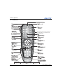
3.1 Using the IR Remote....................................................................................................................3-1
3.1.1 IR Remote ............................................................................................................................3-2
3.1.2 Wired Remote ......................................................................................................................3-3
3.1.3 IR Remote Commands .........................................................................................................3-3
Power ON/OFF .....................................................................................................................3-3
Test ........................................................................................................................................3-3
Auto .....................................................................................................................................3-3
Channel .................................................................................................................................3-4
Slot 1, 2, 3, and 4 ..................................................................................................................3-4
Input ......................................................................................................................................3-4
PIP .........................................................................................................................................3-4
Swap ......................................................................................................................................3-4
Contrast .................................................................................................................................3-4
Bright ....................................................................................................................................3-4
Gamma ..................................................................................................................................3-4
Number Keys ........................................................................................................................3-5
Help .......................................................................................................................................3-5
Menu .....................................................................................................................................3-5
OSD (On-screen display) ......................................................................................................3-5
Shutter ...................................................................................................................................3-5
Function Key .........................................................................................................................3-5
Proj ........................................................................................................................................3-6
Enter ......................................................................................................................................3-6
Exit ........................................................................................................................................3-6
Arrow Keys ..........................................................................................................................3-6
Laser ......................................................................................................................................3-6
3.2 Navigating the Menus ..................................................................................................................3-7
3.2.1 Main Menu ...........................................................................................................................3-7
3.2.2 On-line Help.........................................................................................................................3-7
3.2.3 The Global Icon ...................................................................................................................3-8
3.2.4 Using Slidebars and Other Controls.....................................................................................3-8
ii
Matrix StIM/SIM User Manual
020-100306-05 Rev. 1 (03-2012)
Table of Contents
3.2.5 Editing Text .........................................................................................................................3-9
3.3 Using Inputs and Channels ..........................................................................................................3-10
3.3.1 Inputs ...................................................................................................................................3-10
Switching Inputs ..................................................................................................................3-10
3.3.2 Channels ..............................................................................................................................3-11
Creating a New Channel .......................................................................................................3-12
Using A Channel ..................................................................................................................3-12
Channel Setup Menu ............................................................................................................3-13
Signal Type ...........................................................................................................................3-13
Copy a Channel ....................................................................................................................3-14
Delete a Channel ...................................................................................................................3-14
Delete Multiple Channels ....................................................................................................3-15
Editing a Channel .................................................................................................................3-15
3.4 Adjusting the Image.....................................................................................................................3-16
3.4.1 Automatic Image Setup .......................................................................................................3-16
3.4.2 Main Menu > Size and Position Menu ................................................................................3-17
Resize Presets .................................................................................................................................3-17
Size .......................................................................................................................................3-18
Vertical Stretch .....................................................................................................................3-18
Pixel Track ............................................................................................................................3-19
Pixel Phase ............................................................................................................................3-19
H-Position .............................................................................................................................3-19
V-Position .............................................................................................................................3-19
Keep Aspect on Auto Setup ..................................................................................................3-19
Blanking ................................................................................................................................3-19
3.4.3 Image Settings Menu ...........................................................................................................3-20
Image Settings > Input Levels Menu ....................................................................................3-24
Image Settings > Advanced Image Settings Menu ...............................................................3-26
3.4.4 Main Menu > Channel Setup ...............................................................................................3-30
3.4.5 Main Menu > Configuration ................................................................................................3-30
Language ..............................................................................................................................3-30
Output Options ....................................................................................................................3-31
Power Management ..............................................................................................................3-32
Date & Time .........................................................................................................................3-32
Menu Preferences .................................................................................................................3-33
Communications ...................................................................................................................3-34
Geometry & Color ................................................................................................................3-37
Brightness Uniformity ..........................................................................................................3-39
Diagnostics & Calibration ....................................................................................................3-46
Service ..................................................................................................................................3-48
Option Card Settings ............................................................................................................3-48
ArrayLOC Menu ...................................................................................................................3-48
Managing Colors with ArrayLOC ........................................................................................3-57
Managing InfraRGB with IRLOC ........................................................................................3-65
3.4.6 Main Menu > Status.............................................................................................................3-69
3.4.7 Main Menu > Secondary Input & Switching.......................................................................3-69
Matrix StIM/SIM User Manual
020-100306-05 Rev. 1 (03-2012)
iii
Table of Contents
3.4.8 Main Menu > Language......................................................................................................3-72
3.4.9 Main Menu > Test Pattern ...................................................................................................3-72
3.4.10 How Color Settings Interact in a StIM Array ....................................................................3-72
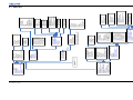
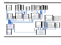
4: Menu Tree
4.1 Menu Tree....................................................................................................................................4-3
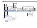
4.1.1 Menu Tree Continued - Configuration.................................................................................4-4
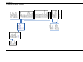
4.1.2 Menu Tree Continued - Geometry and Color ......................................................................4-5
4.1.3 Menu Tree Continued - ArrayLOC......................................................................................4-6
5: Maintenance
5.1 Safety Warnings and Guidelines..................................................................................................5-1
5.2 Maintaining Proper Cooling ........................................................................................................5-1
5.3 Maintenance and Cleaning...........................................................................................................5-1
5.3.1 Warnings and Safety Guidelines..........................................................................................5-1
5.3.2 Labels and Markings ............................................................................................................5-2
5.3.3 Instructions...........................................................................................................................5-2
5.3.4 Projector Location................................................................................................................5-2
5.3.5 Servicing ..............................................................................................................................5-2
5.3.6 Cleaning and Maintenance Guide ........................................................................................5-3
5.4 Light Module Replacement .........................................................................................................5-3
5.5 Lens Replacement........................................................................................................................5-3
6: Troubleshooting
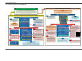
6.1 Troubleshooting Guidelines.........................................................................................................6-1
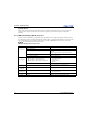
6.2 System Warnings / Errors ............................................................................................................6-1
System Warnings ..................................................................................................................6-1
System Errors ........................................................................................................................6-2
6.2.1 LED Status Display On the Projector ..................................................................................6-2
6.2.2 Error Codes ..........................................................................................................................6-3
6.3 Power ...........................................................................................................................................6-4
6.3.1 Projector Does Not Power ON.............................................................................................6-4
6.4 Light Module ...............................................................................................................................6-5
6.4.1 Light Module Suddenly Goes OFF ......................................................................................6-5
6.5 Displays .......................................................................................................................................6-5
6.5.1 The Projector is ON, but There is No Display .....................................................................6-5
6.5.2 The Display is Jittery or Unstable........................................................................................6-5
6.5.3 The Display is Faint .............................................................................................................6-5
6.5.4 The Upper Portion of the Display is Waving, Tearing or Jittering......................................6-5
6.5.5 Portions of the Display are Cut OFF or Warped to the Opposite edge................................6-6
6.5.6 Display Appears Compressed (Vertically Stretched) ..........................................................6-6
6.5.7 Data is Cropped from Edges ................................................................................................6-6
6.5.8 Display Quality Appears to Drift from Good to Bad, Bad to Good ....................................6-6
6.5.9 Display has Suddenly Froze.................................................................................................6-6
6.5.10 Colors in the Display are Inaccurate .................................................................................6-6
iv
Matrix StIM/SIM User Manual
020-100306-05 Rev. 1 (03-2012)
Table of Contents
6.5.11 Display is Not Rectangular ...............................................................................................6-6
6.5.12 Display Is “Noisy” ............................................................................................................6-6
6.6 ArrayLOC ....................................................................................................................................6-7
6.6.1 Cannot Find Color Adjustment Controls .............................................................................6-7
6.6.2 Color/Image Settings Are Greyed Out.................................................................................6-7
6.6.3 Sensor Isn’t Calibrated (yellow alert)..................................................................................6-7
6.6.4 Invalid Target Gamut (yellow alert) ....................................................................................6-7
6.6.5 Unable to Achieve Target Brightness/Gamut (yellow alert) ...............................................6-7
6.6.6 Troubleshooting Tree - Color And Brightness Array..........................................................6-9
6.6.7 Troubleshooting Tree - Array Brightness............................................................................6-10
6.6.8 Troubleshooting Tree - Array Colors ..................................................................................6-11
6.6.9 Bright/ColorLOC Setup and Walkthrough ..........................................................................6-12
6.6.10 Array Status Decoder & Setting the RGB Brightness Target Unit....................................6-13
7: Specifications
7.1 Regulatory ...................................................................................................................................7-1
7.1.1 Safety ...................................................................................................................................7-1
7.1.2 Environmental Regulations..................................................................................................7-1
7.1.3 Emissions .............................................................................................................................7-1
7.1.4 Electromagnetic Compatibility ............................................................................................7-2
7.1.5 Immunity..............................................................................................................................7-2
7.2 Matrix StIM/SIM Specifications .................................................................................................7-2
7.2.1 Display .................................................................................................................................7-2
7.3 Lenses
....................................................................................................................................7-3
7.4 Power Requirements ...................................................................................................................7-4
7.5 Light Module ..........................................................................................................................................7-4
7.6 Physical Specifications ................................................................................................................7-4
Maximum Product Dimensions (L x W x H) .......................................................................7-4
Product Weight .....................................................................................................................7-4
7.6.1 Projector Dimensions and Mounting Information ...............................................................7-5
7.7 Environment ................................................................................................................................7-6
Operating Environment ........................................................................................................7-6
Non-Operating Environment ................................................................................................7-6
7.8 Standard and Optional Components ............................................................................................7-7
7.8.1 Standard Components ..........................................................................................................7-7
7.8.2 Optional Accessories ...........................................................................................................7-7
User Kit (P/N: 125-107109-xx) ............................................................................................7-7
Input Cards Other Input Cards ..............................................................................................7-7
Service Manual .....................................................................................................................7-7
Motoblend Mounting Kit ......................................................................................................7-7
Lenses ...................................................................................................................................7-7
7.9 Inputs ..........................................................................................................................................7-8
Matrix StIM/SIM User Manual
020-100306-05 Rev. 1 (03-2012)
v
Table of Contents
A: Interconnect Drawing
A.1 Interconnect Drawing..................................................................................................................A-1
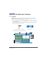
B: Web User Interface
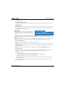
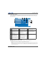
B.1 Logging On .................................................................................................................................B-1
B.2 Navigating the Web User Interface.............................................................................................B-2
B.2.1 Help Text .............................................................................................................................B-2
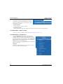
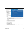
B.3 Basic Operation ...........................................................................................................................B-3
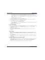
B.3.1 Main Tab - General .............................................................................................................B-3
B.3.2 Main Tab - Status ................................................................................................................B-3
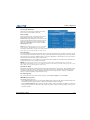
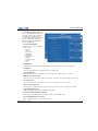
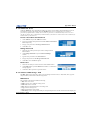
B.3.3 Tools Tab - Virtual OSD ....................................................................................................B-4
Virtual OSD Menu ................................................................................................................B-5
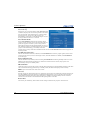
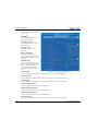
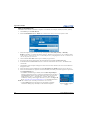
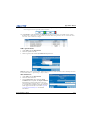
B.3.4 Admin Tab - System............................................................................................................B-7
Upload a Logo File or Gamma File ......................................................................................B-7
Create a Backup File .............................................................................................................B-8
Restore a File ........................................................................................................................B-8
Perform a Diagnostic Test using Interrogator .......................................................................B-8
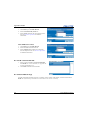
B.3.5 Admin Tab - Users .............................................................................................................B-9
Create a User Name and Password .......................................................................................B-9
Change Password ..................................................................................................................B-9
Delete User ...........................................................................................................................B-9
B.3.6 Advanced Tabbed Page - RTE ............................................................................................B-9
RTE Buttons .........................................................................................................................B-9
B.3.7 Add a Serial Command .......................................................................................................B-12
B.3.8 About Tabbed Page .............................................................................................................B-12
C: Serial Communication
C.1 Connection and Use ....................................................................................................................C-1
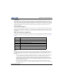
C.2 Understanding Message Format..................................................................................................C-1
C.2.1 Basic Message Structure .....................................................................................................C-2
Start and End of Message .....................................................................................................C-2
Prefix Characters (Optional) .................................................................................................C-2
Projector Numbers (Optional) ..............................................................................................C-2
Function Code .......................................................................................................................C-2
+Subcode ..............................................................................................................................C-3
Request/Reply Symbols ........................................................................................................C-3
Other Special Functions (Optional) ......................................................................................C-3
Data .......................................................................................................................................C-3
Text Parameters ....................................................................................................................C-4
C.2.2 Sample Messages and their Meaning ..................................................................................C-4
C.2.3 What is Actually Sent in a Message ....................................................................................C-5
C.2.4 Maximizing Message Integrity............................................................................................C-5
C.2.5 Accessing Specific Channels or Inputs ...............................................................................C-6
C.2.6 Flow Control........................................................................................................................C-6
C.2.7 Network Operation ..............................................................................................................C-7
vi
Matrix StIM/SIM User Manual
020-100306-05 Rev. 1 (03-2012)
Table of Contents
C.3 Description Of Control Types.....................................................................................................C-8
C.3.1 Subclasses ...........................................................................................................................C-8
C.3.2 Control Groups....................................................................................................................C-8
C.3.3 Access Levels......................................................................................................................C-8
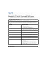
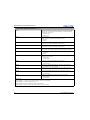
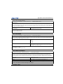
D: Serial Command Reference
Matrix StIM/SIM User Manual
020-100306-05 Rev. 1 (03-2012)
vii
1 Introduction
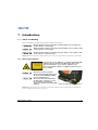
1.1
Labels and Marking
Observe and follow all warnings and instructions marked on the projector.
Danger symbols indicate a hazardous situation which, if not avoided, will
result in death or serious injury.
Warning symbols indicate a hazardous situation which, if not avoided, could
result in death or serious injury.
Caution symbols indicate a hazardous situation which, if not avoided, could
result in minor or moderate injury.
NOTICE: Information
1.2
provided with this heading alerts users to key information not related to personal injury.
General Precautions
The projector is a class 2M source of visible and invisible LED
radiation. Directly Viewing the LED output with certain
optical instruments (e.g. eye loupes, magnifiers and
microscopes) within a distance of 100 mm (3.94”) may pose
an eye hazard.
Disconnect the AC cord before
disconnecting the light module from
the Projector Head Module (PHM).
Power should always be
disconnected from the illumination
module before servicing, to avoid
the possibility of inadvertent
exposure to visible and invisible LED
radiation.
Figure 1-1 LED Caution Label Location
This projector must be operated in an environment that meets the operating range specification, as
listed in Operating Environment, on page 7-6.
NOTICE:
Matrix StIM/SIM User Manual
020-100306-05 Rev. 1 (03-2012)
1-1
Section 1: Introduction
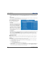
1.3
Purchase Record and Service Contacts
Whether the projector is under warranty or the warranty has expired, Christie’s highly trained and extensive
factory and dealer service network is always available to quickly diagnose and correct projector malfunctions.
Complete service manuals and updates are available for all projectors. If a problem is encountered with any
part of the projector, contact your dealer. Usually servicing is performed on site. If you have purchased the
projector, fill out the information below and keep with your records.
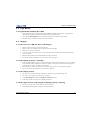
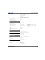
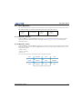
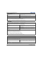
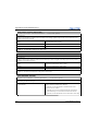
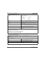
Table 1.1 Purchase Record
Dealer:
Dealer or Christie Sales/Service Contact Phone Number:
Projector Serial Number*:
Purchase Date:
Installation Date:
* The serial number can be found on the license label located on the back of the projector.
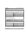
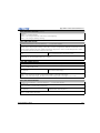
Table 1.2 Ethernet Settings
Default Gateway
DNS Server
Projector IP Address
Subnet Mask
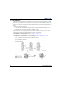
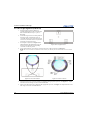
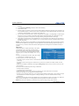
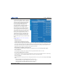
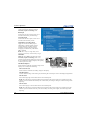
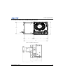
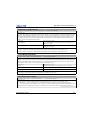
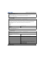
1.4
Projector Overview
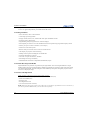
The Matrix StIM and Matrix
SIM are professional quality
WUXGA data projectors
featuring the latest in DLP
display technology to achieve
high brightness, high resolution
video projection images. These
projectors use Christie’s
exclusive KoRE electronics
and firmware to accept data,
graphics and video input signals
for projection onto front or rear
projection screens.The modular
design of the Matrix StIM/SIM projectors makes them an ideal choice for the demanding needs of simulation
applications as well as 24/7 command and control centers, telecommunications, surveillance and broadcasting
applications.
NOTE:
1-2
The rubber mount has been removed from around the lens mount for illustration purposes.
Matrix StIM/SIM User Manual
020-100306-05 Rev. 1 (03-2012)
Section 1: Introduction
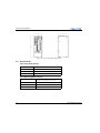
1.4.1 Projection Head Module (PHM)
The PHM is the center module of the projector. It contains the projection lens, IR sensor, DMD, light module
and other optical components. It also supplies the electrical interfaces required to drive these components.The
projector Light Module (LM) consists of four LEDs and combining optics.
Main Power Switch
Power should always be disconnected from the illumination module before
servicing, to avoid the possibility of inadvertent exposure to visible and invisible LED
radiation. Directly viewing the illumination module optical output through certain optical
instruments (for example, eye loupes, magnifiers and microscopes) within a distance of 100
mm (3.94”) may pose an eye hazard.
The Main Power Switch is located above the AC receptacle on the Light Module (LM). Place this switch in
the OFF position to cut all power to the projector before disconnecting from an AC wall outlet.
1.4.2 Electronic Module (EM)
The EM module contains the main electronics and input connectors of the projector.
Input Panel
All source connections are made to the main input panel. If additional connections are required, install one of
the available optional input modules. For more details on connecting sources, see 2.3 Connecting Sources, on
page 2-7.
Status Display
The two-digit status display window displays the current status of the projector. If there is an error during
operation, an error code number will display. During normal operation, ON will appear in the window.
Status LED
Located next to the two-digit status display is a single LED that illuminates one of three colors to convey the
current status of the system. A solid red LED shows a system error and the corresponding error code will
display in the status display. See 6.2 System Warnings / Errors, on page 6-1 for a description of LED
variations. Press Exit twice on the keypad to acknowledge and clear the error.
1.4.3 IR Sensor
The projector has a front IR sensor that is optimally placed to receive transmissions from the IR remote from
up to 100 feet away, regardless of the projector configuration. For uninterrupted communications with the
projector, it is important to keep the transmission path to this sensor unobstructed at all times and to point the
IR remote directly at the projector (or center of the screen in rear screen applications).
1.4.4 Image Processing
A Dual Image Processing Card (DIPC) provides an interleaved InfraRGB mode allowing simultaneous display
of 2 image sources (1 channel RGB, and the other channel IR). A 120Hz frame rate capability supports two
60Hz image sources; 1RGB source and 1IR source, or 2 RGB sources.
Matrix StIM/SIM User Manual
020-100306-05 Rev. 1 (03-2012)
1-3
Section 1: Introduction
Independent curve control for each path (RGB and IR) allows video transforms, such as gamma and power
curves to be applied independently to the RGB and the IR frames.
1.4.5 Key Features
• Native WUXGA, 1920 x 1200 resolution
• 10-bit image processing module
• Display of RGB, NTSC, PAL, and SECAM video inputs and HDTV formats
• Picture-in-Picture (PIP) display
• Edge Blending ability using software for seamless displays
• Dual frequency IR sensor for use with standard IR remote and optional long-range dual frequency remote
• Memory for up to 99 custom “channels” (source setups)
• Intuitive on-screen menu system
• Built-in GPIO port to enable active control of external devices
• LED display for projector status monitoring
• Multiple control options including RS-232 and RS-422
• On-board ChristieNET software
• Universal AC input 100-240 VAC, 50/60Hz
• Dual Image Processing Card (DIPC)
• InfraRGB mode interleaves 2 independent (RGB and IR) inputs
1.4.6 How the Projector Works
Sequential RGB color primaries are generated by the light module. This colored light illuminates a single
DMD located in the projector head module. In addition to the RGB color primaries, an IR LED can be turned
on to illuminate the DMD. The reflected light from the DMD chip then passes through the projection lens to
the screen to display the image.
1.4.7 List of Components
Make sure these components were received with the projector:
• Projector Head Module (PHM), with attached Illumination Module (LM)
• Electronics Module (EM)
• Warranty Card
• Web Registration Form
• Line Cord (rated, North American)
Each projection system requires a User Kit (P/N: 125-107109-xx). If you did not receive a User Kit or if
you want to purchase additional kits, you can order them separately.
NOTE:
1-4
Matrix StIM/SIM User Manual
020-100306-05 Rev. 1 (03-2012)
2 Installation and Setup
This section explains how to install, connect, and optimize the projector display.
2.1
Pre-Installation Considerations
When designing a projection room for either a permanent or temporary installation, consider positioning the
projector and screen for maximum audience coverage and space efficiency. For example, placing the screen
along the larger wall in a rectangular room reduces audience coverage.
2.1.1 Installation Considerations
• Operating single or multiple units.
• Room size.
• Lighting and audience seating.
• Distance between the audience and the display.
• Angle from which the display is viewed.
• Ambient temperature must stay below 40°C (95°F). Changes in temperature can cause drifts in the projector
circuitry, which may affect performance. Keep the projector away from heating and air conditioning vents.
• Keep the projector away from all devices radiating electromagnetic energy. For example, motors and
transformers, slide projectors, speakers, power amplifiers and elevators.
• Use an optical mirror for rear screen installations to shorten the optical light path and use less space in the
projection room.
2.1.2 Ventilation
NOTICE: Do
not obstruct the air exchange to the projector.
The projector vents provide ventilation, both for intake and exhaust. Do not block or cover these openings. Do
not install the projector near a radiator or heat register, or within an enclosure. Make sure there is a minimum
clearance of 25cm (10”) on the left, right, top and rear sides of the projector.
Matrix StIM/SIM User Manual
020-100306-05 Rev. 1 (03-2012)
2-1
Section 2: Installation and Setup
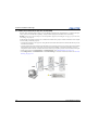
2.1.3 Lifting, Transporting and Mounting
Mount the projector to a sturdy, flat surface that fits the entire projector.
Use all four mounting points to secure the projector to the surface.
Maintain a minimum clearance of 25cm (10”) around the projector, called a
“stay out zone”, for air circulation and clearance for cable connections to the
input panel. Insufficient stay out zone clearance can cause the projector to
overheat during operation and/or place undue stress on source connections.
The projector should be lifted by 2 people. Use a stable cart to transport the projector. Refer to the drawings
given for your specific projector model for the mounting hole location and other technical information and
restrictions which may be useful during installation.
Figure 2-1 Mounting Holes
2-2
Matrix StIM/SIM User Manual
020-100306-05 Rev. 1 (03-2012)
Section 2: Installation and Setup
2.2
Installing the Projector
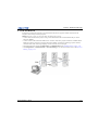
2.2.1 Unpacking the Projector
The projector is shipped assembled with the projection lens shipped separately. The
lens must be installed prior to setting up the projector.
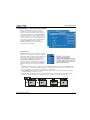
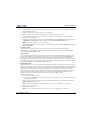
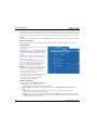
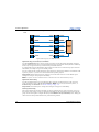
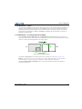
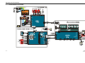
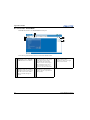
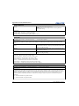
Interconnection Diagram
Electronics Module
1. Remove the projector from the box and packing material.
EM Power
Link A Link B
NOTE: Save packing material for at least one projector in case a projector needs
EM Network
to be shipped for service.
Projection Head Module
2. Connect the Electronics Module to the Projector Head Module and Light
Module.
Link B
Link A
EM Network
Light Module
EM Power
Shown in lens-vertical configuration (top view)
Same connections for lens-horizontal configuration
Figure 2-2 Module
Interconnections
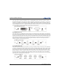
2.2.2 Installing the Lens
1. Remove the rear lens cap from the lens. Keep the front lens cap on the lens.
2. Rotate the lens clamp to the OPEN position (Figure 2-3).
Figure 2-3 Rotate to Open
Figure 2-4 Security Screws
3. Remove and retain the (2) security screws from the lens mount, see Figure 2-4.
4. Align the lens interface plate with the lens mount. Fully insert the assembly straight into the lens mount
opening without turning. NOTICE: Ensure the lens IS NOT inserted at an angle as this can cause damage.
5. Rotate the lens clamp to the CLOSED position before fastening the security screws.
6. Fasten the security screws (Figure 2-4). NOTICE: Security screws MUST be installed.
7. Remove the front lens cap.
For more information concerning lenses, see 2.11 Projection Lenses, Lens Mount and Other Features, on page
2-19 and 2.12 Cleaning the Lens, on page 2-19.
Matrix StIM/SIM User Manual
020-100306-05 Rev. 1 (03-2012)
2-3
Section 2: Installation and Setup
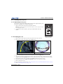
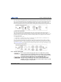
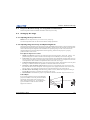
2.2.3 Lens Focus Adjustment for Fixed Lenses
This section describes best practices for lens focus adjustment of the 0.64:1 WUXGA lens (PN:
002-120444-02) and the 0.75:1 (PN: 002-120415-01). The lenses have focus and field curvature correction to
sharpen the projected image. Failure to properly adjust lens focus results in an image that is not uniformly
focused and contains geometric distortion.
1. Loosen the main locking screw and the focusing screw.
2. Adjust the focusing screw for best focus in the image center.
3. Loosen the field curvature locking screw and adjust the field curvature focusing ring to sharpen the image
corners. Refer to the image below as an aid to gage the specific preset for your screen size.
4. Finally the focus screw should be adjusted for best overall screen focus.
5. Although it is not necessary, you may want to retighten the main locking screw. NOTE: Use a maximum of
4in.-lbs to tighten the main locking screw.
2-4
Matrix StIM/SIM User Manual
020-100306-05 Rev. 1 (03-2012)
Section 2: Installation and Setup
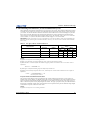
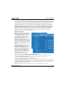
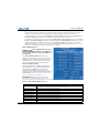
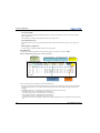
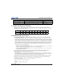
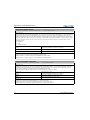
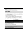
2.2.4 Calculating Throw Distance, Position and Mount Projector
Throw distance is the distance measured from your projector to the screen. This calculation determines if there
is enough room to install your projector with a desired screen size and if the image will be of the right size for
your screen. To estimate the throw distance take the horizontal width of the screen and multiply it by the lens
throw ratio. The result determines approximately the distance the projector should be positioned from the
screen to project a focused image large enough to fill the screen. For example, using a 1.2:1-1.6:1 zoom lens
set at its widest (1.2:1) throw ratio, throw distance would roughly be 1.2 x screen width.
Use the lens and screen size to calculate the precise throw distance. Due to lens manufacturing
tolerances for lens focal length, actual throw distance can vary ±2% between lenses with the same nominal
throw ratio.
IMPORTANT:
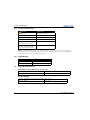
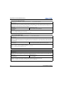
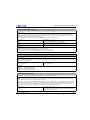
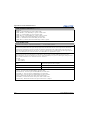
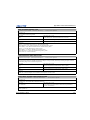
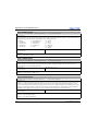
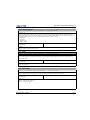
Table 2.1 Lens Types, Offsets and Throw Distances
CHRISTIE Lens
Throw Distance
Offset Percentage (Offset Pixels)
Horizontal
Specified Throw Distance
Range
Vertical
Inches
Meters
Min
Max
Min
Max
0.64:1
11% (211)
26% (312 px)
40
120
1.0
3.1
1.2-1.6
75% (1440)
138% (1656px)
59
213
1.5
5.4
0.75:1
80% (1536)
134% (1608 px)
28
102
0.7
2.6
NOTES:
1) Offsets
2) Image
are subject to ±7% centering tolerance.
size outside the specified width range may result in reduced image quality.
3) Throw
distance is measured from the marked exit pupil position on the lens to the screen. Throw ratio is
defined as:
throw distance
Throw Ratio = ----------------------------------- 2%
screen width
4) 100%
offset is defined as having all pixels shifted beyond the axis.
5) Offsets
are measured from optical lens centre, which may not coincide with mechanical centre% offset is
defined as:
# of pixels of offset
% Offset = -------------------------------------------------------------------- 100
half vertical panel resolution
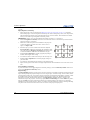
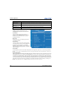
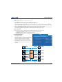
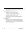
Projector Vertical and Horizontal Position
The projection lens and the screen type determine the vertical and horizontal position of your projector in
relation to the screen. Ideally, you should position the projector perpendicular to the screen to make the image
appear rectangular instead of keystoned (trapezoidal). You can offset vertical position of the image (move it
above or below the optical axis) by adjusting the lens mount. The type of projection lens you install determines
the amount of available vertical offset. Vertical offset can be expressed as the percent of half the image height
or the number of pixels of shift from lens center.
NOTES:
1) Offsets
are subject to ±7% centering tolerance.
Matrix StIM/SIM User Manual
020-100306-05 Rev. 1 (03-2012)
2-5
Section 2: Installation and Setup
2)%
# of pixels of offset
offset is defined as: % Offset = ------------------------------------------------------------------- 100
half vertical panel resolution
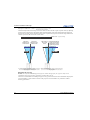
The horizontal position of the image can also be offset (moved to the left or right of optical center) by adjusting
the lens mount. The amount of horizontal offset available depends on the lens installed and if the image has
already been vertically offset. Horizontal offset can be expressed as the percent of half the image width or the
number of pixels of shift to one side of lens center.
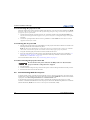
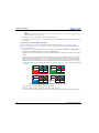
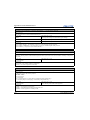
Example of Horizontal Offset (WUXGA pixels represented)
960 pixels
display to left
of lens center
960 pixels
display to right
of lens center
Shaded area = projected image
480 pixels to 1440 pixels displayed
left of lens to right of lens center
center
or 480 pixels of shift
to right of lens center
#1 In this example, no offset is applied; therefore, #2 In this example, 50% offset is applied; therefore,
half of the image appears to the left or lens center
3/4 or 75% of the image appears to the one side of
and half appears to the right.
the lens center.
Mounting the Projector
NOTICE: Use only the CHRISTIE approved projector mounts designed for your projector. Refer to the
installation instructions and safety guidelines provided with in the kit.
There are several methods for mounting the projector. In typical front and rear screen installations the projector
can be mounted to a secure and level surface. The projector can be mounted in any orientation without
affecting performance.
2-6
Matrix StIM/SIM User Manual
020-100306-05 Rev. 1 (03-2012)
Section 2: Installation and Setup
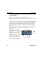
2.3
Connecting Sources
All source connections are made to the input panel of the Electronics Module. Each input is labeled for easy
identification. Using the correct cable(s), connect your source. An interconnection label is available for
reference on the light module. Sources are connected to the Input Panel located at the top of the EM. The Input
Panel has slots for one image processor board and up to four input cards. The input cards are hot swappable;
they can be plugged in and out while the projector is running. The image processor should only be replaced
when the projector is OFF or when it is in STANDBY mode.
The video card that is installed in your projector determines the type of video source you can use. These video
cards are supported:
• High-Definition Multimedia Interface/Twin HDMI (High-Definition Multimedia Interface)
• Analog BNC
• Dual SD/HD-SDI (Serial Digital Interface)
• Dual Link DVI
• Video Decoder
These cards slide into any of the available option slots. One or more of the option slots may be used with any
combination of option cards, including multiples of the same card type. Up to 2 active inputs can be displayed
at any time, either from one card or from 2 cards. These 2 inputs can be routed to outputs or to the main or
secondary video image. NOTE: Use only high-quality shielded cables for all connections.
LEDS
LEDs are located on the faceplate of each input card and indicate the following:
• Power ON - Green
• Signal Valid - Green
• Signal Invalid - OFF
DVI Digital Video
Use the DVI-I connector to connect either analog or digital video devices to the projector. Use a cable with
DVI-I connectors at both ends to connect devices that transmit digital and analog video signals. NOTE: For
true digital output from devices that transmit digital signals, connect to the DVI-I connector.
Matrix StIM/SIM User Manual
020-100306-05 Rev. 1 (03-2012)
2-7
Section 2: Installation and Setup
Dual Link Digital Video Input (DVI) Input Card
This card accepts a maximum 330MHz DVI-D or 165MHz HDMI signal via the DVI-I connector without
High-Bandwidth Digital Content Protection (HDCP) and analog video signals over the DVI-I or 15-pin VGA
connector. The module can simultaneously support a digital signal on the DVI input and an analog signal on
the VGA port, however it does not support 2 analog signals at the same time. There are 4 LEDs on the module
faceplate. PWR indicates power is applied and the card is initialized, and the other 3 LEDs on the right-side of
the corresponding connectors indicate that a valid signal has been detected.
Twin HDMI Input Card
This card accepts 1 or 2 HDMI inputs, and can route one or both inputs to the card’s outputs. Any input from
any card can be looped out of this card. The output label ‘1-OUT’ loops out the main image being displayed on
the projector. The output labelled ‘2-OUT’ loops out the image displayed in the picture in picture (). Any input
from any optional input card can be looped out of this card. There are five LEDs on the module faceplate. The
PWR on the left side indicates power is applied, and that the card is initialized. The LEDs to the right side of
the corresponding connectors indicate that a valid signal is detected. In the case of the outputs, the LED
indicates a signal is currently being looped out.
Analog BNC Input Card
This card accepts several types of sync modes. In 5-wire sync mode all 5 BNC connectors are used. If H and V
connectors are swapped, this card will still operate normally. An analog graphic source such as a VGA from a
PC can be connected. The card can operate in 4-wire sync mode, which accommodates 4-wire RGBC sources.
The composite sync cable can be connected to either the H/C BNC or the V BNC. The card supports 3-wire
RGB or YPBPr sync modes, sometimes called sync-on-Green (SOG). In this mode the H/C and V connectors
are not used. The sync is connected to the Green/Y BNC connector. This card offers no loop out capability.
There are 2 LED’s on the module faceplate. PWR indicates power has been applied and the card is initialized,
signal indicates a valid signal has been detected.
2-8
Matrix StIM/SIM User Manual
020-100306-05 Rev. 1 (03-2012)
Section 2: Installation and Setup
Dual SD/HD-SDI Input Card
This card accepts both standard-definition (SD) and high-definition (HD) serial-digital-interface (SDI) signals
from 1 of 2 standard-definition (SD) or high-definition (HD) SDI sources. Both single-link HD and dual-link
HD signals are accepted. The card has two SD/HD-SDI outputs, each of which is “loop through” for its
respective input. There are three LEDs on the module faceplate. PWR indicates power has been applied and
the card is initialized, and the two signal LEDs indicate a valid signal has been detected on the respective input.
Video Decoder Input Card
This card accepts and decodes standard definition (SD) video. This includes CVBS (composite video), SVideo, and component sources. This card supports as many as 6 video signals, four of them on BNC
connectors and 2 on four-pin mini-DIN connectors. Each mini-DIN connector accepts one S-Video signal. The
first BNC accepts composite video (only), while the remaining 3 BNCs can be grouped to allow one of the
following combinations:
• 3 CVBS sources on 4, 5 & 6
• 1 CVBS source, 1 S-Video source: Luma (Y) connected to 4 (Sy) and Chroma (C) connected to 6 (Sc)
• 1 YPbPr source: component signal on 4(Pr), 5(Y) & 6(Pb)
The video decoder input card has 8 LED indicators. The PWR LED indicates that the module is installed
properly, and has been successfully configured. The YPbPr LED indicates that a valid component signal has
been detected on inputs 4, 5, and 6 (Component input grouping must also be selected in the projector’s menu see Section 3 Operation. The remaining LEDs are each associated with one of the inputs and indicate a valid
signal has been detected on that input.
2.4
Power Connection
Do not operate if the AC supply and cord are not within the specified
voltage and power range. The North American rated line cord is supplied
with this projector. For all other regions, use only a regionally approved line
cord, power plug and socket. Do not use a damaged line cord.
The projector is a class 2M source of visible and invisible LED radiation.
Directly viewing the LED output with certain optical instruments (for
example, eye loupes, magnifiers and microscopes) within a distance of 100
mm (3.94”) may pose an eye hazard.
Matrix StIM/SIM User Manual
020-100306-05 Rev. 1 (03-2012)
2-9
Section 2: Installation and Setup
2.4.1 Connecting the projector to AC
The input voltage to the projector must be capable of 100-240 VAC. Use only a correctly rated line cord. NOTE:
Do not use a line cord or AC supply not in the specified voltage and power range. See Section 7 Specifications
for projector power requirements.
1. Connect an approved line cord to the projector AC receptacle, located on the Light Module. NOTE: Use
only the line cord supplied with the projector or a power cord of correct ratings that comply with regional
standards.
2. Connect the 3-pronged end of the line cord to a grounded AC outlet. NOTE: The outlet must be near the
equipment and easily accessible.
2.4.2 Turning the Projector ON
1. Flip the power switch on the LM (Light Module) ON. The projector takes about 2 minutes to initialize. The
status light beside the LED window turns yellow.
NOTE: The Electronics Module has a circuit breaker which is generally left ON. Certain error conditions
can turn the circuit breaker off. The circuit breaker must be ON for proper projector function.
2. Using the remote keypad, press the Power button, and then the UP arrow.
3. Press one of the input keys on the remote to select and display the image for the source connected in 2.3
Connecting Sources, on page 2-7. For more information on the keys available on the remote and their
function, see 3.1.1 IR Remote, on page 3-2.
For more information about sources, see 2.3 Connecting Sources, on page 2-7.
2.4.3 Disconnecting the projector from AC
Do not turn the main power switch to the OFF position or disconnect the
projector until the cooling fans have stopped.
1. Stop the projector.
2. After the internal cooling fans stop, move the main power switch on the light module to the OFF position.
3. Disconnect the line cord from the wall outlet.
2.5
Communicating With the Projector
To use the remote control, point the remote at the display screen or the projector IR sensor. To use the remote
with the cable, connect the cable to the remote and to the connector labeled REMOTE on the Electronics Module
input panel. Check Wired Keypad Enabled in the Communications menu.
As an alternative to the projector keypad or remote, communicate with the projector using a PC or other
controller. Commands and feedback are sent to the projector's Electronics Module using Ethernet or serial links
(RS232 and RS422). NOTE: Do not connect to the Projector Head Module (PHM).
2-10
Matrix StIM/SIM User Manual
020-100306-05 Rev. 1 (03-2012)
Section 2: Installation and Setup
2.6
Projector Network Setup for External Communication
IMPORTANT: To complete the projector network setup you will also need to connect the projectors together for
arrayLOC communication and functions. See ArrayLOC Network, on page 3-55.
This section outlines a several ways to set up a Matrix StIM/SIM projector network for external
communication.
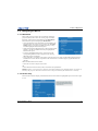
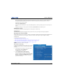
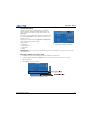
2.6.1 Ethernet (Recommended)
In the Ethernet network the controller communicates with each projector separately.
To add a projector to an Ethernet network:
• Connect a standard CAT5 Ethernet cable between the controller (or Ethernet hub) and the Ethernet port on
the projector Electronic Module.
• Set the IP address in Configuration > Communications > Ethernet Settings. See Ethernet Settings, on
page 3-36.
• Set Configuration > Communications > Network Routing to Separate. See Network Routing, on page 335.
Matrix StIM/SIM User Manual
020-100306-05 Rev. 1 (03-2012)
2-11
Section 2: Installation and Setup
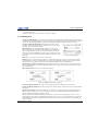
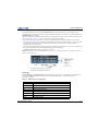
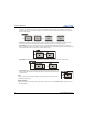
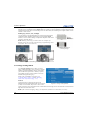
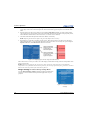
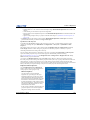
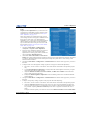
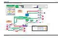
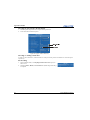
2.6.2 Mixed Network
In the mixed network the controller can communicate with the first projector and the command can be relayed
to each serially connected projector. This configuration is useful if you are using a non-RS232 controller with
the RS232 linking available between these projectors. The example shows both an RS422-compatible
controller and an Ethernet-connected PC for working with a network of projectors linked using their RS232 in/
out ports.
• Connect the controller to one projector:
• A standard CAT5 Ethernet cable between the controller (or Ethernet hub) and the Ethernet port on the
Electronic Module
• An RS-422 serial cable between the PC and the RS422 IN (pictured).
• Connect a serial cable between the RS232 OUT connector of the first projector Electronics Module and the
RS232 IN connector of the next projector Electronics Module. Connect the remaining projectors. RS232
communication cables must be good quality and no more than 25 feet in length.
• If you connected the controller, using an Ethernet cable, set the IP address in Configuration >
Communications > Ethernet Settings. See Ethernet Settings, on page 3-36.
• Set the serial options in Configuration > Communications. See Communications, on page 3-34.
• Set Configuration > Communications > Network Routing (see Network Routing, on page 3-35):
• To relay commands to all projectors set Network Routing to All Join.
• To isolate just RS422 communications, select RS232 and Ethernet Joined. Only projector #3 will
respond to the RS422 controller.
• To isolate just Ethernet communications, select RS232 and RS422 Joined—only projector #1 will
respond using Ethernet.
2-12
Matrix StIM/SIM User Manual
020-100306-05 Rev. 1 (03-2012)
Section 2: Installation and Setup
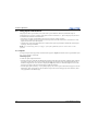
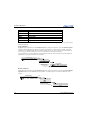
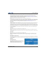
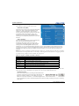
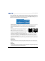
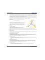
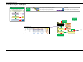
2.6.3 RS-232 Network
In the RS-232 network the controller can communicate with the first projector and the command can be
relayed to each serially connected projector.
NOTICE: Using
the wrong type of serial cable can damage the projector.
• Connect the controller to one projector using serial cable between the PC and the RS232 IN port on the
Electronic Module.
• Connect a serial cable between the RS232 OUT connector of the first projector Electronics Module and the
RS232 IN connector of the next projector Electronics Module. Connect the remaining projectors. RS232
communication cables must be good quality and no more than 25 feet in length.
• Set the RS-232 serial options in Configuration > Communications. See Communications, on page 3-34.
• Set Configuration > Communications > Network Routing to one RS232 and RS422 Joined. See Network
Routing, on page 3-35.
Matrix StIM/SIM User Manual
020-100306-05 Rev. 1 (03-2012)
2-13
Section 2: Installation and Setup
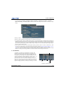
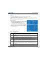
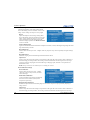
2.6.4 Mixed Serial Network (RS-232 and RS-422)
RS-422 serial communication is better over long distances than RS-232 communication. Use the RS-422 port
only if your device has RS-422 capability. Always read the equipment literature before connecting.
NOTICE: Connecting to the RS-422 port with incompatible equipment, including the wrong type of serial cable,
can damage the projector.
In the RS-422 network the controller can communicate with the first projector and the command can be relayed
to each serially connected projector.
• Connect the controller to one projector using RS-422 serial cable between the PC and the RS-422 IN port on
the Electronic Module.
• Connect an RS-232 serial cable between the RS232 OUT connector of the first projector Electronics Module
and the RS232 IN connector of the next projector Electronics Module. Connect the remaining projectors
using RS232 cables. RS232 communication cables must be good quality and no more than 25 feet in length.
• Set the serial options in Configuration > Communications. See Communications, on page 3-34.
• Set Configuration > Communications > Network Routing to one RS232 and RS422 Joined. See Network
Routing, on page 3-35.
2-14
Matrix StIM/SIM User Manual
020-100306-05 Rev. 1 (03-2012)
Section 2: Installation and Setup
2.7
Projector Network Setup for ArrayLOC Communication
See the Integration Guide for detailed information about arrayLOC setup.
2.8
Setting up the Image
2.8.1 Adjusting the Projection Lens
NOTICE: Lock
lens adjustments to prevent unnecessary tampering.
Loosen the adjustment locks on the lens barrel before making adjustments.
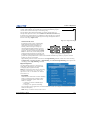
2.8.2 Adjusting Image Geometry and Optical Alignment
Only perform image alignment once the projector is fully assembled and powered up in its final location. Basic
image alignment ensures the image reflected from the DMD is parallel to and well-centered with the lens and
screen. This initial optical alignment is the foundation for optimizing images on the screen, and must be
completed before final boresight adjustments. Before beginning, ensure that the projector is properly
positioned relative to the screen.
Basic Optical Alignment Procedure
1. Display a test pattern: Appropriate for analyzing image focus and geometry, such as the “framing” test
pattern showing the cross-hair centered across the image. Press the Test key on the remote keypad.
2. Coarse focus: Do a quick preliminary focus and (if available) zoom adjustment with the primary lens. Do
not worry about consistency across the image at this point, just center focus. It is good practice to have the
zoom adjustment collar and the focus adjustment collar in the center of its range.
3. Center the image in the lens: Holding a piece of paper at the lens surface, adjust offsets as necessary until
the image is centered within the lens perimeter. A full white field works best for this.
4. If necessary, center the image on the screen: If the projector is mounted off-center to the screen axis,
then offset the lens as much as required. Aim the projector over slightly towards the center of the screen,
but use caution, as too much tilt will cause excessive keystone distortion. Lens offset will not.
5. Re-check side-to-side leveling: With the framing pattern on screen, double-check projector leveling so
the top edge of the image is parallel to the top edge of the screen.
6. Throw distance: Ensure that the projector is positioned in the throw distance range for the lens in use.
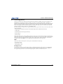
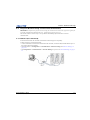
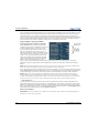
Folded Optics
In rear screen applications where space behind the
projector is limited, a mirror may be used to fold the
optical path. The position of the projector and
mirror must be accurately set – if considering this
type of installation contact Christie Customer
Support for assistance.
Matrix StIM/SIM User Manual
020-100306-05 Rev. 1 (03-2012)
2-15
Section 2: Installation and Setup
2.8.3 Boresight Alignment (Advanced)
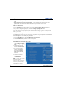
1. Display the Boresight Test Pattern by
pressing the Test key on the remote keypad,
then use the Left arrow key to cycle to
Boresight.
2. Focus the image on the cross-hair pattern at
the image center. Evaluate the focus on
cross-hair image I and II. If all three images
are in focus, no further action is required. If
boresight is required see step 3.
3. If boresight is required, see Figure 2-6 to
understand how the adjustment screws on
the lens mount affect the corresponding
cross-hairs on the test pattern.
Figure 2-5 Boresight Pattern
4. Use a 5mm Allen key to loosen the 3 locking setscrews on the lens mount, see Figure 2-7.
NOTE: The setscrews must be backed out several turns, so that they do not contact the inner lens mount
plate.
Figure 2-6 Cross-Hair Pattern
Figure 2-7 Screw Locations
5. Fine tune the focus of cross-hair pattern I by adjusting the appropriate capscrew, see Figure 2-7. Adjust
until the cross-hair image is in focus with minimal flare.
6. Adjust cross-hair pattern II, by adjusting the appropriate capscrew, see Figure 2-7. Adjust until the crosshair image is in focus with minimal flare.
2-16
Matrix StIM/SIM User Manual
020-100306-05 Rev. 1 (03-2012)
Section 2: Installation and Setup
7. Adjust cross-hair pattern III, by adjusting the
appropriate capscrew, see Figure 2-7. Adjust until the
cross-hair image is in focus with minimal flare.
8. Repeat steps 5, 6 and 7 as required until all three crosshair patterns are in equal sharp focus. If the boresight is
acceptable, see step 11. If the boresight does not appear
to be converging to an acceptable level of image quality
or if the lens will not focus over the correct range of
throw distances, then the boresight requires coarse
adjustment, see step 9.
9. The original factory boresight can be recovered
Figure 2-8 Position Setscrew Flush
approximately by positioning the three setscrews, see
Figure 2-7. Position the setscrews flush with the front
face of the lens mount plate and in contact with the inner lens mount plate, see Figure 2-7. This may
require adjusting both setscrews and capscrews.
10. If further action is required. Repeat step 2.
11. Lock the set screws, and re-check the boresight quality. Tighten the setscrews enough to ensure they will
not shift.
12. When the image is focused, lock adjustments in place by tightening the adjustments until just tight.
2.9
Adjust software to Optimize Image
NOTES: 1) Refer to Section 3 for details on accessing and adjusting individual settings. 2) Unless otherwise
indicated, instructions apply to all projector models in stand-alone or multi-projector configurations.
1. Display an external signal.
2. Select Screen Image Orientation in Configuration > Output Options and change the orientation of the
displayed image to suit the installation.
3. Assign projector ID number(s).
4. Modify options in the Main menu. For example, select Language to change the menu language.
5. Enable Broadcast Keys in the Communications menu – this lets you to switch between communicating
with one or all projectors when connected serially.
6. Select Auto Setup to automatically select the best settings for an incoming signal.
7. Make sure that Processing Mode, in Image Settings, is correct for the selected source.
8. Change Resize Presets if you want the image displayed at a resolution other than native.
9. Adjust Pixel Phase and Pixel Tracking from the Size and Position menu to eliminate noise from the
displayed image.
10. Adjust H-Position and V-Position from the Size and Position menu to re-center the image on screen.
11. Adjust Size in Size and Position until the image is at the necessary width, then adjust Vertical Stretch.
Adjusting one option may have an affect on the other; repeat adjustment if necessary. Adjust H-Position
and V-Position again if required to center the image.
Matrix StIM/SIM User Manual
020-100306-05 Rev. 1 (03-2012)
2-17
Section 2: Installation and Setup
12. Adjust the geometry. Use Table 2.2 as a guide.
Table 2.2 Recommended order for image setup
Flat, Straight-forward Alignment
(Use the options available in
Menu > Configuration > Geometry and Color)
Complex Geometry
(Use TWIST software for geometry correction
and blending, see the TWIST User Manual)
Geometry Correction
TWIST™ Software - Warping
Edge Blending
TWIST™ Software - Blending
Black Blending
NOTE: Do not use black blending if Twist software is
used for geometry correction.
Brightness Uniformity
TWIST™ Software - Brightness Uniformity
13. ArrayLOC automatically adjusts projector colors and brightness. Ensure that arrayLOC is enabled.
14. Some analog sources may require adjustments to Blacklevels and Input Levels.
2.10 System Integration - GPIO Connector
Seven GPIO pins on the 9-pin D-Sub GPIO connector are configured through RS232 commands. The other
two pins are reserved for ground and power. See GPIO Pins for pin identification. The cable required for
connecting the external device to the projector GPIO connector, whether a standard serial cable or a custom
one, must be compatible with the external device.
Table 2.3 GPIO Pins
GPIO
1
2
6
3
7
4
8
5
9
PIN NUMBER
SIGNAL
1
+ 12V (200mA)
2
GPIO 1
3
GPIO 2
4
GPIO 3
5
Ground
6
GPIO 4
7
GPIO 5
8
GPIO 6
9
GPIO 7
The GPIO connector can be configured to automate any number of events using the serial command code GIO.
Each pin is defined as either an input or output depending on the desired outcome. In general, configure the pin
as an input if you want the projector to respond to something the device does and as an output if you want the
external device to respond to an action taken by the projector. For example, configure the pin as an output if
you want the lighting in a room to automatically dim when the projector is powered ON. By using the GIO
command, you can also set the state of each pin as high or low. By default, the state of each pin is high. The
voltage applied to pins in the high state is + 3.3V.
See (GIO) General Purpose Input/Output, on page D-29.
2-18
Matrix StIM/SIM User Manual
020-100306-05 Rev. 1 (03-2012)
Section 2: Installation and Setup
2.11 Projection Lenses, Lens Mount and Other Features
Using the lens cap when transporting the lens avoids scratching and
damaging the lens.
The Matrix StIM projector includes a lens mount that allows lens control and adjustment: vertical and
horizontal offsets, zoom and focus. The lens mount can be fitted with any one of the available optional lenses –
see Section 7 Specifications.
• Zoom and Focus: Adjust zoom to fit the displayed image on the screen and adjust focus to improve the
clarity of the image.
• Lens Offset: The lens mount allows vertical and horizontal offset of the displayed image.
• Shutter: Standard on all models, the shutter allows you to turn the screen absolutely black when in the
“Closed” state. A WHITE shutter state allows you to view menus and images if projector settings turn the
visible light OFF.
2.12 Cleaning the Lens
Check periodically. A small amount of dust or dirt on the lens has minimal effect on image quality. To avoid
the risk of scratching the lens, clean only if absolutely necessary.
Dust:
1. Brush most of the dust from the lens with a camel-hair brush or blow dust away with a dust-free blower.
2. Fold a microfibre cloth smooth and gently wipe remaining dust particles from the lens. Wipe evenly with
the smooth portion of the cloth that has no folds or creases. Do not apply pressure with your fingers – use
the tension in the folded cloth itself to collect dust.
3. If significant dust is still bound to the surface, dampen a clean microfibre cloth with coated optics cleaning
solution (damp, not dripping). Wipe gently until clean.
Fingerprints, smudges, or oil:
1. Brush away most of the dust with a camel-hair brush and/or blow away using a dust-free blower.
2. Roll a lens tissue around a swab and soak it in coated optics cleaning solution. The tissue should be damp,
but not dripping.
3. Gently wipe the surface using a figure-8 motion. Repeat this motion until the blemish is removed.
Matrix StIM/SIM User Manual
020-100306-05 Rev. 1 (03-2012)
2-19
3 Operation
See Safety Warnings and Guidelines in Section 5 Maintenance.
This section describes the controls and switches used for basic projector operation once it is properly installed,
aligned and configured by a Christie accredited service technician. You can access projector controls and
settings with the IR remote, or with a laptop using the web interface. This chapter focuses on the use of the IR
remote, and the projector menus. For information about accessing the same functionality through the web
interface, see Appendix B: Web User Interface, on page B-1.
3.1
Using the IR Remote
Laser radiation is emitted from the laser diode in the remote. DO NOT look
directly into the beam of the laser.
The standard IR remote can be used as a wired or wireless control. Under optimal conditions, the wireless
keypad can communicate with a projector over a 100 foot distance. In wireless mode, the standard IR remote
communicates with the projector with a battery-powered infrared (IR) transmitter.
Use the standard IR remote the same way you would use a remote control supplied with a TV or DVD player.
When pressing a function key, direct the standard IR remote toward the projector’s front IR sensor. The IR
sensor on the projector will detect the signal and relay the commands for internal processing. A laser pointer is
built into the standard IR remote. See 3.1.1 IR Remote, on page 3-2.
Keep these guidelines in mind:
• Press keys one-at-a-time; there are no simultaneous key combinations required.
• NOTE: To use Power, Shutter, and OSD functions, press the appropriate button and then press the UP arrow
to switch ON or the DOWN arrow to switch OFF. You can also press-and-hold the appropriate button for 2
seconds, or press it twice quickly. See 3.1.1 IR Remote, on page 3-2.
• Arrow keys are held down for continuous adjustment/movement in the related key direction.
• NOTE: In serial networks, pause briefly between adjustments to make sure that more distant projectors can
“keep up” with the commands. If you press a key while the projector is still responding to the previous
action, such as during power-up, the second key press may not take effect.
• See 3.1.1 IR Remote, on page 3-2 for the description of those keys provided for the standard IR remote
keypad.
Matrix StIM/SIM User Manual
020-100306-05 Rev. 1(03-2012)
3-1
Section 3: Operation
3.1.1 IR Remote
Laser Pointer Status LED
Power
Test
Auto
Shutter
Plug In for Remote Keypad
Slots
Display the source from
the next active input on the
card in the selected slot
Focus
Input Slots
Slot 1
Slot 2
Zoom
Slot 3
Slot 4
These functions are not remote controllable
on the Mirage WU-L. Lens adjustments are
performed manually.
Lens H
Select an active or inactive
input on any slot
OSD
Input
PIP
Lens V
- Press OSD
to turn Off
Swap
Swap
Exit
Menu
Channel
Proj
Laser
Gamma
Contrast
Bright
1
2
3
4
5
6
7
8
9
Help
10+
0
Func
10+
3-2
Matrix StIM/SIM User Manual
020-100306-05 Rev. 1 (03-2012)
Section 3: Operation
3.1.2 Wired Remote
You can convert the standard IR remote into a wired remote using the optional cable. Connect one end into the
standard IR remote, and the other to the XLR connector labeled Remote on the Electronics Module. The
wired remote is recommended when the lighting conditions are unsuitable for proper IR transmission.
To use the wired remote, make sure that wired remote support is enabled on the projector the remote is
connected to: Main Menu > Configuration > Communications > Wired Keypad Enabled.
To use the wired remote to control multiple projectors in an ArrayLOC network, ensure that wired remote
support is enabled on the controlling projector, and make sure that key synchronization is enabled on the
controlling projector and on all the receiving projectors: Main Menu > Configuration > ArrayLOC >
ArrayLOC Configuration > Synchronize Keys, Test Pattern, Color Enable.
Batteries are not required for the wired remote projector controls to operate; however, if the laser
pointer is required, batteries must be installed in the remote.
NOTE:
3.1.3 IR Remote Commands
Specific keypad commands are explained in 3.1.1 IR Remote, on page 3-2.
The projector is a class 2M source of visible and invisible LED radiation.
Directly viewing the LED output with certain optical instruments (for
example, eye loupes, magnifiers and microscopes) within a distance of 100
mm (3.94”) may pose an eye hazard.
Power ON/OFF
Press and hold POWER for 2 seconds or press twice quickly to turn the projector ON or OFF. Or, press and
release POWER followed immediately by pressing the UP arrow key (ON) or DOWN arrow key (OFF) to
guarantee the correct action. This is useful if you are unsure of the present state of the projector.
Test
Steps forward through all internal test patterns. After stepping past the last test pattern, you will return to the
current input. Press TEST and then cycle by pressing the LEFT or RIGHT arrow keys to cycle in either direction
through the test patterns. Press EXIT to return to the current input.
Auto
Initiates an automated process in which the projector optimizes critical display parameters such as size,
position, pixel tracking, etc., for the current source. These parameters are listed in Table 3.1. An Auto Setup
can save time in perfecting a display, before you make adjustments as required.
Table 3.1 Auto Setup
OPTIMIZES
SETS TO DEFAULT
Pixel Tracking
Contrast
Pixel Phase
Brightness
Size and Blanking
Auto Input Level (OFF)
Vertical Stretch
Detail (if video source)
Position
Filter
Input Levels
Luma Delay
NOTE:
You must have an unlocked channel present to use Auto Setup.
Matrix StIM/SIM User Manual
020-100306-05 Rev. 1 (03-2012)
3-3
Section 3: Operation
The Best Auto Setup will be obtained under the following conditions:
• Input levels: It is best to have an image with saturated (very bright) colors.
• Phase: High contrast edges are needed.
To determine the active window size:
• Video images should have whites and blacks in the image.
• Wide range video images should have content (including white) that extends to all edges of the image.
Channel
Select a specific source setup (channel) defined and stored in projector memory. To select a channel, press
CHANNEL and enter a 2-digit channel number; or if there is a list displayed, highlight the desired channel
number, and press ENTER. The display automatically changes and updates according to the setup parameters
defined for that channel. For more information, see 3.3 Using Inputs and Channels, on page 3-10.
NOTES: 1) A new channel is automatically created when you adjust an image from a new source. 2) Channel
key behavior during a presentation depends on whether the Display Channel List option is enabled in Menu
Preferences. You can use a scrollable list of channels when you press Channel, or you can enter the channel
number without on-screen feedback. For more information, see Menu Preferences, on page 3-33.
Slot 1, 2, 3, and 4
Press a SLOT key to select the input card in that slot. Press the SLOT key again to display the next active
INPUT on the card. Press a different SLOT key to select a different input card. For more information, see Using
Inputs and Channels on page 3-10.
Input
Displays all inputs in all slots, both active and inactive. Press INPUT once and scroll through the list to select
an input for the main image. Press INPUT again and select the secondary image. For more information, see
Using Inputs and Channels on page 3-10.
PIP
Switches the secondary image (Picture-In-Picture or Picture-By-Picture) ON or OFF.
Swap
Swaps between the main and secondary images.
Contrast
Changes the level of peak white in your images. Use the LEFT/RIGHT arrow key until you reach the desired
level of contrast. For best results, start low and increase, so that whites remain bright, but are not distorted or
tinted and light areas do not become fully white (i.e., “crushed”). Conversely, low contrast causes dim images.
Bright
Increases or decreases the black level in the image. Use the LEFT/RIGHT arrow key until you reach the desired
level of brightness. For best results, start high and decrease so that dark areas do not become fully black (i.e.,
“crushed”). Conversely, overly high brightness changes black to dark gray, causing washed-out images.
Gamma
Determines how gray shades are displayed between minimum input (black) and maximum input (white) for a
given amount of signal. The proper setting helps maintain optimized blacks and whites while ensuring a
smooth transition for the “in-between” values used in grays. Unlike brightness and contrast controls, the
overall tone of an image can be lightened or darkened without changing the 2 extremes and your images will be
3-4
Matrix StIM/SIM User Manual
020-100306-05 Rev. 1 (03-2012)
Section 3: Operation
more vibrant yet with good detail in dark areas when using the Gamma control. The nominal setting for
Gamma Correction of 0 is correct for most signals and conditions. If excess ambient light washes out the
image and it becomes difficult or impossible to see details in dark areas, increase the gamma correction setting
to compensate.
Number Keys
Press 1 to 9 to enter a value in a text box or to select a menu item.
To enter a number greater than 9, press 0 (zero) before pressing another number. For example, press 0 (zero)
then 2 to enter the number 12 as a menu selection.
NOTE: When entering numbers in a text field, the 0 (zero) button acts as the number 0 (zero). See 3.2.5 Editing
Text, on page 3-9.
Help
Press HELP to display a list of context-sensitive Help windows. Press HELP again to close the Help window.
Menu
Press MENU to enter or exit the projector menu system.
OSD (On-screen display)
Press OSD then the DOWN arrow to hide the projector menu system during use.
To see the menus again, do one of the following:
• Press and hold OSD for 2 seconds.
• Press and release OSD followed immediately by UP arrow.
• Press OSD twice.
Invisible menus are fully functional, enabling “hidden” access to numbered features and image adjustments by
entering the corresponding sequence of key presses on the remote.
NOTE: With OSD ON, you can still hide error messages and slidebars by disabling these options in the Menu
Preferences menu.
Shutter
The shutter is open upon power-up. Press and hold SHUTTER to move between simulated shutter states in the
order: OPEN-CLOSED-WHITE-OPEN. Or, press and release SHUTTER followed immediately by UP arrow
(CLOSED) or DOWN arrow (OPEN) to guarantee the correct state.
Close the shutter to block the displayed image while maintaining access to projector functions.
A white shutter state allows you to view menus and images if projector settings turn the visible light OFF.
Opening the shutter restores the image.
The LED status display shows SH when the shutter is in either black or white modes.
Function Key
In a Numeric Field in a Menu: Use FUNC to enter a negative number.
In a Text Field:
• Press FUNC followed by the UP arrow key or DOWN arrow key to convert between capital and lowercase
letters.
• Press FUNC followed by the LEFT or RIGHT arrow key to insert or delete a character respectively.
• Press FUNC followed by ENTER to delete all characters.
Matrix StIM/SIM User Manual
020-100306-05 Rev. 1 (03-2012)
3-5
Section 3: Operation
Within a Presentation: Press FUNC followed by 2 numbers to enable a
specific color or colors in the display (see Figure 3-1).
For example,
will display only red, and
will
display green data. Eliminating one or more colors can help with certain
diagnostics and setups, such as when accurately overlaying one image on top
of another from stacked projectors.
Color enabling can also be implemented from numerous locations
within the menu system.
NOTE:
Figure 3-1 Function Key
Press FUNC followed by HELP to disable Keystone, Edge Blending and
Brightness Uniformity settings. This disables the features without changing the settings associated with them.
Proj
Press PROJ to access a specific projector within a group of projectors or to confirm if the local projector is
listening. The number in the Enter Number window indicates which projector is currently listening to
commands, and will match the projector address defined in the Configuration > Communications menu. The
Proj check box (read-only) shows whether or not the projector physically connected to a remote is listening to
commands from that remote. A check mark means that the connected projector is listening; if there is no check
mark, you are communicating with a different projector. To control a specific projector with the remote, press
PROJ, and then enter the 3-digit number assigned to the projector you want to use. If you switch to a projector
other than the one you are currently using, the check mark will disappear. To broadcast to multiple projectors,
press PROJ twice without entering a projector number. Remote commands will then affect all projectors
present.
NOTES: The
projector address can be set in the Configuration > Communications menu.
Enter
Press ENTER to select a highlighted item, to toggle a check box, or to accept a parameter adjustment and return
to the previous menu or image.
Exit
Press EXIT to return to the previous level (the previous menu).
NOTE: Exit does not save changes within text editing boxes (including number editing of a slidebar value) or
within drop-down lists. It acts as a “Cancel” in these cases.
Arrow Keys
Use the LEFT/RIGHT arrow key to change a slidebar value or to select a different option within a drop-down
list without having to first scroll through options or navigate within a menu, drop-down list, or text box.
Laser
Press LASER to activate the laser pointer on the remote. Point the remote at
the screen to highlight an area of your presentation. the LASER pointer
requires batteries in the wired remote to work.
CAUTION
LASER RADIATION
DO NOT STARE INTO BEAM
LASER DIODE
Wavelength 670nm
Max Output 1mW
CLASS II LASER PRODUCT
3-6
Matrix StIM/SIM User Manual
020-100306-05 Rev. 1 (03-2012)
Section 3: Operation
3.2
Navigating the Menus
3.2.1 Main Menu
Most of the projector controls are accessed from within the
projector menu system. There are several groups of related
functions, with each group selectable from the Main Menu.
Press MENU at any time to display the Main Menu.
• Using the IR remote, enter the number corresponding to the
Function menu you wish to access, such as 2 for the Image
Settings menu. Or use the UP/DOWN arrow key on any
remote to highlight a desired menu option.
• With a Function menu displayed, enter a desired menu option
number or use the UP/DOWN arrow key to highlight the
desired menu option.
• To select a highlighted menu option, press ENTER. The
corresponding function menu or drop-down list showing
additional options will display.
• Long menus have a scroll bar on the right. Use the Arrow keys to scroll UP and DOWN through a menu.
Locked items or items that do not pertain to the current action or condition appear grayed and cannot be
selected.
When finished with a function menu:
• Press EXIT to return to the previous screen.
OR
• Press MENU to leave the menu system, and return to the presentation.
If there is no signal present, all source-dependent adjustments are disabled. 2) After 15 minutes of
inactivity, the projector closes the menu and returns to the presentation. 3) The Status menu is read-only.
NOTES: 1)
3.2.2 On-line Help
Press the HELP button to display information about the current menu or highlighted option. Press HELP again
to exit.
Matrix StIM/SIM User Manual
020-100306-05 Rev. 1 (03-2012)
3-7
Section 3: Operation
3.2.3 The Global Icon
Menu options that include this icon, apply globally. Menu options without this icon apply to the
selected channel only.
3.2.4 Using Slidebars and Other Controls
Most of the function menus allow you to change settings by using slidebars, check boxes, and drop-down lists.
Navigating options:
• Enter the menu option number corresponding to the setting you wish to change (for example, press MENU13
to select Vertical Stretch in the Size and Position menu).
• Move the highlight to the option desired, and press ENTER.
• Move the highlight to the option desired and press LEFT/RIGHT
arrow key to adjust immediately. Both the number and the length of
the bar change accordingly. See Figure 3-2. Hold for continuous
Figure 3-2 Example of a Slidebar
adjustment.
• For options that have their own key, such as Contrast, Brightness, and Gamma, you can bypass the menus
entirely and press the corresponding GAMMA, BRIGHTNESS, or CONTRAST key to immediately access an
adjustment during your presentation.
• For “blind” access, hide the entire menu system (see OSD (On-screen display), on page 3-5) and access
using the proper sequence of key presses.
Slidebars in menus: The current value for a given parameter, such as size or vertical stretch, appears to the left
of its slidebar icon (adjustment window). This number often expresses a percentage, or it may have units
associated with it (such as pixels), depending on the specific option.
•
•
•
•
Press LEFT/RIGHT arrow key to gradually adjust the setting up or down.
Press ENTER to activate a slidebar text box for specific number entry using the remote.
When you are finished making your adjustment, press EXIT to save and return to your presentation.
Some settings automatically impose a test pattern or color change as part of making the adjustment. Pressing
EXIT saves the adjustment and automatically cancels the imposed test pattern or color change.
NOTES: 1) You
can still adjust a slidebar directly as usual if the display is turned OFF. The slidebar just won’t
be visible. (see OSD (On-screen display), on page 3-5 or Menu Preferences, on page 3-33 ). 2) If you have
accessed the slidebar directly (as described above), it will disappear if it is not used within 5 seconds.
Check boxes: A condition is present if an adjacent check box
contains a check mark.
To select or clear the check box, highlight and press ENTER, or
highlight and use the RIGHT arrow key to select (showing a check
mark) or LEFT arrow key to clear (showing an empty check box).
Figure 3-3 Example of a Check Box
If a check box is numbered, enter its number to select or clear the check box. See Figure 3-3.
Drop-down lists: To see a list of options available for a given parameter:
• Highlight the menu option, and press ENTER.
• Enter the applicable menu option number to open the drop-down list.
• Use the UP arrow key or DOWN arrow key to navigate UP and DOWN within the drop-down list. Press
ENTER to choose a highlighted option from the list.
• To quickly scroll through a list without first pulling it down, highlight the menu option, and use the LEFT or
RIGHT arrow key. Press ENTER when the desired choice appears.
3-8
Matrix StIM/SIM User Manual
020-100306-05 Rev. 1 (03-2012)
Section 3: Operation
• Press the LEFT arrow key (backward) or the RIGHT arrow key (forward) to jump between pages in an extra
long drop-down list.
• While in a drop-down list, press EXIT to cancel any change.
3.2.5 Editing Text
Activate the Edit Window: To enter or edit text within a text field, highlight the desired menu option (such as
a Channel name) and press ENTER to activate its adjacent edit window. Any previously entered text is displayed
with its first character highlighted in a square cursor, signifying that this character is ready for editing.
Navigate Within the Edit Window: Press the RIGHT arrow key to
move the cursor forward character by character or LEFT arrow key to
move the cursor backwards as desired.
Edit a character: To edit a highlighted character, use the UP and
DOWN arrow keys to scroll through the alphabet (a-z), numbers (0-9,
space, and punctuation (- dash or _ underscore) available. When the
character you need is highlighted, press the RIGHT arrow key to select
it. The cursor moves to the next available character within the current
text field.
NOTE:
Figure 3-4 Entering Text
Also enter numbers directly from the IR remote.
Change Case: To convert a lowercase letter to a capital letter (uppercase), position on the letter, and press
FUNC plus the UP arrow key simultaneously. To convert a capital letter (uppercase) into a lowercase letter,
position the cursor on the letter, and press FUNC plus the DOWN arrow key simultaneously.
Add or Delete a Character or Space: To insert a space at the cursor position, press FUNC plus the RIGHT
arrow key simultaneously. To delete a highlighted character (or space), press the FUNC plus the LEFT arrow
key simultaneously.
Delete all Characters: Press FUNC followed by ENTER.
Figure 3-5 Add/Delete Character or Space
Press Enter When Finished: To accept (save) all edits and leave the edit window, press ENTER.
Cancel all Changes and Exit: Press EXIT at any time to cancel changes, and return to the previously defined
(saved) text.
Edit numerical values: Enter numbers directly from the remote to specify numbers representing projector
channels (source setups), slots, etc. As each digit is entered, it is inserted at the right of the field, and the
numbers already in the field are shifted to the left.
Channel numbers are defined with 2 digits, for example, if you enter only a single digit (such as “7”) for a
channel number, the channel is automatically redefined as “07”. Enter 07 to use this channel. If you press any
non-numbered key, the next sequential number is assigned as the new value. Press EXIT to cancel editing of
numerical values.
Matrix StIM/SIM User Manual
020-100306-05 Rev. 1 (03-2012)
3-9
Section 3: Operation
3.3
Using Inputs and Channels
The projector allows you to define, store, and recall up to 99 different channels (customized setups or
configurations) for a variety of inputs. Each physical source connection (i.e., input at the projector) can have
several different channels associated with it:
• Slot refers to an input card installed in the projector. There are 4 input card slots.
• Input refers to both the physical connector on the input card and to the media source connected to it. Each
Input card can have one or more inputs.
• Channel refers to the setup parameters for a media source input. The parameters include the slot and input,
input type, and input resolution.
NOTE: See 2.3 Connecting Sources, on page 2-7 for a full explanation of how to connect sources to the
projector.
3.3.1 Inputs
An input is a input source physically connected to the projector. Input describes the source signal and the input
slot (1-4) to which it is connected.
Switching Inputs
To select an input using the IR remote:
• Press the INPUT key to display the Main Input window, which shows the currently available input signal for
each of the 4 input slots. See . The currently selected input for the main image is highlighted. Scroll UP or
DOWN through the list. Press ENTER to display the Input drop-down list. Scroll through the list to locate
the input you require, and press ENTER again to make the selection.
• Press the appropriate SLOT key (1-4) to quickly display one of the 4 inputs connected to the projector for the
Main image. Press SLOT again to select a different input. This will not bring up any menu selection, and is
only applicable for the Main image.
3-10
Matrix StIM/SIM User Manual
020-100306-05 Rev. 1 (03-2012)
Section 3: Operation
To select an input using the menu system:
• Use the menu options Menu > Secondary Input & Switching > Main Input and Menu > Secondary
Input & Switching > Secondary Input to select the source of the image for the main or secondary (i.e. PIP)
image.
With any of these methods, the image will be displayed according to the following:
With any of these methods, the image displays according to the following:
• If it is the first time you have used the source/input (or if you used the input, but did not define a channel by
adjusting anything), the projector will recognize the new input signal based on its frequencies and polarities,
automatically displaying an image according to default settings for that signal. In general, the image from the
new source will be as large as possible without losing its aspect ratio. This and other default image settings
depend on the incoming source.
• If you used the source once before and changed a display parameter, such as Contrast, V-Position, etc., then
a channel was automatically created and still exists in projector memory ( Creating a New Channel, on page
3-12). Using one of the input or slot keys will automatically recall this channel—and all its setup
parameters—and will update the display accordingly. If more than one channel exists for the input, the image
displays according to the setup parameters for the first channel with matching characteristics.
3.3.2 Channels
A channel is a collection of measurements, locations, and
parameter settings that tailor the display of a signal to your
specific needs. Since input source types and applications can
vary greatly, you will likely want to adjust and define a wide
variety of parameters, such as brightness, contrast, size, etc., in
order to customize and optimize the display from or for a
particular input source. For example, the display settings you
choose for a VCR source may be very different from those you
choose for a high-resolution computer source. Once you have
adjusted a display parameter, such as pixel tracking or contrast,
Current Channel#
Channel#
Slot
Input
Signal
Type
Horizontal
Frequency
Vertical
Frequency
i-Interlaced
p-Progressive
Figure 3-6 Channel List
Matrix StIM/SIM User Manual
020-100306-05 Rev. 1 (03-2012)
3-11
Section 3: Operation
all current settings are collectively stored in the projector's memory as a unique 2-digit channel, such as 09.
You can have numerous distinct channels available for the same input, any of which can be selected by using
the CHANNEL key, followed by the 2-digit channel number. Shown in Figure 3-6 is a sample list of channels
available for Main Channel 03.
NOTE: The CHANNEL key may display a channel list or not, depending on what you have defined for “Display
Channel List” (see Menu Preferences, on page 3-33 discussed later in this section).
In order to access channels by using the CHANNEL key on the remote, you must first create the channels. See
Creating a New Channel, on page 3-12.
Creating a New Channel
To use a new source with the projector, a new channel must be created so that the projector will respond to an
Input signal from that source. A new channel can be created automatically, or it can be copied from an existing
channel and then edited as necessary. See Copy a Channel, on page 3-14. When you select a direct input
(SLOT 1, SLOT 2, SLOT 3, or SLOT 4), the projector searches for any existing channels that match the input
and signal parameters – this only occurs if Auto Source is enabled on these channels.If no match to the
incoming input signal is found in the currently defined channels, a new channel is temporarily created based on
factory-defined defaults for the new type of signal. The channel number assigned is lowest available number
from 01-99.
An automatic channel will be discarded unless one or more of its parameters are changed, and will
not appear in the Channel list. 2) If 2 channels have the same distinguishing source characteristics except for
the reversal of sync connectors (i.e., H-sync and V-sync, are switched), they are still defined as distinct
channels. 3) You cannot define a new channel without an incoming signal.
NOTES: 1)
Using A Channel
You can normally select a channel from the
Channel Setup list at any time by pressing the
CHANNEL key. If you want to hide a channel
from appearing in this list, you must deselect the
In Menu option (check box) for that channel.
See Figure 3-7. If you wish to access the
channel, press the CHANNEL key and enter its
associated number.
The current channel is highlighted in
the channel list, or, if the current channel is
hidden, the first channel in the list is
highlighted. 2) Channels created automatically
(temporary) do not appear in the channel list
unless a parameter for the channel was
changed. See Creating a New Channel, on page
3-12.
NOTES: 1)
3-12
Current Channel#
TO CHANGE
CHANNEL:
Enter 2 digit
Channel#
or
Move highlight and
press Enter
Channel#
Slot
Input
Signal
Type
Horizontal
Frequency
Vertical
Frequency
i-Interlaced
p-Progressive
Figure 3-7 Using a Channel
Matrix StIM/SIM User Manual
020-100306-05 Rev. 1 (03-2012)
Section 3: Operation
Channel Setup Menu
All available channels are listed in the Channel Setup menu, which describes how each channel can be
accessed and provides access for editing, copying, and deleting channels. Press MENU, 3 (Channel Setup). The
Channel Setup menu displays.
The far left column lists channel numbers defined in sequential order, unless you have deleted a channel. See
Delete a Channel, on page 3-14. The values in the far right columns indicate:
• Horizontal and vertical frequencies, or if there is a defined name for a channel, appear here. The H & V
frequencies will not appear if a name has been defined for the channel; instead the name is only seen. The H
& V frequencies are inserted as the name when the channel is first created. The vertical frequency is
displayed with the sync polarity.
• The remaining columns pertain to each signal type; input number, slot location, a variety of icons indicating
access to each channel, and an abbreviated description of each signal type.
• A Channel Setup Icon legend is provided as a reference.
Use the UP arrow key and DOWN arrow key to see the remaining channels not visible in the initial
display of the Channel list.
NOTE:
Signal Type
The Channel list or the Channel Setup menu identifies the signal type for each channel. The abbreviations
are defined in Table 3.2. These abbreviations are preceded by either an ‘i’ (interlaced signals) or ‘p’
(progressive signal).
Table 3.2 Abbreviations for Signal Type
Abbrev.
Signal Type
--
No Sync
4WH
Composite (4 wire) on HC input
4WV
Composite (4 wire) on V input
SG
Sync-on-green (4 wire)
5W
Separate H,V (5-wire)
5WR
Separate H,V swapped (5-wire)
SVid
S-Video
CVid
Composite Video
Matrix StIM/SIM User Manual
020-100306-05 Rev. 1 (03-2012)
3-13
Section 3: Operation
Table 3.2 Abbreviations for Signal Type
Abbrev.
Signal Type
Dig
Digital
DSDI
Digital Dual Link HD-SDI
DVI
Digital DVI
HDMI
Digital HDMI
HSDI
Digital HD-SDI
SDI
Digital SDI
The first 5 items in Table 3.2 are analog RGB with various sync combinations, indicating Sync Source when
editing the channel.
Copy a Channel
Highlight the desired channel in the Channel Setup menu, then press ENTER to go to the Channel Options
submenu. Select Copy and press ENTER to create a new channel. It is identical to the original, which still
remains, but it is identified with the next available number from 01-99. If you change your mind and do not
want to copy the current channel, press EXIT to cancel and return to the previous menu.
Copying channels is a quick method for creating numerous channels, each of which can then be edited and
adjusted for a variety of presentations in the future.
Channel Setup
A
A
1.
2.
1,2 iSVid 15.73kHz- i59.94-Hz4,1 pDig 33.72kHz+ p29.07-Hz+
Enter
Select Channel Operation
Edit
Copy
Delete
Delete Unlocked Only
Delete All Channels
Channel Setup
New Channel identical
to Chan #1.
1.
2.
3.
A
A
A
1,2 iSVid 15.73kHz- i59.94-Hz4,1 pDig 33.72kHz+ p29.07-Hz+
1,2 iSVid 15.73kHz- i59.94-Hz-
Delete a Channel
Highlight the desired channel in the Channel Setup menu, then press ENTER to activate the Select Channel
Operation submenu. Select Delete, and press ENTER. A window appears to confirm the deletion of this
channel.
Channel Setup
1.
2.
A
A
1,2 iSVid 15.73kHz- i59.94-Hz4,1 pDig 33.72kHz+ p29.07-Hz+
Enter
Select Channel Operation
Edit
Copy
Delete
Delete Unlocked Only
Delete All Channels
(default)
3-14
Do you wish to delete this channel setup?
Delete Channel Setup
Cancel
Matrix StIM/SIM User Manual
020-100306-05 Rev. 1 (03-2012)
Section 3: Operation
Delete Multiple Channels
Highlight any channel in the Channel Setup menu and press ENTER to go to the Select Channel Operation
submenu.
• Select Delete Unlocked Only and press ENTER to delete all unlocked channels.
• Select Delete All Channels to delete all channels, even those that are locked. In either case, the current
channel will remain, but will be redefined from projector defaults.
NOTE: For any deletion, a window will appear to confirm the deletion of the desired channel. Select Cancel
from the menu (default) if you don’t want to delete.
Editing a Channel
1. Press MENU from the presentation level to display the Main
menu. To display the Channel Setup menu, press 3 or move
the highlight to the Channel Setup option, and press
ENTER. The Channel Setup menu appears.
2. To edit parameters shown in the Channel Setup menu,
select the relevant channel and press ENTER. The Channel
Edit menu will appear similar to the image on the right.
3. Review and edit channel settings as required. See Table 3.3
for channel setting options.
Table 3.3 Channel Edit Options
Option
Description
Name
An alphanumeric label can be defined and/or changed here. Channel names can be up to 25 characters
in length. The default name is the horizontal and vertical sync frequencies.
Channel
A 2-digit channel number can be changed here.
NOTES: 1) If you enter a channel number that already exists, a message appears indicating that this
number is already in use; assign a different channel number. 2) You can define up to 99 channels.
Slot
1-4, corresponding to which slot in the projector input panel the source is connected.
Input
1-6, corresponding to which input on the selected slot the source is connected.
In Menu
If checked (default, except for automatically defined channels with unchanged parameters), this
defined channel will appear in the list available when CHANNEL key is pressed. If unchecked, the
channel must be accessed using CHANNEL on the IR remote or using the Auto Source function.
NOTE: On-screen display (OSD) of the channel list is an option in the Menu Preferences menu.
Auto Select
If checked, (default), the projector can automatically locate this channel when an incoming input
signal matches. If not checked, the projector is only able to locate the selected channel when it is
directly selected using the CHANNEL key on the IR remote. A change in Input signal will not result in a
channel change.
Locked
If checked, all of the image settings for this channel are locked. If unchecked (default), all available
image settings can be adjusted as desired. You cannot use Auto Setup with a locked channel.
Matrix StIM/SIM User Manual
020-100306-05 Rev. 1 (03-2012)
3-15
Section 3: Operation
Table 3.3 Channel Edit Options
Option
3.4
Description
Previous
Channel
Select this option to see or change channel settings for the previous channel in the Channel Setup list.
Next
Channel
Select this option to see or change channel settings for the next channel in the Channel Setup list.
Adjusting the Image
The most commonly used options for image adjustments are accessed through 2 menus: Size and Position
(MENU 1) and Image Settings (MENU 2), both of which appear in the Main menu. You can change settings
affecting the image from the current channel by working with the appropriate slide bars, check boxes and dropdown lists from either of these 2 menus. EXIT returns to the previous menu (or to the presentation, if from the
Main menu) and accepts any changes you may have entered. Settings are saved with the current channel. From
your presentation, you can access any of the individual options in these menus by pressing MENU followed by
the appropriate number keys representing their location in the menu system. For example, press MENU, 2, 7,1
to quickly access the “Gamma” option in the Image Settings menu.
Some frequently used display functions have dedicated keys on the IR remote. For example, press
CONTRAST to access the contrast slide bar. Press EXIT to return to your presentation. 2) To hide “direct”
slide bars, disable the Display Slide bars check box in the Menu Preferences menu. 3) To hide the entire menu
system from view, turn OFF the on-screen display by pressing OSD then the DOWN Arrow Key.
NOTES: 1)
3.4.1 Automatic Image Setup
Auto setup is a good first step in setting up the image. Press AUTO on the remote. This optimizes critical
display parameters such as size, position, pixel tracking, etc., based on the type of incoming source. An auto
setup can save considerable setup time, and you can still adjust the image as described below.
The best auto setup will be obtained under the following conditions:
• Input levels: It is best to have an image with saturated (very bright) colors.
• Phase: High contrast edges are needed.
To determine active window size:
• Video images should have whites and blacks in the image
• Wide range video images should have content (including white) that extends to all edges of the image.
3-16
Matrix StIM/SIM User Manual
020-100306-05 Rev. 1 (03-2012)
Section 3: Operation
3.4.2 Main Menu > Size and Position Menu
Increase or decrease the size of your image,
change its proportion (aspect ratio), move the
image to a specific area of the screen, and refine
other related parameters. Use Size and Position
controls to match the image precisely to the screen
used at the site. See 3.2.4 Using Slidebars and
Other Controls, on page 3-8 if you need help using
any of the options and controls. Changes made in
the Size and Position menu are applied
immediately and are saved when you exit the
menu (press EXIT or MENU).
Resize Presets
Resize Presets will display an image in its native
resolution (no resizing) or will resize the image by
maximizing either the height, width or both height
and width, or will resize to the maximum size
possible while keeping the original aspect ratio.
Size, Position and Blanking parameters will
automatically adjust accordingly or, if Blanking is
set first to define an Active Input Area; Resize
Preset scaling will occur in this region of interest
only.
• Custom re-size option does not initially appear in the Resize Presets drop down list.The Resize Presets
value changes to Custom automatically when any of the values for Size, Vertical Stretch, H-Position, VPosition or Blanking do not correspond to those for a preset option.
• Select Default for most sources (factory default). The image will be centered and displayed as large as
possible depending on the type of source.
By default when displaying a new source, your image will use as much of the projector display area as
possible for the type of incoming source data, but with minimal or no changes to aspect ratio.
Matrix StIM/SIM User Manual
020-100306-05 Rev. 1 (03-2012)
3-17
Section 3: Operation
• No Resizing displays the image in its native resolution, which may or may not match the projector
resolution. For example, for a source with a native resolution of 800 x 600, “No Resizing” in an SXGA+
projector will use the central 800 x 600 pixels, and have a black border.The black border areas are unused
areas as shown below.
• Full Size uses all pixels for displaying the image, regardless of source or original aspect ratio. Incoming
source material having a different aspect ratio than the projector will be stretched for display.
• Full Width fills the projector display from left-to-right without changing the original aspect ratio of the
image. Depending on the source, data at the top and bottom may be discarded (cropped), or the display may
have black borders at the top and bottom (called “letterboxed”).
• Full Width fills the display from top-to-bottom. Depending on the source, this may create borders.
• Anamorphic displays an anamorphic image in its native 16:9 aspect ratio. The
image will fill the screen from side-to-side and be centered between black bars at
top and bottom.
Size
Controls both the image width and height, maintaining the current aspect ratio of
the displayed signal data.
Vertical Stretch
Adjusts the height of the image while keeping the width constant. Use Vertical Stretch to change the aspect
ratio of the display.
3-18
Matrix StIM/SIM User Manual
020-100306-05 Rev. 1 (03-2012)
Section 3: Operation
Pixel Track
Steady flickering or several soft vertical stripes or bands across the entire image indicates poor pixel tracking.
Proper pixel tracking ensures that the image quality is consistent across the screen, the aspect ratio is
maintained, and that the pixel phase can be optimized (described in Pixel Phase, on page 3-19). Tracking
determines the frequency of the pixel-sampling clock, indicated by the number of incoming pixels per line, so
that all pixels generated by a particular source are sampled.
NOTE:
By default, the projector samples at the correct frequency for most sources.
For best results, use a test pattern such as a smooth gray consisting of a clear pattern of black and white pixels,
or a similar “half ON, half OFF” graphic image, such as the Windows 2000 shutdown screen. Adjust the slide
bar until the vertical stripes broaden to the point where one large stripe fills the image. If the image still
exhibits some shimmer or noise, adjust Pixel Phase as described in Pixel Phase, on page 3-19.
Pixel Phase
Adjust “Pixel Phase” after “Pixel Track”. Adjust pixel phase when the image (usually from an RGB source)
still shows shimmer or “noise” after pixel tracking is optimized. Pixel phase adjusts the phase of the pixelsampling clock relative to the incoming signal. Adjust the slidebar until the image stabilizes and each pixel is
clearly defined. You may notice that you can stabilize the image at more than one point. For example, you may
find that the image appearance at “11” is identical to the image appearance at “38”, you can use either setting.
If some shimmer from a video or HDTV source persists, use the “Filter” control to remove high-frequency
noise from the signal.
H-Position
Move the image right or left within the area of available pixels.
The value shown represents where the approximate center of the image lies in relation to the total
number of pixels available horizontally. This varies widely according to the signal, therefore, watch the image
while adjusting.
NOTE:
V-Position
Move the image up or down within the area of available pixels.
The value shown represents where the approximate center of the image lies in relation to the total
number of pixels available vertically. This varies widely according to the signal; watch the image while
adjusting.
NOTE:
Keep Aspect on Auto Setup
Ensures that auto setup for any source will maintain the input aspect ratio when the default size is calculated. If
disabled and the source is not a special case video source where a default stretch is defined, the source is scaled
to fit the platform.
Blanking
Active Input Window
This read-only value indicates the current size of your
displayed data or “region of interest” as defined by the
blanking controls. By default, the projector
automatically determines what portion of its full
Figure 3-8 Full Width
Matrix StIM/SIM User Manual
020-100306-05 Rev. 1 (03-2012)
3-19
Section 3: Operation
resolution to use, and pixels in the surrounding borders are turned off. Specify the active input window size by
adjusting one or more Blank settings (Figure 3-8). For example, if you have blanked (cropped) 100 pixels from
both the left and right edges of an incoming source of 1400 x 1050, the remaining active input window will be
reduced to 1200 x 1050.
Blanking (Top, Bottom, Left, and Right)
Crop the image so that unwanted edges are removed from the display
(changed to black). Blanking defines the size of the Active Input
window, or area of interest. Range of adjustment depends on the source
resolution, and other factors.
Blanking a PIP image resembles zoom. For example, left
Blanking zooms the right side of the PIP image; Right Blanking zooms
the left side. There are no black bars.
NOTE:
Figure 3-9 Blanking of
a Primary Image
Figure 3-10 Blanking of a PIP Image
3.4.3 Image Settings Menu
Use the Image Settings menu to alter your main
image without affecting its size or position. Changes
made are applied immediately and are saved when
you exit the menu (press EXIT or MENU). Options
not available for the projector model or source are
disabled, and appear dim (gray).
Image color is managed by ArrayLOC (see
ArrayLOC Menu, on page 3-48 and Managing
Colors with ArrayLOC, on page 3-57).
Contrast
Contrast increases or decreases the perceived
Figure 3-11 Image Settings Menu
difference between light and dark areas of your image
(0-100). For best results, keep close to 50. For best
results, start with a low value and increase so that whites remain bright, but are not distorted or tinted, and that
light areas do not become white.
NOTE:
3-20
If the environment lighting changes, an adjustment of Gamma is recommended (see below).
Matrix StIM/SIM User Manual
020-100306-05 Rev. 1 (03-2012)
Section 3: Operation
Brightness
Increases or decreases the amount of black in the image (0-100). For best results, keep close to 50. Start with a
high value and decrease so that dark areas do not become black. Conversely, high brightness changes black to
dark gray, causing washed-out images.
Reserved
This selection is reserved for future use.
Color Space
Determines how the color components of an analog input signal are decoded for accurate color in the display.
Useful only for analog signals and certain digital sources. Although color space for these analog signals is
automatically determined by the projector, you may wish to override this and manually set a specific color space.
NOTE:
For some signals, the color space function is entirely automatic and the drop-down list is disabled.
The current color space appears in the Image Settings menu. Press ENTER to select a different option:
• Select RGB unless you are using component video.
• Select YCbCr SDTV (ITU-R BT.601) with a standard definition televised signal (SDTV).
• Select YCbCr HDTV (ITU-R BT.709) with a high definition televised signal (HDTV).
When certain RGB signals are first connected, the projector may not recognize them as RGB and will
incorrectly decode their color information as YCbCr (video). These signals can include:
NOTE:
• RGB signals in NTSC, PAL, SECAM frequency ranges.
• Scan-doubled sync-on-green.
• Scan-quadrupled sync-on-green.
For these signals, change the color Space to RGB, and then define a new channel for future use.
Video Options
This submenu is used with video sources only. See Video Options Menu, on page 3-22.
Input Levels
Only experienced users should use the Input Levels submenu. With Auto Setup, the projector automatically
determines the best input levels by monitoring image content and adjusting the controls appropriately; further
adjustment is typically not required to obtain proper blacks or whites. Use this menu to manually adjust blacks
and whites. See Image Settings > Input Levels Menu, on page 3-24.
Advanced Imaging Settings
Use the Advanced Image Settings submenu to make the adjustments necessary for lesser-used but more
specialized applications on your projector. See Image Settings > Advanced Image Settings Menu, on page 326.
Matrix StIM/SIM User Manual
020-100306-05 Rev. 1 (03-2012)
3-21
Section 3: Operation
Video Options Menu
This submenu is used with video sources only.
• Enable Decoder (AGC)
Automatic Gain Control (AGC) affects decoded video
images only. Enter a check mark (default) in most
instances. Activate the decoder’s AGC circuit to
ensure properly bright images. Delete the check mark
if a decoded video image exhibits strange color
artifacts such as stripes in highly saturated colors,
indicating an incompatibility between this source and
the AGC.
• Video Standard
For most video standards, the projector automatically
detects the incoming horizontal and vertical
frequencies and sets the signal processing to the
corresponding standard. The current video standard
name appears in the Video Options submenu, and
includes an “A” if it is auto-detected. Press ENTER to view or select a different video standard from those
available to the projector; any that are disabled have frequency characteristics that differ from those of the
incoming signal. Selecting a specific standard forces the projector to process the signal according to this
standard.
NOTE: Best results are obtained with defined channels. Otherwise, switching from one video source to another
can sometimes cause slight disturbances in the display, indicating that the Auto function is struggling. Recover
by briefly selecting a different video standard, then going back.
Table 3.4 Regions and Video Standards: Summary
STANDARD
WHERE USED (Subject to Change)
PAL
Most of Europe, China, Australia, some of S. America, and some of Africa
NTSC
N. America and Japan
SECAM
France, Eastern Europe, most of Africa
NTSC 4.43
A tape-only standard for partially-translated hybrid signals
PAL-M
Brazil
PAL-NC
Argentina, Chile, other Latin American countries
PAL 60
Most of Europe
NOTE: Generally, use “Auto” for all instances except: a poor quality input signal or a black-and-white video
signal. In order to detect and display such signals, select the relevant standard from the list.
• Input Video Black
This control compensates for incoming elevated black levels
present in certain video signals, and ensures that blacks in the
display are neither crushed (i.e., where dark grays appear
black) nor excessively elevated (i.e., where blacks appear dark
gray). By default, the projector automatically determines the best setting according to the type of incoming
video signal:
3-22
Matrix StIM/SIM User Manual
020-100306-05 Rev. 1 (03-2012)
Section 3: Operation
• 0 IRE – Used for DVD output with “enhanced black”, SECAM, most PAL standards, and Japanese
NTSC.
• 7.5 IRE – Used for most NTSC video signals.
For some types of video, you can override the setting. The control is disabled for other types of video (and all
graphics sources). Generally, if black appears crushed when brightness = 50, choose “0 IRE”. If black
appears excessively elevated, use “7.5 IRE”.
Color
This slide bar adjusts the color saturation level. Lower settings produce less saturated colors, for example a
setting of “0” produces a black and white image. If the color level is too high, colors will be overpowering
and unrealistic.
Tint
Adjusts the red/green color hue for true color reproduction of video and HDTV signals. For best results,
adjust tint while displaying an external test pattern. It is recommended that tint remain at its default setting.
Filter
The proper filter setting is automatically set for virtually all signals, and rarely needs to be changed. Override
only if standard pixel tracking and phase adjustments do not adequately clear up a “noisy” video signal, or if
a graphics signal appears overly “soft”. Both instances indicate that “Filter” may be set to the wrong option.
Sampling Mode
Sets the color sampling mode for a digital signal to either YCbCr 4:4:4, RGB or YCbCr 4:2:2. The proper
sampling mode is determined automatically by the projector; you can override this setting.
Film Mode Detect
Enable or disable film motion detection. Only available for interlaced or segmented frame sources.
Chroma/Luma Delay
Affects any incoming composite or S-video signal, delaying the luma signal (intensity) in relation to the
chroma (color). In the image, increasing the luma delay will move luma (seen as a shadow where colors
overlap) to the right slightly, with colors remaining in place. Decreasing this delay will move the shadow
slightly to the left. If necessary for your current source, adjust so that no shadows occur with adjacent colors.
Adaptive Contrast
Dynamically expands the contrast of the output image producing vibrant images with seamless response to
scene changes and fades. The slide bar adjusts the amount of adaptive contrast to apply, with a setting of “0”
producing no change.
Split Screen
This control allows a snap shot of the main image to be presented on the right side or lower part of the screen,
to allow evaluation of advanced image processing features. All resizing controls are honoured on both images.
However, image processing controls (such as, Detail, Sharpness, Noise Reduction and Adaptive Contrast) only
happen on the left side or top image. Changing inputs, channels or test patterns will disable this control. PIP
operation must be disabled prior to enabling this control.
Matrix StIM/SIM User Manual
020-100306-05 Rev. 1 (03-2012)
3-23
Section 3: Operation
RGB Quantization Range
This control defines the RGB quantization levels for digital DVI and HDMI inputs using the RGB color space.
Typically, graphics sources use the full range of levels for the given bit depth (i.e. 8-bit, 10-bit, 12-bit) and
consumer electronics (CE) products typically use a limited range of data within the given bit depth. This
control must be set to Limited to correct the levels for those CE products that use the limited space. This adjusts
what is considered black and white levels in the image. As an example for 8 bit space, full range RGB uses
levels 0 (black) to 255 (white). A limited CE range is 16-235 for 8-bit video sources.
Image Settings > Input Levels Menu
Only experienced users should use the Input
Levels submenu. The projector automatically
optimizes input levels for all but the most unusual
of sources. Before starting, check that overall
contrast and brightness settings are near 50 and
that color temperature is properly set up on an
internal grayscale test pattern. Good RGB or input
levels (that is, the drives and black levels for each
of the 3 colors, red, green and blue) ensure that
images from analog sources other than decoded
video have maximum contrast without crushing
black or white. By default (and in an “Auto
Setup”), the projector automatically determines the best input levels by monitoring image content and
adjusting the controls appropriately; further adjustment is typically not required to obtain proper blacks or
whites.
NOTE: This automatic adjustment requires at least 6-12 consecutive white pixels in the image. Without these
pixels, input levels may produce skewed colors, particularly in non-video images.
For a source exhibiting overly high black levels (typically caused by a noisy source causing black level spikes)
use the Input Levels menu. These adjustments, serve as a calibration process compensating for differences in
sources and cabling, to perfect the source image input levels and eliminate “overshoot” and “undershoot”.
Input Levels are of limited use with digital signals, but do offer some ability to tweak poorlymastered source materials. 2) Input levels apply for the current source only, but for any color temperature
used. 3) Assuming that color temperature has been set up based on the internal test patterns, you can then set
up input levels for a given source so that it matches the color temperature of the internal test patterns.
NOTES: 1)
• Auto Input Level
Use only if you are an experienced user and you have an unusual source that you feel needs further Color
Temperature and/or Input Level adjustment. This compensates for incoming out-of-range drives (white) and
black levels (black) that would cause “crushing” of light and dark colors in the image. After entering a check
mark, wait for the 6 slide bar values to stabilize, then delete the check mark, and exit. The Auto Input Level is
automatically turned OFF upon exit from the Input Levels menu.
Black Levels and Drives
IMPORTANT: Do not use Input Levels to adjust color temperature. This will distort contrast and brightness
functions as well as color temperature.
3-24
Matrix StIM/SIM User Manual
020-100306-05 Rev. 1 (03-2012)
Section 3: Operation
To check your image levels and adjust these controls:
1. Confirm that you are using an input on a Dual Link DVI card. Input Levels are not applicable for sources
going through the decoder.
2. Display a representative image for source you are setting up.
3. Make sure that overall “Contrast” and “Brightness” settings are both set to near 50.
4. If black levels are too high (or whites are too low, which is rare), you likely have a noisy source that is
producing skewed input levels.
5. To adjust levels automatically, check to enable Auto Input Levels in the Input Levels menu. Wait for all
six Blacklevel and Input Drive values to stabilize. Uncheck the Auto Input Levels option.
NOTE: Do not use Auto Input Levels for dark images.
6. Exit the Input Levels menu. Exiting the Input Levels menu automatically disables Auto Input Levels and
Auto Color Enable.
Auto Color Enable
When a check mark is present, select a specific black level or drive will automatically enable the
corresponding color in the display. Delete the check mark to see all colors, or to enable a different specific
color through the Color Enable control.
Clamp Location
Clamp Location brightens the image produced from certain high-resolution high-frequency graphic sources.
The projector automatically selects the best clamp location for most sources. Use the normal Back Porch
location if the image is either sufficiently bright or overly bright. Select Sync Tip if the image appears
unusually dim, if there are horizontal streaks across the image, or if there is significant color drift. This moves
the clamping pulse from the normal back porch location (which is likely too short) to the tip of the horizontal
sync pulse. Tri Level is typically needed for an HDTV source.
Input Peak Detector
Input Peak Detector is a tool to assist with defining individual input levels, enabling you to accurately set the
input levels for any particular source with the appropriate image. Enabling the peak detector activates a special
operating mode for detecting only pixels that are considered black or white. All other levels are displayed as a
mid-level gray. When used with a smooth grayscale pattern in which black and white are known to be at
opposite edges of the image, you can watch these isolated areas while adjusting individual black levels and
input drives until both black and white edges are just visible and distinguished from neighboring pixels.
Images from this source will then display correct blacks and whites without crushing.
To adjust levels manually:
• Do not enable Auto Input Levels.
• To judge by eye and adjust levels manually, change one or more of the six levels as necessary to obtain
proper blacks and whites.
1. Display a 16-level grayscale test pattern from the desired external source, and enter a check mark in the
Input Peak Detector check box.
The Input Peak Detector will initially render the grayscale as a uniform gray field before
adjustment or extreme crushing.
NOTE:
2. Display one primary color.
NOTE:
Select Auto Color Enable to ensure that the correct color is displayed for each setting.
Matrix StIM/SIM User Manual
020-100306-05 Rev. 1 (03-2012)
3-25
Section 3: Operation
3. For the current color, adjust its corresponding Black level slidebar just until a single band of black appears
at one edge of the screen. This band represents the first band of the grayscale pattern. It should be 100%
black.
4. With the same color still active, adjust its corresponding Input Drive slidebar just until a single band of
color appears at the opposite edge of the screen. This band represents the last band of the grayscale pattern,
which should be 100% white (or the current color, if a certain color is enabled).
5. Check the black band and adjust the black level slidebar, if necessary.
NOTE:
Adjusting the black levels affects the gain. Only adjust when necessary.
6. Repeat Steps 3-5 with the 2 remaining primary colors. When each primary color shows one optimized
black band and white (or colored) band, the Input levels for this source are correctly set. Upon exiting the
Input Levels menu, the Peak Detector check box will clear.
Figure 3-12 Adjusting Input Levels Using the Peak Detector
Select which color or colors you want to see in the display, useful while working with color temperature white
levels or input levels.
NOTES: 1) Input levels apply for the current source only, but for any color temperature used. 2) If color
temperature is set up based on the internal test patterns, you can set up input levels for a given source so that it
matches the color temperature of the internal test patterns.
Image Settings > Advanced Image Settings Menu
Use the Advanced Image Settings submenu to make the adjustments
necessary for lesser-used but more specialized applications on your
projector.
Figure 3-13 Advanced Image
Settings
3-26
Matrix StIM/SIM User Manual
020-100306-05 Rev. 1 (03-2012)
Section 3: Operation
Gamma Settings
The system offers 2 types of gamma correction. Gamma correction can be applied to a specific source to
correct for luma encoding. This is a channel setting and reapplied every time the same signal is detected. This
is the 'Gamma' control. On the other hand the system also provides a global Gamma Correction control. The
global control offers an offset applied to all channels. This offset is used to compensate for changes in ambient
conditions, such as ambient light in the room and projected material.
Gamma Correction
Applies a global offset to all gamma settings for each channel. It affects the shape of the curve by performing
a linear transform toward a gamma curve of 1.0 while the control is increasing and likewise a linear
transform toward a gamma of 3.0 as the control is decreasing. The control should only be adjusted to
compensate for ambient conditions. To correct a particular source only, use the Gamma control.
Gamma
Select the base gamma table for a given source. Select from one
of the standard tables, a custom gamma function, or select an
arbitrary gamma table that has been downloaded to the projector.
NOTE:
A separate PC utility is needed to do this.
The 2.22 curve is a power curve typically used to encode graphics
and video sources, see Figure 3-14. The 'standard' curve (auto
Figure 3-14 Gamma Curve
setup default) is a modified 2.22 curve with a small linear section
in the black that enhances the detail in darker areas of the projected content. Typically standard or 2.22 is
used for all sources. Alternatively, if neither default is ideal, apply a simple gamma curve by defining a
custom power function and slope. Select Gamma Function to enable the function and slope controls. For
more complex non-standard gamma curves, a user-defined curve created externally and downloaded to the
projector can be used (requires separate PC-based Arbitrary Gamma software application to create the table,
and the Web UI to download it).
If any of these special user curves have been installed, their names will appear in the Gamma Table
drop-down list.
NOTE:
Gamma Function
Defines the base gamma power curve used when the base Gamma table value is set to “Gamma Function”.
This value, combined with the Gamma Slope setting determines the base Gamma table to be used as the
custom base table. The curve is generally a power curve with a small linear segment at the bottom defined by
the slope.
Gamma Slope
This control defines a slope to be used for the base custom Gamma table for a small section at the bottom of
the curve. This slope can be used to bring in or out the low level blacks in the image. This slope, combined
with the gamma function, defines the custom Gamma table.
Matrix StIM/SIM User Manual
020-100306-05 Rev. 1 (03-2012)
3-27
Section 3: Operation
Detail Settings
Adjusts the sharpness of the image. Setting detail
above the halfway point can introduce ‘noise’ in the
image. Lower settings can improve a noisy signal.
Detail
Adjust the sharpness of the image. Setting detail
above the halfway-point can introduce noise in the
image. Lower settings can improve a noisy signal.
This command does not take effect unless the
minimum change required in the Detail Threshold
control is reached.
Texture Enhancement
Applies texture detail enhancement based on adaptive horizontal, vertical, and diagonal large edge and small
edge enhancement processes.
Detail Threshold
Selects a filter sensitivity to noise. A higher value may improve noisy sources especially for higher settings
of detail.
Detail Overshoot
Minimizes ringing on the enhanced edges detail and texture effects.
Split Screen
Allows a snap shot of the main image to be presented on the right side of the screen to allow evaluation of
advanced image processing features. All resizing controls are honoured on both images; however, image
processing controls only happen on the left side image. Changing inputs, channels or test patterns will
disable this control.
NOTE:
PIP operation must be disabled prior to enabling this control.
Noise Reduction Settings
Noise Reduction
Selects a filter sensitivity to noise. A higher
value may improve noisy sources, but it will
soften the image.
Block Artifact Reduction
Locates and reduces block edges produced by
Discrete Cosine Transform (DCT) based
compression processing.
Mosquito Noise Reduction
Reduces mosquito artifacts around sharp edges in DCT based compression by dynamically adapting to
image content.
Split Screen
Allows a snap shot of the main image to be presented on the right side of the screen to allow evaluation of
advanced image processing features. All resizing controls are honoured on both images; however, image
3-28
Matrix StIM/SIM User Manual
020-100306-05 Rev. 1 (03-2012)
Section 3: Operation
processing controls only happen on the left side image. Changing inputs, channels or test patterns will
disable this control.
Full Screen Eye-Motion Filter
Check this control to apply the eye-motion filter to the entire screen rather than applying just to the edge
blending regions.
Eye-Motion Filter
Adjust this filter to reduce blend region artifacts, which are sometimes noticeable with saccadic eye-motion.
Too much filtering may result in loss of detail. For best results, adjust this setting while positioned at the
nominal screen-viewing distance.
Color Settings
IMPORTANT: Use this Color Settings menu to set up
color manually only if you override ArrayLOC. See
3.4.10 How Color Settings Interact in a StIM Array,
on page 3-72.
ArrayLOC is enabled automatically, and Select Color Adjustment is set to Max Drives. Use the color
function under ArrayLOC to manage projector color. ArrayLOC color and color temperature settings override
settings in this menu.
NOTE: To check ArrayLOC operational status, check Main Menu > Status. ArrayLOC can only be disabled
from the passcode-protected Service menu. Please contact Customer Support for more information.
Select Color Adjustment
Select the output color adjustment most suited to this input signal.
Max Drives—All color adjustments are turned OFF allowing the projector to run at maximum brightness.
SD Video and HD Video—Sets the output color to a specific standard value. Adjusts the colors; red, green,
blue, and white.
User#—Select 1 of 4 user defined sets of color adjustments; defined in the Configuration menu.
Color Temperature
Allows you to specify a color temperature between 3200 and 9300. Expressed in degrees Kelvin (3200K,
5400K, etc.). Lower numbers appear reddish white and higher numbers appear bluish.
Standard settings are:
• 9300K is close to the white of many computer monitors
• 6500K is the standard for color video, in both standard and high definition forms
• 5400K is a standard for graphics and black and white video
• 3200K is useful if the projected image is to be filmed or shot as part of a studio set illuminated with
incandescent lights
For all color temperatures the color primaries; red, green, and blue are unchanged and reflect the native
colors of the projector.
Matrix StIM/SIM User Manual
020-100306-05 Rev. 1 (03-2012)
3-29
Section 3: Operation
AccuFrame
This menu lets you specify the settings for AccuFrame.
AccuFrame is used to reduce image artifacts, such as
smearing and double image perception in high speed
simulation environments.
Enable AccuFrame
Check this option to enable AccuFrame.
AccuFrame Strength
Controls the effect of AccuFrame. Higher values reduce artifacts but also reduce image brightness.
3.4.4 Main Menu > Channel Setup
Allows you to select a predefined channel (see Channel Setup Menu, on page 3-13).
3.4.5 Main Menu > Configuration
Use the Configuration menu to define general operating
parameters and communications with other projectors and
equipment, and to access other advanced processing and image
adjustments affecting overall performance. The Configuration
menu provides access to diagnostics, calibration tools and the
Service submenu (password-protected).
The first 6 options in the Configuration menu are explained in
the following section.
Language
Choose the available language to use in the projector menus.
The change will take effect immediately.
3-30
Matrix StIM/SIM User Manual
020-100306-05 Rev. 1 (03-2012)
Section 3: Operation
Output Options
Screen Image Orientation
Select the on screen image orientation from Front,
Rear, Front Inverted, and Rear Inverted.
Frame Locking
Select how the projector controls the output frame
timing based on the input signal. When set to
Frame Lock, output image frames are locked to the
input if possible. When locked, the output is always
locked to the primary input, never the PIP image.
When set to Free Run, sets the output to the Free
Run Frequency value.
Frame locking on projectors in a ArrayLOC
network can be controlled from one projector. See
Synchronize Frame Delay, on page 3-56. When Synchronize Frame Delay is used, the master projector sets the
frame delay for the synched projectors in the array.
NOTE:
Set Frame Delay
This control delays the output signal timing relative to the input signal timing by a fraction of a frame, and up
to several frames. The minimum latency can vary based on the amount of scaling applied to the image. When
using keystone or warping, an additional latency is required, depending on the amount of warp. The control is
only available when the input signal is frame locked.
In Free Run mode, or in cases where the signal cannot be frame locked, the minimum latency defined by the
scaling and keystone/warp is applied to the signal.
NOTE: Frame locking on projectors in a ArrayLOC network can be controlled from one projector. See
Synchronize Frame Delay, on page 3-56. When Synchronize Frame Delay is used, the master projector sets the
frame delay for the synched projectors in the array.
Actual Frame Delay
Indicates the dynamically calculated, effective minimum frame delay for the projector. The calculated delay is
affected by image shift, scaling, warp/keystone applied, and format. For example, the minimum latency can
vary based on the amount of scaling applied to the image. When using keystone or warping, an additional
latency is required, depending on the amount of warp.
Free Run Frequency
This control sets the output video vertical frequency when Frame Locking is set to Free Run.
HDMI Output Loop Source
The HDMI output options are:
• Choose Direct Loop to directly pass-through the HDMI input signals from the same Twin HDMI input card.
The Input1 signal is looped to Output1, and the Input2 signal is looped to Output2.
• Choose Main/Secondary Loop to loop the main & secondary video to the outputs, regardless of which card
these signals originate from. The main video signal is looped to Output1, and the secondary video signal is
looped to Output2.
Matrix StIM/SIM User Manual
020-100306-05 Rev. 1 (03-2012)
3-31
Section 3: Operation
Power Management
Auto Power Up
If there is an AC power interruption while Auto Power Up
is enabled, the projector will resume operation in the same
state as it left OFF. If the light engine is on and an image
showing when AC power is lost, the projector will
automatically power back up with the light engine on, and
an image will show when AC is restored.
Auto Shutdown Enable
When Auto Shutdown mode has been selected, and no
projector activity has been seen for the activation time-out
period, the projector will enter a power-saving mode in
which the light engine will dim and the shutter will close. If
this condition persists for an additional time-out period, the
projector will automatically go to Standby mode. The
presence of any activity within this combined interval will cancel Auto Shutdown and return the projector to
normal operation.
Turn OFF Image After (min) a
This sets the activation interval (in minutes) for Auto Shutdown. If all activity (Input signals, Web or Serial
port activity key presses) is lost for this length of time, and Auto Shutdown is enabled, an Auto Shutdown
cycle will begin.
Enter Standby After (min)
This sets the interval (in minutes) between starting Auto Shutdown and entering Standby mode. Once Auto
Shutdown has been entered, and all activity continues to be absent for this interval, the projector will
automatically enter power Standby mode.
EM Stealth Mode
Check this option to operate the projector with the status LED display on the EM module turned off. The status
LED is turned OFF during operation only. In standby mode, the status LED displays codes normally.
NOTE: Option card LEDs on the EM remain visible.
Fan Assist
Normal cooling uses temperature sensors to regulate fan speed. Fan Assist enables full speed fan operation on
the Light Module (LM) when operating in high ambient temperatures or for long periods. This may help to
reduce thermal problems and may prevent an emergency shutdown for thermal safety reasons. Fan assist
increases noise levels due to the simultaneous full speed operation of the fans.
Date & Time
The current year-month-day, hour-minute-second. Changes made reset the projector real-time clock.
3-32
Matrix StIM/SIM User Manual
020-100306-05 Rev. 1 (03-2012)
Section 3: Operation
Menu Preferences
Adjust the appearance, content and/or location
of on-screen menus, and messages.
Large Menu Font
Select to enlarge menus and their text. Adjust
the Menu Location to accommodate the
increased menu area.
Menu Location
Use the drop-down list to choose a pre-defined
default or customized location for the display
of all on-screen menus.
To create a custom menu location:
1. Choose a preset that is closest to the
desired location.
2. Adjust Horizontal Shift and Vertical
Shift slide bars to move the menu to the
desired location.
NOTE:
Avoid locations too close to a corner or edge to prevent cropping of larger menus.
Horizontal Shift And Vertical Shift
Shift your menus as desired, creating a customized menu location.
Display Automatic Message Boxes
Check to enable message boxes that are directly triggered by user actions, for example gamma or lens control
message boxes.
Display User Message Boxes
Check to enable message boxes that are not directly triggered by user actions, for example signal information
message boxes.
Display Error Messages
Choose how you want to be notified of errors detected in either the incoming signal or projector. Select Screen
or All (default) to see brief on-screen messages. This is recommended during setup or testing of the projector.
Or, select Serial Ports to receive messages using RS-232 or RS-422 serial communication only. To hide error
message displays, such as during shows and presentations, select Off or Serial Ports.
Splash Screen Setup
Choose when to display a special splash screen image, such as your company logo, graphic, or message.
• Always Off – A splash screen never appears
• Start-up Only – The splash screen logo appears at projector start-up only.
• Start-up And No Signal – A splash screen appears at start-up and at any time when there is no signal.
To add your own splash screen in addition to the default “CHRISTIE logo” splash screen, use the Web UI to
download the desired bitmap (.bmp) file to the projector. This will overwrite any other user splash screen that
has been downloaded.
NOTE:
Only one user splash screen can be saved in the projector.
Matrix StIM/SIM User Manual
020-100306-05 Rev. 1 (03-2012)
3-33
Section 3: Operation
OSD Transparency
Check this box if you want the On Screen Display (OSD) menu backgrounds to be transparent.
Menu Type
Menu type is preset to Advanced which provides access to all projector functions.
Splash Screen
Choose which splash screen is to be used; the default or user downloaded splash screen.
Cascading Menus
Enable or disable cascading menus. When disabled, a single menu level will be displayed on the OSD at a time.
Communications
Defines and controls how single or multiple projectors are linked with each other and with a controlling device.
For detailed information see Appendix C: Serial Communication.
Serial Options
NOTE: The Synchronize Keys, Test Pattern, Color
Enable option lets you use the ArrayLOC network to
forward IR remote keys from the master projector to all
the synched projectors in the ArrayLOC group. See
Synchronize Keys, Test Pattern, Color Enable, on page 356.
Baud Rate
Figure 3-15 Serial Communication Options
Determines the speed of communication to and from
the projector on the RS-232 or RS-422 links. The maximum rate for the RS-232 is 115200; for RS-422 it is
19200. Set the baud rate to match that of your controlling device, such as your PC. See the documentation for
the controlling device to determine the baud rate. In an existing network of projectors, if you discover that a
projector has a different baud rate, use the pull-down list and select the correct baud rate using the ENTER
key. Do not scroll this control with LEFT arrow key or RIGHT arrow key. Serial communication is always 8
data bits, no parity.
3-34
Matrix StIM/SIM User Manual
020-100306-05 Rev. 1 (03-2012)
Section 3: Operation
Serial Flow Control
Determines whether software flow control or no flow control is used when transmitting and receiving data
on the serial port.
Serial Mode
Select the serial data mode. The mode includes the number of bits, the parity and the number of stop bits.
Serial Protocol
Select the protocol used on the serial communications port.
Projector Address
Enter a number up to 3 digits in length (such as “001”) to assign or change a number to the projector
currently in use. If the current projector already has a number assigned, that number will appear here.
Numerical identity for projectors enables you to communicate with a single projector within a multipleprojector application (see the PROJ key described in 3.1 Using the IR Remote, on page 3-1). If you make a
mistake in assigning or changing the projector number, press EXIT to cancel.
NOTE: When multiple projectors are being used and you want to adjust the color for individual projectors to
create a seamless image, you must assign different numbers for each projector to allow switching back and
forth between them while adjustments are being made.
Network Routing
NOTE: Not
applicable for stand-alone
projectors or simple serial networks with only
one type of controller and linking.
Separate
Figure 3-16 Network Routing List
Select “Separate” (factory default) to keep RS-232, RS-422, and Ethernet messages on their respective
paths instead of being broadcast to the other types of ports, see 2 Installation and Setup.
RS-232 and RS-422 Joined
Messages originating from an RS-232 or RS-422 controller will be relayed to all RS-232 or RS-422 ports.
Any Ethernet communication, however, will not.
RS-232 and Ethernet Joined
Messages to and from the RS-232 ports will also be relayed to the Ethernet port, and vice versa. Any RS-422
communications will be isolated. In the case of multiple Ethernet sessions over the single Ethernet
connector, input on the RS-232 port will be relayed to all Ethernet sessions; however, input from any
Ethernet session will only be relayed to the RS-232 ports.
All Joined
All messages reach all ports, regardless of type. In the case of multiple Ethernet sessions, input on one
Ethernet session will be relayed to all other Ethernet sessions as well as to the RS-232 and RS-422 ports.
Matrix StIM/SIM User Manual
020-100306-05 Rev. 1 (03-2012)
3-35
Section 3: Operation
Ethernet Settings
Access: Main Menu > Configuration > Communication > Ethernet Settings.
NOTE:
Recommended for Network Administrators only.
IP Address
Enter a valid and unique IP address for use on the
network to which the projector is currently connected.
This address will overwrite any previous IP address
such as the projector factory-defined default. It takes
approximately 10 seconds for the projector to respond
at its new address.
TCP Port
On some Ethernet networks, firewall restrictions may
require that the port number of the projector be changed from its default of 3002. If so, enter a new valid port
number here. It is highly recommended not to use a port # below 1000, as these ports are typically reserved
for and used by common IP applications.
Subnet Mask
Subnet Mask determines the subnet mask for the IP address and must be set manually.
Gateway
This is the IP address of the gateway used to reach any non-local IP addresses; it must be set manually.
Host Name
Set the hostname for the device.
Domain Name
Set the domain for the device.
Mac Address
Displays the MAC address of the projector (read-only).
Broadcast Keys
Use Broadcast Keys to relay all key presses received by the projector to all other projectors on the network.
Front IR Enabled
Check this option to enable the front IR sensor.
Wired Keypad Enabled
Check this option to use the wired keypad.
3-36
Matrix StIM/SIM User Manual
020-100306-05 Rev. 1 (03-2012)
Section 3: Operation
Geometry & Color
From the Configuration menu, select the Geometry & Color
submenu when you need to modify overall color performance
and/or image geometry for all sources.
Test Pattern
Choose the desired internal test pattern, or select OFF to turn off
a test pattern. Alternatively, use the TEST key for cycling
through test patterns.
Geometry Correction
Keystoning is typically caused by tilting the projector in relation
to the screen, so that the lens surface and screen are no longer
parallel to each other. Use the projector menu options to make
basic keystone adjustments appropriate for flat screens. For
complex geometry correction, for example for spherical screen,
see the TWIST User Manual (020-100143-xx).
Settings to adjust keystone are in the Geometry
Correction submenu. Brightness Uniformity,
Edge Blending and Black Level Blending should
be disabled before performing keystone
adjustments.
Vertical keystone is used to correct a keystoned
image shape in which the top and bottom borders of
the image are unequal in length, and both sides of
the image are inclined toward the top or bottom
edge, see Figure 3-17.
Horizontal keystone is used to correct a keystoned
image shape in which the left and right borders of
the image are unequal in length, and the top and
bottom are slanted to one of the sides. See Figure
3-18.
Figure 3-17 Vertical Keystone
Figure 3-18 Horizontal Keystone
Matrix StIM/SIM User Manual
020-100306-05 Rev. 1 (03-2012)
3-37
Section 3: Operation
• 2D Keystone Cursor Offsets
Use these settings to move the cursor in from the corner
point when a projector is overshooting and the cursors
for adjustment are not visible. Move the cursors in from
the corners and make the keystone adjustments in the
normal way.
Adjusting an Image for Keystone Distortion
1. Enable keystone adjustments by selecting
Keystone from the Geometry Correction dropdown list.
NOTE:
Figure 3-19 2D Keystone Cursor Offsets
This will enable the controls for performing 1D or 2D keystone adjustments.
2. Select a Test Pattern.
NOTE: The
Grid test pattern is recommended.
3. Perform coarse keystone adjustment by using the Horizontal or Vertical Adjust setting. Use the LEFT and
RIGHT arrow keys to make the adjustment.
NOTE: If
Vertical Keystone adjustments have been made, starting to do any Horizontal Keystone
adjustments will erase the Vertical settings, and vice versa.
NOTE: The corner cursors are a guide as to how the image will be adjusted. The outside edge of a cursor
will be the outside edge of the image. It may not be possible to exactly match the screen dimensions with
the Horizontal and Vertical Keystone controls, but these settings can be refined when the 2D keystone
settings are adjusted.
4. When adjustment of the corners is complete, select OK.
NOTE: A message will be displayed indicating that the projector is “Processing request”. The settings are
applied to the displayed image, and will take approximately 10 seconds.
5. After the Horizontal or Vertical adjustments have been made, selecting 2D Keystone adjustments will
retain these settings. Fine adjustment can now be made by moving any single corner separately.
6. Use the arrow keys to move to the required corner.
NOTE: The
current corner will be displayed in red.
7. Press ENTER to select the corner.
NOTE:
The current corner will be displayed in green.
8. Use the arrow keys to move the selected corner to match the screen.
9. Press ENTER again, to save that position for the corner.
10. Repeat Steps 6 to 9 to adjust all 4 corners until they match the screen.
11. Select OK to apply the new corner positions to the image.
A message will be displayed for approximately 10 seconds indicating that the projector is
“Processing request”.
NOTE:
3-38
Matrix StIM/SIM User Manual
020-100306-05 Rev. 1 (03-2012)
Section 3: Operation
Under certain combinations of extreme keystone co-ordinates and specific signal frequency, a keystoned image
may result that is outside the bandwidth limitations of the projector. When attempting to apply the keystone
settings, a message will pop up on the OSD, indicating that the bandwidth has been exceeded and the keystone
cannot be applied. The cursor co-ordinates for keystone adjustment will remain at the failed keystone position.
This will allow the user to make minor changes and attempt to reapply the corner settings. Either the coordinates must be adjusted, or the free run frequency must be changed to fall within the allowed bandwidth.
The Func+Help key combination will immediately disable the Keystone, Brightness Uniformity, Edge
Blending and Black Level Blending features. This is helpful when, in some extreme keystone configurations,
some image corruption may appear and/or the menus may not be readable. Although Func + Help disables
these features, it will not overwrite their settings. If keystone is simply enabled again, the same image
corruption may occur. After pressing Func + Help, it is recommend to immediately “Reset Keystone
Settings”, which will set all keystone co-ordinates to zero.
Brightness Uniformity
Brightness Uniformity provides further
refinement of displays already matched for
their primary colors and overall light output.
Use the Brightness Uniformity menu
options for basic adjustments so that no area
appears brighter than another. In the
Brightness Uniformity menu, enable the
Brightness Uniformity Enable check box to
access a multitude of adjustments for light
output control in specific areas throughout
the image. Your settings apply as long as the
Brightness Uniformity Enable check box is
enabled.
While making adjustments, enable the
Coarse Adjustment check box to apply
Brightness Uniformity settings with a large
granularity. Coarse Adjustment helps
identify brightness changes and accelerates
projector response time while adjusting
settings. To disable the Brightness
Uniformity function, delete the Brightness
Uniformity Enable check mark.
To correct brightness uniformity for a
complex screen setup, see the TWIST User Manual (020-100143-xx).
When used to refine screens already matched for their primary colors and overall light output, proper
adjustment of Brightness Uniformity can create an exceptionally smooth screen in which:
• No area of the screen appears brighter than another
• Light output from one screen closely matches adjacent screens
Although the Brightness Uniformity control can be used for a stand-alone projector, it is particularly useful
for setting up and maintaining tiled images that form a cohesive display wall in which the color “cast” and light
output appear uniform throughout each image as well as throughout the entire wall. The procedure provided
here assumes a multiple-screen application.
NOTE: For
information about the Eye Motion Filter fields, see Noise Reduction, on page 3-28.
Matrix StIM/SIM User Manual
020-100306-05 Rev. 1 (03-2012)
3-39
Section 3: Operation
IMPORTANT: Read through the entire procedure before attempting to adjust the brightness uniformity
controls.
Adjust Brightness Uniformity
1. Adjust the primary colors as described in Managing Colors with ArrayLOC, on page 3-57 procedure,
before attempting to work with brightness uniformity. This ensures that primary colors, color temperature,
and maximized light output are all well matched from one screen to another. These matches are needed
before you can achieve good brightness uniformity results.
IMPORTANT! Double-check that all WHITES and LIGHT OUTPUT are well-matched.
2. Select the Brightness Uniformity check box. This will enable access to the uniformity controls and will
apply the settings to your image.
3. Select the 13-Point test pattern for Full White for display. The
13-Point test pattern provides nine screen “zones” with 13
targets, see Figure 3-20.
4. Determine by eye or meter which areas need to be adjusted.
For Best Results. Rather than examining the CENTER of each
zone when assessing Brightness Uniformity adjustments focus
on extreme EDGES as indicated in the illustration at right.
5. Enable Coarse Adjustment to quickly apply display changes
without redrawing the whole image.
6. Use sliders to achieve relative uniformity in the necessary zone.
7. Disable Coarse Adjustment to accurately display changes as
you make them.
Figure 3-20 13-Point Test Pattern
8. Use sliders for fine adjustment as necessary in the required zones.
9. Adjust overall gain to ensure that overall light output remains well matched from one screen center to the
next.
Cancel Brightness Uniformity
If you do not want to use or apply Brightness Uniformity settings, clear the Uniformity Enable check box at
the top of the Brightness Uniformity menu.
Edge Blending
The Edge Blending submenu provides a range of basic controls for smoothing together the overlapping bright
edges of multiple adjacent projected images to create a single larger “seamless” image. These controls, which
primarily affect white levels, are typically used in conjunction with mechanical lens blinders (optional), which
are installed on the front of the projector and which primarily affect black levels. Brightness uniformity
adjustment, if desired, should be performed first. The Edge Blend or Grid test pattern is useful for the
mechanical setup of the projectors. If necessary, adjust Black Level Blending first with the Black test pattern,
then use the White test pattern to blend the white levels on the blend edges. The final step is to check the
blended image with an external source.There is a centerline (both horizontal and vertical) in the Edge Blending
test pattern. The intersection of these lines is the true center of the projector display area.
3-40
Matrix StIM/SIM User Manual
020-100306-05 Rev. 1 (03-2012)
Section 3: Operation
The Show Blending Overlap control enables or disables edge blending
overlap. When enabled, this will make the size of the Edge Blending regions
obvious. This control should only be used during setup.
For information about advanced blending of complex configurations, for
example with spherical screens, see the TWIST User Manual (020-100143-xx).
In simple terms, a blend appears as a gradient strip along an edge of a projected
image. It is darkest along the extreme edge of the image, and lightens nearer to
the rest of the image (Figure 3-21).
Figure 3-21 Edge Blending
How Are Blends Used?
In multiple-projector walls, complementary
blends between neighboring images can
compensate for the extra “brightness” or
intensity where these edges overlap. By
controlling blend width and other properties,
you can achieve uniformity across the group
of images. Visible overlaps disappear (Figure
3-22). For best results, use the same projector
Figure 3-22 Edge Blending Concept
model and type throughout your display wall.
In addition, avoid high-gain screens whenever
possible; the optical performance of such screens demands minimal image offset, so projectors must be
located very close to one another.
Edge blending software controls are located in the Edge Blending submenu, which can be accessed using
Configuration > Geometry & Color > Edge Blending. The Advanced Edge Blending option opens to the
second page of the Edge Blending submenu.
Edge Blending Menu
Use edge blending controls to set the precise
width, shape, and midpoint you need to blend
overlapping edges together smoothly.
NOTE: For information about advanced blending
of complex configurations, for example with
spherical screens, see the TWIST User Manual
(020-100143-xx).
Blend Width
Determines how much area is used for blending
along an overlapping edge. Slide bar values
represent the number of pixels used for the
blend. For example:
• A setting of 8 creates a blended edge 8
pixels wide.
• A setting of “0” signifies no blending.
For best results in most applications, use a blend width of 12-25% (for example with a screen size of 1920 x
1200, 230-480 pixels).
NOTE:
Ranges: 0-960 horizontal, 0-600 vertical.
Matrix StIM/SIM User Manual
020-100306-05 Rev. 1 (03-2012)
3-41
Section 3: Operation
Show Blending Overlap
Turns your defined blend width area to solid gray so that, if needed, simply overlapping the gray bars can
seamlessly align 2 adjacent images. Clear the Show Blending Overlap check box to reactivate the blend
effect.
Other Functions
For convenience, the Edge Blending submenu also includes related options for enabling a test pattern. Such
functions duplicate those provided elsewhere in the menu system.
Advanced Edge Blending Controls
Use advanced edge blending controls to
more finely control the blend curve.
Blend Shape
Determines the rate of roll-off across the
blend width, i.e. how quickly the white
levels across the blend change from light
and dark. Increasing the Blend Shape
setting accelerates the rate of change at
both extremes so that less of the region
appears mid-gray. Decreasing the Blend
Shape setting slows the rate of change so
that more of the region appears mid-gray.
For most applications, this subtle control
is best left close to 50.
Blend Midpoint
Determines the white level at the blend midpoint (the point equidistant between the beginning and end of the
blend). Increasing the Blend Midpoint setting creates a blend that appears brighter than the rest of the
image. Decreasing the Blend Midpoint setting creates a blend that is darker than the rest of the image. A
setting of 50 means the midpoint is approximately 50% black; for best results in most applications, keep
fairly close to this default.
Edge Blending Procedure
Before attempting to work with edge blending software functions, align the projectors/images by
correctly overlapping the displays from your intended external source. 2) Match colors and the brightness
uniformity.
NOTES: 1)
IMPORTANT: For a shared edge, all blend procedures and settings should be identical on both projectors.
1. Start with 2 projectors. Display full white field test pattern from both.
2. In the Edge Blending submenu, enable Edge Blending by selecting Standard for non-warped images.
3. Set Starting Points For Adjustment.
a. Set all blend widths to 0.
b. Go to Advanced Edge Blending and set all options to 50.
4. Set Blend Width. On one projector, increase the Blend Width for an overlapping edge (for example, if the
projector image is on left, its right edge overlaps the adjacent image by adjusting Right Blend Width).
Use the same setting on the second projector for this shared edge.
3-42
Matrix StIM/SIM User Manual
020-100306-05 Rev. 1 (03-2012)
Section 3: Operation
5. Re-adjust width (both projectors) until the overly bright band at the midpoint of the overlapping blends
disappears or just changes to very light gray. For the shared edge, use the same Blend Width setting on
each projector.
NOTE:
If the best blend appears to be between 2 settings, choose the wider setting for both projectors.
6. Check the blend and adjust as required:
• To lighten the overall blend, increase the Blend Midpoint in both projectors.
• To darken the overall blend, decrease the Blend Midpoint in both projectors.
• To fine-tune the amount of mid-gray intensity (as opposed to black/white) in the blend, adjust Blend
Shape in both projectors.
7. Repeat with remaining projectors/overlaps.
8. Check completed display wall with the desired external signal.
9. If necessary, adjust the mechanical alignment to maintain perfect pixel-on-pixel alignment over time.
In applications where you are projecting only white or light images, the Blend Width may be slightly higher;
set according to how much overlap you have between images.
NOTE:
Recommended overlap is 12.5%–25%.
Array Color Target
See Array Color Target, on page 3-51.
Projector Color Adjustment
See Projector Color Adjustment, on page 3-53.
Black Level Blending
Brightens the center regions to match
adjacent blend regions when edge blending
multiple projectors. The Black Level
Blending submenu provides controls that
allow you to adjust the black level hues of
multiple adjacent projected images to create
one large seamless display.
NOTES: 1) Adjust
edge blending before
adjusting black levels. 2) Blinders are
recommended for fixed installations. 3) Do
not use black level blending if TWIST was
used for the geometry.
• Black Level Blending Procedure
NOTES: 1) Adjust
edge blending before
adjusting black levels. 2) The zones in Black
Level Blending menu correspond to the Edge
Blend zones. If a given Edge Blend zone width
is set to 0 (i.e. no blend on that side), then the
corresponding BLB zone is disabled. It only
becomes accessible when that Edge Blend
zone is active.
Matrix StIM/SIM User Manual
020-100306-05 Rev. 1 (03-2012)
3-43
Section 3: Operation
1. Start with 2 projectors. Select the black test pattern for both projectors from the Geometry & Color
submenu.
2. In the Black Level Blending submenu, enable black blending.
3. Set the blend width.
4. Working with one projector at a time, use the center brightness slidebar to adjust the center brightness (of
the non-blended region) so that the center intensity matches that of the brightest blended region (the center
of all images when blending a 2 x 2 display is the target area).
5. You can choose which of the next 4 options, Top, Bottom, Left, Right, to use depending on which edge of
the projector you are working with has been edge blended. The blend width can be adjusted to line up
properly but by default it corresponds to the edge blending setting determined for that edge.
6. The brightness and black hues of the blended region can be adjusted in more detail in case fine-tuning is
needed (may be necessary only for blending a 2 x 2 projector display because of blending differences for
the sides and center).
The menu options vary depending on the edge blending parameters. 2) You may need to re-adjust
the black level brightnesses following the overlap adjustments on each blended edge. 3) When adjusting 6 or
more projectors, you need to ensure that the hue and brightness of each target area is matched at closely as
possible.
NOTES: 1)
Tiling Setup
Image tiling allows a single input image to be spread
over multiple screens, with each screen displaying a
fraction of the image. Matrix StIM projectors support
up to a 2 x 2 tiled array, while Matrix SIM projectors
support up to a 3 x 3 array (for example, 1 x 2, 3 x 1, or
2 x 3).
Projectors are numbered from left to right (left column
= 1), and from top to bottom (Top row = 1).
On each projector you must set the following:
• The tiling array size sets the total rows and total columns. This setting will be the same on all the projectors
in the array.
• The relative location of the projector within the array sets the row number and column number for each
projector
• Tiling can be enabled or disabled by selecting the Tiling Setup check box and you will not lose any of the
above settings.
The features that act differently when tiling is enabled are:
•
•
•
•
•
The PIP border is disabled
Cascading menus are turned OFF
Menus show only 5 items, with a scroll bar to allow the rest of the menu items to be reached.
Keystone and Warp are not supported with Tiling enabled
Projector source switching in the array is not synchronized. Therefore some latency can be seen from when
the commands are issued to each projector, causing switching to not be as seamless when in a tiling
configuration.
When using loop-through with the Twin HDMI Input Card to distribute a signal to the tiling array, additional
latency in the switching can occur during HDCP repeater negotiations with the source player.
NOTE: When the FUNC+HELP key combination is pressed, the tiling settings will be cleared.
3-44
Matrix StIM/SIM User Manual
020-100306-05 Rev. 1 (03-2012)
Section 3: Operation
Tiling and Frame Lock Issues
If, while using tiling, you find that some screens are displaying black when they should be displaying
content, you may need to turn the frame lock feature off or increase the frame delay settings.
To turn the frame lock off, go to the Configuration > Output Options menu and select Free Run from
the Frame Locking drop-down list. You can also use the serial API command (FLE 0).
To increase the frame delay setting, navigate to the Configuration > Output Options menu, select Frame
Lock from the Frame Locking drop-down list, and then drag the Set Frame Delay slider across to a value
slightly higher than the minimum value shown in the Actual Frame Delay field. You can also use the
serial API command (FRD+STAT?) to query for minimum frame lock setting and then use (FRD nnn)
where nnn is slightly higher than the minimum value returned.
Manual RGB Adjustment
These adjustments can turn on
multiple RGB LEDs simultaneously, which uses
more power and increases the possibility of
overheating.
The Manual RGB Adjustment menu lets you
manually adjust the native projector color space by
adjusting the LED power levels. The brightness of
unsaturated colors can be significantly increased by
turning on multiple RGB LEDs simultaneously.
Interaction with ColorLOC
When Bright/ColorLOC is OFF or in Fixed mode,
these adjustments can be used to define the color
gamut. In Cool or Bright mode, the projector
automatically moderates the LED power level to
maintain the color gamut selected through the Array
Color Target menu. See 3.4.10 How Color Settings
Interact in a StIM Array, on page 3-72.
IMPORTANT:Only Christie accredited service
technicians should attempt this procedure. For
general use, adjust color and brightness using ArrayLOC.
Table 3.5 Manual RGB Adjustment menu
Option
Description
Color Mode
Use this list to select the color mode: Native, EBU or User Color presets which control the LM LED
power settings for each color. The settings for Native mode are locked.
LM Red Part Of Red
Changes the power of the red LED for the red color.
LM Green Part Of Red
Changes the power of the green LED for the red color.
LM Blue Part Of Red
Changes the power of the blue LED for the red color.
LM Green Part of Green
Changes the power of the green LED for the green color.
LM Red Part Of Green
Changes the power of the red LED for the green color.
LM Blue Part Of Green
Changes the power of the blue LED for the green color.
LM Blue Part of Blue
Changes the power of the blue LED for the blue color.
LM Red Part of Blue
Changes the power of the red LED for the blue color.
Matrix StIM/SIM User Manual
020-100306-05 Rev. 1 (03-2012)
3-45
Section 3: Operation
Table 3.5 Manual RGB Adjustment menu
Option
Description
LM Green Part Of Blue
Changes the power of the green LED for the blue color.
RGB Brightness
Controls the overall brightness of the LEDs. If ArrayLOC is enabled, the adjustment must be made
on the master projector.
Red Color, Green Color,
Blue Color
Displays the color values as reported by the sensors.
Copy Setting From
Copies the Color Mode settings from an existing preset to the current preset.
Auto Color Enable
Automatically select color based on slider being adjusted.
Diagnostics & Calibration
Make the necessary adjustment from the
Configuration menu options described below.
Test Pattern
Choose the desired internal test pattern to
display, or select Off to turn OFF a test pattern.
Alternatively, use the Test key for cycling
through test patterns.
Grey Level
Set the level of grey for displaying in the full
gray field test pattern.
Freeze Image
Check this option to freeze an incoming image
on a single frame in order to examine details. For
example, in moving images it is sometimes
difficult to observe artifacts such as external deinterlacing/resizing and signal noise. Uncheck to
return to normal.
Color Enable
Use this option to select a color while working with color temperature, input levels or other setup parameters.
NOTE:
Use the remote to enable/disable colors by entering the Function code. See Function Key, on page 3-5.
Input Peak Detector
This is a fast method for defining individual input levels, and improving the accuracy of input levels set by the
Auto Input Level function. Enabling the Peak Detector activates a special operating mode for detecting only
pixels that are considered black or white; all other levels are displayed as a mid-level gray. When used with a
16-step grayscale pattern in which the 2 black and white bands are known to be at opposite edges of the image,
you can watch these isolated areas while adjusting individual black levels, and Input drives until both bands are
just visible. Images from this source will display correct blacks and whites without crushing or washing out.
NOTE:
3-46
If using Peak Detector with PIP, both images must have the same color space.
Matrix StIM/SIM User Manual
020-100306-05 Rev. 1 (03-2012)
Section 3: Operation
Input Level Detector
The Input Level Detector check box enables specific thresholds for blacks and whites. Input levels that fall
below a specified level value (see below) are displayed as black, and all others are displayed as white. To use:
1. Enable Input Level Detector and display a continuous grayscale.
2. Set Level Detector Threshold to near black (such as 200).
3. Adjust Offsets to minimize area of black stripe.
4. Set Level Detector Threshold to near white (such as 800).
5. Adjust Gains to minimize area of white stripe.
Level Detector Threshold
Input Level Value defines the value to be used by the Input Level Detector in recognizing blacks and whites.
See Input Level Detector, above.
Aspect Ratio Overlay
Check this box to display an overlay pattern over the image. The overlay shows the boxes corresponding to the
size and shape of different aspect ratios.
Test Pattern Color Swap
This function swaps the green and red color when drawing the Grid test pattern, and may be helpful when
adjusting convergence on the projector.
Freeze Image During Auto Setup
If selected, this will hide temporary image artifacts that may appear during the auto setup procedure.
Advanced Diagnostics
Allows for the setting of advanced controls which
may cause image disruption, including the possible
loss of the OSD menus. These disruptions are only
temporary; pressing EXIT to exit the menu will restore
the settings and allow normal operation.
Output Peak Detector
This is an aid for setting up the input levels. It
causes the data to be processed so that very bright and very dark signals display as fully ON or OFF, and
everything in-between is set to mid-level gray. The Input levels should be adjusted so that bright and dark
objects in the image are just visible.
Output Level Detector
This is an aid for setting up the Input levels. It causes the data to be processed so that all levels below a
specified value are set to black and all above (and including) it are set to white.
Level Detector Threshold
Specifies the threshold to be used by the level detector.
Light Engine Test Pattern
One of 3 light module test patterns may be displayed: black, white, or grey scale.
Matrix StIM/SIM User Manual
020-100306-05 Rev. 1 (03-2012)
3-47
Section 3: Operation
LED Strobe Adjust
During power up the projector will automatically optimize LED strobe timing, the time between when a LED is
told to turn on versus when it actually does turn on. If the strobe timing is not optimal, color banding may be seen
on grey levels. Use this advanced option to correct color banding by adjusting the slider left or right as required.
Service
The Service menu is intended for use by accredited Christie service technicians only. It is passcode protected.
Option Card Settings
Allows adjustment of any settings specific to each option card that is currently installed in the projector.
ArrayLOC Menu
Use this menu to set up your projector array color
and brightness.
By default ArrayLOC is enabled and configured
to automatically display a moderately saturated
gamut at the maximum brightness the array can
support.
For an overview of projector and source color
settings, see 3.4.10 How Color Settings Interact in
a StIM Array, on page 3-72.
For an annotated walkthrough for setting up
ArrayLOC and fine tuning the setup, see 6.6.9
Bright/ColorLOC Setup and Walkthrough, on
page 6-12 in the troubleshooting section.
NOTE: While working in the ArrayLOC menus
and submenus, ArrayLOC displays a warning
popup on the affected projector if adjusted
settings fall outside the range the system can
adjust for. Warnings include:
•
•
•
•
Minimum brightness not met (BCLOC disabled)
Minimum brightness not met (Warning)
Min Gamut not met (BCLOC disabled)
Min Gamut not met (Warning)
Bright/ColorLOC Mode
Use this option to set the Bright/ColorLOC mode.
• In ALL modes (except OFF), the projector:
• Sets the flag to execute the Array BCLOC algorithm.
• In Cool or Bright mode, the LM color adjustment options on the Manual RGB Adjustment menu are
disabled.
• Cool mode: LED control performed by BCLOC. Color Space Correction is also performed
electronically to achieve the target color space.
• Bright mode: This is the recommended (default) mode. The Bright mode is the same as Cool, except
multiple LEDs may operate at the same time. This mode should provide brighter performance, but it will
also generate more heat in the system.
3-48
Matrix StIM/SIM User Manual
020-100306-05 Rev. 1 (03-2012)
Section 3: Operation
• In OFF mode, the projector:
• Disables BCLOC. Color control is done manually through Manual RGB Adjustment and manual color
settings.
• Clears the flag to execute the Array BCLOC algorithm.
• Restores the LM color adjustment options on the Manual RGB Adjustment menu and the manual color
adjustments.
• Ignores setting changes sent by a projector with the master flag set ( Synchronize to this Projector, on
page 3-49).
• In Fixed mode, the LED setting is derived from Manual RGB Adjustment; Color Space correction is
performed electronically to achieve the Target Color Space.
Synchronize to this Projector
To broadcast the ArrayLOC settings to the projectors in your array, you must define a projector as the
“master” by checking the option Main Menu > Configuration > ArrayLOC > Synchronize to This
Projector.
The master projector has access to most settings under the Bright/ColorLOC Configuration and Array
Color Target submenus. These settings are greyed out on the other projectors in the array to prevent
conflicting information from being sent to the array.
You can change which projector is the master at any time, by checking the Synchronize to This Projector
option on another projector. The previous master projector automatically releases the setting.
See ArrayLOC Status, on page 3-54. See Bright/ColorLOC Configuration > Bright/ColorLOC Array
Status to check projector information.
A projector with BrightColorLOC mode turned OFF ignores BCLOC changes from master projectors.
If at some point you are working with another projector within your array or group, and decide to make some
setting changes, you may not be able to do so as some settings will be locked (grayed out) because their
projectors may not be the current master. You can however select the new projector as the master (as described
above), and make your required changes. The previous master projector will relinquish control.
Bright/ColorLOC Configuration
Use the Bright/ColorLOC Configuration
menu to assess and work with the capabilities
of the projectors in the group or array.
Minimum Brightness
Use this option to set the minimum
brightness (as a percentage of the target
brightness) that the array will target, and to
set the threshold for alerts from projectors
that cannot achieve the minimum. Projectors
that fall below the minimum are excluded
from the calculations of the common gamut
and common brightness. Excluded projectors
are flagged in the Bright/ColorLOC Array
Status window with an M.
If the projector falls below the minimum, the
projector operates at its current brightness
and gamut. Changes will not be made.
Matrix StIM/SIM User Manual
020-100306-05 Rev. 1 (03-2012)
3-49
Section 3: Operation
Minimum Gamut
Use this option to set the minimum gamut (as a percentage of the target gamut) that the array will display,
and to set the threshold for alerts from projectors that cannot achieve the specified minimum. Projectors that
fall below the minimum are excluded from the calculations of the common gamut and common brightness.
Excluded projectors are flagged in the capabilities window with a m.
If the projector is unable to maintain the minimum gamut, the projector operates at the current brightness and
color gamut. LED drive level changes and electronic color correction is not done.
NOTE: The failure point for maintaining minimum gamut is
calculated as:
a
--- minimum gamut
b
For example, see the diagram at the right. Where b is the length
of the line from the target white point to the target color
primary, and a is the length of the line from the target white
point to the intersection of the projector capability gamut line
and the line from the target white point to the target color
primary.
Target
Green Primary
a
b
Target
White
Projector Capability
Identifies the projector capability with respect to the arraycommon color gamut as defined by Color Target and
Brightness Target. 100% indicates the projector meets the target. A greater number indicates that the
projector can exceed the target. A smaller number indicates how much the projector falls short of meeting the
target.
Enable Warning
Check this option to enable warnings when either the projector brightness capability or color capability falls
below the specified warning threshold.
Warning Brightness Threshold
Set the Brightness Warning Threshold as a percentage of the brightness target. When the common
brightness reaches the warning level, all projectors in the BCLOC group issue a warning message: “Projector
fails to meet warning brightness threshold of xx%; capability xx%.”
Changing this option:
• Recalculates the internal brightness warning level.
• If warnings are enabled, checks the current common brightness capability against the brightness warning
level.
Warning Gamut Threshold
Set the Warning Gamut Threshold as a percentage of the target gamut. When the common gamut falls
below this level, all projectors in the BCLOC group issue a warning message: “Projector fails to meet
warning gamut threshold of xx%; capability Rxx% Gxx% Bxx%”.
Changing this option:
• Recalculates the Internal gamut warning level.
• If warnings are enabled, checks the current common gamut against the gamut warning level.
3-50
Matrix StIM/SIM User Manual
020-100306-05 Rev. 1 (03-2012)
Section 3: Operation
Array Color Target
Use this menu on the master projector to set the
color target for the projector array. The settings
apply to the projectors belonging to the same
Brightness/ColorLOC group, which are set to
synchronize with the group. These settings are
enabled on master projectors only.
Choose Maximum to view the common color
gamut values for the array.
NOTE: 1) The recommended procedure for setting
the color target for a projector array follows the
description of the menu items. 2) If you are
setting up a single projector, create an array of
one and make it the master to enable the color
controls.
Target Color Space
Sets the color space for the projector array.
Changing this option displays the red/green/
blue x/y associated with the selected option.
Selecting one of the user-defined color spaces
displays the last saved values.
Array Capability
Indicates the current projector capability with
respect to the selected color target and the
target white point. The information format is:
R 999.9 G 999.9 B 999.9 W 999.9 I 999.9
R/G/B - Indicates the percentage achieved of the red, green, and blue target gamut.
W - Indicates the percentage achieved of the product of the RGB brightness, and the target brightness.
I - Indicates the percentage achieved of the product of the IR brightness, and the target brightness.
Target Red x/y, Target Green x/y, Target Blue x/y
Displays the color values associated with the selected target color space.
• Only values for user defined color spaces (User 1 through 4) can be changed. Changes to these values
update the associated color space chromaticity.
• When the Target Color Space is set to Maximum, the values reflect a color space larger than capable
for the best array color saturation.
Target White x/y
Displays the white x/y values associated with the Select White Point option.
• Only values for user defined white points (User White 1 through 4) can be changed.
• When Set White Color to Color Temperature is checked, the values are calculated based on the
specified White Color Temperature.
Matrix StIM/SIM User Manual
020-100306-05 Rev. 1 (03-2012)
3-51
Section 3: Operation
Copy Color Space From
Updates the Target Red x/y, Green x/y, Blue x/y values based on the color space selected from the list. This
option is available only when the Target Color Space is set to one of the user-defined options, User 1 though
4.
Select White Point
Sets the white point for the array. Changing this option un checks the Set White Color to Color
Temperature check box and updates the Target White x/y values and the White Color Temperature.
Set White to Color Temperature
Check this option to recalculate Target White x/y values based on the specified standard White Color
Temperature. This option is available only when Select White Point is set to one of the user-defined options,
User White 1 through 4.
This option is unchecked automatically when you change the Select White Point option.
White Color Temperature
Use this option to specify the white color temperature used to calculate and update the Target White x/y
values. This option is available only when Set White to Color Temperature is checked.
Copy White Point From
Updates Target White x/y values, Set White Point to Color Temperature, and White Color Temperature
based on the white point selected from the list. This option is available only when the Select White Point
option is set to one of the user-defined options, User White 1 through 4.
Test Pattern Enable
Check this option to enable the automatic display of a flat white test pattern when you select the Array Color
Target menu.
The test pattern is turned OFF automatically when you EXIT the menu.
RGB Brightness Target
Use this option to adjust the RGB brightness target for the array.
RGB Brightness
Use this option to adjust the brightness of the projector array as a percentage of the target brightness. This
option also appears in the InfraRGB Lighting Mode menu.
Bright/Color Group
Identifies the BCLOC group to which the projector belongs.
The BCLOC group identifies a subset of projectors in the array that are used in the Array BCLOC algorithm,
and are included in the Array Capability data table.
3-52
Matrix StIM/SIM User Manual
020-100306-05 Rev. 1 (03-2012)
Section 3: Operation
Projector Color Adjustment
Use this menu to make ArrayLOC projectorspecific color adjustments. These controls are
used to fine-tune the matching performed by
ArrayLOC after the targets have been set
through the Target Color Space menu.
These adjustments compensate for the
projection system as a whole, including loss
of brightness or color shift due to lens,
mirror, and screen. For example, the mirror
might not reflect blue 100 percent, or the
screen might absorb more blue. Measure the
output at the screen with a color meter and
use this option to adjust the blue until you get
the array color target value at the screen.
Adjustments are specific to the target color
space. If the color space is changed for the
array, projector adjustments can be copied
from the old target color space and fine-tuned
again.
See also Managing Colors with ArrayLOC,
on page 3-57.
Target Color Space
Use this option to change the color space.
Changing this option applies the red/green/
blue x/y values associated with the selected option. It also updates the red/green/blue components of each
color on this menu. Selecting one of the user-defined color spaces displays the last saved adjustment values.
The Target Color Space option is enabled only on the master projector. All other projector-specific color
adjustments on this menu are available on all projectors at all times.
Red Part/Green Part/Blue Part of Each Color
Use these options to make projector specific color adjustments to the selected Target Color Space.
Clear Adjustments
Use this option to reset the color values to the color adjustment default values: 0 or 100
Reset Current Adjustments to Default
Use this option to reset the red part/green part/blue part of each color to the default values set at the factory
during calibration. Color adjustment default values are shown in the image above.
Auto Color Enable
Check this option to enable system color to change based on the cursor’s position in the Array Color Target
menu.
•
•
•
•
Red/green/blue part of red changes the system color to red.
Red/green/blue part of green changes the system color to green.
Red/green/blue part of blue changes the system color to blue.
All other menu options change the system color to white.
Matrix StIM/SIM User Manual
020-100306-05 Rev. 1 (03-2012)
3-53
Section 3: Operation
The color resets automatically when you exit the menu.
Test Pattern Enable
Check this option to enable the automatic display of a flat white test pattern when you select the Array
Color Target menu.
The test pattern is turned off automatically when you exit the menu.
Copy Adjustments From
Use this drop-down menu to copy the adjustment values from the selected color space to the current color
space.
White Brightness Adjustment
Use this option to adjust the RGB brightness for the projector.
ArrayLOC Status
To open the review the capabilities of the specified group of projectors, navigate to Main
Menu>Configuration>ArrayLOC>ArrayLOC Status.
Total number of
projectors in same
Bright/ColorLOC
group
Primary coordinates from
Array Color Target menu
White coordinates from Array
Color Target menu
RGB Brightness
from Array Color
Target menu
Bright/ColorLOC Array Status
4
< Target
Flags
Target Gamut
800 330
160 800
125 000
313 329
1000
Common Gamut
687 306
193 738
150 34
313 329
350
BY
Wx Wy
WY
ProjID Group Int Age
Rx
Ry
RY
Gx
Gy
GY
Bx
By
1
211
1
1
692 304 283.2 185 748 696.8 139 28
67.2
313 329 369.1
0
211
1
1
687 306 109.9 193 741 123.4 145 23
17.9
313 329 361.2
W
2
211
1
1
699 296 416.5 188 745 778.5 141 29
91.7
313 329 418.0
gbW
3
211
1
1
700 295 343.7 181 749 700.9 149 23
57.3
313 329 390.5
W
r wW*
Primary coordinates of Array
common gamut
Common
brightness
Figure 3-23 Array Status
The array status window includes the following information:
• The target gamut and calculated common gamut are shown in the same format as the projector data below.
For the common gamut, if it is smaller than the target gamut, this is indicated in the flags column with
<Target.
• The Flags column uses several characters to identify projectors within the array:
• The least red projector is identified with a lowercase r.
• The least green projector is identified with a lowercase g.
• The least blue projector is identified with a lowercase b.
• The dimmest projector is identified with a lowercase w.
• The projector with white brightness capability less than Target brightness is identified with an uppercase
W.
3-54
Matrix StIM/SIM User Manual
020-100306-05 Rev. 1 (03-2012)
Section 3: Operation
Any projector with broadcast mode enabled is identified with an asterisk * if broadcasting to its Bright/Color
group.
•
•
•
•
The Proj ID column shows the projector array ID.
The Group column shows the projector Bright/Color group #.
The WBA column shows the projector white brightness adjustment.
The Rx, Ry, and RY columns show the projector red CIE 1931 x, CIE 1931 y and CIE 1931 Y capability.
The Y capability is the product of the projector Y grossed-up intensity and its current red duty cycle on time.
• The Gx, Gy, GY, Bx, By, and BY columns show the projector green and blue capability.
• The Wx, Wy and WY show the projector white capability. The projector white capability is calculated as the
sum of the red, green and blue capability, scaled by the projector current duty cycle.
Array Status Filter
Use this option to specify which projectors are included in the ArrayLOC Status report.
• Group, Min Capability includes projectors in the array that meet targets.
• Group includes all projectors in the ArrayLOC group.
• None includes all the projectors detected in the ArrayLOC network.
ArrayLOC Configuration
ArrayLOC Network
Select the projector-to-projector communication
network configuration for all Ethernet messages
related to ArrayLOC functions, including
ArrayLOC messages, and BCLOC messages.
• EM Network: All Ethernet messages related to
ArrayLOC flow through the EM Network port of
the PHM.
Figure 3-24 Projectors in an EM Network
Matrix StIM/SIM User Manual
020-100306-05 Rev. 1 (03-2012)
3-55
Section 3: Operation
• PHM Network: All Ethernet messages related to ArrayLOC flow through the PHM Network port of the
PHM.
Figure 3-25 Projectors in a PHM Network
Synchronize Keys, Test Pattern, Color Enable
Use the Synchronized option to set the projector to listen for remote keystrokes through the ArrayLOC
network and the master projector. All synchronized projectors respond to the same keystrokes. Double key
strokes may not register correctly, use alternate key commands instead.
A synchronized projector automatically starts listening to its IR receiver if the master projector becomes
unavailable, for example if it goes into standby mode.
You can override the key synchronization by using the Proj key and projector address to communicate with
a specific projector, or you can use a wired remote with a specific projector.
Independent indicates that the projector listens to its own IR remote receiver. It is the default option.
Change this setting for each projector individually.
NOTE: ArrayLOC network communication overrides RS-232 serial communication for keys.
Synchronize Frame Delay
Use the Synchronized option to synch the frame delay on all the synched projectors in the ArrayLOC
group. Set the delay value in Set Array Frame Delay. NOTE: To use this synchronization feature, set
FrameLocking to FrameLOCK. See Frame Locking, on page 3-31.
Independent is the default option. Change this setting for each projector individually.
Set Array Frame Delay
This option indicates the current frame delay for all the synched projectors in the ArrayLOC group. Use
this control on the master projector to adjust the frame delay for the synched projectors in the ArrayLOC
group. Set the value equal to or higher than the reported Minimum Array Frame Delay value. Setting the
value lower than the reported minimum may result in tearing artifacts.
3-56
Matrix StIM/SIM User Manual
020-100306-05 Rev. 1 (03-2012)
Section 3: Operation
Minimum Array Frame Delay
Indicates the largest minimum frame delay reported for the ArrayLOC group. The value is the largest of
the reported minimum frame delay required to render the display without tearing artifacts on each
projector in the ArrayLOC group.
Synchronize RGB Brightness
Use the Synchronized option to synch the RGB brightness for all the synched projectors in the ArrayLOC
group.
Change this setting for each projector individually. Synchronized is the default option.
RGB Brightness Target
Use this option to adjust the target brightness for all projectors in this array.
RGB Brightness
Use this option to adjust the brightness of the projector array as a percentage of the target brightness.
Managing Colors with ArrayLOC
Matrix StIM projectors use ArrayLOC to display a reasonably saturated gamut at the maximum brightness that
all the projectors in the array can support. ArrayLOC monitors the projector array and adjusts settings
automatically.
To manage color using ArrayLOC:
•
•
•
•
Take Control of the Array on page 3-57
Adjust Projected White and Primary Colors for the Array on page 3-58
Fine-tune Whites, White Brightness, or Primary Colors on page 3-59
Fine-tune Projector Colors With a Color Meter on page 3-60
NOTE: ArrayLOC is enabled by default.
Take Control of the Array
To make color adjustments across the array, you must
make the projector you are working with the master
projector.
1. On the projector you want to work with, access
the ArrayLOC menu: Main Menu >
Configuration > ArrayLOC.
2. Check Synchronize to This Projector.
The current projector becomes the master
projector. Changes you make in the Array Color
Target or ArrayLOC Configuration menus on
the master projector are broadcast to the other
projectors in the array.
Matrix StIM/SIM User Manual
020-100306-05 Rev. 1 (03-2012)
3-57
Section 3: Operation
Adjust Projected White and Primary Colors for the Array
User-defined target color spaces allow color primaries and white points to be adjusted independently. For
example, you can select the target color space User 1, copy the values from the target color space Factory,
leave the color primaries, and adjust only the white point. All the settings for a user-defined color space are
editable.
1. Navigate to Main Menu > Configuration > ArrayLOC > Array Color Target.
2. In Target Color Space, select one of the User settings to modify.
NOTE: To use another color space as a starting point, select a source color space from the Copy Color
Space From list. When using Maximum as a starting point, the values reflect a color space larger than
capable for the best array color saturation. The values may not reflect real-world colors.
3. Check both Auto Color Enable and Test Pattern Enable, the system (background) color changes to the
target color being adjusted (for example, Target Red x invokes a red background). All other menu options
change the system color to white as long as Test Pattern Enable is checked.
4. Adjust the color primaries (for example, Target Red x and Target Red y) for the color space.
5. To adjust white in the image, select a User White item (1 to 4).
• Adjust Target White x and Target White y values, or
• Check the Set White to Color Temperature box and set the White Color Temperature value to any
value between 3200 and 9300°K.
6. To adjust the target brightness for the array, adjust RGB Brightness Target on the master projector. For
maximum brightness, set the value to a large number, such as 1000.
7. If the array appears matched across all projectors for color and brightness, color setup is complete,
otherwise see Fine-tune Whites, White Brightness, or Primary Colors, on page 3-59.
NOTE: Array Capability expresses the common gamut red, green, blue and white values of the current
projector as a percentage of the array target color and brightness values (see Minimum Gamut, on page 350). If any of these values is less than 100, there is at least one projector in the array that cannot achieve
target values. Reducing Target Color Space and RGB Brightness Target values in the master projector will
bring the Array Capability values closer to 100.
3-58
Matrix StIM/SIM User Manual
020-100306-05 Rev. 1 (03-2012)
Section 3: Operation
Fine-tune Whites, White Brightness, or Primary
Colors
Projector Color Adjustment lets you fine-tune color
or brightness for individual projectors that don’t quite
match the array. For more information, see Projector
Color Adjustment, on page 3-43.
These steps outline color adjustments using projector
color settings until the colors appear to match the rest of
the projectors in the array. Color adjustments are
evaluated by eye. A color meter can help determine the
change required, but the results are still evaluated by
eye. For information about using the color meter with
this procedure, see Fine-tune Projector Colors With a
Color Meter, on page 3-60.
1. Navigate to Main Menu > Configuration >
ArrayLOC > Projector Color Adjustment.
2. Projector Color Adjustment settings are specific to
each color space. To use existing fine-tuning
adjustments as a starting point, select a tuned color
space from Copy Adjustments From.
3. Check both Auto Color Enable and Test Pattern
Enable, the system (background) color changes to the target color being adjusted (for example, Target Red
x invokes a red background). All other menu options change the system color to white as long as Test
Pattern Enable is checked.
4. Navigate to Main Menu > Configuration > Communication. Note the IDs of the projectors you want to
fine-tune.
5. To adjust white color and brightness settings (repeat for each projector that needs adjustment):
a. Press PROJ, <PROJECTOR ID> on the remote. The remote directs commands to the specified projector
only.
b. Use the White Brightness Adjustment to roughly match the white brightness of the array. A higher
value makes the projector image brighter.
c. Adjust the Red Part of White, Green Part of White, and Blue Part of White to match the white
color to other projectors in the array.
d. Readjust the White Brightness Adjustment control if matching white colors revealed mismatched
white brightness.
6. Navigate to Main Menu > Configuration > Communication. Note the IDs of the projectors you want to
fine-tune.
7. To adjust color primary settings (repeat for each projector that needs adjusting):
a. Press PROJ, <PROJECTOR ID> on the remote. The remote directs commands to the specified projector.
b. Adjust the XXX Part of YYY controls where and YYY is the color being adjusted, and XXX and
YYY are not the same color (ie. non-dominant colors). Negative values for the non-dominant colors
are permitted. Adjusting XXX Part of XXX adjusts the color’s brightness and affects the color of
white.
Example: If the blue primary color does not match. Use the Red Part of Blue and Green Part of Blue
Matrix StIM/SIM User Manual
020-100306-05 Rev. 1 (03-2012)
3-59
Section 3: Operation
controls. Negative values will increase the saturation of the blue. Values between -15 and +3 work
well.
NOTE: For information about using a color meter with this procedure, see Fine-tune Projector Colors
With a Color Meter, on page 3-60.
8. Repeat steps 6. and 7. until all the primary colors are matched.
9. After adjusting the primary colors, verify that the white color and brightness still match. Repeat the process
if necessary.
Fine-tune Projector Colors With a Color Meter
To use a color meter for projector color adjustments, follow the instructions in Fine-tune Whites, White
Brightness, or Primary Colors, on page 3-59, but use the information below and a color meter for the XXX
Part of YYY adjustments.
1. To note the xy color values reported for the common gamut, navigate to Main Menu > Configuration >
ArrayLOC > ArrayLOC Status. For example, see Figure 3-23.
2. Measure the projected primary color with the meter and compare the metered values to the common gamut
values.
3. Use the adjustment guide to determine how to adjust the Projector Color Adjustment values to correct the
differences. The adjustment guides are color coded. The suggested corrections are also color coded, and
reflect the direction of the change, + or -. For example, if the measured red is 660, 325 and the Common
Gamut value is 640, 330 then the measured x is high (High X) while the measured y is low (Low Y). The
corresponding quadrant of the RED guide indicates +G (increase green) to correct the mismatch with other
projectors.
High Y
–G
+B
High Y
+R
+B
Low Y
–B
+G
Low Y
–B
–R
Low X
High X
Low X
High X
Red
High Y +R –G
–R
Low Y
+R
+G –R
Blue1
Low X
High X
Green
High Y +R +B
+B
Low Y +R2 +G +G3 –R
White
Low X
High X
Figure 3-26 Red, Green, Blue, and White Color Adjustment Guides
3-60
1
Some corrections require both red and green adjustments.
2
Alternative: decrease blue (-B) instead of increasing red and green.
3
Alternative: increase blue (+B) and increase green (+G) instead of decreasing red, and increasing green.
Matrix StIM/SIM User Manual
020-100306-05 Rev. 1 (03-2012)
Section 3: Operation
InfraRGB
The InfraRGB menu lets
you set up the IR projection
capabilities of the Matrix
StIM projector.
The InfraRGB and
IRLOC settings are not
available on the Matrix SIM
projector.
NOTE:
Enable InfraRGB
Select to enable the display
of IR according to the
InfraRGB setup options.
InfraRGB Source
Sequence
Select from the drop-down
list to set how IR is
generated from the input
source(s).
Select one of these options:
• Simultaneous RGB + IR (Main): the RGB and IR signals are both taken from the main input.
• Interleaved RGB (Main), IR (Secondary): the RGB signal is taken from the main input, and the IR
signal is taken from the secondary input.
• Interleaved RGB+IR (Main), RGB+IR (Secondary): both RGB and IR signals are taken from both
channels.
Main Input
Select the slot/input for RGB from the drop-down list.
Secondary Input
Select the slot/input for IR from the drop-down list.
Swap Main & Secondary Input
Click to swap between the Main and Secondary inputs.
Edit Secondary Channel Settings
Select to allow independent secondary channel control during interleaved operation. By default, size and
position controls act on both channels at the same time.
Matrix StIM/SIM User Manual
020-100306-05 Rev. 1 (03-2012)
3-61
Section 3: Operation
Selected Lighting Mode
The Lighting mode sets the RGB and IR illumination brightness. Choose the Lighting mode to set the RGB
and IR brightness for the RGB video source. A factor of 100 is the full brightness of the available video.
Selecting one of the other presets reduces the brightness, as outlined below.
Table 3.6 Light Mode Brightness Settings
PRESET NAME
RGB BRIGHTNESS
IR BRIGHTNESS
Daylight
100
100
Urban
80
100
Semi-Urban
70
100
Moonlight
60
100
Half-moon
30
50
Quarter-moon
15
25
Starlight
5
15
2.5
7.5
0
100
100
100
Cloudy starlight
IR Only
User
NOTES: 1) You can change the factors for the light modes in the InfraRGB > Configure Lighting Mode.
2) Brightness of the video can be affected by Geometry & Color. For example, if you have reduced the power
for the Red part of Red to 240, the brightest red can get is 240 using an RGB brightness of 100.
Set the IR intensity for IR content by specifying the power level.
3-62
Matrix StIM/SIM User Manual
020-100306-05 Rev. 1 (03-2012)
Section 3: Operation
Configure Lighting Mode Menu
The Configure Lighting Mode menu
lets you set the brightness factors that
are used to calculate the brightness of
the RGB and IR displayed in the
various lighting modes. Default values
for each lighting mode are listed as
RGB brightness and IR brightness
factors, see Table 3.6.
Selected Lighting Mode
Allows the user to select a lighting
mode, one of:
•
•
•
•
•
•
•
•
•
•
Daylight
Urban
Semi-urban
Moonlight
Half-moon
Quarter-moon
Starlight
Cloudy starlight
IR only
User
RGB Brightness
Controls the overall RGB brightness by globally adjusting the red, green, and blue LED power.
IR Brightness
Controls the IR brightness by adjusting the power to the IR LED.
Selected RGB Curve
Allows the user to select an RGB curve, one of; Linear, Gain, Gamma, Power, or Custom.
RGB Curve Parameter A, B, C
Allows the user to customize the RGB curve function. Typically users will not change these settings.
Selected IR Curve
Allows the user to select an IR curve, one of; Linear, Gain, Gamma, Power, or Custom.
IR Curve Parameter A, B, C
Allows the user to customize the IR curve function. Typically users will not change these settings.
Copy Lighting Mode From
Copies the Lighting Mode from a selected Lighting Mode.
Reset Current Lighting Mode To Default
Resets the current lighting mode to the default values for that lighting mode.
Reset All Lighting Modes To Default
Resets all lighting modes to factory default values.
Matrix StIM/SIM User Manual
020-100306-05 Rev. 1 (03-2012)
3-63
Section 3: Operation
InfraRGB Target & Adjustments Menu
Use this menu to set InfraRGB
target levels.
IRLOC Mode
Choose Enabled on this list to
activate IRLOC mode.
IR Brightness Target
Choose the brightness target for
IRLOC mode.
ArrayLOC Status
This shows the status of the
ArrayLOC.
Effective IR Weight
This shows the effective IR
weight (relative IR brightness of
the red, green, and blue parts of
the image).
InfraRGB Target
Choose the channel(s) that you
want to control: All, Red, Green,
Blue, or 6500K Equivalent. You
can also set your own weight
presets by choosing User IR 1,2,
3, or 4.
IR Red Weight
Figure 3-27 Configure Lighting Mode
Choose an IR Red Weight setting. This is available only for a user-defined channel.
IR Green Weight
Choose an IR Green Weight setting. This is available only for a user-defined channel.
IR Blue Weight
Choose an IR Green Weight setting. This is available only for a user-defined channel.
IR Red Weight Adjustment
Choose an adjustment value for the IR Red Weight.
IR Green Weight Adjustment
Choose an adjustment value for the IR Green Weight.
IR Blue Weight Adjustment
Choose an adjustment value for the IR Blue Weight.
Clear Adjustments
Click this to reset all adjustments to 0 (zero). When prompted to confirm, click Yes.
3-64
Matrix StIM/SIM User Manual
020-100306-05 Rev. 1 (03-2012)
Section 3: Operation
Copy Weight & Adjustments From
Select a channel to copy the weight and adjustments settings from. A new user-defined InfraRGB Target
channel is automatically selected.
Reset Weight & Adjustment To Default
Click to reset all weight and adjustments settings to their default values.
IR Brightness Adjustment
Choose an IR Brightness Adjustment.
Minimum RGB Brightness For Constant IR
Choose the minimum RGB brightness necessary to keep the IR brightness constant. This causes the projector
to try to maintain a constant IR brightness even if ColorLOC changes the RGB Brightness down to the
specified minimum. This setting does not apply in interleaved mode because the projector can change the
video source.
Auto Color Enable
When this check box is selected, selecting a specific black level or drive will automatically enable the
corresponding color in the display. Clear the check box to see all colors.
Test Pattern Enable
Select this check box to enable the automatic display of a flat white test pattern when you select the Array
Color Target menu. The test pattern is turned off automatically when you exit the menu.
Manual IR Power
Choose InfraRGB Preset, and then choose a Preset option. The selected preset sets the values for the IR
Manual Power slider controls. You can use these controls with IRLOC disabled.
IR Manual Red Power
Controls the IR LED brightness in response to red content (Range is 0 to 255).
IR Manual Green Power
Controls the IR LED brightness in response to green content (Range is 0 to 255).
IR Manual Blue Power
Controls the IR LED brightness in response to blue content (Range is 0 to 255).
Managing InfraRGB with IRLOC
Matrix StIM projectors use IRLOC to maintain the target IR brightness and target IR weight across an array of
projectors.
To make InfraRGB adjustments across the array, from the master projector:
1. On the Main Menu > Configuration > InfraRGB > InfraRGB Target & Adjustments menu, select
Enabled from the IRLOC Mode drop-down list.
2. Select an IR brightness target from the IR Brightness Target slider. This specifies the target that you want
all projectors in the array to aim for.
3. Using the IR Red Weight, IR Green Weight, and IR Blue Weight sliders, specify the relative IR
brightness of the red, green, and blue parts of the image. The target weights are applied to all projectors in
the array.
Matrix StIM/SIM User Manual
020-100306-05 Rev. 1 (03-2012)
3-65
Section 3: Operation
4. Observe the Effective IR Weight fields, and change the IR Weight sliders until you are satisfied with the
relative IR brightness.
5. Use the ArrayLOC Status to view the relative brightness, and make adjustments as necessary.
To make adjustments to individual projectors, go to a projector’s menu and:
1. On the Main Menu > Configuration > InfraRGB > InfraRGB Target & Adjustments menu, select
Enabled from the IRLOC Mode drop-down list.
2. On the Main Menu > Configuration > InfraRGB > InfraRGB Target & Adjustments menu, use the IR
Weight Adjustment sliders to adjust Red, Green, and Blue for that projector. The IR Weight Adjustment
settings are applied as a percentage of the IR Weight settings. For example, if IR Red Weight is set to 50 on
the master projector, and the IR Red Weight Adjustment is set to 10 percent, then the effective IR weight
will be 55.
3. Observe the Effective IR Weight fields, and change the IR Weight Adjustment sliders until you are
satisfied with the relative IR brightness on this projector.
4. Use the IR Brightness Adjustment slider to adjust IR brightness for that projector. This setting is similar
to the White Brightness Adjustment in the ColorLOC settings.
5. Use the ArrayLOC Status to view the IR brightness, and make adjustments as necessary.
Setting Up for InfraRGB
There are 3 modes that InfraRGB can operate in:
• Simultaneous RGB + IR (Main): the RGB and IR signals are both taken from the main input.
• Interleaved RGB (Main), IR (Secondary): the RGB signal is taken from the main input, and the IR
signal is taken from the secondary input.
• Interleaved RGB+IR (Main), RGB+IR (Secondary): both RGB and IR signals are taken from both
channels.
Simultaneous RGB+IR Mode
In simultaneous mode, a single source of video data is used to generate both visible content and IR. The IR
LED is turned on during the visible frame, and control is provided to determine how much the LED should
be turned on for the red, green, and blue portions of the image. IRLOC can change the IR drive levels, but
cannot change the IR gain of the video inputs. This is because the RGB video source is shared with
ColorLOC, which takes precedence.
Simultaneous mode setup:
1. Set up the Main Input channel. See Creating a New Channel, on page 3-12 and 3.4.1 Automatic Image
Setup, on page 3-16.
2. Select Enable InfraRGB from the Configuration > InfraRGB menu.
3. Select Simultaneous RGB + IR (Main) from the InfraRGB Source Sequence list.
4. Select the lighting mode appropriate for your application using the Selected Lighting Mode list.
5. The controls on the InfraRGB Target & Adjustments menu can then be used to set the target IR
brightness and target IR weight. You can do this by adjusting the Manual IR Power setting or by using
IRLOC.
When using Simultaneous RGB+IR or Interleaved RGB+IR modes, you must not be displaying a test
pattern. We recommend that you provide a video source with a test pattern so that you can configure IRLOC
with interleaved mode turned on.
NOTE:
3-66
Matrix StIM/SIM User Manual
020-100306-05 Rev. 1 (03-2012)
Section 3: Operation
Interleaved mode
In Interleaved mode, 2 separate input sources are used: one source will provide the video data for visible
content and the second will provide the video data for IR. The 2 streams of video data are interleaved (one
visible frame is followed by one IR frame). This is used to merge 2 60Hz inputs into an interleaved video
stream running at 120Hz.
When running in Interleaved mode, the overall brightness will drop by half (given equivalent settings), since
half of the display time is used to display the visible frame and the other half the IR frame.
Interleaved mode setup:
1. Connect the video source for the main channel (RGB data). Setup an input channel for this video source.
For more information, see Creating a New Channel, on page 3-12 and 3.4.1 Automatic Image Setup, on
page 3-16.
2. Connect the video source for the secondary channel (IR data). Setup an input channel for this video
source. For more information, see Creating a New Channel, on page 3-12 and 3.4.1 Automatic Image
Setup, on page 3-16.
3. From the Configuration > InfraRGB menu, set the Main Input to the Input Card and the Input on
which the source of visible data is connected.
4. Set the Secondary Input to the Input Card and the Input on which the source of IR data is connected.
5. Select Enable InfraRGB from the Configuration > InfraRGB menu.
6. Select Interleaved RGB (Main), IR (Secondary) from the InfraRGB Source Sequence list. The
system will then attempt to interleave the signals.
7. Select the lighting mode that is appropriate for your application using the Selected Lighting Mode list.
8. The controls on the InfraRGB Target & Adjustments menu can then be used to set the target IR
brightness and target IR weight. You can do this by adjusting the Manual IR Power setting or by using
IRLOC.
NOTES:
1)
If the projector is to run in frame-lock mode (output frame rate locked to the input), both inputs in
Interleaved mode MUST have the same frame rate, and should be locked together. If not, the image data on
the secondary channel will eventually misalign with the primary channel and significant image artifacts will
appear. The projector software will check that the clock rates of the 2 inputs match and will not engage
Interleaved mode if they are too far apart (Secondary Frequency Mismatch error).
2)
If the frame rates of the 2 inputs cannot be guaranteed, the projector can run in Interleaved mode if Frame
lock is turned off. In this case the output frame rate is preset to a free-run frequency value that may be set by
the user, typically 60Hz.
Interleaved Mode Error Conditions
When interleaved mode is activated, a pop-up menu with the title-bar InfraRGB may appear in the top right
corner of the screen. This menu will be displayed when interleave mode does not engage properly. The reasons
interleave did not engage should be displayed in this pop-up menu and may include:
• Missing Secondary Signal: The input card and the input selected as Secondary Input is not providing video
data. Check the input.
• Secondary Frequency Mismatch: When running frame-locked mode the primary and secondary framerates must match. Please correct this condition, or run in free-run mode.
Matrix StIM/SIM User Manual
020-100306-05 Rev. 1 (03-2012)
3-67
Section 3: Operation
• Invalid Frequency: The net output frame rate of the interleaved signal is out of range. This means that the
net output frame rate is greater than 120Hz or less than 96Hz. Please correct this condition, or run in free-run
mode.
• Cable Configuration does not support this mode: To run interleaved mode a dual-link DVI cable is
required for the connection between the EM and PHM. A single-link cable cannot be used.
To Choose a Video Mode
1. To turn IR ON, select the InfraRGB menu, then select Enable InfraRGB.
2. On the InfraRGB menu, select a lighting mode from the Selected Lighting Mode drop-down list.
3. If you want to change the lighting mode, select the Configure Lighting Mode menu.
NOTES: 1) Day light is 100% brightness of the RGB factor of the video source and 100% brightness of the IR
factor. 2) To change the level of brightness of the lighting modes, see Change Brightness Levels of the Light
Modes, on page 3-68.
Adjust IR Brightness Only
The InfraRGB menu is used to set when and how IR is activated for projector pixels. If the simulated IR does
not look quite right when you have night vision goggles on, you can change the brightness of the IR without
affecting the brightness of the RGB by using this menu.
1. From the InfraRGB menu, choose InfraRGB Target & Adjustments.
2. Choose InfraRGB Preset, and then choose a Preset option.
3. Press MENU to exit.
Change Brightness Levels of the Light Modes
1. From the InfraRGB menu,
choose Configure Lighting
Mode.
2. Choose the desired mode
from the Selected Lighting
Mode drop-down list.
3. If you want to base the
settings on another mode,
choose Copy Lighting
Mode From, and select
another mode from the dropdown list.
4. Change the brightness
factors: RGB Brightness
and IR Brightness.
5. Press MENU to exit.
NOTE: To reset the modes to their
default values, from the
Configure Lighting Mode menu,
choose Reset Current Lighting
Mode to Default or Reset All
Lighting Modes to Default.
3-68
Matrix StIM/SIM User Manual
020-100306-05 Rev. 1 (03-2012)
Section 3: Operation
3.4.6 Main Menu > Status
Access the read-only Status window from the Main menu. It lists a variety of details about the standard and
optional components detected in the projector. See the Status menu for versions of hardware and software
installed, the hours logged in total and for a specific period (such as a rental period), and for your projector
model name and serial number. In addition, the Status menu identifies the current channel, its location, its
frequencies and other details.
3.4.7 Main Menu > Secondary Input & Switching
Use the Secondary Input & Switching menu (see Figure 3-28) to enable and define how you want to use
either the Picture-in-Picture (PIP) or Picture-by-Picture (PBP) image. Most of the image adjustments work the
same way as when you make adjustments to the primary image.
PIP
PBP
Main Image
Figure 3-28 PIP and PBP Examples
The default is None/Off until the secondary Input source is enabled. See PIP Enable, on page 3-70.
To control the primary image, access all picture controls through the Main menu. To control the
secondary image, access picture controls through the Secondary Input & Switching menu.
NOTE:
From the Secondary Input & Switching menu, if you choose either PIP or PBP, you are limited to a
maximum of 60 Hz each.
Matrix StIM/SIM User Manual
020-100306-05 Rev. 1 (03-2012)
3-69
Section 3: Operation
The following section describes each
option found in and stemming from the
Secondary Input & Switching menu.
Main Input
From the list of active Inputs, select one to
be used as the Primary or Main image.
Secondary Input
From the list of active inputs, select one to
be used as the secondary or PIP.
Swap Main & Secondary inputs
Toggle the current secondary input’s
relationship so that the primary (Main)
input becomes the secondary, and the
secondary input becomes the primary.
Swapping is available only when PIP or
PBP is enabled.
Figure 3-29 Input Switching & PIP Menu
There may be a slight delay when
swapping the Primary and Secondary images.
NOTE:
PIP Enable
Short cut: Press PIP on the IR remote if the
Secondary Input & Switching menu is not
present. Toggle between displaying 2 input sources
at once (main and secondary images) or the primary
or main input source only.
PIP Window Options
Set the location of the PIP (secondary) image in the
display. You can adjust the following:
Figure 3-30 Picture-In-Picture
PIP Position Presets
Set the location of the PIP (secondary) image in the display.
PIP Window Size
Controls both the image width and height, maintaining the current aspect ratio of the displayed signal data.
PIP H-Position
Moves the image right or left within the area of available pixels.
NOTE: The
value shown represents where the approximate center of the image lies in relation to the total
number of pixels available horizontally. This varies widely according to the signal; watch the image while
adjusting.
PIP V-Position
Moves the image up or down within the area of available pixels.
NOTE: The
value shown represents where the approximate center of the image lies in relation to the total
number of pixels available vertically. This varies widely according to the signal; watch the image while
adjusting.
3-70
Matrix StIM/SIM User Manual
020-100306-05 Rev. 1 (03-2012)
Section 3: Operation
PIP Border Width
Enables the optional border around the PIP image. When enabled, a one pixel-wide border will surround the
PIP image. When disabled, no border will be displayed.
PIP Border Color
This control allows you to choose the color of the optional border around the picture-in-picture image. The
border can be disabled by setting the width to zero.
Secondary Size & Position
Most of the controls adjust the secondary image in the same fashion as the main image controls, see 3.4.2
Main Menu > Size and Position Menu, on page 3-17.
Keep Aspect On Auto Setup
Ensures that Auto Setup for any source will maintain the input aspect ratio when the default size is
calculated. If disabled, and the source is not a special case, the video source where a default stretch is
defined, the source is scaled to fit the platform.
Secondary Blanking
The controls adjust the secondary image in the same fashion as the main image controls, see Blanking, on
page 3-19.
Secondary Image Settings
The controls adjust the secondary image in the same fashion as the main image controls, see 3.4.3 Image
Settings Menu, on page 3-20.
Secondary Video Options
The controls adjust the secondary image in the same fashion as the main image controls, see Video Options
Menu, on page 3-22.
Secondary Input Levels
The controls adjust the secondary image in the same fashion as the main image controls, see Image Settings
> Input Levels Menu, on page 3-24.
Secondary Advanced Image Settings
The controls adjust the secondary image in the same fashion as the main image controls, see Image Settings
> Advanced Image Settings Menu, on page 3-26.
Fade Time
Controls the amount of time (in seconds) it takes to fade between images on a source switch. It also fades in the
PIP and OSD if possible.
Frame Locking
Enable or disable Frame Lock. When set to Frame Lock, output image frames are locked to the input if
possible. When Locked, the output is always locked to the primary input, never the PIP image. Free Run sets
the output to close to 60Hz for all sources.
Auto Input Searching
When enabled, the system will continually search for the next valid signal when no signal is present or when
loss of sync occurs on the current user-selected input. In the case of multiple signals to choose from, the order
is based on slot, followed by inputs on that slot.
Matrix StIM/SIM User Manual
020-100306-05 Rev. 1 (03-2012)
3-71
Section 3: Operation
HDMI Output Loop Source
This control is used to configure the HDMI output options. Selecting Direct Loop will directly pass-through
the HDMI Input signals: on the same Twin HDMI Input Card, the Input1 signal is looped to Output1 and the
Input2 signal is looped to Output2. Selecting Main/Secondary Loop will loop the Main & PIP video to the
outputs, regardless from which card these signals originate. The Main video signal is looped to Output1, and
the PIP video signal is looped to Output2. Selecting Disable will shut OFF the HDMI outputs completely.
Standby Active Loop-Through
Select the check box to allow an incoming signal to be passed to the Output ports of the HDMI Input module
when the unit is in Standby mode.
3.4.8 Main Menu > Language
Use this drop-down list to select a language for the menu system.
3.4.9 Main Menu > Test Pattern
Steps forward through all internal test patterns. After stepping past the last test pattern, you will return to the
current input.
3.4.10How Color Settings Interact in a StIM Array
Image Settings > Color Space tells the projector how to interpret video data coming in. See Color Space, on
page 3-21.
Image Settings > Advanced Image Settings > Color Settings adjusts the color temperature. Use ArrayLOC
color and color temperature settings instead. When enabled, ArrayLOC overrides the settings on the Color
Settings menu. See Color Settings, on page 3-29.
Configuration > Geometry & Color > Manual RGB Adjustment is the manual way to set the levels of each
LED. These adjustments are available when ArrayLOC is OFF or set to Fixed mode. When ArrayLOC is set to
Cool or Bright mode, LED levels are controlled by ArrayLOC function automatically.
Configuration > ArrayLOC > Array Color Target tells the projector what you expect to see on the screen.
This is the recommended way to control the color space for the projector and array. See Array Color Target, on
page 3-43. This menu is also available under Configuration > Geometry & Color.
Configuration > ArrayLOC > Projector Color Adjustment lets you adjust each projector output so that it
represents the color target. Adjustments compensate for projector-to-projector differences and for the
projection system as a whole, including loss of brightness or color shift due to lens, mirror, and screen. For
example the mirror might not reflect blue 100 percent, or the screen might absorb more blue. You can measure
the output at the screen with a color meter and use this option to increase the blue until you get the array color
target value at the screen. See Projector Color Adjustment, on page 3-43. This menu is also available under
Configuration > Geometry & Color.
Configuration > ArrayLOC > Projector Color Adjustment > White Brightness Adjustment lets you turn
the brightness target adjustment into a meaningful number, for example a number that relates to Ft-L. See
6.6.10 Array Status Decoder & Setting the RGB Brightness Target Unit, on page 6-13 in the troubleshooting
section.
3-72
Matrix StIM/SIM User Manual
020-100306-05 Rev. 1 (03-2012)
4 Menu Tree
Matrix StIM/SIM User Manual
020-100306-05 Rev. 1 (03-2012)
4-1
Matrix StIM/SIM User Manual
020-100306-05 Rev. 1 (03-2012)
Secondary Input & Switching
1. Main Input
2. Secondary Input
3. Swap Main & Secondary inputs
4. PIP Enable
5. Pip Window Options
6. Secondary Size & Position
7. Secondary Image Settings
8. Fade Time
9. Frame Locking
10. Auto Input Searching
11. HDMI Output Loop Source
12. Standing Active Loop-Through
Secondary Image Settings
1. Contrast
2. Brightness
3. Reserved
4. Color Space
5. Secondary Video options
6. Secondary Input levels
7. Secondary Advanced Image Settings
Secondary Size & Position
1. Resize Presets
2. Size
3. Vertical Stretch
4. Pixel Track
5. Pixel Phase
6. H-Position
7. V-Position
8. Keep Aspect On Auto Setup
9. Secondary Blanking
PIP Window Options
1. PIP Position Presets
2. PIP Window Size
3. PIP H-Position
4. PIP V-Position
5. PIP Border Width
6. PIP Border Color
Press <Enter>
on a channel
Channel Setup
This is a list of all of the
channels that have been
defined for this projector.
Image Settings
1. Contrast
2. Brightness
3. Reserved
4. Color Space
5. Video Options
6. Input Levels
7. Advanced Image Settings
Size & Position
1. Resize Presets
2. Size
3. Vertical Stretch
4. Pixel Track
5. Pixel Phase
6. H-Position
7. V-Position
8. Keep Aspect on Auto Setup
9. Blanking
Secondary Advanced Image Settings
1. Secondary Gamma Settings
2. Secondary Detail Settings
3. Secondary Noise Reduction Settings
4. Secondary Color Settings
5. Reserved
6. Reserved
Secondary Input Levels
1. Auto Input Level
2. Red<Pr> Blacklevel
3. Red<Pr> Input Drive
4. Green<Y> Blacklevel
5. Green<Y> Input Drive
6. Blue<Pb> Blacklevel
7. Blue<Pb> Input Drive
8. Auto Color Enable
9. Clamp Location
10. Input Peak Detector
11. Color Enable
Secondary Video Options
1. Enable Decoder AGC
2. Video Standard
3. Input Video Black
4. Color
5. Tint
6. Filter
7. Sampling Mode
8. Film Mode Detect
9. Chroma/Luma Delay
10. Adaptive Contrast
11. Reserved
12. RGB Quantization Range
Secondary Blanking
Active Input Window
1. Top Blank
2. Bottom Blank
3. Left Blank
4. Right Blank
NOTE: On the Web’s Virtual OSD, Title is
“Channel options” and “Edit”, “Copy”,
“Delete” do not include the word “Channel”.
Select Channel Operation
Edit Channel
Copy Channel
Delete Channel
Delete Unlocked Only
Delete All Channels
Advanced Image Settings
1. Gamma Settings
2. Detail Settings
3. Noise Reduction Settings
4. Color Settings
5. Reserved
6. Reserved
7.AccuFrame
Input Levels
1. Auto Input Level
2. Red<Pr> Blacklevel
3. Red<Pr> Input Drive
4. Green<Y> Blacklevel
5. Green<Y> Input Drive
6. Blue<Pb> Blacklevel
7. Blue<Pb> Input Drive
8. Auto Color Enable
9. Clamp Location
10. Input Peak Detector
11. Color Enable
Blanking
1. Top Blank
2. Bottom Blank
3. Left Blank
4. Right Blank
Resize Presets
1. Default
2. No Resizing
3. Full Size
4. Full Width
5. Full Height
6. Anamorphic
Secondary Color Settings
1. Select Color Adjustment
2. Color Temperature
Secondary Noise Reduction Settings
1. Noise Reduction
2. Block Artifact Reduction
3. Mosquito Noise Reduction
4. Reserved
5. Full Screen Eye-Motion Filter
6. Eye-Motion Filter
Secondary Detail Settings
1. Detail
2. Texture Enhancement
3. Detail Threshold
4. Detail Overshoot
5. Reserved
Secondary Gamma Settings
1. Gamma Correction
2. Gamma
3. Gamma Function
4. Gamma Slope
Channel Edit:
Card Type
H-Frequency
V-Frequency
Interlaced
Sync Source
1. Name
2. Channel
3. Slot
4. Input
5. In Menu
6. Auto Select
7. Locked
8. Previous Channel
9. Next Channel
AccuFrame
1. Enable AccuFrame
2. Accuframe Strength
Color Settings
1. Select Color Adjustment
2. Color Temperature
Noise Reduction Settings
1. Noise Reduction
2. Block Artifact Reduction
3. Mosquito Noise Reduction
4. Split Screen
5. Full Screen Eye-Motion Filter
6. Eye-Motion Filter
Detail Settings
1. Detail
2. Texture Enhancement
3. Detail Threshold
4. Detail Overshoot
5. Split Screen
Gamma Settings
1. Gamma Correction
2. Gamma
3. Gamma Function
4. Gamma Slope
Video options
1. Enable Decoder AGC
2. Video Standard
3. Input Video Black
4. Color
5. Tint
6. Filter
7. Sampling Mode
8. Film Mode Detect
9. Chroma/Luma Delay
10. Adaptive Contrast
11. Split Screen
12. RGB Quantization Range
4.1
See Pages 4, 5, and 6 for
Configuration
Main Menu
1. Size & Position
2. Image Settings
3, Channel Setup
4. Configuration
5. Reserved
6. Status
7. Secondary Input & Switching
8. Language
9.Test Pattern
Section 4: Menu Tree
Menu Tree
4-3
4-4
Service
1. Reserved
2. Reserved
3. Color Primary Settings
4. Reserved
5. Reserved
6. Replace Backplane
7. Remote Access Level
8. Restore Factory Defaults
9. Erase Data Files
10. Delete All Real Time Events
11. Status
12. Default Color Adjustment
13. Color Adjustments by X,Y
14. Color Saturation
15. Reserved
16. Advanced Color Adjustment
17. ArrayBCLOC Configuration
Requires the Service
password to access
this menu
Main Menu
1. Size & Position
2. Image Settings
3, Channel Setup
4. Configuration
5. Reserved
6. Status
7. Secondary Input & Switching
8. Language
9. Test Pattern
ArrayBCLOC Configuration
1. Bright/ColorLOC Mode
2. Bright/Color Group
3. Broadcast Interval
4. Adjustment Interval
5. Reserved
6. Reserved
7. Reserved
Advanced Color Adjustment
1. Color Mode
2. LM Red Part of Red
3. LM Green Part of Red
4. LM Blue Part of Red
5. LM Green Part of Green
6. LM Red Part of Green
7. LM Blue Part of Green
8. LM Blue Part of Blue
9. LM Red Part of Blue
10. LM Green Part of Blue
11.RGB Brightness
Red Color
Green Color
Blue Color
12 Copy Setting From
13. Auto Color Enable
Remote Access Level
1. Remote Access Level (Ethernet)
2. Remote Access Level (RS-232 IN)
3. Remote Access Level (RS-232 OUT)
4. Remote Access Level (RS-422)
Color Primary Settings
1. Red X
2. Red Y
3. Green X
4. Green Y
5. Blue X
6. Blue Y
7. White X
8. White Y
10. Auto Color Enable
11. Color Enable
12. Reset to Factory Color Primaries?
Configuration
1. Language
2. Output Options
3. Reserved
4. Power Management
5. Date & Time
6. Menu Preferences
7. Communications
8. Geometry & Color
9. Diagnostics & Calibration
10. Service
11. Option Card Settings
12. Reserved
13. ArrayLOC
14. InfraRGB
Color Saturation
1. Select Color Adjustment
2. Red Part of Red
3. Green Part of Red
4. Blue Part of Red
5. Green Part of Green
6. Red Part of Green
7. Blue Part of Green
8. Blue Part of Blue
9. Red Part of Blue
10. Green Part of Blue
11. Red Part of White
12. Green Part of White
13. Blue Part of White
14. Reserved
15. Auto Color Enable
17. Copy From
18. RGB Brightness
Color Adjustments by X,Y
1. Select Color Adjustment
2. Color Temperature
Valid Color Space
3. Red X
4. Red Y
5. Green X
6. Green Y
7. Blue X
8. Blue Y
9. White X
10. White Y
11. Reserved
12. Auto Color Enable
13. Color Enable
14. Reserved
Menu will be filled with types
that match cards plugged in
Option Card Settings
1. Video Decoder Input card
2. Dual HD/SDI Input Card
3. Twin HDMI Input Card
4. Analog BNC Input Card
Diagnostics & Calibration
1. Test Pattern
2. Grey Level
3. Freeze Image
4. Color Enable
5. Input Peak Detector
6. Input Level Detector
7. Input Detector Threshold
8. Aspect Ratio Overlay
9. Test Pattern Color Swap
10. Reserved
11. Reserved
12. Freeze Image During Auto Setup
13. Advanced Diagnostics
14. Led Strobe Adjust
See Page 5 for:
8. Geometry & Color
Communications
1. Serial (RS-232 IN) Options
2. Serial (RS-232 OUT) Options
3. Serial (RS-422) Options
4. Projector Address
5. Network Routing
6. Ethernet Settings
7. Broadcast Keys
8. Front IR Enabled
9. Reserved
10. Wired Keypad Enabled
11. Reserved
Menu Preferences
1. Large Menu Font
2. Menu Location
3. Horizontal Shift
4. Vertical Shift
5. Display Automatic Message Boxes
6. Display User Message Boxes
7. Reserved
8. Display Error Messages
9. Splash Screen Setup
10. OSD Transparency
11. Menu Type
12. Splash Screen
13. Cascading Menus
Date & Time
1. Date
2. Time
Power Management
1. Reserved
2. Reserved
3. Reserved
4. Auto Power Up
5. Auto Shutdown Enable
6. Turn Off Image After (min)
7. Enter Standby After (min)
8. Reserved
9. Fan Assist
Dual Link DVI Input card
1. Dual Link Mode
Analog BNC Input card
1. Connector Grounding
Twin HDMI Input card
1. EDID Timings For Input 1
2. EDID Timings For Input 2
Dual HD/SDI Input card
1. Dual Link Mode
Video Decoder Input card
1. Grouped-Inputs Mode
2. Connector 1 Grounding
3. Connector 2 Grounding
4. Connector 3 Grounding
5. Connector 4 Grounding
6. Connector 5 Grounding
7. Connector 6 Grounding
Advanced Diagnostics
1. Output Peak Detector
2. Output Level Detector
3. Level Detector Threshold
4. Light Engine Test Pattern
Ethernet Settings
1. IP Address
2. TCP Port
3. Subnet Mask
4. Gateway
5. Host name
6. Domain name
Mac Address
Serial (RS-422) Options
1. Baud Rate (RS-422)
2. Serial Flow Control (RS-422)
3. Serial Mode (RS-422)
4. Serial Protocol (RS-422)
Serial (RS-232 OUT) Options
1. Baud Rate (RS-232 OUT)
2. Serial Flow Control (RS-232 OUT)
3. Serial Mode (RS-232 OUT)
4. Serial Protocol (RS-232 OUT)
Serial (RS-232 IN) Options
1. Baud Rate (RS-232 IN)
2. Serial Flow Control (RS-232 IN)
3. Serial Mode (RS-232 IN)
4. Serial Protocol (RS-232 IN)
Output Options
1. Screen Image Orientation
2. Reserved
3. Reserved
4. Frame Locking
5. Set Frame Delay
6. Actual Frame Delay
7. Free Run Frequency
8. Reserved
9. HDMI Output Loop Source
Section 4: Menu Tree
4.1.1 Menu Tree Continued - Configuration
Matrix StIM/SIM User Manual
020-100306-05 Rev. 1 (03-2012)
Matrix StIM/SIM User Manual
020-100306-05 Rev. 1 (03-2012)
See Page 6 for:
13. ArrayLOC
14. InfraRGB
See Page 4 for:
1. Language
2. Output Options
3. Reserved
4. Power Management
5. Date & Time
6. Menu Preferences
7. Communications
9. Diagnostics & Calibration
10. Service
11. Option Card Settings
Main Menu
1. Size & Position
2. Image Settings
3, Channel Setup
4. Configuration
5. Reserved
6. Status
7. Secondary Input & Switching
8. Language
9. Test Pattern
Geometry & Color
1. Test Pattern
2. Geometry Correction
3. Brightness Uniformity
4. Edge Blending
5. Array Color Target
6. Projector Color Adjustment
7. Black Level Blending
8. Reserved
9. Reserved
10. Tiling Setup
11. Manual RGB Adjustment
Manual RGB Adjustment
1. Color Mode
2. LM Red Part of Red
3. LM Green Part of Red
4. LM Blue Part of Red
5. LM Green Part of Green
6. LM Red Part of Green
7. LM Blue Part of Green
8. LM Blue Part of Blue
9. LM Red Part of Blue
10. LM Green Part of Blue
11.RGB Brightness
Red Color
Green Color
Blue Color
12 Copy Setting From
13. Auto Color Enable
Configuration
1. Language
2. Output Options
3. Reserved
4. Power Management
5. Date & Time
6. Menu Preferences
7. Communications
8. Geometry & Color
9. Diagnostics & Calibration
10. Service
11. Option Card Settings
12. Reserved
13. ArrayLOC
14. InfraRGB
Black Level Blending
1. Black Blend Enable
2. Test Pattern
3. Left Blend Width
4. Right Blend Width
5. Top Blend Width
6. Bottom Blend Width
7. Center Brightness
8. Left Brightness
9. Right Brightness
10. Top Brightness
11. Bottom Brightness
12. Top Left Brightness
13. Top Right Brightness
14. Bottom Left Brightness
15. Bottom Right Brightness
16. Reset Black Level Blending Settings
Projector Color Adjustment
1. Target Color Space
2. Red Part of Red
3. Green Part of Red
4. Blue Part of Red
5. Green Part of Green
6. Red Part of Green
7. Blue Part of Green
8. Blue Part of Blue
9. Red Part of Blue
10. Green Part of Blue
11. Red Part of White
12. Green Part of White
13. Blue Part of White
14. Clear Adjustments
15. Reset current adjustments to defaults
16. Auto Color Enable
17. Test Pattern Enable
18. Copy Adjustments From
19. White Brightness Adjustment
Tiling Setup
1. Tiling Setup
2. Total Rows
3. Total Columns
4. Row
5. Column
2D Keystone Cursor Offsets
1. Offset Top
2. Offset Bottom
3. Offset Left
4. Offset Right
Advanced Edge Blending
1. Enable Advanced Curve
2. Left Blend Shape
3. Left Blend Midpoint
4. Right Blend Shape
5. Right Blend Midpoint
6. Top Blend Shape
7. Top Blend Midpoint
8. Bottom Blend Shape
9. Bottom Blend Midpoint
10. Reset Advanced Edge Blending Settings
Array Color Target
1. Target Color Space
2. Array Capability
3. Target Red X
4. Target Red Y
5. Target Green X
6. Target Green Y
7. Target Blue X
8. Target Blue Y
9. Target White X
10. Target White Y
11. Copy Color Space From
12. Select White Point
13. Set White to Color Temperature
14. White Color Temperature
15. Copy White Point From
16. Auto Color Enable
17. Test Pattern Enable
18. RGB Brightness Target
19. Reserved
Edge Blending
1. Edge Blending
2. Test Pattern
3. Left Blend Width
4. Right Blend Width
5. Top Blend Width
6. Bottom Blend Width
7. Reserved
8. Show Blending Overlap
9. Advanced Edge Blending
Brightness Uniformity
1. Brightness Uniformity Enable
2. Test Pattern
3. Coarse Adjustment
4. Reserved
5. Top Left Corner
6. Left Side
7. Bottom Left Corner
8. Top Right Corner
9. Right Side
10. Bottom Right Corner
11. Left Center
12. Right Center
13. Overall Gain
14. Full Screen Eye-Motion Filter
15. Eye-Motion Filter
16. Reset Brightness Uniformity Settings
Geometry Correction
1. Geometry Correction
2. Test Pattern
3. Adjust Horizontal Keystone
4. Adjust Vertical Keystone
5. Adjust 2D Keystone
6. Reset Keystone settings
7. 2D Keystone Cursor Offsets
8. H-Position
9. V-Position
Section 4: Menu Tree
4.1.2 Menu Tree Continued - Geometry and Color
4-5
Main Menu
1. Size and Position
2. Image Settings
3, Channel Setup
4. Configuration
5. Reserved
6. Status
7. Input Switching & PIP
8. Language
9. Test Pattern
Configuration
1. Language
2. Output Options
3. Reserved
4. Power Management
5. Date & Time
6. Menu Preferences
7. Communications
8. Geometry & Color
9. Diagnostics & Calibration
10. Service
11. Option Card Settings
12. Reserved
13. ArrayLOC
14. InfraRGB
4-6
InfraRGB
1. Enable InfraRGB
2. InfraRGB Source Sequence
3. Main Input
4. Secondary Input
5. Swap Main & Secondary Inputs
6. Reserved
7. Reserved
8. Reserved
9. Selected Lighting Mode
10. Configure Lighting Mode
11. Reserved
12. InfraRGB Target &
Adjustments
ArrayLOC
1. Bright/ColorLOC Mode
2. Synchronize to This Projector
3. Bright/ColorLOC Configuration
4. Array Color Target
5. Project Color Adjustment
6. Reserved
7. Reserved
8. Reserved
9. ArrayLOC Configuration
InfraRGB Targets & Adjustments
1. InfraRGB Preset
Configure Lighting Mode
1. InfraRGB Lighting Mode
2. RGB Brightness
3. IR Brightness
4. Copy Lighting Mode From
5. Reset Current Lighting Mode To Default
6. Reset All Lighting Modes To Default
ArrayLOC Configuration
1. ArrayLOC Network
Projector Color Adjustment
1. Target Color Space
2. Red Part of Red
3. Green Part of Red
4. Blue Part of Red
5. Green Part of Green
6. Red Part of Green
7. Blue Part of Green
8. Blue Part of Blue
9. Red Part of Blue
10. Green Part of Blue
11. Red Part of White
12. Green Part of White
13. Blue Part of White
14. Clear Adjustments
15. Reset current adjustments to defaults
16. Auto Color Enable
17. Test Pattern Enable
18. Copy Adjustments From
19. White Brightness Adjustment
Array Color Target
1. Target Color Space
Array Capability
2. Target Red x
3. Target Red y
4. Target Green x
5. Target Green y
6. Target Blue x
7. Target Blue y
8. Target White x
9. Target White y
10. Copy Color Space From
11. Select White Point
12. Set White to Color Temperature
13. White Color Temperature
14. Copy White Point From
15. Auto Color Enable
16. Test Pattern Enable
17. RGB Brightness Target
18. Reserved
Bright/ColorLOC Configuration
1. Bright/ColorLOC Array Status
2. RGB Brightness
3. RGB Brightness Target
Projector Capability
4. Minimum Brightness (%)
5. Minimum Gamut (%)
6. Enable Warnings
7. Warning Brightness Threshold
8. Warning Gamut Threshold
9. Bright/Color Group
10. Reserved
11. Reserved
Section 4: Menu Tree
4.1.3 Menu Tree Continued - ArrayLOC
Matrix StIM/SIM User Manual
020-100306-05 Rev. 1 (03-2012)
5 Maintenance
5.1
Safety Warnings and Guidelines
Installers, service trained operators and all users must maintain a safe operating environment at all times. Read
this section in its entirety and understand all warnings and precautions before operating the projector.
5.2
Maintaining Proper Cooling
Air vents are located around the projector to keep it at a consistent operating temperature. Make sure that the
empty space around these vents (“stay out zone”) is within the limits specified in Section 7 Specifications. This
will prevent the blockage of air flow and prevent overheating. The projector is equipped with active thermal
monitoring. The speed of the cooling fans adjust to the projector temperature.
• Do not put the projector on a radiator or heat register.
• Do not put the projector in an enclosure without correct ventilation.
• Do not put objects into the ventilation openings of the projector. They can touch dangerous voltages or shortcircuit components resulting in a fire or shock hazard.
• Do not spill liquids into the projector. If a spill occurs, immediately disconnect the projector and have it
serviced by a Christie accredited service technician.
5.3
Maintenance and Cleaning
The projector is an international regulatory agency approved product designed for safe and reliable operation.
It is important to acknowledge the following precautions while operating the projector to assure complete
safety at all times.
5.3.1 WARNINGS AND SAFETY GUIDELINES
Do not look directly into the projector lens. The high brightness of this
projector could cause permanent eye damage. For protection, keep all
projector shielding intact during operation.
The projector is a class 2M source of visible and invisible LED radiation.
Directly viewing the LED output with certain optical instruments (for
example, eye loupes, magnifiers and microscopes) within a distance of 100
mm (3.94”) may pose an eye hazard.
Always power down the projector and disconnect before servicing.
Matrix StIM/SIM User Manual
020-100306-05 Rev. 1 (03-2012)
5-1
Section 5: Maintenance
5.3.2 LABELS AND MARKINGS
Observe and follow all warnings and instructions marked on the projector.
The exclamation point within the equilateral triangle tells the user of
important operating and maintenance (servicing) instructions in the
literature accompanying the projector.
The lightning flash and arrowhead symbol within the equilateral triangle
tells the user of “dangerous voltage” not insulated within the projector’s
enclosure that is of sufficient magnitude to constitute a risk of electric
shock.
5.3.3 INSTRUCTIONS
Read all operating instructions prior to using the projector.
5.3.4 PROJECTOR LOCATION
Operate the projector in an environment that meets the operating range, specified in Section 7 Specifications.
• Do not operate the projector close to water, such as near a swimming pool.
• Do not operate in extremely humid environments.
• Do not place the projector on an unstable cart, stand or table. A projector and cart combination must be used
with care. Sudden stops, excessive force and uneven surfaces may cause the projector and cart combination
to overturn.
5.3.5 SERVICING
All servicing must be performed by CHRISTIE accredited service technicians.
Use replacement parts that are manufacturer-approved only. Use of any
other part other than the ones specified by the manufacturer can result in
fire, electric shock or risk of personal injury and irreparable equipment
damage.
DO NOT service the projector while it is still connected. There are exposed
voltages that could cause severe physical injuries and possibly death.
Always disconnect the projector and wait two minutes to allow the power
supply capacitors to electrically discharge before removing the projector
covers.
If any of the following conditions exist, immediately disconnect the projector from the power outlet and
consult a CHRISTIE accredited service technician.
•The power cord is damaged.
•The internal cooling fans do not turn ON when the projector is first powered up.
•Liquid is spilled into the projector.
•The projector is exposed to excessive moisture.
•The projector is not operating normally or performance has significantly deteriorated in a short period of time.
•The projector has been dropped or the shipping case (if applicable) is badly damaged.
5-2
Matrix StIM/SIM User Manual
020-100306-05 Rev. 1 (03-2012)
Section 5: Maintenance
5.3.6 CLEANING AND MAINTENANCE GUIDE
The projector is a class 2M source of visible and invisible LED radiation.
Directly viewing the LED output with certain optical instruments (for
example, eye loupes, magnifiers and microscopes) within a distance of 100
mm (3.94”) may pose an eye hazard.
Table 5.1 Maintenance Guide
Part Description
Frequency
How to Clean
Projection Lens
As required
Clean: A small amount of dust on the lens has very little effect on picture
quality. Clean only if absolutely necessary.
To clean: Moisten a clean (not-reused), lint-free cloth with a high-quality
optical cleaning fluid. Wipe the cloth in a single continuous motion across
the lens surface. Discard the cloth after cleaning. Use compressed air to
remove any particles remaining on the lens.
Do not use a cleaning solvent that contains ammonia. Avoid lens contact
with Xylene and Ether.
External Projector Covers
5.4
As required
Clean: Clean dust from external covers using a clean, lint-free cotton cloth
as required. NOTE: Before cleaning the modules, it is recommended that
you install the lens cap. This will keep dust particles from settling on the
glass surface of the lens.
Light Module Replacement
Do not service the projector while it is still connected. There are exposed
voltages that could cause severe physical injuries and possibly death.
Always disconnect the projector and wait two minutes to allow the power
supply capacitors to electrically discharge before removing the projector
covers.
Power should always be disconnected from the illumination module before
servicing, to avoid the possibility of inadvertent exposure to visible and
invisible LED radiation. Directly viewing the illumination module optical
output through certain optical instruments (for example, eye loupes,
magnifiers and microscopes) within a distance of 100 mm (3.94”) may pose
an eye hazard.
The Light Module is a non-serviceable part of the projector and must be replaced. Contact customer support to
arrange a replacement.
5.5
Lens Replacement
The projector is a class 2M source of visible and invisible LED radiation.
Directly viewing the LED output with certain optical instruments (for
example, eye loupes, magnifiers and microscopes) within a distance of 100
mm (3.94”) may pose an eye hazard.
Lenses are easily replaced on the Matrix StIM. See 2.2.2 Installing the Lens, on page 2-3.
Matrix StIM/SIM User Manual
020-100306-05 Rev. 1 (03-2012)
5-3
6 Troubleshooting
If the projector is not operating properly, record the symptoms and use this section as a guide. If a solution to
the problem cannot be found, contact your dealer for assistance. NOTE: A Christie accredited service
technician is required when opening an enclosure to diagnose any “probable cause”.
6.1
Troubleshooting Guidelines
Read, understand and observe all warnings and precautions when diagnosing and servicing the projector.
• Ensure that the projector is plugged in.
• Ensure that cables are connected and not damaged.
• Power OFF the projector, wait 90 seconds to allow for cooling, and Power ON the projector. Check for a
normal power up sequence.
• Check the projector status for error conditions and correct any issues if possible. See 6.2 System Warnings /
Errors.
• Check source reliability. Switch sources if possible.
• Use RS-232 serial communications to communicate with the projector during diagnosis.
6.2
System Warnings / Errors
When the projector finds a system malfunction, it displays a System Warning or a System Error message.
Status and error information is available through:
• LEDs on the input panel of the projector. See 6.2.1 LED Status Display On the Projector.
• Status page in the menu system: access Main menu > Status.
• Status page on the web UI: access Main tab > Status page and click on any category with a yellow or
red indicator. For more information see Appendix B: Web User Interface.
• On screen error messages: access Main > Configuration > Menu Preferences > Display Error
Messages (All). NOTE: Display Error Messages must be set to “Screen” or “All” for System messages
to appear on-screen.
The status pages in the OSD menu system and the web UI update automatically when the error condition is
corrected. The error code displayed on the status panel on the projector must be cleared manually with Exit
Exit
from presentation level (no OSD on screen).
If an error code recurs, try resetting the projector by turning the projector OFF and ON.
A persistent error code may indicate that you need a Christie accredited service technician.
System Warnings
Shows that a system malfunction exists. A system warning message replaces the input signal message and
disappears when the input signal status changes. The projector will remain operational, but the message show a
possibly serious problem that must be reported to the manufacturer. Reset the projector by powering it OFF
and ON again, cooling when necessary.
Matrix StIM/SIM User Manual
020-100306-05 Rev. 1 (03-2012)
6-1
Section 6: Troubleshooting
System Errors
Shows that a serious malfunction exists and must be reported to the manufacturer as soon as possible. The
projector will no longer operate. Reset the projector by powering it OFF and ON again, cooling when
necessary.
6.2.1 LED Status Display On the Projector
Projector status is indicated by a single three-color LED adjacent to a 2-digit status display. Refer to Table 6.1
for a description of LED variations that indicate operation status. A solid red LED indicates a system error and
the corresponding error code indicates what the error is. Refer to Table 6.2 for a list of error codes. Press
Exit
Exit
to acknowledge and clear the error code.
Table 6.1 LED Operational Status Codes
LED Status
2-Character Display
Rotating
Solid yellow
Solid green
Warming up
PR (Programming TI)
FS (Failsafe mode)
EM in fail safe mode, refer to the Visual Environments
Projector
Software Upgrade instruction sheet (020-100443-xx)
— —, static
STANDBY mode
— —, moving up and down
Brief cool down period
•
•
•
•
BO (Booting) when power first applied
B1 (Boot phase 1) starting main script
B2 (Boot phase 2) starting projector code
B3 (Boot phase 3) about to initialize connections
•
•
SH (Shutter Mode) active EM
System error – see 6.2.2
Error Codes
•
•
Flashing red
6-2
•
•
•
When powering ON (booting) the projector, the LED
will go through phases.
Powered ON
Normal operations
EM ON
Keypad command sent - Command received
Flashing green
Solid Red
Description
Key press error
Wrong protocol sent
blank
——
Waiting to establish a connection with PHM
blank
Rotating
Initializing hardware and connecting to PHM
Matrix StIM/SIM User Manual
020-100306-05 Rev. 1 (03-2012)
Section 6: Troubleshooting
6.2.2 Error Codes
If the status display window shows one of the codes in the Error Codes table you may need a Christie
accredited service technician to repair the component identified by the error code.
Error codes are displayed in a three phase format:
• First 2 digits represent the component or error category
• Second 2 digits represent the specific problem
• Display off
This cycle repeats. The LED will be red while the error code is displayed.
Acknowledge and clear the error by pressing EXIT twice when at the presentation level (no OSD on the
screen). If the error recurs then try resetting the projector by powering OFF and ON again. Contact the dealer if
the problem persists or if you see a code not listed in Table 6.2.
Table 6.2 Error Codes
Error Code
Item
Description
Light Engine
LE
00
Light engine Boot Failure
01
Light engine link error
02
Light engine initialization error
03
Red LED Feedback Failure
04
Green LED Feedback Failure
05
Blue LED Feedback Failure
01
Error on EM network
02
Error on PHM network
03
Error on ArrayLOC link
Link
LI
Projector Head Module (PHM) Fan
FP
01
PHM FD Fan 1 stalled
02
PHM FD Fan 2 stalled
03
PHM LMC Fan 1 stalled
04
PHM LMC Fan 2 stalled
Electronic Module (EM) Fan
FE
Matrix StIM/SIM User Manual
020-100306-05 Rev. 1 (03-2012)
01
EM Fan 1 stalled
02
EM Fan 2 stalled
6-3
Section 6: Troubleshooting
Table 6.2 Error Codes (Continued)
Projector Head Module (PHM) Sensors
SP
01
PHM FD sensor 1 overtemp (not connected)
02
PHM FD Air inlet overtemp or sensor not functioning
03
PHM QDPC board overtemp or sensor not functioning
04
PHM FD DMD overtemp or sensor not functioning
05
PHM QDPC board overtemp or sensor not functioning
06
LM Air inlet overtemp or sensor not functioning
07
LM Air exhaust overtemp or sensor not functioning
08
LM Power supply overtemp or sensor not functioning
09
LM LED Driver overtemp or sensor not functioning
10
LM ambient overtemp or sensor not functioning
11
LM Red thermistor overtemp or sensor not functioning
12
LM Green thermistor overtemp or sensor not functioning
13
LM Blue thermistor overtemp or sensor not functioning
14
LM IR thermistor overtemp or sensor not functioning
Electronics Module (EM) Sensors
SE
01
EM Inlet
02
Panel Driver Temperature
03
Image Processor Temperature
04
Option Card 1 Temperature
05
Option Card 2 Temperature
06
Option Card 3 Temperature
07
Option Card 4 Temperature
01
EM/PHM Firmware mismatch; upgrade required
02
Image processor card is missing or not seated correctly
Miscellaneous
PR
6.3
Power
6.3.1 Projector Does Not Power ON
1. Ensure that the projector is plugged in.
2. Ensure that cables are connected and not damaged.
6-4
Matrix StIM/SIM User Manual
020-100306-05 Rev. 1 (03-2012)
Section 6: Troubleshooting
6.4
Light Module
6.4.1 Light Module Suddenly Goes OFF
1. Check the shutter setting - if status display shows SH then the shutter may be active. Toggle through
shutter modes. In gray shutter mode it should be possible to display menus.
2. Verify that the RGB Brightness is set sufficiently higher than 0 to ensure a visible image.
3. The DMD may be overheated. Check for an alarm condition.
6.5
Displays
6.5.1 The Projector is ON, but There is No Display
1. Make sure the lens cover is removed from the lens.
2. Make sure the correct display button is selected in the channel setups.
3. Make sure AC power is connected.
4. Is an active source connected properly? Check the cable connections and make sure that the alternative
source is selected.
5. Make sure that the DVI cable from the PHM to the EM is connected.
6. Are the test patterns accessible? If so, check source connections again.
6.5.2 The Display is Jittery or Unstable
1. If the non-cinema display is jittery or blinking erratically, make sure that the source is properly connected
and of adequate quality for detection. With a poor quality or improperly connected source, the projector
repeatedly tries to display an image, however briefly.
2. The horizontal or vertical scan frequency of the input signal may be out of range for the projector.
3. The sync signal may be inadequate. Correct the source problem.
6.5.3 The Display is Faint
1. The source may be double-terminated. Make sure that the source is terminated only once.
2. The source (if non-video) may need sync tip clamping.
3. Check RGB Brightness setting and Brightness Uniformity control.
4. If the Twist software was used, test by disabling the blend.
6.5.4 The Upper Portion of the Display is Waving, Tearing or Jittering
1. This can occur with video or VCR sources. Check your source.
2. Check that the RGB Brightness setting is not unexpectedly low.
Matrix StIM/SIM User Manual
020-100306-05 Rev. 1 (03-2012)
6-5
Section 6: Troubleshooting
6.5.5 Portions of the Display are Cut OFF or Warped to the Opposite edge
Resizing may need adjustment. Adjust until the entire image is visible and centered.
6.5.6 Display Appears Compressed (Vertically Stretched)
1. The frequency of the pixel sampling clock is incorrect for the current source.
2. Sizing and positioning options may be adjusted poorly for the incoming source signal.
3. Check the geometry correction for warp or keystone correction.
6.5.7 Data is Cropped from Edges
1. To display the missing material, reduce image size to fill the display area available in the projector, then
stretch vertically to fill the screen from top to bottom. Add the anamorphic lens to regain image width.
2. Check blend settings and masking.
6.5.8 Display Quality Appears to Drift from Good to Bad, Bad to Good
1. The source input signal may be of low quality.
2. The H or V frequency of the input may have changed at the source end.
6.5.9 Display has Suddenly Froze
If the screen blacks out inexplicably, it is possible that excessive voltage noise on the AC or ground input has
interrupted the projector's ability to lock on to a signal. Power the projector down and up again.
6.5.10 Colors in the Display are Inaccurate
The color, tint, color space and/or color temperature settings may require adjustment at your input source, or on
the web user interface Channel > Page2 menu. Make Sure the correct PCF, TCGD and/or Color Space file for
the source is used.
6.5.11 Display is Not Rectangular
1. Check leveling of the projector. Make sure the lens surface and screen are parallel to one another.
2. Is the vertical offset correct? Make the necessary adjustments to the vertical offset on the lens mount.
3. Check geometry corrections settings, for example keystone adjustment.
6.5.12 Display Is “Noisy”
1. Display adjustment at the input source may be required. Adjust pixel tracking, phase and filter. Noise is
very common on YPbPr signals from a DVD player.
2. Make Sure the video input is terminated (75 ohms). If it is the last connection in a loop-through chain, the
video input must be terminated at the last source input only.
3. The input signal and/or signal cables carrying the input signal may be of poor quality.
6-6
Matrix StIM/SIM User Manual
020-100306-05 Rev. 1 (03-2012)
Section 6: Troubleshooting
4. If the distance between the input source device and the projector is greater than 25 feet, signal
amplification/conditioning may be required.
5. If the source is a VCR or off-air broadcast, detail may be set too high.
6.6
ArrayLOC
6.6.1 Cannot Find Color Adjustment Controls
Use the color adjustment options under the ArrayLOC menu: access Main menu > Configuration >
ArrayLOC. Color Adjustments by X,Y and Color Saturation options are not available for general use. They
are part of the passcode protected Service menu.
6.6.2 Color/Image Settings Are Greyed Out
To enable ArrayLOC: access Main menu > Configuration > ArrayLOC > Bright/ColorLOC Mode and set
to Fixed, Cool, or Bright.
If ArrayLOC is enabled:
• ArrayLOC handles brightness and color settings, and overrides other color settings, for example Advanced
Image Settings > Color Settings.
• Main menu > Configuration > ArrayLOC > Array Color Target color settings are available for the
master projector and are greyed out for all other projectors. To make your projector the master: access Main
menu > Configuration > ArrayLOC > Synchronize to This Projector. Any projector in the array or BC
group can be the master. The last projector to be set as the master is the master for the array (All) or BC
group (Group). This setting is not saved between session.
6.6.3 Sensor Isn’t Calibrated (yellow alert)
Sensor calibration must be performed by Christie accredited service technicians. Contact Customer Support.
6.6.4 Invalid Target Gamut (yellow alert)
A color setting is not valid for the current color space, for example a white point is outside of the gamut.
1. Access the Array Color Target menu: Main > Configuration > ArrayLOC > Array Color Target.
2. Check XY settings for the colors.
6.6.5 Unable to Achieve Target Brightness/Gamut (yellow alert)
A projector in an array that cannot achieve minimum brightness or target color space will disable BCLOC and
cease contributing data to performance calculations.
• Try lowering the target brightness or target color gamut settings until all the projectors can achieve the same
performance.
• If the discrepancy is too big, the light module may need to be replaced. Call Customer Support.
Matrix StIM/SIM User Manual
020-100306-05 Rev. 1 (03-2012)
6-7
Section 6: Troubleshooting Trees
6.6.6 Troubleshooting Tree - Color And Brightness Array
Troubleshooting ArrayLOC START HERE
A3 B4 C7 C8 C9
Menu
Reference
A11
Go to the Main > Configuration (4) > ArrayLOC (13) >
Bright/ColorLOC Configuration (3) menu.
A5
Menu > Configuration > ArrayLOC > Projector Color Adjustment
B1 C3 C12
A7 B2
Menu > Status
Menu > Configuration > ArrayLOC > Array Color Target
C11
Menu > Configuration > Service > Color Saturation
Menu > Configuration > ArrayLOC > ArrayLOC Configuration
C10
Menu > Configuration > Service > Advanced Color Adjustment
A12 A13 A14 C4
Menu > Configuration > ArrayLOC > Bright/ColorLOC Configuration
Menu > Configuration > Service > ArrayLOC Service
Select the Array Status menu item to display the
Bright/ColorLOC Array Status.
Done
Do the colors and brightness of
the array projectors match?
A1
No
A8
Projectors can be removed from the ArrayLOC
array by any of the following methods:
Is the array brightness the
expected brightness?
(a) Turning the projector OFF
(b) Disconnecting the ArrayLOC network
(if using the PHM Network)
(c) Setting the Bright/ColorLOC Mode to OFF
(d) Setting the Bright/ColorLOC Group to a
different number
B1
No
Does replacing the LMs of
the problem projectors resolve
the problem?
No
C1
C7
C11
Does removing the problem
projectors from the ArrayLOC
array resolve the problem?
Yes
No
No
A8
Yes
Are the array colors (red, green,
blue, white) the expected colors?
Yes
A9
Note!
Yes
Recalibrate the internal
sensor of the problem
projectors
Yes
A7
OR
Are the Minimum Gamut and
Minimum Brightness thresholds
set to appropriate levels?
Call Tech Support
No
Yes – Feedback Sensor
Uncalibrated
Yes
A6
Yes – Min Brightness
Not Met
Has the ArrayLOC been ON
for at least 2 minutes?
Yes – Min Gamut
Not Met
A3
No
Proceed to Fine
Tuning of Projected
Colors (Managing
Colors with ArrayLOC
in Section 3)
Note!
Projector Color Adjustments (PCAs) are specific to
each Target Color Space, so when the selected Target
Color Space is changed the adjustments from a
previously tuned color space should be copied as a
baseline for the adjustments in the new color space and if
necessary, projector tuning repeated.
A2
Copy PCAs from
tuned
Target Color Space
No
Has the array
been tuned?
A3
Yes
See page 3-11
C12
No
A4
Do the PCAs for the
selected array Target
Color Space match the
PCAs from the tuning?
Troubleshooting Tree
Array Colors
No
Is the problem
with the array
color?
Yes
See page 3-11
C1
Troubleshooting Tree
Array Colors
A5
No
A10
Does the Status page on
missing projector(s) show any
BCLOC errors?
A1
Are the missing projectors
correctly wired to the
ArrayLOC network?
No
No
Yes
Does the array projector count
equal the expected number of
projectors?
Bright/ColorLOC Array Status
4
Yes
A12
A11
Is the ArrayLOC Network
on missing projector(s) set to the
correct network?
Are the missing projector(s)
set to the correct BCLOC Mode?
Yes
Menu > Configuration > Service > ArrayBCLOC
Configuration (Password-protected menu)
A14
See page 3-11
C5
Flags
W
No
Troubleshooting Tree
Array Colors
< Target
Yes
Yes
No
A13
Is the Broadcast Interval set
to an appropriate value?
Yes
Target Gamut
800 330
160 800
125 000
313 329 1000
Common Gamut
687 306
193 738
150 34
313 329
350
WY
ProjID Group Int Age
Rx
Ry
RY
Gx Gy
GY
Bx
By
BY
Wx Wy
1
211
1
1
692 304 283.2 185 748 696.8 139 28
67.2
313 329 369.1
0
211
1
1
687 306 109.9 193 741 123.4 145 23
17.9
313 329 361.2
W
2
211
1
1
699 296 416.5 188 745 778.5 141 29
91.7
313 329 418.0
gbW
3
211
1
1
700 295 343.7 181 749 700.9 149 23
57.3
313 329 390.5
r wW*
Are the missing projector(s)
set to the correct
Bright/ColorLOC Group?
No
No
Matrix StIM/SIM User Manual
020-100306-05 Rev. 1 (03-2012)
6-9
Section 6: Troubleshooting Trees
6.6.7 Troubleshooting Tree - Array Brightness
Troubleshooting ArrayLOC START HERE
A3
B4
C7
B1
Menu
Reference
C8
C9
C3 C12
A11
Go to the Main > Configuration (4) > ArrayLOC (13) >
Bright/ColorLOC Configuration (3) menu.
A7
B2
A5
Menu > Configuration > ArrayLOC > Projector Color Adjustment
Menu > Configuration > ArrayLOC > Array Color Target
C11
Menu > Configuration > ArrayLOC > ArrayLOC Configuration
C10
Menu > Configuration > ArrayLOC > Bright/ColorLOC Configuration
A12 A13 A14 C4
Menu > Status
Menu > Configuration > Service > Color Saturation
Menu > Configuration > Service > Advanced Color Adjustment
Menu > Configuration > Service > ArrayLOC Service
Select the Array Status menu item to display the
Bright/ColorLOC Array Status.
Do the colors and brightness of
the array projectors match?
No
A1
No
B1
Yes
Is the array brightness the
expected brightness?
Proceed to Fine
Tuning of Projected
Colors (Managing
Colors with ArrayLOC
in Section 3)
Yes
Are the array colors (red, green,
blue, white) the expected colors?
No
C1
Proceed to Take
Control of the Array/
Set the Array Color
Target (Managing
Colors with ArrayLOC
in Section 3)
B1
No
B1
Is the RGB Brightness
Target correct?
Note!
The unit of the RGB Brightness
Target value can be set using the
PCA “White Brightness
Adjustment”.
Is it higher than the projector’s
white brightness capabilities?
See “Setting the RGB
Brightness Target Unit”
Yes
Bright/ColorLOC Array Status
4
< Target
Flags
W
B2
Target Gamut
800 330
Common Gamut
687 306
ProjID Group
Int Age
Rx
Ry
160 800
125 000
193 738
RY
Gx
Gy
GY
150
34
Bx
By
BY
1000
313 329
350
Is the array
RGB Brightness
setting appropriate?
Wx Wy
WY
Yes
1
211
1
1
692 304 283.2 185 748 696.8 139
28
67.2
313 329 369.1
0
211
1
1
687 306 109.9 193 741 123.4 145
23
17.9
313 329 361.2
W
2
211
1
1
699 296 416.5 188 745 778.5 141
29
91.7
313 329 418.0
gbW
3
211
1
1
700 295 343.7 181 749 700.9 149
23
57.3
313 329 390.5
r wW*
No
313 329
B2
Note!
Unless the array is being
deliberately dimmed, the
RGB Brightness (NOT the
RGB Brightness Target)
should be set to 100.
See page 3-11
C5
B4
B3
Are there any projectors
with excessively low white
brightness capabilities?
Yes
Yes
No
Troubleshooting Tree
Array Colors
Does increasing the
White Brightness Adjustment
on the problem projectors
improve their performance?
No
Check lens for dust / dirt
Check screen gain
6-10
Matrix StIM/SIM User Manual
020-100306-05 Rev. 1 (03-2012)
Section 6: Troubleshooting Trees
6.6.8 Troubleshooting Tree - Array Colors
Troubleshooting ArrayLOC START HERE
A3 B4 C7 C8 C9
B1 C3 C12
Menu
Reference
Menu > Configuration > ArrayLOC > Array Color Target
A11
Go to the Main > Configuration (4) > ArrayLOC (13) >
Bright/ColorLOC Configuration (3) menu.
A5
Menu > Configuration > ArrayLOC > Projector Color Adjustment
Menu > Configuration > ArrayLOC > ArrayLOC Configuration
A7 B2
C11
C10
Menu > Configuration > Service > Advanced Color Adjustment
A12 A13 A14 C4
Menu > Configuration > ArrayLOC > Bright/ColorLOC Configuration
Menu > Status
Menu > Configuration > Service > Color Saturation
Menu > Configuration > Service > ArrayLOC Service
Select the Array Status menu item to display the
Bright/ColorLOC Array Status.
Do the colors and brightness of
the array projectors match?
No
C11
Yes
Is the array brightness the
expected brightness?
No
C1
Troubleshooting Tree
Color and Brightness Array
A8
Yes
C5
A14
No
C9
Does clearing the very large
PCA adjustments resolve the
problem?
Is the Adjustment
Interval set to an
appropriate value?
Yes
C12
4
No
Do the mismatched projectors
change brightness when another
projector takes control of the array and
changes the RGB Brightness Target?
Does any projector have very
large PCA adjustments to their
primary colors?
No
C4
Yes
Yes
C8
No
Does cycling AC power to
the problem projector resolve
the problem?
No
No
OR
Call Tech Support
Is the problem projector
Advanced Color Adjustment > Color Mode
set to Native?
See page 3-9
No
Yes
C10
Yes
Are the array colors (red, green,
blue, white) the expected colors?
Does cycling AC power to the
array resolve the problem?
Yes
No
B1
Recalibrate the internal
sensor of the problem
projectors
C6
Is the problem projector
Color Saturation > Select Color Adjustment
set to Max Drives?
Yes
No
Done
Menu > Configuration > Service
A1
C3
No
Yes
Do the mismatched projectors
change color when another projector
takes control of the array and
changes the Array Color Target?
Proceed to Fine
Tuning of Projected
Colors (Managing
Colors with ArrayLOC
in Section 3)
Yes
Menu
> Configuration
> ArrayLOC
> Array Color
Target
A4
No
C7
Proceed to Take
Control of the Array/
Set the Array Color
Target (Managing
Colors with ArrayLOC
in Section 3)
C1
No
C2
Are there any projectors
with very different color
capabilities than the others?
Yes
C2
Is the
Target Gamut
correct?
Note!
For “Maximum”-type
Target Gamuts the Common
Gamut should be close to the
listed projector capabilities
rather than the Target Gamut.
No
Is the Common Gamut
reasonably close to the
Target Gamut?
Yes
Yes
Bright/ColorLOC Array Status
4
< Target
Flags
W
020-100306-05 Rev. 1 (03-2012)
800 330
Common Gamut
687 306
ProjID Group Int Age
Rx
Ry
160 800
193 738
RY
Gx Gy
313 329 1000
125 000
150 34
GY
Bx
313 329
350
By
BY
Wx Wy
WY
1
211
1
1
692 304 283.2 185 748 696.8 139 28
67.2
313 329 369.1
0
211
1
1
687 306 109.9 193 741 123.4 145 23
17.9
313 329 361.2
W
2
211
1
1
699 296 416.5 188 745 778.5 141 29
91.7
313 329 418.0
gbW
3
211
1
1
700 295 343.7 181 749 700.9 149 23
57.3
313 329 390.5
r wW*
Matrix StIM/SIM User Manual
Target Gamut
6-11
Section 6: Troubleshooting Trees
6.6.9 Bright/ColorLOC Setup and Walkthrough
ArrayLOC – Bright/ColorLOC Tuning Guide
Entero ArrayLOC Bright/ColorLOC Setup – Do Nothing!
Note!
The default configuration of an Entero projector has ArrayLOC enabled and configured to display
a reasonably saturated gamut at the maximum brightness the array can support.
Follow this procedure only if the brightness or color matching between projectors running
ArrayLOC does not meet your satisfaction.
Unless one wishes to adjust the color of the primaries or whites, there is no need to do anything else.
If one does wish to change the primary or white color, proceed to the Change Projected Image Colors guide.
Before continuing, check that the mismatched projectors are properly running ArrayLOC
by verifying their projector address appears listed in the Array Status display.
If the projectors within the array do not seem to display matching white colors, white brightness or
primary colors, then proceed to the Tuning guide.
Step 1 – Go to the ArrayLOC Menu
ArrayLOC – Changing Projected Image Colors (Primary & White)
1A
Tip!
Go to the Main > Configuration (4) >
ArrayLOC (13) menu.
Step 1 – Take Control of the Array
1a
Projector Color Adjustments are
specific to each projector so
changes can be made without
taking control of the array by leaving
box unchecked.
This is the starting point for controlling
ArrayLOC.
1B
Go to the Main > Configuration (4)
> ArrayLOC (13) menu.
Select a projector you wish to use
to control the array at this moment.
This is the starting point for controlling
ArrayLOC.
Check the “Synchronize to This Projector”
menu item on the selected projector.
Note!
Now, all other projectors will copy changes
you make in the Array Color Target or
ArrayLOC Configuration submenus
Several controls in the
Bright/ColorLOC Configuration
and Array Color Target menus
cannot be changed unless you
take control of the array.
1B
Select the Projector Color Adjustment (5)
submenu and proceed to step 2.
Step 2 – Fine Tuning of Projected Colors
1C
Select the Array Color Target (4)
submenu and proceed to step 2.
Step 2 – Set Your Array Color Target
2a
2D
Adjust the colors in the image by selecting
the desired Target Color Space.
If a User White is selected as the white point
then one of the following methods may be
used to set the color of white.
The “Target White x” and
“Target White y” can be set the desired
white color co-ordinates.
OR
The white may be adjusted to a black-body
color temperature by checking
“Set White to Color Temperature” and
adjusting “White Color Temperature”.
2B
If a User color space is selected then the
colors can be adjusted by entering the
desired co-ordinates into the “Target Red x”,
“Target Red y”, etc.
Note!
2C
Projector Color Adjustments are specific to
each color space, so when the selected
Target Color Space is changed the adjustments
from a previously tuned color space should be
copied (see Tip below) to the adjustments for the
new color space and if necessary, projector
tuning repeated.
Display a red (or green or blue)
test pattern on all projectors.
On each projector, use the ArrayLOC Projector
Color Adjustments (PCA)
“XXX Part of Red” (or “XXX Part of Green”, or
“XXX Part of Blue”), to adjust the color red
(or green or blue) to match the other projectors in
the array (if necessary)
2A
If measuring the projected colors
and comparing them to the
Common Gamut numbers (shown in
the Array Status), the guides at right
indicate how to adjust the PCA to
correct for differences. Look up the
measured value compared to the
Common Gamut.
Display a white test pattern
on all projectors.
On each projector, use the ArrayLOC
Projector Color Adjustments (PCA)
“Red Part of White”, “Green Part of White”
and “Blue Part of White” to adjust the
white color to match the other projectors in
the array (if necessary)
For example, if the measured red
was 660, 325 and the common red
was 640, 330, then the measured X
was high (660 > 640) but the
measured Y was low (325 < 330).
Using the table for red
(top table at right), look up “Low X”
and “High Y” - it indicates that the
“Green Part of Red” needs to be
increased (or made positive).
2B
2E
You can copy values from another color
space to use as a starting point using the
“Copy Color Space From” menu item.
Adjust the brightness of the image by setting
the RGB Brightness Target.
If you wish the image to be as bright as
possible, set the RGB Brightness Target to a
large number (such as 1000).
2C
Adjust the color of white in the image by
selecting the desired White Point.
Tip!
Display a white test pattern
on all projectors.
On each projector, use the ArrayLOC
Projector Color Adjustments (PCA)
“White Brightness Adjustment” (WBA) to
adjust the white brightness to match the
other projectors in the array (if necessary).
Once adjustments have been made to one target
color space, they are usually a good starting point
for other color spaces.
Increasing the WBA will make the projector
brighter, decreasing the WBA will dim the
projector.
Select the other color spaces and then use the
“Copy Adjustments From” menu item to copy the
adjustments from the color space that was tuned.
-
High Y
+
Low Y
-
+
Red
Low X
High X
+
High Y
+
Low Y
-
-
Green
Low X
High X
High Y
+
-
Low Y
+
Blue
Low X
+
-
High X
Tip!
2D
Repeat this procedure for each projector that
appears to not match the others in the array.
When a preset (non-User) color space is selected
the white point is fixed at 6500 K (D65).
To create a color space with preset primaries but a different white point, select a
User color space, then “Copy Color Space From“ the desired preset color space.
The User color space white point can then be adjusted as described in step 2D.
6-12
Matrix StIM/SIM User Manual
020-100306-05 Rev. 1 (03-2012)
Section 6: Troubleshooting Trees
6.6.10Array Status Decoder & Setting the RGB Brightness Target Unit
ArrayLOC – Array Status Decoder
ArrayLOC – Setting the
RGB Brightness Target Unit
Note!
This is an advanced procedure intended only for users who desire to control or monitor their
array brightness in specific units (for example lumens, ft-L, etc.). Users who want the
projectors to operate as bright as possible do not need to use this procedure.
This procedure requires an external light meter.
1
To display the Array Status page:
Step 1 – Take Control of the Array
Go to the Main > Configuration (4) > ArrayLOC (13) >
Bright/ColorLOC Configuration (3) menu.
1A
Select the Array Status menu item.
Go to the Main > Configuration (4) >
ArrayLOC (13) menu.
1B
Select a projector you wish to adjust first.
This is the starting point for controlling
ArrayLOC.
Set this projector to “Synchronize to This
Projector” by checking the box.
1C
Select the Array Color Target (4)
submenu and proceed to step 2.
Flags help you identify which projectors are
affecting the Common Gamut and
Common Brightness
< Target = alerts you that the Common Gamut is
smaller than the Target Gamut
The Target Gamut is set in the
Array Color Target menu.
w = projector white brightness capability is
determining Common Brightness
r, g, b = projector red, green or blue color is making
the Common Gamut red, green or blue primary
color less saturated than the target primary
* = projector set to “Synchronize Group”
** = projector set to “Synchronize All”
It consists of target primary coordinates, target white coordinates, and a target (white)
RGB brightness.
Number of
projectors in the
array
(with same Bright/
ColorLOC Group)
This gamut is
“what you asked for”.
Target
Color Space
Target
White Point
RGB
Brightness
Target
3
Bright/ColorLOC Array Status
4
< Target
Flags
W
Target Gamut
800 330
Common Gamut
687 306
ProjID Group Int Age
Rx
Ry
160 800
125 000
193 738
RY
Gx
Gy
GY
313 329
1000
150
34
313 329
350
Bx
By
BY
Wx Wy
WY
28
67.2
313 329 369.1
1
211
1
1
692 304 283.2 185 748 696.8 139
0
211
1
1
687 306 109.9 193 741 123.4 145
23
17.9
313 329 361.2
W
2
211
1
1
699 296 416.5 188 745 778.5 141
29
91.7
313 329 418.0
gbW
3
211
1
1
700 295 343.7 181 749 700.9 149
23
57.3
313 329 390.5
r wW*
Step 2 – Setting the RGB Brightness Target
2
W = projector white brightness capability is less
than Target Brightness
Projector Address helps you
identify projectors.
Only projectors with the same Bright/ColorLOC Group
as your projector will appear in Array Status
(except for a projector set to “Synchronize All”, who
appears in everyone’s Array Status).
Except where networked projectors must be broken into
subgroups, this value should not be changed from its
default value.
Projector Capabilites are used by ArrayLOC to
determine the Common Gamut and
Common Brightness the array can achieve.
Broadcast Interval determines
how quickly projectors update
each other on their capability.
This normally should not be
changed from its default value.
The Common Brightness has
been calculated by ArrayLOC
as the white brightness at the
target white color that can be
achieved by all projectors.
2B
2A
Select a desired unit for the
RGB Target Brightness.
Set the RGB Brightness Target to a value
approximately half the brightness of the
dimmest projector in the array.
Set the value to approximately half of the
white brightness capability (WY) of the
projector flagged “w” in the Array Status.
Ensure the Array Capability shows
“W100.0”. This indicates that the array
brightness is equal to the
RGB Brightness Target.
Note the RGB Brightness Target value – it
will be used to calculate the expected
brightness in step 3.
The range of the RGB Brightness Target
control is 1 to 2000.
For example, if one wished to control the array
brightness in ft-L and wanted to control the
brightness in steps of 0.1 ft-L, then a unit of
0.1 ft-L would be appropriate.
After completing step 3 with this unit, if an array
brightness of 8.0 ft-L was desired then the
RGB Brightness Target would be set to
80 = 8.0 / 0.1.
2C
Move to the the ArrayLOC Projector Color
Adjustments (PCA) menu.
Display a white test pattern on the projector.
4
The Common Gamut has been
calculated by ArrayLOC as a
gamut and brightness that
can be achieved by all
projectors.
Where possible, this gamut is
the same as the target gamut
and brightness.
This gamut is “what you get”
- it is what the projector
believes it is displaying.
Target
Step 3 – Changing RGB Target Brightness Unit
3A
Calculate the Expected Brightness by
converting the RGB Brightness Target
value from step 2A into the desired unit
using the selected
RGB Brightness Target Unit.
For example, if the RGB Brightness Target
was set to 47 and the selected
RGB Brightness Target Unit was 0.1 ft-L,
then the expected brightness would be:
Common
Projector0
Projector1
Projector2
Expected Brightness = 47 * 0.1 = 4.7 ft-L
3B
Measure the projected white brightness.
Update the White Brightness Adjustment (WBA)
as follows:
Projector3
New WBA = Old WBA * ( Expected Brightness /
Measured Brightness )
Repeat step 3B until the measured brightness is
sufficiently close to the expected brightness.
Matrix StIM/SIM User Manual
020-100306-05 Rev. 1 (03-2012)
6-13
7 Specifications
7.1
Regulatory
7.1.1 Safety
Be aware of the caution label on the projector warning of
possible eye hazard if the projected visible and invisible
LED radiation light is viewed directly through certain
optical instruments at close range. The projector is a class
2M source of visible and invisible LED radiation. Directly
viewing the LED output with certain optical instruments
(for example, eye loupes, magnifiers and microscopes)
within a distance of 100 mm (3.94”) may pose an eye hazard. Figure 1-1 LED Caution Label
Location, on page 1-1 indicates where the label is located.
• CSA C22.2 No. 60950-1-03 First Edition
• UL 60950-1 1st Edition
• IEC 60950-1:2001 European Norm, Safety of Information Technology Equipment
7.1.2 Environmental Regulations
• EU Directive (2002/95/EC) on the restriction of the uses of certain hazardous substances (RoHS) in
electrical and electronic equipment and the applicable official amendment(s).
• EU Directive (2002/96/EC) on waste and electrical and electronic equipment (WEEE) and the applicable
official amendment(s).
• Japanese industrial standard (JIS C 0950:2005) on marking for the presence of specific chemical substances
for electrical and electronic equipment.
• China Ministry of Information Industry Order No.39 (02/2006) on the control of pollution caused by
electronic information products, hazardous substances concentration limits (SJ/T11363-2006), and the
applicable product marking requirement (SJ/T11364-2006).
7.1.3 Emissions
• FCC Code of Federal Regulations, Title 47, Part 15, Conducted and Radiated Emissions, Class A
• EN55022 (CISPR 22) for Information Technology Equipment, Conducted and Radiated, Class A
• EN61000-3-2 Induced Harmonic Distortion
• EN61000-3-3 Induced Voltage Fluctuations (Flicker)
Matrix StIM/SIM User Manual
020-100306-05 Rev. 1 (03-2012)
7-1
Section 7: Specifications
7.1.4 Electromagnetic Compatibility
• FCC CFR47, Part 15, Subpart B, Class A – Unintentional Radiators
• CISPR 22: 2005 (Modified) / EN55022:2006, Class A – Information Technology Equipment
• CISPR 24: 1997 (Modified) +A1:2001+A2:2002 / EN55024: 1998 +A1:2001 +A2:2003 EMC
• Requirements - Information Technology Equipment
7.1.5 Immunity
• EN55024, specific to Information Technology Equipment (all parts), under which are:
• EN61000-4-2 ESD,
• EN61000-4-3 Radiated Immunity,
• EN61000-4-4 Fast Transient/Burst Immunity
• EN61000-4-5 Surge Immunity,
• EN61000-4-6 Immunity to Conducted Disturbances,
• EN61000-4-8 Magnetic Field Immunity,
• EN61000-4-11 Voltage Dips, Short Interruptions and Voltage Variations Immunity
7.2
Matrix StIM/SIM Specifications
7.2.1 Display
• Resolution
WUXGA (1920 x 1200)
• Brightness
600 lumens @75% EBU± 10%
• Contrast Ratio
Full-ON/Full-OFF 1500:1 min.
Native (ANSI) 450:1 ± 10%
• Brightness Uniformity
0 lens offset center-to-corner 90% min.
With software adjustments 100%
• Colors and Gray Scale
Resolution - 8 bits
Displayable Colors - 16.8 million
• Color Wheel
None
• Color Temperature
7-2
• Native White Color (K)
6500 ± 500
• Image White Color (K)
3200 - 9300
• Range of Adjustment (K)
3200 - 9600
• Color Temp. Variation (K)
250
Matrix StIM/SIM User Manual
020-100306-05 Rev. 1 (03-2012)
Section 7: Specifications
7.3
Lenses
LENS (0.637:1 EFFECTIVE WUXGA)
Throw Ratio
WU
0.637 nominal
Projection range (diagonal)
1016mm x 2550mm (40” x 100”)
Lateral color error
0.5 pixels max.
Geometry distortion
0.1% max.
FIXED 0.75:1 HD/WUXGA
Throw Ratio
HD/WUXGA
0.75
Projection range (diagonal)
700mm x 2540mm (28” x 102”)
Lateral color error
0.5 pixels max.
Geometry distortion
0.3% max.
ZOOM 1.2-1.6:1
Throw Ratio
HD/WUXGA
1.2-1.6
Projection range (diagonal)
1.5 m to 5.4 m (4.92 ft to 17.7 ft)
Lateral color error
<5 microns
Geometry distortion
<0.3% at 0 offset
Matrix StIM/SIM User Manual
020-100306-05 Rev. 1 (03-2012)
7-3
Section 7: Specifications
7.4
Power Requirements
MATRIX STIM
GENERAL
Voltage Range
90 – 240VAC nominal
Line Frequency
50 – 60Hz nominal
Maximum Inrush Current
30 A max.
Power Consumption
400W max.
Typical Current Consumption
4A @ 100V
(normal brightness, one input)
Maximum Current Consumption
5.9A @ 100V
(maximum brightness, multiple
inputs, and external accessories)
Use of Manual RGB Adjustment to change projector brightness may increase power consumption
beyond typical power consumption. 2) Maximum power consumption includes provision for additional input
cards and external accessories at maximum brightness.
NOTE:
7.5
7.6
Light Module
TYPE
3XPT120 LED MODULES
Operating Position
Any
MTBF
50,000 hours
Physical Specifications
Maximum Product Dimensions (L x W x H)
Projector Head Module Assembly (with LM)
219 mm x 467 mm x 286 mm (8.6” x 18.4” x 11.3”)
Electronic Module
426 mm x 426 mm x 169 mm (16.8” x 16.8” x 6.7”)
Product Weight
7-4
Projector Head Module Assembly and Light Module
15.9 kg (35 lb)
Electronic Module
4.4 kg (9.7 lb)
Matrix StIM/SIM User Manual
020-100306-05 Rev. 1 (03-2012)
Section 7: Specifications
7.6.1 Projector Dimensions and Mounting Information
274
287
192
276
468
Figure 7-1 StIM Front Dimensions
Figure 7-2 StIM Side Dimensions
Matrix StIM/SIM User Manual
020-100306-05 Rev. 1 (03-2012)
7-5
Section 7: Specifications
Figure 7-3 Electronic Module Dimensions
7.7
Environment
Operating Environment
Temperature
0C to +40C (40F to 95F)
Humidity
15% - 90%
Altitude
0 - 3048 m (10000ft)
Vibration
.05Grms 10-500Hz, 15 minutes all axes
Non-Operating Environment
7-6
Temperature
-25C to +70C (-13°F to 158°F) with relative
humidity varying between 0% to 95%
Humidity
0% - 95% (non-condensing)
Altitude
0 to 9144 m (30,000ft)
Vibration
.074Grms 10-500Hz, 15 minutes all axes
Matrix StIM/SIM User Manual
020-100306-05 Rev. 1 (03-2012)
Section 7: Specifications
7.8
Standard and Optional Components
Due to continuing research, specifications are subject to change without notice. Specifications apply to all
models unless otherwise noted.
7.8.1 Standard Components
• Line Cord (North American and European rated)
• Digital input card
• User Manual
7.8.2 Optional Accessories
User Kit (P/N: 125-107109-xx)
• User Manual (electronic and hard copy)
• Installation Manual (electronic and hard copy)
• All necessary tools for normal servicing
Input Cards Other Input Cards
• Digital (DVI) Input Card, VGA Input Card (P/N: 108-312101-xx)
• Twin HDMI Input Card (P/N: 108-311101-xx)
• Analog (BNC) Input Card (P/N: 108-309101-xx)
• Dual SD/HD-SDI Input Card (P/N:108-313101-xx)
• Video Decoder Input Card (P/N: 108-310101-xx)
Service Manual
• Service Manual (P/N:020-100201-xx)
Motoblend Mounting Kit
• Custom Motoblend Mounting Kit
Lenses
• Fixed 0.64:1 (HD/WUXGA) - P/N: 125-103105-xx
• Fixed 0.75:1 (HD/WUXGA) - P/N: 125-105107-xx
• Zoom 1.2-1.6:1 (HD/WUXGA) - P/N: 125-101103-xx
Matrix StIM/SIM User Manual
020-100306-05 Rev. 1 (03-2012)
7-7
Section 7: Specifications
7.9
Inputs
ANALOG RGB OR YPRPB
(Interlaced or Progressive Scan Format)
Pixel Clock Rate
13 – 270 MHz max
Color Space
RGB or YCbCr
Input Levels:
R, G, B, - with sync:
1.0Vp-p ±2dB
R, G, B, - without sync:
0.7Vp-p ±2dB
Pb, Pr
0.7p-p ±2dB
DC Offset
±2V
Nominal Impedance
75 ohms
NOTE: Pixel
rates above
150MHz require DIPC
SYNC
(Interlaced or Progressive Scan Format)
Horizontal Frequency Range
15 – 150Hz
Vertical Frequency Range 1,3
23 – 150Hz
Sync Type
Separate H and V
Composite (bi-level, tri-level, XOR)
Sync-On-Green/luma (bi-level, tri-level)
Serrations and/or Equalization pulses
MarcoVision compatible
Polarity 2
Positive or Negative
Input Levels 2
0.5Vpp – 4.0Vpp
DC Operating Range 2
±3V
Nominal Impedance 2
75 ohms
Horizontal Sync Duty Cycle
3% min, 20% max
NOTES: 1) Value
specifies frame rate of non-interlaced sources and field rate for interlaced sources. Frame/
field rates higher than the maximum refresh rate of the panels will be displayed at a lower rate.2) Does not
apply to sync-on-green/luma.3) As the horizontal frequency increases and/or as the vertical scaling ratio of
input lines to output lines increases many sources will run into the internal 180Mpix/s processing which limits
the number of pixels that can be processed.
DVI-I – ANALOG
7-8
Input Characteristics
Same as Analog RGB, except as noted below.
Formats
RGB or YPbPr – video signal cannot be routed to the decoder
Matrix StIM/SIM User Manual
020-100306-05 Rev. 1 (03-2012)
Section 7: Specifications
Sync Types
Separate H and V (direct or swapped)
Bi-level – TTL levels only
Composite (XOR, OR)
Sync-on-green
Serrations and/or Equalization pulses
MacroVision (standard & progressive)
Analog Sync Logic Low
0V – 0.8v
Analog Sync Logic High
2.4V – 5V
Analog Sync Input Impedance
1kW
DVI-I – DIGITAL
Input Characteristics
meets DVI spec
DVI Cable Length
5m
Single Link DVI Pixel Rate
25-165 MPix/sec
NOTE: Pixel rates above 150 MHz
require DIPC
Dual Link DVI pixel rate
165- 330 MPix/sec
NOTE: Pixel rates above 150 MHz
require DIPC
EDID
Supported
HDCP (High Speed Digital Content
Supported
Protection)
RS-232/RS-422 SERIAL INPUT
Connector Type
2 male DB9 (RS-232 OUT, GPIO)
2 female DB9 (RS-232 IN, RS-422 IN)
NETWORK CONTROL
Ethernet
Meets DVI spec
Maximum Baud Rate
1 RJ45 connector
REMOTE CONTROL
Type
Low Frequency IR with wired ability
Range
30 Meters
Laser Pointer
Included
Battery Type (2 Required)
AA, 1.5V Alkaline
WIRED CONTROL
Connector Type
XLR
Input Levels
High: 2.2V min.
Low: 0.9V max.
Power: 500mA @ 5V
Matrix StIM/SIM User Manual
020-100306-05 Rev. 1 (03-2012)
7-9
A Interconnect Drawing
Matrix StIM/SIM User Manual
020-100306-05 Rev. 1 (03-2012)
A-1
Appendix A: Interconnect Drawing
A.1 INTERCONNECT DRAWING
A-2
Matrix StIM/SIM User Manual
020-100306-05 Rev. 1 (03-2012)
Appendix B: Web User Interface
B.1
Logging On
Before logging on to the system, ensure that you select the appropriate language
required. Your language selection only affects the web user interface. The language used by the
projector’s on-screen display (OSD) is not affected. See Figure B-1.
IMPORTANT:
1. Open your web browser and type the IP address (in the address bar) assigned to your projector.
2. Select the appropriate language from the Language drop-down list, located in the upper left-hand
corner. See Figure B-1.
3. Type your user name and password in the User Name and Password (see Figure B-2) fields
respectively. Both entries are case-sensitive.
Figure B-1 Language drop-down list
Figure B-2 Login
4. Click the Login button. The Main window appears.
E
F
G
H
D
I
J
K
C
B
A
Matrix StIM/SIM User Manual
020-100306-05 Rev. 1 (03-2012)
B-1
Appendix B: WebUI
The following table describes each area found in the Main window.
B.2
A
Secondary Tabs (specific to a
primary tab) located along the
bottom of the Main window.
B
Secondary Input Active Input
Window and Main Active
Input Window sections are
read-only.
C
These sections provide dropdown list selections (refer to
Section 3, Operation for more
details).
D
Primary Tabs located along the
top of the Main window.
E
Current Status Bar provides
information messages according
to the current status of the
projector.
F
Projector Information section
is read-only.
G
Status Indicator displays the
overall status of the projector,
based on the 12 categories of
information available. NOTE:
Click the Status Indicator LED
to display the Status window
and obtain more information
about any current errors and
warnings. See Section B.3.2
Main Tab - Status.
H
Logout button (located at the top
right corner of the web browser)
is used to logout you off of the
web user interface and the
projector.
I
Power section contains an On
and Off button. Only one is
enabled depending on the
current powered state of the
projector.
J
Shutter section contains an
Open and Close button. Only
one is enabled depending on the
current state of the projector’s
shutter.
K
OSD (On Screen Display)
section contains an On and Off
button. Only one is enabled
depending on the current state of
the projector’s on-screen display.
Navigating the Web User Interface
It is not recommended that you use the web browser’s navigation functionality (i.e. the Back and Forward
functions) as this will cause you to lose your web connection. It is recommended that you navigate using the
application interface and related functionality detailed in this section.
Internet Explorer V6.0 and V9.0 has known performance issues and is not recommended to be
used as the primary web browser for the web user interface. It is recommended that you use Internet Explorer
V7.0 or Firefox.
IMPORTANT:
B.2.1 Help Text
You can move your mouse pointer over most buttons or
fields to display related help information. See Figure B-3.
To disable this feature, click Admin > System > Tooltip:
Hide. NOTE: Help text is not available for a disabled
buttons.
When working with the projector menu system on the Tools
tab, highlight the menu option and press “h”.
B-2
Figure B-3 Help Mouse Over Example
Matrix StIM/SIM User Manual
020-100306-05 Rev. 1 (03-2012)
Appendix B: WebUI
B.3
Basic Operation
This section discusses the primary tabs located along the top of the application window. Each primary tab also
has related secondary tabs which are located along the bottom of each tab as follows:
Main
• General
• Status
Tools
• Virtual OSD
Admin
• System
• Users
About
• Version
• License
B.3.1 Main Tab - General
Under the Main tab, select the General secondary tab to view general information about Inputs, Channels,
Projector Information, Test Pattern, and Color Enable (see B.1 Logging On, on page B-1). For detailed
information refer to .
B.3.2 Main Tab - Status
Under the Main tab, select the Status secondary tab to view the 12 Category LED status lights which indicate
the projector’s highest critical state. See Figure B-4. The LED color of the category indicates that it is in one
of the following states:
• Green = Good
• Yellow = Warning
• Red = Error
For more information about each LED, click an LED button for details.
Figure B-4 Category Status Example
Matrix StIM/SIM User Manual
020-100306-05 Rev. 1 (03-2012)
B-3
Appendix B: WebUI
B.3.3 Tools Tab - Virtual OSD
The Tools tab defaults to the Virtual OSD secondary tab.
C
B
D
A
E
The following table describes each area found in the Tools window.
B-4
A
Virtual OSD tab presents the
Main Menu (refer to Appendix
A, Menu Tree for more details).
B
The Maximize/Minimize button
toggles depending on the current
state of the projector. When
maximized, the Virtual OSD
displays over the entire page so
that subsequent menus can be
viewed without scrolling. No
access to tabs when maximized.
D
OSD section contains an On and
Off button. Only one is enabled
depending on the current state of
the OSD. Control of the OSD is
always available through the
remote.
E
Auto Setup button uses the
manufacture’s default settings
(refer to Section 3, Operation for
more details).
C
Help button presents a pop-up
window which provides
information to help you navigate
within the current menu.
Matrix StIM/SIM User Manual
020-100306-05 Rev. 1 (03-2012)
Appendix B: WebUI
Virtual OSD Menu
Selecting an option from a menu displays its associated
window, showing related information and input fields. To
return to the previous menu, click the menu’s title bar (see
Figure B-5).
To return to a previous menu, click on the current menu’s title
bar or press ESC. NOTE: Click the Maximize button to view
the full screen size.
Various types of menu elements (Figure B-6 and Figure B-7)
allow you to define projector settings.
These include:
•
•
•
•
Field entries
Drop-down lists
Check boxes
Sliders
Figure B-5 View Previous Menu
IMPORTANT: When a menu option is modified through the Virtual OSD menu, the projector setting takes
effect immediately.
Entering a number in a numeric field
1. Position your mouse pointer within the numeric field that you wish to edit.
2. Click to highlight the field entry. NOTE: If you click the menu option, the field cannot be edited.
3. Edit the field entry.
4. Press Enter to save your changes.
Figure B-6 Select Numeric Field
Matrix StIM/SIM User Manual
020-100306-05 Rev. 1 (03-2012)
B-5
Appendix B: WebUI
Selecting an option from a drop-down list
1. Click the option drop-down arrow to open the drop-down list.
2. Locate and select the desired option.
Figure B-7 Types of Menu Elements
Selecting or clearing a check box
To select or clear a check box, click the check box with your mouse pointer. This enables or clears the option
respectively.
Clock setting
1. Click within the field (i.e. Lamp Regeneration Start Time option) to
allow access.
2. Change the Hour, Minute, and Seconds fields (double-digit field entry)
as required.
B-6
Matrix StIM/SIM User Manual
020-100306-05 Rev. 1 (03-2012)
Appendix B: WebUI
B.3.4 Admin Tab - System
Under the Admin tab, select the System secondary tab to upgrade, upload, backup and restore specific files,
change the Logo position, background color, gamma properties, and interrogate the projector (creating a zip
file of information).
D
E
F
C
G
B
H
A
I
The following table describes each area found in the Admin window.
A
Restore section allows you
to select the file and file type
that you wish to restore.
B
Backup section allows you
to select the file and file type
that you wish to backup.
C
Upload section allows you to
select the file and file type that
you wish to upload.
D
Logo Position and
Background Color section
is enabled when you select a
Logo file type from the
Upload section.
E
Gamma Properties section
is enabled when you select a
Gamma file type from the
Upload section.
F
Sync button is used to set the
projector date and time to
match that on your computer.
G
Upload, Backup, Restore,
and Interrogator buttons
perform their respective
functions, after the setting for
the function have first been
selected from the drop-down
lists, and other fields on the
left.
H
Upgrade button, refer to the
Visual Environments
Projector Software Upgrade
instruction sheet, P/N 020100443-xx. This button is
disabled if the projector is
not in Standby mode.
I
Hide button allows you to
disable the display of the help
text.
Upload a Logo File or Gamma File
IMPORTANT:
The projector must be powered on to enable the Upload drop-down list.
1. Select the file type (Logo or Gamma) from the Upload drop-down list.
NOTES: 1) If
you select a Logo file type, it MUST be a 24-bit, bitmap file. This enables the Logo Position
and Background Color section. Proceed to step 3a. 2) If you select a Gamma file type, it must be a .csv file
with 1024 values (all colors same) or 1024 x 3 for individual colors. This enables the Gamma Properties
section. Proceed to step 4a.
Matrix StIM/SIM User Manual
020-100306-05 Rev. 1 (03-2012)
B-7
Appendix B: WebUI
a. Enter the Logo position for the X and Y fields.
b. Click the Color square to open the Choose Background Color window, choose the desired
background color from the color palette, and click OK. The color square changes to the selected color.
c. Click the Upload button to display the Logo Upload window. Click Yes or No to confirm or cancel the
upload.
An Upload in Progress window appears.
2. Click the Upload Browse button to open the Choose file window.
3. Locate and select the file you wish to upload from a Network drive location or from your hard drive.
4. Click the Upload button to display the Logo Upload window.
a. Enter a descriptive name in the Display Name field.
b. Click the Upload button to display the Gamma Upload window. Click Yes or No to confirm or cancel
the upload respectively.
An Upload in Progress window appears.
Create a Backup File
1. Select a file type (All, Preferences, Configuration, Channels, or Users) from the Backup drop-down list.
2. Click Backup to initiate the download. A Backup in Progress bar appears. Once finished, a File
Download window appears.
3. Click Save to open a Save As window.
4. Locate and select a folder within your Network drive or hard-drive where you wish to save the file.
5. Click Save.
Restore a File
1. Select a file type (All, Preferences, Configuration, Channels, Users or Real Time Events) from the
Restore drop-down list. NOTE: Do not select All unless transferring all files from one projector to another
or cloning.
2. Click the Browse button to locate and select the file you wish to restore from a Network drive location or
from your hard drive.
3. Click Restore to initiate the restore. A Restore in Progress bar appears. Once finished, a confirmation
message appears.
Perform a Diagnostic Test using Interrogator
1. Click Interrogate to initiate the diagnostic test and download the diagnostic test results to your computer.
A Interrogator in Progress bar appears. Once the download is complete, a File Download window
appears. NOTE: Once the Interrogate function begins, you must allow it to run until completion.
2. Click Save to save the diagnostic test results file to your Network drive or hard-drive.
B-8
Matrix StIM/SIM User Manual
020-100306-05 Rev. 1 (03-2012)
Appendix B: WebUI
B.3.5 Admin Tab - Users
Under the Admin tab, select the Users secondary tab. Options are provided to add to and delete users from
accessing the projector, and change passwords. NOTES: 1) Do not use capitalization for usernames or
passwords. If capitalization is used for the username or password, it will automatically convert it to lower
case. 2) Usernames can be a minimum of 4 and maximum of 32 characters. Passwords can be a minimum of 4
and maximum of 128 characters.
Create a User Name and Password
1. Click Add User to open the Add User window.
2. Type your username and password in the User name and Password
fields respectively.
3. Re-type your password in the Re-type Password field.
4. Click Ok to save.
Change Password
1. Select the user whose password you wish to change from the
Users window.
2. Click Change Password to open the Password Change
window.
3. Type the new password in the Password field.
4. Re-type the password in the Re-type Password field.
5. Click Ok to save or Cancel to ignore.
Delete User
1. Select the user that you wish to remove from the Users window.
2. Click Delete User to open the Delete User window. A confirmation
message appears.
3. Click Yes or No to proceed or ignore the action.
B.3.6 Advanced Tabbed Page - RTE
The RTE (Real-Time Events) tab is where you can manage real-time events (i.e. add, delete, edit, copy and
setup the GPIO) as described in the following section.
RTE Buttons
The real-time event buttons include the following:
•
•
•
•
•
•
•
Add, create a new event
Delete, remove one or multiple existing events
Delete All, remove all events
Edit, change or add information for an existing event
Copy, clone an existing event
Stop, discontinue the event running
GPIO Setup, used to configure the GPIO pins as inputs/outputs and to set the current state of the output pins
Matrix StIM/SIM User Manual
020-100306-05 Rev. 1 (03-2012)
B-9
Appendix B: WebUI
Add a Scheduled Event
Scheduled events include a command or sequence of commands, for example, (PWR1) or (PWR1) (SHU1).
1. Click Add to open the RTE Wizard.
2. Select the Scheduled Event tab. NOTE: The scheduled tab is always selected by default on add.
3. Select the frequency option for the event by selecting either Once, Daily, Weekly, or Monthly.
NOTES: 1) End Date is enabled when Daily, Weekly or Monthly repeat options are selected. 2) Depending
on the frequency option that you select, a related Repeat Every is highlighted on the tab. Use this area to
enter the frequency of each event.
4. Click within the Start Time field to open a calendar pop-up window.
5. Navigate to and choose a desired date. The selected date will populate the Start Time field.
6. In the field below the Start Time field, enter a start time in the format “hr:min:sec”. The default is the
current time.
7. Click Sync to set the computer and projector time to be the same; otherwise, the event will run based on
the projector time.
8. Enter a description of the scheduled event in the Description field. NOTE: Maximum of 100 characters.
9. Enter a serial command or a sequence of serial commands, with which you wish the projector to perform in
the Command String box.
• If a GPIO command string is needed, click the GPIO Output Helper
button for instructions on how to create the command structure. NOTES: 1)
The Output field contains 7 blocks which refer to the 7 I/O pins on the
GPIO connector. Pin 1 = +12V and Pin 5 = Ground. These are not
included. 2) Clicking a block toggles between H, L, and X. See Figure B8. See Appendix D: Serial Command Reference for detailed information.
NOTE:
The contents of the Serial Representation box are read only.
• Click the Help button for a description of special RTE commands
available for adding loops and delays to the command sequence.
B-10
Figure B-8 GPIO Output
Helper
Matrix StIM/SIM User Manual
020-100306-05 Rev. 1 (03-2012)
Appendix B: WebUI
• Click the Test button to test the entered command string. NOTE: If the test passed or failed, a green or
red icon appears to the right side of the Test button.
10. Click Finish to create the added event. NOTES 1) The added event appears in the RTE Listing window.
2) To activate or deactivate 1 or more RTEs listed in the RTE Listing window, select or clear each check
box in the Active column accordingly.
Add a System Event
1. Click Add to open the RTE Wizard.
2. Select the System Event tab.
3. Select a type of event from the System Event drop-down list.
NOTE: Depending on the selection made, additional selections are made available in the second drop-down list
located underneath (i.e. Input Change > Input 1, Slot 1).
Add a GPIO Event
1. Click Add to open the RTE Wizard.
2. Select the GPIO Event tab.
3. For the GPIO Event option define the Input
Condition field as required. The Input Condition
field contains 7 blocks, which refer to the 7 I/O
pins on the GPIO connector. Pin 1 = +12V and Pin
5 = Ground are not included or changed. Clicking a
block toggles between H, L and X. See Appendix
D: Serial Command Reference for detailed
information.
Matrix StIM/SIM User Manual
020-100306-05 Rev. 1 (03-2012)
B-11
Appendix B: WebUI
Add a Function Key Event
1. Click Add to open the RTE Wizard.
2. Select the Function Key Event tab.
3. Select a Func (function) key from the drop-down
list. See Section 3 Operation for detailed
information.
Add a DMX Channel Event
1. Click Add to open the RTE Wizard.
2. Select the DMX Channel Event tab.
3. Select a DMX channel (DMX-56 to DMX-61)
from the drop-down list. See Section 3 Operation
for detailed information.
B.3.7 Add a Serial Command
1. Enter a serial command in the Serial Command
field. NOTE: For serial commands, see Appendix D:
Serial Command Reference.
2. Click Send to add the serial command.
B.3.8 About Tabbed Page
Provides information about the projector’s software version, model, serial number, and license information.
NOTE: The information provided on the Version and License tabs are read-only.
B-12
Matrix StIM/SIM User Manual
020-100306-05 Rev. 1 (03-2012)
Appendix C: Serial Communication
This document describes the serial communication protocol, consisting of ASCII text messages, used to
control a Matrix StIM projector remotely.
C.1
Connection and Use
Once you have connected your computer to either the RS-232 IN or RS-422 IN port (depending on which
standard is supported by your computer) or to the ETHERNET port on a projector, you can remotely access
projector controls and image setups, issue commands or queries, and receive replies. Use these bi-directional
messages to:
• Control multiple projectors
• Obtain a projector’s status report
• Diagnose performance problems
NOTES: 1) Section 7 Specifications for all cable requirements and other connection details. 2) Some commands
are operational only when projector is powered up.
C.2
Understanding Message Format
Messages can be one of three types:
• Set - A command to set a projector parameter at a specific level, such as changing to a certain channel.
• Request - A request for information, such as what channel is currently in use.
• Reply - The projector returns the data in response to a request or as confirmation of a command.
All “Remote Control” information passes IN and OUT of the projector as a simple text message, consisting of
a three letter command code, an optional 4-letter subcode, and any related data. When a parameter for a
specific source is being accessed, the 4-letter subcode will be added on to the Command code. A number of
optional features (message acknowledges, checksums, and network addressing) can be included.
Generally, most commands include 0 or 1 data fields or parameters. Where applicable, a message may expand
to include additional parameters of related details.
The smallest step size for any parameter is always 1. For some controls (i.e. Size) the value displayed on the
screen has a decimal point. (e.g. 0.200 to 4.000) In this case, the values used for the serial communications is
an integer value (e.g. 200 to 4000), not the decimal value seen on the screen.
Regardless of message type or origin, all messages use the same basic format and code. Opening and closing
round brackets (parentheses) surround each message, see Table C.1.
Table C.1 Message Formats
SOURCE
MESSAGE FORMAT
FUNCTION
EXAMPLES
From Controller
(Code Data)
SET (set contrast of main image to 500)
(CON500) or (CON 500)
(Code+Subcode Data)
SET (set contrast of image to 500)
(CON+PIIP500) or (CON +PIIP 500)
From Controller
(Code ?)
REQUEST (what is current contrast?)
(CON?) or (CON ?)
(Code+Subcode ?)
REQUEST (what is contrast of image?)
(CON+PIIP?) or (CON+PIIP ?)
Matrix StIM/SIM User Manual
020-100306-05 Rev. 1 (03-2012)
C-1
Appendix C: Serial Communication
Table C.1 Message Formats
SOURCE
MESSAGE FORMAT
From Projector
FUNCTION
EXAMPLES
(Code Data)
REPLY (contrast is 500)
(CON!500)
(Code+Subcode Data)
REPLY (contrast is 500)
(CON+PIIP!500)
C.2.1 Basic Message Structure
The following component fields comprise a standard ASCII message. Optional fields, such as extra characters
for special modes, restrictions or added functionality, are shown in italics, with the exception of Notes.
Start and End of Message
Every message begins with the “(” (left bracket) character and ends with the “)” (right bracket) character.
If the start character (left bracket) is received before an end character of the previous message, the
partial (previous) message is discarded.
NOTE:
Prefix Characters (Optional)
For acknowledgement that the projector has responded, and/or to maximize message integrity, insert one or
two special characters before the 3-character Function code:
Table C.2
Special
Character
Description
$
Simple Acknowledgment, which will cause a ‘$’ character to be sent back from the projector
when it has finished processing the message. See C.2.4 Maximizing Message Integrity.
#
Full Acknowledgment, which will cause an echo of the message as a reply to be sent back from
the projector when it has finished processing the message. See C.2.4 Maximizing Message
Integrity.
&
Checksum, which will allow a checksum to be put as the last parameter in the message for
verification at the projector. See C.2.4 Maximizing Message Integrity.
Projector Numbers (Optional)
To control a selected projector or controller within a group, include its assigned number or address just before
the 3-character ASCII Function code. See C.2.7 Network Operation.
Function Code
The projector function you wish to work with, such as channel selection or gamma, is represented by a 3character ASCII code (A-Z, upper or lowercase). This Function code appears immediately after the leading “(“
(left bracket) that starts the message. In messages sent to the projector that do not have a Subcode, a space
between the Function code, and the first parameter (or special character) is optional.
C-2
Matrix StIM/SIM User Manual
020-100306-05 Rev. 1 (03-2012)
Appendix C: Serial Communication
+Subcode
The projector function you wish to work with may have one or more subcodes that will allow you to select a
specific source, image, channel or subfunction. The Subcode is represented by a 4-character ASCII code (A-Z,
upper or lowercase, and 0-9). This Subcode appears immediately after the Function code, with a “+” character
to separate the code, and subcode. If there is no Subcode, the “+” (plus sign) is also omitted. In messages sent
to the projector that do have a subcode, a space between the subcode and the first parameter (or special
character) is optional.
Request/Reply Symbols
If the controller is requesting information from the projector, a “?” (question mark) appears directly after the
Function code. If the projector is replying, an “!” (exclamation mark) appears directly after the Function code.
For Set type messages sent to the projector, neither of these characters appear. Data directly follows the code
and subcode.
Other Special Functions (Optional)
To add functionality to the current message, include one or more of the following special characters between
the Function code/Subcode, and the first parameter. If more than one, add them in any order. See C.2.6 Flow
Control.
C
Control Class Inquiry
D
Default value/Text
E
Enable Control Inquiry
G
Access Group Inquiry
H
Return the Help text for a control
L
Return a list of options for ‘list’ controls
M
Find min/max adjustments (i.e., range)
N
Return the name of the control
T
Return the type of control (i.e. Slidebar etc.)
Data
The value for a given projector state, such as “ON” or “OFF”, appears in ASCII-decimal format directly after
the request/reply symbol. You can add an optional space after the symbol (i.e., before the data) in a set
message, but data in replies follow the “!” (exclamation) symbol without a space. Other details to remember
about data:
• All values returned by the projector (reply messages) have a fixed length, regardless of the actual value.
For a specific parameter, the length will always be the same (e.g. contrast is always returned as 3
characters, projector number is always returned as 5 characters). The minimum parameter size is 3
characters. Values that are less than the pre-defined size will be padded with leading zeros as needed.
Parameters which have negative signs (-) are zero padded after the negative sign, and will have one less
digit to make space for the sign.
• If entering a negative number, there must be a space between the code/subcode, and the value. For
example, (CRM3) and (CRM 3) can both be used when the number is positive. (CRM -2) is acceptable,
but (CRM-2) is not.
Matrix StIM/SIM User Manual
020-100306-05 Rev. 1 (03-2012)
C-3
Appendix C: Serial Communication
• Data in set messages to the projector do not require padding with zeros.
• Within each message, multiple parameters of data must be separated by one “space” character.
• Text parameters such as channel names are enclosed in double quotes following the data, as in “Name”.
Text Parameters
Most data is simply a numerical value, however some messages also require text. For example, a channel
naming message typically includes a text-based name. Enclose this text in double quotation marks, as in “Tilt
the Wagon”. Use all characters as desired except for the following special characters shown in the left column
below. These special characters require a 2-character combination. See C.2.2 Sample Messages and their
Meaning.
Table C.3 Special Characters for Text
If you want this...
Enter this...
Description
\
\\
”
\
”
(
\(
Left Bracket
)
\)
Right Bracket
\n
New line - if the text can be displayed on more than one line, this will set the line break.
0x0A
\h##
Backslash
Quote
Sends one arbitrary code defined by the 2 hexadecimal digits ##
C.2.2 Sample Messages and their Meaning
Table C.4 Sample Messages and Their Meaning
For a Single Projector
Message Format
Function
Example
(Code Data)
SET (set contrast of main image to 500)
(CON500)
(Code+Subcode Data)
SET (set contrast of image to 500)
(CON+PIIP500)
(Code?)
REQUEST (what is current contrast?)
(CON?)
(Code+Subcode?)
REQUEST (what is contrast of image?)
(CON+PIIP?)
(Code!Data)
REPLY (contrast is 64)
(CON!64)
(Code+Subcode!Data)
REPLY (contrast is 64)
(CON+PIIP!64)
($Code Data)
SET AND ACKNOWLEDGE MESSAGE (message processed?)
($CON64)
(&Code+Subcode Data Checksum)
SET WITH CHECKSUM
(&CON64 240)
For a Specific Projector within a Network with 1 Controller present
Message Format
Function
Example
(Dest Addr Code Data)
SET (turn projector #5 on)
(5pwr1)
($Dest Addr Code Data)
SET AND ACKNOWLEDGE MESSAGE (message processed?ffr55)
($5pwr1)
For a Specific Projector within a Network with Multiple Controllers present
C-4
Message Format
Function
Example
(Dest Addr Src Code?)
REQUEST (get contrast from projector #5 to controller #2)
(5 2con?)
Matrix StIM/SIM User Manual
020-100306-05 Rev. 1 (03-2012)
Appendix C: Serial Communication
For a Specific Projector within a Network with Multiple Controllers present
Message Format
Function
Example
($Dest Addr Src Code Data)
SET AND ACKNOWLEDGE MESSAGE (is message from controller
#2 processed by projector #5)
($5 2con?)
(Dest Addr Src Code!Data)
REPLY (from projector #5 to controller #2: contrast is 64)
(002 005con!064)
C.2.3 What is Actually Sent in a Message
Although you will send and read messages as strings of ASCII characters, the actual message travels as a
sequence of bytes. Each character in this sequence requires 1 byte. The example below illustrates a “lamp limit
is 2000 hours” reply from the projector.
ASCII =
(
L
P
L
!
2
0
0
0
)
HEX =
0x28
0x4
0x50
0x28
0x21
0x32
0x30
0x30
0x30
0x29
C.2.4 Maximizing Message Integrity
For additional reassurance and/or maximum message integrity, you can insert one or two special characters:
• ACKNOWLEDGMENTS: If you want assurance from the projector (or group of projectors) that a set
message has been processed, request an acknowledgement. An acknowledgement is returned after a message
has been received and fully executed by the projector (i.e. in the case of a source switch it is not sent until the
switch is complete). If a message is not able to execute for some reason (i.e. invalid parameters, timeout, etc)
a NAK is returned instead (Not-Acknowledge). Note that requesting an acknowledgement serves no purpose
when included in a request message, since the acknowledgement will be redundant to the actual reply from
the projector. However, if requested, the “$” acknowledgement from the projector will follow the reply.
There are 2 types of acknowledgements:
• SIMPLE ACKNOWLEDGEMENTS: Insert a “$” character just after the start code “(“. This will only
return a ‘$’. This will only return a '$' on success, or a '^' on failure (NAK).
• FULL ACKNOWLEDGEMENTS: Insert a “#” character just after the start code “(“. This will return
the message sent, as a reply.
This is a quick way to confirm success with set messages, and is particularly useful with long-distance
communication links or where the projectors and/or images are not visible from the controller.
Acknowledgements can also be a type of flow control.
• CHECKSUMS: For maximum message integrity, add a checksum character “&” just after the start code
“(”. You must then also include the correct checksum total (0-255) just before the “)” end code. Make sure to
add a space before the calculated checksum to separate it from the last data parameter:
The checksum is the low order byte of the sum of the ASCII values of all characters between the “(“and the
beginning of the checksum, but not including either. It does include the space in front of the checksum.
Calculate the checksum for the above “set contrast to 64” command as follows:
CHECKSUM EXAMPLE = & + c + o + n + 6 + 4 + ‘space’
= 26h+63h +6Fh +6E h +36h +$34h +$20h
= 01F0h
= F0h when only the low byte is used
= 240
Matrix StIM/SIM User Manual
020-100306-05 Rev. 1 (03-2012)
C-5
Appendix C: Serial Communication
The projector collects all of the message bytes as defined in the first byte of the message, then creates its own
checksum value for comparison with the checksum included in the controller’s message. If the values match,
the message is considered to have been correctly received—otherwise the message is discarded.
‘h’ indicates a hex number. 2) If a “request” message has a checksum so will the reply. 3) If using
both “acknowledge” and “checksum”, either character can occur first.
NOTES: 1)
C.2.5 Accessing Specific Channels or Inputs
For several commands (for example, ASR, Auto Channel Select) you can direct the message to particular
channel, input or image. To do this, include a subcode after the function code.
Example:
(ASR 1)Enable Auto Channel Select for the channel being used by the Main image
(ASR+MAIN 1)Enable Auto Channel Select for the channel being used by the Main image
(ASR+PIIP 1)Enable Auto Channel Select for the channel being used by the image
(ASR+C003 1)Enable Auto Channel Select for channel 3
(BBL+IN12 30)Set the bottom blanking value on slot 1 input 2 to value 30
It is only possible to set parameters from a specific channel or input if that parameter is stored separately for
each channel or input. This function cannot be used for parameters that are specified for the projector as a
whole such as projector address. The serial commands listed in the document specify which subcodes are
applicable to each function.
C.2.6 Flow Control
Normally messages can be sent to the projector before processing of earlier messages is complete—the
projector will just store messages in a buffer until ready to process. However, if a series of messages is sent it is
possible that the projector may not be able to process them as fast as they arrive and the buffer will become
full. If this happens, the projector will send the 13h (Xoff) code to instruct the controller (or any devices
preparing to transmit) to cease transmission. At this point, the controller must respond immediately and send
no more than 10 extra characters or they may be lost (i.e., the projector is able to accommodate the receipt of
up to 10 more bytes after it sends 13h (Xoff)). When the buffer is once again available, the projector will send
a 11h (Xon) command to resume transmission.
NOTE: Xon and Xoff controls apply to both directions of communication. The projector will not send more than
3 characters after it has received a 13h (Xoff) code.
C-6
Matrix StIM/SIM User Manual
020-100306-05 Rev. 1 (03-2012)
Appendix C: Serial Communication
C.2.7 Network Operation
Up to 1000 projectors can be linked together in a chain with the ‘OUT’ port on one connected to the ‘IN’ port
on the next. A controller connected to the ‘IN’ port on the first projector can control them all, either by
broadcasting messages which have no address and are thus seen by all projectors, or by directing messages to
specific projector addresses.
To work with a specific projector in a group, the projectors must first be assigned a unique I.D.—either a
projector number or an Ethernet IP address. Insert the number of the target projector between the starting ‘(’
and the 3-character ASCII code.
Table C.5 - Message for Specific Projector
(
Addr
Code
Data
)
Each projector compares the message address with its own address and, if matching, responds and processes
the message. If the address does not match, the message is passed on until it reaches the intended projector.
Although messages without an address are always broadcast, you can also broadcast by including the reply
destination address 65535. This ensures that replies go to a specific controller address rather than being
broadcast. The projector will also include its address.
Table C.6 - Message for Projector from a Specific Controller
(
Dest Src
Code
Data
)
If you have more than one controller on a network, ensure to include both a source address and a destination
address. With a single controller on the network, its address is never required. Place the source address
between the destination address and 3-character code, including a space before and after as shown. NOTE:
Replies from a projector do not contain an address unless the request message includes both a destination
address and a source address—i.e., a reply to a request having only a destination address will not have any
source address.
Table C.7 - Message for Specific Projector from a Specific Controller
(
Dest
Src
Code
Data
)
Examples
Command
Message from Controller
Reply from Projector
Turn Projector #5 on.
(5pwr1)
{none}
What is the contrast level in Projector 30?
(30con?)
(CON!127)
Return Contrast from Projector #30 to Controller #2.
(30 2con?)
(00002 00030con!127)
Matrix StIM/SIM User Manual
020-100306-05 Rev. 1 (03-2012)
C-7
Appendix C: Serial Communication
C.3
Description Of Control Types
C.3.1 Subclasses
• Power Down Controls - These controls are accessible when the projector is in Standby power mode (i.e.
power off) as well as when powered on.
• Power Up Controls - These controls are only accessible when the system electronics are fully powered (not
necessarily lamp on).
C.3.2 Control Groups
• Unsaved Controls - These controls are not saved to flash. The settings are not maintained between power
sessions.
• Saved Controls - These controls are saved to flash. The settings are persistent between power sessions.
• Preference Controls - These controls are transferable from one projector to another. Example: NET+SUB0
(projector subnet).
• Configuration Controls - These controls are projector specific settings. They are non-transferable between
projectors. Example: NET+ETH0 (projector IP address).
• Channel Controls - These settings are specific to a particular input signal. Example: BRT (signal
brightness).
• Option Card Controls - These settings are specific to a particular option card type / slot combination.
C.3.3 Access Levels
•
•
•
•
C-8
Operator - Command is available at the operator level log in.
Advanced - Command is available at the advanced operator level log in.
Admin - Command is available at the administrator level log in.
Service - Command is available at the service level log in.
Matrix StIM/SIM User Manual
020-100306-05 Rev. 1 (03-2012)
Appendix D: Serial Command Reference
The following tables define the serial commands associated with the Matrix StIM/SIM projector.
(ABL) ARRAY BRIGHT COLOR LOC
CONTROL GROUP: Preference
SUBCLASS: Power Up
ACCESS LEVEL: Operator
DESCRIPTION
This command is used to set parameters that control how the Array Bright/ColorLOC feature operates. From this control you
enable the mode in which you want to operate the feature: target brightness, target gamut, update intervals, and other
miscellaneous parameters. This command is persistent, and will save the “synchronize to this projector” operation between
power-ups.
SUBCODE
DESCRIPTION OF USE
EABL
Enable Array Bright/ColorLOC:
0 = OFF
1 = fixed mode (uses CCA only)
2 = cool mode (uses CCA and LED control)
3 = bright mode (uses CCA and multi LED control)
BRGP
Brightness Group. Identifies a subset of all projectors in the array to
be used in the Array BCLOC algorithm. May be used to provide
multiple groups of projectors with different color targets. (0-9999)
BRTG
Brightness Target. Sets the target brightness that the projectors in the
array brightness group should meet. (0-1000 Lumens)
MINB
Minimum Brightness. Sets the minimum brightness, as a percentage
of target brightness, that the projector will display if it is capable. (0100 percent)
MING
Minimum Gamut. Sets the minimum gamut, as a percentage of the
target gamut, that the projector will display if it is capable. (0-100
percent)
ADIN
Adjustment interval. Controls the interval in seconds that this
projector will run the Array Bright/ColorLOC algorithm. (1-9999)
BRIN
Broadcast interval. Controls the interval in seconds that this projector
will update the projector array. (1-9999)
ALBV
When set, all projectors in brightness group will use this projectors
settings:
0 = OFF (normal)
1 = synchronize to group
Note: A group can synchronize to only one projector. Setting
ABL+ABLV on any projector in a group to make that projector the
master projector releases the setting from any previous master
projector in the group.
Matrix StIM/SIM User Manual
020-100306-05 Rev. 1(03-2012)
D-1
Appendix D: Serial Command Reference
(ABL) ARRAY BRIGHT COLOR LOC (Cont’d)
DEVC
Specifies the ethernet port used for transfer of ColorLOC data. When
selected will use the PHM network ethernet port rather than default
EM network ethernet port.
0 = PHM network
1 = EM network
WENA
(FUTURE USE).
Enable warnings associated with Bright/ColorLOC.
0 = disable
1 = enable
WBTH
(FUTURE USE). Sets the brightness threshold at which a warning is
issued when warnings are enabled. (0-100 percent).
WGTH
(FUTURE USE). Sets the gamut threshold at which a warning is
issued when warnings are enabled (0-100 percent).
IRTG
(FUTURE USE). IR Brightness Target. Sets the target brightness that
the projectors in the array brightness group should meet. (0-1000).
DSEL
Allows selection of the Duty Cycle mode of operation:
0 = Automatic
1 = Preset
SKEY
Synchronize remote control keystrokes, test pattern and color enable
amongst array projectors
0 = Independent
1 = Synchronized
SFRD
Synchronize frame delay amongst array projectors
0 = Independent
1 = Synchronized
AFRD
Sets the array frame delay parameter. Applies to all projectors in
array if SFRD is set to Synchronized
AFRS
Read-only control reports smallest frame delay value in array that
will not generate tearing artifacts
SRGB
Synchronize RGB Brightness setting amongst array projectors
0 = Independent
1 = Synchronized
SACF
Synchronize AccuFrame setting amongst array projectors
0 = Independent
1 = Synchronized
EXAMPLES:
(ABL+EABL 1) - Turn ON Array Bright/ColorLOC and run in Fixed mode
(ABL+BRGP 2) - Set the brightness group to 2
(ABL+BRTG 400) - Set the brightness target to 400 Lumens
(ABL+ADIN ?) - Return current value of adjustment interval in seconds
D-2
Matrix StIM/SIM User Manual
020-100306-05 Rev. 1 (03-2012)
Appendix D: Serial Command Reference
(ACE) AUTO COLOR ENABLE
CONTROL GROUP: Preference
SUBCLASS: Power Up
ACCESS LEVEL: Operator
DESCRIPTION
Automatically select Color Enable based on the control being adjusted. If enabled, this control allows the projector to
automatically change the color enable control when the user is using the OSD interface to adjust controls such as Input levels,
odd pixel, and brightness uniformity. This is an unsaved control, which can only be set when powered on, and only affects the
operation of the On Screen Menus.
SUBCODE
DESCRIPTION OF USE
<No Subcode >
Enable/Disable auto color controls.
EXAMPLES:
(ACE 0) - Disable Auto Color
(ACE 1) - Enable Auto Color
(ACF) ACCUFRAME
CONTROL GROUP: Preference
SUBCLASS: Power Up
ACCESS LEVEL: Operator
DESCRIPTION
This controls the settings for AccuFrame. AccuFrame is used to reduce image artifacts such as smearing and double image
perception in high speed simulation environments.
SUBCODE
DESCRIPTION OF USE
SLCT
Enable
0 = OFF
1 = ON
PARM
Strength parameter which controls the effect of AccuFrame. Higher
values will reduce artifacts, but will also reduce image brightness.
Expressed as a percentage (0-100).
EXAMPLES:
(ACF+SLCT 1) - Enable
(ACF+PARM 35) - Set strength to 35%
(ACO) ADAPTIVE CONTRAST
CONTROL GROUP: Input
SUBCLASS: Power Up
ACCESS LEVEL: Operator
DESCRIPTION
Adaptive Contrast Enhancement dynamically expands the contrast of the output image producing vibrant images with
seamless response to scene changes and fades. The adaptive contrast function implements a dynamic non-linear mapping
between the Input and output contrast levels based on frame-by-frame luminance histogram measurement of the Input image.
SUBCODE
DESCRIPTION OF USE
INxy
Set the adaptive contrast for SlotSlot x, Input y. Range 0-15.
MAIN
Set the adaptive contrast for main video. Range 0-15.
PIIP
Set the adaptive contrast for video. Range 0-15.
EXAMPLES:
(ACO 8) - Sets adaptive contrast for main image to 50% strength.
Matrix StIM/SIM User Manual
020-100306-05 Rev. 1 (03-2012)
D-3
Appendix D: Serial Command Reference
(ACT) ACTIVE WINDOW
CONTROL GROUP: Input
SUBCLASS: Power Down
ACCESS LEVEL: Operator
DESCRIPTION
This control defines the Input active window in pixels. The production aperture is available for analog sources only, but not
for decoded analog signals. The aperture is set once on every auto setup or on new signal detection when a channel for that
signal is not present. The aperture defines the maximum window in which blanking controls can be opened up to, relative to
the active portion of the signal. This is a read only control.
SUBCODE
DESCRIPTION OF USE
INxy
Set the adaptive contrast for Slot x, Input y.
MAIN
Set the adaptive contrast for main video.
PIIP
Set the adaptive contrast for video.
EXAMPLES:
(ACT?) - Returns the active window for main video.
(ACT+PIIP?) - Returns the active window for video.
(ACT+IN12?) - Returns the active window for Slot 1 Input 2.
(ADR) ADDRESS
CONTROL GROUP: Preference
SUBCLASS: Power Down
ACCESS LEVEL: Operator
DESCRIPTION
Set/Query Device Address on ASCII Protocol network. Required only for RS-232 connections that are daisy chained to allow
directed messages.
SUBCODE
DESCRIPTION OF USE
<No Subcode >
Valid Address range is 0 to 999. Reserved broadcast address is
65535.
EXAMPLES:
(65535 ADR 0) - Set all devices to address 0.
(0 ADR 5) - Set first device at address 0 to address to 5.
(65535 1001ADR?) - Query address for all devices and return results to address 1001.
Expected response to previous query (01001 00005ADR!005).
(AGC) AUTOMATIC GAIN CONTROL
CONTROL GROUP: Input
SUBCLASS: Power Down
ACCESS LEVEL: Advanced
DESCRIPTION
Enable/disable the Automatic Gain Control. This control allows the decoder to automatically track the sync amplitude of the
incoming signal. Turn this control OFF if you are experiencing strange color artifacts, indicating an incompatibility between
the source and the AGC.
D-4
SUBCODE
DESCRIPTION OF USE
INxy
Set the AGC on Slot x, Input y to the specified state of either enable
or disable.
MAIN
Set automatic gain control on main image.
PIIP
Set automatic gain control on main image.
Matrix StIM/SIM User Manual
020-100306-05 Rev. 1 (03-2012)
Appendix D: Serial Command Reference
(AGC) AUTOMATIC GAIN CONTROL (Cont’d)
EXAMPLES:
(AGC 1) - Enables AGC on main video.
(AGC+MAIN 0) - Disables AGC on main video.
(AGC+PIIP 1) - Enables on video.
(AGC?) - Returns the current AGC state on main video.
(AGC+PIIP ?) - Returns the current AGC state on video.
(AGC+IN12 ?) - Returns the current AGC state on Slot 1 Input 2.
(AIC) AUTO INPUT CYCLING
CONTROL GROUP: Preference
SUBCLASS: Power Down
ACCESS LEVEL: Operator
DESCRIPTION
When enabled, the system will continually search for the next valid signal when no signal is present or when loss of sync
occurs on the current user selected Input. In the case of multiple signals to choose from, the order is based on Slot, followed
by Inputs on that Slot.
SUBCODE
DESCRIPTION OF USE
<No Subcode >
Enable or disable auto Input cycling.
EXAMPLES:
(AIC 0) - Disable auto Input cycling.
(AIC 1) - Enable auto Input cycling.
(AIL) AUTO INPUT LEVEL
CONTROL GROUP: Unsaved
SUBCLASS: Power Up
ACCESS LEVEL: Operator
DESCRIPTION
If enabled, this control allows the projector to continuously monitor the Input signal levels of the analog Inputs and make
adjustments as needed. Whenever the projector detects a level that would lead to the crushing of black or white levels, it
adjusts the Input offset or gain to compensate. If the Input signal is not being crushed, the projector will do nothing. The Auto
Input Level feature should only be used when the current source requires further Input level adjustment. There must be at
least 12 consecutive white pixels in the image in order to use Auto Input Levels. The monitor period will run for 10 seconds
after being issued. Auto setup or source switching will stop the level period. To use this control, turn the Auto Input Level
feature ON, wait for the blacklevel and drive values to stabilize, and turn the Auto Input Level feature off or wait for the 10
seconds. When the Auto Input Level feature is turned OFF, the current drive and blacklevel values are maintained. This
control only applies to analog BNC or Dual DVI cards.
SUBCODE
DESCRIPTION OF USE
MAIN
Perform auto Input level on the main image.
PIIP
Perform auto Input level on the image.
EXAMPLES:
(AIL 1) - Perform auto Input level on the main image.
(AIL+PIIP 1) - Perform auto Input level on the image.
Matrix StIM/SIM User Manual
020-100306-05 Rev. 1 (03-2012)
D-5
Appendix D: Serial Command Reference
(ALT) ACTIVE LOOP-THROUGH
CONTROL GROUP: Preference
SUBCLASS: Power Down
ACCESS LEVEL: Operator
DESCRIPTION
In situations where a Twin HDMI Input card is being used to loop signals out to another projector, this feature ensures that
video signals continue to be looped out when the projector enters Standby power mode. Note that when the projector is in
Standby mode (and this feature is enabled), limited channel control is available - inputs can be switched, can perform Auto
Setup and some limited input settings can be modified.
SUBCODE
DESCRIPTION OF USE
<No Subcode>
Enable or disable active loop-through.
EXAMPLES:
(ALT 1) - Enables Standby active loop-through.
(ALT 0) - Disables Standby active loop-through.
(ALT?) - Gets the current Standby active loop-through setting.
(APJ) ACTIVE PROJECTOR
CONTROL GROUP: Input
SUBCLASS: Power Down
ACCESS LEVEL: Operator
DESCRIPTION
Temporarily enable or disable the IR and wired keypad Inputs to a specific projector in a network of projectors. When a
projector is disabled, the only key that works is PROJ. The next time the projector is powered up again, it will revert to fully
enabled. The built-in keypad will always be fully functional. This control does not overwrite the Front IR, Back IR and Wired
Keypad settings.
SUBCODE
DESCRIPTION OF USE
<No Subcode >
Set 0 to temporarily disable keypad access to this projector.
EXAMPLES:
(APJ 1) - Projector is active (keypads are enabled).
(APJ 0) - Projector is not active (keypads are temporarily disabled).
(APJ?) - Is the projector keypad active or not.
(APW) AUTO POWER UP
CONTROL GROUP: Preference
SUBCLASS: Power Down
ACCESS LEVEL: Operator
DESCRIPTION
When the A/C switch is turned ON, the projector will automatically change from Stand-by Mode to Power ON Mode. The
projector will switch the lamp(s) on without waiting for further user actions.
SUBCODE
DESCRIPTION OF USE
<No Subcode >
Set to 1 to enable.
EXAMPLES:
(APW 0) - Projector will remain in Standby Mode until the user presses the power key.
(APW 1) - Projector will auto power up when A/C power is switched on.
D-6
Matrix StIM/SIM User Manual
020-100306-05 Rev. 1 (03-2012)
Appendix D: Serial Command Reference
(ARO) ASPECT RATIO OVERLAY
CONTROL GROUP: Unsaved
SUBCLASS: Power Up
ACCESS LEVEL: Operator
DESCRIPTION
Enables or disables Aspect Ratio layer over Image layer.
SUBCODE
DESCRIPTION OF USE
<No Subcode >
EXAMPLES:
(ARO 1) - Turns ON Aspect Ratio Overlay.
(ARO 0) - Turns OFF Aspect Ratio Overlay.
(ASH) AUTO SHUTDOWN
CONTROL GROUP: Saved
SUBCLASS: Power Down
ACCESS LEVEL: Operator
DESCRIPTION
When Auto Shutdown Mode has been selected, and no projector activity has been seen for the activation time-out
period, the projector will enter a Power Saving mode in which the lamps will dim and the shutter close. If this
condition persists for an additional time-out period the projector will automatically go to standby. The presence of
any activity within this is combined interval will cancel Auto Shutdown and return the projector to normal
operation.
SUBCODE
DESCRIPTION OF USE
<No Subcode >
Enable or disable Auto Shutdown Operation.
SBTO
Set the uninterrupted time-out period that must elapse before
projector will enter Standby Mode (The second time-out period or
Standby time-out).
ALTO
Set the uninterrupted time-out period that must elapse time of
activity loss until Auto Shutdown is activated (The first time-out
period or Activation time-out).
EXAMPLES:
(ASH 1) - Turns ON Auto Shutdown Mode.
(ASH 0) - Turns OFF Auto Shutdown Mode.
(ASH+SBTO 10) - Sets standby time-out to 10 minutes.
(ASH+ALTO 10) - Sets source activity loss time-out to 10 minutes.
(ASR) AUTO CHANNEL SELECT
CONTROL GROUP: Channel
SUBCLASS: Power Down
ACCESS LEVEL: Operator
DESCRIPTION
The Auto Channel Select (ASR) option allows the projector to select the channel memory best suited to the Input
signal. If the current channel does not allow Auto Channel Select, the projector will not attempt to select a new
channel when the signal changes. If the current channel does allow Auto Channel Select, then upon signal
detection, an existing channel will be chosen. If a match is not found a new channel will be created.
Matrix StIM/SIM User Manual
020-100306-05 Rev. 1 (03-2012)
D-7
Appendix D: Serial Command Reference
(ASR) AUTO CHANNEL SELECT (Cont’d)
SUBCODE
DESCRIPTION OF USE
C0xx
Enable/disable Auto Channel Select on channel (xx=channel
number from 01 to 99).
MAIN
Enable/disable Auto Channel Select on the channel being used
by main.
PIIP
Enable/disable Auto Channel Select on the channel being used
by main.
EXAMPLES:
(ASR?) - Get Auto Channel Select state for channel being used by main.
(ASR+MAIN?) - Get Auto Channel Select state for channel being used by main.
(ASR+PIIP?) - Get Auto Channel Select state for channel being used by main.
(ASR 1) - Enable Auto Channel Select for the channel being used by main.
(ASR+PIIP 1) - Enable Auto Channel Select for the channel being used by main.
(ASR+MAIN 0) - Disable Auto Channel Select for the channel being used by main.
(ASR+C001 0) - Disable Auto Channel Select for channel 1.
(ASU) AUTO SETUP
CONTROL GROUP: Unsaved
SUBCLASS: Power Down
ACCESS LEVEL: Operator
DESCRIPTION
This control tells the projector to automatically adjust as many parameters as it can to produce the optimal setup
for the current input.
NOTE: If main and video are using the same channel, the Auto Setup will act on both, regardless of the sub-code
being used.
In some cases for analog video, the user can select the format that best suits their source. This selection helps the
Auto Setup get the correct settings for the tracking and phase controls for analog sources that contain the same
number of active lines, but have a different aspect ratios.
• All digital and decoder option cards do not allow options for auto setup since digital hardware provides
enough information to perform the correct auto setup.
• Analog PC graphics sources (4/5-wire sync) present a list of formats based on the current active lines detected
in the video.
• Analog Video Sources (3 wire sync on green) always have the options ‘Default’ and ‘Advanced’. Video
sources use a look up table to determine their format based on video standards. The ‘Advanced’ Auto Setup
selection measures the start pixel and start line whereas ‘Default’ uses the table values as is.
SUBCODE
DESCRIPTION OF USE
MAIN
Perform a standard Auto Setup on the main video.
PIIP
Perform a standard Auto Setup on the picture-in-picture ()
video.
EXAMPLES:
(ASU) - Perform standard Auto Setup on main video.
(ASU+MAIN) - Perform standard Auto Setup on main video.
(ASU+PIIP) - Perform standard Auto Setup on main video.
D-8
Matrix StIM/SIM User Manual
020-100306-05 Rev. 1 (03-2012)
Appendix D: Serial Command Reference
(BBL) BOTTOM BLANKING
CONTROL GROUP: Input
SUBCLASS: Power Down
ACCESS LEVEL: Operator
DESCRIPTION
Set the number of lines to blank (turn to black) at the bottom of the image. This can be used to blank out any
unwanted data near the bottom edge of the image.
A positive amount of blanking makes the image smaller. A negative amount of blanking makes the image larger.
Negative blanking is only applicable to analog signals, when the Auto Setup has not been able to set the image
size correctly. It is preferable not to use negative blanking, but to run Auto Setup again, ensuring that the content
has active pixels on each edge of the image.
The maximum amount of bottom blanking allowed is half the image height minus 10. For negative blanking, the
image size can only be increased to the limit of the sync.
SUBCODE
DESCRIPTION OF USE
INxy
Set the bottom blanking for Slot X, Input Y.
MAIN
Set the bottom blanking for the main image.
PIIP
Set the bottom blanking for the image.
EXAMPLES:
(BBL 40) - Set bottom blanking to 40 on main video.
(BBL+MAIN 40) - Set bottom blanking to 40 on main video.
(BBL+PIIP 40) - Set bottom blanking to 40 on video.
(BBL+IN32 40) - Set bottom blanking to 40 on Slot 3 Input 2.
(BBL?) - Returns the bottom blanking value on main video.
(BBL+PIIP?) - Returns the bottom blanking value on video.
(BBL+IN12?) - Returns the bottom blanking value on Slot 1 Input 2.
(BDR) BAUD RATE
CONTROL GROUP: Preference
SUBCLASS: Power Down
ACCESS LEVEL: Advanced
DESCRIPTION
Set the baud rate for a serial communications port. For RS-232 IN and RS-232 OUT, the default is 115200. For RS-422, the
default is 19200. The default communications settings for all ports is 8 data bits, no parity. Valid baud rates, with the values to
select them, are:
0 = 1200
1 = 2400
2 = 9600
3 = 19200
4 = 38400
5 = 57600
6 = 115200
SUBCODE
DESCRIPTION OF USE
PRTA
Set the baud rate on port A (RS-232 IN).
PRTB
Set the baud rate on port B (RS-232 OUT).
PRTC
Set the baud rate on port C (RS-422).
EXAMPLES:
(BDR+PRTA 6) - Set baud rate on port A to 115200 bits per second.
(BDR+PRTA?) - Get baud rate (BDR+PRTA!"115200").
Matrix StIM/SIM User Manual
020-100306-05 Rev. 1 (03-2012)
D-9
Appendix D: Serial Command Reference
(BGC) BASE GAMMA CURVE
CONTROL GROUP: Input
SUBCLASS: Power Down
ACCESS LEVEL: Operator
DESCRIPTION
This control lets you select the Gamma table. You can select from one of the standard tables, or select an arbitrary
Gamma table that has been downloaded into the projector. A separate PC utility is needed to do this. The 2.22
table is a simple power curve. The standard table is a modified 2.22 curve with an optimized linear portion in the
low end of the curve. This is the same as selecting a custom table and setting the function to be 2.22 and the slope
to be 1.0. Selecting Gamma Function from the drop down list enables the Gamma Function and Gamma Slope controls.
Valid values are:
0 = Standard
1 = 2.22
2 = Gamma Function
SUBCODE
DESCRIPTION OF USE
INxy
Set the base gamma curve for Slot x, Input y.
MAIN
Set the base gamma curve for main video.
PIIP
Set the base gamma curve for video.
EXAMPLES:
(BGC 0) - Set main video to the standard base gamma table.
(BGC+MAIN 0) - Set main video to the standard base Gamma table.
(BGC+IN32 0) - Set Slot 3 Input 2 to the standard base Gamma table.
(BGF) BASE GAMMA FUNCTION
CONTROL GROUP: Input
SUBCLASS: Power Up
ACCESS LEVEL: Operator
DESCRIPTION
Defines the gamma power curve to be used when the Gamma table value is set to ‘Gamma Function’. This value,
combined with Gamma Slope setting, determines the Gamma table to be used. The curve is generally a power
curve with a small linear segment at the bottom defined by the slope.
The valid range is 100-300, where 100 is 1.0 linear and 300 is a 3.00 power curve.
SUBCODE
DESCRIPTION OF USE
INxy
Set the base gamma curve for Slot x, Input y.
MAIN
Set the base gamma curve for main video.
PIIP
Set the base gamma curve for video.
EXAMPLES:
(BGF 100) - Set the base Gamma Function to 1.0 for main video.
(BGF+MAIN 300) - Set the base Gamma Function to 3.0 for main video.
(BGF+IN32 222) - Set the base Gamma Function to 2.22 for Slot 3, Input 2.
D-10
Matrix StIM/SIM User Manual
020-100306-05 Rev. 1 (03-2012)
Appendix D: Serial Command Reference
(BGS) BASE GAMMA SLOPE
CONTROL GROUP: Input
SUBCLASS: Power Up
ACCESS LEVEL: Operator
DESCRIPTION
Defines the slope to be used for the base custom Gamma table in the small linear section at the bottom of the
curve. This slope can be used to bring the low level blacks in the image in or out. This slope, combined with the
Gamma function, defines the custom Gamma table.
The valid range is 50-200, where 50 is a slope of 0.5 and 200 is a slope of 2.00.
SUBCODE
DESCRIPTION OF USE
INxy
Set the base gamma curve for Slot x, Input y.
MAIN
Set the base gamma curve for main video.
PIIP
Set the base gamma curve for video.
EXAMPLES:
(BGS 100) - Set the base gamma slope to 1.0 for main video.
(BGS+MAIN 200) - Set the base gamma slope to 2.0 for main video.
(BGS+IN32 150) - Set the base gamma slope to 1.5 for Slot 3, Input 2.
(BKY) BROADCAST KEY MODE
CONTROL GROUP: Preference
SUBCLASS: Power Down
ACCESS LEVEL: Operator
DESCRIPTION
Toggle Broadcast Key Mode to select whether all key presses received by the projector will be relayed to all other
projectors on the network.
SUBCODE
DESCRIPTION OF USE
<No Subcode >
Set to 1 to enable.
EXAMPLES:
(BKY 1) - Enable Broadcast Key.
(BKY 0) - Disable Broadcast Key.
(BKY?) - Get current Broadcast key state.
(BLB) BLUE BLACK LEVEL
CONTROL GROUP: Input
SUBCLASS: Power Down
ACCESS LEVEL: Operator
DESCRIPTION
Blue black level is used to compensate for relative variations in the black levels between Red, Green and Blue.
This is available on all cards expect the Video decoder.
The correct setting achieves maximum contrast without crushing white or black. When the drive and black level
controls are set correctly for a signal, the Comprehensive Color Adjustment, including color temperature, will
work as expected. The drive and black level controls should not be used to setup a specific color temperature as
this will require separate color temperature adjustments to be made for each signal.
SUBCODE
DESCRIPTION OF USE
INxy
Set the blue black level on Slot x, Input y to the specified value
in the range of -255 to 255.
Matrix StIM/SIM User Manual
020-100306-05 Rev. 1 (03-2012)
D-11
Appendix D: Serial Command Reference
(BLB) BLUE BLACK LEVEL (Cont’d)
MAIN
Set the blue black level on the main video to the specified
value in the range -255 to 255.
PIIP
Set the blue black level on the video to the specified value in
the range of -255 to 255.
EXAMPLES:
(BLB 128) - Set blue black level to 128 on main video.
(BLB+MAIN 128) - Set blue black level to 128 on main video.
(BLB+PIIP 100) - Set blue black level to 100 on video.
(BLB+IN32 100) - Set blue black level to 100 on Slot 3, Input 2.
(BLB?) - Returns the current blue black level value on main video.
(BLB+PIIP ?) - Returns the current blue black level value on video.
(BLB+IN12 ?) - Returns the current blue black level value on Slot 1, Input 2.
(BLD) BLUE DRIVE
CONTROL GROUP: Input
SUBCLASS: Power Down
ACCESS LEVEL: Operator
DESCRIPTION
The blue drive level is used to compensate for different amounts of attenuation between the Red, Green and Blue
in the signal. This is available on all cards expect the Video decoder.
The correct setting achieves maximum contrast without crushing white or black. When the drive and black level
controls are set correctly for a signal, the Comprehensive Color Adjustment, including color temperature, will
work as expected. The drive and black level controls should not be used to setup a specific color temperature as
this will require separate color temperature adjustments to be made for each source.
SUBCODE
DESCRIPTION OF USE
INxy
Set the blue drive on Slot x, Input y to the specified value in
the range of -255 to 255.
MAIN
Set the blue drive on the main video to the specified value in
the range -255 to 255.
PIIP
Set the blue drive on the video to the specified value in the
range of -255 to 255.
EXAMPLES:
(BLD 128) - Set blue drive to 128 on main video.
(BLD+MAIN 128) - Set blue drive to 128 on main video.
(BLD+PIIP 100) - Set blue drive to 100 on video.
(BLD+IN32 100) - Set blue drive to 100 on Slot 3 Input 2.
(BLD?) - Returns the current blue drive value on main video.
(BLD+PIIP?) - Returns the current blue drive value on video.
(BLD+IN12?) - Returns the current blue drive value on Slot 1 Input 2.
D-12
Matrix StIM/SIM User Manual
020-100306-05 Rev. 1 (03-2012)
Appendix D: Serial Command Reference
(BOG) BLUE ODD PIXEL GAIN
CONTROL GROUP: Option
SUBCLASS: Power Up
ACCESS LEVEL: Operator
DESCRIPTION
This adds an offset to Input blue gain settings on the analog Input card. It is used to compensate for differences
between the A to D converter used to sample even pixels, and the one used for odd pixels. A value of 0 is the null
position in which both A to D converters are set to exactly the same value.
SUBCODE
DESCRIPTION OF USE
SLx0
Set a blue gain offset for the second A to D.
EXAMPLES:
(BOG+SL10 -10) - Set a blue gain offset to -10 on Slot 1.
(BOO) BLUE ODD PIXEL OFFSET
CONTROL GROUP: Option
SUBCLASS: Power Up
ACCESS LEVEL: Operator
DESCRIPTION
This adds an offset to Input blue black level settings on the analog Input card. It is used to compensate for
differences between the A to D converter used to sample even pixels, and the one used for odd pixels. A value of
0 is the null position in which both A to D converters are set to exactly the same value.
SUBCODE
DESCRIPTION OF USE
SLx0
Set a blue black level offset for the second A to D.
EXAMPLES:
(BOO+SL10 -10) - Set a blue black level offset to -10 on Slot 1.
(BRT) BRIGHTNESS
CONTROL GROUP: Input
SUBCLASS: Power Down
ACCESS LEVEL: Operator
DESCRIPTION
The Brightness control adjusts the offset applied to the Input signal. It has exactly the same effect as adjusting the
Input levels, except that it operates an all 3 colors and can be used to make quick adjustments. For precise control,
the Input level adjustments should be used. If the setting is too high, black portions of the image are displayed as
dark grey, making the image appear washed-out. If the setting is too low, dark greys are displayed as deep black
and detail is lost in the darkest parts of the image. This condition is known as 'crushing'. When adjusting, start
from a lower setting and adjust upwards until just above the point where black is crushed.
SUBCODE
DESCRIPTION OF USE
INxy
Set the brightness on Slot x, Input y to the specified value in
the range of -1000 to 1000.
MAIN
Set the brightness on the main video to the specified value in
the range -1000 to 1000.
PIIP
Set the brightness on the video to the specified value in the
range of -1000 to 1000.
Matrix StIM/SIM User Manual
020-100306-05 Rev. 1 (03-2012)
D-13
Appendix D: Serial Command Reference
(BRT) BRIGHTNESS (Cont’d)
EXAMPLES:
(BRT 500) - Set brightness to 500 on main video
(BRT+MAIN 500) - Set brightness to 500 on main video.
(BRT+PIIP -250) - Set brightness to -250 on video.
(BRT+IN32 100) - Set brightness to 100 on Slot 3, Input 2.
(BRT?) - Returns the current brightness value on main video.
(BRT+PIIP ?) - Returns the current brightness value on video.
(BRT+IN12 ?) - Returns the current brightness value on Slot 1, Input 2.
(BRU) BRIGHTNESS UNIFORMITY
CONTROL GROUP: Preference
SUBCLASS: Power Down
ACCESS LEVEL: Operator
DESCRIPTION
Enable/Disable brightness uniformity and adjust brightness uniformity output.
SUBCODE
DESCRIPTION OF USE
SLCT
Enable/Disable Brightness Uniformity.
CRSA
Enable/Disable BRU Coarse Adjustment.
UITL
Get/Set the percent of gain at top left corner.
UIML
Get/Set the percent of gain at left side.
UIBL
Get/Set the percent of gain at bottom left corner.
UITR
Get/Set the percent of gain at top right corner.
UIMR
Get/Set the percent of gain at right side.
UIBR
Get/Set the percent of gain at bottom right corner.
UIH1
Get/Set the percent of gain at left turn point.
UIH2
Get/Set the percent of gain at right turn point.
UI1P
Get/Set position of left turn point.
UI2P
Get/Set position of right turn point.
GAIN
Get/Set overall gain.
UIRT
Restore all parameters to factory default.
EXAMPLES:
(BRU+SLCT?) - Get current state of brightness uniformity, 0 is disabled, 1 is enabled.
(BRU+SLCT 1) - Enable brightness uniformity.
D-14
Matrix StIM/SIM User Manual
020-100306-05 Rev. 1 (03-2012)
Appendix D: Serial Command Reference
(CCD) OUTPUT COLOR DEFAULT
CONTROL GROUP: Preference
SUBCLASS: Power Up
ACCESS LEVEL: Operator
DESCRIPTION
Specifies the default color adjustment to use for new channels. This allows the user to specify a standard color and
have that color applied by default to all new sources. The user may override this for any specific channel. Using
the default subcode applies a default to be used when creating a new channel using auto setup while the YNF is
not in the video path. Using the subcode DYNF allows a different color table default to be specified while the
YNF is in the video path during auto setup.
SUBCODE
DESCRIPTION OF USE
<No Subcode >
Apply a default table to use while running auto setup when a YNF
filter is not in place.
DYNF
Apply a default table to use while running auto setup when a
YNF filter is in place.
EXAMPLES:
(CCD 0) - Make new channels using the MAX drive table, while running auto setup and YNF is out.
(CCD+DYNF 4) - Make new channels using the HD table, while running auto setup and YNF is in.
(CCI) INTERPOLATED COLOR
CONTROL GROUP: Input
SUBCLASS: Power Up
ACCESS LEVEL: Operator
DESCRIPTION
This control generates an output color map based on interpolating the values for the standard color temperatures in
the range of 3200K-9300K. It effectively allows you to adjust the color temperature of the image. The selected
output color table must be on 'Color Temperature' to enable this control.
SUBCODE
DESCRIPTION OF USE
INxy
Set the interpolated color temperature for Slot x, Input y.
MAIN
Set the interpolated color temperature for main video.
PIIP
Set the interpolated color temperature for main video.
EXAMPLE:
(CCI 9300) - Set the interpolated color temperature to 9300K for main video.
(CCS) SELECT OUTPUT COLOR
CONTROL GROUP: Input
SUBCLASS: Power Down
ACCESS LEVEL: Operator
DESCRIPTION
Selects which of several predefined and 4 user defined color maps to use for a specific Input signal.
0 = MaxDrives - All color adjustments are turned off allowing the projector to run at maximum brightness.
1 = Color Temperature - This will allow you to specify a color temperature between 3200 and 9300 based on the
setting of the Color Temperature control. Color temperature is expressed in degrees Kelvin [3200, 5400, etc.].
Matrix StIM/SIM User Manual
020-100306-05 Rev. 1 (03-2012)
D-15
Appendix D: Serial Command Reference
(CCS) SELECT OUTPUT COLOR (Cont’d)
Lower numbers give a reddish white, higher numbers appear bluish. There are 4 standard settings. 9300K is close
to the white of many computer monitors. 6500K is the standard for color video, in both standard- and highdefinition forms. 5400K is a standard for graphics and black-and-white video. 3200K is useful if the projected
image is to be filmed or shot as part of a studio set that is illuminated with incandescent lights. For all color
temperatures, the color primaries [red, green & blue] are unchanged and reflect the native colors of the projector.
2 = SD Video - Optimized for SD video. This will allow you to adjust the color of red, green and blue, as well as
the color white.
3 = HD Video - Optimized for HD video. This will allow you to adjust the color of red, green and blue, as well as
the color of white.
4 = User 1 - Selects a user defined sets of color adjustments.
5 = User 2 - Selects a user defined sets of color adjustments.
6 = User 3 - Selects a user defined sets of color adjustments.
7 = User 4 - Selects a user defined sets of color adjustments.
The set of 4 User Defined settings are defined in the configuration menu.
SUBCODE
DESCRIPTION OF USE
INxy
Select the color temp setting for Slot x, Input y.
MAIN
Select the color temp setting for main video.
PIIP
Select the color temp setting for main video.
EXAMPLE:
(CCS 0) - Set the color temp setting to max drives for main video.
(CHA) CHANNEL
CONTROL GROUP: Unsaved
SUBCLASS: Power Up
ACCESS LEVEL: Operator
DESCRIPTION
Select the channel to use, in the range 1-99. Switching channels will switch to the appropriate option card/Input. If
the signal signature in the channel does not match the signal on the channel's Input, the channel change will switch
to the “auto-channel” or to the channel that was defined for the signal signature that is on the channel's Input. This
command will fail if the data in the channel file does not match the current system hardware. This command can
also be used to copy, delete and edit certain channel properties.
SUBCODE
DESCRIPTION OF USE
COPY
Make a copy of a channel, and assign it a unique number
(optionally, specify a new channel number).
DLET
Delete a channel.
MAIN
Set the channel being used by main.
PIIP
Set the channel being used by main.
INFO
Display the information on the current channel.
D-16
Matrix StIM/SIM User Manual
020-100306-05 Rev. 1 (03-2012)
Appendix D: Serial Command Reference
(CHA) CHANNEL (Cont’d)
EXAMPLES:
(CHA?) - Get current active channel.
(CHA 10) - Set main to channel 10.
(CHA+PIIP 99) - Set main to channel 99.
(CHA+COPY 1) - Make a copy of channel 1, using the next free channel number.
(CHA+COPY 1 20) - Make a copy of channel 1, and copy to channel 20 (will fail if 20 already exists).
(CHA+DLET 0) - Delete all unlocked channels.
(CHA+DLET 20) - Delete channel 20.
(CLE) COLOR ENABLE
CONTROL GROUP: Unsaved
SUBCLASS: Power Up
ACCESS LEVEL: Operator
DESCRIPTION
This control allows the three primary colors (red, green, and blue) to be turned ON or OFF separately. It is used to
look at the colors one at a time or in pairs when doing convergence, light measurements, etc. The list of values for
this command are:
0 = White
1 = Red
2 = Green
3 = Blue
4 = Yellow
5 = Cyan
6 = Magenta
SUBCODE
DESCRIPTION OF USE
<No Subcode >
EXAMPLES:
(CLE 1) - Display red portion of image only.
(CLE 5) - Display green and blue portion of image only.
(CLE 0) - Display image normally (all primaries).
(CLP) CLAMPING
CONTROL GROUP: Input
SUBCLASS: Power Up
ACCESS LEVEL: Operator
DESCRIPTION
For all analog signals a clamping pulse is generated that defines where in the signal a black reference can be
found. The Clamp Location sets the clamping pulse to one of three possible locations: tip, back porch & tri-level.
For most signals the correct position is backporch, just after the sync pulse. If the signal has no back porch and
there is no sync pulse in the RG or B signals, clamping can occur at the front or tip of the sync pulse.
For HDTV signals [1080i & 720p] the clamp must be moved past the positive pulse of the tri-level sync pulse, so
the tri-level option is correct. For almost all other signals, backporch is correct. Sync tip is needed only if the
backporch is too small. For many signals, this control will have no effect. Change this setting only if the image
appears unusually dim, has horizontal streaks, or shows significant color drift.
Value Range:
0 = sync tip
1 = backporch
2 = tri-level
Matrix StIM/SIM User Manual
020-100306-05 Rev. 1 (03-2012)
D-17
Appendix D: Serial Command Reference
(CLP) CLAMPING (Cont’d)
SUBCODE
DESCRIPTION OF USE
INxy
Set the black level clamping for Slot x, Input y.
MAIN
Set the black level clamping for main video.
PIIP
Set the black level clamping for main video.
EXAMPLES:
(CLP 0) - Set the black level clamping for main video to sync tip.
(CLP+MAIN 0) - Set the black level clamping for main video to sync tip.
(CLP+IN32 0) - Set the black level clamping for Slot 3 Input 2 to sync tip.
(CLR) COLOR
CONTROL GROUP: Input
SUBCLASS: Power Up
ACCESS LEVEL: Operator
DESCRIPTION
This control adjusts the saturation (amount) of color in a video image.
SUBCODE
DESCRIPTION OF USE
INxy
Set the color saturation on Slot x, Input y to the specified value in the
range of 0-1000.
MAIN
Set the color saturation on the main video to the specified value in
the range 0-1000.
PIIP
Set the color saturation on the main video to the specified value in
the range of 0-1000.
EXAMPLES:
(CLR 500) - Set color saturation to 500 on main video.
(CLR+MAIN 500) - Set color saturation to 500 on main video.
(CLR+ 250) - Set color saturation to 250 on main video.
(CLR+IN32 100) - Set color saturation to 100 on Slot 3, Input 2.
(CLR ?) - Returns the current color saturation value on main video.
(CLR+ ?) - Returns the current color saturation value on main video.
(CLR+IN12 ?) - Returns the current color saturation value on Slot 1, Input 2.
(CNM) CHANNEL INFO: NUMBER
CONTROL GROUP: Channel
SUBCLASS: Power Up
ACCESS LEVEL: Operator
DESCRIPTION
This control is used to edit the channel index number.
SUBCODE
DESCRIPTION OF USE
C0xx
Select a new number for channel (xx=channel number from 01
to 99).
EXAMPLE:
(CNM+C001 3) - Change the channel number from 1 to 3.
D-18
Matrix StIM/SIM User Manual
020-100306-05 Rev. 1 (03-2012)
Appendix D: Serial Command Reference
(CON) CONTRAST
CONTROL GROUP: Input
SUBCLASS: Power Down
ACCESS LEVEL: Operator
DESCRIPTION
This control sets the image contrast by adjusting the gain applied to the Input signal. It has exactly the same effect
as adjusting the Input levels, except that it operates an all 3 colors and can be used to make quick adjustments. For
precise control, the Input level adjustments should be used. If the setting is too high, bright portions of the image
that are not quite at peak white are displayed as peak white and detail is lost in the brightest parts of the image.
This condition is known as 'crushing'. If the setting is too low, the image will be dimmer than it need be. Start from
a lower setting and adjust upwards until just below the point where white is crushed.
SUBCODE
DESCRIPTION OF USE
INxy
Set the contrast on Slot x, Input y to the specified value in the
range of 0-1000.
MAIN
Set the contrast on the main video to the specified value in the
range 0-1000.
PIIP
Set the contrast on the main video to the specified value in the
range of 0-1000.
EXAMPLES:
(CON 500) - Set contrast to 500 on main video.
(CON+MAIN 500) - Set contrast to 500 on main video.
(CON+PIIP 250) - Set contrast to 250 on main video.
(CON+IN32 100) - Set contrast to 100 on Slot 3, Input 2.
(CON?) - Returns the current contrast value on main video.
(CON+PIIP ?) - Returns the current contrast value on main video.
(CON+IN12 ?) - Returns the current contrast value on Slot 1, Input 2.
(CRM) CHROMA/LUMA DELAY
CONTROL GROUP: Input
SUBCLASS: Power Up
ACCESS LEVEL: Operator
DESCRIPTION
Chroma/Luma delay adjusts the time delay between the chroma and the luminance signals in decoded signals.
Adjust the delay to eliminate shadows occurring with adjacent colors. It is useful only for video images processed
by decoder cards.
SUBCODE
DESCRIPTION OF USE
INxy
Set the luma delay on Slot x, Input y to the specified value in
the range of -3 pixel to 3 pixel.
MAIN
Set the luma delay on the main video to the specified value in
the range -3 pixel to 3 pixel.
PIIP
Set the luma delay on the main video to the specified value in
the range of -3 pixel to 3 pixel.
Matrix StIM/SIM User Manual
020-100306-05 Rev. 1 (03-2012)
D-19
Appendix D: Serial Command Reference
(CRM) CHROMA/LUMA DELAY (Cont’d)
EXAMPLES:
(CRM 3) - Set luma delay to 3 pixel on main video.
(CRM+MAIN 3) - Set luma delay to 3 pixel on main video.
(CRM+ 3) - Set luma delay to 3 pixel on main video.
(CRM+IN32 -3) - Set luma delay to -3 pixel on Slot 3, Input 2.
(CRM ?) - Returns the current luma delay on main video.
(CRM+ ?) - Returns the current luma delay on main video.
(CRM+IN12 ?) - Returns the current luma delay on Slot 1, Input 2.
(CSP) COLOR SPACE
CONTROL GROUP: Input
SUBCLASS: Power Down
ACCESS LEVEL: Operator
DESCRIPTION
This control specifies which color space the Input signal uses. This determines how the color components are decoded for
accurate color in the display. Color space control only applies to analog Input signals. Although the proper color space is
normally determined automatically by the projector, you can override the setting. Use RGB unless you are using component
video. Use YPbPr(SDTV) for most video sources. Use YPbPr(HDTV) for high definition signals.
NOTE: When certain RGB signals are first connected, the projector may not initially recognize them as RGB and may
incorrectly decode their color information as YPbPr(SDTV). These signals can include: RGB signals in NTSC, PAL,
SECAM frequency ranges, Scan-doubled sync-on-green, Scan-quadrupled sync-on-green. For these signals, change the Color
Space to RGB, then define a new channel for future use. Values are:
0 = RGB
1 = YPbPr (SDTV)
2 = YPbPr (HDTV)
SUBCODE
DESCRIPTION OF USE
INxy
Set the color space on Slot x, Input y.
MAIN
Set the color space on main video.
PIIP
Set the color space on main video.
EXAMPLES:
(CSP 1) - Set color space to YPbPr(SDTV) on main video.
(CSP+MAIN 2) - Set color space to YPbPr(HDTV) on main video.
(CSP+PIIP 1) - Set color space to YPbPr(SDTV) on main video.
(CSP+IN32 1) - Set color space to YPbPr(SDTV) on Slot 3, Input 2.
(CSP?) - Returns the current color space value on main video.
(CSP+PIIP?) - Returns the current color space value on main video.
(CSP+IN12?) - Returns the current color space value on Slot 1, Input 2.
D-20
Matrix StIM/SIM User Manual
020-100306-05 Rev. 1 (03-2012)
Appendix D: Serial Command Reference
(DED) DUAL DVI EDID TYPE SELECTION
CONTROL GROUP: Option
SUBCLASS: Power Up
ACCESS LEVEL: Operator
DESCRIPTION
Set the preferred EDID Timings on the Dual DVI Input card. Available Models are:
0 = Default
1 = 3D
2 = Custom
NOTE: 3D option (1) is not supported for Entero or Matrix StIM/SIM.
SUBCODE
DESCRIPTION OF USE
SLxy
Set the EDID timings on Slot x to the specified type.
EXAMPLES:
(DED+SL31 2) - Set EDID type to 2 (Custom) on Slot 3, Input 1.
(DED+SL12 ?) - Returns the current EDID type on Slot 1, Input 2.
(DLG) DATA LOGGING
CONTROL GROUP: Preference
SUBCLASS: Power Down
ACCESS LEVEL: Operator
DESCRIPTION
Set data logging level.
0 = Minimal logging of activities. Logging system errors, warnings and 'events' (i.e. power ON/OFF, lamp ON/
OFF, user login/logout).
1 = Normal logging. Most activities logged - errors, warnings, events, and other info.
2 = Debug logging. All activities are logged.
SUBCODE
DESCRIPTION OF USE
<No Subcode >
There are 3 levels for data logging.
EXAMPLES:
(DLG1) - Set current logging level to 1.
(DLG?) - Get current logging level. Response is (DLG!001).
(DTL) DETAIL
CONTROL GROUP: Input
SUBCLASS: Power Down
ACCESS LEVEL: Operator
DESCRIPTION
This control adjusts the sharpness of the image. The sharpness detail enhancement applied is based on adaptive
horizontal, vertical and diagonal large edge and small edge enhancement processes.
Setting detail above the halfway-point can introduce 'noise' in the image; lower settings can improve a noisy
signal. This command does not take effect unless the 'minimum change required' in the (DTT) control is reached.
SUBCODE
DESCRIPTION OF USE
INxy
Set the detail for Slot x, Input y.
MAIN
Set the detail for main video.
PIIP
Set the detail for main video.
Matrix StIM/SIM User Manual
020-100306-05 Rev. 1 (03-2012)
D-21
Appendix D: Serial Command Reference
(DTL) DETAIL
EXAMPLE:
(DTL 50) - Set the detail to mid point for Main video.
(DTO) DETAIL OVERSHOOT
CONTROL GROUP: Input
SUBCLASS: Power Down
ACCESS LEVEL: Operator
DESCRIPTION
Detail overshoot / undershoot control is provided to minimize ringing on the enhanced edges detail and texture
effects.
SUBCODE
DESCRIPTION OF USE
INxy
Set the detail overshoot for Slot x, Input y.
MAIN
Set the detail overshoot for main video.
PIIP
Set the detail overshoot for main video.
EXAMPLE:
(DTO 50) - Set the detail overshoot to mid point for Main video.
(DTT) DETAIL THRESHOLD
CONTROL GROUP: Input
SUBCLASS: Power Down
ACCESS LEVEL: Operator
DESCRIPTION
Detail threshold selects a filter sensitivity to noise. A higher value may improve noisy sources especially for
higher settings of detail.
This control sets the minimum change required before the detail (DTL) function is activated. This allows images
to be sharpened without increasing the background noise.
SUBCODE
DESCRIPTION OF USE
INxy
Set the detail threshold for Slot x, Input y.
MAIN
Set the detail threshold for main video.
PIIP
Set the detail threshold for main video.
EXAMPLE:
(DTT 50) - Set the detail threshold to mid point for Main video.
(EBB) BLACK LEVEL BLENDING
CONTROL GROUP: Config/Preference
SUBCLASS: Power Up
ACCESS LEVEL: Operator
DESCRIPTION
The Black Level Blending control allows for Black Level Blending. Black Level Blending is the process of
modifying the pixels in the bright overlapping areas that result from the overlapping of two or more images.
Correct adjustment eliminates uneven black levels by matching up black area hues with a target area hue (the
intersection of the center lines), and adjusting the overlaps (edges) surrounding the target area. Use the black test
pattern to perform this function.
D-22
Matrix StIM/SIM User Manual
020-100306-05 Rev. 1 (03-2012)
Appendix D: Serial Command Reference
(EBB) BLACK LEVEL BLENDING (Cont’d)
SUBCODE
DESCRIPTION OF USE
SLCT
Enables or disables Black Level Blending mode, or choose a
saved Christie TWIST™ Black Level Blending preset.
CNTV
Changes edge blending black level in the center zone.
TOPV
Changes edge blending black level in the top zone.
LFTV
Changes edge blending black level in the left zone.
RHTV
Changes edge blending black level in the right zone.
BTMV
Changes edge blending black level in the bottom zone.
TLTV
Changes edge blending black level in the top-left zone.
TRTV
Changes edge blending black level in the top-right zone.
BLTV
Changes edge blending black level in the bottom-left zone.
BRTV
Changes edge blending black level in the bottom-right zone.
LFTW
Changes edge blending black level width of the left zone.
RHTW
Changes edge blending black level width of the right zone.
TOPW
Changes edge blending black level width of the top zone.
BTMW
Changes edge blending black level width of the bottom zone.
EXAMPLE:
(EBB+CNTV 100) - Set black level blend offset of center zone to 100.
(EBB+LFTW 200) - Set black level blend width of left zone to 200.
(EBB+RHTW?) - Get black level blend width of right zone.
(EBL) EDGE BLENDING
CONTROL GROUP: Config/Preference
SUBCLASS: Power Up
ACCESS LEVEL: Operator
DESCRIPTION
This control the edge blending settings so that any of the four edges can be blended with an adjacent projector to
achieve an overlapped and seamless image.
SUBCODE
DESCRIPTION OF USE
SLCT
Enables or Disables standard edge blending mode, or choose a
saved TWIST blending preset.
LFTW
Changes edge blending width of the left edge.
LFTM
Changes edge blending curve midpoint of the left edge.
LFTS
Changes edge blending curve slope at the midpoint on the left
edge.
RHTW
Changes edge blending width of the right edge.
RHTM
Changes edge blending curve midpoint of the right edge.
Matrix StIM/SIM User Manual
020-100306-05 Rev. 1 (03-2012)
D-23
Appendix D: Serial Command Reference
(EBL) EDGE BLENDING (Cont’d)
RHTS
Changes edge blending curve slope at the midpoint on the right
edge.
TOPW
Changes edge blending width of the top edge.
TOPM
Changes edge blending curve midpoint of the top edge.
TOPS
Changes edge blending curve slope at the midpoint on the top
edge.
BTMW
Changes edge blending width of the bottom edge.
BTMM
Changes edge blending curve midpoint of the bottom edge.
BTMS
Changes edge blending curve slope at the midpoint on the
bottom edge.
STDC
Enable the advanced curve settings.
OVLP
Enables or Disables edge blending overlap control. This more
will make the active portion of the Blend zone very obvious
and is intended to make setup easier.
EXAMPLES:
(EBL+LFTW100) -Set edge blending left width.
(EBL+LFTW?) - Get edge blending left width.
(EBL+SLCT1) - Use standard edge blending mode.
(EBL+OVLP1) - Enables edge blending overlap mode.
(EME) ERROR MESSAGE ENABLE
CONTROL GROUP: Preference
SUBCLASS: Power Down
ACCESS LEVEL: Operator
DESCRIPTION
This control enables the displaying of error messages, and determines to which interface the messages are sent.
Error messages can be turned off or can be displayed on the screen, sent out the serial port, or both. This setting
does not affect messages for invalid user entries, for which error messages are always displayed. Valid values are:
0 = Off
1 = Screen
2 = Serial ports
3 = All
SUBCODE
DESCRIPTION OF USE
<No Subcode >
EXAMPLES:
(EME ?) - Get current Error Message Enable state.
(EME 1) - Direct error messages to the screen.
D-24
Matrix StIM/SIM User Manual
020-100306-05 Rev. 1 (03-2012)
Appendix D: Serial Command Reference
(ESM) EM STEALTH MODE
CONTROL GROUP:
Preference
SUBCLASS: Power
Down
ACCESS LEVEL: Operator
DESCRIPTION
Stealth mode extinguishes LEDs on the Electronics Module. Typically this is used in simulation environments
where extraneous light would detract from the scenario (when the scene involves IR).
SUBCODE
DESCRIPTION OF USE
<No Subcode >
EXAMPLE:
(ESM 1) - Enable EM stealth mode.
(ESM ?) - Report the stealth mode value.
(FAD) FADE TIME
CONTROL GROUP: Preference
SUBCLASS: Power Down
ACCESS LEVEL: Operator
DESCRIPTION
Controls the amount of time it takes to fade between images on a source switch.
SUBCODE
DESCRIPTION OF USE
<No Subcode >
Time in hundredths of a second to allow the fade. Range 0 150 where 150 = 1.5 seconds, 1 = 10ms, 0 = off.
EXAMPLE:
(FAD 100) - Fade for 1 second.
(FAS) FAN ASSIST SWITCH
CONTROL GROUP: Saved
SUBCLASS: Power Down
ACCESS LEVEL: Operator
DESCRIPTION
Enables or disables the ability for all fans to operate at maximum speed during a thermal over-temp condition.
SUBCODE
DESCRIPTION OF USE
<No Subcode >
EXAMPLES:
(FAS 1) - Turn ON fan assist.
(FAS 0) - Turn OFF fan assist.
(FIL) FILTER
CONTROL GROUP: Input
SUBCLASS: Power Up
ACCESS LEVEL: Operator
DESCRIPTION
Apply an internal Low Pass Filter to the current Input signal, before the A/D conversion in analog cards. This
removes high frequency noise from Input signals. HDTV is typically used for 720p and 1080i video sources. The
high bandwidth filter should be used for 1080p or higher frequency sources. Valid values are:
Matrix StIM/SIM User Manual
020-100306-05 Rev. 1 (03-2012)
D-25
Appendix D: Serial Command Reference
(FIL) FILTER
0 = OFF
1 = HDTV-High Bandwidth
2 = HDTV
3 = EDTV
4 = SDTV
SUBCODE
DESCRIPTION OF USE
INxy
Set the filter for Slot x, Input y.
MAIN
Set the filter for main video.
PIIP
Set the filter for main video.
EXAMPLES:
(FIL 2) - Set the filter for main video to HDTV.
(FIL+MAIN 2) - Set the filter for main video to HDTV.
(FIL+IN32 2) - Set the filter for Slot 3, Input 2 to HDTV.
(FLE) FRAME LOCK ENABLE
CONTROL GROUP: Preference
SUBCLASS: Power Up
ACCESS LEVEL: Operator
DESCRIPTION
This control enables or disables Frame Lock, which controls how the projector controls the output frame timing
based on the Input signal. When set to Frame Lock, output image frames are locked to the Input if possible. When
locked, the output is always locked to the primary Input, never the image. Free Run sets the output to close to
60Hz for all sources. This control must be set to locked if a 3D-Stereo signal is used.
SUBCODE
DESCRIPTION OF USE
<No Subcode >
Enables or Disables frame lock.
EXAMPLES:
(FLE 0) - Free Run output.
(FLE 1) - Enables frame lock.
(FLE ?) - Get frame lock enabled status.
(FLW) SERIAL FLOW CONTROL
CONTROL GROUP: Preference
SUBCLASS: Power Down
ACCESS LEVEL: Advanced
DESCRIPTION
Set the flow control for a serial communications port.
SUBCODE
DESCRIPTION OF USE
PRTA
Set the mode on port A (RS-232 IN).
PRTB
Set the mode on port B (RS-232 OUT).
PRTC
Set the mode on port C (RS-422).
EXAMPLES:
(FLW+PRTA 0) - Set no flow control on port A.
(FLW+PRTA 1) - Set flow control on port A to software.
(FLW+PRTA?) - Get flow control (FLW+PRTA!001 "Software")
D-26
Matrix StIM/SIM User Manual
020-100306-05 Rev. 1 (03-2012)
Appendix D: Serial Command Reference
(FMD) FILM MODE DETECT
CONTROL GROUP: Input
SUBCLASS: Power Up
ACCESS LEVEL: Operator
DESCRIPTION
Enable or disable film motion detection. This is only available for interlaced or segmented frame sources. Valid
values are:
0 = Disabled
1 = Auto
2 = PsF
SUBCODE
DESCRIPTION OF USE
INxy
Set the film mode detect for Slot x, Input y.
MAIN
Set the film mode detect for main video.
PIIP
Set the film mode detect for main video.
EXAMPLE:
(FMD 1) - Enable Auto Film mode detect for Main video.
(FRD) FRAME DELAY
CONTROL GROUP: Preference
SUBCLASS: Power Up
ACCESS LEVEL: Operator
DESCRIPTION
Delays the output signal timing relative to the Input signal timing by a fraction of a frame, and up to several
frames. The minimum latency can vary based on the amount of scaling applied to the image. When using keystone
or warping, an additional latency is required, depending on the amount of warp. The control is only available
when the Input signal is frame locked. In free run mode, or in cases where the signal cannot be frame locked, the
minimum latency defined by the scaling and keystoned/warp is applied to the signal. The value used is a 1/1000th
of a frame. For example, 1000 equals 1 frame.
SUBCODE
DESCRIPTION OF USE
STAT?
Retrieve the actual minimum frame delay.
EXAMPLES:
(FRD 1500) - Delay 1.5 frames.
(FRD+STAT?) - Retrieve actual minimum frame delay
(FRF) FREE RUN FREQUENCY
CONTROL GROUP: Preference
SUBCLASS: Power Up
ACCESS LEVEL: Operator
DESCRIPTION
This controls sets the output video vertical frequency.
SUBCODE
DESCRIPTION OF USE
<No Subcode >
Set the output vertical frequency, used when running in “Free
Run” mode. See (FLE) Frame Lock Enable.
Matrix StIM/SIM User Manual
020-100306-05 Rev. 1 (03-2012)
D-27
Appendix D: Serial Command Reference
(FRF) FREE RUN FREQUENCY (Cont’d)
EXAMPLES:
(FRF 5000) - Set free run frequency to 50 Hz.
(FRF ?) - Get free run frequency.
(FRZ) FREEZE IMAGE
CONTROL GROUP: Unsaved
SUBCLASS: Power Up
ACCESS LEVEL: Operator
DESCRIPTION
Freeze the display image. This allows a detailed examination of a single frame of an otherwise moving image.
Switching channels/Inputs automatically switches the projector to unfrozen.
SUBCODE
DESCRIPTION OF USE
MAIN
Freeze or un-freeze the main image (1=freeze, 0=unfreeze).
PIIP
Freeze or un-freeze the main image (1=freeze, 0=unfreeze).
EXAMPLE:
(FRZ+MAIN 1) - Freeze the main image.
(GAM) GAMMA CORRECTION
CONTROL GROUP: Preference
SUBCLASS: Power Up
ACCESS LEVEL: Operator
DESCRIPTION
The Gamma Correction control is used to correct ambient conditions affecting the display. The Gamma control
affects the shape of the curve determining what grey shades are displayed for a given amount of signal Input
between minimum (black) and maximum (white). This is done by performing a linear transform from the user
selected gamma channel setting. The normal point is 0, meaning the selected gamma table is used unaltered. If
there is a lot of ambient light, the image can become washed out, making it difficult or impossible to see details in
dark areas. Increasing the gamma correction setting can compensate for this by transforming the curve towards a
gamma of 1.0. Decreasing the control shall transform the gamma towards a gamma of 3.0.
SUBCODE
DESCRIPTION OF USE
<No Subcode >
Set the interpolated gamma level.
EXAMPLES:
(GAM 100) - Set gamma to 1.0 curve.
(GAM?) - Returns current gamma curve.
(GIA) ANALOG BNC GROUNDED INPUT SELECTION
CONTROL GROUP: Option
SUBCLASS: Power Up
ACCESS LEVEL: Operator
DESCRIPTION
Set the Input signal grounding method to single-ended or differential. Valid values are:
0 = Differential (default)
1 = Single-ended
D-28
Matrix StIM/SIM User Manual
020-100306-05 Rev. 1 (03-2012)
Appendix D: Serial Command Reference
(GIA) ANALOG BNC GROUNDED INPUT SELECTION (Cont’d)
SUBCODE
DESCRIPTION OF USE
SLxy
Set the Input signal grounding method for the specified Slot
and Input.
EXAMPLES:
(GIA+SL31 1) - Set grounding on Slot 3, Input 1 to single-ended.
(GIA+SL11 ?) - Returns the current grounding method of Slot 1, Input 1.
(GID) VIDEO DECODER GROUNDED INPUT SELECTION
CONTROL GROUP: Option
SUBCLASS: Power Up
ACCESS LEVEL: Operator
DESCRIPTION
Set the Input signal grounding method to single-ended or differential. Valid values are:
0 = Differential (default)
1 = Single-ended
SUBCODE
DESCRIPTION OF USE
SLxy
Set the Input signal grounding method for the specified Slot
and Input.
EXAMPLES:
(GID+SL31 1) - Set grounding on Slot 3, Input 1 to single-ended.
(GID+SL16 ?) - Returns the current grounding method of Slot 1, Input 6.
(GIO) GENERAL PURPOSE INPUT/OUTPUT
CONTROL GROUP: Config
SUBCLASS: Power Down
ACCESS LEVEL: Advanced
DESCRIPTION
Control or monitor the state of the General Purpose Inputs and Outputs.
The strings have one character for each hardware connector pin, and from left to right, correspond to the pin
numbers 2,3,4,6,7,8,9. (Pin 1 is 12V and Pin 5 is Ground - they cannot be read, set or configured).
A low state (or value of 0) will be read on an Input pin if the circuit attached to the pin is open. A high state (or
value of 1) will be read on an Input pin if the circuit attached to the pin is shorted to ground. This corresponds to a
switch closing event.
SUBCODE
DESCRIPTION OF USE
CNFG
Set the Direction for the individual pins to Inputs or outputs.
STAT
Get the state of all Inputs, or set the state of all outputs.
EXAMPLES:
(GIO+STAT?) - Get status of all the Inputs. Returns (GIO+STAT!"0000000") - All Inputs are low.
(GIO+STAT "1x01000") - Set status of the GPOs - 2 high, 3 no change, 4 Low, 6 High, 7 Low, 8 Low, 9 Low.
(GIO+STAT "hxxlxxx" 500) - Set status of the GPOs - 2 Pulse high, 6 Pulse Low. Use interval of 500 ms for each.
(GIO+CNFG "IIOOOIO") - Set pins 2, 3 and 8 to Input, 4, 6, 7 and 9 to Output.
Matrix StIM/SIM User Manual
020-100306-05 Rev. 1 (03-2012)
D-29
Appendix D: Serial Command Reference
(GMS) VDIC GROUPED-INPUTS MODE
CONTROL GROUP: Option
SUBCLASS: Power Up
ACCESS LEVEL: Operator
DESCRIPTION
Allows users to select a mode to group the last 3 BNC connectors (Input 4/5/6) on a Video Decoder Input Card.
valid options are:
0 = 3 CVBS sources
1 = 1 SVideo Source + 1 CVBS source
2 = 1 YPrPb (Component) source
SUBCODE
DESCRIPTION OF USE
SLx0
Set a grouping mode for the last 3 BNC connectors on Video
Decoder card in the selected Slot.
EXAMPLES:
(GMS+SL10 0) - Use 3 BNC connectors for CVBS source.
(GMS+SL10 1) - Use 3 BNC connectors for 1 SVideo and 1 CVBS sources.
(GMS+SL10 2) - Use 3 BNC connectors for 1 YPbPr(component) source.
(GMS+SL10 ?) - Get the current mode setting.
(GNB) GREEN BLACK LEVEL
CONTROL GROUP: Input
SUBCLASS: Power Up
ACCESS LEVEL: Operator
DESCRIPTION
Green black level is used to compensate for relative variations in the black levels between Red, Green and Blue.
This is available on all cards expect the Video decoder. The correct setting achieves maximum contrast without
crushing white or black. When the drive and black level controls are set correctly for a signal, the Comprehensive
Color Adjustment, including color temperature, will work as expected. The drive and black level controls should
not be used to setup a specific color temperature as this will require separate color temperature adjustments to be
made for each signal.
SUBCODE
DESCRIPTION OF USE
INxy
Set the green black level on Slot x, Input y to the specified
value in the range of -255 to 255.
MAIN
Set the green black level on the main video to the specified
value in the range -255 to 255.
PIIP
Set the green black level on the main video to the specified
value in the range of -255 to 255.
EXAMPLES:
(GNB 128) - Set green black level to 128 on main video.
(GNB+MAIN 128) - Set green black level to 128 on main video.
(GNB+PIIP 100) - Set green black level to 100 on main video.
(GNB+IN32 100) - Set green black level to 100 on Slot 3, Input 2.
(GNB?) - Returns the current green black level value on main video.
(GNB+PIIP ?) - Returns the current green black level value on video.
(GNB+IN12 ?) - Returns the current green black level value on Slot 1, Input 2.
D-30
Matrix StIM/SIM User Manual
020-100306-05 Rev. 1 (03-2012)
Appendix D: Serial Command Reference
(GND) GREEN DRIVE
CONTROL GROUP: Input
SUBCLASS: Power Up
ACCESS LEVEL: Operator
DESCRIPTION
The green drive level is used to compensate for different amounts of attenuation between the Red, Green and Blue
in the signal. Available on all cards expect the Video decoder.
The correct setting achieves maximum contrast without crushing white or black. When the drive and black level
controls are set correctly for a signal, the Comprehensive Color Adjustment, including color temperature, will
work as expected. The drive and black level controls should not be used to setup a specific color temperature as
this will require separate color temperature adjustments to be made for each source.
SUBCODE
DESCRIPTION OF USE
INxy
Set the green drive on Slot x, Input y to the specified value in
the range of -255 to 255.
MAIN
Set the green drive on the main video to the specified value in
the range -255 to 255.
PIIP
Set the green drive on the main video to the specified value in
the range of -255 to 255.
EXAMPLES:
(GND 128) - Set green drive to 128 on main video.
(GND+MAIN 128) - Set green drive to 128 on main video.
(GND+PIIP 100) - Set green drive to 100 on main video.
(GND+IN32 100) - Set green drive to 100 on Slot 3, Input 2.
(GND?) - Returns the current green drive value on main video.
(GND+PIIP?) - Returns the current green drive value on main video.
(GND+IN12?) - Returns the current green drive value on Slot 1, Input 2.
(GOG) GREEN ODD PIXEL GAIN
CONTROL GROUP: Option
SUBCLASS: Power Up
ACCESS LEVEL: Operator
DESCRIPTION
Adds an offset to Input green gain settings on the analog Input card. It is used to compensate for differences
between the A to D converter used to sample even pixels, and the one used for odd pixels. A value of 0 is the null
position in which both A to D converters are set to exactly the same value.
SUBCODE
DESCRIPTION OF USE
SLx0
Set a green gain offset for the second A to D.
EXAMPLE:
(GOG+SL10 -10) - Set a green gain offset to -10 on Slot 1.
Matrix StIM/SIM User Manual
020-100306-05 Rev. 1 (03-2012)
D-31
Appendix D: Serial Command Reference
(GOO) GREEN ODD PIXEL OFFSET
CONTROL GROUP: Option
SUBCLASS: Power Up
ACCESS LEVEL: Operator
DESCRIPTION
Adds an offset to Input green black level settings on the analog Input card. It is used to compensate for differences
between the A to D converter used to sample even pixels, and the one used for odd pixels. A value of 0 is the null
position in which both A to D converters are set to exactly the same value.
SUBCODE
DESCRIPTION OF USE
SLx0
Set a green black level offset for the second A to D.
EXAMPLE:
(GOO+SL10 -10) - Set a green black level offset to -10 on Slot 1.
(HDC) DHDC DUAL-LINK CONFIGURATION
CONTROL GROUP: Option
SUBCLASS: Power Down
ACCESS LEVEL: Operator
DESCRIPTION
Select whether to use the 2 Inputs as separate Inputs, or combined as a dual-link. Select 'Automatic' to let the card
decide, based on the Input signal. If the card cannot determine this, it will assume 2 single links. Valid values are:
0 = Automatic
1 = 2 Single Links
2 = Dual Link
SUBCODE
DESCRIPTION OF USE
SLx0
Set a single/dual-link mode for the DHDIC.
EXAMPLES:
(HDC+SL10 0) - Use Automatic detection for DHDIC on Slot 1.
(HDC+SL40 1) - Use 2 Single Links for DHDIC on Slot 4.
(HDC+SL10 2) - Use Dual-link for DHDIC on Slot 1.
(HDC+SL10 ?) - Get the current dual-link mode for DHDIC on Slot 1.
(HLP) SERIAL HELP
CONTROL GROUP: Unsaved
SUBCLASS: Power Down
ACCESS LEVEL: Operator
DESCRIPTION
Query a list of all available serial commands, with brief descriptions and current enabled states.
SUBCODE
DESCRIPTION OF USE
<No Subcode >
Request entire command Help listing, or list for a single
command.
EXAMPLES:
(HLP?) - Retrieve entire command Help listing.
(HLP? "BRT") - Retrieve all subcodes/descriptions/enables for BRT control.
D-32
Matrix StIM/SIM User Manual
020-100306-05 Rev. 1 (03-2012)
Appendix D: Serial Command Reference
(HLT) PROJECTOR HEALTH
CONTROL GROUP: Unsaved
SUBCLASS: Power Down
ACCESS LEVEL: Operator
DESCRIPTION
Any system health errors are placed on the troubleshooting queue. The queue, which contains the problems and a
suggested solution for each one, is read-only. All problems in the queue are read using their index number, which
starts from 0.
Problems are assigned priorities:
1 = Critical - Will result in failure to operate or shutdown
2 = High - Will result in significant loss of functionality but the projector may continue to run
3 = Low - Will result in minor loss of functionality which will not seriously affect projector
SUBCODE
DESCRIPTION OF USE
LSOL
List solutions.
LALL
List one or all problems and solutions.
EXAMPLES:
(HLT?) - Returns all queued problems.
(HLT? 3) - Returns problem index 3 in the queue.
(HLT+LSOL? 4) - Returns the solution hint for problem index 4 in the queue.
(HLT+LALL?) - Returns all queued problems and their solutions.
(HLT+LALL? 3) - Returns problem index 3 and its’ solution.
(HOR) HORIZONTAL POSITION
CONTROL GROUP: Input
SUBCLASS: Power Down
ACCESS LEVEL: Operator
DESCRIPTION
Move the horizontal position of the image left or right.
SUBCODE
DESCRIPTION OF USE
MAIN
Set the horizontal position for the main image.
EXAMPLES:
(HOR 500) - Set horizontal position to 500 on main video.
(HOR+MAIN 500) - Set horizontal position to 500 on main video.
(HOR+IN32 500) - Set horizontal position to 500 on Slot 3, Input 2.
(HOR?) - Returns the horizontal position value on main video.
Matrix StIM/SIM User Manual
020-100306-05 Rev. 1 (03-2012)
D-33
Appendix D: Serial Command Reference
(IFS) INFRARGB
CONTROL GROUP: Preference
SUBCLASS: Power Up
ACCESS LEVEL: Operator
DESCRIPTION
Configures InfraRGB lighting modes which defines the percentage of RGB and IR brightness. It allows selection
of a number of presets that define these proportions for different lighting conditions such as daylight, moonlight,
starlight. These presets may be customized by the user but have factory default values. InfraScene channel and
source mode are also controlled but have no effect at this time (for subsequent release).
For subcodes that are lighting mode specific, substitute the lighting mode code for small x in the subcode:
D
U
S
M
H
Q
Daylight
Urban
Semiurban
Moonlight
Halfmoon
Quartermoon
T
C
I
X
B
Starlight
Cloudy Starlight
IR Only
User mode
Alias to selected table
SUBCODE
DESCRIPTION OF USE
SLCT
Enable InfraRGB
0 = OFF
1 = ON
ISSH
InfraRGB channel (FUTURE use)
ISSM
InfraRGB source mode (FUTURE use)
ISEQ
InfraRGB Source Sequence identifies which frames are IR.
1 = Simultaneous RGB+IR (Main)
2 = Unused
3 = Unused
4 = Interleaved RGB (Main), IR (Secondary) (requires DIPC)
5 = Interleaved RGB+IR (Main), RGB+IR (Secondary)
(requires DIPC)
ISLM
InfraRGB lighting mode preset
1 = daylight
6 = quartermoon
2 = urban
7 = starlight
3 = semiurban
4 = moonlight
5 = halfmoon
8 = cloudy starlight
9 = IR only
10 = User
RGBx
RGB Brightness (0-1000) percentage with 1 decimal place.
IRDx
IR Brightness (0-1000) percentage with 1 decimal place.
D-34
Matrix StIM/SIM User Manual
020-100306-05 Rev. 1 (03-2012)
Appendix D: Serial Command Reference
(IFS) INFRARGB (Cont’d)
RGCx
RGB Curve Control. Sets curve data for currently selected
preset. Note: each preset may be individually set using
subcode RGCx where x is as for RGBx
1 = Linear Curve
2 = Gain Curve
3 = Gamma Curve
4 = Power Curve
5 = Custom Curve (future use)
RPAx
RGB Curve Control Parameter A. This defines the curve
function and is defined differently based on the Curve Control
(RGCB). (0-1023)
RPBx
RGB Curve Control Parameter B. This defines the curve
function and is defined differently based on the Curve Control
(RGCB). (0-65535)
RPCx
RGB Curve Control Parameter C. This defines the curve
function and is defined differently based on the Curve Control
(RGCB). (0-10000 defined with 3 decimal places)
IRCx
IR Curve Control. Sets curve data for currently selected
preset. Note: each preset may be individually set using
subcode RGCx where x is as for RGBx
1 = Linear Curve
2 = Gain Curve
3 = Gamma Curve
4 = Power Curve
5 = Custom Curve (future use)
IPAx
IR Curve Control Parameter A. This defines the curve
function and is defined differently based on the Curve Control
(IRCB). Note: each preset may be individually configured
using subcode IPAx
IPBx
RGB Curve Control Parameter B. This defines the curve
function and is defined differently based on the Curve Control
(IRCB). Note: each preset may be individually configured
using subcode IPBx
IPCx
RGB Curve Control Parameter C. This defines the curve
function and is defined differently based on the Curve Control
(IRCB). Note: each preset may be individually configured
using subcode RPCx
COPY
Copy RGB and IR brightness from preset to current. Value 110 for source preset
RSTL
Reset current preset to default factory values
Matrix StIM/SIM User Manual
020-100306-05 Rev. 1 (03-2012)
D-35
Appendix D: Serial Command Reference
(IFS) INFRARGB (Cont’d)
RSTA
Reset all presets to default factory values
EXAMPLES:
(IFS+SLCT 1) - Enable InfraRGB
(IFS+ISLM 4) - Select lighting mode preset 4 (moonlight)
(IFS+RGBB ?) - Get current RGB lighting brightness (percent * 10)
(IFS+RGBB 250) - Set RGB lighting brightness to 25%
(IFS+IRDB 1000) - Set IR lighting brightness to 100%
(IFS+RGBX 500) - Set RGB lighting brightness on User preset to 50%
(IFS+COPY 5) - Copy lighting mode preset 5 (halfmoon) to current
(IFS+RSTL) - Reset current preset to default
(IFS+RSTA) - Reset all presets to default
(IFS+RGCB 2) - Set RGB Curve control to Gain Curve
(IFS+RPCB 2200) - Set RGB Curve parameter C for current to 2.200
(INM) CHANNEL ‘IN MENU’
CONTROL GROUP: Channel
SUBCLASS: Power Up
ACCESS LEVEL: Operator
DESCRIPTION
Determine whether the channel should be visible in the Channel List, which is available by pressing the 'Channel'
key on the remote’s keypad.
SUBCODE
DESCRIPTION OF USE
C0xx
Toggle In Menu for channel (xx=channel number from 01 to
99).
MAIN
Toggle In Menu for the channel being used by main.
PIIP
Toggle In Menu for the channel being used by main.
EXAMPLES:
(INM?) - Get channel in-menu state for channel used by main.
(INM+MAIN?) - Get channel in-menu state for channel used by main.
(INM+PIIP?) - Get channel in-menu state for channel used by main.
(INM 1) - Show in-menu for the channel being used by main.
(INM+PIIP 1) - Show in-menu for the channel being used by main.
(INM+MAIN 0) - Hide in-menu for the channel being used by main.
(INM+C001 0) - Hide in-menu for channel 1.
D-36
Matrix StIM/SIM User Manual
020-100306-05 Rev. 1 (03-2012)
Appendix D: Serial Command Reference
(IRC) INFRARGB COEFFICIENTS
CONTROL GROUP: Preference
SUBCLASS: Power Up
ACCESS LEVEL: Operator
DESCRIPTION
Configures how IR is generated from RGB. The settings allow for either a factor or offset. There are a number of
preset configurations and four user settings. The preset configurations cannot be modified, they default to factory
settings.
The control subcodes provide access to all the presets. For subcodes that are preset configuration specific,
substitute the preset code for small x in the subcode:
A
R
G
B
F
I
All Channels
Red Channel
Green Channel
Blue Channel
6500K Equivalent
IR Only
1
2
3
4
C
User 1
User 2
User 3
User 4
Alias to selected table
NOTE: The offsets in projector software versions prior to 1.3.9 have been renamed to manual power controls, their
meaning remains the same. The original controls are present, but their use is deprecated.
SUBCODE
DESCRIPTION OF USE
IRGB
Selects preset
1 = All Channels
2 = Red channel
3 = Green channel
4 = Blue channel
5 = 6500K Equivalent
6 = IR Only
7 = User 1
8 = User 2
9 = User 3
10 = User 4
REDO
Red offset (0-255) (deprecated)
GRNO
Green offset (0-255) (deprecated)
BLUO
Blue offset (0-255) (deprecated)
RDOC
Red offset custom (deprecated)
GNOC
Green offset custom (deprecated)
BLOC
Blue offset custom (deprecated)
REDx
IR Manual Red Power (0-255)
GRNx
IR Manual Green Power (0-255)
BLUx
IR Manual Blue Power (0-255)
Matrix StIM/SIM User Manual
020-100306-05 Rev. 1 (03-2012)
D-37
Appendix D: Serial Command Reference
(IRC) INFRARGB COEFFICIENTS (Cont’d)
EXAMPLES:
(IRC+IRGB 1) - set InfraRGB preset to "All Channels"
(IRC+REDC ?) - report the current Red Power
(IRC+IRGB 7) - set InfraRGB preset to "User 1"
(IRC+GRN2 250) - set User 2 Green Power to 250
(ITG) TEST PATTERN GREY
CONTROL GROUP: Unsaved
SUBCLASS: Power Up
ACCESS LEVEL: Operator
DESCRIPTION
Specify the grey level to use for the 'Grey' flat field internal test pattern. Range 0-1023. The level defaults to 512
on power up. This command is on available while the grey test pattern is being displayed.
SUBCODE
DESCRIPTION OF USE
<No Subcode >
EXAMPLE:
(ITG 512) - Set test pattern grey to mid point.
(ITP) INTERNAL TEST PATTERN
CONTROL GROUP: Unsaved
SUBCLASS: Power Up
ACCESS LEVEL: Operator
DESCRIPTION
Puts a test pattern on the screen or queries the test pattern currently displayed. Select which test pattern to display from the
list:
0 = Off
1 = Grid
2 = Grey Scale 16
3 = White
4 = Flat Grey
5 = Black
6 = Checker
7 = 13 Point
8 = Color Bars
11 = Aspect Ratio
12 = Edge Blend
14 = Boresight
SUBCODE
DESCRIPTION OF USE
<No Subcode >
Enable, disable or change standard test patterns.
EXAMPLE:
(ITP 0) - Disable test patterns - revert to previous Input signal.
(ITP 1) - Set test pattern to the grid pattern.
(KCO) KEYSTONE CURSOR OFFSET
CONTROL GROUP: Preference
SUBCLASS: Power Up
ACCESS LEVEL: Operator
DESCRIPTION
This control offsets the 2D Keystone cursors from the edge of the image to allow manipulation of keystone on an
overshot display.
D-38
Matrix StIM/SIM User Manual
020-100306-05 Rev. 1 (03-2012)
Appendix D: Serial Command Reference
(KCO) KEYSTONE CURSOR OFFSET (Cont’d)
SUBCODE
DESCRIPTION OF USE
KCOT
Adjusts top offset.
KCOB
Adjusts bottom offset.
KCOL
Adjusts left offset.
KCOR
Adjusts right offset.
EXAMPLES:
(KCO+KCOT 25) - Offsets the cursor by 25 pixels from the top edge.
(KCO+KCOB?) - Returns the offset value in pixels from the bottom edge.
(KEN) KEYPAD IR SENSOR DISABLE
CONTROL GROUP: Preference
SUBCLASS: Power Down
ACCESS LEVEL: Operator
DESCRIPTION
Enable or disable the IR or wired keypad sensors. You cannot disable the keypad that is currently being used.
SUBCODE
DESCRIPTION OF USE
FRNT
Set to 1 to enable the front IR keypad sensor, 0 to disable.
WIRE
Set to 1 to enable the wired keypad jack, 0 to disable.
EXAMPLES:
(KEN+FRNT 0) - Disable front IR sensor.
(KEN+WIRE?) - Get current wired jack enabled state.
(KEY) KEY CODE EMULATION
CONTROL GROUP: Unsaved
SUBCLASS: Power Down
ACCESS LEVEL: Operator
DESCRIPTION
Use Key Codes to emulate button presses on the IR or wired keypads.
SUBCODE
DESCRIPTION OF USE
<No Subcode >
EXAMPLES:
(KEY 46) - Send the Power key (Down/press).
(KEY 174) - Send the Power key (Up/release).
(KEY?) - View the last emulated key that was sent.
(LBL) LEFT BLANKING
CONTROL GROUP: Input
SUBCLASS: Power Down
ACCESS LEVEL: Operator
DESCRIPTION
Set the number of lines to blank (turn to black) at the left of the image. This can be used to blank out any unwanted
data near the left edge of the image.
Matrix StIM/SIM User Manual
020-100306-05 Rev. 1 (03-2012)
D-39
Appendix D: Serial Command Reference
(LBL) LEFT BLANKING (Cont’d)
A positive amount of blanking makes the image smaller. A negative amount of blanking makes the image larger.
Negative blanking is only applicable to analog signals, when the auto setup has not been able to set the image size
correctly. It is preferable not to use negative blanking, but to run auto setup again, ensuring that the content has
active pixels on each edge of the image.
The maximum amount of left blanking allowed is half the image width minus 10. For negative blanking, the
image size can only be increased to the limit of the sync.
SUBCODE
DESCRIPTION OF USE
INxy
Set the left blanking for Slot x, Input y.
MAIN
Set the left blanking for the main image.
PIIP
Set the left blanking for the main image.
EXAMPLES:
(LBL 40) - Set left blanking to 40 on main video.
(LBL+MAIN 40) - Set left blanking to 40 on main video.
(LBL+PIIP 40) - Set left blanking to 40 on main video.
(LBL+IN32 40) - Set left blanking to 40 on Slot 3, Input 2.
(LBL?) - Returns the left blanking value on main video.
(LBL+PIIP?) - Returns the left blanking value on main video.
(LBL+IN12?) - Returns the left blanking value on Slot 1, Input 2.
(LDT) LEVEL DETECTOR
CONTROL GROUP: Unsaved
SUBCLASS: Power Up
ACCESS LEVEL: Operator
DESCRIPTION
This Level Detector control changes the gamma table settings to make it easy for the user to adjust the Input
levels. It causes the data to be processed so that all levels below a specified value are set to black (0) and all above
and including it are set to white (1024). This control takes place before the scaler/deinterlacer.
SUBCODE
DESCRIPTION OF USE
<No Subcode >
EXAMPLES:
(LDT 1) - Turn on level detector.
(LDT 0) - Turn off level detector.
(LDV) LEVEL DETECTOR VALUE
CONTROL GROUP: Unsaved
SUBCLASS: Power Up
ACCESS LEVEL: Operator
DESCRIPTION
The Level Value control specifies the value to be used by the level detector. The range is 1-1023. This control
takes place before the scaler/deinterlacer.
D-40
Matrix StIM/SIM User Manual
020-100306-05 Rev. 1 (03-2012)
Appendix D: Serial Command Reference
(LDV) LEVEL DETECTOR VALUE (Cont’d)
SUBCODE
DESCRIPTION OF USE
<No Subcode >
EXAMPLE:
(LDV 500) - Set level detector to 500. All data greater than or equal to 500 will be shown in the image.
(LOC) LOCAL SETTINGS
CONTROL GROUP: Preference
SUBCLASS: Power Down
ACCESS LEVEL: Advanced
DESCRIPTION
Set the localization options such as language and display options for temperature units.
SUBCODE
DESCRIPTION OF USE
LANG
Set the system language:
0 - English
4 - Italian
1 - French
5 - Chinese
2 - German
6 - Japanese
3 - Spanish
7 - Korean
TEMP
Set the temperature units:
0 - Celsius
1 - Fahrenheit
EXAMPLES:
(LOC+LANG 1) - Set language to French.
(LOC+LANG ?) - Get language.
(LOC+TEMP 1) - Set temperature to Fahrenheit.
(LSH) LOGICAL SHUTTER
CONTROL GROUP: Unsaved
SUBCLASS: Power Up
ACCESS LEVEL: Operator
DESCRIPTION
Turns OFF the LEDs in the projector to simulate a shutter operation. Additionally a white shutter mode is
available which allows users to correct a setting which renders the display unusable: for example when no visible
light is shown in IR modes.
SUBCODE
DESCRIPTION OF USE
<No Subcode >
0
1
2
Normal projection mode
Black (turns OFF light)
White (correction display)
EXAMPLES:
(LSH 1) - Turn OFF the LEDs.
(LSH ?) - Report current logical shutter setting.
Matrix StIM/SIM User Manual
020-100306-05 Rev. 1 (03-2012)
D-41
Appendix D: Serial Command Reference
(MCS) MENU CASCADING ENABLE
CONTROL GROUP: Preference
SUBCLASS: Power Down
ACCESS LEVEL: Operator
DESCRIPTION
Enable or disable cascading menus. When disabled, a single menu level will be displayed at a time.
SUBCODE
DESCRIPTION OF USE
<No Subcode >
Enable or disable cascading.
EXAMPLES:
(MCS ?) - Get the current state of this setting.
(MCS 0) - Disable cascading menus.
(MCS 1) - Enable cascading menus.
(MDE) SERIAL MODE
CONTROL GROUP: Preference
SUBCLASS: Power Down
ACCESS LEVEL: Advanced
DESCRIPTION
Set the mode for a serial communications port. Settings such as bits, parity and stop bits are grouped together into
one selection.
SUBCODE
DESCRIPTION OF USE
PRTA
Set the mode on port A (RS-232 In).
PRTB
Set the mode on port B (RS-232 Out).
PRTC
Set the mode on port C (RS-422).
EXAMPLES:
(MDE+PRTA "8N1") - Set mode on port A to 8-bit, no parity, 1 stop bit.
(MDE+PRTA "7E1") - Set mode on port A to 7-bit, even parity, 1 stop bit.
(MDE+PRTA "7O1") - Set mode on port A to 7-bit, odd parity, 1 stop bit.
(MDE+PRTA?) - Get mode (MDE+PRTA!"8N1").
(MFT) MENU FONT
CONTROL GROUP: Preference
SUBCLASS: Power Down
ACCESS LEVEL: Operator
DESCRIPTION
Set the font size used by OSD.
SUBCODE
DESCRIPTION OF USE
<No Subcode >
View/Set Choose large font or small font as the font used by
OSD.
EXAMPLES:
(MFT ?) - Get current font option used by the OSD. 0 is small font, 1 is large font.
(MFT 1) - Use large font as the OSD font.
D-42
Matrix StIM/SIM User Manual
020-100306-05 Rev. 1 (03-2012)
Appendix D: Serial Command Reference
(MLK) CHANNEL MEMORY LOCK
CONTROL GROUP: Channel
SUBCLASS: Power Up
ACCESS LEVEL: Operator
DESCRIPTION
Lock a channel from being edited.
SUBCODE
DESCRIPTION OF USE
C0xx
Lock channel (xx=channel number from 01 to 99).
MAIN
Lock the channel being used by main.
PIIP
Lock the channel being used by main.
EXAMPLES:
(MLK?) - get channel locked state for channel used by main.
(MLK+MAIN?) - Get channel locked state for channel used by main.
(MLK+PIIP?) - Get channel locked state for channel used by main.
(MLK 1) - Lock the channel being used by main.
(MLK+PIIP 1) - Lock the channel being used by main.
(MLK+MAIN 0) - Unlock the channel being used by main.
(MLK+C001 0) - Unlock channel 1.
(MNR) MOSQUITO NOISE REDUCTION
CONTROL GROUP: Input
SUBCLASS: Power Down
ACCESS LEVEL: Operator
DESCRIPTION
Mosquito Noise Reduction (MNR) dynamically adapts to image content, effectively reducing mosquito artifacts
around sharp edges in DCT based compression.
SUBCODE
DESCRIPTION OF USE
INxy
Set the mosquito noise reduction for Slot x, Input y.
MAIN
Set the mosquito noise reduction for main video.
PIIP
Set the mosquito noise reduction for main video.
EXAMPLE:
(MNR 32) - Set the mosquito noise reduction to mid point for main video.
(MNU) MENU SETTINGS AND CONFIGURATION
CONTROL GROUP: Preference
SUBCLASS: Power Down
ACCESS LEVEL: Operator
DESCRIPTION
Set menu type, view OSD state, read menu structure.
SUBCODE
DESCRIPTION OF USE
<No Subcode >
View/change the current state of the OSD (0=presentation,
1=main, 2=submenu).
EXAMPLE:
(MNU?)(MNU!0)
Matrix StIM/SIM User Manual
020-100306-05 Rev. 1 (03-2012)
D-43
Appendix D: Serial Command Reference
(MSH) MENU SHIFT HORIZONTAL
CONTROL GROUP: Preference
SUBCLASS: Power Up
ACCESS LEVEL: Operator
DESCRIPTION
Change the horizontal position of the main menu. If the position is not from one of the preset positions, MSP will
be changed to Custom.
SUBCODE
DESCRIPTION OF USE
<No Subcode >
View/set the horizontal position of the main menu.
EXAMPLES:
(MSH ?) - Get current horizontal position of main menu.
(MSH 50) - Set main menu horizontal position to 50 pixels from left edge.
(MSP) MENU LOCATION
CONTROL GROUP: Preference
SUBCLASS: Power Up
ACCESS LEVEL: Operator
DESCRIPTION
Set the default menu position on the screen. Valid options are:
0 = 4:3 TopLeft
1 = 4:3 Inset 1
2 = 4:3 Inset 2
3 = 16:9 TopLeft
4 = 16:9 Inset 1
5 = 16:9 Inset 2
6 = Center
SUBCODE
DESCRIPTION OF USE
<No Subcode >
View/set the preset menu position.
EXAMPLES:
(MSP ?) Get current menu position preset.
(MSP 0) Set main menu position to 4:3 TopLeft, the top left corner of screen.
(MSP 6) Set menu position to the center of the screen.
(NAM) CHANNEL NAME
CONTROL GROUP: Channel
SUBCLASS: Power Up
ACCESS LEVEL: Operator
DESCRIPTION
Channel Name is optional text assigned to a channel and can appear in the Channel Setup menu, Channel Edit
menu, the channel list and the Status menu.
SUBCODE
DESCRIPTION OF USE
C0xx
Set the channel name for the channel (xx=channel number
from 01 to 99).
MAIN
Set the channel name for the channel being used by main.
PIIP
Set the channel name for the channel being used by main.
D-44
Matrix StIM/SIM User Manual
020-100306-05 Rev. 1 (03-2012)
Appendix D: Serial Command Reference
(NAM) CHANNEL NAME (Cont’d)
EXAMPLES:
(NAM?) - Get current active channel name for main video.
(NAM+MAIN?) - Get channel name being used by main video.
(NAM+PIIP?) - Get channel name being used by main video.
(NAM "Test") - Set channel name being used by main video to 'Test'.
(NAM+PIIP "Test") - Set channel name being used by main video to 'Test'.
(NAM+MAIN "Test") - Set channel name being used by main video to 'Test'.
(NAM+C001 "Test") - Set channel name for channel 1 to 'Test.'
(NET) NETWORK SETUP
CONTROL GROUP: Config/Preference
SUBCLASS: Power Down
ACCESS LEVEL: Admin
DESCRIPTION
Set or request the network setup for this device.
SUBCODE
DESCRIPTION OF USE
DOMA
Set the domain name
ETH0
Set the IP address for the first ethernet controller.
GATE
Set the network gateway.
HOST
Set the host name.
MAC0
Gets the MAC address of the first ethernet controller.
PORT
Set the PORT number.
SUB0
Set the network subnet mask for the first ethernet controller.
EXAMPLES:
(NET+ETH0 "192.168.1.35") - Set new IP address on the first ethernet controller.
(NET+GATE "192.168.0.1") - Set the gateway.
(NET+SUB0 "255.255.255.0") - Set the subnet mask on the first ethernet controller.
(NET+HOST "MyHostName") - Set the host name.
(NET+DOMA "MyDomainName") - Set the domain name.
(NET+ETH0 ?) - Get IP address from first controller. (NET+ETH0! "192.168.1.35").
(NET+ETH1 ?) - Get IP address from second controller. (NET+ETH1! "192.168.1.36").
(NET+MAC0 ?) - Get MAC address from first controller. (NET+MAC0! "00:12:3F:7B:76:B4").
(NET+GATE ?) - Get default gateway. (NET+GATE! "192.168.0.1").
(NET+PORT 3002) - Set the Port number.
(NET+PORT ?) - Get the Port number. (NET+PORT! 3002).
Matrix StIM/SIM User Manual
020-100306-05 Rev. 1 (03-2012)
D-45
Appendix D: Serial Command Reference
(NRB) BLOCK ARTIFACT REDUCTION
CONTROL GROUP: Input
SUBCLASS: Power Down
ACCESS LEVEL: Operator
DESCRIPTION
Block Artifact Reduction (BAR) locates and reduces block edges produced by discrete cosine transform (DCT)
based compression processing.
SUBCODE
DESCRIPTION OF USE
INxy
Set the BAR for Slot x, Input y.
MAIN
Set the BAR for main video.
PIIP
Set the BAR for main video.
EXAMPLE:
(NRB 32) - Set the BAR to mid point for main video.
(NRD) GENERAL NOISE REDUCTION
CONTROL GROUP: Input
SUBCLASS: Power Down
ACCESS LEVEL: Operator
DESCRIPTION
Adaptive general noise reduction selects a filter sensitivity to noise. A higher value may improve noisy sources,
although it will soften the image.
SUBCODE
DESCRIPTION OF USE
INxy
Set the noise reduction for Slot x, Input y.
MAIN
Set the noise reduction for main video.
PIIP
Set the noise reduction for main video.
EXAMPLE:
(NRD 32) - Set the noise reduction to mid point for main video.
(NTR) NETWORK ROUTING
CONTROL GROUP: Preference
SUBCLASS: Power Down
ACCESS LEVEL: Operator
DESCRIPTION
Set routing for ASCII messages.
SUBCODE
DESCRIPTION OF USE
<No Subcode >
Used to enable or disable daisy chaining.
0 = RS-232, RS-422 & Ethernet communications are all
separate from one another
1 = RS-422 port(s) is/are connected to the RS-232 network
2 = The Ethernet port is connected to the RS-232 network
3 = RS-232, RS-422 & Ethernet are all connected to each other
D-46
Matrix StIM/SIM User Manual
020-100306-05 Rev. 1 (03-2012)
Appendix D: Serial Command Reference
(NTR) NETWORK ROUTING (Cont’d)
EXAMPLES:
(NTR?L) - List routing options.
(NTR 0) - Set routing so that each connection is routed separately.
(NTR 3) - Set routing to full daisy-chaining.
(OPP) ODD PIXEL PHASE
CONTROL GROUP: Option
SUBCLASS: Power Up
ACCESS LEVEL: Operator
DESCRIPTION
Adds an offset to the pixel phase setting on this card. It is used to compensate for differences between the A to D
converter used to sample even pixels, and the one used for odd pixels. A value of 0 is the null position in which
both A and D converters are set to exactly the same value.
SUBCODE
DESCRIPTION OF USE
SLx0
Set a pixel phase offset for the second A to D.
EXAMPLES:
(OPP+SL10 -1) - Set a pixel phase offset to -1 on Slot 1.
(OSD) ON SCREEN DISPLAY
CONTROL GROUP: Unsaved
SUBCLASS: Power Down
ACCESS LEVEL: Operator
DESCRIPTION
Display or Hide the OSD screen.
SUBCODE
DESCRIPTION OF USE
<No Subcode >
Turn ON/OFF OSD display.
EXAMPLES:
(OSD ?) - Get current state of OSD. 0 when OSD is hidden, 1 when OSD is displayed.
(OSD 0) - Turn OFF OSD display. The OSD will run in the background, even though it is not visible.
(OST) OSD TRANSPARENCY
CONTROL GROUP: Preference
SUBCLASS: Power Up
ACCESS LEVEL: Operator
DESCRIPTION
Enable or Disable on screen display transparency.
SUBCODE
DESCRIPTION OF USE
<No Subcode >
Enable/Disable OSD transparency.
EXAMPLE:
(OST 1) - Enable OSD transparency.
Matrix StIM/SIM User Manual
020-100306-05 Rev. 1 (03-2012)
D-47
Appendix D: Serial Command Reference
(PBC) BORDER COLOR
CONTROL GROUP: Preference
SUBCLASS: Power Up
ACCESS LEVEL: Operator
DESCRIPTION
This control lets you choose the color of the optional border around the picture-in-picture () image. The border can
be disabled by setting the border width PBW to zero. Valid options are:
0 = Black
1 = Dark Red
2 = Dark Green
3 = Dark Blue
4 = Dark Cyan
5 = Dark Magenta
6 = Dark Yellow
7 = Dark Grey
8 = Light Grey
9 = Red
SUBCODE
10 = Green
11 = Blue
12 = Cyan
13 = Magenta
14 = Yellow
15 = White
DESCRIPTION OF USE
<No Subcode >
EXAMPLE:
(PBC 0) - Select black border.
(PBW) BORDER WIDTH
CONTROL GROUP: Preference
SUBCLASS: Power Up
ACCESS LEVEL: Operator
DESCRIPTION
Selects whether a border should be placed around the window. Setting the width to zero (0) will remove the
border. Setting it to 1 will enable the border.
SUBCODE
DESCRIPTION OF USE
<No Subcode >
EXAMPLE:
(PBW 10) - Select border width of 10.
(PDT) PEAK DETECTOR
CONTROL GROUP: Unsaved
SUBCLASS: Power Up
ACCESS LEVEL: Operator
DESCRIPTION
Enables or disables the peak detector test mode. This is used to aid in setup of Input levels. For each color, pixel
values very near black will be displayed black, pixel values very near peak level will be displayed full on. All
others will be displayed in mid-level grey. Input levels for each color should be adjusted so that black pixels in the
image just turn black, and full on pixels just turn full ON. When adjustment is completed this control should be
disabled to allow display of all grey levels. This control takes place before the scaler/deinterlacer.
SUBCODE
DESCRIPTION OF USE
<No Subcode >
EXAMPLES:
(PDT 1) - Turn ON peak detector.
(PDT 0) - Turn OFF peak detector.
D-48
Matrix StIM/SIM User Manual
020-100306-05 Rev. 1 (03-2012)
Appendix D: Serial Command Reference
(PHP) HORIZONTAL POSITION
CONTROL GROUP: Preference
SUBCLASS: Power Up
ACCESS LEVEL: Operator
DESCRIPTION
Sets the horizontal position of the window. Specifies where to place the center of the window horizontally on the
panel in pixels.
SUBCODE
DESCRIPTION OF USE
<No Subcode >
EXAMPLES:
(PHP 100) - Set horizontal position to 100 pixels.
(PHP?) - Get horizontal position. ((PHP!100), for example).
(PHS) HORIZONTAL SIZE
CONTROL GROUP: Preference
SUBCLASS: Power Up
ACCESS LEVEL: Operator
DESCRIPTION
Sets the size (width) of the window in pixels. The active portion of the Input signal, as determined by blanking
controls, will be scaled to fit into the window. The height of the window will be set to maintain the aspect ratio of
the image being captured, as determined by the vertical stretch control.
SUBCODE
DESCRIPTION OF USE
<No Subcode >
EXAMPLES:
(PHS 100) - Set size to 100 pixels.
(PHS?) - Get size ((PHS!100), for example).
() PICTURE IN PICTURE
CONTROL GROUP: Preference
SUBCLASS: Power Up
ACCESS LEVEL: Operator
DESCRIPTION
This control enables or disables the picture-in-picture () mode. When this control is enabled for the first time, the
first valid video signal starting at Slot 1, Input 1 is routed to the window. If no signals are present, the first
available Slot/Input combination is selected.
and image transition effects (seamless switching) both require resources to configure a second image processing
path. Therefore these two features cannot be active at the same time.
SUBCODE
DESCRIPTION OF USE
<No Subcode >
0 = Disables.
1 = Enables.
EXAMPLES:
( 0) - Disables video.
( 1) - Enables video.
( ?) - Returns the state of the control. i.e. (! 1) - enabled.
Matrix StIM/SIM User Manual
020-100306-05 Rev. 1 (03-2012)
D-49
Appendix D: Serial Command Reference
(PJH) PROJECTOR HOURS
CONTROL GROUP: Unsaved
SUBCLASS: Power Down
ACCESS LEVEL: Operator
DESCRIPTION
Reports the number of hours elapsed on the projector. This control is read-only.
SUBCODE
DESCRIPTION OF USE
<No Subcode >
EXAMPLE:
(PJH ?) - Returns hours elapsed on projector.
(PNG) PING
CONTROL GROUP: Configuration
SUBCLASS: Power Down
ACCESS LEVEL: Status
DESCRIPTION
This command returns basic projector information to the user which includes the type of device & main software
version. Note that some devices have multiple CPUs each with its own software version. Only the software
version of what is considered to be the master CPU, is returned here. The return parameters are: Type, Major,
Minor, Beta. The beta value is optional meaning it is an engineering build and has not been validated.
NOTE: List of devices: 40 = ACT, 41 = Cinema, 42 = CinemaMini, 43 = Media Block, 44 = Mobius, 45 = Entero/
StIM.
SUBCODE
DESCRIPTION OF USE
<No Subcode >
EXAMPLE:
(PNG?) - (PNG!41 001 000 234) Indicates 'Cinema' type, software: 1 major, 0 minor, 234 beta.
(PPA) POSITION PRESET ASPECT
CONTROL GROUP: Preference
SUBCLASS: Power Down
ACCESS LEVEL: Operator
DESCRIPTION
When enabled, this control ensures that during auto setup for any source, its aspect ratio is maintained when its
default size is calculated. This is similar to cases where a stretch is defined for a source in the lookup table. If
disabled and no stretch is defined, the source is scaled to fit the screen.
SUBCODE
DESCRIPTION OF USE
<No Subcode >
This command accepts either 0 or 1. 0 = disables maintain
aspect, 1 = enables maintain aspect.
EXAMPLES:
(PPA 0) - Disables maintain aspect during auto setup.
(PPA 1) - Enables maintain aspect during auto setup.
D-50
Matrix StIM/SIM User Manual
020-100306-05 Rev. 1 (03-2012)
Appendix D: Serial Command Reference
(PPP) POSITION PRESET
CONTROL GROUP: Preference
SUBCLASS: Power Up
ACCESS LEVEL: Operator
DESCRIPTION
Choose a preset location and size for the window. The Location settings will adjust the size and position of the
window. Blanking will not be affected. While in split screen mode, several channel controls that resize image will
be disabled. These controls are size, H-Position and V-Position. Valid values are:
0 = Top Right
1 = Top Left
2 = Bottom Left
3 = Bottom Right
SUBCODE
DESCRIPTION OF USE
<No Subcode >
EXAMPLE:
(PPP 0) - Select top right preset position.
(PPS) SWAP
CONTROL GROUP: Preference
SUBCLASS: Power Up
ACCESS LEVEL: Operator
DESCRIPTION
This control swaps the current main and Inputs. It will swap the Inputs regardless if there are valid signals on
either of the Inputs.
SUBCODE
DESCRIPTION OF USE
<No Subcode >
EXAMPLE:
(PPS) - Swap Inputs.
(PRT) SERIAL PORT
CONTROL GROUP: Preference
SUBCLASS: Power Down
ACCESS LEVEL: Status
DESCRIPTION
Gets the current serial port being used, or gets a list of all serial ports available on the device.
SUBCODE
DESCRIPTION OF USE
<No Subcode >
EXAMPLES:
(PRT ?) - Gets current serial port.
(PRT ?L) - Gets list of ports.
Matrix StIM/SIM User Manual
020-100306-05 Rev. 1 (03-2012)
D-51
Appendix D: Serial Command Reference
(PTL) SERIAL PROTOCOL
CONTROL GROUP: Preference
SUBCLASS: Power Down
ACCESS LEVEL: Advanced
DESCRIPTION
Set the protocol for a serial communications port.
SUBCODE
DESCRIPTION OF USE
PRTA
Set the protocol on port A (RS-232 In) pass through
PRTB
Set the protocol on port B (RS-232 Out).
PRTC
Set the protocol on port C (RS-422).
EXAMPLES:
(PTL+PRTA "RAW") - Set protocol on port A to a pass through raw data protocol.
(PTL+PRTA "CHRISTIE") - Set protocol on port A to a Christie Digital serial protocol.
(PTL+PRTA?) - Get protocol (PTL+PRTA!"RAW").
(PVP) VERTICAL POSITION
CONTROL GROUP: Preference
SUBCLASS: Power Down
ACCESS LEVEL: Operator
DESCRIPTION
Sets the vertical position of the window. Specifies where to place the center of the window vertically on the panel
in pixels.
SUBCODE
DESCRIPTION OF USE
<No Subcode >
EXAMPLES:
(PVP 100) - Set vertical position to 100 pixels.
(PVP?) - Get vertical position (PVP!100).
(PWR) POWER
CONTROL GROUP: Unsaved
SUBCLASS: Power Down
ACCESS LEVEL: Operator
DESCRIPTION
Change the power state of the projector.
Possible values:
0 - Power-OFF
1 - Power-ON
10 - Cooldown lamp is cooling down, controlled by lamp (Read-only)
11 - Warmup lamp is warming up, controlled by lamp (Read-only)
SUBCODE
DESCRIPTION OF USE
<No Subcode >
Get or Set the power state of the projector.
EXAMPLES:
(PWR?) - get projector power status.
(PWR1) - Turn the lamp and all electrical power ON.
(PWR0) - Set the projector to standby mode.
D-52
Matrix StIM/SIM User Manual
020-100306-05 Rev. 1 (03-2012)
Appendix D: Serial Command Reference
(PXP) PIXEL PHASE
CONTROL GROUP: Input
SUBCLASS: Power Down
ACCESS LEVEL: Operator
DESCRIPTION
Pixel Phase adjusts the phase of the pixel sampling clock relative to the incoming signal. This allows you to fine
tune the sampling point within one pixel. Adjust the Pixel Phase when the image (usually from an RGB source)
shows shimmer. NOTE: If the shimmer is concentrated in vertical bands with little or no shimmer between the
bands, then it is likely that Pixel Tracking needs adjustment. Pixel Tracking must be set correctly before adjusting
Pixel Phase. Pixel Phase can only be set on Analog Input cards. The range is 0-31.
SUBCODE
DESCRIPTION OF USE
INxy
Set the pixel phase for Slot x, Input y.
MAIN
Set the pixel phase for the main image.
PIIP
Set the pixel phase for the image.
EXAMPLES:
(PXP 16) - Set pixel phase to 16 on main video.
(PXP+MAIN 16) - Set pixel phase to 16 on main video.
(PXP+PIIP 16) - Set pixel phase to 16 on main video.
(PXP+IN32 16) - Set pixel phase to 16 on Slot 3, Input 2.
(PXP?) - Returns the pixel phase value on main video.
(PXP+PIIP?) - Returns the pixel phase value on main video.
(PXP+IN12?) - Returns the pixel phase value on Slot 1, Input 2.
(PXT) PIXEL TRACKING
CONTROL GROUP: Input
SUBCLASS: Power Down
ACCESS LEVEL: Operator
DESCRIPTION
Pixel Tracking adjusts the position of the pixel sampling clock to match the Input signal. It can only be set on
Analog Input cards. If adjusted incorrectly, flickering or vertical bars of noise appear across the image. Adjust
Pixel Tracking so that the noise either disappears or fills the image. If it fills the image, use Pixel Phase to
eliminate the noise. The range is 600-3000.
SUBCODE
DESCRIPTION OF USE
INxy
Set the pixel tracking for Slot x, Input y.
MAIN
Set the pixel tracking for the main image.
PIIP
Set the pixel tracking for the main image.
EXAMPLES:
(PXT 600) - Set pixel tracking to 600 on main video.
(PXT+MAIN 600) - Set pixel tracking to 600 on main video.
(PXT+PIIP 600) - Set pixel tracking to 600 on main video.
(PXT+IN32 600) - Set pixel tracking to 600 on Slot 3, Input 2.
(PXT?) - Returns the pixel tracking value on main video.
(PXT+PIIP?) - Returns the pixel tracking value on main video.
(PXT+IN12?) - Returns the pixel tracking value on Slot 1, Input 2.
Matrix StIM/SIM User Manual
020-100306-05 Rev. 1 (03-2012)
D-53
Appendix D: Serial Command Reference
(RAL) REMOTE ACCESS LEVEL
CONTROL GROUP: Preference
SUBCLASS: Power Down
ACCESS LEVEL: Admin
DESCRIPTION
Set the remote serial protocol access level for a serial communications port.
NOTE: Valid selections are 0 - No Access, 1 - Login Required, 2 - Free Access
Default value is 1 - Login required.
SUBCODE
DESCRIPTION OF USE
<No Subcode >
Set the access level on Ethernet all ports.
PRTA
Set the access level on port A (RS-232 In).
PRTB
Set the access level on port B (RS-232 Out).
PRTC
Set the access level on port C (RS-422).
EXAMPLES:
(RAL 0) - Disable remote serial protocol access level for all Ethernet ports.
(RAL?) - Get access level for Ethernet ports (RAL!0).
(RAL+PRTA 2) - Set remote serial protocol access level on port A (RS-232 In) to free access.
(RAL+PRTA?) - Get access level (RAL+PRTA!2).
(RBL) RIGHT BLANKING
CONTROL GROUP: Input
SUBCLASS: Power Down
ACCESS LEVEL: Operator
DESCRIPTION
Set the number of lines to blank (turn to black) at the right of the image. This can be used to blank out any
unwanted data near the right edge of the image.
A positive amount of blanking makes the image smaller. A negative amount of blanking makes the image larger.
Negative blanking is only applicable to analog signals, when the auto setup has not been able to set the image size
correctly. It is preferable not to use negative blanking, but to run auto setup again, ensuring that the content has
active pixels on each edge of the image.
The maximum amount of right blanking allowed is half the image width minus 10. For negative blanking, the
image size can only be increased to the limit of the sync.
SUBCODE
DESCRIPTION OF USE
INxy
Set the right blanking for Slot x, Input y.
MAIN
Set the right blanking for the main image.
PIIP
Set the right blanking for the main image.
EXAMPLES:
(RBL 40) - Set right blanking to 40 on main video.
(RBL+MAIN 40) - Set right blanking to 40 on main video.
(RBL+PIIP 40) - Set right blanking to 40 on main video.
(RBL+IN32 40) - Set right blanking to 40 on Slot 3, Input 2.
(RBL?) - Returns the right blanking value on main video.
(RBL+PIIP?) - Returns the right blanking value on main video.
(RBL+IN12?) - Returns the right blanking value on Slot 1, Input 2.
D-54
Matrix StIM/SIM User Manual
020-100306-05 Rev. 1 (03-2012)
Appendix D: Serial Command Reference
(RDB) RED BLACK LEVEL
CONTROL GROUP: Input
SUBCLASS: Power Down
ACCESS LEVEL: Operator
DESCRIPTION
Red black level is used to compensate for relative variations in the black levels between Red, Green and Blue.
Available on all cards expect the Video decoder.
The correct setting is when the maximum contrast is achieved without crushing white or black. When the drive
and black level controls are set correctly for a signal, the Comprehensive Color Adjustment, including color
temperature, will work as expected. The drive and black level controls should not be used to setup a specific color
temperature as this will require separate color temperature adjustments to be made for each signal.
SUBCODE
DESCRIPTION OF USE
INxy
Set the red black level on Slot x, Input y to the specified value
in the range of -255 to 255.
MAIN
Set the red black level on the main video to the specified value
in the range -255 to 255.
PIIP
Set the red black level on the main video to the specified value
in the range of -255 to 255.
EXAMPLES:
(RDB 128) - Set red black level to 128 on main video.
(RDB+MAIN 128) - Set red black level to 128 on main video.
(RDB+PIIP 100) - Set red black level to 100 on main video.
(RDB+IN32 100) - Set red black level to 100 on Slot 3, Input 2.
(RDB?) - Returns the current red black level value on main video.
(RDB+PIIP ?) - Returns the current red black level value on main video.
(RDB+IN12 ?) - Returns the current red black level value on Slot 1, Input 2.
(RDD) RED DRIVE
CONTROL GROUP: Input
SUBCLASS: Power Down
ACCESS LEVEL: Operator
DESCRIPTION
The red drive level is used to compensate for different amounts of attenuation between the Red, Green and Blue in
the signal. Available on all cards expect the Video decoder.
The correct setting achieves maximum contrast without crushing white or black. When the drive and black level
controls are set correctly for a signal, the Comprehensive Color Adjustment, including color temperature, will
work as expected. The drive and black level controls should not be used to setup a specific color temperature as
this will require separate color temperature adjustments to be made for each source.
SUBCODE
DESCRIPTION OF USE
INxy
Set the red drive on Slot x, Input y to the specified value in the
range of -255 to 255.
MAIN
Set the red drive on the main video to the specified value in the
range -255 to 255.
PIIP
Set the red drive on the main video to the specified value in the
range of -255 to 255.
Matrix StIM/SIM User Manual
020-100306-05 Rev. 1 (03-2012)
D-55
Appendix D: Serial Command Reference
(RDD) RED DRIVE (Cont’d)
EXAMPLES:
(RDD 128) - Set red drive to 128 on main video.
(RDD+MAIN 128) - Set red drive to 128 on main video.
(RDD+PIIP 100) - Set red drive to 100 on main video.
(RDD+IN32 100) - Set red drive to 100 on Slot 3, Input 2.
(RDD?) - Returns the current red drive value on main video.
(RDD+PIIP ?) - Returns the current red drive value on main video.
(RDD+IN12 ?) - Returns the current red drive value on Slot 1, Input 2.
(RGB) ADVANCED COLOR SETTING
CONTROL GROUP: Preference
SUBCLASS: Power Up
ACCESS LEVEL: Operator
DESCRIPTION
Adjusts native projector color space by adjusting the LED power levels. This can significantly increase brightness
of unsaturated colors. These adjustments turn on multiple RGB LEDs simultaneously which uses more power and
increases the possibility of over-heating
SUBCODE
DESCRIPTION OF USE
CLRM
Color Mode. Selects:
1 = Native
2 = EBU
3 = User preset 1
4 = User preset 2
5 = User preset 3
6 = User preset 4
ROFR
Red part of red (0-255)
GOFR
Green part of red (0-255)
BOFR
Blue part of red (0-255)
ROFG
Red part of green (0-255)
GOFG
Green part of green (0-255)
BOFG
Blue part of green (0-255)
ROFB
Red part of blue (0-255)
GOFB
Green part of blue (0-255)
BOFB
Blue part of blue (0-255)
RGBB
Controls overall brightness of LEDs (0-1000) percentage with
one decimal place
COPY
Copies color mode settings from an existing preset to the
current preset. Values:
1 = Copy from Native
4 = Copy from User 2
2 = Copy from EBU
5 = Copy from User 3
3 = Copy from User 1
6 = Copy from User 4
D-56
Matrix StIM/SIM User Manual
020-100306-05 Rev. 1 (03-2012)
Appendix D: Serial Command Reference
(RGB) ADVANCED COLOR SETTING (Cont’d)
EXAMPLE:
(RGB+ROFR 128) - Set Red of Red value.
(RGB+BOFB ?) - Get Blue of Blue value.
(RGB+RGBB 500) - Set overall brightness to 50%.
(RGB+CLRM 4) - Select user preset 2.
(RGB+COPY 2) - Copy EBU preset values to current preset
(ROG) RED ODD PIXEL GAIN
CONTROL GROUP: Option
SUBCLASS: Power Up
ACCESS LEVEL: Operator
DESCRIPTION
Adds an offset to Input red gain settings on the analog Input card. It is used to compensate for differences between
the A to D converter used to sample even pixels, and the one used for odd pixels. A value of 0 is the null position
in which both A to D converters are set to exactly the same value.
SUBCODE
DESCRIPTION OF USE
SLx0
Set a red gain offset for the second A to D.
EXAMPLE:
(ROG+SL10 -10) - Set a red gain offset to -10 on Slot 1.
(ROO) RED ODD PIXEL OFFSET
CONTROL GROUP: Option
SUBCLASS: Power Up
ACCESS LEVEL: Operator
DESCRIPTION
Adds an offset to Input red black level settings on the analog Input card. It is used to compensate for differences
between the A to D converter used to sample even pixels, and the one used for odd pixels. A value of 0 is the null
position in which both A to D converters are set to exactly the same value.
SUBCODE
DESCRIPTION OF USE
SLx0
Set a red black level offset for the second A to D.
EXAMPLE:
(ROO+SL10 -10) - Set a red gain offset to -10 on Slot 1.
(RQR) RGB QUANTIZATION RANGE
CONTROL GROUP: Input
SUBCLASS: Power Up
ACCESS LEVEL: Operator
DESCRIPTION
Select RGB quantization range, 0 = full(0~255), 1 = limited(16~235).
SUBCODE
DESCRIPTION OF USE
INxy
Set the RGB quantization range for Slot x, Input y.
MAIN
Set the RGB quantization range for main video.
PIIP
Set the RGB quantization range for main video.
Matrix StIM/SIM User Manual
020-100306-05 Rev. 1 (03-2012)
D-57
Appendix D: Serial Command Reference
(RQR) RGB QUANTIZATION RANGE (Cont’d)
EXAMPLE:
(RQR 1) - Set RGB quantization range to limited.
(RTE) REAL TIME EVENTS
CONTROL GROUP: Unsaved
SUBCLASS: Power Down
ACCESS LEVEL: Operator
DESCRIPTION
Real time events allow custom user actions to occur based on a system trigger. There are various triggers in the
system such as power up, channel change, errors, or based on time. Time can be absolute, (e.g. 12:00:00 on
December 25, 2008) or relative (e.g. 5 hours and 30 minutes from now).
Special Function keys can also be used as a trigger. An example would be pressing FUNC+1 on the remote. Events
can also be connected to external hardware triggers via the General Purpose IO port (GPIO).
EVENTS:
Single Occurrence Events:
(RTE T YYYY/MM/DD HH:MM:SS S "description" "command")
Daily Occurring Event:
(RTE T YYYY/MM/DD HH:MM:SS YYYY/MM/DD D R "description" "command")
Where the first date and time is the start date and occurrence time. The second date is the end date.
R is the "Repeat Every" interval i.e. repeat every R days
Weekly Occurring Event:
(RTE T YYYY/MM/DD HH:MM:SS YYYY/MM/DD W R "D" "description" "command")
Where the first date and time is the start date and occurrence time. The second date is the end date.
R is the "Repeat Every" interval i.e. repeat every R weeks
D is the weekday or weekdays that the command should run on:
M = Monday
W = Wednesday
F = Friday
Tu = Tuesday
Th = Thursday
S = Saturday
Su = Sunday
I.E. "MT" will run on Monday and Tuesday "TTh" will run on Tuesday and Thursday "MTWFSSu" will run on
Monday, Tuesday, Wednesday, Friday, Saturday, and Sunday
Monthly Occurring Event:
(RTE T YYYY/MM/DD HH:MM:SS YYYY/MM/DD M R "description" "command")
Where the first date and time is the start date and occurrence time. The second date is the end date.
R is the "Repeat Every" interval i.e. repeat on the same date every R months
NOTE: If there are not 31 days in the next run cycle month, the event will not run in that month.
Function Key Events:
(RTE F K "description" "command"), where K = the specific function key (1-5,7-9). Key 6 is reserved and cannot
be used.
DMX Events:
(RTE M C "description" "command"), where C = channel (54-63)
D-58
Matrix StIM/SIM User Manual
020-100306-05 Rev. 1 (03-2012)
Appendix D: Serial Command Reference
(RTE) REAL TIME EVENTS (Cont’d)
System Events:
(RTE S E T "description" "command"), where E is the event to respond to:
0 = Boot Up
1 = Power ON/OFF
T = 0 (Either a Power ON or OFF event)
T = 1 (Power ON only)
T = 2 (Power OFF only)
2 = Any System Error
3 = Good Signal
4 = No Signal
5 = Input Change
6 = Channel Change
T = channel (where channel is 1-99)
GPIO Events:
(RTE G "AAAAAAA" "description" "command")
where A is GPIO Input for each pin:
= X (don't care)
= H (when pin is high) - See (GIO) General Purpose Input/Output
= L (when pin is low) - See (GIO) General Purpose Input/Output
Delete All Events:
(RTE X *)
Delete a single event:
(RTE X A), where A is the event to be deleted (0-??)
SUBCODE
DESCRIPTION OF USE
<No Subcode>
EXAMPLE:
Single Occurrence Events:
(RTE T 2008/12/25 11:48:00 S "description" "(LSH 1)") - close the shutter at 11:48:00 on December 25, 2008
(RTE T 2009/01/01 23:00:00 S "description" "(CHA 2)") - switch to channel 2 on January 1, 2009 at 23:00:00
Daily Occurring Event:
(RTE T 2009/01/01 23:00:00 2009/02/01 D 1 "description" "(PWR 1)") - power on the projector every day at
23:00:00, starting from January 1, 2009 until February 1, 2009
(RTE T 2009/01/01 23:00:00 2009/02/01 D 2 "description" "(PWR 1)") - power on the projector every other day
at 23:00:00, starting from January 1, 2009 until February 1, 2009
(RTE T 2009/01/01 23:00:00 2009/02/01 D 5 "description" "(PWR 1)") - power on the projector every fifth day at
23:00:00, starting from January 1, 2009 until February 1, 2009
Matrix StIM/SIM User Manual
020-100306-05 Rev. 1 (03-2012)
D-59
Appendix D: Serial Command Reference
(RTE) REAL TIME EVENTS (Cont’d)
Weekly Occurring Event:
(RTE T 2009/01/01 23:00:00 2009/03/01 W 1 "SSu" "description" "(PWR 0)") - power off the projector every
week, on Saturday and Sunday at 23:00:00, starting from January 1, 2009 until March 1, 2009 (inclusive)
(RTE T 2009/01/01 23:00:00 2009/03/01 W 2 "MTWThF" "description" "(PWR 1)") - power on the projector
every other week, on every weekday at 23:00:00, starting from January 1, 2009 until March 1, 2009 (inclusive)
(RTE T 2009/01/01 23:00:00 2009/03/01 W 5 "MTWThF" "description" "(PWR 1)") - power on the projector
every fifth week, on every weekday at 23:00:00, starting from January 1, 2009 until March 1, 2009 (inclusive)
Monthly Occurring Event:
(RTE T 2009/01/1 23:00:00 2010/01/01 M 1 "description" "(PWR 0)") - power off the projector on the 1st day of
every month at 23:00:00, starting January 1, 2009 until January 1, 2010 (inclusive)
(RTE T 2009/01/10 23:00:00 2010/01/01 M 12 "description" "(PWR 0)") - power off the projector on the 12th day
of every 12 months at 23:00:00, starting January 12, 2009 until January 1, 2010 (inclusive)
(RTE T 2009/01/31 23:00:00 2010/01/01 M 2 "description" "(PWR 0)") - power off the projector every other
month on day 31 starting January 31, 2009 until January 1, 2010 (inclusive)
Function Key Events:
(RTE F 1 "description" "(LSH 0)") - open the shutter if Func+1 is pressed on the remote
(RTE F 2 "description" "(LSH 1)") - close the shutter if Func+2 is pressed on the remote
DMX Events:
(RTE M 55 "description" "(LSH 0)") - open the shutter when the DMX channel 55 is moved into the range of 192255
(RTE M 56 "description" "(LSH 1)") - close the shutter when the DMX channel 56 is moved into the range of 192255
System Events:
(RTE S 1 1 "description" "(CLE 5)") - change color to cyan when system powers up
(RTE S 6 25 "description" "(LSH 1)") - close the shutter if channel 25 is selected
GPIO Events:
(RTE G "XXXXXXX" "description" "(PWR 1)") - turn ON the projector if we receive any GPIO Input
(RTE G "" "description" "(PWR 1)") - turn ON the projector if we receive any GPIO Input
(RTE G "XX" "description" "(PWR 1)") - turn ON the projector if we receive any GPIO Input
(RTE G "XXXXXLH" "description" "(PWR 0)") - turn OFF the projector if pin 6 is set to low and pin 7 is high
(RTE G "HH" "description" "(FRZ 0)") - freeze the image if pins 1 and 2 are set to high
(RTE G "XXHHXXH" "description" "(FRZ 0)") - freeze the image if pins 3,4,7 are set to high
(RTE G "LLHXX" "description" "(FRZ 0)") - freeze the image if pins 1,2 are set to Low and pin 3 is set to high
(RTE G "LLH" "description" "(FRZ 0)") - freeze the image if pins 1,2 are set to Low and pin 3 is set to high
D-60
Matrix StIM/SIM User Manual
020-100306-05 Rev. 1 (03-2012)
Appendix D: Serial Command Reference
(SIN) SELECT INPUT
CONTROL GROUP: Preference
SUBCLASS: Power Down
ACCESS LEVEL: Operator
DESCRIPTION
Select the active Input for the video in control (VIC). The VIC can be main or picture in picture (). To specify a
new Input routing, enter the number of the Slot followed by the Input. The projector will switch to that Input
location and automatically select the channel best suited to the incoming signal. For example, 1 2 would indicate
Slot 1 Input 2.
SUBCODE
DESCRIPTION OF USE
MAIN
Set the active Input for the main video.
PIIP
Set the active Input for the (picture in picture) video.
EXAMPLES:
(SIN 12) - Set main video to Slot 1, Input 2.
(SIN+MAIN 45) - Set main video to Slot 4, Input 5.
(SIN+PIIP 21) - Set picture in picture video to Slot 2, Input 1.
(SIN?) - Get the current main video Input (SIN!12).
(SIN+MAIN?) - Get the current main video Input (SIN+MAIN!12).
(SIN+PIIP?) - Get the current (picture in picture) video Input (SIN+PIIP!21).
(SIZ) SIZE
CONTROL GROUP: Input
SUBCLASS: Power Down
ACCESS LEVEL: Operator
DESCRIPTION
This controls how much the projector will electronically expand or shrink the image. It will expand/contract the
image in both the vertical and horizontal directions so that the aspect ratio will not change. 1000 is the neutral
position where no resizing is done. Scale = value / 1000. The horizontal scaling of the image is always to exactly
this value but the vertical scale is also controlled by the VST control which stretches the image vertically. When
size is changed on video, nothing will visually happen. It gets saved in the 's channel and will be applied the next
time that channel is on main video.
SUBCODE
DESCRIPTION OF USE
<No Subcode >
Set the size for the main image.
EXAMPLES:
(SIZ 500) - Set size to 500 on main video.
(SIZ?) - Returns the size value on main video.
(SMP) SAMPLING MODE
CONTROL GROUP: Input
SUBCLASS: Power Up
ACCESS LEVEL: Operator
DESCRIPTION
This control sets the color sampling mode for a digital signal to either YCbCr 4:4:4, RGB or YCbCr 4:2:2.
Although the proper sampling mode is determined automatically by the projector, you can override the setting.
Valid values are:
0 = YCbCr 4:4:4 (or RGB)
1 = YCbCr 4:2:2
Matrix StIM/SIM User Manual
020-100306-05 Rev. 1 (03-2012)
D-61
Appendix D: Serial Command Reference
(SMP) SAMPLING MODE (Cont’d)
SUBCODE
DESCRIPTION OF USE
INxy
Set the sampling mode on Slot x, Input y.
MAIN
Set the sampling mode on main video.
PIIP
Set the sampling mode on main video.
EXAMPLES:
(SMP 1) - Set sampling mode to YCbCr422 on main video.
(SMP+MAIN 0) - Set sampling mode to YCbCr444 on main video.
(SMP+PIIP 1) - Set sampling mode to YCbCr422 on main video.
(SMP+IN32 1) - Set sampling mode to YCbCr422 on Slot 3, Input 2.
(SMP?) - Returns the current sampling mode value on main video.
(SMP+PIIP?) - Returns the current sampling mode value on main video.
(SMP+IN12?) - Returns the current sampling mode value on Slot 1, Input 2.
(SOR) SCREEN ORIENTATION
CONTROL GROUP: Preference
SUBCLASS: Power Up
ACCESS LEVEL: Operator
DESCRIPTION
Selects the orientation of the displayed image. It can be displayed normally, inverted horizontally, inverted
vertically, or inverted in both directions, as required by the projector installation. Valid values are:
0 = Front Projection
1 = Rear Projection
2 = Front Projection Inverted
3 = Rear Projection Inverted
SUBCODE
DESCRIPTION OF USE
<No Subcode >
EXAMPLE:
(SOR 0) - Set image orientation to Front projection.
(SPS) SPLASH SCREEN
CONTROL GROUP: Preference
SUBCLASS: Power Up
ACCESS LEVEL: Operator
DESCRIPTION
Upload a User Splash Screen (logo) bitmap and configure splash screen display options.
SUBCODE
DESCRIPTION OF USE
<No Subcode >
View/Set option indicating when a logo is displayed. Valid
values are:
0 = Always OFF
1 = Display on Startup only
2 = Display on Startup and when there is no Signal
SLCT
View/Set which logo to display. Valid values are:
0 = Default Splash Screen
1 = User Splash Screen
D-62
Matrix StIM/SIM User Manual
020-100306-05 Rev. 1 (03-2012)
Appendix D: Serial Command Reference
(SPS) SPLASH SCREEN (Cont’d)
EXAMPLES:
(SPS ?) - Get the display option. If 0, logo is always OFF. 1, logo is displayed at start up, etc.
(SPS 2) - Set the display option. Logo will be displayed when there is no signal.
(SPS+SLCT 0) - Use Christie logo.
(SPT) SPLIT SCREEN
CONTROL GROUP: Unsaved
SUBCLASS: Power Down
ACCESS LEVEL: Status
DESCRIPTION
Split screen enable control. Allows a snap shot of the main image to be presented on the right side of the screen to
allow evaluation of advanced image processing features. All resizing controls are honoured on both images.
However, image processing controls only happen on the left side image. Changing Inputs, channels or test
patterns will disable this control. Operation must be disabled prior to enabling this control.
Valid options are:
0 = OFF
1 = Side
2 = Top
SUBCODE
DESCRIPTION OF USE
<No Subcode >
EXAMPLES:
(SPT 1) - Turn ON split screen to the side.
(SPT 0) - Turn OFF split screen.
(SST) SYSTEM STATUS
CONTROL GROUP: Preference
SUBCLASS: Power Down
ACCESS LEVEL: Status
DESCRIPTION
Retrieve the various system status groups.
SUBCODE
DESCRIPTION OF USE
<No Subcode >
Returns information on all status groups, with one message per
item.
ALRM
Returns a summary of any active alarms.
CONF
Returns configuration data - model, sn, build date, etc.
COOL
Returns cooling data - cooling fans, air flow, etc.
HLTH
Returns system health.
LAMP
Returns LAMP operational data.
SIGN
Returns signal data - freq, etc.
SYST
Returns system data - power, hours of use, shutter open, etc.
TEMP
Returns temperature data.
VERS
Returns version numbers.
Matrix StIM/SIM User Manual
020-100306-05 Rev. 1 (03-2012)
D-63
Appendix D: Serial Command Reference
(SST) SYSTEM STATUS (Cont’d)
EXAMPLES:
(SST+ALRM?) returns (SST+ALRM!000 002 "101" "Prism temperature")
where parameters are P1=index number, P2=error level, P3=value, P4=description.
Error level is 0=no errors or warnings, 1=warning, 2=error, 3=error and warning.
(STD) VIDEO STANDARD
CONTROL GROUP: Input
SUBCLASS: Power Up
ACCESS LEVEL: Operator
DESCRIPTION
This control displays or sets the current video standard that is decoding the Input signal.
You can allow the projector to automatically determine the standard or you can specify a specific standard from
the selection list.
0 = Auto. Automatically determined by decoder.
1 = PAL is a commonly used format in much of Europe, China, Australia, and some South American and African
countries.
2 = NTSC is a commonly used format in North America, and Japan.
3 = SECAM is a format found primarily in France, Eastern Europe and much of Africa.
4 = NTSC44 is a tape-only standard and is usually used with hybrid signals used to provide compatibility with
video material of another TV format without a complete translation.
5 = PAL-M is a format found primarily in Brazil.
6 = PAL-NC is a format found primarily in Argentina and Chile, and some other Latin American countries.
7 = PAL-60
Only those standards that have similar horizontal and vertical frequencies to the current Input source are enabled.
SUBCODE
DESCRIPTION OF USE
INxy
Set the video standard on Slot Input y to the specified value in
the range of known video standards.
MAIN
Set the video standard on the main video to the specified value
in the range of known video standards.
PIIP
Set the video standard on the main video to the specified value
in the range of known video standards.
EXAMPLES:
(STD 0) - Set video standard to 0 (PAL) on main video.
(STD+MAIN 1) - Set video standard to 1(NTSC_M) on main video.
(STD+PIIP 0) - Set video standard to 0(PAL) on main video.
(STD+IN32 3) - Set video standard to 3(NTSC_4_43) on Slot 3 Input 2.
(STD ?) - Returns the current video standard on main video.
(STD+PIIP ?) - Returns the current video standard value on main video.
(STD+IN12 ?) - Returns the current video standard value on Slot 1 Input 2.
(SZP) SIZE PRESETS
CONTROL GROUP: Unsaved
SUBCLASS: Power Up
ACCESS LEVEL: Operator
DESCRIPTION
Sets the image to one of several preset size/position presets.
D-64
Matrix StIM/SIM User Manual
020-100306-05 Rev. 1 (03-2012)
Appendix D: Serial Command Reference
(SZP) SIZE PRESETS (Cont’d)
0 = Default
1 = None
2 = Full Screen
3 = Full Width
4 = Full Height
SUBCODE
5 = Anamorphic
6 = Custom
DESCRIPTION OF USE
<No Subcode >
EXAMPLES:
(SZP 1) - Set the size preset to no resizing.
(TBL) TOP BLANKING
CONTROL GROUP: Input
SUBCLASS: Power Down
ACCESS LEVEL: Operator
DESCRIPTION
Set the number of lines to blank (turn to black) at the top of the image. This can be used to blank out any unwanted
data near the top edge of the image.
A positive amount of blanking makes the image smaller. A negative amount of blanking makes the image larger.
Negative blanking is only applicable to analog signals, when the auto setup has not been able to set the image size
correctly. It is preferable not to use negative blanking, but to run auto setup again, ensuring that the content has
active pixels on each edge of the image.
The maximum amount of top blanking allowed is half the image height minus 10. For negative blanking, the
image size can only be increased to the limit of the sync.
SUBCODE
DESCRIPTION OF USE
INxy
Set the top blanking for Slot x, Input y.
MAIN
Set the top blanking for the main image.
PIIP
Set the top blanking for the /secondary image.
EXAMPLES:
(TBL 40) - Set top blanking to 40 on main video.
(TBL+MAIN 40) - Set top blanking to 40 on main video.
(TBL+PIIP 40) - Set top blanking to 40 on main video.
(TBL+IN32 40) - Set top blanking to 40 on Slot 3 Input 2.
(TBL?) - Returns the top blanking value on main video.
(TBL+PIIP?) - Returns the top blanking value on main video.
(TBL+IN12?) - Returns the top blanking value on Slot 1 Input 2.
(TCS) TARGET COLOR SPACE
CONTROL GROUP: Preference
SUBCLASS: Power Up
ACCESS LEVEL: Operator
DESCRIPTION
This command is used to set the ArrayLOC target gamut. Several preset color spaces are provided in addition to
four user setting gamuts. The control subcodes provide access to all the presets. Due to the large number of subcodes they are not all listed. Instead a simple substitution for the small 'x' is made, according to the following
table:
M
Matrix StIM/SIM User Manual
020-100306-05 Rev. 1 (03-2012)
Max drives, read only
D-65
Appendix D: Serial Command Reference
(TCS) TARGET COLOR SPACE (Cont’d)
E
EBU, read only
S
SD Video, read only
H
HD Video, read only
F
Factory, read only
1
User 1
2
User 2
3
User 3
4
User 4
C
Alias to selected table
SUBCODE
DESCRIPTION OF USE
SLCT
Selects the color space preset:
0 = Max drives (M)
4 = Factory (F)
1 = EBU (E)
5 = User 1 (1)
2 = SD Video (S)
6 = User 2 (2)
3 = HD Video (H)
7 = User 3 (3)
8 = User 4 (4)
RDxX
Adjusts the x coordinate of the red color point (0 - 800 with 3
decimal places)
RDxY
Adjusts the y coordinate of the red color point (0 - 800 with 3
decimal places)
GNxX
Adjusts the x coordinate of the green color point (0 - 800 with 3
decimal places)
GNxY
Adjusts the y coordinate of the green color point (0 - 800 with 3
decimal places)
BLxX
Adjusts the x coordinate of the blue color point (0 - 800 with 3
decimal places)
BLxY
Adjusts the y coordinate of the blue color point (0 - 800 with 3
decimal places)
COPY
Copy gamut settings from preset to current. Value 0-8 for source
preset
CCAP
Read-only field which returns string that gives relationship between
projector capability and the color target.
EXAMPLES:
(TCS+SLCT 1) - Select EBU color gamut as target
(TCS+RDCX 290) - Set current Target gamut red x point to 0.290
(TCS+BLEY ?) - Return value of EBU preset blue y point
(TCS+COPY 3) - Copy settings from HD Video to current
D-66
Matrix StIM/SIM User Manual
020-100306-05 Rev. 1 (03-2012)
Appendix D: Serial Command Reference
(TED) TWIN HDMI EDID TYPE SELECTION
CONTROL GROUP: Option
SUBCLASS: Power Up
ACCESS LEVEL: Operator
DESCRIPTION
Set the preferred EDID Timings on the Twin HDMI Input card. Available Models are:
0 = Default
1 = 3D
2 = Custom
NOTE: 3D option (1) is not supported for Entero or Matrix StIM/SIM.
SUBCODE
DESCRIPTION OF USE
SLxy
Set the EDID timings on Slot x to the specified type.
EXAMPLES:
(TED+SL31 2) - Set EDID type to 2 (Custom) on Slot 3 Input 1.
(TED+SL12?) - Returns the current EDID type on Slot 1 Input 2.
(TIL) TILING CONTROL
CONTROL GROUP: Preference
SUBCLASS: Power Up
ACCESS LEVEL: Operator
DESCRIPTION
Set the projector as part of a tiled array.
SUBCODE
DESCRIPTION OF USE
SLCT
Enable or disable tiling.
RTOT
Set the total number of rows in the projector array.
CTOT
Set the total number of columns in the projector array.
RVAL
Set the row number of this projector.
CVAL
Set the column number of this projector.
EXAMPLES:
(TIL+SLCT 1) - Enable tiling.
(TIL+RTOT 2) - Set the total number of rows of projectors to 2.
(TIL+CTOT 2) - Set the total number of columns of projectors to 2.
(TIL+RVAL 2) - Set the projector to be in the 2nd row.
(TIL+CVAL 1) - Set the projector to be in the 1st column.
(TMD) TIME/DATE
CONTROL GROUP: Preference
SUBCLASS: Power Down
ACCESS LEVEL: Admin
DESCRIPTION
Set the date, time or time zone.
SUBCODE
DESCRIPTION OF USE
DATE
Set the date in the form yyyy/mm/dd.
Matrix StIM/SIM User Manual
020-100306-05 Rev. 1 (03-2012)
D-67
Appendix D: Serial Command Reference
(TMD) TIME/DATE
TIME
Set the local time in the form hh:mm:ss
NOTE: Time must be set using a 24-hour clock (regardless of
LOC+TIME setting).
EXAMPLES:
(TMD+TIME "17:50:45") - Set new local time.
(TMD+DATE "2007/02/30") - Set the local date.
(TMD+TIME?) - Get local time (TMD+TIME! 17:50:45).
(TNT) TINT
CONTROL GROUP: Input
SUBCLASS: Power Up
ACCESS LEVEL: Operator
DESCRIPTION
Tint adjusts the balance of red-to-green in your image. It is useful only for video images processed by decoder
cards.
SUBCODE
DESCRIPTION OF USE
INxy
Set the tint level on Slot x, Input y to the specified value in the
range of -45 deg to 45 deg.
MAIN
Set the tint level on the main video to the specified value in the
range -45 deg to 45 deg.
PIIP
Set the tint level on the video to the specified value in the
range of -45 deg to 45 deg.
EXAMPLES:
(TNT 40) - Set tint level to 40 on main video.
(TNT+MAIN 40) - Set tint level to 40 on main video.
(TNT+PIIP 20) - Set tint level to 20 on main video.
(TNT+IN32 40) - Set tint level to 40 on Slot 3 Input 2.
(TNT ?) - Returns the current tint level on main video.
(TNT+PIIP ?) - Returns the current tint level on main video.
(TNT+IN12 ?) - Returns the current tint level on Slot 1 Input 2.
(TPE) TEST PATTERN ENABLE
CONTROL GROUP: Preference
SUBCLASS: Power Up
ACCESS LEVEL: Operator
DESCRIPTION
Automatically select White test pattern based on the control being adjusted. Certain controls that deal with color
settings will enable white test pattern when entering OSD menus and disable when exiting the menu. This control
defines whether this happens. There are some situations where the user may not want to automatically go to a
white test pattern when the OSD menu is selected, for example if they have specific content that they wish to
evaluate.
0 = Disable automatic test pattern enable
1 = Enable automatic test pattern enable
D-68
Matrix StIM/SIM User Manual
020-100306-05 Rev. 1 (03-2012)
Appendix D: Serial Command Reference
SUBCODE
DESCRIPTION OF USE
<No Subcode>
EXAMPLES:
(TPE 0) - Disable test pattern enable.
(TPE ?) - Report state of test pattern enable.
(TTM) THIC TRANSMITTER MODE CONFIGURATION
CONTROL GROUP: Option
SUBCLASS: Power Down
ACCESS LEVEL: Operator
DESCRIPTION
Select a working mode for one of the transmitters on the THIC card.
0 = 'Default' to select 12-bit per channel HDMI output
1 = 'Compatible' to select 8-bit per channel HDMI output
2 = 'DVI only' to select 8-bit per channel DVI output
SUBCODE
DESCRIPTION OF USE
SLxy
Set transmitter working mode for THIC card.
EXAMPLES:
(TTM+SL11 0) - Use 12 bit HDMI output for THIC on Slot 1, Input 1.
(TTM+SL42 1) - Use 8 bit HDMI output for THIC on Slot 4, Input 2.
(TTM+SL11 2) - Use 8 bit DVI output for THIC on Slot 1, Input 1.
(TTM+SL12 ?) - Get the transmitter working mode for THIC on Slot 1, Input 2.
(TWP) TARGET WHITE POINT
CONTROL GROUP: Preference
SUBCLASS: Power Up
ACCESS LEVEL: Operator
DESCRIPTION
This command is used to set the ArrayLOC target white-point. Several preset white points are provided in addition to four
user setting white points. The control subcodes provide access to all the presets. Due to the large number of sub-codes they
are not all listed. Instead a simple substitution for the small 'x' is made, according to the following table:
0
3200K
1
5000K (D50)
2
6500K (D65)
3
7500K (D75)
4
9300K (D93)
5
User 1
6
User 2
7
User 3
8
User 4
C
Current
Matrix StIM/SIM User Manual
020-100306-05 Rev. 1 (03-2012)
D-69
Appendix D: Serial Command Reference
(TWP) TARGET WHITE POINT (Cont’d)
SUBCODE
DESCRIPTION OF USE
SLCT
Selects the white point
0 = 3200K
4 = 9300K (D93)
1 = 5000K (D50)
5 = User 1
3 = 6500K (D65)
6 = User 2
4 = 7500K (D75)
7 = User 3
8 = User 4
WHxX
Adjusts the x coordinate of the white color point (0 - 800 with 3
decimal places)
WHxY
Adjusts the y coordinate of the white color point (0 - 800 with
3 decimal places)
WHxT
Sets user set color temperature and adjusts the white point x
and y coordinates. Available for user settings if SWxT is set to
1
SWxT
Selects whether user presets are generated from white point
values (0) or from a color temperature value (1)
COPY
Copy white point settings from preset to current. Value 0-8 for
source preset
EXAMPLES:
(TWP+SLCT 5) - Select User setting 1
(TWP+WH6X 290) - Set User 2 target white x point to 0.290
(TWP+WH2Y ?) - Return value of 6500K setting white y point
(TWP+SWCT 1) - Derive x and y from color temperature setting
(TWP+WHCT 8000) - Set color temperature to 8000K
(TWP+COPY 4) - Copy settings from 9300K to current
(TXE) TEXTURE ENHANCEMENT
CONTROL GROUP: Input
SUBCLASS: Power Down
ACCESS LEVEL: Operator
DESCRIPTION
Applies texture detail enhancement based on adaptive horizontal, vertical and diagonal large edge and small edge
enhancement processes.
SUBCODE
DESCRIPTION OF USE
INxy
Set the texture enhancement for Slot x, Input y.
MAIN
Set the texture enhancement for main video.
PIIP
Set the texture enhancement for main video.
EXAMPLE:
(TXE 50) - Set the texture enhancement to 50% for main video.
D-70
Matrix StIM/SIM User Manual
020-100306-05 Rev. 1 (03-2012)
Appendix D: Serial Command Reference
(UID) USER ID
CONTROL GROUP: Unsaved
SUBCLASS: Power Down
ACCESS LEVEL: None
DESCRIPTION
Allows users to login to the serial interface.
SUBCODE
DESCRIPTION OF USE
<No Subcode >
EXAMPLES:
(UID "username" "password") - Login a user.
(UID) - Logout the current user, also happens automatically when a new user logs in.
(UID?) - Display the current logged in user and their access level (UID!"username" 01).
(VBL) VIDEO BLACK INPUT
CONTROL GROUP: Input
SUBCLASS: Power Up
ACCESS LEVEL: Operator
DESCRIPTION
This control affects the black level for video signals. Most NTSC video standards include an offset to black which
is useful for setting up CRT projectors. Set this control to 7.5 IRE if the video black level seems excessively
elevated. Set to 0 IRE if video black levels are crushed. This control applies to analog cards with YUV color space
only. Valid values are:
0 = 0 IRE
1 = 7.5 IRE
SUBCODE
DESCRIPTION OF USE
INxy
Get the video black level for Slot x, Input y.
MAIN
Set the video black level for main video.
PIIP
Set the video black level for main video.
EXAMPLES:
(VBL 1) - Set the video black level for main video to 7.5 IRE.
(VBL+MAIN 1) - Set the video black level for main video to 7.5 IRE.
(VBL+IN32 0) - Set the video black level for main video to 0 IRE.
(VBL?) - Returns the video black level on main video.
(VRT) VERTICAL POSITION
CONTROL GROUP: Input
SUBCLASS: Power Down
ACCESS LEVEL: Operator
DESCRIPTION
This control sets the vertical position of the image.
SUBCODE
DESCRIPTION OF USE
<No Subcode >
Set the vertical position for the main image.
EXAMPLE:
(VRT 500) - Set vertical position to 500 on main video.
(VRT?) - Returns the vertical position value on main video.
Matrix StIM/SIM User Manual
020-100306-05 Rev. 1 (03-2012)
D-71
Appendix D: Serial Command Reference
(VST) VERTICAL STRETCH
CONTROL GROUP: Input
SUBCLASS: Power Down
ACCESS LEVEL: Operator
DESCRIPTION
Use Vertical Stretch to adjust the height of the image while keeping the width constant. This controls how much
the image is electronically stretched vertically. As it does not affect the horizontal width, it changes the aspect
ratio of the image. 1000 is the neutral position where no stretching is done.
Vertical Scale = (VST-Value / 1000) * (SIZ-Value / 1000).
SUBCODE
DESCRIPTION OF USE
<No Subcode >
Set the vertical stretch for the main image.
EXAMPLES:
(VST 500) - Set vertical stretch to 500 on main video.
(VST?) - Returns the vertical stretch value on main video.
(WRP) WARP / KEYSTONE
CONTROL GROUP: Configuration/Unsaved
SUBCLASS: Power Up
ACCESS LEVEL: Operator
DESCRIPTION
This serial command will control the writing and reading of 2D keystone maps, warp maps, edge-blend map,
uniformity maps and associated parameters.
NOTE: The commands below are used from the OSD only, and are not highly applicable for use from Serial
Commands. If they are set, they will only be applied on Power up or if applying them from the OSD.
SUBCODE
DESCRIPTION OF USE
SLCT
Select Warping mode:
0 = disabled
1 = 2D keystone
2 = TWIST maps
KRST
Reset keystone settings to zero
EXAMPLES:
(WRP+SLCT 0) - Warping disabled.
(WRP+SLCT 1) - Use 2D keystone mode.
(WRP+SLCT 2) - Use TWIST map #1.
D-72
Matrix StIM/SIM User Manual
020-100306-05 Rev. 1 (03-2012)
Index
Numerics
2D Keystone Cursor Offsets menu 38
A
accessories 7
AccuFrame 30
active window size 16
adaptive contrast, video options 23
Advanced Diagnostics menu 47
See also diagnostics and calibration
Advanced Edge Blending menu 42
Advanced Image Settings menu 26
all joined network 35
array capability 51, 58
Array Color Target menu 51
array status filter 55
arrayLOC
adjusting projector array colors 58
Array Color Target menu 51
ArrayLOC Configuration menu 55
ArrayLOC menu 48
ArrayLOC status 54
Bright/ColorLOC Configuration menu
49
color adjustment guides 60
color settings interactions 72
control array 57
fine tune projector color 59
fine tune projector color, meter 60
managing colors 57–60
Projector Color Adjustment menu 53
arrayLOC network 55
arrow keys 6
aspect ratio overlay 47
aspect ratio, secondary window 71
auto color enable 53
auto color enable, black levels and drives 25
auto input level 24
auto input searching 71
auto key 3
auto power up 32
auto shutdown enable 32
automatic image setup 16
B
back porch 25
backing up files, web UI 8
baud rate 34
Black Level Blending menu 43
black level blending procedure 43–45
black levels 24
blanking
secondary window 71
Blanking menu 19
blending edges 42
blending, see edge blending, black level
blending
block artifact reduction 28
boresight alignment 16
Matrix StIM/SIM User Manual
020-100306-05 Rev. 1(03-2012)
bright/color group 52
Bright/ColorLOC Configuration menu 49
bright/colorLOC mode 48
brightness 21
See also arrayLOC configuration
black level blending 43–45
bright key 4
Brightness Uniformity menu 39
brightness uniformity, adjusting 40
brightness threshold, warning 50
brightness uniformiity, disabling 40
Brightness, target
adjusting 58
broadcast keys 36
broadcasting 6
C
cascading menus 34
Channel Edit menu 15
channel key 4
Channel Setup menu 13
channels, see inputs and channels
check me 7, 12
chroma/luma delay, video options 23
clamp location 25
clear adjustments 53
clearance, projector installation 2
color enable 46
color settings
See also arrayLOC
Color Settings menu 29
interactions 72
color space 21
color, video options 23
Communications menu 34
configuration
See also arrayLOC configuration
2D Keystone Cursor Offsets menu 38
Advanced Diagnostics menu 47
Advanced Edge Blending menu 42
Black Level Blending menu 43
blending edges 42
Brightness Uniformity menu 39
Communications menu 34
Configuration menu 30
Diagnostics and Calibration menu 46
display error messages 33
display user messages 33
Edge Blending menu 40, 41
Ethernet Settings menu 36
Geometry Correction menu 37
Menu Preferences menu 33
Output Options menu 31
Power Management menu 32
splash screen 33, 34
contrast 4, 20
copy adjustments from 54
copy color space from 52
copy white point from 52
D
date and time 32
Detail Settings menu 28
diagnostic test, web UI 8
Diagnostics and Calibration menu 46
display error messages 33
display user message boxes 33
domain name 36
DVI (digital video input) 7
E
edge blending 42
Edge Blending menu 40, 41
edit secondary channel settings, infraRGB 61
electromagnetic compatibility 2
EM network example 55, 56
EM stealth mode 32
emissions 1
enable decoder (AGC) 22
enable infraRGB 61
enable warning 50
enter key 6
enter standby after 32
environment specifications 6
environmental regulations 1
error code lookup table 3
See also LED lookup table
Ethernet network routing 35
Ethernet Settings menu 36
exit key 6
eye-motion filter 29
F
fade time 71
fan assist 32
film mode detect, video options 23
filter, eye-motion 29
filter, video options 23
fine tune projector color 59
fine tune projector color, meter 60
focus 15
frame delay 31
See arrayLOC configuration
frame lock, tiling 45
frame locking 31, 71
free run frequency 31
freeze image 46
freeze image during auto setup 47
front IR enable 36
function key 5
G
gamma file uploading, web UI 7
gamma key 4
Gamma Settings menu 27
gamut threshold, warning 50
gateway 36
general purpose input/output, see GPIO
Geometry Correction menu 37
Index-1
Index
GPIO 18
grey level 46
H
HDMI output loop source 71, 72
HDMI, output options 31
help key 5
help, accessing, on-line help 7
horizontal position 19
host name 36
I
Image Settings menu 20
image setup 15–18
boresight alignment 16
images
See also arrayLOC
active window size 16
adjusting brightness uniformity 40
adjusting keystone distortions 38
Advanced Image Settings menu 26
aspect ratio 19
auto input level 24
automatic setup 16
black level blending 43–45
black levels and drives 24
blanking 19
blending edges 42
brightness 21
color space 21
conrtrast 20
Detail Settings menu 28
Gamma Settings menu 27
Image Settings menu 20
Input Levels menu 24
input peak detector 25
Noise Reduction Settings menu 28
orientation 31
pixel tracking 19
resizing 17–19
texture enhancement 28
Video Options menu 22
infrared settings
InfraRGB menu 61
infraRGB source sequence 61
input cards 7–??
LED status indicators 7
settings 48
input drives 24
input key 4
input level detector 47
Input Levels menu 24
input peak detector 25, 46
input specifications 8–9
input video black 22
inputs and channels 10
Channel Setup menu 13
channels 11
copying channels 14
Index-2
creating a channel 12
deleting channels 14, 15
editing channels 15
signal types 13
switching inputs 10
using channels 12
installation
considerations 1
folded optics 15
image setup 15–18
minimum clearance 2
mounting 2
screen size and type 2
ventilation 1
Interconnections 1
IP address 36
IR 36
J
joined network routing 35
K
keep aspect on auto setup 19, 71
keypad, see remote control
keystone correction, see geometry correction
keystone distortions, adjusting 38
L
language 72
language, projector menus 30
large menu font 33
laser pointer 6
LED
lookup table 2
See also error code lookup table
LED status indicators
input cards 7
LED strobe adjust 48
lens
adjusting focus 15
specifications 3, 7
lens cleaning 19
level detector threshold 47
light engine test pattern 47
light module
replacing 3
logo file uploading, web UI 7
M
MAC address 36
main input 70
main input, infraRGB 61
Main menu 7
maintenance 1
maintenance, cleaning 3
managing colors with arrayLOC 57–60
master projector 57
master projector, see synchronize to this projector
menu key 5
menu location 33
Menu Preferences Menu 33
Menu Tree 1–6
menu type 34
menus, see OSD menus
minimum array frame delay 57
minimum brightness 49
minimum gamut 50
mosquito noise reduction 28
mounting projectors 2
mounting specifications 5
N
network example 55, 56
network routing 35
Noise Reduction Settings menu 28
number keys 5
O
on-screen display, see OSD
optical alignment 15
optics 15
option card settings 48
orientation 31
OSD controls 8–9
OSD key 5
OSD menus, web UI 4
OSD transparency 34
output level detector 47
Output Options menu 31
output peak detector 47
overview 1
P
PCA, see projector color adjustment
PIP enable 70
PIP key 4
PIP Window Options menu 70
pixel phase 19
pixel tracking 19
position 5
power 3
connecting 10
disconnecting 10
ON 10
Power Management menu 32
power requirements 4
power up, auto 32
proj key 6
projector
dimensions 5
overheating 1
synchronizing 49
projector address/id 35
projector array control 57
projector capability 50
projector clock 32
projector color adjustment 59
Matrix StIM/SIM User Manual
020-100306-05 Rev. 1 (03-2012)
Index
Projector Color Adjustment menu 53
projector overview 2
projector status 69
projector weight 4
R
real time events (RTE), web UI 9
reat time events (RTE), web UI
adding a scheduled event 10
adding a system event 11
DMX channel event, adding 12
regulatory information 1, 2
remote control 1
enable 36
enable wired 36
remote control keys 3–6
remote control, wired 3
reset current adjustments to default 53
resizing images 17–19
restoring files, web UI 8
RGB Brightness 57
RGB brightness 52
RGB brightness target 52, 57
RGB quantization range, video options 24
routing, network 35
RS-232 network routing 35
RS-422 network routing 35
S
safety information 1
labels 2
maintenance 1
sampling mode, video options 23
screen 2
secondaary input, infraRGB 61
secondary blanking 71
Secondary Image Settings menu 71
secondary input 70
Secondary Input and Switching menu 69
secondary size and position 71
select white point 52
selected lighting mode 62
separate, network routing 35
serial command reference 1–72
serial commands, web UI 12
serial communication 1
control types 8
maximizing message integrity 5
message format 1
special functions 3
text parameters 4
serial communication options 34
Service menu 48
set array frame delay 56
set white to color temperature 52
shutdown, auto 32
shutter key 5
signal types 13
slot keys 4
Matrix StIM/SIM User Manual
020-100306-05 Rev. 1(03-2012)
sources, see input cards
specifications 1
inputs 8
splash screen 33, 34
split screen 28
split screen, video options 23
standby 32
standby active loop-through 71, 72
status, arrayLOC 54
status, projector 69
stealth mode 32
strobe adjustment, LED 48
subnet mask 36
swap key 4
swap main & secondary input, infraRGB 61
swap main and secondary inputs 70
synchronize frame delay 56
synchronize keys, test pattern, color enable
56
Synchronize to This Projector 57
synchronize to this projector 49
synchronized RGB brightness 57
system integration, see GPIO
warning, enable 50
warnings and error messages 1
web user interface (Web UI) 1
white brightness adjustment 54
white color temperature 52
white, adjust projector array colors 58
White, target
adjusting, using User presets 58
wired keypad enabled 36
X
xy values 51
T
target color space 51, 53
target color values 51
target white values 51
TCP port 36
test key 3
test pattern 46, 72
test pattern color swap 47
test pattern enable 52, 54
test pattern, geometry and color 37
test pattern, light engine 47
text size, see large menu font
texture enhancement 28
throw distance 5
Tiling Setup menu 44
tiling, frame lock 45
tint, video options 23
tri level 25
troubleshooting 1
turn off image after 32
U
unpacking 3
user administration, web UI 9
User White 58
V
ventilation, installation 1
vertical position 19
Video Options menu 22
video standards 22
W
warning brightness threshold 50
warning gamut threshold 50
Index-3
*000-101813-03*
ASSY TECH DOCS StiM/SIM
Corporate offices
Worldwide offices
USA – Cypress
ph: 714-236-8610
United Kingdom
ph: +44 118 977 8000
Eastern Europe
ph: +36 (0) 1 47 48 100
Singapore
ph: +65 6877-8737
Japan
ph: 81-3-3599-7481
Canada – Kitchener
ph: 519-744-8005
France
ph: +33 (0) 1 41 21 00 36
Middle East
ph: +971 (0) 4 299 7575
Beijing
ph: +86 10 6561 0240
South Korea
ph: +82 2 702 1601
Germany
ph: +49 2161 664540
Spain
ph: + 34 91 633 9990
Shanghai
ph: +86 21 6278 7708
For the most current technical documentation, please visit www.christiedigital.com