1
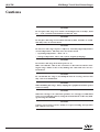
(M-) UTM
Mid-Range Travel
Steel Linear Stages
USER’S MANUAL
www.newport.com
(M-)UTM
Mid-Range Travel Steel Linear Stages
Warranty
Newport Corporation warrants this product to be free from defects in
material and workmanship for a period of 1 year from the date of shipment.
If found to be defective during the warranty period, the product will either
be repaired or replaced at Newport’s discretion.
To exercise this warranty, write or call your local Newport representative,
or contact Newport headquarters in Irvine, California. You will be given
prompt assistance and return instructions. Send the instrument, transportation prepaid, to the indicated service facility. Repairs will be made
and the instrument returned, transportation prepaid. Repaired products
are warranted for the balance of the original warranty period, or at least 90
days.
Limitation of Warranty
This warranty does not apply to defects resulting from modification or misuse of any product or part.
CAUTION
Warranty does not apply to damages resulting from:
• Incorrect usage:
– Load on the stage greater than maximum specified load.
– Carriage speed higher than specified speed.
– Improper grounding.
¬ Connectors must be properly secured.
¬ When the load on the stage represents an electrical risk, it must
be connected to ground.
– Excessive or improper cantilever loads.
• Modification of the stage or any part.
This warranty is in lieu of all other warranties, expressed or implied,
including any implied warranty of merchantability or fitness for a particular
use. Newport Corporation shall not be liable for any indirect, special, or
consequential damages.
No part of this manual may be reproduced or copied without the prior written approval of Newport Corporation.
This manual has been provided for information only and product specifications are subject to change without notice. Any changes will be reflected in
future printings.
EDH0156En1030 – 01/03
ii
(M-)UTM
Mid-Range Travel Steel Linear Stages
Table of Contents
Warranty .................................................................................................................ii
Table of Contents..................................................................................................iii
Warnings .................................................................................................................v
Cautions .................................................................................................................vi
1.0
— Introduction .................................................................................1
2.0
— Description ...................................................................................2
2.1 Design Details ............................................................................................3
3.0
3.1
3.2
3.3
3.4
3.5
4.0
— Characteristics ............................................................................3
Definitions ..................................................................................................3
Mechanical Specifications........................................................................4
Load Specification Definitions.................................................................4
Load Characteristics and Stiffness .........................................................5
Stage Weights ............................................................................................5
— Drive ................................................................................................6
4.1 Stepper Drive Versions.............................................................................6
4.2 DC-Servo Drive Versions ..........................................................................7
4.3 Manual Drive..............................................................................................7
5.0
5.1
5.2
5.3
5.4
5.5
5.6
5.7
6.0
— Motor ...............................................................................................8
Stepper Motor Characteristics ................................................................8
Command Signals for Stepper Motors....................................................8
DC-Motor Characteristics.........................................................................8
Command Signals for DC-Motors ............................................................8
Sensor Position..........................................................................................9
Feedback Signal Position..........................................................................9
Pinouts......................................................................................................10
— Connection to Newport Controllers ..............................11
6.1 Warnings on controllers.........................................................................11
6.2 Connection ...............................................................................................12
6.3 Cables .......................................................................................................12
7.0
— Connection to Non-Newport Controllers ....................14
iii
EDH0156En1030 – 01/03
(M-)UTM
Mid-Range Travel Steel Linear Stages
8.0
8.1
8.2
8.3
8.4
8.5
8.6
8.7
9.0
— Mounting......................................................................................15
Stage Mountings ......................................................................................15
Interfaces Disassembling .......................................................................15
Mounting on Working Surface ...............................................................17
Assembling by the Carriage...................................................................18
Disassembling..........................................................................................18
Interface Plates Mounting ......................................................................18
Assembly Pattern ....................................................................................18
— Dimensions .................................................................................19
10.0 — Accessories: EQ100 Brackets ............................................20
11.0 — Maintenance ..............................................................................21
11.1 Maintenance.............................................................................................21
11.2 Repairing ..................................................................................................21
11.3 Calibration................................................................................................21
Service Form .........................................................................................................22
We declare that the accompanying product, identified with the “
all relevant requirements of Directives:
• 73/23/EEC, for Low Voltage Compatibility.
• 89/336/EEC for Electromagnetic Compatibility.
” mark, meets
Generic standard:
Emission:
NF EN61326-1, for measurement, lab and control equipment.
Immunity:
NF EN61326-1, for measurement, lab and control equipment.
Safety:
EIC 1010-1, safety standards for measurement, lab and control
equipment.
Newport Corporation shall not be liable for damages when using the product:
• Modification of the product.
• Using modified connector, or modified or not supplied cables.
• Connecting this product to non-CE equipment.
EDH0156En1030 – 01/03
iv
(M-)UTM
Mid-Range Travel Steel Linear Stages
Warnings
WARNING
The translation of objects of all types carries potential risks for operators.
Ensure the protection of operators by prohibiting access to the dangerous
area and by informing the personnel of the potential risks involved.
WARNING
Do not use this stage when its motor is emitting smoke or is unusually
hot to the touch or is emitting any unusual odor or noise or is in any
other abnormal state.
Stop using the stage immediately, switch off the motor power and then
disconnect the electronics power supply.
After checking that smoke is no longer being emitted contact your
Newport service facility and request repairs. Never attempt to repair the
stage yourself as this can be dangerous.
WARNING
Make sure that this stage is not exposed to moisture and that liquid does
not get into the stage.
Nevertheless, if any liquid has entered the stage, switch off the motor
power and then disconnect the electronics from power supply.
Contact your Newport service facility and request repairs.
WARNING
Do not insert or drop objects into this stage, this may cause an electric
shock, or lock the drive.
Do not use this stage if any foreign objects have entered the stage. Switch
off the motor power and then disconnect the electronics power supply.
Contact your Newport service facility for repairs.
WARNING
Do not place this stage in unstable locations such as on a wobbly table or
sloping surface, where it may fall or tip over and cause injury.
If this stage has been dropped or the case has been damaged, switch off
the motor power and then disconnect the electronics power supply.
Contact your Newport service facility and request repairs.
WARNING
Do not attempt to modify this stage; this may cause an electric shock or
downgrade its performance.
WARNING
Do not exceed the usable depth indicated on the mounting holes (see
section “Dimensions”). Longer screws can damage the mechanics or
cause a short-circuit.
v
EDH0156En1030 – 01/03
(M-)UTM
Mid-Range Travel Steel Linear Stages
Cautions
CAUTION
Do not place this stage in a hostile environment such as X-Rays, hard
UV,… or in a vacuum environment less than 10-2 Torr.
CAUTION
Do not place this stage in a location affected by dust, oil fumes or steam.
This may cause an electric shock.
CAUTION
Do not leave this stage in places subject to extremely high temperatures
or low temperatures. This may cause an electric shock.
• Operating temperature: +10 to +35 °C.
• Storage temperature: -10 to +40 °C (in its original packaging).
CAUTION
Do not move this stage if its motor power is on.
Make sure that the cable to the electronics is disconnected before moving the stage. Failure to do so may damage the cable and cause an electrical shock.
CAUTION
Be careful that the stage is not bumped when it is being carried. This
may cause it to malfunction.
CAUTION
When handling this stage, always unplug the equipment from the power
source for safety.
CAUTION
When the carriage is in end-of-run position, it is strongly recommended
not to go beyond this point by using the manual knob as this may damage the stage mechanism.
CAUTION
Contact your Newport service facility to request cleaning and specification control every year.
EDH0156En1030 – 01/03
vi
(M-)UTM
Mid-Range Travel Steel Linear Stages
Mid-Range Travel Steel Linear Stages
(M-)UTM
1.0
Introduction
This manual provides operating instructions for the stage that you have
purchased in the (M-)UTM Series:
•
•
•
•
• (M-)UTMPE1V6 (1) • (M-)UTMCC.1
• (M-)UTMMS1
(1)
• (M-)UTMPE.1V6 • (M-)UTMCC1HL • (M-)UTMMS.1
• (M-)UTMCC1DD
• (M-)UTMCC.1DD
(M-)UTMPP1HL
(M-)UTMPP.1
(M-)UTMPE1
(M-)UTMPE.1
1)
REMARK
Vacuum compatible stages to 10-6 Torr. In this case, max. speed and load
capacity have to be divided by two.
(M-)UTM Series linear stages.
RECOMMENDATION
We recommend you read carefully the chapter “Connection to electronics” before using the (M-)UTM stage.
1
EDH0156En1030 – 01/03
(M-)UTM
2.0
Mid-Range Travel Steel Linear Stages
Description
The (M-)UTM Series translation stages feature steel construction with preloaded ball bearing slides and a backlash-compensated leadscrew for superior performance over medium travel ranges.
These motorized stages are equipped with mechanical limit switches to
prevent damage to the bearings from accidental overtravel. A center home
position allows the stage to be returned to a reference position in the middle of the stage’s travel at any time.
The home position (Mechanical Zero) may also be set to either end of the
stage’s travel via an external switch on the stage body:
+ : Origin, side opposite motor.
0 : Origin at stage center.
- : Origin on motor side.
Direction +
Direction +
Position measuring is performed with a 2000 pts/rev. encoder, integral with
the motor shaft and a 2 mm pitch backlash compensated leadscrew.
All (M-)UTM Series stages are equipped with a knurled knob for a manual control.
The modular design of (M-)UTM stages brings you the flexibility to choose
the drive configuration that best matches your specific application requirements: high-resolution 0.1 µm version or higher speed 1 µm version, manual, DC-motor or stepper motor driven versions, with mini-step or full-step
drive options.
For optimal performance, we recommend the use of our ESP or MM series
motion controllers.
The (M-)UTM Series stages are supplied with a 3-meter cable for connection to our motion controllers.
EDH0156En1030 – 01/03
2
(M-)UTM
Mid-Range Travel Steel Linear Stages
2.1
Design Details
Base Material
Bearings
Drive Mechanism
Drive Screw Pitch (mm)
Reduction Gear
Feedback
Limit Switches
Origin
Protection
Vacuum Compatibility
1)
3.0
Stainless Steel
Linear ball bearings
Backlash-compensated leadscrew
2
10:1 on all versions with 0.1 µm resolution (1)
2000 pts/rev. rotary encoder with index
pulse
Mechanical
Centered, can be set to left or right travel
limit via external switch
Bellows
Vacuum compatible versions are available
up to 10-6 Torr using full-step motor (PE1
and PE.1)
Additional motor mounted gear on some drive option.
Characteristics
3.1
Definitions
Specifications of our products are established in reference to ISO 230 standard part II “Determination of the position, precision and repeatability of
the machine tools with CNC”.
This standard gives the definition of position uncertainty which depends
on the 3 following quantities:
(Absolute) Accuracy
Difference between ideal position and real position.
On-Axis Accuracy
Difference between ideal position and real position after the compensation
of linear error sources.
Linear errors include: cosine errors, inaccuracy of screw or linear scale
pitch, angular deviation at the measuring point (Abbe error) and thermal
expansion effect. All Newport motion electronics can compensate for linear
accuracy errors by step encoder correction.
The relation between absolute accuracy and on-axis accuracy is as follow:
Absolute Accuracy = On-Axis Accuracy + Slope x Travel
Repeatability
Ability of a system to achieve a commanded position over many attempts.
Reversal Value (Hysteresis)
Difference between actual position values obtained for a given target position when approached from opposite directions.
Minimum Incremental Motion (Sensitivity)
Minimum motion that a stage can achieve. Our stages and our kinematic
chain are conceived in such a way that sensitivity is better than the resolution of the encoder.
3
EDH0156En1030 – 01/03
(M-)UTM
Mid-Range Travel Steel Linear Stages
Resolution
The smallest motion an encoder fixed to the stage can measure.
Yaw, Pitch
Rotation of carriage around the Z axis (Yaw) or Y axis (Pitch), when it
moves.
The testing of on-axis accuracy, repeatability, and reversal error are made systematically with our test equipment in an air-conditioned room (20 °C ±1 °C).
Each stage is tested with a laser interferometer.
A linear cycle with 21 measures on the travel and 4 cycles in each direction
gives a total of 164 points.
3.2
Mechanical Specifications
Travel Range
Unidirectional Repeatability
Reversal Value (Hysteresis)
On-Axis Accuracy (1)
αy Pitch (1)
αz Yaw (1)
1)
3.3
(mm)
(µm)
(µm)
(µm)
(µrad)
(µrad)
25; 50; 100 and 150
1.5
3.0 (PP1, PE1, CC1HL, CC1DD)
3.5 (PP.1, PE.1, CC.1, CC.1DD)
5.0
110
70
For a travel of 100 mm.
Load Specification Definitions
Normal Load Capacity (Cz)
Maximum load a stage can move while maintaining specifications.
This value is given with speed and acceleration specified for each stage,
and with a load perpendicular to bearings.
Axial Load Capacity (±Cx)
Maximum load along the direction of the drive train.
Off-Centered Load (Q)
Maximum cantilever-load a stage can move: Q ≤ Cz / (1 + D/50)
D:
Cantilever distance.
EDH0156En1030 – 01/03
4
(M-)UTM
Mid-Range Travel Steel Linear Stages
3.4
Load Characteristics and Stiffness
Cz
-Cx
+Cx
kαx
kαy
Z
D
Q
Cz
kα y
kα
x
Y
X
Q:
D:
Cz:
+Cx:
-Cx:
kαx:
kαy:
+ Cx
—C
x
3.5
(N)
(N)
(N)
(µrad/N.m)
(µrad/N.m)
200
10
50
10
15
Off-center load, Q ≤ Cz / (1 + D/50)
Cantilever distance in mm
Normal center load capacity on bearings
Direct load capacity on X axis
Inverse load capacity on X axis
Angular stiffness (Roll)
Angular stiffness (Pitch)
Stage Weights
Weights indicated into the below table are average values for stages with a
typical drive unit installed.
(M-)UTM25
(M-)UTM50
(M-)UTM100
(M-)UTM150
[lb (kg)]
[lb (kg)]
[lb (kg)]
[lb (kg)]
6.6 (3)
7.1 (3.2)
7.7 (3.5)
8.4 (3.8)
The weight variation between drive units is not very significant.
5
EDH0156En1030 – 01/03
(M-)UTM
4.0
Mid-Range Travel Steel Linear Stages
Drive
4.1
Stepper Drive Versions
Stepper-motor-driven stages are offered in four variants:
• Two mini-step drive versions with resolutions of 1 µm (PP1HL) and 0.1
µm (PP.1). These combine high speed positioning and smooth displacement from 1/10-stepper encoder count driving mode. For ultrasmooth
low-speed positioning, microstepping up to 250x is possible using ESP
Series Controllers.
• Two full-step versions with resolutions of 1 µm (PE1) and 0.1 µm (PE.1).
These are primarily designed for applications requiring the position to
be maintained within the stage’s resolution when power is switched off,
such as operation in vacuum.
Resolution
0.1 µm
Resolution
1 µm
(M-)UTMPP1HL
(M-)UTMPP.1
(M-)UTMPE1
(M-)UTMPE.1
Mini-Step Drive
Is used for stepper motors, when 1 pulse emitted by electronic corresponds to theoretical physical motion of a fraction of a full step of the
motor.
For these stages a mini-step equals 1/10 of a full step.
Full-Step Drive
Is used for stepper motors, when 1 pulse emitted by electronic corresponds to theoretical physical motion of 1 full step of the motor.
Stepper Motor Performance Specifications
Resolution
Speed
(µm)
(mm/sec)
(M-)UTMPP1HL
1
20
(M-)UTMPP.1
0.1
2
(M-)UTMPE1
1
2
(M-)UTMPE.1
0.1
0.2
EDH0156En1030 – 01/03
6
Motor
UE41PP
UE31PP
(M-)UTM
Mid-Range Travel Steel Linear Stages
4.2
DC-Servo Drive Versions
Four DC-motor-driven configurations are available:
• Two high-power DC-Servo versions with resolutions of 1 µm (CC1HL)
and 0.1 µm (CC.1). The CC1HL features a built-in tachometer to provide
superior speed stability.
• Two low-power versions with resolutions of 1 µm (CC1DD) and 0.1 µm
(CC.1DD). These stages offer a cost-effective performance alternative for
those who have precision positioning needs with budget limitations.
Resolution
0.1 µm
(M-)UTMCC.1
Resolution
1 µm
(M-)UTMCC1DD
(M-)UTMCC.1DD
(M-)UTMCC1HL
DC-Motor Performance Specifications
Resolution
(µm)
(M-)UTMCC.1
0.1
(M-)UTMCC1HL
1
(M-)UTMCC1DD
1
(M-)UTMCC.1DD
0.1
4.3
Speed
(mm/sec)
2
20
2.5
0.25
Motor
UE33CC
UE404CC
UE31CC
Manual Drive
Two manual drive versions are available with resolutions of 1 µm (MS1)
and 0.1 µm (MS.1). In addition to the vernier scale on the manual drive,
position may be determined using the output from the incremental shaft
encoder. A connector for the CV1000 encoder display is provided.
Resolution
0.1 µm
Resolution
1 µm
Manual Performance Specifications
Resolution
(µm)
(M-)UTMMS1
1
(M-)UTMMS.1
0.1
7
(M-)UTMMS1
(M-)UTMMS.1
Travel per Revolution
(mm/rev.)
2
0.2
EDH0156En1030 – 01/03
(M-)UTM
5.0
Mid-Range Travel Steel Linear Stages
Motor
5.1
Stepper Motor Characteristics
Angle by Step
(°)
3.6
1.8
Motor
UE31PP
UE41PP
Current
(A)
0.56
1.2
5.2
Resistance
(Ω)
7.6
3
Inductance
(mH)
8.4
4.3
Command Signals for Stepper Motors
Command Signals
UE41PP
Command Signals
UE31PP
1
2
3
4
1
Phase 1
Phase 1
Phase 2
Phase 2
Phase 3
Phase 3
Phase 4
Phase 4
Direction –
Newport
Utilization
Full-Step
Full-Step or Mini-Step
Displacement
Direction +
2
3
Direction –
4
Displacement
Direction +
Direction +
Direction +
5.3
Motor
UE31CC
UE33CC
UE404CC
Mechanical Power
(W)
2.53
23
40
5.4
DC-Motor Characteristics
Nominal Voltage
(V)
24
36
75
Armature Resistance
(Ω)
57
14
18.6
Tachometer
(V/Krpm)
–
–
3 (±10%)
Command Signals for DC-Motors
+ Motor
+ Tachometer
+V
– Motor
– Tachometer
–V
+ Motor
+ Tachometer
Displacement
– Motor
– Tachometer
+ Direction
+V
–V
– Direction
Displacement
Direction +
Direction +
In the above drawings, + Motor signal is referred to – Motor signal, + Tacho
Generator signal is referred to – Tacho Generator signal.
EDH0156En1030 – 01/03
8
(M-)UTM
Mid-Range Travel Steel Linear Stages
➊ When the stage moves in + Direction, the + Motor voltage is higher than
– Motor voltage, and + Tacho Generator voltage is higher than – Tacho
Generator voltage.
➋ When the stage moves in – Direction, the + Motor voltage is lower than
– Motor voltage, and + Tacho Generator voltage is lower than – Tacho
Generator voltage.
5.5
Sensor Position
Home Position (Origin)
at Center of Travel Range
– EOR Limit
+ EOR Limit
Mechanical
Zero
Index Pulse
Index Pulse
Stage Travel Range
Motion
Direction +
End-of-Run and Mechanical Zero are TTL type: 5 V ±5%, 2 mA max.
Use of the Index Pulse provides a repeatable Home Position at ±1 step.
CAUTION
“End-of-Run” and “Mechanical Zero” are active signals and should not be
connected to any other source. Use appropriate TTL type receivers.
5.6
Feedback Signal Position
1
Encoder
Phase A
Encoder
Phase A
Encoder
Phase B
Encoder
Phase B
2
3
4
1
0
1
0
1
Direction +
0
1
Direction +
0
Direction –
Motion
Direction +
The incremental sensor operates following the photoelectric measurement
principle, with a disk including slides. When the sensor shaft turns, the sensor generates square signals in quadrature, sent to pins #19, #20, #23 and
#24 of the 25-pin Sub-D connector.
9
EDH0156En1030 – 01/03
(M-)UTM
Mid-Range Travel Steel Linear Stages
Newport
Stage
User
Encoder Phase A
Pin #19
Encoder Phase A
Pin #23
Encoder Phase B
Pin #20
Encoder Phase B
Pin #24
Index Pulse Phase I
Pin #15
Index Pulse Phase I
Pin #25
Output Signals
Pin #21
+5 V ±5%
150 mA max.
Pin #22
5.7
0V
}
Encoders
& Sensors
Power Supply
Pinouts
The 25-pin Sub-D connection for the (M-)UTM stages is given in the following table:
14
25
1
13
UE31PP:
UE31CC:
(M-)UTMPE1 & PE.1
(M-)UTMCC1DD & CC.1DD
UE404CC:
Manual:
(M-)UTMCC1HL
(M-)UTMMS1 & MS.1
UE41PP:
UE33CC:
(M-)UTMPP1HL & PP.1
1
Phase 1
1
(M-)UTMCC.1
N.C.
1
+ Tachometer
1
N.C.
2
Phase 1
2
N.C.
2
+ Tachometer
2
N.C.
3
Phase 2
3
N.C.
3
– Tachometer
3
N.C.
4
Phase 2
4
N.C.
4
– Tachometer
4
N.C.
5
Phase 3
5
+ Motor
5
+ Motor
5
N.C.
6
Phase 3
6
+ Motor
6
+ Motor
6
N.C.
7
Phase 4
7
– Motor
7
– Motor
7
N.C.
8
Phase 4
8
– Motor
8
– Motor
8
N.C.
9
Common Phase 3-4
9
N.C.
9
N.C.
9
N.C.
10
N.C.
10
N.C.
10
N.C.
10
N.C.
11
Common Phase 1-2
11
N.C.
11
N.C.
11
N.C.
12
N.C.
12
N.C.
12
N.C.
12
N.C.
13
Mechanical Zero
13
Mechanical Zero
13
Mechanical Zero
13
Mechanical Zero
14
Shield Ground
14
Shield Ground
14
Shield Ground
14
Shield Ground
15
Index Pulse I
15
Index Pulse I
15
Index Pulse I
15
Index Pulse I
16
0 V logic
16
0 V logic
16
0 V logic
16
0 V logic
17
+ End-of-Run
17
+ End-of-Run
17
+ End-of-Run
17
+ End-of-Run
18
– End-of-Run
18
– End-of-Run
18
– End-of-Run
18
– End-of-Run
19
Encoder Phase A
19
Encoder Phase A
19
Encoder Phase A
19
Encoder Phase A
20
Encoder Phase B
20
Encoder Phase B
20
Encoder Phase B
20
Encoder Phase B
21 Encoder Power: +5 V
21 Encoder Power: +5 V
21 Encoder Power: +5 V
21 Encoder Power: +5 V
22
0 V Encoder
22
0 V Encoder
22
0 V Encoder
22
0 V Encoder
23
Encoder Phase /A
23
Encoder Phase /A
23
Encoder Phase /A
23
Encoder Phase /A
24
Encoder Phase /B
24
Encoder Phase /B
24
Encoder Phase /B
24
Encoder Phase /B
25
Index Pulse /I
25
Index Pulse /I
25
Index Pulse /I
25
Index Pulse /I
EDH0156En1030 – 01/03
10
(M-)UTM
6.0
Mid-Range Travel Steel Linear Stages
Connection to Newport Controllers
6.1
Warnings on controllers
Controllers are intended for use by qualified personnel who recognize
shock hazards and are familiar with safety precautions required to avoid
possible injury. Read the controller user’s manual carefully before operating the instrument and pay attention to all written warnings and cautions.
WARNING
Disconnect the power plug under the following circumstances:
• If the power cord or any attached cables are frayed or damaged in
any way.
• If the power plug is damaged in any way.
• If the unit is exposed to rain, excessive moisture, or liquids are spilled
on the unit.
• If the unit has been dropped or the case is damaged.
• If you suspect service or repair is required.
• Whenever you clean the electronics unit.
CAUTION
To protect the unit from damage, be sure to:
• Keep all air vents free of dirt and dust.
• Keep all liquids away from the unit.
• Do not expose the unit to excessive moisture (>85% humidity).
• Read this manual before using the unit for the first time.
WARNING
All attachment plug receptacles in the vicinity of this unit are to be of the
grounding type and properly polarized.
Contact your electrician to check your receptacles.
WARNING
This product is equipped with a 3-wire grounding type plug.
Any interruption of the grounding connection can create an electric
shock hazard.
If you are unable to insert the plug into your wall plug receptacle, contact your electrician to perform the necessary alterations to ensure that
the green (green-yellow) wire is attached to earth ground.
WARNING
This product operates with voltages that can be lethal.
Pushing objects of any kind into cabinet slots or holes, or spilling any
liquid on the product, may touch hazardous voltage points or short out
parts.
11
EDH0156En1030 – 01/03
(M-)UTM
Mid-Range Travel Steel Linear Stages
6.2
Connection
On each stage is represented a label which indicates its name, its serial
number and the motor it is equipped with (ex.: UE31PP).
M-UTM100PE.1
ENCODER:5V
Stepper Motor
S/N#
MOTOR:UE31PP
U=30VDC I=1A
WARNING
Always turn the controller's power OFF before connecting to a stage.
Stages may be connected to the rear panel motor connectors labeled
“Motor…” any time prior to power-up with the supplied cable assemblies.
WARNING
With MM series controllers, damage to stage may occur if the stage is not
the same type as shown on driver label located near the stage interface
connector.
Check that the option number specified on this label correspond to the
number indicated in the driver module options table for your stage.
WARNING
Vacuum compatible stages have to be configured if running with an ESP
series controller.
6.3
Cables
All our (M-)UTM stages are delivered equipped with a 3-meter cable with
25-pin Sub-D connectors so they can be directly connected to our controllers/drivers of MM or ESP series.
Dimensions in inches (millimeters)
Locking
Knobs
ø .41
(ø 10.3)
25-Pin Sub-D
Connector
2.13
(54)
2.32 (59)
Disconnected
4.1 (104) for a static cable
6.54 (166) for a cable in motion with the stage
WARNING
This cable is shielded correctly. For a correct operation, make sure to
lock connectors (ground continuity provided by the cable).
EDH0156En1030 – 01/03
12
(M-)UTM
Mid-Range Travel Steel Linear Stages
For applications where the standard 3-meter cable (MMCABLE-3) included
with your stage is not adequate, Newport offers longer length cables
designed to ensure the integrity of your positioning application.
These cables are specially shielded and terminated with Newport’s standard 25-pin sub-D connectors. They are available in 5-m (MMCABLE-5), 7-m
(MMCABLE-7) or 10-m (MMCABLE-10) lengths.
WARNING
Keep the motor cables at a safe distance from other electrical cables in
your environment to avoid potential cross talk.
For cable lengths in excess of 3 meters, we recommend the MMCABLE-REG
to ensure a high quality, regulated 5 V supply to the stages.
Dimensions in inches (millimeters)
25-Pin Sub-D
Male
25-Pin Sub-D
Female
2.1
(54)
2.4 (62)
This regulator is available as an option. Please note that for best efficiency,
this regulator should be attached to the stage to re-adjust the 5 volts coming from the controller through the long cable.
13
EDH0156En1030 – 01/03
(M-)UTM
7.0
Mid-Range Travel Steel Linear Stages
Connection to Non-Newport Controllers
WARNING
Newport takes no responsibility for improper functioning or damage of a
stage when it is used with any non- Newport controllers.
WARNING
Newport guarantees the “
” compliance of the (M-)UTM translation
stages only if they are used with Newport cables and controllers.
Nevertheless, the figure below indicates the recommended wiring when
a (M-)UTM stage is used with non-Newport controllers.
Sub-D25 male
Connector
Connection
(M-)UTMPP & PE
9
10
11
12
Connection
(M-)UTMCC & CCDD
Connection
(M-)UTMCC1HL
Common Phase 3-4
N.C.
Common Phase 1-2
N.C.
N.C.
N.C.
N.C.
N.C.
N.C.
N.C.
N.C.
N.C.
1
2
3
4
Phase 1
Phase 1
Phase 2
Phase 2
N.C.
N.C.
N.C.
N.C.
+ Tachometer
+ Tachometer
– Tachometer
– Tachometer
5
6
7
8
Phase 3
Phase 3
Phase 4
Phase 4
+ Motor
+ Motor
– Motor
– Motor
+ Motor
+ Motor
– Motor
– Motor
14
Ground
Ground
Ground
0 V logic
Mechanical Zero (*)
Encoder Phase A
Encoder Phase /A
Encoder Phase B
Encoder Phase /B
Index Pulse I
Index Pulse /I
+ End-of-Run (*)
– End-of-Run (*)
+5 V Encoder
0 V Encoder
Connector
Cap
0 V logic
Mechanical Zero (*)
Encoder Phase A
Encoder Phase /A
Encoder Phase B
Encoder Phase /B
Index Pulse I
Index Pulse /I
+ End-of-Run (*)
– End-of-Run (*)
+5 V Encoder
0 V Encoder
Connector
Cap
0 V logic
Mechanical Zero (*)
Encoder Phase A
Encoder Phase /A
Encoder Phase B
Encoder Phase /B
Index Pulse I
Index Pulse /I
+ End-of-Run (*)
– End-of-Run (*)
+5 V Encoder
0 V Encoder
Connector
Cap
16
13
19
23
20
24
15
25
17
18
21
22
Connector
Cap
* Open collector type with a 5.6 V protective Zener diode.
End-of-Run or Mechanical Zero:
Max. Iin: 16 mA
Max. V: 5.6 V
Newport
Stage
5.6 V
If the “Mechanical Zero” output is not used, a 1 kΩ/0.25 W resistor must
be connected between pins #13 and #21.
“Encoder” and “Index Pulse” are “differential pair” type output signals.
Using these signals permits a high immunity to noise. Emission circuits
generally used by Newport are 26LS31 or MC3487. Reception circuits to use
are 26LS32 or MC3486.
EDH0156En1030 – 01/03
14
(M-)UTM
8.0
Mid-Range Travel Steel Linear Stages
Mounting
8.1
Stage Mountings
WARNING
Before to use a (M-)UTM stage, it is imperative to fix it:
• directly on a rectified working surface, from holes located on the
mounting plate,
• on another stage, directly or with a mounting interface.
but in no case, the stage has to remain without fastening.
It is equally necessary to fasten the device to move on the carriage:
• directly,
• removing the plate on the top of the stage.
4 holes Ø .27 (6.8)
on 6.0 x 2.0 (152.4 x 50.8)
Base plate
4 holes Ø .27 (6.8)
on 5.9 x 3.9 (150 x 100)
UTM:
9 holes 1/4-20 thd, 1.0 (25.4) spacing
M-UTM:
9 holes M6 thd, .98 (25) spacing
Top plate
on the carriage
Dimensions in inches (millimeters)
CAUTION
The working surface flatness directly influences stage accuracy and performance.
8.2
Interfaces Disassembling
➊ Disassemble the top plate fixed on the carriage of the stage with 4 CHc
M4 x .39 in. (10 mm) screws / 2.48 in. (63 mm).
15
EDH0156En1030 – 01/03
(M-)UTM
Mid-Range Travel Steel Linear Stages
➋ Turn the stage upside down.
➌ Disassemble the base plate fixed on the body of the stage with 4 CHc
M4 x .39 in. (10 mm) screws / 2.48 in. (63 mm).
EDH0156En1030 – 01/03
16
(M-)UTM
Mid-Range Travel Steel Linear Stages
8.3
Mounting on Working Surface
➊ Rotate the manual knob to move the carriage to provide access to the 2
holes on the bottom of the stage.
➋ Fasten the stage on the working surface with 2 M-CAP-M41 captive
screws.
➌ Move the carriage to access the other 2 holes on the bottom of the
stage.
➍ Fasten the stage on the working surface with 2 M-CAP-M41 captive
screws.
CAUTION
To fasten (M-)UTM stages, use only M-CAP-M41 captive screws, especially
devised.
Mounting on Stage
Mounting on Carriage
Ø .29
(7.5)
M4 thd
.18 (4.6)
Carriage
.22 (5.5)
Stage
Ø .29
(7.5)
M4 thd
Dimensions in inches (millimeters)
17
EDH0156En1030 – 01/03
(M-)UTM
Mid-Range Travel Steel Linear Stages
CAUTION
When mounting (M-)UTM stage on working surface, the depth of the M4
threaded holes of the working surface must be deeper than 8 mm. Protr
uding captive screws will damage the carriage.
Before power on motor stage, make a displacement try with the knurled
knob, to verify that the displacement of the carriage is correct.
8.4
Assembling by the Carriage
Make steps of “Mounting on Working Surface” chapter in the same order.
8.5
Disassembling
Make steps of “Mounting on Working Surface” chapter in the opposite
order.
8.6
Interface Plates Mounting
Make steps of “Interfaces Disassembling” chapter in the opposite order.
8.7
Assembly Pattern
Stacking (M-)UTM Series stages either together or with other Newport stage
is easily accomplished. Below are example schematics of the assembly patterns used. These interfaces are accessed by unscrewing and removing the
upper and/or lower plates of the stages (see dimension drawing).
4 holes M4 thd / 63,
depth: 6
Carriage
Interface
4 holes ø 7.5:
Access for captive screws
used in mounting to body
6
2.5
4 holes M5 thd
on / 92,
depth: 6
Stage
Interfaces
4 holes M4 thd
on / 63,
depth: 6
ø 32
Dimensions in Millimeters
EDH0156En1030 – 01/03
Neck for BR4
mounting clamp
18
4 holes ø 7.5:
Access for captive screws,
used in mounting to carriage
(M-)UTM
9.0
Mid-Range Travel Steel Linear Stages
Dimensions
DC Servo Drive
L2
4 HOLES, ø 6.8
on 152.4 x 50.8
MODEL UTM100PP1HL SHOWN
Dimensions in millimeters
48
9 HOLES, THD A,
B SPACING
Stepper Drive
105
76
170
25 PIN SUB-D
CONNECTOR
L2
120
8
4 HOLES, ø 6.8
on 150 x 100
8
78
H max.
24
Manual Drive
7
L1
L2
Model (Metric)
UTM (M-UTM)
Thread
A
1/4-20 (M6)
Dimension
[in. (mm)]
B
1.0 (25)
Travel [in. (mm)]
L1 [in. (mm)]
.98 (25)
6.1 (155)
1.97 (50)
7.1 (180)
3.9 (100) 5.9 (150)
9.1 (230) 11.0 (280)
UTM (M-UTM)
MS1
MS.1
PP1HL
PP.1
PE1
PE.1
CC.1
CC1HL
CC1DD
CC.1DD
Dimension [in. (mm)]
L2
H
4.0 (100.5)
1.26 (32)
5.6 (141.5)
1.26 (32)
3.6 (90.5)
1.65 (42)
5.2 (131.5)
1.65 (42)
5.5 (139)
1.26 (32)
7.1 (180)
1.26 (32)
5.2 (133)
1.91 (48.5)
5.8 (148)
1.91 (48.5)
4.6 (116.5)
1.26 (32)
6.2 (157.5)
1.26 (32)
(M-)UTM Series XY assemblies are an economical choice when precision
motion for light loads is required. These stages can be aligned to within
50 µrad orthogonality.
19
EDH0156En1030 – 01/03
(M-)UTM
10.0
Mid-Range Travel Steel Linear Stages
Accessories: EQ100 Brackets
EQ100 Series right-angle brackets (to order separately) can be used for vertical mounting configurations of a (M-)UTM stage.
4 HOLES,
M4 CLR / 63
ø 50
B
Model
EQ100-S
EQ100-L
Dimension [in. (mm)]
A
B
C
5.3 (135)
5.1 (130.5)
4.1 (105)
8.5 (215)
5.9 (144)
6.9 (174)
108
73
A
C
6
6
119.4
Dimensions in millimeters.
Model
Description
EQ100-S
EQ100-L
Right-Angle Bracket for (M-)UTM25/50
Right-Angle Bracket for (M-)UTM100/150
(M-)UTM X-Z assemblies can be aligned to within
50 µrad orthogonality and can provide up to
150 mm of travel.
EDH0156En1030 – 01/03
20
(M-)UTM
11.0
Mid-Range Travel Steel Linear Stages
Maintenance
RECOMMENDATION
It is recommended to contact our After Sales Service which will be able
to define the appropriate maintenance for your application.
11.1
Maintenance
The (M-)UTM stage requires no particular maintenance. Nevertheless, this
is a precision mechanical device that must be kept and manipulated with
precaution.
PRECAUTIONS
The (M-)UTM stage must operate, and be stocked in a clean environment,
without dust, humidity, solvents or other substances.
RECOMMENDATION
It is recommended to return your stage to our After Sales Service after
every 2000 hours of use for lubrication.
If your (M-)UTM stage is mounted on a workstation and cannot be easily
dismantled, please contact our After Sales Service for further instructions.
11.2
Repairing
CAUTION
Never attempt to disassemble an element of the stage that has not been
specified in this manual.
Disassembling a non specified element can cause a malfunction of the
stage.
If you observe a malfunction in your stage, please immediately contact us
to make arrangements for a repair.
CAUTION
All disassembly attempts or repair of stage without authorization will
void your warranty.
11.3
Calibration
CAUTION
It is recommended to return your stage to Newport once a year for a
recalibration to its original specifications.
21
EDH0156En1030 – 01/03
Service Form
Your Local Representative
Tel.:
Fax:
Name:
Return authorization #:
(Please obtain prior to return of item)
Company:
Address:
Date:
Country:
Phone Number:
P.O. Number:
Fax Number:
Item(s) Being Returned:
Model #:
Serial #:
Description:
Reasons of return of goods (please list any specific problems):
EDH0156En1030 – 01/03
22
(M-)UTM
Mid-Range Travel
Steel Linear Stages
CE Declaration of Conformity
We declare that the accompanying product, identified with the
“ ” mark, meets all relevant requirements of Directive:
• 73/23/CEE, for Low Voltage Compatibility.
• 89/336/EEC for Electromagnetic Compatibility.
Compliance was demonstrated to the following specifications:
EMISSION:
Radiated and Conducted Emission in accordance with
relative prescription to the EMC, NF EN61326-1: Standards
for measurement, lab and control equipment.
IMMUNITY:
Radiated and Conducted Immunity in accordance with
relative prescription to the EMC, NF EN61326-1: Standards
for measurement, lab and control equipment.
SAFETY:
CEI 1010-1, safety standards for measurement, lab and
control equipment.
Jean-Marc DELAHAYE
Quality Director
Zone Industrielle
45340 Beaune-la-Rolande, France