1
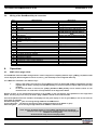
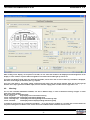
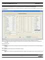
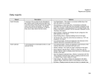
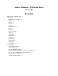
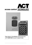
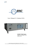
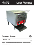
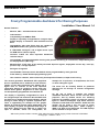
DashBoard LED
Freely Programmable dashboard for Racing Purposes
Installation / User Manual 1.4
General Features:
-
Massive, CNC – etched aluminum chassis
-
CAN interface
-
Compatibility with ASMoto ECU:
Display is separately configurable for 4 engine maps.
Simple display of numerous data available from the
ECU
-
Compatibility with other ECUs that are capable of
AIM (RS232 19200,n,8,1) protocol data transfer
-
6 calibratable analogous- and 2 digital sensor input
for RPM and Vs (Vehicle speed)
-
Contains in-built the most important dashboard
indicator lamps.
-
Customizable and acknowledgeable warning with parallel monitoring of 12 channels, independently from
the displayed data (Warning)
-
Measurement of lap time, 8 lap memory-recorded lap-time register, displayable current lap-, best lap-,
previous lap-, average lap times
-
Shift gear recognition
-
Customizable shift lamp control with default values programmable by each gearshift
-
Flash memory. 100000 deletion/programming cycles
-
User interface software, with continuously developed free firmware, simple electric wiring
The second generation DashBoard LED equipment
kit was expanded with a multitude of new features.
Thanks to the LED technology the display has a
higher level of contrast so the most important
information among all conditions can be read even
without direct glance. Brightness of each segment
can be separately programmed and switched off.
The display is separately configurable for each of
the 4 engine maps and numerous data available from
the ECU can be displayed through CAN bus, without
having to install wiring to separate equipment kits.
There is opportunity for example for the graphic
display of round per minute, water temperature, fuel
level, display of speed and gearshift and usage of
shift lamp. Apart from the CAN bus a further 6+2
input is available, which are configurable, for
example for oil pressure, oil temperature, fuel level
or other analogous signal.
The driver can be instantly alerted on problems
affecting the car through 12 channel configurable
warnings.
On the top of these it contains the general
dashboard indicators which can be used for other
purposes, but by default serves the following
purposes for example: charge, oil pressure, position
lights or dimmed headlights, high beam, direction
indicators, brake fluid level indicator. Under the LED
display can be found a two row LCD on which
further configurable data (even 3data x 2page x
4MAP = 24 data) can be displayed. The LED displays
can be ordered in unique colors.
Without the previous written consent of the author the full or partial copying of this document is forbidden!
© Copyright – ASMoto – 2014
2014
www.asmoto.eu - [email protected]
DashBoard LED
ASMoto DashBoard LED
2.
Brochure 1.4
Technical details:
Electrical:
Suppy voltage:
Standby power: (without sensors, in case of 12V)
Load on output of „11 pin” sensors + 4,5V supply
Power range of analogous inputs: (for normal operation use)
Power range of analogous inputs: (without permanent damage)
Mechanical:
Width:
Length: (without connector)
Height:
Mass:
Usage conditions:
Operational temperature:
Storage temperature:
3.
Min.:
8
200
0
-20
Min.:
Min.:
-30
-40
Norm.:
14
300
0,1-4,9
0,1-4,9
Norm.:
175
37.5
127.3
700
Norm.:
-
Max.:
20
400
100
5
20
Max.:
Max.:
70
90
Unit:
V
mA
mA
V
V
Unit:
mm
mm
mm
g
Unit:
°C
°C
Wiring diagram:
Picture no. 3.10. (A bigger resolution, printable version of the picture can be found on the website www.asmoto.eu under menu item
titled Download)
DasdBoard LED
www.asmoto.eu
-2-
ASMoto DashBoard LED
3.2.
Brochure 1.4
Wiring of the DashBoard 24 pin connector:
Pin:
1
2
3
4
5
6
Name/function:
CAN L
AN1 CH1
AN2 CH2
AN3 CH3 fuel level
AN4 CH4
AN6 CH6
7
D IN RPM signal, or RS232 RX signal input for Ext. ECU
8
9
10
D IN Speed
GND
Ignition + (15th pin)
+5V output for power supply for the sensors (max:
80mA)
Page Select button
CAN H
Left direction indicator
Oil pressure switch
Generator indicator/ charge indicator
MIL (Malfunction Indicator) lamp
Low brake fluid level indicator
Left direction indicator
High beam indicator
Position lights or dimmed headlights indicator
Permanent + power supply (30th pin)
AN5 CH5
Lap Time button
11
12
13
14
15
16
17
18
19
20
21
22
23
24
4.
Operation:
4.1.
MAP select, page select:
Description:
CAN Bus Low
Analog input with 4.7kΩ Pull-up to 5V
Analog input with 4.7kΩ Pull-up to 5V
Analog input with 100Ω Pull-up to 5V
Analog input with 4.7kΩ Pull-up to 5V
Analog input with 4.7kΩ Pull-up to 5V
Digital input with 1kΩ Pull-down to
GND
Digital input with 4.7kΩ Pull-up to 5V
Digital input with 10kΩ Pull-up to 5V
CAN Bus High
33ohm -> Ignition+ 10pin
Analog input with 4.7kΩ Pull-up to 5V
Digital input with 10kΩ Pull-up to 5V
The DashBoard contains 4 MAPs through which it can be configured in completely different ways. ([A.Map:] 1-4) Different data
can be displayed, different brightness can be set, also e.g. the shift-lamp can be configured differently.
The 4 MAPs are selectable in two different ways:
1.
2.
Putting a tick mark in the tick box at ’Active MAP from ECU’ the Active MAP [A.Map:] automatically changes
together with the ECU’s currently selected MAP [A.M:E:] (of course this feature requires CAN connection with
the ECU)
In case the tick mark is removed, the [A.Map:] DashBoard MAP [A.M:D:] will be followed, which we can
increment from 1 to 4 with the 3 second pushdown of the Page Select button.
Besides of these we can step between two pages in the 4 MAPs on the LCD with the short pushdown of the Page Select
button. This way only on the LCD up to 3data x 2page x 4MAP = 24 data can be made available.
From the dropdown menus the variable to be displayed on the given display in case of given MAP (in case of LCD even the
given page) is selectable.
Variables ending with …_ECU are arriving through CAN from the ASMoto ECU.
Those ending with …_Ext_ECU are arriving from other manufacturers ECU on the RS232 –n (pin7).
Data ending with …_TC are arriving through CAN from the ASMoto TractionControl.
Attention!
In the „Source” dropdown menus (in case of Maps and Warning) we should pay
attention to the origin of the chosen variables (where the to-be-displayed
variables are arriving from)
At the end of the setup check all displayed data!
DasdBoard LED
www.asmoto.eu
-3-
ASMoto DashBoard LED
Brochure 1.4
After clicking on the display, on the picture’s left side, we can select the variable to be displayed and the brightness of the
display. In case of LED or 10 piece LED-line brightness and values where LEDs light up can be set.
The lower LCD display’s both pages are optionally selectable, can be 3x6 or 2x9. In case of 2x9 only 2 variables is displayed,
but those can be longer (9 characters) like e.g.: lap-time.
If we put a tick mark to „Use power voltage controlled charge lamp” than the charge indicator lamp will not only light up
because of the 16pin generator feedback input, but also when the supply power is under 13V for longer than 1 sec.
4.2.
Warning:
The 12, user choosable DashBoard variables, can alert in different ways, in case of threshold crossing of upper- or lower
limits set to each variable.
We can choose from 4 warning levels:
1 level: only write
Only displays text on threshold crossing
2 level: +blacklight blink Text display with blinking background
3 level: +warning lamp Text display with blinking background and warning lamp
4 level: +full blink
Text display with full display blinking and warning lamp
2 conditions can be tied to all 12 channels (Condition 1 - 2). In case we tie a condition to a channel then on that channel we
only have warning if the condition is met. In case we tie two conditions both conditions have to be met.
DasdBoard LED
www.asmoto.eu
-4-
ASMoto DashBoard LED
Brochure 1.4
(This way it can be prevented that there is e.g. a warning because of low oil pressure at a standing engine.
The 13th warning channel monitors the oil pressure switch and if it would warn above the set RPM we can have the whole
display blinking.
Source: A condition on the lower (min) and upper (max) limits can be set for the chosen variable for the warning.
Min-max: Crossing these thresholds triggers a warning. (In case set conditions are met and „Exceed. time” parameter was
exceeded)
Units: measuring unit.
Exceed. time [s]:
Setting of the time duration in seconds for which the lower and upper values (conditions) will be exceeded to trigger a
warning.
Mark time [s]:
Duration of the warning can be set, expressed in seconds.
Remarking [s]:
Can be set in seconds how long the system should wait to trigger a warning again (only in case the condition is still
met)
DasdBoard LED
www.asmoto.eu
-5-
ASMoto DashBoard LED
Brochure 1.4
All warning alert can be acknowledged with the Page select button, 2 seconds after the appearance of the warning on the
display. (The 2 second delay is necessary to prevent accidental acknowledgement of warnings). In this case the given
warning will not alert again until the condition that triggered the warning is not met anymore and then met again, or after the
switching off and on of the DashBoard.
4.3.
Lap time:
The DashBoard is equipped with an 8 lap memory-recorded lap-time register. Every impulse arriving to the Lap time (24pin)
input the ActLapNumber [ActLaN] variable is increased with one and this shows in which lap we are. The photocell or the
transponder can be wired here. Time of the current lap can be seen at the [ActLap]. As a result of the impulse it is saved to
the memory. After the 8th lap the 1 gets overwritten.
With depressing the Lap time button for 3 seconds the previous 8 lap’s time, best lap, average lap-time and total lap-time can
be displayed on the LCD. In this case the ActLapNumber will not increase as a result of the impulses and page change is not
possible, but we can switch between the lap times up and down with the two buttons. With the parallel 2 second depression
of the two buttons we can delete the lap-time memory. With the depression of the Lap time button for 3 seconds we can exit
the lap-time memory display.
4.4.
Shift lamp:
The DashBoard offers several different opportunities for indication of gearshifts. With choosing the RPM... variable to the
upper horizontal scale it is configurable for all the 10 segments at which RPM they each should light up and for every
gearshift we can set a value that will be a threshold and when crossed we can have the whole scale blinking together with the
gearshift display.
For every gearshift the RPM at which blinking should start can be separately set. Similarly it can be selected that from which
variable the DashBoard should calculate for this the gear and RPM.
4.5.
Using the ASMoto CAN network:
In case of using together with the ASMoto ECU, the ECU send 13 data through CAN bus, (details in the ASMoto CAN protocol
documentation) so wiring these separately to the equipment kit is not necessary.
Here are 3 examples:
[in square brackets the name as we can find it in the dropdown menu of the AREM]
Round per minute [RPM_ECU]
Water temperature [Water_temp_ECU]
Exhaust gas temperature [ECT_ECU]
Besides of this of course there is possibility to use analogous- and 2 digital input, where further sensors can be wired, e.g.
fuel-level, oil pressure, etc. These sensors need to be calibrated so that real values are shown on the displays.
4.6.
ASMoto without a CAN network:
The sensors wired to the 6 analogous input can be calibrated so the displayed value (e.g.: temperature, pressure) becomes
easily readable. The two digital inputs are set up for accepting RPM and wheel speed data.
4.7.
Calibration of Sensors:
1.
Select the ANx input where the sensor which is desired to be calibrated was wired. (Channels)
2.
Choose the variable in which we would like to see the result (Source)
3.
Generate the smallest and biggest values which we would like to measure with the sensor (in case of temperature
sensor heat it up and cool it down), and write these two A/D values to the two ends of the A/D value range. (The
software interpolating between the two values fills in the upper table)
DasdBoard LED
www.asmoto.eu
-6-
ASMoto DashBoard LED
Brochure 1.4
Create again as possible the upper A/D range values, and write under all values the corresponding quantities (in case of
temperature sensor the temperature expressed in C°).
4.
4.8.
With the Write to Dashboard button we can write all set parameters (Maps, Sensor Calibration, Warnings) into the
Dash.
Gearshift position recognition / Gear sensor calibration:
4.8.1
In case we have power level proportionate to the gearshift position from the gearshift wire it to any of the
analogous inputs (CH1-CH6) .
For this choose „Use analog CH input:”, and besides select the AN CH x channel we wired the sensor to. Write
this AN CH x value on any of the displays, then shifting the gear to each position one after another determine and
write in the min and max values.
4.8.2
In case we do not have a signal available for the gearshift position the DashBoard can deduce it from the
proportion of the RPM and the speed. (Use RPM/Vs rate)
For this we have to choose the source of RPM and speed information, namely, the variables to be used for the
calculation, then write the „RPM Vs Ratio” value on any of the displays and driving with all gearshift positions
determine and write in the min and max values.
4.9.
Connection to other ECU communicating with serial connection:
There is possibility to connect to the DashBoard an ECU capable to communicate through the RS232 serial port according to
the AIM protocol (19200,n,8,1). In this case the TX connector of the ECU has to be connected to the 7th pin of DashBoard and
after selecting the variables ending with …Ext ECU we can already see the data sent by the ECU.
AIM
(VEMS)
x
x
x
x
x
x
x
x
x
x
x
x
x
x
x
-
Name of variable:
Baro press kPa Ext ECU
ECU temp Ext ECU
EGT Ext ECU
Errors Ext ECU
Fuel duty cycle Ext ECU
Fuel press Ext ECU
Fuel temp Ext ECU
Gear Ext ECU
Intake air temp Ext ECU
Lambda Sensor Ext ECU
Manifold press Ext ECU
MAP kPa Ext ECU
Oil press Ext ECU
Oil temp Ext ECU
Power voltage Ext ECU
RPM Ext ECU
Throttle position Ext ECU
Vehicle speed Ext ECU
Water temp Ext ECU
Wheel drive speed Ext ECU
DasdBoard LED
www.asmoto.eu
-7-
MoTeC
M4, M48
x
x
x
x
x
x
x
x
x
x
x
x
x
ASMoto DashBoard LED
Brochure 1.4
5.
Installation:
5.1.
When installing the DashBoard make sure to properly shadow it from the sun so that among every condition it can be
easily read. Check before installation the viewing angle to avoid reflection and contrast problems. Use dark or matte
background if possible.
Further information:
www.asmoto.eu
/
[email protected]
Author: ASMoto Team
In case You find any grammatical, stylistically, professional, logical or other type of mistake in current manual or in case we did not
phrase something unambiguously please notify us at the [email protected] e-mail address.
© Copyright – ASMoto – 2014
DasdBoard LED
www.asmoto.eu
-8-