1
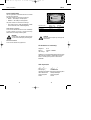
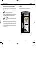
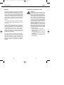
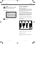
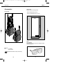
H32-BA PD 10 englisch
8.4.1998 15:22 Uhr
PD 10
Operating Instructions
Seite 1
H32-BA PD 10 englisch
8.4.1998 15:23 Uhr
Seite 2
PD 10
Laser Range Meter
Besides the instructions for use, this
manual also contains important safety information (see “Safety information” section).
Please read the manual carefully
before putting the product into
operation.
Production identification
The type designation and serial number can be found on a
nameplate attached to the rear of the product. Make a note of
this information in your manual and always refer to it when
addressing any queries to our agency or service department.
Type: PD 10
2
Serial no.:
3
H32-BA PD 10 englisch
8.4.1998 15:23 Uhr
Seite 4
PD 10
Symbols
Contents
The symbols used in these operating instructions have the
following meanings:
DANGER
Immediate operating risk leading inevitably to
serious personal injury or death
Safety precautions
. . . . . . . . . . . . . . . . . . . .7
Purpose . . . . . . . . . . . . . . . . . . . . . . . . . . . . .7
Intended use . . . . . . . . . . . . . . . . . . . . . . .7
Examples of misuse . . . . . . . . . . . . . . . . . .7
Operating limits . . . . . . . . . . . . . . . . . . . . . . .8
WARNING
Operating risk or misuse which can lead to
serious personal injury or death
Division of responsibilities . . . . . . . . . . . . . . .9
Operating risks . . . . . . . . . . . . . . . . . . . . . . .10
Laser classification . . . . . . . . . . . . . . . . . . .12
CAUTION
Operating risk or misuse which can lead to only
minor personal injuries, but to serious material, property or environmental damage.
EC declaration of conformity . . . . . . . . . . . .13
Electromagnetic compatibility (EMC) . . . . . .14
Labelling . . . . . . . . . . . . . . . . . . . . . . . . . . . .15
Warranty . . . . . . . . . . . . . . . . . . . . . . . . . . . .16
Information to help the operator use the product in a technically correct and efficient
manner.
FCC statement (applicable in U.S.) . . . . . . . .17
Product information
. . . . . . . . . . . . . . . . . .19
Description of product . . . . . . . . . . . . . . . . .19
Overview of PD 10 . . . . . . . . . . . . . . . . . . . .20
Using the PD 10
. . . . . . . . . . . . . . . . . . . . . .21
Overview of button functions . . . . . . . . . . . .21
Inserting the batteries . . . . . . . . . . . . . . . . .22
Used batteries . . . . . . . . . . . . . . . . . . . . .23
4
5
H32-BA PD 10 englisch
8.4.1998 15:23 Uhr
Seite 6
PD 10
Contents
Measuring . . . . . . . . . . . . . . . . . . . . . . . . . .24
Switching on the device . . . . . . . . . . . . . .24
Range measurement (standard) . . . . . . . .24
Linear measurements with pointer . . . . .26
Continuous measurement (tracking) . . . . .27
Adding / subtracting distances . . . . . . . . .28
Calculation of area and volume . . . . . . . .30
Memorising values for further
calculations . . . . . . . . . . . . . . . . . . . . . . .32
Measuring in inaccessible places . . . . . .34
Measuring on different surfaces . . . . . . .36
Measuring the height of buildings . . . . . .38
Use of collimator marks . . . . . . . . . . . . . .40
Measuring fixed distances . . . . . . . . . . . .41
Measuring with a constant . . . . . . . . . . . .45
Data memory . . . . . . . . . . . . . . . . . . . . . . . .47
Saving data . . . . . . . . . . . . . . . . . . . . . . .47
Erasing the data memory . . . . . . . . . . . . .48
Definition of device parameters . . . . . . . . . .49
Summary of device parameters . . . . . . . .51
Transportation, care and storage
. . . . . . . . .53
Cleaning and drying . . . . . . . . . . . . . . . . . . .53
Storage . . . . . . . . . . . . . . . . . . . . . . . . . . . . .53
Transportation . . . . . . . . . . . . . . . . . . . . . . .53
Safety information
This information is intended to enable PD 10 purchasers and
users to identify any operating risks in time, i.e. to eliminate
them in advance where possible. The customer must make
sure that all users understand and apply these instructions.
Purpose
Intended use
The PD 10 is intended for the following range of applications:
• Measuring distances
• Calculating areas and volumes
• Marking out distances
Examples of misuse
• Use of the product without prior instruction
• Use of the product outside the operating limits
• Rendering safety devices ineffective or removing notices
and warning signs
• Opening the product with tools (screwdriver, etc.) unless
expressly permitted for a particular purpose
• Carrying out conversions or modifications to the product
Error messages . . . . . . . . . . . . . . . . . . . . . . .54
Measuring equipment inspection
Technical data
. . . . .57
. . . . . . . . . . . . . . . . . . . . . . .58
Accessories . . . . . . . . . . . . . . . . . . . . . . . . . .60
6
7
H32-BA PD 10 englisch
8.4.1998 15:23 Uhr
Seite 8
PD 10
Safety information
• Use of accessories by other manufacturers which are not
explicitly approved by Hilti
• Putting a stolen device into operation
• Deliberately dangerous or careless behaviour on
scaffolding, when climbing Iadders or when measuring in
the vicinity of operational machinery or open machine
elements or equipment
• Aiming the device directly at the sun
• Deliberate dazzling of others
WARNING
Misuse may lead to injuries, malfunctions and
damage to property. The customer must inform
the user of the operating risks associated with the
equipment and the corresponding safety
precautions. The PD 10 Laser Range Meter may
only be put into operation subject to prior
instruction of the user.
Operating limits
See “Technical data” section.
Division of responsibilities
Responsibility of the original equipment manufacturer Hilti Corp., FL9494-Schaan (abbreviated to
“Hilti”):
Hilti is responsible for the safe delivery of the product including operating instructions and original accessories.
Responsibility of the external accessory manufacturer
Manufacturers of external accessories for the PD 10 are
responsible for the development, implementation and communication of safety strategies for their products and the
interaction of the latter with the Hilti product.
Responsibility of the customer
WARNING:
The customer is responsible for the proper use of
the equipment, the deployment of his staff, their
instruction and the operational safety of the
equipment.
Environment
Suitable for use in atmospheres which are permanently
habitable by humans. Do not use in corrosive or explosive
environments. The device may be used for limited periods in
rainy conditions.
The customer has the following obligations:
• To ensure that he has understood the safety information
on the product and the instructions contained in the manual
• To be aware of the locally applicable works accident prevention regulations
• To notify Hilti immediately if any safety-related defects
occur in the equipment
8
9
H32-BA PD 10 englisch
8.4.1998 15:23 Uhr
Seite 10
PD 10
Safety information
Operating risks
WARNING
Failure to provide full instruction may lead to
operating errors or misuse, and hence to accidents resulting in serious personal injury or
material, property and environmental damage.
Preventive measures
All users must observe the safety information of the manufacturer.
CAUTION
Beware of measuring errors if using a defective
product or a product which has been dropped or
subjected to any other inadmissible stresses or
changes.
Preventive measures
Carry out check measurements periodically, particularly after
the product has been exposed to excessive strain and before
and after important measuring tasks.
WARNING
Inadequate fencing-off or marking of your measuring site can lead to dangerous situations in
road traffic, building sites, industrial plants, etc.
Preventive measures
Always make sure your measuring site is properly fenced off
and observe the statutory accident prevention regulations and
road traffic regulations of the country in question.
CAUTION:
Inadmissible mechanical influences during the
transportation or disposal of charged batteries
can lead to a fire hazard.
10
Preventive measures
Remove the batteries from the instrument for transportation
purposes and only dispose of them once they are fully
discharged (operate instrument in tracking mode until batteries are used up).
CAUTION
If your equipment is not used for lengthy periods,
there is a risk of it being damaged by leaking
batteries.
Preventive measures
Remove the batteries if you do not intend to use your equipment for some time.
WARNING
Improper disposal of the equipment may lead to
the following:
• Burning of plastic components generates toxic
fumes which can cause illness
• If damaged or exposed to strong heat, batteries may explode, causing poisoning, burns,
acid burns or environmental pollution.
• Careless disposal enables unauthorised individuals to make improper use of the equipment, which may lead to serious injury to yourself or a third party and to pollution of the environment.
Preventive measures
Dispose of the equipment properly, in accordance with the
national waste disposal regulations. Protect the equipment at
all times from access by unauthorised individuals.
11
H32-BA PD 10 englisch
8.4.1998 15:23 Uhr
Seite 12
PD 10
Safety information
Laser classification
The PD 10 generates a visible laser beam which is emitted
from the front of the device.
The product conforms to Laser Class 2 according to:
• IEC825-1: 1993 “Safety of Laser Equipment”
• EN60825-1: 1994 “Safety of Laser Equipment”
The product conforms to Laser Class II according to:
• FDA 21CFR Ch.I §1040: 1988 (US Department of Health
and Human Service, Code of Federal Regulations)
Laser Class 2/ II products
Do not look into the laser beam and do not aim it deliberately
at others. Protection of the eyes is normally ensured by
defence reactions including the blinking reflex.
WARNING
Looking directly into the beam with optical aids
(e.g. binoculars or telescopes) can be dangerous.
Laser exit
aperture
Applicable standard:
IEC825-1: 1993
EN60825-1: 1994
0.16 x 0.8 mrad
1 x 10⁻⁹ s
0.95 mW ±5%
Beam divergence:
Pulse radiation:
Max. power output:
EDA21CFR
Ch. 1 §1040:1988
0.15 x 0.6 mrad
1 X 10⁻⁹ s
0.95 mW ±5%
CAUTION
Only have products repaired by a Hilti-approved
service centre.
Preventive measures
Do not look into the beam using optical aids.
EC declaration of conformity
Designation:
Serial no.:
Year of design:
PD 10
00000000 - 99999999
1997
We declare, on our sole responsibility, that this product complies
with the following standards or standardisation documents:
IEC 801-2 according to the provisions of the directives
89/336/EEC.
Hilti Corporation
Armin Spiegel
Leiter Positioning Systems
Head of Business Unit
Positioning Systems
09/1997
12
Dr. Heinz Kousek
Entwicklung Positioning Systems
Development Manager
Positioning Systems
09/1997
13
H32-BA PD 10 englisch
8.4.1998 15:23 Uhr
Seite 14
PD 10
Safety information
Electromagnetic compatibility (EMC)
Labelling
Electromagnetic compatibility refers to the ability of the PD
10 to function properly in an environment with electromagnetic radiation and electrostatic discharge without inducing
electromagnetic faults in other devices.
All product identification data and warnings regarding the use
of the product can be found on the rear of the PD 10.
WARNING
Possibility of interference with other equipment
due to electromagnetic radiation.
Although the PD 10 complies with the strict requirements of
the relevant directives and standards, Hilti cannot entirely rule
out the possibility of interference with other equipment.
AVOID EXPOSURE
Laser radiation is emitted
from this aperture
C A U T I O N
LASER RADIATION - DO NOT
STARE INTO BEAM
CAUTION
Measurements may exceed tolerances in the
event of interference caused by electromagnetic
radiation.
620-690nm/0.95mW max.
CLASS II LASER PRODUCT
This laser Product complies
with 21CFR 1040 as applicable
2
1/4s
Although the PD 10 complies with the strict requirements of
the relevant directives and standards, Hilti cannot entirely rule
out the possibility of the PD 10 being interfered with by highly
intensive electromagnetic radiation; e.g. in the direct vicinity
of radio transmitters, transmitter-receivers, diesel generators,
etc.
Always check readings for plausibility when measuring under
these conditions.
with part 15 of
This device complies
the FCC Rules.
Operation is subject
two conditions:
to the following
(1) This device may not cause harmful
interference, and (2) this device must
accept anyinterference received,
including
interference thatcause
may
undesired operation.
Æ
Hilti = registered trademark of the
Hilti Corporation, FL-9494 Schaan
Type: PD
10
Item No.:
310015
Power:6V
nominal
200mA
S. No.:1234567
Manufact.:
12/1997
310017
Made in Switzerland
14
15
H32-BA PD 10 englisch
8.4.1998 15:23 Uhr
Seite 16
PD 10
Safety information
Warranty
FCC statement (applicable in U.S.)
Hilti warrants the supplied device to be free from defective
materials and workmanship. This warranty is only valid on
condition that the device is operated, handled, cleaned and
cared for correctly according to the operating instructions
provided by Hilti, that all warranty claims are asserted within
12 months of the date of sale (date of invoice) and that
technical integrity is guaranteed, i.e. that only original Hilti
expendable items, accessories and spare parts are used with
the device.
This warranty covers free repairs or replacement of defective
parts. It does not apply to parts which are subject to normal
wear and tear.
All further claims are excluded failing the existence of
mandatory national regulations to the contrary. In particular,
Hilti accepts no liability for direct or indirect deficiency losses
or consequential damage, losses or costs incurred in
connection with the use of, or due to the impossibility of
using the device for any purpose. Implicit warranties of the
applicability or suitability of the device for a particular
purpose are expressly excluded.
For purposes of repair or replacement, the device and/or
affected parts must be sent to the responsible Hilti marketing
organisation immediately on discovery of the defect. The
present warranty covers all guarantee commitments on the
part of Hilti and replaces any earlier or simultaneous
declarations, written or oral agreements with regard to
warranties.
16
WARNING:
This equipment has been tested and found to
comply with the limits for a Class B digital
device, pursuant to part 15 of the FCC Rules.
These limits are designed to provide reasonable
protection against harmful interference in a residential installation. This equipment generates,
uses and can radiate radio frequency energy and,
if not installed and used in accordance with the
instructions, may cause harmful interference to
radio communications. However, there is no
guarantee that interference will not occur in a
particular installation. If this equipment does
cause harmful interference to radio or television
reception, which can be determined by turning
the equipment off and on, the user is encouraged
to try to correct the interference by one or more of
the following measures:
• Reorient or relocate the receiving antenna.
• Increase the separation between the equipment and receiver.
• Connect the equipment into an outlet on a
circuit different from that to which the receiver
is connected.
• Consult the dealer or an experienced radio/TV
technician for help.
17
H32-BA PD 10 englisch
8.4.1998 15:23 Uhr
Seite 18
PD 10
Safety information
WARNING:
Changes or modifications not expressly
approved by Hilti for compliance could void the
user’s authority to operate the equipment.
Product information
Description of product
The PD 10 is a range meter which employs a laser beam to
measure distances within the 0.3m - 100 m range with great
precision and without physical contact. It is a hand-held tool
and can be operated quickly by one person.
Product labeling
This device complies with part 15 of the FCC
Rules. Operation is subject to the following
two conditions:
(1) This device may not cause harmful
interference, and (2) this device must accept
any interference received, including
interference that may cause undesired
operation.
See section “Labels” in the chapter “Safety precautions”.
The range of the tool depends on the reflectance and surface
finish of the point to be measured. With the types of surface
usually encountered in the field of construction, it is possible
to measure distances of 0.3 - 30 m. A target plate with a
reflective surface can be used for distances up to 100 m.
The point being measured is clearly identified by the red spot.
The reference point on the tool can be selected for different
types of measurements.
Possible reference points are:
a
b
c
d
a) the rear edge of the instrument (standard setting)
b) the internally threaded bushing (1/4”) for mounting the
tripod
c) the front edge beside the lens
d) the end of the pointer (e.g. for measurements taken from a
corner)
18
19
H32-BA PD 10 englisch
8.4.1998 15:23 Uhr
Seite 20
PD 10
Productinformation
Using the PD 10
Overview of PD 10
Overview of button functions
T
SE
PC
T
DA
M+
N
ME
M-
ON FF
O
L
RC
R
CL
6
8
7
5
R
CL
3
N
ME
M-
ON FF
O
L
RC
1
SE
T
PC
T
DA
M+
Measuring and memory buttons
ON-OFF
Measure
Memorise - add
Memorise - subtract
2
4
5
Display last stored value
Delete entire memory contents
1 Laser exit aperture
2 Receiving lens
3 Display
4 Control panel
5 Tripod mount
6 Mounting plate
7 Removable module with battery holder
8 Pointer
Calculation buttons
Addition button
Multiplication button
Subtraction button
Total button
Special functions
Menu button
Button for memorising values
PC link (not yet implemented)
Setting of fixed distances
20
21
H32-BA PD 10 englisch
8.4.1998 15:23 Uhr
Seite 22
PD 10
Using the PD10
Inserting the batteries
Used batteries
This battery symbol appears in the display when the batteries
are discharged or if the battery voltage is too low:
Always replace the complete set of batteries !
Press in the clips at the side of the removable module and
remove. Open the hinged cover and take the battery holder
out of the removable module.
Please note:
• Do not mix old and new batteries.
• Do not use batteries of different makes or
types.
• See technical data for the type of battery to
use.
Insert batteries in the battery holder, taking care to observe
the correct poles (according to labelling).
Re-insert battery holder in the removable module as shown
in the diagram.
Slide the removable module back into the device with the
contact pins pointing upwards.
22
23
H32-BA PD 10 englisch
8.4.1998 15:23 Uhr
Seite 24
PD 10
Using the PD10
Measuring
The following instructions refer to the standard
basic settings of the PD 10 (see section
“Definition of device parameters”).
Switching on the device
Switch on device.
If the acoustic signal is switched on, a beep tone
will sound.
The current reference point (rear edge of tool)
appears in the display together with the reading
“0.000”.
Press the “Measure” button.
The display indicates that the laser is switched
on.
Once the device is switched on, the reference
point remains permanently set to “rear edge of
tool” (symbol).
Changing the reference point
By pressing the two buttons “DAT” and “MEN”
simultaneously, you can switch rapidly between
the reference point “rear edge of tool” (symbol)
and “front edge of tool” (symbol). For other
possible settings, see the section ‘’Definition of
device parameters”.
Range measurement (standard)
Place the rear edge of the tool at the desired
starting point and align it with the opposite target
point.
24
If the measuring button is not pressed again
within 20 seconds, the laser switches off
automatically.
Press the “Measure” button again.
The display indicates that the measurement is in
progress.
On completion of the measurement, a beep tone
sounds and the laser is extinguished. The measured value (e.g. “ 1 .234m”) appears in the display.
25
H32-BA PD 10 englisch
8.4.1998 15:23 Uhr
Seite 26
PD 10
Using the PD10
Linear measurements with pointer
Continuous measurement (tracking)
T
SE
Press the “Measure” button.
PC
T
DA
The display indicates that the laser is switched
on.
M+
N
ME
M-
ON FF
O
L
RC
R
CL
If the measuring button is not pressed again within 20 seconds, the laser switches off
automatically.
> = 0,8s
Press the “Measure” button again and hold down
for at least 0.8 seconds.
The display indicates that the tool is in tracking
mode.
In order to measure on the diagonal or from otherwise inaccessible corners, the pointer can be extended. The instrument
takes into account the extended reference point and automatically corrects the measured distance accordingly.
The measuring process takes place as described under the
section “Linear measurements (standard)”.
26
It is now possible to read off the current distance
at any time as the tool constantly changes
position.
The tracking mode can be deactivated at any
time by pressing any button.
27
H32-BA PD 10 englisch
8.4.1998 15:23 Uhr
Seite 28
PD 10
Using the PD10
Adding/subtracting distances
Individual distances can be easily added or subtracted.
Press the “Measure” button.
The laser is switched on.
The following example shows how to add two partial heights
to be measured at a wall.
For the first partial height, position the PD 10
with the rear edge mark at the top.
1,155m
Press the “Measure” button again.
1,105m
2,260m
The first partial height is measured and displayed
(laser is switched off).
Press the “Plus” button.
Press the “Measure” button.
The laser is switched on.
For the second partial height, position the PD 10
with the rear edge mark at the bottom.
Press the “Measure” button again.
The second partial height is measured and displayed (laser is switched off).
Press the “Total” button.
The sum of both partial heights can now be read
off from the display.
1/4´´
28
29
H32-BA PD 10 englisch
8.4.1998 15:23 Uhr
Seite 30
PD 10
Using the PD10
Calculation of area and volume
Finally, press the “Total” button. The display
shows the calculated floor area: 29.313 m2.
Example:
Determining the floor area of a room
Measure the width of the room.
Determining the volume of a room
Determine the floor area of the room as described
above. Then place the PD 10 on the floor.
Press the “Multiplication” button.
A small square flashes in the display.
3,5m
Measure the height of the room, e.g. 2.285 m.
2.285m
The display shows the measured width, e.g.
3.5m.
Press the “Multiplication” button.
A small square flashes in the display.
Measure the length of the room.
Finally, press the “Total” button. The display
shows the calculated volume, e.g. 66.980 m3.
8,375m
The display shows the measured length, e.g.
8.375 m.
30
31
H32-BA PD 10 englisch
8.4.1998 15:23 Uhr
Seite 32
PD 10
Using the PD10
Memorising values for further calculations
After appearing in the display, individual measurements, area
calculations or volume calculations can be transferred to the
memory for use in further calculations.
The following values can be transferred to the memory (added
or subtracted) using buttons
and
• individual or cumulative distances (m)
• areas (m2)
• volumes (m3)
Transfer the floor area value for room 1 to the
memory using the “M+” button.
The display shows the memorised floor area
value for room 1 together with the letter “M” for
“memory”.
Determine the area of room 2 (same procedure
as for room 1).
Mixed values (e.g. distances and areas or
volumes) cannot be combined. In such cases, the
error code E 103 appears in the display and a
beep tone sounds.
The display shows the floor area value for room
2, e.g. 28.840m2.
Example:
Addition of two areas
Press the “M+” button again.
Measure the length of room 1.
When the distance appears in the display, press
the “Multiplication” button.
A small square flashes in the display.
The result of the addition of floor areas 1 and 2
appears in the display.
Other areas can be added or subtracted in the
same way.
To display the last memorised value
Measure the width of room 1.
When the distance appears in the display, press
the “Total” button.
The display shows the calculated floor area for
room 1: e.g. 23.534m2.
32
Press the “RCL” button.
To delete the memory contents
Press the “CLR” and “RCL” buttons
simultaneously.
33
H32-BA PD 10 englisch
8.4.1998 15:24 Uhr
Seite 34
PD 10
Using the PD10
Measuring in inacessible places
In order to reach measuring points with the PD 10 which are
otherwise completely or partially inaccessible, the use of an
extension rod is recommended.
The extension rod can be mounted on one of the three internally threaded bushings (1/4” standard camera tripod thread)
on the PD 10.
Setting the timed release
Switch on the device.
Press the menu button.
Switch to the device parameter “dLY...” via the
“M+” button.
Use the “+” and “-” buttons to enter the desired
delay in seconds, e.g. 5 sec.
Press the menu button again.
Attach the extension rod to the PD 10.
Press the measuring button. The laser is
switched on.
Press the measuring button again. The following
appears in the display:
The delay time elapses.
If using an extension rod, you will need to delay the activation of the measurement accordingly after pressing the measuring button. This delay can be adjusted via the device parameter “dLY...” (measuring delay).
During the set delay time, position the measuring
tool at the measuring point and align it so that it
is as perpendicular as possible to the target
point.
Once the delay time “dLY” (5 sec.) has elapsed,
the measurement is performed and the beep tone
sounds.
The display shows the measured value, e.g.:
34
35
H32-BA PD 10 englisch
8.4.1998 15:24 Uhr
Seite 36
PD 10
Using the PD10
Measuring on different surfaces
To avoid measuring in plaster seams: Use a target plate, 3M
“Post-It” stickers or a sheet of cardboard.
Plants and trees
As a rule, it is not possible to measure on plants and trees,
even over very short distances. The range of the PD 10 becomes shorter on mat green surfaces.
Wet, smooth or gloss-painted surfaces
1. When sighting at a flat angle, the laser beam is deflected
according to the laws of optics. As a result, the PD 10 may
receive too weak a signal. In this case, the message “LO
SIG” appears in the display.
Rough surfaces
On rough surfaces (e.g. coarse plaster), a weighted average
measurement is obtained, whereby the centre of the laser
beam has a higher weighting than the marginal area.
If the differences are too great, a corresponding message
appears in the display.
36
2. When sighting at a right angle, the PD 10 may receive too
strong a signal. In this case, the message “HI SIG”
appears in the display.
Transparent surfaces
CAUTION
In order to avoid optical errors in the measuring
tool, do not measure against transparent surfaces
(e.g. water or glass).
37
H32-BA PD 10 englisch
8.4.1998 15:24 Uhr
Seite 38
PD 10
Using the PD10
Measuring the height of buildings
Calculation example for height h:
The PD 10 can be used to measure at very flat angles, e.g. in
order to determine the height of building facades.
Given quantities:
Required quantity:
The indicated distance corresponds to the distance from the
rear end of the pointer to the centre of the extended beam
impact point of the laser.
Height h=
In the case of gloss-painted metal sheets, the message “HI
SIG” may appear in the display. In this case, you should
conduct the measurement in the evening or wait until the
target point is no longer within the range of direct sunlight.
38
distance a, slant range a
height h
10.049m x 10.049m - 0.995m x 0.995m
= 100.9824m2 - O.9900m2
= 99.9924m2 (extract root A)
= 9.9996m
The height h is now established.
39
H32-BA PD 10 englisch
8.4.1998 15:24 Uhr
Seite 40
PD 10
Using the PD10
Use of collimator marks
Measuring fixed distances
To measure distances on outer edges (e.g. outside walls of
houses, fencing, etc.), you can place aids such as boards,
bricks or other suitable objects on the outer edge as
collimator marks.
Fixed distance Pl
The function “measure fixed distances” is very useful when
positioning several marks or fastenings from a fixed point.
For this purpose, enter a fixed distance value Pl. Then direct
the PD 10 from the starting point towards a mobile target (e.g.
hand, target plate, marker pen, etc.).
P1
To check the distance, a beep tone is emitted at different
sound pulse frequencies. The closer the target is moved to the
set distance value Pl, the more rapid the sequence of beeps
becomes.
At the same time, the positive or negative difference separating the target point from the set distance value Pl appears
continuously in the display. When the value “0.000” is reached, the target distance coincides with the precept value Pl.
40
41
H32-BA PD 10 englisch
8.4.1998 15:24 Uhr
Seite 42
PD 10
Using the PD10
Entering the distance value Pl
Switch on the PD 10.
Fixed distance Pl with distance interval P2
The same function can be used in order to split a distance
with the initial value Pl into subsequent equal distance intervals (P2).
Press the “SET” button.
In the display, the message “Pl” flashes together
with a pencil symbol and the value “0.000” or the
last value to have been entered.
P2
Enter the desired distance value using the
“+”/”-” buttons.
P2
Press the total button.
In the display, the message “P2” flashes together
with a pencil symbol and the value “0.000” or the
last value to have been entered.
P2
P1
Enter the value “0.000” for “P2”.
Press the total button again.
Entering the distance value Pl
Switch on the PD 10.
Then press the measuring button to switch on the
laser. The messages “Laser” and “Pl setout”
appear successively in the display, which then
switches to the measuring mode.
Press the “SET” button.
In the display, the message “Pl “ flashes together
with a pencil symbol and the value “0.000” or the
last value to have been entered.
N
Enter the desired initial distance value, e.g.
“0.500”, using the “+”/”-” buttons.
Move the target point (target plate or similar
object) into the laser beam and align according to
the pre-set distance, using the sequence of beeps
as a guide. Mark the target point.
42
43
H32-BA PD 10 englisch
8.4.1998 15:24 Uhr
Seite 44
PD 10
Using the PD10
Press the total button.
Measuring with a constant
In the display, the message “P2” flashes together
with a pencil symbol and the value “0.000” or the
last value to have been entered.
It is also possible to obtain measurements by entering a fixed
constant.
Enter the value for the interval distance “P2”, e.g.
“0.625”.
Example:
Several rooms in the carcass of a building are to be fitted with
a floor covering to a height of 8 cm. On the basis of this
specified floor covering height, you wish to determine how
many cubic metres of floor covering material are required for
all the rooms.
Determine the floor area for each individual
room.
Press the total button again.
Then press the measuring button.
The laser is switched on, and the messages
“Laser” and “Setout” appear successively in the
display, which then switches to the measuring
mode.
See the section “Calculation of area and volume”
for area calculations.
Add the resulting individual areas using the “M+”
button.
Press the menu button.
Recall the “ConSt” parameter using the “M+”
button.
N
Enter the value “0.080” using the “+”/”-” buttons.
Move the target point (target plate or similar
object) into the laser beam and align according to
the first initial target point Pl, using the sequence
of beeps as a guide. The target point can now be
moved back as often as necessary by the next P2
interval distance of 0.625m. When the correct
interval distance is reached, the sequence of
beeps becomes accordingly faster. In this way, it
is possible to mark the individual distance
sections.
44
Confirm your input with the total button.
Press the multiplication button.
A small square will flash in the display.
45
H32-BA PD 10 englisch
8.4.1998 15:24 Uhr
Seite 46
PD 10
Using the PD10
Press the “RCL” button to recall the previously
memorised total area value.
Then press the total button once again.
The display now shows the calculated volume
for the required floor covering material in “m”.
Data memory
In the “Data memory” mode, you can store up to 100 readings
(storage locations 00 to 99). The “Data memory” mode is
obtained by pressing the appropriate button.
You can cancel this mode at any time without losing the
stored data by pressing the button again.
Saving data
Open the data memory.
The number of the first vacant memory location
flashes in the display.
After a measurement or calculated result, save the
displayed value with the “Total” button.
The assigned storage locations can be recalled
via the “M+” and “M-” buttons.
If you attempt to save the value in an already
occupied storage location, the number of that
location appears in the display accompanied by
the message “Full”. The value is not saved.
46
47
H32-BA PD 10 englisch
8.4.1998 15:24 Uhr
Seite 48
PD 10
Using the PD10
The “CLR” button can be used to delete the relevant storage location and then save a new value.
When all 100 storage locations are assigned, you
are notified accordingly via the message “Full” in
the display.
Erasing the data memory
In order to erase the entire data memory, press
the two buttons “DAT” and “CRL” simultaneously. You are asked to confirm this action in order
to protect the data against accidental deletion.
Definition of device parameters
Before you begin measuring, make sure that the PD 10 is preset to the correct device parameters.
The following device parameters can be checked or set in the
menu mode.
• Reference point [“rEF”]
Graphic display of reference point on the PD 10 for
measuring distances
Possible selection:
- front edge of tool (symbol)
- centre of tool (tripod thread) (symbol)
- rear edge of tool
(= standard setting) (symbol)
The message “Sure?” appears in the display. To
confirm the deletion, press both keys again. All
assigned storage locations are then deleted and
the display returns to the first storage location
with the number 00.
By pressing the buttons
and
simultaneously, you can switch rapidly between
the reference points “rear edge of tool” and “front
edge of tool”.
• Constant [“ConSt”]
The constant can be used for calculations. Only one
constant may be used for each calculation. Setting range:
0.001- 9.999
The input is acknowledged with the “=” button.
• Recall of last four displayed values. No inputs possible!
• Measurement delay [“dLY”]
Interval (in seconds) between pressing of measuring
button and initiation of measurement.
Setting range: 0.0 to 9.9
Standard setting: “0.3”
48
49
H32-BA PD 10 englisch
8.4.1998 15:24 Uhr
Seite 50
PD 10
Using the PD10
• Unit of measure [“m”/”in” (ft)”]
Selection of metres or inches (feet) as the unit of measure.
Standard setting: “m”
• Laser on/off [“LA On/OFF”]
On/off selection for continuous laser beam operation.
Laser on: Once activated, the laser beam is illuminated
permanently, thus allowing measurements to be conducted continuously. Laser off (= standard setting): The laser
beam has to be re-activated before each measurement,
and switches off again after each measurement.
Summary of device parameters
ON
OFF
MEN
M+
• Beep tone on/off [“bP On/OFF”]
On/off selection for beep tone
By pressing the buttons
and
M+
simultaneously, you can switch rapidly between
beep tone ON and OFF.
• Back-lit display [“LI On/OFF”]
On/off selection for back-lit display
By pressing the buttons
M+
and
simultaneously, you can switch rapidly between
backlighting ON and OFF.
M+
See next page for a summary of the available
parameters.
M+
M+
M+
50
51
H32-BA PD 10 englisch
8.4.1998 15:24 Uhr
Seite 52
PD 10
Using the PD10
Explanation of button functions
Switch on the device.
Transportation, care and
storage
Press the menu button.
First parameters appear in the display.
Cleaning and drying
• Blow dust away from the lenses
• Do not touch the glass with your fingers
The menu mode is deactivated either by pressing
the menu button again or automatically if no
button is pressed for 30 seconds.
• Only use clean, soft cloths for cleaning; if necessary,
moisten slightly with pure alcohol.
Do not use any other liquids, as these may
damage the plastic components.
The buttons “+”/”-” can be used to change the
current value or choose between the possible
settings. To change numeric values:
- Pressing the “+”/”-” button briefly causes the
displayed numeric value to be increased/
decreased by “0.001” of the smallest indicating
unit.
- Keeping the “+”/”-” button pressed causes the
displayed value to be increased/decreased at a
faster rate.
- Pressing the “x” and “+” or “-” buttons simultaneously causes the displayed value to be
increased/decreased in steps of “0.100”.
Pressing the M+/M- buttons: Saves the displayed value and then switches to the next or
previous parameter.
Pressing the “MEN” button: Saves the currently
selected parameter settings, then exits the menu
mode and returns to the standard measuring
mode.
52
Observe the temperature limits when storing your
equipment, particularly in summer if kept inside
a vehicle (-40°C to +70C / -40°F to +158°F).
Storage
If equipment gets wet, unpack and dry the tool,
transport container, foam insert and accessories
(at a maximum temperature of 40°C /108°F). Do
not put your equipment back into its packaging
until it is completely dry.
After lengthy storage or transportation periods,
your equipment should undergo a check measurement before use.
Transportation
Your equipment should be transported in the Hilti mailing
carton or packaging of similar quality. Always transport the
tool without batteries.
53
H32-BA PD 10 englisch
8.4.1998 15:24 Uhr
Seite 54
PD 10
Error messages
Error messages
Optical errors during measurements, unacceptable user
inputs or faults in the tool are indicated in the display by
means of an error code.
When an error message appears, switch the tool
on and off several times to check whether it
occurs repeatedly before contacting your service
centre.
The following list shows the possible error codes, their
meanings and the type of corrective action required in order
to eliminate them:
Code
Meaning
E103
Illegal command input.
Invalid result.
E124-E199 General hardware error
Corrective measure:
Notify service centre.
E203
Corrective measure:
New measurement/new input
E217-E224 General hardware error
Corrective measure:
Notify service centre.
E252
No communication with module, possibly after
dropping the tool. Distance measurement not
possible.
E253
E272-E299 defective measuring module, back to service.
LO SIG
Parameter setup not OK
HI SIG
Parity error
Corrective measure:
Repeat measurement; notify service centre if
message persists.
54
Receiving signal too low, too much ambient
light
Corrective measure:
- Observe measuring distance (> 300mm)
- Clean lens
- Measure against a different surface (target
plate)
Corrective measure:
Notify service centre.
E 121
Temperature too low (> -10°C)
Corrective measure:
Warm tool.
Corrective measure:
Notify service centre if message persists.
E 117
Temperature too high (> +50°C) in tracking
mode and in setting-out mode (3 +45°C)
Corrective measure:
Allow tool to cool down.
Corrective measure:
New measurement/new input
E 106
Illegal command input.
Receiving signal too high
Corrective measure:
- Measure against a different surface (target
plate)
55
H32-BA PD 10 englisch
8.4.1998 15:24 Uhr
Seite 56
PD 10
Error messages
FULL
Memory full (DAT mode)
Corrective measure:
Erase entire memory or unwanted storage locations
no SIG Measurement takes longer than 20 seconds in setting-out or tracking mode
Corrective measure:
See “LO SIG”
bright
Target point subjected to excessively bright ambient
light
Corrective measure:
Shade target point
Measuring equipment
inspection
Measuring equipment inspection of PD 10 for users
who are certified according to ISO 9000:
You can carry out the measuring equipment inspection
required by ISO 9000 on the linear measuring device PD 10
yourself.
For this purpose, select a measuring distance which remains
constant over time and which is easily accessible, with a
known length of approx. 1 to 5 m (e.g. window opening, room
width) and carry out 10 measurements.
Determine the deviation of the readings from the nominal
measuring distance and calculate the standard deviation on
this basis.
Make a note of this value and fix a time for the next inspection.
Repeat this check measurement at regular intervals and before
and after important measuring tasks.
Apply a measuring equipment inspection sticker to the PD 10
and document the entire inspection procedure.
Your PD 10 conforms to the specified accuracy level if the
standard deviation remains less than or equal to 6 mm.
A PD 10 which has been inspected over the test distance
operates with the accuracy specified in the manual over the
entire specified length and temperature range. Please refer to
the technical data contained in the manual, together with the
explanation of accuracy levels.
56
57
H32-BA PD 10 englisch
8.4.1998 15:24 Uhr
Seite 58
PD 10
Technical data
Technical data
Tool data
Performance data
Light source
Laser diode 620 - 650 mm,
power output < lmW
Measuring range
• 0.3 to 30 m
(on natural construction surfaces with
“albedo” > 0.2)
• 20 to 100 m with target plate
(“albedo” > 0.5)
Laser class
see page 12
Dimensions
212x82x50mm
(8.3” x 3.2” x 2”)
Accuracy
± 3 mm individual measurement @ 23°C
± 5 mm from 0°C to +50°C
± 7 mm from -10°C to +50°C
Beam diameter
< 6 mm @ 10 m
< 30 mm @ 50 m
< 60 mm @ 100 m
Operating modes
• Individual measurements
• Continuous measurement
• Pre-set distance
• Calculation
• Data memory
Operating status indicator
Liquid crystal display indicating individual
operating modes and operating status
Weight
600 g
Power supply
Type:
Standard:
Optional:
AA (LR6, AM3, round cell R6)
4 primary cells, alkaline
NiCd rechargeable
Battery life at 25°C
Alkaline: 2000 measurements lasting 5 sec.
Battery condition
Warning appears in display when battery voltage
is low
Operating temperature
-10°C to +50°C (14°F to 122°F)
Storage temperature
-30°C to +60°C (-22°F to 140°F)
Protection class
Dust and splash-proof
IP 54 as per IEC 529 standard
Mounting points
1/4” Whitworth internal thread
(standard camera tripod thread)
58
59
H32-BA PD 10 englisch
8.4.1998 15:24 Uhr
Seite 60
PD 10
Accessories
Accessories
Target plates
With two different coloured target areas:
Carrying bag
- white, for measurements up to 30 m
- brown, for measurements from 30 to 100 m
SET
PC
M+
M-
T
DA
L
RC
N
ME
CLR
200 mm
ON
OFF
PA 410
75 mm
Option
Target glasses
The target glasses serve to improve the visibility of the laser
target point (factor 4-5).
Batteries
Four
1.5 V batteries
type AA, alkaline
Replacement batteries can be purchased locally.
60
61
H32-BA PD 10 englisch
8.4.1998 15:24 Uhr
Seite 62
PD 10
Notes
Notes
62
63
8.4.1998 15:24 Uhr
Hilti® = Registered trademark of Hilti Corp., Schaan
Right of technical and programme changes reserved
W2154 0298 10 engl. 9
Printed in Liechtenstein © 1998 S.E.&O.
312357/C
H32-BA PD 10 englisch
Seite 64
Dear PD10 Customer
The PD10 Laser Range Meter you have purchased
is factory set for measuring in the metric system. If
you would like to change to imperial measurements
(feet and inches) please follow the instructions:
1 Insert the 4 batteries (they can be found in the
side pocket of your canvas pouch)
2 Press
(ON/OFF)
1×
3 Press
(MEN)
1×
4 Press (M+)
4× until
4×
«UNIT m» is shown
5 Press (+)
1×
6 Press (MEN)
again to leave
the menue
1×
This setting is now effective and will not change if
the unit is switches off or if batteries are changed.
To change back to metric measurement please
refer to the user manual pages 51 and 52.
®
314362/5
Chères Clientes, Chers Clients
Le lasermètre PD10 que vous venez d’acheter, a
été réglé en usine pour pouvoir effectuer des
mesures dans le système métrique. Si vous voulez
effectuer des mesures avec les unités pieds et
pouces, veuillez suivre les instructions suivantes:
1 Insérer les 4 piles (vous les trouverez dans la
poche latérale de votre étui-ceinture en toile)
2 Appuyer sur
(ON/OFF)
1×
3 Appuyer sur
(MEN)
1×
4 Appuyer 4 fois
sur (M+) jusqu’à
«UNIT m»
4×
5 Appuyer sur (+)
1×
6 Appuyer de nouveau 1×
sur (MEN)
pour quitter
le menu
Le réglage est maintenant terminé. Votre appareil
ne devrait plus changer d’unité lorsque vous
l’éteindrez ou changerez les piles. Pour revenir au
système métrique, vous reporter aux pages 51 et
52 du mode d’emploi de l’appareil.
®
314362/5