1
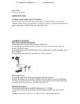
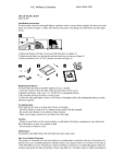
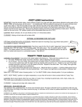
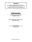
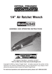
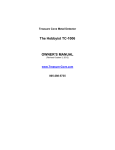
SAVE THESE INSTRUCTIONS AND READ ALL INSTRUCTIONS
14. For supply connections use No. 14 AWG or larger wires suitable for at least 90 "c (194 "F ).
BEFORE USING THE HEATER.
15. For overheat protection, exhausting automatically turns on when temperature above the
ceiling exceeds 90 "C (1941' ).
Preface
Dear customers,
Thank you for selecting AUPU , which is surely to bring you satisfaction. Read all instructions
before using the heater.
WARNINGI
TO REDUCE THE RISK OF FIRE, ELECTRIC SHOCK, OR INJURY TO
PERSONS, OBSERVE THE FOLLOWING:
16. The lamps are hot when in use. It is absolutely prohibited to touch the infrared lamps with
any part of your body when in use.
17. Shut off power urgently when any abnormalities occur in operation. Then call your local
licensed electrician for inspection or necessary service work.
18. Children , elders and 1 or handicapped should use this product under family guidance.
19. Do not use out doors.
20.To reduce risk of fire, use only type RF lamps 270 watts maximun. Replace bulb with 60
watts type A bulb only. It may affect operation (even cause danger) when use lamps other than
the designated one.
CAUTION
1. Use this heater only as described in this manual. Any other use not recommended by the
manufacturer may cause fire, electric shock, or injury to persons . If you have questions, contact
the manufacture or local agent.
2. Make sure the power is off during the installation. Shut off power before servicing or cleaning.
3.lnstallation work and electrical wiring must be done by a qualified person(s) in accordance with
all applicable codes and standards.
4. For the purpose of avoiding any dangerous gas leaking into your bathroom , the duct must not
be laid together with the vent-pipe of air-fueled water heater into the same flue.
5. To prevent a possible fire, do not block air intakes or exhaust in any manner.
6. Do not insert or allow foreign objects to enter any ventilation or exhaust opening as this may
cause an electric shock or fire, or damage the heat.
1. For general ventilating use only. Do not use to exhaust hazardous or explosive materials and
vapors.
2. This product is designed for installation in flat ceilings only. Do not mount it on a sloping
ceiling or a vertical wall.
3. To avoid motor bearing damage and noisy and/or unbalanced impellers, keep drywall spray,
construction dust, etc. off the unit.
4. It is highly recommended to make preparation for heater installation when you retrofit your
bathroom.
5. Please read specification label on product for further information and requirements.
7. A heater has hot and arcing or sparking parts inside. Do not use it in area where gasoline,
paint, or flammable liquids are used or stored .
8. The heater must not be installed at a place that suffers from severe water leakage.
INSTALLATION
9. Do not install closer than 10 inches to a vertical surface and 6 feet to the ground.
10. The heater must not be installed beneath a fixed socket.
11. When cutting into the wall , do not damage electrical wiring and other hidden utilities.
12.The unit has been tested to be in contact with insulation (Type IC).
13.The heater must be properly grounded.
R.E. Williams Contractor Inc.
1
PREPARATION FOR INSTALLATION
1. Cutting a vent (Figure1)
Locate a vent position (above the ceiling) on the wall , and then cut a 4 1/8 inches diameter hole
at the very position .
www.rewci.com
2
2.Ducting
Put one end of the 4 inches diameter
ventiduct into the vent hole. Insulate and
seal space around the hole.
Note: Since the length of the duct is 5
feet, make sure that from the center
of installation position there should
be a distance within 5 feet to the vent.
If it requires more than 5 feet of
distance, purchase an extension
ventiduct from your local agent.
a) Position housing between joists and extend mounting brackets. Position brackets so that
bottom edge of housing will be flush with suspended ceiling . Mark the top of keyhole on all four
mounting brackets (Figure4).
cutting $ 4 118 inches hole
b) Remove housing temporarily and pound nails partially into joists at all four marked locations
(Figure5).
c) Hang housing to nails. Pound nails tight.
Note: To ensure a noise-free mount, crimp the bracket channels tightly around mounting
brackets.
Figure 1
3. Locating the heater
For the purpose of obtaining best heating effect, from the lamps there should be a 7 feet- 8 feet
overall height to ground.
Note: The ceiling joists must be strong.
Figure4
FigureS
4. Remove the fascia
Remove all lamps from the heater. Unclip four fascia-retaining springs inside the housing.
Remove the fascia.
3. Fit the in-house end of the duct to the fan outlet of the housing (Figure6).
Keep the duct as straight as possible.
Note: Do not force when removing the infrared lamps.
5. Take out three screws from the wire cover and remove the wire cover.(Figure2)
ventiduct
WIRING
6. Remove one of the knockouts according to the need.
1. Put one end of the interconnecting
wire through the opened knockout.
7. Fix a clamp connector or wire holder to the opened
knockout.
Figure 2
2. Make wire connections with the
terminal block as figure7.
- UflWm
.... ..
INSTALLATION
~
housi
1. Slide adjustable mounting brackets into bracket
channels on housing (Figure 3).
mou n~ ng
bracket
Note: Make sure that connections are
used to hold wires firmly in place.
3. Connect the other end of
interconnecting wire with the switch
panel (Figure7).
_
K
Note:Try to keep the redundant wire
away from the housing.
Final Installation
L
12QV - 60Hz
= GOO
Figure 7
1. Replace the wire cover to the housing.
2. Fix the brackets
R.E. Williams Contractor Inc.
I
>----- " - ,
K:Breaker H:Heal R:Ughl F:Exhausl
IN:Ughting lamp IR:lnfrared lamp
9:Heal prolector
Figure 3
3
Figure6
www.rewci.com
4
2. Replace the fascia.
2) Shut off power before replacement.
3. Replace the lamps.
Ensure the lamps are screwed sufficiently to make good electrical contact. Clean the globes
and fascia.
3) Use a 120V, maximum 60W type A bulb only for lighting.
4) Use our designed 120V, 270W infrared heat lamps.
CiBJ
WARRANTY
Our bathroom master uses the infrared lamps as a source of heat. It also combines the
functions of exhausting and lighting.
The product is warranted against parts failure for a period of three years. Labor costs extra.
1. Heating
Please contact your local agencies for warranty services.
2 lamps: Turn on/off' ¢- # 1 ' or P. #2 button.
4 lamps: Tum on/off' P. # 1 ' and' -¢: #2 'button.
This model is supplied with 2 groups of infrared lamps. You can turn on one or both of them
for best heating effect.
I
I
This warranty does not cover damage or loss caused by:
a. Light lamp.
b. Any consequential losses arising from incorrect installation or operation or maintenance of
this product.
2. Exhausting
h '
Tum on/off'
button.
The heater can exhaust damp and steam in a quick and efficient way by turning on the ' ~ ,
button. No additional exhaust fan is necessary for the heater itself satisfies your need in
exhausting in bathroom.
3. Lighting
Tum on/off'
Q
'button.
c. Any consequential losses arising from incorrect wiring of this product.
d. Any consequential losses arising from repairing of any part of this product by unauthorized
persons.
Main Technical Parameters
Note: Assure all buttons under 'oW condition after use. 00 not turn on/off the buttons
frequently when in use. Shut off power if in long vacancy.
Model
MAINTENANCE
A716
Rated Voltage
120V
Rated Frequency
60Hz
Rated Power
1160W
1. Cleaning
1) Shut off power before servicing or cleaning.
2) Wipe globes and fascia with care by a soft cloth soaked with neutral detergent. Ensure the
globes are cool to touch before handling.
3) Remove the fascia and lamps, remove the wire cover, unwire out plug , then take out 6
screws from clapboard . Remove clapboard for clean and maintenance.
Note: Electric parts are prohibited from touching water.
4) Install all the parts in reverse after they become dry thoroughly.
List of Accessories
Operation Unit
1 piece
Infrared Heat Lamp
4 pieces
Light Lamp
1 piece
User's Manual
1 piece
Ventiduct
1 piece
Mounting Bracket
1 set
2. Lamp Replacement
1) Check and tighten globes regularly.
R.E. Williams Contractor Inc.
5
We keep the right to revise this manual without any prior notice.
www.rewci.com
6