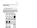
1
WARNING!
Improper operation of packaging machinery may result in damage to the
equipment or serious personal injury to the operator.
You must read and understand the contents ot this manual (especially the Safety
Precautions in Section 3) before you attempt to operate the machine.
OPERATOR MANUAL
Cont. Mo. Wrap-Around Case Packer
Machine No: M-2959
Built For: Nestle Nutritional Products Division
Manual Dated: 6/20/95
DOUGLAS MACHINE
3404 IOWA STREET. ALEXANDRIA, MINNESOTA 56308
TELEPHONE (612) 763-6587
FAX: (612) 763-5754
Copyright © 1995 Douglas Machine
General
INTRODUCTION
The Operator Manual has two purposes:
I) To explain what the DOUGLAS Wrap-Around Case Packer does.
2) To help \ou understand the safe operation of the machine.
WARNING!
Improper operation of packaging machinery may result in damage to the
equipment or serious personal injury to the operator.
You must read and understand the contents of this manual (especiaVy the Safety
Precautions in Section 3) before you attempt to operate the machine.
The manual has information about Wrap-Around Case Packers in general. Detailed instruc
tions for operating your custom-built Case Packer are included, as needed. Please pay careful
attention to the instructions. Theywill help you to operate the Case Packer efficiently and safe
lv.
IMPORTANT
Pay close attention to all DAtGER, WARNING, or CAUTION notices that are posted on
the machine or included in the manual. Before attempting to use this manual, he sure you are
familiar with the SAFETY PRECAUTIONS listed in Section 3. These PRECAUTR)NS are
repeated throughout the manual to alert operators and maintenance personnel to potentially
hazardous areas. DOUGLAS packaging equipment is designed br safe and convenient opera
tion. However, as with any piece of machinery. there is a potential for personal injury if safe
operating practices are not followed, or if safety features built into the equipment are
bypassed.
The hazard warnings that appear throughout this manual follow the suggested guidelines
for the industry:
DANGER! The hazard or unsafe practice will result in severe injury or death.
WARNING! The hazard or unsafe practice could result in severe injury or death.
CAUTION! The hazard or unsafe practice could result in minor injury or property damage.
1.2
General
TABLE OF CONTENTS
Section 1. GENERAL INFORMATION
1.2 Introduction
1.3 Table of Contents
1.4 Machine Description
Section 2. MACHINE OPERATION
2.1 Electrical Controls
2.2 Machine Loading
2.3 Wachine Operation
Section 3. SAFETY PRECAUTIONS
3.1 Safety Precautions
Section 4. TROUBLESHOOTING
4.1 TrouNeshooting
1.3
General
MACHINE DESCRIPTION
TIMING CHART & PLS SE’fliNGS
The function of the Continuous Motion Wrap-Around Case Packer is to remove one case
blank at a time from the power-fed magazine and set it up U-shaped in the flights, The end
flaps are. held out of the way by the flap guides, as the partially formed case is advanced for
product loading. Insertion of product is automatic. It may accumulate, separate, re-orient,
stack, or otherwise automatically arrange the product into the proper pack pattern prior to
loading. The filled ease is continually advanced for the minor flaps to he Lucked and held shut
by flap guides. The top panel is closed as the case advances through closing and sealing the
major flaps and the manufacturer’s flap with hot-melt glue. Compression is applied to allow
for setting of the adhesive. The finished cases arc discharged from the machine. Again,
depending on the design of the individual machine, the finished cases may he elevated, stack
ed, or otherwise rearranged as they are discharged from the case packer. Various sensing
devices are used to shut down the machine if an overload or any other malfunction occurs
during operation.
The above description applies to the operation of the Continuous Motion Wrap-Around
Case Packer in general. Machine N1-2959 is an automatic-loading machine. Product is received
on the inked conveyor, standing upright. auiomatically arranged in the proper load pattern
and loaded into ihe case. Afier loading, the case ill he conveyed through closing and sealing
the major flaps and fifth panel with hot melt glue. The completed case is then discharged from
the machine onto a separate take-away conveyor.
1A
01
•?..
-V
Cl
0.)
it
\
IV:
‘%%!
:
!
h
C.
(1(4
Cl
0
t,
t4
0
a
¶1
I
H
c%_
C
ci
—‘4
C
_c
d
((4
(:fl
L.4
y•
(114
IC)
((4
—(4
d
.1%
ci.
t
‘
.4.
;5
H
4
C
(.
Ci
—r.
;.
_*
H
a—
(.t
C)
(Its
;:
:
:
:
.
( :
4144
.C
&.}:
‘
cb
‘
:
i:
%C)
it)
1
1
I
K!
:(
0
t
J
(1(4
s_
$
‘.
.‘
‘L
H
r)
V
ç
C))
.s.
.
‘:
(:
w
‘13
:
—rOj
i__—1
c
c
..
.
d
0
(1-
U
1
.
(,9°_(4a
‘-‘I
•
:.
.
I.,
Operation
ELECTRICAL CONTROLS
This section of the manual will acquaint the operator with the basic layout of the electrical
control panels and the function of each of the controls.
NOTICE: All personnel must read and be familiar with the Safety Precautions (Page 3.1)
before attempting to operate this machine. Failure to observe these precautions may result
in damage to the machine or serious personal injury to the operator.
MAClW
JtXWRUW
YACWJM
fWF/ON
GLUE CONTROL
UFF/M
flRGFNCY STO’
000
**00
MAOHPE
START
CYCU
slur
tNFEED CONVEYOR
START
CLEANOUT MODE
QFFIQN
sior
BLANK SELECT
WAY/CASE
PRODUCT SELECT
6 P1(/12 PU
24 P(
Figure 2. 1 Operator’s Control Panel
The Operator’s Control Panel contains the foilo”ing controls and indicators:
2,1.1
Operation
MACHINE JOG RUN selector switch is used to determine the operating mode of the main
drive motor.
When the switch is in the JOG position. the motor will operate only while the MACHINE
START pushbutton is held activated. The motor will cease to operate when the pushbutton is
released.
When the switch is in the RUN position, the motor will run continuously after the
MACHINE START pushbutton is pressed.
MACHINE START and MACHINE) CYCI.E STOP pushbuttons control power to the
main drive motor.
MANUAL CYCLE pushbutton may he used to cycle the drive without product present.
VACUUM OFF/ON selector switch controls power to the vacuum system.
GLUE CONTROL OFF/ON selector switch controls power to the Glue Guns only. Glue
temperature controls and readouts are located on the Glue System Control Panel. For more
specific information, refer to the Glue System service manuals provided separately.
CLEANOUT MODE OFF/ON selector switch is used to cleanout the remaining product in
the machine.
INFEED CONVEYOR START and (INFEEI) CONVEYOR) STOP pushbuttons control
power to the infeed conveyor drive motors.
BLANK SELECF TRAY/CASE selector switch is used to electrically configure the machine
for the blank style to be run.
PRODUCT SELECT 6 P1(112 P1(124 PlC selector switch is used to electrically configure the
machine for the pack pattern to he run.
The MACHINE RESET pushbutton must he pressed to reset the machine br operation fol
lowing shutdown for an overload condition. Once a fault has been corrected, pressing RESET
will allow the machine to he restarted.
The EMERGENCY STOP pushbuttons are provided for the safety of personnel. The E
stop button is a puslrpull switch; once it is pressed in to stop. it must be pulled out to allow the
machine to run. The F-stop system will immediately stop the machine.
Note: Li-stops should be used only in an emergency!
The MACHINE OFFON locking selector switches are pronded for the safety of personnel.
Machine operation will be discontinued anytime the sw-itch is in the OFF position. The locking
mechanism on the machine lockout switch allows the operator to padlock the switch in the
OFF position while clearing Jams. The Machine ()ffion locking selector switch will he wired iii
series with the guard door interlocks and will control a machine safety- relay. This relay will he
hardwircd to stop alL motion except heat tunnel conveyors, fans, and infeed con\e\ors when
the Machine ()fltn locking selector switch is in the OFF position or one- of the truard doors is
open.
2.1.2
Operation
MACHINE LOADING
Load the MAGAZINE wIth blanks, making sure the machine adjustments arc correct for
the size case to he run. Be sure the blanks are properly positioned In the Magazine before
operatingthe machine. Refer to the sERVICE MANUAL if adiusinient is required.
Be sure that the product is in the proper position to enter the machine, as it arrives on the
INFEED CONVEYOR. Be sure the machine adjustments are correct for the product to he
run (Refer to the Service Manual for Adjustment and Changeover instructions).
Pour glue pellets into the GLUE SYSTEM RESERVOIR Turn the glue system ON from
the switch on the Glue System Panel. All glue system controls are located at the glue system
reservoir. Refer to the service manuals supplied by the hot melt system manufacturer for
recommended operating procedures and safety precautions.
WARNING!
Hot melt glue systems use glue at temperatures of about 350 degrees F. and
pressures in excess of 200 psi and any part of the glue system tank,
hoses, or guns can cause severe burns.
-
-
When filling glue tank, wear safety goggles, gloves, and other protective clothing
to prevent injury from splashed hot glue.
Refer to the service manuals provided l’v the glue system manufacturer for additional safety
precautions and specific operating instructions.
2,2
Operation
MACHINE OPERATION
This section of the manual is to acquaint the operator with the basic steps required to
operate the Continuous Motion Wrap-Around Case Packer.
NOTICE: All personnel must read and be familiar with the Safety Precautions (Page 3.1)
before attempting to operate this machine. Failure to observe these precautions may resuft
in damage to the machine or serious personal injury to the operator.
Start Up Procedure:
1) Connect the power source to the machine, if this has not already been
done, to begin heating the Glue System. The hot melt glue will require about
30-40 minutes to reach operating temperature.
2) Turn the GLUE CONTROL OFF/ON selector switch to “ON’.
3) Turn the PROOUCT SELECT 6 PK/12 PK/24 PK and BLANK STYLE
TRAY/CASE selector switches to the appropriate settings.
4) Turn the VACUUM OFF/ON selector switch to ON’.
5) Turn the MACHINE JOG/RUN selector switch to ‘RUN”,
6) Press the MACHINE START and INFEED CONVEYOR START
pushbuttons to begin automatic operation.
As long as product and blanks are available, the Case Packer will automatically set up and
load cases. Vhen beginning operation. cheek the fir st cases completed to be sure they are
properly squared and sealed. If any adjustments are required, shut down the machine and
make adjustments. Refrr to the SERVICE MANUAL if adjustment is needed,
WARNING!
Personnel entering the guard package, without first locking out the power,
risk accidental restart and potential serious personal injury or death.
Before you perform maintenance or make adjustments to DOUGLAS packaging
equipment. padlock the MACHINE OFFION locking selector switch in the “OFF
position before entering the machine.
Do not remove the padlock until all personnel are away from the machine and all
guard doors are closed.
Older machines not equipped with a locking selector switch must have the main
disconnect switch locked out. Those without a disconnect switch must be
unplugged from the power source. Secure the power cord so the machine cannot
be plugged in until all work is completed and all personnel are clear of the
machine.
2.3.1
Operation
Production Operation:
1) The Continuous Motion Wrap-Around Case Packer wAl set up and load
cases so long as there are blanks in the Magazine and product is available.
2) An overload of any overload clutch will shut down the machine. The
overload location is indicated by a message on the Alphanumeric Display.
CAUTION: To resume operation after a main drive overload, turn the manual
reset hub until the tripped overload clutch is re-engaged before attempting to
clear the jam
Turn the GLUE CONTROL OFF/ON selector switch to OFF to avoid accidental
injury from hot splashed glue
Lock out power and clear jam (or correct fault)
Restore power and press MACHINE RESET pushbutton
JOG machine to be sure no overload still exists
NOTE: Check position of machine before JOGGING and clear by hand any
case or product that obstructs a moving part be sure machine is at cycle stop
position before restart
-
Place in RUN mode, turn the GLUE CONTROL to ON, and resume automatic
operation
WARNING!
A tripped main drive overload clutch will allow machine parts to move when
a jam is cleared and can result in serious personal injury.
Reset the tripped overload clutch by turning the manual reset hub until the clutch
is engaged, then lock out the power before opening the guards to enter the
machine.
3) The machine will cease to operate if a Guard Door on the Case Packer is
opened. Close the door and press the MACHINE RESET pushbutton to
restart.
Shut Down Procedure:
1) Press the (MACHINE) CYCLE STOP and (INFEED CONVEYOR) STOP
pushbuttons.
2) Turn the VACUUM OFF/ON selector switch to OFF”.
3) Turn the GLUE CONTROL OFF/ON selector switch to OFF’.
4) Disconnect the power.
Cleanout Procedure:
1) Turn the VACUUM OFF/ON selector switch to ON.”
2) Turn the CLEANOUT MODE OFF/ON selector switch to ON”.
3) Once the machine cycle stops and ARRANGE INFEED PATTERN is
displayed, arrange the remaining product into balanced lanes to form one final
case (add or remove product as necessary).
4) Press the MACHINE RESET pushbutton to cycle the last case through the
machine.
5) Disconnect the power.
2.3.2
Safety
SAFETY PRECAUTIONS
WARNINGI
Contact with moving parts of packaging machinery is hazardous and may result in serious
personal injury or death.
DOUGLAS packaging machines must not be operated without all guards in place. Never operate
machine without all safety equipment in place.
NOTE: Some photographs were taken with guards removed, in order to show parts more clearly;
this in no way suggests that the machine be operated without all guards in place.
WARNING!
Personnel entering the guard package, without first locking out the power, risk accidental
restart and potential serious personal injury or death.
Before you perform maintenance or make adjustments to DOUGLAS packaging equipment,
padlock one of the MACHINE OFF/ON locking selector switches in the “OFF” position. Do not
remove the padlock until all personnel are away from the machine and all guard doors are closed.
Machines not equipped with locking selector switches must have the main disconnect switch
locked in the “OFF” position. Machines without a disconnect switch must be unplugged from the
power source. Secure the power cord so the machine cannot be plugged in until all work is
completed and all personnel are clear of the machine.
WARNING!
A tripped overload clutch will allow machine parts to move when a jam is cleared and can
result in serious personal injury.
Reset a tripped overload clutch by slowly turning the manual reset hub until the clutch is engaged.
then lock out the power before opening the guards to enter the machine.
WARNING!
Hazardous voltage in all parts of the electrical system can shock, burn, or cause death.
Before you enter any electrical enclosure or junction box, disconnect the machine from the
power source.
Ii your machine is equipped with a main disconnect switch, padlock the switch in the OFF
position. Machines that are not equipped with a disconnect switch must be unplugged from the
power source.
3.1.1
Safety
SAFETY PRECAUTIONS (CONTINUED)
WARNING!
Hot melt glue systems use glue at temperatures of about 350 degrees F. at pressures in
excess of 200 psi. Any part of the glue system tank, hoses, or guns can cause severe
burns.
-
-
WhÜe filling the glue tank, wear safety goggles, gloves, and other protective clothing to prevent
injury from splashed hot glue.
Refer to the service manuals provided by the glue system manufacturer for additional safety
precautions and specific operating instructions.
DANGER’
Contact with hot glue under pressure is hazardous and will cause severe burns.
Never perform maintenance on the glue system without first relieving the air pressure and glue
pressure.
WARNINGI
Attempting to remove hot melt glue from skin will peel the burned skin and cause additional
injury.
Do not attempt to remove hot melt glue that is stuck to the skin but cool the entire glue mass with
water and report to a physician immediately.
31.2
Troubleshooting
TROUBLESHOOTING
1. PROBLEM: Machine won’t operate in the JOG mode.
CAUSE/SOLUTION
a)
b)
c)
d)
e)
No power (electrical)
No air pressure
Guard door open
Emergency stop circuit is activated
Machine Off/On locking selector switch is in the “OFF position
2. PROBLEM: Machine won’t operate in RUN mode.
CAUSE/SOLUTION
a) No power (electrical)
b) Master Switch in the JOG position
c) Drive clutch is disengaged
d) Guard door open
e) Emergency stop circuit is activated
f) Machine Off/On locking selector switch is in the OFF” position
3. PROBLEM: Machine won’t pull blanks.
CAUSE/SOLUTION
a)
hi
c)
d)
Defective vacuum pump
Vacuum dump valve held open
Defective vacuum line
Vacuum cups not making proper contact with case
4. PROBLEM: Glue begins prematurely.
CAUSE/SOLUTION
a) Move glue enable sensing device downstream
b) Reset the glue system remote potentiometers
5. PROBLEM: Glue pattern can’t be adjusted.
CAUSE..SOLUTION
a) Detective potentiometer(s) (remote enclosure only)
b) Potentiometers in main electrical box should always read zero (0). Any other
setting invariably wUl cause a malfunction.
4.11
Troubleshooting
TROUBLESHOOTING (CONTINUED)
6. PROBLEM: No vacuum (Also see. Problem 3)
CAUSE/SOLUTION
a) Check hoses and fittings
b) Check vacuum pump filters
c) Check vacuum system controls
7. PROBLEM: Case blank set-up improper.
CAUSE/SOLUTION
a) Adjust blank holdback clips
b) Adjust bottom magazine bar to align case blank in magazine with set-up
vacuum cups
8. PROBLEM: No Glue.
CAUSE/SOLUTION
a) Glue reservoir not ON
b) Glue air pressure not ON
c) Glue not up to temperature
d) Clogged applicator nozzles--on machines provided with GLUE TEST
pushbuttons, test by placing a corrugated panel at the gun and using the
appropriate pushbutton to discharge glue onto the panel.
9. PROBLEM: Open case flap.
CAUSE/SOLUTION
a) Poor glue adhesion
b) Poor glue system functions
c) Insufficient compression--some machines require a bedplate adjustment to
cure this malfunction.
For more detailed explanation of machine adjustnienis and line-tuning, see the Sections on
Machine Set-up, Machine Adjustment. and Size Changeover.
For componenl parts maintenance, additional troubleshooting, and parts information. see
the separate O.E.M. Manual.
4 1 .2