1
MAXPRO-Net
Crosspoint Matrix Video Switching System
Hardware Installation Manual
HMXMU001018 – 10/06 - Rev. C
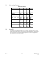
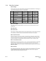
ISSUE
DATE
A
March 2005
Initial Release (PCN 1980)
B
March 2006
Revised Installation Instructions
C
October 2006
Rev. C
REVISIONS
Added detailed drawing for connecting to HVBMATPIT and
VideoBloX Chassis in Chapter 12. Revised the part numbers
for VideoBloX reference materials.
ii
HMXMU01018
10/06
FCC COMPLIANCE STATEMENT
INFORMATION TO THE USER: This equipment has been tested and found to comply
with the limits for a Class A digital device, pursuant to part 15 of the FCC rules. These
limits are designed to provide reasonable protection against harmful interference when
the equipment is operated in a commercial environment. This equipment generates,
uses, and can radiate radio frequency energy and, if not installed and used in
accordance with the instruction manual, may cause harmful interference to radio
communications. Operation of this equipment in a residential area is likely to cause
harmful interference in which case the users will be required to correct the interference at
their own expense.
CAUTION: Changes or modifications not expressly approved by the party responsible
for compliance could void the user’s authority to operate the equipment.
This Class A digital apparatus complies with Canadian ICES-003.
Cet appareil numérique de la Classe A est conforme à la norme NMB-003 du Canada.
USERS OF THE PRODUCT ARE RESPONSIBLE FOR CHECKING AND
COMPLYING WITH ALL FEDERAL, STATE, AND LOCAL LAWS AND
STATUTES CONCERNING THE MONITORING AND RECORDING OF
VIDEO AND AUDIO SIGNALS. HONEYWELL VIDEO SYSTEMS SHALL
NOT BE HELD RESPONSIBLE FOR THE USE OF THIS PRODUCT IN
VIOLATION OF CURRENT LAWS AND STATUTES.
Rev. C
iii
HMXMU01018
10/06
IMPORTANT SAFEGUARDS
1.
READ INSTRUCTIONS – All safety and operating instructions should be read before the unit is
operated.
2.
RETAIN INSTRUCTIONS – The safety and operating instructions should be retained for future
reference.
3.
HEED WARNINGS – All warnings on the unit and in the operating instructions should be adhered
to.
4.
FOLLOW INSTRUCTIONS – All operating and use instructions should be followed.
5.
CLEANING – Unplug the unit from the outlet before cleaning. Do not use liquid cleaners or
aerosol cleaners. Use a damp cloth for cleaning.
6.
ATTACHMENTS – Do not use attachments not recommended by the product manufacturer as
they may result in the risk of fire, electric shock, or injury to persons.
7.
WATER AND MOISTURE – Do not use this unit near water or in an unprotected outdoor
installation, or any area that is classified as a wet location.
8.
ACCESSORIES - Do not place this product on an unstable cart, stand, tripod,
bracket, or table. The product may fall, causing serious injury to a child or adult and
serious damage to the equipment. Use only with a cart, stand, tripod, bracket, or
table recommended by the manufacturer, or sold with the product. Any mounting of
the product should follow the manufacturer’s instructions and should use a mounting
accessory recommended by the manufacturer. Wall or shelf mounting should follow the
manufacturer’s instructions and should use a mounting kit approved by the manufacturer.
9.
A product and cart combination should be moved with care. Quick stops, excessive force, and
uneven surfaces may cause the product and cart combination to overturn.
10.
VENTILATION - Slots and openings in the cabinet and the back or bottom are provided for
ventilation and to ensure reliable operation of the equipment and to protect it from overheating.
These openings must not be blocked or covered. The openings should never be blocked by
placing the product on a bed, sofa, rug, or other similar surface. Equipment should never be
placed near or over a radiator or heat register. This product should not be placed in a built-in
installation, such as a bookcase or rack unless proper ventilation is provided or the manufacturer’s
instructions have been adhered to.
11.
POWER SOURCES – This product should be operated only from the type of power source
indicated on the marking label. If you are not sure of the type of power supplied to your home,
consult your product dealer or local power company. For products designed to operate from
battery power or other sources, refer to the operating instructions.
12.
GROUNDING OR POLARIZATION – The power supply supplied with this unit may be equipped
with a polarized alternating-current line plug (a plug having one blade wider than the other). This
plug will fit into the power outlet only one way. This is a safety feature. If you are unable to insert
the plug fully into the outlet, try reversing the plug. If the plug should still fail to fit, contact your
electrician to replace your obsolete outlet. Do not defeat the safety purpose of the polarized plug.
13.
OVERLOADING – Do not overload outlets and extension cords as this can result in a risk of fire or
electric shock.
Rev. C
iv
HMXMU01018
10/06
IMPORTANT SAFEGUARDS, CONTINUED
14.
POWER-CORD PROTECTION – Power supply cords should be routed so that they are not likely
to be walked on or pinched by items placed upon or against them, paying particular attention to
cords and plugs, convenience receptacles, and the point where they exit from the monitor.
15.
OBJECT AND LIQUID ENTRY – Never push objects of any kind into this unit through openings as
they may touch dangerous voltage points or short-out parts that could result in a fire or electric
shock. Never spill liquid of any kind on the unit.
16.
SERVICING – Do not attempt to service this unit yourself as opening or removing covers may
expose you to dangerous voltage or other hazards. Refer all servicing to qualified service
personnel.
17.
DAMAGE REQUIRING SERVICE – Unplug the unit from the outlet and refer servicing to qualified
service personnel under the following conditions:
a. When the power-supply cord or plug is damaged.
b. If liquids have been spilled, or objects have fallen into the unit.
c.
If the unit has been exposed to rain or water.
d. If the unit does not operate normally by following the operating instructions. Adjust only those
controls that are covered by the operating instructions as an improper adjustment of other
controls may result in damage and will often require extensive work by a qualified technician to
restore the unit to its normal operation.
e. If the unit has been dropped or the enclosure has been damaged.
f.
When the unit exhibits a distinct change in performance - this indicates a need for service.
18.
REPLACEMENT PARTS – When replacement parts are required, be sure the service technician
has used replacement parts specified by the manufacturer or have the same characteristics as the
original part. Unauthorized substitutions may result in fire, electric shock or other hazards.
19.
SAFETY CHECKS – Upon completion of any service or repairs to this unit, ask the service
technician to perform safety checks to determine that the unit is in proper operating condition.
20.
LIGHTNING AND POWER LINE SURGES – For added protection of this unit during a lightning
storm, or when it is left unattended and unused for long periods of time, unplug it from the wall
outlet and disconnect the cable system. This will prevent damage to the unit due to lightning and
power-line surges.
21.
HEAT – The product should be situated away from heat sources such as radiators, heat registers,
stoves, or other products (including amplifiers) that produce heat.
22.
INSTALLATION – Do not install the unit in an extremely hot or humid location, or in a place
subject to dust or mechanical vibration. The unit is not designed to be waterproof. Exposure to
rain or water may damage the unit.
23.
WALL OR CEILING MOUNTING – The product should be mounted to a wall or ceiling only as
recommended by the manufacturer
Rev. C
v
HMXMU01018
10/06
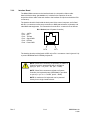
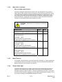
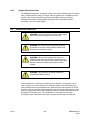
EXPLANATION OF GRAPHICAL SYMBOLS
The lightning flash with arrowhead symbol within an equilateral triangle is intended to
alert the user to the presence of uninsulated "dangerous voltage" within the product's
enclosure that may be of sufficient magnitude to constitute a risk of electric shock to
persons.
The exclamation point within an equilateral triangle is intended to alert the user to the
presence of important operating and maintenance (servicing) instruction in the literature
accompanying the product.
CAUTION
CAUTION
RISK OF ELECTRIC SHOCK
DO NOT OPEN
CAUTION: TO REDUCE THE RISK OF ELECTRIC SHOCK,
DO NOT REMOVE COVER (OR BACK).
NO USER-SERVICEABLE PARTS INSIDE.
REFER SERVICING TO QUALIFIED SERVICE PERSONNEL.
WARNINGS
WARNING: TO REDUCE THE RISK OF FIRE OR ELECTRIC SHOCK, DO
NOT EXPOSE THIS PRODUCT TO RAIN OR MOISTURE.
WARNING: DO NOT INSERT ANY METALLIC OBJECT THROUGH
VENTILATION GRILLS THIS PRODUCT TO RAIN OR MOISTURE.
WARNING: THIS UNIT MUST BE OPERATED WITH A PROPERLY
GROUNDED 3-PIN CONNECTION.
NON-OBSERVANCE OF THIS STANDARD PRACTICE MAY RESULT IN A
STATIC ELECTRICITY BUILD-UP THAT MAY RESULT IN AN ELECTRIC
SHOCK WHEN EXTERNAL CONNECTIONS ARE TOUCHED.
Rev. C
vi
HMXMU01018
10/06
WARNINGS, CONTINUED
WARNING: OBSERVE PRECAUTIONS FOR HANDLING
ELECTROSTATIC SENSITIVE DEVICES. Grounded wrist straps must
be worn and proper ESD safety precautions observed when handling
the electrostatic-sensitive printed circuit boards.
Rev. C
vii
HMXMU01018
10/06
SOFTWARE LICENSE AGREEMENT
Honeywell International Inc.
165 Eileen Way, Syosset, NY 11791.
You should carefully read the following terms and conditions. If you do not
consent to be bound by this License Agreement, you must promptly return
the unopened package to the person from whom you purchased it within
fifteen (15) days from date of purchase and your money will be refunded to
you by that person. If the person from whom you purchased this Software
fails to refund your money, contact HONEYWELL immediately at the
address shown above.
Important: This Software is security related. Access should be limited to
authorized individuals.
1. GRANT OF LICENSE. Subject to all terms and conditions hereof of Honeywell
International Inc. acting through its Security group ("HONEYWELL") does hereby
grant to the purchaser (the "Licensee") upon payment in full of the published
license fee, or other license fee agreed to in writing (the "License Fee") a
nontransferable, non exclusive license to use the enclosed software ("Licensed
Programs") provided herewith in Licensee's own business on a single computer
for a term commencing on the date of payment in full of the License Fee and
continuing in perpetuity unless terminated in accordance with the terms hereof.
2. PROPRIETARY RIGHTS. License hereby acknowledges that the Licensed
Programs including the algorithms contained therein are proprietary to
HONEYWELL. Licensee shall not sell, transfer, disclose, display or otherwise
make available any Licensed Programs or copies or portions thereof to any other
entity. Licensee agrees to secure and protect the Licensed Programs so as to
maintain the proprietary rights of HONEYWELL therein, including appropriate
instructions to and agreements with its employees.
3. DOCUMENTATION. The documentation supplied with the Licensed Programs
is the copyright property of HONEYWELL. Licensee shall not under any
circumstances divulge or permit to be divulged such documentation to any other
entity.
4. COPIES. Licensee shall not copy in whole or in part the Licensed Programs
or documentation provided however that Licensee shall be permitted to make one
(1) copy of the Licensed Programs solely for backup purposes provided that all
proprietary notices are reproduced thereon. Any such copy shall remain part of
the Licensed Programs and shall be subject to this agreement.
5. OBJECT CODE. Licensee understands and acknowledges that the Licensed
Programs consist of object code only and that HONEYWELL shall not supply
source code versions of the Licensed Programs. Licensee shall not create or
attempt to create by de-compilation or otherwise, the source code for the
Licensed Programs, or any part thereof.
6. SECURITY. Licensee acknowledges that the Licensed Programs are security
related and access to the Licensed Software should be limited to authorized
individuals. Licensee assumes full responsibility for use of the Licensed
Programs whether by authorized or unauthorized individuals. Licensee agrees
that the License Fee has been set in reliance upon the limitation on liability
contained herein and that such provisions are fair and not unconscionable.
HONEYWELL does not represent that the Licensed Programs may not be
compromised or circumvented, that the Licensed Programs will prevent any
personal injury or property loss by burglary, robbery, fire or otherwise, or that the
Licensed Programs will in all cases provide adequate warning or protection.
Licensee understands that a properly installed and maintained alarm may only
reduce the risk of burglary, robbery or fire without warning, but is not insurance or
a guarantee that such will not occur or that there will be no personal injury or
property loss as a result.
7.
DISCLAIMER OF WARRANTIES. HONEYWELL does not warrant that the
Licensed Programs will meet your requirements, that operation of the Licensed
Programs will be uninterrupted or error-free, or that all Licensed Programs’ errors
will be corrected. The entire risk as to the quality and performance of the
Licensed Programs is with you.
THE IMPLIED WARRANTIES OF
MERCHANTABILITY, FITNESS FOR A PARTICULAR PURPOSE AND
NONINFRINGEMENT ARE DISCLAIMED.
NO ORAL OR WRITTEN
INFORMATION OR ADVICE GIVEN BY HONEYWELL, ITS EMPLOYEES,
DISTRIBUTORS, DEALERS, OR AGENTS SHALL INCREASE THE SCOPE OF
THE ABOVE WARRANTIES OR CREATE ANY NEW WARRANTIES. SOME
JURISDICTIONS DO NOT ALLOW THE EXCLUSION OF IMPLIED
WARRANTIES, SO THE ABOVE EXCLUSION MAY NOT APPLY TO YOU. IN
THAT EVENT, ANY IMPLIED WARRANTIES ARE LIMITED IN DURATION TO
NINETY (90) DAYS FROM THE DATE OF DELIVERY OF THE LICENSED
PROGRAMS. This warranty gives you specific legal rights. You may have other
rights, which vary from state to state.
Rev. C
viii
8. LIMITATION OF REMEDIES. Licensee's exclusive remedy shall be either the
replacement of any diskette or other media not meeting the limited warranty set
forth above and which is returned to HONEYWELL with a copy of Licensee's paid
invoice or, if HONEYWELL is unable to deliver a replacement that is free of
defects, Licensee may terminate this Agreement by returning the Licensed
Programs and thereupon the License Fee shall be refunded. HONEYWELL shall
have no obligation under this Agreement if the Licensed Programs are altered or
improperly repaired or serviced by anyone other than HONEYWELL factory
service. For warranty service, return Licensed Programs transportation prepaid,
to HONEYWELL Factory Service, 165 Eileen Way, Syosset, New York 11791.
9. LIMITATION OF LIABILITY. REGARDLESS OF WHETHER ANY REMEDY
SET FORTH IN THIS AGREEMENT FAILS OF ITS ESSENTIAL PURPOSE, IN
NO EVENT WILL HONEYWELL OR ITS SUPPLIERS BE LIABLE TO YOU FOR
ANY SPECIAL, CONSEQUENTIAL, INDIRECT OR SIMILAR DAMAGES,
INCLUDING ANY LOST PROFITS OR LOST DATA ARISING OUT OF THE USE
OR INABILITY TO USE THE LICENSED PROGRAMS OR ANY DATA
SUPPLIED THEREWITH EVEN IF HONEYWELL OR ANYONE ELSE HAS
BEEN ADVISED OF THE POSSIBILITY OF SUCH DAMAGES, OR FOR ANY
CLAIM BY ANY OTHER PARTY. THIS PROVISION IS INCLUDED FOR THE
BENEFIT OF HONEYWELL AND ITS LOCAL REPRESENTATIVES, AND IS
ENFORCEABLE BY EACH OF THEM.
SOME JURISDICTIONS DO NOT ALLOW THE LIMITATION OR EXCLUSION
OF LIABILITY FOR INCIDENTAL OR CONSEQUENTIAL DAMAGES, SO THE
ABOVE LIMITATION OR EXCLUSION MAY NOT APPLY TO YOU.
IN NO CASE SHALL THE LIABILITY OF THE LICENSED PROGRAMS’
PROVIDERS OR OF HONEYWELL EXCEED THE PURCHASE PRICE PAID
FOR THE PRODUCT.
10. REGISTRATION. In order to qualify to receive notification of HONEYWELL
updates to the Licensed Programs, Licensee must complete and return a
Registration Form to HONEYWELL within twenty (20) days from date of
purchase. Notwithstanding, HONEYWELL is under no obligation to release
updates to the Licensed Programs.
11. TERMINATION. Upon the breach or non-compliance with any term or
provision of this agreement, HONEYWELL shall have the right to terminate the
license granted hereby by written notice to Licensee. Upon such termination
Licensee shall immediately turn over to HONEYWELL all copies of the Licensed
Programs and any documentation supplied in connection therewith. Such
remedy shall be in addition to and cumulative to any other remedies
HONEYWELL may have at law or in equity with respect to such breach or noncompliance.
12. GENERAL. This agreement is the complete and exclusive statement of the
understanding of the parties hereto with respect to the transaction contemplated
hereby and supersedes any and all prior proposals, understandings and
agreements. This Agreement may not be modified or altered except by a written
instrument signed by Licensee and an authorized representative of
HONEYWELL, its rights, duties or obligations under this Agreement to any person
or entity, in whole or in part. If any provision of this Agreement is invalid under
any applicable stature or rule of law it is to that shall be governed by the laws of
the State of New York and the sole venue for suit shall be in an appropriate state
or federal court located in the State and City of New York. The failure of
HONEYWELL to exercise in any respect any rights provided for herein shall not
be deemed a waiver of such right or any further Agreement may be brought more
than two (2) years after the date such cause of action shall have arisen.
HONEYWELL shall have the right to collect from Licensee any expensed incurred
including attorneys' fees in enforcing its right under this agreement.
HMXMU01018
10/06
PATENT AND TRADEMARK INFORMATION
One or more of the following patents or trademarks protects portions of MAX-1000, its software, and its
components.
Australian Patent
674652, 693914
US Patent
5923364, 5745166
British Patents
GB2305061 B, GB2323739 B, GB2323740 B, GB2323741 B
Singaporean Patent
9700491-5
Australian Trademarks 679926, 679927, 679928, 679929, 679930, 679931
US Trademark
Rev. C
75/142790
ix
HMXMC001018
10/06
MAXPRO-NET® TECHNICAL SUPPORT
REGISTRATION
License Key No.:
Site name: ..........................................................................................................................................................
Company:..........................................................................................................................................................
Contact person: ..................................................
Position/title:...................................................................
Mailing Address: ...............................................................................................................................................
.............................................................................................................................................................................
.............................................................................................................................................................................
Phone:...................................................................
Facsimile:........................................................................
Technical Support Information
Honeywell provides technical support by phone to the installers and users of our various products. We
are happy to assist with installation (wiring, connections and system planning), commissioning
(identifying cabling or interconnection problems, macro programming, reconfigurations) as well as
ongoing service, fault-finding and general maintenance advice.
Every licensed product receives technical support at no charge when the software has been licensed
through our technical support department. Call 972-620-6500 (1-800 796-2288 in North America) to
register your software via telephone or contact tech support at [email protected]
to register via email. The form can be mailed to Honeywell’s Technical Support Dept. located at 12880-A
Valley Branch Lane, Farmers Branch, TX 75234.
Other information
If you wish to minimize the requirement of technical support, Honeywell provides technical training
courses to allow our distributors and clients to further develop their own in depth knowledge and
understanding about our products.
Please contact our company for more information at
www.honeywellvideo.com.
I agree to abide by the terms and conditions as detailed in the software license agreement.
Please Sign/date and return to Honeywell Video Systems
_____________________________________
Signature
_______________________________
Date
Rev. C
x
HMXMU01018
10/06
MAXPRO-NET® TECHNICAL SUPPORT
"BEFORE YOU CONTACT TECHNICAL SUPPORT"
License Key No:
Before you call requesting technical support you should obtain the following information. This will save
you time and allow our support staff to attend to your difficulties promptly.
Have you registered the site?
As discussed on the registration form, you must have pre-registered your new MAXPRO-Net® software
licence PRIOR to requesting our technical support services. This should be done immediately to
activate you MAXPRO-Net® software.
What is the License key number?
You will need to know the licence number for the MAXPRO-Net® system you are ringing about. The
licence number is detailed at the top of this page as well as on the rear side of the SYSTEM floppy disk.
It can also be read from the title and registration page displayed within the system configuration editor
program, SETMAX.
You're now ready to contact technical support!
You are now ready to contact technical support. Telephone: 972-620-6500; Toll Free USA: 1-800-7962288. Email: [email protected]. Our staff may need to research your inquiry. This may
require time outside of the original phone call.
Rev. C
xi
HMXMU01018
10/06
Notes:
Rev. C
xii
HMXMU01018
10/06
TABLE OF CONTENTS
CHAPTER 1: GENERAL INFORMATION...............................................................................................1-1
1.1
INTRODUCTION ........................................................................................................................ 1-1
1.2
ACKNOWLEDGMENTS ............................................................................................................. 1-2
CHAPTER 2: ELECTROSTATIC DISCHARGE (ESD) ...........................................................................2-1
2.1
WARNINGS................................................................................................................................ 2-1
CHAPTER 3: WARRANTY AND MODULE REPLACEMENT.................................................................3-1
3.1
WARRANTY PROCEDURE ........................................................................................................ 3-1
3.2
LOAN PROCEDURE .................................................................................................................. 3-2
CHAPTER 4: TEST EQUIPMENT...........................................................................................................4-1
4.1
GENERAL REQUIREMENTS ..................................................................................................... 4-1
4.1.1 More Complex Faults.................................................................................................... 4-1
4.2
ON-SITE EQUIPMENT ............................................................................................................... 4-1
CHAPTER 5: DIAGNOSIS AND TROUBLESHOOTING ........................................................................5-1
5.1
GENERAL .................................................................................................................................. 5-1
5.2
EXAMPLE FAULT ANALYSIS..................................................................................................... 5-1
5.2.1 No Video from One Camera ......................................................................................... 5-1
5.2.2 No Video on One Monitor............................................................................................. 5-2
5.2.3 No Text on Monitor or Monitors.................................................................................... 5-2
5.2.4 No Operation from a Keyboard .................................................................................... 5-2
5.2.5 Total System Failure ..................................................................................................... 5-3
5.2.6 Problems with PTZ or Lens Operation ......................................................................... 5-3
5.3
MACRO ERRORS ...................................................................................................................... 5-4
5.3.1 ERRORLOG Report (in SetMax Configurator).............................................................. 5-6
5.4
DATA STREAM TESTING .......................................................................................................... 5-7
5.4.1 RS232 Breakout or Indicator Boxes ............................................................................. 5-7
5.4.2 PATCH232 Test Program ............................................................................................. 5-8
CHAPTER 6 : MODULE INFORMATION ...............................................................................................6-1
6.1
MODULES.................................................................................................................................. 6-1
CHAPTER 7: DATA SHEETS .................................................................................................................7-1
7.1
DATA SHEETS ........................................................................................................................... 7-1
7.2
MX04 & MX08 MULTI-PORT SERIAL CARDS......................................................................... 7.2-1
7.2.1 Switch Settings .......................................................................................................... 7.2-1
Rev. C
xiii
HMXMU01018
10/06
TABLE OF CONTENTS, CONTINUED
7.2.2
7.2.3
Jumper JP1................................................................................................................ 7.2-2
Interface Board .......................................................................................................... 7.2-3
7.3
MX18 SYSTEM CONTROLLER AUTO CHANGEOVER UNIT ................................................. 7.3-1
7.3.1 Integration of MX18 System Controller with MAXPRO-Net and VideoBloX Matrix
Chassis.......................................................................................................................... 7.3-5
7.4
RD85 VIDEO SELECTION MODULE ...................................................................................... 7.4-1
7.4.1 Operation ................................................................................................................... 7.4-1
7.4.2 Vertical Interval Switching.......................................................................................... 7.4-1
7.4.3 Clamp-To-Black Video Switching Transition ............................................................. 7.4-2
7.4.4 Used As A Black Source............................................................................................ 7.4-2
7.4.5 Used For Audio Switching ......................................................................................... 7.4-3
7.4.6 Diagnostic Video Connector...................................................................................... 7.4-3
7.4.7 Indicator ..................................................................................................................... 7.4-3
7.5
RD89 VIDEO FAIL/VIDEO ANALYSIS MODULE ..................................................................... 7.5-1
7.5.1 Operation ................................................................................................................... 7.5-1
7.5.2 Installation.................................................................................................................. 7.5-1
7.5.3 DIP Switch Definitions................................................................................................ 7.5-1
7.5.4 Video Analyzer Sensitivity Selection.......................................................................... 7.5-2
7.5.5 Indicators ................................................................................................................... 7.5-2
7.6
RD105/105B SUBRACK CONTROLLER MODULE................................................................. 7.6-1
7.7
RD200 TEXT INSERTION MODULE ....................................................................................... 7.7-1
7.8
MX205 TEXT INSERTION MODULE ....................................................................................... 7.8-1
7.9
RD315 PTZ SITE COMMUNICATIONS MODULE................................................................... 7.9-1
7.9.1 PTZ Site Wiring .......................................................................................................... 7.9-2
7.9.2 DIP Switch Setting ..................................................................................................... 7.9-2
7.9.3 Setting Audio Communication Link Points................................................................ 7.9-3
7.9.4 Direct RS-232 Control Or Data Testing ..................................................................... 7.9-4
7.9.5 LED Indicators ........................................................................................................... 7.9-4
7.9.6 Subrack Slot D25 Connector Pin Allocations ............................................................ 7.9-5
7.10
RD316 MODULE - RS-422/485 PTZ SITE TRANSMITTER MODULE ................................... 7.10-1
7.10.1 General .................................................................................................................... 7.10-1
7.10.2 Installation................................................................................................................ 7.10-1
7.10.3 Indicators ................................................................................................................. 7.10-2
7.10.4 DIP Switches............................................................................................................ 7.10-2
7.10.5 Diamond Electronics - FastScan/SmartScan .......................................................... 7.10-3
7.10.6 PELCO - Intercept/Legacy – AD Format.................................................................. 7.10-5
7.10.7 PELCO - Intercept/Legacy – Pelco 9750 Format..................................................... 7.10-5
7.10.8 PELCO – Coaxitron Interface Format ...................................................................... 7.10-6
7.10.9 Maxpro – RS-485 – Non Polling............................................................................... 7.10-6
7.10.10 Maxpro – RS-485 – Polling ...................................................................................... 7.10-6
7.10.11 Vicon Standard ........................................................................................................ 7.10-6
Rev. C
xiv
HMXMU01018
10/06
TABLE OF CONTENTS, CONTINUED
7.10.12
7.10.13
7.10.14
7.10.15
7.10.16
7.10.17
7.10.18
7.10.19
7.10.20
7.10.21
7.10.22
7.10.23
7.10.24
7.10.25
7.10.26
7.10.27
7.10.28
7.10.29
7.10.30
7.10.31
Vicon Extended........................................................................................................ 7.10-7
Panasonic - WV-CS600/WV-RM70, WV-CS600A/WV-RM70, and WV-CSR600 ...... 7.10-7
Panasonic - WV-CS850 Series ................................................................................ 7.10-8
American Dynamics................................................................................................. 7.10-9
Philips/Burle............................................................................................................. 7.10-9
Star/Chugai/Sanyo SMD12P, SMD20P, VCC9200P.............................................. 7.10-10
Mark Mercer........................................................................................................... 7.10-10
Videv ...................................................................................................................... 7.10-10
VCL ........................................................................................................................ 7.10-10
SpeedDome........................................................................................................... 7.10-11
Kalatel .................................................................................................................... 7.10-11
Baxall ..................................................................................................................... 7.10-11
Bocom ................................................................................................................... 7.10-12
Ultrak KX Series Multiplexors................................................................................. 7.10-12
Ranger FLIR ........................................................................................................... 7.10-14
Elbex ...................................................................................................................... 7.10-14
Tracam................................................................................................................... 7.10-15
JVC ........................................................................................................................ 7.10-15
VST – RS-485 – Unidirectional............................................................................... 7.10-15
VST – RS-485 – Bidirectional ................................................................................. 7.10-16
7.11
RD378E PTZ SITE RECEIVER .............................................................................................. 7.11-1
7.11.1 Features ................................................................................................................... 7.11-1
7.11.2 Power Supply........................................................................................................... 7.11-2
7.11.3 Communications...................................................................................................... 7.11-2
7.11.4 Motor Drive .............................................................................................................. 7.11-5
7.11.5 Motor Time Out........................................................................................................ 7.11-8
7.11.6 Tamper Alarm Input ................................................................................................. 7.11-8
7.11.7 Installation Notes .................................................................................................... 7.11-8
7.11.8 Suitable cable sizing for PTZ heads when connecting to Site Receivers ............... 7.11-8
7.11.9 RD378 PRIVACY ZONES ......................................................................................... 7.11-9
7.11.10 IO-378 Optional I/O Expansion Board ........................................................................... 12
7.11.11 RL-378 Optional I/O Expansion Board with 240V Relays.............................................. 14
7.11.12 E.M.C Compliance - Installation Requirements..................................................... 7.11-16
7.12
RD379 PTZ SITE RECEIVER................................................................................................. 7.12-1
7.12.1 Features ................................................................................................................... 7.12-1
7.12.2 Power Supply........................................................................................................... 7.12-2
7.12.3 Communications...................................................................................................... 7.12-2
7.12.4 Motor Drive .............................................................................................................. 7.12-5
7.12.5 Motor Time Out........................................................................................................ 7.12-7
7.12.6 Tamper Alarm Input ................................................................................................. 7.12-7
7.12.7 Installation Notes ..................................................................................................... 7.12-8
7.12.8 Suitable cable sizing for PTZ heads when connecting to Site Receivers ............... 7.12-8
Rev. C
xv
HMXMU01018
10/06
TABLE OF CONTENTS, CONTINUED
7.12.9 IO-378 Optional I/O Expansion Board ..................................................................... 7.12-9
7.12.10 RL-378 Optional I/O Expansion Board with 240V Relays...................................... 7.12-10
7.12.11 E.M.C Compliance - Installation Requirements..................................................... 7.12-12
7.13
RD400 ALARM INPUT MODULE........................................................................................... 7.13-1
7.13.1 Contact Closure or End-Of-Line Modes .................................................................. 7.13-1
7.13.2 Sensing.................................................................................................................... 7.13-1
7.13.3 Wiring Connections ................................................................................................. 7.13-2
7.13.4 DIP Switch Settings ................................................................................................. 7.13-2
7.14
HMX440 RELAY OUTPUT MODULE..................................................................................... 7.14-1
7.14.1 Wiring Connections ................................................................................................. 7.14-2
7.14.2 Function Cross Reference Table For Direct Control ............................................... 7.14-2
7.15
RD490 UNIVERSAL PERIPHERAL INTERFACE ................................................................... 7.15-1
7.15.1 General .................................................................................................................... 7.15-1
7.15.2 Operation ................................................................................................................. 7.15-1
7.15.3 Connector Details .................................................................................................... 7.15-2
7.15.4 Infra-red LED wiring ................................................................................................. 7.15-3
7.15.5 Installation Aid – L12................................................................................................ 7.15-3
7.15.6 DIP Switch Settings ................................................................................................. 7.15-3
7.15.7 Alarm Sense Setup (SW1 4-way DIP switch) .......................................................... 7.15-5
7.15.8 Error Display ............................................................................................................ 7.15-7
7.15.9 Description of Control Functions............................................................................. 7.15-8
7.15.10 I.R. Learn Mode ...................................................................................................... 7.15-9
7.15.11 Workshop Test Mode ............................................................................................ 7.15-10
7.16
RD494 RESISTIVE LADDER PERIPHERAL UNIVERSAL INTERFACE MODULE ................. 7.16-1
7.16.1 General .................................................................................................................... 7.16-1
7.16.2 Operation ................................................................................................................. 7.16-1
7.16.3 Connector Details .................................................................................................... 7.16-3
7.16.4 Description of Control Functions............................................................................. 7.16-6
7.16.5 Workshop Test Mode .............................................................................................. 7.16-8
7.17
HEGS5300 KEYBOARD........................................................................................................ 7.17-1
7.17.1 Setup Mode ............................................................................................................. 7.17-1
7.17.2 3-Dimensional Joystick............................................................................................ 7.17-2
7.17.3 Wiring Connections ................................................................................................. 7.17-2
7.17.4 Keycode Table......................................................................................................... 7.17-3
7.17.5 Cable Lengths.......................................................................................................... 7.17-4
7.17.6 E.M.C. Compliance - Installation Requirements...................................................... 7.17-7
7.17.7 Special Notes - Previous Versions of RD-530 ......................................................... 7.17-8
7.17.8 DIP Switch Settings ................................................................................................. 7.17-8
7.18
HMXPS9 SYSTEM POWER SUPPLY.................................................................................... 7.18-1
7.18.1 Output Protection For HMXPS9............................................................................... 7.18-1
7.18.2 Interconnecting HMXPS9 to Canon Style Sockets.................................................. 7.18-1
Rev. C
xvi
HMXMU01018
10/06
TABLE OF CONTENTS, CONTINUED
7.19
RD9021 I/O INTERFACE MODULE....................................................................................... 7.19-1
7.19.1 General .................................................................................................................... 7.19-1
7.19.2 Installation................................................................................................................ 7.19-1
7.20
HMX1676 TEXT INSERTION SUBRACK WITH VCR CONTROL SUBRACK......................... 7.20-1
7.20.1 General .................................................................................................................... 7.20-1
7.20.2 Video Slots............................................................................................................... 7.20-1
7.20.3 I/O Slots ................................................................................................................... 7.20-1
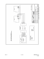
CHAPTER 8: DIAGRAMS.......................................................................................................................8-1
8.1
INTRODUCTION ........................................................................................................................ 8-1
8.2
SUBRACK CONNECTIONS ....................................................................................................... 8-1
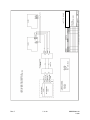
8.4
PT321 CONNECTIONS.............................................................................................................. 8-4
8.5
PT323 CONNECTIONS.............................................................................................................. 8-6
8.6
PT324 CONNECTIONS.............................................................................................................. 8-7
8.7
PT325 CONNECTIONS.............................................................................................................. 8-8
8.8
PT327 CONNECTIONS.............................................................................................................. 8-9
8.9
RD390 LENS CONTROL EMULATOR CONNECTIONS .......................................................... 8-10
8.10
I/O MODULE D25 CONNECTIONS ......................................................................................... 8-11
CHAPTER 9 : SPECIALIST DOCUMENTATION ...................................................................................9-1
9.1
MAXPRO-NET UPGRADE INSTALLATION (FROM MAX-1000)................................................ 9-1
9.1.1 Directions...................................................................................................................... 9-1
9.2
RS-232 BASICS ......................................................................................................................... 9-2
9.3
VCR CONNECTIONS USING THE RD9022............................................................................... 9-3
9.3.1 Cable Manufacture ....................................................................................................... 9-3
9.4
SINGLE SYSTEM JUNCTIONS (SPLIT MATRICES).................................................................. 9-3
9.5
RECOMMENDED SIGNAL CABLES.......................................................................................... 9-5
9.5.1 Video cable ................................................................................................................... 9-5
9.5.2 Audio (telemetry) cable ................................................................................................ 9-6
9.5.3 RS-232 and RS-422/485 cable ..................................................................................... 9-7
9.5.4 Keyboard Extension Cable ........................................................................................... 9-8
9.6
POWER DISTRIBUTION ............................................................................................................ 9-8
9.6.1 Mains Power Distribution............................................................................................ 9-10
9.7
SUBRACK IDENTIFICATION ................................................................................................... 9-11
9.8
SUBRACK CURRENT CONSUMPTION................................................................................... 9-12
9.9
MODULE CURRENT CONSUMPTION .................................................................................... 9-14
CHAPTER 10 : SYSTEM CONFIGURATION .......................................................................................10-1
10.1 THE SETMAX CONFIGURATOR FOR MAXPRO-NET.................................................................. 10-1
Rev. C
xvii
HMXMU01018
10/06
TABLE OF CONTENTS, CONTINUED
CHAPTER 11: HD-SERIES QUICK-START GUIDE.............................................................................11-1
11.1
GENERAL ................................................................................................................................ 11-1
11.2
UNPACKING ............................................................................................................................ 11-1
11.3
CONNECTIONS....................................................................................................................... 11-1
11.4
STARTUP ................................................................................................................................. 11-2
11.5
BASE CONFIGURATION ......................................................................................................... 11-2
11.6
CUSTOMIZING YOUR CONFIGURATION ............................................................................... 11-3
11.6.1 Enabling Video Fail/Level Detection........................................................................... 11-3
11.6.2 Pan/Tilt Control ........................................................................................................... 11-3
11.7
CONTROL CARD DIP SWITCH SETTINGS ............................................................................. 11-4
11.8
SUBRACK ADDRESSING ........................................................................................................ 11-7
11.9
SUBRACK BAUD RATE ........................................................................................................... 11-7
11.10
SUBRACK DATA PORTS ......................................................................................................... 11-7
11.11
ALARM DETECTION MODE .................................................................................................... 11-7
11.12
HD-SERIES SUBRACKS AS COMBINERS.............................................................................. 11-8
11.13
INSTALLATION TIP .................................................................................................................. 11-8
11.14
TECHNICAL NOTES ................................................................................................................ 11-9
11.14.1 Hardware Mapping ..................................................................................................... 11-9
11.14.2 Vertical Interval Switching......................................................................................... 11-10
11.14.3 Black Pause Switching ............................................................................................. 11-10
11.14.4 PAL/NTSC Determination ......................................................................................... 11-10
11.14.5 Cascading Multiple HMX32128 Subracks ................................................................ 11-11
11.15
HMX4248 I/O MODULE FOR HMX32128 .............................................................................. 11-12
11.15.1 General ................................................................................................................... 11-12
11.15.2 Installation................................................................................................................. 11-12
11.15.3 Contact Closure, or End-Of-Line Modes .................................................................. 11-12
11.15.4 Specifications (MX-4248).......................................................................................... 11-12
11.16
USING THE DIAMOND DOME CAMERA SET-UP MENU ..................................................... 11-13
11.16.1 Equipment Configuration.......................................................................................... 11-13
11.16.2 Operation .................................................................................................................. 11-14
11.17
HMX128 MODULES WITH 3 DIP SWITCHES (OLDER VERSIONS) ..................................... 11-15
11.18 MX826 VIDEO DISTRIBUTION MODULE ................................................................................. 11-16
11.18.1 General ..................................................................................................................... 11-16
11.18.2 Operation .................................................................................................................. 11-16
11.18.3 Installation................................................................................................................. 11-17
Rev. C
xviii
HMXMU01018
10/06
TABLE OF CONTENTS, CONTINUED
11.19
HMX832 AND HMX832L VIDEO INPUT AND SWITCHING MODULES................................. 11-18
11.19.1 General ..................................................................................................................... 11-18
11.19.2 HMX832 Connectors ................................................................................................ 11-18
11.19.3 HMX832L Connectors............................................................................................... 11-18
11.19.4 Operation .................................................................................................................. 11-18
11.19.5 Installation Accessories ............................................................................................ 11-19
CHAPTER 12: VIDEOBLOX INTEGRATION WITH MAXPRO-NET .....................................................12-1
12.1
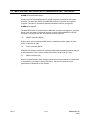
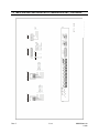
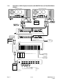
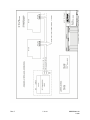
CONNECTION DIAGRAMS...................................................................................................... 12-1
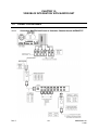
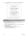
12.1.1 Connecting MAXPRO-Net Server to Videoblox Chassis through HVBMATPIT.......... 12-1
12.1.2 Connecting MAXPRO-Net Server to Videoblox Chassis through VB Converter ........ 12-2
12.1.3 Connecting MAXPRO-Net Server to Videoblox Chassis through RS422 PCI Card ... 12-3
12.2
REFERENCES ......................................................................................................................... 12-3
Rev. C
xix
HMXMU01018
10/06
Notes:
Rev. C
xx
HMXMU01018
10/06
CHAPTER 1:
GENERAL INFORMATION
1.1
INTRODUCTION
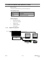
MAXPRO-Net combines custom designed software with a high performing Windows
2003 Server resulting in Honeywell's Turn Key Centralized Management Console Server
designed for system configuration, system management and system monitoring of
Honeywell’s crosspoint matrix video switchers. The modular hardware architecture and
flexible configuration software design simplifies troubleshooting for customers or
Honeywell Field Service Engineers. The equipment utilizes replaceable modules fitted
with LED indicators to assist with fault diagnosis.
Before attempting fault finding on any system some knowledge of the basic operation is
required. This is most easily obtained by reference to the system block diagram. The
system access codes are required for some of the more sophisticated diagnostic
facilities provided within the MAXPRO-Net crosspoint matrix video switch.
This is followed by a simple logical one step at a time identification of actions and
operation. By analyzing the LED indications and swapping suspect modules within the
subrack it is possible to locate faults remotely with a Technician in front of the rack and
an Engineer on the telephone.
For all of the following information it is assumed that service is being carried out on a
previously operating system, that is, one that has been commissioned correctly and has
become faulty after some time of normal operation.
Fault finding techniques differ slightly during commissioning and are usually more
complex and difficult to isolate as they often occur in conjunction with other faults
masking the symptoms and responses to changes made.
Incorrect programming can falsely present itself as faulty equipment. Some of the
module exchange techniques may be of assistance in verifying incorrect programming.
However, this manual does not attempt to cover any aspects of macro programming.
This manual is intended for service of the MAXPRO-Net only and does not attempt to
solve problems with cameras, monitors or video link equipment. General purpose
service manuals and aids can be ordered from your system agent.
Rev. C
1-1
HMXMU01018
10/06
1.2
ACKNOWLEDGMENTS
WINDOWS®
Registered trademark of the Microsoft Corporation
SMARTEXT™ Trademark of Honeywell, Inc.
FLASHBACK™ Trademark of Honeywell, Inc.
MAXPRO™ and MAXPRO SYSTEMS LOGO are Registered Trademarks of Honeywell,
Inc.
Rev. C
1-2
HMXMU01018
10/06
CHAPTER 2:
ELECTROSTATIC DISCHARGE (ESD)
2.1
WARNINGS
All circuitry in this system contains a considerable number of MOS and other static
sensitive components. Static damage may or may not cause instant failure of a circuit
and therefore, could go undetected. This damage can cause reduced life span or early
system failure.
(a) If possible, switch off the RD-PS6/9 supplying the subrack under service when
changing modules. Module exchange can be done while the system is powered,
however, special care should be taken to ensure that modules are plugged in and
out squarely and do not touch other adjacent modules.
(b) Always discharge static from yourself by touching a conductive part of the main
equipment cabinet before handling any circuit module.
(c) All precautions should be taken not to handle electronic connection edges of circuit
boards. This is to minimize the chance of static damage and to avoid deposit of
acids from the skin on critical surfaces.
(d) Do not poke your finger at components or touch IC pins. These are all good ways of
causing static damage. Components are also physically delicate.
(e) All circuit modules equipped with memory components are to be protected from
sunlight and strong UV-light.
(f) If static potential is high from carpet floor coverings, chairs, or other furnishings,
additional grounding should be used by way of a wrist strap for the person handling
the installation of cards.
(g) Circuit modules with backup batteries can be easily damaged, as some parts of the
circuit are still live even when un-plugged. The backup battery itself can cause
damage if conductive objects make contact with the circuit board.
(h) To protect against physical damage leave individual circuit boards in their boxes and
in their anti-static bags until they are required.
Rev. C
2-1
HMXMU01018
10/06
2.1 WARNINGS, CONTINUED
(i) When plugging leads into the back of a sub-rack or computer, always make
personal contact with the chassis of the sub-rack or computer before mating the
connectors. This will, at least, equalize static levels between the lead and the
computer.
WARNING: These procedures apply equally to both
working and faulty circuit modules. Careless handling,
storage and transporting will cause secondary or future
faults.
Rev. C
2-2
HMXMU01018
10/06
CHAPTER 3:
WARRANTY AND MODULE REPLACEMENT
3.1
WARRANTY PROCEDURE
Modules are exchangeable items, and will be replaced at no charge during the warranty
period, provided the damage is a normal electronic component failure. Outside the
warranty period, or if a module has been damaged by misuse, modules will be repaired
in our workshops for a flat rate service charge.
The replacement module warranty continues until the original warranty period expires.
Out of warranty repairs or exchanges are warranted only for faulty workmanship.
Warranty dispatched modules will be invoiced at list price. Upon return of the faulty
module, the invoice will be canceled or reduced to the exchange module value.
After determining that a unit is faulty and still within the warranty period, please use the
following procedure. Failure to do so may delay the process of repairing / replacing and
returning the unit.
Contact Honeywell or your System Supplier to obtain a Return Authorization Number
(RAN). This enables us to track your unit through our system.
Pack the units appropriately, in the original packing if possible. Honeywell will charge for
repairs to equipment where damage has been caused by poor packing or transport.
Mark the Return Authorization Number (RAN) clearly on the outside of the box before
shipping as well as in the accompanying documentation.
If the unit being returned is for repair from outside of Australia, the paperwork should
clearly mention the following: the original purchase order number, Return Authorization
Number (RAN) and, that the units are to be repaired. Serial numbers are often helpful.
Freight for all repairs is borne by the customer at all times. Please state your preferred
carrier, account numbers and any other details required for returning your units after
repair.
Repairs are normally completed quickly. If you wish to enquire about the status of a
repair please have your Return Authorization Number (RAN) reference ready.
Following this procedure will greatly assist Honeywell in turning around your unit quickly
and minimize the cost and interruption to your customers.
Rev. C
3-1
HMXMU01018
10/06
3.2
LOAN PROCEDURE
When requesting loan equipment, please use the following procedure. Failure to do so
may delay the process of receiving goods, or affect further loan requests.
Contact Honeywell to obtain a Return Authority Number (RAN). This enables us to track
your loan equipment through our system.
Fax an official company purchase order to Honeywell for the full value of the goods
required for loan purposes. Ensure the Return Authority Number (RAN) is clearly stated
on the purchase order to avoid delays. Discounts DO NOT apply to loan equipment.
Freight for all loan equipment from and to Honeywell is borne by the customer at all
times. Please state your preferred carrier, account numbers and any other details
required on the purchase order.
Loan equipment is provided for fourteen days only. Any extension to this time must be
approved by Honeywell. Failure to return equipment within fourteen days can affect
future loan services and/or credit facilities.
All loan equipment (if not covered by warranty conditions) is subject to a standard 20%
re-stocking fee. All loan equipment must be re-packed in the original packing and must
not have any damage. Honeywell will charge for repairs to equipment where damage
has been caused by poor packing or transport.
Mark the Return Authority Number (RAN) clearly on the outside of the box before
shipping as well as in the accompanying documentation. Do NOT write directly on the
carton. If the RA number cannot be identified, the product will be returned immediately at
your expense.
Following this procedure will greatly assist Honeywell in providing this service.
Rev. C
3-2
HMXMU01018
10/06
CHAPTER 4:
TEST EQUIPMENT
4.1
4.1.1
GENERAL REQUIREMENTS
•
BNC patch cables and joiners
•
Test monitor (preferably portable)
•
Test video cord 3 pin IDC to BNC
•
Digital multimeter
•
75 ohm termination
•
BNC T adapter
•
RS-232 indicator modules and Patch Cords
More Complex Faults
•
20 MHz Oscilloscope
•
Video generator
•
Test program PATCH232.EXE (Supplied on the MAXTOOLS disk)
•
Null modem cables and adapters
•
4.2
IBM compatible computer with at least two serial ports (Preferably a portable
unit)
ON-SITE EQUIPMENT
In most installations some form of communication is required from the camera to the
control room monitors. VHF or UHF hand held radios best suit this requirement. Mobile
telephones sometimes have application in this area. Adjustments such as focus, iris and
camera position can usually be set in this manner. Back focus can also be done "in situ"
although better results are usually obtained by doing this under controlled conditions in
the workshop.
Rev. C
4-1
HMXMU01018
10/06
Notes:
Rev. C
4-2
HMXMU01018
10/06
CHAPTER 5:
DIAGNOSIS AND TROUBLESHOOTING
5.1
GENERAL
All VIDEO TYPE modules have an auxiliary 75 ohm output connection point available on
the front edge of the module. This provides for simple connection of test equipment
when system commissioning or servicing is required. This test video output connector is
a 3 pin, 0.1" spaced, male IDC type, where the center pin is the active video output and
the other two pins are grounded.
This test video output on the modules gives the technician, total front panel access to all
video output channels in a switching system, without the need to remove or patch
connections on the rear of the video switching subrack equipment.
5.2
EXAMPLE FAULT ANALYSIS
As every system is different, only general techniques for fault location can be provided.
Fault location can be performed by using the procedures and applying them to the
actual block schematic for your specific system.
It is essential that the service engineer has a good operational knowledge of the specific
system in question. Remember that with the macros, the system features can be wide
and varied. First study the block schematic to understand the video paths, the modules
of concern, and their slot locations. A few hours spent on this at this point could save
many hours of frustration.
Remember that each video module has a monitor point on the front of it for easy access
of the test monitor. Every module has at least one LED indicator to show data flow to the
module and bi-directional modules have LEDs for data flow in both directions and CPU
fail indicators. LEDs show all normal operation actions and all abnormal operations
either by not flashing or flashing at the wrong time.
Do not forget to look at the error log file first. It is very useful for intermittent fault locating
as it may have logged the fault and the slot location in many cases.
5.2.1
No Video from One Camera
If a specific camera cannot be viewed on any monitor that had the correct source group
access, then check with a test monitor that video is present at the input to the sub-rack.
If so, move the camera cable to another (spare) input which will have to be programmed
for the required camera number PTZ details, etc. If it then works, then the input VDA
fitted to the back of the sub-rack is most likely faulty.
Rev. C
5-1
HMXMU01018
10/06
5.2.2
No Video on One Monitor
Assuming that the monitor operation has been checked by applying a direct signal, the
fault could be in a number of modules. For a small system only one RD-85 and one RD200 are in the video circuit for the monitor channel. It is critical that the block diagram is
used to locate the signal path and modules related to the faulty channel.
The first step would be to make a normal keyboard selection for this monitor. While
doing this, watch the LED indicators on the modules and check that a yellow LED
flashes on the subrack RD-105, RD-85 and the RD-200. If they do, then it is reasonable
to assume that the communication to these modules is operating.
There are now two ways to determine the faulty module. The first is to swap one at a
time with modules from an operating channel. The second is to monitor the video test
output on the front of each module with the test monitor.
If the data indicator LEDs do not flash on one of the modules, then it would be worth
swapping this with another channel to verify its operation. Press the Reset button on the
upper front edge of the sub-rack controller (RD105) and allow a few seconds for the
system to warm boot before continuing with the tests.
5.2.3
No Text on Monitor or Monitors
Very similar to test as for the above. Make a normal action and check that the data LEDs
flash. If text is lost on one monitor, only then swap the module with another and reset. If
there is no text, or no text update on any monitor and all the RD-200 modules are in one
subrack, then check that the data LED is flashing on the RD-105 module when
selections are made from a keyboard logged to the faulty monitor. If not, then there may
be a communication problem with the control computer or the subrack RD-105 module.
Use an RS-232 tester or PATCH232 to check data flow.
5.2.4
No Operation from a Keyboard
The symptoms of this fault can occur because a keyboard is logged off. Check this first.
Check that the cable from the keyboard has not been damaged by stretching or
excessive flexing and that the keyboard has power. If the cable and connections seem
okay, then insert an RS-232 tester and check that the LEDs flash when a keyboard
action is made. If the LEDs do flash, then it may be necessary to swap with another
keyboard to check the input port to the computer (do not forget to set the correct
keyboard ID code). Alternatively, use PATCH232 to verify that the data from the
keyboard is of good quality. Always check the transmission speed for keyboards
especially if it is transferred across a link such as microwave or fiber optic. Use of in-built
test modes as detailed on page (5.8) may be helpful.
Rev. C
5-2
HMXMU01018
10/06
5.2.5
Total System Failure
If there are pictures but they cannot be changed, then note the text inserters. Write
down any special messages that may be displayed.
The system will try and place system error messages on the text inserters if the system
control computer is in difficulty. The first fix would be to try a RESET on the system RDAT100 control computer. This may solve the problem. Wait a few moments for the
system to re-boot. If there is no action, then connect the test monitor to the menu video
output on the back of the control computer.
Re-set the system again. Check the progress of the boot on the test monitor. It may be
that a very strong main's power corruption spike has caused change in the CMOS setup
RAM. This will be evident in the progress of the boot. If the computer is operating
correctly but the rest of the system is blank then check the power supply LED indicators.
Ensure that the LEDs are on for all outputs. If none are on, then the RD-PS6/9 may have
a blown mains fuse. Circuit diagrams are given for the power supplies, as a power
supply failure could cause significant down-time of the system. On site repair may be
carried out if required.
The power supplies are well protected with fuses so it is very unlikely that components in
a power supply will go faulty.
5.2.6
Problems with PTZ or Lens Operation
From operations on the keyboard, it can be determined if a problem is partial at a site or
a complete site fail. A loss of communications at a site will cause the system alarm to
activate for a PTZ fail.
In some instances a loss of video from the site may occur simultaneously. This
combined fault would almost certainly indicate a loss of power at the site.
On opening the site, the receiver LED indicators show the status of all fuses. If a site is
having problems with part of a control function, it is most likely that the problem is in the
external hardware of the PTZ or lens.
Most PTZ site faults occur because of poor installation and the subsequent mechanical
damage to the wiring from movement.
The error log file would also have logged any fail or restore action on the PTZ site
receiver, even if it is only because of a temporary loss of power.
However, if a PTZ site has genuinely failed then the LEDs tell the story. First is the
communications LED flashing off and on. If not, then a check of the cabling to the site
may be required.
If the power supply boards have blown fuses and the change of a fuse does not fix the
problem and the fuse blows again, a replacement of the control board may be required.
PTZ sites on poles are often susceptible to lightning strike. If this happens, then the site
receiver may not be serviceable at all.
Rev. C
5-3
HMXMU01018
10/06
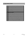
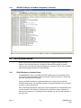
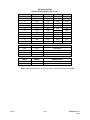
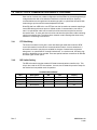
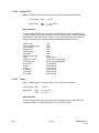
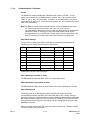
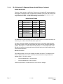
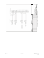
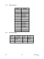
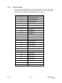
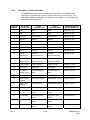
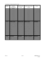
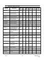
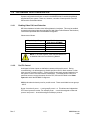
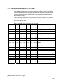
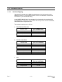
5.3
MACRO ERRORS
Macro errors are displayed as a warning message on the video monitors text overlay for
a period of two seconds following the error condition occurring. It is also recorded in a
text file called ERRORLOG that can be viewed in the MaxMon Error Log window or in the
Maxmon utility, together with a macro trail to help identify the cause of the macro error.
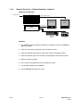
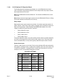
01
02
03
04
05
06
07
08
09
10
11
12
13
14
15
16
17
18
19
20
21
22
23
24
25
26
27
28
29
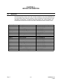
Rev. C
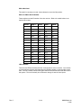
Macro Error Definition Table
Format error in extended command
Format error in conditional command
Unknown command in expression evaluation
Unknown command in update expression
Numeric variable range error
Scan sequence range error
External alarm range error
Auxiliary control output range error
Invalid numeric evaluation error
Macro timer range error
Macro timer command error
Macro timer period error
System macro range error
Unknown video output channel
Unknown video input source
Invalid external alarm control logic
Invalid auxiliary output control logic
Invalid camera disable logic
Invalid PTZ speed
Unknown system constant error
Unknown text message command error
Invalid operator sign used with commands
invalid keyboard identification number
Invalid alarm stack entry i.e.: not an alarm macro
Invalid alarm display group (1 Ù 50) only
Macro string exceeds 255 characters
Conditional statement missing closed brackets
Invalid real time clock time or date definition
Invalid video source command
5-4
HMXMU01018
10/06
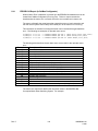
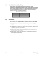
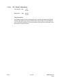
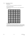
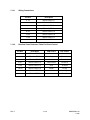
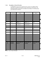
5.3 MACRO ERRORS, CONTINUED
30
31
32
33
34
35
36
37
38
39
40
41
42
43
44
45
46
47
48
49
50
51
52
53
Rev. C
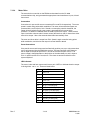
Macro Error Definition Table
String variable command format error
String variable range error
Unknown evaluate command for string
Too many nested do-while loops
Format error in do-while loop
Maximum loop cycles has been exceeded
Keyboard priority range error
Invalid keyboard identity for macro numeric input command
Invalid destination for keyboard macro numeric input command
Too many digits requested for keyboard macro numeric input
Invalid scan clear command
No dynamic macro timer available
User flag range error (0 Ù 8 only)
Keyboard operator range error (0 Ù 100 only)
User defined character range error, in direct comm port writes
Undefined comm port number, in direct comm port writes
Internal change network source
Internal change network source node command format error
Scan sequence entry number is out-of-range i.e.: greater than (99)
Error in command format received from a subrack/keyboard
Parity error in received data from a subrack/ keyboard
Range error in Blank Channel command (valid 0 - 3 only)
Unknown Special WORD command. eg <WARM-BOOT> etc.
Other errors detected during Cold/Warm Boot. Check ERRORLOG.
5-5
HMXMU01018
10/06
5.3.1
ERRORLOG Report (in SetMax Configurator)
When a Macro Error is detected, it is written into the ERRORLOG database that can be
viewed from SetMax Configurator (ErrorLog Tab). This error report contains the
time/date that the macro error occurred, the macro error number and a macro trail.
The macro trail details the actual event that caused the macro to begin execution and
lists the various system macro library lines called prior to the macro error occurring.
This information is essential in locating the actual macro command that generated the
error. The following are examples of reported macro errors.
27/NOV/96 17:39.31 -> ??MACRO ERROR #15 KB:1 (KB01:KI017,%040,%041,%042)
27/NOV/96 17:39.42 -> ??MACRO ERROR #51 KB:5 (KB05:AS104,%301,%050)
27/NOV/96 17:39.50 -> ??MACRO ERROR #14 KB:34 (KB34:TM001,%113,%114)
The following table describes the two-letter macro event code for the reported macro
error.
Event Code
AS
AF
VS
VF
CB
WB
KI
KR
PE
NT
LN
LB
SN
SF
UM
TM
DM
Description of Event
External alarm start macro
External alarm finish macro
Video input start macro
Video input finish macro
System cold boot macro
System warm boot macro
Keyboard key intercept macro (key-pressed)
Keyboard key intercept macro (key-released)
Keyboard post event macro (executed)
Network macro received from another MAXPRO-Net network node
local network macro (internal action request type)
local network macro (status broadcast type)
operator sign-on macro
operator sign-off macro
keyboard user macro
timed-event macro
Direct macro command from an external system (via highlevel)
The macro error report also details other important events in the MAXPRO-Net
Crosspoint Matrix Video Switching System. For example:
Rev. C
5-6
HMXMU01018
10/06
5.3.1
5.4
ERRORLOG Report (in SetMax Configurator), Continued
DATA STREAM TESTING
Some of the following sample fault-finding techniques suggest looking at the Data
Stream. There are many methods of viewing the data stream ranging from simple
indicator boxes, that will help diagnose wiring errors or breaks or loss of data, to RS232
data stream logging programs such as PATCH232.
5.4.1
RS232 Breakout or Indicator Boxes
The MAXPRO-Net® Server uses XON and XOFF signaling protocol and therefore does
not require hardware handshake signals to be wired. Only three (3) wires - TX Data, RX
Data and Signal ground are required.
Using your RS232 test box, even high-speed data can be seen clearly as the LED
indicators flash quickly. This indicates that data is being generated but does not indicate
its speed or other characteristics.
After connecting all equipment, ensure that a light is displayed on the Data Breakout Box
for each direction. This means the TX Data line is connected. If using a multimeter to
determine the transmit pin, its voltage should be between -9V and -15V with reference to
the ground pin.
Rev. C
5-7
HMXMU01018
10/06
5.4.2
PATCH232 Test Program
PATCH232 can assist in solving problems relating to speed, format and protocol as well
as being particularly useful for diagnosing intermittent problems.
System Requirements
MAXPRO-Net Server communicates with external devices and accepts commands from
external computers, keyboards, GUI’s, access control systems etc. An on-board VGA
chip-set is included for displaying system configuration and diagnostic software. One
PCI Bus 8 Port Serial RS-232 COM card is included, providing for communications
between external devices, such as matrix switching sub-racks, pan/tilt and dome
receivers and keyboards. Keyboard and mouse included.
In order to use PATCH232, you will require an IBM compatible computer with two serial
communications ports (COM1 & COM2), preferably a portable unit. A Hard Disk Drive is
recommended if the recorder function is going to be used. A variety of patch cords and
adapters are usually required.
Overview
PATCH232 is a very useful service tool as it allows you to look at the data being passed
down an RS-232 link. This enables you to evaluate the data and check that what data
you think should be appearing is actually there. It also allows you to see any data
corruption, which can be very hard to find if you are not able to see the data. Another
very useful feature is the ability to insert a command in either direction. PATCH232 has a
recording mode that allows it to act as a data logger. This feature is handy for any
intermittent problems as you can leave PATCH232 to record all data passed over the
link, to be examined at a later date.
Instructions for Use
PATCH232 can be used at either end of the link. To connect the laptop remove the
cable going to the MAXPRO-Net® Control Computer from the Subrack (RD-500 keyboard
or High-Level Interface) and connect it using any necessary adapters to COM2 on the
laptop. Then connect COM1 of the laptop to the communications port on the MAXPRONet® Control Computer using a NULL MODEM adapter or cable. When this is complete,
turn the power to the laptop ON and run 'PATCH232.EXE'. The program will then prompt
you for the required low level protocol, i.e. Baud rate (19200, 9600, 1200, 600, 300),
Parity (even, odd, none), Number of data bits (7 or 8) and the Number of stop bits (1 or
2).
The normal MAXPRO-Net® serial port settings are as follows:
•
Subracks, RD-530 Keyboards and High Level Interfaces
19200, E, 7, 1
•
RD-500 Keyboards
9600, E, 7, 1
These are indicative only, as most devices can be configured differently to suit the site.
Please check your documentation for the correct values if PATCH232 does not seem to
work.
Rev. C
5-8
HMXMU01018
10/06
5.4.2
PATCH232 Test Program, Continued
From MASTER to SLAVE Window:
This window displays all data received from COM1 (Master) and at the same time the
data is re-transmitted to the Slave via COM2. Any data manually sent from PATCH232 to
the Slave will also be displayed in this window.
From SLAVE to MASTER Window
This window displays all data received from COM2 (Slave) and at the same time retransmits the data to the Master via COM1. Any data sent from PATCH232 to the Master
will also be displayed in this window.
Comms Status Window: This window displays the current comms' and the recorder
status.
Commands
<ESC>
To return to DOS.
<M>
Send command to MASTER. Pressing the 'M' key enables you to enter a
string or command that will be sent to the MASTER. For example, you could
send to the MAXPRO-Net® Control Computer, the Subrack #1 reset
command (*1Z) which would cause the MAXPRO-Net® software to WARM
BOOT and update all subracks.
<S>
Send command to SLAVE. Pressing the 'S' key enables you to enter a
command that is sent to the SLAVE.
<R>
Recorder log ON/OFF. Pressing the 'R' key toggles the record status on and
off. When the record mode is enabled, all data received is time and date
stamped and recorded to files on the hard disk. Two files are created
MASTER.LOG that contains all data received from the MASTER (COM1),
and SLAVE.LOG that contains all data received from the SLAVE (COM2). If
the files already exist, PATCH232 will append them.
Internal Diagnostics
Additional Diagnostics are available from MaxMon. (See MaxMon Diagnostics Utility.)
The MaxMon Utility can display the following details simultaneously at runtime:
Rev. C
•
Received data,
•
Transmitted data
•
Macro Trails
•
Macro Execution sequence
•
Video Source Control Selection
•
Video Switch selections.
5-9
HMXMU01018
10/06
5.4.2
PATCH232 Test Program, Continued
In addition, MaxMon can act as a Remote system keyboard. Direct camera menu control
can be exercised from MaxMon.
MaxMon also provides recent system status (Configuration status,
Monitor/keyboard/operator relations.
These run-time diagnostics are particularly useful as they enable you to diagnose the
operations of the system while it is running. When some experience has been gained,
these facilities assist in rapid commissioning and debugging.
Rev. C
5-10
HMXMU01018
10/06
CHAPTER 6 :
MODULE INFORMATION
6.1
MODULES
The following table provides a list of the modules available for use with the MAXPRO-Net
Crosspoint Matrix Video Switching System, and the availability of Data Sheets and other
information. Configuration, connections, DIP switch settings, etc., where available, can
be obtained from the sources listed in the table. Modules are listed in numeric order.
Module ID
MX04 & MX08
MX18
RD85
RD89
RD105B
RD200
MX205
RD220
RD315
RD316
RD378E
RD400
HMX440
RD490
RD494
PT-719
PT-720
HMXPS9
Rev. C
Description
Multi-Port Serial Cards
Auto Changeover Unit
Video Switching
Video Verification / Loss
Subrack Controller
Text Inserter
Enhanced Text Inserter
Hidden Text Inserter
PTZ Controller
PTZ Controller
Site Receiver
Alarm Input Card
Relay Output Card
Universal Peripheral Interface
Resistive Ladder Interface
PTZ Dome (High Speed)
PTZ Dome (High Speed)
Subrack Power Supply
6-1
Information Location Key
DS, S&I, MSD, TS
DS, S&I, MSD, TS
S&I, MSD, TS
S&I, MSD, TS
DS, S&I, MSD, TS
S&I, MSD, TS
MSD,TS
MSD,TS
DS, S&I, MSD,TS
DS, S&I, MSD,TS
PSM,S&I,MSD,TS
DS, S&I, MSD,TS
DS, S&I, MSD, TS
DS, S&I, MSD, TS
DS, S&I, MSD, TS
PSM, S&I, MSD, TS
PSM, S&I, MSD, TS
S&I, MSD, TS
HMXMU01018
10/06
6.1 MODULES, CONTINUED
The information location keys are listed in the preferred order of access. Whilst it may be
easier to call Technical Support, this may not optimize your usage of Technical Support
Units. For further details, please refer to your Commissioning Manual.
Key
DS
S&I
TS
MSD
PSM
Rev. C
Information Location
Data Sheet (packed with product)
Service & Install Manual
Via Technical Support
From your DISTRIBUTOR
Product Specific Manual
6-2
HMXMU01018
10/06
CHAPTER 7:
DATA SHEETS
7.1
DATA SHEETS
The pages in this section are copies of the information supplied with each individual unit
as shipped. Due to improvements and new products, the information on these pages
may become incomplete. Please verify data sheets that are supplied with units are not of
a later revision to those in this section, before discarding.
Rev. C
ID
DESCRIPTION PAGE
MX08 & MX04
MULTI-PORT SERIAL CARDS
MX18
SYSTEM CONTROLLER AUTO CHANGEOVER
UNIT
RD85
VIDEO SELECTION MODULE (1 CH.)
RD89
VIDEO VERIFICATION CARD
RD105B
SUBRACK CONTROLLER
RD200
TEXT INSERTION MODULE
MX205
TEXT INSERTION MODULE (+ seconds)
RD315
PTZ CONTROLLER
RD316
PTZ CONTROLLER
RD378E
PTZ SITE RECEIVER – MULTI SPEED
RD379E
PTZ SITE RECEIVER – MULTI SPEED
RD400
ALARM INPUT CARD
MX440
RELAY OUTPUT CARD
RD490
REMOTE VCR CONTROL
RD494
RESISTIVE LADDER PROGRAMMABLE
PERIPHERAL INTERFACE MODULE
HEGS5300
ENHANCED KEYBOARD
HMXPS9
SYSTEM POWER SUPPLY
RD9021
I/O INTERFACE MODULE
HMX1676
TEXT INSERTION SUBRACK
7-1
HMXMU001018
10/06
Notes:
Rev. C
7-2
HMXMU001018
10/06
7.2
MX04 & MX08 MULTI-PORT SERIAL CARDS
The MX04/MX08 cards are used to provide multiple RS-232 serial communication ports
in MAX-1000 System Controllers. The MX04 and MX08 provide 4 ports and 8 ports
respectively. The boards plug into any available ISA expansion slot in the control
computer, with the maximum combination being two MX08 and one MX04 boards,
giving a total of 20 ports.
Note: This card is not used with MAXPRO-Net. MAXPRO-Net uses standard windows
PCA Serial Port expanders.
7.2.1
Switch Settings
Each board has a 4-way DIP switch. This sets the address for each port and is detailed
in the table below. Note that SW4 is not used. No two cards in any System Controller
should have the same switch settings.
MX08 Switch Settings
SW1
SW2
ON
ON
ON
ON
SW3
ON
OFF
(DEFAULT)
ON
ON
OFF
Rev. C
OFF
OFF
ON
ON
OFF
ON
PORT 1
PORT 2
PORT 3
PORT 4
PORT 5
PORT 6
PORT 7
PORT 8
$3F8~
$2F8~
$2B0~
$2B8~
$1A0~
$1A8~
$1B0~
$1B8~
$3FF
$2FF
$2B7
$2BF
$1A7
$1AF
$1B7
$1BF
$160~
$168~
$170~
$178~
$180~
$188~
$190~
$198~
$167
$16F
$177
$17F
$187
$18F
$197
$19F
$2A0~
$2A8~
$2B0~
$2B8~
$1A0~
$1A8~
$1B0~
$1B8~
$2A7
$2AF
$2B7
$2BF
$1A7
$1AF
$1B7
$1BF
$2F8~
$2A8~
$2B0~
$2B8~
$1A0~
$1A8~
$1B0~
$1B8~
$2FF
$2AF
$2B7
$2BF
$1A7
$1AF
$1B7
$1BF
$3F8~
$2F8~
$3E8~
$2E8~
$280~
$288~
$290~
$298~
$3FF
$2FF
$3EF
$2EF
$287
$28F
$297
$29F
7.2-1
HMXMU001018
10/06
7.2.1
Switch Settings, Continued
MX04 Switch Settings
SW1
SW2
SW3
PORT 1
PORT 2
PORT 3
PORT 4
ON
ON
ON
$3F8~
$2F8~
$2B0~
$2B8~
$3FF
$2FF
$2B7
$2BF
$160~
$168~
$170~
$178~
$167
$16F
$177
$17F
$2A0~
$2A8~
$2B0~
$2B8~
$2A7
$2AF
$2B7
$2BF
$2F8~
$2A8~
$2B0~
$2B8~
$2FF
$2AF
$2B7
$2BF
$1A0~
$1A8~
$1B0~
$1B8~
$1A7
$1AF
$1B7
$1BF
$180~
$188~
$190~
$198~
$187
$18F
$197
$19F
$3F8~
$2F8~
$3E8~
$2E8~
$3FF
$2FF
$3EF
$2EF
ON
ON
OFF
(DEFAULT)
ON
ON
OFF
OFF
OFF
7.2.2
OFF
OFF
ON
ON
OFF
ON
OFF
ON
OFF
ON
Jumper JP1
This jumper controls the IRQ number for port 1 interrupt. Setting the jumper in the top
position selects IRQ3 (default), and in the bottom position selects IRQ4. Selecting IRQ4
may be required in some high-level interface applications. Ports 2 to 8 (or ports 2 to 4
with the MX04) are fixed at interrupt IRQ3.
Rev. C
7.2-2
HMXMU001018
10/06
7.2.3
Interface Board
The MX04/ MX08 connects to the interface board via a 34-position ribbon cable.
Attach the ferrite clamp (part 840954-011) included in the expansion kit to the
34-position ribbon cable at the end closest to the interface card (the board with the RJ11
connectors).
The interface board is fixed inside the back panel of the control computer, and is fitted
with RJ11 connectors to allow easy connection to MAX-1000 subracks, keyboards, and
other MAX-1000 equipment. Pin connections from the RJ11 connectors are as follows:
RJ11 Socket (rear of System Controller)
Pin 1 – 12VDC
Pin 2 – N/C
Pin 3 – TX Data
Pin 4 – Signal GND
Pin 5 – Rx Data
Pin 6 – Power GND
Pin 6
Pin 1
The interface board provides fused 12VDC only at RJ11 connectors 3 and 4 (ports 3 & 4)
to power HEGS5300 and ULTRAKey keyboards.
NOTE: When D25 connectors are provided, (or fitted to a
System Controller), standard RS-232 pin allocations
apply (i.e. pin 2 = TX, pin 3 = RX, pin 7 = GND).
NOTE: When D25 connectors are fitted to a System
Controller, the keyboard power (HEGS5300) is provided
on port 4 (i.e. pin 13 = +12VDC, pin 25 = GND).
NOTE: A maximum of 2 keyboards can be powered
directly from a single interface board.
Rev. C
7.2-3
HMXMU001018
10/06
Notes:
Rev. C
7.2-4
HMXMU001018
10/06
7.3
MX18 SYSTEM CONTROLLER AUTO CHANGEOVER UNIT
The MX18 System Controller Auto Changeover Unit is used to combine two
MAXPRO-Net Servers to increase reliability, with automatic changeover in the event of a
System Controller failure. (MX-18 can also be used with MAX-1000.)
The MX18 is fitted with dual Power Supply monitored inputs for true redundancy
operation.
Serial port expansion is also provided for subrack or keyboard communications.
DIP SWITCH IDENTITY CODE SETTING – VERSION 2.xx FIRMWARE
Identity
Code
H70
H71
H72
H73
H74
H75
H76
H77
H78
H79
H80
H81
H82
H83
H84
H85
SW 1-1
SW 1-2
SW 1-3
SW 1-4
OFF
ON
OFF
ON
OFF
ON
OFF
ON
OFF
ON
OFF
ON
OFF
ON
OFF
ON
OFF
OFF
ON
ON
OFF
OFF
ON
ON
OFF
OFF
ON
ON
OFF
OFF
ON
ON
OFF
OFF
OFF
OFF
ON
ON
ON
ON
OFF
OFF
OFF
OFF
ON
ON
ON
ON
OFF
OFF
OFF
OFF
OFF
OFF
OFF
OFF
ON
ON
ON
ON
ON
ON
ON
ON
Data
Speed
19200 baud
9600 baud
1200 baud
SW 2-3
SW 2-4
OFF
OFF
ON
OFF
ON
OFF
Data
Format
8 bit
no parity
ON
7 bit
even parity
OFF
Pass
<Ack>
ON
Block
<Ack>
OFF
SW 2-2
ACK Filter
SW 2-1
Rev. C
7.3-1
HMXMU001018
10/06
7.3 MX18 SYSTEM CONTROLLER AUTO CHANGEOVER UNIT, CONTINUED
CAUTION: To avoid the MX18 indicating failure during
system startup, be sure to set the ‘All’ parameter in the
CTRL field of the Serial Communications Ports, for any
ports that are connected to a MX18.
The MX18 is designed to report various status information
regarding its operation. It simulates a RD400 alarm input
module located in pseudo-slot (0). In order for these
alarms to be generated, they must first be enabled. This
is done automatically by the MAX-1000 when the required
alarm status pseudo inputs are defined in the External
Alarm Input Table.
CAUTION: Alarm inversion is NOT supported. All alarms
must be defined as “N/O” type alarms. With the exception
of ALARM (1), all other alarms are enabled only for the
MX18 using the base ID code (i.e. H70).
ALARM 1. The MX18 CPU is operating correctly, to detect CPU fail.
This alarm is ACTIVATED 10 seconds after any RESET command, or 10 seconds
following cold-boot initialization.
ALARM 2. Master Computer Fail.
An alarm ACTIVE is generated when communications is lost with the MASTER
Computer. The alarm will CLEAR upon restoration of communications with the MASTER
computer.
ALARM 3. Standby Power Supply Lost.
An alarm ACTIVE is generated when the + 9VDC standby power supply falls below
approximately 6V. The alarm will CLEAR upon restoration of the standby power supply.
ALARM 4. Main Power Supply Lost.
An alarm ACTIVE is generated when the + 9VDC main power supply falls below
approximately 6V. The alarm will clear upon restoration of the main power supply.
ALARM 5. Slave Computer Fail.
An alarm ACTIVE is generated when communications is lost with the SLAVE Computer.
The alarm will CLEAR upon restoration of communications with the SLAVE computer.
ALARM 6. Master Selected Status.
An alarm ACTIVE is generated when the MASTER Computer is selected as the system
controller. The alarm will CLEAR if the SLAVE Computer is selected as the system
controller. This alarm is activated by Automatic & Manual selection changeover.
Rev. C
7.3-2
HMXMU001018
10/06
7.3 MX18 SYSTEM CONTROLLER AUTO CHANGEOVER UNIT, CONTINUED
ALARM 7. Slave Selected Status.
An alarm ACTIVE is generated when the SLAVE Computer is selected as the system
controller. The alarm will CLEAR if the MASTER computer is selected as the system
controller. This alarm is activated by Automatic & Manual selection changeover.
ALARM 8. Not defined.
The MAX PROTOCOL commands that the MX18 will recognize and respond to, are listed
below. It will only listen to commands from the currently selected MASTER or SLAVE
Computer. Commands from the non-selected one will be ignored.
“Z”
RESET command (RX/TX)
When a warm reset is received the MX18 only re-initializes the alarm states. No other
action or indication is given.
“X”
POLL command (RX/TX)
When the poll request command is received the MX18 will immediately generate the poll
answer sequences. This is used to satisfy the subrack polling mode (if in use).
“R”
READ command (TX)
When an enabled pseudo alarm changes state a read command sequence is generated
to represent the new status of that specific alarm. The format is identical to that
generated by a RD400 alarm input module.
Rev. C
7.3-3
HMXMU001018
10/06
Rev. C
MENU
OUT
MENU MENU
SLAVE MASTER
IN
IN
8
1
2
3 MX18 TX DATA
4 SIGNAL GROUND
5 MX18 RX DATA
6
PORTS 1 - 8
7
6
5
4
MASTER/SLAVE
3
2
1
SLAVE MASTER
1
2 MX18 TX DATA
3 SIGNAL GROUND
4 MX18 RX DATA
5
6
PINS
5,18
6,19
7,20
8,21
9,22
AUXILIARY
STANDBY POWER
INPUT
FAIL ALM
1
MULTIPORT - CPU
2
MASTER COMPUTER
3
STANDBY POWER
4
MAIN POWER
5
SLAVE COMPUTER
AUXILIARY
MAIN POWER
INPUT
POWER
NOT TO SCALE
1 +9V
2 GND
3
7.3 MX18 SYSTEM CONTROLLER AUTO CHANGEOVER UNIT, CONTINUED
7.3-4
HMXMU001018
10/06
7.3.1
Integration of MX18 System Controller with MAXPRO-Net and VideoBloX Matrix
Chassis
SLAVE MAXPRONET SERVER
MASTER MAXPRONET SERVER
COM 1
COM 2
COM 7
MAXPRO-Net
COM 1 - 9 DB9
Pin 2, RX
Pin 3, TX
Pin 5, GND
COM 8
COM 1
COM 2
COM 7
COM 8
MX18
RS232
RS232
MX18
DB9-RJ Connector
Provided by Honeywell
HVBMATPIT
MASTER RS232
DB9
Pin 3, RX
Pin 2, TX
Pin 5, GND
Ultrakey
Keyboard
Coiled Cable Supplied w/Ultrakey
(P/N 849518-0306)
HMX1600
MASTER
RS232
HVBMATPIT
DATA
SLAVE
RS422
HVBMATPIT DIP SWITCH SETTINGS
S1
1 - ON
2 - ON
3 - OF F
4 - OF F
5 - OF F
6 - OF F
7 - OF F
8 - ON
S2
1 - OF F
2 - OF F
3 - OF F
4 - OF F
5 - OF F
6 - OF F
7 - OF F
8 - OF F
S3
1 - OF F
2 - OF F
3 - ON
4 - OFF
5 - ON
6 - OFF
7 - OFF
8 - ON
RS422
Protocol 1
S1 set to Bossware input protocol at 19.2KB
S3 set to MAX-1000 Output protocol, reverse direction at 19.2KB
RS422
Protocol 2
HVB422FT16
RS422
PIT
Pin 1
Pin 2
Pin 3
Pin 4
Pin 5
Pin 6
Pin 7
Pin 8
Pin 9
WIRING
COMBO
-- Pin 4
-- Pin 3
-- Pin 2
-- Pin 1
-- Pin 5
-- Pin 6
-- Pin 7
-- Pin 8
-- Pin 9
To Matrix Switch Comms
VideoBloX Chassis
Set to Slave pin-out
DIP Switch S1
1 - On
2 - Off
3 - Off
4 - On
Note: If Pins 6 and 9 are connected as shown above,
the HVBMATPIT receives power from the HVB422FT16.
Do not attach an additional power supply to the
HVBMATPIT.
Rev. C
7.3-5
HMXMU001018
10/06
Notes:
Rev. C
7.3-6
HMXMU001018
10/06
7.4
RD85 VIDEO SELECTION MODULE
The RD85 video switching module is a single channel video switcher. It can select any
of the 32 video input signals (from the mother board video buss) or it's own cascade
video input (used when stacking multiple video switching subracks). All video switching
is vertical interval and in addition, a clamp-to-black period can be inserted at the
switching transition to HIDE any frame roll that may occur for unsynchronized video
signals. The video output from the RD85 module is fully DC restored for all video source
selections.
7.4.1
Operation
The RD85 video switching module is designed for use in any of the MAXPRO-Net video
switching subracks. One RD85 module is used for every channel of video switching
required (per subrack) or 32 inputs of full matrix.
The subrack control microprocessor (RD105B) manages the operation of every RD85
module used within the subrack. Video switching commands are sent from the
MAXPRO-Net system control computer to the subrack control microprocessor (RD105B).
The command is then decoded by the RD105B. The actual number of the video input
required is then written to the appropriate RD85 video switching module, causing the
new video source to be selected by that channel.
7.4.2
Vertical Interval Switching
When a new video input selection is written to the RD85 module, it is firstly stored in a
primary-latch. Note, this new video source number has not been selected yet. When the
next vertical interval sync pulse occurs (of the currently selected video signal), the new
video source number is transferred into a secondary-latch that actually makes the new
video source selection. The new video signal is now selected by the RD85 module and
available from its video output connector. This method of vertical interval switching
assumes that all video source signals are all vertically synchronized. If they are not, then
frame roll may still occur. Where no video signal was selected previously, the new video
source selection is made immediately.
Rev. C
7.4-1
HMXMU001018
10/06
7.4.3
Clamp-To-Black Video Switching Transition
When unsynchronized video sources are used in the video switching system a short
“CLAMP-TO-BLACK” period can be inserted at the video switching transition. This
allows any frame roll that may occur, to do so during the Clamp-to-Black period (i.e. the
roll is invisible), giving the illusion of synchronized video switching. The Clamp-to-Black
period is link selectable by LK2 on the RD85 module PCB. The link can be positioned in
eight positions to select a different period. The period is defined in numbers of video
fields to be clamped [i.e. link settings (fields)]:
7.4.4
Link Position
(fields)
Black Period
(milliseconds)
0
zero period
1
20Ms
2
40mS
4
80mS
8
160mS
16
320mS
32
640mS
64
1280mS
oo (+Audio)
Continuous black
Used As A Black Source
The Clamp-to-Black can be set to infinity by removing the Black Pause Link and placing
it in the Video position of LK1 (lower). In this position the module will output the Sync.
pulses only of the default camera selection. This can be used in a system as a Blank
(Black) Source. Input 1 of the subrack containing the Black Source card MUST have a
video source connected.
Rev. C
7.4-2
HMXMU001018
10/06
7.4.5
Used For Audio Switching
The Continuous Black Period is selected by removing the Black Pause Link and placing
it in the Audio position of LK1 (upper) when the RD85 is required to switch audio signals.
7.4.6
Diagnostic Video Connector
The front of the RD85 Module has a 3-pin “IDC” style connector with the video signal
present on the center pin and the ground on either of the two outer pins. The video on
this connector is the same as the output connector and may be used to diagnose the
system, from the front of the subrack rather than the rear.
7.4.7
Indicator
L1 illuminates when the RD85 Module has data written to it by the RD105B Subrack
Controller Module.
Rev. C
7.4-3
HMXMU001018
10/06
Notes:
Rev. C
7.4-4
HMXMU001018
10/06
7.5
RD89 Video Fail/Video Analysis Module
CAUTION: The following data refers to RD89 modules of
revision 5 hardware and later.
7.5.1
Operation
The RD89 Video Fail/Video Analysis Module is specifically designed to provide for
automated monitoring of video presence, level and quality. This functionality in
conjunction with the crosspoint matrix video switching capability provided by MAXPRONet® software allows a high level of automated and custom response to video source
exceptions. The RD89 monitors/analyzes video inputs (up to 32 maximum) on a
sequential basis. The typical monitoring period is 100ms per input and therefore, the
module can scan all 32 inputs in approximately 3 seconds. If less video inputs have
been configured for monitoring, the scan period will be reduced accordingly.
7.5.2
Installation
The RD89 may be installed in any 3RU video slot within MAXPRO-Net® subrack. The
module may be configured to monitor/analyze subrack bus video or an external input via
the subrack cascade input.
7.5.3
DIP Switch Definitions
SW1/1 Video Fail Mode / Video Analysis Mode
In the OFF position, the RD89 functions in the Video Fail detection mode and detects
lost video, low and high level video. In the ON position, the RD89 functions as a Video
Analyzer for automatic VCR playback analysis.
SW1/2 Video Bus / Cascade Select
In the OFF position, the video input to the RD89 is from the subrack video bus. In the ON
position, the video input is from the subrack cascade input.
Rev. C
7.5-1
HMXMU001018
10/06
7.5.3
DIP Switch Definitions, Continued
SW1/3 Low Level Video Enable / Video Analyzer Sensitivity 1
In the Video Fail mode of operation, this switch, if ON, enables reporting of lowlevel video alarms. In the OFF position, the low level video alarm reporting is
inhibited.
In the Video Analyzer mode, this switch in conjunction with SW1/4 provides for
selectable analyzer sensitivity (see table below).
SW1/4 High Level Video Enable / Video Analyzer Sensitivity 2
In the Video Fail mode of operation, this switch, if ON, enables reporting of high-level
video alarms. In the OFF position, the high level video alarm reporting is inhibited.
In the Video Analyzer mode, this switch in conjunction with SW1/3 provides for
selectable analyzer sensitivity (see table below).
7.5.4
7.5.5
Rev. C
Video Analyzer Sensitivity Selection
SW1/3
SW1/4
Sensitivity
OFF
OFF
LOW
ON
OFF
MID 1
OFF
ON
MID 2
ON
ON
HIGH
Indicators
L1 (RED)
Video Fail Mode – illuminated indicates that the video level is too high or
too low.
Video Analyser Mode – unused.
L2 (RED)
Video Fail Mode – illuminated indicates lost video.
Video Analyzer Mode – illuminated indicates poor quality or lost video.
L3 (GREEN)
Illuminates when the RD89 module is reading data from the subrack
data bus.
L4 (AMBER)
Illuminates when the RD89 module is writing to the subrack data bus.
7.5-2
HMXMU001018
10/06
7.6
RD105/105B Subrack Controller Module
Every subrack must have one RD105 (except the HMX32128 which requires a HMX128),
and every subrack requires an RS-232 port on the MAXPRO-Net Server or MX18. The
RD105 subrack control module is a slave microprocessor controller developed to
oversee the operation of an individual MAXPRO subrack (both video switching and I/O
types). It decodes all MAX protocol commands directed to the various modules located
in the subrack and performs the actual communication with the individual modules.
Video switching source selection, text insertions update, output control and alarm input
detection and set-up, are just some of the control tasks of the RD105 module. As it
plays an integral part of all system operations, the RD105 module would have to be
classed as the most important module in the MAXPRO-Net Crosspoint Matrix Video
Switching System.
Operation
The RD105 subrack control module is located in a specially allocated 'SCM' slot or slot
'0' of a MAXPRO subrack. Only one (1) RD105 module can be installed into a subrack,
and only into the 'SCM' slot position (top left slot). NEVER plug a RD105 module into
any other slot position as damage may occur.
The RD105 module communicates with the MAXPRO-Net Server through a full duplex
RS-232 asynchronous serial line. There is a separate RS-232 communication line for
each subrack in the system. Although the data content from the MAXPRO-Net Server to
subrack is generally the same for all subracks, an identity number is included into each
MAX protocol command to direct the command string to the required subrack. As each
RD105 module (i.e. each subrack) in a system application has its own unique identity
code number, the MAX protocol commands will only be accepted by the correct RD105
module.
Rev. C
7.6-1
HMXMU001018
10/06
Watch-Dog RESET
The design of the RD105 module is of a conventional nature with the exception of the
RESET circuit. Due to the overall importance of the system’s continuous operation, the
reset circuit is actually a Watch-Dog RESET circuit. Its function is as follows:
While the RD105 module is operating normally, a continually pulsing output is generated
by the on-board RD105 subrack management software. This pulsating signal is
monitored by the hardware circuit, being the watch-dog reset. If the pulsing output
should cease for more than 500msec, then the watch-dog reset circuit generates a new
hardware RESET to the microprocessor, restarting the module's management software
and attempts correcting the fault condition. Note, that the RD105 module also generates
a RESET command string that is sent to the MAXPRO-Net Server to force a reinitialization of the system.
RD105 LED Indicators
There are four LED indicators on the RD105 module. Their functions are as follows.
•
RESET: Whenever the RD105 module resets, this RED LED (L1) illuminates. It
actually displays the logic condition of the CPU-FAIL signal on the bus.
•
POWER: Whenever power is applied to the RD105 module, this GREEN LED
(L2) becomes on, and remains on until the power is removed.
•
SEL: This YELLOW LED (L3) indicator blinks when any slot in the subrack is
written to.
•
COMM: When a MAX protocol command is received by the RD105 module, this
YELLOW LED indicator (L4) blinks.
The 'SEL' and 'COMM' LED indicators are useful for following data communications
between the MAXPRO-Net Server and any module within a subrack.
Rev. C
7.6-2
HMXMU001018
10/06
DIP Switch Settings
Subrack Identity Number (001 to 799):
Units
Tens
Hundreds
S1-4
S1-8
S1-3
S1-7
S2-3
OFF
OFF
OFF
OFF
ON
ON
ON
ON
OFF
OFF
S1-2
S1-6
S2-2
OFF
OFF
ON
ON
OFF
OFF
ON
ON
OFF
OFF
S1-1
S1-5
S2-1
0
1
2
3
4
5
6
7
8
9
OFF
OFF
OFF
OFF
OFF
OFF
OFF
OFF
ON
ON
OFF
ON
OFF
ON
OFF
ON
OFF
ON
OFF
ON
SW2-7
OFF
OFF
ON
ON
SW2-6
OFF
ON
OFF
ON
BAUD RATE
19.2K BAUD
9600 BAUD
1200 BAUD
NOT USED
SW2-8
OFF
ON
MODE
RD-100
RD-104
DESCRIPTION
Normal subrack control
RD-6464 subrack - RD84 control
Note: SW2-4 and SW2-5 are not currently used. They should always be left OFF.
Rev. C
7.6-3
HMXMU001018
10/06
Notes:
Rev. C
7.6-4
HMXMU001018
10/06
7.7
RD200 TEXT INSERTION MODULE
The RD200 text inserter module is a single channel video-processing device used to
write up to five (5) lines of text information onto a video picture. The displayed text is
used to display labeling and feedback information to the system operators through the
video monitors. Information such as, camera identification, time/date display, monitor
number, current operator access and other system operation information can all be
displayed.
Some other applications for the RD200 text inserter modules are text labeling for VCR
recorded signals (recorded camera identity and time/date), display of alarm detection
information. Text can be displayed in a variety of modes including straight forward white
text over the video picture, white text with black shadowing, white text with a solid black
background for the entire text insertion window, reverse mode to exchange white and
black display. (i.e. give black text on a white background or shadow.), Normal or double
height text when bold displays are required. (e.g. alarm display, for VCR recording to
increase replay readability). A text display can be FLASHED to attract the system
operator's attention.
The positioning of the text on the screen is programmable from the
Setmax Configurator. No manual settings are done on the RD200 module itself, so
modules may be swapped and changed without worrying about resetting DIP switches
or trim pots for each application.
Operation
The RD200 text inserter module is designed for use in the MAXPRO-Net video switching
subrack and occupies one slot. It is capable of processing one video signal only; so
one RD200 module is needed for every video output channel requiring text insertion.
The cascade input (for each slot) is used as the video input to each RD200 module. The
processed video signal (video + text) is returned at the video output for that slot.
The usual implementation of a RD200 module is as follows. The video output from a
video-switching module (RD85) is patched to the cascade input of the allocated RD200
module. The resultant output from the RD200 module (video + text) is then taken away
as the actual video output for that video switching channel.
The slot allocation for the RD200 modules is totally variable (programmable at the time
of system configuration). As it occupies a slot position in the video switching subrack
(i.e. another possible video output channel position), it may sometimes be desirable to
locate the RD200 modules in a separate (stand-alone) video switching subrack. This all
depends on the video output channel requirements within a given system application.
The RD200 module has an in-built video distribution amplifier (VDA) to buffer the
processed video signal. The VDA gives a true 75-ohm drive capability at its output.
Rev. C
7.7-1
HMXMU001018
10/06
7.7 RD200 TEXT INSERTION MODULE, CONTINUED
Diagnostic Video Connector
The front of the RD200 has a 3-pin “IDC” style connector, with video present on the
centre pin and ground connected on the outer pins. The video on this connector is the
same as the output connector and may be used to diagnose the system from the front of
the subrack.
Indicators
The L1 located on the front of the RD200 illuminates when the RD200 is receiving data
from the RD105 / RD105B Subrack Controller Module.
Jumper Settings
The RD200 may have a settable link labeled LK2 consisting of three in-line pins or solder
points. The two end points will be marked “A” and “B”. If the system is operating on
Version 3 MAX-1000 software then link “B” to the centre point. If the system is operating
on Version 4 MAX-1000 software, then link “A” to the centre point. If the RD200 does not
have a LK2 jumper facility, then it is not suitable for use in a Version 4 system.
CAUTION: Only one 75-ohm video output is available
(for system use) from each RD200 module.
Rev. C
7.7-2
HMXMU001018
10/06
7.8
MX205 TEXT INSERTION MODULE
The MX205 Text Insertion Module is a single channel video-processing device used to
write up to five (5) lines of text information onto a video picture with the added benefit of
displaying seconds of time, unlike the RD200 Text Insertion Module.
NOTE: The MX205 is a Surface-Mount Device Module
that has been designed to supersede the previous RD205
Module.
In addition to test insertion, the MX205 Module provides Dynamic Cable Equalization up
to 700 meters. The displayed text is used to display labeling and feedback information
to the system operators through the video monitors. Information such as, camera
identification, time/date display, monitor number, current operator access and other
system operation information can all be displayed.
Some other applications for the MX205 Modules are; text labeling for VCR recorded
signals (recorded camera identity and time/date), and display of alarm detection
information. Text can be displayed in a variety of modes including straight forward white
text over the video picture, white text with black shadowing, white text with a solid black
background for the entire text insertion window, reverse mode to exchange white and
black display (i.e. give black text on a white background or shadow.), and normal or
double-height text when bold displays are required (e.g. alarm display, for VCR
recording to increase replay readability). A text display can also be FLASHED to attract
the system operator's attention.
The positioning of the text display on a screen and display mode required is
programmable from the MAX-1000 System Configuration Utility. No manual settings are
done on the MX205 Module.
Rev. C
7.8-1
HMXMU001018
10/06
7.8 MX205 TEXT INSERTION, CONTINUED
Module Operation
The MX205 Text Inserter Module is designed for use in a MAXPRO-Net video switching
subrack or a Pre-Text subrack and occupies one slot. It is capable of processing one
video signal only, so one MX205 Module is needed for every video output channel
requiring text insertion. The cascade input (for each slot) is used as the video input to
each MX205 Module. The processed video signal (video + text) is returned at the video
output for that slot.
The usual implementation of a MX205 Module is as follows. The video output from a
video-switching module (RD85) is patched to the cascade input of the allocated MX205
module. The resultant output from the MX205 Module (video + text) is then taken away
as the actual video output for that video switching channel.
The slot allocation for the MX205 Modules is totally variable (programmable at the time
of system configuration). As it occupies a slot position in the video switching subrack
(i.e. another possible video output channel position), it may sometimes be desirable to
locate the MX205 Modules in a separate (stand-alone) video switching subrack. This
depends on the video output channel requirements within a given system application.
The subrack control microprocessor (RD105) manages the operation of every MX205
text inserter module used within a subrack. Text insertion update commands are sent
from the MAXPRO-Net Server to the subrack control microprocessor (RD105). The
command is then decoded by the
RD105. The new text information is then written to the appropriate MX205 module.
LED Indicators
Rev. C
L1
Lights when MX205 Module is written to by the RD105 Subrack Controller
Module.
L2
Lights when MX205 Module writes to RD105 Subrack Controller Module.
7.8-2
HMXMU001018
10/06
7.9
RD315 PTZ SITE COMMUNICATIONS MODULE
The RD315 site communications module is used to communicate with theRD378E site
receivers, RD379 site receivers, and the RD380 Elbex Dome Site Receivers. The RD315
can control any combination of these site receivers for up to 16 PTZ sites, all connected
to the same two-wire network.
The RD315 uses a specially designed communications protocol allowing control data to
be transported at high speed over the two-wire network. All PTZ sites connected to the
two-wire network may be automatically monitored (polled). If any site should become
inactive (i.e. blown fuse, cut cables), then an alarm may be generated corresponding to
the detected site failure.
The RD315 module provides an RS-232 port. This allows for easy monitoring and
servicing of other two-wire networks and some special modes of communication
connection. Five LED indicators are provided on the front edge of the module:
L1
L2
L3
L4
L5
Green PTT Active
Red TX Failed
Green PTZ Comms
Yellow Reading Data From Subrack
Green Writing Data To Subrack.
The RD315 uses a Telecom approved line isolation transformer. This provides the
connection to the 600 ohm balanced two-wire network.
Note: Only standard twisted pair cable is required for the line connections up to 5 Km of
cable length.
The data format is true AUDIO to Line (0.3 to 5 kHz bandwidth) and can tolerate a total
line attenuation of up to 20dB. It supports 4-wire audio interface for connection to
simplex audio channels (microwave, optical fiber, etc.) The most important feature is that
all communications to/from the RD315 is through a common TWO-WIRE line providing
simultaneous control of up to 16 site receivers per two-wire network.
Rev. C
7.9-1
HMXMU001018
10/06
7.9 RD315 PTZ SITE COMMUNICATIONS MODULE, CONTINUED
Sites can be of wired, star or delta configuration and the RD315 is protected against high
voltage destruction with a line isolation transformer on the two wire lines. Optional
communications are through direct bit transfer type radio or optical fiber links at RS-232
levels using a synchronous bit stream depicted as AF-232.
Direct RS-232 from a RD-315 to one PTZ site can also be used over networks requiring a
normal RS-232 asynchronous protocol. Mixed modes of communication can also be
used. An optical fiber cable can be used for the first site and a two-wire line onto the
successive sites. Or a two-wire line to the first and then the optical fiber cable continuing
onto the successive sites. The site receiver manuals contain drawings that show many
methods of connecting to the RD-315.
7.9.1
PTZ Site Wiring
The normal connection to the site is a two-wire data type cable that carries the AFSK
control information from the RD-315 communications module. In some situations a 4
wire audio connection may be more suitable for the type of transmission equipment
being used. i.e. optical fiber AF channel bi-directional. In a 4-wire mode, link audio ringaround or feed-back can be avoided. There are special interface connections for RS-232
and other types of fiber optics.
7.9.2
DIP Switch Setting
The RD-315 module uses the standard CC-2000 communications controller chip. This
chip is also used on all PTZ site receivers. As such, the CC-2000 chip must be setup for
the desired and compatible mode of operation.
Communications Modes
SW1
1
2
3
4
Rev. C
Description
Mode Select
Destination
Poll Mode
Not Defined
ON
Master
Slave
Enable
-
7.9-2
OFF
Slave
Master
Disabled
-
Factory
ON
ON
ON
ON
HMXMU001018
10/06
7.9.3
Setting Audio Communication Link Points
Line Interface Link 2 wire 4 wire (LK1) selects the type of audio connection required for
site communications.
Linking <2w> = selects Balanced two-wire communications. Note: This is the Default
setting.
Linking <4w> = selects four-wire communications. Transmit data is through the linetransformer to a balanced two-wire and is from the normal two-wire connection pins.
One side of this can be connected to ground if required to make the circuit unbalanced.
Alternatively the un-balanced audio can come from (DB25 pin 6 audio) and (DB25 pin 19
ground). Receive audio is through the unbalanced input (DB25 pin 7 audio) and (DB25
pin 20 ground).
LEVEL POTS: These are factory set and should never need adjusting. However, on
long cable runs, an increase in levels may be used. Both pots increase with a clockwise
rotation. RV1 is receive level and RV2 is transmit level.
Line Interface Connector part of DB25 for the used slot.
Pin No
6
19
7
20
22-25
9-12
Description
Hi-Z Unbalanced TX audio OUTPUT
Hi-Z Unbalanced TX audio GROUND
Unbalanced RX audio INPUT
Unbalanced RX audio GROUND
Balanced 2-wire line (first wire) / 4-wire TX
Balanced 2-wire line (second wire) / 4 wire TX
NOTE: For normal system installations, the two-wire line
is connected across pins 22 and 9 of the D25 connector
corresponding to the slot position of the RD 315 module.
The UNBALANCED INPUT should not be wired more than
a few meters in length and must be shielded, as it is a
high impedance input.
The preferred connection point for 4-wire TX output is
from the line transformer, pins 22,9.
Pin No.
8
3
16, 21
Rev. C
Description
Receive Data (data to site)
Transmit Data (data from site)
Signal Ground
7.9-3
HMXMU001018
10/06
7.9.4
Direct RS-232 Control Or Data Testing
Direct connection can be made to the communication processor. RS-232
Communications can be used during testing to monitor the serial data traffic going out to
other PTZ sites. i.e. A laptop computer can be used to show the actual data information
as it is being transmitted. This port can also be used to communicate directly with a
single PTZ site receiver in a standard RS-232 format.
RS-232 Part of DB25 connector
Pin No
14,15
1
2
7.9.5
Description
RS-232 Signal Ground
RS-232 Receive Data
RS-232 Transmit Data
LED Indicators
L1 TT indicator. If ON, indicates that the PTT drive circuit is active. PTT active selects
transmit mode on a two-way radio.
L2 TX DATA indicator. Blinks when the valid data is being transmitted to a PTZ site
receiver.
L3 COMMS indicator. Remains ON for valid PTZ site communications. Switches OFF if
a polled PTZ site receiver does not answer.
L4 MODULE WRITE indicator. Blinks when the RD-315 module has been written to by
the RD105 subrack controller module.
L5 MODULE READ indicator. Blinks when the RD-315 module has been read by the
RD105 subrack controller module.
Rev. C
7.9-4
HMXMU001018
10/06
7.9.6
Subrack Slot D25 Connector Pin Allocations
Pin No
14,15
1
2
3
16
8
21
4
17
5
8
6
19
7
20
22-25
9-12
Rev. C
Description
RS-232 Signal Ground
RS-232 Receive Data
RS-232 Transmit Data
AF-232 Output
AF-232 Signal ground
AF-232 Input
AF-232 Signal ground
RX MUTE Sense INPUT
Rx MUTE Sense GROUND
PTT drive OUTPUT
PTT common (GROUND)
Hi-Z Unbalanced TX audio OUTPUT
Hi-Z Unbalanced TX audio GROUND
Unbalanced RX audio INPUT
Unbalanced RX audio GROUND
Balanced 2-wire line (first wire)/4w TX
Balanced 2-wire line (second wire)/4w TX
7.9-5
HMXMU001018
10/06
Notes:
Rev. C
7.9-6
HMXMU001018
10/06
7.10 RD316 MODULE - RS-422/485 PTZ SITE TRANSMITTER MODULE
7.10.1
General
The RD316 Communications Interface module is specifically designed to provide
protocol conversion and direct connection between the MAXPRO-Net system and third
party peripheral equipment. The RD316 allows for simplex, two wire half-duplex, and four
wire full duplex communication formats. Manchester, NRZ and NRZI encoding formats
are also supported. A switch-selectable transformer on board provides ground isolation
in these modes, if required.
7.10.2
Installation
The RD316 may be installed in any I/O slot within MAXPRO-Net subrack. All external
connections are via the subracks' DB25 connector for the appropriate slot. The following
table lists the connector pin-out details.
DB25 pin
3
4
5
6
7
8
9
10
11
12
16
17
18
19
20
21
22
23
24
25
Description
Ground
Ground
RX ‘B’
RX ‘B’
TX ‘B’
TX ‘B’
Transformer ‘B’
Transformer ‘B’
Transformer ‘B’
Transformer ‘B’
Ground
Ground
RX ‘A’
RX ‘A’
TX ‘A’
TX ‘A’
Transformer ‘A’
Transformer ‘A’
Transformer ‘A’
Transformer ‘A’
WARNING: Honeywell makes no representation and
offers no warranties as to the accuracy and/or suitability
of third party protocols and command formats. Such
protocols and command formats are based upon
information supplied to Honeywell by third party
manufacturers/suppliers at the time of implementation.
Rev. C
7.10-1
HMXMU001018
10/06
7.10.3
Indicators
The RD316 has three on board status indication LEDs. The functions of these are as
follows:
Upper LED (green) indicates the RD316 module is currently transmitting or receiving
data.
Center LED (yellow) indicates the RD316 module is writing data to the subrack.
Lower LED (green) indicates the RD316 module is reading data from the subrack.
NOTE: All three LEDs will flash continuously if an invalid
mode switch setting is selected.
7.10.4
DIP Switches
Both the operating mode of the RD316 and the transmission format are selectable via
the on-board DIP switches. Mode switch settings and the appropriate format switch
settings for the supported interface/protocol modes are detailed on the succeeding
pages. The general function of the format switches are as follows:
Rev. C
Position
Function when ON
SW1-1
Connect data output to isolation transformer
SW1-2
Connect terminating resistor across RX pair
SW1-3 & 4
Connect TX and RX pairs for two wire half duplex operation
7.10-2
HMXMU001018
10/06
7.10.5
Diamond Electronics - FastScan/SmartScan
Format switch SW1
1 - 4 OFF
Mode switch
1 - 8 OFF
SW2
Data Connection
FastScan/SmartScan receivers may be daisy chained or star connected with up to 16
receivers supported per RD316 module. Field cables may connect to DB25 pin pair 7(B)
and 20(A) or pin pair 8(B) and 21(A).
The auto-iris function supported by the receivers may be enabled by setting auxiliary
output 1 as defined in MAXPRO-Net to ON, any manual iris control function activated
thereafter will return the receiver to manual iris mode.
Using The Diamond Dome Camera Set-up Menu
Before You Start:
1. Is the Dome operational and can you control it? Pan/Tilt etc
2. Check Firmware version:
Controller Card
Firmware Version
RD316
V2.0 and above
HMX128
MX-308 Chip V1.06 and above
3. Equipment Required:
Rev. C
•
MAXPRO-Net System
•
Dome to be configured
•
MaxMon Utility
•
QWERTY Keyboard
•
Two monitors
7.10-3
HMXMU001018
10/06
7.10.5
Diamond Electronics - FastScan/SmartScan, Continued
Equipment Configuration
Diamond Dome
MAX Switching System
1
2
3
4
5
6
7
8
9
10 11 12 13 14 15
Operator Monitor Output
17 18 19 20 21 22 23 24 25 26 27 28 29 30 31 32
MAXPRO-Net CPU with
MaxMon
PC Monitor
Operator
Monitor
QWERTY
Keyboard
RD-500/530
VGA/RGB Output
(with Keyboard Emulation Tab)
Operation
1. Log QWERTY keyboard (System Keyboard) to the Operator monitor (See MaxMon
Manual for details).
2. Select the Dome being configured, from the Operator monitor.
3. Select the required Set-up menu from the Test monitor in the Maxmon menu.
4. Select the required option from the menu now displayed on the Operator monitor.
5. Make the required changes.
6. Esc to exit the configuration menu on the Operator monitor.
7. Log off System Keyboard from MaxMon
8. Use the MAXPRO-Net system as normal.
Rev. C
7.10-4
HMXMU001018
10/06
7.10.6
PELCO - Intercept/Legacy – AD Format
Format switch SW1
1 - 4 OFF
Mode switch
1, 3 - 8 OFF
2 ON
SW2
SW2
Data connection
Intercept/Legacy receivers may be connected with up to 16 receivers supported per RD316 module. Field cables may connect to DB25 pin pair 7(B) and 20(A) or pin pair 8(B)
and 21(A). Terminal A should connect to RX+, and terminal B should connect to RX-.
Note: Receiver addressing via the onboard DIP switch is true binary with a supported
range of 1 through 16 on each RD316. Data rate is 2400bps.
7.10.7
PELCO - Intercept/Legacy – Pelco 9750 Format
Format switch SW1
1 - 4 OFF
Mode switch
2 - 8 OFF
1 ON
SW2
SW2
Data connection
Intercept/Legacy receivers may be connected with up to 16 receivers supported per
RD316 module. Field cables may connect to DB25 pin pair 7(B) and 20(A) or pin pair
8(B) and 21(A). Terminal A should connect to RX+, and terminal B should connect to
RX-.
Note: Receiver addressing via the onboard DIP switch is true binary with a supported
range of 1 through 16 on each RD316. Data rate is 4800bps.
Note: Intercept and Legacy are trademarks of PELCO.
Rev. C
7.10-5
HMXMU001018
10/06
7.10.8
PELCO – Coaxitron Interface Format
Format switch SW1
1 - 4 OFF
Mode switch
2, 4, 6 - 8 OFF
1, 3, 5 ON
SW2
SW2
Note: Receiver addressing via the onboard DIP switch is true binary with a supported
range of 1 through 16 on each RD-316. Data rate is 4800bps.
7.10.9
Maxpro – RS-485 – Non Polling
Format switch SW1
1 - 4 OFF
Mode switch
2, 3, 5 - 8 OFF
1, 4 ON
SW2
SW2
Data connection
Maxpro RS-485 receivers may be connected with up to 16 receivers supported per
RD316 module. Field cables may connect to DB25 pin pair 7(B) and 20(A) or pin pair
8(B) and 21(A).
7.10.10
Maxpro – RS-485 – Polling
Format switch SW1
SW1
1, 2 OFF
3, 4 ON
Mode switch
1, 3, 5 - 8 OFF
2, 4 ON
SW2
SW2
Data connection
Maxpro RS-485 receivers may be connected with up to 16 receivers supported per RD316 module. Field cables may connect to DB25 pin pair 7(B) and 20(A) or pin pair 8(B)
and 21(A).
7.10.11
Vicon Standard
Format switch SW1
1 - 4 OFF
Mode switch
4 - 8 OFF
1 - 3 ON
SW2
SW2
Data connection
Vicon RS-485 receivers may be connected with up to 16 receivers supported per RD-316
module. Field cables may connect to DB25 pin pair 7(B) and 20(A) or pin pair 8(B) and
21(A).
Rev. C
7.10-6
HMXMU001018
10/06
7.10.12
Vicon Extended
Format switch SW1
1 - 4 OFF
Mode switch
1 - 3, 5 - 8 OFF
4 ON
SW2
SW2
Data connection
Vicon RS-485 receivers may be connected with up to 16 receivers supported per RD-316
module. Field cables may connect to DB25 pin pair 7(B) and 20(A) or pin pair 8(B) and
21(A).
7.10.13
Panasonic - WV-CS600/WV-RM70, WV-CS600A/WV-RM70, and WV-CSR600
Format switch SW1
1 - 4 OFF
Mode switch
1, 2, 4 - 8 OFF
3 ON
SW2
SW2
Data connection
Panasonic RS-485 receivers may be connected with up to 16 receivers supported per
RD316 module. Field cables may connect to DB25 pin pair 7(B) and 20(A) or pin pair
8(B) and 21(A).
The WV-RM70 should be set up at a data rate of 9600bps. All other settings should be
left at factory default values.
Note: It should be noted that some Panasonic receivers do not have preset view set
command capability via RS-485, and as such this function will not work. WVCS600A and later equipment supports this functionality.
Connection details from a Panasonic WV-CSR600 dome to the I/O slot of a subrack
(populated with a RD-316 module):
Rev. C
7.10-7
HMXMU001018
10/06
7.10.14
Panasonic - WV-CS850 Series
Format switch SW1
19.2Kbps
Mode switch
1 - 4 OFF
SW2
SW2
2, 4 - 8 OFF
1, 3 ON
SW2
SW2
1, 4 - 8 OFF
2, 3 ON
or
9600bps
Mode switch
Note: WV-CS850 Protocol was introduced in version 2.07 firmware. This version only
supports 19.2Kps. However, version 2.08 firmware and above does support
9600bps as well as 19.2Kbps.
Data connection
Panasonic RS-485 receivers may be connected with up to 16 receivers supported per
RD-316 module. Field cables may connect to DB25 pin pair 7(B) and 20(A) or pin pair
8(B) and 21(A). The WV-CS850 should be set for
4-wire duplex operation.
Connection details from a Panasonic WV-CSR600/CS850 dome to the I/O slot of a
subrack (populated with a RD-316 module) :-
Rev. C
7.10-8
HMXMU001018
10/06
7.10.15
American Dynamics
Two formats are implemented. 2 byte suitable for single speed receivers, e.g. AD 1689,
and a 4 byte version suitable for Cobra domes.
2 Byte Manchester
Format switch SW1
SW1
1 ON
2 - 4 OFF
Mode switch
SW2
SW2
1, 2, ON
3 - 8 OFF
Format switch SW1
SW1
1 ON
2 - 4 OFF
Mode switch
1, 2, 4 ON
3, 5 - 8 OFF
4 Byte
SW2
SW2
Data connection
AD Manchester receivers may be daisy chain connected with up to 16 receivers
supported per RD316 Module.
Field cables may connect to DB25 pin pairs 22(A) & 9(B), 23(A) & 10(B), 24(A) & 11(B),
25(A), & 12(B).
Pin (A) is equivalent to AD pin designation White.
7.10.16
Philips/Burle
Format switch SW1
1 - 4 OFF
Mode switch
1 - 4, 6 - 8 OFF
5 ON
SW2
SW2
Data connection
Up to 16 Philips/Burle RS-232 receivers may be connected via suitable RS-485
converter(s) to a RD316 Module. Data communication to the receivers is simplex
requiring only a two-wire circuit. The RS-485/232 converter(s) may connect to D25 pin
pair 7(B) and 20(A) or pin pair 8(B) and 21(A). The RD-316 utilizes a data rate of
9600bps, wiring distances and topology should be carefully planned to ensure reliable
data transfer.
Rev. C
7.10-9
HMXMU001018
10/06
7.10.17
Star/Chugai/Sanyo SMD12P, SMD20P, VCC9200P
Format switch SW1
1 - 4 OFF
Mode switch
1, 3, 4, 6 - 8 OFF
2, 5 ON
SW2
SW2
Data connection
Star/Chugai/Sanyo RS-485 receivers may be daisy chain or star connected with up to 16
receivers supported per RD-316 Module. Field cables may connect to DB25 pin pair
7(B) and 20(A) or pin pair 8(B) and 21(A).
7.10.18
Mark Mercer
Format switch SW1
1 - 4 OFF
Mode switch
1, 5 – 8 OFF
2, 3, 4 ON
SW2
SW2
Data connection
Mark Mercer RS-485 receivers may be daisy chain or star connected with up to 16
receivers supported per RD-316 Module. Field cables may connect to DB25 pin pair
7(B) and 20(A) or pin pair 8(B) and 21(A).
7.10.19
Videv
Format switch SW1
1 - 4 OFF
Mode switch
5 – 8 OFF
1 – 4 ON
SW2
SW2
Data connection
Videv RS-485 receivers may be daisy chain or star connected with up to 16 receivers
supported per RD-316 Module. Field cables may connect to DB25 pin pair 7(B) and
20(A) or pin pair 8(B) and 21(A).
7.10.20
VCL
Format switch SW1
1 - 4 OFF
Mode switch
2 – 4, 6 – 8 OFF
1, 5 ON
SW2
SW2
Data connection
VCL RS-485 receivers may be daisy chain or star connected with up to 16 receivers
supported per RD-316 Module. Field cables may connect to DB25 pin pair 7(B) and
20(A) or pin pair 8(B) and 21(A).
Rev. C
7.10-10
HMXMU001018
10/06
7.10.21
SpeedDome
Format switch SW1
1 - 4 OFF
Mode switch
2, 5 – 8 OFF
1, 3, 4 ON
SW2
SW2
Data connection
Speedome RS-485 receivers may be daisy chain or star connected with up to 16
receivers supported per RD-316 Module. Field cables may connect to DB25 pin pair
7(B) and 20(A) or pin pair 8(B) and 21(A).
7.10.22
Kalatel
Format switch SW1
1 - 4 OFF
Mode switch
3, 4, 6 – 8 OFF
1, 2, 5 ON
SW2
SW2
Data connection
Kalatel RS-485 protocol converters may be directly connected with up to 16 receivers
supported per RD316 Module. Converter cables may connect to DB25 pin pair 7(B) and
20(A) or pin pair 8(B) and 21(A). Tours 1-4 (where supported on Kalatel product) may be
activated through use of auxiliary outputs 5-8. Auxiliary output 2 is mapped to the auto
focus function.
Note: A Kalatel protocol converter must be used to convert the protocol to RS485 format.
One type is the KTD-93-1.
7.10.23
Baxall
Format switch SW1
1 - 4 OFF
Mode switch
1, 2, 4, 6 – 8 OFF
3, 5 ON
SW2
SW2
Data connection
Baxall RS-485 receivers may be daisy chain or star connected with up to 16 receivers
supported per RD316 Module. Field cables may connect to DB25 pin pair 7(B) and
20(A) or pin pair 8(B) and 21(A).
Rev. C
7.10-11
HMXMU001018
10/06
7.10.24
Bocom
Format switch SW1
SW1
2 - 4 OFF
1 ON
Mode switch
1, 2, 5 – 8 OFF
3, 4 ON
SW2
SW2
Data connection
Bocom Manchester receivers may be daisy chain connected with up to 16 receivers
supported per RD-316 Module. Field cables may connect to DB25 pin pairs 22(A) and
9(B), 23(A) and 10(B), 24(A) and 11(B), 25(A) and 12(B).
7.10.25
Ultrak KX Series Multiplexors
Format switch SW1
1 - 4 OFF
Mode switch
4, 6 – 8 OFF
1 - 3, 5 ON
SW2
SW2
Data connection
Ultrak multiplexers may be daisy chain connected with up to 16 units supported per
RD316 module. Multiplexer data terminal RXA connects to DB25 pin 20 or 21, data
terminal RXB to DB25 pin 7 or 8.
The list of supported functions is as follows:
Function No.
1
2
3
4
5
6
7
8
9
10
11
12
13
14
15
16
17
18
19
Rev. C
Multiplexer Function
Camera 1
Camera 2
Camera 3
Camera 4
Camera 5
Camera 6
Camera 7
Camera 8
Camera 9
Camera 10
Camera 11
Camera 12
Camera 13
Camera 14
Camera 15
Camera 16
Full screen
2x2 display mode
2x3 display mode
7.10-12
HMXMU001018
10/06
7.10.25
Rev. C
Ultrak KX Series Multiplexors, Continued
Function No.
Multiplexer Function
20
Set
21
4x4 display mode
22
Zoom
23
Select
24
Live record
25
VCR
26
Sequence
27
Hold (freeze)
28
Up arrow
29
Down arrow
30
Left arrow
31
Right arrow
32
Menu
7.10-13
HMXMU001018
10/06
7.10.26
Ranger FLIR
Note: The Ranger FLIR protocol is effective from version 2.08 firmware onwards
Format switch SW1
1 - 4 OFF
Mode switch
1 - 3, 6 - 8 OFF
4, 5 ON
SW2
SW2
Data connection
A single Ranger FLIR camera is supported by each RD316 module. Field cables may
connect to DB25 pin pair 7(B) and 20(A) or pin pair 8(B) and 21(A). The data rate/frame
specification is 19k2, 8 data bits, no parity, 1 stop bit. The special functions within the
Ranger FLIR camera are mapped to the following MAXPRO-Net® functions:
power on/off
auto brightness toggle
power standby
reticle on/off
polarity toggle
calibration
video overlay toggle
home
brightness control
contrast control
as set node
as start
as stop
as rate 400
as rate 600
as rate 800
7.10.27
aux1
aux2
aux3
aux4
aux5
aux6
aux7
preset call 0
preset calls 71-79 (fff-000)
preset calls 81-89 (fff-000)
preset call 91
preset call 92
preset call 93
preset call 94
preset call 95
preset call 96
Elbex
Note: The Elbex protocol is effective from version 2.10 firmware and later.
Format switch SW1
1 - 4 OFF
Mode switch
1, 3, 6 – 8 OFF
2, 4, 5 ON
SW2
SW2
Data connection
One Elbex RS-422 receiver may be connected per RD316 Module. Field cables may
connect to DB25 pin pair 7(B) and 20(A) or pin pair 8(B) and 21(A).
Rev. C
7.10-14
HMXMU001018
10/06
7.10.28
Tracam
Note: The Tracam protocol is effective from version 2.10 firmware onwards
Format switch SW1
1 - 4 OFF
Mode switch
3, 6 - 8 OFF
1, 2, 4, 5 ON
SW2
SW2
Data connection
Tracam RS-485 receivers may be daisy chain or star connected with up to 16 receivers
supported per RD316 Module. Field cables may connect to DB25 pin pair 7(B) and
20(A) or pin pair 8(B) and 21(A).
Notes:
7.10.29
•
Auxiliary Output 1 is used for the “Drive Forward “ command.
•
Auxiliary Output 2 is used for the “Drive Reverse” command.
JVC
Note: The JVC protocol is effective from version 2.10 firmware onwards
Format switch SW1
1 - 4 OFF
Mode switch
1, 2, 6 – 8 OFF
3, 4, 5 ON
SW2
SW2
Data connection
JVC RS-485 receivers may be daisy chain or star connected with up to 16 receivers
supported per RD316 Module. Field cables may connect to DB25 pin pair 7(B) and
20(A) or pin pair 8(B) and 21(A).
7.10.30
VST – RS-485 – Unidirectional
Note: The VST Unidirectional and bi-directional protocol is effective from version 2.15
firmware onwards.
Format switch SW1
1-4 OFF
Mode switch
1,6-8 OFF
2-5 ON
SW2
Data Connection
VST RS-485 receivers may be connected with up to 16 receivers supported per RD-316
module. Field cables may connect to DB25 pin pair 7(B) and 20(A) or pin pair 8(B) and
21(A).
Rev. C
7.10-15
HMXMU001018
10/06
7.10.31
VST – RS-485 – Bidirectional
Format switch SW1
1 OFF
2-4 ON
Mode switch
6-8 OFF
1-5 ON
SW2
Data Connection
VST RS-485 receivers may be connected with up to 16 receivers supported per RD-316
module. Field cables may connect to DB25 pin pair 7(B) and 20(A) or pin pair 8(B) and
21(A). The RD-316 will report PTZ site communication failure alarms and the status of the
alarm inputs on the VST receiver.
Rev. C
7.10-16
HMXMU001018
10/06
7.11 RD378E PTZ SITE RECEIVER
7.11.1
Features
The RD378 is an intelligent pan/tilt/lens controller for use at a remote camera site. Its
primary function is to operate the pan/tilt unit and zoom/focus lens controls.
Features include:
•
All communication to/from the RD378 site receiver is via a common two-wire line
providing simultaneous control of up to 16 site receivers per network. All data traffic
is managed by a RD315 two-wire transmitter module located in the equipment
subrack. Sites can be wired star or delta configuration and all sites are protected
against high voltage destruction with line isolation transformers on the two-wire line.
•
Capable of controlling any 24V DC pan/tilt unit at variable speeds and the lens
functions at two speeds.
•
Capable of retaining and subsequent re-positioning of up to 100 separate PTZ
views (presets).
•
When a view is selected, the pan tilt unit slows down as the required position is
approached.
•
Rev. C
Pan and tilt speeds vary with the zoom position of the lens.
•
A site tamper alarm input for securing the control cabinet, the alarm being sent
to the main MAXPRO-Net Server.
•
Communication options including synchronous bit stream at RS-232 levels
known as AF-232.
•
Direct RS-232 from a RD315 control card to one RD378 over networks where
normal RS-232 asynchronous protocol is required.
•
Mixed modes of communication can also be used. Fiber can be used to the first
site and then the two-wire line to the successive sites. Or perhaps two-wire to the
first site, and then fiber continuing to successive sites.
•
If the optional I/O expansion board (IO378) is fitted, then an additional seven
direct contact or current-loop sensing alarm inputs are available. The board also
provides eight separate relay output contacts, and an iris output for control of
motorized manual iris lenses.
7.11-1
HMXMU001018
10/06
7.11.2
Power Supply
The site receiver is supplied with AC mains power via the IEC connector mounted on the
PCB support bracket. This connector contains fuses, rated at 2A (@220VAC), and a
power filter. The IEC socket is connected under the support bracket to the toroidal
transformer primary. The transformer secondaries provide the following voltages to the
site receiver and have the associated fuses installed.
•
2 × 20V/5A via PL17 and PL18. F1 and F2 are rated at 5A. With the fuses in
place, the resulting unregulated ±28V DC will light LED’s L18 and L19. Used for
pan/tilt motor drive.
•
2 × 10.5V/2A via PL19 and PL20. F3 and F4 are rated at 2A. With the fuses in
place the resulting unregulated ±12V DC will light LED’s L2 and L3, and the
regulated 5V will light L1. Used to provide power for lens drive, 12V DC camera
power, and to supply the microcontrollers and associated circuits with regulated 5V.
•
1 × 24V/1A via PL2. F5 is rated at 1A. With the fuse in place LED L20 will light.
Used for AC camera power.
The 24V used to power an AC camera is output from the board at PL2. This supply is
isolated above ground. Alternatively, if a 12V DC camera is used, power is supplied
from PL1.
7.11.3
Communications
The RD378 site receiver communications are controlled by the CC-2000 micro-controller.
This section details the switch and jumper settings needed for the required mode of
communications.
Balanced TWO wire audio
The normal connection to the site receiver is a two-wire type cable that carries AFSK
control information from a RD-315 communications module. For this mode of operation,
the cable is connected into PL4, and LK6 must be in position “2W”. In addition, the LK2
must have jumpers to link “A→B” and “C→D” to link the communications processor to
the motor control processor. (Factory default).
FOUR wire audio
In some situations, a 4-wire audio connection may be more suitable. For example, when
an optical fiber AF channel is being used. The receive data is an unbalanced input at
PL3, while the transmit data is via a balanced two-wire at PL4. Audio sing around or
feedback can be avoided using this type of connection. The receive data cable should
not be wired further than a few meters and must be shielded as it is a high impedance
input. LK6 must be in position “4W”. In addition, the LK2 must have jumpers to link
“A→B” and “C→D” to link the communications processor to the motor control
processor.
CAUTION: The UNBAL-INPUT should not be wired
further than a few meters and must be shielded, as it is a
high impedance input.
Rev. C
7.11-2
HMXMU001018
10/06
7.11.3
Communications, Continued
AF-232
The RD378 also supports AFSK data at RS-232 levels, known as AF-232. For this
format use connector PL7, and LK6 must be in position “2W”. LK1 is used to select
“Echo on” (B) or “Echo off” (A) for data. In Position “A” the site receiver’s own data is
transmitted in AF-232 format. This is also sent in position “B”, but in addition the receive
data is also transmitted.
Note: The RD315 communications modules used to control the RD378 have a similar
link, and only one end can be used in the “echo on” mode. AF-232
communications contain full protocol for multi drop applications and is suitable for
optical fiber TX/RX. A multi drop ring loop fiber data system can be used to
communicate with up to 16 PTZ sites. Another option is to run optical fiber to the
first PTZ site and then normal 2-wire connection continues onto other sites.
SW2 Switch Settings
The use of the communications DIP switch SW2 is summarized in the table below.
Following is more details of the functions of each switch.
SW2
DESCRIPTION
ON
OFF
FACTORY
1
Mode Select
Master
Slave
OFF
2
Destination
Slave
Master
OFF
3
Poll Mode
Enabled
Disabled
ON
4
Not Used
5
Site ID No
Ref table page 8
6
Site ID No
Ref table page 8
7
Site ID No
Ref table page 8
8
Site ID No
Ref table page 8
*ON
*SW2-4 MUST be set to the ON position.
SW2-1 Mode Select (master or slave)
The RD-378 should have this switch set to off to select slave mode.
SW2-2 Destination Type (master or slave)
The RD-378 should always have this switch set to off to select a destination of master.
SW2-3 Polling mode
The polling mode on all RD-378 site receivers and RD-315 control card on the
communications network should be set to the same (ON or OFF). Usually, polling is
switched ON and in this mode the RD-315 control module will sequentially communicate
with all known slave locations (PTZ site receivers) in the network on a continuous basis.
If the RD-378 does not respond to this polling, then this change will be reported to the
MAXPRO-Net system.
Polling is usually only switched OFF when the communications link is limited to simplex
only and no return data is expected.
Rev. C
7.11-3
HMXMU001018
10/06
7.11.3
Communications, Continued
SW2-4 Not Used
This switch is currently not used. It must always be set to the ON position.
SW2-5 to SW2-8 Site ID Number
These switches set the ID number of the site receiver. Refer to the table below to set
required ID number.
SITE ID
SW2-5
SW2-6
SW2-7
SW2-8
1
OFF
ON
ON
ON
2
ON
OFF
ON
ON
3
OFF
OFF
ON
ON
4
ON
ON
OFF
ON
5
OFF
ON
OFF
ON
6
ON
OFF
OFF
ON
7
OFF
OFF
OFF
ON
8
ON
ON
ON
OFF
9
OFF
ON
ON
OFF
10
ON
OFF
ON
OFF
11
OFF
OFF
ON
OFF
12
ON
ON
OFF
OFF
13
OFF
ON
OFF
OFF
14
ON
OFF
OFF
OFF
15
OFF
OFF
OFF
OFF
16
ON
ON
ON
ON
LED Indicators
There are two LEDs associated with the communications micro-controller. L4 is the site
communications indicator and lights when the RD-378 is polled or receives valid control
data. L5 is the TX data indicator and lights when the RD-378 transmits valid data back to
the system. This would usually be to indicate a change of state of alarm inputs.
Rev. C
7.11-4
HMXMU001018
10/06
7.11.4
Motor Drive
The second microcontroller on the RD-378 receives data from the CC-2000
communications chip, and generates the appropriate control waveforms for pan, tilt and
lens motors.
Connections
Connections for pan and tilt motors are made at PL16 and PL15 respectively. The motor
speed is varied using pulse-width modulation. The slowest speed generates a waveform
with mark space ratio of 1:9, whilst the maximum speed generates 10:0 (i.e. the DC level
of ±28V). A brake output is also provided to release the motor brakes as the motor drive
waveform starts, and to re-apply the brakes when a halt command is received.
The motor drive and brake outputs are protected with a current limit of 5A. Should a
current spike pass this threshold, the output drive will switch off until a new output is
generated from the motor drive processor. In addition re-settable fuses are used to
protect the output. These become open circuit after a few seconds if excess current (but
less than 5A) is drawn from either motor drive output. After a few seconds these fuses
automatically reset.
The zoom and focus drive is output from PL9. Speed is again controlled using pulsewidth modulation, and this time the output is current limited to 80mA.
Preset Connections
If the pan/tilt motors and lenses used are fitted with position pots, up to 100 preset views
can be programmed into the RD-378 site receiver. The board provides a 5V reference
that is output to the pan/tilt pots at PL12, and to the focus/zoom pots at PL14. The
return voltage is then dependant on the position of the associated pot, and is input at
PL11 for pan/tilt and PL13 for focus/zoom. The views are set and recalled from the
system keyboard.
Rev. C
7.11-5
HMXMU001018
10/06
7.11.4
Motor Drive, Continued
LED Indicators
The motor, brake and lens outputs each have a pair of LEDs to indicate when the output
is driving either +ve or –ve. These are listed below.
LED
INDICATION
L6
Focus –ve
L7
Focus +ve
L8
Zoom –ve
L9
Zoom +ve
L10
Tilt –ve
L11
Tilt +ve
L12
Tilt Brake –ve
L13
Tilt Brake +ve
L14
Pan –ve
L15
Pan +ve
L16
Pan Brake –ve
L17
Pan Brake +ve
SW3 Switch Settings
The use of the motor drive switch SW3 is summarized in the table below. Following is a
more detailed description of the use of each switch.
SW3
DESCRIPTION
ON
OFF
FACTORY
1
Lens Voltage
6 Volt
12 Volt
ON
2
Privacy Zones
Enabled
Disabled
OFF
3
Auto Home
Enabled
Disabled
OFF
4
Pan/Tilt inversion
Inverted
Normal
ON
5
Focus/Zoom inversion
Inverted
Normal
OFF
6
I/O fitted
Enabled
Disabled
OFF
7
Speed 1
Ref to table
8
Speed 2
Ref to table
SW3-1 Lens Voltage
This switch sets the voltage required to control zoom, focus and manual iris on the
camera lens.
SW3-2 Privacy Zones
Privacy Zones. When switched on privacy zones are enabled.
Rev. C
7.11-6
HMXMU001018
10/06
7.11.4
Motor Drive, Continued
SW3-3 Auto Home
If this option is enabled, the PTZ will return to the preset position of view 0 after one
minute of no operation. Note that View 0 must be set before this function can operate.
SW3-4 Pan/Tilt Inversion
Allows the camera to be invert-mounted on the pan/tilt unit. Setting this switch ON will
reverse pan left/right and tilt up/down outputs from the RD-378, so that the camera can
be invert mounted, yet maintaining the wiring connections as per connection data.
SW3-5 Focus/Zoom Inversion
Manufacturers of lenses vary the use of +ve or –ve for in/out lens functions. This switch
is set to ensure the button function on the keyboard matches the actual operation
performed. This must be set correctly for the pan/tilt dynamic speed control from zoom
position to operate.
SW3-6 I/O Fitted
If the optional IO-378 board is fitted, then this switch must be switched ON. This allows
for seven additional alarm inputs and eight voltage free contact control outputs to
operate at the site as well as manual iris control.
SW3-7 and SW3-8 Speed Control
These switches are set depending on the type of pan/tilt unit being used. Their use is
described in the following table.
Rev. C
DESCRIPTION
SW3-7
SW3-8
STANDARD DC PTZ (Less than 40° /sec)
Full variable speed from analogue joystick, and auto two
speed (medium/fastest) from normal joystick. Graded pan/tilt
speed depending on lens zoom.
STANDARD DC PTZ (Less than 40° /sec)
Full variable speed from analogue joystick, and auto two
speed (medium/fastest) from normal joystick. Graded P/T
speed depending on zoom in position. Additional
Step/pause/run allows small increments of manual position
placement.
HIGH SPEED DC PTZ (Greater than 40° /sec, i.e. Fast
domes)
Full variable speed from analogue joystick, and auto two
speed (slowest/medium) from normal joystick. Graded
pan/tilt speed depending on lens zoom. Includes fine position
incremental placement of view calls.
HIGH SPEED DC PTZ (Greater than 40° /sec i.e. Fast domes)
Full variable speed from analogue joystick, and auto two
speed (slowest/medium) from normal joystick. Graded P/T
speed depending on zoom in position. Includes fine position
incremental placement of view calls and Step/pause/run for
small increments of manual position placement.
OFF
OFF
ON
OFF
OFF
ON
ON
ON
7.11-7
HMXMU001018
10/06
7.11.5
Motor Time Out
For all types of pan/tilt drives a motor time-out exists in software, i.e. should a pan/tilt run
to the end stop and the limit switch not shut the unit off, the software will stop the drive
after a period of four (4) minutes for any direction.
7.11.6
Tamper Alarm Input
The tamper alarm input can be used to secure the control cabinet and/or the camera
housing. The connections are made at PL10, and an open circuit between the two
terminals indicates an alarm condition. This will be detected by the motor control microcontroller, which will pass a message to the CC-2000 communications controller. This in
turn sends a message to the MAXPRO-Net Server.
7.11.7
Installation Notes
After all connections are made and the dip switches are set, the pan/tilt unit must be
manually controlled and the limit switches on the pan and tilt functions set. This is done
inside the pan/tilt unit itself and is not a site receiver function. With the limit switches set
the unit must be driven from stop to stop in every direction to allow the preset pots to
clutch into the correct position.
After all these mechanical and electrical settings have been done, press the initialize
button labeled SW1. The PTZ will then go through an initializing phase that operates all
the PTZ functions. This allows the site receiver to measure the direction of voltage
tracking for the presets and make auto reversals if required. If the site detects presets,
then the lens will track “fully zoom in” and “fully zoom out” then return to the spot it was
set at previously. This is to range the zoom for auto speed control, and this auto set-up
may take up to 10 seconds.
CAUTION: All directional control settings and lens
controls must be set and tested to be correct from one of
the system keyboards prior to this final RESET being
pressed. i.e. SW3-4 and SW3-5 must be set correctly.
7.11.8
Suitable cable sizing for PTZ heads when connecting to Site Receivers
As it is not unusual for Pan-Tilt heads to operate on relatively high current, it is imperative
that cable with adequate conductor size is installed between the PTZ site receiver and
the PTZ head.
The following table indicates the recommended cable conductor size based on cable
feed distance.
Rev. C
Cable Feed
Distance
Cross Sectional Area
of Conductor
5m
1.0mm (17 AWG)
10m
1.0mm (17 AWG)
15m
1.5mm (15 AWG)
20m
1.5mm (15 AWG)
30m
2.5mm (10 AWG)
7.11-8
HMXMU001018
10/06
7.11.9
RD378 PRIVACY ZONES
Introduction
Privacy zones are a method of restricting operator access of pan, tilt and zoom
operations. They allow supervisors to define areas that surveillance operators can and
cannot view. For example in residential areas, it would not be suitable to allow operators
to zoom into windows etc.
With the RD-378 site receiver (firmware V2.00 and above) privacy zones can be defined
by setting views from the operator keyboard. In this way they can be easily defined and
changed by supervisors as required.
To enable privacy zones on the RD-378, set DIP switch SW3-2 ON.
CAUTION: When using the IO-378 module, the Privacy
Zones option is not available.
Setting Privacy Zones
The RD-378 can have up to 5 privacy zones defined at any time. The zones are defined
by setting views 90 through 99. For the first zone (privacy zone 1) views 90 and 91
define the “window” that excludes the operator from entering. Privacy zone 2 is defined
by views 92 and 93 etc. See diagram below.
View 90
Privacy
Zone 1
View 91
To set an effective privacy zone, the following procedure is followed.
4. Set the zoom to the position required.
5. Using the keyboard move the pan/tilt so the bottom left corner of the required
privacy zone is at the very top right corner of the screen.
6. At this position set view 90.
7. Move the pan/tilt so the top right corner of the required privacy zone is at the very
bottom left corner of the screen.
8. At this position set view 91.
The first privacy zone has now been set and will stop the operator panning or tilting into
the area.
Rev. C
7.11-9
HMXMU001018
10/06
7.11.9
RD378 Privacy Zones, Continued
When setting view 90 position, the zoom position is stored. If the operator then zooms
out from this position the privacy zone is disabled. However zooming into this position
or any closer enables the privacy zone and excludes the operator from panning or tilting
into the area. If the operator zooms out, then pans/tilts into the zone, and then tries to
zoom in, the zoom will be halted when the zoom position set at the view is reached.
Pan/tilt will still be enabled to allow the operator to exit the zone. If the privacy zone is
required for all zoom positions, then views 90 and 91 must be set fully zoomed out.
The same procedure is used to set the other 4 privacy zones. See diagram below.
View 90
View 92
View 94
View 96
View 98
Privacy
Zone 1
View 91
Privacy
Zone 2
View 93
Privacy
Zone 3
View 95
Privacy
Zone 4
View 97
Privacy
Zone 5
View 99
The zoom position for each privacy zone is set when the bottom left corner of each zone
is set. This means each zone will have its own privacy zoom setting.
Privacy Zone Alarms
When the operator pans, tilts or zooms into a privacy zone, as well as that action being
halted, an alarm message is sent back to the MAXPRO-Net system. This can be used to
output a message to the screen identifying the privacy zone reached. Privacy zone 1
corresponds to alarm 1, zone 2 to alarm 2 etc. Note that this function means the alarm
inputs on the optional IO-378 board cannot be used, as the message sent to the
MAXPRO-Net on an alarm condition will be the same as if a privacy zone has been
reached.
Rev. C
7.11-10
HMXMU001018
10/06
7.11.9
RD378 Privacy Zones, Continued
Disabling Privacy Zones
To disable a privacy zone, simply set the required views at the same position. Only if the
view positions are different will the zone be enabled. Similarly, if the view for the top
right corner of the privacy zone is set to the left or below the bottom left corner of the
zone, the privacy zone will be disabled.
Combining Privacy Zones
Privacy zones with shapes other than rectangles can be created by combining 2 or more
zones. See diagram below.
View 91
View 90
Privacy
Zone 1
View 93
Privacy
Zone 2
View 92
When combining privacy zones it is best to keep the zoom settings of the bottom left
corner views (90 and 92 in the above diagram) the same. In this way when zooming out,
both privacy zones will be disabled together, and conversely when zooming in both will
be enabled together.
Privacy Zones and Views
When recalling views, it is possible a privacy zone is between the current position and
view setting. If this is the case, as the pan/tilt reaches the edge of the privacy zone all
pan, tilt, zoom and focus operations from the keyboard (for that camera) are disabled
until the pan/tilt reaches the other side of the privacy zone. See diagram below.
Privacy
Zone
View
Current Position
Pan and tilt zoom and focus disabled while in this region
Rev. C
7.11-11
HMXMU001018
10/06
7.11.9
RD378 Privacy Zones, Continued
This is done because a view recall is usually terminated when any pan/tilt control input is
received from the keyboard. Therefore an operator could perform a view recall, and then
cancel it whilst in the middle of a privacy zone. By disabling pan, tilt and zoom functions
while passing through the privacy zone, this problem is avoided. The privacy zone
alarm messages are sent as normal when the privacy zone is reached.
The RD-378 does not allow views to be set on the edge of an existing privacy zone.
Therefore move away from any privacy zones before setting views. There may
occasionally be a requirement for a view to be set up within privacy zones. In this case,
set the view first, and then set the privacy zone.
MAXPRO-Net Information
7.11.10
•
The default number of views accessible in MAXPRO-Net is 10. To enable the full
100 views (and therefore allow privacy zones to be set), a key intercept is required
from the <VIEW> key. (Refer to MAXPRO-Net commissioning manual regarding
intercepting keyboard keys). The key replacement macro required for 100 views is v
(lower case).
•
Obviously it is important to ensure only supervisors have the specific access
privilege to set views (Refer to MAXPRO-Net commissioning manual regarding
Keyboard Operators). Otherwise, operators would easily be able to re-position or
disable privacy zones.
IO-378 Optional I/O Expansion Board
The IO-378 plugs into the 20-way boxed header (J1) on the RD-378 via a ribbon cable.
The board is supported by stand-offs. The IO-378 provides relay output contacts, alarm
inputs and lens iris control.
NOTE: On the RD-378 set switch SW3-6 ON. This
enables the RD-378 to control the IO-378.
NOTE: Always remove the right-angle connectors from
the RD-378 PCB prior to fitting the IO-378, otherwise the
board will not fit correctly.
Relay Outputs
Eight separate relay output contacts are provided. Six of these outputs are rated at 1A
@30V. Outputs 7 and 8 have a higher rating of 2A @30V and are intended for wash and
wipe motors respectively. When enabled in the MAXPRO-Net software, four of the
outputs are utilized for special functions. These are:
Rev. C
•
Relay 5 Manual Iris open.
•
Relay 6 Manual Iris close
•
Relay 7 Wash control
•
Relay 8 Wipe Control
7.11-12
HMXMU001018
10/06
7.11.10
IO-378 Optional I/O Expansion Board, Continued
The power required for these or any other auxiliary devices must be provided separately
and cannot be powered from the site receiver power supply circuit. Each relay output
has an associated LED (L1 to L8) that lights up when that output contact is closed.
Remote Alarm Inputs
There are 7 alarm inputs on the IO-378. Each can be individually DIP switch selected for
either digital or analogue mode. In the digital mode, standard open circuit and closed
circuit conditions are expected. In an analogue mode, a normal input state requires a
total loop resistance of 10K. The DIP switch settings are as follows.
DIPSWITCH SETTINGS
SW1
DESCRIPTION
ON
OFF
1
Alarm 1 mode
Analogue
Digital
2
Alarm 2 mode
Analogue
Digital
3
Alarm 3 mode
Analogue
Digital
4
Alarm 4 mode
Analogue
Digital
5
Alarm 5 mode
Analogue
Digital
6
Alarm 6 mode
Analogue
Digital
7
Alarm 7 mode
Analogue
Digital
8
Alarm Test
Test
Normal
The MAXPRO-Net software allows these remote alarm inputs to be utilized in exactly the
same way, as are those from a RD-400 alarm input card.
The alarm test facility (SW1-8) automatically echoes the current alarm input state, back
to the relay outputs. Using the output LEDs the alarm input can be locally tested and
verified. Alarm inputs 1→7 are echoed to relay outputs 1→7. The tamper input on the
RD-378 is echoed to relay output 8. Note that this test facility should be disabled during
normal system operation.
Manual Iris Control
This output provides +ve and –ve voltages for manual iris control. This output is from
PL16 on the IO-378 board. There are 2 links associated with this output, that select
between 6 volt or 12 volt iris motors.
•
LK1 and LK2 both off for 12V iris motors.
•
LK1 and LK2 both on for 6V iris motors.
These link positions do not affect the zoom or focus motor voltages.
Rev. C
7.11-13
HMXMU001018
10/06
7.11.11
RL-378 Optional I/O Expansion Board with 240V Relays.
The RL-378 plugs into the 20-way boxed header (J1) on the RD-378 via a ribbon cable.
The RL-378 provides relay output contacts, alarm inputs and lens iris control. The RL378 cannot be mounted inside the RD-378 case, so the ribbon cable supplied is long
enough to allow the RL-378 to be mounted externally.
Note: On the RD-378 set, switch SW3-6 ON. This enables the RD-378 to control the RL378.
Relay Outputs
Four separate relay output contacts are provided. These are rated at 10A @240V AC.
When enabled in the MAXPRO-Net software, the relays are controlled by the following
outputs.
•
Output 1 (relay 1)
•
Output 2 (relay 2)
•
Output 7 (relay 3)
Wash control
•
Output 8 (relay 4)
Wipe Control
The power required for any other auxiliary devices must be provided separately and
cannot be powered from the site receiver power supply circuit. Each relay output has an
associated LED that lights up when the output contact is closed.
Control of 240V AC Pan Tilt Units using the RL-378
The RL-378 can be used to control 240V AC pan/tilt units by programming the MAXPRONet system to intercept keyboard joystick commands and issuing relay output control
commands to the RD-378. The following example assumes that relay 1 is connected to
Tilt Up, relay 2 to Tilt Down, relay 3 to Pan Left, and relay 4 to Pan Right.
Key Replacement Macros – MAXPRO-Net
Within Setmax, edit the Intercept Keyboard Keys data as shown.
Key
96 (tilt up )
97 (tilt down)
98 (pan left)
99 (pan right)
Key Replacement Macro
[C@C=^11]
[C@C=^12]
[C@C=^17]
[C@C=^18]
Key Release Macro
[C@C=^21,C@C=^22]
[C@C=^22,C@C=^21]
[C@C=^27,C@C=^28]
[C@C=^28,C@C=^27]
The key replacement macros switch the required control outputs on, at the currently
selected camera, when joystick commands are received. When the joystick is released
the outputs are switched off by the key release macros.
Rev. C
7.11-14
HMXMU001018
10/06
7.11.11
RL-378 Optional I/O Expansion Board with 240V Relays, Continued.
Remote Alarm Inputs
There are 7 alarm inputs on the RL-378. Each can be individually DIP switch selected for
either digital or analogue mode. In digital mode, standard open circuit and closed circuit
conditions are expected. In the analogue mode, a normal input state requires a total
loop resistance of 10KΩ. The DIP switch settings are as follows.
DIPSWITCH SETTINGS
SW1
DESCRIPTION
ON
OFF
1
Alarm 1 mode
Analogue
Digital
2
Alarm 2 mode
Analogue
Digital
3
Alarm 3 mode
Analogue
Digital
4
Alarm 4 mode
Analogue
Digital
5
Alarm 5 mode
Analogue
Digital
6
Alarm 6 mode
Analogue
Digital
7
Alarm 7 mode
Analogue
Digital
8
Alarm Test
Test
Normal
The MAXPRO-Net software allows these remote alarm inputs to be utilized in exactly the
same way, as are those from a RD-400 alarm input card.
The alarm test facility (SW1-8) automatically echoes the current alarm input state back
out the relay outputs. Using the output LEDs the alarm input can be locally tested and
verified. Alarm inputs 1→7 are echoed to relay outputs 1→7. The tamper input on the
RD-378 is echoed to relay output 8. Note that this test facility should be disabled during
normal system operation.
Manual Iris Control
This output provides +ve and –ve voltages for manual iris control. This output is from
PL12 on the RL-378 board. There are 2 links associated with this output that select
between 6 volt or 12 volt iris motors.
•
LK1 and LK2 both off for 12V iris motors.
•
LK1 and LK2 both on for 6V iris motors.
These link positions do not affect the zoom or focus motor voltages.
Rev. C
7.11-15
HMXMU001018
10/06
7.11.12
E.M.C Compliance - Installation Requirements
The RD-378 is normally supplied with a (RITTAL) KL 1503 housing in order to ensure
compliance with the European Directives on E.M.C. There is also a mandatory
requirement to specify the installation parameters, in order to comply with the European
Directives on E.M.C.
The RD-378 fully optioned has been installed, tested and found to comply under the
following minimum requirements:
The RD-378 relies on Pulse Width Modulation to give motor drive waveforms and speed
control. These waveforms have rapid rise and fall times for efficiency purposes. They
are therefore rich in harmonics that lie at the audio end of the spectrum (1kHz -100kHz).
A metallic shield must be provided for the cables between the RD-378 housing and the
case of the pan and tilt head.
All cables between the Pan and Tilt Head and the controller, including the video cable
must be enclosed in a metallic shield. The shield may be an overall flexible metallic
conduit or individually shielded cables. In the case of individually shielded cables all
cable screens must be bonded to ground at the entry/exit plate of the housing and at
the case (enclosure) of the Pan and Tilt Head.
The video and control cables, from the controller housing to the MAXPRO-Net system,
must be fitted with Ferrite Shielding Beads type 43-6301 or equivalent. The beads are to
be located on the cables at a point just inside the enclosure. A compliance kit of Ferrite
Shielding Beads is available from the supplier.
There is no requirement for Ferrite Shield Beads on the motor drive, video and position
sense cables from the controller to the Pan and Tilt Head providing the shielding conduit
and/or cable does not leak Radio Frequency energy. In the event of any doubt as to the
effectiveness of the shielding at MF, HF and above, the shield beads should be fitted.
For the purpose of meeting the EMC Directives only CE approved cables, Cameras and
Pan and Tilt Heads shall be used.
WARNING: In addition, the RD-378 must be installed in a
manner, which will comply with the safety and services
segregation requirements, as set out in the 16th edition of
the IEE Wiring Regulations or applicable local Electrical
Safety Regulations.
Rev. C
7.11-16
HMXMU001018
10/06
Rev. C
7.11-17
HMXMU001018
10/06
Rev. C
7.11-18
HMXMU001018
10/06
Rev. C
7.11-19
HMXMU001018
10/06
Rev. C
7.11-20
HMXMU001018
10/06
Rev. C
7.11-21
HMXMU001018
10/06
Rev. C
7.11-22
HMXMU001018
10/06
Rev. C
7.11-23
HMXMU001018
10/06
Rev. C
7.11-24
HMXMU001018
10/06
7.12 RD379 PTZ SITE RECEIVER
7.12.1
Features
The RD379 is an intelligent pan/tilt/lens controller for use at a remote camera site. Its
primary function is to operate the pan/tilt unit and zoom/focus lens controls.
Features include:
•
All communication to/from the RD379 site receiver is via a common two-wire line
providing simultaneous control of up to 16 site receivers per network. All data traffic
is managed by a RD315 two-wire transmitter module located in the equipment
subrack. Sites can be wired star or delta configuration and all sites are protected
against high voltage destruction with line isolation transformers on the two-wire line.
•
Capable of controlling any 24V AC pan/tilt unit, some at variable speeds, and the
lens functions at two speeds.
•
Capable of retaining and subsequent re-positioning of up to 100 separate PTZ
views (presets).
•
When a view is selected, pan tilt unit slows as the required position is
approached.
•
Rev. C
Pan and tilt speeds vary with the zoom position of the lens.
•
A site tamper alarm input for securing the control cabinet, the alarm being sent
to the main System Controller.
•
Communication options including synchronous bit stream at RS-232 levels
known as AF-232.
•
Direct RS-232 from a RD315 control card to one RD379 over networks where
normal RS-232 asynchronous protocol is required.
•
Mixed modes of communication can also be used. Fiber optic cables can be
used to the first site and then two-wire lines to the successive sites. Or perhaps twowire to the first site, and then fiber optic cables continuing to the successive sites.
•
If the optional I/O expansion board (IO-378) is fitted, then an additional seven
direct contact or current-loop sensing alarm inputs are available. The board also
provides eight separate relay output contacts, and an iris output for control of
motorized manual iris lenses.
7.12-1
HMXMU001018
10/06
7.12.2
Power Supply
The site receiver is supplied with AC mains power via the IEC connector mounted on the
PCB support bracket. This connector contains fuses rated at 1A (@220VAC). The IEC
socket is connected under the support bracket to the torroidal transformer primary. The
transformer’s secondaries provide the following voltages to the site receiver and have
the associated fuses installed.
7.12.3
•
2 × 20V/5A via PL17 and PL18. F1 and F2 are rated at 5A. With the fuses in
place, the resulting unregulated ±28V DC will light LED’s L18 and L19. Used for
pan/tilt motor drive.
•
2 × 10.5V/2A via PL19 and PL20. F3 and F4 are rated at 2A. With the fuses in
place the resulting unregulated ±12V DC will light LED’s L2 and L3, and the
regulated 5V will light L1. Used to provide power for lens drive, 12V DC camera
power, and to supply the micro-controllers and associated circuits with regulated 5V.
•
1 × 24V/1A via PL2. F5 is rated at 1A. With the fuse in place LED L20 will light.
Used for AC camera power.
•
The 24V used to power an AC camera is output from the board at PL2. This
supply is isolated above ground. Alternatively if a 12V DC camera is used, power is
supplied from PL1.
Communications
The RD379 site receiver communications are controlled by the CC-2000 micro-controller.
This section details the switch and jumper settings needed for the required mode of
communications.
Balanced Two Wire Audio
The normal connection to the site receiver is a two-wire type cable that carries AFSK
control information from a RD315 communications module. For this mode of operation
the cable is connected into PL4, and LK6 must be in position “2W”. In addition LK2
must have jumpers to link “A→B” and “C→D” to link the communications processor to
the motor control processor. (Factory default).
Four Wire Audio
In some situations, a 4 wire audio connection may be more suitable. For example if an
optical fiber AF channel is being used. The receive data is an unbalanced input at PL3,
while transmit data is via balanced two-wire at PL4. Audio sing around or feedback can
be avoided using this type of connection. The receive data cable should not be wired
further than a few meters and must be shielded as it is a high impedance input. LK6
must be in position “4W”. In addition, LK2 must have jumpers to link “A→B” and “C→D”
to link the communications processor to the motor control processor.
CAUTION: The UNBAL-INPUT should not be wired
further than a few meters and must be shielded, as it is a
high impedance input.
Rev. C
7.12-2
HMXMU001018
10/06
AF-232
The RD379 also supports AFSK data at RS-232 levels, known as AF-232. For this
format, use connector PL7, and LK6 must be in position “2W”. LK1 is used to select
“Echo on” (B) or “Echo off” (A) for data. In Position “A” the site receiver’s own data is
transmitted in AF-232 format. This is also sent in position “B”, but in addition, the
receive data is also transmitted.
Note: The RD315 communications modules used to control the RD379 have a similar
link, and only one end can be used in the “echo on” mode. AF-232
communications contain full protocol for multi drop applications and is suitable for
optical fiber TX/RX. A multi drop ring loop fiber data system can be used to
communicate with up to 16 PTZ sites. Another option is to run optical fiber to the
first PTZ site and then normal 2-wire connection continues onto other sites.
DIP Switch Settings
The use of the communications DIP switch SW2 is summarized in the table below.
Following is more details of the functions of each switch.
SW2
DESCRIPTION
ON
OFF
FACTORY
1
Mode Select
Master
Slave
OFF
2
Destination
Slave
Master
OFF
3
Poll Mode
Enabled
Disabled
ON
4
Not Used
5
Site ID No
Ref table page
6
Site ID No
Ref table page
7
Site ID No
Ref table page
8
Site ID No
Ref table page
*ON
*SW2/4 MUST be set to the ON position.
SW2-1 Mode Select (master or slave)
The RD379 should have this switch set to off to select slave mode.
SW2-2 Destination Type (master or slave)
The RD379 should always have this switch set to off to select a destination of master.
SW2-3 Polling mode
The polling mode on all RD379 site receivers and RD315 control card on the
communications network should be set to the same (ON or OFF). Usually polling is
switched ON and in this mode the RD315 control module will sequentially communicate
with all known slave locations (PTZ site receivers) in the network on a continuous basis.
If the RD379 does not respond to this polling, then this change will be reported to the
MAXPRO-Net system.
Polling is usually only switched OFF when the communications link is limited to simplex
only and no return data is expected.
Rev. C
7.12-3
HMXMU001018
10/06
SW2-4 Not Used
This switch is currently not used. It must always be set to the ON position.
SW2-5 to SW2-8 Site ID Number
These switches set the ID number of the site receiver. Refer to the table below to set
required ID number.
SITE ID
SW2-5
SW2-6
SW2-7
SW2-8
1
OFF
ON
ON
ON
2
ON
OFF
ON
ON
3
OFF
OFF
ON
ON
4
ON
ON
OFF
ON
5
OFF
ON
OFF
ON
6
ON
OFF
OFF
ON
7
OFF
OFF
OFF
ON
8
ON
ON
ON
OFF
9
OFF
ON
ON
OFF
10
ON
OFF
ON
OFF
11
OFF
OFF
ON
OFF
12
ON
ON
OFF
OFF
13
OFF
ON
OFF
OFF
14
ON
OFF
OFF
OFF
15
OFF
OFF
OFF
OFF
16
ON
ON
ON
ON
LED Indicators
There are two LEDs associated with the communications micro-controller. L4 is the site
communications indicator and lights when the RD379 is polled or receives valid control
data. L5 is the TX data indicator and lights when the RD379 transmits valid data back to
the system. This would usually be to indicate a change of state of alarm inputs.
Rev. C
7.12-4
HMXMU001018
10/06
7.12.4
Motor Drive
The second micro-controller on the RD379 receives data from the CC-2000
communications chip, and generates the appropriate control waveforms for pan, tilt and
lens motors.
Connections
Connections for pan and tilt motors are made at PL16 and PL15 respectively. The motor
speed is varied using pulse-width modulation. The motor drive and brake outputs are
protected with a current limit of 10A. Should a current spike pass this threshold, the
output drive will switch off until a new output is generated from the motor drive
processor. In addition re-settable fuses are used to protect the output. These become
open circuit after a few seconds if excess current (but less than 10A) is drawn from either
motor drive output. After a few seconds these fuses automatically reset.
The zoom and focus drive is output from PL9. Speed is again controlled using pulsewidth modulation, and this time the output is current limited to 80mA.
Preset Connections
If the pan/tilt motors and lenses used are fitted with position pots, up to 100 preset views
can be programmed into the RD379 site receiver. The board provides a 5V reference
that is output to the pan/tilt pots at PL12, and to the focus/zoom pots at PL14. The
return voltage is then dependant on the position of the associated pot, and is input at
PL11 for pan/tilt and PL13 for focus/zoom. The views are set and recalled from the
system keyboard.
LED Indicators
The motor, brake and lens outputs each have a pair of LED’s to indicate when the output
is driving either +ve or –ve. These are listed below.
Rev. C
LED
INDICATION
L6
Focus –ve
L7
Focus +ve
L8
Zoom –ve
L9
Zoom +ve
L10
Tilt Up (-ve half cycle)
L11
Tilt Up (+ve half cycle)
L12
Tilt Down (-ve half cycle)
L13
Tilt Down (+ve half cycle)
L14
Pan Right (-ve half cycle)
L15
Pan Right (+ve half cycle)
L16
Pan Left (-ve half cycle)
L17
Pan Left (+ve half cycle)
7.12-5
HMXMU001018
10/06
7.12.4
Motor Drive, Continued
Switch Settings
The use of the motor drive switch SW3 is summarized in the table below. Following is a
more detailed description of the use of each switch.
SW3
DESCRIPTION
ON
6 Volt
OFF
12 Volt
FACTORY
1
Lens Voltage
ON
2
Not Used
3
Auto Home
Enabled
Disabled
OFF
4
Pan/Tilt inversion
Inverted
Normal
OFF
5
Focus/Zoom inversion
Inverted
Normal
OFF
6
I/O fitted
Enabled
Disabled
OFF
7
Speed 1
Ref to table
8
Speed 2
Ref to table
OFF
SW3-1 Lens Voltage
This switch sets the voltage required to control zoom, focus and manual iris on the
camera lens.
SW3-2 Not Used
SW3-3 Auto Home
If this option is enabled, the PTZ returns to the preset position of view 0 after one minute
of no operation. Note that View 0 must be set before this function can operate.
SW3-4 Pan/Tilt Inversion
Allows the camera to be invert mounted on the pan/tilt unit. Setting this switch ON will
reverse pan left/right and tilt up/down outputs from the RD379, so that the camera can
be invert mounted, yet maintaining the wiring connections as per connection data.
SW3-5 Focus/Zoom Inversion
Manufacturers of lenses vary the use of +ve or –ve for in/out lens functions. This switch
is set to ensure the button function on the keyboard matches the actual operation
performed. This must be set correctly for the pan/tilt dynamic speed control from zoom
position to operate.
SW3-6 I/O Fitted
If the optional IO-378 board is fitted, then this switch must be switched ON. This allows
for seven additional alarm inputs and eight voltage free contact control outputs to
operate at the site as well as manual iris control.
Rev. C
7.12-6
HMXMU001018
10/06
7.12.4
Motor Drive, Continued
SW3-7 and SW3-8 Speed Control
The factory setting for speed control is SW3-7 OFF and SW3-8 OFF. This provides a
fixed output of 50Hz. If speed control is required on normal 24V AC pan/tilt units, some
on-site trial may be required to establish the best setting for the particular unit in use. If
the pan/tilt unit has internal phase shift capacitors connected, a single-phase setting
should be selected. Some units can be modified to remove the internal phase shift
capacitors to allow the Bi-Phase speed ranges to be used.
WARNING: Speed control is not possible on all AC pan
tilt units.
7.12.5
DESCRIPTION
SW3-7
SW3-8
SINGLE PHASE 50Hz ONE SPEED
All speed commands run at speed 5 only
SINGLE PHASE FULL SPEED RANGE
Bottom speed 27Hz
Top speed
62Hz
Auto two-speed from normal joystick.
Graded slow P/T depending on zoom position.
BI PHASE FULL SPEED RANGE
Bottom speed 35Hz
Top speed
83Hz
Auto two-speed from normal joystick.
Graded slow P/T depending on zoom position.
BI PHASE FULL SPEED RANGE
Bottom speed 16 Hz
Top speed 125 Hz
Auto two-speed from normal joystick.
Graded slow P/T depending on zoom position
OFF
OFF
ON
OFF
OFF
ON
ON
ON
Motor Time Out
For all types of pan/tilt drives a motor time-out exists in software, i.e. should a pan/tilt run
to the end stop and the limit switch not shut the unit off, the software will stop the drive
after a period of four (4) minutes for any direction.
7.12.6
Tamper Alarm Input
The tamper alarm input can be used to secure the control cabinet and/or the camera
housing. The connections are made at PL10, and an open circuit between the two
terminals indicates an alarm condition. This will be detected by the motor control microcontroller, which will pass a message to the CC-2000 communications controller. This in
turn sends a message to the MAXPRO-NetSystem Controller.
Rev. C
7.12-7
HMXMU001018
10/06
7.12.7
Installation Notes
After all connections are made and the dip-switches are set, the pan/tilt unit must be
manually controlled and the limit switches on the pan and tilt functions set. This is done
inside the pan/tilt unit itself and is not a site receiver function. With the limit switches set
the unit must be driven from stop to stop in every direction to allow the preset pots to
clutch into the correct position.
After all these mechanical and electrical settings have been done, press the initialize
button labeled SW1. The PTZ will then go through an initializing dance, which operates
all the PTZ functions. This allows the site receiver to measure the direction of voltage
tracking for the presets and make auto reversals if required. If the site detects presets,
then the lens will track “fully zoom in” and “fully zoom out” then return to the spot it was
set at previously. This is to range the zoom for auto speed control, and this auto set-up
may take up to 10 seconds.
CAUTION: All directional control settings and lens
controls must be set and tested to be correct from one of
the system keyboards prior to this final RESET being
pressed. i.e. SW3/4 and SW3/5 must be set correctly.
7.12.8
Suitable cable sizing for PTZ heads when connecting to Site Receivers
As it is not unusual for Pan-Tilt heads to operate on relatively high current, it is imperative
that cable with adequate conductor size is installed between the PTZ site receiver and
the PTZ head.
The following table indicates the recommended cable conductor size based on cable
feed distance.
Rev. C
Cable Feed
Distance
Cross Sectional Area
of Conductor
5m
1.0mm (17 AWG)
10m
1.0mm (17 AWG)
15m
1.5mm (15 AWG)
20m
1.5mm (15 AWG)
30m
2.5mm (10 AWG)
7.12-8
HMXMU001018
10/06
7.12.9
IO-378 Optional I/O Expansion Board
The IO-378 plugs into the 20-way boxed header (J1) on the RD378/379 via a ribbon
cable. The board is supported by stand-offs. The IO-378 provides relay output contacts,
alarm inputs and lens iris control.
Note: On the RD378/379 set switch SW3-6 ON. This enables the RD378/379 to control
the IO-378.
Note: Always remove the right-angle connectors from the RD378/379 PCB prior to fitting
the IO-378, otherwise the board will not fit correctly.
Relay Outputs
Eight separate relay output contacts are provided. Six of these outputs are rated at 1A
@30V. Outputs 7 and 8 have a higher rating of 2A @30V and are intended for wash and
wipe motors respectively. When enabled in the MAXPRO-Net software, four of the
outputs are utilized for special functions. These are:
•
Relay 5 Manual Iris open.
•
Relay 6 Manual Iris close
•
Relay 7 Wash control
•
Relay 8 Wipe Control
The power required for these or any other auxiliary devices must be provided separately
and cannot be powered from the site receiver power supply circuit. Each relay output
has an associated LED (L1 to L8), which lights up when that output contact is closed.
Remote Alarm Inputs
There are 7 alarm inputs on the IO-378. Each can be individually DIP switch selected for
either digital or analogue mode. In digital mode, standard open circuit and closed circuit
conditions are expected. In analogue mode a normal input state requires a total loop
resistance of 10K. The dip-switch settings are as follows.
DIP-SWITCH SETTINGS
SW1
Rev. C
DESCRIPTION
ON
OFF
1
Alarm 1 mode
Analogue
Digital
2
Alarm 2 mode
Analogue
Digital
3
Alarm 3 mode
Analogue
Digital
4
Alarm 4 mode
Analogue
Digital
5
Alarm 5 mode
Analogue
Digital
6
Alarm 6 mode
Analogue
Digital
7
Alarm 7 mode
Analogue
Digital
8
Alarm Test
Test
Normal
7.12-9
HMXMU001018
10/06
7.12.9
IO-378 Optional I/O Expansion Board, Continued
The MAXPRO-Net software allows these remote alarm inputs to be utilized in exactly the
same way, as are those from a RD400 alarm input card.
The alarm test facility (SW1-8) automatically echoes the current alarm input state back
out the relay outputs. Using the output LED’s the alarm input can be locally tested and
verified. Alarm inputs 1→7 are echoed to relay outputs 1→7. The tamper input on the
RD378/379 is echoed to relay output 8. Note this test facility should be disabled during
normal system operation.
Manual Iris Control
This output provides +ve and –ve voltages for manual iris control. This output is from
PL16 on the IO-378 board. There are 2 links associated with this output, that select
between 6 volt or 12 volt iris motors.
•
LK1 and LK2 both off for 12V iris motors.
•
LK1 and LK2 both on for 6V iris motors.
These link positions do not affect the zoom or focus motor voltages.
7.12.10
RL-378 Optional I/O Expansion Board with 240V Relays.
The RL-378 plugs into the 20-way boxed header (J1) on the RD378/379 via a ribbon
cable. The RL-378 provides relay output contacts, alarm inputs and lens iris control. The
RL-378 cannot be mounted inside the RD378/379 case, so the ribbon cable supplied is
long enough to allow the RL-378 to be mounted externally.
Note: On the RD378/379 set switch SW3-6 ON. This enables the RD378/379 to control
the RL-378.
Relay Outputs
Four separate relay output contacts are provided. These are rated at 10A @240V AC.
When enabled in the MAXPRO-Net software, the relays are controlled by the following
outputs.
•
Output 1 (relay 1)
•
Output 2 (relay 2)
•
Output 7 (relay 3)
Wash control
•
Output 8 (relay 4)
Wipe Control
The power required for any other auxiliary devices must be provided separately and
cannot be powered from the site receiver power supply circuit. Each relay output has an
associated LED, which lights when that output contact is closed.
Remote Alarm Inputs
Rev. C
There are 7 alarm inputs on the RL-378. Each can be individually DIP switch selected for
either digital or analogue mode. In digital mode, standard open circuit and closed circuit
conditions are expected. In analogue mode a normal input state requires a total loop
resistance of 10KΩ. The dip-switch settings are as follows.
7.12-10
HMXMU001018
10/06
7.12.10
RL-378 Optional I/O Expansion Board with 240V Relays, Continued.
DIP-SWITCH SETTINGS
SW1
DESCRIPTION
ON
OFF
1
Alarm 1 mode
Analogue
Digital
2
Alarm 2 mode
Analogue
Digital
3
Alarm 3 mode
Analogue
Digital
4
Alarm 4 mode
Analogue
Digital
5
Alarm 5 mode
Analogue
Digital
6
Alarm 6 mode
Analogue
Digital
7
Alarm 7 mode
Analogue
Digital
8
Alarm Test
Test
Normal
The MAXPRO-Net software allows these remote alarm inputs to be utilized in exactly the
same way, as are those from a RD400 alarm input card.
The alarm test facility (SW1-8) automatically echoes the current alarm input state back
out the relay outputs. Using the output LED’s the alarm input can be locally tested and
verified. Alarm inputs 1→7 are echoed to relay outputs 1→7. The tamper input on the
RD378/379 is echoed to relay output 8. Note this test facility should be disabled during
normal system operation.
Manual Iris Control
This output provides +ve and –ve voltages for manual iris control. This output is from
PL12 on the RL-378 board. There are 2 links associated with this output that select
between 6 volt or 12 volt iris motors.
•
LK1 and LK2 both off for 12V iris motors.
•
LK1 and LK2 both on for 6V iris motors.
These link positions do not affect the zoom or focus motor voltages.
Rev. C
7.12-11
HMXMU001018
10/06
7.12.11
E.M.C Compliance - Installation Requirements
The RD379 is normally supplied with a (RITTAL) KL 1503 housing in order to ensure
compliance with the European Directives on E.M.C. There is also a mandatory
requirement to specify the installation parameters, in order to comply with the European
Directives on E.M.C.
The RD379 fully optioned has been installed, tested and found to comply under the
following minimum requirements:
The RD379 relies on Pulse Width Modulation to give motor drive waveforms and speed
control. These waveforms have rapid rise and fall times for efficiency purposes. They
are therefore rich in harmonics, which lie at the audio end of the spectrum (1kHz 100kHz). A metallic shield must be provided for the cables between the RD379 housing
and the case of the pan and tilt head.
All cables between the Pan and Tilt Head and the controller, including the video cable
must be enclosed in a metallic shield. The shield may be an overall flexible metallic
conduit or individually shielded cables. In the case of individually shielded cables all
cable screens must be bonded to ground at the entry/exit plate of the housing and at
the case (enclosure) of the Pan and Tilt Head.
The video and control cables, from the controller housing to the MAXPRO-Net system,
must be fitted with Ferrite Shielding Beads type 43-6301 or equivalent. The beads are to
be located on the cables at a point just inside the enclosure. A compliance kit of Ferrite
Shielding Beads is available from the supplier.
There is no requirement for Ferrite Shield Beads on the motor drive, video and position
sense cables from the controller to the Pan and Tilt Head providing the shielding conduit
and/or cable does not leak Radio Frequency energy. In the event of there being any
doubt as to the effectiveness of the shielding at MF, HF and above, shield beads should
be fitted.
For the purpose of meeting the EMC Directives only CE approved cables, Cameras and
Pan and Tilt Heads shall be used.
CAUTION: In addition the RD379 must be installed in a
manner that will comply with the safety and services
segregation requirements as set out in the 16th edition of
the IEE Wiring Regulations or applicable local Electrical
Safety Regulations.
Rev. C
7.12-12
HMXMU001018
10/06
Rev. C
7.12-13
HMXMU001018
10/06
Rev. C
7.12-14
HMXMU001018
10/06
Rev. C
7.12-15
HMXMU001018
10/06
Rev. C
7.12-16
HMXMU001018
10/06
Rev. C
7.12-17
HMXMU001018
10/06
NOTES:
Rev. C
7.12-18
HMXMU001018
10/06
7.13 RD400 ALARM INPUT MODULE
WARNING: The following data refers to RD400 modules
of revision-6 hardware and above.
The RD400 alarm input module is an eight (8) input alarm sensing card developed for
use in the MAXPRO-Net I/O subrack equipment. The RD400 module has its own
microprocessor that is designed to simultaneously monitor all eight input circuits and
report any change of state to the subrack controller microprocessor.
7.13.1
Contact Closure or End-Of-Line Modes
RD400 modules with revision 6 hardware onwards are DIP switch selectable between
open/short circuit sensing, and 10KΩ EOL resistor sensing. Set SW1-1 OFF for contact
closure mode, and ON for 10KΩ end-of-line mode.
CC Mode
When configured in the CC mode the RD400 will detect contact state changes
accordingly to the NO/NC setting as defined in the Alarm Input table in SETMAX.
EOL Mode
In the EOL mode (end-of-line) a setting of NC in SETMAX will cause an alarm to become
active when the alarm loop becomes either open or short circuit (unsealed), conversely
in the NO mode the alarm will become active when the loop is in the “sealed” position.
7.13.2
Sensing
Each input is checked in approximately 2 μsec, so even with all input circuits enabled an
alarm condition can be recognized in less than 16 μsec. There is an alarm de-bounce
period of 20μsec, so an alarm input has to stay unchanged for this period before the
alarm condition is reported.
The LED indicators on the front edge of the alarm input module indicate an ACTIVE
ALARM state, not the actual input logic level. Only enabled alarm inputs will display on
the LED indicators.
Rev. C
7.13-1
HMXMU001018
10/06
7.13.3
Wiring Connections
DB25 Pin
7.13.4
5
Input 1 Return
18
Input 1 Active
6
Input 2 Return
19
Input 2 Active
7
Input 3 Return
20
Input 3 Active
8
Input 4 Return
21
Input 4 Active
9
Input 5 Return
22
Input 5 Active
10
Input 6 Return
23
Input 6 Active
11
Input 7 Return
24
Input 7 Active
12
Input 8 Return
25
Input 8 Active
DIP Switch Settings
SW1
Rev. C
Description
Description
ON
1
Open/Short, EOL
EOL
2
Not Used
-
Disabled
3
Not Used
-
Disabled
4
Not Used
-
Disabled
7.13-2
OFF
Open/Short
HMXMU001018
10/06
7.14 HMX440 RELAY OUTPUT MODULE
The HMX440 relay-contact output module is a general-purpose eight (8) output circuit
card, developed for use in the MAXPRO-Net I/O subrack equipment. Each output circuit
provides one normally open relay contact closure. All output circuits are isolated from
each other.
An output circuit on the HMX440 module is a normally open RELAY CONTACT. The
relay contact is completely floating with respect to earth.
An output circuit will tolerate an applied open-circuit voltage of 50 volts and a closedcircuit loop current not exceeding 0.6 amps. As it is a true switch contact the HMX440 is
suitable for switching AC supplies. As all eight output circuits are isolated from each
other, different polarity and/or reference supply rails can be used for each output circuit
on the one MX- 440 module.
Eight LED indicators are located on the front edge of the HMX440 module. Each LED
shows the current status of its respective output circuit. The top LED corresponds to the
first output circuit.
LK1
LK1 is used to determine whether the relay outputs are energized “constantly” (“C”
position), or “pulsed” (“P” position). Although programmed to activate, if LK1 is in the
“P” position the output will energize momentarily. When in the “C” position, the output
will energize until programmed to by the MAXPRO-Net to de-energize.
RV1
RV1 is used to determine the energized period of the outputs when using the “pulse”
mode via LK1. The time variable is approximately 0.2second minimum, to approximately
1 second maximum.
Rev. C
7.14-1
HMXMU001018
10/06
7.14.1
7.14.2
Rev. C
Wiring Connections
Pin No's
Description
5, 18
RELAY OUTPUT 1
6, 19
RELAY OUTPUT 2
7, 20
RELAY OUTPUT 3
8, 21
RELAY OUTPUT 4
9, 22
RELAY OUTPUT 5
10, 23
RELAY OUTPUT 6
11, 24
RELAY OUTPUT 7
12, 25
RELAY OUTPUT 8
Function Cross Reference Table For Direct Control
Pin No's
Description
VCR Control
PTZ Control
5, 18
RELAY OUTPUT 1
Record
Zoom In
6, 19
RELAY OUTPUT 2
Play
Zoom Out
7, 20
RELAY OUTPUT 3
Rewind
Focus Near
8, 21
RELAY OUTPUT 4
Fast Forward
Focus Far
9, 22
RELAY OUTPUT 5
Slow
Tilt Down
10, 23
RELAY OUTPUT 6
Pause
Tilt Up
11, 24
RELAY OUTPUT 7
Aux
Pan Right
12, 25
RELAY OUTPUT 8
Stop
Pan Left
7.14-2
HMXMU001018
10/06
7.15 RD490 UNIVERSAL PERIPHERAL INTERFACE
WARNING: This information is for RD490 modules fitted
with V4.02 firmware and hardware or above. If you
require information for an earlier RD490 version, please
contact your MAXPRO-Net dealer or Honeywell.
7.15.1
General
The RD490 Module is compatible with a broad range of VCRs, Quads, Monitors, Frame
Stores and Video Printers. The Module has the capability to support 1 peripheral device
by means of its RS-232 port, or up to 8 peripheral devices simultaneously via the 8 PPM
IR drive ports.
The module also features 8 level sensing alarm inputs, the input threshold being Dip
Switch selectable. An I.R. sensor is provided to enable the module to "learn" user
defined I.R. functions.
7.15.2
Operation
The RD490 Module can be installed in any I/O Subrack location. Connection to the
RD490 is via the 25 pin D connector associated with the subrack slot. Full D connector
pin-out defaults are as per Table 1.
In the RS-232 mode of operation, connection to peripheral equipment is achieved by
connection to the RS-232 port on the 25 pin D connector to the peripheral device (non
standard RS-232 pin outs). When interfacing via the IR PPM mode the module is
capable of driving IR LED’s directly. This enables an IR LED to be located in close
proximity to the receiver on the peripheral device, control over the peripheral device is
thus achieved without physical connection.
The alarm inputs are configurable as level sensing inputs, the input threshold voltage is
adjustable to 3, 6, 9 or 12V by means of dip switches (refer to table 2). The detection
logic may also be inverted, and a self-biasing option is also available. The options allow
for virtually any peripheral device to be interfaced with ease.
The RD490 module is pre-programmed with IR data for a range of standard VCR types.
Should a function or sequence be required which is not available in the standard
selections then the "learn" mode can be utilized to user define the functions. RS-232
control sequences are also readily programmed into the module.
The RD490 module features a comprehensive test mode and error display function to
enable users to rapidly identify and resolve any difficulties that may arise.
Rev. C
7.15-1
HMXMU001018
10/06
7.15.3
Connector Details
All connections to the RD490 module are via the male DB25 connector located on the
rear panel of the I/O subrack for the slot position being used. It can be wired for PPM
Infrared control (of eight devices) or RS-232 control of one device.
D25 CONNECTOR
Rev. C
FUNCTION
1
RS-232 Receive Data
2
RS-232 Transmit Data
3
Common Ground
4
Common Ground
5
PPM output 1
6
PPM output 2
7
PPM output 3
8
PPM output 4
9
PPM output 5
10
PPM output 6
11
PPM output 7
12
PPM output 8
13
Common Ground
14
RS-232 Ground
15
RS-232 Ground
16
+9V out
17
+5V out
18
Sense input 1
19
Sense input 2
20
Sense input 3
21
Sense input 4
22
Sense input 5
23
Sense input 6
24
Sense input 7
25
Sense input 8
7.15-2
HMXMU001018
10/06
7.15.4
Infra-red LED wiring
The LED PPM drive outputs are active LOW and must connect to the cathode side of the
LED. All of the Anode ends of the LED’s must connect to the +5v supply provided on
pin 17.
IR LED CONNECTION DETAILS
PIN 17
PPM OUT
(PINS 5-12)
CAUTION: The center frequency of the LED PPM drive
output has been factory-set to 36KHz. This is suitable for
most VCR types. If VCR control problems are
experienced, try adjusting RV1, which will vary this center
frequency. (Check wiring and dip switch settings
BEFORE adjusting RV1).
7.15.5
Installation Aid – L12
The RD490 module is fitted with an LED (green) to indicate that IR data is being
transmitted from the IR ports on the module. When an infrared LED is correctly
connected to the RD490 Module (as detailed above), L12 will momentarily light as IR
data is transmitted. This feature is extremely helpful when fault finding IR remote
controlled peripheral devices connected to the RD490. L12 is connected in series with
the output drive so if remote IR LED’s are not correctly connected, or cabling is opencircuit, this LED will not light during IR transmission.
7.15.6
DIP Switch Settings
The RD490 module can be used to provide Infra-red (PPM) control of VCR equipment or
send commands to ONE only RS-232 serial communications device, such as a timelapse VCR or multiplexer. Although support of the earlier MAX-1000 Version- 3 systems
is possible, usually only version-4 modes would be selected. Use of the PPM and RS232 user defined modes can also be selected. Refer to the section in this document
titled, IR LEARN MODE.
Rev. C
7.15-3
HMXMU001018
10/06
7.15.6
DIP Switch Settings, Continued.
Operating Mode (SW2, 8-way DIP switch)
Operating Mode
SW-5
SW-6
SW-7
SW-8
(IR) PPM (8) output, MAX V4
OFF
OFF
OFF
OFF
* (IR) PPM user defined mode, MAX V4
OFF
ON
OFF
OFF
* (IR) PPM user defined, LEARN MODE
OFF
ON
OFF
ON
RS-232 serial output, MAX V4
ON
OFF
OFF
OFF
* RS-232 USER serial output, MAX V4
ON
ON
OFF
OFF
* Upload/Download USER DATA via RS-232
ON
ON
OFF
ON
* Requires USER490.exe from the MAX-TOOLS disk supplied with each HMXAT200
System Controller.
(IR) PPM Operating Mode (SW2, 8-way DIP switch)
Device Description
SW-1
SW-2
SW-3
SW-4
PANASONIC VCR Generic
OFF
OFF
OFF
OFF
MITSUBISHI VCR Generic
ON
OFF
OFF
OFF
JVC VCR Generic
OFF
ON
OFF
OFF
SHARP VCR Generic
ON
ON
OFF
OFF
SONY VCR Generic
OFF
OFF
ON
OFF
AKAI VCR Generic
ON
OFF
ON
OFF
SAMSUNG VCR Generic
OFF
ON
ON
OFF
NEC VCR Generic
ON
ON
ON
OFF
PHILIPS VCR Generic
OFF
OFF
OFF
ON
CAUTION: Other device selections are not defined and
will return a FATAL-ERROR display of (2)...Device Not
Found.
CAUTION: Honeywell makes no representation and
offers no warranties as to the accuracy and/or suitability
of third party protocols and command formats. Such
protocols and command formats are based upon
information supplied to Ultrak by third party
manufacturers/suppliers at the time of implementation.
Rev. C
7.15-4
HMXMU001018
10/06
7.15.6
DIP Switch Settings, Continued.
RS-232 Operating Mode (SW2, 8-way DIP switch)
Device Description
SW-1
SW-2
SW-3
SW-4
PANASONIC TIME-LAPSE VCR
OFF
OFF
OFF
OFF
MITSUBISHI TIME-LAPSE VCR
ON
OFF
OFF
OFF
JVC TIME-LAPSE VCR
OFF
ON
OFF
OFF
DEDICATED MICROS MULTIPLEXER
ON
ON
OFF
OFF
CAUTION: Other device selections are not defined and
will return a FATAL-ERROR display of (2)...Device Not
Found.
CAUTION: For RD490 modules with the earlier V3.01
firmware, the JVC time-lapse VCR is not supported. The
Dedicated Micros Multiplexer mode was defined in that
position of the operating mode DIP switch table (i.e.
SW1=OFF, SW2=ON, SW3=OFF, SW4=OFF).
The RS-232 communication protocol for the DEDICATED
MICROS MULTIPLEXER is 9600 baud, NO parity, 8 data
bits and 1 stop bit. For all other RS-232 devices the
communications protocol is 1200 baud, NO parity, 8 data
bits and 1 stop bit.
7.15.7
Alarm Sense Setup (SW1 4-way DIP switch)
The RD490 module provides eight individual alarm sense inputs, one for each device
being controlled. Generally these alarm inputs are used to wire connect to the VCR to
detect a NO-RECORD or END-OF TAPE status condition.
Threshold Level
To detect the changing voltage levels (representing the status condition required) will
need a threshold voltage to be set. A lower voltage that the threshold would be one
logic state, while a voltage greater than the threshold setting would be the other logic
state.
For detecting 5 volt logic signals, use the threshold setting of 3 volts. For detecting a 12
volt supply rail, use the 6 volt threshold setting. The threshold setting used should be as
close to the middle of the voltage swing provided by the signal being detected.
Rev. C
Threshold level
SW-1
SW-2
3 volt
OFF
OFF
6 volt
ON
OFF
9 volt
OFF
ON
12 volt
ON
ON
7.15-5
HMXMU001018
10/06
7.15.7
Alarm Sense Setup (SW1 4-way DIP switch), Continued
Detection Logic
Once the status required is detected it is necessary to set the required ALARM ACTIVE
state. Sometimes this is for a high voltage swing and sometimes for a low.
In the NORMAL setting a high swing is detected as the alarm active condition. In the
INVERTED setting, a low voltage swing is detected as the alarm active.
Detection Logic
SW-3
Normal
OFF
Inverted
ON
Input Type
Some time-lapse VCRs provide an open-collector output, or dry contact output (relay).
To detect these contact closure conditions, it is necessary to bias the contact.
Select CONTACT CLOSURE to enable self-biasing of a dry contact alarm output circuit.
Select LEVEL SENSING for normal voltage level threshold detection.
Input Type
SW-4
Contact Closure (Self Biasing)
OFF
Level Sensing
ON
NOTE: For CONTACT CLOSURE input type, always set
the THRESHOLD LEVEL to 12V (SW1-1 and SW1-2 to
ON), as the internal self-biasing voltage is 5 volts.
Rev. C
7.15-6
HMXMU001018
10/06
7.15.8
Error Display
If a setup error, invalid DIP switch setting or function control error should occur, the
RD490 will flash the eight indicator LED’s (at 0.5sec) to display the appropriate error
status.
All eight LEDs flashing in phase will indicate an error zero. Errors (1) to (8) are indicated
by all LEDs flashing with one LED out of phase corresponding to the error level.
Error Definitions
0
General error
1
Invalid Mode Selection
2
Device not found
3
User mode not defined
4
Incorrect type of user data
5
EEPROM write error
6
EEPROM overflowed
7
Format error in INTEL-HEX data
8
Not used
CAUTION: Once an error is displayed the RD490
module must be reset. Usually the module would be
removed to make DIP switch adjustments. Replacing the
module in the subrack causes it to be reset.
Rev. C
7.15-7
HMXMU001018
10/06
7.15.9
Description of Control Functions
The MAXPRO-Net system sends individual function numbers to the RD490 module
instructing it to generate each particular control command (e.g. stop, play etc). The
following table details a general list of all available control functions. For RS-232 mode
up to 32 functions can be used.
FUNCTION
NUMBER
ALL IR-PPM
VCR DEVICES
RS-232
PANASONIC VCR
RS-232
MITSUBISHI VCR
DEDICATED MICROS
MULTIPLEXER RS-232
1
Stop
Stop
Stop
Camera (1) key
2
Play
Play
Play
Camera (2) key
3
Fast-Fwd
Fast Forward
Fast Forward
Camera (3) key
4
Rewind
Rewind
Rewind
Camera (4) key
5
Pause
Pause ON
Pause ON
Camera (5) key
6
Slow Play
Pause OFF
Pause OFF
Camera (6) key
7
Frame-Advance
Frame Advance
Frame Advance
Camera (7) key
8
Record
Record
Record
Camera (8) key
9
Preview
Preview
Preview
Camera (9) key
(Fwd-Play-x2)
(Fwd-search-x7)
(Skip-Fwd-search)
Review
Review
Review
(Rew-Play-x2)
(Rew-search-x7)
(Skip-Rew-search)
11
Power ON/OFF
Power ON/OFF
Power ON/OFF
Camera (11) key
12
Tape Eject
Tape Eject
Tape Eject
Camera (12) key
13
Zero Back
Counter Memory
Counter Memory
Camera (13) key
(Memory Stop)
Stop
Stop
14
Counter Reset
Counter Reset
Counter Reset
Camera (14) key
15
Index Search
Forward
Set Coarse Search
Index Search Forward
Camera (15) key
16
Index Search
Reverse
Set Fine Search
Index Search Reverse
Camera (16) key
17
(unavailable)
Real-time (3h) mode
Real-time (3h) mode
Full-Screen key
18
(unavailable)
Time-lapse (12h)
mode
Time-lapse (12h)
mode
Quad-Screen key
19
(unavailable)
Time-lapse (24h)
mode
Time-lapse (24h)
mode
Multi-Screen key
20
(unavailable)
Time-lapse (48h)
mode
Time-lapse (48h)
mode
Picture-in-Picture key
21
(unavailable)
Time-lapse (72h)
mode
Time-lapse (72h)
mode
Spot key
10
Rev. C
7.15-8
Camera (10) key
HMXMU001018
10/06
7.15.9
Description of Control Functions, Continued.
FUNCTIO
N
NUMBER
ALL IR-PPM
VCR
DEVICES
22
(unavailable)
Time-lapse
(120h) mode
Time-lapse (120h) mode
Activity key
23
(unavailable)
Time-lapse
(180h) mode
Time-lapse (168h) mode
Encode key
24
(unavailable)
Time-lapse
(240h) mode
Time-lapse (240h) mode
Decode key
25
(unavailable)
Time-lapse
(480h) mode
Time-lapse (480h) mode
VCR key
26
(unavailable)
Alarm Active
(unavailable)
Sequence key
27
(unavailable)
Alarm clear
(unavailable)
Hold (freeze) key
28
(unavailable)
(unavailable)
(unavailable)
Up-arrow key
29
(unavailable)
(unavailable)
(unavailable)
Down-arrow key
30
(unavailable)
(unavailable)
(unavailable)
Left-arrow key
31
(unavailable)
(unavailable)
(unavailable)
Right-arrow key
32
(unavailable)
Set Time
(3:00am)
Set Time (3:00am)
Set Time (3:00am)
RS-232
PANASONIC VCR
RS-232
MITSUBISHI VCR
DEDICATED
MICROS
MULTIPLEXER RS232
CAUTION: IR-PPM devices are limited to only 16 control functions (1 to
16). RS-232 devices support a maximum of 32 control functions.
7.15.10 I.R. Learn Mode
The RD490 module has the capability to "learn" IR control sequences. This is of
particular value should the control be required for a device for which no generic device
mode exists or where functions other than those which are pre-programmed in the
generic modes are required.
I.R. Learn Mode Procedure
1. Select learn mode on Dip Switch 2 (6, 8 on; 5, 7 off).
2. Plug in the card, after reset press the learn button (at the top front edge of the PCB
board. Note that LED’s 1, 3, 5, 7 will flash.
3. Direct the IR remote control towards the IR sensor at a distance of approximately
35mm (approx. 1”). Press any key and then release, LED’s 2, 4, 6, 8 will now flash.
4. Press the remote control key again and release (after about 0.5sec). Note LED 1 will
now flash.
Rev. C
7.15-9
HMXMU001018
10/06
7.15.10
I.R. Learn Mode
5. Press the remote control key for function 1 and release, LED 1 will momentarily be
steady and then flash again. To verify that the function has been correctly analyzed,
the RD490 module immediately regenerates the same function on the IR PPM (1)
output. The VCR device fitted to this output should respond. When you are happy
with the remote key analyzed, press the learn button again to store the last analyzed
IR remote control key. Note that LED 2 will now flash indicating that the function has
been stored and the RD490 is ready to learn function 2.
6. Repeat the process for each of the sixteen functions as listed in the function table.
LED’s 1-8 will progressively cycle as each function is learnt. The LED’s will cycle
twice. The first time the LEDs represent functions 1 to 8, while the second time
though represents functions 9 to 16.
7. To skip a function that is not required press the learn button. The RD490 will mark
that function as undefined and step on to the next one.
8. When all 8 functions have been addressed, all 8 LED’s will be flashing. Remove the
module from the subrack and select the DIP switches to one of the user-defined
modes (SW2). Replace the module back into the subrack and re-boot the system.
CAUTION: If the IR remote control is moved away from
the IR sensor on the RD490 board while learning, a
GENERAL ERROR may be reported, terminating the learn
sequence. Be careful to hold the remote control
accurately near the IR sensor (35mm or 1.5”) and begin
the learn process again.
7.15.11
Workshop Test Mode
Workshop test modes are used to perform a complete hardware test of the RD490
module.
Hold-pressed LEARN-BUTTON during power-on RESET and hold for one (1) second. All
LED’s will flash for the usual 0.5 sec and then remain OFF until the LEARN-BUTTON is
released. The card will use its RS-232 comms. output to firstly identify the MODEL and
VERSION of the software installed. Test level (1) will begin immediately. To move on to
the next test level, press the LEARN-BUTTON again (hold for approx. 0.5 sec). A text
message is written via the RS-232 comms. output to indicate the TEST LEVEL that is
currently running.
TEST LEVEL (1)
This is an individual and sequential LED test, cycling from the top LED to the bottom. It
also activates the PPM DRIVE outputs from output (1) to output (8).
Rev. C
7.15-10
HMXMU001018
10/06
7.15.11
Workshop Test Mode, Continued.
TEST LEVEL (2)
NOTE: This test echoes SW2 (8 way) DIP-switch to the
LEDs. Each DIP-switch can be verified to operate
properly.
TEST LEVEL (3)
This test echoes SW1 (4 way) DIP switch to the LEDs (1 to 4 only). Again, each DIP
switch can be verified to operate properly.
TEST LEVEL (4)
This test enables ALL alarm inputs. By setting SW1 DIP switch to it's various modes (as
per the tables above), the correct operation of all alarm inputs can be verified. Alarm
ACTIVE/CLEAR data is also generated on the subrack BUS, thus generating a MAX
PROTOCOL alarm command from the RD105 subrack controller to the MAXPRO-Net
system.
TEST LEVEL (5)
This test automatically tests memory in the E2PROM used for storing USER DEVICE
DATA. Beginning from the bottom LED the E2PROM is completely filled with a specific
byte pattern. As the column of LED’s decreases every location is read and verified. This
test will cycle. If an error is detected in the memory, all LED’s will flash continuously,
halting this test level.
TEST LEVEL (6)
This is the (Infrared) PPM test mode. Similar to the IR Learn mode, this test mode
begins by ANALYSING the first (2) keypresses from the IR remote control. Once this is
done, the following keypresses are read and re-written out of a PPM output (selected by
SW1) for direct equipment control verification. Pressing the LEARN BUTTON will restart
TEST LEVEL (6).
Rev. C
7.15-11
HMXMU001018
10/06
Notes:
Rev. C
7.15-12
HMXMU001018
10/06
7.16 RD494 RESISTIVE LADDER PERIPHERAL UNIVERSAL INTERFACE
MODULE
WARNING: Users should consult the manufacturers’
manual with regards to the maximum cable lengths for
remote control devices when using the RD494 module.
This information is for the RD494 V2.04 firmware revision.
If you require information for an earlier RD494 version,
please contact your MAXPRO-Net dealer or Honeywell.
7.16.1
General
The RD494 Module is compatible with a broad range of VCRs, Quads, Monitors, Frame
Store Units, Video Printers and other devices. The module has the capability to support
1 peripheral device by means of its RS-232 port, or up to 8 peripheral devices
simultaneously via the eight (8) resistor ladder control ports.
The module also features 8 level sensing alarm inputs, the input threshold being DIPswitch selectable.
7.16.2
Operation
The RD494 can operate in 2 modes. In resistive mode, it will simulate resistive values
normally presented to a peripheral device from a “wire-line” type remote control. In the
RS-232 mode, connection to peripheral equipment is simply achieved by connection to
the RS-232 port (non-standard RS-232 pin outs).
When configured as level sensing, the alarm inputs detect whether a voltage is above or
below a pre-set threshold of 3, 6, 9, or 12V. The alarm logic may also be inverted. A selfbiasing option is also available for contact closure alarms.
The RD494 is pre-programmed to suit a range of VCR and Multiplexer types, which can
be selected by SW2.
Rev. C
7.16-1
HMXMU001018
10/06
7.16.2
Operation, Continued
The RD494 features comprehensive test mode and error display functions to enable
users to easily identify and resolve any difficulties that may arise.
The RD494 module can be installed in any I/O Subrack location. Connection to the
RD494 is via the 25 pin D connector, or RJ11 connectors associated with the subrack
slot. Full D connector pin-out defaults are detailed in Table 1.
Alternatively multiple machines may be connected via a RJ to D25 interface module (RD9005 or RD-9022).
Rev. C
7.16-2
HMXMU001018
10/06
7.16.3
Connector Details
D25 CONNECTOR
1
2
3
4
5
6
7
8
9
10
11
12
13
14
15
16
17
18
19
20
21
22
23
24
25
FUNCTION
RS-232 Receive Data
RS-232 Transmit Data
Common Ground
Common Ground
Control output 1
Control output 2
Control output 3
Control output 4
Control output 5
Control output 6
Control output 7
Control output 8
Common Ground
RS-232 Ground
RS-232 Ground
+9V out
+5V out
Sense input 1
Sense input 2
Sense input 3
Sense input 4
Sense input 5
Sense input 6
Sense input 7
Sense input 8
Operating Mode (SW2, 8-way DIP switch)
Operating Mode
Resistive Mode
RS-232 serial output, MAX V4
RS-232 USER serial output, MAX V4
Upload/Download USER DATA via RS-232
Rev. C
SW-5
OFF
ON
ON
ON
7.16-3
SW-6
OFF
OFF
ON
ON
SW-7
OFF
OFF
OFF
OFF
SW-8
OFF
OFF
OFF
ON
HMXMU001018
10/06
Resistive Mode Device Selection
(SW2, 8-way DIP Switch)
Device Description
Firmware
SW-1
Version
SONY/SANYO GENERIC
V1.00
OFF
MITSUBISHI GENERIC
V1.00
ON
PANASONIC GENERIC
V1.00
OFF
SONY YS-DX316P MULTIPLEXER
V1.01
ON
PHILIPS LTC3991
V1.03
OFF
SANYO SRC-850/DSR-M800
V2.08
ON
SW-5 to SW-8 must all be set to OFF
SW-2
OFF
OFF
ON
ON
OFF
OFF
SW-3
OFF
OFF
OFF
OFF
ON
ON
SW-4
OFF
OFF
OFF
OFF
OFF
OFF
NOTE: The Sony YS-DX316P multiplexer has 2 resistive
ladder inputs. Therefore 2 outputs from the RD494 are
required to control a single multiplexer.
NOTE: Other device selections are not defined and will
return a FATAL-ERROR display of (2)...Device Not Found.
NOTE: Honeywell makes no representation and offers
no warranties as to the accuracy and/or suitability of third
party protocols and command formats. Such protocols
and command formats are based upon information
supplied to Honeywell by the third party
manufacturers/suppliers at the time of implementation.
NOTE: RS-232 operating mode is supported in the
RD494 V2.04 firmware revision onwards.
Rev. C
7.16-4
HMXMU001018
10/06
RS-232 Operating Mode (SW2, 8-way DIP switch)
Device Description
Firmware
Version
V2.04
V2.04
V2.04
V2.04
V2.04
V2.04
SW-1
SW-2
PANASONIC TIME-LAPSE VCR
OFF
OFF
MITSUBISHI TIME-LAPSE VCR
ON
OFF
JVC TIME-LAPSE VCR
OFF
ON
DEDICATED MICROS MULTIPLEXER
ON
ON
ULTRAK KX1610/11CP MULTIPLEXER
OFF
OFF
MULTIVISION PRO ROBOT
ON
OFF
MULTIPLEXER
ULTRAK KQ7300/01 CP QUAD
V2.04
OFF
ON
SW-5 must be set ON and SW-6 to SW-8 must be set to OFF
SW-3
SW-4
OFF
OFF
OFF
OFF
ON
ON
OFF
OFF
OFF
OFF
OFF
OFF
ON
OFF
Alarm Sense Setup (SW1 4-way DIP switch)
Threshold Level
Threshold level
3 volt
6 volt
9 volt
12 volt
SW-1
OFF
ON
OFF
ON
SW-2
OFF
OFF
ON
ON
Detection Logic
Detection Logic
Normal
Inverted
SW-3
OFF
ON
Input Type
Input Type
Contact Closure (Self Biasing)
Level Sensing
SW-4
OFF
ON
NOTE: For CONTACT CLOSURE input type, always set
the THRESHOLD LEVEL to 3V (SW1-1 and SW1-2 to
OFF), as the internal self-biasing voltage is 5 volts.
NOTE: Once an error is displayed the RD494 module
must be reset. Usually the module would be removed to
make DIP switch adjustments. Replacing the module in
the subrack causes it to be reset.
Rev. C
7.16-5
HMXMU001018
10/06
7.16.4
Description of Control Functions
The MAXPRO-Net system sends individual functions numbers to the RD494 module
instructing it to generate each particular control command (e.g. stop, play etc). The
following table details a general list of all available control functions. For RS-232 mode
up to 32 functions can be used.
FUNCTION
ALL RESISTIVE
PANASONIC VCR
NUMBER
VCR DEVICES
RS-232
MITSUBISHI VCR RS-232
JVC VCR
RS-232
1
Stop
Stop
Stop
Stop
2
Play
Play
Play
Play
3
Fast-Fwd
Fast Forward
Fast Forward
Fast Forward
4
Rewind
Rewind
Rewind
Rewind
5
Pause
Pause ON
Pause ON
Pause ON
6
Slow Play
Pause OFF
Pause OFF
(unavailable)
7
Frame-Advance
Frame Advance
Frame Advance
Frame Advance
8
Record
Record
Record
Record
9
Preview
Preview
10
Review
Preview
Preview
(Fwd-search-x7)
(Skip-Fwd-search)
Review
Review
(Rew-search-x7)
(Skip-Rew-search)
Review
11
Power ON/OFF*
Power ON/OFF
Power ON/OFF
Power ON
12
Tape Eject
Tape Eject
Tape Eject
Tape Eject
13
AV-Input Select
Counter Memory
Counter Memory
Counter Memory
Stop
Stop
Stop
14
Display Clear
Counter Reset
Counter Reset
Counter Reset
15
Time Lapse, 24
Set Coarse Search
Index Search Forward
Index Search Forward
Set Fine Search
Index Search Reverse
Index Search Reverse
Hour or LP
16
Real Time, 3HR or
SP
17
(unavailable)
Real-time (3h) mode
Real-time (3h) mode
Real-time (3h) mode
18
(unavailable)
Time-lapse (12h) mode
Time-lapse (12h) mode
Time-lapse (12h) mode
19
(unavailable)
Time-lapse (24h) mode
Time-lapse (24h) mode
Time-lapse (24h) mode
20
(unavailable)
Time-lapse (48h) mode
Time-lapse (48h) mode
Time-lapse (48h) mode
21
(unavailable)
Time-lapse (72h) mode
Time-lapse (72h) mode
Time-lapse (72h) mode
22
(unavailable)
Time-lapse (120h) mode
Time-lapse (120h) mode
Time-lapse (120h) mode
23
(unavailable)
Time-lapse (180h) mode
Time-lapse (168h) mode
Time-lapse (168h) mode
24
(unavailable)
Time-lapse (240h) mode
Time-lapse (240h) mode
Time-lapse (240h) mode
25
(unavailable)
Time-lapse (480h) mode
Time-lapse (480h) mode
Time-lapse (480h) mode
26
(unavailable)
Alarm Active
(unavailable)
Rec check
27
(unavailable)
Alarm clear
(unavailable)
Alarm Clear
28
(unavailable)
(unavailable)
(unavailable)
(unavailable)
29
(unavailable)
(unavailable)
(unavailable)
(unavailable)
30
(unavailable)
(unavailable)
(unavailable)
(unavailable)
31
(unavailable)
(unavailable)
(unavailable)
(unavailable)
32
(unavailable)
Set Time (3:00am)
Set Time (3:00am)
(unavailable)
Denotes – table continues over the page.
*Record – stop for Sanyo DRS-M800
Rev. C
7.16-6
HMXMU001018
10/06
(Continuation of table from previous page)
FUNCTION
DEDICATED
ULTRAK
NUMBER
MICROS
MULTIPLEXER
MULTIPLEXER
RS-232
RS-232
1
Camera (1) key
Camera (1) key
2
Camera (2) key
Camera (2) key
3
Camera (3) key
Camera (3) key
4
Camera (4) key
Camera (4) key
5
Camera (5) key
Camera (5) key
6
Camera (6) key
Camera (6) key
7
Camera (7) key
Camera (7) key
8
Camera (8) key
Camera (8) key
9
Camera (9) key
Camera (9) key
10
Camera (10) key
Camera (10) key
11
Camera (11) key
Camera (11) key
12
Camera (12) key
Camera (12) key
13
Camera (13) key
Camera (13) key
14
Camera (14) key
Camera (14) key
15
Camera (15) key
Camera (15) key
16
Camera (16) key
Camera (16) key
17
Full-Screen key
Full-Screen key
18
Quad-Screen key
2 x 2 screen
19
Multi-Screen key
3 x 3 screen
20
Picture-in-Picture
Picture-in-Picture
21
Spot
4 x 4 screen
22
Activity
Zoom
23
Encode
Select
24
Decode
Live Record
25
VCR
VCR
26
Sequence
Sequence
27
Hold (freeze)
Hold (freeze)
28
Up-arrow
Up-arrow
29
Down-arrow
Down-arrow
30
Left-arrow
Left-arrow
31
Right-arrow
Right-arrow
32
Set Time (3:00am)
Menu
Rev. C
7.16-7
MULTIVISION PRO
ROBOT MULTIPLEXER
RS-232
Camera (1) key
Camera (2) key
Camera (3) key
Camera (4) key
Camera (5) key
Camera (6) key
Camera (7) key
Camera (8) key
Camera (9) key
Camera (10) key
Camera (11) key
Camera (12) key
Camera (13) key
Camera (14) key
Camera (15) key
Camera (16) key
Live
2 x 2 screen
3 x 3 screen
Picture-in-Picture
4 x 4 screen
Full Screen / Zoom
Select
(unavailable)
VCR
Sequence
Function + Zoom
Function + Up-arrow
Function + Down-arrow
Function + Left-arrow
Function + Right-arrow
Function
ULTRAK QUAD
RS-232
Camera (1) key
Camera (2) key
Camera (3) key
Camera (4) key
(unavailable)
(unavailable)
(unavailable)
(unavailable)
(unavailable)
(unavailable)
(unavailable)
(unavailable)
(unavailable)
(unavailable)
(unavailable)
(unavailable)
(unavailable)
Quad-Screen
(unavailable)
Picture-in-Picture
(unavailable)
(unavailable)
Select
(unavailable)
VCR
Sequence
Hold (freeze)
Up-arrow
Down-arrow
Left-arrow
Right-arrow
Menu
HMXMU001018
10/06
7.16.5
Workshop Test Mode
Workshop test modes are used to perform a complete hardware test of the RD494
module.
Press and hold the TEST-BUTTON (on the front edge of the circuit board) during poweron/reset for one (1) second. The card will output on its RS-232 comms. port the MODEL
and VERSION of the software installed and the current TEST LEVEL.
Test Level 1 will begin immediately. To move on to the next test level hold, the Test
Button in for approximately 0.5sec.
TEST LEVEL (1)
This is an individual and sequential LED test, cycling from the top LED to the bottom.
TEST LEVEL (2)
This test echoes SW2 (8-way) dip-switch to the LEDs. Each dip-switch can be verified to
operate properly.
TEST LEVEL (3)
This test echoes SW1 (4-way) DIP switch to the LEDs (1 to 4 only). Again, each DIP
switch can be verified to operate properly.
TEST LEVEL (4)
This test enables ALL alarm inputs. By setting SW1 DIP switch to its various modes, the
correct operation of all alarm inputs can be verified. Alarm ACTIVE/CLEAR data is also
generated on the subrack BUS, thus generating a MAX PROTOCOL alarm command
from the RD-105 subrack controller to the MAXPRO-Net system.
Rev. C
7.16-8
HMXMU001018
10/06
7.16.5
Workshop Test Mode, Continued
TEST LEVEL (5)
This test is not applicable to RD494.
TEST LEVEL (6)
This test mode is used to test the resistor ladder network used to synthesize the various
resistance values required for the different control functions.
Set SW1(1234) to OFF OFF OFF OFF to allow testing of output 1 (DB25 Pin5) resistance
to Ground (DB25 Pin 13).
LEDs on the front edge of the card then indicate the Function Number 1 to 16 (see
above table).
The Test Button at the top front of the card when held down presents the resistance to
Output 1.
Releasing the button steps to the next function where again holding down the button,
switches the resistance to the output.
This sequence continues through all 16 functions as 2 groups of 8.
The sequence returns to Function 1 after the completion of Function 16.
FINISH TESTING
To exit the workshop test mode, the RD494 module must be powered-down (or removed
from the subrack). When power is applied again, the RD494 module will resume normal
operation.
Rev. C
7.16-9
HMXMU001018
10/06
7.16.5
Workshop Test Mode, Continued
Error Displays
The eight LEDs display the error status on the RD494 module. All eight LEDs flashing in
phase indicates an error zero. Errors 1-8 are indicated by all LEDs flashing with one LED
out of phase, which corresponds to the error level.
Error Definitions
ERROR NUMBER
0
1
2
3
4
5
6
7
8
Rev. C
DESCRIPTION
General Error
Invalid Mode Selection
Device Not Found
User Mode Not Defined
Incorrect Type of User Data
Not Used
Not Used
Not Used
Not Used
7.16-10
HMXMU001018
10/06
7.17 HEGS5300 Keyboard
7.17.1
Setup Mode
HEGS5300 (and version 2 and above RD-530 keyboards) are setup using the keyboard
keys. There are 3 user-defined settings. These are:
•
Keyboard ID – valid IDs 1 to 99. (Default = ID 1).
•
Baud Rate – 19K2 or 9600. (Default = 19K2. Data format is fixed at 7 data bits,
1 stop bit, even parity).
•
Joystick speed range – There are 2 ranges of pan/tilt speeds from the analogue
joystick. The default is a range of 5 speeds (0=STOP to 5=Maximum speed). The
alternative is a range of 26. As before 0=STOP, but the speeds generated are from A
(slowest) through to Z (fastest. Speed Z is equivalent to speed 5, in that it is
generated when the joystick is at its maximum pan or tilt position.
To enter SETUP MODE, hold down the <MENU> key or the ⇑ key (to the right-handside of the LCD) as the keyboard is powered up.
Note: When some custom keyboard overlays are fitted
to keyboards, the MENU key may be located in a different
position. Therefore using the ⇑ key next to the LCD is
always a preferred option.
Note: The ⇑ key option is only available on keyboards
with firmware revisions 2.02 and above.
Once in setup mode, the LCD prompts the user to enter the required information using
the numeric keypad. Pressing the <ENTER> key or the ⇓ key moves to the next stage.
Pressing the ⇑ key goes back to the previous setup screen.
When the keyboard ID, baud rate and joystick speed range has been entered, the final
setup stage will store the settings and the joystick reference position. The keyboard
should be flat on the desk when pressing the <ENTER> key at this final stage to ensure
the joystick is zeroed. Setup information is stored in non-volatile memory so the settings
will be retained if the keyboard is unplugged.
Rev. C
7.17-1
HMXMU001018
10/06
7.17.2
3-Dimensional Joystick
The HEGS5300 keyboard is fitted with a 3-dimensional joystick. This allows zoom-in and
zoom-out functions to be performed by twisting the top of the joystick either clock-wise
(zoom-in) or anti-clockwise (zoom-out). The “ZOOM IN” and “ZOOM-OUT” buttons
located on the keyboard still operate as normal.
7.17.3
Wiring Connections
RJ11 Socket on rear of keyboard
Pin 1 – Power GND
Pin 2 – TX Data
Pin 3 – Signal GND
Pin 4 – RX Data
Pin 5 – N/C
Pin 6 – 12Vdc
RJ11 Socket on rear of MXAT200
Pin 6 – Power GND
Pin 5 – RX Data
Pin 4 – Signal GND
Pin 3 – TX Data
Pin 2 – N/C
Pin 1 – 12Vdc
D15 Terminations
FUNCTION
Power GND
Tx Data
Signal GND
Rx Data
12VDC
Rev. C
PIN NO.
15
2
5
3
8
7.17-2
HMXMU001018
10/06
7.17.4
Keycode Table
Keycod
e
#001
#002
#003
#004
#005
#006
#007
#008
#009
#010
#011
#012
#013
#014
#015
#016
#017
#018
#019
#020
#021
#022
#023
#024
#025
#026
#027
#028
#029
#030
#031
#032
#033
#034
#035
#036
#037
#038
#039
#040
#041
#042
#043
#044
#045
#046
#047
#048
Rev. C
Key Name
Command
Full screen
Quad screen
Clear alarms
A
Left arrow
Right arrow
Scan select
<
>
S
Alternate key
Multi screen
Picture in pic
Next alarm
Insert
Delete
Pause
Misc.
Freeze frame
Live
User macro
U
Set
Grab
Scan halt
T
Menu
Sequence
Spot
H
?
Active
Aux open
F1
F2
F3
F4
F5
7.17-3
Keycod
e
#049
#050
#051
#052
#053
#054
#055
#056
#057
#058
#059
#060
#061
#062
#063
#064
#065
#066
#067
#068
#069
#070
#071
#072
#073
#074
#075
#076
#077
#078
#079
#080
#081
#082
#083
#084
#085
#086
#087
#088
#089
#090
#091
#092
#093
#094
#095
#096
Key Name
Command
Mux
Auto record
Auto print
Q
F6
F7
F8
F9
F10
VCR
Mon
1
2
3
Up arrow
4
5
6
Down arrow
7
8
9
Camera
View
0
Enter
VCR stop
VCR play
VCR record
VCR rewind
VCR pause
VCR forward
VCR eject
VCR slow
Text
Zoom in
Zoom out
Focus far
Focus near
Iris open
Iris close
Wash
Wipe
Light
Flashback
Tilt up
R
M
1
2
3
+
4
5
6
7
8
9
C
V
0
.
s
p
r
w
u
f
E
l
B
g
h
b
a
i
e
n
m
Z
k
HMXMU001018
10/06
7.17.4
Keycode Table (contd.)
Keycod
e
#097
#098
#099
7.17.5
Key Name
Tilt down
Pan left
Pan right
Command
j
d
c
Keycod
e
#100
#101
#102
Key Name
Command
Scroll up
Scroll down
PTZ aux
x
Cable Lengths
Please note: The HEGS5300 Keyboard is supplied with a
standard 1.5m flat ribbon cable. It is strongly
recommended that twisted pair data cable be used from
the RJ11 Termination Box when long cable lengths are
required to eliminate any data problems. Any cable
length in excess of RS-232 standards should be fitted
with line driver units (Honeywell part number LD102).
1.5m Telco Cable
1.5m Telco Cable
HEGS5300
RJ BOX
RJ BOX
SYSTEM
CONTROLLER
Twisted Pair Data Cable
Rev. C
7.17-4
HMXMU001018
10/06
HM X AT200
H oneywell
M AX PR O -N et
KE YBO AR D
R J11 TW O -W AY
JU N C T IO N BO X
(0365-0009)
Copyright Honeywell S ubject to Change without Notice.
Rev. C
7.17-5
HMXMU001018
10/06
H o n e yw e ll
M A X P R O -N e t
K E Y B O A R D R J12
T E R M IN A L B O X
P IN U T ILIZ A T IO N
Rev. C
7.17-6
HMXMU001018
10/06
7.17.6
E.M.C. Compliance - Installation Requirements
The HEGS5300 keyboard, supplied, includes a one meter standard length of interface
cable. Should there be a need, for a longer cable, an extension kit is available from the
supplier.
This kit has two Amidon Associates FB-43-6301 Shielding Beads and interconnect cable
(Beldon 8723 or equivalent) cut to the required length.
As the HEGS5300 is supplied as an O.E.M. component, there is therefore a mandatory
requirement, to specify the installation parameters, in order to comply with the European
Directives on E.M.C.
The HEGS5300 keyboard has been installed, tested and found to comply under the
following conditions:
1. With the standard lead attached to the System Controller.
2. With the standard lead attached to an approved telecommunications modem and
with the power requirements supplied by a CE approved Plug Pack.
3. With the standard lead attached to an Optic Fiber Transmitter and with the power
requirements supplied by a CE approved Plug Pack.
4. With a passive extension (not exceeding 50m total) using the cable and Shield
Beads, defined above, and with the Shield Beads fitted adjacent to the connectors.
WARNING: It should be noted that any variation to the
above conditions may not comply with the European
Directives on E.M.C. and therefore must be cleared with
the supplier before implementation.
Rev. C
7.17-7
HMXMU001018
10/06
7.17.7
Special Notes - Previous Versions of RD-530
For previous versions of RD-530 keyboards fitted with dip-switches, the following tables
are a guide to the setup. Please contact your MAXPRO-Net distributor for further
information if required.
7.17.8
DIP Switch Settings
The Keyboard Identity Number is a binary encoded number. Examples are shown
below.
Keyboard Identity Settings
FUNCTION
SW 1
SW 2
SW 3
SW 4
SW 5
SW6
KEYBOARD 1
ON
OFF
OFF
OFF
OFF
OFF
KEYBOARD 2
OFF
ON
OFF
OFF
OFF
OFF
~
~
~
~
~
ID’S 3-62
KEYBOARD 63
ON
ON
ON
ON
ON
ON
KEYBOARD 64
OFF
OFF
OFF
OFF
OFF
OFF
FUNCTION
7
8
19.2K BAUD
-
OFF
9600 BAUD
-
ON
5 JOYSTICK PAN/TILT SPEEDS (DEFAULT)
OFF
-
26 JOYSTICK PAN/TILT SPEEDS
ON
Baud Rate and Joystick Speed Range
Data format – 7 data, 1 stop, even parity
D15 CONNECTOR PIN ALLOCATIONS
Rev. C
Pin
Function
Description
2
TX
5
S.GND
RS-232 Signal Ground
3
RX
RS-232 Receive Data
8
+VDC
+12VDC (External Power)
15
GND
Ground (External Power)
RS-232 Transmit Data (Primary)
7.17-8
HMXMU001018
10/06
7.18 HMXPS9 SYSTEM POWER SUPPLY
WARNING: Please ensure 1RU of rack space is left
above each HMXPS9 when installed into system racks to
allow for ventilation.
MAINS INPUT FUSES HMXPS9
240 Volts
2A Slow Blow
110 Volts
4A Slow Blow
WARNING: Please ensure that the correct fuses are
installed prior to installation.
7.18.1
Output Protection For HMXPS9
The HMXPS9 power supply is fitted with 5 Amp self-resetting switches (fuses) to all
outputs. Therefore, apart from the mains input fuses, there are no parts/devices in the
HMXPS9 that require replacement by on-site personnel. Care should be taken to ensure
individual outputs are not overloaded, or bordering on overload, as this may result in the
self-resetting switches activating periodically.
The HMXPS9 unit is manufactured for standard 19-inch rack mounting. Each HMXPS9
rack mount chassis requires 3.5" of rack space. The mounting holes are in accordance
with EIA RS-310 standard. The mounting holes are for #10 mounting screws.
WARNING: Whilst the HMXPS9 has four output sockets,
care must be taken to avoid overloading the power
supply due to multiple heavy loads. No more than two
fully populated 6RU video subracks, including text
outputs, (e.g. HMX32128 or similar) should be connected
to a single HMXPS9.
7.18.2
Interconnecting HMXPS9 to Canon Style Sockets
Where a subrack, RD-18, RD-9016 or similar is to be connected to a HMXPS9 and is
fitted with a CANON style connector, it will be necessary to remove this connector and fit
a MATE-N-LOK style. The following illustration (MG10043) details the corresponding pin
connections to assist in changing the connector.
Rev. C
7.18-1
HMXMU001018
10/06
P IN C O N N E C TIO N W ITH M A XP R O -N E T D E V IC E
FITTE D W ITH C A N O N 3 P IN P LU G (S U B R A C K E TC )
TO M A K E -N -LO K O N M X -P S 9
H oneyw ell
H M X S E R IE S
Rev. C
7.18-2
HMXMU001018
10/06
7.19 RD9021 I/O INTERFACE MODULE
7.19.1
General
The RD9021 I/O Interface Module is designed to expand D25 connections from the rear
of MAXPRO-Net I/O subracks to easy-to-use screw terminals on a PCB module.
This module can be used on any of the MAXPRO-Net “MX” range of I/O subracks such
as the HMX1132, HMX1600, and the HMX1676.
MAXPRO-Net I/O Modules compatible with the RD9021 are RD315, RD316, RD400,
MX440, RD490 and RD494.
7.19.2
Installation
The module simply plugs into the female D25 connector on the rear of the subrack and
immediately provides easy-to-use screw terminals for field cable terminations.
Two links (L1 and L2) are provided on-board to alter the type of termination from the D25
connector to terminal strips B & D. Refer to the illustration overleaf for full termination
details.
Rev. C
7.19-1
HMXMU001018
10/06
HONEYW ELL
Copyright Honeywell Subject to change without notice.
Rev. C
7.19-2
HMXMU001018
10/06
7.20 HMX1676 TEXT INSERTION SUBRACK WITH VCR CONTROL SUBRACK
7.20.1
General
The HMX1676 is a Text Insertion and VCR control subrack combined. It provides 16
video slots suitable for MX205 or RD220 Text Modules, and 2 I/O slots suitable for
RD490 or RD494 Peripheral Interface Modules.
7.20.2
Video Slots
Slots 1 to 16 are used for text overlay modules. Both a loop-through video output and
an output with text are provided from each slot.
7.20.3
I/O Slots
Slots 17 and 18 are used for VCR control. Each slot is designed for a RD-490 module for
IR VCR control, or a RD494 module for resistive ladder control. The card in slot 17
controls VCR outputs 1-8, and slot 18 controls VCR outputs 9-16. Refer to the diagram
on the next page for connection details.
WARNING: The HMX1676 does not provide support for
RS-232 VCR control.
Rev. C
7.20-1
HMXMU001018
10/06
Rev. C
7.20-2
HMXMU001018
10/06
CHAPTER 8:
DIAGRAMS
8.1
INTRODUCTION
This section comprises of the diagrammatic information for individual products and is
often supplied with each individual unit when shipped. Due to improvements and new
products, the information on these pages may become incomplete. Always verify that
diagrams supplied with your units are not of a later version than those in this section,
before discarding.
8.2
SUBRACK CONNECTIONS
With the introduction of RJ11 style connectors to all new subracks, or enhanced
subracks in the MAXPRO-Net product range, it is sometimes necessary to adapt the
older style subracks from “D” style sub-connectors to “RJ11” style connectors.
The following table lists the pin-to-pin detail for each type of “D” connector to “RJ” style.
Adaptor
“D” Pin
RJ11 pin
D25F
2
3
3
5
7
4
2
4
3
2
7
3
2
5
3
3
5
4
2
2
3
4
5
3
D25M
D9F
D9M
Rev. C
8-1
HMXMU001018
10/06
8.2 SUBRACK CONNECTIONS, CONTINUED
The RJ11 style products in the MAXPRO-Net range have been designed to accept a
standard four-wire telephone style RJ11 lead.
When assembling cables, the crimp-on RJ11 connectors always mount on the same
side of the flat cable. i.e. no distinction between ends.
Rev. C
8-2
HMXMU001018
10/06
8.2 SUBRACK CONNECTIONS, CONTINUED
P IN C O N N E C TIO N W IT H M A X P R O -N E T D E V IC E
F IT TE D W ITH C A N O N 3 P IN P L U G (S U B R A C K E T C )
TO M A K E -N -L O K O N M X -P S 9
H O N E YW E L L
H M X S E R IE S
Rev. C
8-3
HMXMU001018
10/06
8.3
Rev. C
PT321 CONNECTIONS
8-4
HMXMU001018
10/06
8.3 PT321 CONNECTIONS, CONTINUED
Rev. C
8-5
HMXMU001018
10/06
8.4
Rev. C
PT323 CONNECTIONS
8-6
HMXMU001018
10/06
8.5
Rev. C
PT324 CONNECTIONS
8-7
HMXMU001018
10/06
8.6
Rev. C
PT325 CONNECTIONS
8-8
HMXMU001018
10/06
8.7
Rev. C
PT327 CONNECTIONS
8-9
HMXMU001018
10/06
8.8
Rev. C
RD390 LENS CONTROL EMULATOR CONNECTIONS
8-10
HMXMU001018
10/06
8.9
Rev. C
I/O MODULE D25 CONNECTIONS
8-11
HMXMU001018
10/06
8.9 I/O MODULE D25 CONNECTIONS, CONTINUED
Rev. C
8-12
HMXMU001018
10/06
CHAPTER 9 :
SPECIALIST DOCUMENTATION
9.1
MAXPRO-Net UPGRADE INSTALLATION (From MAX-1000)
WARNING: The equipment required to be modified in
the following procedure is static sensitive. Please ensure
anti-static precautions are taken.
MAXPRO-Net runs on a standard windows CPU with serial port outputs. The serial
devices to MAX-1000 should be connected in the same order to MAXPRO-Net Serial
ports. The following items will be required to perform the hardware upgrade of the
MAXPRO-Net Server from MAX-1000 systems
9.1.1
•
Medium Philips head screw driver
•
Small flat bladed screw driver
•
Anti-static work station with anti-static strap
•
Fine side cutters
•
Soldering iron and solder
Directions
Ensure that power is disconnected from all equipment before commencing the upgrade.
RD500 Operator Keyboards
Remove the RD500 operator keyboard bottom panel screws. This will allow the front
cover of the keyboard to be removed. Take the cover off the keyboard and lift the
keyboard up from the rear to the front. Looking at the bottom of the keyboard printed
circuit board ensure the unit is fitted with an 8 way dip-switch before proceeding. If a 4
way dip-switch is fitted to the unit, this keyboard cannot be upgraded to operate with
MAXPRO-Net Server.
Remove the four Philips head screws holding the printed circuit board to the bottom of
the case. Carefully lift the circuit board and keyboard plate and place upside down (take
care not to damage joystick). Remove U4 IC from the board and replace with the
replacement processor (RD500 V4.XX). Ensure anti-static precautions are taken. Move
dip-switch number 6 to the OFF position to enable version 4 operation. Re-assemble
keyboard and connect to MAXPRO-Net Server.
Rev. C
9-1
HMXMU001018
10/06
9.1.1
Directions, Continued
RD100 Subrack Controller Modules
Remove RD100 subrack controller module/s from subrack/s. Using anti-static
precautions remove U6 IC from the board and replace with the IC labeled “RD100 V4.31”
or higher. Ensure anti-static precautions are taken. Replace RD100 subrack controller
module/s.
RD105 Subrack Controller Modules
Remove RD105 subrack controller module/s from subrack/s. Using anti-static
precautions remove U6 IC from the board and replace with the IC labeled “RD105 V1.04”
or higher. Ensure anti-static precautions are taken. Replace RD105 subrack controller
module/s.
RD200 Text Insertion Modules
All RD200 text insertion modules require the following modifications to be made to LK2
(Link 2) located adjacent to U21. With the side cutters, cut the link between the centre
pin and the "B" pin. Turn the printed circuit board over and with the soldering iron place
a "solder bridge" between the centre pin and the "A" pin. Replace all RD200 modules
back into relevant subrack/s.
9.2
RS-232 BASICS
The MAXPRO-Net equipment uses XON and XOFF signaling protocol and therefore
does not require hardware handshake signals to be wired. Only 3 wires - TX Data, RX
Data and Signal ground are required.
Using your RS-232 test box, even quite high-speed data can be seen clearly as the LED
indicators flash quickly. This will indicate that data is being generated but does not
indicate its speed or other characteristics.
After connecting all equipment, ensure that a light is displayed on a Data Breakout Box
for each direction. This means the TX Data line is connected. If using a multimeter to
determine the transmit pin, its voltage should be between -9V and -15V with reference to
the ground pin.
Transmit Data (TX) pins must always be connected to Receive Data (RX) pins.
RS-232 is not balanced or transformer isolated and is generally not suitable for wiring
between buildings or locations where the ground potentials are different.
While most RS-232 drivers and receivers will tolerate short circuits and accidental
connection to voltages within the normal signal range, they are still subject to
Electrostatic Discharge.
Rev. C
9-2
HMXMU001018
10/06
9.2 RS-232 BASICS, CONTINUED
The cable distances that can be used are dependent on both the speed of transmission
and the type of cable used. Reducing the data rate increases the distance available as
does low capacitance cable. If long distances are required use RS-232 line drivers.
These line drivers convert from RS-232 to other formats such as RS-485 or Fiber Optic
that are better suited to long distance data transmission. At the other end the data is
converted back to RS-232 format.
AF-232 as used by MAXPRO-Net PTZ communications is not the same as RS-232. Only
the signal levels are the same, the data format is incompatible with normal multiplexing
and packet switching methods. AF-232 can be used where the equipment supports RS232 signal levels but imposes no protocol & timing restrictions on the data. A typical
example of this would be an RS-232 link over Optical Fiber modems where the
documentation states only data rates between two baud rates, but no format or timing
information.
9.3
9.3.1
VCR CONNECTIONS USING THE RD9022
Cable Manufacture
When manufacturing cables the RJ-11 male connectors must both be on the same side
of the cable. This is the same standard used in telephone cables (which may be used if
necessary). The flat cable usually has a rib, colored line or marking on one side that can
be used as a reference.
The cable that connects between the RD9022 (previous version is the RD9005) and the
VCR is normally Male-to-Male. This is because most VCRs are terminated with a socket.
At some sites the VCRs are terminated to a plug and connect to the cable with a femaleto-female adapter. Care must be taken with these adapters as some reverse the
conductors internally, while others do not. Check for this with a meter and make the
cables appropriately.
9.4
SINGLE SYSTEM JUNCTIONS (SPLIT MATRICES)
This document is intended for MAXPRO SYSTEMS trained engineers. It is expected that
the reader is familiar with the use of the MAXPRO-Net SETMAX configuration software
and associated tools.
Purpose
To provide the low level details on how to configure Split Matrices with interconnections.
The steps involved will be outlined to the SETMAX field entry level.
Pre-reading
MAXPRO-Net System Commissioning Manual Section 3.7 (Networking and Trunking)
and the Network examples in Chapter 7.
Rev. C
9-3
HMXMU001018
10/06
9.4 SINGLE SYSTEM JUNCTIONS (SPLIT MATRICES), CONTINUED
Definition
Where multiple matrices are controlled by one MAXPRO-Net System Controller & are
interconnected via Trunklines.
The 'A' matrix will be the matrix importing the video signals exported from the 'B' matrix.
Step 1.
In special parameters set the Network Node Id to a number from 1 to 99 and set your
preferred STEAL-MODE.
Step 2.
Define video inputs in the 'A' matrix noting the source group. The net-source field is left
empty.
Step 3.
Define video inputs in the 'B' matrix, but use a different source group to the 'A' Matrix.
Place the word LINK in the net-source field.
Step 4.
Define the network video inputs. As these do not have direct physical connections to the
system, do not fill any fields that may indicate that this is the case. If the device requires
control, copy the control attributes of the exported device. The source group is set to the
same as the for video inputs on the 'A' matrix. Place the description of the redirected
resource in the net-source field. The format of this description is NodeId:DeviceIdentifier
e.g. #01:C25
Step 5.
Define the trunk inputs on the 'A' matrix using the same source group as the 'B' matrix.
The net-source field is set to the NodeId e.g. #01
Step 6.
Define the trunk outputs on the 'B' matrix providing access to the 'B' matrix source group.
You may also need to redefine the slot numbers. The net-device field is left empty.
If all the steps have been followed and the physical configuration matches the software
configuration the system will now allow access to remote cameras, VCRs etc. It is vital
that Trunk 1 output is connected to Trunk 1 input etc. or the system will not work
correctly. See the MAXPRO-Net Commissioning Manual for details on restrictions when
using trunked systems.
Rev. C
9-4
HMXMU001018
10/06
9.5
RECOMMENDED SIGNAL CABLES
To maintain equipment performance, signal quality and EMC compliance, only the
cables listed below should be used. If other cables are selected you must ensure that
they meet (or surpass) the specifications given in these tables.
9.5.1
Video cable
For video signals always use 75 ohm coax cable with properly matching terminations to
prevent electrical reflections within the cable. Such reflections could be seen in the
displayed picture as a GHOST image.
To prevent radiation and reduce susceptibility of electromagnetic interference never use
coax cable that has less than a 95% braided shield.
Do not use foil shielded coax cables as the flexing of such cables at (or near) the
physical connector termination may fracture the shield causing an intermittent earth
connection for the video signal.
Conductor
Size (AWG)
Material
(mm)
Dielectric
Type Size Shield
(mm)
Type
RG11/U
14 (solid)
.95 CCS
CPE
7.24
RG59B/U
23 (solid)
.58 CCS
PE
3.71
Cable
Type
Jacket
Type Size
(mm)
Nominal
Impedance
ohms
Nominal
Capacitance
pF/m
Nominal
Attenuation
@200MHz
db/100m
95% bare
Copper
braid
Black PE
10.29
75
56.8
7.2
95% bare
Copper
braid
Black NPVC
75
6.15
67.3
16.1
Select the BNC connectors specifically for the coax cable being used. The center pin
must match the inner conductor size, dielectric diameter, overall cable diameter and
Nominal impedance. Your cable supplier should recommend the correct 75 ohm BNC
connectors for their cable.
CAUTION: Never use a 50 ohms BNC connectors. The
center pin on 50 ohms male BNC connectors is slightly
smaller in diameter, which has the potential for
intermittent connection when plugged into a 75 ohm
socket.
Rev. C
9-5
HMXMU001018
10/06
9.5.2
Audio (telemetry) cable
The audio telemetry data signals used for PTZ site receiver control requires a minimum
of a single pair of balanced conductors (in two-wire mode), with an overall screen or
shield.
This shield must be grounded at the subrack equipment end of the cable to prevent
radiation and reduce susceptibility of electromagnetic interference.
CAUTION: To prevent potential earth loop problems, do
not ground the shield at the PTZ camera site.
Cable Type
Number
of
Pairs
Wire
Conductors
Nominal
Outside
Diameter
(mm)
Nominal
Capacitance pF/m
(between
conductors)
Belden 8723
2
22 Gauge
Stranded Tinned
copper (7x30)
4.19
116
The recommended cable has individually screened pairs in an aluminum-polyester
shield with a 24AWG stranded tinned copper drain wire. The cables are covered with a
PVC jacket. The wire conductors are polypropylene insulated providing a rating of 300V
at 60oC.
WARNING: It is advisable to use a cable that contains
two pairs of balanced wires. The cost difference (to a
single pair cable) is usually minimal. The second pair
would be required if four wire communications is used or
simply as a spare wire pair for on-going system
maintenance.
Rev. C
9-6
HMXMU001018
10/06
9.5.3
RS-232 and RS-422/485 cable
The EIA RS-232 standard is an unbalanced signal transmission standard. This means
that the data signal levels (+10v or -10v DC) are inserted and measured with respect to
a single SIGNAL-GROUND wire, common to both the receive and transmit data wires.
This limits the distance over which it can reliably be used (approx. 30m at 19.2Kb on
100pF/m cable). Although lower capacitance cables can increase the distances
possible, caution should be observed with regard to earth loop potential difference
between the equipment.
Generally RS-232 direct wire connections should be restricted to equipment within the
same local area and powered from a common main power source (having the same
earth path).
Cable Type
Number
of
Pairs
Wire
Conductors
Nominal
Outside
Diameter
(mm)
Nominal
Capacitance pF/m
(between
conductors)
Beldon 8723
2
22 Gauge
Stranded Tinned
copper (7x30)
4.19
116
The recommended cable has individually screened pairs in an aluminum-polyester
shield with a 24AWG stranded tinned copper drain wire. The cables are covered with a
PVC jacket. The wire conductors are polypropylene insulated providing a rating of 300V
at 60oc.
The EIA RS-422 and RS-485 standards use a balanced wire pair to send or receive data
signal levels (+5v and -5v DC). This means that the inserted signal is across the pair
and not with respect to ground. When measured at the receiving end it is the difference
across the wire pair that indicates the data bit being transferred. There can be AC or DC
potential difference to ground and not affect the recovery of the transferred data.
Cable Type
Number
of
Pairs
Wire
Conductors
Nominal
Outside
Diameter
(mm)
Nominal
Capacitance pF/m
(between
conductors)
Beldon 9829
2
24 Gauge
Stranded Tinned
copper (7x32)
7.73
51
The recommended cable has individually screened pairs in an aluminum-polyester
shield with an overall tinned copper braid shield (65% coverage). The cable is covered
with a PVC jacket. The wire conductors are polypropylene insulated providing a rating
of 30V at 60oc. The nominal impedance of the cable is 100 ohms.
Rev. C
9-7
HMXMU001018
10/06
9.5.4
Keyboard Extension Cable
The HEGS5300 keyboards, as supplied, include a one-meter standard length of interface
cable. Should there be a need, for a longer cable, an extension kit is available from the
supplier. This kit has a male DB15 plug and a female DB15 socket, two Amidon
Associates FB-43-5621 Shielding Beads and interconnect cable (Beldon 8732 or
equivalent) cut to the required length.
9.6
POWER DISTRIBUTION
WARNING: Always disconnect the mains power supply
before accessing the equipment to be serviced.
WARNING: All mains powered equipment should be
connected via a locally mounted switched GPO outlet.
Direct mains connection is illegal.
WARNING: When servicing equipment, the use of
SERVICE TAGS should be employed at switchboards,
circuit breakers, fuses and/or mains outlets to warn other
personnel that the distributed power feed has been
isolated.
WARNING: All precautions should be observed to
prevent ELECTRICAL SHOCK.
Power distribution is a confusing and difficult area to estimate. Choosing the correct
cable conductor is of major importance to minimize systems costs while maintaining
power requirements for the equipment used. Minimum power requirements of PTZ site
receivers, cameras, and other remote equipment must be observed with respect to total
load on the power feed and voltage fluctuations caused by varying load demands of the
equipment (PTZ operation etc). This should NOT be calculated on an average
consumption basis. Maximum (worst case) conditions should always be assumed.
Rev. C
9-8
HMXMU001018
10/06
9.6 POWER DISTRIBUTION, CONTINUED
Below are three tables aimed to help with the estimation of conductor diameters
required. The variables are stated as follows:
9. 1. DISTANCE required in Meters.
10. 2. MAXIMUM LOAD current in Amps.
11. 3. MINIMUM CONDUCTOR diameter in Square Millimeters (mm², surface area).
12.
Supply = 24v AC @ 10%
Max Load
2.0 Amps
1.5 Amps
1.0 Amps
0.5 Amps
50m
2.5mm²
1.0mm²
1.0mm²
1.0mm²
75m
4.0mm²
2.5mm²
1.5mm²
1.0mm²
100m
4.0mm²
2.5mm²
2.5mm²
1.0mm²
150m
6.0mm²
6.0mm²
4.0mm²
1.5mm²
200m
10mm²
6.0mm²
4.0mm²
2.5mm²
250m
10mm²
10mm²
6.0mm²
4.0mm²
300m
-
10mm²
6.0mm²
4.0mm²
350m
-
10mm²
10mm²
4.0mm²
400m
-
-
10mm²
4.0mm²
450m
-
-
10mm²
6.0mm²
500m
-
-
10mm²
6.0mm²
Max Distance
Supply = 24v AC @ 10%
4.0 Amps
8.0 Amps
5m
1.0mm²
1.0mm²
10m
1.0mm²
1.5mm²
15m
1.5mm²
2.5mm²
20m
1.5mm²
4.0mm²
30m
2.5mm²
6.0mm²
Max Load
Max Distance
Rev. C
9-9
HMXMU001018
10/06
9.6.1
Mains Power Distribution
Mains Supply Power distribution is equally important and raises a second concern for
ELECTRICAL SAFETY. In most countries, the power utilities company will state that any
power circuit must deliver a minimum current capacity of 10amps (13amps in some
countries) at a switched GPO outlet. The safety and work practice standards in your
country for mains power distribution must be observed at all times.
The following table should be used as a guide only to help understand how power
distribution requirements affect the minimum conductor diameter size.
Supply = 240v AC @ 5%
Max Load
1 Amp
2 Amps
4 Amp
6 Amp
8 Amp
10 Amp
50m
1.0mm²
1.0mm²
1.0mm²
1.5mm²
1.5mm²
2.5mm²
100m
1.0mm²
1.0mm²
1.5mm²
2.5mm²
4.0mm²
4.0mm²
150m
1.0mm²
1.5mm²
2.5mm²
4.0mm²
6.0mm²
6.0mm²
200m
1.0mm²
1.5mm²
4.0mm²
6.0mm²
6.0mm²
10mm²
300m
1.5mm²
2.5mm²
6.0mm²
-
-
-
400m
1.5mm²
4.0mm²
6.0mm²
-
-
-
500m
1.5mm²
4.0mm²
-
-
-
-
600m
2.5mm²
6.0mm²
-
-
-
-
Max Distance
Rev. C
9-10
HMXMU001018
10/06
9.7
SUBRACK IDENTIFICATION
Subrack
Description
Rack
Height
I/O
slots
Video
slots
Video
Inputs
Video
Outputs
Cascad
e Inputs
HMX1132
General purpose video
selection and I/O
3 RU
5
11
32
11
11
RD1616
General purpose video
selection and I/O
6 RU
16
16
32
16
16
RD1632
Video pre-selection
3 RU
-
16
32
16
16
RD1664
Video pre-selection
6 RU
-
32
64
16
16
RD2264
General purpose video
selection and I/O
6 RU
10
22
64
11
11
RD3232
Video pre-selection
6 RU
-
32
32
32
32
RD6464R/U
Video pre-selection
6 RU
-
16
64
64
-
RD6464R/L
Video pre-selection
6 RU
-
16
64
64
-
RD1601
General text insertion
3 RU
-
16
-
16
16
RD3201
General text insertion
6 RU
-
32
-
32
32
RD3275
Pre-text insertion with
video fail detection
6 RU
-
32
-
32
32
RD3276
Loop-thru pre-text
insertion with video fail
detection
6 RU
-
32
-
32
32
RD16C05
Video combiner
3 RU
-
16
16*5
16
-
RD32C05
Video combiner
6 RU
-
32
32*5
32
-
RD16C10U
Video combiner with
text insertion
6 RU
-
32
16*10
16
-
RD16C10U/L
Video combiner with
text insertion
6+6
RU
-
32+3
2
16*10
+
16*10
32
-
RD16C20U
Video combiner with
text insertion
6 RU
-
32
16*20
16
-
RD16C20U/L
Video combiner with
text insertion
6+6
RU
-
32+3
2
16*20
+
16*20
32
-
RD16C32R
Video combiner
3 RU
-
16
16*32
16
-
RD32C32R
Video combiner
6 RU
-
32
32*32
32
-
RD1678
VDA and equalization
3 RU
-
16
16
48
-
HMX1600
I/O only
3 RU
16
-
-
-
-
RD3200
I/O only
6 RU
32
-
-
-
-
Rev. C
9-11
HMXMU001018
10/06
9.8
SUBRACK CURRENT CONSUMPTION
Subrack
Description
Video modules
Part Numbers
I/O modules
Total
Qty
Qty
Current
HMX1132
General purpose video
selection and I/O
RD85/89/200
11
5
1.3 amps
RD1616
General purpose video
selection and I/O
RD85/89/200
16
16
2.8 amps
RD1632
Video pre-selection
RD85/89/200
16
-
2.1 amps
RD1664
Video pre-selection
RD85/89/200
32
-
4.0 amps
RD2264
General purpose video
selection and I/O
RD85/89/200
22
10
2.5 amps
RD3232
Video pre-selection
RD85/89/200
32
-
3.1 amps
RD6464R/U
Video pre-selection
RD84
16
-
5.0 amps
RD6464R/L
Video pre-selection
RD84
16
-
3.5 amps
RD1601
General text insertion
RD200
16
-
1.2 amps
RD3201
General text insertion
RD200
32
-
2.2 amps
RD3275
Pre-text insertion with
video fail detection
RD200
32
-
2.2 amps
RD3276
Loop-thru pre-text
insertion with video fail
detection
RD85/89/200
32
-
2.7 amps
RD16C05
Video combiner
RD85
16
-
1.1 amps
RD32C05
Video combiner
RD85
32
-
2.1 amps
RD16C10U
Video combiner with
text insertion
RD85 & RD200
16+16
-
2.1 amps
RD16C10U/L
Video combiner with
text insertion
RD85 & RD200
32+32
-
4.2 amps
RD16C20U
Video combiner with
text insertion
RD85 & RD200
16+16
-
2.1 amps
RD16C20U/L
Video combiner with
text insertion
RD85 & RD200
32+32
-
4.2 amps
RD16C32R
Video combiner
RD85
16
-
1.1 amps
RD32C32R
Video combiner
RD85
32
-
2.2 amps
RD1678
VDA and equalization
RD81
16
-
1.1 amps
HMX1600
I/O only
-
-
16
1.8 amps
RD3200
I/O only
-
-
32
3.6 amps
Rev. C
9-12
HMXMU001018
10/06
9.8 SUBRACK CURRENT CONSUMPTION, CONTINUED
NOTE: Total subrack’s current consumption is
calculated with the subrack fully populated with RD85,
RD200 and RD430 modules, where applicable. Whatever
warning needed.
CAUTION: The stated current consumption for subracks
using I/O modules is based on using RD400 and RD430
modules. When using RD440 relay output modules, an
addition 250mA (per RD440 module) must be added to
the subrack total current consumption.
CAUTION: Where an RD200 is indicated, RD205 and
RD220 may be used. (Add 35mA/RD205module and
70mA/RD220 to subrack current shown) Whatever
warning needed.
Rev. C
9-13
HMXMU001018
10/06
9.9
MODULE CURRENT CONSUMPTION
CODE
Rev. C
FUNCTION
CURRENT +9 V Supply
(idle/active)
CURRENT 9V Supply
RD81
EQ VDA
60 mA
50 mA
RD82
VDA
80 mA +12 Volts
n/a
RD84
Pre-select Switching
220 mA
170 mA
RD85
Video switching
60 mA
50 mA
RD89
Video Verification
130 mA
45
RD105
Subrack Control
85/130 mA
nil
RD200
Text Inserter
65 mA
30 mA
RD205
Text Inserter
100 mA
50 mA
RD220
Text Inserter
135 mA
50 mA
RD315
PTZ Controller (SMT)
30/60 mA
nil
RD315
Site Rx Comms.
20/60 mA
nil
RD316
RS-422/485 comms.
75/95 mA
nil
RD400
Alarm I/P
97/160 mA
45 mA
RD430
Control O/P
4/115 mA
nil
RD440
Control O/P
4/400 mA
nil
RD490
Peripheral I/Face (SMT)
40/175 mA
nil
RD490
Peripheral I/Face (SMT)
35/200 mA
Nil
RD494
Resitive Ladder
35/180 mA
nil
RD496
Wire Remote
360 mA
n/a
HEGS5300
Keyboard
500/600 mA (12 V AC/DC)
n/a
RD824
Video Bus Driver
60 mA
60 mA
RD825
Loop Though VBD
30 mA
30 mA
HMX832
HD-Video Input Card
30 mA
30 mA
MX208
HD-Text Card
950 mA
70 mA
MX108
HD-O/P No Text
65 mA
65 mA
MX116
16-Way O/P Card
105 mA
12 mA
HMX128
HD-Controller Card
430 mA
2.5 mA
9-14
HMXMU001018
10/06
CHAPTER 10 :
SYSTEM CONFIGURATION
10.1 THE SETMAX CONFIGURATOR FOR MAXPRO-Net
The SETMAX configuration editor is used to edit the MAXPRO-Net system configuration
and performance specifications. Refer to the COMMISSIONING MANUAL and the
MAXPRO-Net Software Configuration User Guide for more detailed information.
Rev. C
10-1
HMXMU001018
10/06
Notes:
Rev. C
10-2
HMXMU001018
10/06
CHAPTER 11:
HD-SERIES
QUICK-START GUIDE
11.1 GENERAL
Your MAXPRO-Net HD Series video switching equipment is shipped to you preassembled and pre-configured (where possible). To assist you in obtaining maximum
functionality within the minimum time, we have provided the following Quick-Start
instructions.
11.2 UNPACKING
a) Remove your MAXPRO-Net HD Series equipment from its packaging and install it
according to good engineering practice.
b) Remove the MX-32128 metal front panel and cardboard support (where fitted) then
replace the front panel.
11.3 CONNECTIONS
a) Connect the mains power lead(s) to your System Controller and System Power
Supply. Ensure the mains voltage settings are correct.
b) Connect the supplied power cable between the MX-32128 subrack and your System
Controller or MX-PS9 System Power Supply.
c) Connect the subrack data cable from the MX-32128 subrack to Port 1 of your
System Controller.
d) Connect a BNC patch cable from the menu output of your System Controller to the
last video input connector on your MX-32128 subrack.
e) Connect a monitor(s) to the video output connectors of your MX-32128 subrack.
f)
Connect both the RD-500/530 and ‘qwerty’ keyboards to your System Controller.
g) Connect video source cables to the inputs of your MX-32128 subrack.
Rev. C
11-1
HMXMU001018
10/06
11.4 STARTUP
a) Insert the supplied system software (disk) into the floppy disk drive of your System
Controller.
b) Apply power to your System Controller/power supply.
c) Wait for your system to boot, your system will now be operational.
11.5 BASE CONFIGURATION
As shipped, your MAXPRO-Net HD Series switcher is pre-configured as follows: a) All video inputs are defined as cameras with names preset to CAMERA xx, where xx
is the physical input number. The only exception to the above is the final video input
which has been defined as the system menu input.
b) All cameras have pan/tilt/zoom control defined.
c) Video fail/level testing is disabled (this is to prevent numerous alarms from
unconnected or non-existent video sources).
d) All video outputs are configured as monitors with text, the first monitor output has
been configured to display all alarms.
e) Keyboard and operator definitions have already been entered, however no
password log-on/off requirement has been defined).
NOTE: QWERTY keyboards have menu access through the “SHIFT” and “?” keys when
operated simultaneously.
Rev. C
11-2
HMXMU001018
10/06
11.6 CUSTOMIZING YOUR CONFIGURATION
System configuration details are covered in the MAXPRO-Net Commissioning Manual
supplied with your system. There are, however, a number of items specific to the HD
Series which are detailed below.
11.6.1
Enabling Video Fail/Level Detection.
HD Series hardware includes video fail/level detection hardware. This may be enabled
by entering the appropriate value into the FSL field (Video Failed Detector Slot Number)
of the video input table within the SETMAX Configurator.
Values are as follows:
Physical Input Range
Slot Number
(FSL field in SETMAX)
11
12
13
14
1- 32
33-64
65- 96
97-128
NOTE: In all other respects, video fail/level detection is
as detailed within the Commissioning Manual.
11.6.2
Pan/Tilt Control
As shipped, all video inputs are defined as cameras with pan/tilt control. During
commissioning, it is advantageous to disable pan/tilt control for fixed cameras or other
video sources not having control. (This provides for automatic operator feedback from
the system if control of a fixed camera is attempted). To disable pan/tilt control for a
particular camera, remove the entries from the CID, CSL and CSI fields in the Video
Input table within the SETMAX Configurator.
HMX32128 subracks have 8 ports for pan/tilt control. These are divided into two groups
- A & B.
Group A consists of ports 1 – 4, and group B ports 5 – 8. This allows two independent
PTZ control protocols to exist. For example ports 1 – 4 could be assigned to Diamond
protocol and ports 5 – 8 could be assigned to Maxpro protocol.
Rev. C
11-3
HMXMU001018
10/06
11.7 CONTROL CARD DIP SWITCH SETTINGS
The HMX128 controller card (the left-most card when viewing the front of the subrack)
has four 8-way DIP switches. The upper switches (SW1 and SW2) control the Pan/Tilt
protocol while the lower two (SW3 and SW4) control the subrack ID, baud rate, and
alarm detection mode.
The upper switch (SW1) controls Pan/Tilt protocol for Group A (ports 1 to 4 on rear of
HMX128 card). The lower switch (SW2) controls Pan/Tilt protocol for Group B (ports 5 to
8 on rear of MX-128 card).
Below are the DIP Switch settings for SW1 and SW2.
1
OFF
2
OFF
3
OFF
4
OFF
5
OFF
6
OFF
7
OFF
8
OFF
Protocol
Diamond FastScan/SmartScan
ON
OFF
OFF
OFF
OFF
OFF
OFF
OFF
Diamond SmartScan III/KD6
OFF
ON
OFF
OFF
OFF
OFF
OFF
OFF
MAXPRO RS-485
ON
ON
OFF
OFF
OFF
OFF
OFF
OFF
MAXPRO AF-485
OFF
OFF
ON
OFF
OFF
OFF
OFF
OFF
Panasonic
ON
OFF
ON
OFF
OFF
OFF
OFF
OFF
Pelco AD Format
OFF
ON
ON
OFF
OFF
OFF
OFF
OFF
Vicon Std
ON
ON
ON
OFF
OFF
OFF
OFF
OFF
Vicon Extended
OFF
OFF
OFF
ON
OFF
OFF
OFF
OFF
Star Micronics
ON
OFF
OFF
ON
OFF
OFF
OFF
OFF
VIDEV
OFF
ON
OFF
ON
OFF
OFF
OFF
OFF
VCL
ON
ON
OFF
ON
OFF
OFF
OFF
OFF
Pelco P Format
OFF
OFF
ON
ON
OFF
OFF
OFF
OFF
JVC
ON
OFF
ON
ON
OFF
OFF
OFF
OFF
Speeddome
OFF
ON
ON
ON
OFF
OFF
OFF
OFF
Kalatel
ON
ON
ON
ON
OFF
OFF
OFF
OFF
Baxall 7000 Series
OFF
OFF
OFF
OFF
ON
OFF
OFF
OFF
Panasonic 850 Series 19K2 Baud
ON
OFF
OFF
OFF
ON
OFF
OFF
OFF
Panasonic 850 Series 9600 Baud
OFF
ON
OFF
OFF
ON
OFF
OFF
OFF
Forward Vision MIC1-300
ON
ON
OFF
OFF
ON
OFF
OFF
OFF
Pelco Coaxitron
OFF
OFF
ON
OFF
ON
OFF
OFF
OFF
VST1
1 MX302 firmware, version 2.06 or higher.
Rev. C
11-4
HMXMU001018
10/06
11.7 CONTROL CARD DIP SWITCH SETTINGS, CONTINUED
As shipped pan/tilt control is defined in SETMAX Configurator as follows: Physical
Input
1 – 16
Port
CSL
1
PTZ Site No.
CSI
1 - 16
17 – 32
2
1 - 16
33 – 48
3
1 - 16
49 – 64
4
1 - 16
65 – 80
5
1 - 16
81 – 96
6
1 - 16
97 – 112
7
1 - 16
113 – 128
8
1 - 16
The above default configuration may be modified to suit cabling and/or protocol
requirements.
Rev. C
11-5
HMXMU001018
10/06
11.7 CONTROL CARD DIP SWITCH SETTINGS, CONTINUED
HMX128 LAYOUT
MS001310 PCB and later
revisions
[S1] This is a system reset button for the HMX128 Control Card. This is used only for
commissioning and troubleshooting.
Rev. C
11-6
HMXMU001018
10/06
11.8 SUBRACK ADDRESSING
The subrack address is set up by SW3 and SW4. SW4 sets the binary subrack address
in the range 1 – 99. SW3 sets the 100’s group.
e.g.
SW3
SW4
-
ALL OFF
1 and 3 ON
= subrack address 5
e.g.
SW3
2 ON
SW4
4 ON
= subrack address 208
11.9 SUBRACK BAUD RATE
This is set SW4 / 8. The default is 19.2K OFF.
11.10 SUBRACK DATA PORTS
When using 2 or 3 HMX32128 subracks, use ports 1, 2 & 3 respectively on your System
Controller. The default baud rate for the subrack is 19.2K, however this can be changed
to 9600bps using DIP switch 4, position 8 on the HMX128 Controller Card.
11.11 ALARM DETECTION MODE
If the optional HMX4248 I/O board is fitted, the alarm detection mode may be switched
between contact closure mode, and end-of-line resistor mode via SW3 / 4.
Rev. C
11-7
HMXMU001018
10/06
11.12 HD-SERIES SUBRACKS AS COMBINERS
The HMX32128 subracks can be used as combiners, with 3 operating modes selectable
by DIP switch number 3, positions 7 & 8.
Normal operating mode is selected by SW3 / 7 and SW3 / 8 in the OFF position. Other
operating modes are shown below.
When creating a 32C08 combiner by using a 16C08(A) and a 16C08(B) both subracks
share the same ID.
MX-128 Mode
Switch 3/7
Switch 3/8
Standard
OFF
OFF
32C04
ON
OFF
16C08(A)
OFF
ON
16C08(B)
ON
ON
11.13 INSTALLATION TIP
If operating the HD Series switcher with the front cover removed, the input and output
cards (HMX832, MX108, MX208, MX116) may have a tendency to move forward slightly
when coaxial connectors are being installed on the rear. Before testing your HD Series
switcher, ensure all cards are seated correctly. It is for this reason that it is a good idea
to leave the front panel on until you are ready to commission/test.
Rev. C
11-8
HMXMU001018
10/06
11.14 TECHNICAL NOTES
11.14.1
Hardware Mapping
The subrack ID as setup on the HMX128 card defines the ID for all functions of the
HMX32128 subrack, i.e. when defining pan/tilt control or text attributes the subrack ID
fields will be as per the HMX128 setting.
As the MAXPRO-Net HD series incorporates all of is functionality via one subrack ID it
was necessary to “map” this to “slot” numbers which may then be entered via SETMAX,
the MAXPRO-Net® configuration editor.
The hardware mappings are as follows: a. Video Fail/Level Detection
Physical Input
Slot
(FSL field in SETMAX)
11
12
13
14
1 - 32
33 – 64
65 – 96
97 - 128
b. Pan/Tilt Control Ports
Physical Outputs on
Control Card
1
2
3
4
5
6
7
8
Slot
(CSL field in SETMAX)
1
2
3
4
5
6
7
8
Text
Slot
(TSL field in SETMAX)
1–8
9 – 16
17 – 24
25 – 32
c. Text
Output Card 1
Output Card 2
Output Card 3
Output Card 4
Rev. C
11-9
HMXMU001018
10/06
11.14 TECHNICAL NOTES, CONTINUED
11.14.1
Hardware Mapping, Continued
d. Alarm Inputs
Alarm
Input
1–8
9 – 16
17 – 24
Slot
(ASL field in SETMAX)
15
16
17
e. Control Outputs
Output
Number
1–8
11.14.2
Slot
(OSL field in SETMAX)
1
Vertical Interval Switching
The reference input for vertical interval timing is physical input 1 (this is a hardware
function and is not user changeable).
11.14.3
Black Pause Switching
Black pause switching is activated on the MX208 module by the fitting of a jumper
across the black pause header pins (PB) located adjacent to pin 6 of the 48-way
communications header. This enables the functionality for all 8 channels.
The MX208 performs clamp to black as a secondary function to text insertion. Where
multiple switching and text commands are processed simultaneously (as would be the
case with synchronized scanning on multiple monitors) the effectiveness of clamp to
black in hiding visible frame roll may be reduced.
11.14.4
PAL/NTSC Determination
MX-208 cards perform automatic PAL/NTSC standard determination in order to
accurately synchronize screen text updates. Each MX-208 acts independently and
utilizes source video from its channel 1 as the reference for determination.
Rev. C
11-10
HMXMU001018
10/06
11.14 TECHNICAL NOTES, CONTINUED
11.14.5
Cascading Multiple HMX32128 Subracks
The HMX32128 subracks in spite of not having a dedicated cascade input, may still be
chained together to form switchers with greater than 128 inputs.
A maximum of three HMX32128 subracks may be cascaded. The method of interconnection is as detailed on the following diagram. Note that the outputs of the first MX32128 are patched to the inputs of the second MX-32128 on a one-to-one basis, i.e.
output 1 connects to input 1 and so on. This procedure is repeated for the third MX32128. Programming for cascading is as per that detailed in the Commissioning Manual.
Rev. C
11-11
HMXMU001018
10/06
11.15 HMX4248 I/O MODULE FOR HMX32128
11.15.1 General
The HMX4248 module is an I/O (Input/Output) expander for the HD Series MAXPRONet® Subrack. The unit features twenty-four alarm inputs, which may be configured as
either contact closure or end-of-line resistor sensing (dip switch selectable on the MX128 controller card), and eight relay outputs.
11.15.2
Installation
a) Fit the MX-4248 to the rear of the MX-32128 subrack utilizing the mounting stand-off
posts and screws supplied.
b) Connect the MX-4248 to the MX-128 using the supplied ribbon cable (take care not
to dislodge the MX-128 when seating the connector).
3) Select the required operating mode on the MX-128 (dip switch 3, position 4 – OFF =
contact closure mode, ON = end-of-line resistor mode).
4) Connect field cabling to input/output connectors.
11.15.3
Contact Closure, or End-Of-Line Modes
CC (Contact Closure) Mode
When configured in the CC mode, the HMX4248/HMX128 will detect contact state
changes accordingly to the NO/NC setting as defined in the Alarm Input table in
SETMAX.
EOL (End-Of-Line) Mode
In the EOL mode a setting of NC in SETMAX will cause an alarm to become active when
the alarm loop becomes either open or short circuit (unsealed). Conversely, in the NO
mode the alarm will become active when the loop is in the “sealed” position.
11.15.4
Specifications (MX-4248)
Alarm Inputs:
24
Operating Mode:
Contact Closure or End-Of-Line Resistor
(EOL value = 10K OHM)
Rev. C
Maximum Input Voltage:
+ / - 20V
Noise Immunity:
6V p-p AC @ 50/60 Hz
Control Outputs:
8
Maximum Current:
1 Amp
Maximum Voltage:
50V
11-12
HMXMU001018
10/06
11.16 USING THE DIAMOND DOME CAMERA SET-UP MENU
Before You Start
Is the Dome operational and can you control it? Pan/Tilt, etc.
Check Firmware version
Controller Card
Firmware Version
RD316
V2.0 and later
HMX128
MX308 Chip V1.06 and later
Equipment Required
11.16.1
•
MAXPRO-Net System
•
Dome to be configured
•
MaxMon Utility
•
QWERTY Keyboard
•
Two monitors
Equipment Configuration
Diamond Dome
MAX Switching System
1
2
3
4
5
6
7
8
9
10 11 12 13 14 15
Operator Monitor Output
17 18 19 20 21 22 23 24 25 26 27 28 29 30 31 32
MAXPRO-Net CPU with
MaxMon
PC Monitor
Operator
Monitor
QWERTY
Keyboard
RD-500/530
VGA/RGB Output
(with Keyboard Emulation Tab)
Rev. C
11-13
HMXMU001018
10/06
11.16 USING THE DIAMOND DOME CAMERA SET-UP MENU, CONTINUED
11.16.2
Operation
1. Log QWERTY keyboard (System Keyboard) to the Operator monitor (See MaxMon
Manual For details).
2. Select the Dome being configured to the Operator monitor.
3. Select the required Set-up menu from the Test monitor in the Maxmon menu.
4. Select the required option from the menu now displayed on the Operator monitor.
5. Make the required changes.
6. Esc to exit the configuration menu on the Operator monitor.
7. Log off System Keyboard from MaxMon
8. Use the MAXPRO-Net system as normal.
Rev. C
11-14
HMXMU001018
10/06
11.17 HMX128 MODULES WITH 3 DIP SWITCHES (OLDER VERSIONS)
MX128 LAYOUT
SW1
SW1
L1
+ CARD DATA
L2
PTZ
CONTROL
PROTOCOL
+ SERIAL DATA
L5 L4 L3
1 2 3 4 5 6 7 8
0N
MODE
GA1
GA2
GA3
GA4
GB1
GB2
GB3
GB4
+ POWER
GA2
or
GB2
GA3
or
GB3
GA4
or
GB4
OFF
OFF
OFF
OFF
Diamond FastScan/SmartScan
ON
OFF
OFF
OFF
Diamond SmartScan III/KD6 onwards
OFF
ON
OFF
OFF
MAXPRO RS-485
ON
ON
OFF
OFF
MAXPRO AF-485
OFF
OFF
ON
OFF
Panasonic
ON
OFF
ON
OFF
Pelco AD Format
OFF
ON
ON
OFF
Vicon Std
ON
ON
ON
OFF
Vicon Extended
OFF
OFF
OFF
OFF
Star Micronics
ON
OFF
OFF
OFF
VIDEV
OFF
ON
OFF
OFF
VCL
ON
ON
OFF
ON
Pelco P Format
OFF
OFF
ON
ON
JVC
ON
OFF
ON
ON
Speeddome
OFF
ON
ON
ON
Kalatel
ON
ON
ON
ON
Baxall 7000 Series
Protocol
+ PTZ DATA
+ VIDEO FAIL
S1
1 2 3 4 5 6 7 8
0N
ID 1
ID 2
ID 4
ID 8
ID 16
ID 32
ID 64
BAUD
1 2 3 4 5 6 7 8
ID 100
ID 200
ID 400
EOL
0N
SW2
1 - ID100
2 - ID200
3 - ID300
4 - OFF = CC
ON = EOL mode
SW3
1-7 - ID 1-99
8 - 19.2K Baud
GA1
or
GB1
SW2
SW3
SUBRACK
ADDRESS
[S1] This is a system reset button for the MX128 Control Card. This is used only for
commissioning and troubleshooting.
Rev. C
11-15
HMXMU001018
10/06
11.18 MX826 VIDEO DISTRIBUTION MODULE
11.18.1
General
The MX826 Video Distribution Module is a two (2) channel Video Input Distribution
Module with three (3) outputs per channel.
Designed specifically to enable video distribution from the MAXPRO-Net
HD Series HMX32128 subrack, the module can be installed into any* of the 16 Video
Input slots (1 – 16), or any* of the Video Output Slots (1 - 4) on the
HMX32128 Subrack.
* Denotes – If installing MX-826 Modules into a MX-32128 Subrack they MUST NOT be
installed in between or before Input Modules (MX-832 / MX-832L) so as not to break the
video input bus in the Subrack.Whatever warning needed.
CAUTION: The MX826 cannot be installed in Slot 0
(most left-hand-side slot) of the HMX32128. This slot is
reserved for the HMX128 Subrack Controller Module
only.
If the HMX32128 is being used solely for Video Distribution (only populated with MX-826
Modules) then a MX-128 Subrack Controller Module is not required.
No programming is required within SETMAX to enable the module, so installation and
operation is simple.
11.18.2
Operation
BNC connector number 1 (top of the module) is the first video input channel. The
following three (3) BNC connectors are the distributed video signal outputs.
BNC connector number 5 is the second video input channel. The following three (3)
BNC connectors (bottom 3 of the module) are the distributed video signal outputs.
Rev. C
11-16
HMXMU001018
10/06
11.18 MX826 VIDEO DISTRIBUTION MODULE, CONTINUED
11.18.3
Installation
MX-826 BNC TERMINATIONS
VIDEO INPUT 1
VIDEO OUTPUT 1-1
VIDEO OUTPUT 1-2
VIDEO OUTPUT 1-3
VIDEO INPUT 2
VIDEO OUTPUT 2-1
VIDEO OUTPUT 2-2
VIDEO OUTPUT 2-3
MX826
The 1st BNC connector at the top of the MX-826 is Video Input Number 1, with the following 3 BNC
connectors providing video outputs.
The 5th BNC connector from the top of the MX-826 is Video Input Number 2, with the following 3 BNC
connectors providing video outputs.
Rev. C
11-17
HMXMU001018
10/06
11.19 HMX832 AND HMX832L VIDEO INPUT AND SWITCHING MODULES
11.19.1
General
The HMX832 and HMX832L Video Input and Switching Modules are both 8 input
Modules designed to connect video inputs to the HD-Series of Video Matrix Switches.
Either Module style can be fitted to an HMX32128 Subrack, and both can be fitted to the
same subrack simultaneously. Physically they both function in the same manner. Up to
16 HMX832 or HMX832L Modules can be fitted into one HMX32128 Subrack (maximum
of 16 video input slots available).
11.19.2
HMX832 Connectors
The MX-832 is fitted with 8 BNC connectors on the rear of the Module for simple
connection of video inputs via industry standard coaxial cable connectors.
11.19.3
HMX832L Connectors
The HMX832L is fitted with two 16-way IDC style male connectors on the rear of the
Module to allow 8 video inputs (top connector), looping to the second 16-way IDC style
connector (bottom connector). This application can be used for “Looping” or
“Cascading” HD-Series Matrix Switches, or simply for utilizing the MXBNC64 or
MXBNC128 Video Input Plates (Patch Panels - refer to Product Data Sheets for details of
these two products).
11.19.4
Operation
Both the HMX832 and HMX832L Modules are fitted with eight 3-pin jumpers (Termination
1 – Termination 8) located near the video input connectors at the rear of the Module.
These jumpers are used to terminate the video on the Module at 75 ohm (if required).
CAUTION: The 3-pin Termination Jumpers are only
available from board numbers MS001287 and above
(HMX832 Rev. 8).
Previous versions of the hMX832L required a MX9018
Plug-in Terminator, and Audio applications could utilize
the HMX832A Module (fitted with BNC connectors), which
did not have the 75 ohm terminating resistors fitted.
In a “Looping” or Cascading” configuration 75 ohm terminating is not required and the
jumpers should be placed in the “OFF” position (to the left).
If terminating is required or the Module is the last in a “Looping” or “Cascading”
configuration, the jumpers should be placed in the “ON” position (to the right).
Rev. C
11-18
HMXMU001018
10/06
If the HMX832 or HMX832L Module is being used to switch Audio signals through the
Matrix, 75 ohm terminating is not required and the jumpers should be placed in the
“OFF” position (to the left).
11.19.5
Installation Accessories
From the factory the HMX832L is provided with one MXLCM4 cable. This cable is
400mm in length and is fitted with one 16-way IDC style female connector at each end.
This cable assembly is used to connect HMX832L Modules to subsequent HMX832L
Modules or to MXBNC64 or MXBNC128 Video Input Plates (Patch Panels).
An optional MXLCM8 can be ordered which is 800mm in length.
There is also a MXCCxM cable assembly (“x” denotes variables 1, 2, or 3 for 1000mm,
2000mm or 3000mm lengths), used to inter-connect MX-832L Modules to MX116 Video
Output Modules in the HD-Series of Matrix Switches.
Rev. C
11-19
HMXMU001018
10/06
Notes:
Rev. C
11-20
HMXMU001018
10/06
CHAPTER 12:
VIDEOBLOX INTEGRATION WITH MAXPRO-NET
12.1 CONNECTION DIAGRAMS
12.1.1
Rev. C
Connecting MAXPRO-Net Server to Videoblox Chassis through HVBMATPIT
12-1
HMXMU001018
10/06
12.1.2
Rev. C
Connecting MAXPRO-Net Server to Videoblox Chassis through VB Converter
12-2
HMXMU001018
10/06
12.1.3
Connecting MAXPRO-Net Server to Videoblox Chassis through RS422 PCI
Card
The recommended RS422 PCI card is LAVA RS 422 PCI Card.
12.2 REFERENCES
Please refer to the following Manuals for Videoblox Integration with MAXPRO-Net:
Configuration and User Manuals of Videoblox:
• 900.0809- Videoblox User manual. This has the settings on the chassis and for the I/P, O/P
cards.
• 900.0411 – VideoBloX Configuration User Manual
• 900.0403 - Auxiliary Port Expander User Manual - for Auxiliary Port Protocol and configurations
Connection Manuals of Videoblox:
• 900.0595 HVBPIT44 User Manual - PITs to PTZ domes
• 900.0730 HVBMATPIT User Manual – MAXPRO-Net to VideoBloX Chassis
• 900.0566 422 Smart Combo User Manual
• 900.0567 HVBI2C16O and HVBI2C16I User Manuals.
Rev. C
12-3
HMXMU001018
10/06
Honeywell Video Systems (Head Office)
2700 Blankenbaker Pkwy, Suite 150
Louisville, KY 40299
www.honeywellvideo.com
TEL+1-800-796–2288
Honeywell Video Systems Northern Europe
Netwerk 121
1446 TR Purmerend, The Netherlands
www.SecurityHouse.nl
TEL +31.299.410.200
Honeywell Security Australia Pty Ltd.
Unit 5, Riverside Centre, 24-28 River Road West
Parramatta, NSW 2150, Australia
www.ademco.com.au
TEL +61.2.8837.9300
Honeywell Video Systems UK Ltd.
Aston Fields Road, Whitehouse Ind Est
Runcorn, Cheshire, WA7 3DL, UK
www.honeywellvideo.com
TEL +0844 8000 235
Honeywell Security Asia Pacific
33/F Tower A, City Center, 100 Zun Yi Road
Shanghai 200051, China
www.security.honeywell.com/cn
TEL +86 21.2527.4568
Honeywell Security South Africa
Unit 6 Galaxy Park, 17 Galaxy Avenue,
Linbro Park, P.O. Box 59904
2100 Kengray, Johannesburg, South Africa
www.honeywell.co.za
TEL +27.11.574.2500
Honeywell Security Asia
Flat A, 16/F, CDW Building, 388 Castle Peak Road
Tsuen Wan, N.T., Hong Kong
www.security.honeywell.com/hk
TEL +852.2405.2323
Honeywell Security Deutschland
Johannes-Mauthe-Straße 14
D-72458 Albstadt, Germany
www.honeywell.com/security/de
TEL +49.74.31.8.01.0
Honeywell Security France
Parc Gutenberg, 8, Voie La Cardon
91120, Palaiseau, France
www.honeywell-security.fr
TEL +33.01.64.53.80.40
Honeywell Security Poland
Chmielewskiego 22a, 70-028
Szczecin, Polska
www.ultrak.pl
TEL +48.91.485.40.60
Honeywell Security Italia SpA
Via Treviso 2 / 4
31020 San Vendemiano
Treviso, Italy
www.honeywell.com/security/it
TEL +39.04.38.36.51
Honeywell Security Czech Republic
Havránkova 33, Brno
Dolní Heršpice, 619 00, Czech Republic
www.olympo.cz
TEL +420.543.558.111
Honeywell Security Espana
Mijancas 1.3a Planta
P.Ind. Las Mercedes
28022 Madrid, Spain
www.security.honeywell.com/es
TEL +34-902.667.800
Honeywell Security Slovakia Republic
Vajnorskà 142, 83104 Bratislava
Slovakia
www.olympo.sk
TEL +421.2.444.54.660
Video Systems
www.honeywellvideo.com
1-800-796-CCTV (North America only)
[email protected]
Document HMXMU001018 10/06 Rev C
© 2006 Honeywell International Inc. All rights reserved. No part of this publication may be reproduced by any means without
written permission from Honeywell Video Systems. The information in this publication is believed to be accurate in all respects.
However, Honeywell Video Systems cannot assume responsibility for any consequences resulting from the use thereof. The
information contained herein is subject to change without notice. Revisions or new editions to this publication may be issued to
incorporate such changes.