1
MAXPRO-Net
CONFIGURATION SOFTWARE
USER’S GUIDE
HMXMU001057 – March 2006 – Rev. B
ISSUE
DATE
A
March 2005
Initial Release (PCN 1980)
B
March 2006
Updated Setmax Installation Section
Rev. B
REVISIONS
ii
HMXMU001057
31-Mar-06
SOFTWARE LICENSE AGREEMENT
Honeywell International Inc.
165 Eileen Way, Syosset, NY 11791
.
You should carefully read the following terms and conditions. If you do not
consent to be bound by this License Agreement, you must promptly return
the unopened package to the person from whom you purchased it within
fifteen (15) days from date of purchase and your money will be refunded to
you by that person. If the person from whom you purchased this Software
fails to refund your money, contact HONEYWELL immediately at the
address shown above.
Important: This Software is security related. Access should be limited to
authorized individuals.
1. GRANT OF LICENSE. Subject to all terms and conditions hereof of Honeywell
International Inc. acting through its Security group ("HONEYWELL") does hereby
grant to the purchaser (the "Licensee") upon payment in full of the published
license fee, or other license fee agreed to in writing (the "License Fee") a
nontransferable, non exclusive license to use the enclosed software ("Licensed
Programs") provided herewith in Licensee's own business on a single computer
for a term commencing on the date of payment in full of the License Fee and
continuing in perpetuity unless terminated in accordance with the terms hereof.
2. PROPRIETARY RIGHTS. License hereby acknowledges that the Licensed
Programs including the algorithms contained therein are proprietary to
HONEYWELL. Licensee shall not sell, transfer, disclose, display or otherwise
make available any Licensed Programs or copies or portions thereof to any other
entity. Licensee agrees to secure and protect the Licensed Programs so as to
maintain the proprietary rights of HONEYWELL therein, including appropriate
instructions to and agreements with its employees.
3. DOCUMENTATION. The documentation supplied with the Licensed Programs
is the copyright property of HONEYWELL. Licensee shall not under any
circumstances divulge or permit to be divulged such documentation to any other
entity.
4. COPIES. Licensee shall not copy in whole or in part the Licensed Programs
or documentation provided however that Licensee shall be permitted to make one
(1) copy of the Licensed Programs solely for backup purposes provided that all
proprietary notices are reproduced thereon. Any such copy shall remain part of
the Licensed Programs and shall be subject to this agreement.
5. OBJECT CODE. Licensee understands and acknowledges that the Licensed
Programs consist of object code only and that HONEYWELL shall not supply
source code versions of the Licensed Programs. Licensee shall not create or
attempt to create by de-compilation or otherwise, the source code for the
Licensed Programs, or any part thereof.
6. SECURITY. Licensee acknowledges that the Licensed Programs are security
related and access to the Licensed Software should be limited to authorized
individuals. Licensee assumes full responsibility for use of the Licensed
Programs whether by authorized or unauthorized individuals. Licensee agrees
that the License Fee has been set in reliance upon the limitation on liability
contained herein and that such provisions are fair and not unconscionable.
HONEYWELL does not represent that the Licensed Programs may not be
compromised or circumvented, that the Licensed Programs will prevent any
personal injury or property loss by burglary, robbery, fire or otherwise, or that the
Licensed Programs will in all cases provide adequate warning or protection.
Licensee understands that a properly installed and maintained alarm may only
reduce the risk of burglary, robbery or fire without warning, but is not insurance or
a guarantee that such will not occur or that there will be no personal injury or
property loss as a result.
7.
DISCLAIMER OF WARRANTIES. HONEYWELL does not warrant that the
Licensed Programs will meet your requirements, that operation of the Licensed
Programs will be uninterrupted or error-free, or that all Licensed Programs’ errors
will be corrected. The entire risk as to the quality and performance of the
Licensed Programs is with you.
THE IMPLIED WARRANTIES OF
MERCHANTABILITY, FITNESS FOR A PARTICULAR PURPOSE AND
NONINFRINGEMENT ARE DISCLAIMED.
NO ORAL OR WRITTEN
INFORMATION OR ADVICE GIVEN BY HONEYWELL, ITS EMPLOYEES,
DISTRIBUTORS, DEALERS, OR AGENTS SHALL INCREASE THE SCOPE OF
THE ABOVE WARRANTIES OR CREATE ANY NEW WARRANTIES. SOME
JURISDICTIONS DO NOT ALLOW THE EXCLUSION OF IMPLIED
WARRANTIES, SO THE ABOVE EXCLUSION MAY NOT APPLY TO YOU. IN
THAT EVENT, ANY IMPLIED WARRANTIES ARE LIMITED IN DURATION TO
NINETY (90) DAYS FROM THE DATE OF DELIVERY OF THE LICENSED
PROGRAMS. This warranty gives you specific legal rights. You may have other
rights, which vary from state to state.
Rev. B
iii
8. LIMITATION OF REMEDIES. Licensee's exclusive remedy shall be either the
replacement of any diskette or other media not meeting the limited warranty set
forth above and which is returned to HONEYWELL with a copy of Licensee's paid
invoice or, if HONEYWELL is unable to deliver a replacement that is free of
defects, Licensee may terminate this Agreement by returning the Licensed
Programs and thereupon the License Fee shall be refunded. HONEYWELL shall
have no obligation under this Agreement if the Licensed Programs are altered or
improperly repaired or serviced by anyone other than HONEYWELL factory
service. For warranty service, return Licensed Programs transportation prepaid,
to HONEYWELL Factory Service, 165 Eileen Way, Syosset, New York 11791.
9. LIMITATION OF LIABILITY. REGARDLESS OF WHETHER ANY REMEDY
SET FORTH IN THIS AGREEMENT FAILS OF ITS ESSENTIAL PURPOSE, IN
NO EVENT WILL HONEYWELL OR ITS SUPPLIERS BE LIABLE TO YOU FOR
ANY SPECIAL, CONSEQUENTIAL, INDIRECT OR SIMILAR DAMAGES,
INCLUDING ANY LOST PROFITS OR LOST DATA ARISING OUT OF THE USE
OR INABILITY TO USE THE LICENSED PROGRAMS OR ANY DATA
SUPPLIED THEREWITH EVEN IF HONEYWELL OR ANYONE ELSE HAS
BEEN ADVISED OF THE POSSIBILITY OF SUCH DAMAGES, OR FOR ANY
CLAIM BY ANY OTHER PARTY. THIS PROVISION IS INCLUDED FOR THE
BENEFIT OF HONEYWELL AND ITS LOCAL REPRESENTATIVES, AND IS
ENFORCEABLE BY EACH OF THEM.
SOME JURISDICTIONS DO NOT ALLOW THE LIMITATION OR EXCLUSION
OF LIABILITY FOR INCIDENTAL OR CONSEQUENTIAL DAMAGES, SO THE
ABOVE LIMITATION OR EXCLUSION MAY NOT APPLY TO YOU.
IN NO CASE SHALL THE LIABILITY OF THE LICENSED PROGRAMS’
PROVIDERS OR OF HONEYWELL EXCEED THE PURCHASE PRICE PAID
FOR THE PRODUCT.
10. REGISTRATION. In order to qualify to receive notification of HONEYWELL
updates to the Licensed Programs, Licensee must complete and return a
Registration Form to HONEYWELL within twenty (20) days from date of
purchase. Notwithstanding, HONEYWELL is under no obligation to release
updates to the Licensed Programs.
11. TERMINATION. Upon the breach or non-compliance with any term or
provision of this agreement, HONEYWELL shall have the right to terminate the
license granted hereby by written notice to Licensee. Upon such termination
Licensee shall immediately turn over to HONEYWELL all copies of the Licensed
Programs and any documentation supplied in connection therewith. Such
remedy shall be in addition to and cumulative to any other remedies
HONEYWELL may have at law or in equity with respect to such breach or noncompliance.
12. GENERAL. This agreement is the complete and exclusive statement of the
understanding of the parties hereto with respect to the transaction contemplated
hereby and supersedes any and all prior proposals, understandings and
agreements. This Agreement may not be modified or altered except by a written
instrument signed by Licensee and an authorized representative of
HONEYWELL, its rights, duties or obligations under this Agreement to any person
or entity, in whole or in part. If any provision of this Agreement is invalid under
any applicable stature or rule of law it is to that shall be governed by the laws of
the State of New York and the sole venue for suit shall be in an appropriate state
or federal court located in the State and City of New York. The failure of
HONEYWELL to exercise in any respect any rights provided for herein shall not
be deemed a waiver of such right or any further Agreement may be brought more
than two (2) years after the date such cause of action shall have arisen.
HONEYWELL shall have the right to collect from Licensee any expensed incurred
including attorneys' fees in enforcing its right under this agreement.
HMXMU001057
31-Mar-06
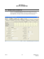
MAXPRO-Net TECHNICAL SUPPORT
REGISTRATION
License Key No:
Site name: ..........................................................................................................................................................
Company:..........................................................................................................................................................
Contact person: ..................................................
Position/title:...................................................................
Mailing Address: ...............................................................................................................................................
.............................................................................................................................................................................
.............................................................................................................................................................................
Phone:...................................................................
Facsimile:........................................................................
Technical Support Information
Honeywell provides technical support by phone to the installers and users of our various products. We
are happy to assist with installation (wiring, connections and system planning), commissioning
(identifying cabling or interconnection problems, macro programming, reconfigurations) as well as
ongoing service, fault finding and general maintenance advice.
Every licensed product receives technical support at no charge when the software has been licensed
through our technical support department. Call technical support at 972-620-6500 (1-800-796-2288 in
North America) to register your software via telephone or contact tech support at
[email protected] to register via email. The form can be mailed to the
Honeywell’s Technical Support Department located at 12880-A Valley Branch Lane, Farmers Branch, TX
75234.
Other information
If you wish to minimize the requirement of technical support, Honeywell provides technical training
courses to allow our distributors and clients to further develop their own in depth knowledge and
understanding about our products.
Please contact our company for more information at
www.honeywellvideo.com.
I agree to abide by the terms and conditions as detailed in the software license agreement.
Please Sign/date and return to Honeywell Video Systems
_____________________________________
Signature
Rev. B
_______________________________
Date
iv
HMXMU001057
31-Mar-06
TABLE OF CONTENTS
SECTION 1: GENERAL INFORMATION................................................................................................... 1
1.1
INTRODUCTION ........................................................................................................................... 1
1.2
MAXPRO-NET OVERVIEW ............................................................................................................ 1
1.3
SYSTEM STRUCTURE.................................................................................................................. 2
1.4
KEYBOARDS ................................................................................................................................ 2
1.5
MIMIC PANELS (DISCONTINUED)............................................................................................... 3
1.6
VIDEO SWITCHING SUBRACKS .................................................................................................. 3
1.7
CASCADING ................................................................................................................................. 4
1.8
COMBINING ................................................................................................................................. 4
1.9
INPUT/OUTPUT SUBRACKS ........................................................................................................ 5
1.10
MAXPRO-NET SERVER ................................................................................................................ 5
1.11
APPLICATION MODULES............................................................................................................. 5
1.12
EQUIPMENT IDENTIFICATION .................................................................................................... 5
1.13
FOLLOWING ARE THE LIST OF VIDEOBLOX COMPONENTS ................................................... 7
1.14
CONVENTIONS USED IN THIS MANUAL .................................................................................... 7
1.14.1 Points to take note of:...................................................................................................... 7
1.14.2 Manufacturer's Note......................................................................................................... 8
SECTION 2: STARTUP ............................................................................................................................. 1
2.1
MINIMAL REQUIREMENTS FOR RELIABLE PERFORMANCE .................................................... 1
2.1.1 Hardware Requirements.................................................................................................. 1
2.1.2 Software Requirements ................................................................................................... 1
2.2
INSTALLING SETMAX CONFIGURATOR ..................................................................................... 2
2.3
RUNNING THE SETMAX CONFIGURATOR ............................................................................... 13
2.4
MAXPRO-NET AND MGP-NET LICENSING ............................................................................... 14
2.5
UPGRADING MAX 1000 TO MAXPRO-NET ............................................................................... 17
2.6
MAXPRO-NET NEW SYSTEM WIZARD ...................................................................................... 19
2.6.1 Standard Tab ................................................................................................................. 20
2.6.2 VCR Management Tab .................................................................................................. 22
2.7
ADDING USERS ......................................................................................................................... 24
2.8
EDITING THE SETMAX CONFIGURATION ................................................................................ 25
2.9
SAVING DATA............................................................................................................................. 26
2.10
AUTOSAVE ................................................................................................................................. 27
2.11
CLOSING SETMAX ..................................................................................................................... 27
Rev. B
v
HMXMU001057
31-Mar-06
TABLE OF CONTENTS, CONTINUED
2.12
SETMAX ADD WIZARD............................................................................................................... 28
2.12.1 Default Tab..................................................................................................................... 29
2.12.2 Advanced Tab................................................................................................................ 29
2.13
LIVE CONFIGURATION UPDATE ............................................................................................... 31
2.14
FINDING CONFIGURATION DATA............................................................................................. 32
2.15
SERVER COLD BOOT AND WARM BOOT................................................................................. 32
2.16
SETMAX PROPERTIES............................................................................................................... 33
SECTION 3: VIDEO INPUTS..................................................................................................................... 1
3.1
DEFINING VIDEO INPUTS............................................................................................................ 1
SECTION 4: VIDEO OUTPUTS ................................................................................................................. 1
4.1
DEFINING VIDEO OUTPUTS........................................................................................................ 1
SECTION 5: SEQUENCE TABLES ........................................................................................................... 1
5.1
INTRODUCTION ........................................................................................................................... 1
5.2
DEFINING SEQUENCES .............................................................................................................. 1
SECTION 6: CCTV KEYBOARDS ............................................................................................................. 1
6.1
DEFINING CCTV KEYBOARDS .................................................................................................... 1
SECTION 7: INTERCEPT KEYBOARD KEYS........................................................................................... 1
7.1
EDITING KEYBOARD KEYS ......................................................................................................... 1
SECTION 8: KEYBOARD OPERATORS................................................................................................... 1
8.1
DEFINING KEYBOARD OPERATOR PROPERTIES ..................................................................... 1
SECTION 9: EXTERNAL ALARM INPUTS................................................................................................ 1
9.1
DEFINING EXTERNAL ALARM INPUTS ....................................................................................... 1
SECTION 10: AUXILIARY CONTROL OUTPUTS ..................................................................................... 1
10.1
DEFINING AUXILIARY CONTROL OUTPUTS............................................................................... 1
SECTION 11: SYSTEM MACRO LIBRARY............................................................................................... 1
11.1
DEFINING SYSTEM MACRO LIBRARY ........................................................................................ 1
SECTION 12: SPECIAL PARAMETERS ................................................................................................... 1
12.1
Rev. B
DEFINING SPECIAL PARAMETERS............................................................................................. 1
vi
HMXMU001057
31-Mar-06
TABLE OF CONTENTS, CONTINUED
SECTION 13: SERIAL PORTS .................................................................................................................. 1
13.1
DEFINING SERIAL PORTS ........................................................................................................... 1
SECTION 14: ERROR LOG....................................................................................................................... 1
14.1
DEFINING ERROR LOG ............................................................................................................... 1
SECTION 15: TITLE & REGISTRATION ................................................................................................... 1
15.1
TITLE & REGISTRATION .............................................................................................................. 1
SECTION 16: LOGICAL CAMERA SELECTION ...................................................................................... 1
16.1
DEFINING LOGICAL CAMERA GROUPS ..................................................................................... 1
16.2
EXAMPLE OF LOGICAL CAMERA SELECTION........................................................................... 6
16.3
HEGS5300 KEYBOARD OVERLAY............................................................................................... 7
SECTION 17: VCR MANAGEMENT.......................................................................................................... 1
17.1
VCR MANAGEMENT..................................................................................................................... 1
SECTION 18: LOGON PASSWORD ......................................................................................................... 1
18.1
LOGON PASSWORD.................................................................................................................... 1
SECTION 19: ETHERNET PORTS............................................................................................................ 1
19.1
DEFINING ETHERNET PORTS..................................................................................................... 1
SECTION 20: EXPORTING THE DATABASE FILES ................................................................................ 1
20.1
PROCEDURE TO EXPORT THE DATABASE FILES..................................................................... 1
SECTION 21: EXPORTING AND IMPORTING FILES IN EXCEL............................................................. 1
21.1
EXPORING FILE TO MICROSOFT EXCEL SPREADSHEET ........................................................ 1
21.2
IMPORTING FILE FROM MICROSOFT EXCEL SPREADSHEET ................................................. 5
Rev. B
vii
HMXMU001057
31-Mar-06
Notes:
Rev. B
viii
HMXMU001057
31-Mar-06
SECTION 1:
GENERAL INFORMATION
1.1
INTRODUCTION
This chapter contains general information that will be useful to know before using
MAXPRO-Net to configure your crosspoint matrix video switching system.
1.2
MAXPRO-Net OVERVIEW
The MAXPRO-Net crosspoint matrix video switching system is designed as an
expandable full matrix video switching system. It can be as small as eight (8) video
inputs and a single video output channel or a full matrix configuration of over 4000
cameras and 256 video output channels is possible. Larger systems can be constructed
using split matrix and networking techniques.
All video output channels can support overlaid text insertion to provide: camera
identification, channel labelling, current time/date, and other system and operator status
information.
Ninety-nine (99) individually identified keyboards can be implemented on the one
MAXPRO-Net system. Each keyboard can operate the system concurrently. If
necessary, more keyboards can be implemented using networking.
Ninety-nine (99) different operators can be defined on any one MAXPRO-Net system.
Each system operator has programmable access rights and priority codes.
Full camera control (pan, tilt, zoom, and lens functions) can be implemented for direct
control from each keyboard. Where VideoCassette Recorders (VCRs) or Digital Video
Recorders (DVRs) are utilised in a video system, the standard control functions (stop,
play, record, rewind, fast forward, pause, slow mode, and optional eject) are available
from the keyboards. Remote control interface of other video processing equipment can
also be implemented (e.g. motion detectors, freeze frame units, video multiplexers,
quads, and so on).
Remote control interface of other video processing equipment can also be implemented
(e.g. motion detectors, freeze frame units, video multiplexers, quads, and so on).
External alarm inputs and auxiliary control output circuits could also be configured into
the MAXPRO-Net system.
When the MAXPRO-Net system detects an alarm, an automatic system response can be
programmed to take place. These automatic responses are called MACRO
SEQUENCES, which allow total flexibility of system operation for any given alarm input.
More importantly, these MACRO SEQUENCES automate the responses of different
system alarms, minimizing the margin of human error during alarm conditions.
Control output circuits are used to extend the automation and control of the crosspoint
matrix video switcher. For example, they could be used to control door latches and
boom gates, which are remote from the control room.
Rev. B
1-1
HMXMU001057
31-Mar-06
1.2
MAXPRO-NET OVERVIEW, CONTINUED
Control output circuits can be directly controlled in several different ways:
•
by a given alarm input status,
•
manual operation from a keyboard,
•
or from virtually any system action that might occur.
The MAXPRO-Net crosspoint maxtrix video switching system can be structured and
configured to meet virtually any video system design specification.
1.3
SYSTEM STRUCTURE
As mentioned previously, MAXPRO-Net is structured as a matrix video switching system,
integrated with external alarm inputs and auxiliary control outputs.
1.4
KEYBOARDS
A single MAXPRO-Net system can accommodate up to ninety-nine (99) keyboards. They
can all operate the system concurrently and yet still be totally independent of each other.
Keyboards can be thought of as devices that provide the operator with a well-organized
environment to work in. All possible functions available for use in a video system can be
accessed from the keyboards, through the keys. Cameras, monitors, VCRs and pan/tilts
(PTZs) are just some of the function keys on a keyboard.
An operator to whom access is permitted can, with the correct key press, control the
allowable system devices. Keys can be reprogrammed to incorporate other functions as
well as their own designated functions, or the key could be reprogrammed to perform an
entirely different function.
The reprogramming of the keyboard keys is accomplished with the use of the 'Intercept
Keyboard Keys' table in SETMAX.
Rev. B
1-2
HMXMU001057
31-Mar-06
1.5
MIMIC PANELS (Discontinued)
Mimic panels were available as part of a MAX1000 system. These hardware panels are
no longer available with the MAXPRO-Net hardware. However, the MAXPRO-Net
configurator supports configuring these panels in systems where the software is being
upgraded.
1.6
VIDEO SWITCHING SUBRACKS
All of the available video sources (cameras etc.) are distributed across one or more
video switching subracks to construct the required video switching matrix. Depending
on the system's requirements (the number of video inputs and outputs), the video
switching subracks come in several fixed sizes to best suit individual applications.
At this point two new concepts will be introduced for use in a large switching matrix.
They are:
Rev. B
•
cascading, and
•
combining.
1-3
HMXMU001057
31-Mar-06
1.7
CASCADING
A cascading configuration may be used where the video inputs are distributed across up
to three video switching subracks. The outputs of the first subrack(s) are connected to
inputs of the subsequent subrack(s). By doing so, the subsequent video switching
subrack(s) can gain access to, in addition to their own video inputs, the other video
inputs on the previous subrack(s).
This configuration is very useful for a simple crosspoint video matrix switching system
having up to 320 video inputs. Refer to the CASCADING section of the commissioning
manual for a more comprehensive description. The commissioning manual is provided
on the CD shipped with your system.
1.8
COMBINING
Within combining configurations two different types of video switching subracks are
used:
•
pre-selection subracks, and
•
combiner subracks.
The pre-selection subracks referred to in combining are standard video switching
subracks as per those used in standalone or cascading configurations.
The combiner subracks are available in two forms: HD Series subracks configured as
combiners, or, specific combiner subracks. The choice of combiner is dependant upon
system size: HD Series subracks configured as combiners support systems with up to
1024 video inputs, whereas specific combiner subracks support systems with up to 4096
video inputs.
Video inputs are connected directly into the pre-selection subracks. The video inputs are
pre-selected by these subracks before going to the combiner subracks. The outputs
from the combiner subracks would then go to video output devices (monitors, VCR’s,
and so on).
The combining configuration is practical for video systems consisting of hundreds to
thousands of video inputs.
For more details, refer to the COMBINING section of the Commissioning Manual for a
more comprehensive description. The Commissioning Manual is located on the CD
supplied with your system.
Rev. B
1-4
HMXMU001057
31-Mar-06
1.9
INPUT/OUTPUT SUBRACKS
In order for the MAXPRO-Net system to have control over other associated equipment
(camera PTZs, VCRs, lights, boom gates, etc.), and to be able to automatically respond
to external alarm conditions, the MAXPRO-Net utilises I/O subracks.
These I/O subracks can accommodate:
1.10
•
alarm input modules,
•
control output circuit modules,
•
specialized two-wire communications modules (for camera PTZ control), and
•
peripheral control interface modules (for VCR control).
MAXPRO-NET SERVER
The MAXPRO-Net Server is programmed with the system's desired configuration and
performance specifications. It then manages all subracks and associated modules used
in the MAXPRO-Net crosspoint matrix video switcher.
The MAXPRO-Net Server simultaneously performs alarm management, remote
equipment control, and video switching (including scanning).
1.11
APPLICATION MODULES
Modules are plugged into the subracks to perform the required tasks in the crosspoint
matrix video switching system. Video switching modules, video text insertion modules,
external alarm input modules and auxiliary control output modules are all available for
use in a system. The actual number of each type of module provided with your system is
dependent upon your system's design specifications.
1.12
EQUIPMENT IDENTIFICATION
For a fully comprehensive list of components please contact Honeywell. Some of the
more commonly used components are listed below:
Following are the list of MAXPRO-Net components:
Rev. B
•
MAXPRO-Net Windows® 2003 Console Server
•
HMXAT200 Max 1000 System Controller. This can be a network node under
MAXPRO-Net system
•
HMX18 Redundant CPU Changeover Server. This can be used as an optional faulttolerant server.
•
HMX32128 Video Equipment Subrack (6RU), 16 slots for 128
inputs and 4 slots for 32 outputs
1-5
HMXMU001057
31-Mar-06
1.12
Rev. B
EQUIPMENT IDENTIFICATION, CONTINUED
•
HMX128 Subrack Controller Module for HMX32128
•
HMX832 8-Channel Video Input and Switching Module for HMX32128
•
HMX832L 8-Channel Looping Video Input and Switching Module for HMX32128
•
HMX208 8-Channel Video Output Module with Text for HMX32128
•
HMX108 8-Channel Video Output Module, without Text for HMX32128
•
HMX116 16-Channel Video Output Module, without Text for HMX32128
•
HMX4248 I/O adapter module, 24 alarm inputs, 8 relay outputs. Rear mounts onto
HMX32128
•
HMX1600 16 slot, I/O subrack (3RU)
•
HMX1676 16 input, 18 slot pre-text subrack, subrack (3RU)
•
MXCC1M Video Ribbon Cable Assembly, 3 Feet (between HMX116 video output
card and MX832L video input card) for cascading HMX32128 units).
•
MXLCM4 Cable, 8 Input Coax Ribbon Looping, 1 Foot
•
MX9018 8-Way 75-Ohm Video Termination Connector
•
CP88T75 75-Ohm Video Termination Plug
•
HMXPS9 Dual-rail subrack power supply (2RU)
•
HRD85 32 input, single channel video switching module
•
HRD89
•
HRD105B Subrack controller module
•
HMX205 Enhanced video text insertion module
•
HRD315 Two-wire PTZ communications controller module
•
HRD316 RS-485 PTZ communications controller module
•
HRD490 Infra-red Peripheral Control Interface module, VCR control (also supports
RS-232 control)
•
HRD494 Resistive-Ladder Peripheral Control Interface module
•
HEGS5300 Enhanced keyboard
•
HEGSA002 ULTRAKey control keyboard
•
HRD400 External alarm input module (8 inputs)
•
RD32C32R Combiner (6RU)
32 input, video verification module
1-6
HMXMU001057
31-Mar-06
1.13 FOLLOWING ARE THE LIST OF VIDEOBLOX COMPONENTS
•
HVBPIT44 PROTOCOL INTERFACE TRANSLATOR
•
HVBI2C16I IIC 16 INPUT Module
•
HVBI2C16O IIC 16 OUTPUT Module
•
HVBMVT Multi Channel Video Titled Card
•
HVB16M64 16 Video Input Card
•
AVB8O
•
HVB16TOX Titled Output Cards for VideoBlox
•
HVB32LKI 32 VIDEO INPUT INTERLINK INPUT
•
HVB32LKO 32 VIDEO OUTPUT INTERLINK INPUT
8 Video Output Card
Refer to the VideoBloX manual for more details on VideoBloX components.
1.14
CONVENTIONS USED IN THIS MANUAL
During the course of this manual icons and examples are used to help illustrate certain
points.
1.14.1 Points to take note of:
Points that you should be aware of will be highlighted to you in the form of a
note/caution/warning box as shown below.
NOTE:/CAUTION:/WARNING: You should pay
attention to points highlighted in paragraphs like this.
Rev. B
1-7
HMXMU001057
31-Mar-06
1.14.2 Manufacturer's Note
If you are experiencing any difficulties with your MAXPRO-Net system, or may have
some useful information to relate back to us, kindly contact your local distributor.
Our distributors are very carefully selected. They are provided with complete technical
support and training so as to ensure the high standard of service and security expected
from you.
Acknowledgements:
WINDOWS®
Registered trademark of the Microsoft Corporation
SMARTEXT™ Trademark of Honeywell, Inc.
FLASHBACK™ Trademark of Honeywell, Inc.
MAXPRO™ and MAXPRO SYSTEMS LOGO are Registered Trademarks of Honeywell,
Inc.
Rev. B
1-8
HMXMU001057
31-Mar-06
SECTION 2:
STARTUP
2.1
MINIMAL REQUIREMENTS FOR RELIABLE PERFORMANCE
2.1.1
Hardware Requirements
Component
Server Module
Description
Processor Speed: Pentium IV, 3GHz
Memory: 512 MB
Hard Disk Space: 1 GB
Monitor: 256-color VGA
Client
Processor Speed: Pentium IV, 3GHz
Memory: 512 MB
Hard Disk Space: 500 MB
Monitor: 256-color VGA
Local Area Network (LAN)
2.1.2
Ethernet or Fault Tolerant Ethernet (FTE)
Software Requirements
Software
Server Module
Description
Microsoft Windows 2003 with latest update.
Internet Explorer 5.5 or higher
Client
Microsoft Windows XP with Service Pack 2 or
Windows 2000 Professional with Service Pack 4.
Internet Explorer 5.5 or higher
Rev. B
2-1
HMXMU001057
31-Mar-06
2.2
INSTALLING SETMAX CONFIGURATOR
The SetMax Configurator must be installed on a computer running Microsoft Windows®
Server 2003 to configure the crosspoint matrix video switching system.
Perform the following steps to install SetMax for MAXPRO-Net:
CAUTION: You must be logged onto the Windows
operating system with administrative privileges.
1. Download the MAXPRO-Net software package to your computer.
2. Select and double-click the Setup.exe from the MAXPRO-Net Folder to start the
installation. The Choose Setup Language dialog appears.
3. Select a language for the installation program.
4. Click OK. The Question dialog appears.
5. Click Yes to proceed with the installation. If you click Yes, skip steps 6 to 19 and
proceed onto step 20 to continue with the installation. Click No, if you want to stop
the installation and change the installation program language.
6. If you click No in the Question dialog, the MAXPRO-Net InstallShield Wizard dialog
appears.
Rev. B
2-2
HMXMU001057
31-Mar-06
2.2
INSTALLING SETMAX CONFIGURATOR, CONTINUED
7. Click OK. The InstallShield Wizard Complete screen appears.
8. Click Finish and then change the operating system language.
Changing the operating system language
9. Choose Start Æ Settings Æ Control Panel.
10. Double-click Regional and Language Options. The Regional and Language
Options dialog appears.
Rev. B
2-3
HMXMU001057
31-Mar-06
2.2
INSTALLING SETMAX CONFIGURATOR, CONTINUED
11. In the Select an item to match its preferences, or click Customize to choose
your own formats: box, select a language for the operating system.
12. Under Location, select the location where the MAXPRO-Net is being installed.
13. Click Apply.
14. Click Advanced tab. The Advanced Settings for Regional and Language Options
appears.
Rev. B
2-4
HMXMU001057
31-Mar-06
2.2
INSTALLING SETMAX CONFIGURATOR, CONTINUED
15. In the Select a language to match the language version of the non-Unicode
programs you want to use: box, select a language for the non-Unicode programs.
16. Under Code page conversion tables, select all the items.
17. Click Apply.
18. Click OK.
19. Select and double-click the Setup.exe, in the MAXPRO-Net Folder to re-start the
installation. Refer steps 2 to 4 in this section.
Rev. B
2-5
HMXMU001057
31-Mar-06
2.2
INSTALLING SETMAX CONFIGURATOR, CONTINUED
20. If you click Yes in the Question dialog, the Welcome screen appears.
21. Click Next. The Select Features screen appears.
22. Select the features to install.
Note: If MAXPRO-Net Server is selected, the setup installs Microsoft SQL Server Desktop
Engine on your computer.
Rev. B
2-6
HMXMU001057
31-Mar-06
2.2
INSTALLING SETMAX CONFIGURATOR, CONTINUED
23. Click Browse. The Choose Folder dialog appears.
24. Select a folder where the features are to be installed.
25. Click OK to close the Choose Folder dialog.
26. Click Next on the Select Features screen. If you have selected MAXPRO-Net Server
on the Select Features screen, the Choose Destination Location screen appears.
27. Click Browse. The Choose Folder dialog appears.
28. Select a folder where Microsoft SQL Desktop Engine is to be installed.
29. Click OK to close the Choose Folder dialog.
30. Click Next on the Choose Destination Location screen. The Database Server Login
screen appears.
Rev. B
2-7
HMXMU001057
31-Mar-06
2.2
INSTALLING SETMAX CONFIGURATOR, CONTINUED
31. In the Login ID box, type the SQL User Login ID.
32. In the Password box, type the SQL User Password.
33. Click Next. The User Information screen appears.
34. In the Select Language box, select the language to be used for MAXPRO-Net.
Rev. B
2-8
HMXMU001057
31-Mar-06
2.2
INSTALLING SETMAX CONFIGURATOR, CONTINUED
Note: Refer to MAXPRO-Net Translation Editor User Manual.pdf (Revision 1.0), having
the part number 900.0675, if you want to add support for other languages in
MAXPRO-Net.
35. Click Next. The Start Copying Files screen appears.
36. Click Next. The Microsoft SQL Server Desktop Engine installation dialog appears.
Note: The computer restarts after Microsoft SQL Sever Desktop Engine is installed.
The SQL Server Network Utility screen appears after the Microsoft SQL Server Desktop
Engine installation is completed.
Rev. B
2-9
HMXMU001057
31-Mar-06
2.2
INSTALLING SETMAX CONFIGURATOR, CONTINUED
37. In the Disabled protocols box:
a. Select Named Pipes and click Enable.
b. Select TCP/IP and click Enable.
38. Click OK to close the SQL Server Network Utility screen. The SQL Server Network
Utility dialog appears.
39. Click OK. The computer restarts and the Choose Setup Language dialog appears.
Rev. B
2-10
HMXMU001057
31-Mar-06
2.2
INSTALLING SETMAX CONFIGURATOR, CONTINUED
40. Select a language for the installation program.
41. Click OK. The Question dialog appears.
42. Click Yes. The Start Copying Files screen appears.
The Install Shield Wizard Complete screen appears after the installation is completed.
Rev. B
2-11
HMXMU001057
31-Mar-06
2.2
INSTALLING SETMAX CONFIGURATOR, CONTINUED
43. Click Finish to complete the installation.
Rev. B
2-12
HMXMU001057
31-Mar-06
2.3
RUNNING THE SETMAX CONFIGURATOR
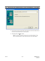
1. Choose Start -> Programs -> Honeywell Video Systems -> SetMax for Windows
-> Setmax for Maxnet. The Setmax Configurator dialog appears:
2. In the IP Address box, select or type the Server IP Address.
3. In the User Name box, type the user name.
4. In the Password box, type the password.
5. In the Language box, select the language you want to use.
6. Click OK.
Rev. B
2-13
HMXMU001057
31-Mar-06
2.4
MAXPRO-NET AND MGP-NET LICENSING
First time when you log on to SetMax, the 30 days of trial version message appears.
When you obtain the registered product license, you can use the license key and
change the status using the License option from the Help menu.
1. When you logon to SetMax, the following main window appears:
2. Read the license information on the dialog and click OK.
3. When you want to update the license status, select Help -> License menu from the
main window. The following dialog appears:
Rev. B
2-14
HMXMU001057
31-Mar-06
2.4
MAXPRO-NET AND MGP-NET LICENSING, CONTINUED
4. Copy the site code from the text box and send it to the Customer Care at Honeywell.
Mention the required number of licenses for MGP-NET when sending the site code.
Use the following license form to fill in this information:
5. After you receive the Site Key from the vendor, specify the same in the Site Key field.
Rev. B
2-15
HMXMU001057
31-Mar-06
2.4
MAXPRO-NET AND MGP-NET LICENSING, CONTINUED
6. Click the Save Site Key button to update the license.
7. Click Close.
8. Now the license gets updated and the licensed status is displayed accordingly.
9. Click Connect to retrieve the configurations.
Rev. B
2-16
HMXMU001057
31-Mar-06
2.5
UPGRADING MAX 1000 TO MAXPRO-NET
If you are upgrading your system from max files Version 4.16 or later to MAXPRO-Net,
you can import the .max files already configured.
1. Select Tools -> Import Max Files from the menu bar as shown in the following
illustration.
2. Locate and select the existing title.max file. The following window displays an
example location.
Rev. B
2-17
HMXMU001057
31-Mar-06
2.5
UPGRADING MAX 1000 TO MAXPRO-NET, CONTINUED
3. Click Open.
4. The files are imported and the system is configured as it was in your previous
version of SetMax. After importing, you need to cold boot the server to reflect the
configuration of imported files.
Rev. B
2-18
HMXMU001057
31-Mar-06
2.6
MAXPRO-Net NEW SYSTEM WIZARD
To configure a new system using the New System Wizard, perform the following steps:
1. Select Tools -> New System Wizard from the menu bar, as shown in the following
illustration.
2. The following New System Wizard window appears.
Rev. B
2-19
HMXMU001057
31-Mar-06
2.6.1
Standard Tab
Inputs
Cameras
Enter the number of cameras (fixed and PTZ) in the system.
Press the Tab key on the keyboard to move to the next field or left
mouse click on another field. Pressing Shift+Tab moves the
cursor to the previous field.
VCRs
Enter the number of videocassette recorders connected to video
inputs in the system. Press the Tab key on the keyboard to move
to the next field or left mouse click on another field. Pressing
Shift+Tab moves the cursor to the previous field.
Enter the number of standard devices (other devices, freeze
frames, etc.). Press the Tab key on the keyboard to move to the
next field or left mouse click on another field. Pressing Shift+Tab
moves the cursor to the previous field.
Enter the number of smart devices (such as multiplexers) in the
system. Press the Tab key on the keyboard to move to the next
field or left mouse click on another field. Pressing Shift+Tab
moves the cursor to the previous field.
Assigns the system menu output to a video input. If an operator
is required to log on the system to access the system
configuration, the Menu check box must be selected in order for
the operator to view the system menu.
Standard Device
Smart Device
Menu
Outputs
Monitors
VCRs
Standard Device
Smart Device
Rev. B
The total number of video inputs allowed in a MAXPRO-Net
system is 9999.
The total number of video outputs allowed in a MAXPRO-Net
system is 999.
Enter the number of monitors in the system. Press the Tab key on
the keyboard to move to the next field or left mouse click on
another field. Pressing Shift+Tab moves the cursor to the
previous field.
Enter the number of videocassette recorders connected to video
outputs in the system. Press the Tab key on the keyboard to
move to the next field or left mouse click on another field.
Pressing Shift+Tab moves the cursor to the previous field.
Enter the number of standard devices (other devices, freeze
frames, etc.). Press the Tab key on the keyboard to move to the
next field or left mouse click on another field. Pressing Shift+Tab
moves the cursor to the previous field.
Enter the number of smart devices (such as multiplexers) in the
system. Press the Tab key on the keyboard to move to the next
field or left mouse click on another field. Pressing Shift+Tab
moves the cursor to the previous field.
2-20
HMXMU001057
31-Mar-06
Options
Use Cascading If
Required
For Combining
configuration use
HD hardware if
possible
If the system is using a cascading configuration, select the field
by left mouse clicking on the check box. Left mouse clicking on
this field toggles select and deselect. If the check box contains a
check mark, the field is selected.
If the system is using a Combining configuration, select the field
by left mouse clicking on the check box. Left mouse clicking on
this field toggles select and deselect. If the check box contains a
check mark, the field is selected.
Others
Keyboards
Operators
Communication
Ports
Rev. B
Enter the number of keyboards in the system. The maximum
number of keyboards per system is 99. Press the Tab key on the
keyboard to move to the next field or left mouse click on another
field. Pressing Shift+Tab moves the cursor to the previous field.
Enter the number of operators that will be using the system. The
maximum number of operators per system is 99. Press the Tab
key on the keyboard to move to the next field or left mouse click
on another field. Pressing Shift+Tab moves the cursor to the
previous field.
Enter the number of communication ports in the system. The
maximum number of communication ports in a single system is
20. Press the Tab key on the keyboard to move to the next field or
left mouse click on another field. Pressing Shift+Tab moves the
cursor to the previous field.
2-21
HMXMU001057
31-Mar-06
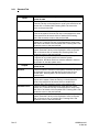
2.6.2
VCR Management Tab
To configure the VCRs in the system left mouse click on the VCR Management tab. The
following dialog box opens.
VCRs
Dedicated VCRs
Dedicated VCRs
begin in next
Subrack
Standby VCRs
VCRs Per Bank
Rev. B
Enter the number of dedicated VCRs in the system. Press the Tab
key on the keyboard to move to the next field or left mouse click
on another field. Pressing Shift+Tab moves the cursor to the
previous field.
Left mouse click on this box (check mark in the box) if you want
the dedicated VCRs to begin in the next subrack.
Enter the number of standby VCRs. Press the Tab key on the
keyboard to move to the next field or left mouse click on another
field. Pressing Shift+Tab moves the cursor to the previous field.
Enter the number of VCRs per bank. Press the Tab key on the
keyboard to move to the next field or left mouse click on another
field. Pressing Shift+Tab moves the cursor to the previous field.
2-22
HMXMU001057
31-Mar-06
Pretext Parameters
Text Position
Text Attributes
VCRs per PreText
Subrack
Enter the X and Y coordinates on the video display to position
text. Press the Tab key on the keyboard to move to the next field
or left mouse click on another field. Pressing Shift+Tab moves
the cursor to the previous field.
Left mouse click on the –S-E button to open the text attributes
dialog box.
Select either the Enhanced text card or Hidden text card as
applies to your system. The Shadow and Double Height features
both can be selected for either type text card. If you left mouse
click on the Select All button, the Hidden text card, Shadow, and
Double Height are selected.
When the text attributes are set, left mouse click on the OK button.
Left mouse click on the Cancel button to exit the dialog box
without making changes.
Enter the number of VCRs per PreText Subrack.
When your video system is configured, press the OK button. The Setmax program
creates the files required to setup your system. Each file Setmax creates is represented
by a tab in the Setmax window. The file name of the master file that contains the
individual files (tabs) is title.max.
Rev. B
2-23
HMXMU001057
31-Mar-06
2.7
ADDING USERS
To add new users of SetMax, perform the following steps:
1. Select Tools -> Add Users from the menu bar. The following dialog appears:
2. Click Add.
3. Type the user name and the password in the respective fields and click Save.
4. Select the user under Current Users and click Delete to delete the existing user.
However, you cannot delete the Admin user, which is a default one.
5. Click Close to close the Add Users dialog.
Rev. B
2-24
HMXMU001057
31-Mar-06
2.8
EDITING THE SETMAX CONFIGURATION
To select a file, left click on its tab or press Alt and the underlined letter on the tab. For
example, press Alt+I at the same time to select the Video Inputs file.
To edit a field within a configuration page:
a) Click on the field using the left mouse button (left mouse click) or use the up, down,
left, and right arrows on the keyboard to move to the desired field and press Enter.
When the field is active, the background turns from yellow to white and the cursor
blinks within the field. If there is a pull-down menu for the field, a down arrow
appears on the right side of the cell.
b) Enter the desired information in the field and press Enter, or select an option from
the pull-down menu and press Enter. The cursor moves to the field below.
c) To access a pull-down menu, left click on the down arrow in the field.
d) To select an option in a pull-down menu, left mouse click on the option or press the
up and down arrows keys on the keyboard until the desired option is highlighted.
Press Enter on the keyboard to enter the selection in the cell.
e) To view more columns within a file, left mouse click on the arrows in the horizontal
scroll bar on the bottom right side of the window. To view more rows within a file,
left mouse click on the arrows in the vertical scroll bar on the right side of the
window.
f)
To exit the edit mode without changing the field, press Esc on the keyboard.
Refer to the following chapters for assistance in editing each file for your system.
Rev. B
2-25
HMXMU001057
31-Mar-06
2.9
SAVING DATA
Periodically, save your editing to safeguard against loss of information.
To save information entered in the current file,
Left click on File, then left click on Save or left click on the single Disk Icon.
Single Disk Icon
To save information entered in all files,
Left click on File then left click on Save All or left click on the Multiple Disk Icon.
Multiple Disk
Icon
For the operations that take few seconds / considerable time to get the response, the
notification will be displayed with the message to allow users understand that a specific
task is in progress.
Rev. B
2-26
HMXMU001057
31-Mar-06
2.10
AUTOSAVE
You can have SetMax save the data automatically at designated intervals. Perform the
following procedure to have SetMax automatically save your changes.
1. Left mouse click on Tools on the main menu.
2. Left mouse click on Options. The following dialog box opens.
3. Left mouse click on the AutoSave every check box to select AutoSave.
4. In the minutes field, enter how often (1-60 minutes) you want SetMax to save your
files. For example, enter 10 in this field to have SetMax save your files every 10
minutes.
5. If you want SetMax to prompt you before saving, left mouse click on the Prompt
before saving check box. If this box is left unchecked, SetMax will save at the
designated intervals without advising you.
Once the required configuration is completed, the MAXPRO-Net server can be restarted
to make the system operational. If you are starting the system for the first time, the time
and date will need to be set to your local time. Refer to the operator’s manual for the
procedures to set the date and time.
2.11
CLOSING SETMAX
After saving all changes, close the file.
1. Left click on File.
2. Left click on Exit. If you haven’t saved your files, you will be prompted to save. Left
click on Yes to save editing, No to exit without saving, or Cancel to end the Exit
command.
Rev. B
2-27
HMXMU001057
31-Mar-06
2.12
SETMAX ADD WIZARD
Your video system can be expanded (if it has not reached the maximum devices) using
the Add Wizard. The devices that can be added using the Wizard are Video Inputs,
Video Outputs, Auxiliary Control Outputs, External Alarm Inputs, CCTV Keyboards, and
Intercept Keys.
1. Select the tab of the device type where you want to add devices. Left mouse click
on Tools on the MAXPRO-Net menu bar then left mouse click on Add Wizard. The
following dialog box opens.
2. Select a device within the file to use for a template of the additional device(s).
Rev. B
2-28
HMXMU001057
31-Mar-06
2.12.1 Default Tab
Default Tab
Template Device
Number of Devices to
Add
Add from line
The template device defaults to the device type of the device
selected. For example, if camera 1 on the video inputs tab is
selected, the additional devices will be setup the same as camera
1. The user can change any necessary parameters after inserting
the devices.
Enter the number of devices you want to add to your current
system and press Enter on the keyboard.
The add wizard starts the line numbering with the next available
device. For example, if your system contains 128 cameras, the
add wizard starts the line numbering at 129.
2.12.2 Advanced Tab
Left mouse click on the Advanced Tab.
Rev. B
2-29
HMXMU001057
31-Mar-06
Advanced Tab
Format item
First numeric value
The format item is used to define the field of the template to be
used for formatting the new device. The format item is selectable
depending on the device being added. For example, a video
input format item can only be device description. A video output
format item is selectable between device description or default
video input. Select the desirable format item for the device being
added.
Check this box to increase the numeric value of the new device by
one more than the selected template device. For example, if the
Device Description is Camera 1, when you check this box, the
Device Description for the first added device is Camera 2. If you
do not check this box, the camera description would remain the
same as the selected template. In the above example, the
camera description would remain at Camera 1 for the new device.
When the fields are completed for the added devices, left mouse click on the OK button.
To exit the wizard without adding devices, left mouse click on the Cancel button.
Configure the added devices as required for each device. Refer to the following
chapters for assistance. When new devices are configured, save all data. The changed
configuration can be updated to the MAXPRO-Net Server either through LIVE update or
by COLD BOOT as explained in the following topics.
Rev. B
2-30
HMXMU001057
31-Mar-06
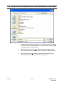
2.13
LIVE CONFIGURATION UPDATE
Configurations can be changed in SetMax and updated live to the server by selecting
the Live Update button
or selecting Update option from the Update menu.
If there is a column label with a blue color background (in column heading) under any of
the SetMax tabs, it indicates that those configuration changes will not be live updated to
the MAXPRO-Net server. However, these configurations changes take effect only on a
cold boot of the server. The following illustration shows some of the columns with blue
color background, which do not get live updated to the server:
Rev. B
2-31
HMXMU001057
31-Mar-06
2.14
FINDING CONFIGURATION DATA
Select the Edit->Find option or press F3 to find the data from the current tab. The labels of each
column is listed under Category as shown in the following illustration:
2.15
SERVER COLD BOOT AND WARM BOOT
You can perform cold boot or warm boot of the MAXPRO-Net server from SETMAX.
Server ColdBoot [
]: Use this option to restart the MAXPRO-Net server.
Server WarmBoot [
]: Warm Boot does not require any restart of the server. Selection of this
option reinitializes all the devices connected to Max system without any restart or shutdown of
MAXPRO-Net server.
Rev. B
2-32
HMXMU001057
31-Mar-06
2.16
SETMAX PROPERTIES
The properties dialog provides details about number of devices configured in SetMax as shown
in the following illustration:
Rev. B
2-33
HMXMU001057
31-Mar-06
Notes:
Rev. B
2-34
HMXMU001057
31-Mar-06
SECTION 3:
VIDEO INPUTS
3.1
DEFINING VIDEO INPUTS
Selection of the Video Inputs tab opens the file for editing the properties for each video
input. The details for each field in the file are described below.
Rev. B
3-1
HMXMU001057
31-Mar-06
Video Inputs
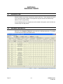
The total number of video inputs allowed in a MAXPRO-Net system is 9999.
Ref
Device Type
The video input reference number is purely a reference number
used to distinguish one video input device from another
(regardless of the video input device type – cameras, VCRs, etc.).
The video input reference number field is NOT a changeable field.
Each video input device must be given a device type so
MAXPRO-Net knows what selection and control parameters apply
to the device. You may either select the device type from the list
box as shown below or type in the required device (most of the
device types are selectable by merely typing in the first character,
e.g. c or C will automatically select Camera).
The currently supported video input device types are as follows:
•
Camera - fixed and PTZ
•
VCR (video cassette recorder) - dedicated or Dub VCR
•
Smart Device - devices such as multiplexers
•
Standard Device - other devices, freeze frames, etc.
•
Trunk - trunk video input (from a networked system)
•
Menu - MAXPRO-Net system menu (using MaxMon)
•
Black Source - black source for monitor blanking, etc.
•
Standby VCR - Standby VCR as used in VCR
Management
•
Logging VCR - Monitor logging VCR as used in VCR
Management
When the desired device type is displayed in the field, press Enter
on the keyboard.
Rev. B
3-2
HMXMU001057
31-Mar-06
Video Inputs, Continued
Device Number
Source Group
Device Description
Primary Subrack ID
Rev. B
Each video input device must have a unique device number
allocated to it. This device number is unique with respect to other
video inputs of the same type and does not relate to the video
input reference number (REF) or its physical connection to the
system.
Definitions in the video input DEVICE TYPE and DEVICE
NUMBER fields allow exact selection of the video input device
from a keyboard. The valid range for device numbers is 1 – 9999.
Enter the desired device number and press Enter on the
keyboard.
A source group is a group of video input devices (cameras,
VCR’s etc.) that are linked together as specific access groups.
This allows the system to control which video output channels
have access to which video inputs. Due to hardware restrictions
some monitors may only be able to access certain video inputs.
Source groups are also used to partition video input selections
for specific operators.
A source group number is allocated for every video input. The
default source group is 0, the range of allowable source groups
is 0 – 99.
Enter the desired source group number and press Enter on the
keyboard.
This is an 18-character description used to identify the selected
video input device. It is displayed on a monitor (or other video
output channel with text insertion) whenever the video input
device is selected. It is also used by video fail alarms to identify
the failed video input device.
Enter the desired description (up to 18-characters) in the field
and press Enter on the keyboard.
This is the address of the subrack to which the video input is
physically connected. Valid primary subrack addresses range
from 1 – 99. A value of '0' indicates that no video switching will
occur when the device is selected (often used where a device
needs to be selected by a keyboard for control purposes, but no
video switching is required).
Enter the address of the subrack and press Enter on the
keyboard.
For Videoblox subrack, this ID represents the
‘V’+communication port number to which the VideoBlox analog
video input cards are connected. Valid primary subrack
addresses range: ‘V’+maximum communication ports. Suffix ‘A’
with primary subrack ID (e.g., V1A) indicates that the audio is
enabled for that particular video input.
3-3
HMXMU001057
31-Mar-06
Input Number
Video Inputs, Continued
This is the physical connection point on the primary subrack. The
valid range for the video input number is 1 - 128. Certain subrack
types have fewer than 128 video inputs.
•
HMX1132 - maximum video input number is
32.
•
HMX32128 HD-Series subrack .. up to the
maximum 128.
Enter the video input number on the subrack and press Enter on
the keyboard.
For VideoBlox subrack, this is the physical input location of the
video input channel. The valid range for the VideoBlox is 1 4096.
For input numbers 1 to 16 – the input card address is 0.
For input numbers 17 to 32 – the input card address is 1.
Rev. B
3-4
HMXMU001057
31-Mar-06
Video Inputs, Continued
Subrack
Settings
Selecting the SUBRACK SETTINGS field opens three additional fields that are used in
cascading and combining configurations.
Bypass
Subrack ID
Combiner
Subrack ID
Subrack
Settings,
Cont.
Rev. B
Combiner
Input Number
This field is used in cascading configurations only and contains the
address of the subrack, which is to be bypassed when selecting the
current video input device. For more comprehensive details please
refer to the CASCADING section of the Commissioning Manual.
For VideoBlox subrack, the Bypass subrack ID value should be 1-16,
depending on the input device number. For the first 1-255 physical
inputs, the bypass ID is 1, and for the next 1-255 inputs, the bypass ID
is 2, and so on.
This field may be used in both cascading and combining
configurations. In a cascading configuration consisting of three
subracks, the COMBINER SUBRACK ID contains the address of the
second subrack that is to be bypassed when selecting the current
video input device. For more comprehensive details please refer to
the CASCADING section of the Commissioning Manual. The following
figure shows typical entries for a cascaded system:
In combining configurations this field contains the address of the
combiner subrack. For more comprehensive details please refer to
the COMBINING section of the Commissioning Manual.
The valid address values are 0 (signifying no cascading or combining
are used) through to 99.
This field defines the combiner inputs to which the preselector
subrack for the current video input is connected. Up to 32 preselector
subracks may be configured, the combiner inputs for these are
labeled A – Z and AA – AF. For more comprehensive details please
refer to the COMBINING section of the Commissioning Manual.
3-5
HMXMU001057
31-Mar-06
Video Inputs, Continued
Net Source
Alternate
Camera
Number
Alternate
Camera
View
Source
Control
When the current video input is actually connected to another MAXPRO-Net system
within a network configuration, the NET SOURCE field is used to specify the exact
location and reference for the video input device.
e.g. #03:C1234 the actual camera resides on network node 3 and is defined there as
camera 1234.
LINK
- signifies that status changes and actions performed on the current
video input device will be broadcast on the network.
The NET SOURCE field additionally allows for the definition of pseudo cameras, i.e. a
combined camera and preset view position, which is allocated as a unique camera
number.
e.g. C56:V99
For more comprehensive details, please refer to the NETWORKING section of the
Commissioning Manual.
This field defines the alternate camera to be selected when the 'ALT' key is pressed on a
keyboard. The range of valid camera numbers is 1 – 9999. The alternate camera also
has to be defined elsewhere in the video input table. Zero (0) is the default value and
indicates no alternate camera is defined.
The alternate camera can also be a PTZ camera with view recall capability. In this case
an actual VIEW number can be specified, pressing the 'ALT' key will now not only display
the alternate camera, but will also automatically move it to the designated VIEW preset
position. The valid camera views range is 1 – 99, 0 is the default value which indicates
no camera view is to be selected.
Note: As view number '0' is used to indicate that NO VIEW is specified, view '0' cannot
be recalled by this field. The view must also be programmed in the camera for this
feature to be functional.
Selecting the SOURCE CONTROL field displays four additional fields that are used to
define the control properties for the current video input device.
Control ID
Rev. B
This field contains the address of the subrack where the controller for the
current video input device (e.g. RD316, RD490 etc.) resides. The valid
range for CONTROL ID is 1 – 799, a value of 0 indicates no control
capability for the device.
For VideoBlox subrack, this ID represents the communication port
number to which the VideoBlox video input camera control lines are
connected. Valid range: ‘V’+maximum communication ports.
3-6
HMXMU001057
31-Mar-06
Source
Control
Cont.
Control
Slot
Control
Offset
Available
Control
Rev. B
Video Inputs, Continued
This field defines the slot number within the control subrack where the
controller for the current video input device (e.g. HRD316, HRD490 etc.)
resides. Valid slot numbers are 1 – 32 for I/O and combination video/I/O
subracks and 1 – 8 for HD Series subracks.
Within subracks such as HMX1132 and HMX1600, the CONTROL SLOT
is the physical slot where the controller card resides. Whereas within HD
Series subracks (HMX32128) device control and I/O functions are
mapped to pseudo slots as all of these functions exist on the subrack
controller card (HMX128) located in slot 0.
For VideoBlox subrack, the control slot number should be greater than
zero.
Valid range: 1 to 4.
For controlling a PTZ camera, enter the ID number of the PTZ site
receiver connected to that camera. The valid range for site ID's is 1 – 16.
A 0 indicates that a hardwired relay output module is being used in the
subrack slot for controlling that camera.
When controlling other equipment types (e.g. VCRs) the CONTROL
OFFSET field can be used to define the output number on the controller
card in the specified subrack slot. The valid range of output numbers is 1
– 8. A 0 indicates that a hardwired relay output module is being used in
the subrack slot for controlling the device
For VideoBlox subrack, this represents the camera number of the video
input channel. Valid range: 1 to 255.
Selecting this field brings up a dialog box which allows configuration of
which control functions are available for the current video input device.
The available control functions vary between the different types of video
input device as shown in the following figures.
To select (or deselect) a control, left mouse click on the check box
beside the control function. If the box contains a check mark, the
function is selected. To select or deselect all the control functions, left
mouse click on the Select All or Deselect All button.
When the desired control functions are selected, left mouse click on the
OK button. To exit the dialog box with making changes, left mouse click
on the Cancel button.
Camera:
3-7
HMXMU001057
31-Mar-06
Video Inputs, Continued
Source
Control
Cont.
Available
Control,
Cont.
VCR, Logging VCR, Standby VCR:
Standard Device, Smart Device:
Control
Locked
Source
Disable
Pretext
Rev. B
The source controls of a PTZ camera site (or VCR etc.) can be locked to prevent user
control of the device. The default lock/unlock status is specified here.
Note: This locked status can be unlocked by the system operator (if they have the
correct System Access Level) from the MAXPRO-Net Menu System (using MaxMon).
When a video input needs to be temporarily removed from the video input selection
table, the SOURCE DISABLE field would be set to YES. While set, the video input
device CANNOT be selected by any operator. Under normal operation this field is 'NO'.
To disable a particular video input device, a 'YES' is specified in this field. Enter Y or N in
this field and press Enter on the keyboard.
The SOURCE DISABLE state can be changed (using macro programming) while the
system is in operation e.g. [C123=T] or [C123=F] or through MaxMon.
Selecting this field allows access to the parameters used to define pretext as used in
VCR management applications (refer to the VCR Management section of the user’s
guide for a comprehensive description).
3-8
HMXMU001057
31-Mar-06
Pretext Subrack ID
Video Inputs, Continued
This field defines the address of the subrack, which contains
the text insertion card (RD200, RD205, MX205, RD220) for
pretext. The valid range of subrack addresses is 1 – 799, a
value of 0 indicates pretext is not used.
For VideoBlox subrack, this ID represents the
‘V’+communication port number to which VideoBlox MVT
(Multi Channel Video Titler) is connected. Valid range:
‘V’+maximum communication ports.
Pretext Slot Number
Dynamic
Equalisation
Source
Macro Flags
This field defines the physical slot number within the pretext
subrack where the text insertion card resides. The valid range
of slot numbers is 1 – 32.
For VideoBlox subrack, this number represents the physical
input slot for the VideoBlox analog input channel in MVT. Valid
range: 1 to 4096.
For pretext slot numbers 1 to 16 – MVT address is 1.
For pretext slot numbers 17 to 32 – MVT address is 2.
X, Y
These two fields define the horizontal (X) and vertical (Y)
location of the pretext, valid positions are 1 –13. These X and Y
coordinates are also the dynamic text coordinates where this
feature is enabled for video output channels.
Where text insertion modules which support dynamic cable equalization are utilized this
field represents the cable length between the video input device and the switcher. Valid
DYNAMIC EQUALISATION values are 1 – 8 representing units of one hundred meters of
RG-59/BU coaxial cable.
For different coaxial cable types the signal losses may be considerably different to the
losses of RG-59/BU (e.g. RG-8 and RG-11 have considerably lower losses). Where
different coaxial cable types are used the DYNAMIC EQUALISATION value should be
varied to optimize image quality.
Note: If a dynamic equalization value is stated for ONE camera, then ALL cameras must
have a dynamic equalization value other than (0). Dynamic equalization serves to
improve image quality by providing compensation for cable related transmission losses,
dynamic equalization does not guarantee a maximally flat response with any given cable
distance or type.
This field allows for definition of the default cold boot state of the macro flags for the
current video input device.
Left mouse click on any of the fields to toggle their state, a ticked field indicates the
macro flag is set TRUE. Left mouse click on the ‘All’ field to toggle the state of all macro
flags.
When the Source Macro Flags are set as desired, left mouse click on the OK button. To
exit the dialog box without making changes, left mouse click on the Cancel button.
Rev. B
3-9
HMXMU001057
31-Mar-06
Video Fail
Slot
Start Macro
Finish
Macro
Rev. B
Video Inputs, Continued
To enable automatic video fail detection, enter the slot number where the video fail
detector module is located. This would be in the primary video input pre-selection
subrack specified earlier in the PRIMARY SUBRACK ID field. The valid subrack slot
numbers are 1 – 32. HD Series subracks (HMX32128) perform video fail detection on the
HMX128 subrack controller card, this is mapped to pseudo slots as follows:
Video Inputs
Video Fail Slot
1 – 32
11
33 – 64
12
65 – 96
13
97 – 128
14
Enter a 0 when video fail detection is not required.
NOTE: This is valid for cameras (and trunk inputs) only. For video inputs of other device
types this field will NOT accept an entry.
For VideoBlox Subrack, the Video fail slot should be 1.
The START MACRO is executed whenever a video alarm condition is detected for the
corresponding video input device.
The video alarm types are:
•
Video fail detection (for cameras)
•
PTZ site fail (for cameras)
•
PTZ site tamper (for cameras)
• Video source related alarm (for VCRs)
Please refer to the MACRO GUIDE in the Operator’s Manual for comprehensive details of
macro functionality.
Type the desired macro number and press Enter on the keyboard.
The FINISH MACRO is executed whenever the video alarm condition is cleared (i.e.
video signal, PTZ site fail, is restored to normal).
Please refer to the MACRO GUIDE for comprehensive details of macro functionality.
Type the desired macro number and press Enter on the keyboard.
3-10
HMXMU001057
31-Mar-06
SECTION 4:
VIDEO OUTPUTS
4.1
DEFINING VIDEO OUTPUTS
Selection of the Video Outputs tab opens the file for editing the properties for each
video output. The details for each field in the worksheet are described below.
Video Outputs
The total number of video outputs allowed in a MAXPRO-Net system is 999.
Ref
Rev. B
The video output reference number is purely a reference number used to
distinguish one video output device from another (regardless of the
video output device type – monitors, VCRs, etc.). The video output
reference number field is NOT a changeable field.
4-1
HMXMU001057
31-Mar-06
Video Outputs
The total number of video outputs allowed in a MAXPRO-Net system is 999.
Slot
The slot number is used to identify the actual SLOT location of each
video output channel. In a standard configuration, the default channel
number allocations do not require any change. When one MAXPRO-Net
system is controlling multiple partitioned video matrixes, it is necessary
to redefine slot numbers for each video matrix used.
Within HD Series subracks (MX32128) the video output channels are
mapped to slots 1 – 32 (corresponding to physical outputs 1 – 32).
Note: BE CAREFUL when redefining slot numbers. Source
grouping must be used to prevent camera selections across matrix
hardware boundaries.
Device Type
To change the slot number, type the desired number and press Enter on
the keyboard.
Each video output device has a device type to indicate to MAXPRO-Net
what selection and control parameters apply to the device. You may
either select the required device type from the list box as shown below or
by typing in the required type (most of the device types are selectable by
merely typing in the first character e.g. m or M will automatically select
Monitor).
The currently supported video output device types are as follows:
•
Monitor - standard video output device
•
VCR - video cassette recorder
•
Smart Device - devices such as multiplexers
•
Standard Device - other devices, freeze frames, etc.
•
Trunk - trunk video input (from a networked system)
•
Standby VCR - Standby VCR as used in VCR Management
When the desired device type is displayed, press Enter on the
keyboard.
Device Number
Rev. B
Each video output device must have a unique device number allocated
to it. This device number is unique with respect to other video outputs of
the same type and does not relate to the video output reference number
(REF) or its physical connection to the system.
Definitions in the video output DEVICE TYPE and DEVICE NUMBER
fields allow exact selection of the video output device from a keyboard.
The valid range for device numbers is 1 – 999.
Enter the device number and press Enter on the keyboard.
4-2
HMXMU001057
31-Mar-06
Video Outputs
The total number of video outputs allowed in a MAXPRO-Net system is 999.
Description Text
Text Inserter
Subrack
Text Inserter
Slot
Text Display
Status
X, Y
Rev. B
This is an 18-character description used to identify the selected video
output device. It is displayed on the monitor (or other video output
channel with text insertion).
Type the desired description (up to 18 characters) and press Enter on
the Keyboard.
This field defines the address of the subrack, which contains the text
insertion card (MX208, RD200, RD205, MX205, RD220) for this video
output device. The valid range of subrack addresses is 1 – 799; a value
of 0 indicates text is not used.
Enter the desired value and press Enter on the keyboard.
For VideoBlox subrack, this address represents the ‘V’+communication
port number to which the VideoBlox analog video output cards are
connected. Valid range: ‘V’+maximum communication ports.
This field defines the slot number within the subrack where the text
insertion card resides. The valid range of slot numbers is 1 – 32. HD
Series hardware supports the MX208 8 channel video output/text
insertion card, the TEXT INSERTER SLOT entries correspond with the
physical video output channel of the subrack.
For VideoBlox subrack, this number represents the physical input
location of the video output channel. Valid range: 1 to 255 for VideoBlox.
Selecting the TEXT DISPLAY STATUS field provides for definition of the
text attributes for this video output device.
Left mouse click on the check box beside the attribute field to toggle its
status. If a check mark is present, the attribute is selected.
To select or deselect all attributes, left mouse click on the Select All or
Deselect All button. When the desired attributes are selected, left mouse
click on the OK button. To exit the dialog box without making changes
to the attributes, left mouse click on the Cancel button.
These two fields define the horizontal (X) and vertical (Y) location of the
onscreen text, valid positions are 1 –13. A value of 0 in both of these
fields enables the dynamic text positioning function, whereby text will be
positioned according to the X and Y coordinates specified in the
PRETEXT fields of the currently selected video input device.
Enter the desired value and press Enter on the keyboard.
4-3
HMXMU001057
31-Mar-06
Video Outputs
The total number of video outputs allowed in a MAXPRO-Net system is 999.
Enable Text Line
Time Out
Net Device
Default Video
Input
Selecting the ENABLE TEXT LINE field allows for configuration of the text
lines to be displayed on the current video output device.
Left mouse click on the check boxes beside the selections to toggle their
status. A check mark in the box indicates it is selected. Left mouse click
on OK when selections are as desired. To Deselect All, left mouse click
on Deselect All. To exit the Enable Text Line dialog box without making
any changes, left mouse click on Cancel.
When a video monitor (or other video output device) is not being used it
is sometimes desirable to remove the displayed picture from the monitor,
leaving a blank screen. The system will try to select the BLANK video
input defined in the video input table so a Black Video Source could be
displayed. If no BLANK input is defined, then the system will only remove
the text insertion window, leaving the actual picture on display.
The display time-out period can be set from 1 – 999 seconds. Enter a
zero (0) in this field if the display time out function is not required.
When the current video output device is actually connected to another
MAXPRO-Net system within a network configuration, the NET DEVICE
field is used to specify the exact location and reference for the video
output device.
e.g.
#03:M12
the actual monitor resides on network node 3
and is defined there as monitor 12.
LINK
signifies that status changes and actions
performed on the current video output device
will be broadcast on the network.
For more comprehensive details please refer to the NETWORKING
section of the Commissioning Manual.
This field allows definition of the video input device to be selected to the
current video output device when the MAXPRO-Net system is first
powered up.
Enter the video input Device Type (as a single letter) followed by the
logical device number 1 – 9999 of the video input device required and
press Enter on the keyboard.
e.g.
C12 .. camera 12 or
C999 .. camera 999 or
R23 .. VCR 23
Note: The selected video input must be of a suitable source
group for this video output channel.
Rev. B
4-4
HMXMU001057
31-Mar-06
Video Outputs
The total number of video outputs allowed in a MAXPRO-Net system is 999.
Sequence
Status
Output Lock
Rev. B
Each video output device may be configured with any one of the 999
video scan sequences as a default scan sequence. Enter 0 if a default is
not required.
Note: If a scan sequence number greater than 100 is used, make sure
that it has been defined in the scan sequence table before booting the
MAXPRO-Net video environment.
When a video output device is to automatically begin running a scan
sequence (at power-on), the scan status must be specified in this field.
Select 'Run' to automatically begin running the default scan sequence
number. Select 'Halt' if the default scan sequence specified should not
automatically start.
Video output devices may be locked to prevent changing to another
video input device. This field defines the default power up lock status for
the current video output device.
The lock status may be changed from the system menu using MaxMon
while MAXPRO-Net is running and via macro control.
4-5
HMXMU001057
31-Mar-06
Video Outputs
The total number of video outputs allowed in a MAXPRO-Net system is 999.
Source Group
Each video output device may be granted access to any of the source
groups, which are allocated to every video input device. This allows the
system to control which video output channels have access to which
video inputs. Due to hardware restrictions some monitors may only be
able to access certain video inputs. Source groups are also used to
partition video input selections for specific operators.
When the Source Group field is selected, the field changes to a Display
Icon.
Left mouse click on the Display Icon to view the Output Source Access
table.
Left mouse click on a check box to toggle the source group access
state. Left click on the All button to toggle all check boxes. Left click on
the numbered button (1, 2, 3, etc.) to the left of a horizontal row to toggle
all the check boxes in a horizontal row. Left click on the numbered
button (0, 10, 20, etc.) at the top of a row of vertical check boxes to
toggle all the check boxes in a vertical row.
A check mark in the box indicates the video output device has access to
a source group.
Left mouse click OK to save changes. Left mouse click Cancel to exit the
display without saving changes.
Rev. B
4-6
HMXMU001057
31-Mar-06
Video Outputs
The total number of video outputs allowed in a MAXPRO-Net system is 999.
Alarm Group
The display of alarms on video output devices may be tailored through
entries in the Display Alarm Group panel. Each field, if selected, will allow
the display of alarms from that alarm group on the current video output
device.
Left mouse click on a check box to toggle the alarm display state. Left
click on the All button to toggle all check boxes. Left click on the
numbered button (1, 2, 3, etc.) to the left of a horizontal row to toggle all
the check boxes in a horizontal row. Left click on the numbered button
(0, 10, 20, etc.) at the top of a row of vertical check boxes to toggle all
the check boxes in a vertical row.
A check mark in the box indicates the alarm group is selected.
Left mouse click OK to save changes. Left mouse click Cancel to exit the
display without saving changes.
Rev. B
4-7
HMXMU001057
31-Mar-06
Video Outputs
The total number of video outputs allowed in a MAXPRO-Net system is 999.
Keyboard
Macro Flags
Rev. B
Keyboard access to each video output device is configurable through
entries in the Channel Access panel, each of the 99 keyboards may be
given access by selecting its corresponding field.
Left mouse click on a check box to toggle the channel access state. Left
click on the All button to toggle all check boxes. Left click on the
numbered button (1, 2, 3, etc.) to the left of a horizontal row to toggle all
the check boxes in a horizontal row. Left click on the numbered button
(0, 10, 20, etc.) at the top of a row of vertical check boxes to toggle all
the check boxes in a vertical row.
A check mark in the box indicates the keyboard has access to the video
output device.
Left mouse click OK to save changes. Left mouse click Cancel to exit the
display without saving changes.
This field allows for definition of the default cold boot state of the macro
flags for the current video output device.
Left mouse click on a check box to toggle its state. Left click on the All
button to toggle the state of all macro flags. A check mark in the box
indicates the macro flag is set TRUE. When the desired macro flags are
set, left mouse click on the OK button. To exit the dialog box without
making changes, left mouse clock on the Cancel button.
4-8
HMXMU001057
31-Mar-06
SECTION 5:
SEQUENCE TABLES
5.1
INTRODUCTION
Sequence tables store arrays of automatic camera selections. These sequences may be
run on any output video channel. The sequences may also be used as index/lookup
tables for macro programming.
A total of 999 separate scan sequences can be created in the system, each of which can
contain ninety-nine (99) entries.
5.2
DEFINING SEQUENCES
Selection of the Sequence Tables tab opens the file for defining sequences. The details
for each field in the file are described below.
Rev. B
5-1
HMXMU001029
31-Mar-06
Sequence Tables
SEQ
Type
This field serves as a reference number/identifier for the sequence table;
it is not a changeable field.
There are three kinds of sequence types available:
•
Scan - During a SCAN sequence operation, camera selection entries
are wrapped around when the end of the scan sequence is reached.
This mode of operation continues until the scan sequence is halted.
•
Tour - During a TOUR sequence, the scan sequence is stepped
through only once.
•
Source Group
Description Text
Sequence
Locked
Dwell / 00
01 to 99
Rev. B
Index - When INDEX is selected for this field, it indicates that the
table is used to hold information for complex macro programming.
Each Scan sequence or Tour sequence may be allocated a source
group number, this allows the system to control which video output
channels have access to which scan sequences. Source groups are
useful for partitioning access for specific operators.
Note: The default source group is 0, the range of allowable source
groups is 0 – 99.
This is an 18-character description used to identify the scan sequence. It
is displayed on a monitor (or other video output channel with text
insertion) whenever the scan sequence is selected.
This field provides for control of MAXPRO-Net run-time editing of the
scan sequence. If Yes is entered in this field, then editing from
keyboards is disabled, the default value is No (editing allowed).
When the sequence type is Scan or Tour, this field defines the dwell
time, in seconds, each camera will be displayed before automatically
advancing to the next camera. Valid dwell periods are 1 – 99 seconds.
If the sequence type is defined as Index, then this field becomes table
position 0. The range of entry values is 0 – 9999.
When the sequence type is Scan or Tour, these fields define which
cameras will be automatically displayed. Valid camera numbers are 1 –
9999.
If the sequence type is defined as Index, then these fields are available
for data entry/storage. The range of entry values is 0 – 9999.
Note:
You can shift the cell data of the SetMax columns to left or right.
If you select any cell (in columns starting 01 to 99 under the Sequence
table tab) and press Alt+Insert, then all data in the following cells of the
row shifts by one column right.
And, if you select any cell (in columns starting 01 to 99 under the
Sequence table tab) and press Alt+Delete, then all data in the following
cells of the row shifts by one column left.
5-2
HMXMU001029
31-Mar-06
SECTION 6:
CCTV KEYBOARDS
6.1
DEFINING CCTV KEYBOARDS
Selection of the CCTV Keyboards tab allows the user to edit the properties for each
CCTV Keyboard. The details for each property are described below.
CCTV Keyboards
KB ID
Every keyboard in the system must have a unique ID number in the range 1
– 99. The Keyboard ID field is for reference only and is NOT a changeable
field.
Note: Keyboard ID 100 represents the system keyboard. By default this
keyboard can access and control all monitors. It can be signed off if not
required.
Description
This is an 18-character description used to identify the keyboard. It is
displayed on the currently selected video output device if the current
operator is not selected for display (ie., the operator has not logged on to
the keyboard).
Enter an 18-character description in the field and press Enter on the
keyboard.
Note: The Operator’s name is enabled for display from the keyboard
operator’s table.
Rev. B
6-1
HMXMU001057
31-Mar-06
Keyboard Enable
Default Monitor
Default Operator
Rev. B
CCTV Keyboards
To enable a keyboard to operate the system select YES from the list box in
the Keyboard Enable field. Selecting NO disables the keyboard, but will
leave all other configuration details for that keyboard intact so it can be
enabled again at a later date.
The selection can also be made by typing Y for yes or N for no, then
pressing Enter on the keyboard.
This field allows definition of the selected monitor when the MAXPRO-Net
system is first powered up. This means the keyboard can immediately
select a video input device for display without first having to select a
monitor. Valid default monitor values are 1 – 999. A value of 0 means no
default monitor selection has been made. Enter a value in the field and
press Enter on the keyboard.
This field specifies which operator number is automatically logged onto the
keyboard when the MAXPRO-Net system is first powered up. Valid values
are 1 – 99. A value of 0 means no default operator has been selected for
this keyboard, and in this case operators would have to manually sign on
before using the keyboard. Enter the desired value in the field and press
Enter on the keyboard.
6-2
HMXMU001057
31-Mar-06
CCTV Keyboards
LCD Mode
Selecting the LCD MODE field allows for configuration of the LCD display
mode required for this keyboard. Left mouse click on a selection field to
select that mode and clear the other selections. When the box to the left of
the selection contains a check mark, the mode is selected. The possible
selections are described below.
•
No Auto LCD support – the MAXPRO-Net system will not automatically
send text to the keyboard LCD.
•
Monitor / Camera – the video output device description text, and the
video input channel device description are displayed on the LCD.
•
Camera / Time–Date – the video input device description and the current
time and date are displayed on the LCD.
•
Current Alarm – the active alarm description as displayed on the
currently selected video output device is displayed on the LCD.
•
Message Mode – the message prompt and mode information lines (eg.
Warning messages, scanning, setting views etc) are displayed on the
LCD.
After selecting the desired mode, left mouse click on the OK button. To exit
the dialog box without changing the current mode, left mouse click on
Cancel.
Rev. B
6-3
HMXMU001057
31-Mar-06
CCTV Keyboards
Audible Status
Selecting the Audible Status field allows for configuration of audible
keyboard prompts. Left mouse click on the box to the left of the selection to
toggle its status. A check mark in the box to the left of the prompt indicates
the option is selected.
•
Key Click – the keyboard beeps in response to every key press.
•
Joystick Click – the keyboard beeps in response to any joystick
movement.
•
Warning Prompt - the keyboard buzzes in response to warning
messages (eg. trying to pan / tilt a fixed camera).
•
Alarm Prompt – The keyboard will beep continuously in response to an
alarm message, until the alarm is cleared.
•
Post Event Macro
Rev. B
Deadman Tone – keyboard will beep if keyboard is not used for specific
amount of time as defined by keyboard operator section.
To deselect all audible keyboard prompts, left mouse click on the Deselect
All button, then left click on OK.
When done selecting audible prompts, left mouse click on the OK button.
To exit the field without changing the current settings, left mouse click on
the Cancel button.
This field defines the macro sequence that will be executed following
keyboard activity of the type specified in the Post Event Flags.
6-4
HMXMU001057
31-Mar-06
CCTV Keyboards
Post Event Flags
Device Macro
Flags
Selecting the POST EVENT FLAGS field allows for selecting the type of
events that will trigger the POST EVENT MACRO. Left mouse click on a
selection field to toggle selecting and deselecting an event that will trigger
the Post Event Macro. The possible events are described below.
•
Monitor Select – the post event macro is executed every time a monitor
is selected.
•
Source Select – the post event macro is executed every time a vide
input device is selected.
•
Source Changed – the post event macro is executed every time a
different video input device is selected on the keyboard’s current
monitor.
•
PTZ Control – the post event macro is executed every time the keyboard
is used for control of a pan / tilt camera.
•
VCR Control – the post event macro is executed every time the
keyboard is used for control of a VCR.
•
All keys – the post event macro is executed for every key press on the
keyboard.
To select or deselect all events, left mouse click on the Select All or
Deselect All button.
When done selecting events, left mouse click on the OK button.
To exit the field without changing the current selections, left mouse click on
the Cancel button.
This field allows for definition of the default cold boot state of the macro
flags for the current keyboard.
These macro flags can be set, cleared and tested from within the macro
programming environment. They are not normally used and would usually
be left blank. Left mouse click on any field to toggle its state. A checked
field indicates the macro flag is set TRUE. Left mouse click on the ‘All’
button to toggle the state of all macro flags. When done setting the macro
flags, left mouse click on OK. To leave the macro flags dialog box with
making any changes, left mouse click on Cancel.
Rev. B
6-5
HMXMU001057
31-Mar-06
Notes:
Rev. B
6-6
HMXMU001057
31-Mar-06
SECTION 7:
INTERCEPT KEYBOARD KEYS
7.1
EDITING KEYBOARD KEYS
Selection of the Intercept Keyboard Keys tab allows the user to edit all the keyboard
keys. Any key press can be intercepted and reprogrammed to execute macro
sequences or mimic other keys. The details of each of the properties are described
below.
Rev. B
7-1
HMXMU001057
31-Mar-06
Intercept Keyboard Keys
REF
Key Code
Description
Keyboard
The intercept keyboard keys reference number is purely a reference
number used to distinguish one key from another. The intercept keyboard
keys reference number field is NOT a changeable field
In this field enter the key code of the key that is to be intercepted. For a
complete list of keyboard key codes, please refer to Appendix A located in
the Commissioning Manual. If the key code entered in this field has a
default description, it is automatically displayed in the description field.
Enter the desired key code, then press Enter on the keyboard.
If the key code field has been left blank, the key to be intercepted can be
selected by its description. For example, entering <CAM> in the
description field will automatically insert 73 in the key code field. The
description can then be modified to indicate the new key function required.
The description is used purely for reference and has no effect on system
operation. Enter the desired description and press Enter on the keyboard.
The keyboard ID number to which the key intercept applies is selected by
clicking on the keyboard field. Left mouse click on any of the fields to toggle
the selected keyboard. For example to select keyboard 11, the box in
column 10, row 1 should be checked (see shaded check box in the
illustration below.
When a box contains a check mark it indicates the key intercept applies to
Key Replacement
Macro
Rev. B
that keyboard. To select or deselect all keyboards, left mouse click on the
All button.
When all desired keyboards are selected and deselected, left mouse click
on the OK button. To exit the keyboard dialog box with making any
changes, left mouse click on the Cancel button
When the specified key press on the selected keyboards is detected, the
KEY REPLACEMENT MACRO is executed. This can be used to perform
automatic system control functions.
Please refer to the MACRO GUIDE in the Operator’s Manual for
comprehensive details of macro functionality.
Enter the desired key replacement macro and press Enter on the keyboard.
7-2
HMXMU001057
31-Mar-06
Intercept Keyboard Keys
Key Release Macro
Rev. B
When the specified key on the selected keyboards is released, the KEY
RELEASE MACRO is executed. This can be used to perform automatic
system control functions.
Please refer to the MACRO GUIDE for comprehensive details of macro
functionality.
Enter the desired key release macro and press Enter on the keyboard.
7-3
HMXMU001057
31-Mar-06
Notes:
Rev. A
7-4
HMXMU001057
03/28/05
SECTION 8:
KEYBOARD OPERATORS
8.1
DEFINING KEYBOARD OPERATOR PROPERTIES
In large video systems it may be necessary to have several operator access levels.
Selection of the Keyboard Operators tab allows for direct editing of all the properties for
each system operator. The details of each of the properties are described below.
Rev. B
8-1
HMXMU001057
31-Mar-06
Keyboard Operators
Operator Number
Operator Name
The Operator Number is purely a reference number used to distinguish one
operator or group of operators from another. The operator number field is
NOT a changeable field.
This is an 18-character description used to identify the current operator. It is
displayed on a monitor (or other video output channel with text insertion)
whenever that operator uses a keyboard.
Enter up to an 18-character description and press Enter on the keyboard.
Note: The ‘Display Name’ in the OPERATOR PRIVILEGES field must
be enabled for the name to be displayed. Otherwise the description
of the keyboard is displayed.
Pin Number
Keyboard Access
If this field is left blank, the operator can sign on to control the system
without entering a pin number. However, if there is a requirement to restrict
operator access from certain system functions then a pin code of up to 4
digits can be entered in this field.
If applicable, enter a 4-digit pin number and press Enter on the keyboard.
The keyboards to which the operator has access are selected by left mouse
clicking the Keyboard Access field. Left mouse click on the check box to
select or deselect a keyboard. If the box contains a check mark, the
keyboard is selected. To select or deselect all keyboards, left mouse click
on the All button.
When all desired keyboards are selected (or deselected), left mouse click
on the OK button. If no changes are desired, left mouse click on Cancel to
exit the dialog box.
Rev. B
8-2
HMXMU001057
31-Mar-06
Keyboard Operators
Operator Priority
Keyboard Timeout
Period
Auto Sign-Off
Period
Rev. B
The Operator Priority field is used to determine the priority of one
operator over another. Operator priorities are used by the system if
more than one operator is trying to select a monitor, control a camera or
perform some other system function such as controlling a VCR. Valid
values for this field are 0 – 99. 0 indicates exclusive access. 1 indicates
highest priority, 99 lowest priority. Priority conflicts are detailed in the
table below:
Priority Conflict
Operation Outcome
Higher versus lower
The higher priority operator displaces the
lower priority operator from the monitor
Same priority levels
Both operators have equal and concurrent
access to the monitor.
Exclusive versus any
The exclusive priority operator always
other
displaces any other priority from the monitor
except for another exclusive priority.
Exclusive versus
The first exclusive priority operator will
exclusive
prevent the other from accessing the monitor
on a first in, first served basis.
The above rules also apply when controlling a device such as a PTZ
camera or VCR, even when operators have selected the device to
different monitors. Priorities for device control are only asserted when a
keyboard action (e.g. Pan left) occurs, not when the device is selected
for display.
Enter the desired value in the field and press Enter on the keyboard.
The number in this field indicates the keyboard timeout period in
seconds. A different timeout period can be defined for each operator.
When an operator hasn’t used a keyboard for this period, the keyboard
is deselected from its current monitor. This allows other lower priority
operators’ access to the monitor. Valid entries are 1 to 255 seconds. A 0
in this field disables the keyboard timeout period.
Enter the desired timeout period and press Enter on the keyboard.
A number in this field indicates the operator sign-off period in minutes. If
a keyboard has not been used for this time period, the operator is
automatically signed off. Valid entries are 1 to 99 minutes. A zero (0) in
this field disables the auto sign-off period.
Enter the desired sign-off period and press Enter on the keyboard.
8-3
HMXMU001057
31-Mar-06
Keyboard Operators
Source Group
Access
Each operator may be granted access to any of the video input source
groups. This field is used to restrict operators from viewing video input
devices in selected source groups.
Left mouse click on the check box to select or deselect an operator
source group access. To select all or deselect all source groups, left
mouse click on the All button. If the box contains a check mark it
indicates the operator has access to the source group.
When the source groups are selected or deselected as desired, left
mouse click on the OK button. To exit the dialog box without making
any changes, left mouse click on the Cancel button.
Rev. B
8-4
HMXMU001057
31-Mar-06
Keyboard Operators
Alarm Group
Access
This field allows for the selection of the alarm groups the operator has
access to. If the box is checked, the operator can clear alarms in the
specified alarm group.
To select or deselect all Alarm Groups, left mouse click on the All button.
Left mouse click on any of the check boxes to toggle the selected alarm
group access. For example to give an operator access to alarm group
79, left mouse click on the check box in column 70, row 9 until there is a
check mark in the box.
When done selecting or deselecting, left mouse click on the OK button.
To exit the dialog box without making any changes, left mouse click on
the Cancel button.
Rev. B
8-5
HMXMU001057
31-Mar-06
Keyboard Operators
Operator Privileges
Selecting this field brings up a Display Icon. Left mouse click on the
Display Icon to access the Operator Privileges dialog box. The available
operator privileges are described below. Left mouse click on the
checkbox beside the privilege to select and deselect the privilege. When
a check mark is displayed in the check box, the privilege is selected.
Configuration Privileges
•
Display Name - When enabled (check box checked) displays the
Operator Name on the currently selected monitor.
•
Swap PTZ Up/Down – When enabled this reverses the up/down
control of a pan/tilt camera when it is being used by this operator.
•
Multiple Sign On – When enabled allows the current operator to be
signed on to more than one keyboard at a time.
Access Privileges
•
Scan Set – When enabled allows the operator to edit scan
sequences.
•
User Macro Set – Allows the operator to create user keyboard
macros.
•
Camera View Set – Allows the operator to set PTZ camera views.
Control Privileges
This section allows the configuration of the operator privileges for
controlling system input and output devices.
Rev. B
•
Camera PTZ – allows the operator to control camera PTZ functions.
•
Video Recorder – allows the operator to control VCR functions.
•
Standard Device Functions – allows the operator to control standard
device (e.g. Freeze frame) functions.
•
Smart Device Functions - allows the operator to control smart device
(e.g. multiplexer) functions.
8-6
HMXMU001057
31-Mar-06
Keyboard Operators
Operator Privileges
Menu Access Tab
To open the Menu Access dialog box, left mouse click on the Menu
Access Tab in the Operator Privileges Dialog Box. Left mouse click on
the check box beside the privilege to select and deselect the privilege.
When the box to the left of the privilege contains a check mark, the
privilege is enabled.
Video Matrix Menu
This dialog box allows configuration of operator access to video input
and output device options that can be altered from the system menu.
Rev. B
•
Vinput Disable – when enabled allows the operator to enable or
disable video input devices. A disabled video input device cannot be
displayed on any video output device by any operator.
•
Vinput Control Lock/Unlock – when enabled allows the operator to
lock or unlock controls of video input devices. A locked video input
device cannot be controlled by any operator.
•
Scan Sequence Lock/Unlock – when enabled allows the operator to
lock or unlock scan sequences. When locked MAXPRO-Net run time
editing of scan sequences is disabled.
•
Voutput Source Lock/Unlock – when enabled allows the operator to
lock or unlock video outputs. A locked video output device cannot
have any other video input device selected to it for display by any
operator.
8-7
HMXMU001057
31-Mar-06
Keyboard Operators
Other Menu
This dialog box allows for configuration of operator access to other
system menu options.
Sign On Macro
Sign Off Macro
Rev. B
•
Set Clock – when enabled allows the operator to set the system time
and date.
•
Change Pin – when enabled allows the operator to change the PIN of
all system operators.
•
Alarm Enable Disable– when enabled allows the operator to enable
or disable system alarms.
•
User Macro Lock / Unlock – when enabled allows the operator to
lock or unlock user macros. When locked MAXPRO-Net run time
editing of user macros is disabled.
•
Sign Off – when enabled allows the operator to sign off from a
keyboard.
•
Status Information – when enabled allows the operator to change the
current system status.
•
System Configuration – when enabled allows the operator to run the
Windows SetMax configuration editor, save the current system
environment as the default settings, or exit to Windows.
When all operator privileges are set, left mouse click on the OK button.
To exit the Operator Privileges dialog box without making any changes,
left mouse click on the Cancel button.
The SIGN ON MACRO is executed whenever the operator first signs on
to a keyboard.
Please refer to the MACRO GUIDE for comprehensive details of macro
functionality.
Enter the desired macro and press Enter on the keyboard.
The SIGN OFF MACRO is executed whenever the operator signs off from
a keyboard.
Please refer to the MACRO GUIDE for comprehensive details of macro
functionality.
Enter the desired macro and press Enter on the keyboard.
8-8
HMXMU001057
31-Mar-06
SECTION 9:
EXTERNAL ALARM INPUTS
9.1
DEFINING EXTERNAL ALARM INPUTS
Selection of the External Alarm Inputs tab allows for direct editing of all the properties
for each alarm input. The details of each of the properties are described below.
External Alarm Inputs
Alarm
Alarm Group
Description
Rev. B
The Alarm number is purely a reference number used to distinguish one
alarm input from another. The alarm number field is NOT a changeable field.
The alarm group number is used for targeting alarm messages onto video
output devices. When an alarm is detected, the alarm group number is used
to determine which video output device will display the associated alarm
message text. Valid values are 0–99.
Enter the desired alarm group number and press Enter on the keyboard.
Note: Alarm groups 1 – 99 can display alarm message text onto video
output channels. Alarm group 0 is always a non-displayable alarm group.
Alarms in this group are not handled by the alarm stack manager.
This is an 18-character description used to identify the alarm input. It is
displayed as the alarm message text, on every video output device that has
been selected to display the associated alarm group.
Enter up to an 18-character description and press Enter on the keyboard.
9-1
HMXMU001057
31-Mar-06
Subrack ID
Subrack Slot
Camera Number
Alarm Input
Alarm Normal
State
External Alarm Inputs
Specifies the subrack ID number where the alarm input module resides. The
valid range is 1 – 99. If a high level or mimic panel alarm is being used, the
number is prefixed with an “H”. If a keyboard alarm is being used, the
number is prefixed with a “K”.
Enter the Subrack ID and press Enter on the keyboard.
For VideoBlox subrack, this ID represents the ‘V’+communication port
number to which the VideoBlox alarm concentrator AVBPIT is connected.
Valid range: ‘V’+maximum communication ports.
This field defines the slot number within the control subrack where the alarm
input module resides. Valid slot numbers are 1 – 32 for I/O and combination
video/I/O subracks, and 15 – 17 for HD Series subracks.
Enter the subrack slot number and press Enter on the keyboard.
For VideoBlox subrack, this number represents the alarm concentrator
AVBPIT number. Valid range: 0 to 255.
If the alarm input is located at a remote PTZ site, then the camera number of
that remote PTZ must be specified. Entering data in this field will clear the
Subrack ID and Subrack Slot fields. Valid camera numbers are 1 – 9999.
This field should be set to zero (0) when an alarm input module in a subrack
is used.
Enter a camera number or zero (0) and press Enter on the keyboard.
There are 8 separate alarm inputs for every subrack slot defined as an alarm
input slot. The actual alarm input used must be specified.
Note: If an HD system is being used, alarm inputs are available on the
MX4248 module. The pseudo slot and alarm input numbers that have to be
entered into the external alarm inputs table are as follows:
Alarm Inputs HMX4248 Alarm Inputs (Setmax) Subrack Slot (Setmax)
1–8
1–8
15
9 – 16
1–8
16
17 – 24
1–8
17
Enter the alarm input number and press Enter on the keyboard.
For VideoBlox subrack, this represents the physical alarm input slot number
from AVBPIT alarm concentrator. Valid range: 1 to 255.
This field defines the normal (i.e. non-active) state of each alarm input. It can
be set to either open or closed. You may either select the required alarm
normal state from the list box as shown below or by typing in either ‘O’ for
open or ‘C’ for closed.
When the desired state is displayed in the field, press Enter on the
keyboard.
Rev. B
9-2
HMXMU001057
31-Mar-06
External Alarm Inputs
Operating Mode
Selecting the Operating Mode field displays a submenu. Each alarm input
can operate in one of 3 different modes, direct, latched, or toggle. Each
mode is described below.
•
Direct - The alarm condition activates or de-activates when it physically
changes state, or is set or cleared with macros.
•
Latched – Once triggered the alarm will remain active until it is reset
manually using the alarm clear key on the keyboard.
•
Toggle – The first time the alarm is triggered it becomes active, the next
time it is cleared.
You may either select the required operating mode from the list box as
shown below or by typing in the first letter of the required option.
Alarm Disable
When the desired mode is highlighted in the list box or in the field, press
Enter on the keyboard.
When the MAXPRO-Net system starts running, each alarm can be either
enabled or disabled by default.
Yes – disables the alarm
No – enables the alarm
You may either select the required alarm disabled state from the list box as
shown below or by typing in the first letter (N or Y) of the required option.
When the field contains the desired alarm state, press Enter on the
keyboard.
Note: Any alarm can be enabled or disabled while the system is running by
using the system menu, or by executing a preprogrammed macro
sequence.
Rev. B
9-3
HMXMU001057
31-Mar-06
External Alarm Inputs
Network Alarm
Alarm Start Macro
Alarm Finish Macro
Rev. B
When the current alarm input is actually connected to another MAXPRO-Net
system within a network configuration, the NETWORK ALARM field is used
to specify the exact location and reference for the alarm input device.
e.g.
#03:A1234
- the actual alarm input resides on network node 3
and is defined on node 3 as alarm 1234.
LINK
- signifies that status changes of the current alarm
input will be broadcast on the network.
For more comprehensive details please refer to the NETWORKING section
of the user’s guide.
Enter the location and reference for the alarm input (if applicable) and press
Enter on the keyboard.
When an alarm condition is detected for an alarm input, the ALARM START
MACRO is executed. This can be used to perform automatic system control
functions.
Please refer to the MACRO GUIDE for comprehensive details of macro
functionality.
Enter the desired macro number in the field and press Enter on the
keyboard.
When a detected alarm input returns to its normal state, the ALARM FINISH
MACRO is executed.
Please refer to the MACRO GUIDE for comprehensive details of macro
functionality.
Enter the desired macro number and press Enter on the keyboard.
9-4
HMXMU001057
31-Mar-06
SECTION 10:
AUXILIARY CONTROL OUTPUTS
10.1 DEFINING AUXILIARY CONTROL OUTPUTS
Selection of the Auxiliary Control Outputs tab allows for direct editing of all the
properties for each control output. The details of each of the properties are described
below.
Auxiliary Control Outputs
Control Output
Number
Description
Rev. B
The Control Output Number is purely a reference number used to
distinguish one control output from another. The control output number field
is NOT a changeable field.
This is an 18-character description used to identify the control output. It is
not used by MAXPRO-Net at all and it is purely for operator reference.
Enter up to an 18-character description and press Enter on the keyboard.
10-1
HMXMU001057
31-Mar-06
Subrack ID
Subrack Slot
Remote Camera
Number
Output Bit
Network Auxiliary
Output
Rev. B
Auxiliary Control Outputs
Specifies the subrack ID number where the control output module resides.
The valid range is 1 – 99. If a high level or mimic panel output is being used,
the number is prefixed with an “H”. If a keyboard output is being used the
number is prefixed with a “K”.
Enter the subrack ID number and press Enter on the keyboard.
For VideoBlox subrack, this represents the ‘V’+communication port number
to which the VideoBlox alarm concentrator AVBPIT is connected. Valid
range: ‘V’+maximum communication ports.
This field defines the slot number within the control subrack where the
control output module resides. Valid slot numbers are 1 – 32 for I/O and
combination video/I/O subracks, and 1 for HD Series subracks.
Enter the slot number and press Enter on the keyboard.
For VideoBlox subrack, this represents the physical control input slot
number from AVBPIT alarm concentrator. Valid range: 1 to 255.
If the control output is located at a remote PTZ site, then the camera number
of that remote PTZ must be specified. Entering data in this field will clear the
Subrack ID and Subrack Slot fields. Valid camera numbers are 1 – 9999.
This field should be set to zero (0) when a control output module in a
subrack is used.
Enter the camera number (if applicable) or 0 in the field and press Enter on
the keyboard.
Note: This field is not applicable for VideoBlox subracks.
Selecting this field brings up a dialog box, which allows configuration of the
separate output circuit (called output bits) being used.
Left mouse click on the check box (to the left of an output bit) to toggle its
state. If the box to the left of the output bit contains a check mark, the bit is
controlled by the Auxiliary Control Output. Each control output defined in
SetMax can control 1 or more output bits. Left mouse click on the “Select
All” button in the dialog box for all 8 output bits to be controlled by a single
Auxiliary Control Output.
When the current auxiliary control output is actually connected to another
MAXPRO-Net system within a network configuration, the NETWORK
AUXILIARY OUTPUT field is used to specify the exact location and reference
for the Auxiliary Control Output.
e.g.
#03:X1234 - the actual output resides on network node 3 and is
defined there as control output 1234.
LINK
- signifies that status changes of the current control
output will be broadcast on the network.
For more comprehensive details please refer to the NETWORKING section
of the user’s guide.
If applicable, enter the network location, and press Enter on the keyboard.
10-2
HMXMU001057
31-Mar-06
Auxiliary Control Outputs
Output Default
State
When the MAXPRO-Net system starts running, each control output can be
set to On or Off by default. You may either select the required output default
state from the list box as shown below or by typing in the required option.
When the desired state is displayed in the field, press Enter on the
keyboard.
Rev. B
10-3
HMXMU001057
31-Mar-06
Notes:
Rev. B
10-4
HMXMU001057
31-Mar-06
SECTION 11:
SYSTEM MACRO LIBRARY
11.1 DEFINING SYSTEM MACRO LIBRARY
Selection of the System Macro Library tab allows for direct editing of all user-defined
System Macros. By default this table will be blank, as System Macros are not required
for basic system operation. However, the power of the MAXPRO-Net system lies in the
ability to customize system operation using these System Macros. Most system macros
are initiated from other sources.
E.g: External Alarm Inputs -> Alarm start macro. The system macro library is an
extended list of sequences that can be called as required from these other sources.
Please refer to the MACRO GUIDE for comprehensive details of macro functionality.
Rev. B
11-1
HMXMU001057
31-Mar-06
System Macro Library
Ref
Description
Macro Execution
Sequence
Rev. B
The system macro library reference number is purely a reference number
used to distinguish one system macro from another. The MAXPRO-Net
system will CALL a system macro by its reference number. The System
macro library reference number field is NOT a changeable field.
The description text is used to label the system macros. It is not used by
the system at all and is for reference only.
This field contains the actual macro execution sequence. It contains the
key press sequence or special macro commands required to perform the
required function. It can also call other system macros if required.
Please refer to the MACRO GUIDE for comprehensive details of macro
functionality.
11-2
HMXMU001057
31-Mar-06
SECTION 12:
SPECIAL PARAMETERS
12.1 DEFINING SPECIAL PARAMETERS
Selection of the Special Parameters tab allows for direct editing of all the special
system parameters. These fields default to values that are satisfactory for most video
system applications. The details of each of the properties are described below.
Rev. B
12-1
HMXMU001057
31-Mar-06
Special Parameters
Text Type /
Height
Information
Lines
Rev. B
The rows on the table represent the different text type and heights that
can be selected for display. Five (5) lines of normal height text or three
(3) lines of double height text can be displayed.
•
Monitor Normal – Normal height text displayed on monitors.
•
Monitor Double – Double height text displayed on monitors.
•
VCR/Other Normal – Normal height text displayed on VCRs and other
video output devices.
•
VCR/Other Double – Double height test displayed on VCRs and other
video output devices.
•
Pretext Normal – Normal height text inserted by pretext subracks.
•
Pretext Double – Double height text inserted by pretext subracks.
The columns on the table represent the types of information that are
displayed as text. Not all information line types are available for every
text type and height.
•
Real Time Clock Line – Defines the line the Real Time Clock is
displayed.
•
Video Source Description – Defines the line the Video Input device
description is displayed.
•
Monitor/Keyboard Description – Defines the line the Monitor
description is displayed. When an operator selects the monitor this
text is replaced with either the Keyboard description or the Operator
description.
•
Mode Line – Defines the line where the Mode text (eg. Scan mode) is
displayed.
•
Message Line – Defines the line where the Message Line text (eg.
Warning message) is displayed.
12-2
HMXMU001057
31-Mar-06
Pretext Status
Special Parameters
Selecting the PRETEXT STATUS field provides for definition of the text
attributes for all pretext modules being used in the system. Left mouse
click on the button next to Pretext Status to open the pretext display box.
Note: All pretext modules in the system must be either standard
or enhanced type. It is not possible to mix types. This does not
apply to post text modules, which are defined, in the video outputs
section.
Left mouse click on a feature to select or deselect it. If the box beside
the feature contains a check mark, the feature is selected. You can
select either the Enhanced Text Card or the Hidden Text Card, but not
both. The Shadow and Double Height features can both be selected for
either type text card.
Left mouse click on the Select All button to select all the features. Note:
The Select All button selects the Hidden Text Card with Double Height
and Shadow features selected. If all features are selected, left mouse
click on the Deselect All button to deselect all features.
When the Pretext Display Status is set as desired, left mouse click on the
OK button. If you want to exit the dialog box without making changes,
left mouse click on Cancel.
Enable Alarm
Stack
The alarm stack is used to process and cycle all active alarms. Left
mouse click on the Enable Alarm Stack field to toggle the Alarm Stack
state. If the field contains a check mark, the alarm stack is enabled.
Video Level Fail
This field sets the detection period time in seconds that will elapse
before a video level failure is reported. Valid values are 0 (immediate) to
30 seconds.
Enter the desired value in the field and press Enter on the keyboard.
Note: A video sync loss is detected immediately and is not
effected by the value in the video level fail field.
Rev. B
12-3
HMXMU001057
31-Mar-06
Printer Errorlog
Reporting
Special Parameters
If a printer is connected to the MAXPRO-Net server, it can be enabled to
automatically report alarm events, operator sign on/off and error log
messages. Left mouse click on the Printer - Errorlog Reporting field to
set these options.
Printer Reporting Tab
•
Alarm Group – enter the range of alarm groups (1-99) that will be
reported to the printer. For a print out of all groups, type ALL in this
field.
Note: If automatic event printing is not required, but access to
the printer is still needed from within the macro environment,
enter an unused alarm group number in the alarm group field.
• Errorlog Printing – If this field contains a checkmark, error log
messages are sent to the printer. The type of error log messages
sent to the printer can be defined by clicking on the ERRORLOG
REPORTING tab.
•
Rev. B
Sign On/Off – If this field contains a checkmark, all operators that
sign on and off the system are reported to the printer.
12-4
HMXMU001057
31-Mar-06
Special Parameters
Printer Errorlog
Reporting
Network Node
ID
Master Network
Clock
Errorlog Reporting Tab
The types of error log messages sent to the printer are defined by
clicking the Errorlog Reporting tab. Left mouse click on any field to select
and deselect the error log reporting state.
When the Printer – Errorlog Reporting settings are as desired, left mouse
click on the OK button. To exit the Reports setting dialog box without
making any changes, left mouse click on the Cancel button.
When several MAXPRO-Net systems are connected together in a
network, each system is given a unique network node ID number. Valid
network node numbers are 1 – 255. For a single system this value should
be zero (0).
Enter the network node number or zero in the field and press Enter on
the keyboard.
Note: The "Network node ID" will not be live updated to the server.
Left mouse click this field to select this node in a networked system to be
the master clock. If this field is selected, once each hour, all other
network nodes will have the time and date synchronized to this node’s
clock.
Note: Only one network node in the system is permitted to be the
master clock source.
Real-Time Clock
Accuracy
Rev. B
A value can be entered in this field to correct drift in the real-time clock.
After the system is installed and operational, the number of seconds
gained or lost should be measured over a 24-hour period. Enter the
number of seconds lost or gained in this field. The correction factor is
entered using “+” for gained time, and “–“ for lost time. Press Enter on
the keyboard when the desired value is displayed.
12-5
HMXMU001057
31-Mar-06
Special Parameters
Equipment
Polling – Failed
Macro
The MAXPRO-Net Server can poll various types of equipment in the
system. Left mouse click on the Equipment Polling – Fail Macro: tab to
select the type of equipment that is polled and the macro sequence that
executes when that equipment fails to respond to a poll message.
Please refer to the MACRO GUIDE for comprehensive details of macro
functionality.
Types of equipment that can be polled are:
Cold Boot
Macro
Warm Boot
Macro
Rev. B
•
Subracks
•
High Level Interfaces / Mimic Panels
•
Keyboards
• Network nodes
Left mouse click on a field to toggle the selected equipment polling
status. Enter the desired macro in the Equipment Fail Macro field you
want the system to execute when an equipment type fails.
Left mouse click on the OK button when the desired equipment settings
are selected. To exit the Equipment Setting dialog box without making
changes, left mouse click on the Cancel button.
When the MAXPRO-Net Server is powered up or reset, the COLD BOOT
macro sequence will be executed following all normal system and
equipment initialization.
Please refer to the MACRO GUIDE in the Operator’s Manual for
comprehensive details of macro functionality.
Enter the desired macro in the field and press Enter on the keyboard.
Note: Cold Boot can be initiated from setmax (Toolbar button).
When the MAXPRO-Net Server receives a reset command the WARM
BOOT macro sequence will be executed following all normal system and
equipment initialization.
Please refer to the MACRO GUIDE in the Operator’s Manual for
comprehensive details of macro functionality.
Enter the desired macro in the field and press Enter on the keyboard.
Note: Warm Boot can be initiated from setmax (Toolbar button).
12-6
HMXMU001057
31-Mar-06
Special Parameters
Trunk STEAL
Criteria
Video trunk lines are used to carry video signals from one system to
another. These trunk lines are managed automatically by the MAXPRONet system to service the video selection demands of operators. It is
possible to run out of video trunk lines and the TRUNK STEAL CRITERIA
tab allows for selection of the action that occurs under this congestion
condition.
The field contains a drop-menu with the possible selections:
•
Priority Level – An operator can steal a trunk from another operator
with a lower priority.
•
On Alarm Only – A trunk can be stolen if an alarm condition causes a
system macro to make a video selection. An operator cannot steal
from another, regardless of priority.
•
Forward Net
Broadcast
Check Batch
File
MAXPRO-Net
Language
Never Steal – Trunks are assigned on a first come first serve basis,
regardless of operator priorities.
Left mouse click on the desired selection.
In network environments, it may be required to suppress the forwarding
of incoming broadcast messages.
Left mouse click on the field to toggle selecting and deselecting the
forward network broadcast status.
This feature is currently unavailable.
The MAXPRO-Net system can display text messages in several different
languages. Left mouse click on the MAXPRO-Net Language field to
select the required language. A pull-down menu displays the possible
selections.
Left mouse click on the desired language.
Rev. B
12-7
HMXMU001057
31-Mar-06
Special Parameters
Default Test
Mode
The MAXPRO-Net Server has a video output, known as the menu output,
which usually displays the System Configuration Summary. During
system commissioning, it can be useful to default this menu output to
one of the system test modes. A pull-down menu displays the available
options. The options are described below.
•
Normal – displays the system Configuration Summary.
•
Rx data – displays the data received on all the MAXPRO-Net Server
serial communication ports.
•
TX data – displays the data transmitted from all the MAXPRO-Net
Server serial communication ports.
•
Execute Macros – displays all the macro sequences executed by the
system.
•
Macro Trails – displays the macro trail of the executed macro
sequence on the screen.
•
Error log – displays all subsequent entries to the error log file on the
screen.
•
Printer – displays all subsequent output to the hard-copy printer on
the screen.
•
Video Select – displays every video switching action in the system.
•
Control – displays every control action for PTZ cameras, VCRs etc.
•
Auto Number – No data is displayed on the menu output in this test
mode. However, if this mode is selected, description text displayed
on video output devices will show the logical device number of the
device at the start of the text line.
Left mouse click on the desired selection in the pull-down menu.
Note: When the system is running, the menu output can be
selected to display any of the test modes by selecting ALT-F1 to
ALT-F10 on the QWERTY keyboard.
This System Menu can also be seen using MaxMon utility in
MAXPRO-Net.
Printer Fail
Macro
Auto Message
Timeout
Rev. B
When the MAXPRO-Net Server detects the hard-copy printer is no longer
on line, the Printer Fail Macro sequence will be executed.
Please refer to the MACRO GUIDE for comprehensive details of macro
functionality.
Enter the desired macro and press the Enter key on the keyboard.
This field defines the time period in seconds that the automatic message
line text is displayed. Valid values are 2 to 99 seconds.
Enter the desired value and press Enter on the keyboard.
12-8
HMXMU001057
31-Mar-06
Pretext Message
Timeout
Enable Logging
Ethernet Port
Number
Rev. B
Special Parameters
This field defines the time period in seconds that the pretext message
line text is displayed. Valid values are 2 to 99 seconds.
Enter the desired value and press Enter on the keyboard.
This determines whether the MAXPRO-Net server stores all the log
messages since the last restart or cold boot. Maximum of 20,000
messages can be stored in the server. Select this check box if you want
to view the events history by connecting MaxMon to the server.
Note: Enabling this option will slow down the server. This is used mainly
for debugging purpose.
This field defines the port number used by the clients (SetMax or
MaxMon) to connect to the server over the Ethernet. The default port
number will be 26026.
Note: The "Ethernet Port No." will not be live updated to the server.
12-9
HMXMU001057
31-Mar-06
Notes:
Rev. B
12-10
HMXMU001057
31-Mar-06
SECTION 13:
SERIAL PORTS
13.1 DEFINING SERIAL PORTS
The MAXPRO-Net Server uses serial ports to communicate with keyboards, equipment
subracks, and other video equipment. Left mouse click on the Serial Ports tab to edit
the properties for each serial communication port. The details of each of the properties
are described below.
Serial Ports
Port
Rev. B
This is the reference number of the serial port. There can be up to 20
ports defined in a single system. This is not a changeable field.
13-1
HMXMU001057
31-Mar-06
Port Type
Serial Ports
Each serial port must be defined for the type of equipment connected to
the port. You may select the port type from the pull-down menu as
shown, or by typing the first letter of the required port type. When the
equipment type is displayed, press Enter on the keyboard. The possible
selections are:
•
Keyboard – the port connects to a keyboard.
•
Subrack – the port connects to an equipment subrack.
•
Network – the port connects to another MAXPRO-Net Server.
•
Highlevel / Mimic – the port connects to a mimic panel or other
computer system with a high level interface.
•
Printer – the system hard copy print output is redirected to the serial
port if this option is selected. Only one port can be selected as a
printer port.
•
Auxiliary – if a port is selected as auxiliary, it can receive any valid
MAXPRO-Net protocol command message. Data can be sent from
the port using a direct port write from a system macro. Please refer
to the MACRO GUIDE for comprehensive details of macro
functionality.
•
Error Log – All data saved to the errorlog file is also sent out of the
serial port. Only one port can be selected for errorlog data.
•
Test – a port selected as a test port will transmit all keyboard,
subrack, high-level and network data. It can also receive any valid
MAXPRO-Net protocol command message. Only one port can be
selected as a test port.
Note: A port selected as a particular type will only transmit data of that
type. However, the port can also receive data from other types of
equipment, so long as the data is a valid MAXPRO-Net protocol
command message.
Note: If MX18 units are being used to expand the number of serial ports,
the port type should be selected as the type of device connected to the
ports of the MX18.
For VideoBlox subrack interaction, the port type represents the type of
device to be connected to the port.
1. VB-IO/Pretitler
2. VB-PTZ
3. VB-Alarm/Coutput
4. VB-Auxiliary
Rev. B
13-2
HMXMU001057
31-Mar-06
Serial Ports
Description
ID1 – ID8
This is an 18-character description used to identify the selected
communication port. It is used for reference only. Enter up to 18
characters in this field and press Enter on the keyboard.
These fields are used to limit the amount of data being transmitted from
a selected port. Placing a number in any of these fields will only transmit
data to equipment of the selected type with that ID number. The ID1 field
also allows the value ALL to be entered, which enables all data of the
selected type to be transmitted, regardless of the ID number. Selecting
ALL will clear all the other ID fields. The valid ID range for the selected
port types are:
• Keyboard
ID 1 – 99
• Subrack
ID 1 – 799
• Network
ID 1 – 255
• Highlevel/Mimic
ID 1 – 99
Enter the desired value in each ID field and press Enter on the keyboard.
Note: This is not applicable for VideoBlox.
For VideoBlox subrack (ID3 – ID4), these two fields represent the video
loss source device type.
0 & 0 represents video loss source device is Input cards.
0 & 1 represents video loss source device is Concentrator.
1 & 0 represents video loss source device is MVT or pretext devices.
1 & 1 represents no device as video device loss source.
For VideoBlox subrack (ID6), this ID represents the version of matrix
switcher hardware for audio switching. 1 represents the old VideoBlox
matrix switcher hardware.
For VideoBlox subrack (ID7), this ID represents the version of matrix
switcher hardware for video switching. 1 represents the old VideoBlox
matrix switcher hardware.
Rev. B
13-3
HMXMU001057
31-Mar-06
Baud Rate
Serial Ports
Left click on the Baud Rate field to open the dialog box for defining the
communication settings for the port.
The data rate for the port is selected from the Baud Rate field. A pulldown menu displays the available baud rate selections. This field
defaults to 19.2K (19k2) baud. To change the baud rate, left mouse click
on the down arrow to open the pull-down menu. Left mouse click on the
desired baud rate.
Stay Alive
Rev. B
If the Stay Alive function is enabled, an ACK character is transmitted from
the port every 2 seconds. This is required by MX-18 units to indicate the
MAXPRO-Net Server is still functioning. By default the stay alive function
is disabled. To change the stay alive setting, left mouse click on the
down arrow to open the pull-down menu. Left mouse click on the
desired setting.
13-4
HMXMU001057
31-Mar-06
XON / XOFF
Serial Ports
If this option is enabled, XON and XOFF characters are transmitted to
resume and stop the data flow. (i.e. Software handshaking). XON/XOFF
is enabled by default. To change the setting, left mouse click on the
down arrow to open the pull-down menu. Left mouse click on the
desired setting.
Data Bits
The number of data bits per character can be selected as either 7 or 8.
The default value is 7. To change the data bits setting, left mouse click
on the down arrow to open the pull-down menu. Left mouse click on the
desired setting. The value can also be typed into the field.
Stop Bits
The number of stop bits per character can be selected as either 1 or 2.
The default value is 1. To change the stop bits setting, left mouse click
on the down arrow to open the pull-down menu. Left mouse click on the
desired setting. The value can also be typed into the field.
Parity
The type of parity to be used by the port can be selected as Even, Odd
or None. The Default is even parity. To change the parity setting, left
mouse click on the down arrow to open the pull-down menu. Left mouse
click on the desired setting. The value can also be typed into the field.
Rev. B
13-5
HMXMU001057
31-Mar-06
Notes:
Rev. B
13-6
HMXMU001057
31-Mar-06
SECTION 14:
ERROR LOG
14.1 DEFINING ERROR LOG
The MAXPRO-Net system uses the Error Log database to save details of macro errors,
system fault information, and changes in operational status. Left mouse click on the
Error Log tab to display the contents of the error log database.
Each entry in the file includes the date and time information, as well as details of the
change or error that caused the entry. Macro errors are labeled with a macro error
number. For details of macro error numbers, please refer to the table below.
Rev. B
01
02
03
04
05
06
07
08
09
10
11
12
13
14
15
16
17
18
19
20
21
22
23
24
25
26
27
Macro Error Definition Table
Format error in extended command
Format error in conditional command
Unknown command in expression evaluation
Unknown command in update expression
Numeric variable range error
Scan sequence range error
External alarm range error
Auxiliary control output range error
Invalid numeric evaluation error
Macro timer range error
Macro timer command error
Macro timer period error
System macro range error
Unknown video output channel
Unknown video input source
Invalid external alarm control logic
Invalid auxiliary output control logic
Invalid camera disable logic
Invalid PTZ speed
Unknown system constant error
Unknown text message command error
Invalid operator sign used with commands
Invalid keyboard identification number
Invalid alarm stack entry i.e.: not an alarm macro
Invalid alarm display group (1 Ù 50) only
Macro string exceeds 255 characters
Conditional statement missing closed brackets
28
Invalid real time clock time or date definition
29
Invalid video source command
30
String variable command format error
31
String variable range error
32
Unknown evaluate command for string
33
Too many nested do-while loops
14-1
HMXMU001057
31-Mar-06
34
Macro Error Definition Table (cont.)
Format error in do-while loop
35
Maximum loop cycles has been exceeded
36
Keyboard priority range error
37
Invalid keyboard identity for macro numeric input command
38
Invalid destination for keyboard macro numeric input command
39
Too many digits requested for keyboard macro numeric input
40
Invalid scan clear command
41
No dynamic macro timer available
42
User flag range error (0 Ù 8 only)
43
Keyboard operator range error (0 Ù 100 only)
44
User defined character range error, in direct comm port writes
45
Undefined comm port number, in direct comm. Port writes
46
Internal change network source
47
Internal change network source node command format error
48
Scan sequence entry number is out-of-range i.e. : greater than (99)
49
Error in command format received from a subrack/keyboard
50
Parity error in received data from a subrack/keyboard
51
Range error in Blank Channel command (valid 0 - 3 only)
52
Unknown Special WORD command. E.g.: <WARM-BOOT> etc.
53
Other errors detected during Cold/Warm Boot. Check ERRORLOG.
As well as the macro error number, details of the macro trail are also given in the Error
Log. The macro trail details the actual event that caused the macro to begin execution,
which is given as a 2-letter code and lists the system macro lines called prior to the
macro error occurring.
Rev. B
14-2
HMXMU001057
31-Mar-06
The event codes are listed in the table below:
Event Code
AS
AF
VS
VF
CB
WB
KI
KR
PE
NT
LN
LB
PE
SN
SF
UM
TM
DM
Description of Event
External alarm start macro
External alarm finish macro
Video input start macro
Video input finish macro
System cold boot macro
System warm boot macro
Keyboard key intercept macro (key-pressed)
Keyboard key intercept macro (key-released)
Keyboard post event macro (executed)
Network macro received from another MAXPRO-Net network node
Local network macro (internal action request type)
Local network macro (status broadcast type)
Post-event macro (for a keyboard)
Operator sign-on macro
Operator sign-off macro
Keyboard user macro
Timed-event macro
Direct macro command from an external system (via high-level)
The Error Log can be printed by selecting the File then Print Errorlog from the menu bar
in SetMax Configurator.
To clear the Error Log database select Edit then Delete or select the delete button from
the toolbar when the Error Log is being displayed.
Rev. B
14-3
HMXMU001057
31-Mar-06
Notes:
Rev. B
14-4
HMXMU001057
31-Mar-06
SECTION 15:
TITLE & REGISTRATION
15.1 TITLE & REGISTRATION
The Title and Registration window provides details of the license information for the
MAXPRO-Net software. Some of the fields are fixed, and some can be edited depending
on the access level of the user.
Title and Registration
License Number
Version Number
Date Installed
Date Last
Revised
Rev. B
For fully functional MAXPRO-Net software, the license number will be
unique and contains up to 12 characters. Demo MAXPRO-Net software
will have “DEMO” somewhere in the license number, and has reduced
functionality.
The license number is fixed and cannot be edited.
The version number of the MAXPRO-Net configuration is displayed in this
field.
This is the date the MAXPRO-Net system files were originally generated.
This is the last date the MAXPRO-Net system files were edited by
SETMAX configurator.
15-1
HMXMU001057
31-Mar-06
Distributor
Name
Client Name
Distributor
Password
Client Password
Site Name
Description
Rev. B
Title and Registration
The Distributor Name is fixed when the MAXPRO-Net system files are
originally generated. It can contain up to 18 characters and cannot be
edited.
The Client name can be edited by users with Distributor access level. It
can contain up to 18 characters.
By entering a value in this field, the MAXPRO-Net configuration files are
protected from unauthorized editing. The next time SetMax is run, the
user will be prompted with a logon message. If the user enters the
correct Distributor Password all the files can be edited.
The Distributor Password can contain up to 8 characters. If this field is
left blank, (and the Client Password is also left blank) SetMax can be run
without entering a password.
The Client Password has slightly lower access rights than the Distributor
Password. The fields that cannot be edited when the Client Password is
used are the Client Name field, and the Site Name field, and the
Distributor Password field cannot be viewed.
The Client Password can contain up to 8 characters. If this field is left
blank, (and the Distributor Password is also left blank) SetMax can be
run without entering a password. If the Client Password is used, then a
Logon tab is displayed in SetMax, which allows entry of the Distributor
password if required.
The Site Name can be edited by users with a Distributor access level. It
can contain up to 18 characters.
The Description field is made up of 6 lines of 60 characters. A
description of the site can be entered here for reference purposes.
15-2
HMXMU001057
31-Mar-06
SECTION 16:
LOGICAL CAMERA SELECTION
16.1 DEFINING LOGICAL CAMERA GROUPS
Logical Camera Selection allows cameras to be grouped together so that selection of a
particular camera is made more straightforward for the operator. Instead of having to
select the camera purely by its number, the operator can select the group the camera
belongs to followed by a number within that group. For example:
Camera 1234 can instead be selected as ‘Level 1 Cameras’, ‘5’, with the name of the
group (in this case Level 1 Cameras) being selected by a single button press. This
speeds up and simplifies the selection of video inputs. The details of each of the Logical
Camera Selection properties are described below.
Logical Camera Selection
REF
Logical Group
Description
Rev. B
The logical group reference number is purely a reference number used to
distinguish one logical group from another. The logical group reference
number field is NOT a changeable field.
This is an 18-character description used to identify the selected logical
group.
16-1
HMXMU001057
31-Mar-06
Logical Camera Selection
Intercept Key
Valid Keyboards
Rev. B
This is the keycode number that selects the logical group. Please refer to
the diagram at the end of this chapter, which shows the HEGS5300
keyboards and positions of all buttons and associated keycodes. Valid
keycodes are 1 to 999. Entering a number in the Intercept Key field will
automatically update the Intercept Keyboard Keys table.
Keyboard access to each logical group is configurable through entries in
the Valid Keyboards panel. Each of the 99 keyboards may be given
access by selecting its corresponding field.
Left mouse click on any field to toggle the keyboard access state. If a
field contains a check mark, that keyboard has access to the logical
camera group. To select or deselect all keyboards, left mouse click on
the All button. When the keyboard access is configured, press the OK
button. To exit the Keyboard dialog box with making changes, press the
Cancel button.
16-2
HMXMU001057
31-Mar-06
Logical Camera Selection
View / Edit
Group
Left mouse click on the View / Edit Group field to display the Group Detail
Dialog Box for the selected Logical Group. To close the Group Detail
Dialog Box, left mouse click on the Hide button in the View/Edit Group
field.
The Group Detail contains the following fields:
Enter the applicable value in each of the fields and press Enter on the
keyboard. Use the parameters listed in the following paragraphs for the
values that can be entered in each field.
Selection Number
This is a unique number within each group.
It defines the number entered by the operator
to select the Primary Camera in the group.
There can be up to 99 different selection
numbers per group. Valid values are 1 –
9999.
Primary Camera
This field holds the Camera Number that is
selected when the operator has selected a
Group and a selection number within that
group. Valid values are 1 – 9999, and must
correspond to a camera number defined in
the Video Inputs table.
Rev. B
16-3
HMXMU001057
31-Mar-06
Logical Camera Selection
Primary View
The primary camera can also be a PTZ
camera with view recall capability. In this
case an actual VIEW number can be
specified. Therefore, selecting the group and
selection number within that group, will now
not only display the primary camera but will
also automatically move it to the designated
VIEW preset position. The valid camera views
range is 1 – 99, 0 is the default value which
indicates no camera view is to be selected.
View / Edit
Group, Cont
Note: As the view number '0' is used to
indicate that NO VIEW is specified, view
'0' can NOT be recalled by this field.
Note: To enable the selection of alternate cameras and views, the
following must be added to the Intercept Keyboard Keys table.
The macro [<LOG-CAM-ALT>] must be entered into the key
replacement macro field. The example here uses keycode 10, the
ALT key, but alternatively any other keycode can be used.
Alternate Camera 1
Alternate View 1
This field defines the first alternate camera to
be selected when the 'ALT' key is pressed.
This camera is also selected by pressing the
↑ key on the keyboard after the primary
camera has been selected, or the ↓ key after
the Alternate Camera 2 has been selected.
The range of valid camera numbers is 1 –
9999. The alternate camera 1 would have to
be defined elsewhere in the video input table.
A value of 0 is the default value and indicates
no alternate camera is defined.
When Alternate Camera 1 is selected, it can
automatically move to the designated VIEW
preset position. The valid camera views range
is 1 – 99, 0 is the default value which
indicates no camera view is to be selected.
Note: As the view number '0' is used to
indicate that NO VIEW is specified, view
'0' can NOT be recalled by this field.
Alternate Camera 2
Rev. B
This field defines the second alternate camera
to be selected when the 'ALT' key is pressed
again after selecting alternate camera 1.
The range of valid camera numbers is 1 –
9999. The alternate camera 2 would have to
be defined elsewhere in the video input table.
A value of 0 is the default value and indicates
no alternate camera is defined.
16-4
HMXMU001057
31-Mar-06
Logical Camera Selection
Alternate View 2
When Alternate Camera 2 is selected it can
automatically move to the designated VIEW
preset position. The valid camera views range
is 1 – 99, 0 is the default value which
indicates no camera view is to be selected.
Note: As the view number '0' is used to
indicate that NO VIEW is specified, view
'0' can NOT be recalled by this field.
View / Edit
Group, Cont.
Alternate Camera 3
Alternate View 3
This field defines the third alternate camera to
be selected when the 'ALT' key is pressed
again after selecting alternate camera 2.
The range of valid camera numbers is 1 –
9999. The alternate camera 3 would have to
be defined elsewhere in the video input table.
A value of 0 is the default value and indicates
no alternate camera is defined.
When Alternate Camera 3 is selected it can
automatically move to the designated VIEW
preset position. The valid camera views range
is 1 – 99, 0 is the default value which
indicates no camera view is to be selected.
Note: As the view number '0' is used to
indicate that NO VIEW is specified, view
'0' can NOT be recalled by this field.
Alternate Camera 4
Alternate View 4
This field defines the fourth alternate camera
to be selected when the 'ALT' key is pressed
again after selecting alternate camera 3.
The range of valid camera numbers is 1 –
9999. The alternate camera 4 would have to
be defined elsewhere in the video input table.
A value of 0 is the default value and indicates
no alternate camera is defined.
When Alternate Camera 4 is selected it can
automatically move to the designated VIEW
preset position. The valid camera views range
is 1 – 99, 0 is the default value which
indicates no camera view is to be selected.
Note: As the view number '0' is used to
indicate that NO VIEW is specified, view '0'
can NOT be recalled by this field.
Note: Continually pressing the ALT key on the keyboard will cycle
around the Primary camera and Alternate cameras defined in the
group. Using the↑ and ↓ keys will select the next or previous
camera in the group until the last defined camera has been
selected. Then an “End of Sequence” message will be displayed on
the operator’s monitor.
Rev. B
16-5
HMXMU001057
31-Mar-06
16.2 EXAMPLE OF LOGICAL CAMERA SELECTION
The Logical Groups section of the table shows that the group called ‘Level 1 Cameras’ is
selected by pressing key 22 on the keyboard. The Detail section of the table then shows
that by pressing key 1, camera 34 is displayed on the operator’s monitor at preset view
position 2.
Pressing the ALT key will then select camera 26 at preset view position 98. This is the
last camera in this sequence as all other fields in this row are the default of 0.
Rev. B
16-6
HMXMU001057
31-Mar-06
16.3 HEGS5300 KEYBOARD OVERLAY
The illustration below is the standard default overlay on a HEGS5300 keyboard.
Overlays are exchangeable and can be customized so they may vary from site to site.
MAX1000 System Controller HEGS5300
POWER
COM
1
2
3
4
5
6
7
8
9
10
11
12
1
2
3
13
14
15
16
4
5
6
7
8
9
S1 S2 S3 S4 S5 S6 S7 S8
MAX
A
Rev. B
B
C
0
D
16-7
A
T
HMXMU001057
31-Mar-06
Notes:
Rev. B
16-8
HMXMU001057
31-Mar-06
SECTION 17:
VCR MANAGEMENT
17.1 VCR MANAGEMENT
MAXPRO-Net supports an extensive range of automated VCR management capabilities.
These capabilities and functions are readily implemented in any MAXPRO-Net system
via the ‘New System Wizard’ and the VCR Management table.
VCR management provides ‘one touch’ review of dedicated VCRs; while viewing a
camera simply press the ‘Dedicated Review’ key and the appropriate VCR will be
automatically selected to the review monitor and be ready for instant review, additional
operators may concurrently review the VCR where required for verification purposes.
Logging and standby VCRs are reviewable similarly.
Tape change operations may be automatically or manually initiated, the MAXPRO-Net
printer output provides a comprehensive audit trail of Tape change and standby VCR
allocation details.
The following definitions explain the terms commonly used in VCR management:
Rev. B
•
Dedicated VCR - a VCR connected and configured to continuously record a
single camera. Dedicated VCRs are generally connected between a pretext
subrack and the matrix switcher, the pretext subrack receiving its video feed
direct from the camera. Dedicated VCRs are numbered according to the camera
they record i.e. dedicated VCR 1 records camera 1.
•
Standby VCR - a VCR which provides backup recording for other VCRs in the
system in the event that recording on those VCRs ceases. Each Standby VCR
requires an output channel on the matrix switcher which has access to all the
video sources for which it provides backup recording, additionally a video input
is required for review purposes.
•
Logging VCR - Logging VCRs provide continuous recording of operator
monitor video, they are connected between the matrix switcher and the operator
monitor. Logging VCRs are numbered according to the monitor they record i.e.
logging VCR 1 records monitor 1.
•
Bank - a group of VCRs of the same type. Grouping VCRs into banks allows
operations such as Tape change to be performed. The maximum number of
VCRs per bank is 50.
17-1
HMXMU001057
31-Mar-06
17.1 VCR MANAGEMENT, CONTINUED
Selection of the VCR Management tab allows for direct editing of the properties
associated with VCR Management. The table is divided into 3 groups. The details of
these groups and the properties of each are described below.
Rev. B
17-2
HMXMU001057
31-Mar-06
VCR Management
VCR SETTINGS
Dedicated VCRs
Selecting the Dedicated VCRs ‘Display’ tab
displays the following properties page.
Bank Number
MAXPRO-Net supports up to 99 banks of dedicated VCRs, each bank may
contain up to 50 VCRs. The bank number is purely a reference number used
to distinguish one bank of dedicated VCRs from another. The bank number
field is NOT a changeable field.
Dedicated VCR Number
These fields allow for the definition of which Dedicated VCRs reside in each
bank, valid VCR numbers are 1 – 9999 (N.B. the VCR number = the camera
number being recorded by the dedicated VCR).
Manual Start Input
Where Tape change sequencing is to be initiated manually this field is used
to define the external alarm input, which will be used to begin Tape change
operations on this bank. Upon entry of a value into this field, Setmax will
automatically add the appropriate definitions to the ‘External Alarm Inputs’
table. The range of valid entries is 1 – 9999; the default value is 0 indicating
Tape change operations are automatically initiated.
When you have completed editing the dedicated VCR properties page, left
mouse click on the OK button.
Rev. B
17-3
HMXMU001057
31-Mar-06
VCR Management
VCR SETTINGS,
CONT.
Standby VCRs
Selecting the Standby VCRs ‘Display’ tab
displays the following properties page.
Standby VCR
MAXPRO-Net VCR Management supports up to 99 standby VCRs, this
numeric field is used for reference purposes only and is NOT
changeable
Standby Bank
This field defines which bank this standby VCR belongs, valid entries are
1 – 9.
Default Camera
When the standby VCR is not in use providing backup recording, it is
useful to have it recording something of value. This field allows definition
of a default camera, which will be recorded by the standby when it is not
otherwise in use. Valid entries are 1 – 9999.
Use For Tape change
Each standby VCR is configurable as to what functions it will be used for.
All standby VCRs will be used for general backup during review or failure
and may additionally provide backup during Tape change operations by
setting this field to ‘Yes’.
Rev. B
17-4
HMXMU001057
31-Mar-06
VCR Management
VCR SETTNGS,
CONT.
Standby Bank Options
Selecting the Standby Bank Options
‘Display’ tab displays the following
properties page.
Bank Number
Specify the standby VCR bank in this field, valid values are 1 – 9.
Manual Start Input
Where Tape change sequencing is to be initiated manually this field is used
to define the external alarm input, which will be used to begin Tape change
operations on this bank. Upon entry of a value into this field, SetMax
automatically adds the appropriate definitions to the ‘External Alarm Inputs’
table. The range of valid entries is 1 – 9999, the default value is 0 indicating
Tape change operations are automatically initiated.
Rev. B
17-5
HMXMU001057
31-Mar-06
VCR Management
VCR
SETTNGS,
CONT.
Logging VCRs
Selecting the Logging VCRs ‘Display’ tab displays the
following properties page.
Bank Number
Specify the standby VCR bank in this field, valid values are 1 – 9.
Logging VCR Number
These fields allow for the definition of which Logging VCRs reside in each bank, valid
VCR numbers are 1 – 9999 (N.B. the VCR number = the monitor number being recorded
by the logging VCR).
Manual Start Input
Where Tape change sequencing is to be initiated manually, this field is used to define
the external alarm input, which will be used to begin Tape change operations on this
bank. Upon entry of a value into this field, SetMax will automatically add the appropriate
definitions to the ‘External Alarm Inputs’ table. The range of valid entries is 1 – 9999; the
default value is 0 indicating Tape change operations are automatically initiated.
Rev. B
17-6
HMXMU001057
31-Mar-06
VCR Management
GENERAL
SETTINGS
Tape Change Scheduler
Selecting the Tape Change Scheduler ‘Display’ tab
displays the following properties page. Up to 24
individual tape change schedules may be defined.
Time
This field specifies the start time for tape change operations, valid entries are 00:00 – 23:59.
VCR Bank
Selecting a VCR Bank field enables display of a list of the currently defined banks. The order
in which these banks are displayed within the schedule is the order in which tape change
operations will occur.
GENERAL
SETTINGS,
CONT.
Rev. B
Late Rewind Management
VCRs, which are being reviewed during tape
change operations, will be bypassed automatically,
i.e. they will not be rewound/ejected. This check
box enables late rewind management functionality
so at the end of review it automatically initiates a
rewind/eject sequence on the VCR. The operator
who was previously reviewing the VCR will receive
an on-screen message as to the status of the late
rewind operation.
If this check box is disabled, VCRs that were
bypassed during tape change operations will
return to the record mode when the review
operation terminates.
17-7
HMXMU001057
31-Mar-06
VCR Alarm Group
Rev. B
VCR Management
VCR management provides enhanced alarm
handling capabilities for dedicated, standby and
logging VCRs. An alarm will only be generated
when a VCR ceases to record for reasons outside
of system control, i.e. an alarm will occur due to a
tape jam, but not if the VCR is stopped for review
or tape change. When an alarm does occur, the
alarm group is definable through this field allowing
VCR alarms to be directed to specific monitors.
17-8
HMXMU001057
31-Mar-06
VCR Management
GENERAL
SETTINGS,
CONT.
Review Associations
Selecting the Review Associations ‘Display’ tab
displays the following properties page. These
fields define the interaction between keyboards,
keys and monitors for the review process.
Keyboard Number
This field identifies each keyboard and is for reference purposes only, it is NOT a
changeable field.
Dedicated VCR Review Key
For each keyboard the key used to initiate review of dedicated VCRs is definable. Placing an
entry in this field will automatically add entries to the ‘Intercept Keyboard Keys’ table.
Logging VCR Review Key
For each keyboard the key used to initiate review of logging VCRs is definable. Placing an
entry in this field will automatically add entries to the ‘Intercept Keyboard Keys’ table.
Standby VCR Review Key
The key used to initiate review of standby VCRs is definable for each keyboard. Placing an
entry in this field automatically adds entries to the ‘Intercept Keyboard Keys’ table.
Rev. B
17-9
HMXMU001057
31-Mar-06
VCR Management
GENERAL
SETTINGS,
CONT.
Rev. B
Review Associations, Cont.
Review End Key
The Review End key terminates the review process placing the reviewed VCR
back into record mode and reverting the review monitor to its previous selection.
The key used to end review of VCRs is definable for each keyboard. Placing an
entry in this field automatically adds entries to the ‘Intercept Keyboard Keys’
table.
Zero Back Key
The key used to initiate the ‘Zero Back’ function is definable for each keyboard.
Placing an entry in this field automatically adds entries to the ‘Intercept
Keyboard Keys’ table.
Review Monitor
This field defines which monitor will be used for the review of dedicated and
standby VCRs (logging VCRs are reviewed directly on the monitors they record).
The review monitor will also be used for the display of tape change related
messaging.
Enable Zero Back Control
The ‘Zero Back’ functionality provides
a convenient means of locating the
position on tape where recording was
terminated due to a review taking
place. When zero back control is
enabled the tape counter is zeroed at
the moment of review initiation. When
the review is complete, but prior to
selecting the ‘Review End’ key, the
operator presses the ‘Zero Back’ key
to initiate an automatic search for the
zero position on the tape. Once the
zero position has been reached, the
operator presses the ‘Review End’ key
to terminate the review. NOTE: not all
VCRs support zero back functionality.
Zero Back Function Number
This field allows for customisation of
the function sent to the VCR control
card (e.g. RD490, RD494) to initiate the
zero back function. The range of
allowable values is 1 – 16, the default
value is 13.
Counter Zero Function Number
This field allows for customisation of
the function sent to the VCR control
card (e.g. RD490, RD494) to initiate the
counter zero function. The range of
allowable values is 1 – 16, the default
value is 14.
17-10
HMXMU001057
31-Mar-06
VCR Management
Rewind Settings
Tape Change Mode Stop/Rewind/Eject or Stop/Eject
Rewind Time
Inter-bank Delay
These buttons allow selection of the
Tape change mode, users can choose
whether to rewind tapes in the VCRs or
simply eject.
In the Stop/Rewind/Eject mode of
operation this field defines the time
period (in seconds) required to fully
rewind the tapes. Valid values are 10 –
999 seconds.
During automatic Tape change
operations this field specifies the time
period (in seconds) which should
elapse from the sensing of record
status on the current bank of VCRs to
the beginning of Tape change
operations on the next bank. Valid
values are 5 – 99 seconds.
Note
Live update is not supported for VCR Management Tab.
Rev. B
17-11
HMXMU001057
31-Mar-06
Notes:
Rev. B
17-12
HMXMU001057
31-Mar-06
SECTION 18:
LOGON PASSWORD
18.1 LOGON PASSWORD
If Passwords for Distributor and Client have been set in the Title & Registration section,
SetMax will require one of these passwords to be entered before displaying the system
configuration. If the Client Password is entered when running SetMax, then Client level
access is granted and a Logon tab will be displayed.
By clicking the LOGON tab, you can enter the Distributor Passcode to give full distributor
level access. Users with Distributor level access can modify the Client Passcode, the
Client Name, and the Site Name in the Title and Registration page.
Rev. B
18-1
HMXMU001057
31-Mar-06
Notes:
Rev. B
18-2
HMXMU001057
31-Mar-06
SECTION 19:
ETHERNET PORTS
19.1 DEFINING ETHERNET PORTS
The MAXPRO-Net Server uses ethernet ports to communicate with other MAXPRO-Net
Node over LAN. Left mouse click on the Ethernet Ports tab to edit the properties for
each ethernet communication port. The details of each of the properties are described
below.
Important Note: If two MAXPRO-Net servers have to communicate over LAN, the
ethernet port configuration has to be done in any one of the MAXPRO-Net Node only.
Rev. B
19-1
HMXMU001057
31-Mar-06
19.1 DEFINING ETHERNET PORTS, CONTINUED
Selection of the Ethernet Ports tab allows the user to edit the properties/configuration
for each device/port. The details for each property are described below.
Rev. B
19-2
HMXMU001057
31-Mar-06
Ethernet Ports
Ref
Device Type
Description
IP Address
Port Number
Device ID
Rev. B
The Ethernet Port number is purely a reference number used to
distinguish one port from another. There can be up to 100 ports defined
in a single system. The reference number field is NOT a changeable
field.
Only Network device type is configurable.
This is an 18-character description used to identify the selected Ethernet
communication port. It is used for reference only. Enter up to 18
characters in this field and press Enter on the keyboard.
It is a unique address of another MAXPRO-Net Server to be networked
over Ethernet (LAN).
This refers to the ethernet port number on which two MAXPRO-Net
servers communicate.
Note: Port Number should be 26026 by default. [This is the Ethernet port
number configured in the Special Param of the networked MAXPRONet].
Device ID is a Node ID of the networked MAXPRO-Net Server
(Configured in IP Address column).
19-3
HMXMU001057
31-Mar-06
Notes:
Rev. B
19-4
HMXMU001057
31-Mar-06
SECTION 20:
EXPORTING THE DATABASE FILES
20.1 PROCEDURE TO EXPORT THE DATABASE FILES
The database files (tabs) in the SetMax configurator can be exported for safe keeping.
Note: SetMax must be running and the site configuration (e.g: title.max) must be open.
1. Left mouse click on Tools on the main menu then Export Database.
The Browse for Folder window is displayed.
Rev. B
20-1
HMXMU001057
31-Mar-06
20.1 PROCEDURE TO EXPORT THE DATABASE FILES, CONTINUED
2. Select the destination directory and folder and then click on OK.
3. Click on Yes to continue or click on No to cancel the export operation.
Rev. B
20-2
HMXMU001057
31-Mar-06
SECTION 21:
EXPORTING AND IMPORTING FILES IN EXCEL
21.1 EXPORING FILE TO MICROSOFT EXCEL SPREADSHEET
Each file (tab) in the Setmax configurator can be exported to a Microsoft Excel
Spreadsheet if the IMPORT and EXPORT menu item on the FILE menu is not grayed out
(disabled).
Note: SetMax must be running and the site configuration (e.g: title. Max) must be open.
1. Select the tab of the data you want to export. For example, to export the video inputs
file to an Excel spreadsheet, select the Video Inputs tab.
2. Left mouse click on File on the main menu
3. Left mouse click on Import and Export.
4. In the chose an action to perform field, select Export to a file. Left mouse click on the
down arrow beside the field to view the options.
5. Left mouse click on the Next>button.
Note: To cancel an operation, left mouse click on the Cancel button. To go back to a
previous menu or screen, left mouse click on the <Back button.
Rev. B
21-1
HMXMU001057
31-Mar-06
21.1 EXPORING FILE TO MICROSOFT EXCEL SPREADSHEET, CONTINUED
6. By default, all the fields of the table are selected for export as shown above. To
deselect a field, left mouse click on the check box beside the field. When a box is
deselected, it does not contain a check mark. To view more fields, use the scroll bar
on the right side of the window.
7. Export Range:
You can either export all the records in the table or selected lines of data. Left mouse
click on the radio button beside the desired selection. If you only want certain lines,
left mouse click on the Lines: radio button then insert the desired lines. Separate
consecutive lines by dashes and nonconsecutive lines with commas as shown in the
above example.
8. Left mouse click on the Next>button.
Rev. B
21-2
HMXMU001057
31-Mar-06
21.1 EXPORING FILE TO MICROSOFT EXCEL SPREADSHEET, CONTINUED
9. Enter the filename for the data.
Note: The file will be saved in the root directory on the C: drive unless another location is
specified. To select a file location, left mouse click on the Browse button.
Rev. B
21-3
HMXMU001057
31-Mar-06
21.1 EXPORING FILE TO MICROSOFT EXCEL SPREADSHEET, CONTINUED
a. To select a different drive, left mouse click on the down arrow in the Save in:
field and select from the available drives. To select a folder on a drive, left
mouse click twice on the folder to open it.
b. Enter the file name in the File name: field. The default file type is *.xls, which
is a Microsoft Excel file. To overwrite an existing file, left mouse click on the
existing file to select it for the file name.
c. Left mouse click on the Save button to export the data into the designated
file. An example of the displayed window is shown below. If the correct path
is not displayed in the Save exported file as: field, left mouse click on the
Browse button to select a different path.
d. Left mouse click on Finish. The file is now stored on the selected drive in the
selected directory. This file can be used as a backup file or can be used for
import to another site.
Rev. B
21-4
HMXMU001057
31-Mar-06
21.1 EXPORING FILE TO MICROSOFT EXCEL SPREADSHEET, CONTINUED
e. Click View to view the imported excel data. Click Close.
21.2 IMPORTING FILE FROM MICROSOFT EXCEL SPREADSHEET
A Microsoft Excel spreadsheet can be imported into a file in Setmax. The fields in the
spreadsheet can be mapped to the fields in the Setmax file.
Note: Setmax must be running and the site configuration (e.g: title. Max) must be open.
Caution: The Microsoft Excel spreadsheet must contain a REF column as the left most
column (A) with line numbers for which lines to put the inputs or the Import will fail.
1. Select the tab of the file you want to import data. For example, to import data into the
video inputs file from an Excel spreadsheet, select the Video Inputs tab.
2. Left mouse click on File on the main menu.
3. Left mouse click on Import and Export.
Rev. B
21-5
HMXMU001057
31-Mar-06
21.2 IMPORTING FILE FROM MICROSOFT EXCEL SPREADSHEET, CONTINUED
4. In the Chose an action to perform field, select Import from a file. Left mouse click on
the down arrow beside the field to view the options.
5. Left mouse click on the Next>button.
Note: To cancel the operation, left mouse click on the Cancel button. To go
back to a previous menu or screen, left mouse click on the <Back button.
Rev. B
21-6
HMXMU001057
31-Mar-06
21.2 IMPORTING FILE FROM MICROSOFT EXCEL SPREADSHEET, CONTINUED
6. Enter the filename of the file to import.
Note: The software initially looks for the file to import from the root directory on
the C: drive unless another location is specified. To select a file location, left
mouse click on the Browse button.
Rev. B
21-7
HMXMU001057
31-Mar-06
21.2 IMPORTING FILE FROM MICROSOFT EXCEL SPREADSHEET, CONTINUED
a. To select a different drive, left mouse click on the down arrow in the Look in:
field and select from the available drives. To select a folder, left mouse click
on the folder twice to open the folder.
b. Enter the file name in the File name: field or select an existing file by left
mouse clicking on it. The default file type is*.xls, which is a Microsoft Excel.
c. Left mouse click on the Open button to import the data into the Setmax
table. An example of the displayed window is shown below.
Rev. B
21-8
HMXMU001057
31-Mar-06
21.2 IMPORTING FILE FROM MICROSOFT EXCEL SPREADSHEET, CONTINUED
7. Left mouse click on the Next> button.
Note: If the correct file to import is not displayed in the field, left mouse click on
the <Browse button to reselect the file.
Rev. B
21-9
HMXMU001057
31-Mar-06
21.2 IMPORTING FILE FROM MICROSOFT EXCEL SPREADSHEET, CONTINUED
8. A window opens that shows the fields in the Excel spreadsheet (Sheet:) and the
fields in the Video Input Table. If the spreadsheet and the table contain the same
fields, Setmax automatically maps the fields in the spreadsheet to the fields in the
Table. If the spreadsheet does not contain similar fields, the user must map the
fields in the spreadsheet to fields in the table.
a. To unmap the fields, left mouse click on the Undo Mapping button.
b. To map the fields, left mouse click and hold the button down on the field in
the sheet and drag the mouse pointer to a field in the table then release the
mouse button. The system draws a line between the two fields.
9. In the Options field, select replace duplicate lines or import to the end of the table by
left mouse clicking on the radio button beside the option.
If you select, Replace duplicate lines, the lines (rows) in the sheet will replace the
lines in the table. This option can be used to overwrite an existing table.
If you select, Import to the end of the table, all the lines (rows) in the spreadsheet will
be added at the end if the existing table. This option can be used to add additional
devices.
10. Left mouse click on Finish. The selected data from the Excel spreadsheet is
imported into the selected table in Setmax.
11. Click View to view the imported excel data. Click Close.
Rev. B
21-10
HMXMU001057
31-Mar-06
Notes:
Rev. B
21-11
HMXMU001057
31-Mar-06
Honeywell Video Systems (Head Office)
2700 Blankenbaker Pkwy, Suite 150
Louisville, KY 40299
www.honeywellvideo.com
TEL+1-800-796–2288
Honeywell Security Australia Pty Ltd.
Unit 5, Riverside Centre, 24-28 River Road West
Parramatta, NSW 2150, Australia
www.ademco.com.au
TEL +61-2-8837-9300
Honeywell Video Systems UK Ltd.
Aston Fields Road, Whitehouse Ind Est
Runcorn, Cheshire, WA7 3DL, UK
www.honeywellvideo.com
TEL +44-1928-754-030
Honeywell Security Asia Pacific
Flat A, 16/F, CDW Building, 388 Castle Peak Road
Tsuen Wan, N.T., Hong Kong
www.security.honeywell.com/hk
TEL +852-2405-2323
Honeywell Security South Africa
Unit 6 Galaxy Park, Galaxy Avenue, Linbro
Business Park
P.O. Box 59904, Kengray, 2100, South Africa
www.honeywell.co.za
TEL +27-11-574-2500
Honeywell Security France
Parc Gutenberg, 8, Voie La Cardon
91120, Palaiseau, France
www.honeywell-security.fr
TEL +33-01-64-53-80-40
Honeywell Security Germany
Großenbaumer Weg 8
40472 Düsseldorf, Germany
www.honeywell-security.de
TEL +49-211-41-50-90
Honeywell Security Italia SpA
Via della Resistenza 53/59, 20090 Buccinasco
Milan, Italy
www.security.honeywell.com/it
TEL +39-02-457-1791
Honeywell Security Poland
Chmielewskiego 22a, 70-028
Szczecin, Polska
www.ultrak.pl
TEL +48-91-485-40-60
Honeywell Security Espana
Calle Vivero, 5, 28040
Madrid, Spain
www.security.honeywell.com/es
TEL +34-91-102-5900
Honeywell Security Czech Republic
Havránkova 33, Brno
Dolní Heršpice, 619 00, Czech Republic
www.olympo.cz
TEL +420-543-558-111
Honeywell Video Systems Northern Europe
Netwerk 121
1446 TR Purmerend, Netherlands
www.SecurityHouse.nl
TEL +31-299-410-200
Honeywell Security Slovakia Republic
Vajnorskà 142, 83104 Bratislava
Slovakia
www.olympo.sk
TEL +421-2-444-54-660
Video Systems
www.honeywellvideo.com
1-800-796-CCTV (North America only)
© 2006 Honeywell International Inc.
All rights reserved. No part of this publication may be reproduced by any means without written permission from
Honeywell Video Systems. The information in this publication is believed to be accurate in all respects. However,
Honeywell Video Systems cannot assume responsibility for any consequences resulting from the use thereof. The
information contained herein is subject to change without notice. Revisions or new editions to this publication may
be issued to incorporate such changes.