1
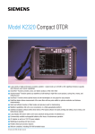
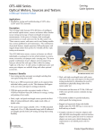
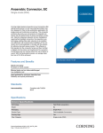
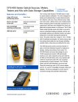
Model 340
OTDR Plus™ Multitester II
Corning
Cable Systems
Applications
• LAN
• Telco
• CATV
Description
Model 340 OTDR Plus™ Multitester II offers true multitesting
capability that features field-installable single-mode, multimode, and quad OTDR modules, visual fault locator, as well
as optional built-in power meter and laser source. The standard unit provides internal solid-state memory for 125 traces
and a floppy disk drive. An optional hard drive is also offered
to allow mass data storage and speeds testing by eliminating
the need to constantly exchange floppy disks in the standard
drive. The product line offers a large variety of high-performance multimode and single-mode modules featuring a superior
single-mode unit with 46 dB dynamic range. SoftView™ emulation software provides desktop analysis and quality documentation capability.
Model 340 OTDR Plus Multitester II | Photo TEQ15
A large 10.4-inch (26.4 cm) display is easy to read and eliminates the need to jump from screen to screen to view results.
Because it is active matrix color, readability is further enhanced. The extraordinary strength, durability, and weather
resistance of the custom polymer housing protects your
equipment investment.
Troubleshooting with the 340 is quick and easy with the
SmartTest™ function. At the touch of a button, the 340 selects
the parameters and then tests the fiber. The DualTrace™ function tests and displays both wavelengths on one graph. The
multitasking operating system provides fast fiber analysis and
data collection. The DualPulse feature allows measurement of
the same fiber with two pulse widths to optimize resolution
and distance measurements.
Repetitive testing and documentation of each fiber is reduced
to the shortest possible time using the AutoIncrement™ function. Only one button per fiber is needed to record both a
trace and event table at both wavelengths. Pop-up dialog boxes
guide you from fiber-to-fiber and provide warnings if a fault of
above-threshold loss is found.
Sold by:
http://www.TWAcomm.com
Toll Free: (877) 892-2666
Product Specifications
Model 340
OTDR Plus™ Multitester II
Features / Benefits
• SmartTest™ function provides a fast, one-button analysis of
the entire fiber
• AutoIncrement™ function speeds up repetitive as-built testing in high-fiber count projects, saving time, money, and
reducing error
• DualTrace™ function shows optimal traces at both wavelengths on one graph for easy analysis
• Large variety of high-performance modules available – single-mode up to 46 dB to offers significant distance capacity
and enhances event search capabilities
• Multitest capabilities offer all-in-one convenience on a fieldupgradeable platform
• SoftView™ emulation software for batch printing and editing,
trace overlay, and bidirectional analysis
• Large display with active matrix color eases eyestrain during
periods of extended use
• Commercially available rechargeable batteries offer hours of
autonomous operation
• AC adapter as well as a 12V DC power adapter
• Multilingual operating and help screens
• Quick and efficient location of fiber breaks and previous
event for landmarking
• Flexible Universal Connector System
• Telcordia compliant, including GR-196 formatted traces
• Level 3 approved
Corning
Cable Systems
The Multitester C0ncept
The 340 combines single-mode, multimode, and
quad OTDR capabilities along with a power
meter, visual fault locator, and stabilized singlemode light source into a compact platform that
resides in a rugged polymer housing. Virtually any
field testing can be accomplished with the unit.
Capabilities include incoming reel inspections,
link loss measurements, fiber attenuation (dB/km),
splice and connector loss, reflectance and optical
return loss measurement, length measurement,
visual fault location, and a 2 kHz test tone for
fiber identification. With the many range and test
options available, the unit can be optimized for
LAN, telco, or CATV applications. Specialty
modules for water intrusion (1244 nm) S-band
(1410 nm) and out of band (1625 nm) testing are
also available. Because the platform is modular
and field-installed, OTDR and VFL options not
ordered initially can be added at a later date.
OTDR Functions
The 340 is two OTDRs in one – single-mode and
multimode – making it ideal for LAN testing,
where both fiber types are common. With up to
46 dB of single-mode range available, the 340 is a
powerful tool for telco and CATV applications as
well.
Power Meter
The built-in power meter options make end-toend testing easy because data can be saved to disk
and analyzed/printed with the same software used
for OTDR traces. For CATV applications, a range
of +20 dBm is available.
Visual Fault Locator
The field-installable VFL makes fault location
within the OTDR’s deadzone possible as well as
provides visual continuity checks.
Single-mode Source
Units equipped with single-mode OTDR capability can also be equipped to function as a stabilized
laser source for loss measurement.
Sold by:
http://www.TWAcomm.com
Toll Free: (877) 892-2666
Page 2
Model 340
OTDR Plus™ Multitester II
2 kHz Test Tone
Fiber identifiers such as the CheckPoint™ and CheckPoint
Plus can recognize this tone to locate a fiber at a splice or
repair point.
Fault Locate Function
The OTDR operates as a simple fault locator. At the touch
of a button, the unit quickly and accurately finds the end of
the fiber.
SmartTest™ Function
Think of the SmartTest function as the built-in expert. One
key press will select the best parameters for the connected
fiber, acquire the data, and present both a trace and an event
table on one screen. Both novice and expert will benefit from
quick and complete fiber characterization. For the novice, getting good results requires only minimal equipment knowledge.
For the expert, the SmartTest function can quickly set
machine parameters.
DualTrace™ Function
On one screen, the DualTrace function characterizes a fiber at
both wavelengths, optimizing the pulse width for each. Visual
comparison of performance at each wavelength is greatly
enhanced by combining both traces into one graph. Wavelength-dependent losses, such as bending and pinching in
splice trays, tight bends in cable placement, and compression
due to temperature extremes, are also easier to identify in the
DualTrace function view. Such events will exhibit greater loss
at the longer wavelength, both on the traces and in the event
table.
Corning
Cable Systems
AutoIncrement™ Function
Documentation of new installations and repairs is
performed quickly with AutoIncrement function.
This function can create traces and event tables at
both wavelengths, save them to disk, and prompt
the user for the next fiber when ready. If any unacceptable losses are detected, the user is informed
before proceeding. Sequential file names are automatically incremented for each fiber in the test.
Data Storage
Data is stored to either the internal solid-state
memory, a standard floppy drive, or an optional
hard drive. Over 80,000 traces can be stored on
the internal hard drive. Floppy disks may be created directly from the hard drive. Data can also be
stored in other compatible file formats such as the
standard Telcordia GR-196 format.
PC Emulation Software
SoftView™ emulation software turns a notebook or
office PC into a fiber analysis workstation with
powerful batch printing, reporting, and editing
tools. Virtually all the functions available on the
OTDR are available on the PC for data stored to
disk. SoftView emulation software provides manual operation with view trace, 8 trace compare,
Telcordia GR-196 formatted trace measurement,
save, and recall, plus fast analysis and batch printing, fast templates, bidirectional analysis, and
global processing.
DualPulse Function
A fiber is tested at a single wavelength with two pulse widths.
Two traces are displayed, one for each pulsewidth. The short
pulse provides optimal event resolution, while the longer pulse
provides excellent distant measurements.
Sold by:
http://www.TWAcomm.com
Toll Free: (877) 892-2666
Page 3
Model 340
OTDR Plus™ Multitester II
Corning
Cable Systems
Specifications
Optical Modules
Multimode Modules
340M-40
340M-41
340M-42
Center Wavelength (±20 nm)
850 nm
1300 nm
850/1300 nm
Dynamic Range
23 dB
26 dB
23/26 dB
Attenuation Deadzone
6.5 m
7m
6.5/7 m
Single-mode Modules
340M-13
340M-14
340M-15
340M-23
340M-24
340M-25
Center Wavelength
1310 nm
± 20 nm
1550 nm
± 20 nm
1310/1550
20/± 20 nm
1310 nm
± 20 nm
1550 nm
± 20 nm
1310/1550
± 20 nm
Dynamic Range
30 dB
28 dB
30/28 dB
36 dB
34 dB
36/34 dB
Attenuation Deadzone
10 m
12 m
10/12 m
10 m
12 m
10/12 m
Single-mode Modules
340M-34
340M-36
340M-38
340M-39
340M-61
340M-62
Center Wavelength (±20 nm)
1550 nm
1310/1550 nm
1550 nm
1310/1550 nm 1244 nm
1244/1310 nm
Dynamic Range
40 dB
40/40 dB
46 dB
43/46 dB
36 dB
36/36 dB
Attenuation Deadzone
6m
6m
10 m
10/10 m
6m
6/9.5 m
Single-mode Modules
340M-63
340M-64
340M-71
340M-72
340M-73
340M-74
340M-76
Center Wavelength (±20 nm)
1244/1550 nm 1244/1625 nm
1625 nm
1310/1625 nm 1550/1625 nm 1625 nm
1550/1625 nm
Dynamic Range
36/34 dB
36/36 dB
36 dB
36/36 dB
36/36 dB
40 dB
40/40 db
Attenuation Deadzone
6/11 m
6/7 m
7m
9.5/7 m
11/7 m
7m
11m/7m
Hybrid Multimode/
Single-mode Modules
340M-56
340M-57
340M-53
340M-54
Center Wavelength (±20 nm)
850/1300 nm 850/ 300 nm
1310/1550 nm 1310/1550 nm
1310/1550/1625 nm
1310/1410
1550/1625 nm
Dynamic Range
23/25 dB
22/21 dB
23/24 dB
33/31 dB
40/40/40 dB
36/36 dB
36/36 dB
Attenuation Deadzone
8/9 m
11/12 m
8/9 m
11/12 m
7/7/7 m
7/7 m
7/7 m
General Module Specifications
Parameter
Specification
Universal 2.5 mm Connector Types3
(Ultra PC standard)
(Angle PC available)
FC, ST ® Compatible, SC, D4, Biconic,
DIN 47256, SMA 905/906
Diamond HMS-0/HMS-10/HMS-10A, E-2000
Reflective Deadzone (typical)
3 m (multimode) / 3.5 m (single-mode)
Pulse width
(wavelength dependent)
4 ns to 10 µs (multimode); 10 ns to 30 µs (single-mode)
Spectral Width (RMS)
10 nm
Loss Resolution
0.001 dB
Distance Resolution
0.0001 km; 0.01 meters; 0.001 kft; 1ft; 0.0001 mi
Distance Sampling
0.25, 0.5, 1, 2, 4, 8, 16 meters (range dependent)
Distance Accuracy
0.0025% of distance measurement +/- distance resolution +/- index uncertainty
Laser Certification
CDRH class 1 requirements (eye safe) 21 CFR
For dynamic range SNR=1. All measurements are typical and made using FC/SPC @ 25°C.
2
Multimode: 62.5 µm with PC polish; single-mode: Ultra PC with Angle PC polish available.
3
For MT-RJ, use a hybrid patch cord.
1
Sold by:
http://www.TWAcomm.com
Toll Free: (877) 892-2666
Page 4
Model 340
OTDR Plus™ Multitester II
Corning
Cable Systems
Specifications
Mainframe and General Specifications
Parameter
Display Type
Units of Measure
Operating Temperature
Storage Temperature
Humidity
Maximum Altitude
Power Supply
Weight
Dimensions
Data Points
Tone for Fiber Identification
Mass Storage
Specification
10.4-inch Active Matrix Color (TFT)
Meters, Feet (selectable)
AC power: 0˚ to 45˚C (32˚ to 122˚F); Battery: 0˚ to 40˚C (32˚ to 104˚F)
-20˚ to +60˚C (-4˚ to 140˚F)
95% RH maximum, non-condensing
50,000 ft
Battery: 6 hr typical battery life-(2); recharge time: 1.5 to 2 hr;
AC: 100-250 V, 47-63 Hz; Autoranging: 12 V DC operation
11.0 lb (4.9 kg) includes battery and module
9.5 in x 13.5 in x 3.75 in (24.1 cm x 34.3 cm x 9.5 cm); includes mainframe, 1 module, and battery
Up to 16,000
2 kHz
Internal Solid-State Memory: up to 125 traces; floppy (included): 1.44 Mb, 3.5-inch;
hard drive (optional): over 80,000 traces
Visual Fault Locator Option
Parameter
Wavelength
Output Power
Transmission
Connector (fixed)
Laser Certification
Specification
635 ± 10 nm
≥ -2 dBm (0 dBm max)
CW or 2 Hz (blink)
FC, SC, or ST ® Compatible
IEC 825 Class 2, FDA (21CFR), Class 2
Single-mode Laser Source Option
Parameter
Wavelength
Output Power
Stability (+23°C, 8 hrs)
Spectral Width (RMS)
Modulation
Laser Certification
Specification
1310/1550 nm (same as module)
≥ -10 dBm, typical
± 0.2 dB
≤ 10 nm, typical
Continuous, 1 kHz, and 2 kHz
CDRH CLASS 1 21CFR requirements (eye safety)
Power Meter Option
Parameter
Calibrated Wavelengths
Optical Meter Range
(factory-installed)
Detector Type
Wavelength
Resolution
Store Reference Mode
Accuracy
Linearity
Specification
850/1300/1310/1550/1625* nm
Standard: +10 to -55 dBm
CATV: +20 to -45 dBm, with mf-460 filter
2 mm Ge PIN photodiode
800 - 1800 nm
0.01 dBm, 0.01% Watts
Yes
± 4% @ +5 to -50 dBm
± 8% @ +10 to +5 dBm and @ -50 to -55 dBm
± 0.04 dB, +5 to -55 dBm
* Does not apply to all meters
Sold by:
http://www.TWAcomm.com
Toll Free: (877) 892-2666
Page 5
Model 340
OTDR Plus™ Multitester II
Sold by:
http://www.TWAcomm.com
Toll Free: (877) 892-2666
Corning
Cable Systems
Ordering Information
The Model 340 OTDR Plus™ II Multitester product line offers maximum flexibility for getting the testing capability you need. To help
you get started, we combined our most popular configurations into kits for LAN, telco, and CATV applications. We offer three types of
kits: our all-inclusive Extra Deluxe Kit, our standard Deluxe Kit, and the economical Basic Kit. If none of the kit options meets your
needs, simply build your own multitester – line-by-line.
Extra Deluxe Kits
Extra Deluxe OTDR Plus Multitester Kits include the mainframe complete with hard drive, standard floppy drive, dual or quad OTDR
module of choice, power meter (standard +10 dBm/extended range +20 dBm measurement range), visual fault locator, and Softview ™
emulation software. Included in the kits are high quality test fiber boxes (one for each single-mode and/or one for multimode) and an
externally attached US Keyboard contained – packaged in the deluxe hard shell transit case. A variety of field-installable optics modules are
available for additional testing applications.
Part Number
340DXK-4210-XX
340DXK-1510-XX
340DXK-1520-XX
340DXK-2510-XX
340DXK-2511-XX
340DXK-2520-XX
340DXK-3610-XX
340DXK-3620-XX
340DXK-3820-XX
340DXK-5610-XX-XX 1
340DXK-5710-XX-XX 1
340DXK-5711-XX
Description
Dual multimode (23/26 dB)
Short range dual single-mode (30/28 dB)
CATV Short range single-mode (30/28 dB)
Mid range dual single-mode (36/34 dB)
Mid range dual single-mode (36/34 dB) with single-mode source
CATV Mid range dual single-mode (36/34 dB)
Long range dual single-mode (40/40 dB)
CATV Long range dual single-mode (40/40 dB)
CATV Long range dual 1550 nm single-mode (46 dB)
Dual multimode (23/25) + single-mode (22/21 dB)
Dual multimode (24/27) + single-mode (32/30 dB)
Dual multimode (23/24) + single-mode (33/31 dB) with single-mode source
Additional Extra Deluxe Kits available. Call Corning Cable Systems Customer Service at 1-800-743-2675 for more details.
XX = connector type: see connector code ordering information.
1
For kits with dual multimode and dual single-mode OTDRs, the first “XX” designates the multimode OTDR, power meter, and VFL connector type.
Deluxe Kits
Deluxe OTDR Plus Multitester Kits include the mainframe with standard floppy drive, hard drive, dual or quad OTDR of choice, power
meter, visual fault locator, and SoftView emulation software – packaged in the deluxe hard shell transit case. A variety of field-installable
optics modules are available for future upgrading.
Part Number
340DK-4210-XX
340DK-1510-XX
340DK-1520-XX
340DK-2510-XX
340DK-2520-XX
340DK-3610-XX
340DK-3620-XX
340DK-3820-XX
340DK-5610-XX-XX 1
340DK-5710-XX-XX 1
Description
Dual multimode (24/27 dB)
Short range dual single-mode (30/28 dB)
CATV Short range single-mode (30/28 dB)
Mid range dual single-mode (36/34 dB)
CATV Mid range dual single-mode (36/34 dB)
Long range dual single-mode (40/40 dB)
CATV Extended range single-mode (40/40 dB)
CATV Long range dual 1550 nm single-mode (46 dB)
Dual multimode (24/27) + single-mode (22/22 dB)
Dual multimode (24/27) + single-mode (32/30 dB)
XX = connector type: see connector code ordering information.
1
For kits with dual multimode and dual single-mode OTDRs, the first “XX” designates the multimode OTDR, power meter, and VFL connector type.
Basic Kits
Basic OTDR Plus Multitester Kits are for customers that desire minimum OTDR capability. The kit includes the mainframe with standard floppy drive, dual or quad OTDR of choice, SoftView emulation software, and the hard shell transit case. Field-installable optics
modules and VFL are available to upgrade your unit in the future.
Part Number
340BK-4200-XX
340BK-1500-XX
340BK-2500-XX
340BK-3600-XX
340BK-3800-XX
340BK-5600-XX-XX1
340BK-5700-XX-XX1
Description
Dual multimode (24/27 dB)
Short range dual single-mode (30/28 dB)
Mid range dual single-mode (36/34 dB)
Long range dual single-mode (40/40 dB)
CATV Extended range 1550 nm single-mode (46 dB)
Dual multimode (24/27) + single-mode (22/22 dB)
Dual multimode (24/27) + single-mode (32/30 dB)
XX = connector type: see connector code ordering information.
1
For kits with dual multimode and dual single-mode OTDRs, the first “XX” designates the multimode OTDR, power meter, and VFL connector type.
Page 6
Model 340
OTDR Plus™ Multitester II
Corning
Cable Systems
Ordering Information
Build Your Own Multitester
If none of the kit configurations meets your requirements, build your own! The large variety of optics modules, options, specialty modules,
and accessories allows configuration of your own custom unit. Follow the steps below to build your OTDR Plus™ Multitester.
Step 1:
Step 2:
Step 3:
Step 4:
Step 5:
Step 6:
Select a Mainframe with or without a hard drive.
Select an Optics Module with or without power meter and/or light source options.
Select a Transit Case - a soft case or hard shell case.
If desired, select SoftView™ emulation software.
If desired, select Visual Fault Locator (VFL).
If desired, select Accessories.
Step 1: Mainframe
Multitester Mainframe includes color monitor, floppy drive, AC power cord, and SoftView OTDR emulation software that provides
manual operation, view trace, two trace compare, and GR-196 measurements
340 - ■
1
1
Select hard drive option.
0 = Without hard drive
1 = With hard drive
2 = Hard drive with Win95 preloaded
Step 2: Optics Module (a la carte)
The power meter, single-mode light source, and visual fault locator options are offered in the plug-in optics module. To order one or all of
these items, order the following part number:
340M - ■ ■ ■ ■ - ■ ■ - ■ ■
1
2
3
4
2
1
Select OTDR option.
13 = 30 dB, 1310 nm, single-mode
module
14 = 28 dB, 1550 nm, single-mode
module
15 = 30/28 dB, 1310/1550 nm, dual
single-mode
23 = 36 dB, 1310 nm, single-mode
module
24 = 34 dB, 1550 nm, single-mode
module
25 = 36/34 dB, 1310/1550 nm, dual
single-mode
34 = 40 dB, 1550 nm, single-mode
module
36 = 40/40 dB, 1310/1550 nm, dual
single-mode
38 = 46 dB, 1550 nm, single-mode
module
39 = 46/46 dB, 1310/1550 nm, dual
single-mode
40 = 24 dB, 850 nm, multimode
module
41 = 27 dB, 1300 nm, multimode module
42 = 24/27 dB, 850/1300 nm, dual multimode
53 = 40/40/40 dB, 1310/1550/1625 nm,
single-mode tri module
54 = 36/36/36/36 dB, 1310/1410/1550/1625 nm,
single-mode quad module
56 = 24/27 dB, 850/1300 nm, multimode,
22/22 dB, 1310/1550 nm,
single-mode quad module
57 = 24/27 dB, 850/1300 nm, multimode,
32/30 dB, 1310/1550 nm, single-mode
quad module
61 = 36 dB, 1244 nm, single-mode
62 = 36/36 dB, 1244/1310 nm, dual single-mode
63 = 36/34 dB, 1244/1550 nm, dual single-mode
64 = 36/36 dB, 1244/1625 nm, dual single-mode
71 = 36 dB, 1625 nm, single-mode
72 = 36/36 dB, 1310/1625 nm, dual single-mode
73 = 36/36 dB, 1550/1625 nm, dual single-mode
74 = 40 dB, 1625 nm, single-mode
76 = 40/40 dB, 1550/1625 nm, dual single-mode
Select power meter and/or
light source option(s).
00 = optics module only
10 = optics module with +10 dB
power meter
20 = optics module with +20 dB
power meter
01 = optics module with single-mode
source (only available on singlemode OTDRs)
11 = optics module with source
and +10 dB power meter
21 = optics module with source
and +20 dB power meter
Note: Power meter and single-mode light source have the same connector type as the OTDR. For
OTDRs with quad modules, the power meter has the same connector type as the multimode OTDR.
Sold by:
(continued on next page)
http://www.TWAcomm.com
Toll Free: (877) 892-2666
Page 7
Model 340
OTDR Plus™ Multitester II
Corning
Cable Systems
Ordering Information
(continued from previous page)
3
Select connector code for single-mode OTDR connector type or multimode OTDR connector type on quad OTDRs.
50 = Diamond HMS-10/A
73 = ST compatible Angle
10 = Biconic
30 = ST ® compatible
15 = D4
35 = SC
60 = FC Angle
80 = Diamond E-2000
20 = SMA 905/906
40 = Diamond HP HMS-10
65 = SC Angle
85 = DIN
25 = FC
45 = Diamond HMS-0
70 = DIN Angle
90 = Diamond GFS-3
4
Select connector code for Quad OTDRs, single-mode connector type.
10 = Biconic
30 = ST compatible
50 = Diamond HMS-10/A
15 = D4
35 = SC
60 = FC Angle
20 = SMA 905/906
40 = Diamond HP HMS-10
65 = SC Angle
25 = FC
45 = Diamond HMS-0
70 = DIN Angle
73 = ST compatible Angle
80 = Diamond E-2000
85 = DIN
90 = Diamond GFS-3
Step 3: Transit Case
Part Number
340-CASE-DLX
340-CASE-SFT
Description
Deluxe Hard-Shell Transit Case with wheels and collapsible handle
Deluxe Soft Carry Case with extra storage compartments
Step 4: SoftView™ Emulation Software (optional)
Part Number
SOFTVIEW
Description
Manual Emulation Operation with view trace, 8 trace compare, Telcordia GR-196 formatted trace
measurement, save, and recall, plus fast analysis and batch printing, fast templates, bidirectional analysis,
and global processing
Step 5: Visual Fault Locator – VFL (optional)
Part Number
340-VFL-XX
Description
635 nm Visual Fault Locator; XX = Connector Type: ST = ST compatible; SC = SC; FC = FC
Step 6: Accessories (optional)
Part Number
ACCESSORIES
Description
Please see Accessories ordering information
Example
To order an OTDR Plus™ Multitester with hard drive, 1310 nm (36 dB) single-mode OTDR with a standard power meter, field-installable
VFL, ST compatible connectors, Softview software, soft transit case, and a single-mode test fiber box:
Steps
Step 1:
Step 2:
Part Number
340-1
340M-2310-30
Step 3:
Step 4:
Step 5:
Step 6:
340-CASE-SFT
SOFTVIEW
340-VFL-ST
340-TFBS-ST-ST
Description
Mainframe with hard drive
1310 nm single-mode (36 dB), ST compatible,
with standard +10 dBm power meter
Soft Case
Emulation Software (optional)
635 VFL with PM, ST compatible (optional)
OTDR Test Fiber Box, single-mode, ST compatible (optional)
Sold by:
http://www.TWAcomm.com
Toll Free: (877) 892-2666
Page 8
Model 340
OTDR Plus™ Multitester II
Corning
Cable Systems
Ordering Information
Accessories
Part Number
340-CASE-DLX
340-CASE-SFT
340-PRINTER
340-PAPER-R
340-TRIPOD
340-BATT
340-AC-POWER
340-AUTO
340-SERIAL-FF
340-SERIAL-FM
340-KEY-US
340-KEY-GE
340-KEY-FR
340-KEY-SP
340-KEY-IT
FOB-MANUAL
340-MANUAL
340-TFBM-MTRJ-XX*
340-TFBS-MTRJ-XX*
340-PARALLEL
340-WARRANTY-1
340-WARRANTY-2
340-AC-US/J
340-AC-EUROPE
340-AC-UK
340-AC-SWISS
340-AC-ITALY
340-AC-AUSTRALIA
340-CHINESE
340-MF-460
Description
Deluxe Hard-Shell Transit Case with wheels and collapsible handle
Deluxe Soft Carry Case with extra storage compartments
Thermal Printer with cable
Printer Paper (10 rolls/pk)
Tripod
Replacement 12 V Battery
Replacement AC Adapter/Charger (US)
Auto Adapter and Charger
Serial Cable Null 9F to 9F
Serial Cable 9F to 9M
US Keyboard
German CE Keyboard
French CE Keyboard
Spanish CE Keyboard
Italian CE Keyboard
340 Training Manual
340 User’s Manual
Multimode MT-RJ Test Fiber Box (launch cable) 300 feet/91 meters – XX = ST ® compatible, SC, or FC
Single-mode MT-RJ Test Fiber Box (launch cable) 1,000 feet/305 meters – XX = ST compatible, SC, or FC
Parallel Cable DB25M to DB25M
Additional 1-year Warranty includes one calibration; must be ordered at time of purchase
(not sold after shipment)
Additional 2-year Warranty includes two calibrations; must be ordered at time of purchase
(not sold after shipment)
AC Power Cord for US and Japan
AC Power Cord for Europe
AC Power Cord for United Kingdom
AC Power Cord for Switzerland
AC Power Cord for Italy
AC Power Cord for Australia
Chinese Language Option (mainframe)
10 dB Power Meter Filter
*Other connector types available upon request.
Sold by:
http://www.TWAcomm.com
Toll Free: (877) 892-2666
Page 9
Model 340
OTDR Plus™ Multitester II
Corning
Cable Systems
Ordering Information
Optical Module Options/Accessories
Visual Fault Locator (field-installable option)
340-VFL-FC module
340-VFL-ST compatible module
340-VFL-SC module
OTDR / Source Universal Adapter (One included with each module; quad includes two.)
XX Connector
Connector
Codes1
Type
10
Biconic
15
DA
20
SMA 905/906
25
FC
30
ST® Compatible
35
SC
40
Diamond HP HMS-10
45
Diamond HMS-0
50
Diamond HMS-10/A
60
FC Angle Connector Adapter
65
SC Angle Connector Adapter
70
DIN/HRL -10 Angle Connector Adapter
73
ST Compatible Angle Connector Adapter
80
Diamond E-2000 Angle Connector Adapter
85
DIN 47256
–
FDDI
90
Diamond GFS-3
OTDR
Adapters
UA-10
UA-15
UA-20
UA-25
UA-30
UA-35
UA-40
UA-45
UA-50
UA-60
UA-65
UA-70
UA-73
UA-80
UA-85
—
—
Power Meter
Adapters
MA-10
MA-15
MA-20
MA-25
MA-30
MA-35
MA-40
MA-45
MA-50
MA-60
MA-65
MA-70
MA-73
MA-80
MA-85
MA-00
MA-90
For LC and MT-RJ connectors, use hybrid test fiber boxes.
1
Sold by:
http://www.TWAcomm.com
Toll Free: (877) 892-2666
Page 10
Model 340
OTDR Plus™ Multitester II
Corning
Cable Systems
Sold by:
http://www.TWAcomm.com
Toll Free: (877) 892-2666
Page 11
Model 340
OTDR Plus™ Multitester II
Corning
Cable Systems
Sold by:
http://www.TWAcomm.com
Toll Free: (877) 892-2666
Corning Cable Systems LLC • PO Box 489 • Hickory, NC 28603-0489 USA
1-800-743-2675 • FAX: +1-828-901-5973 • International: +1-828-901-5000 • http://www.corning.com/cablesystems
Corning Cable Systems reserves the right to improve, enhance, and modify the features and specifications of Corning Cable Systems’ products
without prior notification. Discovering Beyond Imagination is a trademark of Corning Incorporated. ST is a registered trademark of Lucent
Technologies, Inc. AutoIncrement, CheckPoint, DualTrace, OTDR Plus, SmartTest, and SoftView are trademarks of GN Nettest (New York) Inc. All
other trademarks are the properties of their respective owners. Corning Cable Systems is ISO 9001 certified. © 1998, 2002 Corning Cable Systems.
All rights reserved. Published in the USA. TEQ-62-EN / April 2002 / 7.25M