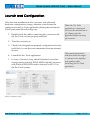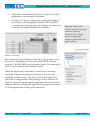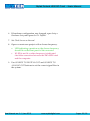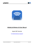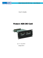
1
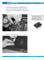
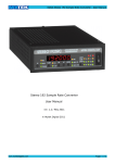
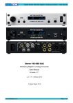
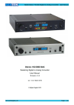
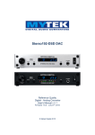
Mytek Protools-HDX DIO Card – User's Manual
User's Guide
Protools HDX DIO Card
ver. 2.1 / Jan 2015
© Mytek 2015
Mytek Protools-HDX DIO Card – User's Manual
This manual may be updated at any time.
To download the latest version, technical support, and for setup tips
please visit:
http://www.mytekdigital.com
Contact Mytek tech support at:
[email protected]
or at:
tel. +1 (347) 384-2687
Mytek Digital
148 India St. 1Fl
Brooklyn, NY 11222
USA
Digidesign/Avid Pro Tools ® is a trademark of Digidesign/Avid
Mytek Protools-HDX DIO Card – User's Manual
Content
Content..............................................................................3
Introduction......................................................................4
Before You Begin..............................................................4
Quick Start.........................................................................5
Card Installation...............................................................7
Connecting Clock Signal Line.......................................12
Input Connection............................................................14
Signal Routing................................................................15
Master/Slave mode.........................................................17
Backward compatibility mode .....................................17
Launch and Configuration............................................18
Typical Configurations..................................................20
Software update..............................................................27
User Manual ver. 2.1 / Jan 2015
www.mytekdigital.com
Page: 3 / 32
Mytek Protools-HDX DIO Card – User's Manual
Introduction
The Mytek Protools-HDX DIO Card is a physical card which
plugs into the back of the Mytek 8X192 ADDA converter.
With this card installed the Mytek 8X192 ADDA can be directly
connected to the HDX or HD Native (Core, Process or Accel in
backward compatibility mode) interface cards of Avid Pro Tools
HD ® systems .
The card may be installed by the user as described further in the
manual. The 8X192ADDA with the card installed will be
recognized by Pro Tools HD® software as an emulated HD I/O
interface (Digidesign/Avid 192 I/O interface in backward
compatibility mode).
Before You Begin
Before connecting the DIO-HDX card check if the most current
firmware (version 4.5.8 or later) is installed in the
8X192 converter. To verify the version locate the 8 pin firmware
chip in a socket on the main converter board (near heatsink), or
please contact Mytek for additional assistance.
(If necessary contact Mytek to request appropriate free
firmware eprom chip.)
User Manual ver. 2.1 / Jan 2015
www.mytekdigital.com
Page: 4 / 32
Mytek Protools-HDX DIO Card – User's Manual
Quick Start
1. DIO-HDX card installation
Remove the top cover from the converter, unscrew
DIOCARD1 slot plate (first slot from the right while looking
at the rear panel) and install the DIO-HDX card using
provided screws. Double check that all the connector pins
match properly with the pins of the connector on the main
converter board. Check that dip switches are in the off
position (for more information about dip switches function
go to page 17).
2. Connecting the card to Pro Tools HDX ® system
Remember to turn off
power, and disconnect
power and signal cables
while working with the top
cover removed.
The Pro Tools card must be connected to the Primary Port of
the DIO-HDX card. Protools card theoretically supports
only two devices connected to one port (which can be of
different brands), but a new feature of DIO-HDX card
allows to use a couple of 8X192ADDA as one 16 channel I/O
device, thus making it possible to use four Mytek converters
connected to one HDX port. For more information please
read master/slave mode section of this manual. In the case of
using more than one converter, the next one should be daisy
chained from the Expansion Port of the first converter to the
Primary Port of the next. In other words 4 Mytek
8X192ADDs can be daisy-chained off one HDX port. (Only 2
Mytek 8X192ADDAs could have been daisy-chained of the
PREVIOUS older Mytek HD Card)
3. Connecting the clock signal
The first converter in the Pro Tools system must operate on
internal clock and is the system clock master. We
recommend always making Mytek the master as it
incorporates a superior clock generator with multiple
wordclock outputs. When a 192 I/O Digidesign interface is
connected in the slave configuration, WCK on the front
panel of Mytek converter must be set to FS/4 (which means
that wordclock is 48k for 48k FS, 48k for 96k FS and 48k for 192k
FS, 441.k for 44.1k and so on)
User Manual ver. 2.1 / Jan 2015
www.mytekdigital.com
Turn down the amplifier
and speakers connected to
the computer while
launching the Pro Tools
application.
Page: 5 / 32
Mytek Protools-HDX DIO Card – User's Manual
5. Hardware Setup Configuration
In Protools software choose Setup > Hardware Setup and
check sampling frequency, clock signal (should be set to
Internal) and confirm Input and Output interfaces are
present. Every converter in the menu should be Set to
Default.
6. Routing configuration within converters
The Mytek 8X192 ADDA SOURCE TO DIGITAL OUT
defines sources of audio signals that are sent from the
converter to the Pro Tools system and all other digital
outputs (all digital outputs are simultaneous). SOURCE TO
ANALOG OUT defines sources of audio signals that are
transmitted to the DAC in the converter.
Remember that 8x192
ADDA converter has eight
channels. For more
information read
master/slave mode section
in this manual.
6. I/O signal configuration
In Setup > I/O Setup you can assign signal sources to
interfaces.
7. Input selection – start of recording
Choose preconfigured inputs and outputs in Pro Tools, test
record, and then playback of selected audio tracks.
User Manual ver. 2.1 / Jan 2015
www.mytekdigital.com
Page: 6 / 32
Mytek Protools-HDX DIO Card – User's Manual
Card Installation
Only a single Protools-HDX DIO Card can be installed in one
converter. A different format card can be installed in the second
slot. The HDX DIO card must be installed in the DIOCARD1
slot, which is first from the right at the converter’s rear panel.
8x192 ADDA converter’s rear panel
WARNING!
Remember to follow basic safety rules about handling of
electronic devices while opening the converter:
✔ keep your hands dry,
✔ turn off power and detach power and signal cables
while working with the top cover removed.
To install DIO-HDX card:
1. Locate the DIOCARD1 expansion slot on the
motherboard
2. Check if the power cord and all signal and clock lines
are disconnected.
User Manual ver. 2.1 / Jan 2015
www.mytekdigital.com
Before you install the card
in the converter, check if
converter’s firmware
supports DIO-HDX card
(version v.4.5.8 or later). If
not, contact Mytek to
request current version.
Page: 7 / 32
Mytek Protools-HDX DIO Card – User's Manual
3. Remove top cover.
4. Locate the DIOCARD1 expansion slot on the
motherboard.
User Manual ver. 2.1 / Jan 2015
www.mytekdigital.com
Page: 8 / 32
Mytek Protools-HDX DIO Card – User's Manual
5. Unscrew cover plate of DIOCARD1 slot from the rear
panel.
6. Partially insert the card from the back of the converter.
User Manual ver. 2.1 / Jan 2015
www.mytekdigital.com
Page: 9 / 32
Mytek Protools-HDX DIO Card – User's Manual
7. Attach card ribbon cable to DIOCARD1 connector on the
mainboard.
8. Gently push the card inside and secure it using four
screws
User Manual ver. 2.1 / Jan 2015
www.mytekdigital.com
Page: 10 / 32
Mytek Protools-HDX DIO Card – User's Manual
9. Screw in converter top cover.
10. Connect power and signal lines.
11. Turn the converter on.
After boot up (which takes approx 20 sec) converter will switch
to regular mode, and Protools-HDX DIO Card (DIOCARD1)
can now be selected as signal source.
User Manual ver. 2.1 / Jan 2015
www.mytekdigital.com
Page: 11 / 32
Mytek Protools-HDX DIO Card – User's Manual
Connecting Clock Signal Line
Single converter
If a single converter is used in the system, choosing internal
clock is the best solution. If external clock is used for
synchronization, SAMPLE RATE must be set to EXT. To do this,
press and hold EXT CLOCK SOURCE switch.
Regardless of synchronization source, choose in Pro Tools
software: Setup > Hardware Setup and select Internal on the Clock
Source tab.
Setup > Hardware Setup
Master 8x192 ADDA converter’s front panel
Clock source is typically internal, choose external only if you must use it
for systemic reasons.
Check if the selected sampling frequency of the converter (FS)
matches the sampling frequency in Pro Tools. If FS is double or
quadruple of external clocks frequency, WCK option must be set
to FS/4. FS/4 is the default setting and must be used whenever
multiple Digidesign I/O units are used in addition to master
8X192ADDA.
File > New Session
User Manual ver. 2.1 / Jan 2015
www.mytekdigital.com
Page: 12 / 32
Mytek Protools-HDX DIO Card – User's Manual
Multiple converters
A Pro Tools HD system can accept up to two converters
connected to each port. Mytek DIO-HDX card allow to use four
converters connected to one HD system port – for more
information please read master/slave mode section in this
manual. Various brands can be mixed as long as they are all
capable of emulating the Avid I/O interface. If multiple
converters are used, one serves as a source of the clock signal
(Master), with the rest of the devices receiving it (Slave).
Our recommended setup is to use the Mytek 8X192ADDA as
the clock source feeding all other converters from multiple
wordclock outputs to all slave devices in a star configuration.
8X192 ADDA converter has 6 clock outputs. Clock signal
originates from the very precise CX797 module. Because of
that 8X192 ADDA converter is the best clock signal source
in the majority of multiple devices configurations
In system with multiple
units, double check that the
configuration of clock signal
lines, synchronization
sources and sampling
frequencies of all converters
in the system are correct.
Correct clock configuration
is necessary for proper
operation of converters and
for best sound quality.
Make 1st Mytek in the chain
the clock master for the
whole studio. There is no
benefit of using a dedicated
house clock generator.
Clocking off Mytek internal
clock generator produces
superior results because the
clock and clock line high
current drivers are the best
in the industry.
Changing external
synchronization source
while the program is
running may result in
improper operation of
converters and loud cracks
in the analog section.
Wordclock connections in a Pro Tools HD system with 3 Mytek 8X192
ADDAs
User Manual ver. 2.1 / Jan 2015
www.mytekdigital.com
Page: 13 / 32
Mytek Protools-HDX DIO Card – User's Manual
Input Connection
The Protools DIO-HDX card features two connectors: Primary
Port and Expansion Port. Functionality of these connectors is
identical to Pro Tools system. Up to 4 8X192 ADDA Mytek
Digital converters can be daisy chained or mixed with Avid HD
I/O and other brands that emulate HD I/O.
Output connectors on the back of Ptools-HDX-DIO card.
Setup > Hardware Setup
Protools computer interface card should always be connected to
the Primary Port in the Master device, which operates as a clock
signal source. Then, Expansion Port can be connected with
Primary Port of a different Slave device. Devices are visible in
Setup > Hardware Setup menu of the Pro Tools application.
User Manual ver. 2.1 / Jan 2015
www.mytekdigital.com
Page: 14 / 32
Mytek Protools-HDX DIO Card – User's Manual
Signal Routing
While Pro Tools software allows up to 16 channels of input or
output, only 8 inputs and outputs are active when single Mytek
8X192 ADDA is used. If two Mytek converters are set to work in
master/slave mode they are detected as one 16 channel
converter.
Input
Audio signals transmitted from the 8X192 ADDA converter
originate from the source selected by the switch SOURCE TO
DIGITAL OUT. If ANALOG is selected, 8 analog channels will
show up as inputs in Pro Tools software. If AES/EBU is selected,
8 digital channels will be present as inputs (only 4 if dual wire
AES/EBU mode (for 192k) is used!). Similarly other types of
digital inputs depending on the second DIO CARD2 installed
can also be used. If DIO CARD1 is selected as input, signal
output from Pro Tools will be routed back into Pro Tools inputs.
The actual signal flow in the 8X192ADDA is available in a form
of schematics in the 8X192ADDA manual.
After selecting channel sources in the converter, you can choose
channels selected for recording in the Pro Tools application. In
Setup > I/O Setup you can freely assign track sources to each
interface channels and then assign them to particular tracks.
Editing panel – selecting
interfaces' input
Setup > I/O Setup
User Manual ver. 2.1 / Jan 2015
www.mytekdigital.com
Page: 15 / 32
Mytek Protools-HDX DIO Card – User's Manual
Output
Editing panel – assigning output
channels
To playback signal from Pro Tools to the converter's analog
outputs DIOCARD 1 SOURCE TO ANALOG OUT should be
selected. If SOURCE TO DIGITAL OUT is set to DIOCARD1 as
well audio is relayed from the Pro Tools system to the converter
DAC (analog out) and to AES/EBU outputs as well as other
digital outputs if installed.
The actual signal flow in the 8X192ADDA is available in the
form of schematics in the 8X192ADDA manual.
The Pro Tools tracks to be sent to the 8X192 ADDA can be
selected in the Pro Tools software. In Setup > I/O Setup you can
assign interfaces to signal outputs, later assigned to tracks in the
Pro Tools application.
While track outputs are assigned to channels in the Pro Tools
software, the actual signal routing of the incoming 8 channels to
the converter's physical inputs and outputs must be done
manually on the converter front panel ( SOURCE TO ANALOG
OUT and SOURCE TO DIGITAL OUT). This routing may
initially appear confusing, but after studying the signal flow
diagram in the 8X192ADDA manual you will find it makes a lot
of sense by providing very useful system flexibility.
User Manual ver. 2.1 / Jan 2015
www.mytekdigital.com
Page: 16 / 32
Mytek Protools-HDX DIO Card – User's Manual
Master/Slave mode
Mytek DIO-HDX card allow to use two 8x192ADDAs as one 16
channels device. Mytek HDX card is factory preset to auto
detect next daisy-chained converter, set it to slave mode (first
card is master) and reroute channels 9 to 16 to the next daisychained card. Slave converter isn't detected in Pro Tools system,
it only expands first Mytek to show up as single 16 channel
device (fully functional as such for routing, playing and
recording). 3rd Mytek 8X192ADDA converter in the chain is
recognized by software as the second Digidesign/Avid HD I/O,
as working in master mode and subsequent 4th Mytek
8X192ADDA will be auto detected like as additional channels
#24-32).
In master mode next device
will be used as slave and it
can't be detected by Pro
Tools system. If next device
isn't DIO-HDX card it
can't be slave and it isn't
working. To use that device
after single DIO-HDX card
set 1st and 3rd dip switches.
This configuration works flawlessly, if all daisy chained
converters are Mytek 8x192ADDAs. Using another branded
devices in the same daisy chain with Mytek DIO-HDX card can
cause problems if the card is set to auto detect). In mixed
devices configuration it is recommended to set DIO-HDX card
to be master, slave or single card manually, using dip switches
on the card:
•
1st dip switch turned on – device is master
•
all dip switches turned off - device is slave, autodetect
mode
•
1st 2nd dip switches turned on - device is slave
•
1st 3rd dip switches turned on – standalone mode, next
device is detected by Pro Tools
User Manual ver. 2.1 / Jan 2015
www.mytekdigital.com
Page: 17 / 32
Mytek Protools-HDX DIO Card – User's Manual
Backward compatibility mode with
older HD systems.
To use DIO-HDX card with old Pro Tools system (core, process
and accel cards) it is necessary to set DIO-HDX in backward
compatibility mode. In this mode DIO-HDX is detected as
Digidesign 192 I/O, but it isn't compensated and second
converter is visible as digital Inputs and Outputs.
To set it – turn 4th dip switch on. The Avid Digilink HD>HDX
adapter cable should be used to connect Mytek DIO-HDX card
to older Protools HD systems.
User Manual ver. 2.1 / Jan 2015
www.mytekdigital.com
Page: 18 / 32
Mytek Protools-HDX DIO Card – User's Manual
Launch and Configuration
After the card installation in the converter, and after each
hardware configuration change, interface controls must be
configured in the Pro Tools application during the first launch.
This is performed the following way:
1. Double check the cables connecting the converter with
the Pro Tools card are properly attached.
When the Pro Tools
application is running do
not turn the converter on or
off. Always quit the
application before turning
off converter.
2. Turn the converter on.
3. Check if clock signals are properly configured and active
(solid lock, in case they are transmitted from an external
device).
4. Launch the Pro Tools application.
5. In Setup > Hardware Setup check if attached converters
were properly detected. 8X192 ADDA Mytek Converter
with Protools DIO-HDX card is detected as HD I/O in
the Pro Tools system.
Take special precautions
and turn down the output
or volume to the amplifier
and speakers while
launching the Pro Tools
application.
Setup > Hardware Setup
User Manual ver. 2.1 / Jan 2015
www.mytekdigital.com
Page: 19 / 32
Mytek Protools-HDX DIO Card – User's Manual
6. Select each converter and press Set to Default to set the
application in the normal work mode.
7. In Setup > I/O Setup configure the routing according to
your needs, while keeping in mind the 8X192 ADDA
converter has only eight channels. If slave converter was
connected 16 analog channels are available.
Remember that 8x192
ADDA converter has eight
channels. Selecting
channels 9-16 as audio
sources using single
converter will result in no
signal (silence).
Setup > I/O Setup
If the converter is not attached to the Pro Tools systems, it can
be used as a standalone device as if no DIO-HDX card was
installed. The DIO-HDX card is disabled until it is connected to
the Pro Tools systems and computer works.
When the application is launched, control over converter’s
sampling frequency is assigned to software. It is the only
available option in Setup > Hardware Setup which influences
converter’s configuration. Other settings such as selection of
input or format of digital signal are ignored and should not be
changed. Before launching the application pay special attention
to clock signal source setting in the converter.
User Manual ver. 2.1 / Jan 2015
www.mytekdigital.com
Setup > Hardware Setup
Page: 20 / 32
Mytek Protools-HDX DIO Card – User's Manual
Typical Configurations
Single 8x192 ADDA converter
1. Connect the 8X192 ADDA (through Primary Port) to the
Pro Tools interface card in a computer.
2. Turn on the computer and converter.
3. Set the converter to work with internal clock.
✔
✗
EXT LED shouldn’t be lit.
If LED is lit, press and hold EXT CLOCK SOURCE
button.
4. Launch the Pro Tools application.
5. Open Setup > Hardware Setup and check:
✔
✔
✗
Is the 8X192 ADDA Mytek Digital converter
properly detected as 192 I/O?
Are input and output signals assigned in the Input
and Output tab?
If not, close the Pro Tools application, turn off the
converter and check connection between the HDXDIO card and the computer.
Setup > Hardware Setup
User Manual ver. 2.1 / Jan 2015
www.mytekdigital.com
Page: 21 / 32
Mytek Protools-HDX DIO Card – User's Manual
6. If hardware configuration was changed, open Setup >
Hardware Setup and press Set To Default.
7. Set Clock Source as Internal.
8. Open or create new project with a chosen frequency.
✔
✗
LED indicating operation on the chosen frequency
should lit on the front panel of the converter.
If LED is not lit or other frequency is indicated,
check the connection between the DIO-HDX card
and the computer.
9. Use SOURCE TO DIGITAL OUT and SOURCE TO
ANALOG OUT buttons to set the correct signal flow in
the system.
User Manual ver. 2.1 / Jan 2015
www.mytekdigital.com
Page: 22 / 32
Mytek Protools-HDX DIO Card – User's Manual
✔
✔
Use SOURCE TO DIGITAL OUT button to select
audio signals relayed from the 8X192 ADDA
converter to the Pro Tools system and converter’s
digital outputs.
Use SOURCE TO ANALOG OUT to select signals
relayed to converter’s analog outputs.
10. In Setup > I/O Setup configure the routing according to
your needs, keeping in mind that the 8X192 ADDA
converter has eight channels.
Setup > I/O Setup
File > New Session
User Manual ver. 2.1 / Jan 2015
www.mytekdigital.com
Page: 23 / 32
Mytek Protools-HDX DIO Card – User's Manual
11. In the editing panel assign input and output channels
according to the I/O Setup configuration and converter’s
front panel.
Editing panel – selecting input interfaces
Editing panel – selecting output interfaces
12. The converter is ready to work.
User Manual ver. 2.1 / Jan 2015
www.mytekdigital.com
Page: 24 / 32
Mytek Protools-HDX DIO Card – User's Manual
Two 8x192 ADDA converters, first on internal clock
(clock master), second as slave
1. Connect 8X192 ADDA converters to the Pro Tools card
in a computer.
✔
Computer should be connected to the Primary Port of
the first converter, while its Expansion Port should be
connected to the Primary Port of the second
converter.
2. Choose which converter will operate as a clock signal
source (Master).
3. Use a BNC cable to connect the clock signal output of
the Master converter to the clock input of the second
converter (Slave).
4. Turn on the computer and converters.
5. Set the Master converter to work with internal clock.
✔
✗
EXT LED should not be lit.
If LED is lit, press and hold EXT CLOCK SOURCE
button.
6. Set the Slave converter to work with the external clock.
✔
✗
Press and hold the EXT. CLOCK SOURCE button.
If EXT LED is lit and WCK LED flashes, check if
clock inputs and outputs in converters were
correctly connected and the same SAMPLE RATE
sampling frequency and WCK frequency split rate is
set in both converters.
7. Launch the Pro Tools application.
User Manual ver. 2.1 / Jan 2015
www.mytekdigital.com
Page: 25 / 32
Mytek Protools-HDX DIO Card – User's Manual
8. Open Setup > Hardware Setup and check:
✔
✔
✗
Are 8X192 ADDA Mytek Digital converters properly
detected as HD I/O?
Are signals input and output of each converter
assigned in the Input and Output tab?
If not, turn off the Pro Tools application and
converters and check the connections of clock signals
between converters as well as the connections
between DIO-HDX cards and with computer.
Setup > Hardware Setup
9. If the hardware configuration was changed, open Setup >
Hardware Setup and press Set To Default.
10. Set Clock Source as Internal.
11. Open or create new project with a chosen frequency.
✔
✗
LED indicating operation at the chosen frequency
should be lit on the front panel.
If LED is not lit or another frequency is indicated,
check the connection between DIO-HDX cards and
with the computer.
User Manual ver. 2.1 / Jan 2015
www.mytekdigital.com
Page: 26 / 32
Mytek Protools-HDX DIO Card – User's Manual
12. Use SOURCE TO DIGITAL OUT and SOURCE TO
ANALOG OUT buttons to set desired signal flow in the
system.
✔
✔
Use SOURCE TO DIGITAL OUT button to select
which audio signals are sent from the 8X192 ADDA
converter to the Pro Tools system and converter’s
digital outputs.
Choose the signal transmitted to converter’s analog
output by pressing SOURCE TO ANALOG OUT
button.
13. In Setup > I/O Setup configure the routing according to
your needs, keeping in mind that channels 9-16 are
routed to second DIO-HDX card.
Setup > I/O Setup
User Manual ver. 2.1 / Jan 2015
www.mytekdigital.com
Page: 27 / 32
Mytek Protools-HDX DIO Card – User's Manual
14. In the editing panel assign input and output channels,
according to the I/O Setup configuration and converter’s
front panel.
Editing panel – selecting input interfaces
Editing panel – selecting output interfaces
15. Converters are ready to work
User Manual ver. 2.1 / Jan 2015
www.mytekdigital.com
Page: 28 / 32
Mytek Protools-HDX DIO Card – User's Manual
Software update
WARNING!
Remember to follow basic safety rules about the handling of
electronic devices while opening the converter:
✔ keep your hands dry,
✔ remember to turn off power and disconnect power
and signal cables while working with the top cover
removed.
To perform firmware update of 8X192 ADDA converter:
1. Check if the power cord and signal and clock lines are
disconnected.
2. Remove the top cover.
User Manual ver. 2.1 / Jan 2015
www.mytekdigital.com
Page: 29 / 32
Mytek Protools-HDX DIO Card – User's Manual
3. Locate the memory socket on the converter main board.
4. Gently remove old memory chip.
To avoid damaging memory
pins, remove the chip
vertically. Retain old
memory chip.
User Manual ver. 2.1 / Jan 2015
www.mytekdigital.com
Page: 30 / 32
Mytek Protools-HDX DIO Card – User's Manual
5. Carefully insert new firmware EPROM chip in the
socket. The chip slot (pin1) should be matching the
socket slot ie must be facing the back of the unit. If
necessary, gently bend pins inward, to match the holes
in the slot.
During installation check
correct chip orientation.
Marks on chip and socket
must be on the same side.
6. Mount the top cover back.
User Manual ver. 2.1 / Jan 2015
www.mytekdigital.com
Page: 31 / 32
Mytek Protools-HDX DIO Card – User's Manual
7. Attach power cord and other cabling.
8. Turn on the converter.
For about 2 seconds no LED's should be lit on the
converter’s front panel, as new software is copied from
memory to the main board chips. Then, all LED's should
turn on momentarily for about 10-20sec, and subsequently
the unit should begin normal operation.
The Protools HDX DIO card also contains a similar
EPROM memory chip that may require future upgrades
should such a need arise due to Pro Tools software
revisions or implementation of additional features.
Check Mytek webpage for information on the latest
firmware versions.
www.mytekdigital.com
User Manual ver. 2.1 / Jan 2015
www.mytekdigital.com
Page: 32 / 32