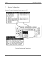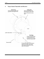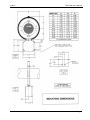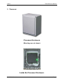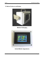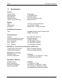
1
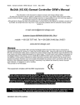
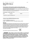
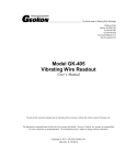
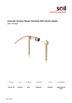
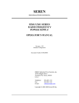
DOC1055
Rev 1.2
TMS 4500
Torque Metering System
User’s Manual
Indikon
215 Clinton Road
New Hartford, NY 13413
Voice: 315-624-7171
Fax: 315-624-7173
Indikon
1
TMS 4500 User’s Manual
System Description
The TMS 4500 is a system for monitoring torque, speed, and power on two shafts.
The system consists of two Torque Sensor/Transmitters, two Torque/Speed
Receivers, a Processing Unit, and two Monitors.
1.1
Torque Sensor/Transmitter
The Sensor/Transmitter is a disc or collar mounted on each shaft. It is powered
inductively by the Receiver, senses the torque via strain gages connected to it, and
transmits a torque signal back to the Receiver.
1.2
Torque/Speed Receiver
The Receivers are mounted below the shafts and have a ring that surrounds the
Sensor/Transmitter. It provides power to the Sensor/Transmitter, receives the
torque signal, senses rotating speed, and provides outputs to the Processor. The
electronics are enclosed in a painted steel NEMA 4 enclosure with mounting ears.
1.3
The Processor
The Processor provides power to and receives signals form the Receiver, converts
the raw signals to calibrated values, calculates power, and provides display
information to the Monitors. The Processor is housed in a fiberglass NEMA 4
enclosure. It has integrated mounting ears.
1.4
Monitors
The Monitors are powered by their own power supplies and receive display data
from the Processor. The display is a Quarter VGA color LCD touch-screen. The
display area is 4.6” wide by 3.5” high. The Monitor mounting frame is 7.7” wide by
5.7” tall. The LCD is housed in a fiberglass NEMA 4 enclosure. The enclosure is
held within a “U” shaped bracket by two large clamping knobs. The bracket can be
mounted on a horizontal or vertical surface and allows the monitor to be tilted for
optimal viewing angle. The Monitor displays torque, speed, power, and power
imbalance as values and horizontal bar graphs.
DOC1055 – Rev 1.2
Page 2
Indikon
2
TMS 4500 User’s Manual
Wiring
Cable/cord grips are provided on the Receivers, Processor, and Monitors. Standard
PVC jacketed cable is provided for all connections.
2.1
Torque/Speed Receiver Wiring
Two cables run between the Torque/Speed Receiver and the Processor; one for
12VDC power and one for analog signal wiring.
2.2
Processor Wiring
Besides the 2 cables to each Torque/Speed Receiver, there will be 3 additional
cables; one for communications with each Monitor and one for 115VAC power.
2.3
Monitor Wiring
Besides the cable from the Processor, there will be one additional cable for 115VAC
power.
3
Normal Operation
The system, as delivered, is ready for operation. After installation, apply power to
the Monitors and then the Processor. Within a few seconds the “normal display
screen” will appear with values and bar graphs. If the processor is operating
properly, all values should be white and the top line should be moving back and forth
one pixel every second.
4
User Interface
Each display has a touch screen that allows the user to access information and
change the configuration. The touch screen is relatively sensitive, so a light press is
all that is needed.
IMPORTANT NOTE
Never use sharp or pointed objects to actuate the touch screen.
Press “Indikon” to display company contact information. Then press “Exit” to return
to the normal display.
Press on the area around the speed value to display information on the color code
for the torque and speed. Then press “Exit” to return to the normal display.
Press “TMS 4500” to access the menus. The menus provide a mechanism for
modifying the setup/configuration of the system and performing calibration (primarily
intended for the factory, but also usable in the field).
The menus can be passcode protected by establishing a passcode other than zero.
It is called a “passcode” rather than a “password”, as it is numeric, not alphanumeric.
DOC1055 – Rev 1.2
Page 3
Indikon
TMS 4500 User’s Manual
To do this, press “Change Passcode” and enter a value using the numeric touch
pad. The next time someone tries to access the menus, they must first enter the
passcode.
IMPORTANT NOTE
If you forget the passcode, there is a factory passcode that can be used to
gain access and establish a new passcode. Establishing a passcode of zero
disables the passcode protection.
5
Menus
Section 9 lists the menus essentially as they appear in the display. All of the
selections not listed as “(for factory use)” may be used to reconfigure the system as
desired.
6
Zero Correction
The torque value displayed when a shaft is not turning may not be zero, due to a
slight calibration offset. If this is so, the offset can be eliminated by performing an
Auto Zero function. To do so:
Press “TMS 4500” on the LCD touchscreen.
Press “Corrections”.
Press “Auto Zero 1 (Port) for the port shaft
or
Press “Auto Zero 2 (Stbd) for the starboard shaft.
“Auto Zero Completed” will be displayed.
Press “Exit” to return to the Corrections screen.
Press “Exit” to return to the main screen.
DOC1055 – Rev 1.2
Page 4
Indikon
TMS 4500 User’s Manual
Menu List
Main Menu
Change Passcode
Corrections
Configure Display
Configure Filters
More
Exit
Enter a new value
Go to the Corrections menu
Go to the Display configuration menu
Go to the Configure Filters menu
Go to a menu with more selections
Exit to Normal Display
Corrections
Auto Zero 1 (Port)
Auto Zero 2 (Stbd)
Adjust Torque 1
Adjust Torque 2
Exit
Automatically zero the Port torque value
Automatically zero the Starboard torque value
Port torque span adjustment factor
Starboard torque span adjustment factor
Exit to Main Menu
Display Configuration
Speed Bar FS
Torque Bar FS
Power Bar FS
Imbalance Bar FS
Exit
Speed Bar Graph Full Scale value
Torque Bar Graph Full Scale value
Power Graph Full Scale value
Imbalance Graph Full Scale value
Exit to Main Menu
Filter Configuration
Speed Filter
Torque Filter
Exit
Minimum revolutions for speed value updates
Seconds of filtering for torque value updates
Exit to Main Menu
More Selections
Configure Channel 1 (Port)
Configure Channel 2 (Stbd)
Calibration
Entered Values
View Values
Exit
(for factory use)
(for factory use)
(for factory use)
(for demonstration and factory use)
(for troubleshooting use)
Exit to Main Menu
View Selections
View Inputs
View Calculations
View Comm Info
Exit
DOC1055 – Rev 1.2
(for troubleshooting use)
(for troubleshooting use)
(for troubleshooting use)
Exit to Main Menu
Page 5
Indikon
7
TMS 4500 User’s Manual
Receiver Configuration
Be sure all Torque Configuration Switches are set to OFF.
Receiver Switches and Connections
DOC1055 – Rev 1.2
Page 6
Indikon
8
TMS 4500 User’s Manual
Torque Sensor/Transmitter and Receiver
DOC1055 – Rev 1.2
Page 7
Indikon
DOC1055 – Rev 1.2
TMS 4500 User’s Manual
Page 8
Indikon
TMS 4500 User’s Manual
9 Processor
Processor Enclosure
(Mounting ears not shown)
Inside the Processor Enclosure
DOC1055 – Rev 1.2
Page 9
Indikon
TMS 4500 User’s Manual
Processor Enclosure Mounting Options
DOC1055 – Rev 1.2
Page 10
Indikon
TMS 4500 User’s Manual
10 Monitor Enclosure and Display
Monitor Packaging
Actual Monitor Appearance
DOC1055 – Rev 1.2
Page 11
Indikon
TMS 4500 User’s Manual
LCD Image
Displayed information is representative of the TMS 4500.
This image is provided to depict the resolution of the 320 by 240 pixel image.
DOC1055 – Rev 1.2
Page 12
Indikon
11
TMS 4500 User’s Manual
Specifications
Sensors
Torque Sensor
Sensing Range
Speed Sensor
Torque Accuracy
Typical Torque Accuracy
Strain gages
+/-500 microstrain
Hall-effect sensor
1% of full scale worst case
Better than 0.5%
Display
Type
Viewing Area
Resolution
TFT Color LCD Touch-Screen
4.6” wide by 3.5” high
Quarter VGA – 320 by 240 pixels
Field Wiring Connectors
Type
Operating Power
Voltage
Power Consumption Processor
Power Consumption Monitor
Fuse - Processor
Fuse - Monitor
Fuse - Receiver
Pluggable Phoenix type connectors with
captive wire clamps
85 to 265 VAC, 50/60 Hz
60 watts maximum
10 watts maximum
2 A, Slow Blow, 5x20mm
2 A, Slow Blow, 5x20mm
2 A, Slow Blow, 5x20mm
Mechanical - Torque Sensor/Transmitter and Receiver
Torque Sensor/Transmitter
Refer to separate drawing
Torque/Speed Receiver
Refer to separate drawing
Mechanical - Processor
Enclosure Type
Enclosure Dimensions
Mechanical - Monitors
Enclosure Type
Bezel Dimensions
Enclosure Dimensions
Monitor Overall Size
DOC1055 – Rev 1.2
Fiberglass
13.2” wide by 15.2” high by 7.1” deep
(excluding mounting ears)
Fiberglass
7.7” wide by 5.7” high
9.2” wide by 7.2” high by 5.1” deep
12.4” wide by 9.7” high by 6.4” deep
(including bracket, knobs, and handle)
Page 13
Indikon
Environmental
Ambient Operation Temperature
Humidity
Fiberglass Enclosure Ratings
Transportation Vibration
TMS 4500 User’s Manual
32ºF to 131ºF (0ºC to 55ºC)
0 to 100% RH, non-condensing
NEMA 4X
IAW Commercial Handling/Shipping
Warranty
Standard
DOC1055 – Rev 1.2
1 year
Page 14
Indikon
12
TMS 4500 User’s Manual
Status Indicators
There is one Main Status Indicator light located outside the Receiver at the base of
the Stationary Ring and five secondary system status indicator lights inside the unit.
Main Status - Red LED on Receiver (not on the board)
On Solid * No errors
Fast flash
a) Remote Shunt Switch is on
b) One or more system errors present
Stator - Green LED - LED1
On Solid *
Input power to system is in range
Fast flash
Input power to system is too high
Slow flash Input power to system is too low
Rotor - Green LED - LED2
On Solid *
Rotating Collar Power is in range and no data errors present
Fast flash
Rotating Collar Power is too high
Slow flash Rotating Collar Power is too low
Off
Data transmission errors
Data - Green LED - LED3
On Solid * Data received without errors
Off
Data transmission errors
(A flickering Data light indicates intermittent data transmission.)
Range - Red LED - LED4
On Solid
Sensor input to transmitter is over range
Off *
Sensor input to transmitter is within range
(The Range indicator may flash or flicker with a dynamic over-range condition.
When the Range light is on, the torque signal is in error.)
RPM - Green LED - LED5
On*
Speed sensor triggering properly
Off
Speed sensor not triggering
(Flashes 6 times per shaft revolution so will appear on solid or flashing depending on
shaft speed.)
In an error condition, the receiver output will be 24 mA.
Fast flash rate = 4 Hz; Slow flash rate = 2 Hz
* Indicates normal (error free) condition
DOC1055 – Rev 1.2
Page 15
Indikon
13
TMS 4500 User’s Manual
Troubleshooting Guide
When the Receiver is first powered up, it cycles through the startup sequence, lasting 1015 seconds. During startup mode, all of the Indicator LEDs flash in unison. If all system
checks are positive, the Main Status LED on the outside of the Receiver remains on solid,
and the system is ready for operation.
Normal Operating Mode (no errors)
Indicator
Condition
Main Status (red LED on outside)
On solid
Stator (green LED inside)
On solid
Rotor (green LED inside)
On solid
Data (green LED inside)
On solid
Range (red LED inside)
Off
If an error is present, the Main Status LED will flash and the system will display an error
code briefly (another 10-15 seconds) before the startup cycle repeats. Below are the most
common error modes and potential corrective actions.
Error Mode: Power supply voltage is incorrect
Indicator
Condition
Main Status
Fast flash (4 Hz)
Stator
Flashing (2 or 4 Hz)
DOC1055 – Rev 1.2
Suggested Corrective Action
1. Verify the approximately 12VDC powering the
Receiver.
Page 16
Indikon
TMS 4500 User’s Manual
Error Mode: Weak inductive interface
Indicator
Condition
Main Status
Fast flash (4 Hz)
Stator
On solid
Rotor
Off or slow flash (2 Hz)
Data
Off or flickering
Suggested Corrective Action
1. Verify the voltage is about 2 volts peak-peak or
0.7VAC across the Mounting Blocks on top of the
Receiver. This must be measured with an
oscilloscope or a special meter that will measure
460KHz signals.
2. Make certain the Power Ring is not shorted to the
Receiver enclosure by water or other conductive
material.
3. Remove any surrounding metal other than the shaft
within 4 inches (10 cm) of the Power Ring.
4. Clean the mating surfaces of the Power Ring and
tighten all the mounting screws.
5. Verify that the Rotating Coil voltage is about 20 volts
peak-to-peak or 7 VAC (probe the two terminal dots on
the outer surface of the Coil Boards attached to the
Rotating Collar). This must be measured with an
oscilloscope or a special meter that will measure
460KHz signals.
6. Check alignment of the Rotating Collar within the
Power Ring: their midlines should be aligned.
7. Make certain the Rotating Collar terminal strips are
soldered properly and not damaged.
Error Mode: Strain gage problem
Indicator
Condition
Main Status
Fast flash (4 Hz)
Stator
On solid
Rotor
On solid
Data
On solid
Range
On solid
DOC1055 – Rev 1.2
Suggested Corrective Action
1. Verify the excitation voltage to the gage is 4.0VDC on
older units or 2.5 VDC on newer units.
2. Check solder connections and wiring to the gage.
3. Balance the gage to reduce the offset or apply a new
gage.
Page 17
Indikon
TMS 4500 User’s Manual
14 Warranty Statement
Limited Warranty: Torque measuring equipment and accessories are warranted by the
Seller for one year to be free from defects in both materials and workmanship under normal
use and service. This warranty is in lieu of and excludes any other warranty, express or
implied, including, but not limited to, any implied warranty derived from quote or fitness of
purpose. (Manufacturer’s liability and Buyer’s limited remedies under Manufacturer’s
warranty shall be limited solely to repair, replacement, credit or refund, at the
manufacturer’s option, with respect to products supported by a Return Material
Authorization number obtained from the Manufacturer and returned to the Manufacturer.
The Manufacturer shall not be liable, under any circumstances, for consequential or
incidental damages, including, but not limited to, labor costs or loss of profits arising in
connection with the use of or inability to use products purchased from the Seller)
Product Application: The Buyer is solely responsible in determining the suitability of the
Manufacturer’s products in its application regardless of circumstances.
Manufacturer reserves the right to make future design changes to any of its products
without thereby incurring any obligations to make changes to or replacements of this
product.
Manufacturer neither makes nor authorizes any person to make on its behalf any other
guarantee or warranty concerning its products.
Service
To obtain service under this Limited Warranty call Riverhawk Customer Service
Department in New Hartford to obtain an RMA (Return Material Authorization) number.
Pack the item(s) in its original shipping container (or equivalent)
Put the RMA number on the address label
Put the RMA number on the shipping carton
Insure it (or assume the risk of loss / damage during shipment)
Ship the product freight pre-paid to New Hartford
Manufacturer is not responsible for damage to inbound product.
Riverhawk (Headquarters)
215 Clinton Road
New Hartford, NY 13413
Voice: 315-624-7171
Fax: 315-624-7173
DOC1055 – Rev 1.2
Page 18